

Page 1
SPLIT-TYPE AIR CONDITIONERS
OUTDOOR UNIT
Revision H:
• Indoor units combinations for 42 class
have been added.
•
MXZ-3A54VA- E7 and MXZ-4A71VA- E7
have been added.
Please void OB377 REVISED EDITION-G.
SERVICE MANUAL
Models
E1
MXZ-2A30VA MXZ-2A30VA MXZ-2A40VA MXZ-2A40VA MXZ-2A52VA MXZ-2A52VA MXZ-3A54VA MXZ-3A54VA MXZ-3A54VA MXZ-3A54VA MXZ-3A54VA MXZ-3A54VA MXZ-3A54VA MXZ-4A71VA -
E2
E1
E2
E1
E2
E1
E2
E3
E4
E5
E6
E7
E1
MXZ-4A71VA MXZ-4A71VA MXZ-4A71VA MXZ-4A71VA MXZ-4A71VA MXZ-4A71VA MXZ-4A80VA MXZ-4A80VA MXZ-5A100VA -
Indoor unit service manual
MSZ-FA•VA Series (OB371)
MSZ-GA•VA Series (OB378, OB388)
MSZ-CB•VA Series (OB441)
MSZ-GC•VA Series (OBH468)
MSZ-GE•VA Series (OBH515)
MSZ-FD•VA Series (OBH488)
HFC
utilized
R410A
No. OB377
REVISED EDITION-H
E2
E3
E4
E5
E6
E7
E1
E2
E1
MXZ-4A80VA-
NOTE:
• RoHS compliant products have <G> mark on the spec
name plate.
For servicing of RoHS compliant products, refer to the
RoHS Parts List.
E1
CONTENTS
1. TECHNICAL CHANGES ··································· 2
2. PART NAMES AND FUNCTIONS ····················· 8
3. INDOOR/OUTDOOR
CORRESPONDENCE TABLE ························ 10
4. INDOOR UNITS COMBINATION ···················· 14
5. SPECIFICATION ·············································· 61
6. NOISE CRITERIA CURVES ···························· 66
7. OUTLINES AND DIMENSIONS ······················ 68
8. WIRING DIAGRAM ·········································· 75
9. REFRIGERANT SYSTEM DIAGRAM ············· 87
10. PERFORMANCE CURVES ····························· 97
11. ACTUATOR CONTROL ··································115
12. SERVICE FUNCTIONS ···································116
13. TROUBLESHOOTING ··································· 120
14. DISASSEMBLY INSTRUCTIONS ·················· 145
15. PARTS LIST ··················································· 160
16. RoHS PARTS LIST ········································ 172
17. OPTIONAL PARTS ······················BACK COVER
Page 2

Revision A :
• MXZ-3A54VA-E1 and MXZ-4A71VA-E2 have been added.
Quick clean kit has been removed. (Refer to 2.)
• MXZ-2A40VA-
E1
and MXZ-2A52VA-E2 have been added.
Revision B :
• MXZ-2A30VA-E1 and MXZ-2A40VA-E2 have been added.
• “Check of HPS” has been corrected.
• RoHS PARTS LIST has been added.
Revision C :
• MXZ-2A52VA-
E2
, MXZ-3A54VA-E3, MXZ-4A71VA-E3, MXZ-4A80VA-E2 and MXZ-5A100VA-E1 have been added.
Revision D:
• MXZ-3A54VA-E4, and MXZ-4A71VA-E4 have been added.
• The content of pre-heat control (12-3) has been corrected.
• 5. SPECIFICATION has been corrected.
Revision E:
• MXZ-2A30VA-E1 has been added.
• 4. INDOOR UNITS COMBINATION of MXZ-5A100VA-
E2
has been changed.
Revision F:
• MXZ-3A54VA-
E5
and MXZ-4A71VA-
E5
have been added.
Revision G:
• MXZ-3A54VA-
E6
and MXZ-4A71VA-
E6
have been added.
Revision H:
• Indoor units combinations for 42 class have been added.
•
MXZ-3A54VA- E7 and MXZ-4A71VA- E7
1
MXZ-A26WV -
1. Indication of capacity has been changed. (BTU kW)
2. Capacity specification has been changed. (Cooling capacity 7.1kW
3. Dimensions of unit have been changed. (W900 H900 D320 W840
4. Combinations of connectable indoor units have been changed.
5. Capacity class of connectable indoor units has been changed.
6. Communication system has been changed.
7. Power supply way has been changed (change to supply to outdoor unit).
8. Compressor has been changed. (TNB220FMCH
9. High-pressure switch has been removed.
10.Outdoor fan motor has been changed. (PM8H60-UA RC0J60-AA)
11.Evaporation temperature thermistor has been removed.
12.Ambient temperature thermistor has been added.
13.New dip switch has been added to the controller board for "Locking the operation "mode
and "Lowering the operating noise "mode.
14.A Quick Clean Kit has been added.
MXZ-A32WV -
1. Indication of capacity has been changed. (BTU kW)
2. Capacity specification has been changed. (Cooling capacity 8.0kW
3. Dimensions of unit have been changed. (W900 H900 D320
4. Combinations of connectable indoor units have been changed.
5. Capacity class of connectable indoor units has been changed.
6. Communication system has been changed.
7. Power supply way has been changed (change to supply to outdoor unit).
8. Compressor has been changed. (TNB220FMCH SNB130FLDH1)
9. High-pressure switch has been removed.
10. Outdoor fan motor has been changed. (PM8H60-UA RC0J60-AA)
11. Evaporation temperature thermistor has been removed.
12. Ambient temperature thermistor has been added.
13. New dip switch has been added to the controller board for "Locking the operation "mode
and "Lowering the operating noise "mode.
14. A Quick Clean Kit has been added.
TECHNICAL CHANGES
E1
MXZ-3A54VA -
E1
MXZ-4A71VA -
have been added.
E1
SNB130FLDH1)
E1
5.4kW)
H710 D330)
7.1kW)
W840 H710 D330)
2
Page 3
MXZ-A32WV -
E1
MXZ-4A80VA -
E1
1. Indication of capacity has been changed. (BTU kW)
2. Communication system has been changed.
3. Power supply way has been changed (change to supply to outdoor unit).
4. Evaporation temperature thermistor has been removed.
5. Ambient temperature thermistor has been added.
6. New dip switch has been added to the controller board for "Locking the operation "mode
and "Lowering the operating noise "mode.
7. A Quick Clean Kit has been added.
MXZ-A14WV -
E2
MXZ-2A40VA -
E1
1. Indication of capacity has been changed. (BTU kW)
2. Dimensions of unit have been changed. (W840
H640 D330 W800 H550 D285)
3. Communication system has been changed.
4. Power supply way has been changed (change to supply to outdoor unit).
5. Compressor has been changed. (SNV092FJYH SNB130FKCH)
6. Outdoor fan motor has been changed. (RA6V49 RC0J50-CF)
7. Evaporation temperature thermistor has been removed.
8. Gas pipe temperature thermistor has been removed.
9. Ambient temperature thermistor has been added.
MXZ-A18WV -
E2
MXZ-2A52VA -
E1
1. Indication of capacity has been changed. (BTU kW)
2. Cooling capacity specification has been changed. (5.4 kW
5.2 kW)
3. Heating capacity specification has been changed. (6.6 kW 6.4 kW)
4. Dimensions of unit have been changed. (W840 H640
D330 W800 H550 D285)
5. Communication system has been changed.
6. Power supply way has been changed (change to supply to outdoor unit).
7. Compressor has been changed. (SNV092FJYH
SNB130FKCH)
8. Outdoor fan motor has been changed. (RA6V49 RC0J50-CF)
9. Evaporation temperature thermistor has been removed.
10. Gas pipe temperature thermistor has been removed.
11. Ambient temperature thermistor has been added.
MXZ-3A54VA MXZ-4A71VA -
E1
MXZ-3A54VA -
E1
MXZ-4A71VA -
E2
E2
1. Quick clean kit has been removed.
MXZ-2A30VA -
E1
1. New model
MXZ-2A40VA -
E1
MXZ-2A40VA -
E2
1. Compressor has been changed. (SNB130FKCH KNB092FEDH)
2. Outdoor heat exchanger has been changed.
MXZ-2A52VA -
E1
MXZ-2A52VA -
E2
1. Compressor has been changed. (SNB130FKCH SNB130FKMH)
2. Inverter P.C. board has been changed.
3
Page 4
MXZ-3A54VA -
E2
MXZ-3A54VA -
E3
1. Compressor has been changed. (SNB130FLDH1 SNB130FLEH1)
2. Electronic control P.C. board has been changed.
MXZ-4A71VA -
E2
MXZ-4A71VA -
E3
1. Compressor has been changed. (SNB130FLDH1 SNB130FLEH1)
2. Electronic control P.C. board has been changed.
MXZ-4A80VA -
E1
MXZ-4A80VA -
E2
1. Ball valve has been changed to stop valve.
2. Gas pipe temperature thermistor has been removed.
3. Pre-heat control has been added.
4. Auto line correcting function has been added.
5. Noise filter P.C. board has been changed.
6. Electronic control P.C. board has been changed.
7. Weight has been changed. (70kg 67kg)
MXZ-5A100VA -
E1
1. New model
MXZ-3A54VA -
E3
MXZ-3A54VA -
E4
1. Compressor has been changed. (SNB130FLEH1 SNB130FGBH1)
2. Electronic control P.C. board has been changed.
3. Gas pipe temperature thermistor has been removed.
4. Pre-heat control has been added.
5. Power board has been changed.
MXZ-4A71VA -
E3
MXZ-4A71VA -
E4
1. Compressor has been changed. (SNB130FLEH1 SNB130FGBH1)
2. Electronic control P.C. board has been changed.
3. Gas pipe temperature thermistor has been removed.
4. Pre-heat control has been added.
5. Power board has been changed.
MXZ-2A30VA -
E1
MXZ-2A30VA -
E2
1. Compressor has been changed. (KNB092FEDH KNB073FGDH)
2. Inverter P.C. board has been changed.
MXZ-3A54VA -
E4
MXZ-3A54VA -
E5
1. Electronic control P.C. board has been changed.
2. Noise filter P.C. board has been changed.
3. Ball valve has been changed to stop valve.
4. Sub panel has been added.
MXZ-4A71VA -
E4
MXZ-4A71VA -
E5
1. Electronic control P.C. board has been changed.
2. Noise filter P.C. board has been changed.
3. Ball valve has been changed to stop valve.
4. Sub panel has been added.
MXZ-3A54VA MXZ-4A71VA -
E5
MXZ-3A54VA -
E5
MXZ-4A71VA -
E6
E6
1. Electronic control P.C. board has been changed.
MXZ-3A54VA MXZ-4A71VA -
E6
MXZ-3A54VA -
E6
MXZ-4A71VA -
E7
E7
1. Electronic control P.C. board has been changed.
2. Compressor has been changed. (SNB130FGBH1 SNB130FGBH1T)
4
Page 5
INFORMATION FOR THE AIR CONDITIONER WITH R410A REFRIGERANT
• This room air conditioner adopts HFC refrigerant (R410A) which never destroys the ozone layer.
• Pay particular attention to the following points, though the basic installation procedure is same as that for R22 air conditioners.
As R410A has working pressure approximately 1.6 times as high as that of R22, some special tools and piping parts/
materials are required. Refer to the table below.
Take sufficient care not to allow water and other contaminations to enter the R410A refrigerant during storage and
installation, since it is more susceptible to contaminations than R22.
For refrigerant piping, use clean, pressure-proof parts/materials specifically designed for R410A. (Refer to 2. Refrigerant
piping.)
Composition change may occur in R410A since it is a mixed refrigerant. When charging, charge liquid refrigerant to prevent
composition change.
Refrigerant
Composition (Ratio)
Refrigerant handling
Chlorine
Safety group (ASHRAE)
Molecular weight
Boiling point (°C)
Steam pressure [25°C](Mpa)
Refrigerant
Saturated steam density [25°C](Kg/m
3
)
Combustibility
ODP 1
GWP 2
Refrigerant charge method
Additional charge on leakage
Kind
Color
oil
Smell
Refrigeration
1 :Ozone Depletion Potential : based on CFC-11
2 :Global Warming Potential : based on CO
2
New refrigerant
R410A
HFC-32: HFC-125 (50%:50%)
Pseudo-azeotropic refrigerant
Not included
A1/A1
72.6
-51.4
1.557
64
Non combustible
0
1730
From liquid phase in cylinder
Possible
Incompatible oil
Non
Non
Previous refrigerant
R22
R22 (100%)
Single refrigerant
Included
A1
86.5
-40.8
0.94
44.4
Non combustible
0.055
1700
Gas phase
Possible
Compatible oil
Light yellow
Non
5
Page 6
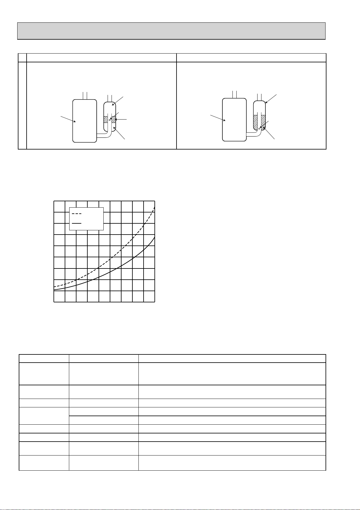
New Specification Current Specification
The incompatible refrigeration oil easily separates from
refrigerant and is in the upper layer inside the suction muffler.
Raising position of the oil back hole enables to back the
refrigeration oil of the upper layer to flow back to the
compressor.
Suction muffler
Since refrigerant and refrigeration oil are compatible,
refrigeration oil goes back to the compressor through the
lower position oil back hole.
Suction muffler
Compressor
Compressor
Oil back hole
Refrigeration oil
Refrigerant
Compressor
Oil back hole
Refrigeration oil /Refrigerant
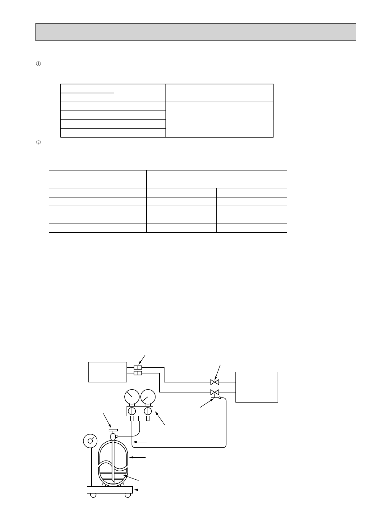
NOTE : The unit of pressure has been changed to MPa on the international system of units (SI unit system).
The conversion factor is: 1(MPa [Gauge]) =10.2(kgf/cm
2
[Gauge])
Conversion chart of refrigerant temperature and pressure
(MPa [Gauge])
4.0
3.5
3.0
2.5
2.0
1.5
1.0
0.5
Saturated liquid pressure
0.0
R410A
R22
NOTE : The unit of pressure has been changed to MPa on the
international system of units (SI unit system).
The conversion factor is: 1(MPa [Gauge]) =10.2(kgf/cm2 [Gauge])
-0.5
-30 -20 -10 0 10 20
30
40 50 60
(°C)
1. Tools dedicated for the air conditioner with R410A refrigerant
The following tools are required for R410A refrigerant. Some R22 tools can be substituted for R410A tools.
The diameter of the service port on the stop valve in outdoor unit has been changed to prevent any other refrigerant from
being charged into the unit. Cap size has been changed from 7/16 UNF with 20 threads to 1/2 UNF with 20 threads.
R410A tools
Can R22 tools be used?
R410A has high pressures beyond the measurement range of existing
Gauge manifold
No
gauges. Port diameters have been changed to prevent any other refrigerant
from being charged into the unit.
Charge hose
Gas leak detector
Torque wrench
No
No
Yes
Hose material and cap size have been changed to improve the pressure
resistance.
Dedicated for HFC refrigerant.
6.35 mm and 9.52 mm
No 12.7 mm and 15.88 mm
Flare tool
Flare gauge
Vacuum pump
adapter
Electronic scale for
refrigerant charging
Yes
New
New
New
Clamp bar hole has been enlarged to reinforce the spring strength in the tool.
Provided for flaring work (to be used with R22 flare tool).
Provided to prevent the back flow of oil. This adapter enables you to use
vacuum pumps.
It is difficult to measure R410A with a charging cylinder because the
refrigerant bubbles due to high pressure and high-speed vaporization
No: Not Substitutable for R410A Yes: Substitutable for R410A
Description
6
Page 7
2. Refrigerant piping
Specifications
Use the copper or copper-alloy seamless pipe for refrigerant that meet the following specifications.
Outside diameter
mm
6.35
9.52
12.7
15.88
Flaring work and flare nut
Flaring work for R410A pipe differs from that for R22 pipe.
For details of flaring work, refer to Installation manual “FLARING WORK”.
Pipe diameter
mm
6.35
9.52
12.7
15.88
Wall thickness
0.8 mm
0.8 mm
0.8 mm
1.0 mm
Heat resisting foam plastic
Specific gravity 0.045 Thickness 8 mm
R410A
Insulation material
Dimension of flare nut
17
22
26
29
R22
17
22
24
27
3. Refrigeration oil
Apply the special refrigeration oil (accessories: packed with indoor unit) to the flare and the union seat surfaces.
4. Air purge
• Do not discharge the refrigerant into the atmosphere.
Take care not to discharge refrigerant into the atmosphere during installation, reinstallation, or repairs to the refrigerant
circuit.
• Use the vacuum pump for air purging for the purpose of environmental protection.
5. Additional charge
For additional charging, charge the refrigerant from liquid phase of the gas cylinder.
If the refrigerant is charged from the gas phase, composition change may occur in the refrigerant inside the cylinder and the
outdoor unit. In this case, ability of the refrigeration cycle decreases or normal operation can be impossible. However,
charging the liquid refrigerant all at once may cause the compressor to be locked. Thus, charge the refrigerant slowly.
Union
Stop valve
Indoor unit
Refrigerant gas
cylinder
operating valve
Charge hose (for R410A)
Refrigerant gas cylinder
for R410A with siphon
Refrigerant (liquid)
Electronic scale for refrigerant charging
Liquid pipe
Gas pipe
Service port
Gauge manifold
valve (for R410A)
Outdoor unit
7
Page 8

2
PART NAMES AND FUNCTIONS
MXZ-2A30VA
MXZ-2A40VA
MXZ-2A52VA
MXZ-3A54VAMXZ-4A71VA-
E5, E6, E7
E5, E6, E7
Air inlet
(Back and side)
Piping
Drain hose
Air outlet
Drain outlet
MXZ-3A54VA-E1, E2, E3,
MXZ-4A71VA-E1, E2, E3,
E4
E4
Air inlet
(Back and side)
Air outlet
Drain outlet
Air inlet
(Back and side)
Air outlet
Drain outlet
8
Page 9
MXZ-4A80VA-
E1
MXZ-4A80VA-
E2
MXZ-5A100VA
ACCESSORIES
Drain socket
Drain cap
Quick Clean kit
Air inlet
(Back and side)
Air outlet
Drain outlet
MXZ-2A30VA
MXZ-2A40VA
MXZ-2A52VA
1
-
-
MXZ-3A54VA MXZ-4A71VA -
1
2
1
MXZ-3A54VA -
E1
MXZ-4A71VA -
E1
MXZ-4A80VA
MXZ-5A100VA
Air inlet
(Back and side)
Air outlet
Drain outlet
E2 , E3 , E4 , E5 , E6 , E7
E2 , E3 , E4 , E5 , E6 , E7
1
2
-
9
Page 10

3
INDOOR/OUTDOOR CORRESPONDENCE TABLE
There is no combination other than this table.
MXZ-2A30VA
22+22
22+25
combination
Indoor units
combination
Indoor units
combination
Indoor units
Indoor units combination
25+25
MXZ-2A40VA
22+22
22+25
22+35
25+25
25+35
MXZ-2A52VA
22+22
22+25
22+35
25+25
25+35
35+35
MXZ-3A54VA
22+22
22+25
22+35
22+42
22+50
25+25
25+35
25+42
25+50
35+35
35+42
35+50
42+42
42+50
50+50
22+22+22
22+22+25
22+22+35
22+22+42
22+22+50
22+25+25
22+25+35
22+25+42
22+25+50
22+35+35
22+35+42
25+25+25
25+25+35
25+25+42
25+25+50
25+35+35
MXZ-4A71VA
22+22
22+25
22+35
22+42
22+50
22+60
25+25
25+35
25+42
25+50
25+60
35+35
35+42
35+50
35+60
42+42
42+50
42+60
50+50
50+60
60+60
22+22+22
22+22+25
22+22+35
22+22+42
22+22+50
22+22+60
Indoor units combination
22+25+25
22+25+35
22+25+42
22+25+50
22+25+60
22+35+35
22+35+42
22+35+50
22+35+60
22+42+42
22+42+50
22+42+60
22+50+50
25+25+25
25+25+35
25+25+42
25+25+50
25+25+60
25+35+35
25+35+42
25+35+50
25+35+60
25+42+42
25+42+50
25+50+50
35+35+35
35+35+42
MXZ-4A71VA
35+35+50
35+42+42
22+22+22+22
22+22+22+25
22+22+22+35
22+22+22+42
22+22+22+50
22+22+25+25
22+22+25+35
22+22+25+42
22+22+25+50
22+22+35+35
22+22+35+42
22+25+25+25
22+25+25+35
22+25+25+42
Indoor units combination
22+25+25+50
22+25+35+35
22+25+35+42
25+25+25+25
25+25+25+35
25+25+25+42
25+25+25+50
25+25+35+35
10
Page 11
There is no combination other than this table.
MXZ-4A80VA MXZ-4A80VA MXZ-4A80VA
22+22
22+25
22+35
22+42
22+50
22+60
22+71
25+25
25+35
25+42
25+50
25+60
25+71
35+35
35+42
35+50
35+60
35+71
42+42
42+50
42+60
42+71
50+50
50+60
50+71
60+60
60+71
Indoor units combination
22+22+22
22+22+25
22+22+35
22+22+42
22+22+50
22+22+60
22+22+71
22+25+25
22+25+35
22+25+42
22+25+50
22+25+60
22+25+71
22+35+35
22+35+42
22+35+50
22+35+60
22+35+71
22+42+42
22+42+50
22+42+60
22+42+71
22+50+50
22+50+60
22+50+71
25+25+25
25+25+35
Indoor units combination
25+25+42
25+25+50
25+25+60
25+25+71
25+35+35
25+35+42
25+35+50
25+35+60
25+35+71
25+42+42
25+42+50
25+42+60
25+42+71
25+50+50
25+50+60
35+35+35
35+35+42
35+35+50
35+35+60
35+35+71
35+42+42
35+42+50
35+42+60
35+50+50
35+50+60
22+22+22+22
22+22+22+25
22+22+22+35
22+22+22+42
22+22+22+50
22+22+22+60
22+22+22+71
22+22+25+25
22+22+25+35
22+22+25+42
22+22+25+50
22+22+25+60
22+22+25+71
22+22+35+35
22+22+35+42
22+22+35+50
22+22+35+60
22+22+42+42
22+22+42+50
22+22+50+50
22+25+25+25
22+25+25+35
22+25+25+42
22+25+25+50
22+25+25+60
22+25+35+35
22+25+35+42
22+25+35+50
22+25+35+60
22+35+35+35
22+35+35+42
22+35+35+50
22+35+42+42
25+25+25+25
25+25+25+35
25+25+25+42
25+25+25+50
25+25+25+60
25+25+35+35
25+25+35+42
25+25+35+50
Indoor units combination
25+35+35+35
25+35+35+42
35+35+35+35
11
Page 12
There is no combination other than this table.
MXZ-5A100VA
22+22
22+25
22+35
22+42
22+50
22+60
22+71
25+25
25+35
25+42
25+50
25+60
25+71
35+35
35+42
35+50
35+60
35+71
42+42
42+50
42+60
42+71
50+50
50+60
50+71
60+60
60+71
Indoor units combination
71+71
22+22+22
22+22+25
22+22+35
22+22+42
22+22+50
22+22+60
22+22+71
22+25+25
22+25+35
22+25+42
22+25+50
22+25+60
22+25+71
22+35+35
22+35+42
22+35+50
22+35+60
22+35+71
22+42+42
22+42+50
22+42+60
22+42+71
22+50+50
22+50+60
22+50+71
MXZ-5A100VA
22+60+60
22+60+71
25+25+25
25+25+35
25+25+42
25+25+50
25+25+60
25+25+71
25+35+35
25+35+42
25+35+50
25+35+60
25+35+71
25+42+42
25+42+50
25+42+60
25+42+71
25+50+50
25+50+60
25+50+71
25+60+60
25+60+71
35+35+35
35+35+42
35+35+50
35+35+60
35+35+71
Indoor units combination
35+42+42
35+42+50
35+42+60
35+42+71
35+50+50
35+50+60
35+50+71
35+60+60
35+60+71
42+42+42
42+42+50
42+42+60
42+42+71
42+50+50
42+50+60
42+50+71
42+60+60
50+50+50
50+50+60
50+50+71
22+22+22+22
22+22+22+25
22+22+22+35
22+22+22+42
22+22+22+50
22+22+22+60
MXZ-5A100VA
22+22+22+71
22+22+25+25
22+22+25+35
22+22+25+42
22+22+25+50
22+22+25+60
22+22+25+71
22+22+35+35
22+22+35+42
22+22+35+50
22+22+35+60
22+22+35+71
22+22+42+42
22+22+42+50
22+22+42+60
22+22+42+71
22+22+50+50
22+22+50+60
22+22+50+71
22+25+25+25
22+25+25+35
22+25+25+42
22+25+25+50
22+25+25+60
22+25+25+71
22+25+35+35
22+25+35+42
22+25+35+50
Indoor units combination
22+25+35+60
22+25+35+71
22+25+42+42
22+25+42+50
22+25+42+60
22+25+42+71
22+25+50+50
22+25+50+60
22+25+50+71
22+35+35+35
22+35+35+42
22+35+35+50
22+35+35+60
22+35+35+71
22+35+42+42
22+35+42+50
22+35+42+60
22+35+42+71
22+35+50+50
22+35+50+60
22+42+42+42
22+42+42+50
22+42+42+60
22+42+50+50
25+25+25+25
MXZ-5A100VA
25+25+25+35
25+25+25+42
25+25+25+50
25+25+25+60
25+25+25+71
25+25+35+35
25+25+35+42
25+25+35+50
25+25+35+60
25+25+35+71
25+25+42+42
25+25+42+50
25+25+42+60
25+25+42+71
25+25+50+50
25+25+50+60
25+25+50+71
25+35+35+35
25+35+35+42
25+35+35+50
25+35+35+60
25+35+35+71
25+35+42+42
25+35+42+50
25+35+42+60
25+42+42+42
25+42+42+50
25+42+42+60
Indoor units combination
25+42+50+50
35+35+35+35
35+35+35+42
35+35+35+50
35+35+35+60
35+35+42+42
35+35+42+50
35+42+42+42
35+42+42+50
42+42+42+42
22+22+22+22+22
22+22+22+22+25
22+22+22+22+35
22+22+22+22+42
22+22+22+22+50
22+22+22+22+60
22+22+22+22+71
22+22+22+25+25
22+22+22+25+35
22+22+22+25+42
22+22+22+25+50
22+22+22+25+60
22+22+22+25+71
22+22+22+35+35
22+22+22+35+42
12
Page 13
There is no combination other than this table.
MXZ-5A100VA
22+22+22+35+50
22+22+22+35+60
22+22+22+35+71
22+22+22+42+42
22+22+22+42+50
22+22+22+42+60
22+22+25+25+25
22+22+25+25+35
22+22+25+25+42
22+22+25+25+50
22+22+25+25+60
22+22+25+25+71
22+22+25+35+35
22+22+25+35+42
22+22+25+35+50
22+22+25+35+60
22+22+25+42+42
22+22+25+42+50
22+22+25+42+60
22+22+35+35+35
22+22+35+35+42
22+22+35+35+50
22+22+35+42+42
22+22+35+42+50
22+22+42+42+42
22+25+25+25+25
22+25+25+25+35
22+25+25+25+42
Indoor units combination
22+25+25+25+50
22+25+25+25+60
22+25+25+25+71
22+25+25+35+35
22+25+25+35+42
22+25+25+35+50
22+25+25+35+60
22+25+25+42+42
22+25+25+42+50
22+25+35+35+35
22+25+35+35+42
22+25+35+35+50
22+25+35+42+42
22+35+35+35+35
22+35+35+35+42
25+25+25+25+25
25+25+25+25+35
25+25+25+25+42
25+25+25+25+50
25+25+25+25+60
25+25+25+25+71
25+25+25+35+35
25+25+25+35+42
25+25+25+35+50
25+25+25+35+60
MXZ-5A100VA
25+25+25+42+42
25+25+25+42+50
25+25+35+35+35
25+25+35+35+42
25+25+35+35+50
Indoor units
combination
25+25+35+42+42
13
Page 14
INDOOR UNITS COMBINATION4
MXZ-2A30VA
Indoor units
combination
22
25
22+22
22+25
25+25
Indoor units
combination
22
25
22+22
22+25
25+25
Unit A
2.20
2.50
1.40
1.40
1.50
Unit A
3.30
3.60
1.90
1.90
2.00
Cooling capacity (kW)
Unit B
–
–
1.40
1.50
1.50
Heating capacity (kW)
Unit B
–
–
1.90
2.00
2.00
Total
2.2
(0.9 - 3.0)
2.5
(0.9 - 3.3)
2.8
( 1.1 - 3.8)
2.9
(1.1 - 3.9)
3.0
(1.1 - 4.0)
Total
3.3
(0.9 - 4.0)
3.6
(0.9 - 4.5)
3.8
(1.0 - 4.3)
3.9
(1.0 - 4.4)
4.0
(1.0 - 4.5)
NOTE: Electrical data is for outdoor unit only.
Outdoor unit
power consumption
(kW)
0.430
(0.120 - 0.620)
0.490
(0.120 - 0.690)
0.540
(0.250 - 0.970)
0.565
(0.250 - 1.020)
0.595
(0.250 - 1.070)
NOTE: Electrical data is for outdoor unit only.
Outdoor unit
power consumption
(kW)
0.670
(0.110 - 0.910)
0.730
(0.110 - 1.050)
0.705
(0.200 - 0.770)
0.725
( 0.200 - 0.795)
0.745
(0.200 - 0.810)
Current
(A)
2.08
2.37
2.61
2.73
2.87
Current
(A)
3.24
3.53
3.41
3.50
3.60
Power
factor
(%)
90
90
90
90
90
Power
factor
(%)
90
90
90
90
90
14
Page 15
MXZ-2A40VA
Indoor units
combination
22
25
35
22+22
22+25
22+35
25+25
25+35
Indoor units
combination
22
25
35
22+22
22+25
22+35
25+25
25+35
Unit A
2.20
2.50
3.50
1.90
1.83
1.51
1.95
1.67
Unit A
3.30
3.60
4.00
2.20
2.06
1.70
2.20
1.85
Cooling capacity (kW)
Unit B
–
–
–
1.90
2.07
2.39
1.95
2.33
Heating capacity (kW)
Unit B
–
–
–
2.20
2.34
2.70
2.20
2.65
Total
2.2
(0.9 - 3.0)
2.5
(0.9 - 3.3)
3.5
(0.9 - 4.0)
3.8
( 1.1 - 4.3)
3.9
(1.1 - 4.3)
3.9
(1.1 - 4.4)
3.9
(1.1 - 4.4)
4.0
(1.1 - 4.5)
Total
3.3
(0.9 - 4.0)
3.6
(0.9 - 4.5)
4.0
(0.9 - 4.8)
4.4
(1.0 - 4.8)
4.4
(1.0 - 4.8)
4.4
(1.0 - 4.9)
4.4
(1.0 - 4.9)
4.5
(1.0 - 5.0)
NOTE: Electrical data is for outdoor unit only.
Outdoor unit
power consumption
(kW)
0.430
(0.120 - 0.620)
0.490
(0.120 - 0.690)
0.730
(0.120 - 0.900)
0.830
(0.250 - 1.110)
0.970
(0.250 - 1.110)
0.970
(0.250 - 1.130)
0.970
(0.250 - 1.130)
1.045
(0.250 - 1.170)
NOTE: Electrical data is for outdoor unit only.
Outdoor unit
power consumption
(kW)
0.670
(0.110 - 0.910)
0.730
(0.110 - 1.050)
0.870
(0.110 - 1.150)
0.910
(0.200 - 1.010)
0.910
( 0.200 - 1.010)
0.910
(0.200 - 1.030)
0.910
(0.200 - 1.030)
0.945
(0.200 - 1.050)
Current
(A)
2.08
2.37
3.53
3.80
4.44
4.44
4.44
4.78
Current
(A)
3.24
3.53
4.20
4.16
4.16
4.16
4.16
4.32
Power
factor
(%)
90
90
90
95
95
95
95
95
Power
factor
(%)
90
90
90
95
95
95
95
95
15
Page 16
MXZ-2A52VA
Indoor units
combination
22
25
35
22+22
22+25
22+35
25+25
25+35
35+35
Indoor units
combination
22
25
35
22+22
22+25
22+35
25+25
25+35
35+35
Unit A
2.20
2.50
3.50
2.20
2.20
1.93
2.50
2.13
2.60
Unit A
3.30
3.60
4.00
3.05
2.90
2.43
3.15
2.63
3.20
Cooling capacity (kW)
Unit B
–
–
–
2.20
2.50
3.07
2.50
2.97
2.60
Heating capacity (kW)
Unit B
–
–
–
3.05
3.30
3.87
3.15
3.67
3.20
Total
2.2
(0.9 - 3.0)
2.5
(0.9 - 3.3)
3.5
(0.9 - 4.0)
4.4
(1.1 - 5.3)
4.7
(1.1 - 5.4)
5.0
(1.1 - 5.6)
5.0
(1.1 - 5.6)
5.1
(1.1 - 5.8)
5.2
(1.1 - 6.0)
Total
3.3
( 0.9 - 4.0)
3.6
(0.9 - 4.5)
4.0
(0.9 - 4.8)
6.1
(1.0 - 6.7)
6.2
(1.0 - 6.8)
6.3
(1.0 - 7.0)
6.3
(1.0 - 7.0)
6.3
(1.0 - 7.1)
6.4
(1.0 - 7.2)
NOTE: Electrical data is for outdoor unit only.
Outdoor unit
power consumption
(kW)
0.430
(0.120 - 0.620)
0.490
(0.120 - 0.690)
0.730
(0.120 - 0.900)
1.130
(0.250-1.510)
1.250
(0.250 - 1.560)
1.400
(0.250 - 1.650)
1.400
(0.250 - 1.650)
1.450
(0.250 - 1.740)
1.505
(0.250 - 1.830)
NOTE: Electrical data is for outdoor unit only.
Outdoor unit
power consumption
(kW)
0.670
(0.110 - 0.910)
0.730
(0.110 - 1.050)
0.870
(0.110 - 1.150)
1.550
(0.200 - 1.730)
1.600
(0.200 - 1.750)
1.650
(0.200 - 1.790)
1.650
(0.200 - 1.790)
1.650
(0.200 - 1.820)
1.705
(0.200 - 1.840)
Current
(A)
2.08
2.37
3.53
5.12
5.66
6.28
6.28
6.50
6.75
Current
(A)
3.24
3.53
4.20
6.95
7.17
7.40
7.40
7.40
7.64
Power
factor
(%)
90
90
90
96
96
97
97
97
97
Power
factor
(%)
90
90
90
97
97
97
97
97
97
16
Page 17

MXZ-3A54VA
Indoor units
combination
22
25
35
42
50
22+22
22+25
22+35
22+42
22+50
25+25
25+35
25+42
25+50
35+35
35+42
35+50
42+42
42+50
50+50
22+22+22
22+22+25
22+22+35
22+22+42
22+22+50
22+25+25
NOTE: Electrical data is for outdoor unit only.
Cooling capacity (kW)
Unit A Unit B Unit C Total
2.2 - - 2.2 0.590 2.59 99
( 1.4 - 3.0 ) ( 0.420 - 0.740 )
2.5 - - 2.5 0.660 2.90 99
( 1.4 - 3.3 ) ( 0.420 - 0.830 )
3.5 - - 3.5 0.950 4.17 99
( 1.5 - 4.3 ) ( 0.430 - 1.180 )
4.2 - - 4.2 1.220 5.36 99
( 1.6 - 5.0 ) ( 0.450 - 1.420 )
5.0 - - 5.0 1.500 6.59 99
( 1.6 - 5.6 ) ( 0.480 - 1.660 )
2.2 2.2 - 4.4 1.180 5.18 99
( 2.0 - 5.4 ) ( 0.540 - 1.450 )
2.2 2.5 - 4.7 1.300 5.71 99
( 2.0 - 5.8 ) ( 0.540 - 1.630 )
2.08 3.32 - 5.4 1.600 7.03 99
( 2.0 - 6.8 ) ( 0.540 - 2.550 )
1.86 3.54 - 5.4 1.590 6.98 99
( 2.0 - 6.8 ) ( 0.540 - 2.490 )
1.65 3.75 - 5.4 1.580 6.94 99
( 2.0 - 6.8 ) ( 0.550 - 2.440 )
2.5 2.5 - 5.0 1.420 6.24 99
( 2.0 - 6.0 ) ( 0.540 - 1.750 )
2.25 3.15 - 5.4 1.600 7.03 99
( 2.0 - 6.8 ) ( 0.540 - 2.550 )
2.01 3.39 - 5.4 1.590 6.98 99
( 2.0 - 6.8 ) ( 0.540 - 2.490 )
1.8 3.6 - 5.4 1.580 6.94 99
( 2.0 - 6.8 ) ( 0.550 - 2.440 )
2.7 2.7 - 5.4 1.600 7.03 99
( 2.0 - 6.8 ) ( 0.540 - 2.550 )
2.4 3.0 - 5.4 1.560 6.85 99
( 2.0 - 6.8 ) ( 0.540 - 2.490 )
2.22 3.18 - 5.4 1.530 6.72 99
( 2.0 - 6.8 ) ( 0.550 - 2.440 )
2.7 2.7 - 5.4 1.530 6.72 99
( 2.0 - 6.8 ) ( 0.550 - 2.440 )
2.47 2.93 - 5.4 1.540 6.76 99
( 2.1 - 6.8 ) ( 0.550 - 2.390 )
2.7 2.7 - 5.4 1.550 6.81 99
( 2.1 - 6.8 ) ( 0.560 - 2.340 )
1.8 1.8 1.8 5.4 1.295 5.69 99
( 2.9 - 6.8 ) ( 0.670 - 1.770 )
1.72 1.72 1.96 5.4 1.295 5.69 99
( 2.9 - 6.8 ) ( 0.670 - 1.770 )
1.5 1.5 2.4 5.4 1.295 5.69 99
( 2.9 - 6.8 ) ( 0.670 - 1.770 )
1.38 1.38 2.64 5.4 1.280 5.62 99
( 2.9 - 6.8 ) ( 0.670 - 1.780 )
1.26 1.26 2.88 5.4 1.265 5.56 99
( 2.9 - 6.8 ) ( 0.680 - 1.790 )
1.64 1.88 1.88 5.4 1.295 5.69 99
( 2.9 - 6.8 ) ( 0.670 - 1.770 )
Outdoor unit
power consumption
(kW)
Current
(A)
Power
factor
(%)
17
Page 18
MXZ-3A54VA
Indoor units
combination
22+25+35
22+25+42
22+25+50
22+35+35
22+35+42
25+25+25
25+25+35
25+25+42
25+25+50
25+35+35
NOTE: Electrical data is for outdoor unit only.
Cooling capacity (kW)
Unit A Unit B Unit C Total
1.45 1.65 2.3 5.4 1.295 5.69 99
( 2.9 - 6.8 ) ( 0.670 - 1.770 )
1.33 1.52 2.55 5.4 1.280 5.62 99
( 2.9 - 6.8 ) ( 0.670 - 1.780 )
1.23 1.39 2.78 5.4 1.265 5.56 99
( 2.9 - 6.8 ) ( 0.680 - 1.790 )
1.3 2.05 2.05 5.4 1.295 5.69 99
( 2.9 - 6.8 ) ( 0.670 - 1.770 )
1.2 1.91 2.29 5.4 1.290 5.67 99
( 2.9 - 6.8 ) ( 0.670 - 1.770 )
1.8 1.8 1.8 5.4 1.295 5.69 99
( 2.9 - 6.8 ) ( 0.670 - 1.770 )
1.59 1.59 2.22 5.4 1.295 5.69 99
( 2.9 - 6.8 ) ( 0.670 - 1.770 )
1.47 1.47 2.46 5.4 1.280 5.62 99
( 2.9 - 6.8 ) ( 0.670 - 1.780 )
1.35 1.35 2.7 5.4 1.265 5.56 99
( 2.9 - 6.8 ) ( 0.680 - 1.790 )
1.42 1.99 1.99 5.4 1.295 5.69 99
( 2.9 - 6.8 ) ( 0.670 - 1.770 )
Outdoor unit
power consumption
(kW)
Current
(A)
Power
factor
(%)
18
Page 19
MXZ-3A54VA
Indoor units
combination
22
25
35
42
50
22+22
22+25
22+35
22+42
22+50
25+25
25+35
25+42
25+50
35+35
35+42
35+50
42+42
42+50
50+50
22+22+22
22+22+25
22+22+35
22+22+42
22+22+50
22+25+25
NOTE: Electrical data is for outdoor unit only.
Heating capacity (kW)
Unit A Unit B Unit C Total
3.3 - - 3.3 0.820 3.60 99
( 1.2 - 4.2 ) ( 0.380 - 1.090 )
3.6 - - 3.6 0.910 4.00 99
( 1.2 - 4.5 ) ( 0.380 - 1.190 )
4.0 - - 4.0 1.040 4.57 99
( 1.2 - 4.8 ) ( 0.380 - 1.300 )
5.4 - - 5.4 1.400 6.15 99
( 1.3 - 6.5 ) ( 0.370 - 1.800 )
6.8 - - 6.8 1.770 7.77 99
( 1.4 - 8.2 ) ( 0.370 - 2.300 )
3.3 3.3 - 6.6 1.500 6.59 99
( 1.8 - 7.2 ) ( 0.410 - 1.710 )
3.18 3.62 - 6.8 1.580 6.94 99
( 1.8 - 8.7 ) ( 0.410 - 2.350 )
2.62 4.18 - 6.8 1.580 6.94 99
( 1.8 - 9.0 ) ( 0.410 - 2.390 )
2.34 4.46 - 6.8 1.510 6.63 99
( 1.8 - 9.0 ) ( 0.400 - 2.300 )
2.08 4.72 - 6.8 1.440 6.32 99
( 1.8 - 9.0 ) ( 0.390 - 2.220 )
3.4 3.4 - 6.8 1.580 6.94 99
( 1.8 - 9.0 ) ( 0.410 - 2.390 )
2.83 3.97 - 6.8 1.580 6.94 99
( 1.8 - 9.0 ) ( 0.410 - 2.390 )
2.54 4.26 - 6.8 1.510 6.63 99
( 1.8 - 9.0 ) ( 0.400 - 2.300 )
2.27 4.53 - 6.8 1.440 6.32 99
( 1.8 - 9.0 ) ( 0.390 - 2.220 )
3.4 3.4 - 6.8 1.580 6.94 99
( 1.8 - 9.0 ) ( 0.410 - 2.390 )
3.09 3.71 - 6.8 1.510 6.63 99
( 1.8 - 9.0 ) ( 0.410 - 2.300 )
2.8 4.0 - 6.8 1.440 6.32 99
( 1.8 - 9.0 ) ( 0.410 - 2.220 )
3.4 3.4 - 6.8 1.440 6.32 99
( 1.8 - 9.0 ) ( 0.410 - 2.220 )
3.1 3.7 - 6.8 1.410 6.19 99
( 1.9 - 9.0 ) ( 0.380 - 2.130 )
3.4 3.4 - 6.8 1.390 6.10 99
( 1.9 - 9.0 ) ( 0.360 - 2.040 )
2.27 2.27 2.27 6.8 1.455 6.39 99
( 2.6 - 9.0 ) ( 0.500 - 2.120 )
2.17 2.17 2.46 6.8 1.455 6.39 99
( 2.6 - 9.0 ) ( 0.500 - 2.120 )
1.89 1.89 3.02 6.8 1.455 6.39 99
( 2.6 - 9.0 ) ( 0.500 - 2.120 )
1.74 1.74 3.32 6.8 1.380 6.06 99
( 2.6 - 9.0 ) ( 0.490 - 2.040 )
1.59 1.59 3.62 6.8 1.310 5.75 99
( 2.6 - 9.0 ) ( 0.480 - 1.960 )
2.08 2.36 2.36 6.8 1.455 6.39 99
( 2.6 - 9.0 ) ( 0.500 - 2.120 )
Outdoor unit
power consumption
(kW)
Current
(A)
Power
factor
(%)
19
Page 20
MXZ-3A54VA
Indoor units
combination
22+25+35
22+25+42
22+25+50
22+35+35
22+35+42
25+25+25
25+25+35
25+25+42
25+25+50
25+35+35
NOTE: Electrical data is for outdoor unit only.
Heating capacity (kW)
Unit A Unit B Unit C
1.83 2.07 2.9 6.8 1.455 6.39 99
1.68 1.91 3.21 6.8 1.380 6.06 99
1.54 1.75 3.51 6.8 1.310 5.75 99
1.62 2.59 2.59 6.8 1.455 6.39 99
1.51 2.41 2.88 6.8 1.455 6.39 99
2.27 2.27 2.27 6.8 1.455 6.39 99
2.0 2.0 2.8 6.8 1.455 6.39 99
1.85 1.85 3.1 6.8 1.380 6.06 99
1.7 1.7 3.4 6.8 1.310 5.75 99
1.78 2.51 2.51 6.8 1.455 6.39 99
Total
( 2.6 - 9.0 ) ( 0.500 - 2.120 )
( 2.6 - 9.0 ) ( 0.490 - 2.040 )
( 2.6 - 9.0 ) ( 0.480 - 1.960 )
( 2.6 - 9.0 ) ( 0.500 - 2.120 )
( 2.6 - 9.0 ) ( 0.500 - 2.120 )
( 2.6 - 9.0 ) ( 0.500 - 2.120 )
( 2.6 - 9.0 ) ( 0.500 - 2.120 )
( 2.6 - 9.0 ) ( 0.490 - 2.040 )
( 2.6 - 9.0 ) ( 0.480 - 1.960 )
( 2.6 - 9.0 ) ( 0.460 - 2.120 )
Outdoor unit
power consumption
(kW)
Current
(A)
Power
factor
(%)
20
Page 21

MXZ-4A71VA
Indoor units
combination
22
25
35
42
50
60
22+22
22+25
22+35
22+42
22+50
22+60
25+25
25+35
25+42
25+50
25+60
35+35
35+42
35+50
35+60
42+42
42+50
42+60
50+50
50+60
NOTE: Electrical data is for outdoor unit only.
Cooling capacity (kW)
Unit A Unit B Unit C Unit D Total
2.2 - - - 2.2 0.590 2.59 99
( 1.4 - 3.0 ) ( 0.420 - 0.740 )
2.5 - - - 2.5 0.660 2.90 99
( 1.4 - 3.3 ) ( 0.420 - 0.830 )
3.5 - - - 3.5 0.950 4.17 99
( 1.5 - 4.3 ) ( 0.430 - 1.180 )
4.2 - - - 4.2 1.220 5.36 99
( 1.6 - 5.0 ) ( 0.450 - 1.420 )
5.0 - - - 5.0 1.500 6.59 99
( 1.6 - 5.6 ) ( 0.480 - 1.660 )
6.0 - - - 6.0 2.110 9.27 99
( 1.6 - 6.6 ) ( 0.480 - 2.290 )
2.2 2.2 - - 4.4 1.180 5.18 99
( 2.0 - 5.4 ) ( 0.540 - 1.450 )
2.2 2.5 - - 4.7 1.300 5.71 99
( 2.0 - 5.8 ) ( 0.540 - 1.630 )
2.2 3.5 - - 5.7 1.800 7.91 99
( 2.0 - 6.6 ) ( 0.540 - 2.100 )
2.2 4.2 - - 6.4 2.120 9.31 99
( 2.0 - 7.1 ) ( 0.540 - 2.540 )
2.08 4.72 - - 6.8 2.440 10.72 99
( 2.0 - 7.1 ) ( 0.550 - 2.570 )
1.82 4.98 - - 6.8 2.460 10.80 99
( 2.0 - 7.1 ) ( 0.550 - 2.600 )
2.5 2.5 - - 5.0 1.420 6.24 99
( 2.0 - 6.0 ) ( 0.540 - 1.750 )
2.5 3.5 - - 6.0 2.010 8.83 99
( 2.0 - 7.1 ) ( 0.540 - 2.540 )
2.5 4.2 - - 6.7 2.220 9.75 99
( 2.0 - 7.1 ) ( 0.540 - 2.560 )
2.27 4.53 - - 6.8 2.440 10.72 99
( 2.0 - 7.1 ) ( 0.550 - 2.590 )
2.0 4.8 - - 6.8 2.460 10.80 99
( 2.0 - 7.1 ) ( 0.550 - 2.600 )
3.4 3.4 - - 6.8 2.570 11.29 99
( 2.0 - 7.1 ) ( 0.540 - 2.600 )
3.09 3.71 - - 6.8 2.500 10.98 99
( 2.0 - 7.1 ) ( 0.540 - 2.600 )
2.8 4.0 - - 6.8 2.440 10.72 99
( 2.0 - 7.1 ) ( 0.550 - 2.600 )
2.51 4.29 - - 6.8 2.460 10.80 99
( 2.0 - 7.1 ) ( 0.550 - 2.610 )
3.4 3.4 - - 6.8 2.500 10.98 99
( 2.0 - 7.1 ) ( 0.540 - 2.600 )
3.1 3.7 - - 6.8 2.440 10.72 99
( 2.0 - 7.1 ) ( 0.550 - 2.600 )
2.8 4.0 - - 6.8 2.460 10.80 99
( 2.0 - 7.1 ) ( 0.550 - 2.610 )
3.4 3.4 - - 6.8 2.380 10.45 99
( 2.1 - 7.1 ) ( 0.560 - 2.610 )
3.09 3.71 - - 6.8 2.400 10.54 99
( 2.1 - 7.1 ) ( 0.570 - 2.620 )
Outdoor unit
power consumption
(kW)
Current
(A)
Power
factor
(%)
21
Page 22

Indoor units
combination
60+60
22+22+22
22+22+25
22+22+35
22+22+42
22+22+50
22+22+60
22+25+25
22+25+35
22+25+42
22+25+50
22+25+60
22+35+35
22+35+42
22+35+50
22+35+60
22+42+42
22+42+50
22+42+60
22+50+50
25+25+25
25+25+35
25+25+42
25+25+50
25+25+60
25+35+35
Cooling capacity (kW)
Unit A Unit B Unit C Unit D Total
3.4 3.4 - - 6.8 2.420 10.63 99
( 2.1 - 7.1 ) ( 0.580 - 2.630 )
2.2 2.2 2.2 - 6.6 1.750 7.69 99
( 2.9 - 8.1 ) ( 0.670 - 2.390 )
2.2 2.2 2.5 - 6.9 1.880 8.26 99
( 2.9 - 8.3 ) ( 0.670 - 2.510 )
1.98 1.98 3.14 - 7.1 1.990 8.74 99
( 2.9 - 8.5 ) ( 0.670 - 2.690 )
1.81 1.81 3.48 - 7.1 1.970 8.65 99
( 2.9 - 8.5 ) ( 0.670 - 2.700 )
1.66 1.66 3.78 - 7.1 1.960 8.61 99
( 2.9 - 8.5 ) ( 0.680 - 2.720 )
1.5 1.5 4.1 - 7.1 1.950 8.56 99
( 2.9 - 8.5 ) ( 0.680 - 2.740 )
2.16 2.47 2.47 - 7.1 1.990 8.74 99
( 2.9 - 8.5 ) ( 0.670 - 2.690 )
1.91 2.16 3.03 - 7.1 1.990 8.74 99
( 2.9 - 8.5 ) ( 0.670 - 2.690 )
1.76 1.99 3.35 - 7.1 1.970 8.65 99
( 2.9 - 8.5 ) ( 0.670 - 2.700 )
1.61 1.83 3.66 - 7.1 1.960 8.61 99
( 2.9 - 8.5 ) ( 0.680 - 2.720 )
1.46 1.66 3.98 - 7.1 1.950 8.56 99
( 2.9 - 8.5 ) ( 0.680 - 2.740 )
1.7 2.7 2.7 - 7.1 1.990 8.74 99
( 2.9 - 8.5 ) ( 0.670 - 2.690 )
1.58 2.51 3.01 - 7.1 1.970 8.65 99
( 2.9 - 8.5 ) ( 0.670 - 2.700 )
1.46 2.32 3.32 - 7.1 1.960 8.61 99
( 2.9 - 8.5 ) ( 0.680 - 2.720 )
1.34 2.12 3.64 - 7.1 1.950 8.56 99
( 2.9 - 8.5 ) ( 0.680 - 2.740 )
1.5 2.8 2.8 - 7.1 1.970 8.65 99
( 2.9 - 8.5 ) ( 0.670 - 2.700 )
1.4 2.6 3.1 - 7.1 1.960 8.61 99
( 2.9 - 8.5 ) ( 0.680 - 2.720 )
1.3 2.4 3.4 - 7.1 1.950 8.56 99
( 2.9 - 8.5 ) ( 0.680 - 2.740 )
1.28 2.91 2.91 - 7.1 1.940 8.52 99
( 2.9 - 8.5 ) ( 0.690 - 2.770 )
2.36 2.36 2.36 - 7.1 1.990 8.74 99
( 2.9 - 8.5 ) ( 0.670 - 2.690 )
2.09 2.09 2.92 - 7.1 1.99 8.74 99
( 2.9 - 8.5 ) ( 0.670 - 2.690 )
1.93 1.93 3.24 - 7.1 1.97 8.65 99
( 2.9 - 8.5 ) ( 0.670 - 2.700 )
1.78 1.78 3.54 - 7.1 1.96 8.61 99
( 2.9 - 8.5 ) ( 0.680 - 2.720 )
1.61 1.61 3.88 - 7.1 1.95 8.56 99
( 2.9 - 8.5 ) ( 0.680 - 2.740 )
1.86 2.62 2.62 - 7.1 1.99 8.74 99
( 2.9 - 8.5 ) ( 0.670 - 2.690 )
Outdoor unit
power consumption
(kW)
Current
(A)
Power
factor
(%)
22
Page 23
Indoor units
combination
25+35+42
25+35+50
25+35+60
25+42+42
25+42+50
25+50+50
35+35+35
35+35+42
35+35+50
35+42+42
22+22+22+22
22+22+22+25
22+22+22+35
22+22+22+42
22+22+22+50
22+22+25+25
22+22+25+35
22+22+25+42
22+22+25+50
22+22+35+35
22+22+35+42
22+25+25+25
22+25+25+35
22+25+25+42
22+25+25+50
22+25+35+35
Cooling capacity (kW)
Unit A Unit B Unit C Unit D Total
1.74 2.44 2.92 - 7.1 1.97 8.65 99
( 2.9 - 8.5 ) ( 0.670 - 2.700 )
1.61 2.26 3.23 - 7.1 1.96 8.61 99
( 2.9 - 8.5 ) ( 0.680 - 2.720 )
1.48 2.07 3.55 - 7.1 1.95 8.56 99
( 2.9 - 8.5 ) ( 0.680 - 2.740 )
1.62 2.74 2.74 - 7.1 1.97 8.65 99
( 2.9 - 8.5 ) ( 0.670 - 2.700 )
1.52 2.55 3.03 - 7.1 1.96 8.61 99
( 2.9 - 8.5 ) ( 0.680 - 2.720 )
1.42 2.84 2.84 - 7.1 1.94 8.52 99
( 2.9 - 8.5 ) ( 0.690 - 2.770 )
2.36 2.36 2.36 - 7.1 1.99 8.74 99
( 2.9 - 8.5 ) ( 0.670 - 2.690 )
2.22 2.22 2.66 - 7.1 1.97 8.65 99
( 2.9 - 8.5 ) ( 0.670 - 2.700 )
2.07 2.07 2.96 - 7.1 1.96 8.61 99
( 2.9 - 8.5 ) ( 0.680 - 2.720 )
1.48 2.07 3.55 - 7.1 1.97 8.65 99
( 2.9 - 8.5 ) ( 0.670 - 2.700 )
1.77 1.77 1.77 1.77 7.1 1.93 8.48 99
( 3.7 - 8.8 ) ( 0.800 - 2.750 )
1.72 1.72 1.72 1.94 7.1 1.93 8.48 99
( 3.7 - 8.8 ) ( 0.800 - 2.750 )
1.55 1.55 1.55 2.45 7.1 1.93 8.48 99
( 3.7 - 8.8 ) ( 0.800 - 2.750 )
1.44 1.44 1.44 2.78 7.1 1.92 8.43 99
( 3.7 - 8.8 ) ( 0.800 - 2.760 )
1.35 1.35 1.35 3.05 7.1 1.91 8.39 99
( 3.7 - 8.8 ) ( 0.810 - 2.780 )
1.66 1.66 1.89 1.89 7.1 1.93 8.48 99
( 3.7 - 8.8 ) ( 0.800 - 2.750 )
1.50 1.50 1.71 2.39 7.1 1.93 8.48 99
( 3.7 - 8.8 ) ( 0.800 - 2.750 )
1.40 1.40 1.59 2.71 7.1 1.92 8.43 99
( 3.7 - 8.8 ) ( 0.800 - 2.760 )
1.31 1.31 1.50 2.98 7.1 1.91 8.39 99
( 3.7 - 8.8 ) ( 0.810 - 2.780 )
1.37 1.37 2.18 2.18 7.1 1.93 8.48 99
( 3.7 - 8.8 ) ( 0.800 - 2.750 )
1.29 1.29 2.05 2.47 7.1 1.92 8.43 99
( 3.7 - 8.8 ) ( 0.800 - 2.760 )
1.61 1.83 1.83 1.83 7.1 1.93 8.48 99
( 3.7 - 8.8 ) ( 0.800 - 2.750 )
1.46 1.66 1.66 2.32 7.1 1.93 8.48 99
( 3.7 - 8.8 ) ( 0.800 - 2.750 )
1.36 1.55 1.55 2.64 7.1 1.92 8.43 99
( 3.7 - 8.8 ) ( 0.800 - 2.760 )
1.29 1.45 1.45 2.91 7.1 1.91 8.39 99
( 3.7 - 8.8 ) ( 0.810 - 2.780 )
1.34 1.52 2.12 2.12 7.1 1.93 8.48 99
( 3.7 - 8.8 ) ( 0.800 - 2.750 )
Outdoor unit
power consumption
(kW)
Current
(A)
Power
factor
(%)
23
Page 24
Indoor units
combination
22+25+35+42
25+25+25+25
25+25+25+35
25+25+25+42
25+25+25+50
25+25+35+35
Cooling capacity (kW)
Unit A Unit B Unit C Unit D Total
1.26 1.43 2.00 2.41 7.1 1.92 8.43 99
( 3.7 - 8.8 ) ( 0.800 - 2.760 )
1.77 1.77 1.77 1.77 7.1 1.93 8.48 99
( 3.7 - 8.8 ) ( 0.800 - 2.750 )
1.61 1.61 1.61 2.27 7.1 1.93 8.48 99
( 3.7 - 8.8 ) ( 0.800 - 2.750 )
1.51 1.51 1.51 2.57 7.1 1.92 8.43 99
( 3.7 - 8.8 ) ( 0.800 - 2.760 )
1.42 1.42 1.42 2.84 7.1 1.91 8.39 99
( 3.7 - 8.8 ) ( 0.810 - 2.780 )
1.48 1.48 2.07 2.07 7.1 1.93 8.48 99
( 3.7 - 8.8 ) ( 0.800 - 2.750 )
Outdoor unit
power consumption
(kW)
Current
(A)
Power
factor
(%)
24
Page 25

Indoor units
combination
22
25
35
42
50
60
22+22
22+25
22+35
22+42
22+50
22+60
25+25
25+35
25+42
25+50
25+60
35+35
35+42
35+50
35+60
42+42
42+50
42+60
50+50
50+60
Heating capacity (kW)
Unit A Unit B Unit C Unit D Total
3.3 - - - 3.3 0.820 3.60 99
( 1.2 - 4.2 ) ( 0.380 - 1.090 )
3.6 - - - 3.6 0.910 4.00 99
( 1.2 - 4.5 ) ( 0.380 - 1.190 )
4.0 - - - 4.0 1.040 4.57 99
( 1.2 - 4.8 ) ( 0.380 - 1.300 )
5.4 - - - 5.4 1.460 6.41 99
( 1.3 - 6.5 ) ( 0.370 - 1.800 )
7.2 - - - 7.2 1.880 8.26 99
( 1.4 - 8.2 ) ( 0.370 - 2.300 )
7.9 - - - 7.9 2.150 9.44 99
( 1.4 - 8.6 ) ( 0.360 - 2.410 )
3.3 3.3 - - 6.6 1.500 6.59 99
( 1.8 - 7.2 ) ( 0.410 - 1.710 )
3.23 3.67 - - 6.9 1.610 7.07 99
( 1.8 - 8.7 ) ( 0.410 - 2.350 )
2.82 4.48 - - 7.3 1.770 7.77 99
( 1.8 - 9.0 ) ( 0.410 - 2.390 )
3.26 5.34 - - 8.6 1.940 8.52 99
( 1.8 - 9.0 ) ( 0.400 - 2.300 )
2.63 5.97 - - 8.6 2.110 9.27 99
( 1.8 - 9.0 ) ( 0.390 - 2.220 )
2.31 6.29 - - 8.6 2.090 9.18 99
( 1.8 - 9.0 ) ( 0.380 - 2.220 )
3.6 3.6 - - 7.2 1.710 7.51 99
( 1.8 - 9.0 ) ( 0.410 - 2.390 )
3.17 4.43 - - 7.6 1.890 8.30 99
( 1.8 - 9.0 ) ( 0.410 - 2.390 )
3.21 5.39 - - 8.6 2.000 8.78 99
( 1.8 - 9.0 ) ( 0.400 - 2.300 )
2.87 5.73 - - 8.6 2.110 9.27 99
( 1.8 - 9.0 ) ( 0.390 - 2.220 )
2.53 6.07 - - 8.6 2.090 9.18 99
( 1.8 - 9.0 ) ( 0.380 - 2.220 )
4.3 4.3 - - 8.6 2.030 8.92 99
( 1.8 - 9.0 ) ( 0.410 - 2.390 )
3.91 4.69 - - 8.6 2.070 9.09 99
( 1.8 - 9.0 ) ( 0.400 - 2.300 )
3.54 5.06 - - 8.6 2.110 9.27 99
( 1.8 - 9.0 ) ( 0.390 - 2.220 )
3.17 5.43 - - 8.6 2.090 9.18 99
( 1.8 - 9.0 ) ( 0.380 - 2.220 )
4.3 4.3 - - 8.6 2.090 9.18 99
( 1.8 - 9.0 ) ( 0.400 - 2.300 )
3.9 4.7 - - 8.6 2.110 9.27 99
( 1.8 - 9.0 ) ( 0.390 - 2.220 )
3.5 5.1 - - 8.6 2.090 9.18 99
( 1.8 - 9.0 ) ( 0.380 - 2.220 )
4.3 4.3 - - 8.6 1.820 7.99 99
( 1.9 - 9.0 ) ( 0.360 - 2.040 )
3.91 4.69 - - 8.6 1.820 7.99 99
( 1.9 - 9.0 ) ( 0.360 - 2.040 )
Outdoor unit
power consumption
(kW)
Current
(A)
Power
factor
(%)
25
Page 26
Indoor units
combination
60+60
22+22+22
22+22+25
22+22+35
22+22+42
22+22+50
22+22+60
22+25+25
22+25+35
22+25+42
22+25+50
22+25+60
22+35+35
22+35+42
22+35+50
22+35+60
22+42+42
22+42+50
22+42+60
22+50+50
25+25+25
25+25+35
25+25+42
25+25+50
25+25+60
25+35+35
Heating capacity (kW)
Unit A Unit B Unit C Unit D Total
4.3 4.3 - - 8.6 1.820 7.99 99
( 1.9 - 9.0 ) ( 0.360 - 2.040 )
2.87 2.87 2.87 - 8.6 2.020 8.87 99
( 2.6 - 9.0 ) ( 0.500 - 2.120 )
2.74 2.74 3.12 - 8.6 2.020 8.87 99
( 2.6 - 9.0 ) ( 0.500 - 2.120 )
2.39 2.39 3.82 - 8.6 2.020 8.87 99
( 2.6 - 9.0 ) ( 0.500 - 2.120 )
2.2 2.2 4.2 - 8.6 1.940 8.52 99
( 2.6 - 9.0 ) ( 0.490 - 2.040 )
2.01 2.01 4.58 - 8.6 1.860 8.17 99
( 2.6 - 9.0 ) ( 0.480 - 1.960 )
1.82 1.82 4.96 - 8.6 1.850 8.12 99
( 2.6 - 9.0 ) ( 0.480 - 1.960 )
2.62 2.99 2.99 - 8.6 2.020 8.87 99
( 2.6 - 9.0 ) ( 0.500 - 2.120 )
2.31 2.62 3.67 - 8.6 2.020 8.87 99
( 2.6 - 9.0 ) ( 0.500 - 2.120 )
2.12 2.42 4.06 - 8.6 1.940 8.52 99
( 2.6 - 9.0 ) ( 0.490 - 2.040 )
1.95 2.22 4.43 - 8.6 1.860 8.17 99
( 2.6 - 9.0 ) ( 0.480 - 1.960 )
1.77 2.01 4.82 - 8.6 1.850 8.12 99
( 2.6 - 9.0 ) ( 0.480 - 1.960 )
2.06 3.27 3.27 - 8.6 2.020 8.87 99
( 2.6 - 9.0 ) ( 0.500 - 2.120 )
1.91 3.04 3.65 - 8.6 1.940 8.52 99
( 2.6 - 9.0 ) ( 0.490 - 2.040 )
1.77 2.81 4.02 - 8.6 1.860 8.17 99
( 2.6 - 9.0 ) ( 0.480 - 1.960 )
1.62 2.57 4.41 - 8.6 1.850 8.12 99
( 2.6 - 9.0 ) ( 0.480 - 1.960 )
1.8 3.4 3.4 - 8.6 1.940 8.52 99
( 2.6 - 9.0 ) ( 0.490 - 2.040 )
1.66 3.17 3.77 - 8.6 1.860 8.17 99
( 2.6 - 9.0 ) ( 0.480 - 1.960 )
1.5 2.9 4.2 - 8.6 1.850 8.12 99
( 2.6 - 9.0 ) ( 0.480 - 1.960 )
1.56 3.52 3.52 - 8.6 1.670 7.33 99
( 2.6 - 9.0 ) ( 0.460 - 1.830 )
2.86 2.86 2.86 - 8.6 2.020 8.87 99
( 2.6 - 9.0 ) ( 0.500 - 2.120 )
2.53 2.53 3.54 - 8.6 2.020 8.87 99
( 2.6 - 9.0 ) ( 0.500 - 2.120 )
2.33 2.33 3.94 - 8.6 1.940 8.52 99
( 2.6 - 9.0 ) ( 0.490 - 2.040 )
2.15 2.15 4.30 - 8.6 1.860 8.17 99
( 2.6 - 9.0 ) ( 0.480 - 1.960 )
1.95 1.95 4.68 - 8.6 1.850 8.12 99
( 2.6 - 9.0 ) ( 0.480 - 1.960 )
2.26 3.17 3.17 - 8.6 2.020 8.87 99
( 2.6 - 9.0 ) ( 0.500 - 2.120 )
Outdoor unit
power consumption
(kW)
Current
(A)
Power
factor
(%)
26
Page 27

Indoor units
combination
25+35+42
25+35+50
25+35+60
25+42+42
25+42+50
25+50+50
35+35+35
35+35+42
35+35+50
35+42+42
22+22+22+22
22+22+22+25
22+22+22+35
22+22+22+42
22+22+22+50
22+22+25+25
22+22+25+35
22+22+25+42
22+22+25+50
22+22+35+35
22+22+35+42
22+25+25+25
22+25+25+35
22+25+25+42
22+25+25+50
22+25+35+35
Heating capacity (kW)
Unit A Unit B Unit C Unit D Total
2.11 2.95 3.54 - 8.6 1.940 8.52 99
( 2.6 - 9.0 ) ( 0.490 - 2.040 )
1.95 2.74 3.91 - 8.6 1.860 8.17 99
( 2.6 - 9.0 ) ( 0.480 - 1.960 )
1.79 2.51 4.30 - 8.6 1.850 8.12 99
( 2.6 - 9.0 ) ( 0.480 - 1.960 )
2.0 3.3 3.3 - 8.6 1.940 8.52 99
( 2.6 - 9.0 ) ( 0.490 - 2.040 )
1.8 3.1 3.7 - 8.6 1.860 8.17 99
( 2.6 - 9.0 ) ( 0.480 - 1.960 )
1.72 3.44 3.44 - 8.6 1.670 7.33 99
( 2.6 - 9.0 ) ( 0.460 - 1.830 )
2.86 2.86 2.86 - 8.6 2.020 8.87 99
( 2.6 - 9.0 ) ( 0.500 - 2.120 )
2.68 2.68 3.24 - 8.6 1.940 8.52 99
( 2.6 - 9.0 ) ( 0.500 - 2.040 )
2.51 2.51 3.58 - 8.6 1.860 8.17 99
( 2.6 - 9.0 ) ( 0.500 - 1.960 )
2.52 3.04 3.04 - 8.6 1.940 8.52 99
( 2.6 - 9.0 ) ( 0.490 - 2.040 )
2.15 2.15 2.15 2.15 8.6 1.950 8.56 99
( 3.4 - 9.0 ) ( 0.600 - 1.960 )
2.08 2.08 2.08 2.36 8.6 1.950 8.56 99
( 3.4 - 9.0 ) ( 0.600 - 1.960 )
1.87 1.87 1.87 2.98 8.6 1.950 8.56 99
( 3.4 - 9.0 ) ( 0.600 - 1.960 )
1.75 1.75 1.75 3.35 8.6 1.860 8.17 99
( 3.4 - 9.0 ) ( 0.600 - 1.940 )
1.63 1.63 1.63 3.71 8.6 1.770 7.77 99
( 3.4 - 9.0 ) ( 0.600 - 1.930 )
2.01 2.01 2.29 2.29 8.6 1.950 8.56 99
( 3.4 - 9.0 ) ( 0.600 - 1.960 )
1.82 1.82 2.07 2.89 8.6 1.950 8.56 99
( 3.4 - 9.0 ) ( 0.600 - 1.960 )
1.70 1.70 1.94 3.26 8.6 1.860 8.17 99
( 3.4 - 9.0 ) ( 0.600 - 1.940 )
1.59 1.59 1.81 3.61 8.6 1.770 7.77 99
( 3.4 - 9.0 ) ( 0.600 - 1.930 )
1.66 1.66 2.64 2.64 8.6 1.950 8.56 99
( 3.4 - 9.0 ) ( 0.600 - 1.960 )
1.56 1.56 2.49 2.99 8.6 1.860 8.17 99
( 3.4 - 9.0 ) ( 0.600 - 1.940 )
1.94 2.22 2.22 2.22 8.6 1.950 8.56 99
( 3.4 - 9.0 ) ( 0.600 - 1.960 )
1.77 2.01 2.01 2.81 8.6 1.950 8.56 99
( 3.4 - 9.0 ) ( 0.600 - 1.960 )
1.65 1.89 1.89 3.17 8.6 1.860 8.17 99
( 3.4 - 9.0 ) ( 0.600 - 1.940 )
1.56 1.76 1.76 3.52 8.6 1.770 7.77 99
( 3.4 - 9.0 ) ( 0.600 - 1.930 )
1.62 1.84 2.57 2.57 8.6 1.950 8.56 99
( 3.4 - 9.0 ) ( 0.600 - 1.960 )
Outdoor unit
power consumption
(kW)
Current
(A)
Power
factor
(%)
27
Page 28

Indoor units
combination
22+25+35+42
25+25+25+25
25+25+25+35
25+25+25+42
25+25+25+50
25+25+35+35
Heating capacity (kW)
Unit A Unit B Unit C Unit D Total
1.53 1.73 2.43 2.91 8.6 1.860 8.17 99
( 3.4 - 9.0 ) ( 0.600 - 1.940 )
2.15 2.15 2.15 2.15 8.6 1.950 8.56 99
( 3.4 - 9.0 ) ( 0.600 - 1.960 )
1.95 1.95 1.95 2.75 8.6 1.950 8.56 99
( 3.4 - 9.0 ) ( 0.600 - 1.960 )
1.83 1.83 1.83 3.11 8.6 1.860 8.17 99
( 3.4 - 9.0 ) ( 0.600 - 1.940 )
1.72 1.72 1.72 3.44 8.6 1.770 7.77 99
( 3.4 - 9.0 ) ( 0.600 - 1.930 )
1.79 1.79 2.51 2.51 8.6 1.950 8.56 99
( 3.4 - 9.0 ) ( 0.600 - 1.960 )
Outdoor unit
power consumption
(kW)
Current
(A)
Power
factor
(%)
28
Page 29
MXZ-4A80VA
Indoor units
combination
22
25
35
42
50
60
71
22+22
22+25
22+35
22+42
22+50
22+60
22+71
25+25
25+35
25+42
25+50
25+60
25+71
35+35
35+42
35+50
35+60
35+71
42+42
NOTE: Electrical data is for outdoor unit only.
Cooling capacity (kW)
Unit A Unit B Unit C Unit D Total
2.2 - - - 2.2 0.680 2.99 99
( 1.4 - 3.0 ) ( 0.400 - 0.920 )
2.5 - - - 2.5 0.760 3.34 99
( 1.4 - 3.3 ) ( 0.400 - 1.010 )
3.5 - - - 3.5 1.030 4.52 99
( 1.5 - 4.3 ) ( 0.400 - 1.290 )
4.2 - - - 4.2 1.230 5.40 99
( 1.6 - 5.0 ) ( 0.410 - 1.460 )
5.0 - - - 5.0 1.440 6.32 99
( 1.6 - 5.6 ) ( 0.420 - 1.630 )
6.0 - - - 6.0 1.930 8.48 99
( 1.6 - 6.6 ) ( 0.400 - 2.130 )
7.1 - - - 7.1 2.580 11.33 99
( 1.7 - 7.4 ) ( 0.410 - 2.710 )
2.2 2.2 - - 4.4 1.130 4.96 99
( 2.0 - 5.4 ) ( 0.600 - 1.600 )
2.2 2.5 - - 4.7 1.270 5.58 99
( 2.0 - 5.8 ) ( 0.600 - 1.770 )
2.2 3.5 - - 5.7 1.710 7.51 99
( 2.0 - 6.6 ) ( 0.600 - 2.200 )
2.2 4.2 - - 6.4 2.080 9.13 99
( 2.0 - 7.2 ) ( 0.580 - 2.450 )
2.2 5.0 - - 7.2 2.450 10.76 99
( 2.0 - 7.7 ) ( 0.560 - 2.710 )
1.75 6.00 - - 7.75 2.750 12.08 99
( 2.0 - 8.0 ) ( 0.560 - 3.050 )
1.66 6.19 - - 7.9 2.810 12.34 99
( 2.0 - 8.2 ) ( 0.560 - 3.200 )
2.5 2.5 - - 5.0 1.360 5.97 99
( 2.0 - 6.2 ) ( 0.580 - 1.950 )
2.5 3.5 - - 6.0 2.010 8.83 99
( 2.0 - 7.1 ) ( 0.580 - 2.540 )
2.5 4.2 - - 6.7 2.290 10.06 99
( 2.0 - 7.8 ) ( 0.570 - 2.870 )
2.5 5.0 - - 7.5 2.580 11.33 99
( 2.0 - 8.5 ) ( 0.560 - 3.200 )
2.11 5.64 - - 7.75 2.750 12.08 99
( 2.0 - 8.6 ) ( 0.560 - 3.280 )
2.01 5.84 - - 7.85 2.810 12.34 99
( 2.0 - 8.7 ) ( 0.560 - 3.320 )
3.5 3.5 - - 7.0 2.400 10.54 99
( 2.0 - 7.1 ) ( 0.580 - 2.550 )
3.5 4.2 - - 7.7 2.580 11.33 99
( 2.0 - 8.0 ) ( 0.570 - 2.880 )
3.10 4.65 - - 7.75 2.760 12.12 99
( 2.0 - 8.8 ) ( 0.560 - 3.220 )
2.61 5.24 - - 7.85 2.730 11.99 99
( 2.0 - 8.8 ) ( 0.560 - 3.180 )
2.51 5.44 - - 7.95 2.780 12.21 99
( 2.0 - 8.8 ) ( 0.560 - 3.180 )
3.95 3.95 - - 7.9 2.860 12.56 99
( 2.0 - 8.2 ) ( 0.570 - 2.890 )
Outdoor unit
power consumption
(kW)
Current
(A)
Power
factor
(%)
29
Page 30

Indoor units
combination
42+50
42+60
42+71
50+50
50+60
50+71
60+60
60+71
22+22+22
22+22+25
22+22+35
22+22+42
22+22+50
22+22+60
22+22+71
22+25+25
22+25+35
22+25+42
22+25+50
22+25+60
22+25+71
22+35+35
22+35+42
22+35+50
22+35+60
22+35+71
Cooling capacity (kW)
Unit A Unit B Unit C Unit D Total
3.6 4.3 - - 7.9 2.860 12.56 99
( 2.0 - 8.8 ) ( 0.560 - 3.190 )
3.3 4.7 - - 8.0 2.880 12.65 99
( 2.0 - 8.8 ) ( 0.560 - 3.150 )
3.0 5.0 - - 8.0 2.880 12.65 99
( 2.0 - 8.8 ) ( 0.560 - 3.150 )
3.95 3.95 - - 7.9 2.780 12.21 99
( 2.1 - 8.8 ) ( 0.590 - 3.160 )
3.43 4.57 - - 8.0 2.800 12.30 99
( 2.1 - 8.8 ) ( 0.570 - 3.120 )
3.27 4.73 - - 8.0 2.800 12.30 99
( 2.1 - 8.8 ) ( 0.570 - 3.120 )
4.00 4.00 - - 8.0 2.690 11.81 99
( 2.1 - 8.8 ) ( 0.550 - 3.080 )
3.84 4.16 - - 8.0 2.690 11.81 99
( 2.1 - 8.8 ) ( 0.550 - 3.080 )
2.2 2.2 2.2 - 6.6 1.860 8.17 99
( 2.9 - 8.1 ) ( 0.690 - 2.410 )
2.2 2.2 2.5 - 6.9 1.970 8.65 99
( 2.9 - 8.3 ) ( 0.670 - 2.510 )
2.14 2.14 3.42 - 7.7 2.310 10.14 99
( 2.9 - 8.3 ) ( 0.690 - 2.970 )
2.01 2.01 3.83 - 7.85 2.310 10.14 99
( 2.9 - 8.7 ) ( 0.690 - 2.940 )
1.72 1.72 4.41 - 7.85 2.320 10.19 99
( 2.9 - 9.0 ) ( 0.700 - 2.920 )
1.46 1.46 5.03 - 7.95 2.370 10.41 99
( 2.9 - 9.0 ) ( 0.680 - 2.880 )
1.4 1.4 5.2 - 8.0 2.390 10.50 99
( 2.9 - 9.0 ) ( 0.680 - 2.880 )
2.2 2.5 2.5 - 7.2 2.100 9.22 99
( 2.9 - 8.9 ) ( 0.690 - 2.940 )
2.08 2.36 3.31 - 7.75 2.350 10.32 99
( 2.9 - 8.9 ) ( 0.690 - 2.970 )
1.95 2.22 3.73 - 7.9 2.360 10.36 99
( 2.9 - 9.0 ) ( 0.690 - 2.940 )
1.79 2.04 4.07 - 7.9 2.370 10.41 99
( 2.9 - 9.0 ) ( 0.700 - 2.920 )
1.64 1.87 4.49 - 8.0 2.390 10.50 99
( 2.9 - 9.0 ) ( 0.680 - 2.880 )
1.49 1.69 4.82 - 8.0 2.390 10.50 99
( 2.9 - 9.0 ) ( 0.680 - 2.880 )
1.87 2.99 2.99 - 7.85 2.350 10.32 99
( 2.9 - 9.0 ) ( 0.690 - 2.920 )
1.76 2.79 3.35 - 7.9 2.330 10.23 99
( 2.9 - 9.0 ) ( 0.690 - 2.900 )
1.63 2.58 3.69 - 7.9 2.320 10.19 99
( 2.9 - 9.0 ) ( 0.700 - 2.890 )
1.5 2.4 4.1 - 8.0 2.350 10.32 99
( 2.9 - 9.0 ) ( 0.680 - 2.860 )
1.38 2.18 4.44 - 8.0 2.350 10.32 99
( 2.9 - 9.0 ) ( 0.680 - 2.860 )
Outdoor unit
power consumption
(kW)
Current
(A)
Power
factor
(%)
30
Page 31

Indoor units
combination
22+42+42
22+42+50
22+42+60
22+42+71
22+50+50
22+50+60
22+50+71
25+25+25
25+25+35
25+25+42
25+25+50
25+25+60
25+25+71
25+35+35
25+35+42
25+35+50
25+35+60
25+35+71
25+42+42
25+42+50
25+42+60
25+42+71
25+50+50
25+50+60
35+35+35
35+35+42
Cooling capacity (kW)
Unit A Unit B Unit C Unit D Total
1.65 3.15 3.15 - 7.95 2.300 10.10 99
( 2.9 - 9.0 ) ( 0.680 - 2.880 )
1.53 2.93 3.49 - 7.95 2.290 10.06 99
( 2.9 - 9.0 ) ( 0.690 - 2.870 )
1.4 2.7 3.9 - 8.0 2.320 10.19 99
( 2.9 - 9.0 ) ( 0.670 - 2.840 )
1.3 2.5 4.2 - 8.0 2.320 10.19 99
( 2.9 - 9.0 ) ( 0.670 - 2.840 )
1.44 3.28 3.28 - 8.0 2.330 10.23 99
( 2.9 - 9.0 ) ( 0.680 - 2.860 )
1.33 3.03 3.64 - 8.0 2.300 10.10 99
( 2.9 - 9.0 ) ( 0.660 - 2.830 )
1.23 2.80 3.97 - 8.0 2.300 10.10 99
( 2.9 - 9.0 ) ( 0.660 - 2.830 )
2.5 2.5 2.5 - 7.5 2.250 9.88 99
( 2.9 - 9.0 ) ( 0.690 - 3.010 )
2.28 2.28 3.19 - 7.75 2.350 10.32 99
( 2.9 - 9.0 ) ( 0.690 - 2.970 )
2.14 2.14 3.62 - 7.9 2.360 10.36 99
( 2.9 - 9.0 ) ( 0.690 - 2.940 )
1.98 1.98 3.94 - 7.9 2.370 10.41 99
( 2.9 - 9.0 ) ( 0.700 - 2.920 )
1.82 1.82 4.36 - 8.0 2.390 10.50 99
( 2.9 - 9.0 ) ( 0.680 - 2.880 )
1.65 1.65 4.70 - 8.0 2.390 10.50 99
( 2.9 - 9.0 ) ( 0.680 - 2.880 )
2.07 2.89 2.89 - 7.85 2.350 10.32 99
( 2.9 - 9.0 ) ( 0.690 - 2.920 )
1.96 2.75 3.29 - 8.0 2.360 10.36 99
( 2.9 - 9.0 ) ( 0.690 - 2.900 )
1.82 2.54 3.64 - 8.0 2.380 10.45 99
( 2.9 - 9.0 ) ( 0.700 - 2.890 )
1.67 2.33 4.00 - 8.0 2.350 10.32 99
( 2.9 - 9.0 ) ( 0.680 - 2.860 )
1.53 2.14 4.33 - 8.0 2.350 10.32 99
( 2.9 - 9.0 ) ( 0.680 - 2.860 )
1.8 3.1 3.1 - 8.0 2.330 10.23 99
( 2.9 - 9.0 ) ( 0.670 - 2.870 )
1.7 2.9 3.4 - 8.0 2.350 10.32 99
( 2.9 - 9.0 ) ( 0.680 - 2.860 )
1.6 2.6 3.8 - 8.0 2.320 10.19 99
( 2.9 - 9.0 ) ( 0.670 - 2.840 )
1.45 2.43 4.12 - 8.0 2.320 10.19 99
( 2.9 - 9.0 ) ( 0.670 - 2.840 )
1.6 3.2 3.2 - 8.0 2.330 10.23 99
( 2.9 - 9.0 ) ( 0.660 - 2.840 )
1.48 2.96 3.56 - 8.0 2.300 10.10 99
( 2.9 - 9.0 ) ( 0.660 - 2.830 )
2.65 2.65 2.65 - 7.95 2.280 10.01 99
( 2.9 - 9.0 ) ( 0.720 - 2.910 )
2.5 2.5 3.0 - 8.0 2.270 9.97 99
( 2.9 - 9.0 ) ( 0.710 - 2.890 )
Outdoor unit
power consumption
(kW)
Current
(A)
Power
factor
(%)
31
Page 32

Indoor units
combination
35+35+50
35+35+60
35+35+71
35+42+42
35+42+50
35+42+60
35+50+50
35+50+60
22+22+22+22
22+22+22+25
22+22+22+35
22+22+22+42
22+22+22+50
22+22+22+60
22+22+22+71
22+22+25+25
22+22+25+35
22+22+25+42
22+22+25+50
22+22+25+60
22+22+25+71
22+22+35+35
22+22+35+42
22+22+35+50
22+22+35+60
22+22+42+42
Cooling capacity (kW)
Unit A Unit B Unit C Unit D Total
2.33 2.33 3.34 - 8.0 2.260 9.93 99
( 2.9 - 9.0 ) ( 0.700 - 2.870 )
2.15 2.15 3.70 - 8.0 2.260 9.93 99
( 2.9 - 9.0 ) ( 0.680 - 2.840 )
1.99 1.99 4.02 - 8.0 2.260 9.93 99
( 2.9 - 9.0 ) ( 0.680 - 2.840 )
2.4 2.8 2.8 - 8.0 2.260 9.93 99
( 2.9 - 9.0 ) ( 0.700 - 2.870 )
2.20 2.65 3.15 - 8.0 2.250 9.88 99
( 2.9 - 9.0 ) ( 0.690 - 2.850 )
2.0 2.5 3.5 - 8.0 2.240 9.84 99
( 2.9 - 9.0 ) ( 0.670 - 2.820 )
2.08 2.96 2.96 - 8.0 2.240 9.84 99
( 2.9 - 9.0 ) ( 0.680 - 2.840 )
1.93 2.76 3.31 - 8.0 2.220 9.75 99
( 2.9 - 9.0 ) ( 0.660 - 2.810 )
1.95 1.95 1.95 1.95 7.8 2.180 9.57 99
( 3.7 - 9.2 ) ( 0.810 - 2.670 )
1.90 1.90 1.90 2.15 7.85 2.190 9.62 99
( 3.7 - 9.2 ) ( 0.810 - 2.670 )
1.73 1.73 1.73 2.76 7.95 2.210 9.71 99
( 3.7 - 9.2 ) ( 0.810 - 2.650 )
1.63 1.63 1.63 3.11 8.0 2.180 9.57 99
( 3.7 - 9.2 ) ( 0.800 - 2.630 )
1.52 1.52 1.52 3.44 8.0 2.150 9.44 99
( 3.7 - 9.2 ) ( 0.790 - 2.620 )
1.4 1.4 1.4 3.8 8.0 2.130 9.35 99
( 3.7 - 9.2 ) ( 0.770 - 2.590 )
1.28 1.28 1.28 4.16 8.0 2.130 9.35 99
( 3.7 - 9.2 ) ( 0.770 - 2.590 )
1.87 1.87 2.13 2.13 8.0 2.190 9.62 99
( 3.7 - 9.2 ) ( 0.810 - 2.670 )
1.68 1.68 1.91 1.91 7.18 2.210 9.71 99
( 3.7 - 9.2 ) ( 0.810 - 2.650 )
1.58 1.58 1.80 3.04 8.0 2.180 9.57 99
( 3.7 - 9.2 ) ( 0.800 - 2.630 )
1.48 1.48 1.68 3.36 8.0 2.150 9.44 99
( 3.7 - 9.2 ) ( 0.790 - 2.620 )
1.36 1.36 1.55 3.73 8.0 2.130 9.35 99
( 3.7 - 9.2 ) ( 0.770 - 2.590 )
1.26 1.26 1.43 4.05 8.0 2.130 9.35 99
( 3.7 - 9.2 ) ( 0.770 - 2.590 )
1.54 1.54 2.46 2.46 8.0 2.210 9.71 99
( 3.7 - 9.2 ) ( 0.810 - 2.620 )
1.45 1.45 2.31 2.79 8.0 2.160 9.49 99
( 3.7 - 9.2 ) ( 0.800 - 2.600 )
1.36 1.36 2.18 3.10 8.0 2.120 9.31 99
( 3.7 - 9.2 ) ( 0.790 - 2.590 )
1.12 1.12 1.92 3.84 8.0 2.100 9.22 99
( 3.7 - 9.2 ) ( 0.770 - 2.560 )
1.4 1.4 2.6 2.6 8.0 2.130 9.35 99
( 3.7 - 9.2 ) ( 0.790 - 2.580 )
Outdoor unit
power consumption
(kW)
Current
(A)
Power
factor
(%)
32
Page 33

Indoor units
combination
22+22+42+50
22+22+50+50
22+25+25+25
22+25+25+35
22+25+25+42
22+25+25+50
22+25+25+60
22+25+35+35
22+25+35+42
22+25+35+50
22+25+35+60
22+35+35+35
22+35+35+42
22+35+35+50
22+35+42+42
25+25+25+25
25+25+25+35
25+25+25+42
25+25+25+50
25+25+25+60
25+25+35+35
25+25+35+42
25+25+35+50
25+35+35+35
25+35+35+42
35+35+35+35
Cooling capacity (kW)
Unit A Unit B Unit C Unit D Total
1.3 1.3 2.5 2.9 8.0 2.090 9.18 99
( 3.7 - 9.2 ) ( 0.780 - 2.570 )
1.22 1.22 2.78 2.78 8.0 2.070 9.09 99
( 3.7 - 9.2 ) ( 0.770 - 2.560 )
1.78 2.04 2.04 2.04 7.9 2.140 9.40 99
( 3.7 - 9.2 ) ( 0.810 - 2.670 )
1.63 1.86 1.86 2.60 7.95 2.210 9.71 99
( 3.7 - 9.2 ) ( 0.810 - 2.650 )
1.54 1.75 1.75 2.96 8.0 2.180 9.57 99
( 3.7 - 9.2 ) ( 0.800 - 2.630 )
1.44 1.64 1.64 3.28 8.0 2.150 9.44 99
( 3.7 - 9.2 ) ( 0.790 - 2.620 )
1.33 1.52 1.52 3.64 8.0 2.130 9.35 99
( 3.7 - 9.2 ) ( 0.770 - 2.590 )
1.51 1.71 2.39 2.39 8.0 2.210 9.71 99
( 3.7 - 9.2 ) ( 0.810 - 2.620 )
1.42 1.61 2.26 2.71 8.0 2.160 9.49 99
( 3.7 - 9.2 ) ( 0.800 - 2.600 )
1.33 1.52 2.12 3.03 8.0 2.120 9.31 99
( 3.7 - 9.2 ) ( 0.790 - 2.590 )
1.24 1.41 1.97 3.38 8.0 2.100 9.22 99
( 3.7 - 9.2 ) ( 0.770 - 2.560 )
1.4 2.2 2.2 2.2 8.0 2.200 9.66 99
( 3.7 - 9.2 ) ( 0.810 - 2.610 )
1.31 2.09 2.09 2.51 8.0 2.140 9.40 99
( 3.7 - 9.2 ) ( 0.800 - 2.600 )
1.24 1.97 1.97 2.82 8.0 2.080 9.13 99
( 3.7 - 9.2 ) ( 0.790 - 2.590 )
1.2 2.0 2.4 2.4 8.0 2.080 9.13 99
( 3.7 - 9.2 ) ( 0.790 - 2.590 )
1.98 1.98 1.98 1.98 7.92 2.150 9.44 99
( 3.7 - 9.2 ) ( 0.810 - 2.670 )
1.82 1.82 1.82 2.54 8.0 2.220 9.75 99
( 3.7 - 9.2 ) ( 0.810 - 2.650 )
1.71 1.71 1.71 2.87 8.0 2.180 9.57 99
( 3.7 - 9.2 ) ( 0.800 - 2.630 )
1.6 1.6 1.6 3.2 8.0 2.150 9.44 99
( 3.7 - 9.2 ) ( 0.790 - 2.620 )
1.48 1.48 1.48 3.56 8.0 2.130 9.35 99
( 3.7 - 9.2 ) ( 0.770 - 2.590 )
1.67 1.67 2.33 2.33 8.0 2.210 9.71 99
( 3.7 - 9.2 ) ( 0.810 - 2.620 )
1.57 1.57 2.20 2.66 8.0 2.160 9.49 99
( 3.7 - 9.2 ) ( 0.800 - 2.600 )
1.48 1.48 2.08 2.96 8.0 2.120 9.31 99
( 3.7 - 9.2 ) ( 0.790 - 2.590 )
1.55 2.15 2.15 2.15 8.0 2.200 9.66 99
( 3.7 - 9.2 ) ( 0.810 - 2.610 )
1.46 2.04 2.04 2.46 8.0 2.150 9.44 99
( 3.7 - 9.2 ) ( 0.800 - 2.590 )
2.0 2.0 2.0 2.0 8.0 2.190 9.62 99
( 3.7 - 9.2 ) ( 0.810 - 2.580 )
Outdoor unit
power consumption
(kW)
Current
(A)
Power
factor
(%)
33
Page 34

Indoor units
combination
22
25
35
42
50
60
71
22+22
22+25
22+35
22+42
22+50
22+60
22+71
25+25
25+35
25+42
25+50
25+60
25+71
35+35
35+42
35+50
35+60
35+71
42+42
Heating capacity (kW)
Unit A Unit B Unit C Unit D Total
3.3 - - - 3.3 1.050 4.61 99
( 1.3 - 4.2 ) ( 0.340 - 1.380 )
3.6 - - - 3.6 1.110 4.87 99
( 1.2 - 4.5 ) ( 0.340 - 1.510 )
4.0 - - - 4.0 1.210 5.31 99
( 1.2 - 4.8 ) ( 0.330 - 1.570 )
5.4 - - - 5.4 1.990 8.74 99
( 1.3 - 6.5 ) ( 0.330 - 2.140 )
7.2 - - - 7.2 2.770 12.17 99
( 1.4 - 8.2 ) ( 0.330 - 2.710 )
7.9 - - - 7.9 2.700 11.86 99
( 1.4 - 8.6 ) ( 0.330 - 3.060 )
8.6 - - - 8.6 3.220 14.14 99
( 1.6 - 9.2 ) ( 0.360 - 3.520 )
3.3 3.3 - - 6.6 2.020 8.87 99
( 1.8 - 7.2 ) ( 0.480 - 2.760 )
3.23 3.67 - - 6.9 2.120 9.31 99
( 1.8 - 8.7 ) ( 0.480 - 3.000 )
2.82 4.48 - - 7.3 2.130 9.35 99
( 1.8 - 9.2 ) ( 0.480 - 3.110 )
2.78 5.32 - - 8.1 2.300 10.10 99
( 1.8 - 9.6 ) ( 0.470 - 3.120 )
2.72 6.18 - - 8.9 2.470 10.85 99
( 1.8 - 9.9 ) ( 0.460 - 3.140 )
2.52 6.88 - - 9.4 2.710 11.90 99
( 1.8 - 9.9 ) ( 0.460 - 3.140 )
2.22 7.18 - - 9.4 2.710 11.90 99
( 1.8 - 9.9 ) ( 0.460 - 3.140 )
3.6 3.6 - - 7.2 2.170 9.53 99
( 1.8 - 9.1 ) ( 0.480 - 3.140 )
3.17 4.43 - - 7.6 2.210 9.71 99
( 1.8 - 9.5 ) ( 0.480 - 3.230 )
3.1 5.2 - - 8.3 2.360 10.36 99
( 1.8 - 9.8 ) ( 0.470 - 3.240 )
3.0 6.0 - - 9.0 2.520 11.07 99
( 1.8 - 10.1 ) ( 0.460 - 3.260 )
2.76 6.64 - - 9.4 2.710 11.90 99
( 1.8 - 10.1 ) ( 0.460 - 3.260 )
2.45 6.95 - - 9.4 2.710 11.90 99
( 1.8 - 10.1 ) ( 0.460 - 3.260 )
4.0 4.0 - - 8.0 2.370 10.41 99
( 1.8 - 9.8 ) ( 0.480 - 3.230 )
3.95 4.75 - - 8.7 2.460 10.80 99
( 1.8 - 10.2 ) ( 0.470 - 3.320 )
3.87 5.53 - - 9.4 2.560 11.24 99
( 1.8 - 10.5 ) ( 0.460 - 3.420 )
3.46 5.94 - - 9.4 2.560 11.24 99
( 1.8 - 10.5 ) ( 0.460 - 3.420 )
3.1 6.3 - - 9.4 2.560 11.24 99
( 1.8 - 10.5 ) ( 0.460 - 3.420 )
4.7 4.7 - - 9.4 2.460 10.80 99
( 1.8 - 10.9 ) ( 0.470 - 3.370 )
Outdoor unit
power consumption
(kW)
Current
(A)
Power
factor
(%)
34
Page 35

Indoor units
combination
42+50
42+60
42+71
50+50
50+60
50+71
60+60
60+71
22+22+22
22+22+25
22+22+35
22+22+42
22+22+50
22+22+60
22+22+71
22+25+25
22+25+35
22+25+42
22+25+50
22+25+60
22+25+71
22+35+35
22+35+42
22+35+50
22+35+60
22+35+71
Heating capacity (kW)
Unit A Unit B Unit C Unit D Total
4.3 5.1 - - 9.4 2.460 10.80 99
( 1.8 - 10.9 ) ( 0.460 - 3.370 )
3.9 5.5 - - 9.4 2.460 10.80 99
( 1.8 - 10.9 ) ( 0.460 - 3.370 )
3.5 5.9 - - 9.4 2.460 10.80 99
( 1.8 - 10.9 ) ( 0.460 - 3.370 )
4.7 4.7 - - 9.4 2.370 10.41 99
( 1.9 - 11.2 ) ( 0.440 - 3.320 )
4.3 5.1 - - 9.4 2.370 10.41 99
( 1.9 - 11.2 ) ( 0.440 - 3.320 )
3.88 5.52 - - 9.4 2.370 10.41 99
( 1.9 - 11.2 ) ( 0.440 - 3.320 )
4.7 4.7 - - 9.4 2.370 10.41 99
( 1.9 - 11.2 ) ( 0.440 - 3.320 )
4.31 5.09 - - 9.4 2.370 10.41 99
( 1.9 - 11.2 ) ( 0.440 - 3.320 )
2.9 2.9 2.9 - 8.7 2.150 9.44 99
( 2.6 - 10.6 ) ( 0.530 - 3.060 )
2.81 2.81 3.18 - 8.8 2.170 9.53 99
( 2.6 - 11.1 ) ( 0.530 - 3.300 )
2.62 2.62 4.16 - 9.4 2.310 10.14 99
( 2.6 - 11.6 ) ( 0.530 - 3.400 )
2.4 2.4 4.6 - 9.4 2.210 9.71 99
( 2.6 - 11.6 ) ( 0.520 - 3.360 )
2.2 2.2 5.0 - 9.4 2.120 9.31 99
( 2.6 - 11.6 ) ( 0.510 - 3.330 )
1.99 1.99 5.42 - 9.4 2.120 9.31 99
( 2.6 - 11.6 ) ( 0.510 - 3.330 )
1.8 1.8 5.8 - 9.4 2.120 9.31 99
( 2.6 - 11.6 ) ( 0.510 - 3.330 )
2.72 3.09 3.09 - 8.9 2.170 9.53 99
( 2.6 - 11.6 ) ( 0.530 - 3.420 )
2.52 2.87 4.01 - 9.4 2.270 9.97 99
( 2.6 - 11.6 ) ( 0.530 - 3.410 )
2.32 2.64 4.44 - 9.4 2.180 9.57 99
( 2.6 - 11.6 ) ( 0.520 - 3.370 )
2.13 2.42 4.85 - 9.4 2.100 9.22 99
( 2.6 - 11.6 ) ( 0.510 - 3.330 )
1.93 2.20 5.27 - 9.4 2.100 9.22 99
( 2.6 - 11.6 ) ( 0.510 - 3.330 )
1.75 1.99 5.66 - 9.4 2.100 9.22 99
( 2.6 - 11.6 ) ( 0.510 - 3.330 )
2.24 3.58 3.58 - 9.4 2.210 9.71 99
( 2.6 - 11.6 ) ( 0.530 - 3.400 )
2.09 3.32 3.99 - 9.4 2.130 9.35 99
( 2.7 - 11.6 ) ( 0.520 - 3.310 )
1.93 3.07 4.39 - 9.4 2.050 9.00 99
( 2.7 - 11.6 ) ( 0.510 - 3.230 )
1.77 2.81 4.82 - 9.4 2.050 9.00 99
( 2.7 - 11.6 ) ( 0.510 - 3.230 )
1.62 2.57 5.21 - 9.4 2.050 9.00 99
( 2.7 - 11.6 ) ( 0.510 - 3.230 )
Outdoor unit
power consumption
(kW)
Current
(A)
Power
factor
(%)
35
Page 36

Indoor units
combination
22+42+42
22+42+50
22+42+60
22+42+71
22+50+50
22+50+60
22+50+71
25+25+25
25+25+35
25+25+42
25+25+50
25+25+60
25+25+71
25+35+35
25+35+42
25+35+50
25+35+60
25+35+71
25+42+42
25+42+50
25+42+60
25+42+71
25+50+50
25+50+60
35+35+35
35+35+42
Heating capacity (kW)
Unit A Unit B Unit C Unit D Total
2.0 3.7 3.7 - 9.4 2.080 9.13 99
( 2.7 - 11.6 ) ( 0.510 - 3.240 )
1.8 3.5 4.1 - 9.4 2.000 8.78 99
( 2.7 - 11.6 ) ( 0.500 - 3.160 )
1.7 3.2 4.5 - 9.4 2.000 8.78 99
( 2.7 - 11.6 ) ( 0.500 - 3.160 )
1.53 2.92 4.95 - 9.4 2.000 8.78 99
( 2.7 - 11.6 ) ( 0.500 - 3.160 )
1.70 3.85 3.85 - 9.4 1.960 8.61 99
( 2.7 - 11.6 ) ( 0.490 - 3.100 )
1.57 3.56 4.27 - 9.4 1.960 8.61 99
( 2.7 - 11.6 ) ( 0.490 - 3.100 )
1.45 3.29 4.66 - 9.4 1.960 8.61 99
( 2.7 - 11.6 ) ( 0.490 - 3.100 )
3.0 3.0 3.0 - 9.0 2.170 9.53 99
( 2.6 - 11.6 ) ( 0.530 - 3.420 )
2.76 2.76 3.87 - 9.4 2.250 9.88 99
( 2.6 - 11.6 ) ( 0.530 - 3.410 )
2.55 2.55 4.30 - 9.4 2.170 9.53 99
( 2.6 - 11.6 ) ( 0.520 - 3.360 )
2.35 2.35 4.70 - 9.4 2.090 9.18 99
( 2.6 - 11.6 ) ( 0.510 - 3.320 )
2.14 2.14 5.12 - 9.4 2.090 9.18 99
( 2.6 - 11.6 ) ( 0.510 - 3.320 )
1.94 1.94 5.52 - 9.4 2.090 9.18 99
( 2.6 - 11.6 ) ( 0.510 - 3.320 )
2.48 3.46 3.46 - 9.4 2.190 9.62 99
( 2.6 - 11.6 ) ( 0.530 - 3.400 )
2.30 3.23 3.87 - 9.4 2.110 9.27 99
( 2.7 - 11.6 ) ( 0.520 - 3.310 )
2.14 2.99 4.27 - 9.4 2.030 8.92 99
( 2.7 - 11.6 ) ( 0.510 - 3.230 )
1.96 2.74 4.70 - 9.4 2.030 8.92 99
( 2.7 - 11.6 ) ( 0.510 - 3.230 )
1.8 2.5 5.1 - 9.4 2.030 8.92 99
( 2.7 - 11.6 ) ( 0.510 - 3.230 )
2.2 3.6 3.6 - 9.4 2.060 9.05 99
( 2.7 - 11.6 ) ( 0.510 - 3.240 )
2.0 3.4 4.0 - 9.4 1.980 8.70 99
( 2.7 - 11.6 ) ( 0.500 - 3.160 )
1.9 3.1 4.4 - 9.4 1.980 8.70 99
( 2.7 - 11.6 ) ( 0.500 - 3.160 )
1.7 2.9 4.8 - 9.4 1.980 8.70 99
( 2.7 - 11.6 ) ( 0.500 - 3.160 )
1.88 3.76 3.76 - 9.4 1.940 8.52 99
( 2.7 - 11.6 ) ( 0.490 - 3.100 )
1.74 3.48 4.18 - 9.4 1.940 8.52 99
( 2.7 - 11.6 ) ( 0.490 - 3.100 )
3.13 3.13 3.13 - 9.4 2.170 9.53 99
( 2.6 - 11.6 ) ( 0.530 - 3.380 )
2.93 2.93 3.54 - 9.4 2.090 9.18 99
( 2.7 - 11.6 ) ( 0.520 - 3.270 )
Outdoor unit
power consumption
(kW)
Current
(A)
Power
factor
(%)
36
Page 37

Indoor units
combination
35+35+50
35+35+60
35+35+71
35+42+42
35+42+50
35+42+60
35+50+50
35+50+60
22+22+22+22
22+22+22+25
22+22+22+35
22+22+22+42
22+22+22+50
22+22+22+60
22+22+22+71
22+22+25+25
22+22+25+35
22+22+25+42
22+22+25+50
22+22+25+60
22+22+25+71
22+22+35+35
22+22+35+42
22+22+35+50
22+22+35+60
22+22+42+42
Heating capacity (kW)
Unit A Unit B Unit C Unit D Total
2.74 2.74 3.92 - 9.4 2.010 8.83 99
( 2.7 - 11.6 ) ( 0.510 - 3.160 )
2.53 2.53 4.34 - 9.4 2.010 8.83 99
( 2.7 - 11.6 ) ( 0.510 - 3.160 )
2.33 2.33 4.74 - 9.4 2.010 8.83 99
( 2.7 - 11.6 ) ( 0.510 - 3.160 )
2.8 3.3 3.3 - 9.4 2.040 8.96 99
( 2.7 - 11.6 ) ( 0.510 - 3.200 )
2.6 3.1 3.7 - 9.4 1.960 8.61 99
( 2.7 - 11.6 ) ( 0.500 - 3.090 )
2.4 2.9 4.1 - 9.4 1.960 8.61 99
( 2.7 - 11.6 ) ( 0.500 - 3.090 )
2.44 3.48 3.48 - 9.4 1.920 8.43 99
( 2.7 - 11.6 ) ( 0.490 - 3.030 )
2.27 3.24 3.89 - 9.4 1.920 8.43 99
( 2.7 - 11.6 ) ( 0.490 - 3.030 )
2.35 2.35 2.35 2.35 9.4 2.020 8.87 99
( 3.4 - 11.6 ) ( 0.590 - 3.420 )
2.27 2.27 2.27 2.59 9.4 1.990 8.74 99
( 3.4 - 11.6 ) ( 0.590 - 3.410 )
2.05 2.05 2.05 3.25 9.4 1.960 8.61 99
( 3.4 - 11.6 ) ( 0.590 - 3.390 )
1.91 1.91 1.91 3.67 9.4 1.930 8.48 99
( 3.5 - 11.6 ) ( 0.580 - 3.320 )
1.78 1.78 1.78 4.06 9.4 1.910 8.39 99
( 3.5 - 11.6 ) ( 0.580 - 3.260 )
1.64 1.64 1.64 4.48 9.4 1.910 8.39 99
( 3.5 - 11.6 ) ( 0.580 - 3.260 )
1.51 1.51 1.51 4.87 9.4 1.910 8.39 99
( 3.5 - 11.6 ) ( 0.580 - 3.260 )
2.2 2.2 2.5 2.5 9.4 1.980 8.70 99
( 3.5 - 11.6 ) ( 0.590 - 3.400 )
1.99 1.99 2.26 3.16 9.4 1.940 8.52 99
( 3.4 - 11.6 ) ( 0.590 - 3.390 )
1.86 1.86 2.12 3.56 9.4 1.910 8.39 99
( 3.5 - 11.6 ) ( 0.580 - 3.330 )
1.74 1.74 1.97 3.95 9.4 1.890 8.30 99
( 3.5 - 11.6 ) ( 0.580 - 3.270 )
1.60 1.60 1.83 4.37 9.4 1.890 8.30 99
( 3.5 - 11.6 ) ( 0.580 - 3.270 )
1.48 1.48 1.68 4.76 9.4 1.890 8.30 99
( 3.5 - 11.6 ) ( 0.580 - 3.270 )
1.81 1.81 2.89 2.89 9.4 1.910 8.39 99
( 3.4 - 11.6 ) ( 0.590 - 3.340 )
1.71 1.71 2.72 3.26 9.4 1.860 8.17 99
( 3.5 - 11.6 ) ( 0.580 - 3.280 )
1.60 1.60 2.55 3.65 9.4 1.820 7.99 99
( 3.5 - 11.6 ) ( 0.580 - 3.220 )
1.49 1.49 2.37 4.05 9.4 1.820 7.99 99
( 3.5 - 11.6 ) ( 0.580 - 3.220 )
1.6 1.6 3.1 3.1 9.4 1.820 7.99 99
( 3.4 - 11.6 ) ( 0.560 - 3.230 )
Outdoor unit
power consumption
(kW)
Current
(A)
Power
factor
(%)
37
Page 38

Indoor units
combination
22+22+42+50
22+22+50+50
22+25+25+25
22+25+25+35
22+25+25+42
22+25+25+50
22+25+25+60
22+25+35+35
22+25+35+42
22+25+35+50
22+25+35+50
22+35+35+35
22+35+35+42
22+35+35+50
22+35+42+42
25+25+25+25
25+25+25+35
25+25+25+42
25+25+25+50
25+25+25+60
25+25+35+35
25+25+35+42
25+25+35+50
25+35+35+35
25+35+35+42
35+35+35+35
Heating capacity (kW)
Unit A Unit B Unit C Unit D Total
1.5 1.5 2.9 3.5 9.4 1.780 7.82 99
( 3.4 - 11.6 ) ( 0.560 - 3.170 )
1.44 1.44 3.26 3.26 9.4 1.750 7.69 99
( 3.4 - 11.6 ) ( 0.550 - 3.130 )
2.14 2.42 2.42 2.42 9.4 1.960 8.61 99
( 3.4 - 11.6 ) ( 0.590 - 3.390 )
1.93 2.20 2.20 3.07 9.4 1.920 8.43 99
( 3.4 - 11.6 ) ( 0.590 - 3.370 )
1.81 2.06 2.06 3.47 9.4 1.890 8.30 99
( 3.5 - 11.6 ) ( 0.580 - 3.300 )
1.70 1.93 1.93 3.84 9.4 1.870 8.21 99
( 3.5 - 11.6 ) ( 0.580 - 3.230 )
1.57 1.78 1.78 4.27 9.4 1.870 8.21 99
( 3.5 - 11.6 ) ( 0.580 - 3.230 )
1.77 2.01 2.81 2.81 9.4 1.890 8.30 99
( 3.4 - 11.6 ) ( 0.590 - 3.320 )
1.67 1.90 2.65 3.18 9.4 1.840 8.08 99
( 3.5 - 11.6 ) ( 0.580 - 3.260 )
1.57 1.78 2.49 3.56 9.4 1.800 7.91 99
( 3.5 - 11.6 ) ( 0.580 - 3.200 )
1.46 1.65 2.32 3.97 9.4 1.800 7.91 99
( 3.5 - 11.6 ) ( 0.580 - 3.200 )
1.63 2.59 2.59 2.59 9.4 1.860 8.17 99
( 3.4 - 11.6 ) ( 0.590 - 3.280 )
1.53 2.46 2.46 2.95 9.4 1.820 7.99 99
( 3.5 - 11.6 ) ( 0.580 - 3.240 )
1.45 2.32 2.32 3.31 9.4 1.780 7.82 99
( 3.5 - 11.6 ) ( 0.580 - 3.210 )
1.5 2.3 2.8 2.8 9.4 1.780 7.82 99
( 3.4 - 11.6 ) ( 0.560 - 3.200 )
2.35 2.35 2.35 2.35 9.4 1.950 8.56 99
( 3.4 - 11.6 ) ( 0.590 - 3.390 )
2.14 2.14 2.14 2.98 9.4 1.910 8.39 99
( 3.4 - 11.6 ) ( 0.590 - 3.350 )
2.01 2.01 2.01 3.37 9.4 1.880 8.26 99
( 3.5 - 11.6 ) ( 0.580 - 3.280 )
1.88 1.88 1.88 3.76 9.4 1.860 8.17 99
( 3.5 - 11.6 ) ( 0.580 - 3.210 )
1.74 1.74 1.74 4.18 9.4 1.860 8.17 99
( 3.5 - 11.6 ) ( 0.580 - 3.210 )
1.96 1.96 2.74 2.74 9.4 1.870 8.21 99
( 3.4 - 11.6 ) ( 0.590 - 3.300 )
1.85 1.85 2.59 3.11 9.4 1.820 7.99 99
( 3.5 - 11.6 ) ( 0.580 - 3.240 )
1.74 1.74 2.44 3.48 9.4 1.780 7.82 99
( 3.5 - 11.6 ) ( 0.580 - 3.190 )
1.81 2.53 2.53 2.53 9.4 1.840 8.08 99
( 3.4 - 11.6 ) ( 0.590 - 3.260 )
1.72 2.40 2.40 2.88 9.4 1.790 7.86 99
( 3.5 - 11.6 ) ( 0.580 - 3.200 )
2.35 2.35 2.35 2.35 9.4 1.930 8.48 99
( 3.4 - 11.6 ) ( 0.590 - 3.230 )
Outdoor unit
power consumption
(kW)
Current
(A)
Power
factor
(%)
38
Page 39

MXZ-5A100VA
Indoor units
combination
22
25
35
42
50
60
71
22+22
22+25
22+35
22+42
22+50
22+60
22+71
25+25
25+35
25+42
25+50
25+60
25+71
35+35
35+42
35+50
35+60
35+71
42+42
NOTE: Electrical data is for outdoor unit only.
Cooling capacity (kW)
Unit A Unit B Unit C Unit D Unit E Total
2.20 - - - - 2.2 0.680 2.99 99
( 1.4 - 3.0 ) ( 0.400 - 0.920 )
2.50 - - - - 2.5 0.760 3.34 99
( 1.4 - 3.3 ) ( 0.400 - 1.010 )
3.50 - - - - 3.5 1.030 4.52 99
( 1.5 - 4.3 ) ( 0.400 - 1.290 )
4.20 - - - - 4.2 1.230 5.40 99
( 1.6 - 5.0 ) ( 0.410 - 1.460 )
5.00 - - - - 5.0 1.440 6.32 99
( 1.6 - 5.6 ) ( 0.420 - 1.630 )
6.00 - - - - 6.0 1.930 8.48 99
( 0.6 - 6.6 ) ( 0.400 - 2.130 )
7.10 - - - - 7.1 2.580 11.33 99
( 1.7 - 7.4 ) ( 0.410 - 2.710 )
2.20 2.20 - - - 4.4 1.130 4.96 99
( 2.0 - 5.4 ) ( 0.600 - 1.600 )
2.20 2.50 - - - 4.7 1.270 5.58 99
( 2.0 - 5.8 ) ( 0.600 - 1.770 )
2.20 3.50 - - - 5.7 1.710 7.51 99
( 2.0 - 6.6 ) ( 0.600 - 2.200 )
2.20 4.20 - - - 6.4 2.080 9.13 99
( 2.0 7.2 ) ( 0.580 - 2.450 )
2.20 5.00 - - - 7.2 2.450 10.76 99
( 2.0 - 7.7 ) ( 0.560 - 2.710 )
2.09 5.71 - - - 7.8 2.750 12.08 99
( 2.0 - 8.0 ) ( 0.560 - 3.050 )
1.87 6.03 - - - 7.9 2.810 12.34 99
( 2.0 - 8.2 ) ( 0.560 - 3.200 )
2.50 2.50 - - - 5.0 1.360 5.97 99
( 2.0 - 6.2 ) ( 0.580 - 1.950 )
2.50 3.50 - - - 6.0 2.010 8.83 99
( 2.0 - 7.1 ) ( 0.540 - 2.540 )
2.50 4.20 - - - 6.7 2.290 10.06 99
( 2.0 - 7.8 ) ( 0.550 - 2.870 )
2.50 5.00 - - - 7.5 2.580 11.33 99
( 2.0 - 8.5 ) ( 0.560 - 3.200 )
2.29 5.51 - - - 7.8 2.750 12.08 99
( 2.0 - 8.6 ) ( 0.560 - 3.280 )
2.06 5.84 - - - 7.9 2.810 12.34 99
( 2.0 - 8.7 ) ( 0.560 - 3.320 )
3.50 3.50 - - - 7.0 2.400 10.54 99
( 2.0 - 7.1 ) ( 0.540 - 2.550 )
3.36 4.04 - - - 7.4 2.580 11.33 99
( 2.0 - 8.0 ) ( 0.550 - 2.910 )
3.21 4.59 - - - 7.8 2.760 12.12 99
( 2.0 - 8.8 ) ( 0.560 - 3.280 )
2.91 4.99 - - - 7.9 2.730 11.99 99
( 2.0 - 8.8 ) ( 0.560 - 3.280 )
2.74 5.56 - - - 8.3 3.050 13.39 99
( 2.0 - 8.8 ) ( 0.560 - 3.280 )
3.90 3.90 - - - 7.8 2.760 12.12 99
( 2.0 - 8.8 ) ( 0.560 - 3.280 )
Outdoor unit
power consumption
(kW)
Current
(A)
Power
factor
(%)
39
Page 40

Indoor units
combination
42+50
42+60
42+71
50+50
50+60
50+71
60+60
60+71
71+71
22+22+22
22+22+25
22+22+35
22+22+42
22+22+50
22+22+60
22+22+71
22+25+25
22+25+35
22+25+42
22+25+50
22+25+60
22+25+71
22+35+35
22+35+42
22+35+50
22+35+60
Cooling capacity (kW)
Unit A Unit B Unit C Unit D Unit E Total
3.61 4.29 - - - 7.9 2.740 12.03 99
( 2.0 - 8.8 ) ( 0.560 - 3.280 )
3.34 4.76 - - - 8.1 2.890 12.69 99
( 2.0 - 8.8 ) ( 0.560 - 3.280 )
3.20 5.40 - - - 8.6 3.170 13.92 99
( 2.1 - 9.1 ) ( 0.550 - 3.440 )
4.15 4.15 - - - 8.3 3.050 13.39 99
( 2.1 - 9.1 ) ( 0.590 - 3.480 )
3.91 4.69 - - - 8.6 3.250 14.27 99
( 2.1 - 9.2 ) ( 0.570 - 3.600 )
3.68 5.22 - - - 8.9 3.300 14.49 99
( 2.1 - 9.3 ) ( 0.550 - 3.600 )
4.45 4.45 - - - 8.9 3.300 14.49 99
( 2.1 - 9.3 ) ( 0.550 - 3.600 )
4.17 4.93 - - - 9.1 3.450 15.15 99
( 2.1 - 9.4 ) ( 0.550 - 3.700 )
4.55 4.55 - - - 9.1 3.400 14.93 99
( 2.1 - 9.5 ) ( 0.550 - 3.700 )
2.20 2.20 2.20 - - 6.6 1.860 8.17 99
( 2.9 - 8.1 ) ( 0.690 - 2.410 )
2.20 2.20 2.50 - - 6.9 1.970 8.65 99
( 2.9 - 8.3 ) ( 0.670 - 2.510 )
2.14 2.14 3.42 - - 7.7 2.310 10.14 99
( 2.9 - 9.0 ) ( 0.690 - 2.970 )
1.99 1.99 3.82 - - 7.8 2.310 10.14 99
( 2.9 - 9.0 ) ( 0.690 - 2.940 )
1.85 1.85 4.20 - - 7.9 2.320 10.19 99
( 2.9 - 9.0 ) ( 0.700 - 2.920 )
1.82 1.82 4.96 - - 8.6 2.650 11.64 99
( 2.9 - 9.4 ) ( 0.680 - 3.000 )
1.65 1.65 5.30 - - 8.6 2.680 11.77 99
( 2.9 - 9.4 ) ( 0.680 - 3.000 )
2.20 2.50 2.50 - - 7.2 2.100 9.22 99
( 2.9 - 8.9 ) ( 0.690 - 2.940 )
2.09 2.38 3.33 - - 7.8 2.350 10.32 99
( 2.9 - 9.0 ) ( 0.690 - 2.970 )
2.03 2.30 3.87 - - 8.2 2.500 10.98 99
( 2.9 - 9.2 ) ( 0.690 - 3.000 )
1.93 2.19 4.38 - - 8.5 2.650 11.64 99
( 2.9 - 9.4 ) ( 0.700 - 3.040 )
1.77 2.01 4.82 - - 8.6 2.680 11.77 99
( 2.9 - 9.4 ) ( 0.680 - 3.000 )
1.62 1.84 5.24 - - 8.7 2.680 11.77 99
( 2.9 - 9.4 ) ( 0.680 - 3.000 )
1.88 3.01 3.01 - - 7.9 2.350 10.32 99
( 2.9 - 9.0 ) ( 0.690 - 2.920 )
1.82 2.90 3.48 - - 8.2 2.470 10.85 99
( 2.9 - 9.2 ) ( 0.690 - 2.960 )
1.75 2.78 3.97 - - 8.5 2.600 11.42 99
( 2.9 - 9.4 ) ( 0.700 - 3.010 )
1.64 2.60 4.46 - - 8.7 2.630 11.55 99
( 2.9 - 9.4 ) ( 0.680 - 2.970 )
Outdoor unit
power consumption
(kW)
Current
(A)
Power
factor
(%)
40
Page 41

Indoor units
combination
22+35+71
22+42+42
22+42+50
22+42+60
22+42+71
22+50+50
22+50+60
22+50+71
22+60+60
22+60+71
25+25+25
25+25+35
25+25+42
25+25+50
25+25+60
25+25+71
25+35+35
25+35+42
25+35+50
25+35+60
25+35+71
25+42+42
25+42+50
25+42+60
25+42+71
25+50+50
Cooling capacity (kW)
Unit A Unit B Unit C Unit D Unit E Total
1.58 2.52 5.10 - - 9.2 2.810 12.34 99
( 2.9 - 9.8 ) ( 0.680 - 3.120 )
1.70 3.25 3.25 - - 8.2 2.600 11.42 99
( 2.9 - 9.4 ) ( 0.700 - 3.010 )
1.66 3.17 3.77 - - 8.6 2.610 11.46 99
( 2.9 - 9.4 ) ( 0.690 - 2.990 )
1.60 3.05 4.35 - - 9.0 2.720 11.95 99
( 2.9 - 9.6 ) ( 0.680 - 3.040 )
1.50 2.86 4.84 - - 9.2 2.890 12.69 99
( 2.9 - 9.9 ) ( 0.670 - 3.140 )
1.62 3.69 3.69 - - 9.0 2.690 11.81 99
( 2.9 - 9.8 ) ( 0.680 - 3.170 )
1.53 3.48 4.19 - - 9.2 2.800 12.30 99
( 2.9 - 9.9 ) ( 0.660 - 3.140 )
1.41 3.22 4.57 - - 9.2 2.970 13.04 99
( 2.9 - 10.0 ) ( 0.660 - 3.170 )
1.42 3.89 3.89 - - 9.2 2.970 13.04 99
( 2.9 - 10.0 ) ( 0.660 - 3.170 )
1.33 3.65 4.32 - - 9.3 3.000 13.18 99
( 2.9 - 10.5 ) ( 0.600 - 3.340 )
2.50 2.50 2.50 - - 7.5 2.250 9.88 99
( 2.9 - 9.0 ) ( 0.690 - 3.010 )
2.29 2.29 3.22 - - 7.8 2.350 10.32 99
( 2.9 - 9.0 ) ( 0.690 - 2.970 )
2.23 2.23 3.74 - - 8.2 2.500 10.98 99
( 2.9 - 9.2 ) ( 0.690 - 3.000 )
2.13 2.13 4.24 - - 8.5 2.650 11.64 99
( 2.9 - 9.4 ) ( 0.700 - 3.040 )
1.95 1.95 4.70 - - 8.6 2.680 11.77 99
( 2.9 - 9.4 ) ( 0.680 - 3.000 )
1.86 1.86 5.28 - - 9.0 2.680 11.77 99
( 2.9 - 9.8 ) ( 0.680 - 3.170 )
2.08 2.91 2.91 - - 7.9 2.350 10.32 99
( 2.9 - 9.0 ) ( 0.690 - 2.920 )
2.03 2.85 3.42 - - 8.3 2.510 11.02 99
( 2.9 - 9.2 ) ( 0.690 - 2.960 )
1.95 2.74 3.91 - - 8.6 2.670 11.73 99
( 2.9 - 9.4 ) ( 0.700 - 3.010 )
1.87 2.63 4.50 - - 9.0 2.690 11.81 99
( 2.9 - 9.8 ) ( 0.680 - 3.120 )
1.75 2.46 4.99 - - 9.2 2.820 12.38 99
( 2.9 - 9.9 ) ( 0.680 - 3.140 )
1.98 3.31 3.31 - - 8.6 2.670 11.73 99
( 2.9 - 9.4 ) ( 0.700 - 3.010 )
1.88 3.16 3.76 - - 8.8 2.680 11.77 99
( 2.9 - 9.6 ) ( 0.690 - 3.060 )
1.79 3.01 4.30 - - 9.1 2.750 12.08 99
( 2.9 - 9.9 ) ( 0.680 - 3.130 )
1.67 2.80 4.73 - - 9.2 2.770 12.17 99
( 2.9 - 10.0 ) ( 0.670 - 3.150 )
1.84 3.68 3.68 - - 9.2 2.820 12.38 99
( 2.9 - 9.9 ) ( 0.660 - 3.140 )
Outdoor unit
power consumption
(kW)
Current
(A)
Power
factor
(%)
41
Page 42

Indoor units
combination
25+50+60
25+50+71
25+60+60
25+60+71
35+35+35
35+35+42
35+35+50
35+35+60
35+35+71
35+42+42
35+42+50
35+42+60
35+42+71
35+50+50
35+50+60
35+50+71
35+60+60
35+60+71
42+42+42
42+42+50
42+42+60
42+42+71
42+50+50
42+50+60
42+50+71
42+60+60
Cooling capacity (kW)
Unit A Unit B Unit C Unit D Unit E Total
1.70 3.41 4.09 - - 9.2 2.800 12.30 99
( 2.9 - 9.9 ) ( 0.660 - 3.140 )
1.58 3.15 4.47 - - 9.2 2.730 11.99 99
( 2.9 - 10.0 ) ( 0.660 - 3.170 )
1.58 3.81 3.81 - - 9.2 2.730 11.99 99
( 2.9 - 10.0 ) ( 0.660 - 3.170 )
1.51 3.62 4.27 - - 9.4 2.800 12.30 99
( 2.9 - 10.5 ) ( 0.660 - 3.330 )
2.87 2.87 2.87 - - 8.6 2.550 11.20 99
( 2.9 - 9.4 ) ( 0.720 - 3.030 )
2.70 2.70 3.40 - - 8.8 2.620 11.51 99
( 2.9 - 9.6 ) ( 0.710 - 3.070 )
2.63 2.63 3.74 - - 9.0 2.690 11.81 99
( 2.9 - 9.8 ) ( 0.700 - 3.120 )
2.48 2.48 4.24 - - 9.2 2.810 12.34 99
( 2.9 - 9.9 ) ( 0.680 - 3.140 )
2.26 2.26 4.58 - - 9.1 2.740 12.03 99
( 2.9 - 10.0 ) ( 0.680 - 3.170 )
2.64 3.18 3.18 - - 9.0 2.690 11.81 99
( 2.9 - 9.8 ) ( 0.700 - 3.120 )
2.51 3.01 3.58 - - 9.1 2.750 12.08 99
( 2.9 - 9.9 ) ( 0.690 - 3.130 )
2.35 2.82 4.03 - - 9.2 2.770 12.17 99
( 2.9 - 10.0 ) ( 0.680 - 3.150 )
2.20 2.64 4.46 - - 9.3 2.760 12.12 99
( 2.9 - 10.3 ) ( 0.670 - 3.250 )
2.34 3.33 3.33 - - 9.0 2.720 11.95 99
( 2.9 - 9.9 ) ( 0.680 - 3.140 )
2.22 3.17 3.81 - - 9.2 2.730 11.99 99
( 2.9 - 10.0 ) ( 0.660 - 3.170 )
2.11 3.01 4.28 - - 9.4 2.790 12.25 99
( 2.9 - 10.5 ) ( 0.660 - 3.330 )
2.12 3.64 3.64 - - 9.4 2.790 12.25 99
( 2.9 - 10.5 ) ( 0.660 - 3.330 )
2.00 3.43 4.07 - - 9.5 2.780 12.21 99
( 2.9 - 10.8 ) ( 0.660 - 3.430 )
3.00 3.00 3.00 - - 9.0 2.750 12.08 99
( 2.9 - 9.9 ) ( 0.690 - 3.130 )
2.88 2.88 3.44 - - 9.2 2.760 12.12 99
( 2.9 - 10.0 ) ( 0.680 - 3.140 )
2.71 2.71 3.88 - - 9.3 2.760 12.12 99
( 2.9 - 10.2 ) ( 0.670 - 3.200 )
2.54 2.54 4.32 - - 9.4 2.790 12.25 99
( 2.9 - 10.5 ) ( 0.660 - 3.330 )
2.76 3.27 3.27 - - 9.3 2.760 12.12 99
( 2.9 - 10.2 ) ( 0.670 - 3.200 )
2.60 3.09 3.71 - - 9.4 2.760 12.12 99
( 2.9 - 10.5 ) ( 0.660 - 3.310 )
2.45 2.91 4.14 - - 9.5 2.810 12.34 99
( 2.9 - 10.8 ) ( 0.660 - 3.400 )
2.46 3.52 3.52 - - 9.5 2.810 12.34 99
( 2.9 - 10.8 ) ( 0.660 - 3.400 )
Outdoor unit
power consumption
(kW)
Current
(A)
Power
factor
(%)
42
Page 43

Indoor units
combination
50+50+50
50+50+60
50+50+71
22+22+22+22
22+22+22+25
22+22+22+35
22+22+22+42
22+22+22+50
22+22+22+60
22+22+22+71
22+22+25+25
22+22+25+35
22+22+25+42
22+22+25+50
22+22+25+60
22+22+25+71
22+22+35+35
22+22+35+42
22+22+35+50
22+22+35+60
22+22+35+71
22+22+42+42
22+22+42+50
22+22+42+60
22+22+42+71
22+22+50+50
Cooling capacity (kW)
Unit A Unit B Unit C Unit D Unit E Total
3.13 3.13 3.13 - - 9.4 2.790 12.25 99
( 2.9 - 10.8 ) ( 0.660 - 3.430 )
2.97 2.97 3.56 - - 9.5 2.790 12.25 99
( 2.9 - 10.9 ) ( 0.660 - 3.450 )
2.81 2.81 3.98 - - 9.6 2.830 12.43 99
( 2.9 - 11.0 ) ( 0.660 - 3.480 )
1.95 1.95 1.95 1.95 - 7.8 2.180 9.57 99
( 3.7 - 9.2 ) ( 0.810 - 2.670 )
1.91 1.91 1.91 2.17 - 7.9 2.190 9.62 99
( 3.7 - 9.2 ) ( 0.810 - 2.670 )
1.76 1.76 1.76 2.82 - 8.1 2.280 10.01 99
( 3.7 - 9.4 ) ( 0.810 - 2.730 )
1.71 1.71 1.71 3.27 - 8.4 2.340 10.28 99
( 3.7 - 9.7 ) ( 0.800 - 2.830 )
1.63 1.63 1.63 3.71 - 8.6 2.410 10.58 99
( 3.7 - 9.9 ) ( 0.790 - 2.930 )
1.57 1.57 1.57 4.29 - 9.0 2.510 11.02 99
( 3.7 - 10.1 ) ( 0.770 - 3.000 )
1.48 1.48 1.48 4.76 - 9.2 2.570 11.29 99
( 3.7 - 10.1 ) ( 0.770 - 2.980 )
1.87 1.87 2.13 2.13 - 8.0 2.260 9.93 99
( 3.7 - 9.4 ) ( 0.810 - 2.750 )
1.82 1.82 2.07 2.89 - 8.6 2.480 10.89 99
( 3.7 - 9.9 ) ( 0.810 - 2.970 )
1.74 1.74 1.98 3.34 - 8.8 2.470 10.85 99
( 3.7 - 10.1 ) ( 0.800 - 2.990 )
1.65 1.65 1.87 3.73 - 8.9 2.460 10.80 99
( 3.7 - 10.2 ) ( 0.790 - 3.020 )
1.53 1.53 1.74 4.20 - 9.0 2.510 11.02 99
( 3.7 - 10.1 ) ( 0.770 - 2.950 )
1.41 1.41 1.61 4.57 - 9.0 2.490 10.94 99
( 3.7 - 10.0 ) ( 0.770 - 2.920 )
1.66 1.66 2.64 2.64 - 8.6 2.480 10.89 99
( 3.7 - 9.9 ) ( 0.810 - 2.930 )
1.62 1.62 2.57 3.09 - 8.9 2.490 10.94 99
( 3.7 - 10.1 ) ( 0.800 - 2.940 )
1.53 1.53 2.44 3.50 - 9.0 2.510 11.02 99
( 3.7 - 10.1 ) ( 0.790 - 2.950 )
1.42 1.42 2.27 3.89 - 9.0 2.490 10.94 99
( 3.7 - 10.0 ) ( 0.770 - 2.920 )
1.38 1.38 2.19 4.45 - 9.4 2.580 11.33 99
( 3.7 - 10.5 ) ( 0.770 - 3.060 )
1.55 1.55 2.95 2.95 - 9.0 2.510 11.02 99
( 3.7 - 10.1 ) ( 0.790 - 2.950 )
1.45 1.45 2.78 3.32 - 9.0 2.500 10.98 99
( 3.7 - 10.1 ) ( 0.780 - 2.930 )
1.38 1.38 2.65 3.79 - 9.2 2.530 11.11 99
( 3.7 - 10.3 ) ( 0.770 - 2.990 )
1.33 1.33 2.54 4.30 - 9.5 2.560 11.24 99
( 3.7 - 10.5 ) ( 0.770 - 3.040 )
1.48 1.48 3.37 3.37 - 9.7 2.740 12.03 99
( 3.7 - 10.9 ) ( 0.770 - 3.250 )
Outdoor unit
power consumption
(kW)
Current
(A)
Power
factor
(%)
43
Page 44

Indoor units
combination
22+22+50+60
22+22+50+71
22+25+25+25
22+25+25+35
22+25+25+42
22+25+25+50
22+25+25+60
22+25+25+71
22+25+35+35
22+25+35+42
22+25+35+50
22+25+35+60
22+25+35+71
22+25+42+42
22+25+42+50
22+25+42+60
22+25+42+71
22+25+50+50
22+25+50+60
22+25+50+71
22+35+35+35
22+35+35+42
22+35+35+50
22+35+35+60
22+35+35+71
22+35+42+42
Cooling capacity (kW)
Unit A Unit B Unit C Unit D Unit E Total
1.34 1.34 3.05 3.67 - 9.4 2.580 11.33 99
( 3.7 - 10.5 ) ( 0.770 - 3.060 )
1.28 1.28 2.91 4.13 - 9.6 2.550 11.20 99
( 3.7 - 10.5 ) ( 0.770 - 3.030 )
1.83 2.09 2.09 2.09 - 8.1 2.200 9.66 99
( 3.7 - 9.4 ) ( 0.810 - 2.750 )
1.77 2.01 2.01 2.81 - 8.6 2.480 10.89 99
( 3.7 - 9.9 ) ( 0.810 - 2.970 )
1.67 1.91 1.91 3.21 - 8.7 2.450 10.76 99
( 3.7 - 10.1 ) ( 0.800 - 2.960 )
1.59 1.80 1.80 3.61 - 8.8 2.430 10.67 99
( 3.7 - 10.1 ) ( 0.790 - 2.950 )
1.50 1.70 1.70 4.10 - 9.0 2.510 11.02 99
( 3.7 - 10.2 ) ( 0.770 - 3.000 )
1.45 1.64 1.64 4.67 - 9.4 2.580 11.33 99
( 3.7 - 10.5 ) ( 0.770 - 3.060 )
1.67 1.90 2.66 2.66 - 8.9 2.460 10.80 99
( 3.7 - 10.2 ) ( 0.810 - 3.020 )
1.60 1.81 2.54 3.05 - 9.0 2.480 10.89 99
( 3.7 - 10.2 ) ( 0.810 - 3.010 )
1.50 1.70 2.39 3.41 - 9.0 2.510 11.02 99
( 3.7 - 10.2 ) ( 0.810 - 3.000 )
1.46 1.65 2.32 3.97 - 9.4 2.600 11.42 99
( 3.7 - 10.5 ) ( 0.770 - 3.060 )
1.35 1.54 2.15 4.36 - 9.4 2.580 11.33 99
( 3.7 - 10.6 ) ( 0.770 - 3.100 )
1.51 1.71 2.89 2.89 - 9.0 2.510 11.02 99
( 3.7 - 10.2 ) ( 0.810 - 3.000 )
1.46 1.65 2.78 3.31 - 9.2 2.550 11.20 99
( 3.7 - 10.4 ) ( 0.790 - 3.030 )
1.39 1.57 2.65 3.79 - 9.4 2.590 11.37 99
( 3.7 - 10.6 ) ( 0.770 - 3.080 )
1.31 1.48 2.49 4.22 - 9.5 2.550 11.20 99
( 3.7 - 10.8 ) ( 0.770 - 3.130 )
1.40 1.60 3.20 3.20 - 9.4 2.600 11.42 99
( 3.7 - 10.5 ) ( 0.770 - 3.060 )
1.32 1.50 2.99 3.59 - 9.4 2.580 11.33 99
( 3.7 - 11.0 ) ( 0.770 - 3.210 )
1.25 1.43 2.86 4.06 - 9.6 2.530 11.11 99
( 3.7 - 11.0 ) ( 0.770 - 3.170 )
1.58 2.54 2.54 2.54 - 9.2 2.580 11.33 99
( 3.7 - 10.3 ) ( 0.810 - 3.040 )
1.53 2.43 2.43 2.91 - 9.3 2.590 11.37 99
( 3.7 - 10.2 ) ( 0.800 - 2.980 )
1.45 2.32 2.32 3.31 - 9.4 2.600 11.42 99
( 3.7 - 10.0 ) ( 0.790 - 2.920 )
1.36 2.16 2.16 3.72 - 9.4 2.580 11.33 99
( 3.7 - 10.5 ) ( 0.770 - 3.060 )
1.30 2.06 2.06 4.18 - 9.6 2.560 11.24 99
( 3.7 - 10.9 ) ( 0.770 - 3.170 )
1.47 2.33 2.80 2.80 - 9.4 2.600 11.42 99
( 3.7 - 10.0 ) ( 0.790 - 2.920 )
Outdoor unit
power consumption
(kW)
Current
(A)
Power
factor
(%)
44
Page 45

Indoor units
combination
22+35+42+50
22+35+42+60
22+35+42+71
22+35+50+50
22+35+50+60
22+42+42+42
22+42+42+50
22+42+42+60
22+42+50+50
25+25+25+25
25+25+25+35
25+25+25+42
25+25+25+50
25+25+25+60
25+25+25+71
25+25+35+35
25+25+35+42
25+25+35+50
25+25+35+60
25+25+35+71
25+25+42+42
25+25+42+50
25+25+42+60
25+25+42+71
25+25+50+50
25+25+50+60
Cooling capacity (kW)
Unit A Unit B Unit C Unit D Unit E Total
1.39 2.21 2.65 3.15 - 9.4 2.600 11.42 99
( 3.7 - 10.3 ) ( 0.800 - 3.000 )
1.32 2.09 2.51 3.58 - 9.5 2.600 11.42 99
( 3.7 - 10.7 ) ( 0.800 - 3.200 )
1.24 1.98 2.37 4.01 - 9.6 2.530 11.11 99
( 3.7 - 11.0 ) ( 0.770 - 3.170 )
1.34 2.14 3.06 3.06 - 9.6 2.540 11.16 99
( 3.7 - 10.9 ) ( 0.770 - 3.170 )
1.26 2.01 2.87 3.44 - 9.6 2.530 11.11 99
( 3.7 - 11.0 ) ( 0.770 - 3.170 )
1.39 2.67 2.67 2.67 - 9.4 2.600 11.42 99
( 3.7 - 10.3 ) ( 0.800 - 3.000 )
1.34 2.56 2.56 3.04 - 9.5 2.600 11.42 99
( 3.7 - 10.7 ) ( 0.800 - 3.200 )
1.27 2.43 2.43 3.47 - 9.6 2.530 11.11 99
( 3.7 - 11.0 ) ( 0.770 - 3.170 )
1.29 2.45 2.93 2.93 - 9.6 2.530 11.11 99
( 3.7 - 11.0 ) ( 0.770 - 3.170 )
2.15 2.15 2.15 2.15 - 8.6 2.410 10.58 99
( 3.7 - 9.9 ) ( 0.810 - 2.990 )
1.95 1.95 1.95 2.75 - 8.6 2.490 10.94 99
( 3.7 - 9.9 ) ( 0.810 - 2.970 )
1.90 1.90 1.90 3.20 - 8.9 2.500 10.98 99
( 3.7 - 10.1 ) ( 0.800 - 2.960 )
1.80 1.80 1.80 3.60 - 9.0 2.510 11.02 99
( 3.7 - 10.1 ) ( 0.790 - 2.950 )
1.69 1.69 1.69 4.03 - 9.1 2.530 11.11 99
( 3.7 - 10.2 ) ( 0.770 - 3.000 )
1.61 1.61 1.61 4.57 - 9.4 2.580 11.33 99
( 3.7 - 10.5 ) ( 0.770 - 3.060 )
1.83 1.83 2.57 2.57 - 8.8 2.430 10.67 99
( 3.7 - 10.1 ) ( 0.810 - 2.950 )
1.79 1.79 2.51 3.01 - 9.1 2.530 11.11 99
( 3.7 - 10.2 ) ( 0.800 - 2.970 )
1.70 1.70 2.39 3.41 - 9.2 2.640 11.59 99
( 3.7 - 10.2 ) ( 0.790 - 3.000 )
1.62 1.62 2.27 3.89 - 9.4 2.600 11.42 99
( 3.7 - 10.5 ) ( 0.770 - 3.060 )
1.54 1.54 2.15 4.37 - 9.6 2.650 11.64 99
( 3.7 - 11.0 ) ( 0.770 - 3.210 )
1.72 1.72 2.88 2.88 - 9.2 2.640 11.59 99
( 3.7 - 10.2 ) ( 0.790 - 3.000 )
1.64 1.64 2.75 3.27 - 9.3 2.600 11.42 99
( 3.7 - 10.4 ) ( 0.800 - 3.100 )
1.56 1.56 2.63 3.75 - 9.5 2.700 11.86 99
( 3.7 - 10.8 ) ( 0.800 - 3.200 )
1.47 1.47 2.46 4.20 - 9.6 2.560 11.24 99
( 3.7 - 11.0 ) ( 0.770 - 3.170 )
1.57 1.57 3.13 3.13 - 9.4 2.550 11.20 99
( 3.7 - 10.5 ) ( 0.770 - 3.060 )
1.50 1.50 3.00 3.60 - 9.6 2.560 11.24 99
( 3.7 - 11.0 ) ( 0.770 - 3.170 )
Outdoor unit
power consumption
(kW)
Current
(A)
Power
factor
(%)
45
Page 46

Indoor units
combination
25+25+50+71
25+35+35+35
25+35+35+42
25+35+35+50
25+35+35+60
25+35+35+71
25+35+42+42
25+35+42+50
25+35+42+60
25+42+42+42
25+42+42+50
25+42+42+60
25+42+50+50
35+35+35+35
35+35+35+42
35+35+35+50
35+35+35+60
35+35+42+42
35+35+42+50
35+42+42+42
35+42+42+50
42+42+42+42
22+22+22+22+22
22+22+22+22+25
22+22+22+22+35
22+22+22+22+42
Cooling capacity (kW)
Unit A Unit B Unit C Unit D Unit E Total
1.43 1.43 2.87 4.07 - 9.8 2.610 11.46 99
( 3.7 - 11.0 ) ( 0.770 - 3.170 )
1.74 2.42 2.42 2.42 - 9.0 2.510 11.02 99
( 3.7 - 10.2 ) ( 0.810 - 2.840 )
1.68 2.35 2.35 2.82 - 9.2 2.540 11.16 99
( 3.7 - 10.4 ) ( 0.800 - 2.950 )
1.62 2.27 2.27 3.24 - 9.4 2.580 11.33 99
( 3.7 10.5 ) ( 0.790 3.060 )
1.55 2.17 2.17 3.71 - 9.6 2.650 11.64 99
( 3.7 10.5 ) ( 0.790 3.060 )
1.45 2.02 2.02 4.11 - 9.6 2.560 11.24 99
( 3.7 10.9 ) ( 0.770 3.170 )
1.63 2.29 2.74 2.74 - 9.4 2.580 11.33 99
( 3.7 - 10.5 ) ( 0.790 - 3.060 )
1.56 2.19 2.62 3.13 - 9.5 2.700 11.86 99
( 3.7 - 10.5 ) ( 0.800 - 3.100 )
1.48 2.07 2.49 3.56 - 9.6 2.700 11.86 99
( 3.7 - 10.7 ) ( 0.800 - 3.200 )
1.58 2.64 2.64 2.64 - 9.5 2.700 11.86 99
( 3.7 - 10.5 ) ( 0.800 - 3.100 )
1.50 2.54 2.54 3.02 - 9.6 2.700 11.86 99
( 3.7 - 10.7 ) ( 0.800 - 3.200 )
1.46 2.43 2.43 3.48 - 9.8 2.610 11.46 99
( 3.7 - 11.0 ) ( 0.770 - 3.170 )
1.48 2.46 2.93 2.93 - 9.8 2.610 11.46 99
( 3.7 - 11.0 ) ( 0.770 - 3.170 )
2.35 2.35 2.35 2.35 - 9.4 2.570 11.29 99
( 3.7 - 10.5 ) ( 0.810 - 3.100 )
2.26 2.26 2.26 2.72 - 9.5 2.600 11.42 99
( 3.7 - 10.8 ) ( 0.790 - 3.150 )
2.17 2.17 2.17 3.09 - 9.6 2.640 11.59 99
( 3.7 - 11.0 ) ( 0.770 - 3.210 )
2.04 2.04 2.04 3.48 - 9.6 2.560 11.24 99
( 3.7 - 10.9 ) ( 0.770 - 3.170 )
2.16 2.16 2.64 2.64 - 9.6 2.640 11.59 99
( 3.7 - 11.0 ) ( 0.770 - 3.210 )
2.07 2.07 2.49 2.97 - 9.6 2.600 11.42 99
( 3.7 - 11.0 ) ( 0.800 - 3.200 )
2.10 2.50 2.50 2.50 - 9.6 2.600 11.42 99
( 3.7 - 11.0 ) ( 0.800 - 3.200 )
2.03 2.43 2.43 2.91 - 9.8 2.610 11.46 99
( 3.7 - 11.0 ) ( 0.770 - 3.170 )
2.45 2.45 2.45 2.45 - 9.8 2.610 11.46 99
( 3.7 - 11.0 ) ( 0.770 - 3.170 )
2.00 2.00 2.00 2.00 2.00 10.0 2.935 12.89 99
( 3.9 - 11.0 ) ( 0.780 - 3.500 )
1.95 1.95 1.95 1.95 2.20 10.0 2.935 12.89 99
( 3.9 - 11.0 ) ( 0.780 - 3.500 )
1.79 1.79 1.79 1.79 2.84 10.0 2.935 12.89 99
( 3.9 - 11.0 ) ( 0.780 - 3.500 )
1.69 1.69 1.69 1.69 3.24 10.0 2.920 12.82 99
( 3.9 - 11.0 ) ( 0.780 - 3.490 )
Outdoor unit
power consumption
(kW)
Current
(A)
Power
factor
(%)
46
Page 47

Indoor units
combination
22+22+22+22+50
22+22+22+22+60
22+22+22+22+71
22+22+22+25+25
22+22+22+25+35
22+22+22+25+42
22+22+22+25+50
22+22+22+25+60
22+22+22+25+71
22+22+22+35+35
22+22+22+35+42
22+22+22+35+50
22+22+22+35+60
22+22+22+35+71
22+22+22+42+42
22+22+22+42+50
22+22+22+42+60
22+22+25+25+25
22+22+25+25+35
22+22+25+25+42
22+22+25+25+50
22+22+25+25+60
22+22+25+25+71
22+22+25+35+35
22+22+25+35+42
22+22+25+35+50
Cooling capacity (kW)
Unit A Unit B Unit C Unit D Unit E Total
1.59 1.59 1.59 1.59 3.64 10.0 2.915 12.80 99
( 3.9 - 11.0 ) ( 0.790 - 3.490 )
1.49 1.49 1.49 1.49 4.04 10.0 2.905 12.76 99
( 3.9 - 11.0 ) ( 0.800 - 3.480 )
1.38 1.38 1.38 1.38 4.48 10.0 2.905 12.76 99
( 3.9 - 11.0 ) ( 0.800 - 3.480 )
1.90 1.90 1.90 2.15 2.15 10.0 2.935 12.89 99
( 3.9 - 11.0 ) ( 0.780 - 3.500 )
1.75 1.75 1.75 1.97 2.78 10.0 2.935 12.89 99
( 3.9 - 11.0 ) ( 0.780 - 3.500 )
1.65 1.65 1.65 1.88 3.17 10.0 2.920 12.82 99
( 3.9 - 11.0 ) ( 0.780 - 3.490 )
1.56 1.56 1.56 1.77 3.55 10.0 2.915 12.80 99
( 3.9 - 11.0 ) ( 0.790 - 3.490 )
1.46 1.46 1.46 1.66 3.96 10.0 2.905 12.76 99
( 3.9 - 11.0 ) ( 0.800 - 3.480 )
1.36 1.36 1.36 1.54 4.38 10.0 2.905 12.76 99
( 3.9 - 11.0 ) ( 0.800 - 3.480 )
1.62 1.62 1.62 2.57 2.57 10.0 2.935 12.89 99
( 3.9 - 11.0 ) ( 0.780 - 3.500 )
1.53 1.53 1.53 2.45 2.96 10.0 2.920 12.82 99
( 3.9 - 11.0 ) ( 0.780 - 3.490 )
1.46 1.46 1.46 2.32 3.30 10.0 2.915 12.80 99
( 3.9 - 11.0 ) ( 0.790 - 3.490 )
1.37 1.37 1.37 2.17 3.72 10.0 2.905 12.76 99
( 3.9 - 11.0 ) ( 0.800 - 3.480 )
1.28 1.28 1.28 2.03 4.13 10.0 2.905 12.76 99
( 3.9 - 11.0 ) ( 0.780 - 3.500 )
1.46 1.46 1.46 2.81 2.81 10.0 2.915 12.80 99
( 3.9 - 11.0 ) ( 0.790 - 3.490 )
1.39 1.39 1.39 2.66 3.17 10.0 2.900 12.74 99
( 3.9 - 11.0 ) ( 0.800 - 3.500 )
1.31 1.31 1.31 2.50 3.57 10.0 2.900 12.74 99
( 3.9 - 11.0 ) ( 0.800 - 3.500 )
1.85 1.85 2.10 2.10 2.10 10.0 2.935 12.89 99
( 3.9 - 11.0 ) ( 0.780 - 3.500 )
1.71 1.71 1.94 1.94 2.70 10.0 2.935 12.89 99
( 3.9 - 11.0 ) ( 0.780 - 3.500 )
1.61 1.61 1.84 1.84 3.10 10.0 2.920 12.82 99
( 3.9 - 11.0 ) ( 0.780 - 3.490 )
1.53 1.53 1.74 1.74 3.46 10.0 2.915 12.80 99
( 3.9 - 11.0 ) ( 0.790 - 3.490 )
1.43 1.43 1.62 1.62 3.90 10.0 2.905 12.76 99
( 3.9 - 11.0 ) ( 0.800 - 3.480 )
1.33 1.33 1.52 1.52 4.30 10.0 2.905 12.76 99
( 3.9 - 11.0 ) ( 0.780 - 3.500 )
1.58 1.58 1.80 2.52 2.52 10.0 2.935 12.89 99
( 3.9 - 11.0 ) ( 0.780 - 3.500 )
1.50 1.50 1.71 2.40 2.89 10.0 2.920 12.82 99
( 3.9 - 11.0 ) ( 0.780 - 3.490 )
1.43 1.43 1.62 2.27 3.25 10.0 2.915 12.80 99
( 3.9 - 11.0 ) ( 0.790 - 3.490 )
Outdoor unit
power consumption
(kW)
Current
(A)
Power
factor
(%)
47
Page 48

Indoor units
combination
22+22+25+35+60
22+22+25+42+42
22+22+25+42+50
22+22+25+42+60
22+22+35+35+35
22+22+35+35+42
22+22+35+35+50
22+22+35+42+42
22+22+35+42+50
22+22+42+42+42
22+25+25+25+25
22+25+25+25+35
22+25+25+25+42
22+25+25+25+50
22+25+25+25+60
22+25+25+25+71
22+25+25+35+35
22+25+25+35+42
22+25+25+35+50
22+25+25+35+60
22+25+25+42+42
22+25+25+42+50
22+25+35+35+35
22+25+35+35+42
22+25+35+35+50
22+25+35+42+42
Cooling capacity (kW)
Unit A Unit B Unit C Unit D Unit E Total
1.34 1.34 1.53 2.13 3.66 10.0 2.905 12.76 99
( 3.9 - 11.0 ) ( 0.780 - 3.500 )
1.43 1.43 1.64 2.75 2.75 10.0 2.915 12.80 99
( 3.9 - 11.0 ) ( 0.790 - 3.490 )
1.36 1.36 1.55 2.60 3.13 10.0 2.900 12.74 99
( 3.9 - 11.0 ) ( 0.800 - 3.500 )
1.28 1.28 1.46 2.45 3.53 10.0 2.900 12.74 99
( 3.9 - 11.0 ) ( 0.800 - 3.500 )
1.47 1.48 2.35 2.35 2.35 10.0 2.935 12.89 99
( 3.9 - 11.0 ) ( 0.780 - 3.500 )
1.41 1.41 2.24 2.24 2.70 10.0 2.920 12.82 99
( 3.9 - 11.0 ) ( 0.780 - 3.500 )
1.34 1.34 2.13 2.13 3.06 10.0 2.905 12.76 99
( 3.9 - 11.0 ) ( 0.780 - 3.500 )
1.35 1.35 2.14 2.58 2.58 10.0 2.900 12.74 99
( 3.9 - 11.0 ) ( 0.800 - 3.500 )
1.28 1.28 2.05 2.47 2.92 10.0 2.900 12.74 99
( 3.9 - 11.0 ) ( 0.800 - 3.500 )
1.28 1.28 2.48 2.48 2.48 10.0 2.900 12.74 99
( 3.9 - 11.0 ) ( 0.800 - 3.500 )
1.80 2.05 2.05 2.05 2.05 10.0 2.935 12.89 99
( 3.9 - 11.0 ) ( 0.780 - 3.500 )
1.67 1.89 1.89 1.89 2.66 10.0 2.935 12.89 99
( 3.9 - 11.0 ) ( 0.780 - 3.500 )
1.58 1.80 1.80 1.80 3.02 10.0 2.920 12.82 99
( 3.9 - 11.0 ) ( 0.780 - 3.490 )
1.50 1.70 1.70 1.70 3.40 10.0 2.915 12.80 99
( 3.9 - 11.0 ) ( 0.790 - 3.490 )
1.40 1.59 1.59 1.59 3.83 10.0 2.905 12.76 99
( 3.9 - 11.0 ) ( 0.800 - 3.480 )
1.30 1.49 1.49 1.49 4.23 10.0 2.905 12.76 99
( 3.9 - 11.0 ) ( 0.780 - 3.500 )
1.56 1.76 1.76 2.46 2.46 10.0 2.935 12.89 99
( 3.9 - 11.0 ) ( 0.780 - 3.500 )
1.47 1.68 1.68 2.35 2.82 10.0 2.920 12.82 99
( 3.9 - 11.0 ) ( 0.780 - 3.490 )
1.40 1.59 1.59 2.23 3.19 10.0 2.915 12.80 99
( 3.9 - 11.0 ) ( 0.790 - 3.490 )
1.31 1.50 1.50 2.10 3.59 10.0 2.905 12.76 99
( 3.9 - 11.0 ) ( 0.780 - 3.500 )
1.42 1.60 1.60 2.69 2.69 10.0 2.915 12.80 99
( 3.9 - 11.0 ) ( 0.790 - 3.490 )
1.35 1.52 1.52 2.56 3.05 10.0 2.905 12.76 99
( 3.9 - 11.0 ) ( 0.780 - 3.500 )
1.46 1.64 2.30 2.30 2.30 10.0 2.935 12.89 99
( 3.9 - 11.0 ) ( 0.780 - 3.500 )
1.39 1.57 2.20 2.20 2.64 10.0 2.920 12.82 99
( 3.9 - 11.0 ) ( 0.780 - 3.500 )
1.32 1.49 2.10 2.10 2.99 10.0 2.905 12.76 99
( 3.9 - 11.0 ) ( 0.780 - 3.500 )
1.32 1.51 2.11 2.53 2.53 10.0 2.905 12.76 99
( 3.9 - 11.0 ) ( 0.780 - 3.500 )
Outdoor unit
power consumption
(kW)
Current
(A)
Power
factor
(%)
48
Page 49

Indoor units
combination
22+35+35+35+35
22+35+35+35+42
25+25+25+25+25
25+25+25+25+35
25+25+25+25+42
25+25+25+25+50
25+25+25+25+60
25+25+25+25+71
25+25+25+35+35
25+25+25+35+42
25+25+25+35+50
25+25+25+35+60
25+25+25+42+42
25+25+25+42+50
25+25+35+35+35
25+25+35+35+42
25+25+35+35+50
25+25+35+42+42
Cooling capacity (kW)
Unit A Unit B Unit C Unit D Unit E Total
1.36 2.16 2.16 2.16 2.16 10.0 2.920 12.82 99
( 3.9 - 11.0 ) ( 0.780 - 3.500 )
1.30 2.07 2.07 2.07 2.49 10.0 2.905 12.76 99
( 3.9 - 11.0 ) ( 0.780 - 3.500 )
2.00 2.00 2.00 2.00 2.00 10.0 2.935 12.89 99
( 3.9 - 11.0 ) ( 0.780 - 3.500 )
1.85 1.85 1.85 1.85 2.60 10.0 2.935 12.89 99
( 3.9 - 11.0 ) ( 0.780 - 3.500 )
1.76 1.76 1.76 1.76 2.96 10.0 2.920 12.82 99
( 3.9 - 11.0 ) ( 0.780 - 3.490 )
1.67 1.67 1.67 1.67 3.32 10.0 2.915 12.80 99
( 3.9 - 11.0 ) ( 0.790 - 3.490 )
1.56 1.56 1.56 1.56 3.76 10.0 2.905 12.76 99
( 3.9 - 11.0 ) ( 0.780 - 3.500 )
1.46 1.46 1.46 1.46 4.16 10.0 2.905 12.76 99
( 3.9 - 11.0 ) ( 0.780 - 3.500 )
1.72 1.72 1.72 2.42 2.42 10.0 2.935 12.89 99
( 3.9 - 11.0 ) ( 0.780 - 3.500 )
1.64 1.64 1.64 2.30 2.78 10.0 2.920 12.82 99
( 3.9 - 11.0 ) ( 0.780 - 3.500 )
1.56 1.56 1.56 2.19 3.13 10.0 2.905 12.76 99
( 3.9 - 11.0 ) ( 0.780 - 3.500 )
1.47 1.47 1.47 2.06 3.53 10.0 2.905 12.76 99
( 3.9 - 11.0 ) ( 0.780 - 3.500 )
1.56 1.56 1.56 2.66 2.66 10.0 2.905 12.76 99
( 3.9 - 11.0 ) ( 0.780 - 3.500 )
1.49 1.50 1.50 2.52 2.99 10.0 2.905 12.76 99
( 3.9 - 11.0 ) ( 0.780 - 3.500 )
1.61 1.61 2.26 2.26 2.26 10.0 2.935 12.89 99
( 3.9 - 11.0 ) ( 0.780 - 3.500 )
1.54 1.54 2.16 2.16 2.60 10.0 2.920 12.82 99
( 3.9 - 11.0 ) ( 0.780 - 3.490 )
1.47 1.47 2.06 2.06 2.94 10.0 2.915 12.80 99
( 3.9 - 11.0 ) ( 0.790 - 3.490 )
1.48 1.48 2.07 2.48 2.49 10.0 2.905 12.76 99
( 3.9 - 11.0 ) ( 0.780 - 3.500 )
Outdoor unit
power consumption
(kW)
Current
(A)
Power
factor
(%)
49
Page 50

Indoor units
combination
22
25
35
42
50
60
71
22+22
22+25
22+35
22+42
22+50
22+60
22+71
25+25
25+35
25+42
25+50
25+60
25+71
35+35
35+42
35+50
35+60
35+71
42+42
Heating capacity (kW)
Unit A Unit B Unit C Unit D Unit E Total
3.30 - - - - 3.3 1.050 4.61 99
( 1.2 - 4.6 ) ( 0.340 - 1.590 )
3.60 - - - - 3.6 1.110 4.87 99
( 1.2 - 5.0 ) ( 0.340 - 1.740 )
4.00 - - - - 4.0 1.210 5.31 99
( 1.2 - 5.3 ) ( 0.330 - 1.810 )
5.40 - - - - 5.4 1.740 7.64 99
( 1.3 - 6.8 ) ( 0.330 - 2.260 )
7.20 - - - - 7.2 2.270 9.97 99
( 1.4 - 8.2 ) ( 0.330 - 2.710 )
7.90 - - - - 7.9 2.700 11.86 99
( 1.4 - 8.6 ) ( 0.330 - 3.060 )
8.60 - - - - 8.6 3.220 14.14 99
( 1.6 - 9.2 ) ( 0.360 - 3.520 )
3.30 3.30 - - - 6.6 2.020 8.87 99
( 1.8 - 7.2 ) ( 0.480 - 2.760 )
3.23 3.67 - - - 6.9 2.120 9.31 99
( 1.8 - 8.7 ) ( 0.480 - 3.000 )
2.82 4.48 - - - 7.3 2.130 9.35 99
( 1.8 - 9.2 ) ( 0.480 - 3.110 )
2.78 5.32 - - - 8.1 2.300 10.10 99
( 1.8 9.9 ) ( 0.470 - 3.230 )
2.72 6.18 - - - 8.9 2.470 10.85 99
( 1.8 - 10.5 ) ( 0.460 - 3.360 )
2.68 7.32 - - - 10.0 2.900 12.74 99
( 1.8 - 10.5 ) ( 0.460 - 3.360 )
2.37 7.63 - - - 10.0 2.900 12.74 99
( 1.8 - 10.5 ) ( 0.460 - 3.360 )
3.60 3.60 - - - 7.2 2.170 9.53 99
( 1.8 - 9.1 ) ( 0.480 - 3.140 )
3.17 4.43 - - - 7.6 2.210 9.71 99
( 1.8 - 9.5 ) ( 0.480 - 3.230 )
3.10 5.20 - - - 8.3 2.360 10.36 99
( 1.8 - 9.8 ) ( 0.470 - 3.240 )
3.00 6.00 - - - 9.0 2.520 11.07 99
( 1.8 - 10.1 ) ( 0.460 - 3.260 )
3.09 7.41 - - - 10.5 3.390 14.89 99
( 1.8 - 11.2 ) ( 0.460 - 3.660 )
2.73 7.77 - - - 10.5 3.390 14.89 99
( 1.8 - 11.3 ) ( 0.460 - 3.690 )
4.00 4.00 - - - 8.0 2.370 10.41 99
( 1.8 - 9.8 ) ( 0.480 - 3.230 )
4.23 5.07 - - - 9.3 2.770 12.17 99
( 1.8 - 10.5 ) ( 0.470 - 3.400 )
4.32 6.18 - - - 10.5 3.180 13.97 99
( 1.8 - 11.0 ) ( 0.460 - 3.580 )
3.87 6.63 - - - 10.5 3.180 13.97 99
( 1.8 - 11.1 ) ( 0.460 - 3.610 )
3.50 7.10 - - - 10.6 3.210 14.10 99
( 1.8 - 11.4 ) ( 0.460 - 3.690 )
5.25 5.25 - - - 10.5 3.180 13.97 99
( 1.8 - 11.0 ) ( 0.460 - 3.580 )
Outdoor unit
power consumption
(kW)
Current
(A)
Power
factor
(%)
50
Page 51

Indoor units
combination
42+50
42+60
42+71
50+50
50+60
50+71
60+60
60+71
71+71
22+22+22
22+22+25
22+22+35
22+22+42
22+22+50
22+22+60
22+22+71
22+25+25
22+25+35
22+25+42
22+25+50
22+25+60
22+25+71
22+35+35
22+35+42
22+35+50
22+35+60
Heating capacity (kW)
Unit A Unit B Unit C Unit D Unit E Total
4.79 5.71 - - - 10.5 3.180 13.97 99
( 1.8 - 11.1 ) ( 0.460 - 3.590 )
4.36 6.24 - - - 10.6 3.190 14.01 99
( 1.8 - 11.3 ) ( 0.460 - 3.650 )
3.94 6.66 - - - 10.6 3.090 13.57 99
( 1.9 - 11.7 ) ( 0.450 - 3.780 )
5.30 5.30 - - - 10.6 2.980 13.09 99
( 1.9 - 11.9 ) ( 0.440 - 3.770 )
4.82 5.78 - - - 10.6 2.980 13.09 99
( 1.9 - 11.9 ) ( 0.440 - 3.770 )
4.38 6.22 - - - 10.6 2.980 13.09 99
( 1.9 - 12.0 ) ( 0.440 - 3.870 )
5.30 5.30 - - - 10.6 2.980 13.09 99
( 1.9 - 12.0 ) ( 0.440 - 3.870 )
4.85 5.75 - - - 10.6 2.980 13.09 99
( 1.9 - 12.1 ) ( 0.440 - 3.910 )
5.30 5.30 - - - 10.6 2.980 13.09 99
( 1.9 - 12.2 ) ( 0.440 - 3.960 )
2.90 2.90 2.90 - - 8.7 2.150 9.44 99
( 2.6 - 10.6 ) ( 0.530 - 3.060 )
2.80 2.81 3.19 - - 8.8 2.170 9.53 99
( 2.6 - 11.1 ) ( 0.530 - 3.330 )
2.78 2.78 4.44 - - 10.0 2.810 12.34 99
( 2.6 - 12.6 ) ( 0.530 - 3.710 )
2.68 2.68 5.14 - - 10.5 2.850 12.52 99
( 2.6 - 12.6 ) ( 0.520 - 3.530 )
2.57 2.57 5.86 - - 11.0 2.900 12.74 99
( 2.6 - 12.6 ) ( 0.510 - 3.350 )
2.33 2.33 6.35 - - 11.0 2.890 12.69 99
( 2.6 - 12.6 ) ( 0.510 - 3.340 )
2.10 2.10 6.80 - - 11.0 2.890 12.69 99
( 2.6 - 12.6 ) ( 0.510 - 3.340 )
2.72 3.09 3.09 - - 8.9 2.170 9.53 99
( 2.6 - 12.6 ) ( 0.530 - 3.420 )
2.68 3.05 4.27 - - 10.0 2.750 12.08 99
( 2.6 - 12.6 ) ( 0.530 - 3.700 )
2.59 2.95 4.96 - - 10.5 2.810 12.34 99
( 2.6 - 12.6 ) ( 0.520 - 3.520 )
2.49 2.84 5.67 - - 11.0 2.880 12.65 99
( 2.6 - 12.6 ) ( 0.510 - 3.340 )
2.26 2.57 6.17 - - 11.0 2.870 12.60 99
( 2.6 - 12.6 ) ( 0.510 - 3.330 )
2.05 2.33 6.62 - - 11.0 2.870 12.60 99
( 2.6 - 12.6 ) ( 0.510 - 3.330 )
2.52 3.99 3.99 - - 10.5 2.970 13.04 99
( 2.6 - 12.6 ) ( 0.530 - 3.700 )
2.40 3.82 4.58 - - 10.8 2.920 12.82 99
( 2.7 - 12.6 ) ( 0.520 - 3.510 )
2.26 3.60 5.14 - - 11.0 2.870 12.60 99
( 2.7 - 12.6 ) ( 0.510 - 3.330 )
2.07 3.29 5.64 - - 11.0 2.860 12.56 99
( 2.7 - 12.6 ) ( 0.510 - 3.320 )
Outdoor unit
power consumption
(kW)
Current
(A)
Power
factor
(%)
51
Page 52

Indoor units
combination
22+35+71
22+42+42
22+42+50
22+42+60
22+42+71
22+50+50
22+50+60
22+50+71
22+60+60
22+60+71
25+25+25
25+25+35
25+25+42
25+25+50
25+25+60
25+25+71
25+35+35
25+35+42
25+35+50
25+35+60
25+35+71
25+42+42
25+42+50
25+42+60
25+42+71
25+50+50
Heating capacity (kW)
Unit A Unit B Unit C Unit D Unit E Total
1.89 3.01 6.10 - - 11.0 2.860 12.56 99
( 2.7 - 12.6 ) ( 0.510 - 3.320 )
2.28 4.36 4.36 - - 11.0 2.870 12.60 99
( 2.7 - 12.6 ) ( 0.510 - 3.330 )
2.12 4.06 4.82 - - 11.0 2.860 12.56 99
( 2.7 - 12.6 ) ( 0.510 - 3.320 )
1.95 3.73 5.32 - - 11.0 2.860 12.56 99
( 2.7 - 12.6 ) ( 0.510 - 3.320 )
1.79 3.42 5.79 - - 11.0 2.780 12.21 99
( 2.7 - 12.6 ) ( 0.500 - 3.350 )
1.98 4.51 4.51 - - 11.0 2.720 11.95 99
( 2.7 - 12.6 ) ( 0.490 - 3.270 )
1.83 4.17 5.00 - - 11.0 2.710 11.90 99
( 2.7 - 12.6 ) ( 0.490 - 3.390 )
1.69 3.85 5.46 - - 11.0 2.710 11.90 99
( 2.7 - 12.6 ) ( 0.490 - 3.380 )
1.70 4.65 4.65 - - 11.0 2.710 11.90 99
( 2.7 - 12.6 ) ( 0.490 - 3.380 )
1.58 4.31 5.11 - - 11.0 2.710 11.90 99
( 2.7 - 12.6 ) ( 0.490 - 3.380 )
3.00 3.00 3.00 - - 9.0 2.170 9.53 99
( 2.6 - 12.6 ) ( 0.530 - 3.750 )
2.97 2.97 4.16 - - 10.1 2.480 10.89 99
( 2.6 - 12.6 ) ( 0.530 - 3.750 )
2.88 2.88 4.84 - - 10.6 2.670 11.73 99
( 2.6 - 12.6 ) ( 0.520 - 3.600 )
2.75 2.75 5.50 - - 11.0 2.870 12.60 99
( 2.6 - 12.6 ) ( 0.510 - 3.450 )
2.50 2.50 6.00 - - 11.0 2.860 12.56 99
( 2.6 - 12.6 ) ( 0.510 - 3.440 )
2.27 2.27 6.46 - - 11.0 2.860 12.56 99
( 2.6 - 12.6 ) ( 0.510 - 3.440 )
2.76 3.87 3.87 - - 10.5 2.890 12.69 99
( 2.6 - 12.6 ) ( 0.530 - 3.700 )
2.65 3.70 4.45 - - 10.8 2.720 11.95 99
( 2.7 - 12.6 ) ( 0.520 - 3.570 )
2.50 3.50 5.00 - - 11.0 2.550 11.20 99
( 2.7 - 12.6 ) ( 0.510 - 3.440 )
2.29 3.21 5.50 - - 11.0 2.860 12.56 99
( 2.7 - 12.6 ) ( 0.510 - 3.430 )
2.10 2.94 5.96 - - 11.0 2.850 12.52 99
( 2.7 - 12.6 ) ( 0.510 - 3.260 )
2.52 4.24 4.24 - - 11.0 2.550 11.20 99
( 2.7 - 12.6 ) ( 0.510 - 3.440 )
2.35 3.95 4.70 - - 11.0 2.700 11.86 99
( 2.7 - 12.6 ) ( 0.510 - 3.430 )
2.16 3.64 5.20 - - 11.0 2.850 12.52 99
( 2.7 - 12.6 ) ( 0.510 - 3.340 )
1.99 3.35 5.66 - - 11.0 2.770 12.17 99
( 2.7 - 12.6 ) ( 0.500 - 3.250 )
2.20 4.40 4.40 - - 11.0 2.700 11.86 99
( 2.7 - 12.6 ) ( 0.490 - 3.260 )
Outdoor unit
power consumption
(kW)
Current
(A)
Power
factor
(%)
52
Page 53

Indoor units
combination
25+50+60
25+50+71
25+60+60
25+60+71
35+35+35
35+35+42
35+35+50
35+35+60
35+35+71
35+42+42
35+42+50
35+42+60
35+42+71
35+50+50
35+50+60
35+50+71
35+60+60
35+60+71
42+42+42
42+42+50
42+42+60
42+42+71
42+50+50
42+50+60
42+50+71
42+60+60
Heating capacity (kW)
Unit A Unit B Unit C Unit D Unit E Total
2.04 4.07 4.89 - - 11.0 2.700 11.86 99
( 2.7 - 12.6 ) ( 0.490 - 3.380 )
1.88 3.77 5.35 - - 11.0 2.700 11.86 99
( 2.7 - 12.6 ) ( 0.490 - 3.250 )
1.90 4.55 4.55 - - 11.0 2.700 11.86 99
( 2.7 - 12.6 ) ( 0.490 - 3.250 )
1.76 4.23 5.01 - - 11.0 2.700 11.86 99
( 2.7 - 12.6 ) ( 0.490 - 3.250 )
3.33 3.33 3.33 - - 10.0 2.730 11.99 99
( 2.6 - 12.6 ) ( 0.530 - 3.700 )
3.28 3.28 3.94 - - 10.5 2.790 12.25 99
( 2.7 - 12.6 ) ( 0.520 - 3.560 )
3.21 3.21 4.58 - - 11.0 2.850 12.52 99
( 2.7 - 12.6 ) ( 0.510 - 3.430 )
2.96 2.96 5.08 - - 11.0 2.850 12.52 99
( 2.7 - 12.6 ) ( 0.510 - 3.430 )
2.73 2.73 5.54 - - 11.0 2.850 12.52 99
( 2.7 - 12.6 ) ( 0.510 - 3.430 )
3.24 3.88 3.88 - - 11.0 2.850 12.52 99
( 2.7 - 12.6 ) ( 0.510 - 3.430 )
3.03 3.64 4.33 - - 11.0 2.850 12.52 99
( 2.7 - 12.6 ) ( 0.510 - 3.430 )
2.81 3.37 4.82 - - 11.0 2.850 12.52 99
( 2.7 - 12.6 ) ( 0.510 - 3.430 )
2.60 3.12 5.28 - - 11.0 2.770 12.17 99
( 2.7 - 12.6 ) ( 0.500 - 3.340 )
2.86 4.07 4.07 - - 11.0 2.700 11.86 99
( 2.7 - 12.6 ) ( 0.490 - 3.250 )
2.66 3.79 4.55 - - 11.0 2.700 11.86 99
( 2.7 - 12.6 ) ( 0.490 - 3.250 )
2.46 3.53 5.01 - - 11.0 2.700 11.86 99
( 2.7 - 12.6 ) ( 0.490 - 3.250 )
2.48 4.26 4.26 - - 11.0 2.700 11.86 99
( 2.7 - 12.6 ) ( 0.490 - 3.250 )
2.32 3.98 4.70 - - 11.0 2.700 11.86 99
( 2.7 - 12.6 ) ( 0.490 - 3.250 )
3.60 3.60 3.60 - - 10.8 2.850 12.52 99
( 2.7 - 12.6 ) ( 0.510 - 3.430 )
3.45 3.45 4.10 - - 11.0 2.850 12.52 99
( 2.7 - 12.6 ) ( 0.510 - 3.430 )
3.21 3.21 4.58 - - 11.0 2.810 12.34 99
( 2.7 - 12.6 ) ( 0.500 - 3.380 )
2.98 2.98 5.04 - - 11.0 2.700 11.86 99
( 2.7 - 12.6 ) ( 0.490 - 3.250 )
3.26 3.87 3.87 - - 11.0 2.810 12.34 99
( 2.7 - 12.6 ) ( 0.500 - 3.380 )
3.04 3.62 4.34 - - 11.0 2.690 11.81 99
( 2.7 - 12.6 ) ( 0.490 - 3.240 )
2.83 3.38 4.79 - - 11.0 2.690 11.81 99
( 2.7 - 12.6 ) ( 0.490 - 3.240 )
2.86 4.07 4.07 - - 11.0 2.690 11.81 99
( 2.7 - 12.6 ) ( 0.490 - 3.240 )
Outdoor unit
power consumption
(kW)
Current
(A)
Power
factor
(%)
53
Page 54

Indoor units
combination
50+50+50
50+50+60
50+50+71
22+22+22+22
22+22+22+25
22+22+22+35
22+22+22+42
22+22+22+50
22+22+22+60
22+22+22+71
22+22+25+25
22+22+25+35
22+22+25+42
22+22+25+50
22+22+25+60
22+22+25+71
22+22+35+35
22+22+35+42
22+22+35+50
22+22+35+60
22+22+35+71
22+22+42+42
22+22+42+50
22+22+42+60
22+22+42+71
22+22+50+50
Heating capacity (kW)
Unit A Unit B Unit C Unit D Unit E Total
3.67 3.67 3.67 - - 11.0 2.700 11.86 99
( 2.7 - 12.6 ) ( 0.490 - 3.250 )
3.43 3.44 4.13 - - 11.0 2.690 11.81 99
( 2.7 - 12.6 ) ( 0.490 - 3.240 )
3.22 3.22 4.56 - - 11.0 2.690 11.81 99
( 2.7 - 12.6 ) ( 0.490 - 3.240 )
2.50 2.50 2.50 2.50 - 10.0 2.180 9.57 99
( 3.4 - 13.3 ) ( 0.590 - 3.900 )
2.42 2.42 2.42 2.74 - 10.0 2.170 9.53 99
( 3.4 - 13.3 ) ( 0.590 - 3.900 )
2.29 2.29 2.29 3.64 - 10.5 2.290 10.06 99
( 3.4 - 13.3 ) ( 0.590 - 3.900 )
2.20 2.20 2.20 4.20 - 10.8 2.340 10.28 99
( 3.5 - 13.3 ) ( 0.580 - 3.890 )
2.09 2.09 2.09 4.73 - 11.0 2.390 10.50 99
( 3.5 - 13.3 ) ( 0.580 - 3.890 )
1.92 1.92 1.92 5.24 - 11.0 2.380 10.45 99
( 3.5 - 13.3 ) ( 0.580 - 3.880 )
1.77 1.77 1.77 5.69 - 11.0 2.380 10.45 99
( 3.5 - 13.3 ) ( 0.580 - 3.880 )
2.34 2.34 2.66 2.66 - 10.0 2.160 9.49 99
( 3.4 - 13.3 ) ( 0.590 - 3.900 )
2.22 2.22 2.52 3.54 - 10.5 2.280 10.01 99
( 3.4 - 13.3 ) ( 0.590 - 3.900 )
2.14 2.14 2.43 4.09 - 10.8 2.330 10.23 99
( 3.5 - 13.3 ) ( 0.580 - 3.890 )
2.03 2.03 2.31 4.63 - 11.0 2.380 10.45 99
( 3.5 - 13.3 ) ( 0.580 - 3.890 )
1.88 1.88 2.13 5.11 - 11.0 2.370 10.41 99
( 3.5 - 13.3 ) ( 0.580 - 3.880 )
1.73 1.73 1.96 5.58 - 11.0 2.370 10.41 99
( 3.5 - 13.3 ) ( 0.580 - 3.880 )
2.03 2.03 3.22 3.22 - 10.5 2.280 10.01 99
( 3.4 - 13.3 ) ( 0.590 - 3.900 )
1.96 1.96 3.12 3.76 - 10.8 2.320 10.19 99
( 3.5 - 13.3 ) ( 0.580 - 3.890 )
1.88 1.88 2.98 4.26 - 11.0 2.370 10.41 99
( 3.5 - 13.3 ) ( 0.580 - 3.890 )
1.74 1.74 2.77 4.75 - 11.0 2.360 10.36 99
( 3.5 - 13.3 ) ( 0.580 - 3.880 )
1.61 1.61 2.57 5.21 - 11.0 2.360 10.36 99
( 3.5 - 13.3 ) ( 0.580 - 3.880 )
1.89 1.89 3.61 3.61 - 11.0 2.370 10.41 99
( 3.5 - 13.3 ) ( 0.580 - 3.890 )
1.78 1.78 3.40 4.04 - 11.0 2.360 10.36 99
( 3.5 - 13.3 ) ( 0.580 - 3.880 )
1.66 1.66 3.16 4.52 - 11.0 2.360 10.36 99
( 3.5 - 13.3 ) ( 0.580 - 3.880 )
1.54 1.54 2.94 4.98 - 11.0 2.310 10.14 99
( 3.5 - 13.3 ) ( 0.580 - 3.890 )
1.68 1.68 3.82 3.82 - 11.0 2.270 9.97 99
( 3.4 - 13.3 ) ( 0.550 - 3.880 )
Outdoor unit
power consumption
(kW)
Current
(A)
Power
factor
(%)
54
Page 55

Indoor units
combination
22+22+50+60
22+22+50+71
22+25+25+25
22+25+25+35
22+25+25+42
22+25+25+50
22+25+25+60
22+25+25+71
22+25+35+35
22+25+35+42
22+25+35+50
22+25+35+60
22+25+35+71
22+25+42+42
22+25+42+50
22+25+42+60
22+25+42+71
22+25+50+50
22+25+50+60
22+25+50+71
22+35+35+35
22+35+35+42
22+35+35+50
22+35+35+60
22+35+35+71
22+35+42+42
Heating capacity (kW)
Unit A Unit B Unit C Unit D Unit E Total
1.57 1.57 3.57 4.29 - 11.0 2.260 9.93 99
( 3.5 - 13.3 ) ( 0.580 - 3.870 )
1.47 1.47 3.33 4.73 - 11.0 2.260 9.93 99
( 3.5 - 13.3 ) ( 0.580 - 3.900 )
2.37 2.71 2.71 2.71 - 10.5 2.290 10.06 99
( 3.4 - 13.3 ) ( 0.590 - 3.900 )
2.16 2.45 2.45 3.44 - 10.5 2.280 10.01 99
( 3.4 - 13.3 ) ( 0.590 - 3.900 )
2.08 2.37 2.37 3.98 - 10.8 2.330 10.23 99
( 3.5 - 13.3 ) ( 0.580 - 3.890 )
1.98 2.25 2.25 4.52 - 11.0 2.380 10.45 99
( 3.5 - 13.3 ) ( 0.580 - 3.890 )
1.83 2.08 2.08 5.01 - 11.0 2.360 10.36 99
( 3.5 - 13.3 ) ( 0.580 - 3.880 )
1.69 1.92 1.92 5.47 - 11.0 2.360 10.36 99
( 3.5 - 13.3 ) ( 0.580 - 3.880 )
2.07 2.35 3.29 3.29 - 11.0 2.520 11.07 99
( 3.4 - 13.3 ) ( 0.590 - 3.900 )
1.95 2.22 3.10 3.73 - 11.0 2.430 10.67 99
( 3.5 - 13.3 ) ( 0.580 - 3.890 )
1.83 2.08 2.92 4.17 - 11.0 2.350 10.32 99
( 3.5 - 13.3 ) ( 0.580 - 3.890 )
1.70 1.94 2.71 4.65 - 11.0 2.340 10.28 99
( 3.5 - 13.3 ) ( 0.580 - 3.880 )
1.58 1.80 2.52 5.10 - 11.0 2.340 10.28 99
( 3.5 - 13.3 ) ( 0.580 - 3.880 )
1.84 2.10 3.53 3.53 - 11.0 2.350 10.32 99
( 3.5 - 13.3 ) ( 0.580 - 3.890 )
1.74 1.98 3.32 3.96 - 11.0 2.340 10.28 99
( 3.5 - 13.3 ) ( 0.580 - 3.880 )
1.62 1.85 3.10 4.43 - 11.0 2.340 10.28 99
( 3.5 - 13.3 ) ( 0.580 - 3.880 )
1.51 1.72 2.89 4.88 - 11.0 2.290 10.06 99
( 3.5 - 13.3 ) ( 0.580 - 3.890 )
1.65 1.87 3.74 3.74 - 11.0 2.260 9.93 99
( 3.5 - 13.3 ) ( 0.580 - 3.880 )
1.54 1.75 3.50 4.21 - 11.0 2.250 9.88 99
( 3.5 - 13.3 ) ( 0.580 - 3.870 )
1.44 1.64 3.27 4.65 - 11.0 2.250 9.88 99
( 3.5 - 13.3 ) ( 0.580 - 3.900 )
1.91 3.03 3.03 3.03 - 11.0 2.550 11.20 99
( 3.4 - 13.3 ) ( 0.590 - 3.900 )
1.81 2.87 2.87 3.45 - 11.0 2.450 10.76 99
( 3.5 - 13.3 ) ( 0.580 - 3.890 )
1.70 2.71 2.71 3.88 - 11.0 2.350 10.32 99
( 3.5 - 13.3 ) ( 0.580 - 3.890 )
1.59 2.53 2.53 4.35 - 11.0 2.340 10.28 99
( 3.5 - 13.3 ) ( 0.580 - 3.880 )
1.48 2.36 2.36 4.80 - 11.0 2.340 10.28 99
( 3.5 - 13.3 ) ( 0.580 - 3.900 )
1.71 2.73 3.28 3.28 - 11.0 2.350 10.32 99
( 3.5 - 13.3 ) ( 0.580 - 3.890 )
Outdoor unit
power consumption
(kW)
Current
(A)
Power
factor
(%)
55
Page 56

Indoor units
combination
22+35+42+50
22+35+42+60
22+35+42+71
22+35+50+50
22+35+50+60
22+42+42+42
22+42+42+50
22+42+42+60
22+42+50+50
25+25+25+25
25+25+25+35
25+25+25+42
25+25+25+50
25+25+25+60
25+25+25+71
25+25+35+35
25+25+35+42
25+25+35+50
25+25+35+60
25+25+35+71
25+25+42+42
25+25+42+50
25+25+42+60
25+25+42+71
25+25+50+50
25+25+50+60
Heating capacity (kW)
Unit A Unit B Unit C Unit D Unit E Total
1.61 2.59 3.10 3.69 - 11.0 2.400 10.54 99
( 3.5 - 13.3 ) ( 0.600 - 3.900 )
1.52 2.42 2.91 4.15 - 11.0 2.300 10.10 99
( 3.5 - 13.3 ) ( 0.600 - 3.900 )
1.42 2.27 2.72 4.59 - 11.0 2.250 9.88 99
( 3.5 - 13.3 ) ( 0.580 - 3.900 )
1.54 2.45 3.50 3.51 - 11.0 2.240 9.84 99
( 3.5 - 13.3 ) ( 0.580 - 3.880 )
1.45 2.31 3.29 3.95 - 11.0 2.250 9.88 99
( 3.5 - 13.3 ) ( 0.580 - 3.900 )
7.88 3.12 3.12 3.12 - 17.2 2.400 10.54 99
( 3.5 - 13.3 ) ( 0.600 - 3.900 )
1.55 2.96 2.96 3.53 - 11.0 2.300 10.10 99
( 3.5 - 13.3 ) ( 0.600 - 3.900 )
1.46 2.79 2.79 3.96 - 11.0 2.250 9.88 99
( 3.5 - 13.3 ) ( 0.580 - 3.900 )
1.48 2.82 3.35 3.35 - 11.0 2.250 9.88 99
( 3.5 - 13.3 ) ( 0.580 - 3.900 )
2.50 2.50 2.50 2.50 - 10.0 2.160 9.49 99
( 3.4 - 13.3 ) ( 0.590 - 3.900 )
2.27 2.27 2.27 3.19 - 10.0 2.150 9.44 99
( 3.4 - 13.3 ) ( 0.590 - 3.900 )
2.24 2.24 2.24 3.78 - 10.5 2.250 9.88 99
( 3.5 - 13.3 ) ( 0.580 - 3.890 )
2.20 2.20 2.20 4.40 - 11.0 2.360 10.36 99
( 3.5 - 13.3 ) ( 0.580 - 3.890 )
2.04 2.04 2.04 4.88 - 11.0 2.350 10.32 99
( 3.5 - 13.3 ) ( 0.580 - 3.880 )
1.88 1.88 1.88 5.36 - 11.0 2.350 10.32 99
( 3.5 - 13.3 ) ( 0.580 - 3.880 )
2.29 2.29 3.21 3.21 - 11.0 2.550 11.20 99
( 3.4 - 13.3 ) ( 0.590 - 3.900 )
2.16 2.16 3.03 3.65 - 11.0 2.440 10.72 99
( 3.5 - 13.3 ) ( 0.580 - 3.890 )
2.04 2.04 2.85 4.07 - 11.0 2.330 10.23 99
( 3.5 - 13.3 ) ( 0.580 - 3.890 )
1.90 1.90 2.66 4.54 - 11.0 2.300 10.10 99
( 3.5 - 13.3 ) ( 0.580 - 3.880 )
1.76 1.76 2.47 5.01 - 11.0 2.300 10.10 99
( 3.5 - 13.3 ) ( 0.580 - 3.880 )
2.05 2.05 3.45 3.45 - 11.0 2.330 10.23 99
( 3.5 - 13.3 ) ( 0.580 - 3.890 )
1.93 1.93 3.25 3.88 - 11.0 2.300 10.10 99
( 3.5 - 13.3 ) ( 0.600 - 3.900 )
1.81 1.81 3.04 4.34 - 11.0 2.300 10.10 99
( 3.5 - 13.3 ) ( 0.600 - 3.900 )
1.68 1.68 2.83 4.80 - 11.0 2.240 9.84 99
( 3.5 - 13.3 ) ( 0.580 - 3.880 )
1.83 1.83 3.67 3.67 - 11.0 2.250 9.88 99
( 3.5 - 13.3 ) ( 0.580 - 3.880 )
1.72 1.72 3.44 4.12 - 11.0 2.240 9.84 99
( 3.5 - 13.3 ) ( 0.580 - 3.880 )
Outdoor unit
power consumption
(kW)
Current
(A)
Power
factor
(%)
56
Page 57

Indoor units
combination
25+25+50+71
25+35+35+35
25+35+35+42
25+35+35+50
25+35+35+60
25+35+35+71
25+35+42+42
25+35+42+50
25+35+42+60
25+42+42+42
25+42+42+50
25+42+42+60
25+42+50+50
35+35+35+35
35+35+35+42
35+35+35+50
35+35+35+60
35+35+42+42
35+35+42+50
35+42+42+42
35+42+42+50
42+42+42+42
22+22+22+22+22
22+22+22+22+25
22+22+22+22+35
22+22+22+22+42
Heating capacity (kW)
Unit A Unit B Unit C Unit D Unit E Total
1.61 1.61 3.22 4.56 - 11.0 2.240 9.84 99
( 3.5 - 13.3 ) ( 0.580 - 3.880 )
2.12 2.96 2.96 2.96 - 11.0 2.520 11.07 99
( 3.4 - 13.3 ) ( 0.590 - 3.900 )
2.01 2.81 2.81 3.37 - 11.0 2.400 10.54 99
( 3.5 - 13.3 ) ( 0.580 - 3.890 )
1.89 2.66 2.66 3.79 - 11.0 2.290 10.06 99
( 3.5 13.3 ) ( 0.580 3.890 )
1.77 2.48 2.48 4.27 - 11.0 2.290 10.06 99
( 3.5 13.3 ) ( 0.580 3.880 )
1.66 2.32 2.32 4.70 - 11.0 2.290 10.06 99
( 3.5 13.3 ) ( 0.580 3.900 )
1.91 2.67 3.21 3.21 - 11.0 2.290 10.06 99
( 3.5 - 13.3 ) ( 0.580 - 3.890 )
1.81 2.53 3.04 3.62 - 11.0 2.300 10.10 99
( 3.5 - 13.3 ) ( 0.600 - 3.900 )
1.70 2.38 2.85 4.07 - 11.0 2.300 10.10 99
( 3.5 - 13.3 ) ( 0.600 - 3.900 )
1.82 3.06 3.06 3.06 - 11.0 2.300 10.10 99
( 3.5 - 13.3 ) ( 0.600 - 3.900 )
1.72 2.91 2.91 3.46 - 11.0 2.300 10.10 99
( 3.5 - 13.3 ) ( 0.600 - 3.900 )
1.63 2.73 2.73 3.91 - 11.0 2.240 9.84 99
( 3.5 - 13.3 ) ( 0.580 - 3.880 )
1.65 2.77 3.29 3.29 - 11.0 2.240 9.84 99
( 3.5 - 13.3 ) ( 0.580 - 3.880 )
2.75 2.75 2.75 2.75 - 11.0 2.500 10.98 99
( 3.4 - 13.3 ) ( 0.590 - 3.900 )
2.62 2.62 2.62 3.14 - 11.0 2.400 10.54 99
( 3.5 - 13.3 ) ( 0.580 - 3.890 )
2.48 2.48 2.48 3.56 - 11.0 2.310 10.14 99
( 3.5 - 13.3 ) ( 0.580 - 3.890 )
2.33 2.33 2.33 4.01 - 11.0 2.300 10.10 99
( 3.5 - 13.3 ) ( 0.590 - 3.880 )
2.50 2.50 3.00 3.00 - 11.0 2.310 10.14 99
( 3.5 - 13.3 ) ( 0.580 - 3.890 )
2.37 2.37 2.85 3.41 - 11.0 2.300 10.10 99
( 3.5 - 13.3 ) ( 0.600 - 3.900 )
2.39 2.87 2.87 2.87 - 11.0 2.300 10.10 99
( 3.5 - 13.3 ) ( 0.600 - 3.900 )
2.27 2.74 2.74 3.25 - 11.0 2.240 9.84 99
( 3.5 - 13.3 ) ( 0.580 - 3.880 )
2.75 2.75 2.75 2.75 - 11.0 2.240 9.84 99
( 3.5 - 13.3 ) ( 0.580 - 3.880 )
2.40 2.40 2.40 2.40 2.40 12.0 2.835 12.45 99
( 4.1 - 14.0 ) ( 0.780 - 4.100 )
2.34 2.34 2.34 2.34 2.64 12.0 2.835 12.45 99
( 4.1 - 14.0 ) ( 0.780 - 4.100 )
2.15 2.15 2.15 2.15 3.40 12.0 2.835 12.45 99
( 4.1 - 14.0 ) ( 0.780 - 4.100 )
2.03 2.03 2.03 2.03 3.88 12.0 2.820 12.38 99
( 4.1 - 14.0 ) ( 0.780 - 4.090 )
Outdoor unit
power consumption
(kW)
Current
(A)
Power
factor
(%)
57
Page 58

Indoor units
combination
22+22+22+22+50
22+22+22+22+60
22+22+22+22+71
22+22+22+25+25
22+22+22+25+35
22+22+22+25+42
22+22+22+25+50
22+22+22+25+60
22+22+22+25+71
22+22+22+35+35
22+22+22+35+42
22+22+22+35+50
22+22+22+35+60
22+22+22+35+71
22+22+22+42+42
22+22+22+42+50
22+22+22+42+60
22+22+25+25+25
22+22+25+25+35
22+22+25+25+42
22+22+25+25+50
22+22+25+25+60
22+22+25+25+71
22+22+25+35+35
22+22+25+35+42
22+22+25+35+50
Heating capacity (kW)
Unit A Unit B Unit C Unit D Unit E Total
1.91 1.91 1.91 1.91 4.36 12.0 2.815 12.36 99
( 4.1 - 14.0 ) ( 0.790 - 4.080 )
1.78 1.78 1.78 1.78 4.88 12.0 2.805 12.32 99
( 4.1 - 14.0 ) ( 0.800 - 4.070 )
1.66 1.66 1.66 1.66 5.36 12.0 2.805 12.32 99
( 4.1 - 14.0 ) ( 0.800 - 4.070 )
2.28 2.28 2.28 2.58 2.58 12.0 2.835 12.45 99
( 4.1 - 14.0 ) ( 0.780 - 4.100 )
2.10 2.10 2.10 2.38 3.32 12.0 2.835 12.45 99
( 4.1 - 14.0 ) ( 0.780 - 4.100 )
1.98 1.98 1.98 2.26 3.80 12.0 2.820 12.38 99
( 4.1 - 14.0 ) ( 0.780 - 4.090 )
1.87 1.87 1.87 2.13 4.26 12.0 2.815 12.36 99
( 4.1 - 14.0 ) ( 0.790 - 4.080 )
1.75 1.75 1.75 1.99 4.76 12.0 2.805 12.32 99
( 4.1 - 14.0 ) ( 0.800 - 4.070 )
1.63 1.63 1.63 1.85 5.26 12.0 2.805 12.32 99
( 4.1 - 14.0 ) ( 0.800 - 4.070 )
1.94 1.94 1.94 3.09 3.09 12.0 2.835 12.45 99
( 4.1 - 14.0 ) ( 0.780 - 4.100 )
1.84 1.84 1.84 2.94 3.54 12.0 2.820 12.38 99
( 4.1 - 14.0 ) ( 0.780 - 4.090 )
1.75 1.75 1.75 2.78 3.97 12.0 2.815 12.36 99
( 4.1 - 14.0 ) ( 0.790 - 4.080 )
1.64 1.64 1.64 2.61 4.47 12.0 2.805 12.32 99
( 4.1 - 14.0 ) ( 0.800 - 4.070 )
1.53 1.53 1.53 2.44 4.97 12.0 2.805 12.32 99
( 4.1 - 14.0 ) ( 0.780 - 4.100 )
1.76 1.76 1.76 3.36 3.36 12.0 2.815 12.36 99
( 4.1 - 14.0 ) ( 0.790 - 4.080 )
1.67 1.67 1.67 3.19 3.80 12.0 2.800 12.30 99
( 4.1 - 14.0 ) ( 0.800 - 4.100 )
1.57 1.57 1.57 3.00 4.29 12.0 2.800 12.30 99
( 4.1 - 14.0 ) ( 0.800 - 4.100 )
2.22 2.22 2.52 2.52 2.52 12.0 2.835 12.45 99
( 4.1 - 14.0 ) ( 0.780 - 4.100 )
2.04 2.04 2.33 2.33 3.26 12.0 2.835 12.45 99
( 4.1 - 14.0 ) ( 0.780 - 4.100 )
1.94 1.94 2.20 2.20 3.72 12.0 2.820 12.38 99
( 4.1 - 14.0 ) ( 0.780 - 4.090 )
1.83 1.83 2.08 2.08 4.18 12.0 2.815 12.36 99
( 4.1 - 14.0 ) ( 0.790 - 4.080 )
1.71 1.71 1.95 1.95 4.68 12.0 2.805 12.32 99
( 4.1 - 14.0 ) ( 0.800 - 4.070 )
1.60 1.60 1.82 1.82 5.16 12.0 2.805 12.32 99
( 4.1 - 14.0 ) ( 0.780 - 4.100 )
1.90 1.90 2.16 3.02 3.02 12.0 2.835 12.45 99
( 4.1 - 14.0 ) ( 0.780 - 4.100 )
1.81 1.81 2.05 2.88 3.45 12.0 2.820 12.38 99
( 4.1 - 14.0 ) ( 0.780 - 4.090 )
1.71 1.71 1.95 2.73 3.90 12.0 2.815 12.36 99
( 4.1 - 14.0 ) ( 0.790 - 4.080 )
Outdoor unit
power consumption
(kW)
Current
(A)
Power
factor
(%)
58
Page 59

Indoor units
combination
22+22+25+35+60
22+22+25+42+42
22+22+25+42+50
22+22+25+42+60
22+22+35+35+35
22+22+35+35+42
22+22+35+35+50
22+22+35+42+42
22+22+35+42+50
22+22+42+42+42
22+25+25+25+25
22+25+25+25+35
22+25+25+25+42
22+25+25+25+50
22+25+25+25+60
22+25+25+25+71
22+25+25+35+35
22+25+25+35+42
22+25+25+35+50
22+25+25+35+60
22+25+25+42+42
22+25+25+42+50
22+25+35+35+35
22+25+35+35+42
22+25+35+35+50
22+25+35+42+42
Heating capacity (kW)
Unit A Unit B Unit C Unit D Unit E Total
1.14 1.14 1.29 4.04 4.39 12.0 2.805 12.32 99
( 4.1 - 14.0 ) ( 0.780 - 4.100 )
1.72 1.72 1.96 3.30 3.30 12.0 2.815 12.36 99
( 4.1 - 14.0 ) ( 0.790 - 4.080 )
1.64 1.64 1.86 3.13 3.73 12.0 2.800 12.30 99
( 4.1 - 14.0 ) ( 0.800 - 4.100 )
1.54 1.54 1.75 2.94 4.23 12.0 2.800 12.30 99
( 4.1 - 14.0 ) ( 0.800 - 4.100 )
1.77 1.77 2.82 2.82 2.82 12.0 2.835 12.45 99
( 4.1 - 14.0 ) ( 0.780 - 4.100 )
1.69 1.69 2.69 2.69 3.24 12.0 2.820 12.38 99
( 4.1 - 14.0 ) ( 0.780 - 4.100 )
1.61 1.61 2.56 2.56 3.66 12.0 2.805 12.32 99
( 4.1 - 14.0 ) ( 0.780 - 4.100 )
1.62 1.62 2.58 3.09 3.09 12.0 2.800 12.30 99
( 4.1 - 14.0 ) ( 0.800 - 4.100 )
1.54 1.54 2.45 2.95 3.52 12.0 2.800 12.30 99
( 4.1 - 14.0 ) ( 0.800 - 4.100 )
1.56 1.56 2.96 2.96 2.96 12.0 2.800 12.30 99
( 4.1 - 14.0 ) ( 0.800 - 4.100 )
2.16 2.46 2.46 2.46 2.46 12.0 2.835 12.45 99
( 4.1 - 14.0 ) ( 0.780 - 4.100 )
2.00 2.27 2.27 2.27 3.19 12.0 2.835 12.45 99
( 4.1 - 14.0 ) ( 0.780 - 4.100 )
1.89 2.16 2.16 2.16 3.63 12.0 2.820 12.38 99
( 4.1 - 14.0 ) ( 0.780 - 4.090 )
1.80 2.04 2.04 2.04 4.08 12.0 2.815 12.36 99
( 4.1 - 14.0 ) ( 0.790 - 4.080 )
1.68 1.91 1.91 1.91 4.59 12.0 2.805 12.32 99
( 4.1 - 14.0 ) ( 0.800 - 4.070 )
1.57 1.79 1.79 1.79 5.06 12.0 2.805 12.32 99
( 4.1 - 14.0 ) ( 0.780 - 4.100 )
1.86 2.11 2.11 2.96 2.96 12.0 2.835 12.45 99
( 4.1 - 14.0 ) ( 0.780 - 4.100 )
1.78 2.01 2.01 2.82 3.38 12.0 2.820 12.38 99
( 4.1 - 14.0 ) ( 0.780 - 4.090 )
1.68 1.91 1.91 2.68 3.82 12.0 2.815 12.36 99
( 4.1 - 14.0 ) ( 0.790 - 4.080 )
1.58 1.80 1.80 2.51 4.31 12.0 2.805 12.32 99
( 4.1 - 14.0 ) ( 0.780 - 4.100 )
1.70 1.92 1.92 3.23 3.23 12.0 2.815 12.36 99
( 4.1 - 14.0 ) ( 0.790 - 4.080 )
1.61 1.83 1.83 3.07 3.66 12.0 2.805 12.32 99
( 4.1 - 14.0 ) ( 0.780 - 4.100 )
1.75 1.97 2.76 2.76 2.76 12.0 2.835 12.45 99
( 4.1 - 14.0 ) ( 0.780 - 4.100 )
1.66 1.89 2.64 2.64 3.17 12.0 2.820 12.38 99
( 4.1 - 14.0 ) ( 0.780 - 4.100 )
1.68 1.68 2.52 2.52 3.60 12.0 2.805 12.32 99
( 4.1 - 14.0 ) ( 0.780 - 4.100 )
1.59 1.80 2.53 3.04 3.04 12.0 2.805 12.32 99
( 4.1 - 14.0 ) ( 0.780 - 4.100 )
Outdoor unit
power consumption
(kW)
Current
(A)
Power
factor
(%)
59
Page 60

Indoor units
combination
22+35+35+35+35
22+35+35+35+42
25+25+25+25+25
25+25+25+25+35
25+25+25+25+42
25+25+25+25+50
25+25+25+25+60
25+25+25+25+71
25+25+25+35+35
25+25+25+35+42
25+25+25+35+50
25+25+25+35+60
25+25+25+42+42
25+25+25+42+50
25+25+35+35+35
25+25+35+35+42
25+25+35+35+50
25+25+35+42+42
Heating capacity (kW)
Unit A Unit B Unit C Unit D Unit E Total
1.64 2.59 2.59 2.59 2.59 12.0 2.820 12.38 99
( 4.1 - 14.0 ) ( 0.780 - 4.100 )
1.55 2.49 2.49 2.49 2.98 12.0 2.805 12.32 99
( 4.1 - 14.0 ) ( 0.780 - 4.100 )
2.40 2.40 2.40 2.40 2.40 12.0 2.835 12.45 99
( 4.1 - 14.0 ) ( 0.780 - 4.100 )
2.22 2.22 2.22 2.22 3.12 12.0 2.835 12.45 99
( 4.1 - 14.0 ) ( 0.780 - 4.100 )
2.11 2.11 2.11 2.11 3.56 12.0 2.820 12.38 99
( 4.1 - 14.0 ) ( 0.780 - 4.090 )
2.00 2.00 2.00 2.00 4.00 12.0 2.815 12.36 99
( 4.1 - 14.0 ) ( 0.790 - 4.080 )
1.88 1.88 1.88 1.88 4.48 12.0 2.805 12.32 99
( 4.1 - 14.0 ) ( 0.780 - 4.100 )
1.75 1.75 1.75 1.75 5.00 12.0 2.805 12.32 99
( 4.1 - 14.0 ) ( 0.780 - 4.100 )
2.07 2.07 2.07 2.90 2.90 12.0 2.835 12.45 99
( 4.1 - 14.0 ) ( 0.780 - 4.100 )
1.97 1.97 1.97 2.76 3.33 12.0 2.820 12.38 99
( 4.1 - 14.0 ) ( 0.780 - 4.100 )
1.87 1.87 1.87 2.63 3.76 12.0 2.805 12.32 99
( 4.1 - 14.0 ) ( 0.780 - 4.100 )
1.76 1.76 1.76 2.47 4.25 12.0 2.805 12.32 99
( 4.1 - 14.0 ) ( 0.780 - 4.100 )
1.88 1.88 1.88 3.18 3.18 12.0 2.805 12.32 99
( 4.1 - 14.0 ) ( 0.780 - 4.100 )
1.79 1.79 1.79 3.03 3.60 12.0 2.805 12.32 99
( 4.1 - 14.0 ) ( 0.780 - 4.100 )
1.94 1.94 2.71 2.71 2.71 12.0 2.835 12.45 99
( 4.1 - 14.0 ) ( 0.780 - 4.100 )
1.85 1.85 2.59 2.59 3.12 12.0 2.820 12.38 99
( 4.1 - 14.0 ) ( 0.780 - 4.090 )
1.76 1.76 2.47 2.47 3.54 12.0 2.815 12.36 99
( 4.1 - 14.0 ) ( 0.790 - 4.080 )
1.77 1.77 2.50 2.98 2.98 12.0 2.805 12.32 99
( 4.1 - 14.0 ) ( 0.780 - 4.100 )
Outdoor unit
power consumption
(kW)
Current
(A)
Power
factor
(%)
60
Page 61

5
SPECIFICATION
Outdoor model
Outdoor unit power supply
Indoor units number
Piping total length
Connecting pipe length
Height difference (Indoor ~ Outdoor)
Height difference (Indoor ~ Indoor)
Function
Capacity [Rated (Min.-Max.) Hz]
Dehumidification
Outdoor air flow
Capacity System
Breaker capacity
Running current
Power input
Power factor
Starting current
2 Electrical
data
Compressor motor current
Fan motor current
Coefficient of performance(C.O.P) 2
Model
Output
Winding
Compressor
resistance (at 20 °C)
Model
Winding
Fan
motor
resistance (at 20 °C)
Dimensions W x H x D
Weight
Sound level (High/Low)
Fan speed (High/Low)
Fan speed regulator
Refrigerant filling
Special
remarks
capacity (R410A)
Refrigeration oil (Model)
NOTE: •Test conditions are based on ISO 5151. (Refrigerant piping length (one way): 5 m)
•Refer to 3 “INDOOR/OUTDOOR CORRESPONDENCE TABLE” for the combination.
1 Measured under rated operating frequency.
2 Electrical data is for only outdoor unit.
3 These specifications are when all indoor units are operating.
TEST CONDITIONS COOLING INDOOR Dry-bulb temperature 27.0°C Wet-bulb temperature 19.0°C
OUTDOOR Dry-bulb temperature 35.0°C Wet-bulb temperature 24.0°C
HEATING INDOOR Dry-bulb temperature 20.0°C
OUTDOOR Dry-bulb temperature 7.0°C Wet-bulb temperature 6.0°C
kW
/h
m
mm
dB
rpm
m
m
m
m
3
A
A
W
%
A
A
A
W
Ω
Ω
kg
kg
cc
/h
Cooling
3.0 (1.1 - 4.0)
—
1,950
2.87
595
2.67
5.04
E1
E2
WHT-RED 14.2 RED-BLK 14.2
46/44
850/650
MXZ-2A30VA
Single phase
230 V, 50 Hz
2
Max. 20
Max. 15
Refer to 9
Refer to 9
4.0 (1.0 - 4.5)
10
90
3.60
0.2
KNB092FEDH
KNB073FGDH
750
U-V 1.70
V-W 1.70 W-U 1.70
RC0J50-CF
BLK-WHT 14.2
800 x 550 x 285
34
2
1.15
320 (NEO22)
Heating
—
1,950
3.6
745
3.40
5.37
47/46
850/650
61
Page 62

Outdoor model
Outdoor unit power supply
Indoor units number
Piping total length
Connecting pipe length
Height difference (Indoor ~ Outdoor)
Height difference (Indoor ~ Indoor)
Function
Capacity [Rated (Min.-Max.) Hz]
Dehumidification
Outdoor air flow
Capacity System
Breaker capacity
Running current
Power input
Power factor
Starting current
2 Electrical
data
Compressor motor current
Fan motor current
Coefficient of performance(C.O.P) 2
Model
Output
Winding
Compressor
resistance(at 20 °C)
Model
Winding
Fan
motor
resistance(at 20 °C)
Dimensions W x H x D
Weight
Sound level (High/Low)
Fan speed (High/Low)
Fan speed regulator
Refrigerant filling
Special
remarks
capacity(R410A)
Refrigeration oil (Model)
kW
/h
m
mm
kg
dB
rpm
kg
cc
m
m
m
m
W
%
W
MXZ-2A40VA -
Single phase
230 V, 50 Hz
2
Max. 30
Max. 20
Refer to 9
Refer to 9
Cooling
4.0 (1.1 - 4.5)
—
3
/h
A
A
1,860
15
4.78
1,045
95
A
A
4.58
A
4.78
0.2
3.83
SNB130FKCH
1,100
Ω
U-V 0.64
V-W 0.64 W-U 0.64
RC0J50-CF
Ω
WHT-RED 14.2 RED-BLK 14.2
BLK-WHT 14.2
800 x 550 x 285
40
47/44
850/530
2
1.3
450 (NEO22)
E1
Heating
4.5 (1.0 - 5.0)
—
1,860
4.32
945
4.12
4.76
48/47
850/490
MXZ-2A40VA -
Single phase
230 V, 50 Hz
2
Max. 30
Max. 20
Refer to 9
Refer to 9
Cooling
4.0 (1.1 - 4.5)
—
1,950
15
4.78
1,045
95
4.78
4.58
0.2
3.83
KNB092FEDH
1,100
U-V 1.70
V-W 1.70 W-U 1.70
RC0J50-CF
BLK-WHT 14.2
WHT-RED 14.2 RED-BLK 14.2
800 x 550 x 285
34
47/44
850/650
2
1.15
320 (NEO22)
E2
Heating
4.5 (1.0 - 5.0)
—
1,950
4.32
945
4.12
4.76
48/47
850/650
NOTE: •Test conditions are based on ISO 5151. (Refrigerant piping length (one way): 5 m)
•Refer to 3 “INDOOR/OUTDOOR CORRESPONDENCE TABLE” for the combination.
1 Measured under rated operating frequency.
2 Electrical data is for only outdoor unit.
3 These specifications are when all indoor units are operating.
TEST CONDITIONS COOLING INDOOR Dry-bulb temperature 27.0°C Wet-bulb temperature 19.0°C
OUTDOOR Dry-bulb temperature 35.0°C Wet-bulb temperature 24.0°C
HEATING INDOOR Dry-bulb temperature 20.0°C
OUTDOOR Dry-bulb temperature 7.0°C Wet-bulb temperature 6.0°C
62
Page 63

Outdoor model
Outdoor unit power supply
Indoor units number
Piping total length
Connecting pipe length
Height difference (Indoor ~ Outdoor)
Height difference (Indoor ~ Indoor)
Function
Capacity [Rated (Min.-Max.) Hz]
Dehumidification
Outdoor air flow
Capacity System
Breaker capacity
Running current
Power input
Power factor
Starting current
2 Electrical
data
Compressor motor current
Fan motor current
Coefficient of performance(C.O.P) 2
Model
Output
Compressor
Winding
resistance(at 20 °C)
Model
Winding
Fan
motor
resistance(at 20 °C)
Dimensions W x H x D
Weight
Sound level (High/Low)
Fan speed (High/Low)
Fan speed regulator
Refrigerant filling
Special
remarks
capacity(R410A)
Refrigeration oil (Model)
kW
/h
m
mm
dB
rpm
m
m
m
m
3
A
A
W
%
A
A
A
W
Ω
Ω
kg
kg
cc
/h
MXZ-2A52VA
Single phase
230 V, 50 Hz
2
Max. 30
Max. 20
Refer to 9
Refer to 9
Cooling
5.2 (1.1 - 6.0)
—
1,860
Heating
6.4 (1.0 - 7.2)
—
1,860
15
6.75
1,505
7.64
1,705
97
7.64
6.55
7.44
0.2
3.75
E1
E2
3.46
SNB130FKCH
SNB130FKMH
1,400
U-V 0.64
V-W 0.64 W-U 0.64
RC0J50-CF
BLK-WHT 14.2
WHT-RED 14.2 RED-BLK 14.2
800 x 550 x 285
40
49/45
850/530
50/48
850/490
2
1.3
450 (NEO22)
MXZ-3A54VA
Single phase
230 V, 50 Hz
2 to 3
Max. 50
Max. 25
Refer to 9
Refer to 9
Cooling
5.4 (2.9-6.8)
—
2,525
Heating
6.8 (2.6-9.0)
—
2,470
25
5.69
1,295
6.39
1,455
99
6.39
5.49
6.19
0.2
4.17
E2E1
,
E3
,
,
E5E4
E6
E7
SNB130FLDH1
SNB130FLEH1
SNB130FGBH1
SNB130FGBH1T
4.67
1,400
,
,
E2E1
E3
E5E4,E6,E7
,
U-V 0.45
V-W 0.45 W-U 0.45
U-V 0.98
V-W 0.98 W-U 0.98
RC0J60-AA
BLK-WHT 15.2
WHT-RED 15.2 RED-BLK 15.2
840 x 710 x 330
57
46/44
650/510
48/47
640/510
2
2.7
,
,
E2E1
E3
600 (NEO22)
E5E4,E6,E7
,
700 (NEO22)
NOTE: •Test conditions are based on ISO 5151. (Refrigerant piping length (one way): 5 m)
•Refer to 3 “INDOOR/OUTDOOR CORRESPONDENCE TABLE” for the combination.
1 Measured under rated operating frequency.
2 Electrical data is for only outdoor unit.
3 These specifications are when all indoor units are operating.
TEST CONDITIONS COOLING INDOOR Dry-bulb temperature 27.0°C Wet-bulb temperature 19.0°C
OUTDOOR Dry-bulb temperature 35.0°C Wet-bulb temperature 24.0°C
HEATING INDOOR Dry-bulb temperature 20.0°C
OUTDOOR Dry-bulb temperature 7.0°C Wet-bulb temperature 6.0°C
63
Page 64

Outdoor model
Outdoor unit power supply
Indoor units number
Piping total length
Connecting pipe length
Height difference (Indoor ~ Outdoor)
Height difference (Indoor ~ Indoor)
Function
Capacity [Rated (Min.-Max.) Hz]
Dehumidification
Outdoor air flow
Capacity System
Breaker capacity
Running current
Power input
Power factor
Starting current
2 Electrical
data
Compressor motor current
Fan motor current
Coefficient of performance(C.O.P) 2
Model
Output
Compressor
Winding
resistance (at 20 °C)
Model
Winding
Fan
motor
resistance (at 20°C)
Dimensions W x H x D
Weight
Sound level (High/Low)
Fan speed (High/Low)
Fan speed regulator
Refrigerant filling
Special
remarks
capacity (R410A)
Refrigeration oil (Model)
kW
/h
m
mm
kg
dB
rpm
kg
cc
m
m
m
m
W
%
W
MXZ-4A71VA
Single phase
230 V, 50 Hz
2 to 4
Max. 60
Max. 25
Refer to 9
Refer to 9
8.6 (3.4-9.0)
25
Heating
8.0 (3.7-9.2)
—
2,790
8.56
1,950
Cooling
7.1 (3.7-8.8)
—
3
/h
2,525
A
A
8.48
1,930
99
A
A
8.28
A
3.68
E1,E2
E3
,
,
E5
E4
E6
E7
8.56
8.36
0.2
4.41
SNB130FLDH1
SNB130FLEH1
SNB130FGBH1
SNB130FGBH1T
2,000
,
,
E2
E1
E3
Ω
E5E4,E6,E7
,
U-V 0.45
V-W 0.45 W-U 0.45
U-V 0.98
V-W 0.98 W-U 0.98
RC0J60-AA
Ω
WHT-RED 15.2 RED-BLK 15.2
BLK-WHT 15.2
WHT-RED 15.2 RED-BLK 15.2
840 x 710 x 330
58
48/45
650/510
50/48
700/510
2
2.7
,
E2E1
E3
,
E5E4,E6,E7
,
700 (NEO22)
600 (NEO22)
MXZ-4A80VA
Single phase
230 V, 50 Hz
2 to 4
Max. 70
Max. 25
Refer to 9
Refer to 9
Cooling
—
2,530
25
9.62
2,190
99
9.62
9.42
0.2
3.65
TNB220FMCH
2,100
U-V 1.41
V-W 1.41 W-U 1.41
PM8H60-UA
BLK-WHT 15.2
900 x 900 x 320
E1
E2
70
67
46/44
560/400
2
3.5
870 (NEO22)
Heating
9.4 (3.4-11.6)
—
2,630
8.48
1,930
8.28
4.87
48/46
590/400
NOTE: •Test conditions are based on ISO 5151. (Refrigerant piping length (one way): 5 m)
•Refer to 3 “INDOOR/OUTDOOR CORRESPONDENCE TABLE” for the combination.
1 Measured under rated operating frequency.
2 Electrical data is for only outdoor unit.
3 These specifications are when all indoor units are operating.
TEST CONDITIONS COOLING INDOOR Dry-bulb temperature 27.0°C Wet-bulb temperature 19.0°C
OUTDOOR Dry-bulb temperature 35.0°C Wet-bulb temperature 24.0°C
HEATING INDOOR Dry-bulb temperature 20.0°C
OUTDOOR Dry-bulb temperature 7.0°C Wet-bulb temperature 6.0°C
64
Page 65

Outdoor model
Outdoor unit power supply
Indoor units number
Piping total length
Connecting pipe length
Height difference (Indoor ~ Outdoor)
Height difference (Indoor ~ Indoor)
Function
Capacity [Rated (Min.-Max.) Hz
Dehumidification
Outdoor air flow
Capacity System
Breaker capacity
Running current
Power input
Power factor
Starting current
2 Electrical
data
Compressor motor current
Fan motor current
Coefficient of performance(C.O.P) 2
Model
Output
Winding
Compressor
resistance(at 20 °C)
Model
Winding
Fan
motor
resistance(at 20 °C)
Dimensions W x H x D
Weight
Sound level (High/Low)
Fan speed (High/Low)
Fan speed regulator
Refrigerant filling
Special
remarks
capacity(R410A)
Refrigeration oil (Model)
kW
/h
m
mm
dB
rpm
m
m
m
m
3
A
A
W
%
A
A
A
W
Ω
Ω
kg
kg
cc
/h
Cooling
10 (3.7 - 11)
—
3,396
12.88
2,935
12.68
3.41
WHT-RED 15.2 RED-BLK 15.2
51/45
700/500
MXZ-5A100VA
Single phase
230 V, 50 Hz
2 to 5
Max. 80
Max. 25
Refer to 9
Refer to 9
Heating
12 (3.4 - 14)
—
3,558
25
12.45
2,835
99
12.88
12.25
0.2
4.23
TNB220FMCH
2,700
U-V 1.41
V-W 1.41 W-U 1.41
PM8H60-UA
BLK-WHT 15.2
900 x 900 x 320
68
54/46
700/500
2
4.0
870 (NEO22)
NOTE: •Test conditions are based on ISO 5151. (Refrigerant piping length (one way): 5 m)
•Refer to 3 “INDOOR/OUTDOOR CORRESPONDENCE TABLE” for the combination.
1 Measured under rated operating frequency.
2 Electrical data is for only outdoor unit.
3 These specifications are when all indoor units are operating.
TEST CONDITIONS COOLING INDOOR Dry-bulb temperature 27.0°C Wet-bulb temperature 19.0°C
OUTDOOR Dry-bulb temperature 35.0°C Wet-bulb temperature 24.0°C
HEATING INDOOR Dry-bulb temperature 20.0°C
OUTDOOR Dry-bulb temperature 7.0°C Wet-bulb temperature 6.0°C
65
Page 66

6
NOISE CRITERIA CURVES
MXZ-2A30VA
90
80
70
60
50
40
30
OCTAVE BAND SOUND PRESSURE LEVEL, 0dB = 0.0002 MICRO BAR
20
APPROXIMATE
THRESHOLD OF
HEARING FOR
CONTINUOUS
NOISE
10
63 125 250 500 1000 2000 4000 8000
MXZ-2A52VA
FAN SPEED
FUNCTION
CoolingHigh
HeatingHigh
BAND CENTER FREQUENCIES, Hz
FAN SPEED
FUNCTION
CoolingHigh
HeatingHigh
SPL(dB(A))47LINE
46
SPL(dB(A))50LINE
49
NC-70
NC-60
NC-50
NC-40
NC-30
NC-20
MXZ-2A40VA
90
80
70
60
50
40
30
OCTAVE BAND SOUND PRESSURE LEVEL, 0dB = 0.0002 MICRO BAR
20
APPROXIMATE
THRESHOLD OF
HEARING FOR
CONTINUOUS
NOISE
10
63 125 250 500 1000 2000 4000 8000
MXZ-3A54VA
BAND CENTER FREQUENCIES, Hz
FAN SPEED
FAN SPEED
FUNCTION
CoolingHigh
HeatingHigh
FUNCTION
CoolingHigh
HeatingHigh
SPL(dB(A))48LINE
47
NC-70
NC-60
NC-50
NC-40
NC-30
NC-20
SPL(dB(A))48LINE
46
90
80
70
60
50
40
30
OCTAVE BAND SOUND PRESSURE LEVEL, 0dB = 0.0002 MICRO BAR
20
APPROXIMATE
THRESHOLD OF
HEARING FOR
CONTINUOUS
NOISE
10
63 125 250 500 1000 2000 4000 8000
BAND CENTER FREQUENCIES, Hz
NC-70
NC-60
NC-50
NC-40
NC-30
NC-20
90
80
70
60
50
40
30
OCTAVE BAND SOUND PRESSURE LEVEL, 0dB = 0.0002 MICRO BAR
APPROXIMATE
20
THRESHOLD OF
HEARING FOR
CONTINUOUS
NOISE
10
63 125 250 500 1000 2000 4000 8000
BAND CENTER FREQUENCIES, Hz
NC-70
NC-60
NC-50
NC-40
NC-30
NC-20
66
Page 67

MXZ-4A71VA
FAN SPEED
FUNCTION
CoolingHigh
HeatingHigh
SPL(dB(A))50LINE
48
MXZ-4A80VA
FAN SPEED
FUNCTION
CoolingHigh
HeatingHigh
SPL(dB(A))48LINE
46
90
80
70
60
50
40
30
OCTAVE BAND SOUND PRESSURE LEVEL, 0dB = 0.0002 MICRO BAR
20
APPROXIMATE
THRESHOLD OF
HEARING FOR
CONTINUOUS
NOISE
10
63 125 250 500 1000 2000 4000 8000
MXZ-5A100VA
BAND CENTER FREQUENCIES, Hz
90
80
FAN SPEED
FUNCTION
CoolingHigh
HeatingHigh
SPL(dB(A))54LINE
51
NC-70
NC-60
NC-50
NC-40
NC-30
NC-20
90
80
70
60
50
40
30
OCTAVE BAND SOUND PRESSURE LEVEL, 0dB = 0.0002 MICRO BAR
20
APPROXIMATE
THRESHOLD OF
HEARING FOR
CONTINUOUS
NOISE
10
63 125 250 500 1000 2000 4000 8000
BAND CENTER FREQUENCIES, Hz
OUTDOOR UNIT
1m
MICROPHONE
NC-70
NC-60
NC-50
NC-40
NC-30
NC-20
70
60
50
40
30
OCTAVE BAND SOUND PRESSURE LEVEL, 0dB = 0.0002 MICRO BAR
20
APPROXIMATE
THRESHOLD OF
HEARING FOR
CONTINUOUS
NOISE
10
63 125 250 500 1000 2000 4000 8000
BAND CENTER FREQUENCIES, Hz
NC-70
NC-60
NC-50
NC-40
NC-30
NC-20
Test conditions
Cooling :Dry-bulb temperature 35°C Wet-bulb temperature 24°C
Heating :Dry-bulb temperature 7°C Wet-bulb temperature 6°C
67
Page 68

7
OUTLINES AND DIMENSIONS
MXZ-2A30VA
MXZ-2A40VA
MXZ-2A52VA
44
Air in
22.3
handle
550
280
400
Air out
Drainage hole 42
40
2-10x21 Oval hole
17.5
304 325
51
51 51
REQUIRED SPACE
100mm or more
344.5
251.1
200mm or more
Open two sides of left,
right, or rear side.
1323 285
Liquid pipe : 6.35(flared)1/4
Gas pipe : 9.52(flared)3/8
Liquid pipe : 6.35(flared)1/4
Gas pipe : 9.52(flared)3/8
Unit: mm
Basically open 100mm or more
without any obstruction in front
and on both sides of the unit.
100mm or more
350mm or more
B unit
connection
A unit
connection
10
302.5
500150
800
69
170.4
68
Page 69

MXZ-3A54VA - E1, E2, E3,
E4
Unit: mm
Air in
Drainage holes 3- 33
31.316.8
500
Air in
Air out
REQUIRED SPACE
More than 100 mm
3831
17.7 17.7360.6
Open as a rule
More than 500 mm if
the back, both sides
and top are open
396
288233.163.2
4-10 x 21 Oval hole
Open as a rule
More than 500 mm
if the front and both
sides are open
More than 100 mm
More than 200 mm if
there are obstacles to
both sides
More than 350 mm
360
121
30840
23.1
27.1
45
Indoor and
outdoor
connect wiring
39 x 27 hole
440
225
84
710
25
Liquid pipe
6.35(flared)1/4
1330 330
Gas pipe
66.3
9.52(flared)3/8(A,B,C unit)
C unit connection
B unit connection
A unit connection
69
Page 70

MXZ-3A54VA -
63.2
31.3
16.8
E5, E6, E7
288233.1
Air in
Unit: mm
171500169
17.717.7
Air in
3- 33 Drain hole
360
299
Air out
840
200
360.6
13.3 20.3
4-10 x 21 Oval hole
(Base bolt M10)
30
27.1
Indoor and outdoor
connect wiring
240
39 x 27 hole
225
45
84
23.1
396
(Bolt Pitch)
30 330
710
440
13
66.3
Gas pipe 9.52(flared)3/8
C unit connection
B unit connection
A unit connection
Liquid pipe 6.35(flared)1/4
1.Installation space
Note : Leave front and both sides
clearance fully.
Note : Leave front and overhead
clearance fully.
Note : Leave rear, overhead and
both sides clearance fully.
More than
100
More than
500
More than
100
More than
More than
350
More than
500
200
2.Service space
More than
100
More than
More than
100
More than
350350
Service space
500
More than
70
Page 71

MXZ-4A71VA -
E1, E2, E3, E4
Unit: mm
Air in
Drainage holes 3- 33
31.316.8
500
Air in
Air out
REQUIRED SPACE
More than 100 mm
Open as a rule
More than 500 mm if
288233.163.2
the back, both sides
and top are open
3831
396
17.7 17.7360.6
4-10 x 21 Oval hole
Open as a rule
More than 500 mm
if the front and both
sides are open
More than 100 mm
More than 200 mm if
there are obstacles to
both sides
More than 350 mm
360
121
30840
27.1
23.1
45
Indoor and
outdoor
connect wiring
39 x 27 hole
315
440
84
710
25
Liquid pipe
6.35(flared)1/4
1330 330
Gas pipe
9.52(flared)3/8(B,C,D unit)
66.3
12.7(flared)1/2(A unit)
D unit connection
C unit connection
B unit connection
A unit connection
71
Page 72

MXZ-4A71VA -
E5
, E6,
E7
Unit: mm
169
63.2 288233.1
31.3
16.8
Air in
3- 33 Drain hole
360
299
1.Installation space
Note : Leave front and both sides
clearance fully.
Air in
Air out
840 30
More than
500
171500
4-10 x 21 Oval hole
(Base bolt M10)
200
17.7
20.313.3
17.7
27.1
Indoor and outdoor
connect wiring
39 x 27 hole
315
45
84
23.1
More than
100
360.6
(Bolt Pitch)
440
396
240
710
330 1330
Gas pipe
66.3
9.52(flared)3/8(B,C,D unit)
12.7(flared)1/2(A unit)
D unit connection
C unit connection
B unit connection
A unit connection
Liquid pipe 6.35(flared)1/4
Note : Leave front and overhead
clearance fully.
More than
100
Note : Leave rear, overhead and
both sides clearance fully.
More than
More than
350
More than
500
200
72
2.Service space
More than
100
More than
More than
100
More than
350350
Service space
500
More than
Page 73

MXZ-4A80VA -
E1
Unit: mm
200 500
250 270
35
35
Air in
74
Drainage holes 3- 33
460
317
1.Installation space
Note : Leave front and both sides
clearance fully.
Air in
Air out
900
(200)
2-U-shape notched holes
(Base bolt M10)
(27)
(16)
355
387
40
(16)
2-12 x 36 Oval hole
(Base bolt M10)
Indoor and
outdoor
connect wiring
26 x 45 hole
480.8
500
900
531.3
50
350
23
More than
30
33
Liquid pipe
6.35(flared)1/4
More than
100
Gas pipe
9.52(flared)3/8(B,C,D unit)
12.7(flared)1/2(A unit)
3202310
88
D unit connection
C unit connection
B unit connection
A unit connection
Note : Leave front and overhead
clearance fully.
More than
100
Note : Leave rear, overhead and
both sides clearance fully.
More than
More than
350
More than
500
200
73
2.Service space
More than
100
More than
More than
100
More than
350350
Service space
500
More than
Page 74

MXZ-4A80VA -
35
74
Air in
3- 33 Drain hole
E2
MXZ-5A100VA
200 200500
35
250
270
Air in
Air out
900
27
40
2-12 x 36 Oval hole
(Base bolt M10)
2-U Shaped notched hole
(Base bolt M10)
16
11
355
387
24
(Bolt pitch)
16
Unit: mm
Gas pipe
9.52(flared) 3/8 (B,C,D,E (MXZ-5A100VA) unit)
12.7(flared) 1/2 (A unit)
32030 10
Handle
460
317
1.Installation space
Note : Leave front and both sides
clearance fully.
Note : Leave front and overhead
clearance fully.
More than
100
More than
500
Handle
45
23
Indoor and
outdoor
connect
wiring
(35 x 53) hole
597
132 405
More than
100
200
More than
More than
350
900
88
B
A
Liquid pipe
6.35(flared)1/4
2.Service space
More than
100
E unit connection (MXZ-5A100VA)
D unit connection
C unit connection
B unit connection
A unit connection
More than
100
500
More than
Note : Leave rear, overhead and
both sides clearance fully.
More than
500
74
More than
More than
350350
Service space
Page 75

8
WIRING DIAGRAM
MXZ-2A30VA MXZ-2A40VA MXZ-2A52VA
U
BLK
BLK
LDU
WHT
WHT
LDV
MC
W
RED
321
RED
LDW
V
CN61
C
N
5
931
MF
321
CN932
BLK
L64
BLK
34
X64
CT761
U
V
P
+++
DB61
LD70
CT61
F64
R61
C63CC63BC63A F801
W
N
BLU
TAB 4
R64A R64B
NR64
CT781
IPM
R62
T801
LD69
U
F901
DB65
P
IC801
TR821
21S4
1
2
SSR61 CN912
CN792CN791
W
V
IC932
N
INVERTER P.C. BOARD
R831
66
LEV A LEV B
1.About the indoor side electric wiringNOTES:
12
CN662CN663
21
6
54321
CN661
RT64RT65RT62RT61 RT68
diagram for servicing.
refer to the indoor unit electric wiring
:Terminal block :Connector
3.Symbols below indicate.
2.Use copper conductors only (for field wiring).
NAME
CN933
CN937
CN935
CURRENT-DETECTING RESISTOR
RESISTOR
TERMINAL BLOCK
SWITCHING POWER TRANSISTOR
SWITCHING TRANS
RELAY
R.V. COIL
EXPANSION VALVE
X64
21S4
LEV A,LEV B
SOLENOID COIL RELAY
SSR61
7
CN934
6
7
CN936
LED2 SW1
DISPLAY
P.C. BOARD
LED1
SYMBOL
TB1,TB2,TB3
R61,R62,R831
R64A,R64B
T801
TR821
NAME
F61TAB 1
YLW
/
GRN
PE
POWER SUPPLY
BLK
N
~/
L
NF
TAB 2
BLK
BLU
TB1
N
CIRCUIT BREAKER
230V 50Hz
LDE
L65
BLU
POWER P.C.
BLK
TO INDOOR
BOARD
GRN
BLK
TB3
S1
S2
S3
~
230V
12-24V
UNIT No.B
CONNECTING
CN938
CN602
1234321
ORN
BLU
INTERFACE
CN601
BLK
BLU
S1
~
230V
TO INDOOR
UNIT No.A
CONNECTING
75
P.C. BOARD
5
RED
TB2
S3
S2
12-24V
NOISE FILTER
NF
VAR ISTOR
DEFROST THERMISTOR
RT61
NR64
DISCHARGE TEMPERATURE THERMISTOR
RT62
OUTDOOR FAN MOTOR
MF
SYMBOL
NAME
CURRENT TRANSFORMER
SMOOTHING CAPACITOR
DIODE MODULE
FUSE (T20AL250V)
FUSE (T3.15AL250V)
SYMBOL
F61
CT61,CT761,CT781
C63A,C63B,C63C
DB61,DB65
F64,F801,F901
FIN TEMPERATURE THERMISTOR
AMBIENT TEMPERATURE THERMISTOR
OUTDOOR HEAT EXCHANGER
TEMPERATURE THERMISTOR
RT64
RT65
RT68
INTELLIGENT POWER DEVICE
INTELLIGENT POWER MODULE
REACTOR
COMPRESSOR
MC
IC801
IPM,IC932
L64,L65
Page 76

MXZ-3A54VA - E1, E2, E3
W
V
MC
U
BLK
U
CT1
CB3
CB2
CB1
POWER BOARD
PFC
R
RED
4
L
3
BLK
3
X64
NOISE FILTER
P.C. BOARD
GRN/YLW
TB1
F64
PE
YLW
1
TAB 1
S
2
WHT
TAB 4
R64B
R64A
BLK
N/F
BLU
L
WHT
IPM
CN903
N
BLK
TAB 2
V
21
NR64
N
CN5
21
BLK
CT61
CN902
RED
W
CT2
RS3
RS1
CN2
2341
BLK
21
SSR61
F911
321
CN61
RT64
RS4
RS2
765
54321
CN901
CN912
12
BLK
CN4
LDE2
LDE1
BLK
12
CN3
LD9
LD2 LD1
21
BLU
BLU
GRN
GRN
GRN
BLK
BLK
BLK
BLK
YLW
21S4
WHT
RED
BLK
BLK
BLK
BLK
BLK
BLK
CN801
32121
6712345
54321
CN603
ORN
HC930
F801
CN701
CN702
CN781
32123
BLK
CN932
T801
CN602
1
RED
BLUBLUBLU
BLKBLKBLK
TB4
S3S2S1
S3S2S1
WHT
RED
R937A
ELECTRONIC CONTROL P.C. BOARD
CN601
321
45
BLU
BLK
TB3
MF
GRY
ORN
PNK
BLU
YLW
54321 321
CN931
R937B
WHT
652341
YLW
ORN
BLU
CN795
BRN
RED
GRY
GRY
12
CN663
GRY
GRY
76543218
BLK
CN661
BLK
GRY
GRY
GRY
GRY
GRY
CN662
GRY
GRY
23456178
GRY
WHT
YLW
ORN
BLU
(BLU)(RED)(WHT)
CN793
BRN
143256
RED
WHT
YLW
ORN
BLU
CN792
BRN
143256
RED
WHT
YLW
ORN
BLU
CN791
BRN
143256
RED
TB2
S3S2S1
E
LEV
RT65
RT68
RT61
diagram for servicing.
refer to the indoor unit electric wiring
1.About the indoor side electric wiringNOTES:
:Terminal block :Connector
3.Symbols below indicate.
2.Use copper conductors only (for field wiring).
NAME
RT6CRT6A
RT6B RT62
TERMINAL BLOCK
TRANSFORMER
SOLENOID COIL RELAY
T801
SSR61
RELAY
X64
TB1~4
OUTDOOR HEAT EXCHANGER
TEMPERATURE THERMISTOR
RT68
R.V. COIL
21S4
LEV CLEV BALEV
FIN TEMPERATURE THERMISTOR
AMBIENT TEMPERATURE THERMISTOR
RT65
RT64
SYMBOL
NAME
COMPRESSOR
OUTDOOR FAN MOTOR
MF
MC
SYMBOL
NR64 VARISTOR
RESISTOR
NOISE FILTER
RESISTOR
GAS PIPE TEMPERATURE THERMISTOR
RESISTOR
POWER FACTOR CONTROLLER
N/F
PFC
RS1~4
R64A,B
RT6A~C
R937A, B
DEFROST THERMISTOR
RT61
DISCHARGE TEMPERATURE THERMISTOR
RT62
GROUND
POWER
SUPPLY
CIRCUIT
~/N
230V~
BREAKER
50Hz
12-24V
TO INDOOR
UNIT No.C
CONNECTING
230V~
12-24V
TO INDOOR
UNIT No.B
CONNECTING
76
230V~
12-24V
TO INDOOR
UNIT No.A
CONNECTING
230V~
NAME
CURRENT TRANSFORMER
CURRENT TRANSFORMER
SMOOTHING CAPACITORCB1~3
FUSE (T2AL250V)
F64
CT61
CT1, 2
SYMBOL
FUSE (T3.15AL250V)
FUSE (T1AL250V)
INTELLIGENT POWER MODULE
F911
F801
HC930
EXPANSION VALVELEV E
EXPANSION VALVE
REACTOR
INTELLIGENT POWER MODULE
L
IPM
LEV A~C
Page 77

MXZ-3A54VA -
E4
diagram for servicing.
refer to the indoor unit electric wiring
1.About the indoor side electric wiringNOTES:
:Terminal block :Connector
3.Symbols below indicate.
2.Use copper conductors only (for field wiring).
NAME
SOLENOID COIL RELAY
AMBIENT TEMPERATURE THERMISTOR
OUTDOOR HEAT EXCHANGER
TEMPERATURE THERMISTOR
RT65
RT68
SYMBOL
NAME
SYMBOL
SSR61
COMPRESSOR
OUTDOOR FAN MOTOR
NOISE FILTER
MF
N/F
MC
NR64 VARISTOR
TERMINAL BLOCK
TRANSFORMER
R.V. COIL
RELAY
X64
T801
21S4
TB1~4
RESISTOR
DEFROST THERMISTOR
RESISTOR
POWER FACTOR CONTROLLER
RESISTOR
FIN TEMPERATURE THERMISTOR
DISCHARGE TEMPERATURE THERMISTOR
PFC
RS1~4
R64A,B
R937A, B
RT61
RT64
RT62
77
NAME
CURRENT TRANSFORMER
CURRENT TRANSFORMER
SMOOTHING CAPACITORCB1~3
FUSE (T2AL250V)
F64
CT61
CT1, 2
SYMBOL
FUSE (T3.15AL250V)
FUSE (T1AL250V)
INTELLIGENT POWER MODULE
F911
F801
HC930
EXPANSION VALVELEV E
EXPANSION VALVE
REACTOR
INTELLIGENT POWER MODULE
L
IPM
LEV A~C
Page 78

MXZ-3A54VA -
BLK
U
CT1
IPM
+
CB3
+
CB2
+
CB1
POWER BOARDNOISE FILTER P.C.BOARD
E5, E6
U
MS
V
WHT
V
3~
W
MC
RED
W
CT2
RS3
CN3
RS4
RT64
BLK
WHT
RED
3
1
CN801
CN932
HC930
F801
1
R937A
2
1
LD9
GRN
LD17
WHT
RED
LD2
8
3
R937B
MS
MF
YLW
BLU
ORN
PNK
GRY
LEV E
NAMENAMENAMENAMENAME
T801 TRANSFORMERCT1,2
REVERSING VALVE SOLENOID COIL
21S4
1
5
CN931
6
CN795
CN663
12
81
M
3~
PFC
X64
GRN/YLW
L
R
RED
4
3
BLK
3
CT61
TAB 1
BLK
S
YLW
2
1
WHT
TAB 4
PTC64
F64
BLU
TAB 2
1
CN5
BLK
BLK
CN903
1
PTC65
N/F
F65
2
2
1
BLK
BLK
CN902
1
NR64
U
3
BLU
RS1
2
N/F
BLK
RS2
CN2
1
CN61
CN4
BLK
BLK
CN901
SSR61
BLK
CN912
LDE1
BLK
2
1
5
1
21
BLK
BLK
BLK
BLK
BLK
BLK
2
1
7
1
5
1
21S4
3
YLW
CN701
CN702
CN781
1
CN603
T801
ORN
LED1LED2LED3
ELECTRONIC CONTROL P.C.BOARD
3
1
CN602
5
RED
CN661CN792
(RED) (BLU)
(WHT)
CN791 CN793
CN601
BLU
1
BLK
RT62 RT65
RT61 RT68
FIN TEMP.THERMISTOR RELAYX64F64
AMBIENT TEMP.THERMISTOR
6
M
LEV C
6
M
LEV B
6
M
LEV A
INTELLIGENT POWER MODULE
INTELLIGENT POWER MODULE
OUTDOOR HEAT EXCHANGER TEMP.THERMISTOR
RT65CIRCUIT PROTECTION
POWER FACTOR CONTROLLER
PTC64,65
R937A,B
EXPANSION VALVE PFC RT64
COMPRESSOR RT68RESISTOR
PE
TB1
L
N
CIRCUIT
BREAKER
POWER SUPPLY
~/N 230V 50Hz
YLW
S3
TB4
BLU
S2
12-24V
TO INDOOR
UNIT No.C
BLK
S1
230V~
CONNECTING
ORN
S3
TB3
BLU
S2
12-24V
TO INDOOR
UNIT No.B
BLK
S1
230V~
CONNECTING
78
RED
S3
TB2
BLU
S2
12-24V
TO INDOOR
UNIT No.A
BLK
S1
230V~
CONNECTING
NOTES: 1. About the indoor side electric wiring refer to
LEV E EXPANSION VALVE
HC930 MF FAN MOTOR RESISTORRS1~4 SOLENOID COIL RELAYSSR61
IPM VARISTORNR64 DEFROST THERMISTORRT61
:Terminal block :Connector
SMOOTHING CAPACITOR
CURRENT TRANSFORMER
CURRENT TRANSFORMER
CT61 L REACTOR N/F NOISE FILTER RT62 DISCHARGE TEMP.THERMISTOR TB1~4 TERMINAL BLOCK
CB1~3
the indoor unit electric wiring diagram for servicing.
2. Use copper conductors only (For field wiring).
SYMBOL SYMBOL SYMBOL SYMBOL SYMBOL
3. Symbols below indicate.
MC
LEV A~C
FUSE(T2AL250V)
FUSE(T3.15AL250V)
F65 FUSE(T6.3AL250V)
F801
Page 79

MXZ-3A54VA -
E7
79
Page 80

R64B
21
(GRN)(BLU)(RED)(WHT)
3
WHT
RED
LD9
GRN
TAB 1
TAB 2
CN601
321
CN602
321
CN604
32123
CN603
1
LEV A
RED
BRN
BLU
ORN
YLW
WHT
CN791
143256
CN792
143256
LEV B
RED
BRN
BLU
ORN
YLW
WHT
143256
CN793
LEV
WHT
YLW
ORN
BLU
BRN
RED
C
143256
CN794
LEV
WHT
YLW
ORN
BLU
BRN
RED
D
CN663
12
RT6D
RT6C
RT6B
RT6A
GRY
GRY
GRY
GRY
GRY
GRY
GRY
GRY
23456178
CN662
RT62
GRY
GRY
RT61
76543218
CN661
E
RED
BRN
BLU
ORN
YLW
WHT
LEV
CN795
652341
BLU
21S4
BLU
54321 321
MF
CN931
CN932
GRN
GRN
LDE2
LDE1
21
CN5
765
CN2
2341
21
CN4
LD2 LD1
WHT
RED
W
MC
V
U
BLK
W
V
U
CN3
12
BLK
BLK
RT64
HC930
BLK
BLK
BLK
BLK
BLK
BLK
BLK
BLK
BLK
BLK
WHT
RED
YLW
BLU
ORN
PNK
GRY
BLK
BLK
GRY
GRY
T801
R937B
R937A
RS4
RS3
RS2
RS1
IPM
CB3
CB2
CB1
PFC
NR64
CT61
SSR61
F911
N
21
CN902
CN912
CN901
21
CN903
N/F
CT2
CT1
54321
BLK
BLK
BLK
BLK
TAB 4
X64
F64
R64A
L
YLW
REDBLK
WHT
R
S
4
2
1
3
CN801
32121
CN701
6712345
CN702
54321
CN781
F801
45
GRY
GRY
RT65
321
CN61
RT68
PE
TO INDOOR
UNIT No.D
CONNECTING
BREAKER
GRN/YLW
CIRCUIT
POWER
SUPPLY
~/N
230V~
50Hz
TB1
L
N
S2S3S1
S3S2S1
S3S2S1
S3S2S1
GROUND
BLU
BLKBLKBLK
BLK
BLUBLUBLU
BLU
YLW
ORN
RED
BRN
BLK
12-24V
230V~
12-24V
230V~
12-24V
230V~
12-24V
230V~
BLU
BLK
TO INDOOR
UNIT No.C
CONNECTING
TO INDOOR
UNIT No.B
CONNECTING
TO INDOOR
UNIT No.A
CONNECTING
TB5
TB4
TB3
TB2
ELECTRONIC CONTROL P.C. BOARD
NOISE FILTER
P.C. BOARD
POWER BOARD
MXZ-4A71VA -
E1
E2
E3
,
,
diagram for servicing.
refer to the indoor unit electric wiring
1.About the indoor side electric wiringNOTES:
:Terminal block :Connector
3.Symbols below indicate.
2.Use copper conductors only (for field wiring).
NAME
TERMINAL BLOCK
FIN TEMPERATURE THERMISTOR
AMBIENT TEMPERATURE THERMISTOR
RT65
RT64
SYMBOL
TRANSFORMER
SOLENOID COIL RELAY
T801
SSR61
RELAY
X64
TB1~5
OUTDOOR HEAT EXCHANGER
TEMPERATURE THERMISTOR
RT68
R.V. COIL
21S4
NAME
OUTDOOR FAN MOTOR
COMPRESSOR
MF
MC
SYMBOL
NOISE FILTER
POWER FACTOR CONTROLLER
RESISTOR
N/F
PFC
NR64 VARISTOR
R64A,B
RESISTOR
GAS PIPE TEMPERATURE THERMISTOR
RESISTOR
RS1~4
RT6A~D
R937A, B
DEFROST THERMISTOR
RT61
DISCHARGE TEMPERATURE THERMISTOR
RT62
NAME
CURRENT TRANSFORMER
CURRENT TRANSFORMER
SMOOTHING CAPACITORCB1~3
CT61
CT1, 2
SYMBOL
FUSE (T3.15AL250V)
INTELLIGENT POWER MODULE
FUSE (T1AL250V)
FUSE (T2AL250V)
F64
F911
F801
HC930
EXPANSION VALVELEV E
EXPANSION VALVE
REACTOR
INTELLIGENT POWER MODULE
L
IPM
LEV A~D
80
Page 81

MXZ-4A71VA -
E4
diagram for servicing.
refer to the indoor unit electric wiring
1.About the indoor side electric wiringNOTES:
:Terminal block :Connector
3.Symbols below indicate.
2.Use copper conductors only (for field wiring).
NAME
SOLENOID COIL RELAY
AMBIENT TEMPERATURE THERMISTOR
OUTDOOR HEAT EXCHANGER
TEMPERATURE THERMISTOR
RT65
RT68
SYMBOL
NAME
SYMBOL
SSR61
COMPRESSOR
OUTDOOR FAN MOTOR
NOISE FILTER
MF
N/F
MC
NR64 VARISTOR
TERMINAL BLOCK
TRANSFORMER
R.V. COIL
RELAY
X64
T801
21S4
TB1~5
RESISTOR
DEFROST THERMISTOR
RESISTOR
POWER FACTOR CONTROLLER
RESISTOR
FIN TEMPERATURE THERMISTOR
DISCHARGE TEMPERATURE THERMISTOR
PFC
RS1~4
R64A,B
R937A, B
RT61
RT62
RT64
81
NAME
CURRENT TRANSFORMER
CURRENT TRANSFORMER
SMOOTHING CAPACITORCB1~3
CT61
CT1, 2
SYMBOL
FUSE (T3.15AL250V)
FUSE (T1AL250V)
FUSE (T2AL250V)
F64
F911
F801
EXPANSION VALVE
REACTOR
INTELLIGENT POWER MODULE
INTELLIGENT POWER MODULE
L
IPM
HC930
LEV A~D
EXPANSION VALVELEV E
Page 82

MXZ-4A71VA -
U
BLK
U
CT1
IPM
+
CB3
+
CB2
+
CB1
PFC
R
S
RED
YLW
2
4
L
3
1
BLK
WHT
3
X64
PTC64
F64
CT61
NOISE FILTER P.C.BOARD POWER BOARD
TAB 1
BLU
BLK
GRN/YLW
MS
V
WHT
V
TAB 4
TAB 2
E5, E6
W
3~
MC
1
2
CN5
BLK
BLK
CN903
1
2
PTC65
N/F
F65
1
BLK
BLK
CN902
1
NR64
U
3
BLU
CT2
RS3
RS1
2
N/F
BLK
RED
W
1
CN3
RS4
RS2
CN2
BLK
SSR61
CN61
2
1
LD9
LD2
CN4
7 LD1
BLK
BLK
CN901
CN912
LDE1
RT64
RED
WHT
BLK
CN932
1
HC930
GRN
R937A
CN801
3
WHT
RED
1
F801
T801
BLK
BLK
BLK
BLK
BLK
BLK
BLK
21S4
2
CN701
1
7
CN702
1
5
CN781
1
2
1
5
1
12
8
3
R937B
YLW
1
LED1
LED2
LED3
BLU
MS
PNK
ORN
CN931
MF
GRY
5
CN795
CN663
CN661
CN794
CN793
(BLU)
(RED)
CN792
CN791
(WHT) (GRN)
6666
M
LEV E
REVERSING VALVE SOLENOID COIL
TERMINAL BLOCKTB1~5DISCHARGE TEMP.THERMISTORRT62NOISE FILTERN/FREACTORLCT61
21
SSR61 SOLENOID COIL RELAYRS1~4 RESISTORFAN MOTORMFHC930
SYMBOLSYMBOLSYMBOLSYMBOLSYMBOL
RT65
8
RT68RT61
M
MMM
RT62
LEV D
RT61 DEFROST THERMISTORNR64 VARISTORIPM
LEV C
LEV B
LEV A
1
6
21S4
OUTDOOR HEAT EXCHANGER TEMP.THERMISTOR
AMBIENT TEMP.THERMISTOR
RT64PFCEXPANSION VALVE
RESISTOR RT68COMPRESSOR
CIRCUIT PROTECTION RT65
POWER FACTOR CONTROLLER
R937A,B
PTC64,65
3~
ELECTRONIC CONTROL P.C.BOARD
3
BRN
1
CN604
3
YLW
1
CN603
3
ORN
1
CN602
RED
5
CN601
BLU
1
BLK
INTELLIGENT POWER MODULE
INTELLIGENT POWER MODULE
EXPANSION VALVELEV E
PE
TB1
N
L
BREAKER
CIRCUIT
POWER SUPPLY
~/N 230V 50Hz
BRNS3BLK
BLU
S2
TB5
12-24V
TO INDOOR
S1
230V~
UNIT No.D
CONNECTING
YLW
S3
TB4
BLU
S2
12-24V
TO INDOOR
UNIT No.C
BLK
ORNS3BLK
S1
TB3
230V~
CONNECTING
BLU
S2
12-24V
TO INDOOR
82
UNIT No.B
RED
S1
S3
TB2
230V~
CONNECTING
BLU
S2
12-24V
TO INDOOR
UNIT No.A
BLK
S1
230V~
CONNECTING
NOTES: 1. About the indoor side electric wiring refer to
LEV A~D
MC
NAME NAME NAME NAME NAME
: Terminal block : Connector
CURRENT TRANSFORMER
CURRENT TRANSFORMER
SMOOTHING CAPACITOR
the indoor unit electric wiring diagram for servicing.
2. Use copper conductors only (For field wiring).
3. Symbols below indicate.
CT1,2 TRANSFORMERT801
CB1~3
FUSE(T3.15AL250V)
FUSE(T6.3AL250V)F65
FUSE(T2AL250V)
F801
F64 X64 RELAYFIN TEMP.THERMISTOR
Page 83

MXZ-4A71VA -
E7
83
Page 84

MXZ-4A80VA -
E1
diagram for servicing.
refer to the indoor unit electric wiring
1.About the indoor side electric wiringNOTES:
:Terminal block :Connector
3.Symbols below indicate.
2.Use copper conductors only (for field wiring).
NAME
FIN TEMPERATURE THERMISTOR
AMBIENT TEMPERATURE THERMISTOR
DISCHARGE TEMPERATURE THERMISTOR
RT65
RT62
RT64
SYMBOL
NAME
OUTDOOR FAN MOTOR
COMPRESSOR
EXPANSION VALVELEV E
MF
MC
SYMBOL
TERMINAL BLOCK
TRANSFORMER
SOLENOID COIL RELAY
OUTDOOR HEAT EXCHANGER
TEMPERATURE THERMISTOR
RT68
NOISE FILTER
N/F
NR64 VARISTOR
RELAY
X64
T801
TB1~5
SSR61
RESISTOR
POWER FACTOR CONTROLLER
RESISTOR
RESISTOR
PFC
RS1~4
R64A,B
R937A, B
R.V. COIL
21S4
DEFROST THERMISTOR
GAS PIPE TEMPERATURE THERMISTOR
RT61
RT6A~D
84
NAME
CURRENT TRANSFORMER
SMOOTHING CAPACITORCB1~3
CURRENT TRANSFORMER
CT61
CT1, 2
SYMBOL
FUSE (T2AL250V)
F64
F911
F801
REACTOR
INTELLIGENT POWER MODULE
L
IPM
HPS
HC930
HIGH PRESSURE SWITCH
FUSE (T1AL250V)
INTELLIGENT POWER MODULE
FUSE (T3.15AL250V)
EXPANSION VALVE
LEV A~D
Page 85

MXZ-4A80VA -
E2
diagram for servicing.
refer to the indoor unit electric wiring
1.About the indoor side electric wiringNOTES:
:Terminal block :Connector
3.Symbols below indicate.
2.Use copper conductors only (for field wiring).
NAME
FIN TEMPERATURE THERMISTOR
DISCHARGE TEMPERATURE THERMISTOR
RT62
RT64
SYMBOL
NAME
EXPANSION VALVELEV F
EXPANSION VALVE
LEV A~D
SYMBOL
TERMINAL BLOCK
TRANSFORMER
SOLENOID COIL RELAY
AMBIENT TEMPERATURE THERMISTOR
OUTDOOR HEAT EXCHANGER
TEMPERATURE THERMISTOR
RT65
COMPRESSOR
MC
T801
RT68
SSR61
OUTDOOR FAN MOTOR
NOISE FILTER
POWER FACTOR CONTROLLER
MF
N/F
PFC
NR64 VARISTOR
TB1~5
RESISTOR
R64A,B
R.V. COIL
RELAY
X64
21S4
RESISTOR
DEFROST THERMISTOR
RESISTOR
RT61
RS1~4
R930A, B
85
NAME
CURRENT TRANSFORMER
SMOOTHING CAPACITORCB1~3
CURRENT TRANSFORMER
FUSE (T2AL250V)
F64
CT61
CT1, 2
SYMBOL
FUSE (T6.3AL250V)
F65
HIGH PRESSURE SWITCH
FUSE (T3.15AL250V)
FUSE (T3.15AL250V)
F931
F801
REACTOR
INTELLIGENT POWER MODULE
INTELLIGENT POWER MODULE
L
IPM
HPS
HC930
Page 86

MXZ-5A100VA
diagram for servicing.
refer to the indoor unit electric wiring
1.About the indoor side electric wiringNOTES:
:Terminal block :Connector
3.Symbols below indicate.
2.Use copper conductors only (for field wiring).
NAME
FIN TEMPERATURE THERMISTOR
DISCHARGE TEMPERATURE THERMISTOR
RT62
RT64
SYMBOL
NAME
EXPANSION VALVELEV F
EXPANSION VALVE
LEV A~E
SYMBOL
TERMINAL BLOCK
TRANSFORMER
SOLENOID COIL RELAY
AMBIENT TEMPERATURE THERMISTOR
OUTDOOR HEAT EXCHANGER
TEMPERATURE THERMISTOR
RT65
COMPRESSOR
MC
T801
RT68
SSR61
OUTDOOR FAN MOTOR
NOISE FILTER
POWER FACTOR CONTROLLER
MF
N/F
PFC
NR64 VARISTOR
TB1~6
RESISTOR
R64A,B
R.V. COIL
RELAY
X64
21S4
RESISTOR
DEFROST THERMISTOR
RESISTOR
RT61
RS1~4
R930A, B
86
NAME
CURRENT TRANSFORMER
SMOOTHING CAPACITORCB1~3
CURRENT TRANSFORMER
FUSE (T2AL250V)
CT61
CT1, 2
SYMBOL
FUSE (T6.3AL250V)
F65
F64
HIGH PRESSURE SWITCH
FUSE (T3.15AL250V)
INTELLIGENT POWER MODULE
INTELLIGENT POWER MODULE
FUSE (T3.15AL250V)
IPM
HPS
F931
F801
HC930
REACTOR
L
Page 87

9
REFRIGERANT SYSTEM DIAGRAM
MXZ-2A30VA
R.V. coil
OFF
ON
Indoor unit
B
Indoor unit
A
Refrigerant flow in cooling
Refrigerant flow in heating
Stop valve
(with service port)
Stop valve
(with service port)
Capillary tube
Indoor unit
A
Stop valve
(with strainer #100)
Capillary tube
Indoor unit
B
Stop valve
(with strainer #100)
LEV A
LEV B
Compressor
Discharge
temperature
thermistor RT62
Muffler
4-way valve
Outdoor heat
exchanger
temperature
thermistor
RT68
HEX-OUT
Strainer
#100
FAN-OUT
Defrost
thermistor
RT61
UNIT: mm
Ambient
temperature
thermistor
RT65
MAX REFRIGERANT PIPING LENGTH
Indoor
units
a
Piping length each indoor unit (a, b) 15m
Total piping length (a+b) 20m
Bending point for each unit 15
Total bending point 20
Outdoor
unit
10m
It does not matter which unit is higher.
ADDITIONAL REFRIGERANT CHARGE
Outdoor unit
precharged
(g)
1,150
Refrigerant pipe diameter is different according to indoor unit to be connected. When using extension pipes, refer to the
tables below.
class Pipe diameter
22/25
Liquid 6.35(1/4) Liquid 6.35(1/4)
Refrigerant piping length (one way, 2 unit total)
20m
0
Indoor unit
Extension pipe diameter
Gas 9.52(3/8) Gas 9.52(3/8)
b
Outdoor unit union diameter
For
Indoor unit A
Indoor unit B
10m
UNIT: mm (inch)
Liquid 6.35(1/4)
Gas 9.52(3/8)
Liquid 6.35(1/4)
Gas 9.52(3/8)
10m
87
Page 88

MXZ-2A40VA -
R.V. coil
OFF
ON
E1
MXZ-2A52VA
Refrigerant flow in cooling
Refrigerant flow in heating
Compressor
Discharge
temperature
thermistor RT62
Muffler
UNIT: mm
Indoor unit
B
Indoor unit
A
Stop valve
(with service port)
Stop valve
(with service port)
Indoor unit
A
Indoor unit
B
Capillary tube
Stop valve
(with strainer #100)
Capillary tube
Stop valve
(with strainer #100)
LEV A
LEV B
MAX REFRIGERANT PIPING LENGTH
Piping length each indoor unit (a, b) 20m
Total piping length (a+b) 30m
Bending point for each unit 20
Total bending point 30
It does not matter which unit is higher.
ADDITIONAL REFRIGERANT CHARGE
Outdoor unit
precharged
(g)
1,300
Refrigerant piping length (one way, 2 unit total)
20m
0
30m
200
4-way valve
Indoor
units
Outdoor heat
exchanger
temperature
thermistor
RT68
HEX-OUT
Strainer
#100
Distributor
FAN-OUT
Ambient
temperature
thermistor
RT65
Defrost
thermistor
RT61
Capillary tube
a
Outdoor
unit
15m
15m
10m
b
Calculation : Xg = 20 g/m x (Refrigerant piping length(m) - 20)
Refrigerant pipe diameter is different according to indoor unit to be connected. When using extension pipes, refer to the
tables below.
UNIT: mm (inch)
Outdoor unit union diameter
Indoor unit
class Pipe diameter
22/25/35
Liquid 6.35(1/4) Liquid 6.35(1/4)
Gas 9.52(3/8) Gas 9.52(3/8)
Extension pipe diameter
For
Indoor unit A
Indoor unit B
Liquid 6.35(1/4)
Gas 9.52(3/8)
Liquid 6.35(1/4)
Gas 9.52(3/8)
88
Page 89

MXZ-2A40VA -
R.V. coil
OFF
ON
E2
Refrigerant flow in cooling
Refrigerant flow in heating
Compressor
Discharge
temperature
thermistor RT62
Muffler
UNIT: mm
Indoor unit
B
Indoor unit
A
Stop valve
(with service port)
Stop valve
(with service port)
Indoor unit
A
Indoor unit
B
Capillary tube
Stop valve
(with strainer #100)
Capillary tube
Stop valve
(with strainer #100)
LEV A
LEV B
MAX REFRIGERANT PIPING LENGTH
Piping length each indoor unit (a, b) 20m
Total piping length (a+b) 30m
Bending point for each unit 20
Total bending point 30
4-way valve
Indoor
units
Outdoor heat
exchanger
temperature
thermistor
RT68
HEX-OUT
a
Strainer
#100
Outdoor
unit
FAN-OUT
Defrost
thermistor
RT61
Ambient
temperature
thermistor
RT65
15m
It does not matter which unit is higher.
ADDITIONAL REFRIGERANT CHARGE
Outdoor unit
precharged
(g)
1,150
Calculation : Xg = 20 g/m x (Refrigerant piping length (m) - 20)
Refrigerant pipe diameter is different according to indoor unit to be connected. When using extension pipes, refer to the
tables below.
Indoor unit
class Pipe diameter
22/25/35
Liquid 6.35(1/4) Liquid 6.35(1/4)
Gas 9.52(3/8) Gas 9.52(3/8)
Refrigerant piping length (one way, 2 unit total)
20m
0
30m
200
Extension pipe diameter
b
Outdoor unit union diameter
For
Indoor unit A
Indoor unit B
10m
UNIT: mm (inch)
Liquid 6.35(1/4)
Gas 9.52(3/8)
Liquid 6.35(1/4)
Gas 9.52(3/8)
15m
89
Page 90

MXZ-3A54VA -
R.V. coil
OFF
ON
Indoor unit
C
Indoor unit
B
Indoor unit
A
Refrigerant flow in cooling
Refrigerant flow in heating
Indoor unit
A
Indoor unit
B
Indoor unit
C
E1, E2, E3, E4
Capillary tube
Strainer
#100
Capillary tube
Strainer
#100
Capillary tube
Strainer
#100
LEV A
LEV B
LEV C
Oil separator
Ball valve with
service port
Muffler
Ball valve
Compressor
Discharge
temperature
thermistor RT62
Capillary tube
Strainer
#100
4-way valve
Power
receiver
LEV E
Outdoor heat
exchanger
temperature
thermistor
RT68
HEX-OUT
Strainer
#100
Distributor
UNIT: mm
FAN- OUT
Ambient
temperature
thermistor
RT65
Defrost
thermistor
RT61
Capillary tube
MAX REFRIGERANT PIPING LENGTH
Indoor
units
a
Piping length each indoor unit (a, b, c) 25m
Total piping length (a+b+c) 50m
Bending point for each unit 25
Total bending point 50
b
Outdoor
unit
15m
It does not matter which unit is higher.
ADDITIONAL REFRIGERANT CHARGE
Outdoor unit
precharged
(g)
2,700
Calculation : Xg = 20 g/m x (Refrigerant piping length (m) - 40)
Refrigerant pipe diameter is different according to indoor unit to be connected. When using extension pipes, refer to the
tables below.
When diameter of refrigerant pipe is different from that of outdoor unit union, use optional Different-diameter pipe.
For further information on Different-diameter pipe, see 17-1.
class Pipe diameter
22/25/35
50
Refrigerant piping length (one way, 3 unit total)
40m
0
Indoor unit
50m
200
Extension pipe diameter
Liquid 6.35(1/4) Liquid 6.35(1/4)
Gas 9.52(3/8) Gas 9.52(3/8)
Liquid 6.35(1/4) Liquid 6.35(1/4)
Gas 12.7(1/2) Gas 12.7(1/2)
c
Outdoor unit union diameter
For
Indoor unit A
Indoor unit B
Indoor unit C
10m
UNIT: mm (inch)
Liquid 6.35(1/4)
Gas 9.52(3/8)
Liquid 6.35(1/4)
Gas 9.52(3/8)
Liquid 6.35(1/4)
Gas 9.52(3/8)
15m
90
Page 91

MXZ-3A54VA -
R.V. coil
OFF
ON
Indoor unit
C
Indoor unit
B
Indoor unit
A
Refrigerant flow in cooling
Refrigerant flow in heating
Indoor unit
A
Indoor unit
B
Indoor unit
C
E5, E6, E7
Strainer
#100
Strainer
#100
Strainer
#100
Capillary tube
Capillary tube
Capillary tube
LEV A
LEV B
LEV C
Stop valve with
service port
Muffler
Oil separator
Strainer
#100
Compressor
Stop valve
Discharge
temperature
thermistor RT62
Capillary tube
4-way valve
Power
receiver
LEV E
Outdoor heat
exchanger
temperature
thermistor
RT68
HEX-OUT
Strainer
#100
Distributor
UNIT: mm
FAN-OUT
Ambient
temperature
thermistor
RT65
Defrost
thermistor
RT61
Capillary tube
MAX REFRIGERANT PIPING LENGTH
Indoor
units
a
Piping length each indoor unit (a, b, c) 25m
Total piping length (a+b+c) 50m
Bending point for each unit 25
Total bending point 50
b
Outdoor
unit
15m
It does not matter which unit is higher.
ADDITIONAL REFRIGERANT CHARGE
Outdoor unit
precharged
(g)
2,700
Calculation : Xg = 20 g/m x (Refrigerant piping length (m) - 40)
Refrigerant pipe diameter is different according to indoor unit to be connected. When using extension pipes, refer to the
tables below.
When diameter of refrigerant pipe is different from that of outdoor unit union, use optional Different-diameter pipe.
For further information on Different-diameter pipe, see 17-1.
class Pipe diameter
22/25/35/42
50
Refrigerant piping length (one way, 3 unit total)
40m
0
Indoor unit
50m
200
Extension pipe diameter
Liquid 6.35(1/4) Liquid 6.35(1/4)
Gas 9.52(3/8) Gas 9.52(3/8)
Liquid 6.35(1/4) Liquid 6.35(1/4)
Gas 12.7(1/2) Gas 12.7(1/2)
c
Outdoor unit union diameter
For
Indoor unit A
Indoor unit B
Indoor unit C
10m
UNIT: mm (inch)
Liquid 6.35(1/4)
Gas 9.52(3/8)
Liquid 6.35(1/4)
Gas 9.52(3/8)
Liquid 6.35(1/4)
Gas 9.52(3/8)
15m
91
Page 92

MXZ-4A71VA
R.V. coil
OFF
ON
Indoor unit
D
Indoor unit
C
Indoor unit
B
Indoor unit
A
Indoor unit
Indoor unit
Indoor unit
Indoor unit
E1, E2, E3, E4
-
Refrigerant flow in cooling
Refrigerant flow in heating
A
B
C
D
Strainer
#100
Strainer
#100
Strainer
#100
Strainer
#100
LEV A
LEV B
LEV C
LEV D
Ball valve with
service port
Capillary tube
Oil separator
Muffler
Ball valve
Compressor
Discharge
temperature
thermistor RT62
Capillary tube
Strainer
#100
4-way valve
Power
receiver
LEV E
Outdoor heat
exchanger
temperature
thermistor
RT68
HEX-OUT
Strainer
#100
Distributor
UNIT: mm
FAN-OU T
Ambient
temperature
thermistor
RT65
Defrost
thermistor
RT61
Capillary tube
MAX REFRIGERANT PIPING LENGTH
Piping length each indoor unit (a, b, c, d) 25m
Indoor
units
a
Total piping length (a+b+c+d) 60m
Bending point for each unit 25
Total bending point 60
b
Outdoor
unit
15m
It does not matter which unit is higher.
ADDITIONAL REFRIGERANT CHARGE
Outdoor unit
precharged
(g)
2,700
Refrigerant piping length (one way, 4 unit total)
40m
0
50m
200
60m
400
Calculation : Xg = 20 g/m x (Refrigerant piping length (m) - 40)
Refrigerant pipe diameter is different according to indoor unit to be connected. When using extension pipes, refer to the
tables below.
When diameter of refrigerant pipe is different from that of outdoor unit union, use optional Different-diameter pipe.
For further information on Different-diameter pipe, see 17-1.
Indoor unit
class Pipe diameter
22/25/35
50
60
Liquid 6.35(1/4) Liquid 6.35(1/4)
Gas 9.52(3/8) Gas 9.52(3/8)
Liquid 6.35(1/4) Liquid 6.35(1/4)
Gas 12.7(1/2) Gas 12.7(1/2)
Liquid 6.35(1/4) Liquid 6.35(1/4)
Gas 15.88(5/8) Gas 15.88(5/8)
Extension pipe diameter
c
d
Outdoor unit union diameter
For
Indoor unit A
Indoor unit B
Indoor unit C
Indoor unit D
10m
UNIT: mm (inch)
Liquid 6.35(1/4)
Gas 12.7(1/2)
Liquid 6.35(1/4)
Gas 9.52(3/8)
Liquid 6.35(1/4)
Gas 9.52(3/8)
Liquid 6.35(1/4)
Gas 9.52(3/8)
15m
92
Page 93

MXZ-4A71VA -
R.V. coil
OFF
ON
Indoor unit
D
Indoor unit
C
Indoor unit
B
Indoor unit
A
Indoor unit
A
Indoor unit
B
Indoor unit
C
Indoor unit
D
E5, E6,
Refrigerant flow in cooling
Refrigerant flow in heating
Strainer
#100
Strainer
#100
Strainer
#100
Strainer
#100
E7
Capillary tube
LEV A
LEV B
LEV C
LEV D
Oil separator
Stop valve with
service port
Muffler
Strainer
#100
Compressor
Capillary tube
Stop valve
Discharge
temperature
thermistor RT62
4-way valve
Power
receiver
LEV E
Outdoor heat
exchanger
temperature
thermistor
RT68
HEX-OUT
Strainer
#100
Distributor
UNIT: mm
FAN- OUT
Ambient
temperature
thermistor
RT65
Defrost
thermistor
RT61
Capillary tube
MAX REFRIGERANT PIPING LENGTH
Piping length each indoor unit (a, b, c, d) 25m
Indoor
units
a
Total piping length (a+b+c+d) 60m
Bending point for each unit 25
Total bending point 60
b
Outdoor
unit
15m
It does not matter which unit is higher.
ADDITIONAL REFRIGERANT CHARGE
Outdoor unit
precharged
(g)
2,700
Refrigerant piping length (one way, 4 unit total)
40m
0
50m
200
60m
400
Calculation : Xg = 20 g/m x (Refrigerant piping length (m) - 40)
Refrigerant pipe diameter is different according to indoor unit to be connected. When using extension pipes, refer to the
tables below.
When diameter of refrigerant pipe is different from that of outdoor unit union, use optional Different-diameter pipe.
For further information on Different-diameter pipe, see 17-1.
Indoor unit
class Pipe diameter
22/25/35/42
50
60
Liquid 6.35(1/4) Liquid 6.35(1/4)
Gas 9.52(3/8) Gas 9.52(3/8)
Liquid 6.35(1/4) Liquid 6.35(1/4)
Gas 12.7(1/2) Gas 12.7(1/2)
Liquid 6.35(1/4) Liquid 6.35(1/4)
Gas 15.88(5/8) Gas 15.88(5/8)
Extension pipe diameter
c
d
Outdoor unit union diameter
For
Indoor unit A
Indoor unit B
Indoor unit C
Indoor unit D
10m
UNIT: mm (inch)
Liquid 6.35(1/4)
Gas 12.7(1/2)
Liquid 6.35(1/4)
Gas 9.52(3/8)
Liquid 6.35(1/4)
Gas 9.52(3/8)
Liquid 6.35(1/4)
Gas 9.52(3/8)
15m
93
Page 94

MXZ-4A80VA -
R.V. coil
OFF
ON
Indoor unit
D
Indoor unit
C
Indoor unit
B
Indoor unit
A
Indoor unit
Indoor unit
Indoor unit
Indoor unit
E1
Refrigerant flow in cooling
Refrigerant flow in heating
A
B
C
D
Strainer
#100
Strainer
#100
Strainer
#100
Strainer
#100
LEV A
LEV B
LEV C
LEV D
High-pressure
switch
Ball valve with
service port
Capillary tube
Oil separator
Muffler
Ball valve
Distributor
Compressor
Discharge
temperature
thermistor RT62
Capillary tube
4-way valve
Strainer
#100
Power
receiver
LEV E
Strainer
#100
Distributor
Outdoor
heat
exchanger
Outdoor heat
exchanger
temperature
thermistor
RT68
Defrost
thermistor
RT61
Capillary tube
UNIT: mm
Ambient
temperature
thermistor
RT65
MAX REFRIGERANT PIPING LENGTH
Piping length each indoor unit (a, b, c, d) 25m
Indoor
units
a
Total piping length (a+b+c+d) 70m
Bending point for each unit 25
Total bending point 70
b
Outdoor
unit
10m
It does not matter which unit is higher.
ADDITIONAL REFRIGERANT CHARGE
Outdoor unit
precharged
(g)
3,500
Refrigerant piping length (one way, 4 unit total)
40m
0
50m
200
60m
400
70m
600
c
10m
d
Calculation : Xg = 20 g/m x (Refrigerant piping length (m) - 40)
Refrigerant pipe diameter is different according to indoor unit to be connected. When using extension pipes, refer to the
tables below.
When diameter of refrigerant pipe is different from that of outdoor unit union, use optional Different-diameter pipe.
For further information on Different-diameter pipe, see 17-1.
Indoor unit
class Pipe diameter
22/25/35
50
60
71
Liquid 6.35(1/4) Liquid 6.35(1/4)
Gas 9.52(3/8) Gas 9.52(3/8)
Liquid 6.35(1/4) Liquid 6.35(1/4)
Gas 12.7(1/2) Gas 12.7(1/2)
Liquid 6.35(1/4) Liquid 6.35(1/4)
Gas 15.88(5/8) Gas 15.88(5/8)
Liquid 9.52(3/8) Liquid 9.52(3/8)
Gas 15.88(5/8) Gas 15.88(5/8)
Extension pipe diameter
Outdoor unit union diameter
For
Indoor unit A
Indoor unit B
Indoor unit C
Indoor unit D
Liquid 6.35(1/4)
Liquid 6.35(1/4)
Liquid 6.35(1/4)
Liquid 6.35(1/4)
UNIT: mm (inch)
Gas 12.7(1/2)
Gas 9.52(3/8)
Gas 9.52(3/8)
Gas 9.52(3/8)
10m
94
Page 95

MXZ-4A80VA -
E2
UNIT: mm
Oil separator
Muffler
Stop valve
Compressor
Strainer
#100
R.V. coil
OFF
ON
Indoor unit
D
Indoor unit
C
Indoor unit
B
Indoor unit
A
Refrigerant flow in cooling
Refrigerant flow in heating
Indoor unit
A
Indoor unit
B
Indoor unit
C
Indoor unit
D
Strainer
#100
Strainer
#100
Strainer
#100
Strainer
#100
Capillary tube
LEV A
LEV B
LEV C
LEV D
High-pressure
switch
Stop valve
(with service port)
MAX REFRIGERANT PIPING LENGTH
Piping length each indoor unit (a, b, c, d) 25m
Total piping length (a+b+c+d) 70m
Bending point for each unit 25
Total bending point 70
It does not matter which unit is higher.
ADDITIONAL REFRIGERANT CHARGE
Outdoor unit
precharged
(g)
3,500
Refrigerant piping length (one way, 4 unit total)
40m
0
50m
200
60m
400
Discharge
temperature
thermistor RT62
Capillary tube
4-way valve
Power
receiver
70m
600
Indoor
units
LEV F
Strainer
#100
Distributor
Outdoor
heat
exchanger
Outdoor heat
exchanger
temperature
thermistor
RT68
Defrost
thermistor
RT61
Capillary tube
Ambient
temperature
thermistor
RT65
a
b
Outdoor
unit
15m
15m
c
10m
d
Calculation : Xg = 20 g/m x (Refrigerant piping length (m) - 40)
Refrigerant pipe diameter is different according to indoor unit to be connected. When using extension pipes, refer to the
tables below.
When diameter of refrigerant pipe is different from that of outdoor unit union, use optional Different-diameter pipe.
For further information on Different-diameter pipe, see 17-1.
Indoor unit
class Pipe diameter
22/25/35/42
50
60
71
Liquid 6.35(1/4) Liquid 6.35(1/4)
Gas 9.52(3/8) Gas 9.52(3/8)
Liquid 6.35(1/4) Liquid 6.35(1/4)
Gas 12.7(1/2) Gas 12.7(1/2)
Liquid 6.35(1/4) Liquid 6.35(1/4)
Gas 15.88(5/8) Gas 15.88(5/8)
Liquid 9.52(3/8) Liquid 9.52(3/8)
Gas 15.88(5/8) Gas 15.88(5/8)
Extension pipe diameter
Outdoor unit union diameter
For
Indoor unit A
Indoor unit B
Indoor unit C
Indoor unit D
Liquid 6.35(1/4)
Liquid 6.35(1/4)
Liquid 6.35(1/4)
Liquid 6.35(1/4)
UNIT: mm (inch)
Gas 12.7(1/2)
Gas 9.52(3/8)
Gas 9.52(3/8)
Gas 9.52(3/8)
95
Page 96

MXZ-5A100VA
Oil separator
Muffler
Compressor
Capillary tube
Strainer
#100
R.V. coil
OFF
ON
Indoor unit
E
Indoor unit
D
Indoor unit
C
Indoor unit
B
Indoor unit
A
Refrigerant flow in cooling
Refrigerant flow in heating
Indoor unit
A
Indoor unit
B
Indoor unit
C
Indoor unit
D
Indoor unit
E
Strainer
#100
Strainer
#100
Strainer
#100
Strainer
#100
Strainer
#100
Capillary tube
LEV A
LEV B
LEV C
LEV D
LEV E
High-pressure
switch
Stop valve
(with service port)
Stop valve
MAX REFRIGERANT PIPING LENGTH
Piping length each indoor unit (a, b, c, d,e) 25m
Total piping length (a+b+c+d+e) 80m
Bending point for each unit 25
Total bending point 80
It does not matter which unit is higher.
ADDITIONAL REFRIGERANT CHARGE
Discharge
temperature
thermistor RT62
4-way valve
Power
receiver
Indoor
units
LEV F
UNIT: mm
Outdoor
heat
exchanger
Outdoor heat
exchanger
temperature
thermistor
RT68
Defrost
thermistor
RT61
Strainer
#100
Capillary tube
Distributor
a
b
Outdoor
unit
c
Ambient
temperature
thermistor
RT65
15m
15m
Outdoor unit
precharged
(g)
4,000
Refrigerant piping length (one way, 5 unit total)
40m
0
50m
200
60m
400
70m
600
80m
800
10m
d
e
Calculation : Xg = 20 g/m x (Refrigerant piping length (m) - 40)
Refrigerant pipe diameter is different according to indoor unit to be connected. When using extension pipes, refer to the
tables below.
When diameter of refrigerant pipe is different from that of outdoor unit union, use optional Different-diameter pipe.
For further information on Different-diameter pipe, see 17-1.
UNIT: mm (inch)
Outdoor unit union diameter
Indoor unit
class Pipe diameter
22/25/35/42
50
60
71
Liquid 6.35(1/4) Liquid 6.35(1/4)
Gas 9.52(3/8) Gas 9.52(3/8)
Liquid 6.35(1/4) Liquid 6.35(1/4)
Gas 12.7(1/2) Gas 12.7(1/2)
Liquid 6.35(1/4) Liquid 6.35(1/4)
Gas 15.88(5/8) Gas 15.88(5/8)
Liquid 9.52(3/8) Liquid 9.52(3/8)
Gas 15.88(5/8) Gas 15.88(5/8)
Extension pipe diameter
For
Indoor unit A
Indoor unit B
Indoor unit C
Indoor unit D
Indoor unit E
Liquid 6.35(1/4)
Gas 12.7(1/2)
Liquid 6.35(1/4)
Gas 9.52(3/8)
Liquid 6.35(1/4)
Gas 9.52(3/8)
Liquid 6.35(1/4)
Gas 9.52(3/8)
Liquid 6.35(1/4)
Gas 9.52(3/8)
96
Page 97

10
PERFORMANCE CURVES
MXZ-2A30VA MXZ-3A54VA MXZ-5A100VA
MXZ-2A40VA MXZ-4A71VA
MXZ-2A52VA MXZ-4A80VA
The standard specifications apply only to the operation of the air conditioner under normal conditions.
Since operating conditions vary according to the areas where these units are installed, the following information has been provided to clarify the operating characteristics of the air conditioner under the conditions indicated by the performance curve.
(1) GUARANTEED VOLTAGE
198~264 V 50 Hz
(2) AIR FLOW
Air flow should be set at MAX.
(3) MAIN READINGS
(1) Indoor intake air wet-bulb temperature : °CWB
(2) Indoor outlet air wet-bulb temperature : °CWB
(3) Outdoor intake air dry-bulb temperature : °CDB
(4) Total input: W
(5) Indoor intake air dry-bulb temperature : °CDB
(6) Outdoor intake air wet-bulb temperature : °CWB
(7) Total input : W
Indoor air wet/dry-bulb temperature difference on the left side of the following chart shows the difference between the
indoor intake air wet/dry-bulb temperature and the indoor outlet air wet/dry-bulb temperature for your reference at service.
How to measure the indoor air wet-bulb/dry-bulb temperature difference
1. Attach at least 2 sets of wet and dry-bulb thermometers to the indoor air intake as shown in the figure, and at least 2 sets
of wet and dry-bulb thermometers to the indoor air outlet. The thermometers must be attached to the position where air
speed is high.
2. Attach at least 2 sets of wet and dry-bulb thermometers to the outdoor air intake.
Cover the thermometers to prevent direct rays of the sun.
3. Check that the air filter is cleaned.
4. Open windows and doors of room.
5. Press the EMERGENCY OPERATION switch once (twice) to start the EMERGENCY COOL
(HEAT) MODE.
6. When system stabilizes after more than 15 minutes, measure temperature and take an average temperature.
7. 10 minutes later, measure temperature again and check that the temperature does not change.
Cooling
}
Heating
}
INDOOR UNIT
Wet and dry-bulb
thermometers
FRONT VIEW
OUTDOOR UNIT
Wet-and dry-bulb
thermometers
BACK VIEW
97
Page 98

10-1. CAPACITY AND THE INPUT CURVES
MXZ-2A30VA
MXZ-2A40VA
MXZ-2A52VA
10.6
9.3
8.5
9.7
8.5
7.8
8.8
7.8
7.1
7.9
7.0
6.4
7.1
6.3
5.8
6.3
5.6
5.1
Indoor air Wet-bulb temperature
22 class
25.4
23.4
21.5
19.5
17.6
15.6
13.7
11. 7
Indoor air Dry-bulb temperature
25 class
24.0
22.2
20.3
18.5
16.6
14.8
12.9
11. 1
35 class
25.9
23.9
21.9
19.9
17.9
15.9
13.9
12.0
Indoor
intake air Wet-bulb temperature (°C)
Outdoor intake air Dry-bulb temperature (°C) Outdoor intake air Dry-bulb temperature (°C)
Indoor intake air Dry-bulb temperature (°C)
Indoor intake air Wet-bulb temperature (°C)
Indoor intake air Dry-bulb temperature (°C)
22 class
25 class
MXZ-3A54VA
MXZ-4A71VA
9.3
8.5
8.5
7.8
7.8
7.1
7.0
6.4
6.3
5.8
5.6
5.1
Indoor air Wet-bulb temperature
22 class
25 class
25.4
24.0
23.4
22.2
21.5
20.3
19.5
18.5
17.6
16.6
15.6
14.8
13.7
11. 7
12.9
11. 1
Indoor air Dry-bulb temperature
10.6
9.7
8.8
7.9
7.1
6.3
25.9
23.9
21.9
19.9
17.9
15.9
13.9
12.0
35 class
35 class
27.0
24.9
22.8
20.7
18.7
16.6
14.5
12.4
Outdoor intake air Wet-bulb temperature (°C) Outdoor intake air Wet-bulb temperature (°C)
9.5
13.1
13.7
8.7
11. 9
12.4
8.0
10.8
11. 3
7.2
9.7
10.1
6.5
5.7
8.7
7.7
9.0
8.0
Indoor intake air Wet-bulb temperat
ure
(°C)
ntake air Wet-bulb temperature (°
Indoor i
Outdoor intake air Dry-bulb temperature (°C) Outdoor intake air Dry-bulb temperature (°C)
50 class
31.9
29.4
27.0
24.5
22.1
19.6
17.2
14.7
60 class
Indoor intake air Dry-bulb temperat
Indoor intake air Dry-bulb temperature (°C)
42 class
31.4
29.0
26.6
24.1
21.7
19.3
16.9
14.5
C)
C)
ure (°
22 class
25 class
35 class
50 class
42 class
Outdoor intake air Wet-bulb temperature (°C) Outdoor intake air Wet-bulb temperature (°C)
60 class
98
Page 99

MXZ-4A80VA
9.3
22 class
24.0
22.2
20.3
18.5
16.6
14.8
12.9
11. 1
10.6
8.5
9.7
7.8
8.8
7.0
7.9
6.3
7.1
5.6
6.3
25 class
25.9
23.9
21.9
19.9
17.9
15.9
13.9
12.0
25 class
35 class
35 class
8.5
7.8
7.1
6.4
5.8
5.1
Indoor air Wet-bulb temperature
25.4
23.4
21.5
19.5
17.6
15.6
13.7
Indoor air Dry-bulb temperature
11. 7
22 class
9.5
8.7
8.0
7.2
6.5
5.7
27.0
24.9
22.8
20.7
18.7
16.6
14.5
12.4
42 class
13.1
11. 9
10.8
9.7
8.7
7.7
42 class
31.4
29.0
26.6
24.1
21.7
19.3
16.9
14.5
50 class
50 class
31.9
29.4
27.0
24.5
22.1
19.6
17.2
14.7
60 class
13.7
12.4
11. 3
10.1
9.0
8.0
60 class
35.1
32.4
29.7
27.0
24.3
21.6
18.9
16.2
17.0
15.4
13.9
12.5
11. 1
9.7
71 class
Indoor inta
ke air Wet-bulb temperature (°C)
Indoor intake air Wet-bulb temperature (°
Outdoor intake air Dry-bulb temperature (°C) Outdoor intake air Dry-bulb temperature (°C)
71 class
Indoor intake air Dry-bulb temperature (°C)
Indoor intake air Dry-bulb temperature (°C)
Outdoor intake air Wet-bulb temperature (°C) Outdoor intake air Wet-bulb temperature (°C)
C)
MXZ-5A100VA
9.3
24.0
22.2
20.3
18.5
16.6
14.8
12.9
11. 1
8.5
7.8
7.0
6.3
5.6
25 class
25.9
23.9
21.9
19.9
17.9
15.9
13.9
12.0
10.6
9.7
8.8
7.9
7.1
6.3
35 class
8.5
7.8
7.1
6.4
5.8
5.1
Indoor air Wet-bulb temperature
22 class
25.4
23.4
21.5
19.5
17.6
15.6
13.7
Indoor air Dry-bulb temperature
11. 7
27.0
24.9
22.8
20.7
18.7
16.6
14.5
12.4
9.5
8.7
8.0
7.2
6.5
5.7
42 class
31.4
29.0
26.6
24.1
21.7
19.3
16.9
14.5
13.1
11. 9
10.8
9.7
8.7
7.7
50 class
31.9
29.4
27.0
24.5
22.1
19.6
17.2
14.7
13.7
12.4
11. 3
10.1
9.0
8.0
60 class
35.1
32.4
29.7
27.0
24.3
21.6
18.9
16.2
17.0
15.4
13.9
12.5
11. 1
9.7
Indoor intake air Wet-bulb temperature (°C)
Indoor intake air Wet-bulb temperature (°C)
Outdoor intake air Dry-bulb temperature (°C) Outdoor intake air Dry-bulb temperature (°C)
71 class
ure (°C)
Indoor intake air Dry-bulb temperature (°C)
Indoor intake air Dry-bulb temperat
22 class
25 class
35 class
42 class
50 class
60 class
71 class
Outdoor intake air Wet-bulb temperature (°C) Outdoor intake air Wet-bulb temperature (°C)
99
Page 100

10-2. CAPACITY AND INPUT CORRECTION BY INVERTER OUTPUT FREQUENCY
1.5
E2
)
<HEAT>Capacity
1.5
<HEAT>Total input
(OUTDOOR UNIT: MXZ-2A30VA/2A40VA -
1. 22-class unit in single operation
1.5
<COOL>Capacity
1.5
<COOL>Total input
1.0
0.5
0 50 100 150
Frequency
1.0
0.5
Hz
0 50 100 150
Frequency
2. 25-class unit in single operation
<COOL>Capacity
1.5
1.0
0.5
0 50 100 150
Frequency
Hz
<COOL>Total input
1.5
1.0
0.5
050100150
Frequency
(OUTDOOR UNIT: MXZ-2A40VA - E2)
3. 35-class unit in single operation
1.5
<COOL>Capacity
1.5
<COOL>Total input
1.0
0.5
Hz
0 50 100 150
1.5
1.0
0.5
Hz
0 50 100 150
1.5
Frequency
<HEAT>Capacity
Frequency
<HEAT>Capacity
1.0
0.5
Hz
0 50 100 150
1.5
1.0
0.5
Hz
0 50 100 150
1.5
Frequency
<HEAT>Total input
Frequency
<HEAT>Total input
Hz
Hz
1.0
0.5
0 50 100 150
Frequency
1.0
0.5
Hz
0 50 100 150
Frequency
1.0
0.5
Hz
0 50 100 150
Frequency
1.0
0.5
Hz
0 50 100 150
Frequency
Hz
100
 Loading...