

Mitsubishi NZ2WL-US, NZ2WL-KRNZ2WL-TW, NZ2WL-EU, NZ2WL-N, NZ2WL-KR User Manual
...
Wireless LAN Adapter
NZ2WL-US/NZ2WL-EU/
NZ2WL-CN/NZ2WL-KR/
NZ2WL-TW
User’s Manual
Powered by CONTEC
This product was jointly developed and manufactured by Mitsubishi and
CONTEC.
Note that some of the warranty on this product differs from that on other
products (MELSEC-Q or MELSEC-L series).
(Refer to "Terms of Warranty”.)
MODEL NZ2WL-U-E
MODEL
13JZ55
CODE
IB(NA)-0800471ENG-C(1111)MEE
© 2011 MITSUBISHI ELECTRIC CORPORATION

Precautions regarding Warranty and Specifications
This product was jointly developed and manufactured by Mitsubishi and CONTEC.
Note that there are some precautions regarding warranty and specifications of the product.
< Warranty >
The gratis warranty term of the product shall be for one (1) year after the date of delivery or for eighteen (18)
months after manufacturing, whichever is less.
- The onerous repair term after discontinuation of production shall be for six (6) years.
- Mitsubis hi shall mainly replace products that need repair.
- It may take some time to respond to the proble m or repair the product depending on the condition and timing.
<
Specifications
General specifications are different.
-
Operating amb ient temperat ure 0 to 50°C 0 to 55°C
Operating amb ient humidity 10 to 90%RH 5 to 95%RH
Storage ambient temperatur e -10 to 60°C -25 to 75°C
Storage ambient humidity 10 to 90%RH 5 to 95%RH
>
NZ2WL-xxx MELSEC-Q Series
- R&TTE standards that are applicable to the products differ.
NZ2WL-EU MELSEC-Q Series
R&TTE standards
EN300 328/EN301 893/EN301 489-1,-17 /
EN55022/EN55024/EN61000-3-2,-3-3/E N60950-1
EN61131-2
NZ2WL - xxx
i
Safety Precautions
Review the following definitions and precautions to use the product safely.
Safety Information
This document provides safety information using the following symbols to prevent accidents resulting
in injury or death and the destruction of equipment and resources. Review the meanings of these labels
to operate the equipment safely.
DANGER
WAR NI NG
CAUTION
DANGER indicates an imminently hazardous situation which, if not avoided, will
result in death or serious injury.
WARNING indicates a potentially hazardous situation which, if not avoided, could
result in death or serious injury.
CAUTION indicates a potentially hazardous situation which, if not avoided, may
result in minor or moderate injury or in property damage.
Usage limitation
This product has not been developed or manufactured to be used in systems including equipment which
is directly related to human lives or equipment
affect the maintenance of public functions
*1: Medical devices s uch as life-support equipment and devices used in an operat ing theater.
*2: Main control systems at nuc lear power stations, sa fety maintenance syste ms at nuclear facilities, other important safet y-relate d
systems, operation control systems within group transport systems, air-traffic control systems, etc.
*1
which involves human safety and may significantly
*2
. Therefore, do not use the product for such purposes.
Precautions Related to Maintenance
Clean this product by wiping lightly with a soft cloth moistened with water or a neutral detergent.
Avoid using benzene, thinners or other volatile solutions that may cause deformation or discoloration.
NZ2WL - xxx
ii

Supported Wireless Networking Standards
This product conforms with IEEE 802.11a and IEEE 802.11b/g.
It can be set to the channels corresponding to the countries listed below.
Standard
U.S.A.
(NZ2WL-US)
36, 40, 44, 48,
IEEE802.11a
IEEE802.11b/g 1-11ch 1-13ch 1-13ch 1-13ch 1-11ch
*1 The channels of this pro duct can be cha nged only among t he same models.
149, 153, 157, 161,
165ch
Europe
(NZ2WL-EU)
36, 40, 44, 48ch
Channel*1
China
(NZ2WL-CN)
149, 153, 157, 161,
165ch
Korea
(NZ2WL-KR)
36, 40, 44,
149, 153, 157,
161ch
Taiwan
(NZ2WL-TW)
149, 153, 157, 161,
165ch
Security Precautions
Wireless LAN uses radio waves instead of LAN cables to send and receive data between a computer and
a wireless access point, making it possible to freely establish a LAN connection within a range of the
radio waves.
However, radio waves can be received through obstacles, such as walls, when within the range.
Therefore, if security settings are not made, the following problems may occur.
Unauthorized viewing of data
An unauthorized third party can intercept the radio waves and view e-mail messages and
personal information, such as user ID and password or your credit card information.
Unauthorized access
An unauthorized third party can access a personal or corporate network and cause the
following damage:
- Intercepting personal information and confidential information (information leak)
- Using a false identity to communicate and disclose information illegally (identity theft)
- Changing and transmitting intercepted data (tampering)
- Damaging data and systems by spreading a computer virus (destruction)
The wireless LAN card and wireless access point have security features to counter these problems.
Using the security settings of the wireless LAN equipment can help prevent these problems from
occurring.
The security settings of the wireless LAN equipment are not configured at the time of purchase.
To reduce security problems, configure all security settings of the wireless LAN equipment according to
the manual before using the wireless LAN card and wireless access point.
Please be aware that the security settings do not provide complete security protection due to wireless
LAN specifications. If you are unable to configure the security settings yourself, please contact your
local authorized dealer.
The customer is responsible for configuring the security settings and understanding the risks inherent in
using the product without the security settings configured.
NZ2WL - xxx
iii

Handling Precautions
WARNING
- Do not use the product where it is exposed to flammable or corrosive gas. Failure to do so may result in an
explosion, fire, electric shock, or failure.
- The product could be very hot in the operation. Please do not touch with hands or body. It may cause burns.
- To avoid electric shock, please do not touch the system with a wet hand.
CAUTION
- As this product contains precision electronic components, do not use or store it in a place subject to shock or
vibra tion. Doi ng so may cause malfunction, heat generation, fault, or da mage.
- Ground the FG terminal to a protective ground conductor.
- Place the cables in a duct or clamp them. If not, dangling cable may swing or inadvertently be pulled, resulting in
damage to the product or cables or malfunction due to poor contact.
- When disconnecting the communication cable or power cable from the product, do not pull the cable by the cable
part.
- Correctly connect the power cables to the product.
- Do not ins tall control lines or co mmunication cables together with the main circuit lines or power cables. Keep a
distance of 100mm or more between them. Failure to do so may result in malfunction due to noise.
- Prevent foreign matter such as dust or wire chips from entering the product. Such foreign matter can cause a fire,
failure, or malfunction.
- Do not use or store the product in a hot or cold place, or in a place that is subject to severe temperature changes.
Doing so may cause malfunction, heat generation, fault, or damage.
- Do not use or store the product in a place subject to direct sunlight or near a heating device, such as a stove. And
do not use or store the product near equipment generating a strong magnetic field or radio waves. Doing so may
cause malfunc tion, heat generation, fault, or damage.
- Do not use or store this product in the presence of chemicals.
- Do not use this produc t in extremely humid or dusty locations.
It is extremely dangerous to use this product if the interior contains water or any other fluid or conductive dust.
- If you notice abnormal odor or
- If you find a fault or other abnormality (bad smell or excessive heat), unplug the power terminal connector and
then contact your local authorized dealer.
- Do not open the product casing. Mitsubishi will disclaim any responsibility for products whose casing has been
opened.
- Do not modify the product. Mitsubishi will bear no responsibility for any problems, etc., resulting from modifying the
product.
- To clean this product, gently wipe it with a soft cloth soaked with water or a neutral detergent. Do not use
benzene, paint thinner, or other volatile solvents as they can cause the coating to discolor or peel off.
- The specifications of this product are subject to change without notice because of function addition and quality
improvement.
Even when using the product continuously, read the user's manual and check the contents.
- If you move or transfer the product, make sure provide this manual with the product.
- Regardless of the foregoing statements, Mitsubishi is not liable for any damages whatsoever (including damages
for loss of business profits) arising out of the use or inability to use this Mitsubishi product or the infor mation
contained herein.
- This product is equipped with a fuse (current rating: 2A) to prevent burning of the unit from overvoltage. (This
fuse is not user serviceable.) See the warranty for information on coverage during fuse interruptions.
overheating, please disconnect the power cable immediately.
NZ2WL - xxx
iv
FCC PART15, R&TTE Directive, NCC Certification addenda (for USA, Europe, and Taiwan only)
-
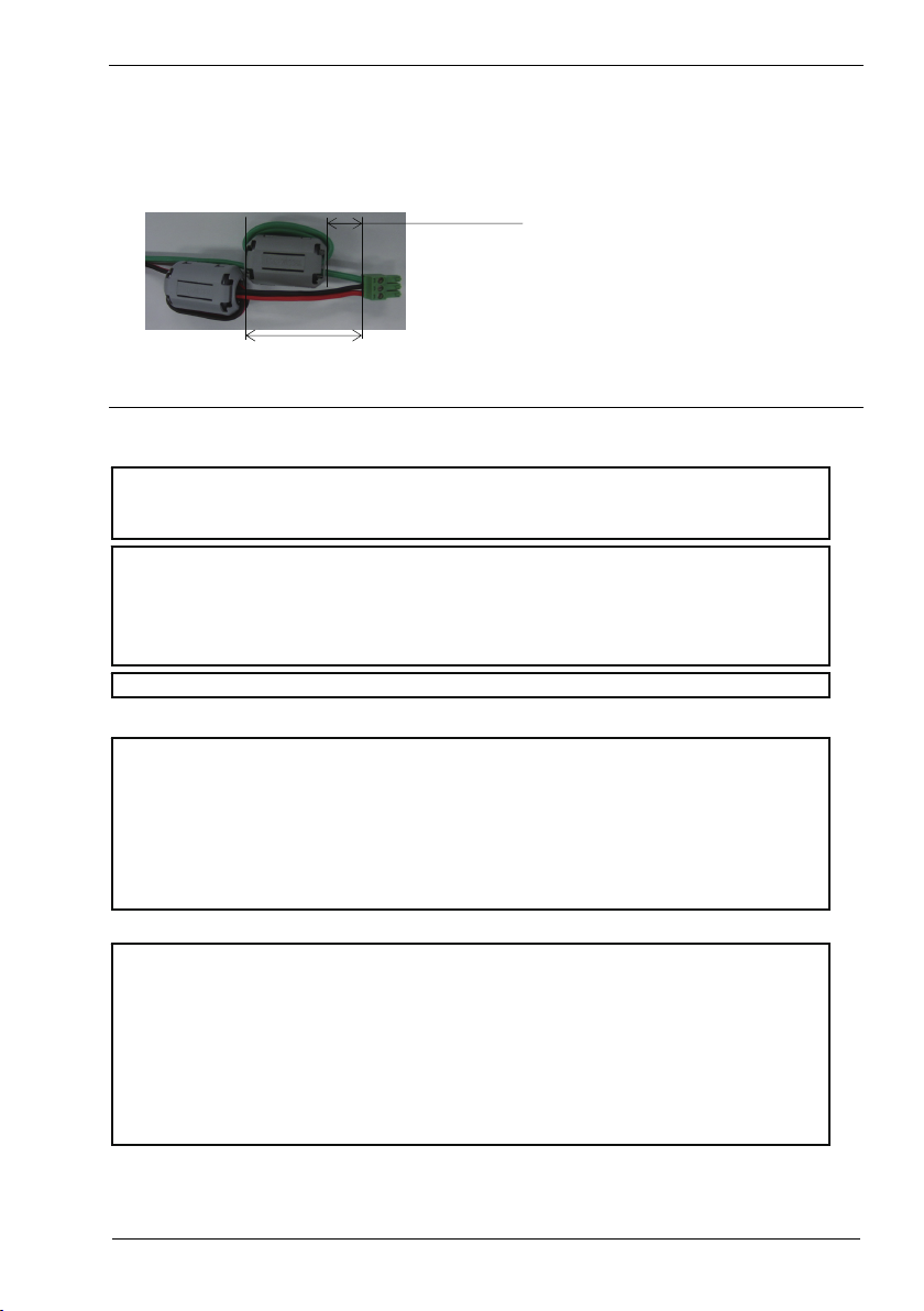
The NZ2WL-US , NZ2WL-EU, and NZ2WL-TW comply with FCC PART15, the R&TTE Directive, and the
NCC Certification when used under the following conditio ns.
- Attach ferrite cores to the power supply line and the FG line.
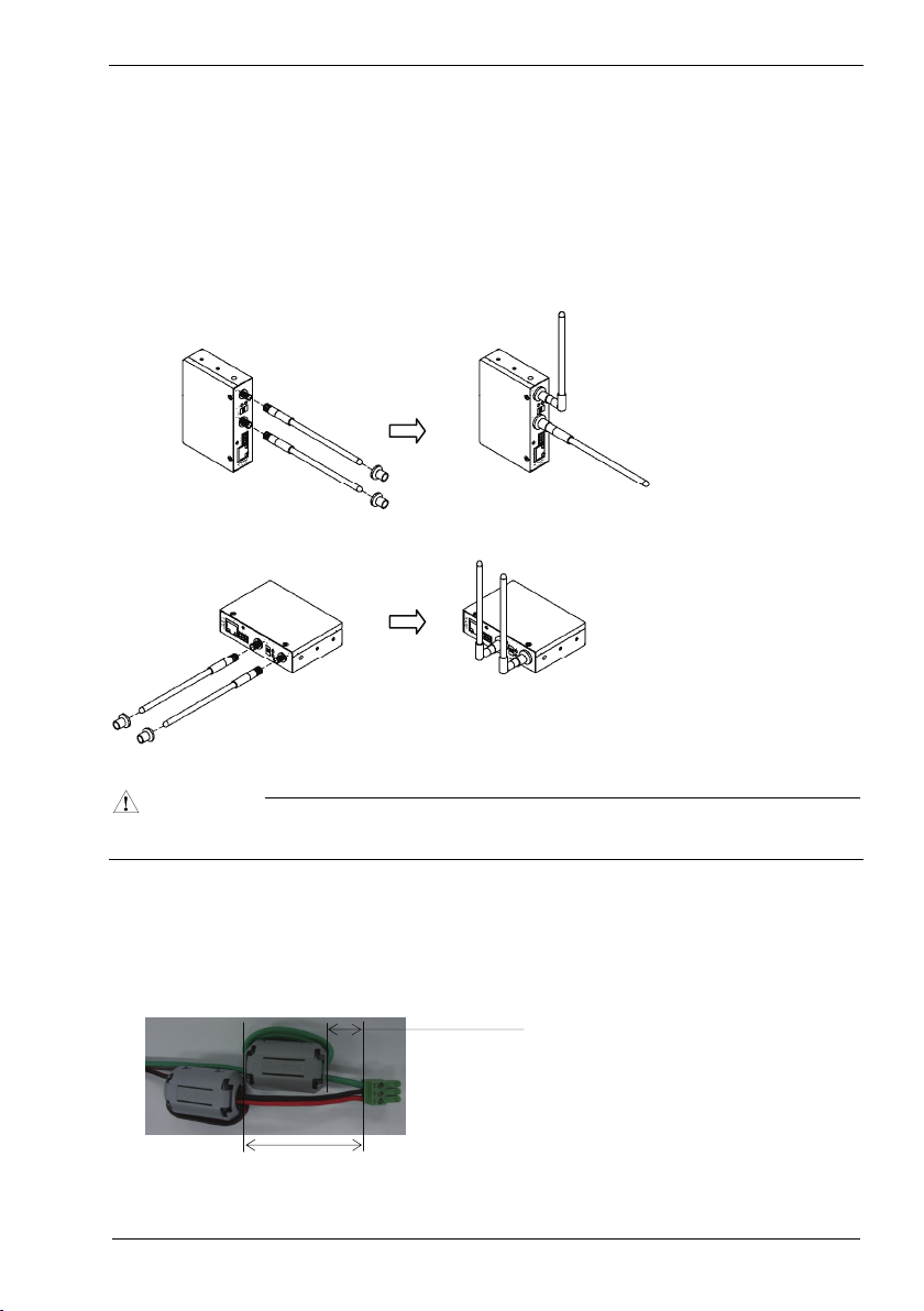
The following picture shows the ferrite cores attached to the cable.
2cm from the EUT
6cm from the EUT
Attach ferrite cores to the FG line (2cm from the EUT) and the power supply line (6cm from the EUT), and turn
the cable three times (wind it twice).
FCC Part 15 Notice
FCC WARNING
Changes or modifications not expressly approved by the party responsible for compliance could void the
user’s authority to operate the equipment.
This transmitter must not be co-located or operated in conjunction with any other antenna or transmitter.
This equipment complies with FCC radiation exposure limits set forth for a controlle d environment and meets
the FCC radio frequency (RF) Exposure Guidelines in Supplement C to OET65. This equipment should be
installed and operated keeping the radiator at least 20cm or more away from person’s body (excluding
extremities: hands, wrists, feet and ankles).
Ferrite cores must be used with the power supply line and FG line to suppress radio frequency interference.
FCC Part 15 Subpart B class A Notice
Note: This equipment has been tested and found to comply with the limits for a Class A digital device,
pursuant to part 15 of the FCC Rules. These limits are designed to provide reasonable protection against
harmful interference when the equipment is operated in a commercial environment. This equipment generates,
uses, and can radiate radio frequency energy and, if not installed and used in accordance with the instruction
manual, may cause harmful interference to radio communications. Operation of this equipment in a
residentia l area is likely to cause harmful interference in which case the user will be required to correct the
interference at his own expense.
FCC Part 15 Subpart E Notice
Operations in the 5.15-5.25GHz band are restricted to indoor usage only.
Compliance with FCC requirement 15.407(c)
Data transmission is always initiate d by software, which is then passed down through the MAC, through the
digital and analog baseband, and finally to the RF chip. Several special packets are initiated by the MAC.
These are the only ways the digital baseband portion will turn on the RF transmitter, which it then turns off at
the end of the packet. Therefore, the transmitter will be on only while one of the aforementioned packets is
being transmitted. In other words, this device automatically discontinue transmission in case of either absence
of information to transmit or operational failure.
Frequecncy tolerance:±30ppm
NZ2WL - xxx
v

Connection to MELSEC Series Equipment
The NZ2WL Series can be connected to various programmable controllers and display units.
Connectable Equipment
The following MELSEC Series equipment can be connected.
Type Model
MELSEC-Q Series Ethernet Interface Module (for 10BASE-T/100BASE-TX) *2
Programmable
Controller
HMI
Motion
Controller
CNC
Software
*1 The manuals of so me of these product s may indic ate that operat ions cannot be g uaranteed w hen connected u sing a
wireless network other than that using this wireless LAN equipment. Before using this product, please read "Note on
Connections" o n the next page.
*2 Before using this product with Ethernet interface modules, please read "Note on Connection with Ethernet Interface
Module” on the next page.
*3 The NZ2WL series can be connected only to the Ethernet part of this module. The NZ2WL series cannot be connected to
the CC-Link IE Fie ld Network part o f this module.
CC-Link IE Field Network Ethernet Adapter Module *3
MELSEC-Q Series CPU Module (with Built-in Ethernet)
Motion Controller Q Serie s Motion CPU Module (for the iQ Platform)
Motion Controller Q Series Stand-Alone Motion Controller
CNC Remote Operating Tool (NC Monitor/NC Explorer)
Industrial Switching HUB
MELSEC-L Series CPU Module
C Controller Module
GOT1000 Series (with Built-in Ethernet)
GOT1000 Series Ethernet Communication Unit
Motion Controller Q Series Motion CPU Module
MITSUBISHI CNC M700/M70 Series
MITSUBISHI CNC M700V/M70V Series
MITSUBISHI CNC C70 Series
GX Works2
MX Component
LCPU Logging Configuration Tool
C Controller Module Setting / Monitoring Tool
MX Sheet
GX LogViewer
GX IEC Developer
PX Developer
PX Developer Moni tor Tool
CW Workbench
GT Works3
MT Works2
*1
NZ2WL - xxx
vi

Note on Connections
CAUTION
- Do not use this product for applications that must transmit or update data regularly or within a
given time period, such as the cyclic transmission of a programmable controller. Transmission
delays cannot be obtained through calculations for Ethernet communications using this product.
- Use this product with the access point and station in visual range of each other (so that the antenna
on one device is visible from the antenna on the other device).
- During an Ethernet connection using wireless LAN, packets may be lost due to the peripheral
environment and equipment location, and the connection may not be as stable as with a wired
Ethernet connection. Be sure to check operations when using this product. Packets may be
frequently lost especially during broadcasts. In this case, use a user application or use UDP or TCP
with a specified IP address for the client.
- If the timer value set for the MELSEC Series equipment connected to this product is large, it may
take time to detect the loss of packets, and communications may appear to have stopped.*1 In this
case, changing the timer value may fix the problem.
- Do not directly connect a MELSEC-Q Series CPU module (with Built-in Ethernet) or a
MELSEC-L Series CPU module to an Ethernet port on a MELSOFT product by wireless LAN
connection.
- For additional restrictions and notes on using a wireless LAN connection, see the manual of the
MELSEC products to which this product is connected.
- This product cannot be directly connected to a CC-Link IE Field Network. A wired Ethernet
connection must be made using an optional CC-Link IE Field Network Ethernet adapter module.
- If a problem occurs, but there is nothing wrong with the settings or usage of MELSEC products
connected to this product or the Ethernet wire, there may be a problem with the setup or settings of
this product. Refer to "Chapter 7 Troubleshooting" and check the operations of this product. You
can also refer to the user's manuals of the MELSEC products connected to this product.
*1 For example, the default value of the response monitoring timer of the Ethernet Interface Module is 30 seconds, so it
takes 30 seconds to detect packet losses.
Note on Connection with Ethernet Interface Module
- When connecting this product with an Ethernet interface module, the COM.ERR.LED of the
Ethernet interface module may turn on (error code: C04B
packet loss. Communication can be performed with the COM.ERR.LED turned on. However,
check carefully that the system works as expected.
For how to turn off the COM.ERR.LED, refer to "Q Corresponding Ethernet Interface Module
User's Manual (Basic)".
- When the COM.ERR.LED frequently turns on, the following operations may reduce the frequency:
- Use TCP on the connection.
- Enable TCP segmentation*2.
To enable TCP segmentation, set 5B4
(address: 1E
) and execute reinitialization.
H
to the TCP Maximum Segment Transmission setting area
H
For reinitialization, refer to "Q Corresponding Ethernet Interface Module User's Manual (Basic)."
*2 The TCP Maximum Segment Transmission setting area can be configured only for the Ethernet in terface modules
(QJ71E71-100) wi th function version B or later, whose fi rst five digits of the serial nu mber are 05051 or later.
When the setting is changed to "Enable TCP Maximum Segment Size Option transmission, there are restrictions on
combination with the MELSOFT products. Refer to "Q Corresponding Ethernet Interface Module User's Manual
(Basic)".
NZ2WL - xxx
, etc.) due to some reasons such as
H
vii

CONDITIONS OF USE FOR THE PRODUCT
(1) Mitsubishi programmable controller ("the PRODUCT") shall be used in conditions;
i) where any problem, fault or failure occurring in the PRODUCT, if any, shall not lead to any
major or serious accident; and
ii) where the backup and fail-safe function are systematically or automatically provided outside of
the PRODUCT for the case of any problem, fault or failure occurring in the PRODUCT.
(2) The PRODUCT has been designed and manufactured for the purpose of being used in general
industries.
MITSUBISHI SHALL HAVE NO RESPONSIBILITY OR LIABILITY (INCLUDING, BUT
NOT LIMITED TO ANY AND ALL RESPONSIBILITY OR LIABILITY BASED ON
CONTRACT, WARRANTY, TORT, PRODUCT LIABILITY) FOR ANY INJURY OR DEATH
TO PERSONS OR LOSS OR DAMAGE TO PROPERTY CAUSED BY the PRODUCT THAT
ARE OPERATED OR USED IN APPLICATION NOT INTENDED OR EXCLUDED BY
INSTRUCTIONS, PRECAUTIONS, OR WARNING CONTAINED IN MITSUBISHI'S USER,
INSTRUCTION AND/OR SAFETY MANUALS, TECHNICAL BULLETINS AND
GUIDE LINES FOR the PRODUCT.
("Prohibited Application")
Prohibited Applications include, but not limited to, the use of the PRODUCT in;
- Nuclear Power Plants and any other power plants operated by Power companies, and/or any
other cases in which the public could be affected if any problem or fault occurs in the
PRODUCT.
- Railway companies or Public service purposes, and/or any other cases in which establishment
of a special quality assurance system is required by the Purchaser or End User.
- Aircraft or Aerospace, Medical applications, Train equipment, transport equipment such as
Elevator and Escalator, Incineration and Fuel devices, Vehicles, Manned transportation,
Equipment for Recreation and Amusement, and Safety devices, handling of Nuclear or
Hazardous Materials or Chemicals, Mining and Drilling, and/or other applications where there
is a significant risk of injury to the public or property.
NZ2WL - xxx
viii

Terminology/Abbreviations
The following terms and abbreviations are used in this manual for convenience.
Full term Term used in this manual
All five NZ2WL models (NZ2WL-US, NZ2WL-EU, NZ2WL-CN,
NZ2WL-KR, NZ2WL-TW)
NZ2WL-US (for U.S.A.) US
NZ2WL-EU (for Europe) EU
NZ2WL-CN (for China) CN
NZ2WL-KR (for Korea) KR
NZ2WL-TW (for Taiwan) TW
Access point only supported (AP only)
Station only supported (ST only)
A device with the wireless functi on Wireless terminal
Personal computer PC
NZ2WL-xxx
Speed Notation
The link speed values (such as 54 Mbps) of the transmission rate used in this manual and setting screens
are the theoretical maximum values of the wireless LAN standard and do not indicate the actual data
transmission speed.
NZ2WL - xxx
ix
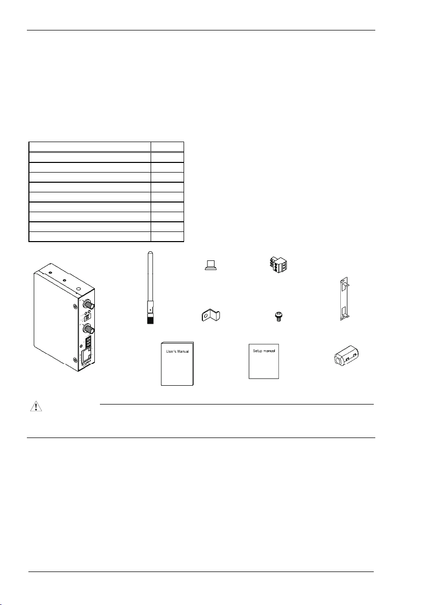
Packing List
Thank you for purchasing this Mitsubishi product.
The product package should contain the items listed below.
Use the following list to confirm the contents of the product package.
If you discover any damaged or missing item, contact your local authorized dealer.
Contents
Name Pcs.
Main unit (NZ2WL-xxx) 1
Antenna, rubber cap for a ntenna 2
User’s Manual 1
Power terminal connector 1
Retent ion b racket 1
Mounting bracket 1
Bracket screw M3 x 6 3
Setup manual (CN,KR,T W only) 1
Ferrite core (US,EU,TW only) 2
Antenna x 2
Rubber cap for
antenna × 2
Retention bracket
Power terminal
Bracket screw M3 x 6 × 3
Mounting bracket
Main unit
CAUTION
To operate this product, a power supply (12-24VDC±5%) is required separately. For power supply, see Chapter 2,
Part Names and Settings, “ Power Supply”.
User’s Manual
Setup manual
(CN, KR, TW o nly)
Ferrite core × 2
(US, EU, TW only)
- This document, in whole or in part, may not be reproduced without permission.
- This document is subject to change without notice at any time.
- While we are doing our best to ensure this document has no error,
should you have any questions or find any omissions or similar, cons ult
- MS, Microsoft, Windows, Windows NT, and MS-DOS are registered trademarks or trademarks of Microsoft
Corporation in the U.S.A. and other countries.
Mozilla, Fire fox, and the Firefox logo are trademarks or registered trade marks of Mozilla Foundation in the U.S.
and other countries.
All other company na mes and products used in this manual are trade marks or registered trademarks of their
respective companies. This manual does not use the symbols such as ™, ®, and ©.
your local authorized dealer.
NZ2WL - xxx
x

Table of Contents
Packing List......................................................................................................................................... x
1. BEFORE USING THE PRODUCT 1
Overview............................................................................................................................................. 1
Features ........................................................................................................................................ 1
Environment................................................................................................................................. 3
Inspection ..................................................................................................................................... 3
Storage ......................................................................................................................................... 3
Disposal........................................................................................................................................ 3
2. SETUP 4
Part Names and Functions................................................................................................................... 4
LED display ................................................................................................................................. 4
DIP switches................................................................................................................................. 5
Connectors.................................................................................................................................... 6
Checking the Network Addresses ....................................................................................................... 6
Attaching the Antennas....................................................................................................................... 7
FCC PART15, R&TTE Directive, NCC Certification addenda (for USA, Europe, and Taiwan only) . 7
Power Supply ...................................................................................................................................... 8
Grounding the NZ2WL....................................................................................................................... 9
Installation........................................................................................................................................... 9
Using Mounting Brackets............................................................................................................. 9
Wired LAN Connection .................................................................................................................... 10
3. CONNECTING TO DEVICES AND SETUP METHODS 11
Setup Methods................................................................................................................................... 11
Preparation before Setup ................................................................................................................... 11
Setup Using Web Browser ................................................................................................................ 12
Setting the Browser.................................................................................................................... 12
Connecting to This Product Using Web Browser ......................................................................13
Setup Using Web Browser .........................................................................................................14
Setup Using TELNET....................................................................................................................... 15
Connecting to the Product Using TELNET................................................................................ 15
Setup Using TELNET................................................................................................................ 17
TELNET Key Operation ............................................................................................................18
NZ2WL - xxx
xi

4. WIRELESS LINK MODE AND WIRELESS LAN FUNCTION 19
Wireless Link Mode.......................................................................................................................... 19
Standard Infrastructure Mode..................................................................................................... 19
Compatible Infrastructure Mode ................................................................................................20
Advanced Infrastructure Mode................................................................................................... 21
Comparison of Main Functions.................................................................................................. 22
Installation in a Network ................................................................................................................... 24
Features of the Wireless Network .............................................................................................. 24
Operating Environment and Radio Waves ................................................................................. 25
Constructing a Network.............................................................................................................. 26
5. SETUP AND STATUS DISPLAY 27
Settings.............................................................................................................................................. 27
◆Basic setting ........................................................................................................................... 27
◆Ethernet ..................................................................................................................................29
◆Wireless LAN......................................................................................................................... 30
◆IEEE802.1X ...........................................................................................................................39
◆Extension................................................................................................................................ 41
◆SNMP ..................................................................................................................................... 44
◆VLAN..................................................................................................................................... 46
◆Log ......................................................................................................................................... 47
Status Display.................................................................................................................................... 48
6. MAINTENANCE 55
Maintenance Tool.............................................................................................................................. 55
Log File Collection............................................................................................................................55
Collecting Log Files Using FTP................................................................................................. 55
Saving a Setting File ......................................................................................................................... 56
Saving Setting File Using FTP...................................................................................................56
Restoring the Software Settings ........................................................................................................ 57
Restore Settings Using FTP ....................................................................................................... 57
Time Setting...................................................................................................................................... 58
Initialization ......................................................................................................................................58
Using TELNET .......................................................................................................................... 58
Using a Web Browser................................................................................................................. 59
Using the DIP Switch (INIT) .....................................................................................................59
NZ2WL - xxx
xii

7. TROUBLESHOOTING 60
When Communication Fails.............................................................................................................. 60
Setup Screen Unavailable on Web Browser...................................................................................... 61
When the Product Does Not Start ..................................................................................................... 61
8. APPENDIX 62
BSHardware Setup ............................................................................................................................ 62
Initial Setting..................................................................................................................................... 62
Specifications .................................................................................................................................... 66
Software Specifications..................................................................................................................... 67
Installation Environment Requirements (Environmental Specifications)......................................... 67
External Dimensions ......................................................................................................................... 68
Pin Layout of LAN Port.................................................................................................................... 68
WARRANTY.................................................................................................................................... 69
R&TTE Directive.............................................................................................................................. 71
NZ2WL - xxx
xiii

MEMO
NZ2WL - xxx
xiv

1. Before Using the Product
1. Before Using the Product
This chapter provides information you should know before using the product.
Overview
The NZ2WL-xxx is a wireless LAN adapter that conforms to IEEE 802.11a/b/g standards of various
countries and features a wide input power supply (12 to 24 VDC) and can be configured either as an
access point or station.
This product features WPA2/WPA security functions (AP only), multi-client function (ST only),
extended range (XR) function, Super A/G function, Wireless Distribution System (WDS) function,
Quality of Service (QoS) function, and other functions.
Please read this manual carefully before using the product.
The NZ2WL Series uses a wireless LAN chip set manufactured by Atheros Communications Inc. The main board,
firmware, and the enhanced feature have been developed and equipped.
Features
The wireless LAN adapter that conforms to IEEE 802.11a/b/g standards and can be configured either
■
as an access point or station.
This product conforms to IEEE 802.11a/b/g standards, the channel can be set depending on the country,
and it can be configured either as an access point or station.
High-level security features equipped *1
■
The product is equipped with WPA2/WPA, the latest security standards. The product also supports
IEEE 802.1X authentication in addition to the AES, AES-OCB, and WEP (64/128/152-bit) encryption.
Original encryption functions are also equipped. Those functions include WSL, an original encryption
technology, that can be used with WPA2/WPA or WEP as well as MAC address filtering, ESSID hide,
and ANY ID reject.
IP tunneling function equipped *2
■
An IP tunneling function enables communication even at roaming destinations beyond the router range
without changing the network configuration.
Offering three wireless connection modes according to network configurations
■
Standard *3 : Mode to use the features unique to the NZ2WL Series, such as IP tunneling and
WSL
Compatible *3 : Mode for heterogeneous use along with other vendors' wireless equipment
supporting Wi-Fi *4
Advanced *3 : Mode to allow wireless LAN terminals both in standard mode and compatible
mode to be connected on the network at the same time (only AP)
XR function equipped *5
■
The XR (eXtended Range) function developed by Atheros Communications Inc. greatly extends the
range of the wireless LAN communication area. This is useful for providing a stable connection such as
at locations where radio wave interference may occur or where obstacles create "dead zones".
Super A/G feature equipped
■
The product is equipped with super A/G feature that improves communication speed. The
communication speed of the wireless LAN can be increased between supported models.
NZ2WL - xxx
1

1. Before Using the Product
WDS feature equipped *6
■
Up to six units can be connected wirelessly between access points.
QoS support
■
Bands are secured for specific communication, such as VoIP, and communication quality is guaranteed.
SNMP agent feature equipped
■
The feature enables network management using SNMP supported network management software.
Protect Mode available when using IEEE802.11g
■
Stable communications are enabled even when IEEE802.11b-compliant products are also used.
Communication speeds are improved for IEEE802.11g-compliant products.
Others
■
Introducing the Diversity Method with a built-in chip antenna.
-
Easy configuration and management using a Web browser. Various maintenance methods are
-
available according to systems and applications, including FTP commands and TELNET.
*1 WPA2/WPA, IEEE 802.1X authentication, MAC address filtering, ESSID hide, and ANY ID reject can be used only when the product
is configured as an acces s point.
*2 The IP tunne ling function can be used in sta ndard wireless connect ion mode.
*3 The official names are as fo llows:
Standard
Compa tible
Advanced
*4 Compatible mode does not guarantee int er-connect ivity with other vendors' Wi-F i products.
*5 The XR feature can be used o nly when bot h of the access po int and stat ion in the wireles s LAN support the XR feature.
*6 The WDS function is available only when the product is configured as an access point.
Standard Infrastructure
•••
Compa tible Infra struct ure
•••
Advanced Infrast ructure
•••
NZ2WL - xxx
2

1. Before Using the Product
Environment
Use this product in the following environment.
If used under environmental conditions exceeding these ranges, the board may overheat, malfunction, or
cause a failure.
Operating ambient temperature
0 - 50ºC
Operating ambient humidity
10 - 90%RH (No condensation)
Corrosive gases
None
Floating dust particles
Small amounts (non excessive)
Inspection
Inspect the product periodically as follows to use it safely.
Storage
When storing this product, keep it in its original packing form.
(1) Put the main unit in the storage bag.
(2) Wrap it in the packing material, then put it in the box.
(3) Store the package at room temperature at a place free from direct sunlight, moisture, shock,
vibration, magnetism, and static electricity.
Disposal
When disposing of the product, follow the disposal procedures stipulated under the relevant laws and
municipal ordinances.
NZ2WL - xxx
3
2. Setup
2. Setup
The antenna must be mounted and installed properly before configuring this product. Follow the setup
procedure for the product shown below.
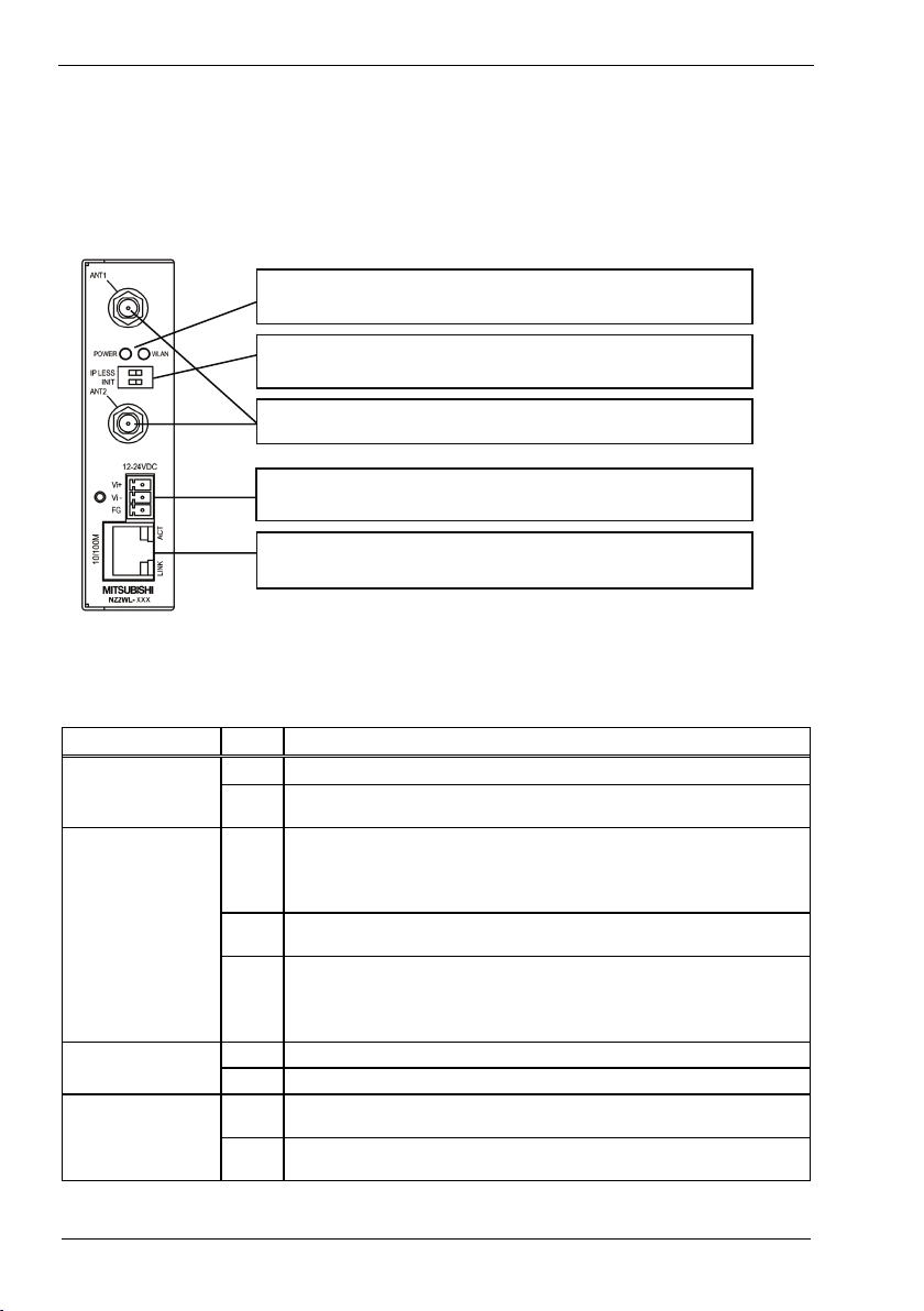
Part Names and Functions
LED:
Indicates the statu s of the power supply, wired L AN and wireless LAN.
Refer to Tables 2.1 - 2. 3 for details.
DIP switch:
Used for initia lizat ion a nd for ope ratio n in IP- less mo de.
See Table 2.4 for the setting method.
Antenna connectors:
Connect to the a ntennas. Conne ct supplied dipo le antennas to these connecto rs.
Power supply connector:
Used to supply power to the product.
Also used to gro und the product.
LAN port:
Connects to a hub o r PC through 10-BASE -T/100-BASE-TX.
Also displays the wired LAN connection statu s using the LINK and ACT LEDs.
Figure 2.1. Part names
LED display
Table 2.1. LED Displays during Normal Operation
LED name Status LED display
Indicate s that the device is operating.
POWER
WLAN
LINK (LAN)
ACT (LAN)
ON
Indicate s that the device is being started (going to opera te after the power
Flashing
switch was turned on)
When the product is configured as an access point, the LED being ON indicates
that one or more stations are logged in the product.
ON
When the product is configured as a station, the LED being ON indicates that the
product is logged in an access point.
Indicate s data is being transmitted to or received from th e device connected
Flashing
through wireless LAN.
When the product is configured as an access point, the LED being OFF indicates
that no station is logged in the product.
OFF
When the product is configured as a station, the LED being OFF indicates that the
product is not logged in an access point.
Indicates that a wired LAN has been connected.
ON
Indicate s that a wired LAN is not connecte d.
OFF
Indicate s that the product is transmitting/receiving data to/fro m the conne cted
Flashing
terminal through wired LAN.
Indicate s that the product is not transmitting/receiving data to/from the connected
OFF
terminal through wired LAN.
NZ2WL - xxx
4
2. Setup
Table 2.2. During File Write
LED name Status LED display
POWER
WLAN
*1 Except writing of log files (no flashing)
Flashing
simultaneously
File write in progress *1
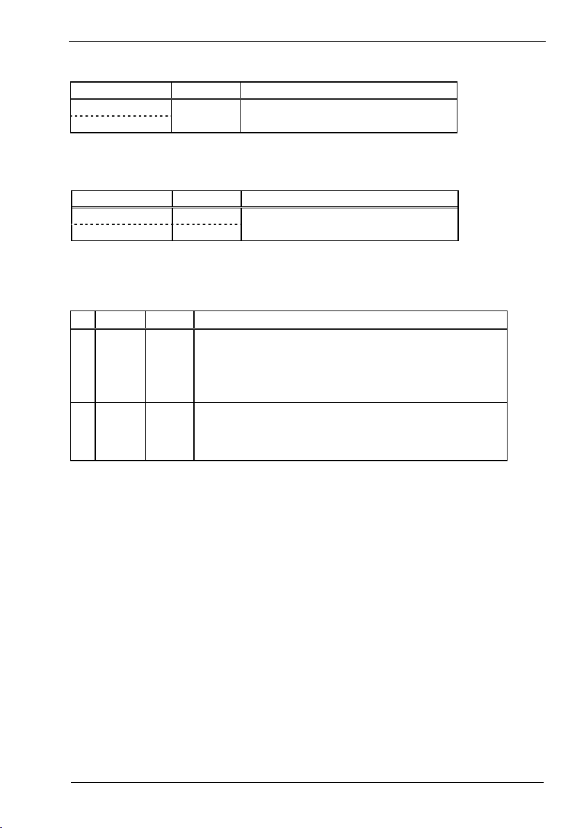
Table 2.3. Error Display
LED name Status LED display
POWER Flashing twice
WLAN ON
Wireless LAN error
DIP switches
Table 2.4. DIP Switches
ON OFF Operation / function
Turning on this switch flashes the POWER and WLAN LEDs.
1 INIT -
2 IP LESS -
*1 The flashing continues for a little while after the product is switched off during initialization by switching
on and off the INIT switch. This indicates internal memory files are being deleted. The internal memory
files may be da maged and the product may not start up properly if the power is swi tched off before the
flashing stops. Always reboot th e product after the flashing stops.
If the switch is tu rned off before the LEDs change their status from flashing to
ON (abou t 3 seconds), all the settings are restored to the defaul t settings after
the product is started next time. Reboot the produ ct after the LEDs stop
flashing. *1
Turning on this switch allows the product to operate without the IP address
setting. The switch is used when an IP address is n ot allocated to the product
at the setup of a station. In this case, the TELNET, FTP, settings by Web
browser, and SNMP agent function cannot be used.
NZ2WL - xxx
5
2. Setup
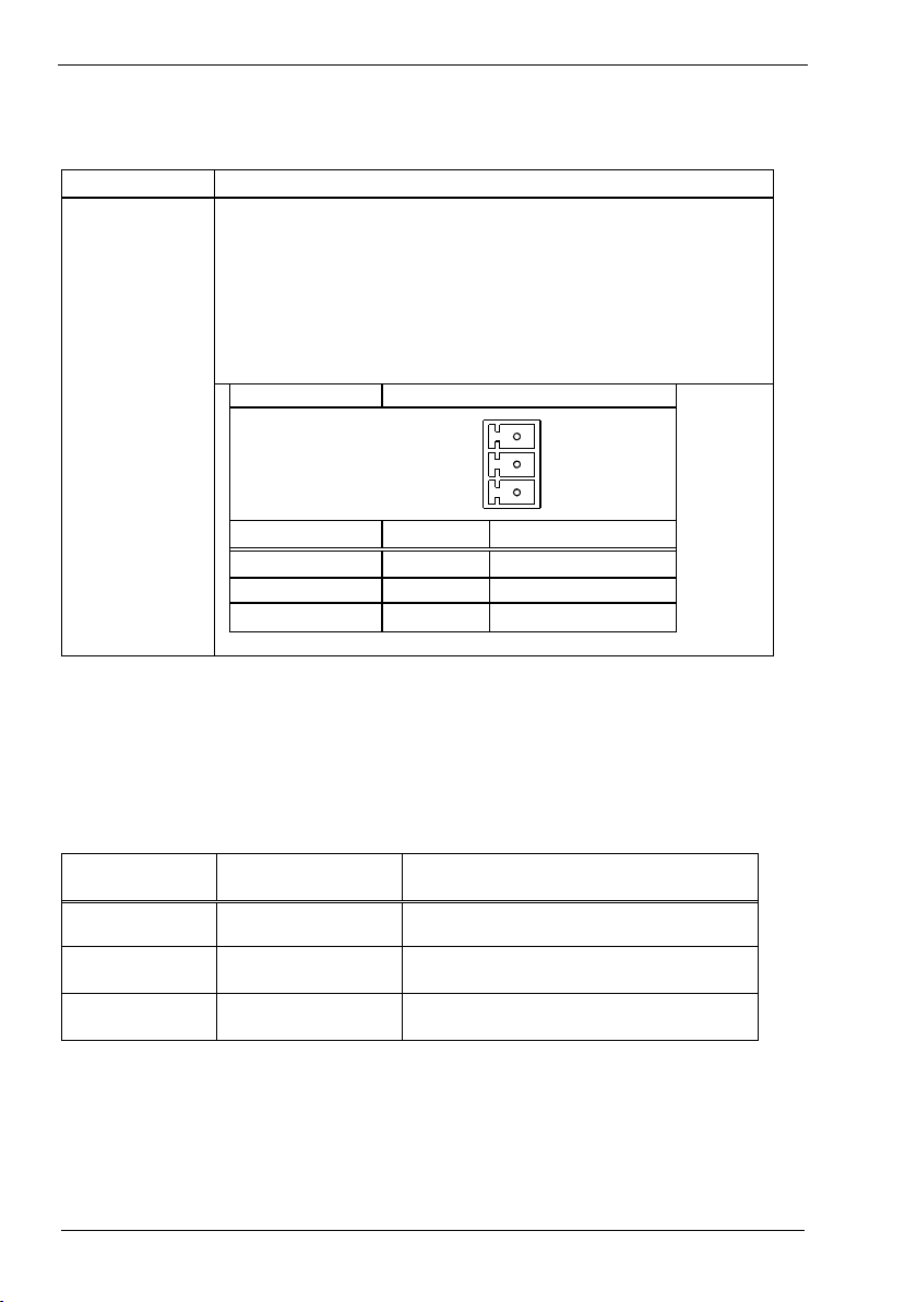
Connectors
Table 2.5. Power Connectors
Name Function
Power connector
Power terminal connector (included in the package): MC1,5/3-ST-3,5 (made by Phoenix
Contact Inc.)
The applicable cable is AWG28-16. (The cable length must meet the power supply
specifications.)
The applicable bar solderless terminals are AI0,25-6BU, AI0,34-6TQ and AI0,5-6WH
(made by Phoenix Contact Inc.)
Secure the connector with a reten tion bracket. C onnect the power cable to the power
terminal connector by screw connection.
The fastening torque range is 0.22 to 0.25Nm.
Power connector MC1,5/3-G-3,5 (Phoenix Contact)
12-24VDC
Vi+
Vi-
FG
Pin number Signal Description
1 Vi+ Power (12-24VDC±5%)
2 Vi- Power (GND)
3 FG Frame G rand
Checking the Network Addresses
The Ethernet (wired LAN), wireless LAN MAC address and IP address are defined on the housing
sticker on the side of this product. Write down the MAC addresses for Ethernet and wireless LAN in the
following table as they are device-individual values and may be required for future setup.
Table 2.6. Network Address
Description on the
housing sticker
IP: Default IP Address
C: Ethernet MAC Address
W: Wireless MAC Address
NZ2WL - xxx
6
Explanation Address
2. Setup
Attaching the Antennas
Use this product with the antennas included. The following describes how to attach the supplied dipole
antennas.
(1) Straighten both the antennas, as shown below, and attach them to the antenna connectors on the
main unit. The antennas screw onto the antenna connector. Adjust the position of the bending part
of the antennas taking into consideration how the antennas will be oriented. Next, place the
supplied rubber caps over the antennas and cover the antenna connectors.
(2) Bend the antennas to the desired angles. The antennas can also be used straight. Change the angle as
needed depending on the position of the unit.
<Example of vertical position>
(1)
<Example of horizontal position>
(2)
(2) (1)
Figure 2.2. Attaching the Antennas
CAUTION
Using the product without connecting the antennas to the antenna connectors may cause the product
to malfunction. Be sure to use the product with the antennas connected.
FCC PART15, R&TTE Directive, NCC Certification addenda
(for USA, Europe, and Taiwan only)
The NZ2WL-US , NZ2WL-EU, and NZ2WL-TW comply with FCC PART15, the R&TTE Directive, and the
NCC Certification when used under the following conditio ns.
- Attach ferrite cores to the power supply line and the FG line.
The following picture shows the ferrite cores attached to the cable.
Attach ferrite cores to the FG line (2cm from the EUT) and the power supply line (6cm from the EUT), and turn
the cable three times (wind it twice).
NZ2WL - xxx
6cm from the EUT
2cm from the EUT
7
2. Setup
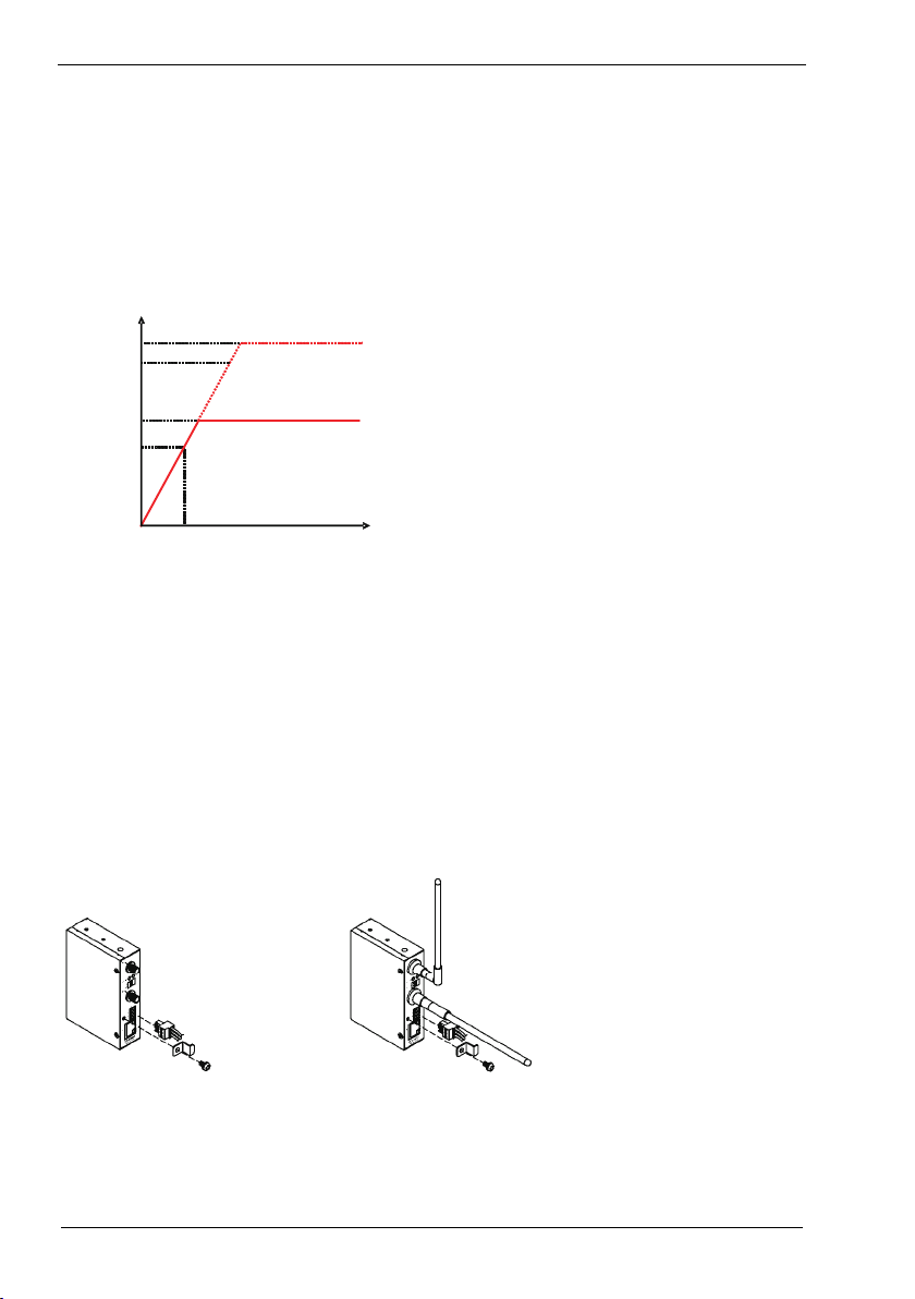
Power Supply
- The input voltage range of this product is 12 to 24 VDC ±5%.
Using a power supply outside of that range may cause a malfunction or accident.
- Connect the cables correctly to the Vi+ (12 to 24 VDC ±5%), Vi- (GND), and FG connectors.
- Use a power source that starts up within the input voltage range of 11.4 VDC or higher within 24
ms. Using a power supply that does not satisfy these conditions may cause a malfunction or
accident.
(V)
Input
voltage
Figure 2.3. Power Supply Input Time
- The AC/DC power supply connected to the product must be CE-marked.
- Ground the FG terminal.
- Recommended power supply: PS5R-SF24 (made by IDEC Corporation)
25.2
24
12
11.4
24
Time
(ms)
Attaching a retention bracket
Plug in the power terminal connector to the power connector and attach the retention bracket using a
bracket screw. The tightening torque of the bracket screw is 0.588 Nm.
Figure 2.4. Attaching a Retention Bracket
NZ2WL - xxx
8
2. Setup
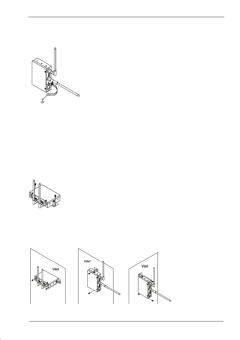
Grounding the NZ2WL
Connect the cables to the applicable connectors. Process the cables as needed and ground the product.
Figure 2.5. Grounding the NZ2WL
Installation
Using Mounting Brackets
Mounting on a Desktop (Horizontally)
When the product is used horizontally, it can be mounted on a desk or other surfaces using brackets.
Attach the product and brackets using the supplied bracket screws (tightening torque: 0.588 Nm), as
shown below, and place the side with the brackets down. Then secure the brackets on the desk using
tapping screws.
Figure 2.6. Mounting the Product on a Desk
Mounting on a Wall
The product can be mounted on a wall using mounting brackets. Attach the product and brackets using
the supplied bracket screws (tightening torque: 0.588 Nm), as shown below, and then secure the
brackets to the wall using tapping screws.
Figure 2.7. Mounting the Product on a Wall
NZ2WL - xxx
9
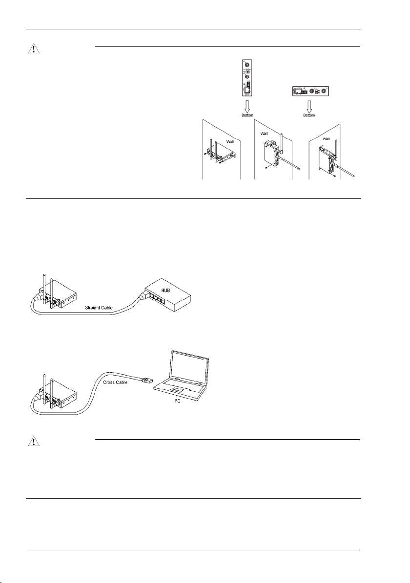
2. Setup
CAUTION
When mounting the product on a desk or wall,
place the product down with one of the
orientations shown to the right.
When mounting the product vertically, orient
the product with the LAN port on the bottom.
When mounting the product horizontally,
orient the product with the WLAN LED on the
bottom.
When mounting the product to a wall, secure
the rear of the product or the side of the
product closest to the WLAN LED to the wall.
Place the product as indicated above when
mounting it on the wall.
Wired LAN Connection
Connect the LAN cable to the LAN port on the product.
A cross cable is used to connect the product to the UP-LINK port of a PC or HUB. A straight cable is
used to connect the product to the normal port of a HUB.
Figure 2.8. Wired LAN Connection
CAUTION
The cable connecting the product to a hub, PC, or other device must not exceed 100 m.
-
Use a CAT-5 or CAT-6 STP cable.
-
This product cannot be used with IEEE 802.3af or other infrastructure that supplies power over an
-
Ethernet cable (Power Over Ethernet (PoE)).
NZ2WL - xxx
10

3. Connecting to Devices and Setup Methods
3. Connecting to Devices and Setup
Methods
This product is set up via a network using a Web browser or TELNET. Follow the setup procedure
below once the product is set up.
Setup Methods
Although the NZ2WL-xxx can be set up precisely to construct an advanced wireless LAN environment,
there are two different setup methods available: web browser and TELNET.
Web browser
Settings are easy with a graphical display and a help function.
-
TELNET
This terminal setting uses TELNET.
-
Only text is displayed, but settings are easy and quick.
-
Preparation before Setup
Since the product is set up via network, use a personal computer that can be connected to the network.
Connect the personal computer to the network and use a Web browser or TELNET for setting.
Connecting the product for the first time
(1) Connect this product to PC on a wired LAN.
(2) Select an IP address 10.XXX.XXX.XXX (e.g. 10.0.0.1) for the PC, which is not the same address
as for this product. And then set the subnet mask to 255.0.0.0.
Windows:
Click [Start] - [Control Panel] - [Network Connection], and then right-click the icon for local area
connection to open up the [Properties] screen. Select [Internet Protocol (TCP/IP)] from the
[General] tab and click [Properties]. Set up the IP address and subnet mask, and if necessary,
default gateway and DNS server on the opened [Internet protocol (TCP/IP) properties] window.
Changing the settings
(1) Connect this product to PC on a wired LAN.
(2) Set the network address of the PC to the same network address as for this product.
NZ2WL - xxx
11
 Loading...