

Mitsubishi Electric NZ2MFB2-16A, NZ2MFB1-32T, NZ2MFB1-32TE1, NZ2MFB1-32DT, NZ2MFB1-32DTE1 User Manual
...Page 1

CC-Link IE Field Network Basic
Remote
-NZ2MFB2-16A
-NZ2MFB1-32D
-NZ2MFB2-16R
-NZ2MFB1-32T
-NZ2MFB1-32TE1
-NZ2MFB1-32DT
-NZ2MFB1-32DTE1
I/O Module User's Manual
Page 2

Page 3
SAFETY PRECAUTIONS
WARNING
Indicates that incorrect handling may cause hazardous conditions, resulting in
death or severe injury.
CAUTION
Indicates that incorrect handling may cause hazardous conditions, resulting in
minor or moderate injury or property damage.
(Read these precautions before using this product.)
Before using this product, please read this manual and the relevant manuals carefully and pay full attention to safety to handle
the product correctly.
The precautions given in this manual are concerned with this product only. For the safety precautions of the programmable
controller system, refer to the user's manual for the CPU module used.
In this manual, the safety precautions are classified into two levels: " WARNING" and " CAUTION".
Under some circumstances, failure to observe the precautions given under " CAUTION" may lead to serious
consequences.
Observe the precautions of both levels because they are important for personal and system safety.
Make sure that the end users read this manual and then keep the manual in a safe place for future reference.
[Design Precautions]
WARNING
● When a communication failure occurs in the network, data in the CPU module on the master station
are held. Check the data link status of each station stored in the special register (SD) and configure an
interlock circuit in the program to ensure that the entire system will operate safely.
● When the module is disconnected due to a communication failure in the network or the CPU module is
in the STOP state, all outputs are held or turned off according to the function setting switch setting.
Configure an interlock circuit in the program to ensure that the entire system will always operate
safely even in such a case. If not, an accident may occur due to an incorrect output or malfunction.
● Outputs may remain on or off due to a failure of the module. Configure an external circuit for
monitoring output signals that could cause a serious accident.
● Do not use any "use prohibited" signals as a remote I/O signal since they are used by the system. Do
not write any data to the "use prohibited" areas in the remote register. Doing so may result in an
accident due to an incorrect output or malfunction.
[Design Precautions]
CAUTION
● Do not install the control lines or communication cables together with the main circuit lines or power
cables. Keep a distance of 100mm or more between them. Failure to do so may result in malfunction
due to noise.
● During control of an inductive load such as a lamp, heater, or solenoid valve, a large current
(approximately ten times greater than normal) may flow when the output is turned from off to on.
Therefore, use a module that has a sufficient current rating.
1
Page 4
[Installation Precautions]
WARNING
● Shut off the external power supply (all phases) used in the system before mounting or removing a
odule. Failure to do so may result in electric shock or cause the module to fail or malfunction.
m
[Installation Precautions]
CAUTION
● Use the module in an environment that meets the general specifications in this manual. Failure to do
o may result in electric shock, fire, malfunction, or damage to or deterioration of the product.
s
● Do not directly touch any conductive parts and electronic components of the module. Doing so ca
c
ause malfunction or failure of the module.
● Securely connect the cable connectors. Poor contact may cause malfunction.
[Wiring Precautions]
WARNING
n
● Shut off the external power supply (all phases) used in the system before wiring. Failure to do so may
esult in electric shock or cause the module to fail or malfunction.
r
2
Page 5

[Wiring Precautions]
CAUTION
● Individually ground the FG terminal of the programmable controller with a ground resistance of 100
ohms or less. Failure to do so may result in electric shock or malfunction.
● Tighten any unused terminal screws within the specified torque range. Undertightening can cause a
short circuit due to contact with a solderless terminal.
● Use applicable solderless terminals and tighten them within the specified torque range. If any spade
solderless terminal is used, it may be disconnected when a terminal block screw comes loose,
resulting in failure.
● Check the rated voltage and terminal layout before wiring to the module, and connect the cables
correctly. Connecting a power supply with a different voltage rating or incorrect wiring may cause a fire
or failure.
● Tighten the terminal block screws within the specified torque range. Undertightening can cause short
circuit, fire, or malfunction. Overtightening can damage the screw and/or module, resulting in drop,
short circuit, fire, or malfunction.
● Prevent foreign matter such as dust or wire chips from entering the module. Such foreign matter can
cause a fire, failure, or malfunction.
● Place the cables in a duct or clamp them. If not, dangling cable may swing or inadvertently be pulled,
resulting in damage to the module or cables or malfunction due to poor contact.
● Do not install the control lines or communication cables together with the main circuit lines or power
cables. Keep a distance of 100mm or more between them. Failure to do so may result in malfunction
due to noise.
● When disconnecting the cable from the module, do not pull the cable by the cable part. For the cable
with connector, hold the connector part of the cable. For the cable connected to the terminal block,
loosen the terminal screw. Pulling the cable connected to the module may result in malfunction or
damage to the module or cable.
● When an overcurrent caused by an error of an external device or a failure of the programmable
controller flows for a long time, it may cause smoke and fire. To prevent this, configure an external
safety circuit, such as a fuse.
● Mitsubishi Electric programmable controllers must be installed in control panels. Wiring and
replacement of a module must be performed by qualified maintenance personnel with knowledge of
protection against electric shock. For wiring methods, refer to "INSTALLATION AND WIRING" in this
manual.
3
Page 6
[Startup and Maintenance Precautions]
WARNING
● Do not touch any terminal while power is on. Doing so will cause electric shock or malfunction.
● Shut off the external power supply (all phases) used in the system before cleaning the module or
retightening the terminal block screws or connector screws. Failure to do so may cause the module to
fail or malfunction.
[Startup and Maintenance Precautions]
CAUTION
● Do not disassemble or modify the module. Doing so may cause failure, malfunction, injury, or a fire.
● Do not drop or apply strong shock to the module. Doing so may damage the module.
● Shut off the external power supply (all phases) used in the system before mounting or removing a
module. Failure to do so may cause the module to fail or malfunction.
● After the first use of the product, do not connect/remove the terminal block more than 50 times (IEC
61131-2 compliant). Exceeding the limit may cause malfunction.
● Before handling the module or connection cables, touch a conducting object such as a grounded
metal to discharge the static electricity from the human body. Failure to do so may cause the module
to fail or malfunction.
● Startup and maintenance of a control panel must be performed by qualified maintenance personnel
with knowledge of protection against electric shock. Lock the control panel so that only qualified
maintenance personnel can operate it.
[Disposal Precautions]
CAUTION
● When disposing of this product, treat it as industrial waste.
4
Page 7

CONDITIONS OF USE FOR THE PRODUCT
(1) Mitsubishi programmable controller ("the PRODUCT") shall be used in conditions;
i) where any problem, fault or failure occurring in the PRODUCT, if any, shall not lead to any major or serious accident;
and
ii) where the backup and fail-safe function are systematically or automatically provided outside of the PRODUCT for the
case of any problem, fault or failure occurring in the PRODUCT.
(2) The PRODUCT has been designed and manufactured for the purpose of being used in general industries.
MITSUBISHI SHALL HAVE NO RESPONSIBILITY OR LIABILITY (INCLUDING, BUT NOT LIMITED TO ANY AND ALL
RESPONSIBILITY OR LIABILITY BASED ON CONTRACT, WARRANTY, TORT, PRODUCT LIABILITY) FOR ANY
INJURY OR DEATH TO PERSONS OR LOSS OR DAMAGE TO PROPERTY CAUSED BY the PRODUCT THAT ARE
OPERATED OR USED IN APPLICATION NOT INTENDED OR EXCLUDED BY INSTRUCTIONS, PRECAUTIONS, OR
WARNING CONTAINED IN MITSUBISHI'S USER, INSTRUCTION AND/OR SAFETY MANUALS, TECHNICAL
BULLETINS AND GUIDELINES FOR the PRODUCT.
("Prohibited Application")
Prohibited Applications include, but not limited to, the use of the PRODUCT in;
• Nuclear Power Plants and any other power plants operated by Power companies, and/or any other cases in which the
public could be affected if any problem or fault occurs in the PRODUCT.
• Railway companies or Public service purposes, and/or any other cases in which establishment of a special quality
assurance system is required by the Purchaser or End User.
• Aircraft or Aerospace, Medical applications, Train equipment, transport equipment such as Elevator and Escalator,
Incineration and Fuel devices, Vehicles, Manned transportation, Equipment for Recreation and Amusement, and
Safety devices, handling of Nuclear or Hazardous Materials or Chemicals, Mining and Drilling, and/or other
applications where there is a significant risk of injury to the public or property.
Notwithstanding the above restrictions, Mitsubishi may in its sole discretion, authorize use of the PRODUCT in one or
more of the Prohibited Applications, provided that the usage of the PRODUCT is limited only for the specific
applications agreed to by Mitsubishi and provided further that no special quality assurance or fail-safe, redundant or
other safety features which exceed the general specifications of the PRODUCTs are required. For details, please
contact the Mitsubishi representative in your region.
5
Page 8

INTRODUCTION
Thank you for purchasing the CC-Link IE Field Network Basic remote I/O module (hereafter abbreviated as I/O module).
This manual describes the procedures, system configuration, parameter settings, functions, and troubleshooting of the
relevant products listed below.
Before using this product, please read this manual and the relevant manuals carefully and develop familiarity with the
functions and performance of the I/O module to handle the product correctly.
When applying the program and circuit examples provided in this manual to an actual system, ensure the applicability and
confirm that it will not cause system control problems.
Please make sure that the end users read this manual.
Relevant products
NZ2MFB2-16A, NZ2MFB1-32D, NZ2MFB2-16R, NZ2MFB1-32T, NZ2MFB1-32TE1, NZ2MFB1-32DT, NZ2MFB1-32DTE1
6
Page 9

CONTENTS
SAFETY PRECAUTIONS . . . . . . . . . . . . . . . . . . . . . . . . . . . . . . . . . . . . . . . . . . . . . . . . . . . . . . . . . . . . . . . . . . . .1
CONDITIONS OF USE FOR THE PRODUCT . . . . . . . . . . . . . . . . . . . . . . . . . . . . . . . . . . . . . . . . . . . . . . . . . . . . 5
INTRODUCTION. . . . . . . . . . . . . . . . . . . . . . . . . . . . . . . . . . . . . . . . . . . . . . . . . . . . . . . . . . . . . . . . . . . . . . . . . . .6
RELEVANT MANUALS . . . . . . . . . . . . . . . . . . . . . . . . . . . . . . . . . . . . . . . . . . . . . . . . . . . . . . . . . . . . . . . . . . . . . .9
TERMS . . . . . . . . . . . . . . . . . . . . . . . . . . . . . . . . . . . . . . . . . . . . . . . . . . . . . . . . . . . . . . . . . . . . . . . . . . . . . . . . .10
CHAPTER 1 PRODUCT LINEUP 11
1.1 Input Module . . . . . . . . . . . . . . . . . . . . . . . . . . . . . . . . . . . . . . . . . . . . . . . . . . . . . . . . . . . . . . . . . . . . . . . . . . . 11
1.2 Output Module . . . . . . . . . . . . . . . . . . . . . . . . . . . . . . . . . . . . . . . . . . . . . . . . . . . . . . . . . . . . . . . . . . . . . . . . . . 11
1.3 I/O Combined Module . . . . . . . . . . . . . . . . . . . . . . . . . . . . . . . . . . . . . . . . . . . . . . . . . . . . . . . . . . . . . . . . . . . . 11
CHAPTER 2 PART NAMES 13
CHAPTER 3 SPECIFICATIONS 15
3.1 General Specifications . . . . . . . . . . . . . . . . . . . . . . . . . . . . . . . . . . . . . . . . . . . . . . . . . . . . . . . . . . . . . . . . . . . 15
3.2 Performance Specifications . . . . . . . . . . . . . . . . . . . . . . . . . . . . . . . . . . . . . . . . . . . . . . . . . . . . . . . . . . . . . . . 16
Input module . . . . . . . . . . . . . . . . . . . . . . . . . . . . . . . . . . . . . . . . . . . . . . . . . . . . . . . . . . . . . . . . . . . . . . . . . . . . 16
Output module. . . . . . . . . . . . . . . . . . . . . . . . . . . . . . . . . . . . . . . . . . . . . . . . . . . . . . . . . . . . . . . . . . . . . . . . . . . 22
I/O combined module . . . . . . . . . . . . . . . . . . . . . . . . . . . . . . . . . . . . . . . . . . . . . . . . . . . . . . . . . . . . . . . . . . . . . 31
3.3 Function List . . . . . . . . . . . . . . . . . . . . . . . . . . . . . . . . . . . . . . . . . . . . . . . . . . . . . . . . . . . . . . . . . . . . . . . . . . .39
3.4 List of Functions of Each Module . . . . . . . . . . . . . . . . . . . . . . . . . . . . . . . . . . . . . . . . . . . . . . . . . . . . . . . . . . 39
CONTENTS
CHAPTER 4 PROCEDURES BEFORE OPERATION 40
CHAPTER 5 SYSTEM CONFIGURATION 42
CHAPTER 6 INSTALLATION AND WIRING 44
6.1 Before Using the I/O Modules . . . . . . . . . . . . . . . . . . . . . . . . . . . . . . . . . . . . . . . . . . . . . . . . . . . . . . . . . . . . . 44
Input modules . . . . . . . . . . . . . . . . . . . . . . . . . . . . . . . . . . . . . . . . . . . . . . . . . . . . . . . . . . . . . . . . . . . . . . . . . . . 44
Output module. . . . . . . . . . . . . . . . . . . . . . . . . . . . . . . . . . . . . . . . . . . . . . . . . . . . . . . . . . . . . . . . . . . . . . . . . . . 45
6.2 Setting Switch . . . . . . . . . . . . . . . . . . . . . . . . . . . . . . . . . . . . . . . . . . . . . . . . . . . . . . . . . . . . . . . . . . . . . . . . . .51
IP address setting switch setting . . . . . . . . . . . . . . . . . . . . . . . . . . . . . . . . . . . . . . . . . . . . . . . . . . . . . . . . . . . . .51
Function setting switch setting. . . . . . . . . . . . . . . . . . . . . . . . . . . . . . . . . . . . . . . . . . . . . . . . . . . . . . . . . . . . . . .54
6.3 Installation Environment and Installation Position . . . . . . . . . . . . . . . . . . . . . . . . . . . . . . . . . . . . . . . . . . . . 55
Installation environment. . . . . . . . . . . . . . . . . . . . . . . . . . . . . . . . . . . . . . . . . . . . . . . . . . . . . . . . . . . . . . . . . . . . 55
Installation position . . . . . . . . . . . . . . . . . . . . . . . . . . . . . . . . . . . . . . . . . . . . . . . . . . . . . . . . . . . . . . . . . . . . . . . 55
Installation direction. . . . . . . . . . . . . . . . . . . . . . . . . . . . . . . . . . . . . . . . . . . . . . . . . . . . . . . . . . . . . . . . . . . . . . .56
6.4 Installation . . . . . . . . . . . . . . . . . . . . . . . . . . . . . . . . . . . . . . . . . . . . . . . . . . . . . . . . . . . . . . . . . . . . . . . . . . . . .57
Mounting the module on a DIN rail . . . . . . . . . . . . . . . . . . . . . . . . . . . . . . . . . . . . . . . . . . . . . . . . . . . . . . . . . . .57
6.5 Wiring . . . . . . . . . . . . . . . . . . . . . . . . . . . . . . . . . . . . . . . . . . . . . . . . . . . . . . . . . . . . . . . . . . . . . . . . . . . . . . . . .59
Wiring with terminal block for module power supply and FG. . . . . . . . . . . . . . . . . . . . . . . . . . . . . . . . . . . . . . . . 59
Wiring of Ethernet cable . . . . . . . . . . . . . . . . . . . . . . . . . . . . . . . . . . . . . . . . . . . . . . . . . . . . . . . . . . . . . . . . . . . 61
Wiring of external device and I/O terminal block . . . . . . . . . . . . . . . . . . . . . . . . . . . . . . . . . . . . . . . . . . . . . . . . . 62
CHAPTER 7 PARAMETER SETTING 63
7.1 Network Configuration Setting. . . . . . . . . . . . . . . . . . . . . . . . . . . . . . . . . . . . . . . . . . . . . . . . . . . . . . . . . . . . .63
CHAPTER 8 FUNCTIONS 65
7
Page 10

8.1 Input Response Time Setting Function. . . . . . . . . . . . . . . . . . . . . . . . . . . . . . . . . . . . . . . . . . . . . . . . . . . . . . 65
8.2 Output HOLD/CLEAR Setting Function. . . . . . . . . . . . . . . . . . . . . . . . . . . . . . . . . . . . . . . . . . . . . . . . . . . . . .66
8.3 Protection Function. . . . . . . . . . . . . . . . . . . . . . . . . . . . . . . . . . . . . . . . . . . . . . . . . . . . . . . . . . . . . . . . . . . . . . 67
8.4 SLMP communication function . . . . . . . . . . . . . . . . . . . . . . . . . . . . . . . . . . . . . . . . . . . . . . . . . . . . . . . . . . . .68
CHAPTER 9 PROGRAMMING 69
9.1 Precautions for Programming . . . . . . . . . . . . . . . . . . . . . . . . . . . . . . . . . . . . . . . . . . . . . . . . . . . . . . . . . . . . . 69
9.2 Program Example . . . . . . . . . . . . . . . . . . . . . . . . . . . . . . . . . . . . . . . . . . . . . . . . . . . . . . . . . . . . . . . . . . . . . . .70
CHAPTER 10 MAINTENANCE AND INSPECTION 75
CHAPTER 11 TROUBLESHOOTING 77
11.1 Checking the LEDs . . . . . . . . . . . . . . . . . . . . . . . . . . . . . . . . . . . . . . . . . . . . . . . . . . . . . . . . . . . . . . . . . . . . . .77
11.2 CC-Link IE Field Network Basic Diagnostics . . . . . . . . . . . . . . . . . . . . . . . . . . . . . . . . . . . . . . . . . . . . . . . . . 79
11.3 Troubleshooting by Symptom . . . . . . . . . . . . . . . . . . . . . . . . . . . . . . . . . . . . . . . . . . . . . . . . . . . . . . . . . . . . .80
11.4 Examples of Troubles with the I/O Module . . . . . . . . . . . . . . . . . . . . . . . . . . . . . . . . . . . . . . . . . . . . . . . . . . . 81
Troubleshooting for input circuit . . . . . . . . . . . . . . . . . . . . . . . . . . . . . . . . . . . . . . . . . . . . . . . . . . . . . . . . . . . . .81
Troubleshooting for output circuit . . . . . . . . . . . . . . . . . . . . . . . . . . . . . . . . . . . . . . . . . . . . . . . . . . . . . . . . . . . .86
11.5 Method for Checking Errors . . . . . . . . . . . . . . . . . . . . . . . . . . . . . . . . . . . . . . . . . . . . . . . . . . . . . . . . . . . . . . . 92
11.6 Error Code List . . . . . . . . . . . . . . . . . . . . . . . . . . . . . . . . . . . . . . . . . . . . . . . . . . . . . . . . . . . . . . . . . . . . . . . . .93
I/O module specific error . . . . . . . . . . . . . . . . . . . . . . . . . . . . . . . . . . . . . . . . . . . . . . . . . . . . . . . . . . . . . . . . . . . 93
CC-Link IE Field Network Basic related error . . . . . . . . . . . . . . . . . . . . . . . . . . . . . . . . . . . . . . . . . . . . . . . . . . . 93
APPENDICES 94
Appendix 1 Remote I/O Signal . . . . . . . . . . . . . . . . . . . . . . . . . . . . . . . . . . . . . . . . . . . . . . . . . . . . . . . . . . . . . . . . . . 94
List of remote I/O signals. . . . . . . . . . . . . . . . . . . . . . . . . . . . . . . . . . . . . . . . . . . . . . . . . . . . . . . . . . . . . . . . . . . 94
Details of remote input signals . . . . . . . . . . . . . . . . . . . . . . . . . . . . . . . . . . . . . . . . . . . . . . . . . . . . . . . . . . . . . .99
Details of remote output signals . . . . . . . . . . . . . . . . . . . . . . . . . . . . . . . . . . . . . . . . . . . . . . . . . . . . . . . . . . . . . 99
Appendix 2 Remote Register . . . . . . . . . . . . . . . . . . . . . . . . . . . . . . . . . . . . . . . . . . . . . . . . . . . . . . . . . . . . . . . . . . 100
List of remote register . . . . . . . . . . . . . . . . . . . . . . . . . . . . . . . . . . . . . . . . . . . . . . . . . . . . . . . . . . . . . . . . . . . .100
Appendix 3 Setting IP Addresses and Subnet Masks. . . . . . . . . . . . . . . . . . . . . . . . . . . . . . . . . . . . . . . . . . . . . . .101
Appendix 4 Diagnostic Information of Slave Station . . . . . . . . . . . . . . . . . . . . . . . . . . . . . . . . . . . . . . . . . . . . . . . 103
Diagnostic information list . . . . . . . . . . . . . . . . . . . . . . . . . . . . . . . . . . . . . . . . . . . . . . . . . . . . . . . . . . . . . . . . . 103
Diagnostic information details . . . . . . . . . . . . . . . . . . . . . . . . . . . . . . . . . . . . . . . . . . . . . . . . . . . . . . . . . . . . . . 104
Appendix 5 Processing Time . . . . . . . . . . . . . . . . . . . . . . . . . . . . . . . . . . . . . . . . . . . . . . . . . . . . . . . . . . . . . . . . . . 107
Appendix 6 EMC and Low Voltage Directives . . . . . . . . . . . . . . . . . . . . . . . . . . . . . . . . . . . . . . . . . . . . . . . . . . . . .108
Measures to comply with the EMC Directive. . . . . . . . . . . . . . . . . . . . . . . . . . . . . . . . . . . . . . . . . . . . . . . . . . . 108
Requirements to compliance with the Low Voltage Directive . . . . . . . . . . . . . . . . . . . . . . . . . . . . . . . . . . . . . . 114
Appendix 7 How to Check Serial Number and Function Version . . . . . . . . . . . . . . . . . . . . . . . . . . . . . . . . . . . . . 115
Appendix 8 External Dimensions . . . . . . . . . . . . . . . . . . . . . . . . . . . . . . . . . . . . . . . . . . . . . . . . . . . . . . . . . . . . . . . 116
INDEX 118
REVISIONS. . . . . . . . . . . . . . . . . . . . . . . . . . . . . . . . . . . . . . . . . . . . . . . . . . . . . . . . . . . . . . . . . . . . . . . . . . . . .120
WARRANTY . . . . . . . . . . . . . . . . . . . . . . . . . . . . . . . . . . . . . . . . . . . . . . . . . . . . . . . . . . . . . . . . . . . . . . . . . . . .121
TRADEMARKS . . . . . . . . . . . . . . . . . . . . . . . . . . . . . . . . . . . . . . . . . . . . . . . . . . . . . . . . . . . . . . . . . . . . . . . . . .122
8
Page 11

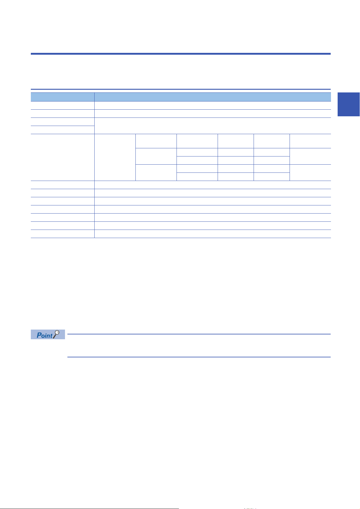
RELEVANT MANUALS
Manual name [manual number] Description Available form
CC-Link IE Field Network Basic Remote I/O Module
User's Manual
[SH-081763ENG] (this manual)
CC-Link IE Field Network Basic Reference Manual
[SH-081684ENG]
SLMP Reference Manual
[SH-080956ENG]
e-Manual refers to the Mitsubishi Electric FA electronic book manuals that can be browsed using a dedicated
tool.
e-Manual has the following features:
• Required information can be cross-searched in multiple manuals.
• Other manuals can be accessed from the links in the manual.
• The hardware specifications of each part can be found from the product figures.
• Pages that users often browse can be bookmarked.
• Sample programs can be copied to an engineering tool.
Part names, specifications, procedures before operation, system
configuration, installation, wiring, parameter settings, functions, programming,
and troubleshooting of the I/O module
Specifications, procedures before operation, system configuration,
programming, functions, parameter settings, and troubleshooting of CC-Link
IE Field Network Basic
The protocol (SLMP) used for data reading or writing from an external device
to the Ethernet-equipped module
Print book
e-Manual
PDF
Print book
e-Manual
PDF
Print book
e-Manual
PDF
9
Page 12

TERMS
Unless otherwise specified, this manual uses the following terms.
Term Description
Cyclic transmission A function by which data are periodically exchanged among stations on the same network using link
Disconnection A process of stopping data link if a data link error occurs
I/O combined module A generic term for CC-Link IE Field Network Basic remote I/O modules where a digital signal can be input
I/O module A generic term for CC-Link IE Field Network Basic remote I/O modules
Input module A generic term for CC-Link IE Field Network Basic remote I/O modules where a digital signal can be input
Label A label that represents a device in a given character string
Link device A device (RX, RY, RWr, RWw) in a CPU module that is used for communications with a slave station
Link scan (link scan time) After sending requests to all the slave stations and then receiving the responses from all the slave
Master station A station that controls the entire CC-Link IE Field Network Basic. Only one master station can be used in
Output module A generic term for CC-Link IE Field Network Basic remote I/O modules where a digital signal can be
Reference response time A time period taken from when a slave station on CC-Link IE Field Network Basic receives a request from
Remote input (RX) Bit data input from a slave station to the master station
Remote output (RY) Bit data output from the master station to a slave station
Remote register (RWr) Word data input from a slave station to the master station
Remote register (RWw) Word data output from the master station to a slave station
Reserved station A station reserved for future use. This station is not actually connected on CC-Link IE Field Network
Slave station A station that performs cyclic transmission with the master station on CC-Link IE Field Network Basic. The
SLMP The abbreviation for Seamless Message Protocol. This protocol is used to access an SLMP-compatible
Subnet mask A number used to logically divide one network into multiple subnetworks and manage them easily. The
devices on CC-Link IE Field Network Basic
and output
stations, the master station on CC-Link IE Field Network Basic starts sending another request to the slave
stations. The link scan time is a time period taken for the master station to start sending another request
after sending the previous requests.
a network.
output
the master station until it returns the response to the master station.
Basic, but counted as a connected station
station exchanges I/O signals (bit data)/I/O data (word data) with another station.
device or a programmable controller connected to an SLMP-compatible device from an external device.
following Ethernet network systems can be configured:
• A small-scale Ethernet network system in which multiple network devices are connected
• A medium- or large-scale network system in which multiple small-scale network systems are connected
via routers or other network communication devices
10
Page 13

1 PRODUCT LINEUP
1.1 Input Module
1
Module name Input specifications Module
power
supply
current
AC input module Screw terminal block
DC input module Positive common/
negative common
shared type
100 to 120VAC, 16 points
Screw terminal block
24VDC, 32 points
64mA 0.31kg NZ2MFB2-16A Page 16 NZ2MFB2-
71mA 0.30kg NZ2MFB1-32D Page 19 NZ2MFB1-
1.2 Output Module
Module name Output specifications Module
power
supply
current
Contact output module Screw terminal block
Transistor output
module
Sink type Screw terminal block
Source type Screw terminal block
240VAC/24VDC, 2A/point, 16
points
12 to 24VDC, 0.5A/point, 32
points
12 to 24VDC, 0.1A/point, 32
points
153mA 0.35kg NZ2MFB2-16R Page 22 NZ2MFB2-
85mA 0.30kg NZ2MFB1-32T Page 25 NZ2MFB1-
84mA 0.30kg NZ2MFB1-32TE1 Page 28 NZ2MFB1-
Weight Model Reference
16A AC input module
32D DC input module
Weight Model Reference
16R contact output module
32T transistor output
module
32TE1 transistor output
module
1.3 I/O Combined Module
Module name Input specifications, output
specifications
DC input/transistor
output module
Input part: Positive
common type
Output part: Sink
type
Input part: Negative
common type
Output part: Source
type
Screw terminal block
24VDC, 16 points
Screw terminal block
24VDC, 0.5A/point, 16 points
Screw terminal block
24VDC, 16 points
Screw terminal block
24VDC, 0.1A/point, 16 points
Module
power
supply
current
79mA 0.30kg NZ2MFB1-32DT Page 31 NZ2MFB1-
79mA 0.30kg NZ2MFB1-
Weight Model Reference
32DT DC input/transistor
output module
32DTE1
Page 35 NZ2MFB132DTE1 DC input/transistor
output module
1 PRODUCT LINEUP
1.1 Input Module
11
Page 14

MEMO
12
1 PRODUCT LINEUP
1.3 I/O Combined Module
Page 15

2 PART NAMES
(7)
(1) (2) (4)
(3) (5) (6)
(8)
(9)
This chapter describes part names of the I/O module.
No. Name Application
(1) Ethernet port Port connector for network connection. Connect an Ethernet cable.
100M LED Indicates the link status.
SD/RD LED Indicates the status of data communication.
(2) PW LED Indicates the power supply status of the I/O module.
RUN LED Indicates the operating status of the I/O module.
D LINK LED Indicates the data link status of the I/O module.
ERR. LED Indicates the error status of the I/O module.
(3) Function setting switch Used for the input response time setting function and output HOLD/CLEAR setting function.
(4) IP address setting switch Switch for setting the fourth octet of IP address
(5) X0 LED to XF LED Indicates the ON/OFF status of the inputs.
Y10 LED to Y1F LED Indicates the ON/OFF status of the outputs.
(6) I/O PW LED Indicates the status of the power supply from the external power supply.
(7) Terminal block for module
power supply and FG
(8) DIN rail hook A hook to mount an I/O module on a DIN rail
(9) I/O terminal block A terminal block for I/O power supply and I/O signals
*1 The status of actual input signals that are externally input is indicated on the LEDs regardless of the status of the remote input signal.
*2 Output commands from the I/O module are indicated on the LEDs regardless of the status of the external power supply.
2
For wiring method and precautions, refer to the following.
Page 61 Wiring of Ethernet cable
On: Linkup in progress
Off: Linkdown in progress
On: Data being sent or received
Off: Data not sent/received
On: Power supply ON
Off: Power supply OFF
On: Operating normally.
Off: A major error has occurred.
On: Data link in operation. (cyclic transmission in progress)
Flashing: Data link stop (cyclic transmission stopped)
Off: Data link not performed. (disconnected)
On: A moderate error or major error has occurred.
Flashing: A minor error has occurred.
Off: Operating normally.
For function details and setting method, refer to the following.
Page 65 Input Response Time Setting Function
Page 66 Output HOLD/CLEAR Setting Function
Page 51 IP address setting switch setting
*1
On: Input ON
Off: Input OFF
*2
On: Output ON
Off: Output OFF
On: External power supply ON
Off: External power supply OFF
A terminal block to connect the module power supply (24VDC) and FG.
2 PART NAMES
13
Page 16

MEMO
14
2 PART NAMES
Page 17
3 SPECIFICATIONS
This chapter describes the specifications of the I/O module.
3.1 General Specifications
Item Specifications
Operating ambient temperature 0 to 55
Storage ambient temperature -25 to 75
Operating ambient humidity 5 to 95%RH, non-condensing
Storage ambient humidity
Vibration resistance Compliant with JIS
Shock resistance Compliant with JIS B 3502 and IEC 61131-2 (147m/, 3 times each in X, Y, and Z directions)
Operating atmosphere No corrosive gases, flammable gases, less conductive dust
Operating altitude
Installation location Inside a control panel
Overvoltage category
Pollution degree
Equipment class Class
*1 Do not use or store the I/O module under pressure higher than the atmospheric pressure of altitude 0m. Doing so may cause
malfunction. When using the I/O module under pressure, please consult your local Mitsubishi representative.
*2 When the programmable controller is used at altitude above 2000m, the withstand voltage performance and the upper limit of the
operating ambient temperature decrease. Please consult your local Mitsubishi representative.
*3 If the environment satisfies the operating ambient temperature, operating ambient humidity and other conditions, the module can be
used even outside the control panel.
*4 This indicates the section of the power supply to which the equipment is assumed to be connected between the public electrical power
distribution network and the machinery within premises.
Category applies to equipment for which electrical power is supplied from fixed facilities. The surge voltage withstand level for up to
the rated voltage of 300V is 2500V.
*5 This index indicates the degree to which conductive material is generated in terms of the environment in which the equipment is used.
Pollution degree 2 is when only non-conductive pollution occurs. A temporary conductivity caused by condensing must be expected
occasionally.
*1
*4
*5
B 3502 and IEC
61131-2
0 to 2000m
or less
2 or less
*2
Frequency Constant
Under intermittent
vibration
Under continuous
vibration
*3
5 to 8.4Hz 3.5mm 10 times each in X,
8.4 to 150Hz 9.8m/
5 to 8.4Hz 1.75mm
8.4 to 150Hz 4.9m/
acceleration
Half amplitude Sweep count
Y, and Z directions
3
To ensure that this product complies with the EMC Directive, refer to the following.
Page 108 EMC and Low Voltage Directives
3.1 General Specifications
3 SPECIFICATIONS
15
Page 18

3.2 Performance Specifications
Input module
NZ2MFB2-16A AC input module
Item NZ2MFB2-16A
Station type Slave station
Number of input points 16 points
Rated input voltage/rated frequency 100 to 120VAC (+10%/-15%), 50/60Hz (3Hz)
Rated input current 8.2mA (100VAC, 60Hz), 6.8mA (100VAC, 50Hz)
Inrush current 200mA maximum within 1ms
Input voltage distortion ratio Within 5%
Max. number of simultaneous input points 100%
ON voltage/ON current 80VAC or more/5mA or more (50Hz, 60Hz)
OFF voltage/OFF current 30VAC or less/1.7mA or less (50Hz, 60Hz)
Input impedance Approx. 15k (60Hz), approx. 18k (50Hz)
Input response time OFFON 20ms or less (100VAC 60Hz)
ONOFF
Withstand voltage 1400VACrms for 1 minute between all AC external terminals and the ground
Insulation resistance 10M or higher between all AC external terminals and the ground, all DC external terminals and the
Noise immunity Noise voltage: 1500Vp-p (AC type), 500Vp-p (DC type), noise width 1s, noise frequency 25 to 60Hz
Protection degree IP1X
Wiring method for common 16 points/common (2-wire, screw terminal block type)
External interface Communication part RJ45 connector
Module power supply part Terminal block for module power supply and FG (Two-piece spring clamp terminal block (push-in
I/O part 34-point one-piece terminal block
Applicable DIN rail TH35-7.5Fe, TH35-7.5Al (compliant with IEC 60715)
Applicable wire size For power supply Stranded wire: 0.3 to 1.5 (22 to 16 AWG), terminal slot size: 2.8mm 2.0mm
For I/O Core: 0.3 to 2.0 (22 to 14 AWG)
Applicable solderless
terminal
Number of occupied stations One station
Reference response time 1ms
Communication cable An Ethernet cable that meets the 100BASE-TX standard
Module power supply Voltage 24VDC (ripple rate: 5% or less) (Allowable voltage range: 20.4 to 28.8VDC)
Weight 0.31kg
Terminal block for module
power supply and FG
Terminal block for input Page 62 Applicable solderless terminal
Current 64mA or less (24VDC, all points ON)
*1 Only one wire can be connected to a terminal of the terminal block for module power supply and FG. Multiple wires cannot be connected
to a terminal. Connecting two or more wires may cause a poor contact.
*2 It is recommended to use the bar solderless terminal for wiring.
510VACrms for 1 minute between all DC external terminals and the ground
ground (500VDC insulation resistance tester)
(noise simulator condition)
type))
Tightening torque range for terminal screw (M3 5.2 screw): 0.59 to 0.88Nm
Page 59 Applicable solderless terminal
*1
For details, refer to the following.
CC-Link IE Field Network Basic Reference Manual
*2
16
3 SPECIFICATIONS
3.2 Performance Specifications
Page 19
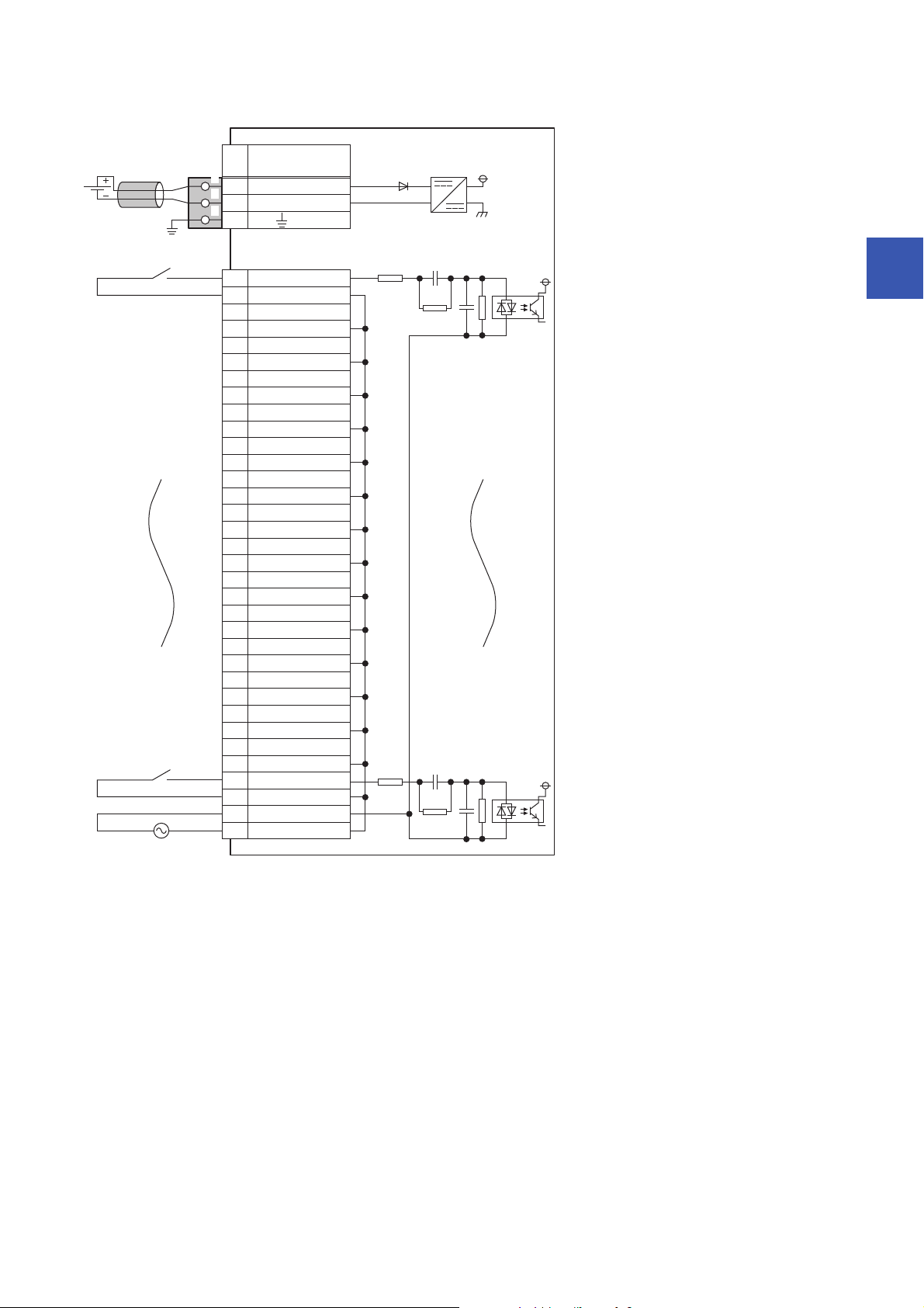
■External connection
FG
1
2
3
UNIT POWER
CABLE
1
2
3
X01
COM B2
X13
COM B4
X25
COM B6
7
COM B8
X49
COM B10
X511
COM B12
X613
COM B14
X715
COM B16
X817
COM B18
X919
COM B20
XA21
COM B22
XB23
COM B24
XC25
COM B26
XD27
COM B28
XE29
COM B30
XF31
COM B32
COM A33
COM B34
+24V
24G
X3
Signal name
Pin
No.
Non-insulated
Terminal block
for input
Terminal block for module
power supply and FG
*1
Module power
supply
AC100 to 120V
3
*1 Only one wire can be connected to a terminal of the terminal block for module power supply and FG. Multiple wires cannot be connected
to a terminal. Connecting two or more wires may cause a poor contact.
3 SPECIFICATIONS
3.2 Performance Specifications
17
Page 20

■Terminal block for input
13579111315171921232527293133
246810121416182022242628303234
Pin number Signal name Pin number Signal name
1X017X8
2 COM B 18 COM B
3X119X9
4 COM B 20 COM B
5X221XA
6 COM B 22 COM B
7X323XB
8 COM B 24 COM B
9X425XC
10 COM B 26 COM B
11 X5 2 7 X D
12 COM B 28 COM B
13 X6 29 XE
14 COM B 30 COM B
15 X7 31 XF
16 COM B 32 COM B
33 COM A
34 COM B
18
3 SPECIFICATIONS
3.2 Performance Specifications
Page 21

NZ2MFB1-32D DC input module
Item NZ2MFB1-32D
Station type Slave station
Number of input points 32 points
Rated input voltage 24VDC (ripple rate: 5% or less) (Allowable voltage range: 20.4 to 28.8VDC)
Rated input current 6.0mA TYP. (for 24VDC)
Isolation method Photocoupler isolation
Max. number of simultaneous input points 100%
ON voltage/ON current 15VDC or more/4mA or more
OFF voltage/OFF current 5VDC or less/1.7mA or less
Input resistance 3.8k
Input response time OFFON 0ms
ONOFF
Input type Positive common/negative common shared type
Withstand voltage 500VAC for 1 minute between all DC external terminals and the ground
Insulation resistance 10M or higher between all DC external terminals and ground (500VDC insulation resistance tester)
Noise immunity
Protection degree IP2X
Wiring method for common 32 points/common (two points) (1-wire, screw terminal block type)
External interface Communication part RJ45 connector
Applicable DIN rail TH35-7.5Fe, TH35-7.5Al (compliant with IEC 60715)
Applicable wire size For power supply Stranded wire: 0.3 to 1.5 (22 to 16 AWG), terminal slot size: 2.8mm 2.0mm
Applicable solderless
terminal
Number of occupied stations One station
Reference response time 1ms
Communication cable An Ethernet cable that meets the 100BASE-TX standard
Module power supply Voltage 24VDC (ripple rate: 5% or less) (Allowable voltage range: 20.4 to 28.8VDC)
Weight 0.30kg
*2
Module power supply part Terminal block for module power supply and FG (Two-piece spring clamp terminal block (push-in
I/O part 34-point one-piece terminal block
For I/O Core: 0.3 to 2.0 (22 to 14 AWG)
Terminal block for module
power supply and FG
Terminal block for input Page 62 Applicable solderless terminal
Current 71mA or less (24VDC, all points ON)
*3
*1 If the input response time is set to "0ms", the actual input response time is 80s at OFF ON, and 160s at ON OFF.
*2 It is the noise immunity of when the input response time setting value is other than "0ms". Note that the module is easily affected by
noise if "0ms" is set.
*3 Only one wire can be connected to a terminal of the terminal block for module power supply and FG. Multiple wires cannot be connected
to a terminal. Connecting two or more wires may cause a poor contact.
*4 It is recommended to use the bar solderless terminal for wiring.
*1
/0.2ms/1ms/1.5ms/5ms/10ms/20ms/70ms
(Initial setting: 10ms)
Noise voltage 500Vp-p, noise width 1s, noise frequency 25 to 60Hz (DC type noise simulator
condition)
type))
Tightening torque range for terminal screw (M3 5.2 screw): 0.59 to 0.88Nm
*4
Page 59 Applicable solderless terminal
For details, refer to the following.
CC-Link IE Field Network Basic Reference Manual
3
3 SPECIFICATIONS
3.2 Performance Specifications
19
Page 22
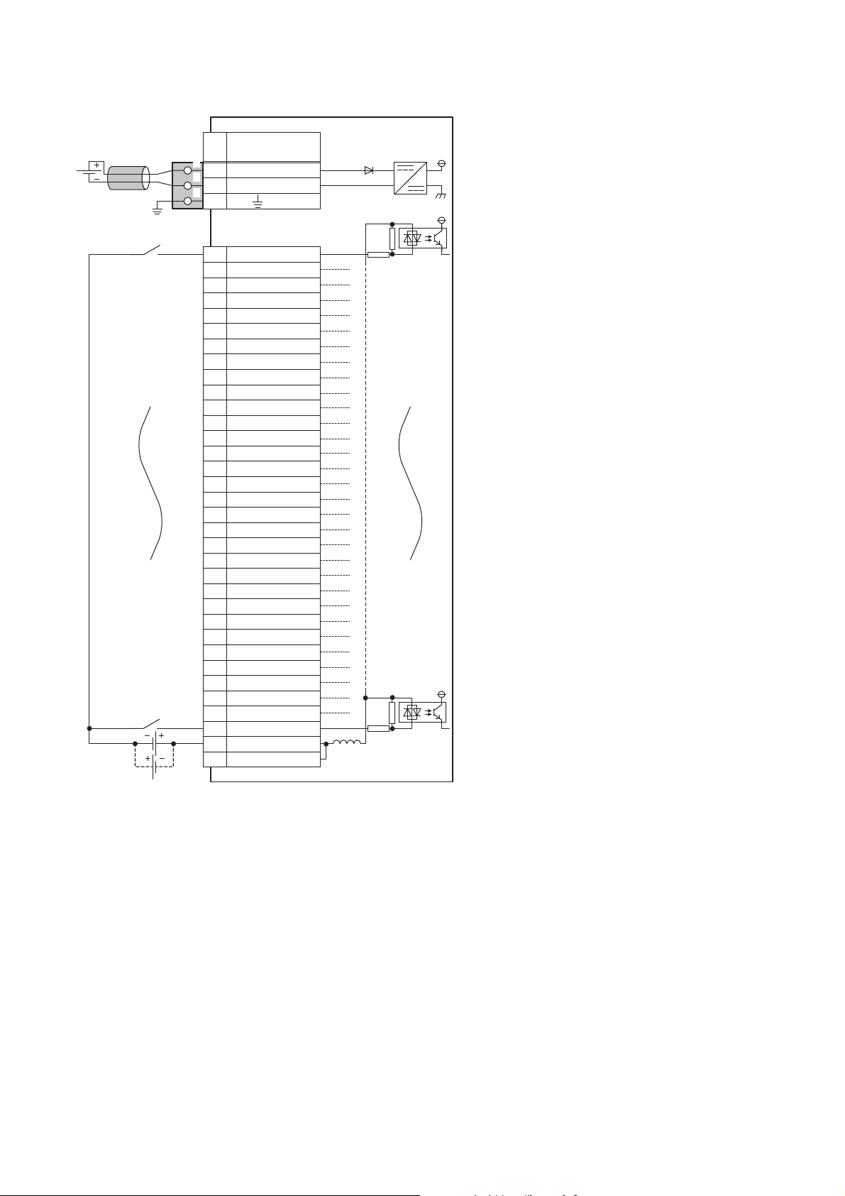
■External connection
FG
1
2
3
UNIT POWER
CABLE
1
2
3
X01
X12
X23
X34
X45
X56
7
X78
X89
X910
XA11
XB12
XC13
XD14
XE15
XF16
X1017
X1118
X1219
X1320
X1421
X1522
X1623
X1724
X1825
X1926
X1A27
X1B28
X1C29
X1D30
X1E31
X1F32
COM33
COM34
+24V
24G
X6
Signal name
Pin
No.
Non-insulated
Terminal block
for input
Terminal block for module
power supply and FG
*1
Module power
supply
*1 Only one wire can be connected to a terminal of the terminal block for module power supply and FG. Multiple wires cannot be connected
to a terminal. Connecting two or more wires may cause a poor contact.
3 SPECIFICATIONS
20
3.2 Performance Specifications
Page 23

■Terminal block for input
13579111315171921232527293133
246810121416182022242628303234
Pin number Signal name Pin number Signal name
1X017X10
2X118X11
3X219X12
4X320X13
5X421X14
6X522X15
7X623X16
8X724X17
9X825X18
10 X9 26 X19
11 XA 27 X1 A
12 XB 28 X1B
13 XC 29 X1C
14 XD 30 X1D
15 XE 31 X1E
16 XF 32 X1F
33 COM
34 COM
3
3 SPECIFICATIONS
3.2 Performance Specifications
21
Page 24

Output module
NZ2MFB2-16R contact output module
Item NZ2MFB2-16R
Station type Slave station
Number of output points 16 points
Rated switching voltage/current 24VDC 2A (resistance load)/point, 8A/common
Minimum switching load 5VDC 1mA
Maximum switching load 264VAC 125VDC
Output response time OFFON 10ms or less
ONOFF 12ms or less
Life Mechanical 20 million times or more
Electrical Rated switching voltage/current load 100 thousand times or more
Maximum switching frequency 3600 times/hour
Surge suppressor None
Fuse None
Withstand voltage 2300VACrms for 1 minute between all AC external terminals and the ground
Insulation resistance 10M or higher between all AC external terminals and the ground, all DC external terminals and the
Noise immunity Noise voltage: 1500Vp-p (AC type), 500Vp-p (DC type), noise width 1s, noise frequency 25 to 60Hz
Protection degree IP1X
Wiring method for common 16 points/common (2-wire, screw terminal block type)
External interface Communication part RJ45 connector
Module power supply part Terminal block for module power supply and FG (Two-piece spring clamp terminal block (push-in
I/O part 34-point one-piece terminal block
Applicable DIN rail TH35-7.5Fe, TH35-7.5Al (compliant with IEC 60715)
Applicable wire size For power supply Stranded wire: 0.3 to 1.5 (22 to 16 AWG), terminal slot size: 2.8mm 2.0mm
For I/O Core: 0.3 to 2.0 (22 to 14 AWG)
Applicable solderless
terminal
Number of occupied stations One station
Reference response time 1ms
Communication cable An Ethernet cable that meets the 100BASE-TX standard
Module power supply Voltage 24VDC (ripple rate: 5% or less) (Allowable voltage range: 20.4 to 28.8VDC)
Weight 0.35kg
Terminal block for module
power supply and FG
Terminal block for output Page 62 Applicable solderless terminal
Current 153mA or less (24VDC, all points ON)
*1 Only one wire can be connected to a terminal of the terminal block for module power supply and FG. Multiple wires cannot be connected
to a terminal. Connecting two or more wires may cause a poor contact.
*2 It is recommended to use the bar solderless terminal for wiring.
240VAC 2A (COS = 1)/point, 8A/common
Page 46 Relay life (contact switching life)
510VACrms for 1 minute between all DC external terminals and the ground
ground (500VDC insulation resistance tester)
(noise simulator condition)
type))
Tightening torque range for terminal screw (M3 5.2 screw): 0.59 to 0.88Nm
Page 59 Applicable solderless terminal
*1
For details, refer to the following.
CC-Link IE Field Network Basic Reference Manual
*2
22
3 SPECIFICATIONS
3.2 Performance Specifications
Page 25
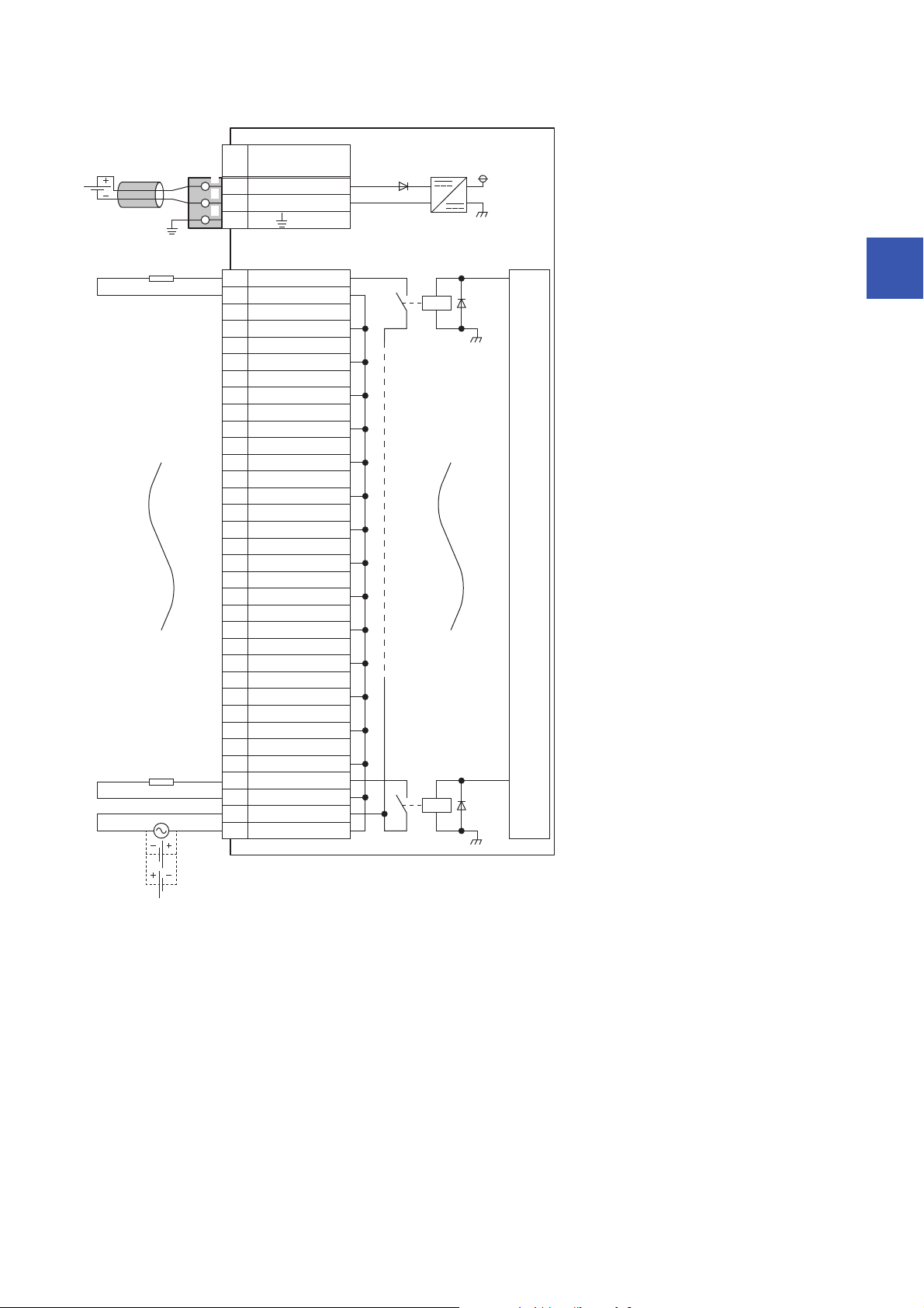
■External connection
FG
1
2
3
UNIT POWER
CABLE
1
2
3
Y01
COM B2
Y13
COM B4
Y25
COM B6
7
COM B8
Y49
COM B10
Y511
COM B12
Y613
COM B14
Y715
COM B16
Y817
COM B18
Y919
COM B20
YA21
COM B22
YB23
COM B24
YC25
COM B26
YD27
COM B28
YE29
COM B30
YF31
COM B32
COM A33
COM B34
+24V
24G
Y3
Signal name
Pin
No.
Non-insulated
Terminal block
for output
Terminal block for module
power supply and FG
*1
Module power
supply
Load
Load power
supply
Load
Internal circuit
100/200VAC
or 24VDC
3
*1 Only one wire can be connected to a terminal of the terminal block for module power supply and FG. Multiple wires cannot be connected
to a terminal. Connecting two or more wires may cause a poor contact.
3 SPECIFICATIONS
3.2 Performance Specifications
23
Page 26

■Terminal block for output
13579111315171921232527293133
246810121416182022242628303234
Pin number Signal name Pin number Signal name
1Y017Y8
2 COM B 18 COM B
3Y119Y9
4 COM B 20 COM B
5Y221YA
6 COM B 22 COM B
7Y323YB
8 COM B 24 COM B
9Y425YC
10 COM B 26 COM B
11 Y5 2 7 Y D
12 COM B 28 COM B
13 Y6 29 YE
14 COM B 30 COM B
15 Y7 31 YF
16 COM B 32 COM B
33 COM A
34 COM B
24
3 SPECIFICATIONS
3.2 Performance Specifications
Page 27

NZ2MFB1-32T transistor output module
Item NZ2MFB1-32T
Station type Slave station
Number of output points 32 points
Rated load voltage 12/24VDC (ripple rate: 5% or less) (Allowable voltage range: 10.2 to 28.8VDC)
Max. load current 0.5A/point, 5A/common
Isolation method Photocoupler isolation
Max. inrush current Current is limited by the overload protection function.
Leakage current at OFF 0.1mA or less
Max. voltage drop at ON 0.3VDC(TYP.)0.5A, 0.6VDC(MAX.)0.5A
Output response time OFFON 0.5ms or less
ONOFF 1.5ms or less (resistance load)
Surge suppressor Zener diode
External power supply for
output part
Output type Sink type
Withstand voltage 500VAC for 1 minute between all DC external terminals and the ground
Insulation resistance 10M or higher between all DC external terminals and ground (500VDC insulation resistance tester)
Noise immunity Noise voltage 500Vp-p, noise width 1s, noise frequency 25 to 60Hz (DC type noise simulator
Protection degree IP2X
Wiring method for common 32 points/common (two points) (1-wire, screw terminal block type)
Protection function Overload protection
External interface Communication part RJ45 connector
Applicable DIN rail TH35-7.5Fe, TH35-7.5Al (compliant with IEC 60715)
Applicable wire size For power supply Stranded wire: 0.3 to 1.5 (22 to 16 AWG), terminal slot size: 2.8mm 2.0mm
Applicable solderless
terminal
Number of occupied stations One station
Reference response time 1ms
Communication cable An Ethernet cable that meets the 100BASE-TX standard
Module power supply Voltage 24VDC (ripple rate: 5% or less) (Allowable voltage range: 20.4 to 28.8VDC)
Weight 0.30kg
*1 Only one wire can be connected to a terminal of the terminal block for module power supply and FG. Multiple wires cannot be connected
to a terminal. Connecting two or more wires may cause a poor contact.
*2 It is recommended to use the bar solderless terminal for wiring.
Voltage 12/24VDC (ripple rate: 5% or less) (Allowable voltage range: 10.2 to 28.8VDC)
Current 25mA or less (TYP. 24VDC per common) External load current is not included.
condition)
function
Overheat protection
function
Module power supply part Terminal block for module power supply and FG (Two-piece spring clamp terminal block (push-in
I/O part 34-point one-piece terminal block
For I/O Core: 0.3 to 2.0 (22 to 14 AWG)
Terminal block for module
power supply and FG
Terminal block for output Page 62 Applicable solderless terminal
Current 85mA or less (24VDC, all points ON)
Limited current when detecting overcurrent: 1A or more/point
Activated to each point.
Activated to each point.
type))
Tightening torque range for terminal screw (M3 5.2 screw): 0.59 to 0.88Nm
Page 59 Applicable solderless terminal
*1
For details, refer to the following.
CC-Link IE Field Network Basic Reference Manual
*2
3
3 SPECIFICATIONS
3.2 Performance Specifications
25
Page 28
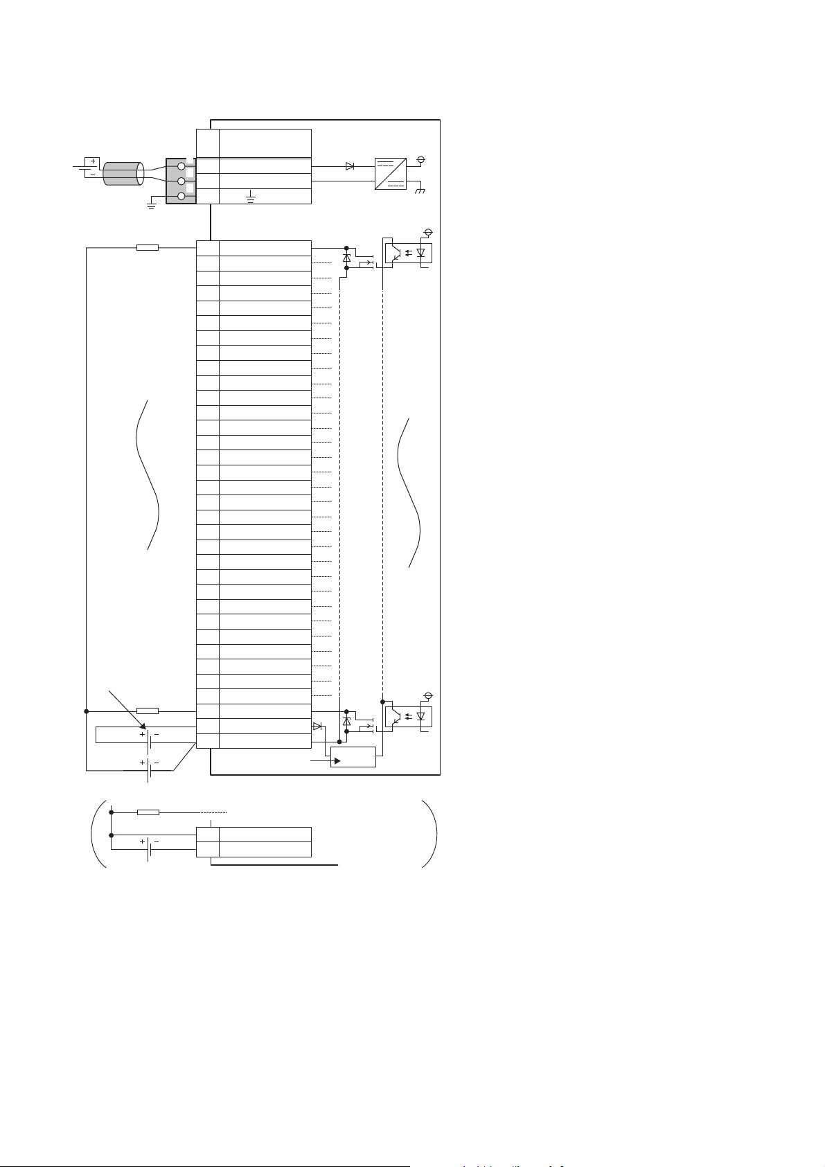
■External connection
FG
1
2
3
UNIT POWER
CABLE
1
2
3
+24V
24G
YF
Y0
Y1
Y2
Y3
Y4
Y5
Y6
Y7
Y8
Y9
YA
YB
YC
YD
YE
Y10
Y11
Y12
Y13
Y14
Y15
Y16
Y17
Y18
Y19
Y1A
Y1B
Y1C
Y1D
Y1E
Y1F
CTL+
COM-
1
2
3
4
5
6
7
8
9
10
11
12
13
14
15
16
17
18
19
20
21
22
23
24
25
26
27
28
29
30
31
32
33
34
33
34
CTL+
COM-
Signal name
Pin
No.
Non-insulated
Terminal block for module
power supply and FG
*1
Module power
supply
Terminal block
for output
Load
Load
Load
Load power
supply
External power supply for the output part
and load power supply (common)
External power supply
for the output part
Constant-voltage
circuit
*1 Only one wire can be connected to a terminal of the terminal block for module power supply and FG. Multiple wires cannot be connected
26
to a terminal. Connecting two or more wires may cause a poor contact.
3 SPECIFICATIONS
3.2 Performance Specifications
Page 29

■Terminal block for output
13579111315171921232527293133
246810121416182022242628303234
Pin number Signal name Pin number Signal name
1Y017Y10
2Y118Y11
3Y219Y12
4Y320Y13
5Y421Y14
6Y522Y15
7Y623Y16
8Y724Y17
9Y825Y18
10 Y9 26 Y19
11 YA 27 Y1 A
12 YB 28 Y1B
13 YC 29 Y1C
14 YD 30 Y1D
15 YE 31 Y1E
16 YF 32 Y1F
33 CTL+
34 COM-
3
3 SPECIFICATIONS
3.2 Performance Specifications
27
Page 30

NZ2MFB1-32TE1 transistor output module
Item NZ2MFB1-32TE1
Station type Slave station
Number of output points 32 points
Rated load voltage 12/24VDC (ripple rate: 5% or less) (Allowable voltage range: 10.2 to 28.8VDC)
Max. load current 0.1A/point, 2A/common
Isolation method Photocoupler isolation
Max. inrush current Current is limited by the overload protection function.
Leakage current at OFF 0.1mA or less
Max. voltage drop at ON 0.1VDC(TYP.)0.1A, 0.2VDC(MAX.)0.1A
Output response time OFFON 0.5ms or less
ONOFF 1.5ms or less (resistance load)
Surge suppressor Zener diode
External power supply for
output part
Output type Source type
Withstand voltage 500VAC for 1 minute between all DC external terminals and the ground
Insulation resistance 10M or higher between all DC external terminals and ground (500VDC insulation resistance tester)
Noise immunity Noise voltage 500Vp-p, noise width 1s, noise frequency 25 to 60Hz (DC type noise simulator
Protection degree IP2X
Wiring method for common 32 points/common (two points) (1-wire, screw terminal block type)
Protection function Overload protection
External interface Communication part RJ45 connector
Applicable DIN rail TH35-7.5Fe, TH35-7.5Al (compliant with IEC 60715)
Applicable wire size For power supply Stranded wire: 0.3 to 1.5 (22 to 16 AWG), terminal slot size: 2.8mm 2.0mm
Applicable solderless
terminal
Number of occupied stations One station
Reference response time 1ms
Communication cable An Ethernet cable that meets the 100BASE-TX standard
Module power supply Voltage 24VDC (ripple rate: 5% or less) (Allowable voltage range: 20.4 to 28.8VDC)
Weight 0.30kg
*1 Only one wire can be connected to a terminal of the terminal block for module power supply and FG. Multiple wires cannot be connected
to a terminal. Connecting two or more wires may cause a poor contact.
*2 It is recommended to use the bar solderless terminal for wiring.
Voltage 12/24VDC (ripple rate: 5% or less) (Allowable voltage range: 10.2 to 28.8VDC)
Current 25mA or less (TYP. 24VDC per common) External load current is not included.
condition)
function
Overheat protection
function
Module power supply part Terminal block for module power supply and FG (Two-piece spring clamp terminal block (push-in
I/O part 34-point one-piece terminal block
For I/O Core: 0.3 to 2.0 (22 to 14 AWG)
Terminal block for module
power supply and FG
Terminal block for output Page 62 Applicable solderless terminal
Current 84mA or less (24VDC, all points ON)
Limited current when detecting overcurrent: 1 to 3A/point
Activated to each point.
Activated to two points.
type))
Tightening torque range for terminal screw (M3 5.2 screw): 0.59 to 0.88Nm
Page 59 Applicable solderless terminal
*1
For details, refer to the following.
CC-Link IE Field Network Basic Reference Manual
*2
28
3 SPECIFICATIONS
3.2 Performance Specifications
Page 31

■External connection
UNIT POWER
CABLE
FG
1
2
3
1
2
3
+24V
24G
1
2
3
4
5
6
7
8
9
10
11
12
13
14
15
16
17
18
19
20
21
22
23
24
25
26
27
28
29
30
31
32
33
34
Y0
Y1
Y2
Y3
Y4
Y5
Y6
Y7
Y8
Y9
YF
YA
YB
YC
YD
YE
Y10
Y11
Y12
Y13
Y14
Y15
Y16
Y17
Y18
Y19
Y1A
Y1B
Y1C
Y1D
Y1E
Y1F
COM+
CTL-
Signal name
Pin
No.
Non-insulated
Terminal block for module
power supply and FG
*1
Module power
supply
Terminal block
for output
Load
Load
External power supply for
the output part and load
power supply (common)
Constant-voltage
circuit
3
*1 Only one wire can be connected to a terminal of the terminal block for module power supply and FG. Multiple wires cannot be connected
to a terminal. Connecting two or more wires may cause a poor contact.
3 SPECIFICATIONS
3.2 Performance Specifications
29
Page 32

■Terminal block for output
13579111315171921232527293133
246810121416182022242628303234
Pin number Signal name Pin number Signal name
1Y017Y10
2Y118Y11
3Y219Y12
4Y320Y13
5Y421Y14
6Y522Y15
7Y623Y16
8Y724Y17
9Y825Y18
10 Y9 26 Y19
11 YA 27 Y1 A
12 YB 28 Y1B
13 YC 29 Y1C
14 YD 30 Y1D
15 YE 31 Y1E
16 YF 32 Y1F
33 COM+
34 CTL-
30
3 SPECIFICATIONS
3.2 Performance Specifications
Page 33

I/O combined module
NZ2MFB1-32DT DC input/transistor output module
Item NZ2MFB1-32DT
Input specifications Output specifications
Station type Slave station
Number of input points 16 points
Rated input voltage 24VDC (ripple rate: 5% or less) (Allowable voltage
Rated input current 6.0mA TYP. (for 24VDC)
Isolation method Photocoupler isolation
Max. number of simultaneous input points 100%
ON voltage/ON current 15VDC or more/4mA or more
OFF voltage/OFF current 5VDC or less/1.7mA or less
Input resistance 3.8k
Input response time OFFON 0ms
ONOFF
Input type Positive common type
Number of output points 16 points
Rated load voltage 24VDC (ripple rate: 5% or less) (Allowable
Max. load current 0.5A/point, 4A/common
Isolation method Photocoupler isolation
Max. inrush current Current is limited by the overload protection
Leakage current at OFF 0.1mA or less
Max. voltage drop at ON 0.3VDC(TYP.)0.5A, 0.6VDC(MAX.)0.5A
Output response time OFFON 0.5ms or less
ONOFF 1.5ms or less (resistance load)
Surge suppressor Zener diode
External power supply for
output part
Output type Sink type
Protection function Overload protection
Wiring method for common 16 points/common (1-wire, screw terminal block
Withstand voltage 500VAC for 1 minute between all DC external terminals and the ground
Insulation resistance 10M or higher between all DC external terminals and ground (500VDC insulation resistance tester)
Noise immunity
Protection degree IP2X
External interface Communication part RJ45 connector
Applicable DIN rail TH35-7.5Fe, TH35-7.5Al (compliant with IEC 60715)
Applicable wire size For power supply Stranded wire: 0.3 to 1.5 (22 to 16 AWG), terminal slot size: 2.8mm 2.0mm
*2
Volt ag e 24VDC (ripple rate: 5% or less) (Allowable
Current 15mA or less (TYP. 24VDC per common)
function
Overheat protection
function
Module power supply part Terminal block for module power supply and FG (Two-piece spring clamp terminal block (push-in
I/O part 34-point one-piece terminal block
For I/O Core: 0.3 to 2.0 (22 to 14 AWG)
range: 20.4 to 28.8VDC)
*1
/0.2ms/1ms/1.5ms/5ms/10ms/20ms/70ms
(Initial setting: 10ms)
voltage range: 20.4 to 28.8VDC)
function.
voltage range: 20.4 to 28.8VDC)
External load current is not included.
Limited current when detecting overcurrent: 1A
or more/point
Activated to each point.
Activated to each point.
type)
Noise voltage 500Vp-p, noise width 1s, noise frequency 25 to 60Hz (DC type noise simulator
condition)
type))
Tightening torque range for terminal screw (M3 5.2 screw): 0.59 to 0.88Nm
16 points/common (1-wire, screw terminal
block type)
*4
3
3 SPECIFICATIONS
3.2 Performance Specifications
31
Page 34

Item NZ2MFB1-32DT
Input specifications Output specifications
Applicable solderless
terminal
Number of occupied stations One station
Reference response time 1ms
Communication cable An Ethernet cable that meets the 100BASE-TX standard
Module power supply Voltage 24VDC (ripple rate: 5% or less) (Allowable voltage range: 20.4 to 28.8VDC)
Weight 0.30kg
Terminal block for module
power supply and FG
I/O terminal block Page 62 Applicable solderless terminal
Current 79mA or less (24VDC, all points ON)
Page 59 Applicable solderless terminal
*3
For details, refer to the following.
CC-Link IE Field Network Basic Reference Manual
*1 If the input response time is set to "0ms", the actual input response time is 80s at OFF ON, and 160s at ON OFF.
*2 It is the noise immunity of when the input response time setting value is other than "0ms". Note that the module is easily affected by
noise if "0ms" is set.
*3 Only one wire can be connected to a terminal of the terminal block for module power supply and FG. Multiple wires cannot be connected
to a terminal. Connecting two or more wires may cause a poor contact.
*4 It is recommended to use the bar solderless terminal for wiring.
32
3 SPECIFICATIONS
3.2 Performance Specifications
Page 35

■External connection
FG
1
2
3
1
2
3
1
2
3
4
5
6
7
8
9
10
11
12
13
14
15
16
+24V
24G
17
18
19
20
21
22
23
24
25
26
27
28
29
30
31
32
33
34
33
34
COM+
COM-
X0
X1
X2
X3
X4
X5
X7
X8
X9
XA
XB
XC
XD
XE
XF
X6
Y1F
Y10
Y11
Y12
Y13
Y14
Y15
Y16
Y17
Y18
Y19
Y1A
Y1B
Y1C
Y1D
Y1E
COM+
COM-
Signal name
Pin
No.
Non-insulated
UNIT POWER
CABLE
Terminal block
for I/O
Connector for module
power supply and FG
*1
Module power
supply
Load
Load
Load
External power supply for the output part
and load power supply (common)
External power supply
for the output part
Load power
supply
Constant-voltage
circuit
3
*1 Only one wire can be connected to a terminal of the terminal block for module power supply and FG. Multiple wires cannot be connected
to a terminal. Connecting two or more wires may cause a poor contact.
3 SPECIFICATIONS
3.2 Performance Specifications
33
Page 36

■I/O terminal block
13579111315171921232527293133
246810121416182022242628303234
Pin number Signal name Pin number Signal name
1X017Y10
2X118Y11
3X219Y12
4X320Y13
5X421Y14
6X522Y15
7X623Y16
8X724Y17
9X825Y18
10 X9 26 Y19
11 XA 27 Y1 A
12 XB 28 Y1B
13 XC 29 Y1C
14 XD 30 Y1D
15 XE 31 Y1E
16 XF 32 Y1F
33 COM+
34 COM-
34
3 SPECIFICATIONS
3.2 Performance Specifications
Page 37

NZ2MFB1-32DTE1 DC input/transistor output module
Item NZ2MFB1-32DTE1
Input specifications Output specifications
Station type Slave station
Number of input points 16 points
Rated input voltage 24VDC (ripple rate: 5% or less) (Allowable voltage
Rated input current 6.0mA TYP. (for 24VDC)
Isolation method Photocoupler isolation
Max. number of simultaneous input points 100%
ON voltage/ON current 15VDC or more/4mA or more
OFF voltage/OFF current 5VDC or less/1.7mA or less
Input resistance 3.8k
Input response time OFFON 0ms
ONOFF
Input type Negative common type
Number of output points 16 points
Rated load voltage 24VDC (ripple rate: 5% or less) (Allowable
Max. load current 0.1A/point, 1.6A/common
Isolation method Photocoupler isolation
Max. inrush current Current is limited by the overload protection
Leakage current at OFF 0.1mA or less
Max. voltage drop at ON 0.1VDC(TYP.)0.1A, 0.2VDC(MAX.)0.1A
Output response time OFFON 0.5ms or less
ONOFF 1.5ms or less (resistance load)
Surge suppressor Zener diode
External power supply for
output part
Output type Source type
Protection function Overload protection
Wiring method for common 16 points/common (1-wire, screw terminal block
Withstand voltage 500VAC for 1 minute between all DC external terminals and the ground
Insulation resistance 10M or higher between all DC external terminals and ground (500VDC insulation resistance tester)
Noise immunity
Protection degree IP2X
External interface Communication part RJ45 connector
Applicable DIN rail TH35-7.5Fe, TH35-7.5Al (compliant with IEC 60715)
Applicable wire size For power supply Stranded wire: 0.3 to 1.5 (22 to 16 AWG), terminal slot size: 2.8mm 2.0mm
Applicable solderless
terminal
*2
Volt ag e 24VDC (ripple rate: 5% or less) (Allowable
Current 20mA or less (TYP. 24VDC per common)
function
Overheat protection
function
Module power supply part Terminal block for module power supply and FG (Two-piece spring clamp terminal block (push-in
I/O part 34-point one-piece terminal block
For I/O Core: 0.3 to 2.0 (22 to 14 AWG)
Terminal block for module
power supply and FG
I/O terminal block Page 62 Applicable solderless terminal
range: 20.4 to 28.8VDC)
*1
/0.2ms/1ms/1.5ms/5ms/10ms/20ms/70ms
(Initial setting: 10ms)
voltage range: 20.4 to 28.8VDC)
function.
voltage range: 20.4 to 28.8VDC)
External load current is not included.
Limited current when detecting overcurrent: 1
to 3A/point
Activated to each point.
Activated to two points.
16 points/common (1-wire, screw terminal
type)
Noise voltage 500Vp-p, noise width 1s, noise frequency 25 to 60Hz (DC type noise simulator
condition)
type))
Tightening torque range for terminal screw (M3 5.2 screw): 0.59 to 0.88Nm
Page 59 Applicable solderless terminal
*3
block type)
*4
3
3 SPECIFICATIONS
3.2 Performance Specifications
35
Page 38

Item NZ2MFB1-32DTE1
Input specifications Output specifications
Number of occupied stations One station
Reference response time 1ms
Communication cable An Ethernet cable that meets the 100BASE-TX standard
Module power supply Voltage 24VDC (ripple rate: 5% or less) (Allowable voltage range: 20.4 to 28.8VDC)
Current 79mA or less (24VDC, all points ON)
Weight 0.30kg
*1 If the input response time is set to "0ms", the actual input response time is 80s at OFF ON, and 160s at ON OFF.
*2 It is the noise immunity of when the input response time setting value is other than "0ms". Note that the module is easily affected by
noise if "0ms" is set.
*3 Only one wire can be connected to a terminal of the terminal block for module power supply and FG. Multiple wires cannot be connected
to a terminal. Connecting two or more wires may cause a poor contact.
*4 It is recommended to use the bar solderless terminal for wiring.
For details, refer to the following.
CC-Link IE Field Network Basic Reference Manual
36
3 SPECIFICATIONS
3.2 Performance Specifications
Page 39

■External connection
FG
1
2
3
1
2
3
1
2
3
4
5
6
7
8
9
10
11
12
13
14
15
16
+24V
24G
17
18
19
20
21
22
23
24
25
26
27
28
29
30
31
32
33
34
X0
X1
X2
X3
X4
X5
X7
X8
X9
XA
XB
XC
XD
XE
XF
X6
Y1F
Y10
Y11
Y12
Y13
Y14
Y15
Y16
Y17
Y18
Y19
Y1A
Y1B
Y1C
Y1D
Y1E
COM+
COM-
Signal name
Pin
No.
Non-insulated
UNIT POWER
CABLE
Terminal block
for I/O
Connector for module
power supply and FG
*1
Module power
supply
Load
Load
External power supply for
the output part and load
power supply (common)
Constant-voltage
circuit
3
*1 Only one wire can be connected to a terminal of the terminal block for module power supply and FG. Multiple wires cannot be connected
to a terminal. Connecting two or more wires may cause a poor contact.
3 SPECIFICATIONS
3.2 Performance Specifications
37
Page 40

■I/O terminal block
13579111315171921232527293133
246810121416182022242628303234
Pin number Signal name Pin number Signal name
1X017Y10
2X118Y11
3X219Y12
4X320Y13
5X421Y14
6X522Y15
7X623Y16
8X724Y17
9X825Y18
10 X9 26 Y19
11 XA 27 Y1 A
12 XB 28 Y1B
13 XC 29 Y1C
14 XD 30 Y1D
15 XE 31 Y1E
16 XF 32 Y1F
33 COM+
34 COM-
38
3 SPECIFICATIONS
3.2 Performance Specifications
Page 41

3.3 Function List
This section lists the functions of I/O modules.
Item Description Reference
Input function The ON/OFF status (X signal) of inputs is notified to Remote input (RX) of the master
station.
Output function The ON/OFF status (Y signal) of outputs is controlled with Remote output (RY) of the
master station.
Input response time setting function This function prevents an incorrect input due to noise by setting the response time
until the module recognizes an actual input as the X signal.
Output HOLD/CLEAR setting function When the I/O module is disconnected from data link, or the CPU module operating
status is STOP, whether to hold or clear the last output value can be set by this
function.
Protection function The overload protection function and overheat protection function protect the internal
circuit from overcurrent and its heat.
SLMP communication function SLMP can be used to communicate with the I/O module. Page 68 SLMP
Page 65 Input Response
Time Setting Function
Page 66 Output HOLD/
CLEAR Setting Function
Page 67 Protection
Function
communication function
3.4 List of Functions of Each Module
This section lists the functions of each module.
: Available, : Not available
Model name Input function Output function Input response
time setting
function
NZ2MFB2-16A
NZ2MFB1-32D
NZ2MFB2-16R
NZ2MFB1-32T
NZ2MFB1-32TE1
NZ2MFB1-32DT
NZ2MFB1-32DTE1
Output HOLD/
CLEAR setting
function
Protection
function
SLMP
communication
function
3
3 SPECIFICATIONS
3.3 Function List
39
Page 42

4 PROCEDURES BEFORE OPERATION
This chapter describes the procedures before operation.
1. IP address setting switch setting
Set the fourth octet of IP address of I/O module.
Page 51 IP address setting switch setting
2. Function setting switch setting
Set the input response time setting and output HOLD/CLEAR setting of the I/O module.
Page 54 Function setting switch setting
3. Connection
Mount the I/O module on the DIN rail.
Page 57 Mounting the module on a DIN rail
4. Wiring
Wire the power supply, Ethernet cables, and external devices to the I/O module.
Page 59 Wiring
5. Parameter setting and programming
Set the network parameter of the master station and create a program.
Page 63 Network Configuration Setting
Page 69 PROGRAMMING
To replace the module, follow the procedure described below:
• Turn off the module power supply and remove the I/O module.
• Prepare a new I/O module and perform the procedure before operation, from "IP address setting switch
setting" to "Parameter setting and programming". At this time, the settings of IP address setting switch and
function setting switch must be the same as the settings for I/O module before replacement.
• Check that the D LINK LED and RUN LED of I/O module are on and ERR. LED is off before restarting
control operation.
40
4 PROCEDURES BEFORE OPERATION
Page 43

MEMO
4
4 PROCEDURES BEFORE OPERATION
41
Page 44

5 SYSTEM CONFIGURATION
Applicable master station
For the CPU module that can be used as the master station of CC-Link IE Field Network Basic, refer to the following.
CC-Link IE Field Network Basic Reference Manual
Compatible software version
For the compatible software version, always keep GX Works3/GX Works2 up to date.
When the latest software version is necessary, please consult your local Mitsubishi representative.
Applicable profile
A profile is required to use the I/O module in the network configuration setting of CC-Link IE Field Network Basic.
When the latest profile of the I/O module is necessary, please consult your local Mitsubishi representative.
The profile is a setting file that stores information required for the start-up, operation, and maintenance of devices supporting
the CC-Link family.
A module is added to the "Module List" of the network configuration setting window by profile registration to GX Works3/GX
Works2.
For the profile registration, refer to the following.
Operating manual for the tool to be used
Ethernet cable
For the specifications of the Ethernet cable, refer to the following.
CC-Link IE Field Network Basic Reference Manual
Hub
For compatible hubs, refer to the following.
CC-Link IE Field Network Basic Reference Manual
42
5 SYSTEM CONFIGURATION
Page 45

MEMO
5
5 SYSTEM CONFIGURATION
43
Page 46

6 INSTALLATION AND WIRING
IN
COM
Inductive
load
IN
COM
Inductive
load
This chapter describes the installation and wiring of the I/O module.
6.1 Before Using the I/O Modules
Input modules
Precautions common to all input modules
■Number of simultaneous ON points
The number of input points that can be turned on at the same time varies depending on the input voltage and ambient
temperature. Refer to the maximum number of simultaneous input points of the specifications of each input module. (
Page 16 Performance Specifications)
Precautions when using the DC input module
■Measures against back EMF
When connecting an inductive load, connect a diode in parallel with the load. Use the diode that satisfies the following
conditions:
• A reverse breakdown voltage is ten or more times as high as the circuit voltage.
• A forward current is two or more times as high as the load current.
Positive common Negative common
44
6 INSTALLATION AND WIRING
6.1 Before Using the I/O Modules
Page 47

Output module
Output
module
Resistor
Load
Output
module
Inductor Load
Precautions common to all output modules
■Maximum switching frequency when load is driven
The maximum switching frequency imposes a limit on the use; an ON state or an OFF state must not be changed without an
interval of at least one second.
■Load to be connected
When connecting a counter or timer utilizing a DC/DC converter as a load of the output module, select an output module
whose maximum load current is higher than the inrush current of a load to be connected. If the selection is based on the
average current of a load to be connected, an inrush current flows cyclically from the load while the output module is in an ON
state or in operation, which can cause failure of the module. If it is necessary to select a module on the basis of the average
current of a load to be connected, to alleviate the effect of the inrush current, take any of the following corrective actions:
• Connecting a resistor in series with the load
• Connecting an inductor in series with the load
6
6 INSTALLATION AND WIRING
6.1 Before Using the I/O Modules
45
Page 48

Precautions when using the contact output module
200
Y
100
70
50
30
20
10
7
5
3
2
1
0.1 0.2 0.3 0.5 0.7 1 2 3 5
X
AC100V cos
Φ=0.7
DC30V τ=0ms
AC200V cos
Φ=0.7
AC200V cos
Φ=0.35
DC24V τ=7ms
AC120V cos
Φ=0.2
AC240V cos
Φ=0.2
DC100V
τ=7ms
AC100V cos
Φ=0.35
When using the contact output module, carefully consider the following points:
• Relay life (contact switching life)
• Influence on the relay life by a connected load
• Measures against back EMF
■Relay life (contact switching life)
Applicable module: NZ2MFB2-16R
The relay life varies depending on the environment where a module is used. When using a module, take the use environment
into consideration.
The relay life curve below shows the actual service values, not the guaranteed values. Since an actual contact switching life
may be shorter than the relay life curve, replace the module with a sufficient margin for the life.
X: Switching current (A)
Y: Switching life (in units of 10000 times)
(L/R): Time constant
cos: Power factor
Use environment Contact switching life
Rated switching voltage/current load 100 thousand times
1.5A at 200VAC, 1A at 240VAC (COS = 0.7) 100 thousand times
0.4A at 200VAC, 0.3A at 240VAC (COS = 0.7) 300 thousand times
1A at 200VAC, 0.5A at 240VAC (COS = 0.35) 100 thousand times
0.3A at 200VAC, 0.15A at 240VAC (COS = 0.35) 300 thousand times
1A at 24VDC, 0.1A at 100VDC (L/R = 7ms) 100 thousand times
0.3A at 24VDC, 0.03A at 100VDC (L/R = 7ms) 300 thousand times
6 INSTALLATION AND WIRING
46
6.1 Before Using the I/O Modules
Page 49

Influence on the relay life by a connected load
i
io
t
i
io
t
io
i
t
i
io
t
An actual relay life can be substantially shorter than the relay life curve depending on the type of a connected load and the
characteristics of its inrush current. ( Page 46 Relay life (contact switching life))
The inrush current generated by a connected load can lead to contact welding of the module. To prevent shortening of the
relay life and contact welding, take the following measures:
• Considering the possibility of a high inrush current, select a load so that the inrush current generated by the connected load
falls within the range of the rated current of the module.
• Connect a relay capable of withstanding the inrush current, outside the module.
The following table lists the relations between typical loads and each inrush current.
Select a load so that the inrush current, i, and rated current, io, fall within the range of the rated switching current described in
the module specifications. In some loads, the inrush current flows for a long time.
Load type Waveform Inrush current
i/rated current
io
Inductive load Load of a solenoid
i: Inrush current
io: Rated current
t: 0.07 to 0.1 seconds
Lamp load Load of an incandescent lamp
Approx. 10 to 20
times
Approx. 3 to 10
times
Waveform Inrush current
i/rated current
io
Load of an electromagnetic contactor
i: Inrush current
io: Rated current
t: 0.017 to 0.033 seconds (1 to 2 cycle)
Load of a mercury lamp
Approx. 3 to 10
times
Approx. 3 times
*1
6
i: Inrush current
io: Rated current
t: Approx. 0.33 seconds
Load of a fluorescent lamp
i
t
i: Inrush current
io: Rated current
t: within 10 seconds
io
Approx. 5 to 10
times
i: Inrush current
io: Rated current
t: 180 to 300 seconds (3 to 5 minutes)
6 INSTALLATION AND WIRING
6.1 Before Using the I/O Modules
47
Page 50

Load type Waveform Inrush current
*1
Inductive
load
Inductive
load
Inductive
load
i/rated current
io
Capacitive load Capacitive load
*2
Approx. 20 to 40
times
Waveform Inrush current
i/rated current
io
i
t
i: Inrush current
io: Rated current
t: 0.008 to 0.33 seconds (0.5 to 2 cycle)
io
*1 A typical discharge lamp circuit is configured with a combination of discharge tubes, transformers, choke coils, capacitors and others.
Because of this, be especially careful of the case of a high power factor and a low power supply impedance, where the inrush current
flowing into the output module can be 20 to 40 times as high as the rated current.
*2 When the wiring is long, be careful with the cable capacity as well.
■Measures against back EMF
Provide a contact protection circuit for an extended contact life, noise prevention at contact close, and reduction of the
carbides and nitric acids formed by an arc discharge.
An incorrect circuit involves a high risk of contact welding.
With the contact protection circuit, the recovery time may be delayed.
The following table shows typical examples of the contact protection circuit.
Circuit example Element selection criteria Remarks
Capacitor +
resistance method
(CR method)
Inductive
load
Estimate the constants of a capacitor and
resistance with the following as a guide.
Some differences, however, may arise from
a variation in the nature and characteristics
of the load.
• Capacitor: 0.5 to 1 (F) for a load current
of 1A
• Resistance: 0.5 to 1 () for a power
supply voltage of 1V
Use a capacitor whose withstand voltage is
equal to or higher than the rated voltage. In
an AC circuit, use a capacitor with no
polarity.
When a relay or solenoid is used as the
load, the recovery time is delayed.
A capacitor has the effect of reducing a
discharge at contact OFF, while a
resistance has the effect of limiting a
current at contact ON.
Diode method Use a diode that satisfies the following
Diode + zener diode
method
Inductive
load
Varistor method Select a varistor whose cut-off voltage (Vc)
conditions:
• A reverse breakdown voltage is ten or
more times as high as the circuit voltage.
• A forward current is two or more times as
high as the load current.
Use a zener diode whose zener voltage is
equivalent to or higher than the power
supply voltage.
satisfies the following condition:
• Vc > Power supply voltage 1.5 (V)
• Vc > Power supply voltage 1.5 (V) 2
(on AC power supply)
Note that selecting an element of an
excessively high Vc leads to a weaker
effect.
6 INSTALLATION AND WIRING
48
6.1 Before Using the I/O Modules
The recovery time is delayed than the CR
method.
This method is suitable for the case where
the diode method results in a substantial
delay in the recovery time.
The recovery time is a little delayed.
Page 51

*1 On AC power supply, the impedance of the CR needs to be sufficiently higher than that of the load. (for preventing errors due to the
Inductive
load
Inductive
load
leakage current of the CR).
• Avoid using contact protection circuits like the following. Although they are highly effective in reducing the
arc at current cutoff, a charge current flows into the capacitor when the contact turns on or off, which leads
to the risk of contact welding. A DC inductive load, generally considered to be more difficult to open and
close than a resistive load, can achieve the same performance of a resistive load in an appropriate
configuration of the protection circuit.
• Install the protection circuit near the load or contact (module). A long distance between them may inhibit the
effect of the protection circuit. As a guide, install it at a distance of no more than 50cm.
6
6 INSTALLATION AND WIRING
6.1 Before Using the I/O Modules
49
Page 52

Precautions when using the transistor output module
OUT1
OUT2
COM
OUT1
OUT2
COM
Load
Load
OUT
COM
Additional circuit
■Measures against reverse current
In the following connections, a reverse current flows to the output element, which can cause failure.
When wiring, set up diodes as the following figures show:
• When connecting transistor output modules in parallel
Sink type Source type
OUT1
OUT2
COM
OUT1
OUT2
COM
Load
Load
• When providing another circuit in parallel with a transistor output module
Sink type Source type
Additional circuit
OUT
COM
■Measures against back EMF
When connecting an inductive load, connect a diode in parallel with the load.
Use the diode that satisfies the following conditions:
• A reverse breakdown voltage is ten or more times as high as the circuit voltage.
• A forward current is two or more times as high as the load current.
Sink type Source type
OUT
COM
Inductive
load
OUT
COM
Inductive
load
■About element protection of the output module
If excessive noise affects the terminals of the output module, the output may be turned on to help the protection of the output
element. Adjust the voltage between terminals of the output module to fall within the operating load voltage range by taking
measures such as the following:
• To use an inductive load such as a relay, a surge suppressor is required on the load side as well. Take appropriate
measures with the measures against back EMF as a guide.
• To prevent excessive noise, avoid installing power cables together with I/O cables.
50
6 INSTALLATION AND WIRING
6.1 Before Using the I/O Modules
Page 53

6.2 Setting Switch
Ex.
200 0+ + 0 + + + + + + + = 235020100 4 0 1
IP address setting switch setting
Set the fourth octet of IP address using the IP address setting switch on the front of I/O module.
The setting of IP address setting switch is enabled when the I/O module is powered on. Thus, set this function when the
module is powered off.
Setting procedure
• Set the hundreds place digit to 200 or 100 of IP address setting switch.
• Set the tens place digit to 80, 40, 20, or 10 of IP address setting switch.
• Set the ones place digit to 8, 4, 2, or 1 of IP address setting switch.
To set to 235:
6
Setting range
The setting value must be in the range between 1 and 254.
If the value equal to or more than 255 is set, the following events occur.
• A moderate error occurs and ERR. LED turns on.
• The IP address of I/O module will be 192.168.3.100.
• Do not change the IP address setting switch while the module is powered on. Changing the IP address
setting switch while the module is powered on causes a minor error and flashes the ERR. LED. Returning
the IP address setting switch to the previous setting eliminates the error and turns off the ERR. LED.
• Do not set an IP address with duplicated fourth octet in the access range of CC-Link IE Field Network Basic.
Duplicated fourth octet causes the duplicated IP address due to the automatic setting of the first to third
octet, resulting in failure of data link establishment. ( Page 101 Setting IP Addresses and Subnet
Masks)
6 INSTALLATION AND WIRING
6.2 Setting Switch
51
Page 54

Automatic setting of the first to third octet of IP address
(1) 192.168.1.10
(2) 192.168.1
(3) 10
Master station
Slave station
(1) 192.168.1.10
(2) 192.168.1
(3) 10
(1) 192.168.2.7
(2) 192.168.2
(3) 7
Master station 1
Master station 2
Slave station 1
Slave station 2
The first to third octet of IP address is automatically set by the I/O module according to the settings of the master station. (The
factory default setting is 192.168.3.)
■When there is one master station:
Receives the information of network configuration setting from the master station.
Searches for the IP address with fourth octet matching the IP address setting switch from the network configuration setting
information.
If any address with matched fourth octet is found, the first to third octet is set to the own station based on the matched network
configuration setting information.
(1) IP address of I/O module
(2) The first to third octet of network configuration setting
(3) The setting value of IP address setting switch
■When there are multiple master stations:
Receives the information of network configuration setting from the master station 1 and 2.
Searches for the IP address with fourth octet matching the IP address setting switch from the network configuration setting
information of the master station 1 and 2.
If any address with matched fourth octet is found, the first to third octet is set to the own station based on the matched network
configuration setting information.
52
(1) IP address of I/O module
(2) The first to third octet of network configuration setting
(3) The setting value of IP address setting switch
6 INSTALLATION AND WIRING
6.2 Setting Switch
Page 55

• Automatic setting of the first to third octet of IP address is executed only once during the initial
communication with the master station after the I/O module is powered on. When the IP address of the I/O
module in the network parameter at the master station is changed while the data link between the I/O
module and master station is established, power off and on the I/O module as well after the parameter of
master station is reflected.
• The subnet mask for automatic setting of the first to third octet of IP address is 255.255.255.0 (fixed). If the
subnet mask needs to be set to the value other than 255.255.255.0, set the IP address and subnet mask
manually. ( Page 101 Setting IP Addresses and Subnet Masks)
• If the module is powered on while the IP address setting switch is 0, IP address is not set automatically.
Operation starts with the IP address and subnet mask set from GX Works3/GX Works2. ( Page 101
Setting IP Addresses and Subnet Masks)
6
6 INSTALLATION AND WIRING
6.2 Setting Switch
53
Page 56

Function setting switch setting
Set the input response time setting and output HOLD/CLEAR setting using the function setting switch on the front of I/O
module.
No. Switch name Function to be used Setting details
1 Function setting switch 1 to 3 Input response time setting
2
3
4 Function setting switch 4 Output HOLD/CLEAR setting
function
function
Do not change the function setting switch while the module is powered on. Changing the function setting
switch while the module is powered on causes a minor error and flashes the ERR. LED. Returning the
function setting switch to the previous setting eliminates the error and turns off the ERR. LED.
Set the input response time.
For setting method, refer to the following.
Page 65 Setting method
Set output HOLD/CLEAR.
For setting method, refer to the following.
Page 66 Setting method
54
6 INSTALLATION AND WIRING
6.2 Setting Switch
Page 57

6.3 Installation Environment and Installation Position
(1) (1)(1)
(1) (1)
(1) (1)
Installation environment
Installation location
Do not install the I/O module to the place where:
• Ambient temperature is outside the range of 0 to 55;
• Ambient humidity is outside the range of 10 to 90% RH;
• Condensation occurs due to rapid temperature change;
• Corrosive gas or combustible gas is present;
• Conductive powder such as dust and iron powder, oil mist, salinity, or organic solvent is filled;
• The I/O module is exposed to direct sunlight;
• A strong electric field or strong magnetic field is generated; and
• The I/O module is subject to vibration and shock.
Installation surface
Install the I/O module on the flat surface. When the installation surface is uneven, excessive force is applied to the printed-
circuit board and may cause a defect.
Installation position
When installing the I/O module in a control panel, provide clearance of 60mm or longer (1) between the module and the sides
of control panel or neighboring modules to ensure good ventilation and an easy module change.
6
6 INSTALLATION AND WIRING
6.3 Installation Environment and Installation Position
55
Page 58

Installation direction
(1)
The I/O module can be installed in six directions.
Use the DIN rail (1) to install the module.
56
6 INSTALLATION AND WIRING
6.3 Installation Environment and Installation Position
Page 59

6.4 Installation
Mounting the module on a DIN rail
An example of the use of the DIN rail stopper is described in the following procedure. Fix the module
according to the manual of the DIN rail stopper used.
Mounting procedure
1. Pull down all DIN rail hooks on the back of the module.
The hooks should be pulled down until they click.
2. Hang the upper tabs of the module on a DIN rail, and
push the module in position.
3. Lock the DIN rail hooks to the DIN rail to secure the
module in position.
Push each hook up until it clicks. If the hooks are beyond the
reach, use a tool such as a driver.
4. Loosen the screw on DIN rail stopper.
5. Hitch the bottom hook of the DIN rail stopper to the
bottom of the DIN rail.
Hitch the hook according to the orientation of the arrow on
the front of the stopper.
6
6. Hitch the upper hook of the DIN rail stopper to the top of
the DIN rail.
6 INSTALLATION AND WIRING
6.4 Installation
57
Page 60

7. Slide the DIN rail stopper up to the left side of the
module.
8. Hold the DIN rail stopper in the direction opposite to the
arrow on the stopper and tighten the screw with a driver.
9. Install the DIN rail stopper on the right side of the
module in the same procedure.
Install the stopper upside down for the right side.
Do not slide the module from the edge of the DIN rail when mounting it. The module may be damaged.
Removal procedure
Remove the module from the DIN rail by reversing the above procedure.
Applicable DIN rail model (compliant with IEC 60715)
• TH35-7.5Fe
• TH35-7.5Al
Interval between DIN rail mounting screws
Tighten the screws at intervals of 200mm or less.
DIN rail stopper
Use a stopper that is attachable to the DIN rail.
58
6 INSTALLATION AND WIRING
6.4 Installation
Page 61

6.5 Wiring
Wiring with terminal block for module power supply and FG
Wiring with spring clamp terminal block
■Tightening torque
Tighten the terminal block mounting screw within the following specified torque range.
Tightening the screw too much may damage the module case.
Screw type Tightening torque range
Terminal block mounting screw (M2.5 screw) 0.2 to 0.3Nm
■Wire to be used
The following table describes the wire to be connected to the terminal block for module power supply and FG.
Diameter Typ e Material Temperature rating
22 to 16 AWG Stranded Copper 75 or more
■Applicable solderless terminal
The following table lists the applicable solderless terminal.
Product name Model name Applicable wire size Bar solderless terminal
tool
Bar solderless
terminal
TE 0.5-8, TE 0.5-10 0.3 to 0.5 NH-79 NICHIFU Co., Ltd.
TE 0.75-8, TE 0.75-10 0.75
TE 1.0-8, TE 1.0-10 1.0
TE 1.5-8, TE 1.5-10 1.5
AI 0.34-8TQ 0.34 CRIMPFOX6 PHOENIX CONTACT GmbH & Co. KG
AI 0.5-8WH, AI 0.5-10WH 0.5
AI 0.75-8GY, AI 0.75-10GY 0.75
AI 1-8RD, AI 1-10RD 1.0
AI 1.5-8BK, AI 1.5-10BK 1.5
Contact
■Installing and removing the terminal block
To remove the terminal block, loosen the terminal block mounting screw with a flathead screwdriver.
To install the terminal block, tighten the terminal block mounting screw with a flathead screwdriver.
Failure to secure the terminal block may cause drop, short circuit, or malfunction.
6
6 INSTALLATION AND WIRING
6.5 Wiring
59
Page 62

■Connecting and disconnecting the cable
(1)
2.0mm
2.8mm
Insertion slot
To connect the cable, fully insert a wire having a bar solderless terminal into a wire insertion opening.
After inserting the wire, pull it lightly to check that it is securely clamped.
Continuity can be checked with test terminal (1).
To disconnect the cable, push in the open/close button with a Phillips screwdriver or flathead screwdriver.
With the button pushed in, pull out the wire having a bar solderless terminal.
■Precautions
• Use a bar solderless terminal for the wiring to the push-in type spring clamp terminal block. If a stripped wire is inserted into
a wire insertion opening, the wire cannot be securely clamped.
• For how long the wire should be stripped, follow the specifications of the bar solderless terminal used. To attach a bar
solderless terminal to a wire, use a crimping tool.
• Before inserting a bar solderless terminal into a wire insertion opening, check the shape of the opening and the shape of
the terminal. Insert the terminal paying attention to the orientation. If a bar solderless terminal larger than the wire insertion
opening is inserted, the terminal block may be damaged.
60
6 INSTALLATION AND WIRING
6.5 Wiring
Page 63

Wiring of Ethernet cable
Wiring method
■Installation method
1. Power off the power supplies of the I/O module and the external device.
2. Push the Ethernet cable connector into the I/O module until it clicks. Pay attention to the connector's direction.
3. Power on the module power supply of the I/O module.
4. Power on the external device.
5. Check if the 100M LED on the port into which the Ethernet cable is connected is on.
*1 The time taken for the 100M LED to turn on after connection of the Ethernet cable may vary. The 100M LED normally turns on in a few
second. However, if link-up processing is repeated due to a condition of a device on the line, the longer time may be required. If the
100M LED does not turn on, refer to the following and take a corrective action.
Page 78 When the 100M LED turns off
■How to disconnect
1. Power off the module power supply of the I/O module.
2. Press down the latch of the Ethernet cable and unplug the cable.
Precautions
For precautions when wiring the Ethernet cable, refer to the following.
CC-Link IE Field Network Basic Reference Manual
* 1
6
6 INSTALLATION AND WIRING
6.5 Wiring
61
Page 64

Wiring of external device and I/O terminal block
(1)
Wiring of screw terminal block
■Tightening torque
Tighten the terminal screw within the following specified torque range.
Tightening the screw too much may damage the module case.
Screw type Tightening torque range
Terminal screw (M3 5.2 screw) 0.59 to 0.88Nm
■Wire to be used
The following table describes the wire to be connected to the screw terminal block.
Diameter Typ e Material Temperature rating
22 to 14 AWG Stranded Copper 75 or more
■Applicable solderless terminal
The following table lists the applicable solderless terminal.
Model name Applicable wire size Contact
RAV1.25-3 0.3 to 1.25
V2-MS3 1.25 to 2.0 JST Mfg. Co., Ltd.
RAP2-3SL 1.25 to 2.0 Nippon Tanshi Co., Ltd.
TGV2-3N 1.25 to 2.0 NICHIFU Co., Ltd.
■Signal name and wiring
For the signal names of the terminal block and wiring of the external device, refer to the specifications of each module.
Incorrect wiring can cause malfunction of or damage on the module.
Page 16 Performance Specifications
■Wiring method
1. Loosen the terminal screw. Connect the round
solderless terminal (1) as it is.
• Do not put oil on the terminal and screw. Failure to do so may damage the screw.
• The number of the applicable solderless terminals must be two or less. When inserting two applicable
solderless terminals, insert them back-to-back. Otherwise the screw cannot be tightened and it may
damage the screw.
• Tighten the terminal screw with an applicable driver. Tightening with an inapplicable driver may damage the
screw.
62
6 INSTALLATION AND WIRING
6.5 Wiring
Page 65

7 PARAMETER SETTING
7.1 Network Configuration Setting
Write the network configuration setting into the master station before starting the operation of I/O module.
For how to set the network configuration of the master station, refer to the following.
CC-Link IE Field Network Basic Reference Manual
Setting procedure
1. Display the network configuration setting window.
For how to display the network configuration setting window, refer to the following.
CC-Link IE Field Network Basic Reference Manual
2. Select the I/O module to be connected from the "Module List", and then drag and drop it.
7
3. After the I/O module appears, enter the IP address and subnet mask.
The setting items of I/O module Setting details
IP Address First to third octet Same value as the first to third octet of the IP address of master station
Fourth octet Same as the value of IP address setting switch of I/O module
Subnet Mask 255.255.255.0
*1 The subnet mask for automatic setting of the first to third octet of IP address is 255.255.255.0 (fixed). If the subnet mask needs to be set
to the value other than 255.255.255.0, set the IP address and subnet mask manually. ( Page 101 Setting IP Addresses and Subnet
Masks)
*1
7 PARAMETER SETTING
7.1 Network Configuration Setting
63
Page 66

4. Close the network configuration setting window.
[Network Configuration Settings] [Close with Reflecting the Setting]
5. Write the set parameter to the CPU module of the master station and reset the CPU module, or turn off and on the power
supply.
[Online] [Write to PLC]
Setting item
For details on items for network configuration setting, refer to the following.
CC-Link IE Field Network Basic Reference Manual
64
7 PARAMETER SETTING
7.1 Network Configuration Setting
Page 67

8 FUNCTIONS
This chapter describes the details of the functions available in the I/O module, and the setting method for those functions.
8.1 Input Response Time Setting Function
This function prevents an incorrect input due to noise by setting the response time until the module recognizes an actual input
as the X signal.
Setting method
1. Set the input response time using the function setting switch 1 to 3 of I/O module.
Function setting switch 1 to 3 Input response time setting
1 2 3
OFFOFFOFF10ms (default)
OFF OFF ON 0ms
OFF ON OFF 0.2ms
OFF ON ON 1ms
ON OFF OFF 1.5ms
ON OFF ON 5ms
ON ON OFF 20ms
ON ON ON 70ms
The setting status of input response time can be checked by bit0 to bit2 of detailed module information (upper).
For details, refer to the following.
Page 105 Detailed module information (upper)
8
Precautions
Noise may be taken in as an input depending on the input response time setting.
The pulse width which is taken in as an input varies depending on the input response time.
To set the input response time, consider fully the operating environment.
The following table shows the minimum values of the pulse widths which may be taken in as an input. The pulse widths lower
than the values shown below can be filtered as noise.
Value of input response time setting 0ms 0.2ms 1.0ms 1.5ms 5ms 10ms 20ms 70ms
The minimum value of the pulse width which may be
taken in as an input (the maximum pulse widths which
can be filtered as noise)
0.004ms 0.15ms 0.4ms 2ms 4ms 9ms 36ms
8 FUNCTIONS
8.1 Input Response Time Setting Function
65
Page 68

8.2 Output HOLD/CLEAR Setting Function
When the I/O module is disconnected from data link, or the CPU module operating status is STOP, whether to hold or clear
the last output value can be set by this function.
Output HOLD/CLEAR setting and its operation
When HOLD or CLEAR is set for an output, the output is turned on or off as follows.
Operating status Output HOLD/CLEAR setting
HOLD
Last output status
OFF
Data link in operation CPU module in RUN OFF ON OFF ON
CPU module in STOP OFF ON OFF OFF
CPU module in PAUSE OFF ON OFF ON
CPU module in RESET OFF ON OFF OFF
CPU module suspended by
error
During disconnection/cyclic stop OFF ON OFF OFF
OFF ON OFF OFF
Last output status ONLast output status
If a moderate or major error has occurred in the I/O module, output turns off regardless of the output HOLD/CLEAR setting.
Setting method
1. Set HOLD or CLEAR using the function setting switch 4 of I/O module.
Output HOLD/CLEAR setting
CLEAR
Last output status
OFF
ON
Function setting switch 4 Output HOLD/CLEAR setting
4
OFF CLEAR (default)
ON HOLD
The setting status of output HOLD/CLEAR setting can be checked by bit3 of detailed module information (upper).
For details, refer to the following.
Page 105 Detailed module information (upper)
66
8 FUNCTIONS
8.2 Output HOLD/CLEAR Setting Function
Page 69

8.3 Protection Function
The overload protection function and overheat protection function protect the internal circuit from overcurrent and its heat.
Overload protection function
If the transistor output module and I/O combined module (transistor output part) detect overcurrent, the module performs the
current limiting operation (that imposes a limit on the output current to a constant value and keeps the output).
For the overcurrent detection value and the limited current, refer to the overload protection function in the specifications for
each module.
Page 22 Output module
Page 31 I/O combined module
If the load current becomes equal to the overcurrent detection value or lower, the module returns to normal operation.
Overheat protection function
If the transistor output module and I/O combined module (transistor output part) keep outputting the overcurrent caused by an
overload, heat is generated inside the module. If the module detects a high heat in its inside, it turns off the output.
The multiple points at which the overheat protection function operates depend on the module. Refer to the overheat protection
function in the specifications for each module.
Page 22 Output module
Page 31 I/O combined module
If the heat descends, the module automatically returns to normal operation.
The overload protection function and the overheat protection function do not protect external devices but
protect the internal circuit of the module.
A problem on a load may raise the internal temperature of the module, causing deterioration in output
elements and discoloration on the case and the printed-circuit board. Turn off the corresponding output as
soon as a problem on a load is found, and remove the cause.
8
8 FUNCTIONS
8.3 Protection Function
67
Page 70

8.4 SLMP communication function
SLMP can be used to communicate with the I/O module.
For details on SLMP, refer to the following.
SLMP Reference Manual
Available command
Item Command Subcommand Description
Typ e Operation
Remote Control Remote Reset 1006 0000 Executes the remote RESET for I/O module.
Communication setting
If I/O module and SLMP are used for communication, use the following settings.
• Communication method: UDP/IP
• Port number: 61550
• Code: Binary code
How to use
If SLMP command needs to be sent from the CPU module to I/O module, use the SP.SLMPSND instruction.
For the SP.SLMPSND instruction, refer to the manual for respective series.
MELSEC iQ-R Programming Manual (Instructions, Standard Functions/Function Blocks)
MELSEC iQ-F FX5 Programming Manual (Instructions, Standard Functions/Function Blocks)
QnUCPU User's Manual (Communication via Built-in Ethernet Port)
MELSEC-L CPU Module User's Manual (Built-In Ethernet Function)
When the I/O module detects an SLMP command error, abnormal response is returned whereas error status
does not occur in the I/O module. Since an error code is stored in the end code of the abnormal response
data, refer to the following table to check the error contents and take actions.
Page 68 End code of SLMP communications
End code of SLMP communications
The codes that are stored in the end codes when the I/O module returns the abnormal response are as follows:
End code Error name Description and cause Action
C059H Command error A command or subcommand is
incorrectly specified.
C05CH Request message error Request message is incorrect. Correct the content and send it again.
C061H Request data length error Request data length does not match
the number of data.
CEE1H Request message size error The size of request message has
exceeded the upper limit.
Correct the command or subcommand and send it
again.
Correct the content or length of request data and send it
again.
Correct the content and send it again.
68
8 FUNCTIONS
8.4 SLMP communication function
Page 71

9 PROGRAMMING
This chapter describes the programming of the I/O module.
9.1 Precautions for Programming
Cyclic transmission program
To create a cyclic transmission program, configure an interlock so that the process is executed while the cyclic transmission is
normally performed between the master station and slave station. For the interlock program of cyclic transmission, refer to the
following.
CC-Link IE Field Network Basic Reference Manual
9
9 PROGRAMMING
9.1 Precautions for Programming
69
Page 72

9.2 Program Example
(1)
(2)
(3) (4)
System configuration
(1) Master station
• Power supply module: R62P
• CPU module: R04CPU
(2) Slave station (station number: 1, IP address setting switch: 1)
• I/O combined module: NZ2MFB1-32DT
(3) X0 input signal (pressing button)
(4) Y10 output signal (lamp)
The setting procedure assumes the use of GX Works3.
70
9 PROGRAMMING
9.2 Program Example
Page 73

■Assignment of link devices
X
(2)(1)
X1000
·
X100F
X1010
·
X103F
Y
Y1000
·
Y100F
W
W100
·
W11F
W
W200
·
W21F
Y1010
·
Y101F
Y1020
·
Y103F
RX
RX0
·
RX0F
RX10
·
RX3F
RY
RY0
·
RY0F
RWr
RWr0
·
RWr1F
RWw
RWw0
·
RWw1F
RY10
·
RY1F
RY20
·
RY3F
RX
RX0
·
RX0F
RX10
·
RX3F
RY
RY0
·
RY0F
RWr
RWr0
·
RWr1F
RWw
RWw0
·
RWw1F
RY10
·
RY1F
RY20
·
(3)
(4)
(4)
(4)
(4)
(5)
(4)
RY3F
9
(1) Master station: CPU module
(2) Slave station (station number 1): I/O combined module
(3) Input signal
(4) Use prohibited
(5) Output signal
9 PROGRAMMING
9.2 Program Example
71
Page 74

Label to be used
■Module label
Use the following module labels.
Module label Description Device
RCPU.stSM.bSts_CyclicTransmission Cyclic transmission status SM1536
RCPU.stSD.bnSts_CyclicTransmission_Station[1] Cyclic transmission status of each station (station
number 1)
SD1536.0
■Label to be defined
Define the global labels as follows.
Setting procedure
1. Create a project with the contents below.
[Project] [New...]
2. Set whether or not to use CC-Link IE Field Network Basic.
[Navigation window] [Parameter] [CPU module model name] [Module Parameter] [Basic Settings]
3. Display the network configuration setting window and configure the setting as follows.
[Navigation window] [Parameter] [CPU module model name] [Module Parameter] [Basic Settings] [Network
Configuration Settings]
4. Close the network configuration setting window.
[Network Configuration Settings] [Close with Reflecting the Setting]
72
9 PROGRAMMING
9.2 Program Example
Page 75

5. Display the refresh setting window and configure the setting as follows.
[Navigation window] [Parameter] [CPU module model name] [Module Parameter] [Basic Settings] [Refresh
Settings]
6. After the parameter setting, click the [Apply] button.
7. Write the set parameter to the CPU module of the master station and reset the CPU module, or turn off and on the power
supply.
[Online] [Write to PLC]
9
9 PROGRAMMING
9.2 Program Example
73
Page 76

Program example
74
9 PROGRAMMING
9.2 Program Example
Page 77

10 MAINTENANCE AND INSPECTION
The I/O module has no special item to be inspected. However, to maintain the best condition of the system, perform the
inspection in accordance with the items described in the user's manual of the CPU module used.
10
10 MAINTENANCE AND INSPECTION
75
Page 78

MEMO
76
10 MAINTENANCE AND INSPECTION
Page 79

11 TROUBLESHOOTING
This chapter describes error contents that may occur while the I/O module is used and those troubleshooting.
11.1 Checking the LEDs
This section describes how to troubleshoot the system by the LEDs.
Determine the status of module error
Error status can be determined by the On/Off status of RUN LED and ERR. LED as follows.
RUN LED ERR. LED Error type
Off On
On On Moderate error Indicates that the module has stopped control operation due to setting error.
On Flashing Minor error Indicates that the module has been operating despite the detection of communication
*1 When multiple errors occur, the error status is displayed in the order of major error > moderate error > minor error.
*2 When the module is failed, the LED may not turn on.
*2
Major error Indicates that the module has stopped operation due to hardware failure.
When the PW LED does not turn on
Check item Action
Is any LED other than the PW LED turned on? When any LED other than the PW LED turns on, the possible cause is a hardware
Is the module power supply (24VDC) wired? Wire the module power supply (24VDC).
Is the module power supply (24VDC) turned on? Turn on the module power supply (24VDC).
Is the voltage of the module power supply (24VDC) within the specified
range?
*1
Description
failure or change of switch.
failure. Please consult your local Mitsubishi representative.
Set the voltage value within the range of performance specifications.
11
When the I/O PW LED does not turn on
Check item Action
Is the external power supply (24VDC) wired? Wire the external power supply (24VDC).
Is the external power supply (24VDC) turned on? Turn on the external power supply (24VDC).
Is the voltage of the external power supply (24VDC) within the specified
range?
Set the voltage value within the range of performance specifications.
When the RUN LED does not turn on
Check item Action
Does the voltage of the module power supplied externally reach to the
voltage of the specifications?
Has any hardware failure occurred?
Check that module power supply voltage is within the range of performance
specifications. ( Page 16 Performance Specifications)
After the check, power off and on the module power supply.
If the RUN LED does not turn on even after the module power supply is powered off
and on, the possible cause is a module failure. Please consult your local Mitsubishi
representative.
When the D LINK LED turns off
Check item Action
Has any error occurred? Determine the error factor by the CC-Link IE Field Network Basic diagnostic window
Is the station-to-station distance 100m or less? Change the station-to-station distance to 100m or less.
Does the cabling condition (bending radius) meet the specifications? Refer to the manual for the Ethernet cable used, and correct the bending radius.
Does the switching hub normally operate? • Check that a 100BASE-TX-compliant switching hub is used.
Is the IP address of the I/O module duplicated with any of other
devices?
or LED status of I/O module, and take action.
• Check that the power supply of the switching hub is turned on.
IP address of the I/O module must not be duplicated with another device.
11 TROUBLESHOOTING
11.1 Checking the LEDs
77
Page 80

When the D LINK LED flashes
Check item Action
Does the IP address setting of I/O module match the IP address of I/O
module specified in the configuration setting of master station?
Is the I/O module set to a reserved station? Set the reserved station specification of I/O module to have no setting in the network
Is the number of occupied stations set to other than 1? Set the number of occupied stations of I/O module to 1 in the network configuration
Is the IP address of the I/O module duplicated with any of other
devices?
The IP address of I/O module must match the IP address specified in the
configuration setting of master station.
configuration setting, and reflect the changed parameter in the CPU module.
setting, and reflect the changed parameter in the CPU module.
IP address of the I/O module must not be duplicated with another device.
When the 100M LED turns off
Check item Action
Are Ethernet cables normal? • Check that 100BASE-TX-compliant Ethernet cables are used.
Do the switching hub and other stations in the system normally
operate?
• Check that the station-to-station distance is 100m or less.
• Check that the Ethernet cables are not disconnected.
• Check that a 100BASE-TX-compliant switching hub is used.
• Check that the power supplies of the switching hub and other stations are turned
on.
When the SD/RD LED remains turned off
Check item Action
Are Ethernet cables normal? • Check that 100BASE-TX-compliant Ethernet cables are used.
• Check that the station-to-station distance is 100m or less.
• Check that the Ethernet cables are not disconnected.
Do the switching hub and other stations in the system normally
operate?
• Check that a 100BASE-TX-compliant switching hub is used.
• Check that the power supplies of the switching hub and other stations are turned
on.
When the ERR. LED turns on
Check item Action
Has any moderate or major error occurred? Determine the error factor by the CC-Link IE Field Network Basic diagnostic window
or LED status of I/O module, and take action.
When the ERR. LED flashes
Check item Action
Has any minor error occurred? Determine the error factor by the error code of diagnostic information 2 of slave
station, and take action.
Page 103 Diagnostic information list
78
11 TROUBLESHOOTING
11.1 Checking the LEDs
Page 81

11.2 CC-Link IE Field Network Basic Diagnostics
Check the network status or error definition of I/O module to perform troubleshooting by executing the CC-Link IE Field
Network Basic diagnostics.
How to use
For how to use the CC-Link IE Field Network Basic diagnostics, refer to the following.
CC-Link IE Field Network Basic Reference Manual
11
11 TROUBLESHOOTING
11.2 CC-Link IE Field Network Basic Diagnostics
79
Page 82

11.3 Troubleshooting by Symptom
Perform troubleshooting by symptom when the I/O module does not operate properly with no error.
Check the following items in the order from the top.
When the ON/OFF status of an external input cannot be read
Check item Action
Is the corresponding LED (X0 LED to X1F LED) of the input module and I/O
combined module on when an external input device is on?
Is the setting of the refresh device correct? Check the refresh parameter and correct the setting of the refresh device so that
Is data link established?
(Check the data link status on the CC-Link IE Field Network Basic
diagnostic window.)
When the ON/OFF status of an external output cannot be changed
If the LED does not turn on, there is a problem on the input wiring.
Check the wiring confirming that the input wiring is not disconnected or shortcircuited, or the voltage of the input signal is correct.
For the rated input voltage, check the rated input voltage column of each I/O
module specifications.
Page 16 Input module
Page 31 I/O combined module
Refer to the following as well.
Page 81 Troubleshooting for input circuit
it matches with the setting in the program. For the setting of the refresh
parameters, refer to the following.
CC-Link IE Field Network Basic Reference Manual
Determine the error factor by the CC-Link IE Field Network Basic diagnostic
window or LED status of I/O module, and take action.
Check item Action
Is the I/O PW LED turned on? Take corrective action according to the following.
Is the corresponding LED (Y0 LED to Y1F LED) of the output module and I/
O combined module on when an external output signal RY0 to RY1F is
turned on?
Is the setting of the refresh device correct? Check the refresh parameter and correct the setting of the refresh device so that
Is data link established?
(Check the data link status on the CC-Link IE Field Network Basic
diagnostic window.)
Page 77 When the I/O PW LED does not turn on
If the LED turns on, there is a problem on the output wiring.
Check the wiring confirming that the output wiring is not disconnected or shortcircuited.
Refer to the following as well.
Page 86 Troubleshooting for output circuit
it matches with the setting in the program. For the setting of the refresh
parameters, refer to the following.
CC-Link IE Field Network Basic Reference Manual
Determine the error factor by the CC-Link IE Field Network Basic diagnostic
window or LED status of I/O module, and take action.
When "Communication Setting Reflection of Slave Station" does not work
Check item Action
Is the IP address setting switch of I/O module set to 0? Set the IP address setting switch of I/O module to 0 and execute
"Communication Setting Reflection of Slave Station" again.
Is the MAC address for the selected I/O module correct? Check that the MAC address for the selected I/O module matches with the MAC
address for the target I/O module, and execute "Communication Setting
Reflection of Slave Station" again.
80
11 TROUBLESHOOTING
11.3 Troubleshooting by Symptom
Page 83

11.4 Examples of Troubles with the I/O Module
C
Power supply
AC input
Input module
Leakage
current
R
C
AC input
Input module
Power supply
Power supply
AC input
Input module
Leakage
current
Troubleshooting for input circuit
An input signal does not turn off No.1
■Cause
There is a leakage current from the input switch (driven by a contactless switch and others).
■Action
Connect an appropriate resistor so that the voltage between terminals of the input module would fall below the OFF voltage.
11
The recommended CR constant is as follows: 0.1 to 0.47F + 47 to 120 (1/2W).
An input signal does not turn off No.2
■Cause
There is a leakage current from the input switch (driven by a limit switch with neon lamp).
■Action
Take either of the following actions:
• Connect an appropriate resistor so that the voltage between terminals of the input module would fall below the OFF
voltage. (Same as the action taken when an input signal does not turn off No.1)
• Make the circuit independent and provide another display circuit.
11 TROUBLESHOOTING
11.4 Examples of Troubles with the I/O Module
81
Page 84

An input signal does not turn off No.3
C
Power supply
AC input
Input module
Leakage
current
Power supply
AC input
Input module
DC input (sink)
Input module
Leakage current
DC input (sink)
Input module
Resistor
■Cause
There is a leakage current due to the line capacity of the wiring cables. (The line capacity, C, of a twisted pair cable is as
follows: C = approx. 100pF/m.)
■Action
Connect an appropriate resistor so that the voltage between terminals of the input module would fall below the OFF voltage.
(Same as the action taken when an input signal does not turn off No.1)
A leakage current is not generated, however, where the power supply lies in the input device side like the figure below:
An input signal does not turn off No.4
■Cause
Even though the switch with LED indicator is turned off, leakage current exceeding the OFF current flowing through the input
module has occurred.
■Action
Connect an appropriate resistor so that the current flowing through the input module falls below the OFF current.
For the calculation example of a resistor to be connected, refer to the following.
Page 83 Calculation example
82
11 TROUBLESHOOTING
11.4 Examples of Troubles with the I/O Module
Page 85

■Calculation example
Input module
Leakage current 3mA
24VDC
Z = 3.8kΩ
I
R = 1.3mA
3mA
Iz = 1.7mA
24VDC
Resistor
R ≤
I
R
IZ
1.3
1.7
× Z = × 3.8 = 4.97[kΩ]
W = V2R = 26.4
2
÷
3900 = 0.179[W]
÷
× 3[mA] = 5.77[V]
3.9[kΩ]
1
3.8[kΩ]
1
+
1
If the switch with LED indicator with maximum leakage current of 3mA when 24VDC is supplied to the NZ2MFB1-32D is
connected
1. The OFF current of NZ2MFB1-32D is not 1.7mA or lower. Therefore, connect a resistor as shown below.
Z: Input impedance
2. To satisfy the condition that the OFF current of NZ2MFB1-32D is 1.7mA or lower, the current through the connected
resistor should be 1.3mA or higher. From the formula below, the connected resistor (R) is lower than 4.97k.
3. When the resistor (R) is 3.9k, for example, the power capacity (W) of the resistor (R) becomes 0.179W.
V: Input voltage
4. Because the resistor requires the power capacity of 3 to 5 times as large as the actual current consumption, the resistor
connected to the terminal should be 3.9k; and 1 to 2W.
5. OFF voltage when the resistor (R) is connected becomes 5.77V. This satisfies that the OFF voltage of NZ2MFB1-32D is
8V or lower.
11
11 TROUBLESHOOTING
11.4 Examples of Troubles with the I/O Module
83
Page 86

An input signal does not turn off No.5
E1 E2
E1 > E2
DC input
Input module
E1 E2
DC input
Input module
■Cause
By using two power supplies, a sneak path is configured.
■Action
• Use one power supply.
• To prevent the sneak path, connect a diode as shown below.
84
11 TROUBLESHOOTING
11.4 Examples of Troubles with the I/O Module
Page 87

An input signal does not turn on (AC input module).
Ex.
(1)
■Cause
Around the zero cross voltage (1) of the input signal (AC), there are step-like deformations as shown below:
■Action
Improve the input signal waveform by using an on-line type UPS and others.
A signal incorrectly inputs data
■Cause
Noise is taken as input data.
■Action
Set a longer input response time.
Page 65 Input Response Time Setting Function
1ms5ms
If the issue still continues, take the following two actions.
• To prevent excessive noise, avoid installing power cables together with I/O cables.
• Connect surge absorbers to noise-generating devices such as relays and conductors using the same power supply or take
other noise reduction measures.
11
11 TROUBLESHOOTING
11.4 Examples of Troubles with the I/O Module
85
Page 88

Troubleshooting for output circuit
Y0
C
SW
Ic
Tr1
COM-
CTL+
24VDC
Output module
Photocoupler
Constantvoltage circuit
Load
SW: External power supply
(24VDC) at ON
10ms or less
Output Y0
Approx.100µs
A load momentarily turns on when the external power supply is powered on
■Cause
An incorrect output occurs due to the stray capacitance (C) between collector and emitter of a photocoupler.
There is no problem with the normal load. When a high sensitivity load (such as solid state relay) is used, however, this
incorrect output may occur.
When the external power supply is powered on rapidly, the current (Ic) flows due to the stray capacitance (C) between
collector and emitter of a photocoupler.
The current (Ic) flows to the gate of the transistor (Tr1) of the next stage and the output Y0 turns on for approximately 100s.
86
11 TROUBLESHOOTING
11.4 Examples of Troubles with the I/O Module
Page 89

■Action
SW1
Output module
Secondary sidePrimary side
External power supply
Y0
SW
R1
C1
CTL+
COM-
Load
24VDC
Y0
SW
R1
C1
CTL-
COM+
Load
24VDC
Before turning on or off the external power supply, check that the rise time of the external power supply is 10ms or more.
Then, install a switch (SW1) to the primary side of the external power supply.
When installing the switch to the secondary side, connect a capacitor and resistor, and increase the rise time (10ms or more).
• Sink output
• Source output
11
R1: Several tens of ohms
*1)2
Power capacity (External power supply current
Resistance value (3 to 5)
C1: Several hundreds of microfarads 50V
(Example)
R1 = 40, C1 = 300F
Time constant is calculated as shown below.
- 6
C1 R1 = 300 10
40
= 12 10-3s
= 12ms
*1 For the current consumption of the external power supply for the module, refer to the manuals.
*2 Select the power capacity of resistor to be 3 to 5 times as large as the actual power consumption.
*2
11 TROUBLESHOOTING
11.4 Examples of Troubles with the I/O Module
87
Page 90

A load momentarily turns on from off when the system is powered off
ON
OFF
ON
OFF
Y0
Y1
COM+
CTL-
Y0
Y1
COM-
CTL+
[2]
[2]
Load
Load
Load
Load
Output module
- Back electromotive force + [3]
+ Back electromotive force - [3]
Output module
Sink output
[1] Shut off
[1] Shut off
Source output
■Cause
When an inductive load is connected, [2] Load may turn on from off due to a sneak current of back EMF at [1] Shutoff.
88
11 TROUBLESHOOTING
11.4 Examples of Troubles with the I/O Module
Page 91

■Action
+ Back electromotive force -
Load
ON
OFF
[2]
Y0
Y1
COM-
CTL+
D1
C1
R1
Example 1
Load
Load
[1] Shut off
+ Back electromotive force - [3]
Sink output
ON
OFF
[2]
Y0
Y1
COM+
CTL-
D1
C1
R1
Example 1
Load
Load
Source output
- Back electromotive force + [3]
[1] Shut off
Take either of the following two actions:
• Action 1: To suppress the back EMF, connect a diode parallel to the load where back EMF is generated in [3].
[3]
Sink output Source output
- Back electromotive force +
Load
• Action 2: Configure a sneak current path by connecting a diode across positive and negative of the external power supply.
When simultaneously taking an action for the case where load is briefly turned on when powering on the external power
supply, connect the diode in parallel with C1 and R1 as shown in the frame of dotted line.
11
D1:
Reverse voltage VR (VRM)
Forward current IF (IFM)
*1 Approximately 10 times as large as the rated voltage in the specifications
*2 Twice as much as the maximum load current (common) in the specifications or more
*1
*2
Example: 24VDC Approximately 200V
Example: 2A/1 common 4A or more
11 TROUBLESHOOTING
11.4 Examples of Troubles with the I/O Module
89
Page 92

When the output module is off, the LED connected as a load dimly turns on
LED
COM-
Y0
Output module
24VDC
Countermeasure
Sink output
Y0
CTL+
COM-
Digital display unit
(input signal section)
Countermeasure
24VDC
Output module
Dedicated IC
Sink output
■Cause
The load operates by the leakage current when the output module is off.
■Action
Connect a resistor of 5 to 50k in parallel with the LED load.
When a digital display unit is connected as a load, the display may not be normal
■Cause
The load operates by the leakage current when the output module is off.
■Action
Install a pull-up resistor of 5 to 50k and 0.5 (W) between the outputs of 24VDC power supply and the output module.
90
11 TROUBLESHOOTING
11.4 Examples of Troubles with the I/O Module
Page 93

When output is turned on, load connected to other outputs is turned on simultaneously
ON
OFF
Y0
Y1
COM+
CTL-
Load
Load
24VDC
Shutoff or disconnection
Source output
Output control
circuit
Output control
circuit
Output module
Y0
Y1
COM+
CTL-
Load
Load
24VDC
Source output
■Cause
When a non-wiring state occurs due to, for example, a shutoff or disconnection between 0V of the external power supply and
the common of a load, a current flows across the load that is off through an unexpected circuit of the output element that is off.
11
Continuous use in this state may cause failure.
■Action
Connect the external power supply with the load correctly.
To prevent the state described above, install diodes in each output terminal as shown below.
A load inputs data incorrectly due to a chattering.
■Cause
A device with a high input response speed is connected to the contact output module.
■Action
Use a transistor output module.
11 TROUBLESHOOTING
11.4 Examples of Troubles with the I/O Module
91
Page 94

11.5 Method for Checking Errors
The errors for the I/O module can be classified into the following three categories. The checking methods for each error are as
follows.
Classification Checking method
I/O module specific error Buffer memory of master station or special register
CC-Link IE Field Network Basic related error CC-Link IE Field Network Basic diagnostics
SLMP communication related error End code of SLMP communications
When multiple I/O module specific errors have occurred, the error codes are stored in the following priority.
• When the error type differs, they are stored in the order of major error > moderate error > minor error.
• When the error status is the same, they are stored in reverse chronological order.
Method for clearing an error
■Method for clearing I/O module specific error
The method for clearing an error depends on the error type.
Error type Clearing an error
Major error The error cannot be cleared.
Moderate error Eliminate the error cause, and then power off and on the I/O module.
Minor error Error is automatically cleared after the error cause is eliminated.
Page 103 Diagnostic information list
Page 68 End code of SLMP communications
■Method for clearing CC-Link IE Field Network Basic related error
After eliminating the error cause of I/O module, clear the error on the CC-Link IE Field Network Basic diagnostic window. For
how to use the CC-Link IE Field Network Basic diagnostics, refer to the following.
CC-Link IE Field Network Basic Reference Manual
■Method for clearing SLMP communication related error
When the I/O module detects an SLMP command error, error status does not occur in the I/O module. Thus, error clear is not
needed.
92
11 TROUBLESHOOTING
11.5 Method for Checking Errors
Page 95

11.6 Error Code List
I/O module specific error
I/O module specific error codes are as follows.
Error code Error type Error name Description and cause Action
0010H Major error Hardware error Module hardware error Power off and on the module power supply.
0101H Moderate
error
0201H Minor error IP address setting
0202H Minor error Function setting
0203H Minor error Function setting
IP address setting
switch setting out of
range error
switch changed error
switch 1 to 3 changed
error
switch 4 changed
error
An IP address setting switch is set
outside the range between 0 and
254.
An IP address setting switch has
been changed with the module
power supply on.
The function setting switch 1 to 3
has been changed with the
module power supply on.
The function setting switch 4 has
been changed with the module
power supply on.
CC-Link IE Field Network Basic related error
For CC-Link IE Field Network Basic related error codes, refer to the manual for respective series.
MELSEC iQ-R CPU Module User's Manual (Application)
MELSEC iQ-F FX5 User's Manual (Application)
QCPU User's Manual (Hardware Design, Maintenance and Inspection)
MELSEC-L CPU Module User's Manual (Hardware Design, Maintenance and Inspection)
If this error persists, the module may be in failure.
Please consult your local Mitsubishi representative.
Power off the module power supply, set the IP address
setting switch in the range of 0 to 254, and then power on the
module power supply again.
Return the IP address setting switch to the previous setting.
Return the function setting switch 1 to 3 to the previous
setting.
Return the function setting switch 4 to the previous setting.
11
11 TROUBLESHOOTING
11.6 Error Code List
93
Page 96

APPENDICES
Appendix 1 Remote I/O Signal
List of remote I/O signals
This section lists I/O signals for a master station.
Remote input (RX) indicates the input signal from the I/O module to the master station.
Remote output (RY) indicates the output signal from the master station to the I/O module.
Do not use any "Use prohibited" remote I/O signals. Doing so may result in an accident due to an incorrect
output or malfunction.
Input module
■16-point module
Remote input Remote output
Signal direction: Input module Master station Signal direction: Master station Input module
Device number Description Device number Description
RX0 External input signal X0 RY0 Use prohibited
RX1 External input signal X1 RY1
RX2 External input signal X2 RY2
RX3 External input signal X3 RY3
RX4 External input signal X4 RY4
RX5 External input signal X5 RY5
RX6 External input signal X6 RY6
RX7 External input signal X7 RY7
RX8 External input signal X8 RY8
RX9 External input signal X9 RY9
RXA External input signal XA RYA
RXB External input signal XB RYB
RXC External input signal XC RYC
RXD External input signal XD RYD
RXE External input signal XE RYE
RXF External input signal XF RYF
RX10 Use prohibited RY10
RX3F RY3F
94
APPX
Appendix 1 Remote I/O Signal
Page 97

■32-point module
Remote input Remote output
Signal direction: Input module Master station Signal direction: Master station Input module
Device number Description Device number Description
RX0 External input signal X0 RY0 Use prohibited
RX1 External input signal X1 RY1
RX2 External input signal X2 RY2
RX3 External input signal X3 RY3
RX4 External input signal X4 RY4
RX5 External input signal X5 RY5
RX6 External input signal X6 RY6
RX7 External input signal X7 RY7
RX8 External input signal X8 RY8
RX9 External input signal X9 RY9
RXA External input signal XA RYA
RXB External input signal XB RYB
RXC External input signal XC RYC
RXD External input signal XD RYD
RXE External input signal XE RYE
RXF External input signal XF RYF
RX10 External input signal X10 RY10
RX11 External input signal X11 RY11
RX12 External input signal X12 RY12
RX13 External input signal X13 RY13
RX14 External input signal X14 RY14
RX15 External input signal X15 RY15
RX16 External input signal X16 RY16
RX17 External input signal X17 RY17
RX18 External input signal X18 RY18
RX19 External input signal X19 RY19
RX1A External input signal X1A RY1A
RX1B External input signal X1B RY1B
RX1C External input signal X1C RY1C
RX1D External input signal X1D RY1D
RX1E External input signal X1E RY1E
RX1F External input signal X1F RY1F
RX20 Use prohibited RY20
RX3F RY3F
A
APPX
Appendix 1 Remote I/O Signal
95
Page 98

Output module
■16-point module
Remote input Remote output
Signal direction: Output module Master station Signal direction: Master station Output module
Device number Description Device number Description
RX0 Use prohibited RY0 External output signal Y0
RX1 RY1 External output signal Y1
RX2 RY2 External output signal Y2
RX3 RY3 External output signal Y3
RX4 RY4 External output signal Y4
RX5 RY5 External output signal Y5
RX6 RY6 External output signal Y6
RX7 RY7 External output signal Y7
RX8 RY8 External output signal Y8
RX9 RY9 External output signal Y9
RXA RYA External output signal YA
RXB RYB External output signal YB
RXC RYC External output signal YC
RXD RYD External output signal YD
RXE RYE External output signal YE
RXF RYF External output signal YF
RX10 RX10 Use prohibited
RX3F RY3F
96
APPX
Appendix 1 Remote I/O Signal
Page 99

■32-point module
Remote input Remote output
Signal direction: Output module Master station Signal direction: Master station Output module
Device number Description Device number Description
RX0 Use prohibited RY0 External output signal Y0
RX1 RY1 External output signal Y1
RX2 RY2 External output signal Y2
RX3 RY3 External output signal Y3
RX4 RY4 External output signal Y4
RX5 RY5 External output signal Y5
RX6 RY6 External output signal Y6
RX7 RY7 External output signal Y7
RX8 RY8 External output signal Y8
RX9 RY9 External output signal Y9
RXA RYA External output signal YA
RXB RYB External output signal YB
RXC RYC External output signal YC
RXD RYD External output signal YD
RXE RYE External output signal YE
RXF RYF External output signal YF
RX10 RY10 External output signal Y10
RX11 RY11 External output signal Y11
RX12 RY12 External output signal Y12
RX13 RY13 External output signal Y13
RX14 RY14 External output signal Y14
RX15 RY15 External output signal Y15
RX16 RY16 External output signal Y16
RX17 RY17 External output signal Y17
RX18 RY18 External output signal Y18
RX19 RY19 External output signal Y19
RX1A RY1A External output signal Y1A
RX1B RY1B External output signal Y1B
RX1C RY1C External output signal Y1C
RX1D RY1D External output signal Y1D
RX1E RY1E External output signal Y1E
RX1F RY1F External output signal Y1F
RX20 RY20 Use prohibited
RX3F RY3F
A
APPX
Appendix 1 Remote I/O Signal
97
Page 100

I/O combined module
■32-point module
Remote input Remote output
Signal direction: I/O combined module Master station Signal direction: Master station I/O combined module
Device number Description Device number Description
RX0 External input signal X0 RY0 Use prohibited
RX1 External input signal X1 RY1
RX2 External input signal X2 RY2
RX3 External input signal X3 RY3
RX4 External input signal X4 RY4
RX5 External input signal X5 RY5
RX6 External input signal X6 RY6
RX7 External input signal X7 RY7
RX8 External input signal X8 RY8
RX9 External input signal X9 RY9
RXA External input signal XA RYA
RXB External input signal XB RYB
RXC External input signal XC RYC
RXD External input signal XD RYD
RXE External input signal XE RYE
RXF External input signal XF RYF
RX10 Use prohibited RY10 External output signal Y10
RX11 RY11 External output signal Y11
RX12 RY12 External output signal Y12
RX13 RY13 External output signal Y13
RX14 RY14 External output signal Y14
RX15 RY15 External output signal Y15
RX16 RY16 External output signal Y16
RX17 RY17 External output signal Y17
RX18 RY18 External output signal Y18
RX19 RY19 External output signal Y19
RX1A RY1A External output signal Y1A
RX1B RY1B External output signal Y1B
RX1C RY1C External output signal Y1C
RX1D RY1D External output signal Y1D
RX1E RY1E External output signal Y1E
RX1F RY1F External output signal Y1F
RX20 RY20 Use prohibited
RX3F RY3F
98
APPX
Appendix 1 Remote I/O Signal
 Loading...