

Mitsubishi NZ2GN2S1-32D, NZ2GN2B1-32TE, NZ2GN2S1-32T, NZ2GN2B1-32T, NZ2GN2S1-32DT User Manual
...
CC-Link IE TSN Remote I/O Module
User's Manual
-NZ2GN2S1-32D
-NZ2GN2B1-32D
-NZ2GN2S1-32T
-NZ2GN2B1-32T
-NZ2GN2S1-32TE
-NZ2GN2B1-32TE
-NZ2GN2S1-32DT
-NZ2GN2B1-32DT
-NZ2GN2S1-32DTE
-NZ2GN2B1-32DTE

SAFETY PRECAUTIONS
WARNING
Indicates that incorrect handling may cause hazardous conditions, resulting in
death or severe injury.
CAUTION
Indicates that incorrect handling may cause hazardous conditions, resulting in
minor or moderate injury or property damage.
(Read these precautions before using this product.)
Before using this product, please read this manual and the relevant manuals carefully and pay full attention to safety to handle
the product correctly.
The precautions given in this manual are concerned with this product only. For the safety precautions of the programmable
controller system, refer to the user's manual for the CPU module used.
In this manual, the safety precautions are classified into two levels: " WARNING" and " CAUTION".
Under some circumstances, failure to observe the precautions given under " CAUTION" may lead to serious
consequences.
Observe the precautions of both levels because they are important for personal and system safety.
Make sure that the end users read this manual and then keep the manual in a safe place for future reference.
[Design Precautions]
WARNING
● In the case of a communication failure in the network, data of the master station are held. Check Data
link status (each station) (SW00B0 to SW00B7) and configure an interlock circuit in the program to
ensure that the entire system will operate safely.
● When the module is disconnected due to a communication failure in the network or the CPU module is
in the STOP state, outputs are held or turned off according to the output HOLD/CLEAR setting.
Configure an interlock circuit in the program to ensure that the entire system will always operate
safely even in such a case. If not, an accident may occur due to an incorrect output or malfunction.
● Outputs may remain on or off due to a failure of the module. Configure an external circuit for
monitoring output signals that could cause a serious accident.
● Do not use any "use prohibited" signals as a remote input or output signal. These signals are reserved
for system use. Do not write any data to the "use prohibited" areas in the remote register. If these
operations are performed, an accident may occur due to an incorrect output or malfunction.
● To maintain the safety of the programmable controller system against unauthorized access from
external devices via the network, take appropriate measures. To maintain the safety against
unauthorized access via the Internet, take measures such as installing a firewall.
[Design Precautions]
CAUTION
● Do not install the control lines or communication cables together with the main circuit lines or power
cables. Keep a distance of 100mm or more between them. Failure to do so may result in malfunction
due to noise.
● During control of an inductive load such as a lamp, heater, or solenoid valve, a large current
(approximately ten times greater than normal) may flow when the output is turned from off to on.
Therefore, use a module that has a sufficient current rating.
1
[Installation Precautions]
WARNING
● Shut off the external power supply (all phases) used in the system before mounting or removing a
module. Failure to do so may result in electric shock or cause the module to fail or malfunction.
[Installation Precautions]
CAUTION
● Use the module in an environment that meets the general specifications in this manual. Failure to do
so may result in electric shock, fire, malfunction, or damage to or deterioration of the product.
● Do not directly touch any conductive parts and electronic components of the module. Doing so can
cause malfunction or failure of the module.
● Securely connect the cable connectors. Poor contact may cause malfunction.
[Wiring Precautions]
WARNING
● Shut off the external power supply (all phases) used in the system before wiring. Failure to do so may
result in electric shock or cause the module to fail or malfunction.
2

[Wiring Precautions]
CAUTION
● Individually ground the FG terminal of the programmable controller with a ground resistance of 100
ohms or less. Failure to do so may result in electric shock or malfunction.
● Tighten any unused terminal screws within the specified torque range. Undertightening can cause a
short circuit due to contact with a solderless terminal.
● Use applicable solderless terminals and tighten them within the specified torque range. If any spade
solderless terminal is used, it may be disconnected when a terminal block screw comes loose,
resulting in failure.
● Check the rated voltage and terminal layout before wiring to the module, and connect the cables
correctly. Connecting a power supply with a different voltage rating or incorrect wiring may cause a fire
or failure.
● Tighten the terminal block screws within the specified torque range. Undertightening can cause short
circuit, fire, or malfunction. Overtightening can damage the screw and/or module, resulting in drop,
short circuit, fire, or malfunction.
● Prevent foreign matter such as dust or wire chips from entering the module. Such foreign matter can
cause a fire, failure, or malfunction.
● Place the cables in a duct or clamp them. If not, dangling cables may swing or inadvertently be pulled,
resulting in malfunction or damage to modules or cables.
In addition, the weight of the cables may put stress on modules in an environment of strong vibrations
and shocks.
● Do not install the control lines or communication cables together with the main circuit lines or power
cables. Keep a distance of 100mm or more between them. Failure to do so may result in malfunction
due to noise.
● When disconnecting the cable from the module, do not pull the cable by the cable part. For the cable
with connector, hold the connector part of the cable. For the cable connected to the terminal block,
loosen the terminal screw. Pulling the cable connected to the module may result in malfunction or
damage to the module or cable.
● When an overcurrent caused by an error of an external device or a failure of the programmable
controller flows for a long time, it may cause smoke and fire. To prevent this, configure an external
safety circuit, such as a fuse.
● Mitsubishi programmable controllers must be installed in control panels. Wiring and replacement of a
module must be performed by qualified maintenance personnel with knowledge of protection against
electric shock. For wiring methods, refer to "INSTALLATION AND WIRING" in this manual.
3
[Startup and Maintenance Precautions]
WARNING
● Do not touch any terminal while power is on. Doing so will cause electric shock or malfunction.
● Shut off the external power supply (all phases) used in the system before cleaning the module or
retightening the terminal block screws or connector screws. Failure to do so may cause the module to
fail or malfunction.
[Startup and Maintenance Precautions]
CAUTION
● Do not disassemble or modify the module. Doing so may cause failure, malfunction, injury, or a fire.
● Do not drop or apply strong shock to the module. Doing so may damage the module.
● Use any radio communication device such as a cellular phone or PHS (Personal Handy-phone
System) more than 25cm away from wiring as well as away in all directions from the programmable
controller. Failure to do so may cause malfunction.
● Shut off the external power supply (all phases) used in the system before mounting or removing a
module. Failure to do so may cause the module to fail or malfunction.
● After the first use of the product, do not mount/remove the terminal block to/from the module more
than 50 times (IEC 61131-2/JIS B 3502 compliant). Exceeding the limit may cause malfunction.
● Before handling the module or connection cables, touch a conducting object such as a grounded
metal to discharge the static electricity from the human body. Failure to do so may cause the module
to fail or malfunction.
● Startup and maintenance of a control panel must be performed by qualified maintenance personnel
with knowledge of protection against electric shock. Lock the control panel so that only qualified
maintenance personnel can operate it.
[Disposal Precautions]
CAUTION
● When disposing of this product, treat it as industrial waste.
4

CONDITIONS OF USE FOR THE PRODUCT
(1) Mitsubishi programmable controller ("the PRODUCT") shall be used in conditions;
i) where any problem, fault or failure occurring in the PRODUCT, if any, shall not lead to any major or serious accident;
and
ii) where the backup and fail-safe function are systematically or automatically provided outside of the PRODUCT for the
case of any problem, fault or failure occurring in the PRODUCT.
(2) The PRODUCT has been designed and manufactured for the purpose of being used in general industries.
MITSUBISHI SHALL HAVE NO RESPONSIBILITY OR LIABILITY (INCLUDING, BUT NOT LIMITED TO ANY AND ALL
RESPONSIBILITY OR LIABILITY BASED ON CONTRACT, WARRANTY, TORT, PRODUCT LIABILITY) FOR ANY
INJURY OR DEATH TO PERSONS OR LOSS OR DAMAGE TO PROPERTY CAUSED BY the PRODUCT THAT ARE
OPERATED OR USED IN APPLICATION NOT INTENDED OR EXCLUDED BY INSTRUCTIONS, PRECAUTIONS, OR
WARNING CONTAINED IN MITSUBISHI'S USER, INSTRUCTION AND/OR SAFETY MANUALS, TECHNICAL
BULLETINS AND GUIDELINES FOR the PRODUCT.
("Prohibited Application")
Prohibited Applications include, but not limited to, the use of the PRODUCT in;
• Nuclear Power Plants and any other power plants operated by Power companies, and/or any other cases in which the
public could be affected if any problem or fault occurs in the PRODUCT.
• Railway companies or Public service purposes, and/or any other cases in which establishment of a special quality
assurance system is required by the Purchaser or End User.
• Aircraft or Aerospace, Medical applications, Train equipment, transport equipment such as Elevator and Escalator,
Incineration and Fuel devices, Vehicles, Manned transportation, Equipment for Recreation and Amusement, and
Safety devices, handling of Nuclear or Hazardous Materials or Chemicals, Mining and Drilling, and/or other
applications where there is a significant risk of injury to the public or property.
Notwithstanding the above restrictions, Mitsubishi may in its sole discretion, authorize use of the PRODUCT in one or
more of the Prohibited Applications, provided that the usage of the PRODUCT is limited only for the specific
applications agreed to by Mitsubishi and provided further that no special quality assurance or fail-safe, redundant or
other safety features which exceed the general specifications of the PRODUCTs are required. For details, please
contact the Mitsubishi representative in your region.
5

INTRODUCTION
Thank you for purchasing the CC-Link IE TSN remote I/O module (hereafter referred to as I/O module).
This manual describes the procedures, system configuration, parameter settings, functions, and troubleshooting of the
relevant products listed below.
Before using this product, please read this manual and the relevant manuals carefully and develop familiarity with the
functions and performance of the I/O module to handle the product correctly.
When applying the program examples introduced in this manual to an actual system, ensure the applicability and confirm that
it will not cause system control problems.
Relevant products: NZ2GN2S1-32D, NZ2GN2B1-32D, NZ2GN2S1-32T, NZ2GN2B1-32T, NZ2GN2S1-32TE, NZ2GN2B1-
32TE, NZ2GN2S1-32DT, NZ2GN2B1-32DT, NZ2GN2S1-32DTE, NZ2GN2B1-32DTE
Unless otherwise specified, this manual describes the program examples in which the remote I/O signals and
remote registers are assigned for an I/O module as follows.
• Remote input signals: RX0 to RX1F
• Remote output signals: RY0 to RY1F
• Remote register: RWr0 to RWrF
• Remote register: RWw0 to RWwF
For the assignment of remote I/O signals and remote registers, refer to the following.
MELSEC iQ-R CC-Link IE TSN User's Manual (Application)
6

CONTENTS
SAFETY PRECAUTIONS . . . . . . . . . . . . . . . . . . . . . . . . . . . . . . . . . . . . . . . . . . . . . . . . . . . . . . . . . . . . . . . . . . . .1
CONDITIONS OF USE FOR THE PRODUCT . . . . . . . . . . . . . . . . . . . . . . . . . . . . . . . . . . . . . . . . . . . . . . . . . . . .5
INTRODUCTION. . . . . . . . . . . . . . . . . . . . . . . . . . . . . . . . . . . . . . . . . . . . . . . . . . . . . . . . . . . . . . . . . . . . . . . . . . .6
RELEVANT MANUALS . . . . . . . . . . . . . . . . . . . . . . . . . . . . . . . . . . . . . . . . . . . . . . . . . . . . . . . . . . . . . . . . . . . . . .9
TERMS . . . . . . . . . . . . . . . . . . . . . . . . . . . . . . . . . . . . . . . . . . . . . . . . . . . . . . . . . . . . . . . . . . . . . . . . . . . . . . . . .10
GENERIC TERMS AND ABBREVIATIONS. . . . . . . . . . . . . . . . . . . . . . . . . . . . . . . . . . . . . . . . . . . . . . . . . . . . . .10
CHAPTER 1 PRODUCT LINEUP 11
1.1 List of Products . . . . . . . . . . . . . . . . . . . . . . . . . . . . . . . . . . . . . . . . . . . . . . . . . . . . . . . . . . . . . . . . . . . . . . . . . 11
Input modules . . . . . . . . . . . . . . . . . . . . . . . . . . . . . . . . . . . . . . . . . . . . . . . . . . . . . . . . . . . . . . . . . . . . . . . . . . . 11
Output modules . . . . . . . . . . . . . . . . . . . . . . . . . . . . . . . . . . . . . . . . . . . . . . . . . . . . . . . . . . . . . . . . . . . . . . . . . . 11
I/O combined module . . . . . . . . . . . . . . . . . . . . . . . . . . . . . . . . . . . . . . . . . . . . . . . . . . . . . . . . . . . . . . . . . . . . . 11
CHAPTER 2 PART NAMES 13
CHAPTER 3 SPECIFICATIONS 15
3.1 General Specifications . . . . . . . . . . . . . . . . . . . . . . . . . . . . . . . . . . . . . . . . . . . . . . . . . . . . . . . . . . . . . . . . . . .15
3.2 Ethernet Communication Specifications . . . . . . . . . . . . . . . . . . . . . . . . . . . . . . . . . . . . . . . . . . . . . . . . . . . . 16
3.3 Performance Specifications . . . . . . . . . . . . . . . . . . . . . . . . . . . . . . . . . . . . . . . . . . . . . . . . . . . . . . . . . . . . . . .17
Input module . . . . . . . . . . . . . . . . . . . . . . . . . . . . . . . . . . . . . . . . . . . . . . . . . . . . . . . . . . . . . . . . . . . . . . . . . . . .17
Output module. . . . . . . . . . . . . . . . . . . . . . . . . . . . . . . . . . . . . . . . . . . . . . . . . . . . . . . . . . . . . . . . . . . . . . . . . . .23
I/O combined module . . . . . . . . . . . . . . . . . . . . . . . . . . . . . . . . . . . . . . . . . . . . . . . . . . . . . . . . . . . . . . . . . . . . . 35
3.4 Function List . . . . . . . . . . . . . . . . . . . . . . . . . . . . . . . . . . . . . . . . . . . . . . . . . . . . . . . . . . . . . . . . . . . . . . . . . . .49
CONTENTS
CHAPTER 4 PROCEDURES BEFORE OPERATION 50
CHAPTER 5 SYSTEM CONFIGURATION 52
5.1 Applicable Systems. . . . . . . . . . . . . . . . . . . . . . . . . . . . . . . . . . . . . . . . . . . . . . . . . . . . . . . . . . . . . . . . . . . . . .52
CHAPTER 6 INSTALLATION AND WIRING 54
6.1 Before Using the I/O Modules . . . . . . . . . . . . . . . . . . . . . . . . . . . . . . . . . . . . . . . . . . . . . . . . . . . . . . . . . . . . . 54
Input modules . . . . . . . . . . . . . . . . . . . . . . . . . . . . . . . . . . . . . . . . . . . . . . . . . . . . . . . . . . . . . . . . . . . . . . . . . . .54
Output modules . . . . . . . . . . . . . . . . . . . . . . . . . . . . . . . . . . . . . . . . . . . . . . . . . . . . . . . . . . . . . . . . . . . . . . . . . . 55
I/O combined module . . . . . . . . . . . . . . . . . . . . . . . . . . . . . . . . . . . . . . . . . . . . . . . . . . . . . . . . . . . . . . . . . . . . . 57
6.2 Setting Switch . . . . . . . . . . . . . . . . . . . . . . . . . . . . . . . . . . . . . . . . . . . . . . . . . . . . . . . . . . . . . . . . . . . . . . . . . .58
IP address setting switch setting . . . . . . . . . . . . . . . . . . . . . . . . . . . . . . . . . . . . . . . . . . . . . . . . . . . . . . . . . . . . .58
Function setting switch setting. . . . . . . . . . . . . . . . . . . . . . . . . . . . . . . . . . . . . . . . . . . . . . . . . . . . . . . . . . . . . . . 60
6.3 Installation Environment and Installation Position . . . . . . . . . . . . . . . . . . . . . . . . . . . . . . . . . . . . . . . . . . . . 62
Installation environment. . . . . . . . . . . . . . . . . . . . . . . . . . . . . . . . . . . . . . . . . . . . . . . . . . . . . . . . . . . . . . . . . . . .62
Installation position . . . . . . . . . . . . . . . . . . . . . . . . . . . . . . . . . . . . . . . . . . . . . . . . . . . . . . . . . . . . . . . . . . . . . . .62
Installation direction. . . . . . . . . . . . . . . . . . . . . . . . . . . . . . . . . . . . . . . . . . . . . . . . . . . . . . . . . . . . . . . . . . . . . . .63
6.4 Installation . . . . . . . . . . . . . . . . . . . . . . . . . . . . . . . . . . . . . . . . . . . . . . . . . . . . . . . . . . . . . . . . . . . . . . . . . . . . . 64
Mounting the modules on a DIN rail . . . . . . . . . . . . . . . . . . . . . . . . . . . . . . . . . . . . . . . . . . . . . . . . . . . . . . . . . . 64
6.5 Wiring of Terminal Block for Module Power Supply and FG. . . . . . . . . . . . . . . . . . . . . . . . . . . . . . . . . . . . . 65
6.6 Wiring of Ethernet Cable. . . . . . . . . . . . . . . . . . . . . . . . . . . . . . . . . . . . . . . . . . . . . . . . . . . . . . . . . . . . . . . . . . 67
6.7 Wiring of External Device and I/O Terminal Block . . . . . . . . . . . . . . . . . . . . . . . . . . . . . . . . . . . . . . . . . . . . .69
Wiring of spring clamp terminal block . . . . . . . . . . . . . . . . . . . . . . . . . . . . . . . . . . . . . . . . . . . . . . . . . . . . . . . . . 69
Wiring of screw terminal block. . . . . . . . . . . . . . . . . . . . . . . . . . . . . . . . . . . . . . . . . . . . . . . . . . . . . . . . . . . . . . .72
7

CHAPTER 7 PARAMETER SETTING 74
7.1 Network Configuration Setting. . . . . . . . . . . . . . . . . . . . . . . . . . . . . . . . . . . . . . . . . . . . . . . . . . . . . . . . . . . . . 74
CHAPTER 8 FUNCTIONS 76
8.1 Input Response Time Setting Function. . . . . . . . . . . . . . . . . . . . . . . . . . . . . . . . . . . . . . . . . . . . . . . . . . . . . . 76
8.2 Output HOLD/CLEAR Setting Function. . . . . . . . . . . . . . . . . . . . . . . . . . . . . . . . . . . . . . . . . . . . . . . . . . . . . .77
8.3 Output ON/OFF Information Hold Function . . . . . . . . . . . . . . . . . . . . . . . . . . . . . . . . . . . . . . . . . . . . . . . . . . 78
8.4 Protection Function. . . . . . . . . . . . . . . . . . . . . . . . . . . . . . . . . . . . . . . . . . . . . . . . . . . . . . . . . . . . . . . . . . . . . . 79
8.5 Module Power Supply Voltage Drop Detection Function . . . . . . . . . . . . . . . . . . . . . . . . . . . . . . . . . . . . . . .80
8.6 External Power Supply Monitoring Function . . . . . . . . . . . . . . . . . . . . . . . . . . . . . . . . . . . . . . . . . . . . . . . . .80
CHAPTER 9 PROGRAMMING 81
9.1 Precautions for Programming . . . . . . . . . . . . . . . . . . . . . . . . . . . . . . . . . . . . . . . . . . . . . . . . . . . . . . . . . . . . .81
9.2 Program Example . . . . . . . . . . . . . . . . . . . . . . . . . . . . . . . . . . . . . . . . . . . . . . . . . . . . . . . . . . . . . . . . . . . . . . . 82
CHAPTER 10 MAINTENANCE AND INSPECTION 87
CHAPTER 11 TROUBLESHOOTING 89
11.1 CC-Link IE TSN/CC-Link IE Field Diagnostics . . . . . . . . . . . . . . . . . . . . . . . . . . . . . . . . . . . . . . . . . . . . . . . . 89
11.2 Checking the LEDs . . . . . . . . . . . . . . . . . . . . . . . . . . . . . . . . . . . . . . . . . . . . . . . . . . . . . . . . . . . . . . . . . . . . . .90
11.3 Unit Test . . . . . . . . . . . . . . . . . . . . . . . . . . . . . . . . . . . . . . . . . . . . . . . . . . . . . . . . . . . . . . . . . . . . . . . . . . . . . . .94
11.4 Troubleshooting by Symptom . . . . . . . . . . . . . . . . . . . . . . . . . . . . . . . . . . . . . . . . . . . . . . . . . . . . . . . . . . . . . 95
11.5 Examples of Troubles with the I/O Module . . . . . . . . . . . . . . . . . . . . . . . . . . . . . . . . . . . . . . . . . . . . . . . . . . . 96
Troubleshooting for input circuit . . . . . . . . . . . . . . . . . . . . . . . . . . . . . . . . . . . . . . . . . . . . . . . . . . . . . . . . . . . . . 96
Troubleshooting for output circuit . . . . . . . . . . . . . . . . . . . . . . . . . . . . . . . . . . . . . . . . . . . . . . . . . . . . . . . . . . . . 99
11.6 Method for Checking Error Codes . . . . . . . . . . . . . . . . . . . . . . . . . . . . . . . . . . . . . . . . . . . . . . . . . . . . . . . . . 106
11.7 Error Code List . . . . . . . . . . . . . . . . . . . . . . . . . . . . . . . . . . . . . . . . . . . . . . . . . . . . . . . . . . . . . . . . . . . . . . . . 108
APPENDICES 110
Appendix 1 Remote I/O Signal . . . . . . . . . . . . . . . . . . . . . . . . . . . . . . . . . . . . . . . . . . . . . . . . . . . . . . . . . . . . . . . . . 110
List of remote I/O signals. . . . . . . . . . . . . . . . . . . . . . . . . . . . . . . . . . . . . . . . . . . . . . . . . . . . . . . . . . . . . . . . . . 110
Details of remote input signals . . . . . . . . . . . . . . . . . . . . . . . . . . . . . . . . . . . . . . . . . . . . . . . . . . . . . . . . . . . . . 113
Details of remote output signals . . . . . . . . . . . . . . . . . . . . . . . . . . . . . . . . . . . . . . . . . . . . . . . . . . . . . . . . . . . . 113
Appendix 2 Remote Register . . . . . . . . . . . . . . . . . . . . . . . . . . . . . . . . . . . . . . . . . . . . . . . . . . . . . . . . . . . . . . . . . . 114
List of remote registers . . . . . . . . . . . . . . . . . . . . . . . . . . . . . . . . . . . . . . . . . . . . . . . . . . . . . . . . . . . . . . . . . . . 114
Details of Remote Registers . . . . . . . . . . . . . . . . . . . . . . . . . . . . . . . . . . . . . . . . . . . . . . . . . . . . . . . . . . . . . . . 116
Appendix 3 Processing Time . . . . . . . . . . . . . . . . . . . . . . . . . . . . . . . . . . . . . . . . . . . . . . . . . . . . . . . . . . . . . . . . . . 124
Appendix 4 EMC and Low Voltage Directives . . . . . . . . . . . . . . . . . . . . . . . . . . . . . . . . . . . . . . . . . . . . . . . . . . . . . 125
Measures to comply with the EMC Directive . . . . . . . . . . . . . . . . . . . . . . . . . . . . . . . . . . . . . . . . . . . . . . . . . . . 125
Requirements to compliance with the Low Voltage Directive . . . . . . . . . . . . . . . . . . . . . . . . . . . . . . . . . . . . . .129
Appendix 5 How to Check Production Information . . . . . . . . . . . . . . . . . . . . . . . . . . . . . . . . . . . . . . . . . . . . . . . .130
Appendix 6 External Dimensions . . . . . . . . . . . . . . . . . . . . . . . . . . . . . . . . . . . . . . . . . . . . . . . . . . . . . . . . . . . . . . . 131
INDEX 132
REVISIONS. . . . . . . . . . . . . . . . . . . . . . . . . . . . . . . . . . . . . . . . . . . . . . . . . . . . . . . . . . . . . . . . . . . . . . . . . . . . .134
WARRANTY . . . . . . . . . . . . . . . . . . . . . . . . . . . . . . . . . . . . . . . . . . . . . . . . . . . . . . . . . . . . . . . . . . . . . . . . . . . .135
TRADEMARKS . . . . . . . . . . . . . . . . . . . . . . . . . . . . . . . . . . . . . . . . . . . . . . . . . . . . . . . . . . . . . . . . . . . . . . . . . .136
8

RELEVANT MANUALS
Manual name [manual number] Description Available form
CC-Link IE TSN Remote I/O Module User's Manual
[SH-082135ENG] (this manual)
MELSEC iQ-R CC-Link IE TSN User's Manual
(Startup)
[SH-082127ENG]
MELSEC iQ-R CC-Link IE TSN User's Manual
(Application)
[SH-082129ENG]
e-Manual refers to the Mitsubishi Electric FA electronic book manuals that can be browsed using a dedicated
tool.
e-Manual has the following features:
• Required information can be cross-searched in multiple manuals.
• Other manuals can be accessed from the links in the manual.
• The hardware specifications of each part can be found from the product figures.
• Pages that users often browse can be bookmarked.
• Sample programs can be copied to an engineering tool.
Part names, specifications, procedures before operation, system
configuration, installation, wiring, parameter settings, functions,
programming, and troubleshooting of the I/O module
Specifications, procedures before operation, system configuration, wiring,
and communication examples of CC-Link IE TSN
Functions, parameter settings, troubleshooting, I/O signals, and buffer
memory of CC-Link IE TSN
Print book
e-Manual
PDF
Print book
e-Manual
PDF
Print book
e-Manual
PDF
9

TERMS
Unless otherwise specified, this manual uses the following terms.
Term Description
Authentication Class A group of modules and switching hubs compatible with CC-Link IE TSN, ranked according to the functions and
Cyclic transmission A function by which data are periodically exchanged among stations on the same network using link devices
Data link Cyclic transmission, transient transmission
Disconnection A process of stopping data link if a data link error occurs
Engineering tool A tool used for setting up programmable controllers, programming, debugging, and maintenance
Link device A device in a module on CC-Link IE TSN
Link special register (SW) Word data that indicates the operating status and data link status of a module on CC-Link IE TSN
Link special relay (SB) Bit data that indicates the operating status and data link status of a module on CC-Link IE TSN
Local station A station that performs cyclic transmission and transient transmission with the master station and other local stations.
Master station A station that controls the entire network. This station can perform cyclic transmission and transient transmission with all
Remote station A station that exchanges I/O signals (bit data) and I/O data (word data) with another station by cyclic transmission. This
Reserved station A station reserved for future use. This station is not actually connected, but counted as a connected station.
Return A process of restarting data link when a station recovers from an error
RWr Remote register of link devices. RWr refers to word data input from a slave station to the master station (For some areas
RWw Remote register of link devices. RWw refers to word data output from the master station to a slave station (For some
RX Remote input of link devices. Bit data input from a slave station to the master station (For some areas in a local station,
RY Remote output of link devices. Bit data output from the master station to a slave station (For some areas in a local
Slave station A station other than a master station: a local station, a remote station
Transient transmission A function of communication with another station, which is used when requested by a dedicated instruction or an
performance by the CC-Link Partner Association (www.cc-link.org). The I/O module is categorized as Authentication
Class B.
The station is controlled by programs in the CPU module or other equivalent modules on the station.
stations. Only one master station can be used in a network.
station can perform transient transmission.
in a local station, data are input in the opposite direction.)
areas in a local station, data are output in the opposite direction.)
data are input in the opposite direction.)
station, data are output in the opposite direction.)
engineering tool
GENERIC TERMS AND ABBREVIATIONS
Generic term and
abbreviation
A/D converter module A CC-Link IE TSN analog-digital converter module
CC-Link IE TSN remote module An A/D converter module, a D/A converter module, an I/O module
D/A converter module A CC-Link IE TSN digital-analog converter module
Output module A module where a digital signal can be output
I/O module A CC-Link IE TSN remote I/O module
I/O combined module A module where a digital signal can be input and output
Input module A module where a digital signal can be input
Description
10

1
PRODUCT LINEUP
1
1.1
List of Products
Input modules
Module name Input specifications Module power
supply current
DC input module Positive common/
negative common
shared type
Spring clamp terminal block
24VDC, 32 points
Screw terminal block
24VDC, 32 points
110mA 0.20kg NZ2GN2S1-32D Page 17
110mA 0.31kg NZ2GN2B1-32D Page 20
Output modules
Module name Output specifications Module power
supply current
Transistor output
module
Sink type Spring clamp terminal block
12/24VDC, 0.5A/point, 32 points
Screw terminal block
12/24VDC, 0.5A/point, 32 points
Source type Spring clamp terminal block
12/24VDC, 0.5A/point, 32 points
Screw terminal block
12/24VDC, 0.5A/point, 32 points
120mA 0.18kg NZ2GN2S1-32T Page 23
120mA 0.29kg NZ2GN2B1-32T Page 26
120mA 0.18kg NZ2GN2S1-32TE Page 29
120mA 0.29kg NZ2GN2B1-32TE Page 32
Weight Model Reference
NZ2GN2S1-32D DC
input module
NZ2GN2B1-32D DC
input module
Weight Model Reference
NZ2GN2S1-32T
transistor output module
NZ2GN2B1-32T
transistor output module
NZ2GN2S1-32TE
transistor output module
NZ2GN2B1-32TE
transistor output module
I/O combined module
Module name Input
specifications
DC input/
transistor output
module
• Input part: Positive
common type
• Output part: Sink
type
• Input part: Positive
common type
• Output part: Sink
type
• Input part: Negative
common type
• Output part: Source
type
• Input part: Negative
common type
• Output part: Source
type
Spring clamp
terminal block
24VDC, 16 points
Screw terminal
block
24VDC, 16 points
Spring clamp
terminal block
24VDC, 16 points
Screw terminal
block
24VDC, 16 points
Output
specifications
Spring clamp
terminal block
24VDC, 0.5A/
point, 16 points
Screw terminal
block
24VDC, 0.5A/
point, 16 points
Spring clamp
terminal block
24VDC, 0.5A/
point, 16 points
Screw terminal
block
24VDC, 0.5A/
point, 16 points
Module
power
supply
current
110mA 0.20kg NZ2GN2S1-32DT Page 35
110mA 0.31kg NZ2GN2B1-32DT Page 39
110mA 0.20kg NZ2GN2S1-32DTE Page 43
110mA 0.31kg NZ2GN2B1-32DTE Page 46
Weight Model Reference
NZ2GN2S1-32DT DC
input/transistor output
module
NZ2GN2B1-32DT DC
input/transistor output
module
NZ2GN2S1-32DTE
DC input/transistor
output module
NZ2GN2B1-32DTE
DC input/transistor
output module
1 PRODUCT LINEUP
1.1 List of Products
11

MEMO
12
1 PRODUCT LINEUP
1.1 List of Products
2
(7) (9)(8) (8)
(1)
(6)
(2) (3) (4) (5)
(7) (9)(8) (8)
(1)
(6)
(2) (3) (4) (5)
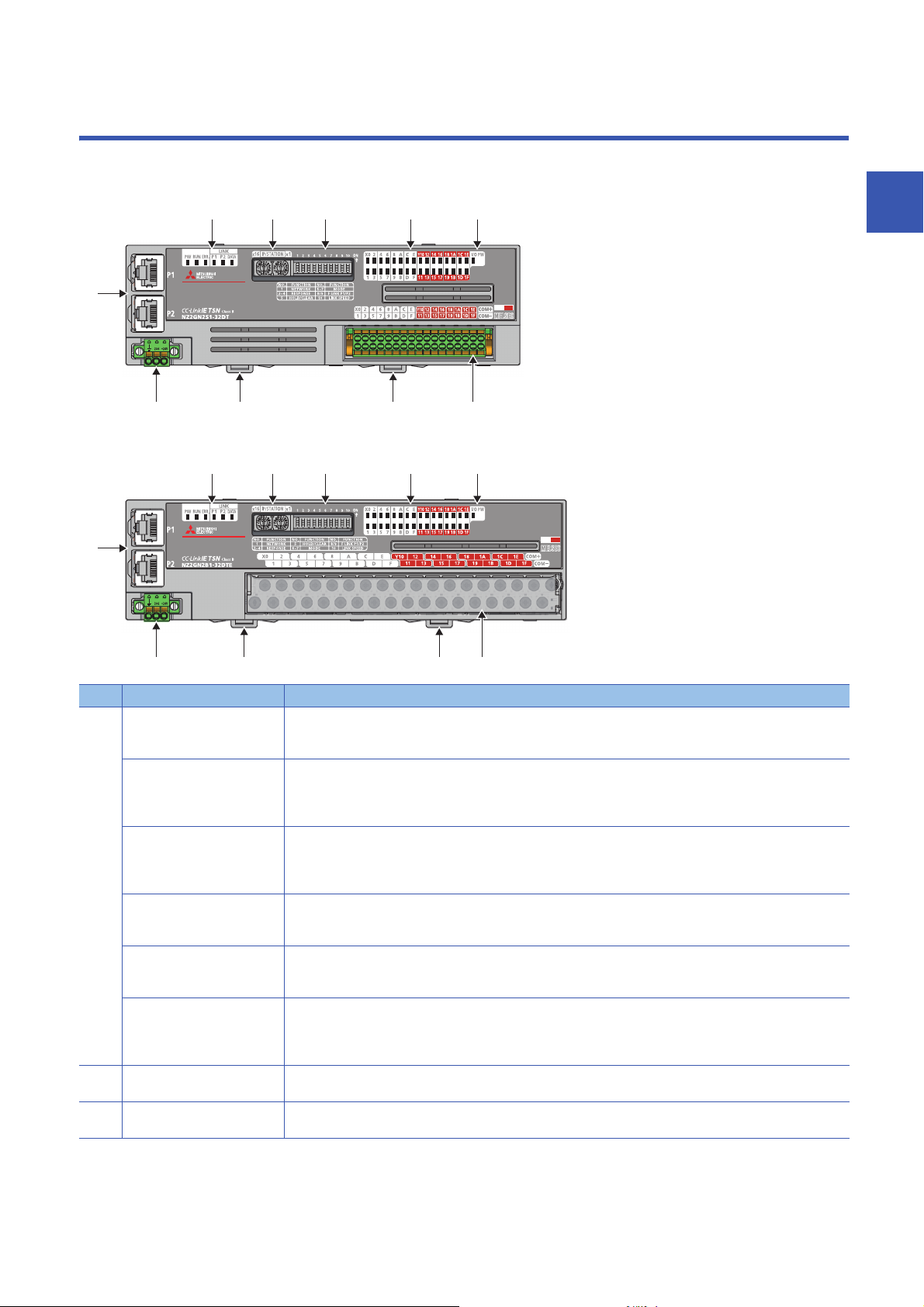
PART NAMES
This section describes part names of the I/O module.
• Spring clamp terminal block type
• Screw terminal block type
2
No. Name Application
(1) PW LED Indicates the power supply status of the I/O module.
RUN LED Indicates the operating status of the I/O module.
ERR. LED Indicates the error status of the I/O module.
P1 LINK LED Indicates the link status for P1.
P2 LINK LED Indicates the link status for P2.
DATA LINK LED
(2) IP address setting switch Sets the fourth octet of the IP address.
(3) Function setting switch Sets functions of the I/O module.
*3
On: Power supply ON
Off: Power supply OFF
On: Operating normally.
Flashing: Operating in unit test mode
Off: A major error has occurred.
On: A moderate error or major error has occurred.
Flashing: A minor error has occurred.
Off: Operating normally.
On: Link-up
Off: Linkdown in progress
On: Link-up
Off: Linkdown in progress
Indicates the data link status of the I/O module.
On: Cyclic transmission being performed
Flashing: Cyclic transmission stopped
Off: Disconnected
Page 58 IP address setting switch setting
Page 60 Function setting switch setting
2 PART NAMES
13

No. Name Application
(4) X0 LED to X1F LED Indicates the ON/OFF status of the inputs.
Y0 LED to Y1F LED Indicates the ON/OFF status of the outputs.
(5) I/O PW LED Indicates the status of the power supply from the external power supply.
(6) P1 A port for the connection to CC-Link IE TSN (RJ45 connector)
P2 Same as P1
(7) Terminal block for module
power supply and FG
(8) DIN rail hook A hook to mount an I/O module on a DIN rail
(9) I/O terminal block A terminal block for I/O power supply and I/O signals
On: Input ON
Off: Input OFF
On: Output ON
Off: Output OFF
On: External power supply ON
Off: External power supply OFF
Connect an Ethernet cable. ( Page 67 Wiring of Ethernet Cable)
There are no restrictions on the connection order of the cables for P1 and P2.
A terminal block to connect the module power supply (24VDC) and FG.
*1
*2
*1 The status of actual input signals that are externally input is indicated on the LEDs regardless of the status of the remote input signal.
*2 Output commands from the I/O module are indicated on the LEDs regardless of the status of the external power supply.
*3 "D LINK LED" or "D LINK" may be used as an abbreviation for DATA LINK LED.
I/O module status and LED status
The following table lists the correspondence between the I/O module status and the LED status.
I/O module status LED status
PW LED RUN LED DATA LINK LED ERR. LED
Disconnected On On Off
Data link in operation On On On
Reserved station setting in progress On On Flashing
Data link stop On On Flashing
Network initial setting in progress
Unit test In progress On Flashing Off Off
Normal completion On On Off Off
Abnormal
completion
Error Major error On Off
Moderate error On On
Minor error On On
*2
On On Flashing
On On Off On
*1
*1
*1
*1
*1
*1
*1
*1
On
On
Flashing
*1 Either of On, Flashing, or Off.
*2 If the master station becomes absent during network initial setting, the DATA LINK LED may flash continuously.
2 PART NAMES
14
3
SPECIFICATIONS
This chapter describes the specifications of the I/O module.
3.1
Item Specifications
Operating ambient temperature 0 to 55
Storage ambient temperature -25 to 75
Operating ambient humidity 5 to 95%RH, non-condensing
Storage ambient humidity
Vibration resistance Compliant with JIS
Shock resistance Compliant with JIS B 3502 and IEC 61131-2 (147m/, 3 times each in X, Y, and Z directions)
Operating atmosphere No corrosive gases, flammable gases, less conductive dust
Operating altitude
Installation location Inside a control panel
Overvoltage category
Pollution degree
Equipment class Class
*1 Do not use or store the I/O module under pressure higher than the atmospheric pressure of altitude 0m. Doing so may cause
malfunction. When using the I/O module under pressure, please consult your local Mitsubishi representative.
*2 If the environment satisfies the operating ambient temperature, operating ambient humidity and other conditions, the module can be
used even outside the control panel.
*3 This indicates the section of the power supply to which the equipment is assumed to be connected between the public electrical power
distribution network and the machinery within premises.
Category applies to equipment for which electrical power is supplied from fixed facilities. The surge voltage withstand level for the
equipment with the rated voltage of 300V or less is 2500V.
*4 This index indicates the degree to which conductive material is generated in terms of the environment in which the equipment is used.
Pollution degree 2 is when only non-conductive pollution occurs. A temporary conductivity caused by condensing must be expected
occasionally.
General Specifications
B 3502 and IEC
61131-2
*1
*3
*4
0 to 2000m
or less
2 or less
Frequency Constant
Under intermittent
vibration
Under continuous
vibration
*2
acceleration
5 to 8.4Hz 3.5mm 10 times each in X,
8.4 to 150Hz 9.8m/
5 to 8.4Hz 1.75mm
8.4 to 150Hz 4.9m/
Half amplitude Number of sweeps
Y, and Z directions
3
For compliance with the EMC Directive, refer to the following:
Page 125 EMC and Low Voltage Directives
3 SPECIFICATIONS
3.1 General Specifications
15

3.2
The following table shows the Ethernet communication specifications for the I/O module.
Item Description
Transmission specifications Data transmission speed 1Gbps
*1 For the maximum segment length (length between hubs), check with the manufacturer of the switching hub to be used.
Ethernet Communication Specifications
Communication mode 1000BASE-T Full-duplex
Interface RJ45 connector (AUTO MDI/MDI-X)
Maximum frame size 1518 bytes
Maximum segment length 100m
Number of cascade
connections
IP version IPv4
1000BASE-T Check with the manufacturer of the switching hub to be used.
*1
16
3 SPECIFICATIONS
3.2 Ethernet Communication Specifications

3.3
Performance Specifications
Input module
NZ2GN2S1-32D DC input module
Item NZ2GN2S1-32D
Station type Remote station
Authentication Class Authentication Class B
Number of input points 32 points
Rated input voltage 24VDC (ripple rate: 5% or less) (Allowable voltage range: 20.4 to 28.8VDC)
Rated input current 6.0mA TYP. (for 24VDC)
Maximum number of simultaneous input points 100%
ON voltage/ON current 11VDC or more/4mA or more
OFF voltage/OFF current 5VDC or less/1.5mA or less
Input resistance 3.3kΩ
Input response time OFF → ON 0ms
ON → OFF
Withstand voltage 510VAC for 1 minute between all DC external terminals and ground
Insulation resistance 10MΩ or higher between all DC external terminals and ground (500VDC insulation resistance tester)
Noise immunity
Protection degree IP2X
Wiring method for common 32 points/common (Common terminal: terminal number 33, 34) (1-wire, spring clamp terminal block
External interface Communication part RJ45 connector
Applicable wire size For power supply Stranded wire: 0.3 to 1.5 (22 to 16 AWG), terminal slot size: 2.4mm × 1.5mm
Applicable solderless
terminal
Cyclic transmission RX/RY points 32 points
Module power supply Voltage 24VDC (ripple rate: 5% or less) (Allowable voltage range: 20.4 to 28.8VDC)
Weight 0.20kg
*1 If the input response time is set to "0ms", the actual input response time is 80μs at OFF → ON, and 160μs at ON → OFF.
*2 It is the noise immunity of when the input response time setting value is other than "0ms". Note that the module is easily affected by
noise if "0ms" is set.
*3 Use bar solderless terminals for wiring.
*4 Only one wire can be inserted into a wire insertion opening. Multiple wires cannot be connected to a terminal. Connecting two or more
wires may cause a poor contact.
*2
Module power supply part Terminal block for module power supply and FG (2-piece spring clamp terminal block)
I/O part 2-piece spring clamp terminal block
For I/O Stranded wire: 0.3 to 1.5 (22 to 16 AWG)
*4
Terminal block for module
power supply and FG
Terminal block for input Page 69 Applicable solderless terminal
RWr/RWw points 4 points
Current 110mA or less (24VDC, all points ON)
*1
/0.2ms/1ms/1.5ms/5ms/10ms/20ms/70ms
(Factory default: 1ms)
Noise voltage 500Vp-p, noise width 1μs, noise frequency 25 to 60Hz (DC type noise simulator
condition)
type)
Positive common/negative common shared type
*3
Page 65 Applicable solderless terminal
3
3 SPECIFICATIONS
3.3 Performance Specifications
17
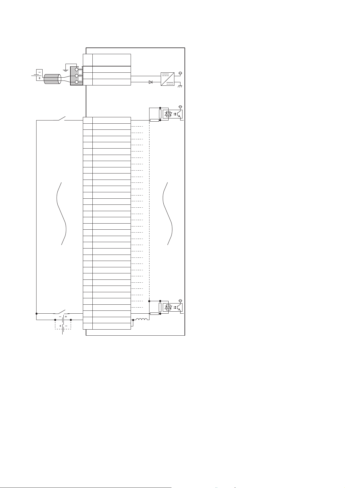
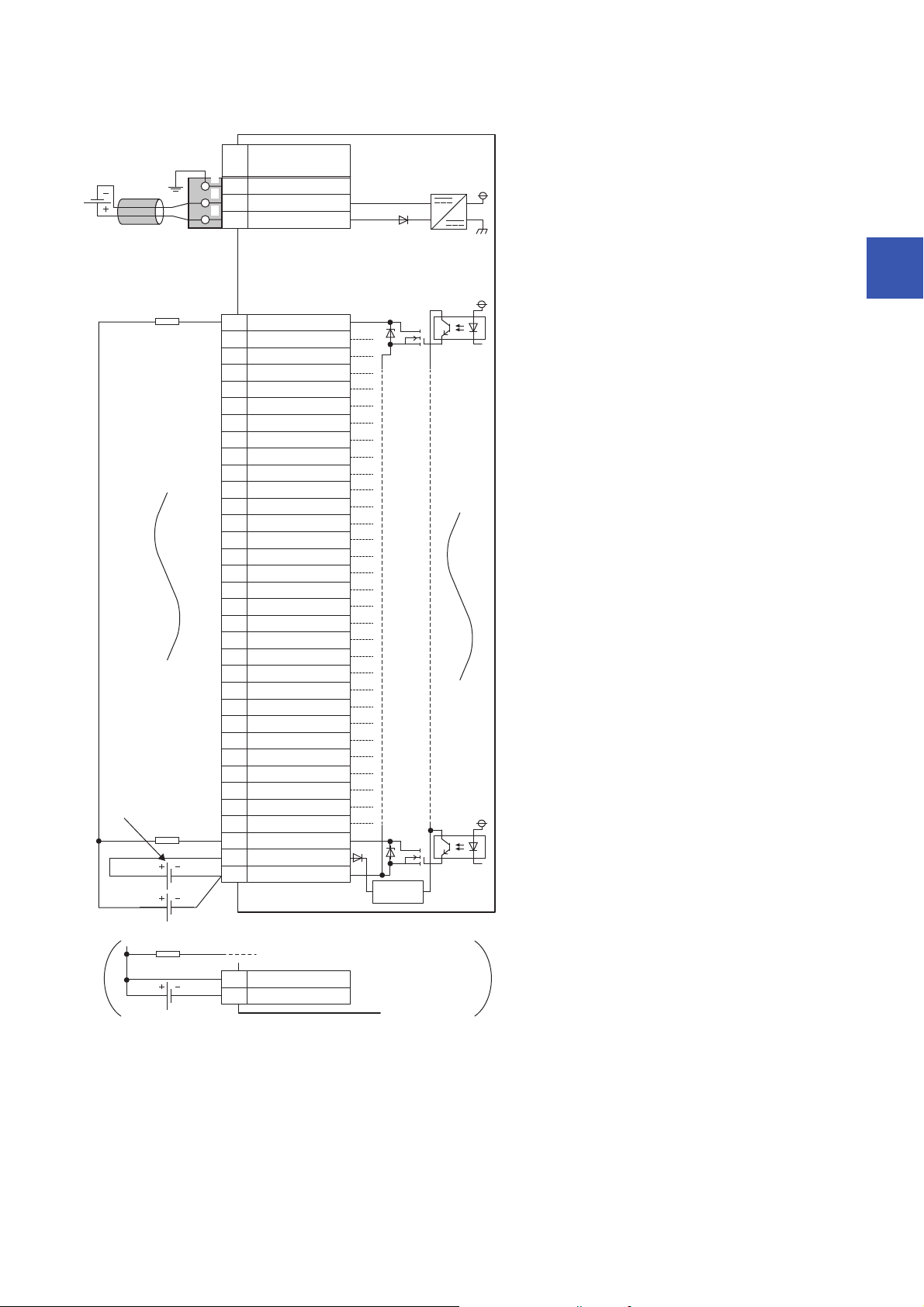
■External wiring
FG
1
2
3
UNIT POWER
CABLE
1
2
3
X01
X12
X23
X34
X45
X56
7
X78
X89
X910
XA11
XB12
XC13
XD14
XE15
XF16
X1017
X1118
X1219
X1320
X1421
X1522
X1623
X1724
X1825
X1926
X1A27
X1B28
X1C29
X1D30
X1E31
X1F32
COM33
COM34
+24V
24G
X6
Signal name
Pin
No.
Non-insulated
Terminal block
for input
*1
Terminal block for module
power supply and FG
*1
Module power
supply
*1 Only one wire can be inserted into a wire insertion opening. Multiple wires cannot be connected to a terminal. Connecting two or more
wires may cause a poor contact.
3 SPECIFICATIONS
18
3.3 Performance Specifications

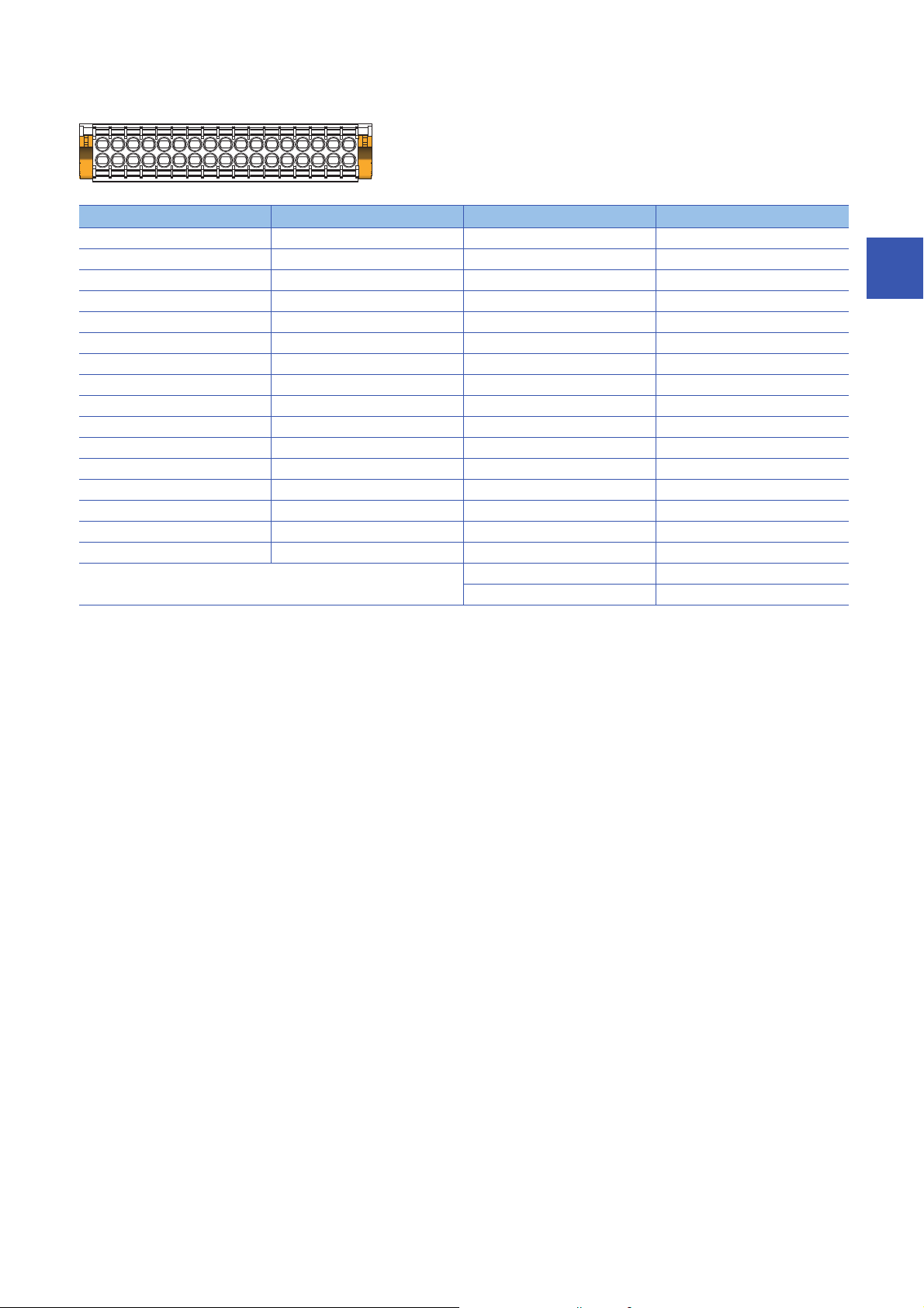
■Terminal block for input
33312927252321191715131197531
343230282624222018161412108642
Terminal number Signal name Terminal number Signal name
1X017X10
2X118X11
3X219X12
4X320X13
5X421X14
6X522X15
7X623X16
8X724X17
9X825X18
10 X9 26 X19
11 XA 27 X1 A
12 XB 28 X1B
13 XC 29 X1C
14 XD 30 X1D
15 XE 31 X1E
16 XF 32 X1F
33 COM
34 COM
3
3.3 Performance Specifications
3 SPECIFICATIONS
19

NZ2GN2B1-32D DC input module
Item NZ2GN2B1-32D
Station type Remote station
Authentication Class Authentication Class B
Number of input points 32 points
Rated input voltage 24VDC (ripple rate: 5% or less) (Allowable voltage range: 20.4 to 28.8VDC)
Rated input current 6.0mA TYP. (for 24VDC)
Maximum number of simultaneous input points 100%
ON voltage/ON current 11VDC or more/4mA or more
OFF voltage/OFF current 5VDC or less/1.5mA or less
Input resistance 3.3kΩ
Input response time OFF → ON 0ms
ON → OFF
Withstand voltage 510VAC for 1 minute between all DC external terminals and ground
Insulation resistance 10MΩ or higher between all DC external terminals and ground (500VDC insulation resistance tester)
Noise immunity
Protection degree IP2X
Wiring method for common 32 points/common (Common terminal: terminal number 33, 34) (1-wire, screw terminal block type)
External interface Communication part RJ45 connector
Applicable wire size For power supply Stranded wire: 0.3 to 1.5 (22 to 16 AWG), terminal slot size: 2.4mm × 1.5mm
Applicable solderless
terminal
Cyclic transmission RX/RY points 32 points
Module power supply Voltage 24VDC (ripple rate: 5% or less) (Allowable voltage range: 20.4 to 28.8VDC)
Weight 0.31kg
*2
Module power supply part Terminal block for module power supply and FG (2-piece spring clamp terminal block)
I/O part 34-point two-piece terminal block
For I/O Stranded wire: 0.3 to 2.0 (22 to 14 AWG)
Terminal block for module
power supply and FG
Terminal block for input Page 72 Applicable solderless terminal
RWr/RWw points 4 points
Current 110mA or less (24VDC, all points ON)
*4
*1 If the input response time is set to "0ms", the actual input response time is 80μs at OFF → ON, and 160μs at ON → OFF.
*2 It is the noise immunity of when the input response time setting value is other than "0ms". Note that the module is easily affected by
noise if "0ms" is set.
*3 Use bar solderless terminals for wiring.
*4 Only one wire can be inserted into a wire insertion opening for the terminal block for module power supply and FG. Multiple wires cannot
be connected to a terminal. Connecting two or more wires may cause a poor contact.
*1
/0.2ms/1ms/1.5ms/5ms/10ms/20ms/70ms
(Factory default: 1ms)
Noise voltage 500Vp-p, noise width 1μs, noise frequency 25 to 60Hz (DC type noise simulator
condition)
Positive common/negative common shared type
Tightening torque range for terminal screw (M3 × 5.2 screw): 0.43 to 0.57N⋅m
Tightening torque range for terminal block mounting screw (M3.5 screw): 0.68 to 0.92N⋅m
*3
Page 65 Applicable solderless terminal
20
3 SPECIFICATIONS
3.3 Performance Specifications
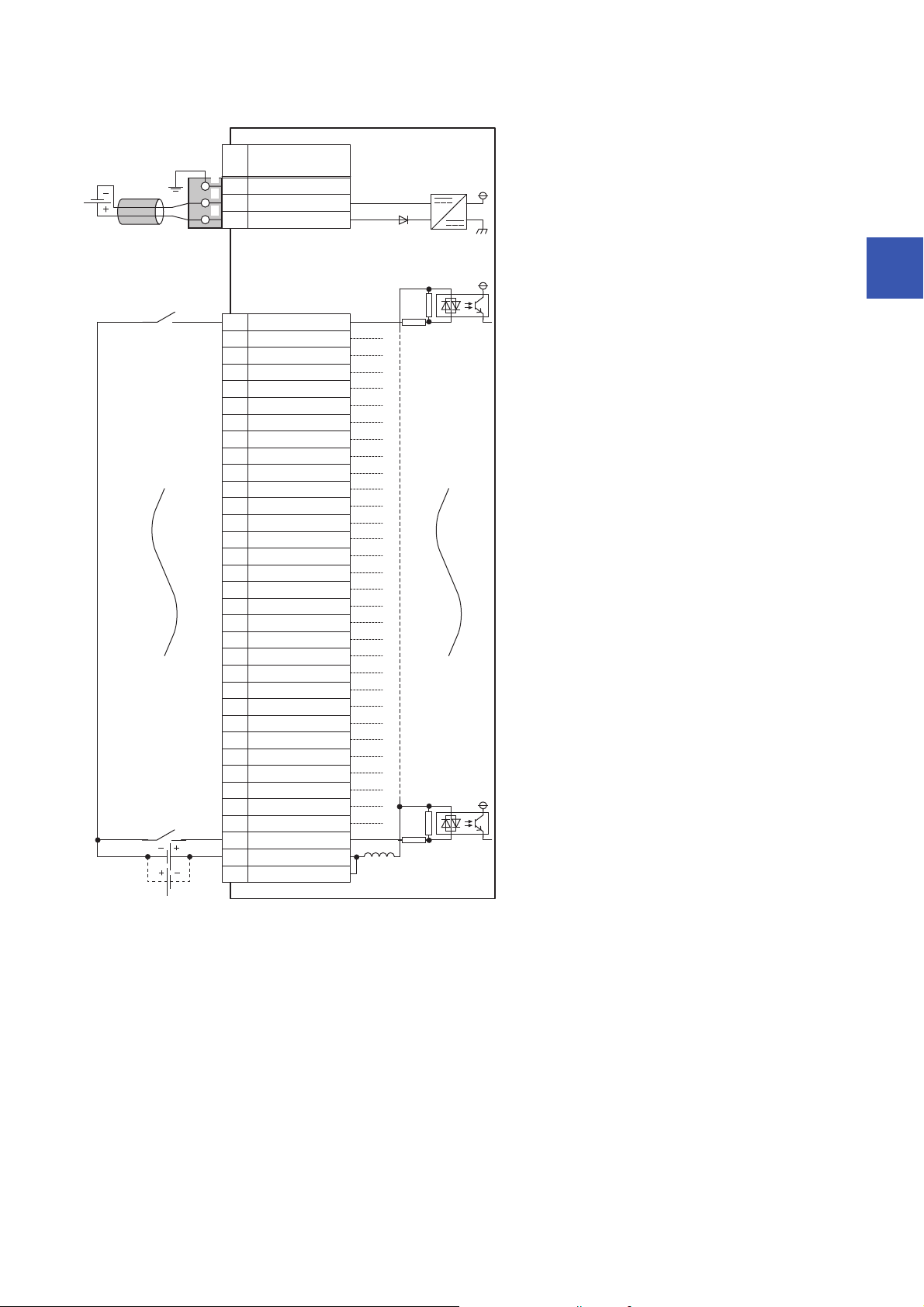
■External wiring
FG
1
2
3
UNIT POWER
CABLE
1
2
3
X01
X12
X23
X34
X45
X56
7
X78
X89
X910
XA11
XB12
XC13
XD14
XE15
XF16
X1017
X1118
X1219
X1320
X1421
X1522
X1623
X1724
X1825
X1926
X1A27
X1B28
X1C29
X1D30
X1E31
X1F32
COM33
COM34
+24V
24G
X6
Signal name
Pin
No.
Non-insulated
Terminal block
for input
Terminal block for module
power supply and FG
*1
Module power
supply
3
*1 Only one wire can be inserted into a wire insertion opening for the terminal block for module power supply and FG. Multiple wires cannot
be connected to a terminal. Connecting two or more wires may cause a poor contact.
3 SPECIFICATIONS
3.3 Performance Specifications
21

■Terminal block for input
33312927252321191715131197531
343230282624222018161412108642
Terminal number Signal name Terminal number Signal name
1X017X10
2X118X11
3X219X12
4X320X13
5X421X14
6X522X15
7X623X16
8X724X17
9X825X18
10 X9 26 X19
11 XA 27 X1 A
12 XB 28 X1B
13 XC 29 X1C
14 XD 30 X1D
15 XE 31 X1E
16 XF 32 X1F
33 COM
34 COM
22
3 SPECIFICATIONS
3.3 Performance Specifications

Output module
NZ2GN2S1-32T transistor output module
Item NZ2GN2S1-32T
Station type Remote station
Authentication Class Authentication Class B
Number of output points 32 points
Rated load voltage 12/24VDC (ripple rate: 5% or less) (Allowable voltage range: 10.2 to 28.8VDC)
Max. load current 0.5A/point, 5A/common
Maximum inrush current Current is limited by the overload protection function.
Leakage current at OFF 0.1mA or less
Max. voltage drop at ON 0.3VDC (TYP.) 0.5A, 0.6VDC (MAX.) 0.5A
Output response time OFF → ON 0.1ms or less
ON → OFF 0.8ms or less (resistive load)
Surge suppressor Zener diode
External power supply
for output part
Withstand voltage 510VAC for 1 minute between all DC external terminals and ground
Insulation resistance 10MΩ or higher between all DC external terminals and ground (500VDC insulation resistance tester)
Noise immunity Noise voltage 500Vp-p, noise width 1μs, noise frequency 25 to 60Hz (DC type noise simulator
Protection degree IP2X
Wiring method for common 32 points/common (Common terminal: terminal number 34) (1-wire, spring clamp terminal block type)
Protection function Overload protection
External interface Communication part RJ45 connector
Applicable wire size For power supply Stranded wire: 0.3 to 1.5 (22 to 16 AWG), terminal slot size: 2.4mm × 1.5mm
Applicable solderless
*2
terminal
Cyclic transmission RX/RY points 32 points
Module power supply Voltage 24VDC (ripple rate: 5% or less) (Allowable voltage range: 20.4 to 28.8VDC)
Weight 0.18kg
*1 Use bar solderless terminals for wiring.
*2 Only one wire can be inserted into a wire insertion opening. Multiple wires cannot be connected to a terminal. Connecting two or more
wires may cause a poor contact.
Voltage 12/24VDC (ripple rate: 5% or less) (Allowable voltage range: 10.2 to 28.8VDC)
Current 40mA or less (TYP. 24VDC per common) External load current is not included.
condition)
Sink type
Limited current when detecting overcurrent: 1.5 to 3.5A/point
function
Overheat protection
function
Module power supply
part
I/O part 2-piece spring clamp terminal block
For I/O Stranded wire: 0.3 to 1.5 (22 to 16 AWG)
Terminal block for
module power supply
and FG
Terminal block for output Page 69 Applicable solderless terminal
RWr/RWw poin ts 4 points
Current 120mA or less (24VDC, all points ON)
Activated to each point.
Activated to each point.
Terminal block for module power supply and FG (2-piece spring clamp terminal block)
Page 65 Applicable solderless terminal
*1
3
3 SPECIFICATIONS
3.3 Performance Specifications
23
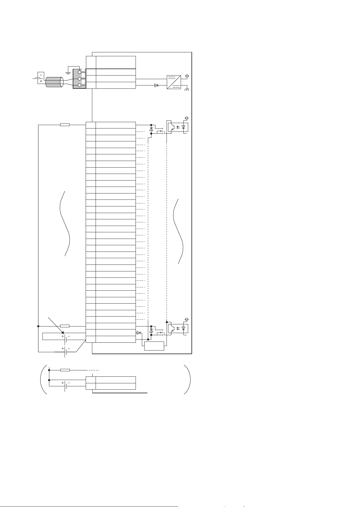
■External wiring
YF
Y0
Y1
Y2
Y3
Y4
Y5
Y6
Y7
Y8
Y9
YA
YB
YC
YD
YE
Y10
Y11
Y12
Y13
Y14
Y15
Y16
Y17
Y18
Y19
Y1A
Y1B
Y1C
Y1D
Y1E
Y1F
CTL+
COM-
1
2
3
4
5
6
7
8
9
10
11
12
13
14
15
16
17
18
19
20
21
22
23
24
25
26
27
28
29
30
31
32
33
34
33
34
CTL+
COM-
FG
1
2
3
UNIT POWER
CABLE
1
2
3
+24V
24G
Terminal block
for output
*1
Load
Load
Load
Load power
supply
External power supply for the output part
and load power supply (common)
External power supply
for the output part
Signal name
Pin
No.
Non-insulated
Terminal block for module
power supply and FG
*1
Module power
supply
Constantvoltage circuit
*1 Only one wire can be inserted into a wire insertion opening. Multiple wires cannot be connected to a terminal. Connecting two or more
wires may cause a poor contact.
24
3 SPECIFICATIONS
3.3 Performance Specifications
■Terminal block for output
33312927252321191715131197531
343230282624222018161412108642
Terminal number Signal name Terminal number Signal name
1Y017Y10
2Y118Y11
3Y219Y12
4Y320Y13
5Y421Y14
6Y522Y15
7Y623Y16
8Y724Y17
9Y825Y18
10 Y9 26 Y19
11 YA 27 Y1 A
12 YB 28 Y1B
13 YC 29 Y1C
14 YD 30 Y1D
15 YE 31 Y1E
16 YF 32 Y1F
33 CTL+
34 COM-
3
3.3 Performance Specifications
3 SPECIFICATIONS
25

NZ2GN2B1-32T transistor output module
Item NZ2GN2B1-32T
Station type Remote station
Authentication Class Authentication Class B
Number of output points 32 points
Rated load voltage 12/24VDC (ripple rate: 5% or less) (Allowable voltage range: 10.2 to 28.8VDC)
Max. load current 0.5A/point, 5A/common
Maximum inrush current Current is limited by the overload protection function.
Leakage current at OFF 0.1mA or less
Max. voltage drop at ON 0.3VDC (TYP.) 0.5A, 0.6VDC (MAX.) 0.5A
Output response time OFF → ON 0.1ms or less
ON → OFF 0.8ms or less (resistive load)
Surge suppressor Zener diode
External power supply for
output part
Withstand voltage 510VAC for 1 minute between all DC external terminals and ground
Insulation resistance 10MΩ or higher between all DC external terminals and ground (500VDC insulation resistance tester)
Noise immunity Noise voltage 500Vp-p, noise width 1μs, noise frequency 25 to 60Hz (DC type noise simulator
Protection degree IP2X
Wiring method for common 32 points/common (Common terminal: terminal number 34) (1-wire, screw terminal block type)
Protection function Overload protection
External interface Communication part RJ45 connector
Applicable wire size For power supply Stranded wire: 0.3 to 1.5 (22 to 16 AWG), terminal slot size: 2.4mm × 1.5mm
Applicable solderless
terminal
Cyclic transmission RX/RY points 32 points
Module power supply Voltage 24VDC (ripple rate: 5% or less) (Allowable voltage range: 20.4 to 28.8VDC)
Weight 0.29kg
*1 Use bar solderless terminals for wiring.
*2 Only one wire can be inserted into a wire insertion opening for the terminal block for module power supply and FG. Multiple wires cannot
be connected to a terminal. Connecting two or more wires may cause a poor contact.
Voltage 12/24VDC (ripple rate: 5% or less) (Allowable voltage range: 10.2 to 28.8VDC)
Current 40mA or less (TYP. 24VDC per common) External load current is not included.
condition)
Sink type
function
Overheat protection
function
Module power supply part Terminal block for module power supply and FG (2-piece spring clamp terminal block)
I/O part 34-point two-piece terminal block
For I/O Stranded wire: 0.3 to 2.0 (22 to 14 AWG)
Terminal block for module
power supply and FG
Terminal block for output Page 72 Applicable solderless terminal
RWr/RWw points 4 points
Current 120mA or less (24VDC, all points ON)
Limited current when detecting overcurrent: 1.5 to 3.5A/point
Activated to each point.
Activated to each point.
Tightening torque range for terminal screw (M3 × 5.2 screw): 0.43 to 0.57N⋅m
Tightening torque range for terminal block mounting screw (M3.5 screw): 0.68 to 0.92N⋅m
Page 65 Applicable solderless terminal
*2
*1
26
3 SPECIFICATIONS
3.3 Performance Specifications
■External wiring
YF
Y0
Y1
Y2
Y3
Y4
Y5
Y6
Y7
Y8
Y9
YA
YB
YC
YD
YE
Y10
Y11
Y12
Y13
Y14
Y15
Y16
Y17
Y18
Y19
Y1A
Y1B
Y1C
Y1D
Y1E
Y1F
CTL+
COM-
1
2
3
4
5
6
7
8
9
10
11
12
13
14
15
16
17
18
19
20
21
22
23
24
25
26
27
28
29
30
31
32
33
34
33
34
CTL+
COM-
FG
1
2
3
UNIT POWER
CABLE
1
2
3
+24V
24G
Terminal block
for output
Load
Load
Load
Load power
supply
External power supply for the output part
and load power supply (common)
External power supply
for the output part
Signal name
Pin
No.
Non-insulated
Terminal block for module
power supply and FG
*1
Module power
supply
Constantvoltage circuit
3
*1 Only one wire can be inserted into a wire insertion opening for the terminal block for module power supply and FG. Multiple wires cannot
be connected to a terminal. Connecting two or more wires may cause a poor contact.
3 SPECIFICATIONS
3.3 Performance Specifications
27

■Terminal block for output
33312927252321191715131197531
343230282624222018161412108642
Terminal number Signal name Terminal number Signal name
1Y017Y10
2Y118Y11
3Y219Y12
4Y320Y13
5Y421Y14
6Y522Y15
7Y623Y16
8Y724Y17
9Y825Y18
10 Y9 26 Y19
11 YA 27 Y1 A
12 YB 28 Y1B
13 YC 29 Y1C
14 YD 30 Y1D
15 YE 31 Y1E
16 YF 32 Y1F
33 CTL+
34 COM-
28
3 SPECIFICATIONS
3.3 Performance Specifications
 Loading...