

Mitsubishi NZ2GN2S1-32D, NZ2GN2B1-32TE, NZ2GN2S1-32T, NZ2GN2B1-32T, NZ2GN2S1-32DT User Manual
...Page 1

CC-Link IE TSN Remote I/O Module
User's Manual
-NZ2GN2S1-32D
-NZ2GN2B1-32D
-NZ2GN2S1-32T
-NZ2GN2B1-32T
-NZ2GN2S1-32TE
-NZ2GN2B1-32TE
-NZ2GN2S1-32DT
-NZ2GN2B1-32DT
-NZ2GN2S1-32DTE
-NZ2GN2B1-32DTE
Page 2

Page 3
SAFETY PRECAUTIONS
WARNING
Indicates that incorrect handling may cause hazardous conditions, resulting in
death or severe injury.
CAUTION
Indicates that incorrect handling may cause hazardous conditions, resulting in
minor or moderate injury or property damage.
(Read these precautions before using this product.)
Before using this product, please read this manual and the relevant manuals carefully and pay full attention to safety to handle
the product correctly.
The precautions given in this manual are concerned with this product only. For the safety precautions of the programmable
controller system, refer to the user's manual for the CPU module used.
In this manual, the safety precautions are classified into two levels: " WARNING" and " CAUTION".
Under some circumstances, failure to observe the precautions given under " CAUTION" may lead to serious
consequences.
Observe the precautions of both levels because they are important for personal and system safety.
Make sure that the end users read this manual and then keep the manual in a safe place for future reference.
[Design Precautions]
WARNING
● In the case of a communication failure in the network, data of the master station are held. Check Data
link status (each station) (SW00B0 to SW00B7) and configure an interlock circuit in the program to
ensure that the entire system will operate safely.
● When the module is disconnected due to a communication failure in the network or the CPU module is
in the STOP state, outputs are held or turned off according to the output HOLD/CLEAR setting.
Configure an interlock circuit in the program to ensure that the entire system will always operate
safely even in such a case. If not, an accident may occur due to an incorrect output or malfunction.
● Outputs may remain on or off due to a failure of the module. Configure an external circuit for
monitoring output signals that could cause a serious accident.
● Do not use any "use prohibited" signals as a remote input or output signal. These signals are reserved
for system use. Do not write any data to the "use prohibited" areas in the remote register. If these
operations are performed, an accident may occur due to an incorrect output or malfunction.
● To maintain the safety of the programmable controller system against unauthorized access from
external devices via the network, take appropriate measures. To maintain the safety against
unauthorized access via the Internet, take measures such as installing a firewall.
[Design Precautions]
CAUTION
● Do not install the control lines or communication cables together with the main circuit lines or power
cables. Keep a distance of 100mm or more between them. Failure to do so may result in malfunction
due to noise.
● During control of an inductive load such as a lamp, heater, or solenoid valve, a large current
(approximately ten times greater than normal) may flow when the output is turned from off to on.
Therefore, use a module that has a sufficient current rating.
1
Page 4
[Installation Precautions]
WARNING
● Shut off the external power supply (all phases) used in the system before mounting or removing a
module. Failure to do so may result in electric shock or cause the module to fail or malfunction.
[Installation Precautions]
CAUTION
● Use the module in an environment that meets the general specifications in this manual. Failure to do
so may result in electric shock, fire, malfunction, or damage to or deterioration of the product.
● Do not directly touch any conductive parts and electronic components of the module. Doing so can
cause malfunction or failure of the module.
● Securely connect the cable connectors. Poor contact may cause malfunction.
[Wiring Precautions]
WARNING
● Shut off the external power supply (all phases) used in the system before wiring. Failure to do so may
result in electric shock or cause the module to fail or malfunction.
2
Page 5

[Wiring Precautions]
CAUTION
● Individually ground the FG terminal of the programmable controller with a ground resistance of 100
ohms or less. Failure to do so may result in electric shock or malfunction.
● Tighten any unused terminal screws within the specified torque range. Undertightening can cause a
short circuit due to contact with a solderless terminal.
● Use applicable solderless terminals and tighten them within the specified torque range. If any spade
solderless terminal is used, it may be disconnected when a terminal block screw comes loose,
resulting in failure.
● Check the rated voltage and terminal layout before wiring to the module, and connect the cables
correctly. Connecting a power supply with a different voltage rating or incorrect wiring may cause a fire
or failure.
● Tighten the terminal block screws within the specified torque range. Undertightening can cause short
circuit, fire, or malfunction. Overtightening can damage the screw and/or module, resulting in drop,
short circuit, fire, or malfunction.
● Prevent foreign matter such as dust or wire chips from entering the module. Such foreign matter can
cause a fire, failure, or malfunction.
● Place the cables in a duct or clamp them. If not, dangling cables may swing or inadvertently be pulled,
resulting in malfunction or damage to modules or cables.
In addition, the weight of the cables may put stress on modules in an environment of strong vibrations
and shocks.
● Do not install the control lines or communication cables together with the main circuit lines or power
cables. Keep a distance of 100mm or more between them. Failure to do so may result in malfunction
due to noise.
● When disconnecting the cable from the module, do not pull the cable by the cable part. For the cable
with connector, hold the connector part of the cable. For the cable connected to the terminal block,
loosen the terminal screw. Pulling the cable connected to the module may result in malfunction or
damage to the module or cable.
● When an overcurrent caused by an error of an external device or a failure of the programmable
controller flows for a long time, it may cause smoke and fire. To prevent this, configure an external
safety circuit, such as a fuse.
● Mitsubishi programmable controllers must be installed in control panels. Wiring and replacement of a
module must be performed by qualified maintenance personnel with knowledge of protection against
electric shock. For wiring methods, refer to "INSTALLATION AND WIRING" in this manual.
3
Page 6
[Startup and Maintenance Precautions]
WARNING
● Do not touch any terminal while power is on. Doing so will cause electric shock or malfunction.
● Shut off the external power supply (all phases) used in the system before cleaning the module or
retightening the terminal block screws or connector screws. Failure to do so may cause the module to
fail or malfunction.
[Startup and Maintenance Precautions]
CAUTION
● Do not disassemble or modify the module. Doing so may cause failure, malfunction, injury, or a fire.
● Do not drop or apply strong shock to the module. Doing so may damage the module.
● Use any radio communication device such as a cellular phone or PHS (Personal Handy-phone
System) more than 25cm away from wiring as well as away in all directions from the programmable
controller. Failure to do so may cause malfunction.
● Shut off the external power supply (all phases) used in the system before mounting or removing a
module. Failure to do so may cause the module to fail or malfunction.
● After the first use of the product, do not mount/remove the terminal block to/from the module more
than 50 times (IEC 61131-2/JIS B 3502 compliant). Exceeding the limit may cause malfunction.
● Before handling the module or connection cables, touch a conducting object such as a grounded
metal to discharge the static electricity from the human body. Failure to do so may cause the module
to fail or malfunction.
● Startup and maintenance of a control panel must be performed by qualified maintenance personnel
with knowledge of protection against electric shock. Lock the control panel so that only qualified
maintenance personnel can operate it.
[Disposal Precautions]
CAUTION
● When disposing of this product, treat it as industrial waste.
4
Page 7

CONDITIONS OF USE FOR THE PRODUCT
(1) Mitsubishi programmable controller ("the PRODUCT") shall be used in conditions;
i) where any problem, fault or failure occurring in the PRODUCT, if any, shall not lead to any major or serious accident;
and
ii) where the backup and fail-safe function are systematically or automatically provided outside of the PRODUCT for the
case of any problem, fault or failure occurring in the PRODUCT.
(2) The PRODUCT has been designed and manufactured for the purpose of being used in general industries.
MITSUBISHI SHALL HAVE NO RESPONSIBILITY OR LIABILITY (INCLUDING, BUT NOT LIMITED TO ANY AND ALL
RESPONSIBILITY OR LIABILITY BASED ON CONTRACT, WARRANTY, TORT, PRODUCT LIABILITY) FOR ANY
INJURY OR DEATH TO PERSONS OR LOSS OR DAMAGE TO PROPERTY CAUSED BY the PRODUCT THAT ARE
OPERATED OR USED IN APPLICATION NOT INTENDED OR EXCLUDED BY INSTRUCTIONS, PRECAUTIONS, OR
WARNING CONTAINED IN MITSUBISHI'S USER, INSTRUCTION AND/OR SAFETY MANUALS, TECHNICAL
BULLETINS AND GUIDELINES FOR the PRODUCT.
("Prohibited Application")
Prohibited Applications include, but not limited to, the use of the PRODUCT in;
• Nuclear Power Plants and any other power plants operated by Power companies, and/or any other cases in which the
public could be affected if any problem or fault occurs in the PRODUCT.
• Railway companies or Public service purposes, and/or any other cases in which establishment of a special quality
assurance system is required by the Purchaser or End User.
• Aircraft or Aerospace, Medical applications, Train equipment, transport equipment such as Elevator and Escalator,
Incineration and Fuel devices, Vehicles, Manned transportation, Equipment for Recreation and Amusement, and
Safety devices, handling of Nuclear or Hazardous Materials or Chemicals, Mining and Drilling, and/or other
applications where there is a significant risk of injury to the public or property.
Notwithstanding the above restrictions, Mitsubishi may in its sole discretion, authorize use of the PRODUCT in one or
more of the Prohibited Applications, provided that the usage of the PRODUCT is limited only for the specific
applications agreed to by Mitsubishi and provided further that no special quality assurance or fail-safe, redundant or
other safety features which exceed the general specifications of the PRODUCTs are required. For details, please
contact the Mitsubishi representative in your region.
5
Page 8

INTRODUCTION
Thank you for purchasing the CC-Link IE TSN remote I/O module (hereafter referred to as I/O module).
This manual describes the procedures, system configuration, parameter settings, functions, and troubleshooting of the
relevant products listed below.
Before using this product, please read this manual and the relevant manuals carefully and develop familiarity with the
functions and performance of the I/O module to handle the product correctly.
When applying the program examples introduced in this manual to an actual system, ensure the applicability and confirm that
it will not cause system control problems.
Relevant products: NZ2GN2S1-32D, NZ2GN2B1-32D, NZ2GN2S1-32T, NZ2GN2B1-32T, NZ2GN2S1-32TE, NZ2GN2B1-
32TE, NZ2GN2S1-32DT, NZ2GN2B1-32DT, NZ2GN2S1-32DTE, NZ2GN2B1-32DTE
Unless otherwise specified, this manual describes the program examples in which the remote I/O signals and
remote registers are assigned for an I/O module as follows.
• Remote input signals: RX0 to RX1F
• Remote output signals: RY0 to RY1F
• Remote register: RWr0 to RWrF
• Remote register: RWw0 to RWwF
For the assignment of remote I/O signals and remote registers, refer to the following.
MELSEC iQ-R CC-Link IE TSN User's Manual (Application)
6
Page 9

CONTENTS
SAFETY PRECAUTIONS . . . . . . . . . . . . . . . . . . . . . . . . . . . . . . . . . . . . . . . . . . . . . . . . . . . . . . . . . . . . . . . . . . . .1
CONDITIONS OF USE FOR THE PRODUCT . . . . . . . . . . . . . . . . . . . . . . . . . . . . . . . . . . . . . . . . . . . . . . . . . . . .5
INTRODUCTION. . . . . . . . . . . . . . . . . . . . . . . . . . . . . . . . . . . . . . . . . . . . . . . . . . . . . . . . . . . . . . . . . . . . . . . . . . .6
RELEVANT MANUALS . . . . . . . . . . . . . . . . . . . . . . . . . . . . . . . . . . . . . . . . . . . . . . . . . . . . . . . . . . . . . . . . . . . . . .9
TERMS . . . . . . . . . . . . . . . . . . . . . . . . . . . . . . . . . . . . . . . . . . . . . . . . . . . . . . . . . . . . . . . . . . . . . . . . . . . . . . . . .10
GENERIC TERMS AND ABBREVIATIONS. . . . . . . . . . . . . . . . . . . . . . . . . . . . . . . . . . . . . . . . . . . . . . . . . . . . . .10
CHAPTER 1 PRODUCT LINEUP 11
1.1 List of Products . . . . . . . . . . . . . . . . . . . . . . . . . . . . . . . . . . . . . . . . . . . . . . . . . . . . . . . . . . . . . . . . . . . . . . . . . 11
Input modules . . . . . . . . . . . . . . . . . . . . . . . . . . . . . . . . . . . . . . . . . . . . . . . . . . . . . . . . . . . . . . . . . . . . . . . . . . . 11
Output modules . . . . . . . . . . . . . . . . . . . . . . . . . . . . . . . . . . . . . . . . . . . . . . . . . . . . . . . . . . . . . . . . . . . . . . . . . . 11
I/O combined module . . . . . . . . . . . . . . . . . . . . . . . . . . . . . . . . . . . . . . . . . . . . . . . . . . . . . . . . . . . . . . . . . . . . . 11
CHAPTER 2 PART NAMES 13
CHAPTER 3 SPECIFICATIONS 15
3.1 General Specifications . . . . . . . . . . . . . . . . . . . . . . . . . . . . . . . . . . . . . . . . . . . . . . . . . . . . . . . . . . . . . . . . . . .15
3.2 Ethernet Communication Specifications . . . . . . . . . . . . . . . . . . . . . . . . . . . . . . . . . . . . . . . . . . . . . . . . . . . . 16
3.3 Performance Specifications . . . . . . . . . . . . . . . . . . . . . . . . . . . . . . . . . . . . . . . . . . . . . . . . . . . . . . . . . . . . . . .17
Input module . . . . . . . . . . . . . . . . . . . . . . . . . . . . . . . . . . . . . . . . . . . . . . . . . . . . . . . . . . . . . . . . . . . . . . . . . . . .17
Output module. . . . . . . . . . . . . . . . . . . . . . . . . . . . . . . . . . . . . . . . . . . . . . . . . . . . . . . . . . . . . . . . . . . . . . . . . . .23
I/O combined module . . . . . . . . . . . . . . . . . . . . . . . . . . . . . . . . . . . . . . . . . . . . . . . . . . . . . . . . . . . . . . . . . . . . . 35
3.4 Function List . . . . . . . . . . . . . . . . . . . . . . . . . . . . . . . . . . . . . . . . . . . . . . . . . . . . . . . . . . . . . . . . . . . . . . . . . . .49
CONTENTS
CHAPTER 4 PROCEDURES BEFORE OPERATION 50
CHAPTER 5 SYSTEM CONFIGURATION 52
5.1 Applicable Systems. . . . . . . . . . . . . . . . . . . . . . . . . . . . . . . . . . . . . . . . . . . . . . . . . . . . . . . . . . . . . . . . . . . . . .52
CHAPTER 6 INSTALLATION AND WIRING 54
6.1 Before Using the I/O Modules . . . . . . . . . . . . . . . . . . . . . . . . . . . . . . . . . . . . . . . . . . . . . . . . . . . . . . . . . . . . . 54
Input modules . . . . . . . . . . . . . . . . . . . . . . . . . . . . . . . . . . . . . . . . . . . . . . . . . . . . . . . . . . . . . . . . . . . . . . . . . . .54
Output modules . . . . . . . . . . . . . . . . . . . . . . . . . . . . . . . . . . . . . . . . . . . . . . . . . . . . . . . . . . . . . . . . . . . . . . . . . . 55
I/O combined module . . . . . . . . . . . . . . . . . . . . . . . . . . . . . . . . . . . . . . . . . . . . . . . . . . . . . . . . . . . . . . . . . . . . . 57
6.2 Setting Switch . . . . . . . . . . . . . . . . . . . . . . . . . . . . . . . . . . . . . . . . . . . . . . . . . . . . . . . . . . . . . . . . . . . . . . . . . .58
IP address setting switch setting . . . . . . . . . . . . . . . . . . . . . . . . . . . . . . . . . . . . . . . . . . . . . . . . . . . . . . . . . . . . .58
Function setting switch setting. . . . . . . . . . . . . . . . . . . . . . . . . . . . . . . . . . . . . . . . . . . . . . . . . . . . . . . . . . . . . . . 60
6.3 Installation Environment and Installation Position . . . . . . . . . . . . . . . . . . . . . . . . . . . . . . . . . . . . . . . . . . . . 62
Installation environment. . . . . . . . . . . . . . . . . . . . . . . . . . . . . . . . . . . . . . . . . . . . . . . . . . . . . . . . . . . . . . . . . . . .62
Installation position . . . . . . . . . . . . . . . . . . . . . . . . . . . . . . . . . . . . . . . . . . . . . . . . . . . . . . . . . . . . . . . . . . . . . . .62
Installation direction. . . . . . . . . . . . . . . . . . . . . . . . . . . . . . . . . . . . . . . . . . . . . . . . . . . . . . . . . . . . . . . . . . . . . . .63
6.4 Installation . . . . . . . . . . . . . . . . . . . . . . . . . . . . . . . . . . . . . . . . . . . . . . . . . . . . . . . . . . . . . . . . . . . . . . . . . . . . . 64
Mounting the modules on a DIN rail . . . . . . . . . . . . . . . . . . . . . . . . . . . . . . . . . . . . . . . . . . . . . . . . . . . . . . . . . . 64
6.5 Wiring of Terminal Block for Module Power Supply and FG. . . . . . . . . . . . . . . . . . . . . . . . . . . . . . . . . . . . . 65
6.6 Wiring of Ethernet Cable. . . . . . . . . . . . . . . . . . . . . . . . . . . . . . . . . . . . . . . . . . . . . . . . . . . . . . . . . . . . . . . . . . 67
6.7 Wiring of External Device and I/O Terminal Block . . . . . . . . . . . . . . . . . . . . . . . . . . . . . . . . . . . . . . . . . . . . .69
Wiring of spring clamp terminal block . . . . . . . . . . . . . . . . . . . . . . . . . . . . . . . . . . . . . . . . . . . . . . . . . . . . . . . . . 69
Wiring of screw terminal block. . . . . . . . . . . . . . . . . . . . . . . . . . . . . . . . . . . . . . . . . . . . . . . . . . . . . . . . . . . . . . .72
7
Page 10

CHAPTER 7 PARAMETER SETTING 74
7.1 Network Configuration Setting. . . . . . . . . . . . . . . . . . . . . . . . . . . . . . . . . . . . . . . . . . . . . . . . . . . . . . . . . . . . . 74
CHAPTER 8 FUNCTIONS 76
8.1 Input Response Time Setting Function. . . . . . . . . . . . . . . . . . . . . . . . . . . . . . . . . . . . . . . . . . . . . . . . . . . . . . 76
8.2 Output HOLD/CLEAR Setting Function. . . . . . . . . . . . . . . . . . . . . . . . . . . . . . . . . . . . . . . . . . . . . . . . . . . . . .77
8.3 Output ON/OFF Information Hold Function . . . . . . . . . . . . . . . . . . . . . . . . . . . . . . . . . . . . . . . . . . . . . . . . . . 78
8.4 Protection Function. . . . . . . . . . . . . . . . . . . . . . . . . . . . . . . . . . . . . . . . . . . . . . . . . . . . . . . . . . . . . . . . . . . . . . 79
8.5 Module Power Supply Voltage Drop Detection Function . . . . . . . . . . . . . . . . . . . . . . . . . . . . . . . . . . . . . . .80
8.6 External Power Supply Monitoring Function . . . . . . . . . . . . . . . . . . . . . . . . . . . . . . . . . . . . . . . . . . . . . . . . .80
CHAPTER 9 PROGRAMMING 81
9.1 Precautions for Programming . . . . . . . . . . . . . . . . . . . . . . . . . . . . . . . . . . . . . . . . . . . . . . . . . . . . . . . . . . . . .81
9.2 Program Example . . . . . . . . . . . . . . . . . . . . . . . . . . . . . . . . . . . . . . . . . . . . . . . . . . . . . . . . . . . . . . . . . . . . . . . 82
CHAPTER 10 MAINTENANCE AND INSPECTION 87
CHAPTER 11 TROUBLESHOOTING 89
11.1 CC-Link IE TSN/CC-Link IE Field Diagnostics . . . . . . . . . . . . . . . . . . . . . . . . . . . . . . . . . . . . . . . . . . . . . . . . 89
11.2 Checking the LEDs . . . . . . . . . . . . . . . . . . . . . . . . . . . . . . . . . . . . . . . . . . . . . . . . . . . . . . . . . . . . . . . . . . . . . .90
11.3 Unit Test . . . . . . . . . . . . . . . . . . . . . . . . . . . . . . . . . . . . . . . . . . . . . . . . . . . . . . . . . . . . . . . . . . . . . . . . . . . . . . .94
11.4 Troubleshooting by Symptom . . . . . . . . . . . . . . . . . . . . . . . . . . . . . . . . . . . . . . . . . . . . . . . . . . . . . . . . . . . . . 95
11.5 Examples of Troubles with the I/O Module . . . . . . . . . . . . . . . . . . . . . . . . . . . . . . . . . . . . . . . . . . . . . . . . . . . 96
Troubleshooting for input circuit . . . . . . . . . . . . . . . . . . . . . . . . . . . . . . . . . . . . . . . . . . . . . . . . . . . . . . . . . . . . . 96
Troubleshooting for output circuit . . . . . . . . . . . . . . . . . . . . . . . . . . . . . . . . . . . . . . . . . . . . . . . . . . . . . . . . . . . . 99
11.6 Method for Checking Error Codes . . . . . . . . . . . . . . . . . . . . . . . . . . . . . . . . . . . . . . . . . . . . . . . . . . . . . . . . . 106
11.7 Error Code List . . . . . . . . . . . . . . . . . . . . . . . . . . . . . . . . . . . . . . . . . . . . . . . . . . . . . . . . . . . . . . . . . . . . . . . . 108
APPENDICES 110
Appendix 1 Remote I/O Signal . . . . . . . . . . . . . . . . . . . . . . . . . . . . . . . . . . . . . . . . . . . . . . . . . . . . . . . . . . . . . . . . . 110
List of remote I/O signals. . . . . . . . . . . . . . . . . . . . . . . . . . . . . . . . . . . . . . . . . . . . . . . . . . . . . . . . . . . . . . . . . . 110
Details of remote input signals . . . . . . . . . . . . . . . . . . . . . . . . . . . . . . . . . . . . . . . . . . . . . . . . . . . . . . . . . . . . . 113
Details of remote output signals . . . . . . . . . . . . . . . . . . . . . . . . . . . . . . . . . . . . . . . . . . . . . . . . . . . . . . . . . . . . 113
Appendix 2 Remote Register . . . . . . . . . . . . . . . . . . . . . . . . . . . . . . . . . . . . . . . . . . . . . . . . . . . . . . . . . . . . . . . . . . 114
List of remote registers . . . . . . . . . . . . . . . . . . . . . . . . . . . . . . . . . . . . . . . . . . . . . . . . . . . . . . . . . . . . . . . . . . . 114
Details of Remote Registers . . . . . . . . . . . . . . . . . . . . . . . . . . . . . . . . . . . . . . . . . . . . . . . . . . . . . . . . . . . . . . . 116
Appendix 3 Processing Time . . . . . . . . . . . . . . . . . . . . . . . . . . . . . . . . . . . . . . . . . . . . . . . . . . . . . . . . . . . . . . . . . . 124
Appendix 4 EMC and Low Voltage Directives . . . . . . . . . . . . . . . . . . . . . . . . . . . . . . . . . . . . . . . . . . . . . . . . . . . . . 125
Measures to comply with the EMC Directive . . . . . . . . . . . . . . . . . . . . . . . . . . . . . . . . . . . . . . . . . . . . . . . . . . . 125
Requirements to compliance with the Low Voltage Directive . . . . . . . . . . . . . . . . . . . . . . . . . . . . . . . . . . . . . .129
Appendix 5 How to Check Production Information . . . . . . . . . . . . . . . . . . . . . . . . . . . . . . . . . . . . . . . . . . . . . . . .130
Appendix 6 External Dimensions . . . . . . . . . . . . . . . . . . . . . . . . . . . . . . . . . . . . . . . . . . . . . . . . . . . . . . . . . . . . . . . 131
INDEX 132
REVISIONS. . . . . . . . . . . . . . . . . . . . . . . . . . . . . . . . . . . . . . . . . . . . . . . . . . . . . . . . . . . . . . . . . . . . . . . . . . . . .134
WARRANTY . . . . . . . . . . . . . . . . . . . . . . . . . . . . . . . . . . . . . . . . . . . . . . . . . . . . . . . . . . . . . . . . . . . . . . . . . . . .135
TRADEMARKS . . . . . . . . . . . . . . . . . . . . . . . . . . . . . . . . . . . . . . . . . . . . . . . . . . . . . . . . . . . . . . . . . . . . . . . . . .136
8
Page 11

RELEVANT MANUALS
Manual name [manual number] Description Available form
CC-Link IE TSN Remote I/O Module User's Manual
[SH-082135ENG] (this manual)
MELSEC iQ-R CC-Link IE TSN User's Manual
(Startup)
[SH-082127ENG]
MELSEC iQ-R CC-Link IE TSN User's Manual
(Application)
[SH-082129ENG]
e-Manual refers to the Mitsubishi Electric FA electronic book manuals that can be browsed using a dedicated
tool.
e-Manual has the following features:
• Required information can be cross-searched in multiple manuals.
• Other manuals can be accessed from the links in the manual.
• The hardware specifications of each part can be found from the product figures.
• Pages that users often browse can be bookmarked.
• Sample programs can be copied to an engineering tool.
Part names, specifications, procedures before operation, system
configuration, installation, wiring, parameter settings, functions,
programming, and troubleshooting of the I/O module
Specifications, procedures before operation, system configuration, wiring,
and communication examples of CC-Link IE TSN
Functions, parameter settings, troubleshooting, I/O signals, and buffer
memory of CC-Link IE TSN
Print book
e-Manual
PDF
Print book
e-Manual
PDF
Print book
e-Manual
PDF
9
Page 12

TERMS
Unless otherwise specified, this manual uses the following terms.
Term Description
Authentication Class A group of modules and switching hubs compatible with CC-Link IE TSN, ranked according to the functions and
Cyclic transmission A function by which data are periodically exchanged among stations on the same network using link devices
Data link Cyclic transmission, transient transmission
Disconnection A process of stopping data link if a data link error occurs
Engineering tool A tool used for setting up programmable controllers, programming, debugging, and maintenance
Link device A device in a module on CC-Link IE TSN
Link special register (SW) Word data that indicates the operating status and data link status of a module on CC-Link IE TSN
Link special relay (SB) Bit data that indicates the operating status and data link status of a module on CC-Link IE TSN
Local station A station that performs cyclic transmission and transient transmission with the master station and other local stations.
Master station A station that controls the entire network. This station can perform cyclic transmission and transient transmission with all
Remote station A station that exchanges I/O signals (bit data) and I/O data (word data) with another station by cyclic transmission. This
Reserved station A station reserved for future use. This station is not actually connected, but counted as a connected station.
Return A process of restarting data link when a station recovers from an error
RWr Remote register of link devices. RWr refers to word data input from a slave station to the master station (For some areas
RWw Remote register of link devices. RWw refers to word data output from the master station to a slave station (For some
RX Remote input of link devices. Bit data input from a slave station to the master station (For some areas in a local station,
RY Remote output of link devices. Bit data output from the master station to a slave station (For some areas in a local
Slave station A station other than a master station: a local station, a remote station
Transient transmission A function of communication with another station, which is used when requested by a dedicated instruction or an
performance by the CC-Link Partner Association (www.cc-link.org). The I/O module is categorized as Authentication
Class B.
The station is controlled by programs in the CPU module or other equivalent modules on the station.
stations. Only one master station can be used in a network.
station can perform transient transmission.
in a local station, data are input in the opposite direction.)
areas in a local station, data are output in the opposite direction.)
data are input in the opposite direction.)
station, data are output in the opposite direction.)
engineering tool
GENERIC TERMS AND ABBREVIATIONS
Generic term and
abbreviation
A/D converter module A CC-Link IE TSN analog-digital converter module
CC-Link IE TSN remote module An A/D converter module, a D/A converter module, an I/O module
D/A converter module A CC-Link IE TSN digital-analog converter module
Output module A module where a digital signal can be output
I/O module A CC-Link IE TSN remote I/O module
I/O combined module A module where a digital signal can be input and output
Input module A module where a digital signal can be input
Description
10
Page 13

1
PRODUCT LINEUP
1
1.1
List of Products
Input modules
Module name Input specifications Module power
supply current
DC input module Positive common/
negative common
shared type
Spring clamp terminal block
24VDC, 32 points
Screw terminal block
24VDC, 32 points
110mA 0.20kg NZ2GN2S1-32D Page 17
110mA 0.31kg NZ2GN2B1-32D Page 20
Output modules
Module name Output specifications Module power
supply current
Transistor output
module
Sink type Spring clamp terminal block
12/24VDC, 0.5A/point, 32 points
Screw terminal block
12/24VDC, 0.5A/point, 32 points
Source type Spring clamp terminal block
12/24VDC, 0.5A/point, 32 points
Screw terminal block
12/24VDC, 0.5A/point, 32 points
120mA 0.18kg NZ2GN2S1-32T Page 23
120mA 0.29kg NZ2GN2B1-32T Page 26
120mA 0.18kg NZ2GN2S1-32TE Page 29
120mA 0.29kg NZ2GN2B1-32TE Page 32
Weight Model Reference
NZ2GN2S1-32D DC
input module
NZ2GN2B1-32D DC
input module
Weight Model Reference
NZ2GN2S1-32T
transistor output module
NZ2GN2B1-32T
transistor output module
NZ2GN2S1-32TE
transistor output module
NZ2GN2B1-32TE
transistor output module
I/O combined module
Module name Input
specifications
DC input/
transistor output
module
• Input part: Positive
common type
• Output part: Sink
type
• Input part: Positive
common type
• Output part: Sink
type
• Input part: Negative
common type
• Output part: Source
type
• Input part: Negative
common type
• Output part: Source
type
Spring clamp
terminal block
24VDC, 16 points
Screw terminal
block
24VDC, 16 points
Spring clamp
terminal block
24VDC, 16 points
Screw terminal
block
24VDC, 16 points
Output
specifications
Spring clamp
terminal block
24VDC, 0.5A/
point, 16 points
Screw terminal
block
24VDC, 0.5A/
point, 16 points
Spring clamp
terminal block
24VDC, 0.5A/
point, 16 points
Screw terminal
block
24VDC, 0.5A/
point, 16 points
Module
power
supply
current
110mA 0.20kg NZ2GN2S1-32DT Page 35
110mA 0.31kg NZ2GN2B1-32DT Page 39
110mA 0.20kg NZ2GN2S1-32DTE Page 43
110mA 0.31kg NZ2GN2B1-32DTE Page 46
Weight Model Reference
NZ2GN2S1-32DT DC
input/transistor output
module
NZ2GN2B1-32DT DC
input/transistor output
module
NZ2GN2S1-32DTE
DC input/transistor
output module
NZ2GN2B1-32DTE
DC input/transistor
output module
1 PRODUCT LINEUP
1.1 List of Products
11
Page 14

MEMO
12
1 PRODUCT LINEUP
1.1 List of Products
Page 15
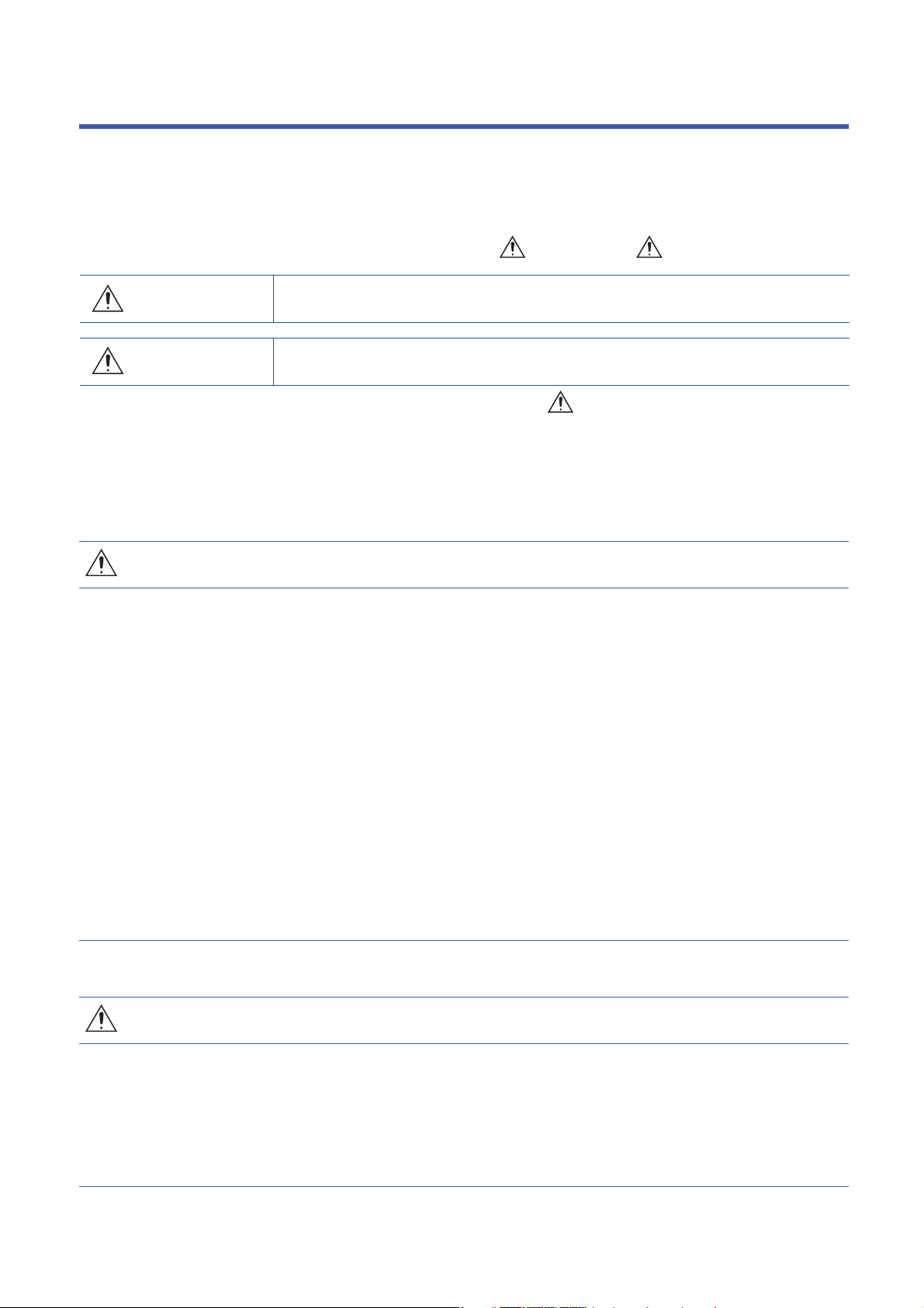
2
(7) (9)(8) (8)
(1)
(6)
(2) (3) (4) (5)
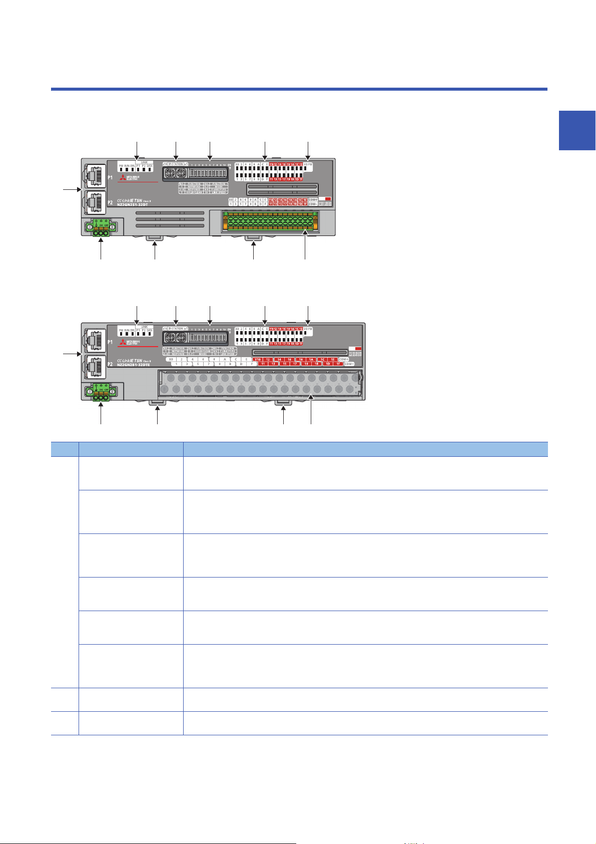
(7) (9)(8) (8)
(1)
(6)
(2) (3) (4) (5)
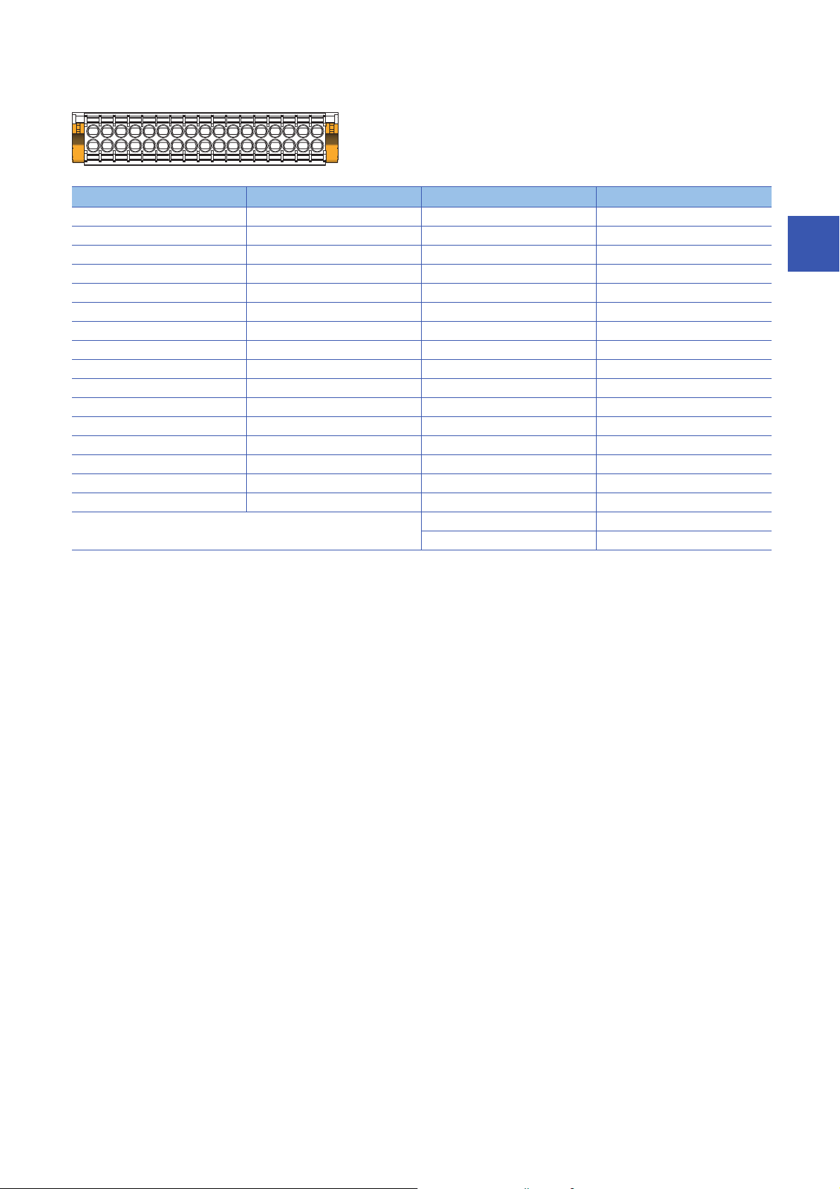
PART NAMES
This section describes part names of the I/O module.
• Spring clamp terminal block type
• Screw terminal block type
2
No. Name Application
(1) PW LED Indicates the power supply status of the I/O module.
RUN LED Indicates the operating status of the I/O module.
ERR. LED Indicates the error status of the I/O module.
P1 LINK LED Indicates the link status for P1.
P2 LINK LED Indicates the link status for P2.
DATA LINK LED
(2) IP address setting switch Sets the fourth octet of the IP address.
(3) Function setting switch Sets functions of the I/O module.
*3
On: Power supply ON
Off: Power supply OFF
On: Operating normally.
Flashing: Operating in unit test mode
Off: A major error has occurred.
On: A moderate error or major error has occurred.
Flashing: A minor error has occurred.
Off: Operating normally.
On: Link-up
Off: Linkdown in progress
On: Link-up
Off: Linkdown in progress
Indicates the data link status of the I/O module.
On: Cyclic transmission being performed
Flashing: Cyclic transmission stopped
Off: Disconnected
Page 58 IP address setting switch setting
Page 60 Function setting switch setting
2 PART NAMES
13
Page 16

No. Name Application
(4) X0 LED to X1F LED Indicates the ON/OFF status of the inputs.
Y0 LED to Y1F LED Indicates the ON/OFF status of the outputs.
(5) I/O PW LED Indicates the status of the power supply from the external power supply.
(6) P1 A port for the connection to CC-Link IE TSN (RJ45 connector)
P2 Same as P1
(7) Terminal block for module
power supply and FG
(8) DIN rail hook A hook to mount an I/O module on a DIN rail
(9) I/O terminal block A terminal block for I/O power supply and I/O signals
On: Input ON
Off: Input OFF
On: Output ON
Off: Output OFF
On: External power supply ON
Off: External power supply OFF
Connect an Ethernet cable. ( Page 67 Wiring of Ethernet Cable)
There are no restrictions on the connection order of the cables for P1 and P2.
A terminal block to connect the module power supply (24VDC) and FG.
*1
*2
*1 The status of actual input signals that are externally input is indicated on the LEDs regardless of the status of the remote input signal.
*2 Output commands from the I/O module are indicated on the LEDs regardless of the status of the external power supply.
*3 "D LINK LED" or "D LINK" may be used as an abbreviation for DATA LINK LED.
I/O module status and LED status
The following table lists the correspondence between the I/O module status and the LED status.
I/O module status LED status
PW LED RUN LED DATA LINK LED ERR. LED
Disconnected On On Off
Data link in operation On On On
Reserved station setting in progress On On Flashing
Data link stop On On Flashing
Network initial setting in progress
Unit test In progress On Flashing Off Off
Normal completion On On Off Off
Abnormal
completion
Error Major error On Off
Moderate error On On
Minor error On On
*2
On On Flashing
On On Off On
*1
*1
*1
*1
*1
*1
*1
*1
On
On
Flashing
*1 Either of On, Flashing, or Off.
*2 If the master station becomes absent during network initial setting, the DATA LINK LED may flash continuously.
2 PART NAMES
14
Page 17
3
SPECIFICATIONS
This chapter describes the specifications of the I/O module.
3.1
Item Specifications
Operating ambient temperature 0 to 55
Storage ambient temperature -25 to 75
Operating ambient humidity 5 to 95%RH, non-condensing
Storage ambient humidity
Vibration resistance Compliant with JIS
Shock resistance Compliant with JIS B 3502 and IEC 61131-2 (147m/, 3 times each in X, Y, and Z directions)
Operating atmosphere No corrosive gases, flammable gases, less conductive dust
Operating altitude
Installation location Inside a control panel
Overvoltage category
Pollution degree
Equipment class Class
*1 Do not use or store the I/O module under pressure higher than the atmospheric pressure of altitude 0m. Doing so may cause
malfunction. When using the I/O module under pressure, please consult your local Mitsubishi representative.
*2 If the environment satisfies the operating ambient temperature, operating ambient humidity and other conditions, the module can be
used even outside the control panel.
*3 This indicates the section of the power supply to which the equipment is assumed to be connected between the public electrical power
distribution network and the machinery within premises.
Category applies to equipment for which electrical power is supplied from fixed facilities. The surge voltage withstand level for the
equipment with the rated voltage of 300V or less is 2500V.
*4 This index indicates the degree to which conductive material is generated in terms of the environment in which the equipment is used.
Pollution degree 2 is when only non-conductive pollution occurs. A temporary conductivity caused by condensing must be expected
occasionally.
General Specifications
B 3502 and IEC
61131-2
*1
*3
*4
0 to 2000m
or less
2 or less
Frequency Constant
Under intermittent
vibration
Under continuous
vibration
*2
acceleration
5 to 8.4Hz 3.5mm 10 times each in X,
8.4 to 150Hz 9.8m/
5 to 8.4Hz 1.75mm
8.4 to 150Hz 4.9m/
Half amplitude Number of sweeps
Y, and Z directions
3
For compliance with the EMC Directive, refer to the following:
Page 125 EMC and Low Voltage Directives
3 SPECIFICATIONS
3.1 General Specifications
15
Page 18

3.2
The following table shows the Ethernet communication specifications for the I/O module.
Item Description
Transmission specifications Data transmission speed 1Gbps
*1 For the maximum segment length (length between hubs), check with the manufacturer of the switching hub to be used.
Ethernet Communication Specifications
Communication mode 1000BASE-T Full-duplex
Interface RJ45 connector (AUTO MDI/MDI-X)
Maximum frame size 1518 bytes
Maximum segment length 100m
Number of cascade
connections
IP version IPv4
1000BASE-T Check with the manufacturer of the switching hub to be used.
*1
16
3 SPECIFICATIONS
3.2 Ethernet Communication Specifications
Page 19

3.3
Performance Specifications
Input module
NZ2GN2S1-32D DC input module
Item NZ2GN2S1-32D
Station type Remote station
Authentication Class Authentication Class B
Number of input points 32 points
Rated input voltage 24VDC (ripple rate: 5% or less) (Allowable voltage range: 20.4 to 28.8VDC)
Rated input current 6.0mA TYP. (for 24VDC)
Maximum number of simultaneous input points 100%
ON voltage/ON current 11VDC or more/4mA or more
OFF voltage/OFF current 5VDC or less/1.5mA or less
Input resistance 3.3kΩ
Input response time OFF → ON 0ms
ON → OFF
Withstand voltage 510VAC for 1 minute between all DC external terminals and ground
Insulation resistance 10MΩ or higher between all DC external terminals and ground (500VDC insulation resistance tester)
Noise immunity
Protection degree IP2X
Wiring method for common 32 points/common (Common terminal: terminal number 33, 34) (1-wire, spring clamp terminal block
External interface Communication part RJ45 connector
Applicable wire size For power supply Stranded wire: 0.3 to 1.5 (22 to 16 AWG), terminal slot size: 2.4mm × 1.5mm
Applicable solderless
terminal
Cyclic transmission RX/RY points 32 points
Module power supply Voltage 24VDC (ripple rate: 5% or less) (Allowable voltage range: 20.4 to 28.8VDC)
Weight 0.20kg
*1 If the input response time is set to "0ms", the actual input response time is 80μs at OFF → ON, and 160μs at ON → OFF.
*2 It is the noise immunity of when the input response time setting value is other than "0ms". Note that the module is easily affected by
noise if "0ms" is set.
*3 Use bar solderless terminals for wiring.
*4 Only one wire can be inserted into a wire insertion opening. Multiple wires cannot be connected to a terminal. Connecting two or more
wires may cause a poor contact.
*2
Module power supply part Terminal block for module power supply and FG (2-piece spring clamp terminal block)
I/O part 2-piece spring clamp terminal block
For I/O Stranded wire: 0.3 to 1.5 (22 to 16 AWG)
*4
Terminal block for module
power supply and FG
Terminal block for input Page 69 Applicable solderless terminal
RWr/RWw points 4 points
Current 110mA or less (24VDC, all points ON)
*1
/0.2ms/1ms/1.5ms/5ms/10ms/20ms/70ms
(Factory default: 1ms)
Noise voltage 500Vp-p, noise width 1μs, noise frequency 25 to 60Hz (DC type noise simulator
condition)
type)
Positive common/negative common shared type
*3
Page 65 Applicable solderless terminal
3
3 SPECIFICATIONS
3.3 Performance Specifications
17
Page 20
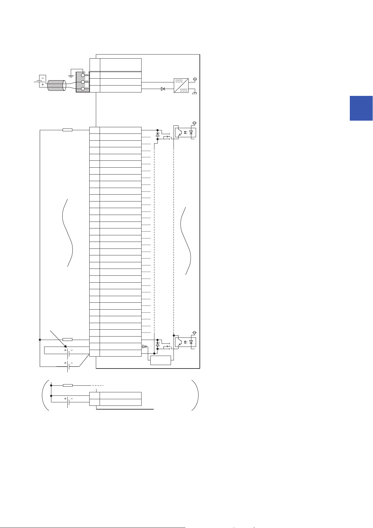
■External wiring
FG
1
2
3
UNIT POWER
CABLE
1
2
3
X01
X12
X23
X34
X45
X56
7
X78
X89
X910
XA11
XB12
XC13
XD14
XE15
XF16
X1017
X1118
X1219
X1320
X1421
X1522
X1623
X1724
X1825
X1926
X1A27
X1B28
X1C29
X1D30
X1E31
X1F32
COM33
COM34
+24V
24G
X6
Signal name
Pin
No.
Non-insulated
Terminal block
for input
*1
Terminal block for module
power supply and FG
*1
Module power
supply
*1 Only one wire can be inserted into a wire insertion opening. Multiple wires cannot be connected to a terminal. Connecting two or more
wires may cause a poor contact.
3 SPECIFICATIONS
18
3.3 Performance Specifications
Page 21

■Terminal block for input
33312927252321191715131197531
343230282624222018161412108642
Terminal number Signal name Terminal number Signal name
1X017X10
2X118X11
3X219X12
4X320X13
5X421X14
6X522X15
7X623X16
8X724X17
9X825X18
10 X9 26 X19
11 XA 27 X1 A
12 XB 28 X1B
13 XC 29 X1C
14 XD 30 X1D
15 XE 31 X1E
16 XF 32 X1F
33 COM
34 COM
3
3.3 Performance Specifications
3 SPECIFICATIONS
19
Page 22

NZ2GN2B1-32D DC input module
Item NZ2GN2B1-32D
Station type Remote station
Authentication Class Authentication Class B
Number of input points 32 points
Rated input voltage 24VDC (ripple rate: 5% or less) (Allowable voltage range: 20.4 to 28.8VDC)
Rated input current 6.0mA TYP. (for 24VDC)
Maximum number of simultaneous input points 100%
ON voltage/ON current 11VDC or more/4mA or more
OFF voltage/OFF current 5VDC or less/1.5mA or less
Input resistance 3.3kΩ
Input response time OFF → ON 0ms
ON → OFF
Withstand voltage 510VAC for 1 minute between all DC external terminals and ground
Insulation resistance 10MΩ or higher between all DC external terminals and ground (500VDC insulation resistance tester)
Noise immunity
Protection degree IP2X
Wiring method for common 32 points/common (Common terminal: terminal number 33, 34) (1-wire, screw terminal block type)
External interface Communication part RJ45 connector
Applicable wire size For power supply Stranded wire: 0.3 to 1.5 (22 to 16 AWG), terminal slot size: 2.4mm × 1.5mm
Applicable solderless
terminal
Cyclic transmission RX/RY points 32 points
Module power supply Voltage 24VDC (ripple rate: 5% or less) (Allowable voltage range: 20.4 to 28.8VDC)
Weight 0.31kg
*2
Module power supply part Terminal block for module power supply and FG (2-piece spring clamp terminal block)
I/O part 34-point two-piece terminal block
For I/O Stranded wire: 0.3 to 2.0 (22 to 14 AWG)
Terminal block for module
power supply and FG
Terminal block for input Page 72 Applicable solderless terminal
RWr/RWw points 4 points
Current 110mA or less (24VDC, all points ON)
*4
*1 If the input response time is set to "0ms", the actual input response time is 80μs at OFF → ON, and 160μs at ON → OFF.
*2 It is the noise immunity of when the input response time setting value is other than "0ms". Note that the module is easily affected by
noise if "0ms" is set.
*3 Use bar solderless terminals for wiring.
*4 Only one wire can be inserted into a wire insertion opening for the terminal block for module power supply and FG. Multiple wires cannot
be connected to a terminal. Connecting two or more wires may cause a poor contact.
*1
/0.2ms/1ms/1.5ms/5ms/10ms/20ms/70ms
(Factory default: 1ms)
Noise voltage 500Vp-p, noise width 1μs, noise frequency 25 to 60Hz (DC type noise simulator
condition)
Positive common/negative common shared type
Tightening torque range for terminal screw (M3 × 5.2 screw): 0.43 to 0.57N⋅m
Tightening torque range for terminal block mounting screw (M3.5 screw): 0.68 to 0.92N⋅m
*3
Page 65 Applicable solderless terminal
20
3 SPECIFICATIONS
3.3 Performance Specifications
Page 23
■External wiring
FG
1
2
3
UNIT POWER
CABLE
1
2
3
X01
X12
X23
X34
X45
X56
7
X78
X89
X910
XA11
XB12
XC13
XD14
XE15
XF16
X1017
X1118
X1219
X1320
X1421
X1522
X1623
X1724
X1825
X1926
X1A27
X1B28
X1C29
X1D30
X1E31
X1F32
COM33
COM34
+24V
24G
X6
Signal name
Pin
No.
Non-insulated
Terminal block
for input
Terminal block for module
power supply and FG
*1
Module power
supply
3
*1 Only one wire can be inserted into a wire insertion opening for the terminal block for module power supply and FG. Multiple wires cannot
be connected to a terminal. Connecting two or more wires may cause a poor contact.
3 SPECIFICATIONS
3.3 Performance Specifications
21
Page 24

■Terminal block for input
33312927252321191715131197531
343230282624222018161412108642
Terminal number Signal name Terminal number Signal name
1X017X10
2X118X11
3X219X12
4X320X13
5X421X14
6X522X15
7X623X16
8X724X17
9X825X18
10 X9 26 X19
11 XA 27 X1 A
12 XB 28 X1B
13 XC 29 X1C
14 XD 30 X1D
15 XE 31 X1E
16 XF 32 X1F
33 COM
34 COM
22
3 SPECIFICATIONS
3.3 Performance Specifications
Page 25

Output module
NZ2GN2S1-32T transistor output module
Item NZ2GN2S1-32T
Station type Remote station
Authentication Class Authentication Class B
Number of output points 32 points
Rated load voltage 12/24VDC (ripple rate: 5% or less) (Allowable voltage range: 10.2 to 28.8VDC)
Max. load current 0.5A/point, 5A/common
Maximum inrush current Current is limited by the overload protection function.
Leakage current at OFF 0.1mA or less
Max. voltage drop at ON 0.3VDC (TYP.) 0.5A, 0.6VDC (MAX.) 0.5A
Output response time OFF → ON 0.1ms or less
ON → OFF 0.8ms or less (resistive load)
Surge suppressor Zener diode
External power supply
for output part
Withstand voltage 510VAC for 1 minute between all DC external terminals and ground
Insulation resistance 10MΩ or higher between all DC external terminals and ground (500VDC insulation resistance tester)
Noise immunity Noise voltage 500Vp-p, noise width 1μs, noise frequency 25 to 60Hz (DC type noise simulator
Protection degree IP2X
Wiring method for common 32 points/common (Common terminal: terminal number 34) (1-wire, spring clamp terminal block type)
Protection function Overload protection
External interface Communication part RJ45 connector
Applicable wire size For power supply Stranded wire: 0.3 to 1.5 (22 to 16 AWG), terminal slot size: 2.4mm × 1.5mm
Applicable solderless
*2
terminal
Cyclic transmission RX/RY points 32 points
Module power supply Voltage 24VDC (ripple rate: 5% or less) (Allowable voltage range: 20.4 to 28.8VDC)
Weight 0.18kg
*1 Use bar solderless terminals for wiring.
*2 Only one wire can be inserted into a wire insertion opening. Multiple wires cannot be connected to a terminal. Connecting two or more
wires may cause a poor contact.
Voltage 12/24VDC (ripple rate: 5% or less) (Allowable voltage range: 10.2 to 28.8VDC)
Current 40mA or less (TYP. 24VDC per common) External load current is not included.
condition)
Sink type
Limited current when detecting overcurrent: 1.5 to 3.5A/point
function
Overheat protection
function
Module power supply
part
I/O part 2-piece spring clamp terminal block
For I/O Stranded wire: 0.3 to 1.5 (22 to 16 AWG)
Terminal block for
module power supply
and FG
Terminal block for output Page 69 Applicable solderless terminal
RWr/RWw poin ts 4 points
Current 120mA or less (24VDC, all points ON)
Activated to each point.
Activated to each point.
Terminal block for module power supply and FG (2-piece spring clamp terminal block)
Page 65 Applicable solderless terminal
*1
3
3 SPECIFICATIONS
3.3 Performance Specifications
23
Page 26
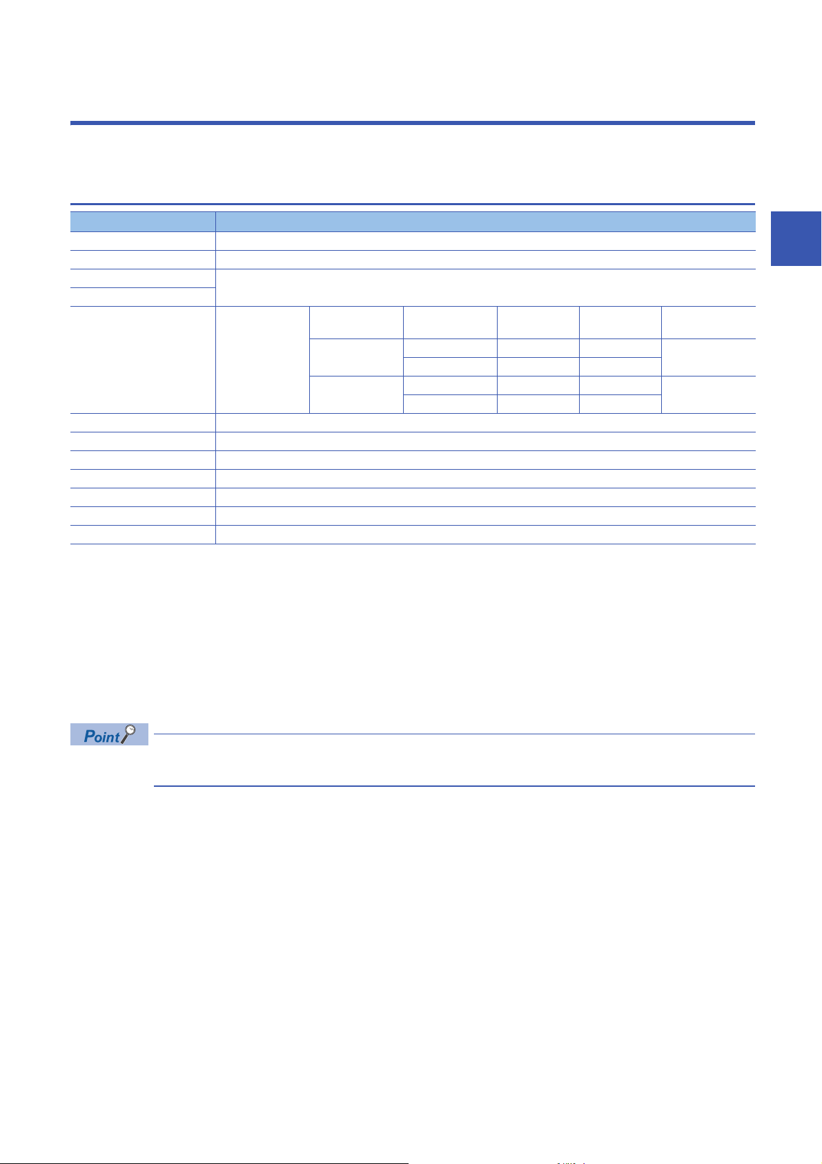
■External wiring
YF
Y0
Y1
Y2
Y3
Y4
Y5
Y6
Y7
Y8
Y9
YA
YB
YC
YD
YE
Y10
Y11
Y12
Y13
Y14
Y15
Y16
Y17
Y18
Y19
Y1A
Y1B
Y1C
Y1D
Y1E
Y1F
CTL+
COM-
1
2
3
4
5
6
7
8
9
10
11
12
13
14
15
16
17
18
19
20
21
22
23
24
25
26
27
28
29
30
31
32
33
34
33
34
CTL+
COM-
FG
1
2
3
UNIT POWER
CABLE
1
2
3
+24V
24G
Terminal block
for output
*1
Load
Load
Load
Load power
supply
External power supply for the output part
and load power supply (common)
External power supply
for the output part
Signal name
Pin
No.
Non-insulated
Terminal block for module
power supply and FG
*1
Module power
supply
Constantvoltage circuit
*1 Only one wire can be inserted into a wire insertion opening. Multiple wires cannot be connected to a terminal. Connecting two or more
wires may cause a poor contact.
24
3 SPECIFICATIONS
3.3 Performance Specifications
Page 27
■Terminal block for output
33312927252321191715131197531
343230282624222018161412108642
Terminal number Signal name Terminal number Signal name
1Y017Y10
2Y118Y11
3Y219Y12
4Y320Y13
5Y421Y14
6Y522Y15
7Y623Y16
8Y724Y17
9Y825Y18
10 Y9 26 Y19
11 YA 27 Y1 A
12 YB 28 Y1B
13 YC 29 Y1C
14 YD 30 Y1D
15 YE 31 Y1E
16 YF 32 Y1F
33 CTL+
34 COM-
3
3.3 Performance Specifications
3 SPECIFICATIONS
25
Page 28

NZ2GN2B1-32T transistor output module
Item NZ2GN2B1-32T
Station type Remote station
Authentication Class Authentication Class B
Number of output points 32 points
Rated load voltage 12/24VDC (ripple rate: 5% or less) (Allowable voltage range: 10.2 to 28.8VDC)
Max. load current 0.5A/point, 5A/common
Maximum inrush current Current is limited by the overload protection function.
Leakage current at OFF 0.1mA or less
Max. voltage drop at ON 0.3VDC (TYP.) 0.5A, 0.6VDC (MAX.) 0.5A
Output response time OFF → ON 0.1ms or less
ON → OFF 0.8ms or less (resistive load)
Surge suppressor Zener diode
External power supply for
output part
Withstand voltage 510VAC for 1 minute between all DC external terminals and ground
Insulation resistance 10MΩ or higher between all DC external terminals and ground (500VDC insulation resistance tester)
Noise immunity Noise voltage 500Vp-p, noise width 1μs, noise frequency 25 to 60Hz (DC type noise simulator
Protection degree IP2X
Wiring method for common 32 points/common (Common terminal: terminal number 34) (1-wire, screw terminal block type)
Protection function Overload protection
External interface Communication part RJ45 connector
Applicable wire size For power supply Stranded wire: 0.3 to 1.5 (22 to 16 AWG), terminal slot size: 2.4mm × 1.5mm
Applicable solderless
terminal
Cyclic transmission RX/RY points 32 points
Module power supply Voltage 24VDC (ripple rate: 5% or less) (Allowable voltage range: 20.4 to 28.8VDC)
Weight 0.29kg
*1 Use bar solderless terminals for wiring.
*2 Only one wire can be inserted into a wire insertion opening for the terminal block for module power supply and FG. Multiple wires cannot
be connected to a terminal. Connecting two or more wires may cause a poor contact.
Voltage 12/24VDC (ripple rate: 5% or less) (Allowable voltage range: 10.2 to 28.8VDC)
Current 40mA or less (TYP. 24VDC per common) External load current is not included.
condition)
Sink type
function
Overheat protection
function
Module power supply part Terminal block for module power supply and FG (2-piece spring clamp terminal block)
I/O part 34-point two-piece terminal block
For I/O Stranded wire: 0.3 to 2.0 (22 to 14 AWG)
Terminal block for module
power supply and FG
Terminal block for output Page 72 Applicable solderless terminal
RWr/RWw points 4 points
Current 120mA or less (24VDC, all points ON)
Limited current when detecting overcurrent: 1.5 to 3.5A/point
Activated to each point.
Activated to each point.
Tightening torque range for terminal screw (M3 × 5.2 screw): 0.43 to 0.57N⋅m
Tightening torque range for terminal block mounting screw (M3.5 screw): 0.68 to 0.92N⋅m
Page 65 Applicable solderless terminal
*2
*1
26
3 SPECIFICATIONS
3.3 Performance Specifications
Page 29
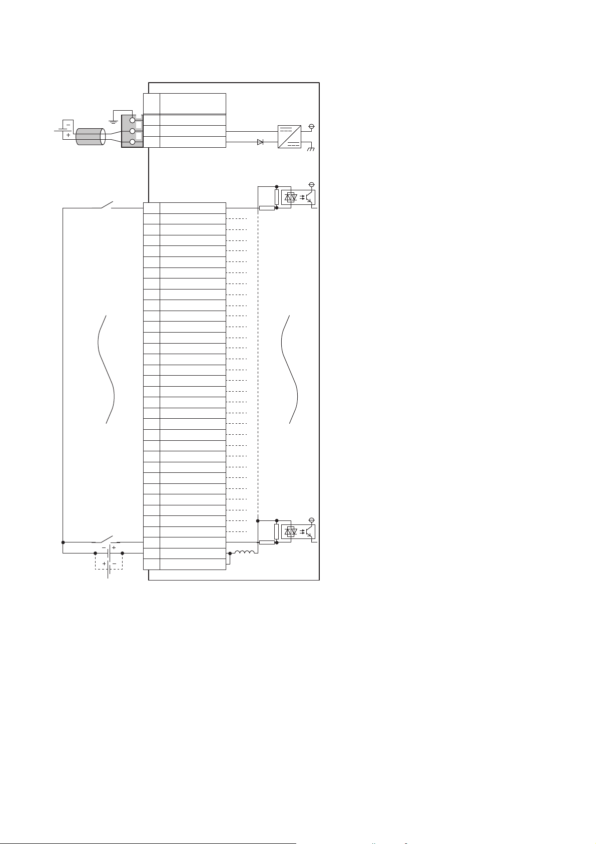
■External wiring
YF
Y0
Y1
Y2
Y3
Y4
Y5
Y6
Y7
Y8
Y9
YA
YB
YC
YD
YE
Y10
Y11
Y12
Y13
Y14
Y15
Y16
Y17
Y18
Y19
Y1A
Y1B
Y1C
Y1D
Y1E
Y1F
CTL+
COM-
1
2
3
4
5
6
7
8
9
10
11
12
13
14
15
16
17
18
19
20
21
22
23
24
25
26
27
28
29
30
31
32
33
34
33
34
CTL+
COM-
FG
1
2
3
UNIT POWER
CABLE
1
2
3
+24V
24G
Terminal block
for output
Load
Load
Load
Load power
supply
External power supply for the output part
and load power supply (common)
External power supply
for the output part
Signal name
Pin
No.
Non-insulated
Terminal block for module
power supply and FG
*1
Module power
supply
Constantvoltage circuit
3
*1 Only one wire can be inserted into a wire insertion opening for the terminal block for module power supply and FG. Multiple wires cannot
be connected to a terminal. Connecting two or more wires may cause a poor contact.
3 SPECIFICATIONS
3.3 Performance Specifications
27
Page 30

■Terminal block for output
33312927252321191715131197531
343230282624222018161412108642
Terminal number Signal name Terminal number Signal name
1Y017Y10
2Y118Y11
3Y219Y12
4Y320Y13
5Y421Y14
6Y522Y15
7Y623Y16
8Y724Y17
9Y825Y18
10 Y9 26 Y19
11 YA 27 Y1 A
12 YB 28 Y1B
13 YC 29 Y1C
14 YD 30 Y1D
15 YE 31 Y1E
16 YF 32 Y1F
33 CTL+
34 COM-
28
3 SPECIFICATIONS
3.3 Performance Specifications
Page 31

NZ2GN2S1-32TE transistor output module
Item NZ2GN2S1-32TE
Station type Remote station
Authentication Class Authentication Class B
Number of output points 32 points
Rated load voltage 12/24VDC (ripple rate: 5% or less) (Allowable voltage range: 10.2 to 28.8VDC)
Max. load current 0.5A/point, 5A/common
Maximum inrush current Current is limited by the overload protection function.
Leakage current at OFF 0.1mA or less
Max. voltage drop at ON 0.5VDC (TYP.) 0.5A, 0.8VDC (MAX.) 0.5A
Output response time OFF → ON 0.5ms or less
ON → OFF 1.0ms or less (resistive load)
Surge suppressor Zener diode
External power supply for
output part
Withstand voltage 510VAC for 1 minute between all DC external terminals and ground
Insulation resistance 10MΩ or higher between all DC external terminals and ground (500VDC insulation resistance tester)
Noise immunity Noise voltage 500Vp-p, noise width 1μs, noise frequency 25 to 60Hz (DC type noise simulator
Protection degree IP2X
Wiring method for common 32 points/common (Common terminal: terminal number 33) (1-wire, spring clamp terminal block type)
Protection function Overload protection
External interface Communication part RJ45 connector
Applicable wire size For power supply Stranded wire: 0.3 to 1.5 (22 to 16 AWG), terminal slot size: 2.4mm × 1.5mm
Applicable solderless
*2
terminal
Cyclic transmission RX/RY points 32 points
Module power supply Voltage 24VDC (ripple rate: 5% or less) (Allowable voltage range: 20.4 to 28.8VDC)
Weight 0.18kg
*1 Use bar solderless terminals for wiring.
*2 Only one wire can be inserted into a wire insertion opening. Multiple wires cannot be connected to a terminal. Connecting two or more
wires may cause a poor contact.
Voltage 12/24VDC (ripple rate: 5% or less) (Allowable voltage range: 10.2 to 28.8VDC)
Current 80mA or less (TYP. 24VDC per common) External load current is not included.
condition)
Source type
function
Overheat protection
function
Module power supply part Terminal block for module power supply and FG (2-piece spring clamp terminal block)
I/O part 2-piece spring clamp terminal block
For I/O Stranded wire: 0.3 to 1.5 (22 to 16 AWG)
Terminal block for module
power supply and FG
Terminal block for output Page 69 Applicable solderless terminal
RWr/RWw points 4 points
Current 120mA or less (24VDC, all points ON)
Limited current when detecting overcurrent: 1.5A or more/point
Activated to each point.
Activated to each point.
*1
Page 65 Applicable solderless terminal
3
3 SPECIFICATIONS
3.3 Performance Specifications
29
Page 32

■External wiring
1
2
3
4
5
6
7
8
9
10
11
12
13
14
15
16
17
18
19
20
21
22
23
24
25
26
27
28
29
30
31
32
33
34
Y0
Y1
Y2
Y3
Y4
Y5
Y6
Y7
Y8
Y9
YF
YA
YB
YC
YD
YE
Y10
Y11
Y12
Y13
Y14
Y15
Y16
Y17
Y18
Y19
Y1A
Y1B
Y1C
Y1D
Y1E
Y1F
COM+
CTL-
FG
1
2
3
UNIT POWER
CABLE
1
2
3
+24V
24G
Terminal block
for output
*1
Load
Load
External power supply for the output
part and load power supply (common)
Signal name
Pin
No.
Non-insulated
Terminal block for module
power supply and FG
*1
Module power
supply
Constantvoltage circuit
*1 Only one wire can be inserted into a wire insertion opening. Multiple wires cannot be connected to a terminal. Connecting two or more
30
wires may cause a poor contact.
3 SPECIFICATIONS
3.3 Performance Specifications
Page 33

■Terminal block for output
33312927252321191715131197531
343230282624222018161412108642
Terminal number Signal name Terminal number Signal name
1Y017Y10
2Y118Y11
3Y219Y12
4Y320Y13
5Y421Y14
6Y522Y15
7Y623Y16
8Y724Y17
9Y825Y18
10 Y9 26 Y19
11 YA 27 Y1 A
12 YB 28 Y1B
13 YC 29 Y1C
14 YD 30 Y1D
15 YE 31 Y1E
16 YF 32 Y1F
33 COM+
34 CTL-
3
3.3 Performance Specifications
3 SPECIFICATIONS
31
Page 34

NZ2GN2B1-32TE transistor output module
Item NZ2GN2B1-32TE
Station type Remote station
Authentication Class Authentication Class B
Number of output points 32 points
Rated load voltage 12/24VDC (ripple rate: 5% or less) (Allowable voltage range: 10.2 to 28.8VDC)
Max. load current 0.5A/point, 5A/common
Maximum inrush current Current is limited by the overload protection function.
Leakage current at OFF 0.1mA or less
Max. voltage drop at ON 0.5VDC (TYP.) 0.5A, 0.8VDC (MAX.) 0.5A
Output response time OFF → ON 0.5ms or less
ON → OFF 1.0ms or less (resistive load)
Surge suppressor Zener diode
External power supply for
output part
Withstand voltage 510VAC for 1 minute between all DC external terminals and ground
Insulation resistance 10MΩ or higher between all DC external terminals and ground (500VDC insulation resistance tester)
Noise immunity Noise voltage 500Vp-p, noise width 1μs, noise frequency 25 to 60Hz (DC type noise simulator
Protection degree IP2X
Wiring method for common 32 points/common (Common terminal: terminal number 33) (1-wire, screw terminal block type)
Protection function Overload protection
External interface Communication part RJ45 connector
Applicable wire size For power supply Stranded wire: 0.3 to 1.5 (22 to 16 AWG), terminal slot size: 2.4mm × 1.5mm
Applicable solderless
terminal
Cyclic transmission RX/RY points 32 points
Module power supply Voltage 24VDC (ripple rate: 5% or less) (Allowable voltage range: 20.4 to 28.8VDC)
Weight 0.29kg
*1 Use bar solderless terminals for wiring.
*2 Only one wire can be inserted into a wire insertion opening for the terminal block for module power supply and FG. Multiple wires cannot
be connected to a terminal. Connecting two or more wires may cause a poor contact.
Voltage 12/24VDC (ripple rate: 5% or less) (Allowable voltage range: 10.2 to 28.8VDC)
Current 80mA or less (TYP. 24VDC per common) External load current is not included.
condition)
Source type
function
Overheat protection
function
Module power supply part Terminal block for module power supply and FG (2-piece spring clamp terminal block)
I/O part 34-point two-piece terminal block
For I/O Stranded wire: 0.3 to 2.0 (22 to 14 AWG)
Terminal block for module
power supply and FG
Terminal block for output Page 72 Applicable solderless terminal
RWr/RWw points 4 points
Current 120mA or less (24VDC, all points ON)
Limited current when detecting overcurrent: 1.5A or more/point
Activated to each point.
Activated to each point.
Tightening torque range for terminal screw (M3 × 5.2 screw): 0.43 to 0.57N⋅m
Tightening torque range for terminal block mounting screw (M3.5 screw): 0.68 to 0.92N⋅m
Page 65 Applicable solderless terminal
*2
*1
32
3 SPECIFICATIONS
3.3 Performance Specifications
Page 35

■External wiring
1
2
3
4
5
6
7
8
9
10
11
12
13
14
15
16
17
18
19
20
21
22
23
24
25
26
27
28
29
30
31
32
33
34
Y0
Y1
Y2
Y3
Y4
Y5
Y6
Y7
Y8
Y9
YF
YA
YB
YC
YD
YE
Y10
Y11
Y12
Y13
Y14
Y15
Y16
Y17
Y18
Y19
Y1A
Y1B
Y1C
Y1D
Y1E
Y1F
COM+
CTL-
FG
1
2
3
UNIT POWER
CABLE
1
2
3
+24V
24G
Terminal block
for output
Load
Load
External power supply for the output
part and load power supply (common)
Signal name
Pin
No.
Non-insulated
Terminal block for module
power supply and FG
*1
Module power
supply
Constantvoltage circuit
3
*1 Only one wire can be inserted into a wire insertion opening for the terminal block for module power supply and FG. Multiple wires cannot
be connected to a terminal. Connecting two or more wires may cause a poor contact.
3 SPECIFICATIONS
3.3 Performance Specifications
33
Page 36

■Terminal block for output
33312927252321191715131197531
343230282624222018161412108642
Terminal number Signal name Terminal number Signal name
1Y017Y10
2Y118Y11
3Y219Y12
4Y320Y13
5Y421Y14
6Y522Y15
7Y623Y16
8Y724Y17
9Y825Y18
10 Y9 26 Y19
11 YA 27 Y1 A
12 YB 28 Y1B
13 YC 29 Y1C
14 YD 30 Y1D
15 YE 31 Y1E
16 YF 32 Y1F
33 COM+
34 CTL-
34
3 SPECIFICATIONS
3.3 Performance Specifications
Page 37

I/O combined module
NZ2GN2S1-32DT DC input/transistor output module
Item NZ2GN2S1-32DT
Input specifications
Number of input points 16 points
Rated input voltage 24VDC (ripple rate: 5% or less) (Allowable voltage range: 20.4 to 28.8VDC)
Rated input current 6.0mA TYP. (for 24VDC)
Maximum number of simultaneous input points 100%
ON voltage/ON current 11VDC or more/4mA or more
OFF voltage/OFF current 5VDC or less/1.5mA or less
Input resistance 3.3kΩ
Input response time OFF → ON 0ms
ON → OFF
Wiring method for common 16 points/common (Common terminal: terminal number 33) (1-wire, spring clamp terminal block type)
Output specifications
Number of output points 16 points
Rated load voltage 24VDC (ripple rate: 5% or less) (Allowable voltage range: 20.4 to 28.8VDC)
Max. load current 0.5A/point, 4A/common
Maximum inrush current Current is limited by the overload protection function.
Leakage current at OFF 0.1mA or less
Max. voltage drop at ON 0.3VDC (TYP.) 0.5A, 0.6VDC (MAX.) 0.5A
Output response time OFF → ON 0.1ms or less
ON → OFF 0.8ms or less (resistive load)
Surge suppressor Zener diode
External power supply for
output part
Protection function Overload protection
Wiring method for common 16 points/common (Common terminal: terminal number 34) (1-wire, spring clamp terminal block type)
Common specifications
Station type Remote station
Authentication Class Authentication Class B
Withstand voltage 510VAC for 1 minute between all DC external terminals and ground
Insulation resistance 10MΩ or higher between all DC external terminals and ground (500VDC insulation resistance tester)
Noise immunity
Protection degree IP2X
External interface Communication part RJ45 connector
Applicable wire size For power supply Stranded wire: 0.3 to 1.5 (22 to 16 AWG), terminal slot size: 2.4mm × 1.5mm
Applicable solderless
terminal
Cyclic transmission RX/RY points 32 points
Module power supply Voltage 24VDC (ripple rate: 5% or less) (Allowable voltage range: 20.4 to 28.8VDC)
*2
*4
Voltage 24VDC (ripple rate: 5% or less) (Allowable voltage range: 20.4 to 28.8VDC)
Current 25mA or less (TYP. 24VDC per common) External load current is not included.
function
Overheat protection
function
Module power supply part Terminal block for module power supply and FG (2-piece spring clamp terminal block)
I/O part 2-piece spring clamp terminal block
For I/O Stranded wire: 0.3 to 1.5 (22 to 16 AWG)
Terminal block for module
power supply and FG
I/O terminal block Page 69 Applicable solderless terminal
RWr/RWw points 4 points
Current 110mA or less (24VDC, all points ON)
*1
/0.2ms/1ms/1.5ms/5ms/10ms/20ms/70ms
(Factory default: 1ms)
Positive common type
Limited current when detecting overcurrent: 1.5 to 3.5A/point
Activated to each point.
Activated to each point.
Sink type
Noise voltage 500Vp-p, noise width 1μs, noise frequency 25 to 60Hz (DC type noise simulator
condition)
*3
Page 65 Applicable solderless terminal
3
3 SPECIFICATIONS
3.3 Performance Specifications
35
Page 38

Item NZ2GN2S1-32DT
Weight 0.20kg
*1 If the input response time is set to "0ms", the actual input response time is 80μs at OFF → ON, and 160μs at ON → OFF.
*2 It is the noise immunity of when the input response time setting value is other than "0ms". Note that the module is easily affected by
noise if "0ms" is set.
*3 Use bar solderless terminals for wiring.
*4 Only one wire can be inserted into a wire insertion opening. Multiple wires cannot be connected to a terminal. Connecting two or more
wires may cause a poor contact.
36
3 SPECIFICATIONS
3.3 Performance Specifications
Page 39

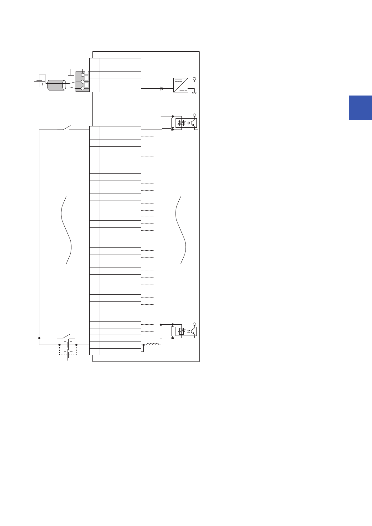
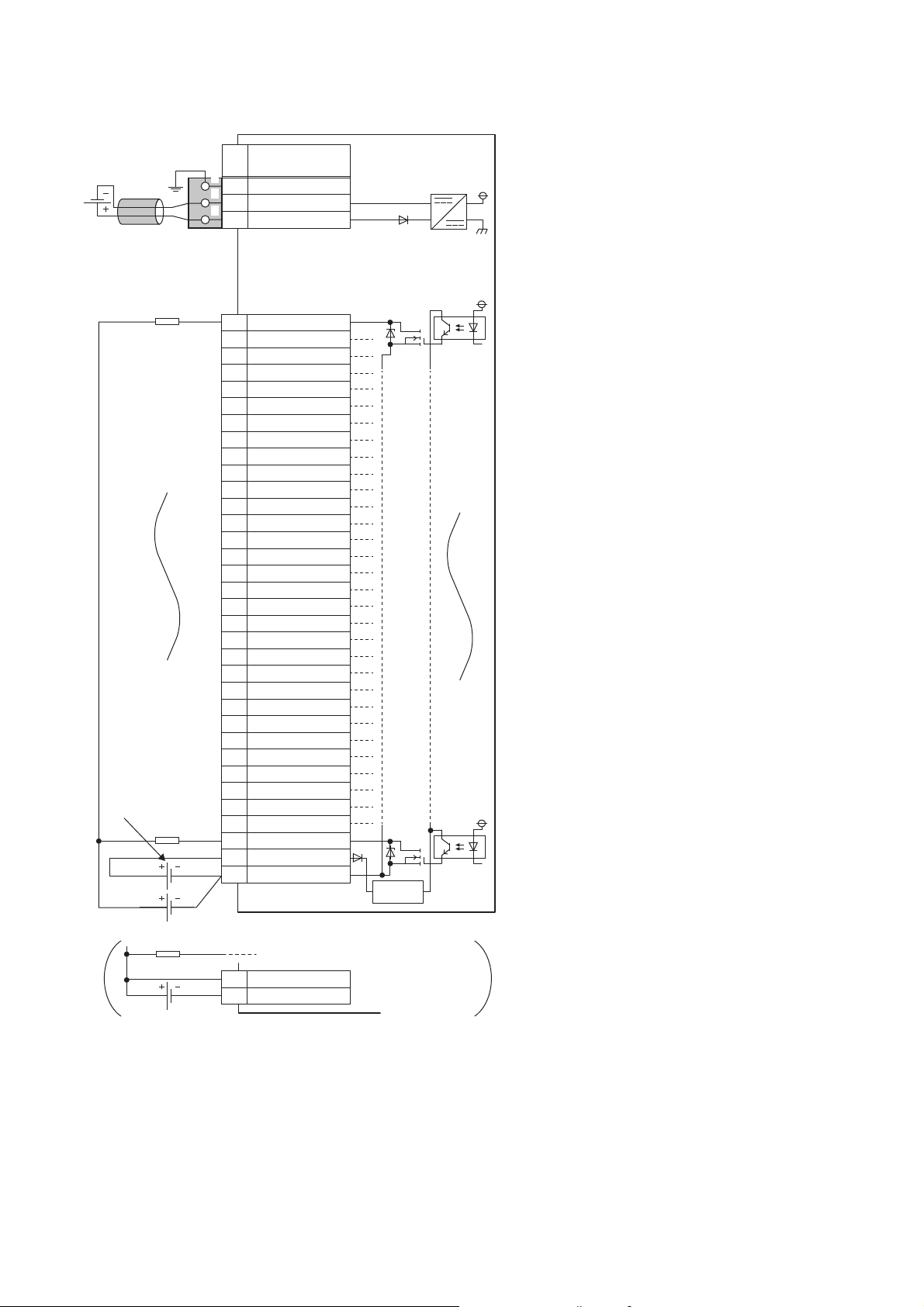
■External wiring
1
2
3
4
5
6
7
8
9
10
11
12
13
14
15
16
17
18
19
20
21
22
23
24
25
26
27
28
29
30
31
32
33
34
33
34
COM+
COM-
X0
X1
X2
X3
X4
X5
X7
X8
X9
XA
XB
XC
XD
XE
XF
X6
Y1F
Y10
Y11
Y12
Y13
Y14
Y15
Y16
Y17
Y18
Y19
Y1A
Y1B
Y1C
Y1D
Y1E
COM+
COM-
FG
1
2
3
UNIT POWER
CABLE
1
2
3
+24V
24G
I/O terminal
block
*1
Load
Load
Load
External power supply for the output part
and load power supply (common)
External power supply
for the output part
Load power
supply
Signal name
Non-insulated
Terminal block for module
power supply and FG
*1
Module power
supply
Pin
No.
Constantvoltage circuit
3
*1 Only one wire can be inserted into a wire insertion opening. Multiple wires cannot be connected to a terminal. Connecting two or more
wires may cause a poor contact.
3 SPECIFICATIONS
3.3 Performance Specifications
37
Page 40

■I/O terminal block
33312927252321191715131197531
343230282624222018161412108642
Terminal number Signal name Terminal number Signal name
1X017Y10
2X118Y11
3X219Y12
4X320Y13
5X421Y14
6X522Y15
7X623Y16
8X724Y17
9X825Y18
10 X9 26 Y19
11 XA 27 Y1 A
12 XB 28 Y1B
13 XC 29 Y1C
14 XD 30 Y1D
15 XE 31 Y1E
16 XF 32 Y1F
33 COM+
34 COM-
38
3 SPECIFICATIONS
3.3 Performance Specifications
Page 41

NZ2GN2B1-32DT DC input/transistor output module
Item NZ2GN2B1-32DT
Input specifications
Number of input points 16 points
Rated input voltage 24VDC (ripple rate: 5% or less) (Allowable voltage range: 20.4 to 28.8VDC)
Rated input current 6.0mA TYP. (for 24VDC)
Maximum number of simultaneous input points 100%
ON voltage/ON current 11VDC or more/4mA or more
OFF voltage/OFF current 5VDC or less/1.5mA or less
Input resistance 3.3kΩ
Input response time OFF → ON 0ms
ON → OFF
Wiring method for common 16 points/common (Common terminal: terminal number 33) (1-wire, screw terminal block type)
Output specifications
Number of output points 16 points
Rated load voltage 24VDC (ripple rate: 5% or less) (Allowable voltage range: 20.4 to 28.8VDC)
Max. load current 0.5A/point, 4A/common
Maximum inrush current Current is limited by the overload protection function.
Leakage current at OFF 0.1mA or less
Max. voltage drop at ON 0.3VDC (TYP.) 0.5A, 0.6VDC (MAX.) 0.5A
Output response time OFF → ON 0.1ms or less
ON → OFF 0.8ms or less (resistive load)
Surge suppressor Zener diode
External power supply for
output part
Protection function Overload protection
Wiring method for common 16 points/common (Common terminal: terminal number 34) (1-wire, screw terminal block type)
Common specifications
Station type Remote station
Authentication Class Authentication Class B
Withstand voltage 510VAC for 1 minute between all DC external terminals and ground
Insulation resistance 10MΩ or higher between all DC external terminals and ground (500VDC insulation resistance tester)
Noise immunity
Protection degree IP2X
External interface Communication part RJ45 connector
Applicable wire size For power supply Stranded wire: 0.3 to 1.5 (22 to 16 AWG), terminal slot size: 2.4mm × 1.5mm
Applicable solderless
terminal
Cyclic transmission RX/RY points 32 points
Module power supply Voltage 24VDC (ripple rate: 5% or less) (Allowable voltage range: 20.4 to 28.8VDC)
Weight 0.31kg
*2
Voltage 24VDC (ripple rate: 5% or less) (Allowable voltage range: 20.4 to 28.8VDC)
Current 25mA or less (TYP. 24VDC per common) External load current is not included.
function
Overheat protection
function
Module power supply part Terminal block for module power supply and FG (2-piece spring clamp terminal block)
I/O part 34-point two-piece terminal block
For I/O Stranded wire: 0.3 to 2.0 (22 to 14 AWG)
Terminal block for module
power supply and FG
I/O terminal block Page 72 Applicable solderless terminal
RWr/RWw points 4 points
Current 110mA or less (24VDC, all points ON)
*4
*1
/0.2ms/1ms/1.5ms/5ms/10ms/20ms/70ms
(Factory default: 1ms)
Positive common type
Limited current when detecting overcurrent: 1.5 to 3.5A/point
Activated to each point.
Activated to each point.
Sink type
Noise voltage 500Vp-p, noise width 1μs, noise frequency 25 to 60Hz (DC type noise simulator
condition)
Tightening torque range for terminal screw (M3 × 5.2 screw): 0.43 to 0.57N⋅m
Tightening torque range for terminal block mounting screw (M3.5 screw): 0.68 to 0.92N⋅m
*3
Page 65 Applicable solderless terminal
3
3 SPECIFICATIONS
3.3 Performance Specifications
39
Page 42

*1 If the input response time is set to "0ms", the actual input response time is 80μs at OFF → ON, and 160μs at ON → OFF.
*2 It is the noise immunity of when the input response time setting value is other than "0ms". Note that the module is easily affected by
noise if "0ms" is set.
*3 Use bar solderless terminals for wiring.
*4 Only one wire can be inserted into a wire insertion opening for the terminal block for module power supply and FG. Multiple wires cannot
be connected to a terminal. Connecting two or more wires may cause a poor contact.
40
3 SPECIFICATIONS
3.3 Performance Specifications
Page 43

■External wiring
1
2
3
4
5
6
7
8
9
10
11
12
13
14
15
16
17
18
19
20
21
22
23
24
25
26
27
28
29
30
31
32
33
34
33
34
COM+
COM-
X0
X1
X2
X3
X4
X5
X7
X8
X9
XA
XB
XC
XD
XE
XF
X6
Y1F
Y10
Y11
Y12
Y13
Y14
Y15
Y16
Y17
Y18
Y19
Y1A
Y1B
Y1C
Y1D
Y1E
COM+
COM-
FG
1
2
3
UNIT POWER
CABLE
1
2
3
+24V
24G
I/O terminal
block
Load
Load
Load
External power supply for the output part
and load power supply (common)
External power supply
for the output part
Load power
supply
Signal name
Non-insulated
Terminal block for module
power supply and FG
*1
Module power
supply
Pin
No.
Constantvoltage circuit
3
*1 Only one wire can be inserted into a wire insertion opening for the terminal block for module power supply and FG. Multiple wires cannot
be connected to a terminal. Connecting two or more wires may cause a poor contact.
3 SPECIFICATIONS
3.3 Performance Specifications
41
Page 44

■I/O terminal block
33312927252321191715131197531
343230282624222018161412108642
Terminal number Signal name Terminal number Signal name
1X017Y10
2X118Y11
3X219Y12
4X320Y13
5X421Y14
6X522Y15
7X623Y16
8X724Y17
9X825Y18
10 X9 26 Y19
11 XA 27 Y1 A
12 XB 28 Y1B
13 XC 29 Y1C
14 XD 30 Y1D
15 XE 31 Y1E
16 XF 32 Y1F
33 COM+
34 COM-
42
3 SPECIFICATIONS
3.3 Performance Specifications
Page 45

NZ2GN2S1-32DTE DC input/transistor output module
Item NZ2GN2S1-32DTE
Input specifications
Number of input points 16 points
Rated input voltage 24VDC (ripple rate: 5% or less) (Allowable voltage range: 20.4 to 28.8VDC)
Rated input current 6.0mA TYP. (for 24VDC)
Maximum number of simultaneous input points 100%
ON voltage/ON current 11VDC or more/4mA or more
OFF voltage/OFF current 5VDC or less/1.5mA or less
Input resistance 3.3kΩ
Input response time OFF → ON 0ms
ON → OFF
Wiring method for common 16 points/common (Common terminal: terminal number 34) (1-wire, spring clamp terminal block type)
Output specifications
Number of output points 16 points
Rated load voltage 24VDC (ripple rate: 5% or less) (Allowable voltage range: 20.4 to 28.8VDC)
Max. load current 0.5A/point, 4A/common
Maximum inrush current Current is limited by the overload protection function.
Leakage current at OFF 0.1mA or less
Max. voltage drop at ON 0.5VDC (TYP.) 0.5A, 0.8VDC (MAX.) 0.5A
Output response time OFF → ON 0.5ms or less
ON → OFF 1.0ms or less (resistive load)
Surge suppressor Zener diode
External power supply for
output part
Protection function Overload protection
Wiring method for common 16 points/common (Common terminal: terminal number 33) (1-wire, spring clamp terminal block type)
Common specifications
Station type Remote station
Authentication Class Authentication Class B
Withstand voltage 510VAC for 1 minute between all DC external terminals and ground
Insulation resistance 10MΩ or higher between all DC external terminals and ground (500VDC insulation resistance tester)
Noise immunity
Protection degree IP2X
External interface Communication part RJ45 connector
Applicable wire size For power supply Stranded wire: 0.3 to 1.5 (22 to 16 AWG), terminal slot size: 2.4mm × 1.5mm
Applicable solderless
terminal
Cyclic transmission RX/RY points 32 points
Module power supply Voltage 24VDC (ripple rate: 5% or less) (Allowable voltage range: 20.4 to 28.8VDC)
Weight 0.20kg
*2
*4
Voltage 24VDC (ripple rate: 5% or less) (Allowable voltage range: 20.4 to 28.8VDC)
Current 45mA or less (TYP. 24VDC per common) External load current is not included.
function
Overheat protection
function
Module power supply part Terminal block for module power supply and FG (2-piece spring clamp terminal block)
I/O part 2-piece spring clamp terminal block
For I/O Stranded wire: 0.3 to 1.5 (22 to 16 AWG)
Terminal block for module
power supply and FG
I/O terminal block Page 69 Applicable solderless terminal
RWr/RWw points 4 points
Current 110mA or less (24VDC, all points ON)
*1
/0.2ms/1ms/1.5ms/5ms/10ms/20ms/70ms
(Factory default: 1ms)
Negative common type
Limited current when detecting overcurrent: 1.5A or more/point
Activated to each point.
Activated to each point.
Source type
Noise voltage 500Vp-p, noise width 1μs, noise frequency 25 to 60Hz (DC type noise simulator
condition)
*3
Page 65 Applicable solderless terminal
3
3 SPECIFICATIONS
3.3 Performance Specifications
43
Page 46

*1 If the input response time is set to "0ms", the actual input response time is 80μs at OFF → ON, and 160μs at ON → OFF.
1
2
3
4
5
6
7
8
9
10
11
12
13
14
15
16
17
18
19
20
21
22
23
24
25
26
27
28
29
30
31
32
33
34
X0
X1
X2
X3
X4
X5
X7
X8
X9
XA
XB
XC
XD
XE
XF
X6
Y1F
Y10
Y11
Y12
Y13
Y14
Y15
Y16
Y17
Y18
Y19
Y1A
Y1B
Y1C
Y1D
Y1E
COM+
COM-
FG
1
2
3
UNIT POWER
CABLE
1
2
3
+24V
24G
I/O terminal
block
*1
Load
Load
External power supply for the output
part and load power supply (common)
Signal name
Pin
No.
Non-insulated
Terminal block for module
power supply and FG
*1
Module power
supply
Constantvoltage circuit
*2 It is the noise immunity of when the input response time setting value is other than "0ms". Note that the module is easily affected by
noise if "0ms" is set.
*3 Use bar solderless terminals for wiring.
*4 Only one wire can be inserted into a wire insertion opening. Multiple wires cannot be connected to a terminal. Connecting two or more
wires may cause a poor contact.
■External wiring
*1 Only one wire can be inserted into a wire insertion opening. Multiple wires cannot be connected to a terminal. Connecting two or more
44
wires may cause a poor contact.
3 SPECIFICATIONS
3.3 Performance Specifications
Page 47

■I/O terminal block
33312927252321191715131197531
343230282624222018161412108642
Terminal number Signal name Terminal number Signal name
1X017Y10
2X118Y11
3X219Y12
4X320Y13
5X421Y14
6X522Y15
7X623Y16
8X724Y17
9X825Y18
10 X9 26 Y19
11 XA 27 Y1 A
12 XB 28 Y1B
13 XC 29 Y1C
14 XD 30 Y1D
15 XE 31 Y1E
16 XF 32 Y1F
33 COM+
34 COM-
3
3.3 Performance Specifications
3 SPECIFICATIONS
45
Page 48

NZ2GN2B1-32DTE DC input/transistor output module
Item NZ2GN2B1-32DTE
Input specifications
Number of input points 16 points
Rated input voltage 24VDC (ripple rate: 5% or less) (Allowable voltage range: 20.4 to 28.8VDC)
Rated input current 6.0mA TYP. (for 24VDC)
Maximum number of simultaneous input points 100%
ON voltage/ON current 11VDC or more/4mA or more
OFF voltage/OFF current 5VDC or less/1.5mA or less
Input resistance 3.3kΩ
Input response time OFF → ON 0ms
ON → OFF
Wiring method for common 16 points/common (Common terminal: terminal number 34) (1-wire, screw terminal block type)
Output specifications
Number of output points 16 points
Rated load voltage 24VDC (ripple rate: 5% or less) (Allowable voltage range: 20.4 to 28.8VDC)
Max. load current 0.5A/point, 4A/common
Maximum inrush current Current is limited by the overload protection function.
Leakage current at OFF 0.1mA or less
Max. voltage drop at ON 0.5VDC (TYP.) 0.5A, 0.8VDC (MAX.) 0.5A
Output response time OFF → ON 0.5ms or less
ON → OFF 1.0ms or less (resistive load)
Surge suppressor Zener diode
External power supply for
output part
Protection function Overload protection
Wiring method for common 16 points/common (Common terminal: terminal number 33) (1-wire, screw terminal block type)
Common specifications
Station type Remote station
Authentication Class Authentication Class B
Withstand voltage 510VAC for 1 minute between all DC external terminals and ground
Insulation resistance 10MΩ or higher between all DC external terminals and ground (500VDC insulation resistance tester)
Noise immunity
Protection degree IP2X
External interface Communication part RJ45 connector
Applicable wire size For power supply Stranded wire: 0.3 to 1.5 (22 to 16 AWG), terminal slot size: 2.4mm × 1.5mm
Applicable solderless
terminal
Cyclic transmission RX/RY points 32 points
Module power supply Voltage 24VDC (ripple rate: 5% or less) (Allowable voltage range: 20.4 to 28.8VDC)
Weight 0.31kg
*2
Voltage 24VDC (ripple rate: 5% or less) (Allowable voltage range: 20.4 to 28.8VDC)
Current 45mA or less (TYP. 24VDC per common) External load current is not included.
function
Overheat protection
function
Module power supply part Terminal block for module power supply and FG (2-piece spring clamp terminal block)
I/O part 34-point two-piece terminal block
For I/O Stranded wire: 0.3 to 2.0 (22 to 14 AWG)
Terminal block for module
power supply and FG
I/O terminal block Page 72 Applicable solderless terminal
RWr/RWw points 4 points
Current 110mA or less (24VDC, all points ON)
*4
*1
/0.2ms/1ms/1.5ms/5ms/10ms/20ms/70ms
(Factory default: 1ms)
Negative common type
Limited current when detecting overcurrent: 1.5A or more/point
Activated to each point.
Activated to each point.
Source type
Noise voltage 500Vp-p, noise width 1μs, noise frequency 25 to 60Hz (DC type noise simulator
condition)
Tightening torque range for terminal screw (M3 × 5.2 screw): 0.43 to 0.57N⋅m
Tightening torque range for terminal block mounting screw (M3.5 screw): 0.68 to 0.92N⋅m
*3
Page 65 Applicable solderless terminal
46
3 SPECIFICATIONS
3.3 Performance Specifications
Page 49

*1 If the input response time is set to "0ms", the actual input response time is 80μs at OFF → ON, and 160μs at ON → OFF.
1
2
3
4
5
6
7
8
9
10
11
12
13
14
15
16
17
18
19
20
21
22
23
24
25
26
27
28
29
30
31
32
33
34
X0
X1
X2
X3
X4
X5
X7
X8
X9
XA
XB
XC
XD
XE
XF
X6
Y1F
Y10
Y11
Y12
Y13
Y14
Y15
Y16
Y17
Y18
Y19
Y1A
Y1B
Y1C
Y1D
Y1E
COM+
COM-
FG
1
2
3
UNIT POWER
CABLE
1
2
3
+24V
24G
I/O terminal
block
Load
Load
External power supply for the output
part and load power supply (common)
Signal name
Pin
No.
Non-insulated
Terminal block for module
power supply and FG
*1
Module power
supply
Constantvoltage circuit
*2 It is the noise immunity of when the input response time setting value is other than "0ms". Note that the module is easily affected by
noise if "0ms" is set.
*3 Use bar solderless terminals for wiring.
*4 Only one wire can be inserted into a wire insertion opening for the terminal block for module power supply and FG. Multiple wires cannot
be connected to a terminal. Connecting two or more wires may cause a poor contact.
■External wiring
3
*1 Only one wire can be inserted into a wire insertion opening for the terminal block for module power supply and FG. Multiple wires cannot
be connected to a terminal. Connecting two or more wires may cause a poor contact.
3 SPECIFICATIONS
3.3 Performance Specifications
47
Page 50

■I/O terminal block
33312927252321191715131197531
343230282624222018161412108642
Terminal number Signal name Terminal number Signal name
1X017Y10
2X118Y11
3X219Y12
4X320Y13
5X421Y14
6X522Y15
7X623Y16
8X724Y17
9X825Y18
10 X9 26 Y19
11 XA 27 Y1 A
12 XB 28 Y1B
13 XC 29 Y1C
14 XD 30 Y1D
15 XE 31 Y1E
16 XF 32 Y1F
33 COM+
34 COM-
48
3 SPECIFICATIONS
3.3 Performance Specifications
Page 51

3.4
Function List
This section lists the functions of I/O modules.
: Available, : Not available
Item Description Function availability Reference
Input response time setting
function
Output HOLD/CLEAR
setting function
Output ON/OFF information
hold function
Protection function The transistor output module and the I/O combined
Module power supply
voltage drop detection
function
External power supply
monitoring function
Prevents an incorrect input due to noise by setting
the response time required for the module to
recognize an actual input as the X signal.
Sets whether to hold or clear the last output value for
the case when the I/O module is disconnected from
data link, or when the CPU module operating status
is STOP.
Checks whether the output has been turned on or
off.
module (transistor output part) have the overload
protection function and the overheat protection
function.
Detects a voltage drop of the module power supply. Page 80 Module
Monitors the ON/OFF status of the external power
supply.
Input
module
Page 76 Input
Page 77 Output
Page 78 Output
Page 79 Protection
Page 80 External
Output
module
I/O combine d
module
Response Time
Setting Function
HOLD/CLEAR
Setting Function
ON/OFF
Information Hold
Function
Function
Power Supply
Voltage Drop
Detection Function
Power Supply
Monitoring
Function
3
3 SPECIFICATIONS
3.4 Function List
49
Page 52

4
This chapter describes the procedures before operation.
1.
Set the fourth octet of IP address of I/O module.
Page 58 IP address setting switch setting
2.
Set functions of the I/O module.
In the factory default switch status, the I/O module operates in the following settings. Change the switch status as necessary.
• Input response time setting: 1ms
• Output HOLD/CLEAR setting: CLEAR
Page 60 Function setting switch setting
3.
Mount the I/O modules on the DIN rail.
Page 64 Mounting the modules on a DIN rail
4.
Wire the power supply, Ethernet cables, and external devices to the I/O modules.
Page 65 Wiring of Terminal Block for Module Power Supply and FG
Page 67 Wiring of Ethernet Cable
Page 69 Wiring of External Device and I/O Terminal Block
PROCEDURES BEFORE OPERATION
IP address setting switch setting
Function setting switch setting
Connection
Wiring
5.
Parameter setting
Set the network parameters.
Page 74 Network Configuration Setting
6.
Programming
Create a program.
To replace the I/O module, follow the procedure described below:
• Power off the I/O module and remove it.
• Prepare a new I/O module and perform the procedure from step 1 to step 4. At this time, the settings of IP
address setting switch and function setting switch must be the same as the settings for I/O module before
replacement.
• Check that the RUN LED and DATA LINK LED of I/O module are on and the ERR. LED is off before
restarting control operation.
50
4 PROCEDURES BEFORE OPERATION
Page 53

MEMO
4
4 PROCEDURES BEFORE OPERATION
51
Page 54

5
This chapter describes system configuration using an I/O module.
For details on the CC-Link IE TSN configuration, refer to the following.
MELSEC iQ-R CC-Link IE TSN User's Manual (Startup)
SYSTEM CONFIGURATION
5.1
Applicable Systems
Applicable master station
When using an I/O module, use the following products as a master station.
Model Firmware version
RJ71GN11-T2 No restriction
The above information of "applicable master station" is information at the time of this manual's issuance.
For the latest information, refer to the CC-Link Partner Association's homepage.
www.cc-link.org
Compatible software version
For the compatible software version, always keep the engineering tool of the master station up to date.
Only GX Works3 is a compatible engineering tool.
When the latest software version is necessary, please consult your local Mitsubishi representative.
Applicable profile
A profile is required to use the I/O module in the CC-Link IE TSN configuration setting.
When the latest profile of the I/O module is necessary, please consult your local Mitsubishi representative.
The profile is a setting file that stores information required for the start-up, operation, and maintenance of devices supporting
the CC-Link family.
A module is added to the "Module List" of the "CC-Link IE TSN Configuration" window by profile registration to the engineering
tool of the master station.
For the profile registration, refer to the following.
GX Works3 Operating Manual
Ethernet cable
For the specifications of the Ethernet cable, refer to the following.
MELSEC iQ-R CC-Link IE TSN User's Manual (Startup)
HUB
For compatible hubs, refer to the following.
MELSEC iQ-R CC-Link IE TSN User's Manual (Startup)
52
5 SYSTEM CONFIGURATION
5.1 Applicable Systems
Page 55

MEMO
5
5 SYSTEM CONFIGURATION
5.1 Applicable Systems
53
Page 56

6
IN
COM
Inductive
load
IN
COM
Inductive
load
This chapter describes the installation and wiring of the I/O module.
INSTALLATION AND WIRING
6.1
Before Using the I/O Modules
Input modules
Precautions common to all input modules
■Number of simultaneous ON points
The number of input points that can be turned on at the same time varies depending on the input voltage and ambient
temperature. Refer to the maximum number of simultaneous input points of the specifications of each input module. (
Page 17 Input module, Page 35 I/O combined module)
Precautions when using the DC input module
■Measures against back EMF
When connecting an inductive load, connect a diode in parallel with the load. Use the diode that satisfies the following
conditions:
• A reverse breakdown voltage is ten times as high as the circuit voltage or more.
• A forward current is twice as high as the load current or more.
Positive common type Negative common type
■Input response time
For the input module and I/O combined module, the input response time can be set. ( Page 76 Input Response Time
Setting Function)
In a circumstance where noise tends to occur, the noise in an input can be reduced by making the input response time longer,
which makes the input status more stable.
The factory default input response time is 1ms.
54
6 INSTALLATION AND WIRING
6.1 Before Using the I/O Modules
Page 57

Output modules
Output
module
Resistor
Load
Output
module
Inductor Load
Precautions common to all output modules
■Maximum switching frequency when L load is driven
The maximum switching frequency imposes a limit on the use; an ON state or an OFF state must not be changed without an
interval of at least one second.
■Load to be connected
When connecting a counter or timer utilizing a DC-DC converter as a load of the output module, select an output module
whose maximum load current is higher than the inrush current of a load to be connected. If the selection is based on the
average current of a load to be connected, an inrush current flows cyclically from the load while the output module is in an ON
state or in operation, which can cause failure of the output module. If it is necessary to select an output module on the basis of
the average current of a load to be connected, to alleviate the effect of the inrush current, take any of the following corrective
actions:
• Connecting a resistor in series with the load
• Connecting an inductor in series with the load
6
6 INSTALLATION AND WIRING
6.1 Before Using the I/O Modules
55
Page 58

Precautions when using the transistor output module
OUT1
OUT2
COM
OUT1
OUT2
COM
Load
Load
OUT
COM
Additional circuit
OUT
COM
Inductive
load
OUT
COM
Inductive
load
■Measures against reverse current
In the following connections, a reverse current flows to the output element, which can cause failure.
When wiring, set up diodes as the following figures show:
• When connecting transistor output modules in parallel
Sink type Source type
OUT1
OUT2
COM
OUT1
OUT2
COM
Load
Load
• When providing another circuit in parallel with a transistor output module
Sink type Source type
Additional circuit
OUT
COM
■Measures against back EMF
When connecting an inductive load, connect a diode in parallel with the load.
Use the diode that satisfies the following conditions:
• A reverse breakdown voltage is ten times as high as the circuit voltage or more.
• A forward current is twice as high as the load current or more.
Sink type Source type
■About element protection of the output module
If excessive noise affects the terminals of the output module, the output may be turned on to help the protection of the output
element. Adjust the voltage between terminals of the output module to fall within the operating load voltage range by taking
measures such as the following:
• To use an inductive load such as a relay, a surge suppressor is required on the load side as well. Take appropriate
measures with the measures against back EMF as a guide.
• To prevent excessive noise, avoid installing power cables together with I/O cables.
56
6 INSTALLATION AND WIRING
6.1 Before Using the I/O Modules
Page 59

I/O combined module
There are no precautions specific to I/O combined modules. Refer to the following precautions.
Page 54 Input modules
Page 55 Output modules
6
6 INSTALLATION AND WIRING
6.1 Before Using the I/O Modules
57
Page 60

6.2
Ex.
0
1
2
3
4
5
6
7
8
9
A
B
C
D
E
F
0
16
32
48
64
80
96
112
128
144
160
176
192
208
224
240
0
1
17
33
49
65
81
97
113
129
145
161
177
193
209
225
241
1
2
18
34
50
66
82
98
114
130
146
162
178
194
210
226
242
2
3
19
35
51
67
83
99
115
131
147
163
179
195
211
227
243
3
4
20
36
52
68
84
100
116
132
148
164
180
196
212
228
244
4
5
21
37
53
69
85
101
117
133
149
165
181
197
213
229
245
5
6
22
38
54
70
86
102
118
134
150
166
182
198
214
230
246
6
7
23
39
55
71
87
103
119
135
151
167
183
199
215
231
247
7
8
24
40
56
72
88
104
120
136
152
168
184
200
216
232
248
8
9
25
41
57
73
89
105
121
137
153
169
185
201
217
233
249
9
10
26
42
58
74
90
106
122
138
154
170
186
202
218
234
250
A
11
27
43
59
75
91
107
123
139
155
171
187
203
219
235
251
B
12
28
44
60
76
92
108
124
140
156
172
188
204
220
236
252
C
13
29
45
61
77
93
109
125
141
157
173
189
205
221
237
253
D
14
30
46
62
78
94
110
126
142
158
174
190
206
222
238
254
E
15
31
47
63
79
95
111
127
143
159
175
191
207
223
239
255
F
x1
x16
Setting Switch
IP address setting switch setting
Set the fourth octet of IP address using the IP address setting switch on the front of I/O module.
The setting of IP address setting switch is enabled when the I/O module is powered on. Thus, set this function when the
module is powered off.
When operating the IP address setting switch, use a flathead screwdriver having a blade of 2.5mm or less in
width.
Setting procedure
Set the fourth octet (decimal) of IP address using the IP address setting switch x1 and x16 (hexadecimal).
Combinations of x1 and x16 are as follows.
To set to 30:
58
6 INSTALLATION AND WIRING
6.2 Setting Switch
Page 61

Setting range
The setting value must be in the range between 1 and 254.
When a value in the range between 1 and 254 is set, the following occurs.
• The first three octets of the IP address: Octets one, two, and three from the IP address of the master station are used for
operation.
• Subnet mask: The subnet mask of the master station is used for operation.
When a value outside the range between 1 and 254 is set, the following occurs.
• When 0 is set, the IP address saved in the non-volatile memory and the subnet mask of the master station are used for
operation.
• When 255 is set, an IP address setting switch out of range error (error code: 0106H) occurs.
• Do not change the IP address setting switch while the I/O module is powered on. Changing the IP address
setting switch while the I/O module is powered on causes an IP address setting switch changed error (error
code: 0200H) and flashes the ERR. LED. Returning the IP address setting switch to its previous position
and turning on Error clear request flag (RWw0.b10) eliminate the error and turn off the ERR. LED.
• When the power is turned on with the IP address setting switch set to a value in the range 1 to 254, the IP
address is saved in the non-volatile memory at the time a data link with the master station is established.
The address 192.168.3.250 is set to the non-volatile memory by factory default.
• Do not set an IP address with duplicated fourth octet in the access range of CC-Link IE TSN. Duplicated
fourth octet causes the duplicated IP address due to the automatic setting of the first to third octet, resulting
in failure of data link establishment.
6
The following IP addresses cannot be used for input/output modules.
• IP addresses whose host addresses are all 0 or 255.
• IP addresses whose third and fourth octets are all 255.
• IP addresses outside the range 0.0.0.1 to 223.255.255.254
6 INSTALLATION AND WIRING
6.2 Setting Switch
59
Page 62

Function setting switch setting
Set the following functions using the function setting switch on the front of I/O module.
• Network setting function
• Input response time setting function
• Output HOLD/CLEAR setting function
The setting of function setting switch is enabled when the I/O module is powered on. Thus, set each function when the module
is powered off.
When operating the function setting switch, use a flathead screwdriver having a blade of 1.2mm or less in
width.
Setting procedure
Set each function with the function setting switch 1 to 10.
Switch name Function name Setting details
Function setting switch 1 Network setting function Set this switch to OFF in normal operation.
Function setting switch 2 to 4 Input response time setting
function
Function setting switch 5 Output HOLD/CLEAR setting
function
Function setting switch 6 to 7 Use prohibited Fix these switches to OFF.
Function setting switch 8 to 9 Use prohibited Fix these switches to OFF.
Function setting switch 10 Use prohibited Fix this switch to OFF.
Set it to ON to perform a unit test. ( Page 94 Unit Test)
Set the input response time. ( Page 76 Setting procedure)
Set output HOLD/CLEAR. ( Page 77 Setting procedure)
Do not change any function setting switch while the I/O module is powered on. If the setting of a function
setting switch is changed while the I/O module is powered on, one of the errors from function setting switch 1
changed error (error code: 0201H) to function setting switch 10 changed error (error code: 020AH) occurs,
and the changed setting of that function setting switch is not applied. Returning the function setting switch to
its previous position and turning on Error clear request flag (RWw0.b10) eliminate the error.
60
6 INSTALLATION AND WIRING
6.2 Setting Switch
Page 63

Precautions
(1)
(2)
Slide one function setting switch at a time horizontally. Do not hold the screwdriver at an angle or pivot it off the edge of the
case while working a function setting switch, since damage or deformation may result.
(1) Flathead screwdriver
(2) Function setting switch
6
6 INSTALLATION AND WIRING
6.2 Setting Switch
61
Page 64

6.3
(1)
(1)
(1)(1)
Installation Environment and Installation Position
Installation environment
Installation location
Do not install the I/O module to the place where:
• Ambient temperature is outside the range from 0 to 55;
• Ambient humidity is outside the range from 5 to 95% RH;
• Condensation occurs due to rapid temperature change;
• Corrosive gas or combustible gas is present;
• Conductive powder such as dust and iron powder, oil mist, salinity, or organic solvent is filled;
• The I/O module is exposed to direct sunlight;
• A strong electric field or strong magnetic field is generated; and
• The I/O module is subject to vibration and shock.
Installation surface
Install the I/O module on the flat surface. When the installation surface is uneven, excessive force is applied to the printed-
circuit board and may cause a defect.
Installation position
When installing the I/O module in a control panel, provide a clearance of 60mm or more (1) between the I/O module and the
sides of the control panel or other parts to ensure good ventilation and facilitate I/O module change.
When installing two or more CC-Link IE TSN remote modules next to each other, they can be installed in contact with each
other.
62
6 INSTALLATION AND WIRING
6.3 Installation Environment and Installation Position
Page 65

Installation direction
(1)
The I/O module can be installed in six directions.
Use the DIN rail (1) to install the I/O module.
6
6 INSTALLATION AND WIRING
6.3 Installation Environment and Installation Position
63
Page 66

6.4
Installation
Mounting the modules on a DIN rail
Installation procedure
1.
2.
Do not slide modules from the edge of the DIN rail when mounting them. The I/O module may be damaged.
Hang the upper tabs of the I/O module on a DIN rail.
Push in the DIN rail hooks of the I/O module until they
click.
Removal procedure
Remove the I/O module from the DIN rail by reversing the above procedure.
1.
While pushing down the DIN rail hook with a flathead
screwdriver, remove the I/O module from the DIN rail by
pulling its lower part toward you.
Applicable DIN rail models
Use the following DIN rails that are compliant with JIS C 2812 and IEC 60715.
• TH35-7.5Fe
• TH35-7.5Al
Interval between DIN rail mounting screws
Tighten the screws at intervals of 200mm or less.
64
6 INSTALLATION AND WIRING
6.4 Installation
Page 67

6.5
Wiring of Terminal Block for Module Power Supply
and FG
Tightening torque
Tighten the terminal block mounting screws within the following specified torque range.
Tightening the screws too much may damage the I/O module case.
Screw type Tightening torque range
Terminal block mounting screw (M2.5 screw) 0.2 to 0.3 N⋅m
Wire to be used
The following table describes the wire to be connected to the terminal block for module power supply and FG.
Diameter Ty pe Material Temperature rating
22 to 16 AWG Stranded Copper 75 or more
Applicable solderless terminal
The following table lists the applicable solderless terminal.
Product
name
Bar solderless
terminal
Terminal shape Model Applicable wire
size
Ferrule (with insulation
sleeve)
Ferrule (without
insulation sleeve)
TE0.5-8, TE0.5-10 0.3 to 0.5 NH-79A NICHIFU Co., Ltd.
TE0.75-8, TE0.75-10 0.75
AI0.34-10TQ 0.34 CRIMPFOX6 PHOENIX CONTACT GmbH &
AI0.5-10WH 0.5
AI0.75-10GY 0.75
A0.5-10 0.5
A0.75-10 0.75
A1.0-10 1.0
A1.5-10 1.5
Bar solderless
terminal tool
Installing and removing the terminal block
To remove the terminal block, loosen the terminal block mounting screws with a flathead screwdriver.
To install the terminal block, tighten the terminal block mounting screw with a flathead screwdriver.
Failure to secure the terminal block may cause drop, short circuit, or malfunction.
6
Contact
Co. KG
6 INSTALLATION AND WIRING
6.5 Wiring of Terminal Block for Module Power Supply and FG
65
Page 68

Connecting and disconnecting the cable
(1)
2.4mm
1.5mm
(1)
To connect the cable, fully insert a wire with a bar solderless terminal into a wire insertion opening.
After inserting the wire, pull it lightly to check that it is securely clamped.
Continuity can be checked with test terminal (1).
Use the following test plug to check continuity.
• PHOENIX CONTACT GmbH & Co. KG test plug (φ1.0mm): MPS-MT 1-S4-B RD, MPS-MT 1-S
To disconnect the cable, push in the open/close button with a flathead screwdriver.
With the button pushed in, pull out the wire having a bar solderless terminal.
Precautions
• Use a bar solderless terminal for the wiring to the push-in type spring clamp terminal block. If a stripped wire is inserted into
a wire insertion opening, the wire cannot be securely clamped.
• For how long the wire should be stripped, follow the specifications of the bar solderless terminal used. To attach a bar
solderless terminal to a wire, use a crimping tool.
• Before inserting a bar solderless terminal into a wire insertion opening (1), check the shape of the opening and the shape of
the terminal. Insert the terminal paying attention to the orientation. If a bar solderless terminal larger than wire insertion
opening (1) is inserted, the terminal block may be damaged.
66
6 INSTALLATION AND WIRING
6.5 Wiring of Terminal Block for Module Power Supply and FG
Page 69

6.6
Wiring of Ethernet Cable
Wiring method
■Installation method
1.
Power off the power supplies of the I/O module and the external device.
2.
Push the Ethernet cable connector into the I/O module until it clicks. Pay attention to the connector's direction.
3.
Power on the module power supply of the I/O module.
4.
Power on the external device.
5.
Check if P1 LINK LED/P2 LINK LED on the port into which the Ethernet cable is connected is on.
*1 The time taken for P1 LINK LED/P2 LINK LED to turn on after connection of the Ethernet cable may vary. The LINK LED normally turns
on in a few second. However, if link-up processing is repeated due to a condition of a device on the line, the longer time may be
required. If P1 LINK LED/P2 LINK LED does not turn on, refer to the following and take a corrective action.
Page 91 When the P1 LINK LED or P2 LINK LED turns off
*1
Both P1 and P2 connectors can be used.
• To use only one of them for star topology, either P1 or P2 can be connected.
• To use both of them for line topology, P1-P1, P2-P2, and P1-P2 connections are possible.
■How to disconnect
1.
Power off the module power supply of the I/O module.
2.
Press the latch down and unplug the Ethernet cable.
6
6 INSTALLATION AND WIRING
6.6 Wiring of Ethernet Cable
67
Page 70

Precautions
■Laying Ethernet cables
• Place the Ethernet cable in a duct or clamp them. If not, dangling cable may swing or inadvertently be pulled, resulting in
damage to the I/O module or cables or malfunction due to poor contact.
• Do not touch the core of the connector of the cable or the module, and protect it from dirt and dust. If any oil from your hand,
or any dirt or dust sticks to the core, it can increase transmission loss, causing data link to fail.
• For the Ethernet cables to be used, check that they are not disconnected or short-circuited and that there is no problem
with connector connection.
■Broken cable latch
Do not use Ethernet cables with broken latches. Doing so may cause the cable to unplug or malfunction.
■Connecting and disconnecting the Ethernet cable
Hold the connector part when connecting and disconnecting the Ethernet cable. Pulling the cable connected to the I/O module
may result in damage to the I/O module or cable or malfunction due to poor contact.
■Connectors without Ethernet cable
Attach a connector cover to prevent dirt and dust from entering the I/O module and prevent I/O module failure and malfunction
caused by static electricity.
■Maximum segment length for the Ethernet cable (Maximum cable length)
The maximum segment length for the Ethernet cable is 100m. However, the distance may be shorter depending on the
operating environment of the cable. For details, contact the manufacturer of the cables used.
■Bending radius of the Ethernet cable
There are restrictions on the bending radius of the Ethernet cable. Check the bending radius in the specifications of the
Ethernet cables used.
68
6 INSTALLATION AND WIRING
6.6 Wiring of Ethernet Cable
Page 71

6.7
(1)
(2)
(2)
(1)
Wiring of External Device and I/O Terminal Block
Wiring of spring clamp terminal block
Wire to be used
The following table describes the wire to be connected to the spring clamp terminal block.
Diameter Ty pe Material Temperature rating
22 to 16 AWG Stranded Copper 75 or more
Applicable solderless terminal
The following table lists the applicable solderless terminal.
Product
name
Bar solderless
terminal
Terminal shape Model Applicable wire
Ferrule (with insulation
sleeve)
Ferrule (without
insulation sleeve)
AI0.34-10TQ 0.34 CRIMPFOX6 PHOENIX CONTACT GmbH
AI0.5-10WH 0.5
AI0.75-10GY 0.75
A0.5-10 0.5
A0.75-10 0.75
A1.0-10 1.0
A1.5-10 1.5
size
*1
Bar solderless terminal
tool
Contact
& Co. KG
6
*1 When using a solderless terminal with an insulation sleeve, select the terminal whose applicable wire size is 0.75 or smaller.
Installing or removing the terminal block
The following procedures show how to install and remove the terminal block.
■Lock and release lever positions
To make it easy to install and remove the terminal block, a three-stage positioning stopper is attached so that the lever does
not freely turn around.
When installing or removing the terminal block, turn the lever to the lock or release lever position.
View of right side of I/O module: When pulling out the terminal block
View of right side of I/O module: When insertion of the terminal block is
complete
1.
Release lever position
This lever position shows the state in which the terminal
block (1) has been completely pulled out from the I/O
module. Turn from the locking lever position to the release
lever position (2) and lift the terminal block from the I/O
module.
2.
Lock lever position
This position shows the state in which the terminal block (1)
completely fits the I/O module. Check the lock lever position
(2) and pull the terminal block lightly to check that the I/O
module completely fits the terminal block.
6 INSTALLATION AND WIRING
6.7 Wiring of External Device and I/O Terminal Block
69
Page 72

■Removal procedure
(1)
(2)
Turn the lever to the release lever position and remove the terminal block from the I/O module.
■Installation procedure
Move the lever to the locking lever position and push the terminal block. If the terminal block is fully pushed in, the hook of the
lever hangs on the I/O module and fits the terminal block.
The terminal block can be inserted with the lever locations other than the lock lever position.
After insertion, check that the lever is in the lock lever position.
Signal name and wiring
For the signal names of the terminal block and wiring of the external device, refer to the specifications of each module. (
Page 17 Performance Specifications)
Incorrect wiring can cause malfunction of or damage on the I/O module.
Connecting and disconnecting the cable
■Connecting the cable
Strip the cable as follows.
• The strip length of wire: 10mm
Insert a wire whose tip was processed into a wire insertion opening (2) and push it all the way in to the back.
If the wire cannot be inserted by this method, insert the wire all the way in to the back while pressing the release button (1)
using a flathead screwdriver with a tip width of 2.0 to 2.5mm. Once the wire is inserted all the way in to the back, remove the
flathead screwdriver.
Pull the wire or bar solderless terminal lightly to check that it is securely clamped.
■Disconnecting the cable
Pull the wire while pressing the release button using a flathead screwdriver with a tip width of 2.0 to 2.5mm.
70
6 INSTALLATION AND WIRING
6.7 Wiring of External Device and I/O Terminal Block
Page 73

Precautions
1.5mm
(1.8mm)
(2.4mm)
R1.2mm
(1)
• Use bar solderless terminals for wiring to the terminal block. If a stripped wire is inserted into a wire insertion opening as-is,
the wire cannot be securely clamped.
• Use a crimping tool to connect a bar solderless terminal to a wire. ( Page 69 Applicable solderless terminal)
• When inserting a bar solderless terminal, check that the size of the terminal and its insertion direction are correct to prevent
the terminal from getting stuck in or the terminal block damage. When using a bar solderless terminal other than the
applicable solderless terminals, check that for its size, the cross-sectional shape of the terminal after processing (1) is
smaller than the size mentioned below, even including an error in processing. For the correct terminal insertion direction,
refer to the figure below.
6
For details on the finish shape of a bar solderless terminal including an error in processing, contact the
manufacturers of the bar solderless terminal and the bar solderless terminal tool.
6 INSTALLATION AND WIRING
6.7 Wiring of External Device and I/O Terminal Block
71
Page 74

Wiring of screw terminal block
Tightening torque
Tighten the terminal screw within the following tightening torque range.
Tightening the screws too much may damage the I/O module case.
Screw type Tightening torque range
Terminal screw (M3 × 5.2 screw) 0.43 to 0.57N⋅m
Terminal block mounting screw (M3.5 screw) 0.68 to 0.92N⋅m
Wire to be used
The following table describes the wire to be connected to the screw terminal block.
Diameter Ty pe Material Temperature rating
22 to 14 AWG Stranded Copper 75 or more
Applicable solderless terminal
The following table lists the applicable solderless terminal.
Model Applicable wire size Contact
RAA1.25-3 0.3 to 1.25
V2-MS3 1.25 to 2.0 J.S.T.MFG.CO.,LTD.
TGV2-3N 1.25 to 2.0 NICHIFU Co., Ltd.
Installing or removing the terminal block
■Removal procedure
When the terminal block mounting screws (two points) are loosened, the two-piece terminal block can be removed.
■Installation procedure
1.
Install the two piece terminal block.
2.
Tighten the terminal block mounting screws.
Signal name and wiring
For the signal names of the terminal block and wiring of the external device, refer to the specifications of each module. (
Page 17 Performance Specifications)
Incorrect wiring can cause malfunction of or damage on the module.
72
6 INSTALLATION AND WIRING
6.7 Wiring of External Device and I/O Terminal Block
Page 75

Wiring method
• Do not put oil on the terminal and screw. Failure to do so may damage the screw.
• The number of the applicable solderless terminals must be two or less. When inserting two applicable
solderless terminals, insert them back-to-back. Otherwise the screw cannot be tightened and it may
damage the screw.
• Tighten the terminal screw with an applicable driver. Tightening with an inapplicable driver may damage the
screw.
• When operating terminal screws in the lower row, prevent the screwdriver from contacting the upper row. If
the screwdriver contacts the upper row, it may damage the terminal block.
• Install the terminal block so it is level. If the terminal block skews when installed, it may damage the contacts
of the terminal block.
(1)
1.
Loosen the terminal screw. Connect the round
solderless terminal (1) as it is.
6
6 INSTALLATION AND WIRING
6.7 Wiring of External Device and I/O Terminal Block
73
Page 76

7
Operating procedure
PARAMETER SETTING
7.1
Set the parameters of the I/O module with the network parameters written to the CPU module of the master station. When
using I/O modules, for the communication cycle interval setting in "Basic Period Setting" of "Communication Period Setting" in
"Basic Settings" for the network parameters, set as follows.
Item Value that can be set
Communication cycle interval setting (Not set in units of 1μs) 125μs or more and 4ms or less
Communication cycle interval setting (Set in units of 1μs)
For the setting procedure for the master station, refer to the following.
MELSEC iQ-R CC-Link IE TSN User's Manual (Application)
Network Configuration Setting
Setting procedure
A profile is required for each of the model names of the modules to be used.
1.
Open the "CC-Link IE TSN Configuration" window.
2.
Select the module in "Module List" and drag it to the list of stations or the network map.
3.
An assignment setting row is added to the station list, the total number of stations is increased, and the selected module
is added to the network map.
4.
Set items in the station list if necessary.
5.
Click the [Close with Reflecting the Setting] button to complete the setting process and close the window.
74
7 PARAMETER SETTING
7.1 Network Configuration Setting
• The setting operation can be performed with a general-purpose profile. In that case, select "General
Remote Station" from the "Module List", and then drag and drop it to the station list or the network map.
• A module can also be added to the station list by copying and pasting the model name. In addition, multiple
modules can be selected by dragging over model names and copied and pasted collectively. However,
since the same value is pasted for the station numbers, the station numbers must be changed to avoid
duplication.
Page 77

Setting item list
Item Description Setting range
RX Setting, RY Setting Points Set the assignment of RX/RY points in units of 16 points. 0 to 32 (Default value: 32)
Start The RX/RY start number is displayed.
End The RX/RY end number is displayed.
RWr Setting, RWw Setting Points Set the assignment of RWw/RWr points in units of 4 points. 0 to 144 (Default value: 4)
Start The RWw/RWr start number is displayed.
End The RWw/RWr end number is displayed.
Network Synchronous Communication Set "Asynchronous" for the I/O module. • Asynchronous (Default value)
• Synchronous
For the RX/RY setting and the RWw/RWr setting, set a value in the corresponding setting range. If a value
outside the setting range is set, an error occurs on the "Network Diagnostics" window.
7
7 PARAMETER SETTING
7.1 Network Configuration Setting
75
Page 78

8
This chapter describes the details of the functions available in the I/O module, and the setting procedures for those functions.
For details on remote I/O signals and remote registers, refer to the following.
Page 110 Remote I/O Signal
Page 114 Remote Register
FUNCTIONS
8.1
Prevents an incorrect input due to noise by setting the response time required for the module to recognize an actual input as
the X signal.
Input Response Time Setting Function
Setting procedure
Set the input response time using the function setting switch 2 to 4 of I/O module.
Function setting switch 2 to 4 Input response time setting
Function setting switch 2 Function setting switch 3 Function setting switch 4
OFF OFF OFF 1ms (Factory default)
OFF OFF ON 0ms
OFF ON OFF 0.2ms
OFF ON ON 1.5ms
ON OFF OFF 5ms
ON OFF ON 10ms
ON ON OFF 20ms
ON ON ON 70ms
The input response time setting is determined by the statuses of function setting switches 2 to 4 upon power-up.
If the setting of function setting switch 2, 3, or 4 is changed while the I/O module is powered on, one of the errors from function
setting switch 2 changed error (error code: 0202H) to function setting switch 4 changed error (error code: 0204H) occurs, and
the changed setting of the input response time is not applied.
The setting status of the input response time can be checked by Input response setting status (RWr2.b0 to RWr2.b2). For
details, refer to the following.
Page 117 Input response setting status (RWr2.b0 to RWr2.b2)
Precautions
Noise may be taken in as an input depending on the input response time setting.
The pulse width which is taken in as an input varies depending on the input response time.
To set the input response time, consider fully the operating environment.
The following table shows the minimum values of the pulse widths which may be taken in as an input. The pulse widths lower
than the values shown below can be filtered as noise.
Value of input response time setting 0ms 0.2ms 1ms 1.5ms 5ms 10ms 20ms 70ms
The minimum value of the pulse width which may be
taken in as an input (the maximum pulse widths which
can be filtered as noise)
76
8 FUNCTIONS
8.1 Input Response Time Setting Function
0.003ms 0.12ms 0.3ms 2ms 4ms 9ms 36ms
Page 79

8.2
Sets whether to hold or clear the last output value for the case when the I/O module is disconnected from data link, or when
the CPU module operating status is STOP.
Output HOLD/CLEAR Setting Function
Output HOLD/CLEAR setting and its operation
When HOLD or CLEAR is set for an output, the output is turned on or off as follows.
Operating status Output HOLD/CLEAR setting
CLEAR
Last output status
OFF
Data link in operation CPU module in RUN OFF ON OFF ON
CPU module in STOP OFF OFF OFF ON
CPU module in PAUSE OFF ON OFF ON
CPU module in RESET OFF OFF OFF ON
CPU module suspended by
error
During disconnection/cyclic stop OFF OFF OFF ON
If a moderate or major error has occurred in the I/O module, output turns off regardless of the output HOLD/CLEAR setting.
OFF OFF OFF ON
Last output status ONLast output status
Output HOLD/CLEAR setting
HOLD
Last output status
OFF
ON
Setting procedure
Set HOLD or CLEAR using the function setting switch 5 of I/O module.
Function setting switch 5 Output HOLD/CLEAR setting
OFF CLEAR (Factory default)
ON HOLD
8
The setting of the output HOLD/CLEAR setting function is determined by the status of function setting switch 5 when the I/O
module is powered on.
When the setting of function setting switch 5 is changed while the I/O module is on, a function setting switch 5 changed error
(error code: 0205H) occurs, and the changed setting of the output HOLD/CLEAR setting function is not applied.
The setting status of the output HOLD/CLEAR setting can be checked by Output HOLD/CLEAR setting status (RWr2.b3). For
details, refer to the following.
Page 117 Output HOLD/CLEAR setting status (RWr2.b3)
8 FUNCTIONS
8.2 Output HOLD/CLEAR Setting Function
77
Page 80

8.3
Checks whether the output has been turned on or off.
Output ON/OFF Information Hold Function
Output ON information
Output ON information is stored in Output Y ON information Y (RWrC, RWrD).
Whether the output has been turned on or not can be checked with Output Y ON information Y (RWrC, RWrD).
Output Y ON information Y (RWrC, RWrD) can be cleared using Output Y ON information clear request Y (RWwC,
RWwD).
The amount of time delay from when Output Y ON information Y (RWrC, RWrD) changes until the external output
accordingly changes is no more than the maximum output response time.
For the on and off timing, refer to the following.
Page 119 Output Y ON information
Output OFF information
Output OFF information is stored in Output Y OFF information Y (RWrE, RWrF).
Whether the output has been turned off or not can be checked with Output Y OFF information Y (RWrE, RWrF).
Output Y OFF information Y (RWrE, RWrF) can be cleared using Output Y OFF information clear request Y (RWwE,
RWwF).
The amount of time delay from when Output Y OFF information Y (RWrE, RWrF) changes until the external output
accordingly changes is no more than the maximum output response time.
For the on and off timing, refer to the following.
Page 120 Output Y OFF information
78
8 FUNCTIONS
8.3 Output ON/OFF Information Hold Function
Page 81

8.4
The transistor output module and the I/O combined module (transistor output part) have the overload protection function and
the overheat protection function.
Protection Function
Overload protection function
If the I/O module detects overcurrent, the module performs the current limiting operation (which limits the overcurrent to a
certain value to continue to provide output).
For the overcurrent detection value and the limited current, refer to the overload protection function in the specifications for
each I/O module.
Page 23 Output module
Page 35 I/O combined module
If the load current becomes equal to the overcurrent detection value or lower, the module returns to normal operation.
Overheat protection function
If the I/O module keeps outputting the overcurrent caused by an overload, heat is generated inside the I/O module. If
excessive heat is detected within the I/O module, it turns off the output.
The multiple points at which the overheat protection function operates depend on the I/O module. Refer to the "Overheat
protection function" column in the specifications table for each I/O module.
Page 23 Output module
Page 35 I/O combined module
If the heat descends, the module automatically returns to normal operation.
The overload protection function and the overheat protection function do not protect external devices; they
protect the internal circuit of the I/O module.
An abnormal load may raise the internal temperature of the I/O module, causing deterioration in output
elements and discoloration of the case and the printed-circuit board. Turn off the corresponding output as
soon as a problem on a load is found, and remove the cause.
8
8 FUNCTIONS
8.4 Protection Function
79
Page 82

8.5
Module Power Supply Voltage Drop Detection
Function
Detects a voltage drop of the module power supply.
This function makes troubleshooting easy when the voltage of power supplied to the I/O module drops or when poor
connection in the wiring occurs.
Operation
The module power supply voltage drop detection function starts from the time 500ms passes after the I/O module is powered
on.
When the module power supply voltage drops below 20.4VDC, a module power supply voltage drop error (error code: 0240H)
occurs.
Precautions
The voltage to be detected varies depending on the environment.
When an error is detected, since the power supply environment is out of specification range, the operation is not guaranteed.
A power supply voltage drop is not detected in the event of a sudden power failure or when power-off operation is performed.
8.6
Monitors the ON/OFF status of the external power supply.
External Power Supply Monitoring Function
Setting procedure
Sets whether to enable or disable the external power supply monitoring function with External power supply monitor request
(RWw2.b9).
Remote register State Setting value
External power supply monitor request (RWw2.b9) ON External power supply monitoring function enable
OFF External power supply monitoring function disable
The setting status of the external power supply monitoring function can be checked with External power supply monitor status
(RWr2.b9). For details, refer to the following.
Page 117 External power supply monitor status (RWr2.b9)
Operation
When External power supply monitor request (RWw2.b9) is turned on, if a state of external power supply being turned off is
detected, an external power supply OFF error (error code: 0104H) occurs.
Precautions
When using the external power supply monitoring function, check that the external power supply stabilizes before turning on
External power supply monitor request (RWw2.b9). Also, turn off External power supply monitor request (RWw2.b9) before
turning off the external power supply.
80
8 FUNCTIONS
8.5 Module Power Supply Voltage Drop Detection Function
Page 83

9
Ex.
(1)
(2)
This chapter describes the programming of the I/O module.
PROGRAMMING
9
9.1
This section describes precautions to create CC-Link IE TSN programs.
Cyclic transmission program
For a cyclic transmission program, interlock with the following link special relay (SB) and link special register (SW).
• Own station data link status (master station) (SB0049)
• Data link status (each station) (SW00B0 to SW00B7)
MELSEC iQ-R CC-Link IE TSN User's Manual (Application)
Interlock example
Precautions for Programming
(1) Program of communication with a station with station number 1
(2) Program of communication with a station with station number 2
9 PROGRAMMING
9.1 Precautions for Programming
81
Page 84

9.2
(1) (2)
(3)
(4)
(6)
(7)
(5)
(1) (2)
(3)
X1000
·
X101F
X
W100
·
W10F
W
W200
·
W20F
W
(4)
RX0
·
RX1F
RX
RWr0
·
RWrF
RWr
RWw0
·
RWwF
RWw
(5)
RX0
·
RX1F
RX
RWr0
·
RWrF
RWr
RWw0
·
RWwF
RWw
Y1000
·
Y101F
Y
RY0
·
RY1F
RY
RY0
·
RY1F
RY
Program Example
System configuration
(1) Master station
• Power supply module: R62P
• CPU module: R120CPU
• Master/local module: RJ71GN11-T2 (Start I/O number: 0000H to 001FH)
• Input module: RX40C7 (Start I/O number: 0020H to 002FH)
• Output module: RY40NT5P (Start I/O number: 0030H to 003FH)
(2) Remote station (IP address setting switch: 1)
• I/O module: NZ2GN2S1-32DT
(3) Y30: Major error/moderate error lamp
(4) Y31: Minor error lamp
(5) X20: Error clear switch
(6) Y1010: Lamp
(7) X1000: Push button switch
■Assignment of link devices
(1) Master station
(2) Remote station
(3) CPU module
(4) Master/local module
(5) I/O module
82
9 PROGRAMMING
9.2 Program Example
Page 85

Programming condition
When RX0 of the I/O module turns on, RY10 turns on.
When an error occurs, an output module (RY40NT5P) outputs a digital signal.
Devices to be used
Device Description
X1000 RX0 input signal (push button) of the I/O module NZ2GN2S1-32DT (RX0 to RX1F)
Y1010 RY10 output signal (lamp) of the I/O module NZ2GN2S1-32DT (RY0 to RY1F)
X20 Error clear switch Input module (X20 to X2F)
Y30 Major error/moderate error lamp Output module (Y30 to Y3F)
Y31 Minor error lamp
D100 Error code
M0 Contact for master control
N0 Nesting
SB49 Own station data link status (master station)
SM400 Always ON
SW0B0.0 Data link status (remote station)
SW100.0 Major error/moderate error occurrence status (remote station)
SW110.0 Minor error occurrence status (remote station)
W101 Error code Device to be written by link refresh
W200.A Error clear request flag
9
9 PROGRAMMING
9.2 Program Example
83
Page 86

Setting procedure
Operating procedure
1.
Create a project.
[Project] Ö [New...]
2.
For "CPU Parameter" in "Link Direct Device Setting", set "Extended Mode (iQ-R Series Mode)".
[CPU Parameter] Ö [Memory/Device Setting] Ö [Link Direct Device Setting] Ö [Link Direct Device Setting]
When writing the module parameters of the RJ71GN11-T2 to the CPU module with the engineering tool, set
"Extended Mode (iQ-R Series Mode)" for "Link Direct Device Setting".
When "Q Series Compatible Mode" is set for "Link Direct Device Setting", "Write to PLC" cannot be executed.
3.
Set the master/local module in the following window.
[Navigation window] Ö [Parameter] Ö [Module Information] Ö Right-click Ö [Add New Module]
84
9 PROGRAMMING
9.2 Program Example
Page 87

4.
Display "CC-Link IE TSN Configuration" window and configure the settings as follows.
[Navigation window] Ö [Parameter] Ö [Module Information] Ö Model Ö [Basic Settings] Ö [Network Configuration
Settings]
9
5.
Select [Close with Reflecting the Setting] and close the "CC-Link IE TSN Configuration" window.
6.
Display the refresh parameter setting window and configure the setting as follows.
[Navigation window] Ö [Parameter] Ö [Module Information] Ö Model Ö [Basic Settings] Ö [Refresh Settings]
7.
Click the [Apply] button.
8.
Write the set parameters to the CPU module of the master station and reset the CPU module of the master station, or
turn off and on the power supply of the programmable controller.
[Online] Ö [Write to PLC]
9.
Set the CPU module of the master station to RUN, and check that the DATA LINK LED of the I/O module is turned on.
9 PROGRAMMING
9.2 Program Example
85
Page 88

Program example
(4) When RX0 of the I/O module is on, turn RY10 of the I/O module on.
(6) Read the latest error code.
(9) Perform the processing to be performed when a major error or moderate error occurs.
(11) Perform the processing to be performed when a minor error occurs.
(13) Clear the error code.
86
9 PROGRAMMING
9.2 Program Example
Page 89

10
The I/O module has no special item to be inspected. However, to maintain the best condition of the system, perform the
inspection in accordance with the items described in the user's manual of the CPU module used.
MAINTENANCE AND INSPECTION
10
10 MAINTENANCE AND INSPECTION
87
Page 90

MEMO
88
10 MAINTENANCE AND INSPECTION
Page 91

11
Operating procedure
Precautions
This chapter describes error contents that may occur while the I/O module is used and those troubleshooting.
TROUBLESHOOTING
11.1
For CC-Link IE TSN, monitor the status and conduct an operation test.
For details on CC-Link IE TSN/CC-Link IE Field diagnostics, refer to the following.
MELSEC iQ-R CC-Link IE TSN User's Manual (Application)
Remote operation
1.
Select a slave station to be reset and click the [Remote Operation] button.
CC-Link IE TSN/CC-Link IE Field Diagnostics
11
2.
Follow the on-screen instructions and click the [Yes] button.
3.
Follow the on-screen instructions and click the [OK] button.
For line topology, the modules in line after the I/O module that was reset through remote operation may be disconnected.
11 TROUBLESHOOTING
11.1 CC-Link IE TSN/CC-Link IE Field Diagnostics
89
Page 92

11.2
Checking the LEDs
This section describes how to troubleshoot the system by the LEDs.
Determining the module error status
An error status can be determined by the On/Off status of RUN LED and ERR. LED as follows.
RUN LED ERR. LED Error type
Off On
On On Moderate error When this error occurs, the module stops operating, but the error can be handled
On Flashing Minor error When this error occurs, the module continues to operate.
*1 When multiple errors occur, the error status is displayed in the order of major error > moderate error > minor error.
*2 When the module is faulty, the LED may not turn on.
*2
Major error When this error occurs, the module stops operating, and the customer must consult
*1
Description
with their local Mitsubishi representative for troubleshooting.
through operation by the customer.
When the PW LED does not turn on
When the PW LED does not turn on, check the following items.
Check item Action
Is any LED other than the PW LED turned on? When any LED other than the PW LED turns on, the possible cause is a hardware
Is the module power supply (24VDC) wired? Wire the module power supply (24VDC).
Is the module power supply (24VDC) turned on? Turn on the module power supply (24VDC).
Is the voltage of the module power supply (24VDC) within the
specified range?
error. Please consult your local Mitsubishi representative.
Set the voltage value within the range of performance specifications.
When the RUN LED does not turn on
When the RUN LED does not turn on, check the following items.
Check item Action
Has any hardware error occurred? Check that the module power supply voltage is within the range of performance
specifications. ( Page 17 Performance Specifications)
After the check, power off and on the module.
If the RUN LED does not turn on even after the module power supply is turned off and
on, the possible cause is a module failure. Please consult your local Mitsubishi
representative.
When the RUN LED flashes
When the RUN LED flashes, check the following items.
Check item Action
Is the I/O module in execution of the unit test? When a unit test is conducted on the I/O module, the RUN LED turns on after the unit
test is completed. Take corrective action according to the result of the unit test.
When a unit test is not conducted, set the IP address setting switch to an appropriate
value and set function setting switch 1 to OFF.
Page 94 Unit Test
90
11 TROUBLESHOOTING
11.2 Checking the LEDs
Page 93

When the ERR. LED turns on or flashes
When the ERR. LED turns on or flashes, check the following items.
Check item Action
Has any error occurred? Identify the error factor of the I/O module with the engineering tool to take the
corrective action. ( Page 106 Method for Checking Error Codes)
When the P1 LINK LED or P2 LINK LED turns off
When the P1 LINK LED or P2 LINK LED turns off, check the following items.
Check item Action
Are Ethernet cables used compliant with the relevant standard? Replace the cable with an Ethernet cable compliant with the relevant standard. (
MELSEC iQ-R CC-Link IE TSN User's Manual (Startup))
Is the segment length 100m or less? Change the segment length to 100m or less.
Does the cabling condition (bending radius) meet the specifications? Refer to the manual for the Ethernet cable used, and correct the bending radius.
Is any Ethernet cable disconnected? Replace the Ethernet cable.
Do other stations connected to the I/O module normally operate? Check that the power supplies of the other stations are turned on.
Does the switching hub in use normally operate? • Check that the power supply of the switching hub is turned on.
• Check that the switching hub compliant with the specifications of the master module
in use is used. ( MELSEC iQ-R CC-Link IE TSN User's Manual (Startup))
If link-up processing is repeated due to a condition of a device on the line, it may take a longer time for the P1
LINK LED/P2 LINK LED to turn on.
This phenomenon may be eliminated by changing the PORT of the relevant module to which the Ethernet
cable is connected (example: PORT1→PORT2).
For details on Ethernet cable wiring, refer to the following.
Page 67 Wiring of Ethernet Cable
11
11 TROUBLESHOOTING
11.2 Checking the LEDs
91
Page 94

When the DATA LINK LED turns off
When the DATA LINK LED turns off, check the following items.
Check item Action
Are Ethernet cables used compliant with the relevant standard? Replace the cable with an Ethernet cable compliant with the relevant standard. (
Is the segment length 100m or less? Change the segment length to 100m or less.
Does the cabling condition (bending radius) meet the specifications? Refer to the manual for the Ethernet cable used, and correct the bending radius.
Is any Ethernet cable disconnected? Replace the Ethernet cable.
Do other stations connected to the I/O module normally operate? Check that the power supplies of the other stations are turned on.
Does the switching hub in use normally operate? • Check that the power supply of the switching hub is turned on.
Does the master station connected to the network operate normally? If an error occurs in the master station, clear the error in the master station.
Is another station that is powered off or in the middle of remote reset
connected between the master station and the I/O module?
Does another station between the master station and the I/O module
link up at the desired communication speed?
Is the IP address of the I/O module duplicated with any of other
devices within the access range of CC-Link IE TSN?
MELSEC iQ-R CC-Link IE TSN User's Manual (Startup))
• Check that the switching hub compliant with the specifications of the master module
in use is used. ( MELSEC iQ-R CC-Link IE TSN User's Manual (Startup))
• The I/O module that is powered off becomes disconnected. For line topology, since
another station that is located under the module in a state of disconnection is
disconnected, turn the power on.
• The I/O module becomes disconnected during remote reset. Avoid unnecessary
remote reset.
Change the communication speed of another station or the switching hub to satisfy the
communication speed.
Change the IP address so that no IP address duplication occurs in the access range of
CC-Link IE TSN.
When the DATA LINK LED flashes
When the DATA LINK LED flashes, check the following items.
Check item Action
Is the station type remote station? In the network configuration settings of the master station, change "Station type" for
the I/O module to "Remote station".
Is the I/O module a reserved station? Change the setting of "Reserved/error invalid station" to a value other than "Reserved
station" in the network configuration settings of the master station.
Is the IP address of the I/O module duplicated with that of other
station?
In the network configuration settings of the master station, is the third
or fourth octet of IP address duplicated with that of other station?
In the network configuration settings of the master station, does each
network address (the subnet mask part of IP address) match that of
the master station?
Is another station in which a communication error has occurred
connected between the master station and the I/O module?
Does another station between the master station and the I/O module
link up at the desired communication speed?
Does the time synchronization source station operate normally? • If an error occurs in the time synchronization source station, clear the error.
Is a time synchronization source station with a higher priority newly
connected to the network?
Does the master station connected to the network operate normally? If an error occurs in the master station, clear the error in the master station.
Does the model name of the slave station set in the network
configuration settings match the model name of the actual device?
Has any error occurred in the I/O module? If an error has occurred in the I/O module, clear the error in the I/O module.
If two or more duplicate IP addresses exist, change the setting so that they are
different from each other.
Configure the setting so that there is no duplication in the third and fourth octet of IP
address for all the stations.
Set each IP address and subnet mask so that the network addresses of all the stations
are the same.
Clear the communication error in another station.
Change the communication speed of another station or the switching hub to satisfy the
communication speed.
• When the time synchronization source station is reset or powered off, disconnection
temporarily occurs due to switching of time synchronization sources. Wait until
communication restarts.
Disconnection temporarily occurs due to switching of time synchronization sources.
Wait until communication restarts.
Change the network configuration settings so that the model name of the slave station
set in the network configuration settings matches the model name of the actual device.
Or, in the network configuration settings, set the I/O module as a "General Remote
Station".
92
11 TROUBLESHOOTING
11.2 Checking the LEDs
Page 95

When the I/O PW LED does not turn on
When the I/O PW LED does not turn on, check the following items.
Check item Action
Is the external power supply (24VDC) wired? Wire the external power supply (24VDC).
Is the external power supply (24VDC) turned on? Turn on the external power supply (24VDC).
Is the voltage of the external power supply (24VDC) within the
specified range?
Set the voltage value within the range of performance specifications.
11
11 TROUBLESHOOTING
11.2 Checking the LEDs
93
Page 96

11.3
Run a unit test to check if there is any abnormality in the hardware of I/O module.
1.
Power off the I/O module.
2.
Connect P1 and P2 of the I/O module with an Ethernet cable.
3.
Set the IP address setting switch and the function setting switches as follows.
• IP address setting switch (x1): Any as needed
• IP address setting switch (x16): F
• Function setting switch 1: ON
• Function setting switch 2 to 10: Any as needed
4.
Power on the I/O module.
5.
Unit test begins.
The RUN LED flashes during the unit test.
6.
The RUN LED turns on when the unit test is completed.
• If the test is completed normally, the ERR. LED does not turn on, but remains off.
• If the test is completed with an error, the ERR. LED turns on. If the test is completed with an error, replace the Ethernet
cable and run the test again. If the test is completed with an error again, it may be due to a hardware error in the I/O
module. Please consult your local Mitsubishi representative.
Unit Test
94
11 TROUBLESHOOTING
11.3 Unit Test
Page 97

11.4
Troubleshooting by Symptom
Perform troubleshooting by symptom when the I/O module does not operate properly even with no error. If an error occurs in
the I/O module, identify the cause of the error using the engineering tool.
When the ON/OFF status of an external input cannot be read
When the ON/OFF status of an external input cannot be read, check the following items.
Check item Action
Is the corresponding LED (X0 LED to X1F LED)
of the I/O module on when an external input
device is on?
When the LEDs from X0 LED to X1F LED are
turned on, does the corresponding RX device
turn on?
Is there any problem with other equipment such
as the master/local module and connected
devices?
If the LED does not turn on, there is a problem on the input wiring.
Check the wiring confirming that the input wiring is not disconnected or short-circuited, or the voltage of the
input signal is correct.
For the rated input voltage, check the "Rated input voltage" column of each I/O module specifications.
Page 17 Input module
Page 35 I/O combined module
Refer to the following as well.
Page 96 Troubleshooting for input circuit
If the LED does not turn on even after the input wiring is corrected, the possible cause is an I/O module
failure. Please consult your local Mitsubishi representative.
If the RX device does not turn on, check and correct the refresh parameter so that the refresh device setting
matches the corresponding setting in the program. For the refresh parameter setting, refer to the following.
MELSEC iQ-R CC-Link IE TSN User's Manual (Application)
If there is no problem with other equipment, the possible cause is an I/O module failure. Please consult
your local Mitsubishi representative.
11
When the ON/OFF status of an external output cannot be changed
When the ON/OFF status of an external output cannot be changed, check the following items.
Check item Action
When External output signal (RY0 to RY1F) is
turned on, is the corresponding LED (Y0 LED to
Y1F LED) of the I/O module turned on?
Are signals output from the output terminal Y on
which the LED (Y0 LED to Y1F LED) is on?
Is there any problem with other equipment such
as the master/local module and connected
devices?
If the above LED is not turned on, check and correct the refresh parameter so that the refresh device
setting matches the corresponding setting in the program. For the refresh parameter setting, refer to the
following.
MELSEC iQ-R CC-Link IE TSN User's Manual (Application)
If signals are not output, there is a problem with the output wiring.
Check the wiring confirming that the output wiring is not disconnected or short-circuited.
Refer to the following as well.
Page 99 Troubleshooting for output circuit
If there is no problem with other equipment, the possible cause is an I/O module failure. Please consult
your local Mitsubishi representative.
When CC-Link IE TSN/CC-Link IE Field diagnostics cannot be performed
When CC-Link IE TSN/CC-Link IE Field diagnostics cannot be performed, check the following items.
Check item Action
Is the version of the engineering tool supported? Check the version of the engineering tool, and if it is prior to the compatible versions, update it.
11 TROUBLESHOOTING
11.4 Troubleshooting by Symptom
95
Page 98

11.5
DC input (sink)
Input
module
Leakage current
DC input (sink)
Input
module
Resistor
Input module
Leakage current 3mA
24VDC
IR: IZ = Z (Input impedance): R
R ≤ × Z (Input impedance) = × 3.0 = 3.0[kΩ]
I
R
I
Z
1.5
1.5
W = (Input voltage)2 ÷ R = 28.82 ÷ 2500 = 0.332[W]
Examples of Troubles with the I/O Module
Troubleshooting for input circuit
This section describes the troubleshooting for input circuit.
An input signal does not turn off No.1
■Cause
Drive by a switch with LED indicator
■Action
Connect an appropriate resistor as shown below so that a current through the input module may become lower than the OFF
current.
For the calculation example of a resistor to be connected, refer to the following.
■Calculation example
If the switch with LED indicator with maximum leakage current of 3mA when 24VDC external power supply is provided to the
NZ2GN2B1-32D is connected
1.
The OFF current of NZ2GN2B1-32D is not 1.5mA or lower. Therefore, connect a resistor as shown below.
3mA
IR=1.5mA R
24VDC
2.
To satisfy the condition that the OFF current of NZ2GN2B1-32D is 1.5mA or lower, the current through the connected
resistor should be 1.5mA or higher. From the formula below, the connected resistor (R) is lower than 3.0kΩ.
I
=1.5mA
Z
Input impedance
3.0kΩ
3.
When the resistor (R) is 2.5kΩ, for example, the power capacity (W) of the resistor (R) becomes 0.332W.
4.
Because the resistor requires a power capacity that is 3 to 5 times larger than the actual current consumption, the
resistor connected to the terminal should be 2.5kΩ; and 1 to 2W.
11 TROUBLESHOOTING
96
11.5 Examples of Troubles with the I/O Module
Page 99

5.
× 3[mA] = 4.09[V]
2.5[kΩ]
1
3.0[kΩ]
1
+
1
OFF voltage when the resistor (R) is connected becomes 4.09V. This satisfies that the OFF voltage of NZ2GN2B1-32D
is 5V or lower.
11
11 TROUBLESHOOTING
11.5 Examples of Troubles with the I/O Module
97
Page 100

An input signal does not turn off No.2
E1 E2
E1 > E2
DC input
Input
module
E1 E2
DC input
Input
module
■Cause
By using two power supplies, a sneak path is configured.
■Action
• Use one power supply.
• To prevent the sneak path, connect a diode as shown below.
A signal incorrectly inputs data
■Cause
Noise is taken as input data.
■Action
• To prevent excessive noise, avoid installing power cables together with I/O cables.
• Set a longer input response time. ( Page 76 Input Response Time Setting Function)
• Connect surge absorbers to noise-generating devices such as relays and conductors using the same power supply or take
other noise reduction measures.
• To prevent noise from being taken in, take measures to reduce noise for the I/O cable by using a part such as a ferrite core.
• To prevent radiation noise, take measures to reduce noise by using a shielded cable.
98
11 TROUBLESHOOTING
11.5 Examples of Troubles with the I/O Module
 Loading...