

Page 1
CC-Link IE Field Network Waterproof/Dustproof
Remote I/O Module (With Safety Functions)
User's Manual
-NZ2GFS12A2-16DTE
-NZ2GFS12A2-14DT
'ORIGINAL INSTRUCTION'
Page 2

Page 3

COPYRIGHT
This document is protected by the law of copyright, whereby all rights established therein remain with the company Mitsubishi
Electric Corporation. Reproduction of this document or parts of this document is only permissible within the limits of the legal
determination of Copyright Law. Alteration or abridgement of the document is not permitted without the explicit written
approval of the company Mitsubishi Electric Corporation.
PRECAUTIONS REGARDING WARRANTY
This product is jointly developed and manufactured with Molex. Thus, warranty information is different from that of other
MELSEC products. Check the restrictions described below and purchase the product.
Gratis Warranty Term
Warranty period is one year after delivery. (Maximum of 18 months after produced)
Repair and Analysis
Please note that repairs and failure analysis are refused due to the structure of this product. Therefore, free replacement is
arranged for the failure of our responsibility during the warranty period.
1
Page 4
SAFETY PRECAUTIONS
WARNING
Indicates that incorrect handling may cause hazardous conditions, resulting in
death or severe injury.
CAUTION
Indicates that incorrect handling may cause hazardous conditions, resulting in
minor or moderate injury or property damage.
(Read these precautions before using this product.)
Before using this product, please read this manual and the relevant manuals carefully and pay full attention to safety to handle
the product correctly.
The precautions given in this manual are concerned with this product only. For the safety precautions of the programmable
controller system, refer to the user's manual for the CPU module used.
In this manual, the safety precautions are classified into two levels: " WARNING" and " CAUTION".
Under some circumstances, failure to observe the precautions given under " CAUTION" may lead to serious
consequences.
Observe the precautions of both levels because they are important for personal and system safety.
Make sure that the end users read this manual and then keep the manual in a safe place for future reference.
[Design Precautions]
WARNING
● When the safety remote I/O module detects an error in an external power supply or a failure in the
odule, it turns off the outputs. Configure an external circuit to ensure that the power source of
m
azard is shut off by turning off the outputs. Failure to do so may result in an accident due t
h
i
ncorrect output or malfunction.
● When a load current exceeding the rated current or an overcurrent caused by a load short-circuit
flows, the safety remote I/O module defines it as a fault and turns off the outputs. Note that if the
vercurrent state continues for a long time, it may cause smoke and fire. To prevent this, configure a
o
ternal safety circuit, such as a fuse.
ex
● At the start-up of the system, if the load power supply is short-circuited by the output wiring of t
sa
fety remote I/O module, a load may turn on just after the power-on. Configure an interlock circuit to
ensure that the entire system will always operate safely.
● When a communication failure occurs in the network, data in the master module are held. Check Dat
ink status (each station) (SW00B0 to SW00B7) and configure an interlock circuit in the program t
l
e
nsure that the entire system will operate safely.
● When a communication failure occurs in the network, the failed station becomes the following status
Check the communication status information and configure an interlock circuit in the program to
ensure that the entire system will operate safely. Failure to do so may result in an accident due t
ncorrect output or malfunction.
i
(1) All inputs from remote I/O stations are turned off.
(2) All outputs from remote I/O stations are turned off.
● Do not use any "use prohibited" signals as a safety remote I/O signal and a remote control/monitor
signal since they are used by the system. If any of the "use prohibited" signals are used (turned on or
off), the correct operation of the module cannot be guaranteed.
● Do not read/write data from/to the remote register since all areas of the remote register are "u
p
rohibited" areas. If data is read or written from/to the remote register, correct operation of the modul
cannot be guaranteed.
a
o an
he
o
o an
se
n
a
.
e
2
Page 5
[Design Precautions]
CAUTION
● Do not install the control lines or communication cables together with the main circuit lines or power
cables. Keep a distance of 100mm or more between them. Failure to do so may result in malfunction
due to noise.
● Select the external devices to be connected to the module by referring to the performance
specifications in this manual and considering the maximum inrush current. Connecting a device
exceeding the maximum inrush current may cause malfunction or failure of the module.
● During control of an inductive load such as a lamp, heater, or solenoid valve, a large current
(approximately ten times greater than normal) may flow when the output is turned from off to on.
Therefore, use a module that has a sufficient current rating.
[Installation Precautions]
WARNING
● Shut off the load power supply (all phases) used in the system before mounting or removing a
module. Failure to do so may result in electric shock or cause the module to fail or malfunction.
[Installation Precautions]
CAUTION
● Use the module in an environment that meets the general specifications in this manual. Failure to do
so may result in electric shock, fire, malfunction, or damage to or deterioration of the product.
● Do not directly touch any conductive parts and electronic components of the module. Doing so can
cause malfunction or failure of the module.
● Securely fix the module with mounting screws. Failure to do so may cause the module to fail due to
increasing effects of vibrations.
● Securely connect the cable connectors. Poor contact may cause malfunction.
● After the first use of the product, do not connect/remove the connectors more than 50 times (IEC
61131-2/JIS B 3502 compliant). Exceeding the limit may cause malfunction.
[Wiring Precautions]
WARNING
● Shut off the load power supply (all phases) used in the system before wiring. Failure to do so may
result in electric shock or cause the module to fail or malfunction.
3
Page 6
[Wiring Precautions]
CAUTION
● Individually ground the FG metal fitting of the programmable controller with a ground resistance of 100
ohms or less. Failure to do so may result in electric shock or malfunction.
● Check the rated voltage and terminal layout before wiring to the module, and connect the cables
correctly. Connecting a power supply with a different voltage rating or incorrect wiring may cause a fire
or failure.
● Tighten the waterproof caps within the specified torque range. Undertightening can cause short
circuit, fire, or malfunction. Overtightening can damage the waterproof cap, resulting in short circuit or
malfunction.
● The module meets IP67 only when all of the waterproof plugs and waterproof caps are attached and
the cover of the station number setting switch is securely fixed with a screw.
● Prevent foreign matter such as dust or wire chips from entering the module. Such foreign matter can
cause a fire, failure, or malfunction.
● Place the cables in a duct or clamp them. If not, dangling cable may swing or inadvertently be pulled,
resulting in damage to the module or cables or malfunction due to poor contact.
● Do not install the control lines or communication cables together with the main circuit lines or power
cables. Keep a distance of 100mm or more between them. Failure to do so may result in malfunction
due to noise.
● When disconnecting the cable from the module, do not pull the cable by the cable part. For the cable
with connector, hold the connector part of the cable. Pulling the cable connected to the module may
result in malfunction or damage to the module or cable.
● When an overcurrent caused by an error of an external device or a failure of the programmable
controller flows for a long time, it may cause smoke and fire. To prevent this, configure an external
safety circuit, such as a fuse.
● Wiring and replacement of a module must be performed by qualified maintenance personnel with
knowledge of protection against electric shock. For wiring methods, refer to "INSTALLATION AND
WIRING" in this manual.
[Startup and Maintenance Precautions]
WARNING
● Do not touch any connector while power is on. Doing so will cause electric shock or malfunction.
● Shut off the load power supply (all phases) used in the system before cleaning the module or
retightening screws or connector screws. Failure to do so may cause the module to fail or malfunction.
4
Page 7
[Startup and Maintenance Precautions]
CAUTION
● Do not disassemble or modify the module. Doing so may cause failure, malfunction, injury, or a fire.
● Do not drop or apply strong shock to the module. Doing so may damage the module.
● Shut off the load power supply (all phases) used in the system before mounting or removing a
module. Failure to do so may cause the module to fail or malfunction.
● After the first use of the product, do not connect/remove the connectors more than 50 times (IEC
61131-2/JIS B 3502 compliant). Exceeding the limit may cause malfunction.
● Before handling the module or connection cables, touch a conducting object such as a grounded
metal to discharge the static electricity from the human body. Failure to do so may cause the module
to fail or malfunction.
● Startup and maintenance of a control panel must be performed by qualified maintenance personnel
with knowledge of protection against electric shock. Lock the control panel so that only qualified
maintenance personnel can operate it.
[Disposal Precautions]
CAUTION
● When disposing of this product, treat it as industrial waste.
[Transportation Precautions]
CAUTION
● For shipping, always use the original packaging.
5
Page 8

CONDITIONS OF USE FOR THE PRODUCT
(1) Although MELCO has obtained the certification for Product's compliance to the international safety standards
IEC61508, ISO13849-1 from TUV Rheinland, this fact does not guarantee that Product will be free from any malfunction
or failure. The user of this Product shall comply with any and all applicable safety standard, regulation or law and take
appropriate safety measures for the system in which the Product is installed or used and shall take the second or third
safety measures other than the Product. MELCO is not liable for damages that could have been prevented by
compliance with any applicable safety standard, regulation or law.
(2) MELCO prohibits the use of Products with or in any application involving, and MELCO shall not be liable for a default, a
liability for defect warranty, a quality assurance, negligence or other tort and a product liability in these applications.
(a) power plants,
(b) trains, railway systems, airplanes, airline operations, other transportation systems,
(c) hospitals, medical care, dialysis and life support facilities or equipment,
(d) amusement equipments,
(e) incineration and fuel devices,
(f) handling of nuclear or hazardous materials or chemicals,
(g) mining and drilling,
(h) and other applications where the level of risk to human life, health or property are elevated.
INTRODUCTION
Thank you for purchasing the CC-Link IE Field Network waterproof/dustproof remote I/O module (with safety functions)
(hereafter abbreviated as safety remote I/O module).
This manual describes the specifications, procedures before operation, installation and wiring, functions, parameter settings,
maintenance and inspection, and troubleshooting of the safety remote I/O module.
Before using this product, please read this manual and the relevant manuals carefully and develop familiarity with the
functions and performance of the safety remote I/O module to handle the product correctly. When applying the program and
circuit examples provided in this manual to an actual system, ensure the applicability and confirm that it will not cause system
control problems.
Please make sure that the end users read this manual.
Unless otherwise specified, this manual describes the examples in which the safety remote I/O signals and
remote I/O signals of the safety remote I/O module are assigned as follows.
• Safety remote input: SA\X0 to SA\X1B
• Safety remote output: SA\Y0 to SA\Y3
• Remote input signal: RX0 to RX4F
• Remote output signal: RY0 to RY4F
• Remote register: RWr0 to RWrB, RWw0 to RWwB
For how to assign remote I/O signals and remote register, refer to the following.
6
User's manual for the master/local module used
Page 9

CONTENTS
COPYRIGHT . . . . . . . . . . . . . . . . . . . . . . . . . . . . . . . . . . . . . . . . . . . . . . . . . . . . . . . . . . . . . . . . . . . . . . . . . . . . . .1
PRECAUTIONS REGARDING WARRANTY . . . . . . . . . . . . . . . . . . . . . . . . . . . . . . . . . . . . . . . . . . . . . . . . . . . . .1
SAFETY PRECAUTIONS . . . . . . . . . . . . . . . . . . . . . . . . . . . . . . . . . . . . . . . . . . . . . . . . . . . . . . . . . . . . . . . . . . . .2
CONDITIONS OF USE FOR THE PRODUCT . . . . . . . . . . . . . . . . . . . . . . . . . . . . . . . . . . . . . . . . . . . . . . . . . . . .6
INTRODUCTION. . . . . . . . . . . . . . . . . . . . . . . . . . . . . . . . . . . . . . . . . . . . . . . . . . . . . . . . . . . . . . . . . . . . . . . . . . .6
RELEVANT MANUALS . . . . . . . . . . . . . . . . . . . . . . . . . . . . . . . . . . . . . . . . . . . . . . . . . . . . . . . . . . . . . . . . . . . . .10
TERMS . . . . . . . . . . . . . . . . . . . . . . . . . . . . . . . . . . . . . . . . . . . . . . . . . . . . . . . . . . . . . . . . . . . . . . . . . . . . . . . . .11
CHAPTER 1 PRODUCT LINEUP 13
1.1 Safety Remote I/O Module . . . . . . . . . . . . . . . . . . . . . . . . . . . . . . . . . . . . . . . . . . . . . . . . . . . . . . . . . . . . . . . . 13
1.2 Recommended Connector List . . . . . . . . . . . . . . . . . . . . . . . . . . . . . . . . . . . . . . . . . . . . . . . . . . . . . . . . . . . .14
CHAPTER 2 PART NAMES 16
CHAPTER 3 SPECIFICATIONS 19
3.1 General Specifications . . . . . . . . . . . . . . . . . . . . . . . . . . . . . . . . . . . . . . . . . . . . . . . . . . . . . . . . . . . . . . . . . . . 19
3.2 Performance Specifications . . . . . . . . . . . . . . . . . . . . . . . . . . . . . . . . . . . . . . . . . . . . . . . . . . . . . . . . . . . . . . .20
3.3 Function List . . . . . . . . . . . . . . . . . . . . . . . . . . . . . . . . . . . . . . . . . . . . . . . . . . . . . . . . . . . . . . . . . . . . . . . . . . . 28
CHAPTER 4 PROCEDURES BEFORE OPERATION 31
CHAPTER 5 SYSTEM CONFIGURATION 33
5.1 Applicable Systems. . . . . . . . . . . . . . . . . . . . . . . . . . . . . . . . . . . . . . . . . . . . . . . . . . . . . . . . . . . . . . . . . . . . . .33
5.2 Safety Standards . . . . . . . . . . . . . . . . . . . . . . . . . . . . . . . . . . . . . . . . . . . . . . . . . . . . . . . . . . . . . . . . . . . . . . . . 34
5.3 Safety Parameters . . . . . . . . . . . . . . . . . . . . . . . . . . . . . . . . . . . . . . . . . . . . . . . . . . . . . . . . . . . . . . . . . . . . . . . 34
CHAPTER 6 INSTALLATION AND WIRING 35
6.1 Setting the Station Number . . . . . . . . . . . . . . . . . . . . . . . . . . . . . . . . . . . . . . . . . . . . . . . . . . . . . . . . . . . . . . .35
Setting the station number with the station number setting switch . . . . . . . . . . . . . . . . . . . . . . . . . . . . . . . . . . .35
6.2 Installation Environment and Installation Position . . . . . . . . . . . . . . . . . . . . . . . . . . . . . . . . . . . . . . . . . . . . 37
Installation environment. . . . . . . . . . . . . . . . . . . . . . . . . . . . . . . . . . . . . . . . . . . . . . . . . . . . . . . . . . . . . . . . . . . . 37
Installation position . . . . . . . . . . . . . . . . . . . . . . . . . . . . . . . . . . . . . . . . . . . . . . . . . . . . . . . . . . . . . . . . . . . . . . .38
Installation direction. . . . . . . . . . . . . . . . . . . . . . . . . . . . . . . . . . . . . . . . . . . . . . . . . . . . . . . . . . . . . . . . . . . . . . .38
6.3 Installation . . . . . . . . . . . . . . . . . . . . . . . . . . . . . . . . . . . . . . . . . . . . . . . . . . . . . . . . . . . . . . . . . . . . . . . . . . . . .39
Fixing the safety remote I/O module . . . . . . . . . . . . . . . . . . . . . . . . . . . . . . . . . . . . . . . . . . . . . . . . . . . . . . . . . .39
6.4 Wiring . . . . . . . . . . . . . . . . . . . . . . . . . . . . . . . . . . . . . . . . . . . . . . . . . . . . . . . . . . . . . . . . . . . . . . . . . . . . . . . . . 40
Wiring the power supply . . . . . . . . . . . . . . . . . . . . . . . . . . . . . . . . . . . . . . . . . . . . . . . . . . . . . . . . . . . . . . . . . . . 40
Wiring of Ethernet cable . . . . . . . . . . . . . . . . . . . . . . . . . . . . . . . . . . . . . . . . . . . . . . . . . . . . . . . . . . . . . . . . . . . 41
Attaching waterproof caps. . . . . . . . . . . . . . . . . . . . . . . . . . . . . . . . . . . . . . . . . . . . . . . . . . . . . . . . . . . . . . . . . . 43
Precautions for wiring the safety remote I/O module to safety devices. . . . . . . . . . . . . . . . . . . . . . . . . . . . . . . . 44
CONTENTS
CHAPTER 7 FUNCTIONS 45
7.1 Input Function . . . . . . . . . . . . . . . . . . . . . . . . . . . . . . . . . . . . . . . . . . . . . . . . . . . . . . . . . . . . . . . . . . . . . . . . . . 45
Input wiring selection function . . . . . . . . . . . . . . . . . . . . . . . . . . . . . . . . . . . . . . . . . . . . . . . . . . . . . . . . . . . . . . .45
Input ON delay, input OFF delay functions . . . . . . . . . . . . . . . . . . . . . . . . . . . . . . . . . . . . . . . . . . . . . . . . . . . . . 49
7.2 Output Function. . . . . . . . . . . . . . . . . . . . . . . . . . . . . . . . . . . . . . . . . . . . . . . . . . . . . . . . . . . . . . . . . . . . . . . . . 50
Output wiring selection function. . . . . . . . . . . . . . . . . . . . . . . . . . . . . . . . . . . . . . . . . . . . . . . . . . . . . . . . . . . . . .50
7.3 Input Diagnostic Function . . . . . . . . . . . . . . . . . . . . . . . . . . . . . . . . . . . . . . . . . . . . . . . . . . . . . . . . . . . . . . . .53
7
Page 10

Double input discrepancy detection function . . . . . . . . . . . . . . . . . . . . . . . . . . . . . . . . . . . . . . . . . . . . . . . . . . . .53
Input dark test function . . . . . . . . . . . . . . . . . . . . . . . . . . . . . . . . . . . . . . . . . . . . . . . . . . . . . . . . . . . . . . . . . . . . 55
7.4 Output Diagnostic Function . . . . . . . . . . . . . . . . . . . . . . . . . . . . . . . . . . . . . . . . . . . . . . . . . . . . . . . . . . . . . . . 57
Output dark test function . . . . . . . . . . . . . . . . . . . . . . . . . . . . . . . . . . . . . . . . . . . . . . . . . . . . . . . . . . . . . . . . . . . 57
Output read-back function. . . . . . . . . . . . . . . . . . . . . . . . . . . . . . . . . . . . . . . . . . . . . . . . . . . . . . . . . . . . . . . . . . 59
7.5 User Authentication Function . . . . . . . . . . . . . . . . . . . . . . . . . . . . . . . . . . . . . . . . . . . . . . . . . . . . . . . . . . . . . 60
7.6 Protection Functions. . . . . . . . . . . . . . . . . . . . . . . . . . . . . . . . . . . . . . . . . . . . . . . . . . . . . . . . . . . . . . . . . . . . .61
CHAPTER 8 PARAMETER SETTINGS 62
8.1 Module Parameter Setting of the Master Station . . . . . . . . . . . . . . . . . . . . . . . . . . . . . . . . . . . . . . . . . . . . . .64
Module parameter setting procedure. . . . . . . . . . . . . . . . . . . . . . . . . . . . . . . . . . . . . . . . . . . . . . . . . . . . . . . . . .65
8.2 Module Parameter Setting . . . . . . . . . . . . . . . . . . . . . . . . . . . . . . . . . . . . . . . . . . . . . . . . . . . . . . . . . . . . . . . .67
Module parameter setting procedure. . . . . . . . . . . . . . . . . . . . . . . . . . . . . . . . . . . . . . . . . . . . . . . . . . . . . . . . . .67
Module parameter list . . . . . . . . . . . . . . . . . . . . . . . . . . . . . . . . . . . . . . . . . . . . . . . . . . . . . . . . . . . . . . . . . . . . . 72
CHAPTER 9 MAINTENANCE AND INSPECTION 77
9.1 Daily Inspection. . . . . . . . . . . . . . . . . . . . . . . . . . . . . . . . . . . . . . . . . . . . . . . . . . . . . . . . . . . . . . . . . . . . . . . . . 77
9.2 Periodic Inspection . . . . . . . . . . . . . . . . . . . . . . . . . . . . . . . . . . . . . . . . . . . . . . . . . . . . . . . . . . . . . . . . . . . . . . 78
CHAPTER 10 TROUBLESHOOTING 79
10.1 Checking the LEDs . . . . . . . . . . . . . . . . . . . . . . . . . . . . . . . . . . . . . . . . . . . . . . . . . . . . . . . . . . . . . . . . . . . . . . 79
10.2 Checking Module Status. . . . . . . . . . . . . . . . . . . . . . . . . . . . . . . . . . . . . . . . . . . . . . . . . . . . . . . . . . . . . . . . . . 83
Checking with the engineering tool . . . . . . . . . . . . . . . . . . . . . . . . . . . . . . . . . . . . . . . . . . . . . . . . . . . . . . . . . . .83
10.3 Checking Network Status . . . . . . . . . . . . . . . . . . . . . . . . . . . . . . . . . . . . . . . . . . . . . . . . . . . . . . . . . . . . . . . . .86
10.4 Unit Test . . . . . . . . . . . . . . . . . . . . . . . . . . . . . . . . . . . . . . . . . . . . . . . . . . . . . . . . . . . . . . . . . . . . . . . . . . . . . . .88
10.5 Troubleshooting by Symptom . . . . . . . . . . . . . . . . . . . . . . . . . . . . . . . . . . . . . . . . . . . . . . . . . . . . . . . . . . . . . 89
10.6 Fault Examples with the Safety Remote I/O Module . . . . . . . . . . . . . . . . . . . . . . . . . . . . . . . . . . . . . . . . . . . 91
Troubleshooting for input circuit . . . . . . . . . . . . . . . . . . . . . . . . . . . . . . . . . . . . . . . . . . . . . . . . . . . . . . . . . . . . . 91
Troubleshooting for output circuit . . . . . . . . . . . . . . . . . . . . . . . . . . . . . . . . . . . . . . . . . . . . . . . . . . . . . . . . . . . .93
10.7 Error Code List . . . . . . . . . . . . . . . . . . . . . . . . . . . . . . . . . . . . . . . . . . . . . . . . . . . . . . . . . . . . . . . . . . . . . . . . .95
Error codes related to the safety remote I/O module. . . . . . . . . . . . . . . . . . . . . . . . . . . . . . . . . . . . . . . . . . . . . . 95
Error codes related to CC-Link IE Field Network. . . . . . . . . . . . . . . . . . . . . . . . . . . . . . . . . . . . . . . . . . . . . . . . 100
Error codes related to safety communication . . . . . . . . . . . . . . . . . . . . . . . . . . . . . . . . . . . . . . . . . . . . . . . . . . 102
8
APPENDICES 104
Appendix 1 Safety Remote I/O Signals . . . . . . . . . . . . . . . . . . . . . . . . . . . . . . . . . . . . . . . . . . . . . . . . . . . . . . . . . .104
Lists of safety remote I/O signals . . . . . . . . . . . . . . . . . . . . . . . . . . . . . . . . . . . . . . . . . . . . . . . . . . . . . . . . . . . 105
Details of safety remote I/O signals. . . . . . . . . . . . . . . . . . . . . . . . . . . . . . . . . . . . . . . . . . . . . . . . . . . . . . . . . . 107
Appendix 2 Remote I/O Signals . . . . . . . . . . . . . . . . . . . . . . . . . . . . . . . . . . . . . . . . . . . . . . . . . . . . . . . . . . . . . . . .108
List of remote I/O signals. . . . . . . . . . . . . . . . . . . . . . . . . . . . . . . . . . . . . . . . . . . . . . . . . . . . . . . . . . . . . . . . . .108
Details of remote I/O signals . . . . . . . . . . . . . . . . . . . . . . . . . . . . . . . . . . . . . . . . . . . . . . . . . . . . . . . . . . . . . . .109
Appendix 3 Remote Register . . . . . . . . . . . . . . . . . . . . . . . . . . . . . . . . . . . . . . . . . . . . . . . . . . . . . . . . . . . . . . . . . . 112
Appendix 4 Remote Buffer Memory . . . . . . . . . . . . . . . . . . . . . . . . . . . . . . . . . . . . . . . . . . . . . . . . . . . . . . . . . . . . . 113
Lists of remote buffer memory areas. . . . . . . . . . . . . . . . . . . . . . . . . . . . . . . . . . . . . . . . . . . . . . . . . . . . . . . . . 114
Details of remote buffer memory areas . . . . . . . . . . . . . . . . . . . . . . . . . . . . . . . . . . . . . . . . . . . . . . . . . . . . . . . 118
Appendix 5 EMC, Low Voltage, and Machinery Directives. . . . . . . . . . . . . . . . . . . . . . . . . . . . . . . . . . . . . . . . . . .126
Measures to comply with the EMC Directive . . . . . . . . . . . . . . . . . . . . . . . . . . . . . . . . . . . . . . . . . . . . . . . . . . .126
Requirements to compliance with the Low Voltage Directive . . . . . . . . . . . . . . . . . . . . . . . . . . . . . . . . . . . . . .129
Measures to comply with the Machinery Directive . . . . . . . . . . . . . . . . . . . . . . . . . . . . . . . . . . . . . . . . . . . . . . 129
Appendix 6 How to Check Serial Number and Function Version . . . . . . . . . . . . . . . . . . . . . . . . . . . . . . . . . . . . .130
Page 11

Appendix 7 External Dimensions . . . . . . . . . . . . . . . . . . . . . . . . . . . . . . . . . . . . . . . . . . . . . . . . . . . . . . . . . . . . . . .131
INDEX 133
REVISIONS. . . . . . . . . . . . . . . . . . . . . . . . . . . . . . . . . . . . . . . . . . . . . . . . . . . . . . . . . . . . . . . . . . . . . . . . . . . . .135
WARRANTY . . . . . . . . . . . . . . . . . . . . . . . . . . . . . . . . . . . . . . . . . . . . . . . . . . . . . . . . . . . . . . . . . . . . . . . . . . . .136
TRADEMARKS . . . . . . . . . . . . . . . . . . . . . . . . . . . . . . . . . . . . . . . . . . . . . . . . . . . . . . . . . . . . . . . . . . . . . . . . . .138
CONTENTS
9
Page 12

RELEVANT MANUALS
Manuals relevant to CC-Link IE Field Network
When using CC-Link IE Field Network for the first time, refer to the CC-Link IE Field Network master/local module user's
manuals first. The CC-Link IE Field Network manuals are organized as follows.
Manual name [manual number] Description Available
form
CC-Link IE Field Network Waterproof/Dustproof
Remote I/O Module (With Safety Functions) User's
Manual
[SH-082076ENG] (this manual)
MELSEC iQ-R Ethernet/CC-Link IE User's Manual
(Startup)
[SH-081256ENG]
MELSEC iQ-R CC-Link IE Field Network User's Manual
(Application)
[SH-081259ENG]
MELSEC iQ-R Programming Manual (Module
Dedicated Instructions)
[SH-081976ENG]
MELSEC iQ-R Simple Motion Module User's Manual
(Network)
[IB-0300307ENG]
MELSEC iQ-R Simple Motion Module User's Manual
(Application)
[IB-0300247ENG]
MELSEC iQ-R Simple Motion Module User's Manual
(Advanced Synchronous Control)
[IB-0300249ENG]
Specifications, procedures before operation, installation and wiring, functions,
parameter settings, maintenance and inspection, and troubleshooting of the safety
remote I/O module
Specifications, procedures before operation, system configuration, wiring, and
communication examples of Ethernet, CC-Link IE Controller Network, and CC-Link
IE Field Network
Functions, parameter settings, programming, troubleshooting, I/O signals, and
buffer memory of CC-Link IE Field Network
Dedicated instructions for the intelligent function modules e-Manual
Functions, parameter settings, troubleshooting, and buffer memory of CC-Link IE
Field Network
Functions, parameter settings, I/O signals, buffer memory, programming, and
troubleshooting of the simple motion module
Functions related to the synchronous control, and programming of the simple
motion module
Print book
e-Manual
PDF
Print book
e-Manual
PDF
Print book
e-Manual
PDF
PDF
Print book
e-Manual
PDF
Print book
e-Manual
PDF
Print book
e-Manual
PDF
10
Page 13

TERMS
Unless otherwise specified, this manual uses the following terms.
Ter m Description
Buffer memory A memory in an intelligent function module, where data (such as setting values and monitoring values) exchanged with a
CC-Link IE Field Network A high-speed and large-capacity open field network that is based on Ethernet (1000BASE-T)
Cyclic transmission A function by which data are periodically exchanged among stations on the same network using link devices (RX, RY,
Dark test A function that diagnoses contacts including external devices using OFF pulses
Data link A generic term for cyclic transmission and transient transmission
Dedicated instruction An instruction that simplifies programming for using functions of intelligent function modules
Disconnection A process of stopping data link if a data link error occurs
Engineering tool The product name of the software package for the MELSEC programmable controllers
Initial processing state The state of having set the minimum required parameters on the module, so that data communication with external
Link special register (SW) Word data that indicates the operating status and data link status of a module on CC-Link IE Field Network
Link special relay (SB) Bit data that indicates the operating status and data link status of a module on CC-Link IE Field Network
Local station A station that performs cyclic transmission and transient transmission with the master station and other local stations.
Loopback A function that, upon occurrence of an error, disconnects only the station where the error occurred, and maintains data
Master station A station that controls the entire network. This station can perform cyclic transmission and transient transmission with all
Master/local module An abbreviation for the CC-Link IE Field Network master/local module
NC An abbreviation for a normally closed contact. The contact opens with an operation (such as switch operation).
NO An abbreviation for a normally open contact. The contact closes with an operation (such as switch operation).
REMFR An abbreviation for ZP.REMFR.
Remote buffer memory Buffer memory in a remote device station and intelligent device station
Remote device station A station that exchanges I/O signals (bit data) and I/O data (word data) with another station by cyclic transmission. This
Remote input (RX) Bit data input from a slave station to the master station (For some areas in a local station, data are input in the opposite
Remote output (RY) Bit data output from the master station to a slave station (For some areas in a local station, data are output in the opposite
Remote register (RWr) Word data input from a slave station to the master station (For some areas in a local station, data are input in the opposite
Remote register (RWw) Word data output from the master station to a slave station (For some areas in a local station, data are output in the
REMTO An abbreviation for ZP.REMTO.
Reserved station A station reserved for future use. This station is not actually connected, but counted as a connected station
Safety category A safety level specified in EN954-1 The safety level is divided into 5 levels (B, 1 to 4).
Safety device A device that can be used in safety programs
Safety function A function provided to protect a person from the hazards of machines
Safety remote I/O module A generic term for the NZ2GFS12A2-16DTE and the NZ2GFS12A2-14DT
Safety remote input (SA\X) A safety device (safety input) that can be used in safety programs
Safety remote output (SA\Y) A safety device (safety output) that can be used in safety programs
Safety remote station A remote station to perform safety communications
Sink output A output in which a current flows from the load into the output terminal when the output transistor turns on
Slave station A generic term for stations other than a master station: local station, remote I/O station, remote device station, and
Source output A output in which a current flows out from the output terminal to the load when the output transistor turns on
Safety CPU are stored
RWw, and RWr)
devices is possible
The station is controlled by programs in the Safety CPU or other equivalent modules on the station.
links only with the normally operating stations. Data links can be maintained even with normally operating stations
connected past the faulty station whose line was disconnected.
stations. Only one master station can be used in a network.
station responds to a transient transmission request from another station.
direction.)
User's manual for the master/local module used
direction.)
User's manual for the master/local module used
direction.)
User's manual for the master/local module used
opposite direction.)
User's manual for the master/local module used
intelligent device station
11
Page 14

Term Description
Transient transmission A function of communication with another station, which is used when requested by a dedicated instruction or an
engineering tool
12
Page 15

1 PRODUCT LINEUP
1.1 Safety Remote I/O Module
Safety remote I/O module
The following table lists the safety remote I/O module product lineup.
Typ e Specifications Module power
supply current
Input part Negative
common type
Output part Source +
source type
Input part Negative
common type
Output part Source + sink
type
Waterproof connector
24VDC, 12 points
Waterproof connector
24VDC, 1.0A/1 point, 4
points
Waterproof connector
24VDC, 12 points
Waterproof connector
24VDC, 2.0A/1 point, 2
points
190mA 0.89kg NZ2GFS12A2-16DTE Page 20 NZ2GFS12A2-16DTE
190mA 0.89kg NZ2GFS12A2-14DT Page 24 NZ2GFS12A2-14DT
Weight Model Reference
1
safety remote I/O module
safety remote I/O module
1 PRODUCT LINEUP
1.1 Safety Remote I/O Module
13
Page 16
1.2 Recommended Connector List
The following table lists applicable waterproof connectors.
of a model name indicates a numerical value representing the length of each cable.
For details on applicable waterproof connectors, refer to the website of each manufacturer.
For power supply
The following table lists applicable waterproof connectors for power supply.
Typ e Model Connection cable
Connector Cable
7/8"
5 pins
Male (OUT)
7/8"
5 pins
Female (IN)
7/8"
5 pins
Male (OUT)
7/8"
5 pins
Female (IN)
7/8"
5 pins
Male (OUT)-Female (IN)
1A5006-34 5.08 to 11.43mm Molex, LLC
1A5000-34
105006K13M
105000K13M
115030K13M
diameter
Manufacturer
For I/O
The following table lists applicable waterproof connectors for I/O.
Typ e Model Connection cable
Connector Cable
M12
5 pins
Male (one-touch)
M12
5 pins
Male (one-touch)-Female (screw)
M12
5 pins
Male (screw)
M12
5 pins
Male (screw)-Female (screw)
A code WA5006-31 3.3 to 6.6mm Molex, LLC
WA5006-32 4.1 to 8.1mm
W05006E03M
8W5030E03M
8A5006-31 3.3 to 6.6mm
8A5006-32 4.1 to 8.1mm
805006J06M
885030J06M
diameter
Manufacturer
14
1 PRODUCT LINEUP
1.2 Recommended Connector List
Page 17
Y-branch connector for I/O
The following table lists applicable Y-branch connectors for I/O.
Typ e Model Connection cable
Connector Cable
M12
5 pins
Male
A code 0812-05EMF-00001 Molex, LLC
diameter
Manufacturer
For communications
The following table lists applicable waterproof connectors for communications.
Typ e Model Connection cable
Connector Cable
M12
8 pins
Male
M12
8 pins
Male
M12
8 pins
Male
M12
8 pins
Male
Cable only SC-E5EW-M Mitsubishi Electric System &
X code-X code E22E06020M Molex, LLC
X code-RJ45 E26E06020M
X code J80026A0100 5.5 to 9.0mm Telegartner Karl Gartner
X code IE-PS-M12X-P-AWG22/27FH 5.5 to 9.0mm Weidmueller Interface GmbH
diameter
Manufacturer
GmbH
& Co. KG
Service Co., Ltd.
1
Waterproof cap
The following table lists applicable waterproof caps.
Typ e Model Connection cable
Connector Cable
M12 120358-0007 Molex, LLC
7/8"
Male (OUT)
7/8"
Female (IN)
65-0085
65-0086
diameter
Manufacturer
1 PRODUCT LINEUP
1.2 Recommended Connector List
15
Page 18
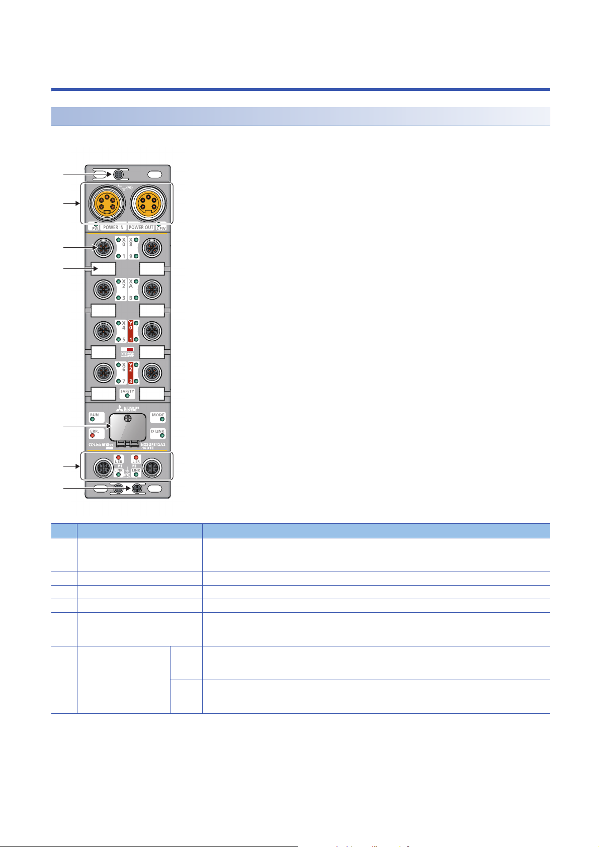
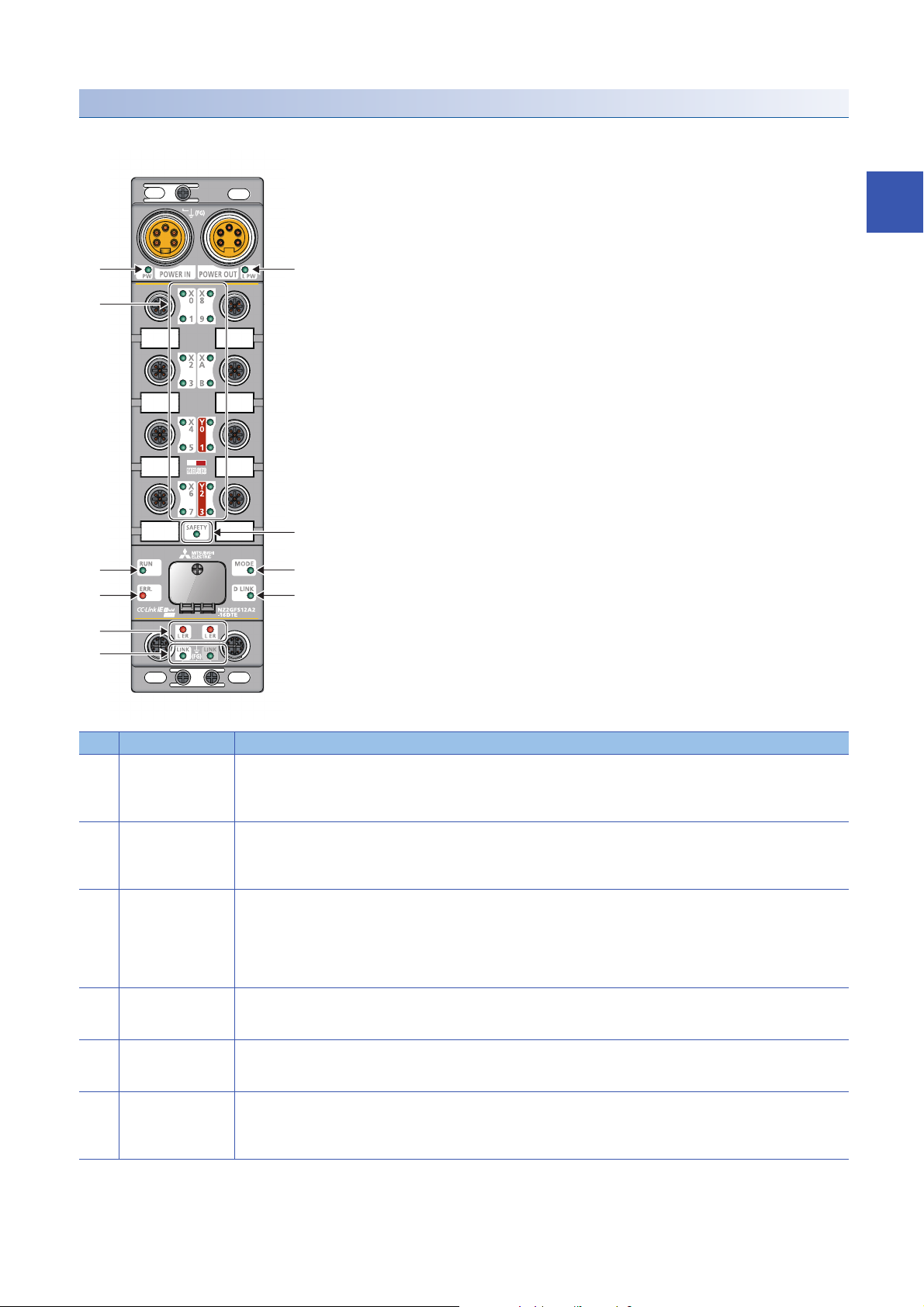
2 PART NAMES
(1)
(2)
(3)
(4)
(5)
(6)
(1)
Part names of the safety remote I/O module
This section describes the part names of the safety remote I/O module.
No. Name Application
(1) FG metal fitting Metal fitting for connecting FG
(2) Power supply connectors Connectors for the module power supply (24VDC) and load power supply (24VDC)
(3) I/O connector Connector for I/O signals
(4) Signal label Label for describing signal names
(5) Station number setting switch Rotary switch for setting a station number or tests
(6) Communication
connectors
P1 PORT1 connector for CC-Link IE Field Network
P2 PORT2 connector for CC-Link IE Field Network
For the tightening torque of screws for the FG metal fitting, refer to the following.
Page 39 Fixing the safety remote I/O module
Page 35 Setting the Station Number
Page 88 Unit Test
Connect an Ethernet cable.
Page 41 Wiring of Ethernet cable
Connect an Ethernet cable.
Page 41 Wiring of Ethernet cable
16
2 PART NAMES
Page 19
Names of the LEDs of the safety remote I/O module
(1) (2)
(3)
(4)
(5) (6)
(7) (8)
(9)
(10)
This section describes the names of the LEDs of the safety remote I/O module.
2
No. Name Description
(1) PW LED Indicates the voltage status of the module power supply.
(2) L PW LED Indicates the voltage status of the load power supply.
(3) I/O LED Indicates the on/off state of I/Os.
(4) SAFETY LED Indicates the safety communication status of the safety remote I/O module.
(5) RUN LED Indicates the operating status of the safety remote I/O module.
(6) MODE LED Indicates the mode of the safety remote I/O module.
Green: The module power supply has no voltage error.
Red: The module power supply has a voltage error.
Off: The module power supply is off or has a voltage error.
Green: The load power supply has no voltage error.
Red: The load power supply has a voltage error.
Off: The load power supply is off or has a voltage error.
Green: I/O signals are on.
Red: An I/O circuit error or double wiring discrepancy was detected.
Red (flashing): An error occurred at one terminal of double wiring, or an error common to all I/O circuits except the terminal
flashing red occurred.
Off: I/O signals are off.
On: Safety communication is established.
Off: Safety communication is not established.
On: Operating normally.
Off: A major error occurred.
On: The unit test is completed. (online)
Flashing: In unit test mode
Off: Error occurred, Offline
2 PART NAMES
17
Page 20
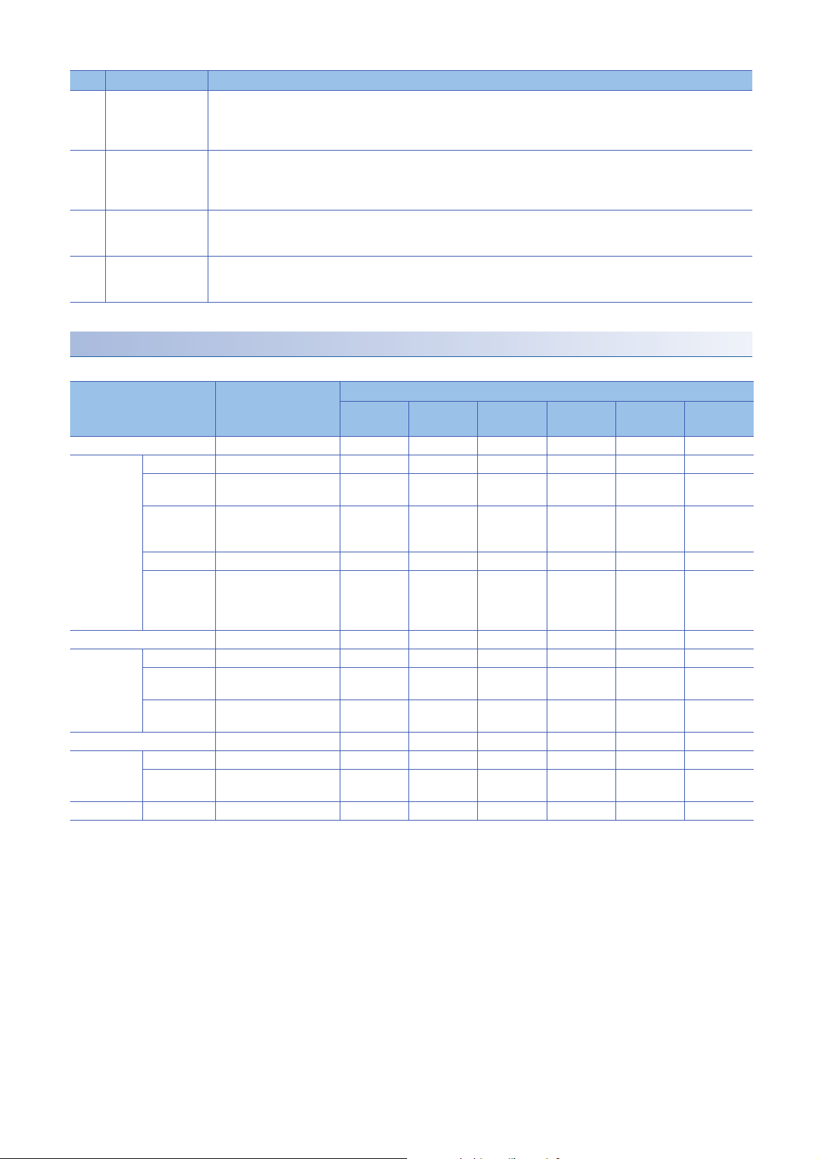
No. Name Description
(7) ERR. LED Indicates the error status of the safety remote I/O module.
(8) D LINK LED Indicates the data link status of the safety remote I/O module.
(9) L ER LED Indicates the port status.
(10) LINK LED
*1
On: A module error occurred.
Flashing: A minor error occurred.
Off: Operating normally.
On: Communications are normal.
Flashing: Communications are interrupted.
Off: Disconnected
On: Module received abnormal data, or module performing loopback.
Off: Module received normal data, or module not performing loopback.
Indicates the link status.
On: Link-up in progress
Off: Link-down in progress
*1 The LINK LED may be on at power-on, but this does not indicate an error.
Safety remote I/O module status and LED status
This section describes the correspondence between the safety remote I/O module status and the LED status.
Safety remote I/O module
*4
status
Initial processing state Disconnection On Off Off Off Off Off
Standby mode Disconnected Disconnection On On On Off Off Off
Data link in
operation
Reserved
station setting
in progress
Link stop Cyclic stop On On On Off Flashing Off
Checking the
position of the
setting target
module
Safety drive mode Data link in operation On On On Off On On
Unit test In progress On On Flashing Off Off Off
Normal
completion
Abnormal
completion
Communication error Cyclic stop On On On Off Flashing Off
Error Major error On Off
Moderate
error
Warning Minor error On On
Data link status LED status
PW LED RUN LED MODE LED ERR. LED D LINK
LED
Data link in operation On On On Off On Off
Cyclic stop On On On Off Flashing Off
Data link in operation/
cyclic stop
On On Off Off Off Off
On On Off On Off Off
On On
On On On Off
*1
*1
*1
On
On
Flashing
*3 *2 *6
*5
*2 *6
*2 *2
SAFETY
LED
Flashing
*1 Either On or Off.
*2 Either On, Flashing, or Off.
*3 When the module is failed, the LED may not turn on.
*4 For the status of the module, refer to the following.
Page 83 Checking Module Status
*5 Either On or Flashing.
*6 Either Flashing or Off.
2 PART NAMES
18
Page 21
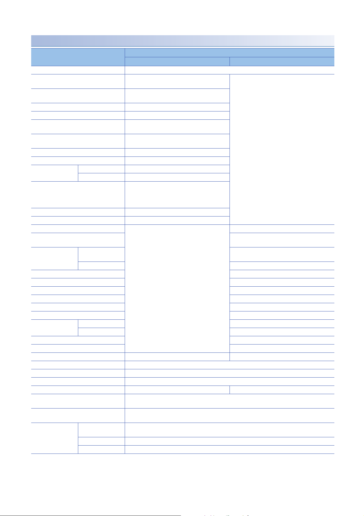
3 SPECIFICATIONS
This chapter describes the specifications of the safety remote I/O module.
3.1 General Specifications
Item Specifications
Operating ambient
temperature
Storage ambient
temperature
Operating ambient
humidity
Storage ambient
humidity
Vibration resistance Compliant with JIS
Shock resistance Compliant with JIS B 3502 and IEC 61131-2 (147m/, 3 times each in X, Y, and Z directions)
Operating atmosphere No corrosive gases
Operating altitude
Installation location Inside/outside a control panel
Overvoltage category
Pollution degree
Equipment class Class
Safety element HFT=1, SIL3 PLe, SC 3, Type B
*1 Only when all necessary waterproof connectors and caps have been installed and the station number setting switch cover has been
properly tightened with a screw, the module conforms to IP67. For the tightening torque range of the screw for the station number setting
switch cover, refer to the following.
Page 36 Tightening torque
*2 Do not use or store the safety remote I/O module under pressure higher than the atmospheric pressure of altitude 0m. Doing so may
cause malfunction. When using the safety remote I/O module under pressure, please consult your local Mitsubishi representative.
*3 This indicates the section of the power supply to which the equipment is assumed to be connected between the public electrical power
distribution network and the machinery within premises.
Category applies to equipment for which electrical power is supplied from fixed facilities. The surge voltage withstand level for the
equipment with the rated voltage of 300V or less is 2500V.
*4 This index indicates the degree to which conductive material is generated in terms of the environment in which the equipment is used.
Pollution degree 2 is when only non-conductive pollution occurs. A temporary conductivity caused by condensing must be expected
occasionally.
0 to 55
-25 to 75
Conforming to IP67
5 to 95%RH, non-condensing
B 3502 and IEC
61131-2
*2
0 to 2000m
*3
or less
*4
2 or less
*1
Frequency Constant
Under intermittent
vibration
Under continuous
vibration
5 to 8.4Hz 3.5mm 10 times each in X,
8.4 to 150Hz 9.8m/
5 to 8.4Hz 1.75mm
8.4 to 150Hz 4.9m/
acceleration
Half amplitude Number of sweeps
Y, and Z directions
3
When complying with the EMC Directive, refer to the following.
Page 126 EMC, Low Voltage, and Machinery Directives
3 SPECIFICATIONS
3.1 General Specifications
19
Page 22
3.2 Performance Specifications
NZ2GFS12A2-16DTE safety remote I/O module
Item NZ2GFS12A2-16DTE
Input specifications Output specifications
Station type Remote device station
Number of input points Single wiring: 12 points
Rated input voltage 24VDC (ripple ratio: 5% or less) (allowable voltage
Rated input current 6mA TYP. (24VDC)
Max. number of simultaneous input points 100%
ON voltage/ON current 11VDC or higher / 2mA or higher (compliant with IEC
OFF voltage/OFF current 5VDC or lower / 1.5mA or lower (compliant with IEC
Input type Negative common
Input resistance Approx. 4k
Input circuit response
time
Safety remote station input response time Input circuit response time + Input ON/OFF delay
Safety refresh response processing time 10ms
Power supply current for input device
Number of output points Single wiring: 4 points
Rated load voltage 24VDC (ripple ratio: 5% or less) (allowable voltage
Load power supply Protection function Load power supply overvoltage protection function,
Max. load current 1.0A/point
Max. inrush current Current is limited by the overload protection function.
Leakage current at OFF 0.1mA or less
Max. voltage drop at ON 1.0VDC or lower
Protection function Output overload short circuit protection
Double output type Source + Source type
Output circuit
response time
Safety remote station output response time Output circuit response time
Surge suppressor Zener diode
Isolation method Non-isolation Photocoupler isolation
Withstand voltage 500VAC for 1 minute between all DC external terminals and the ground
Isolation resistance 10M or higher between all DC external terminals and the ground (500VDC isolation resistance tester)
Protection degree IP67
Wiring method for common Input 12 points/common Output 4 points/common
Interval of the input diagnostic function
execution
Interval of the output diagnostic function
execution
OFF ON 0.5ms or less (24VDC)
ON OFF 1.5ms or less (24VDC)
*1
Max. current 8A
OFF ON 10ms
ON OFF 10ms
Double wiring: 6 points
range: 20.4 to 28.8VDC)
61131-2 Standard digital input type 3)
61131-2 Standard digital input type 3)
setting
(0 to 1000ms in 1ms steps)
(Initial setting: 5ms)
0.4A/1 terminal
12ms maximum
2s maximum
Double wiring: 2 points
range: 20.4 to 28.8VDC)
load power supply overcurrent protection function
20
3 SPECIFICATIONS
3.2 Performance Specifications
Page 23

Item NZ2GFS12A2-16DTE
Input specifications Output specifications
External interface Module power supply
Applicable waterproof
connector
Cyclic transmission RX/RY points 80 points
Communication cable An Ethernet cable that meets the 1000BASE-T standard: Category 5e or higher (double shielded, STP),
Module power supply Voltage 24VDC (ripple ratio: 5% or less) (allowable voltage range: 20.4 to 28.8VDC)
Weight 0.89kg
part
I/O part M12 waterproof connector, 5 pins, female, A-code
Communication part M12 waterproof connector, 8 pins, female, X-code
For power supply Page 14 Recommended Connector List
For I/O
Y-branch connector
for I/O
For communications
RWr/RWw points 16 points
SA\X / SA\Y points SA\X: 28 points
Current (current
consumption)
Protection function Module power supply overvoltage protection function, module power supply overcurrent protection function
Max. current 8A
7/8" waterproof connector, 5 pins, male (IN)/female (OUT)
SA\Y: 4 points
straight cable
190mA
*1 When using the test pulse output for the power supply for input device, use double insulation cables depending on applications used and
the safety category (SIL/CAT) required.
3
3 SPECIFICATIONS
3.2 Performance Specifications
21
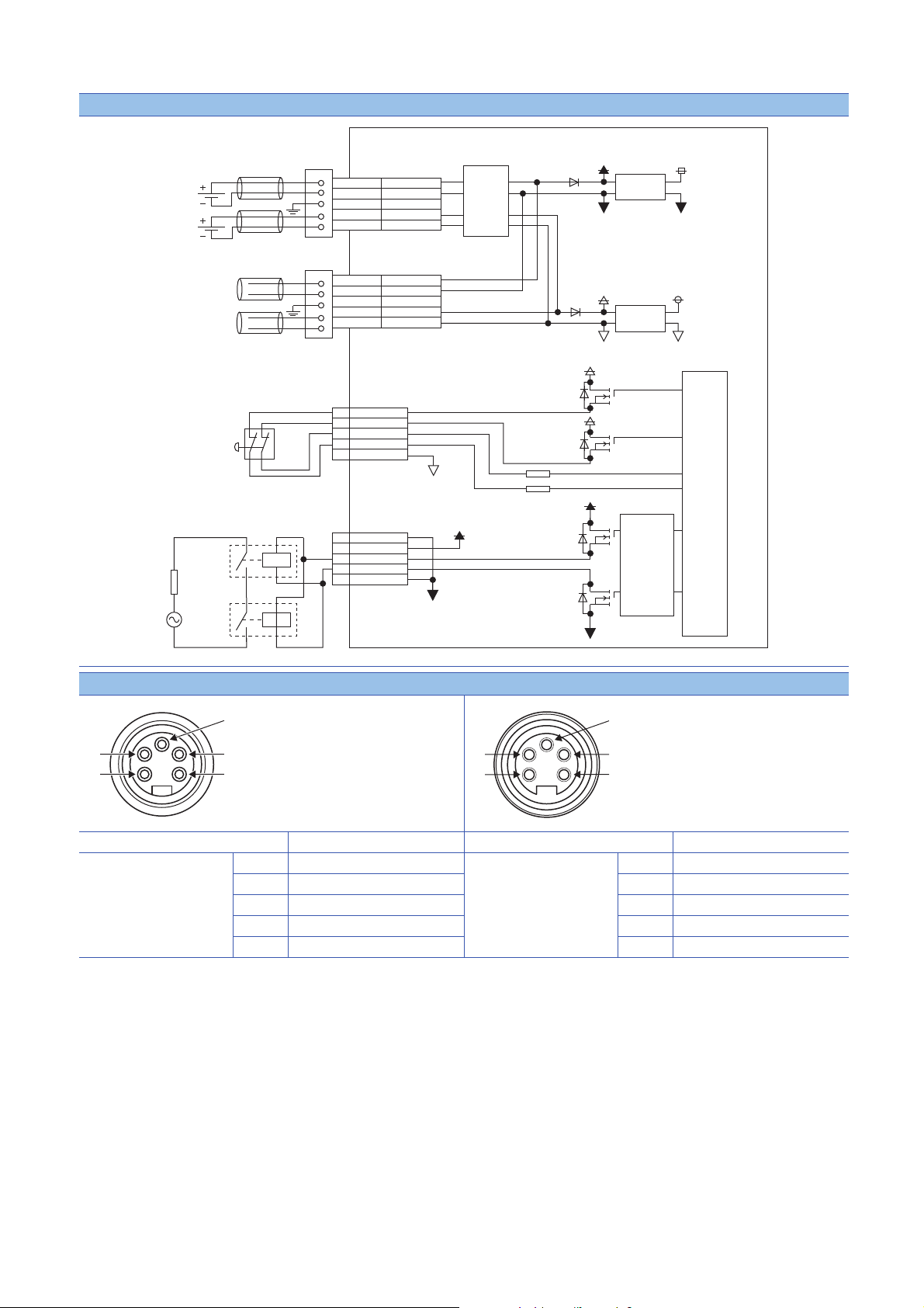
Page 24
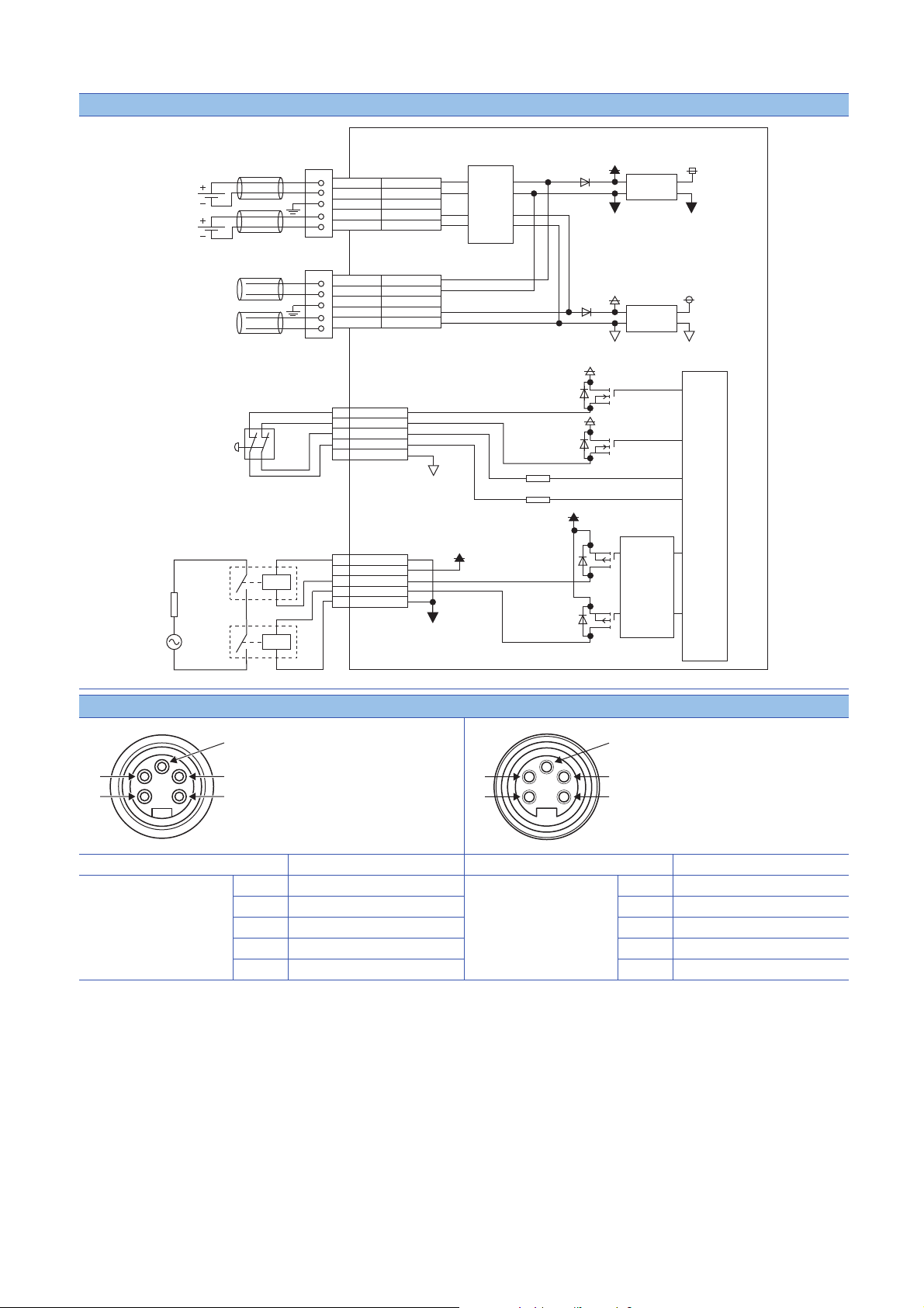
External connection
+24V(L PW_IN)
+24V(PW_IN)
24G(L PW_IN)
24G(PW_IN)
FG
+24V(L PW)
+24V(PW)
24G(L PW)
24G(PW)
24G(PW)
FG
+24V(PW)
+24V(PW)
24G(PW) 24G(PW)
24G(L PW) 24G(L PW)
+24V(PW)
+24V(L PW)
+24V(L PW)
+24V(L PW)
24G(L PW)
DC/DC
DC/DC
POWER IN
POWER OUT
5
1
3
4
2
5
1
3
4
2
5
1
3
4
2
5
1
3
4
2
5
1
3
4
2
24G(PW)
T0
T1
X1
X0
+24V(L PW)
24G(L PW)
24G(L PW)
Y1
Y0
5
1
3
4
2
Load power supply
Module power supply
Safety switch
Power supply connector
Power supply connector
Input
M12 connector
Safety relay
Safety relay
Load
Output
M12 connector
Photocoupler
Internal
circuit
Non-isolation
Internal power
supply (PW)
Internal power
supply (L PW)
Non-isolation
24VDC
24VDC
Current
detection
circuit
(2)
(3)
(1)
(4)
(5)
(4)
(3)
(5)
(2)
(1)
22
Power supply connectors
(1) 24G (L PW)
Pin number Signal name Pin number Signal name
7/8" connector
Male (IN)
3 SPECIFICATIONS
3.2 Performance Specifications
(1) 24G (L PW_IN) 7/8" connector
(2) 24G (PW_IN) (2) 24G (PW)
(3) FG (3) FG
(4) +24V (PW_IN) (4) +24V (PW)
(5) +24V (L PW_IN) (5) +24V (L PW)
Female (OUT)
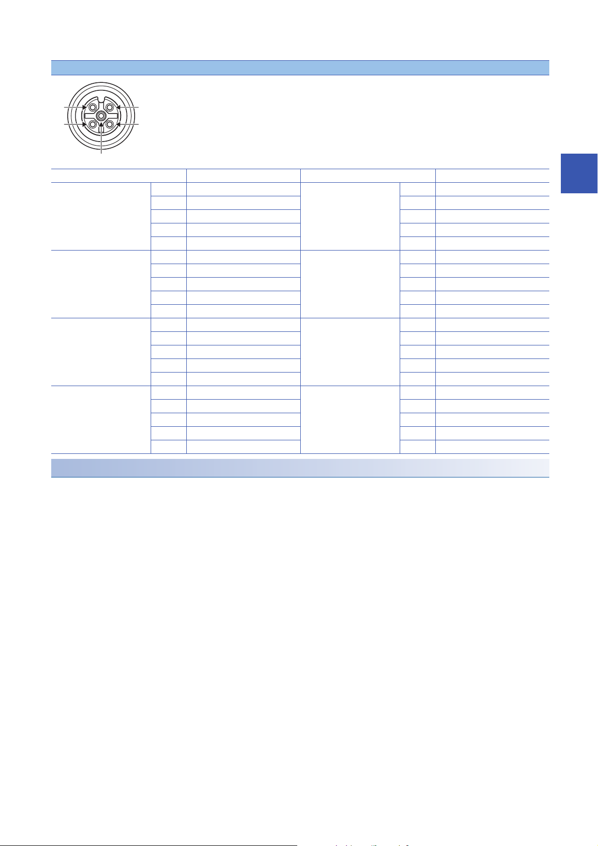
Page 25
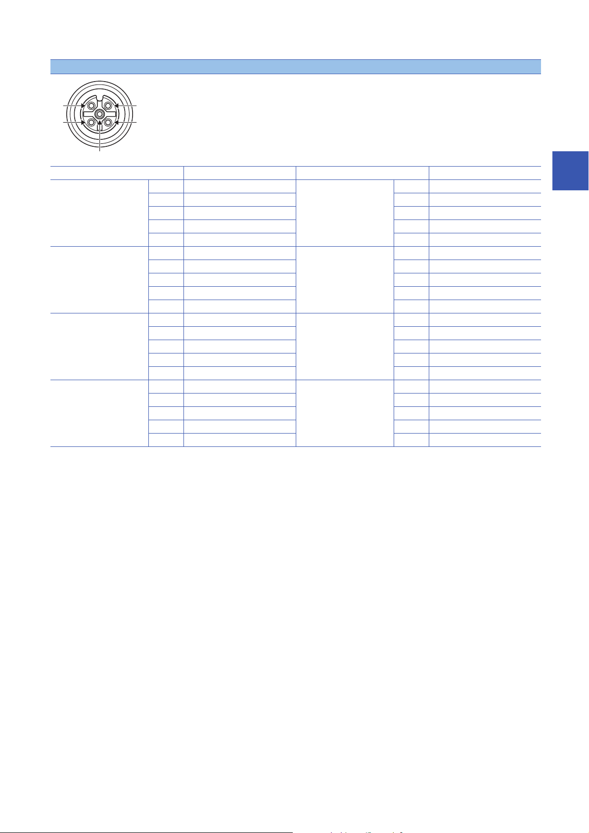
I/O connector
(2)
(3)
(5)
(1)
(4)
Pin number Signal name Pin number Signal name
X0
X1
X2
X3
X4
X5
X6
X7
(1) T1 X8
(2) X1 (2) X9
(3) 24G (PW) (3) 24G (PW)
(4) X0 (4) X8
(5) T0 (5) T8
(1) T3 XA
(2) X3 (2) XB
(3) 24G (PW) (3) 24G (PW)
(4) X2 (4) XA
(5) T2 (5) TA
(1) T5 Y0
(2) X5 (2) Y1
(3) 24G (PW) (3) 24G (L PW)
(4) X4 (4) Y0
(5) T4 (5) 24G (L PW)
(1) T7 Y2
(2) X7 (2) Y3
(3) 24G (PW) (3) 24G (L PW)
(4) X6 (4) Y2
(5) T6 (5) 24G (L PW)
X9
XB
Y1
Y3
(1) T9
(1) TB
(1) +24V (L PW)
(1) +24V (L PW)
3
3 SPECIFICATIONS
3.2 Performance Specifications
23
Page 26
NZ2GFS12A2-14DT safety remote I/O module
Item NZ2GFS12A2-14DT
Input specifications Output specifications
Station type Remote device station
Number of input points Single wiring: 12 points
Double wiring: 6 points
Rated input voltage 24VDC (ripple ratio: 5% or less) (allowable voltage
range: 20.4 to 28.8VDC)
Rated input current 6mA TYP. (24VDC)
Max. number of simultaneous input points 100%
ON voltage/ON current 11VDC or higher / 2mA or higher (compliant with IEC
OFF voltage/OFF current 5VDC or lower / 1.5mA or lower (compliant with IEC
Input type Negative common
Input resistance Approx. 4k
Input circuit response
time
Safety remote station input response time Input circuit response time + Input ON/OFF delay
Safety refresh response processing time 10ms
Power supply current for input device
Number of output points Double wiring: 2 points (single wiring not possible)
Rated load voltage 24VDC (ripple ratio: 5% or less) (allowable voltage
Load power supply Protection function Load power supply overvoltage protection function,
Max. load current 2.0A/point
Max. inrush current Current is limited by the overload protection function.
Leakage current at OFF 0.1mA or less
Max. voltage drop at ON 1.0VDC or lower
Protection function Output overload short circuit protection
Double output type Source + sink type
Output circuit
response time
Safety remote station output response time Output circuit response time
Surge suppressor Zener diode
Isolation method Non-isolation Photocoupler isolation
Withstand voltage 500VAC for 1 minute between all DC external terminals and the ground
Isolation resistance 10M or higher between all DC external terminals and the ground (500VDC isolation resistance tester)
Protection degree IP67
Wiring method for common Input 12 points/common Output 4 points/common
Interval of the input diagnostic function
execution
Interval of the output diagnostic function
execution
External interface Module power supply
OFF ON 0.5ms or less (24VDC)
ON OFF 1.5ms or less (24VDC)
*1
Max. current 8A
OFF ON 10ms
ON OFF 10ms
part
I/O part M12 waterproof connector, 5 pins, female, A-code
Communication part M12 waterproof connector, 8 pins, female, X-code
61131-2 Standard digital input type 3)
61131-2 Standard digital input type 3)
setting
(0 to 1000ms in 1ms steps)
(Initial setting: 5ms)
0.4A/1 terminal
12ms maximum
2s maximum
7/8" waterproof connector, 5 pins, male (IN)/female (OUT)
range: 20.4 to 28.8VDC)
load power supply overcurrent protection function
24
3 SPECIFICATIONS
3.2 Performance Specifications
Page 27
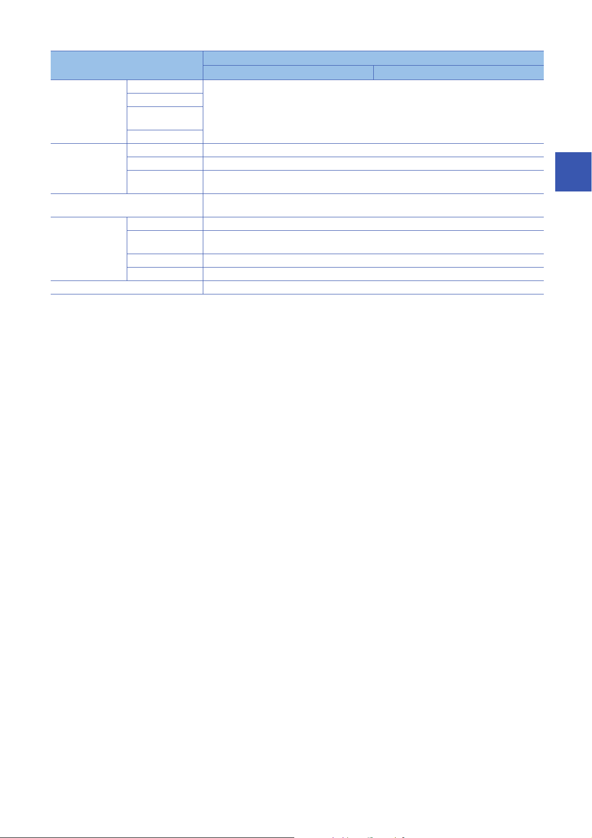
Item NZ2GFS12A2-14DT
Input specifications Output specifications
Applicable waterproof
connector
Cyclic transmission RX/RY points 80 points
Communication cable An Ethernet cable that meets the 1000BASE-T standard: Category 5e or higher (double shielded, STP),
Module power supply Voltage 24VDC (ripple ratio: 5% or less) (allowable voltage range: 20.4 to 28.8VDC)
Weight 0.89kg
For power supply Page 14 Recommended Connector List
For I/O
Y-branch connector
for I/O
For communications
RWr/RWw points 16 points
SA\X / SA\Y points SA\X: 28 points
Current (current
consumption)
Protection function Module power supply overvoltage protection function, module power supply overcurrent protection function
Max. current 8A
SA\Y: 4 points
straight cable
190mA
*1 When using the test pulse output for the power supply for input device, use double insulation cables depending on applications used and
the safety category (SIL/CAT) required.
3
3 SPECIFICATIONS
3.2 Performance Specifications
25
Page 28
External connection
+24V(L PW)
24G(L PW)
+24V(L PW_IN)
+24V(PW_IN)
24G(L PW_IN)
24G(PW_IN)
FG
+24V(L PW)
+24V(PW)
24G(L PW)
24G(PW)
24G(PW)
FG
+24V(PW)
+24V(PW)
24G(PW)
24G(L PW)
24G(PW)
24G(L PW)
+24V(PW)
+24V(L PW)
+24V(L PW)
24G(L PW)
DC/DC
DC/DC
POWER IN
POWER OUT
5
1
3
4
2
5
1
3
4
2
5
1
3
4
2
5
1
3
4
2
5
1
3
4
2
24G(PW)
T0
T1
X1
X0
+24V(L PW)
24G(L PW)
24G(L PW)
Y0+
Y0-
5
1
3
2
4
Load power supply
Module power supply
Safety switch
Power supply connector
Power supply connector
Input
M12 connector
Safety relay
Safety relay
Load
Output
M12 connector
Photocoupler
Internal
circuit
Non-isolation
Internal power
supply (PW)
Internal power
supply (L PW)
Non-isolation
24VDC
24VDC
Current
detection
circuit
(2)
(3)
(1)
(4)
(5)
(4)
(3)
(5)
(2)
(1)
Power supply connectors
(1) 24G (L PW)
Pin number Signal name Pin number Signal name
7/8" connector
Male (IN)
(1) 24G (L PW_IN) 7/8" connector
(2) 24G (PW_IN) (2) 24G (PW)
Female (OUT)
(3) FG (3) FG
(4) +24V (PW_IN) (4) +24V (PW)
(5) +24V (L PW_IN) (5) +24V (L PW)
26
3 SPECIFICATIONS
3.2 Performance Specifications
Page 29
I/O connector
(2)
(3)
(5)
(1)
(4)
Pin number Signal name Pin number Signal name
X0
X1
X2
X3
X4
X5
X6
X7
(1) T1 X8
(2) X1 (2) X9
(3) 24G (PW) (3) 24G (PW)
(4) X0 (4) X8
(5) T0 (5) T8
(1) T3 XA
(2) X3 (2) XB
(3) 24G (PW) (3) 24G (PW)
(4) X2 (4) XA
(5) T2 (5) TA
(1) T5 Y0 (1) +24V (L PW)
(2) X5 (2) Y0-
(3) 24G (PW) (3) 24G (L PW)
(4) X4 (4) Y0+
(5) T4 (5) 24G (L PW)
(1) T7 Y1 (1) +24V (L PW)
(2) X7 (2) Y1-
(3) 24G (PW) (3) 24G (L PW)
(4) X6 (4) Y1+
(5) T6 (5) 24G (L PW)
X9
XB
(1) T9
(1) TB
3
Safety remote I/O module safety response time
The safety response time of the safety remote I/O module is shown below.
For the response time including the network delay time, refer to the following.
Mitsubishi Electric Safety Programmable Controller MELSEC iQ-R Series Machinery Directive (2006/42/EC) Compliance
■Input
Transmission interval monitoring time 2 + Safety remote station input response time
■Output
Transmission interval monitoring time 2 + Safety remote station output response time
3 SPECIFICATIONS
3.2 Performance Specifications
27
Page 30

3.3 Function List
This section describes the function list, operation modes, and state transition.
Function list
■I/O functions
Function name Description Reference
Input function Input wiring selection
Output function Output wiring selection
function
Input ON delay, input OFF
delay functions
function
■Safety functions
Function name Description Reference
Input diagnostic
function
Output diagnostic
function
Double input discrepancy
detection function
Input dark test function This function outputs test pulses to turn off the external input
Output dark test function This function outputs test pulses to turn off the external output
Output read-back function This function reads back output results and diagnoses whether the
This function selects double wiring or single wiring of the input
wiring.
This function changes an input signal when a predetermined time
has passed after an actual input change.
A delay time can be set for each input change pattern, OFF to ON
or ON to OFF. In addition, the function prevents incorrect inputs
caused by noise since a pulse of a certain time length is not taken
in a module.
This function selects double wiring or single wiring of the output
wiring.
This function discriminates failures by monitoring the discrepancy
state of doubled safety remote inputs (SA\X).
When the discrepancy state is detected, a minor error occurs. The
module will recover from the error by eliminating its cause.
signals (X0 to XB) that are on for a short time and diagnoses
contacts including external devices for failure.
When failure is detected, a minor error occurs. The module will
recover from the error by eliminating its cause.
To use this function, settings of "Input mode setting" and "Input test
pulse setting" are required.
signals (NZ2GFS12A2-16DTE: Y0 to Y3, NZ2GFS12A2-14DT: Y0
to Y1) that are on for a short time and diagnoses the internal circuit
for failure.
When failure is detected, a minor error occurs. The module will
recover from the error by eliminating its cause.
external output signals (NZ2GFS12A2-16DTE: Y0 to Y3,
NZ2GFS12A2-14DT: Y0 to Y1) are correctly output.
When an incorrect output is detected, a minor error occurs. The
module will recover from the error by eliminating its cause.
*1
*1
*1
Page 45 Input wiring selection
function
Page 49 Input ON delay, input OFF
delay functions
Page 50 Output wiring selection
function
Page 53 Double input discrepancy
detection function
Page 55 Input dark test function
Page 57 Output dark test function
Page 59 Output read-back function
*1 This operation differs from the operation of CC-Link IE Field Network remote I/O module (with safety functions). For the system,
configure an external interlock circuit or an interlock circuit using a ladder program. Do not use a stop of safety remote I/O module as an
interlock condition.
For the operation of CC-Link IE Field Network remote I/O module (with safety functions), refer to the following.
CC-Link IE Field Network Remote I/O Module (With Safety Functions) User's Manual
3 SPECIFICATIONS
28
3.3 Function List
Page 31

■Network function
Function name Description Reference
User authentication function This function limits the users who can access the Safety CPU or
safety remote I/O module.
Page 60 User Authentication
Function
■Module function
Function name Description Reference
Protection function This function protects the internal circuit from overvoltage or
overcurrent.
The safety remote I/O module does not support the CC-Link IE Field Network synchronous communication
function.
Page 61 Protection Functions
3
3 SPECIFICATIONS
3.3 Function List
29
Page 32

Operation mode and state transition
a
b
c
d
f
g
g
g
g
h
f
f
e
(1) Power supply OFF state
(2) Initial processing state (3) Unit test mode
(4) Standby mode
*1
(6) Moderate error state
(7) Major error state
(5) Safety drive mode
*1
The following describes the state transition and transition conditions of the safety remote I/O module.
*1 When a moderate error or major error has occurred, the state is changed into an error state.
■Operation mode/state
No. Mode/state Description
(1) Power supply OFF state The power supply is not turned on. Change the station number using the station number setting switch or wire
(2) Initial processing state The initial processing is performed at this state.
(3) Unit test mode The unit test is performed at this state.
(4) Standby mode The safety functions of the safety remote I/O module do not operate at this state. Set parameters in this
(5) Safety drive mode The safety functions of the safety remote I/O module operate at this state.
(6) Moderate error state A moderate error has occurred.
(7) Major error state A major error has occurred.
the module at this state.
Page 35 INSTALLATION AND WIRING
Page 88 Unit Test
mode.
Page 62 PARAMETER SETTINGS
■Transition condition
Symbol Transition condition
a When the module is powered on
b When the station number setting switch 10 is set to TEST and the station number setting switch 1 is set to 0 in the power supply OFF state
c When the initial processing is completed successfully
d When Safety module enabled flag (address: 1005H) is on and the safety communication with the master station is established
e When the safety communication is disconnected
f When a moderate error has occurred
g When a major error has occurred
h When a parameter data error is eliminated. For parameter data errors, refer to the following.
30
3 SPECIFICATIONS
3.3 Function List
For Safety module enabled flag (address: 1005H), refer to the following.
Page 125 Safety module enabled flag (address: 1005H)
Page 95 Error Code List
To switch the operation mode/state from the unit test mode, moderate error state, or major error state, power
off and on the module.
Page 33

4 PROCEDURES BEFORE OPERATION
Consideration of system configuration
Complete the following items prior to the module installation.
1. Determine a safety category required for configuring the safety system.
2. Determine function wiring required for configuring the safety system.
3. Determine the network number and station number of the safety remote I/O module.
Module mounting, wiring, and parameter setting
1. Mounting the module
Fix the safety remote I/O module with screws.
Page 37 Installation Environment and Installation Position
2. Wiring to the power supply module
Connect the safety remote I/O module to the power supply.
Page 40 Wiring the power supply
3. Station number setting
Set station numbers of the safety remote I/O module using the station number setting switch.
Page 35 Setting the station number with the station number setting switch
4. Wiring
Connect the Ethernet cable and external devices to the safety remote I/O module.
Page 41 Wiring of Ethernet cable
5. Powering on the safety remote I/O module
Stop the Safety CPU, and power on the safety remote I/O module.
6. Parameter setting
Set the module parameters of the master station module and the safety remote I/O module in the engineering tool.
Page 62 PARAMETER SETTINGS
Page 64 Module Parameter Setting of the Master Station
Page 67 Module Parameter Setting
4
7. Checking the entire system
According to the manuals of the Safety CPU and the master station module, check the entire system for wiring, the station
number setting switch, and so on.
8. Validating the safety remote I/O module
Enable the module parameters of the safety remote I/O module.
Page 67 Module parameter setting procedure
9. Starting the system
Change the status of the Safety CPU to RUN.
10. Starting the system operation
To replace the module, follow the procedure described below:
• Turn off the module power supply and remove the safety remote I/O module.
• Prepare a new safety remote I/O module and perform the procedure above from "Mounting the module" to
"Parameter setting". (The network parameter of the master station does not need to be set again.)
• After checking the operation, restart the control.
4 PROCEDURES BEFORE OPERATION
31
Page 34

MEMO
32
4 PROCEDURES BEFORE OPERATION
Page 35

5 SYSTEM CONFIGURATION
This chapter describes the system configuration using a safety remote I/O module.
For CC-Link IE Field Network configuration, refer to the following.
User's manual for the master/local module used
5.1 Applicable Systems
Applicable products
When using a safety remote I/O module, use the following products.
For the model of the Safety CPU and safety function module, refer to the following.
MELSEC iQ-R Module Configuration Manual
Module Firmware version
Safety CPU (RnSFCPU) 01 or later
Safety function module (R6SFM) 01 or later
Master station (RJ71GF11-T2) 09 or later
Master station (RD77GF4, RD77GF8, RD77GF16, RD77GF32) 05 or later
Information on "Master station" described above is the ones at the point when this manual was issued.
For latest information, please visit the website of CC-Link Partner Association.
www.cc-link.org
5
The safety remote I/O module cannot be used with a CPU module other than the Safety CPU.
Ethernet cable
For the specifications of the Ethernet cable, refer to the following.
MELSEC iQ-R Ethernet/CC-Link IE User's Manual (Startup)
Software package
The following engineering tool is required for the safety remote I/O module setting and CC-Link IE Field Network diagnostics.
Product name Version
GX Works3 1.050C or later
When the latest profile of the safety remote I/O module is necessary, please consult your local Mitsubishi
representative.
The profile is a setting file that stores information required for the start-up, operation, and maintenance of
devices supporting the CC-Link family. A module is added to "Module List" of "CC IE Field Configuration"
window by profile registration to an engineering tool. For the profile registration, refer to the following.
GX Works3 Operating Manual
5 SYSTEM CONFIGURATION
5.1 Applicable Systems
33
Page 36

5.2 Safety Standards
Observe the following safety standards.
Region Standard
Global IEC 61508: 2010, IEC 62061: 2012, ISO 13849-1
IEC 61131-2
IEC 61000-6-2, IEC 61000-6-4
IEC 61784-3
IEC 60204-1
IEC 61326-3-1
Europe EN ISO13849-1
North America UL 61010-1, UL 61010-2-201
EN 61131-2
EN 61000-6-2, EN 61000-6-4
5.3 Safety Parameters
The following table lists safety parameters of the safety remote I/O module.
Item NZ2GFS12A2-16DTE NZ2GFS12A2-14DT
*1
PFDavg
*1
PFH
DCavg 96.28% 96.24%
MTTFd 108 years 109 years
MTBF 195.7 years (40) 207.4 years (40)
4.0710
4.7010
-4
-9
4.0710
4.6910
-4
-9
*1 Proof test interval is 20 years (module exchange interval).
34
5 SYSTEM CONFIGURATION
5.2 Safety Standards
Page 37

6 INSTALLATION AND WIRING
This chapter describes the installation and wiring of the safety remote I/O module.
6.1 Setting the Station Number
Setting the station number with the station number setting switch
Setting procedure
Set a station number with the station number setting switch on the front of the module. The setting value of the station number
becomes valid when the module is powered on. Thus, set the station number when the module is powered off.
1. Loosen the screw for the station number setting switch
cover with a screwdriver and open the cover.
6
2. Set a station number.
• The hundreds and tens places of the station number are set with x10.
• The ones place of the station number is set with x1.
*1
3. After setting the station number with the station number
setting switch, always close the station number setting
switch cover and tighten the screw for the cover with a
*2
screwdriver.
not been tightened properly, waterproof performance is
lost.
*1 When operating the station number setting switch, use a flathead screwdriver with 3.5mm or less width of the tip.
*2 For the tightening torque range of the screw for the station number setting switch cover, refer to the following.
Page 36 Tightening torque
When the cover is open or the screw has
6 INSTALLATION AND WIRING
6.1 Setting the Station Number
35
Page 38

Ex.
To set the station to 115, set the switch as shown below.
Setting range
Set the station number from 1 to 120. Setting the value other than 1 to 120 causes a communication error and the D LINK
LED flashes.
• Do not change the station number setting switch while the module power supply is on. Changing the station
number setting switch causes a minor error and the ERR. LED flashes. Returning the station number setting
switch to the previous setting eliminates the error five seconds later and the ERR. LED turns off.
• Do not set a same station number as another station number. If a duplicate station number is used, a
communication error occurs and the D LINK LED does not turn on.
Tightening torque
Tighten the screw for the station number setting switch cover within the following tightening torque range.
Screw type Tightening torque range
Station number setting switch cover (M3 screw) 0.43 to 0.57Nm
• Do not put oil on the screw. Failure to do so may damage the screw.
• Tighten the screw with an applicable screwdriver. Tightening it with an inapplicable screwdriver may
damage the screw.
36
6 INSTALLATION AND WIRING
6.1 Setting the Station Number
Page 39

6.2 Installation Environment and Installation Position
Installation environment
Installation location
Do not install the safety remote I/O module to a place where:
• Ambient temperature is outside the range of 0 to 55;
• IP67 is not satisfied;
• Condensation occurs due to rapid temperature change;
• Corrosive gas or combustible gas is present;
• Conductive powder such as iron powder, oil mist, salinity, or organic solvent is filled;
• The safety remote I/O module is exposed to direct sunlight;
• A strong electric field or strong magnetic field is generated; and
• The safety remote I/O module is subject to vibration and shock.
Installation surface
Install the safety remote I/O module on a flat surface. When the installation surface is uneven, excessive force is applied to
the printed-circuit board and may cause a defect.
6
6 INSTALLATION AND WIRING
6.2 Installation Environment and Installation Position
37
Page 40

Installation position
(2)
(1)
(2)
(1)
(2)
When installing the safety remote I/O module, provide a clearance between the module and the sides of neighboring
structures or parts to ensure good ventilation, avoid interference, and avoid stress on waterproof connectors.
To insert or remove a communication connector, provide a clearance sufficient to use a screwdriver.
When using a right-angle, waterproof connector or a Y branch connector, provide a clearance to avoid stress on cables.
(1) 0mm or longer
(2) 50mm or longer
Installation direction
The safety remote I/O module can be installed in six directions.
Fix the module with screws.
38
6 INSTALLATION AND WIRING
6.2 Installation Environment and Installation Position
Page 41

6.3 Installation
Fixing the safety remote I/O module
When fixing the safety remote I/O module, tighten all of four screws.
Otherwise, the module will be greatly affected by vibration, causing failure of the module.
When installing the module, tighten screws within the following torque range.
Screw type Tightening torque range
Module mounting screw (M4 screw) 0.824 to 1.11Nm
Screw for an FG metal fitting (M3 screw) 0.425 to 0.575Nm
• Do not put oil on the screw. Failure to do so may damage the screw.
• Tighten the screw with an applicable screwdriver. Tightening it with an inapplicable screwdriver may
damage the screw.
6
6 INSTALLATION AND WIRING
6.3 Installation
39
Page 42

6.4 Wiring
*1
(1)
Wiring the power supply
When wiring the power supply, connect it to the POWER IN terminal of the power supply connector of the safety remote I/O
module.
Transition wiring of the power supply
When installing multiple safety remote I/O modules, the power can be supplied to the modules through transition wiring.
For transition wiring, connect wires between the POWER OUT terminal of the safety remote I/O module that will be the power
supplier and the POWER IN terminal of another safety remote I/O module that will be a power supply destination.
*1 The largest current flows from the power supplier to the power supply connector of the first safety remote I/O module. Make sure that the
current does not exceed the current capacity (8A/pin) of the power supply connector. For a power supply to supply 24VDC, use a power
supply (SELV power supply) that does not exceed 30VAC (effective value), 42.4V (peak value), or 60VDC. Also, use a power supply
which is applied to "limited-energy circuit" defined in IEC61010-1.
(1) Power supply
For transition wiring, check the current consumption of each of the wired safety remote I/O modules.
For the current consumption of a safety remote I/O module, refer to the following.
Page 20 Performance Specifications
40
6 INSTALLATION AND WIRING
6.4 Wiring
Page 43

Wiring of Ethernet cable
Connecting the Ethernet cable
■Connecting
1. Power off the module power supply of the
safety remote I/O module and the power supply
of the external device.
2. Push the Ethernet cable connector into the
safety remote I/O module, paying attention to
the connector's direction.
6
3. Tighten the screw of the Ethernet cable.
4. Power on the module power supply.
5. Power on the power supply of the external
device.
6. Check that the LINK LED on the port into which
the Ethernet cable is connected is on.
*1 The time taken for the LINK LED to turn on after connection of the cable may vary. The LINK LED normally turns on in a few second.
However, if link-up processing is repeated due to a condition of a device on the line, the longer time may be required. If the LINK LED
does not turn on, refer to the following and take a corrective action.
Page 82 When the LINK LED turns off
*1
6 INSTALLATION AND WIRING
6.4 Wiring
41
Page 44

• PORT1 and PORT2 need not be distinguished. When only one connector is used in star topology, either
PORT1 or PORT2 can be connected.
• When two connectors are used in line topology or ring topology, an Ethernet cable can be connected to the
connectors in any combination. For example, the cable can be connected between PORT1s and between
PORT1 and PORT2.
• Connection between PORT1 and PORT1 or between PORT2 and PORT2
• Connection between PORT1 and PORT2
42
6 INSTALLATION AND WIRING
6.4 Wiring
Page 45

■Disconnecting
1. Power off the module power supply.
2. Loosen the screw of the Ethernet cable and
remove the Ethernet cable.
Precautions
■Laying Ethernet cables
• Place the Ethernet cables in a duct or clamp them. If not, dangling cable may swing or inadvertently be pulled, resulting in
damage to the module or cables or malfunction due to poor contact.
• Do not touch the core of the connector of the cable or the module, and protect it from dirt and dust. If any oil from your hand,
or any dirt or dust sticks to the core, it can increase transmission loss, causing data link to fail.
• Check the following:
• Is any Ethernet cable disconnected?
• Does any Ethernet cable short?
• Are the connectors securely connected?
6
■Connecting and disconnecting the Ethernet cable
Hold the connector part when connecting and disconnecting the Ethernet cable. Pulling the cable connected to the module
may result in damage to the module or cable or malfunction due to poor contact.
■Connectors without Ethernet cable
To prevent dust from entering the module, attach the provided waterproof caps.
■Maximum station-to-station distance (Maximum Ethernet cable length)
The maximum station-to-station distance is 100m. However, the distance may be shorter depending on the operating
environment of the cable. For details, contact the manufacturer of the cables used.
■Bending radius of the Ethernet cable
There are restrictions on the bending radius of the Ethernet cable. Check the bending radius in the specifications of the
Ethernet cables used.
Attaching waterproof caps
Tighten the waterproof caps within the following torque range.
Screw type Tightening torque range
Waterproof cap 0.30 to 0.34Nm
6 INSTALLATION AND WIRING
6.4 Wiring
43
Page 46

Precautions for wiring the safety remote I/O module to safety devices
This section describes the precautions for the wiring. To wire the safety remote I/O module to each safety device according to
Category 4, perform both of the following for the safety remote I/O module.
• Double wiring inputs
Page 45 Double wiring function
• Double wiring outputs
Page 50 Double wiring function
• Executing the self-diagnostic function (dark test)
Page 55 Input dark test function
Page 57 Output dark test function
44
6 INSTALLATION AND WIRING
6.4 Wiring
Page 47

7 FUNCTIONS
NC
NC
T0 T1 X0 X1
Two inputs
Safety remote I/O module
NC
NO
T0 T1 X0 X1
Two inputs
Safety remote I/O module
This chapter describes the functions available in the safety remote I/O module, and the setting procedures for those functions.
For details on safety remote I/O signals, remote I/O signals, and remote buffer memory, refer to the following.
• Page 104 Safety Remote I/O Signals
• Page 108 Remote I/O Signals
• Page 113 Remote Buffer Memory
7.1 Input Function
This function safely inputs external signals. This function cannot be used in any modes other than the safety drive mode. All
the safety remote inputs (SA\X) are off in any modes other than the safety drive mode.
Input wiring selection function
This function selects double wiring or single wiring of the input wiring.
Double wiring function
The double wiring function supports double input wiring.
By verifying input signals of double wiring, safety inputs can be turned off even though one of the signals has an error.
The following two are the double wiring methods for safety remote input (SA\X).
• Double wiring example for input (NC/NC)
7
• Double wiring example for input (NC/NO)
7 FUNCTIONS
7.1 Input Function
45
Page 48

■Combination for double wiring
T0 X0
NC
Safety remote I/O module
Use the following combinations of input terminals for double wiring to the safety remote I/O module.
Combination of input terminals
X0, X1 X2, X3 X4, X5 X6, X7 X8, X9 XA, XB
The following table lists the relation of input terminals (X) and safety remote inputs (SA\X).
Safety remote input (SA\X) Input terminal (X)
SA\X0 X0
SA\X1 X1
to to
SA\XA XA
SA\XB XB
Single wiring function
This function can connect input devices with single wiring.
Connecting input devices with single wiring brings the safety category to SIL2/CAT2 PLd.
Diagnostic functions to detect input errors
Input errors can be detected by using the following diagnostic functions.
Diagnostic function Description Reference
Double input discrepancy detection
function
Input dark test function Outputs test pulses to turn off the external input signals (X0 to XB) that are on
Detects the discrepancy of double input signals. Page 53 Double input
discrepancy detection function
Page 55 Input dark test function
for a short time and diagnoses contacts including external devices for failure.
46
7 FUNCTIONS
7.1 Input Function
Page 49

Combination of double inputs
(1)
(2)
ON
OFF
ON
OFF
ON
OFF
ON
OFF
Double input
discrepancy state
Input terminal status: X0
Input terminal status: X1
SA\X0
SA\X1
The safety remote I/O module evaluates the logic of input signals and reflects the results to safety remote inputs (SA\X).
When the double input signals differ, the double input discrepancy detection state is applied. The following tables list the
correspondence between each double input signal state and safety remote input (SA\X).
■Combination of double inputs (NC/NC)
Input terminal state Safety remote input
(SA\X0 to SA\XB)
*1
Xn
OFF OFF OFF OFF ON ON Off Off OFF (Normal)
OFFON OFFOFFOFF
ON OFF OFF OFF OFF
ON ON ON ON ON ON Green Green ON (Normal)
Xn+1
*1
SA\Xm*2SA\Xm+
*2
1
*1 n: Even number from 0 to A
*2 m: Safety device address (even number from 0 to A) assigned to the master station
*3 After the double input discrepancy time has elapsed, the status changes to the listed status.
■Combination of double inputs (NC/NO)
Input terminal state Safety remote input
(SA\X0 to SA\XB)
*1
Xn
OFF OFF OFF ON OFF OFF Red
OFF ON OFF ON ON ON Off Green OFF (Normal)
ON OFF ON OFF ON ON Green Off ON (Normal)
ON ON OFF ON OFF OFF Red
Xn+1
*1
SA\Xm*2SA\Xm+
*2
1
Safety input status
(SA\XC to SA\X17)
SA\XC+
*2
m
SA\XC+
*2
m+1
*3
*3
OFF
OFF
*3
*3
Safety input status
(SA\XC to SA\X17)
SA\XC+
*2
m
SA\XC+
*2
m+1
I/O LED status Evaluation result of double inputs
Xn
Red
Red
*1
*3
*3
Xn+1
Red
Red
*1
*3
*3
OFF (Discrepancy)
OFF (Discrepancy)
I/O LED status Evaluation result of double inputs
Xn
*1
*3
*3
Xn+1
Red
Red
*1
*3
*3
OFF (Discrepancy)
ON (Discrepancy)
7
*1 n: Even number from 0 to A
*2 m: Safety device address (even number from 0 to A) assigned to the master station
*3 After the double input discrepancy time has elapsed, the status changes to the listed status.
■States of safety remote inputs (SA\X0, SA\X1) for X0 and X1 (double wiring (NC/NC))
(1) Even when the input terminal X0 turns on, SA\X0 does not turn on because X1 is off.
(2) When the double inputs are on (X0 and X1 are on), SA\X0 and SA\X1 turn on.
Even when SA\X0 and SA\X1 are off, the time when X0 and X1 are in double input discrepancy state is measured and if the measured time exceeds a set
detection time, a double input discrepancy detection error occurs.
7 FUNCTIONS
7.1 Input Function
47
Page 50

■States of safety remote inputs (SA\X0, SA\X1) for X0 and X1 (double wiring (NC/NO))
(1)
OFF
ON
OFF
ON
OFF
ON
OFF
ON
SA\X0
SA\X1
Double input
discrepancy state
Input terminal status: X0
Input terminal status: X1
(1) The same value as the input terminal is reflected.
Even when SA\X0 and SA\X1 are off, the time when X0 and X1 are in double input discrepancy state is measured and if the measured time exceeds a set
detection time, a double input discrepancy detection error occurs.
Setting procedure
Set the input wiring selection in "Wiring selection of input" from the "Parameter Processing of Slave Station" window of the
engineering tool.
For the procedure to display the "Parameter Processing of Slave Station" window, refer to the following.
Page 67 Module parameter setting procedure
Item Setting range
Wiring selection of input X0/X1 to XA/XB 1: Double wiring (NC/NC) (default)
2: Double wiring (NC/NO)
3: Single wiring
External input signal monitor function
The state of input terminals can be monitored. This function facilitates the investigation for the cause of a double input
discrepancy error. For details, refer to the following.
Page 111 External input monitor (RX30 to RX3F)
When "Wiring selection of input" is set to "3: Single wiring", both Xn and Xn+1 are single wiring.
External input monitors (RX30 to RX3F) are the remote control/monitor signals to investigate the cause of a
double input discrepancy error. Do not use them in a safety program.
48
7 FUNCTIONS
7.1 Input Function
Page 51

Input ON delay, input OFF delay functions
Ex.
Ex.
This function changes an input signal when a predetermined time has passed after an actual input change.
A delay time can be set for each input change pattern, OFF to ON or ON to OFF. In addition, the function prevents incorrect
inputs caused by noise since a pulse of a certain time length is not taken in a module.
Input ON delay
The ON delay is the minimum ON time of the actual input signal required before the safety input signal changes from OFF to
ON.
When 5ms is set, the safety input signal turns to ON after the actual input signal is ON for at least 5ms.
Input OFF delay
The OFF delay is the minimum OFF time of the actual input signal required before the safety input signal changes from ON to
OFF.
When 5ms is set, the safety input signal turns to OFF after the actual input signal is OFF for at least 5ms.
Setting procedure
The "Input ON delay" and "Input OFF delay" times can be set from the "Parameter Processing of Slave Station" window of the
engineering tool.
The setting range is 0 to 1000ms (in 1ms steps)
The default value is 5ms.
7
• When "Wiring selection of input" is set to "1: Double wiring (NC/NC)" or "2: Double wiring (NC/NO), set the
same value as Xn+1 for Xn (n: even number).
• When "Input mode setting" is set to "1: Not used", this parameter will be ignored.
• In addition to this setting value, the safety refresh response processing time and the hardware response
time are also added as delay time for safety input signal switching. (Safety refresh response processing
time: 10ms, hardware response time: OFFON (0.5ms), ONOFF (1.5ms))
7 FUNCTIONS
7.1 Input Function
49
Page 52

7.2 Output Function
MC
MC
Y1
Y0
24G(L PW)
24G(L PW)
+24V(L PW)
Load
Load
Load power supply
Safety remote I/O module
Y0+
Y0-
+24V(L PW)
24G(L PW)
Load power supply
Safety remote I/O module
Safety relay
Safety relay
LoadLoad
This function safely outputs signals. This function cannot be used in any modes other than the safety drive mode. All the
safety remote outputs (SA\Y) are off in any modes other than the safety drive mode.
Output wiring selection function
This function selects double wiring or single wiring of the output wiring.
Double wiring function
The double wiring function supports double outputs. By multiplying output signals using double wiring, safety outputs can be
turned off even though one of the signals has an error.
The following two are the double wiring methods for safety remote output (SA\Y).
■Double wiring for output (source + source connection)
■Double wiring for output (source + sink connection)
■Combination for double wiring
Use the following combinations of output terminals for double wiring to the safety remote I/O module.
Combination of output terminals
Double wiring (source + source connection) Double wiring (source + sink connection)
Y0, Y1 Y2, Y3 Y0+, Y0- Y1+, Y1-
50
7 FUNCTIONS
7.2 Output Function
Page 53

Single wiring function (NZ2GFS12A2-16DTE)
MC
Y0
24G(L PW)
24G(L PW)
+24V(L PW)
LoadLoad power supply Safety remote I/O module
This function can connect output devices with single wiring.
Connecting output devices with single wiring brings the safety category to SIL2/CAT2 PLd.
Diagnostic functions to detect output errors
Output errors can be detected by using the following diagnostic functions.
Diagnostic function Description Reference
Output dark test function Outputs test pulses to turn off the outputs that are on for a short time and
diagnoses the internal circuit for failure.
Output read-back function Reads back output results and diagnoses whether the outputs are correctly
on or off.
Page 57 Output dark test
function
Page 59 Output read-back
function
7
Combination of double outputs
Both terminals of double outputs are turned on only when both safety remote outputs (SA\Y) are on. The safety remote I/O
module evaluates the logic of safety remote outputs (SA\Y) and determines the state of the output terminals. The following
tables list the correspondence between each state of safety remote output (SA\Y) and output terminal for double outputs.
■Combination of double outputs (source + source connection)
Safety remote output (SA\Y0
to SA\Y3)
*1
SA\Ym
OFF OFF OFF OFF ON ON Off Off
OFFON OFFOFFOFFOFF Red Red
ON OFF OFF OFF OFF OFF Red Red
ON ON ON ON ON ON Green Green
*1 m: Safety device address (even number from 0 to 3) assigned to the master station
*2 n: Even number from 0 to 3
SA\Ym+1
Output terminal state Safety output status (SA\X18 to
SA\X1B)
*1
Yn
*2
Yn+1
*2
SA\X18+m
*1
I/O LED status
SA\X18+m+1*1Yn
*2
Yn+1
*2
7 FUNCTIONS
7.2 Output Function
51
Page 54

■Combination of double outputs (source + sink connection)
(1) (1)
(2)
OFF
ON
OFF
ON
OFF
ON
OFF
ON
ON
OFF
SA\Y0
SA\Y1
Discrepancy state
Output terminal: Y0
Output terminal: Y1
Discrepancy state
Safety remote output (SA\Y0
to SA\Y3)
*1
SA\Ym
OFF OFF OFF OFF ON ON Off Off
OFF ON OFF OFF OFF OFF Red Red
ON OFF OFF OFF OFF OFF Red Red
ON ON ON ON ON ON Green Green
SA\Ym+1
Output terminal state Safety output status (SA\X18 to
SA\X1B)
*1
Yp+
*2
Yp-
*2
SA\X18+m
*1
I/O LED status
SA\X18+m+1*1Yp+
*2
Yp-
*2
*1 m: Safety device address (even number from 0 to 1) assigned to the master station
*2 p: 0, 1
■States of safety remote outputs (SA\Y0, SA\Y1) for Y0 and Y1 (double wiring (source + source
connection))
(1) When double outputs (source + source) are in the discrepancy state (SA\Y0 and SA\Y1 are different), Y0 and Y1 are off.
(2) When double outputs (source + source) are on (SA\Y0 and SA\Y1 are on), Y0 and Y1 are on.
If double outputs are in discrepancy state, a minor error (0207H: I/O data error) occurs.
Setting procedure
Set the output wiring selection in "Wiring selection of output" from the "Parameter Processing of Slave Station" window of the
engineering tool.
For the procedure to display the "Parameter Processing of Slave Station" window, refer to the following.
Page 67 Module parameter setting procedure
■Wiring selection of output (NZ2GFS12A2-16DTE)
Item Setting range
Wiring selection of output Yn/Yn+1
(n: 0, 2)
■Wiring selection of output (NZ2GFS12A2-14DT)
Item Setting range
Wiring selection of output Yn
(n: 0, 1)
1: Double wiring (default)
2: Single wiring
1: Double wiring (default)
52
When "Wiring selection of output" is set to "2: Single wiring", both Yn and Yn+1 are single wiring.
7 FUNCTIONS
7.2 Output Function
Page 55

7.3 Input Diagnostic Function
(1)
OFF
ON
ON
OFF
OFF
ON
ON
OFF
ON
SA\X0
SA\X1
Double input
discrepancy time
Both OFF
Input terminal status: X0
Error status flag
Input terminal status: X1
Double input discrepancy detection function
This function discriminates failures by monitoring the discrepancy state of doubled safety remote inputs (SA\X).
When the discrepancy state is detected, a minor error occurs. The module will recover from the error by eliminating its cause.
Double input discrepancy detection
When the discrepancy state of double inputs continues for the set time or longer, a double input discrepancy detection error
occurs as an input error. For the double input discrepancy detection time, refer to the following.
Page 54 Double input discrepancy detection time
The following shows the operation details of the double input discrepancy detection for double wiring inputs (NC/NC
connection), X0 and X1.
7
(1) After the double input discrepancy detection time elapses, a double input discrepancy detection error occurs.
■Operation at error detection
When the discrepancy state of double inputs continues for the set time or longer, the minor error (double input discrepancy
detection error) state is applied to the safety remote I/O module. For the minor error state, refer to the following.
Page 95 Error Code List
The corresponding input points are turned off when the discrepancy state of inputs occurs.
7 FUNCTIONS
7.3 Input Diagnostic Function
53
Page 56

Double input discrepancy detection time
Even if double input discrepancy is detected, an error does not occur during the set detection time. The logic of input signals
is evaluated and is reflected to the safety remote inputs (SA\X).
The following tables list the relation of each double input evaluation result and the double input discrepancy detection time.
The relation varies depending on a combination of double inputs.
■Combination of double inputs (NC/NC)
Input terminal state Time passed after the
*1
Xn
OFF OFF OFF OFF OFF (Normal)
OFF ON < Double input discrepancy
OFF ON Double input discrepancy
ON OFF < Double input discrepancy
ON OFF Double input discrepancy
ON ON ON ON ON (Normal)
Xn+1
*1
discrepancy state is applied
detection time
detection time
detection time
detection time
Safety remote input Evaluation result of double
*2
SA\Xm
OFF OFF OFF (Discrepancy)
OFF OFF Double input discrepancy
OFF OFF OFF (Discrepancy)
OFF OFF Double input discrepancy
SA\Xm+1
*2
inputs
detection error
detection error
*1 n: Even number from 0 to A
*2 m: Safety device address (even number from 0 to A) assigned to the master station
*3 When the double input discrepancy detection time has not elapsed, the input is OFF and the safety input status is ON.
■Combination of double inputs (NC/NO)
Input terminal state Time passed after the
*1
Xn
OFF OFF < Double input discrepancy
OFF OFF Double input discrepancy
OFF ON OFF ON OFF (Normal)
ON OFF ON OFF ON (Normal)
ON ON < Double input discrepancy
ON ON Double input discrepancy
Xn+1
*1
discrepancy state is applied
detection time
detection time
detection time
detection time
Safety remote input Evaluation result of double
*2
SA\Xm
OFF ON OFF (Discrepancy)
OFF ON Double input discrepancy
OFF ON OFF (Discrepancy)
OFF ON Double input discrepancy
SA\Xm+1
*2
inputs
detection error
detection error
*3
*3
*3
*3
*1 n: Even number from 0 to A
*2 m: Safety device address (even number from 0 to A) assigned to the master station
*3 When the double input discrepancy detection time has not elapsed, the input is OFF and the safety input status is ON.
Setting procedure
Set the double input discrepancy detection time in "Double input discrepancy detection time" from the "Parameter Processing
of Slave Station" window of the engineering tool.
For the procedure to display the "Parameter Processing of Slave Station" window, refer to the following.
Page 67 Module parameter setting procedure
54
7 FUNCTIONS
7.3 Input Diagnostic Function
Page 57

■Double input discrepancy detection time
NC
NC
T0 T1 X0 X1
Test pulse
Test pulse
Safety remote I/O module
100ms
2ms
ON
OFF
Item Setting range
Double input discrepancy detection time Xn/Xn+1
(n: even number from 0 to A)
10 to 30000 (ms) (default value: 10)
• A double input discrepancy error is detected in signals after the input response time has passed. Therefore,
the time taken from when actual signals are in the discrepancy state until when a double input discrepancy
detection error occurs is equal to the input ON delay, input OFF delay time + double input discrepancy
detection time.
• Set the double input discrepancy detection time based on the following values: 100ms for mechanical
switches and 20ms for sensor inputs.
Input dark test function
This function outputs test pulses to turn off the external input signals (X0 to XB) that are on for a short time and diagnoses
contacts including external devices for failure.
When failure is detected, a minor error occurs. The module will recover from the error by eliminating its cause.
To use this function, settings of "Input mode setting" and "Input test pulse setting" are required.
The function detects internal circuit fixing, a short circuit caused by another safety input in one M12 connector as well as a
short circuit on 24G in the same M12 connector, on the condition that contacts of external devices are closed.
7
To use the input dark test function, use the test pulse output terminals (T0 to TB) and connect input devices.
To use the input dark test function, use the input terminals and test pulse output terminals (T0 to TB) of the safety remote I/O
module in the following combinations. An incorrect combination is regarded as a disconnection, and a minor error (input dark
test error) may occur.
The input dark test function can be used only when "Input mode setting" is set to "2: Input dark test execution".
Test pulse output terminal Input terminal Test pulse output terminal Input terminal
T0 X0 T6 X6
T1 X1 T7 X7
T2 X2 T8 X8
T3 X3 T9 X9
T4 X4 TA XA
T5 X5 TB XB
The test pulse is output every 100ms, and the pulse width is fixed at 2ms.
7 FUNCTIONS
7.3 Input Diagnostic Function
55
Page 58

Operation at error detection
When an error is detected in a diagnostic of the input dark test function, the minor error (input dark test error) state is applied.
For details on the minor error state, refer to the following.
Page 95 Error Code List
Setting procedure
■Input mode setting
Set whether to perform the input dark test function or not in "Input mode setting" from the "Parameter Processing of Slave
Station" window of the engineering tool.
For the procedure to display the "Parameter Processing of Slave Station" window, refer to the following.
Page 67 Module parameter setting procedure
Item Setting range
Input mode setting X0 to XB 1: Not used (default)
• When "Input mode setting" is set to "1: Not used", the input value is always 0, and the safety input status is
always ON.
• When "Input mode setting" is set to "2: Input dark test execution", set "Input test pulse setting" to "1: With
test pulse".
2: Input dark test execution
3: Input dark test non-execution
■Input test pulse setting
To perform the input dark test function, set "Input test pulse setting" from the "Parameter Processing of Slave Station" window
of the engineering tool.
For the procedure to display the "Parameter Processing of Slave Station" window, refer to the following.
Page 67 Module parameter setting procedure
Item Setting range
Input test pulse setting X0 to XB 1: With test pulse
2: Without test pulse (default)
56
7 FUNCTIONS
7.3 Input Diagnostic Function
Page 59

7.4 Output Diagnostic Function
MC
MC
Y1
Y0
24G(L PW)
24G(L PW)
+24V(L PW)
Load
Load
Load power supply
Safety remote I/O
module
Output circuit
Test pulse
Test pulse
Read-back
circuit
MC
MC
Y0-
Y0+
24G(L PW)
+24V(L PW)
Load
Load
Load power supply
Safety remote I/O
module
Output circuit
Test pulse
Test pulse
Read-back
circuit
Output dark test function
This function outputs test pulses to turn off the external output signals (NZ2GFS12A2-16DTE: Y0 to Y3, NZ2GFS12A2-14DT:
Y0 to Y1) that are on for a short time and diagnoses the internal circuit for failure.
When failure is detected, a minor error occurs. The module will recover from the error by eliminating its cause.
For NZ2GF12A2-16DTE, the following can be detected: Internal circuit fixing, a short circuit on the power supply caused by an
external output signal, and a short circuit caused by another safety output in one M12 connector.
For NZ2GF12A2-14DT, the following can be detected: Internal circuit fixing, a short circuit on +24V caused by a source output
signal, a short circuit on 24G caused by a sink output signal, and disconnection of an output signal.
In addition, the OFF time for test pulses can be set depending on the usage environment.
• NZ2GFS12A2-16DTE
7
• NZ2GFS12A2-14DT
Depending on a timing, the output dark test pulse width may be shorter than the time set in "Output dark test
pulse time".
7 FUNCTIONS
7.4 Output Diagnostic Function
57
Page 60

Operation at error detection
When the module detects an error in a diagnostic of the output dark test function, the minor error (output dark test error) state
is applied and all output points are turned off. For details on the minor error state, refer to the following.
Page 95 Error Code List
Setting procedure
Set the following parameters for the output dark test function.
■Output mode setting
Set whether to perform the output dark test function or not in "Output mode setting" from the "Parameter Processing of Slave
Station" window of the engineering tool.
For the procedure to display the "Parameter Processing of Slave Station" window, refer to the following.
Page 67 Module parameter setting procedure
Model Item Setting range
NZ2GFS12A2-16DTE Output mode setting Y0 to Y3 1: Not used (default)
NZ2GFS12A2-14DT Output mode setting Y0+/Y0-/Y1+/Y1-
• For the NZ2GFS12A2-16DTE, when "Wiring selection of output" is set to "1: Double wiring", set the same
value for both Yn and Yn+1.
• When "Output mode setting" is set to "1: Not used", the output value is always OFF.
• Set the same value to both "Output mode setting" (Yn) and "Output mode setting" (Yn+1) regardless of the
setting of "Wiring selection of output" (Yn/Yn+1).
2: Output dark test execution
3: Output dark test non-execution
■Output dark test pulse time
Set the output dark test pulse time in "Output dark test pulse time" from the "Parameter Processing of Slave Station" window
of the engineering tool.
For the procedure to display the "Parameter Processing of Slave Station" window, refer to the following.
Page 67 Module parameter setting procedure
Model Item Setting range
NZ2GFS12A2-16DTE Output dark test pulse time Y0 to Y3 3 to 100 (100s) (default value: 7)
NZ2GFS12A2-14DT Output dark test pulse time Y0 to Y1
• Adjust the output dark test pulse time depending on the installation environment or wiring length.
• For "Output dark test pulse time", using the default value is recommended because almost any applications
can operate with "Output dark test pulse time" set to the default value.
58
7 FUNCTIONS
7.4 Output Diagnostic Function
Page 61

Output read-back function
MC
MC
Y1
Y0
24G(L PW)
24G(L PW)
+24V(L PW)
Load
Load
Load power supply
Safety remote I/O
module
Output circuit
Read-back
circuit
Output signal
Output signal
24G(L PW)
+24V(L PW)
MC
MC
Y0-
Y0+
Load power supply
Safety remote I/O
module
Output circuit
Read-back
circuit
Load
Load
Output signal
Output signal
This function reads back output results and diagnoses whether the external output signals (NZ2GFS12A2-16DTE: Y0 to Y3,
NZ2GFS12A2-14DT: Y0 to Y1) are correctly output.
When an incorrect output is detected, a minor error occurs. The module will recover from the error by eliminating its cause.
By diagnosing whether the status of output terminals matches with the output data of the safety device, this function detects
output operation errors in the module. To use this function, setting parameters is not required.
• NZ2GFS12A2-16DTE
7
• NZ2GFS12A2-14DT
Operation at error detection
When the safety remote I/O module detects an error in an output read-back function diagnostic, the minor error (output read-
back error) state is applied and all output points are turned off. For details on the minor error state, refer to the following.
Page 95 Error Code List
• When an error is detected in the input dark test and input internal dark test, the minor error state is applied
to the module.
• The maximum output voltage in the output OFF state is 1.2V. However, even though the voltage exceeds
1.2V due to a short circuit or failure of the hardware, no error is detected until the voltage exceeds 7V. Thus,
connected devices may turn on although the output of the module is in the OFF state.
7 FUNCTIONS
7.4 Output Diagnostic Function
59
Page 62

7.5 User Authentication Function
This function limits the users who can access the Safety CPU or safety remote I/O module.
Using this function permits only the specified users to access the Safety CPU or safety remote I/O module.
This function is implemented in the Safety CPU used. For details on the user authentication function, refer to the following.
MELSEC iQ-R CPU Module User's Manual (Application)
Online operations that require user authentication
The following table lists the online operations that require user authentication. No limitation is applied to the access levels of
the user authentication function. With any access level of "Administrators", "Developers", "AssistantDevelopers", and "Users",
the operations can be performed after the user authentication.
Operation name Necessity of user authentication Online operation
"Parameter read" Necessary
"Parameter write" Necessary
"Error history read" Necessary
"Start of checking the module position" Necessary
"Stop of checking the module position" Necessary
"Error history clear request" Necessary
"Safety module validation" Necessary
"CC-Link IE Field Diagnostics" Not necessary "CC-Link IE Field Diagnostics"
"Remote Operation" Not necessary
*1
*1
*1
*1
"Parameter Processing of Slave Station"
"Command Execution of Slave Station"
*1 To access the remote buffer memory using a program and perform the operations, the user authentication is not necessary.
60
7 FUNCTIONS
7.5 User Authentication Function
Page 63

7.6 Protection Functions
This function protects the internal circuit from overvoltage or overcurrent.
The following table lists protection functions.
: Available, : Not available
Function name Purpose Description Target module
NZ2GFS12A2
-16DTE
Module power supply
overvoltage protection
Module power supply
overcurrent protection
Load power supply
overvoltage protection
Load power supply
overcurrent protection
Output overload/short
circuit protection
Prevents ignition or burnouts from/of the
safety remote I/O module due to overvoltage
on the module power supply.
Prevents ignition or burnouts from/of the
safety remote I/O module due to overcurrent
on the module power supply.
Prevents ignition or burnouts from/of the
safety remote I/O module and load circuits
due to overvoltage on the load power
supply.
Prevents ignition or burnouts from/of the
safety remote I/O module and load circuits
due to overcurrent on the load power supply.
Prevents ignition or burnouts from/of the
safety remote I/O module due to overcurrent
or overheat resulting from short-circuits of
the output circuit.
This function operates when the module
power supply is in the overvoltage state.
After a voltage of 36VDC or higher applied
for 2 seconds or longer activates the
overvoltage protection, the safety state is
ensured and thus the function is disabled.
This function operates when the module
power supply is in the overcurrent state.
This function operates when the load power
supply is in the overvoltage state.
After a voltage of 36VDC or higher applied
for 2 seconds or longer activates the
overvoltage protection, the safety state is
ensured and thus the function is disabled.
This function operates when the load power
supply is in the overcurrent state.
This function operates when overcurrent
flows. The safety remote I/O module
recovers by eliminating the cause.
NZ2GFS12A2
-14DT
7
• The protection functions are intended to protect the internal circuit of a module, not to protect external
devices.
• An overload may cause the internal temperature of the module to rise, resulting in deterioration in output
elements and discoloration on the case and the printed-circuit board. When an abnormal load is found, turn
off the corresponding output immediately and eliminate the cause.
7 FUNCTIONS
7.6 Protection Functions
61
Page 64

8 PARAMETER SETTINGS
Configure the following parameter settings.
• Module parameter setting of the master station
Page 64 Module Parameter Setting of the Master Station
• Module parameter setting (safety remote I/O module)
Page 67 Module Parameter Setting
Overview of the parameter setting procedure
The overview of the parameter setting procedure is shown below.
1. Preparation
Perform the following before parameter settings.
• Configure the system.
• Start the engineering tool.
• Set the Safety CPU to the TEST MODE.
For details on the TEST MODE of the Safety CPU, refer to the following.
MELSEC iQ-R CPU Module User's Manual (Application)
2. Network Configuration Settings
Write the network configuration settings to the Safety CPU.
Page 65 Module parameter setting procedure
3. Parameter Processing of Slave Station
Perform the parameter processing of slave station.
Page 67 Module parameter setting procedure
Step 1 to 7
*1
4. Safety Communication Setting
Write the safety communication setting of the master station to the Safety CPU.
Page 67 Module parameter setting procedure
Step 8 to 12
5. Checking the position of the setting target module
Perform the checking of the position of the safety remote I/O module where the parameters are set.
Page 67 Module parameter setting procedure
Step 13 to 18
6. Safety module validation
Switch the safety remote I/O module to the state where safety communications are enabled (safety drive mode).
Page 67 Module parameter setting procedure
Step 19 to 23
*1 Perform the operations to all safety remote I/O modules connected.
*1
*1
62
8 PARAMETER SETTINGS
Page 65

• Write the safety communication setting to the Safety CPU after completing "Parameter write" to all safety
remote I/O modules connected. Failure to do so may cause an error (parameter mismatch of Safety CPU
and safety remote I/O module) in the Safety CPU at the restart of the safety remote I/O module.
• No restrictions are provided on the access level for writing parameters to the safety remote I/O module.
However, when the access level is "Users", even though parameters have been set to the safety remote I/O
module, safety communications are disabled because the safety communication setting cannot be set in the
Safety CPU. To perform the safety communications, set the setting with "Developers" or a higher access
level. For details on the access levels, refer to the following.
GX Works3 Operating Manual
• If the safety remote I/O module is left with "Safety module validation" not being performed for 10 minutes or
longer, a minor error (safety module validation not performed) occurs.
8
8 PARAMETER SETTINGS
63
Page 66

8.1 Module Parameter Setting of the Master Station
The following parameters are required to use the safety remote I/O module. The parameters are automatically set when a
safety remote I/O module is added in the "Network Configuration Settings". Change the start number and end number of the
RX/RY Setting or RWw/RWr Setting as necessary.
Item Description
STA# Set the station number of the safety remote I/O module.
Station Type Set "Remote Device Station".
RX/RY Setting Points 80 points
RWw/RWr Setting Points 16 points
• When using the safety remote I/O module, always enable "Station-based Block Data Assurance" of the
master station. When it is disabled, correct operation of the safety remote I/O module cannot be
guaranteed. For the station-based block data assurance, refer to the following.
MELSEC iQ-R CC-Link IE Field Network User's Manual (Application)
MELSEC iQ-R Simple Motion Module User's Manual (Network)
• Do not set the module parameters using the CCPASET instruction in the master station. Correct operation
of the safety remote I/O module cannot be guaranteed because the module operates with the Station-based
Block Data Assurance disabled when the CCPASET instruction is executed.
• Even though the number of points in the RX/RY Setting or RWw/RWr Setting and that in a safety remote I/O
module differ, an error does not occur on the module. For example, when the number of points in the RX/RY
Setting is set to 16 in a configuration with a safety remote I/O module, only the first 16 points are refreshed.
64
8 PARAMETER SETTINGS
8.1 Module Parameter Setting of the Master Station
Page 67

Module parameter setting procedure
The following shows the procedure to set module parameters of the master station from the "Network Configuration Settings"
window.
• When the user authentication function of the Safety CPU is enabled, perform the logon of the user
authentication function in advance. For the user authentication function, refer to the following.
Page 60 User Authentication Function
• Connect the module power supply and the load power supply to set parameters. If the power supplies are
not connected, parameters cannot be written.
1. For preparation before setting module parameters, follow the steps below.
• Connect the safety remote I/O module to a network and power on the module.
• Connect the engineering tool to the Safety CPU of the master station.
• Build the module configuration in the engineering tool. For details on the setting, refer to the following.
GX Works3 Operating Manual
• Set the Safety CPU to the TEST MODE. For details on the setting, refer to the following.
GX Works3 Operating Manual
2. Display the "CC IE Field Configuration" window.
[Navigation window] [Parameter] [Module Information] Target module [Module Parameter] [Basic Settings]
[Network Configuration Settings] "CC IE Field Configuration" window
8
8 PARAMETER SETTINGS
8.1 Module Parameter Setting of the Master Station
65
Page 68

3. Drag and drop the icon of the safety remote I/O module from "Module List" to the lower window. At this time, "STA#",
"Station Type", "RX/RY Setting", and "RWw/RWr Setting" are automatically input. Change a value as necessary.
4. Close the "CC IE Field Configuration" window.
[Close with Reflecting the Setting]
5. After applying the module parameter setting of the master station, write the setting to the programmable controller. For
the module parameter setting of the master station, refer to the following.
MELSEC iQ-R CC-Link IE Field Network User's Manual (Application)
MELSEC iQ-R Simple Motion Module User's Manual (Application)
66
8 PARAMETER SETTINGS
8.1 Module Parameter Setting of the Master Station
Page 69

8.2 Module Parameter Setting
Module parameter setting procedure
The following shows the procedure to set module parameters of the safety remote I/O module from the "Network
Configuration Settings" window.
When the user authentication function of the Safety CPU is enabled, perform the logon of the user
authentication function in advance. For the user authentication function, refer to the following.
Page 60 User Authentication Function
1. Display the "CC IE Field Configuration" window.
[Navigation window] [Parameter] [Module Information] Target module [Module Parameter] [Basic Settings]
[Network Configuration Settings] "CC IE Field Configuration" window
2. Display the "Parameter Processing of Slave Station" window.
Select the target safety remote I/O module. [CC IE Field Configuration] [Online] [Parameter Processing of Slave
Station]
8
8 PARAMETER SETTINGS
8.2 Module Parameter Setting
67
Page 70

3. Set "Method selection" to "Parameter write" so that a value can be set in an item of "Write Value". Set values in all the
items of "Write Value". If an item where a value is not set exists, the parameters cannot be written. For the module
parameter list for the safety remote I/O module, refer to the following.
Page 72 Module parameter list
4. Click the [Execute] button and a confirmation window is displayed. Check the contents and click the [Yes] button to write
the parameters.
5. After the parameters are written, a confirmation dialog box is displayed.
• When writing parameters has failed, the following window is displayed.
For error codes, refer to the following and take corrective actions.
Page 95 Error Code List
MELSEC iQ-R CC-Link IE Field Network User's Manual (Application)
• When "Parameter write" is executed with the Safety CPU set in SAFETY MODE, an error window is
displayed and the parameter writing is stopped. For details on SAFETY MODE, refer to the following.
MELSEC iQ-R CPU Module User's Manual (Application)
6. After writing parameters is completed, visually check that the module parameters have been normally written to the
module. To check the module parameters, refer to the following.
GX Works3 Operating Manual
7. Perform the operations from "Parameter write" to the visual check of the module parameters for all safety remote I/O
modules connected.
68
8 PARAMETER SETTINGS
8.2 Module Parameter Setting
Page 71

8. Set the module parameter of the master station "To Use or Not to Use the Safety Communication Setting" to "Use".
[Module Parameter] [Application Settings] [Safety Communication Setting] [To Use of Not to Use the Safety
Communication Setting]
9. Select "Detailed Setting" of the module parameter of the master station "Safety Communication Setting" and the "Safety
Communication Setting" window is displayed.
[Module Parameter] [Application Settings] [Safety Communication Setting] [Safety Communication Setting]
10. Select "Local Network" in "Communication Destination" and the "Select the target module for the Safety Communication
Setting" window is displayed. Select the target safety remote I/O module and click the [Add] button.
8
8 PARAMETER SETTINGS
8.2 Module Parameter Setting
69
Page 72

11. The parameters of the safety remote I/O module selected on the "Select the target module for the Safety Communication
Setting" window are imported into the safety communication setting. Set "Sending Interval Monitoring Time", "Safety
Refresh Monitoring Time", and "Safety Data Transfer Device Setting" and click the [OK] button.
For the setting values of "Sending Interval Monitoring Time" and "Safety Refresh Monitoring Time" for the
master station, refer to the following.
MELSEC iQ-R CC-Link IE Field Network User's Manual (Application)
MELSEC iQ-R Simple Motion Module User's Manual (Network)
12. Write the parameters to the programmable controller again.
• When newly setting the module parameters of the safety remote I/O module, be sure to set "Safety
Communication Setting" and write the parameters to the programmable controller after that.
• When changing the station number or network configuration, be sure to set "Safety Communication Setting"
and write the parameters to the programmable controller as well.
• When changing only the module parameters of the safety remote I/O module without changing the station
number or network configuration, setting "Safety Communication Setting" is not required. However, be sure
to write the parameters to the programmable controller after that.
13. When parameter writing to the programmable controller is completed, select the target safety remote I/O module in the
"Network Configuration Settings" and display the "Command Execution of Slave Station" window.
[Network Configuration Settings] Select the target safety remote I/O module. [CC IE Field Configuration] [Online]
[Command Execution of Slave Station]
70
8 PARAMETER SETTINGS
8.2 Module Parameter Setting
Page 73

14. Select "Start of checking the module position" in "Method selection" and click the [Execute] button.
15. Clicking the [Execute] button displays a confirmation window. Check the contents and click the [Yes] button. The
SAFETY LED of the selected safety remote I/O module starts flashing. Visually check that the safety remote I/O module
on which the SAFETY LED is flashing is installed on the desired position. At the same time, visually check that the
SAFETY LEDs of other safety remote I/O modules not targeted for the position checking are not flashing.
16. After checking the module position is completed, select "Stop of checking the module position" in "Method selection" on
the "Command Execution of Slave Station" window and click the [Execute] button.
17. Clicking the [Execute] button displays a confirmation window. Check the contents and click the [Yes] button. The
SAFETY LED of the safety remote I/O module turns off.
18. Perform the operations from "Start of checking the module position" to "Stop of checking the module position" for all
safety remote I/O modules connected.
19. Select "Safety module validation" in "Method selection" and click the [Execute] button.
20. Clicking the [Execute] button displays the following confirmation window. Check the contents, and if the operations
mentioned on the window are completed, click the [Yes] button. When the operations are not completed, click the [No]
button. After performing the operations of "[Confirm 1]" and "[Confirm 2]", perform "Safety module validation" again.
21. Clicking the [Yes] button displays a confirmation window. Check the contents and click the [Yes] button. The following
window is displayed and the parameters set to the safety remote I/O module are validated.
8
When "Safety module validation" is executed with the Safety CPU set in SAFETY MODE, an error window is
displayed and the Safety module validation is stopped. For details on SAFETY MODE, refer to the following.
MELSEC iQ-R CPU Module User's Manual (Application)
8 PARAMETER SETTINGS
8.2 Module Parameter Setting
71
Page 74

22. Restart the safety remote I/O module. The SAFETY LED turns on and the mode shifts to the safety drive mode.
23. Perform the operations from "Safety module validation" to the restart of the safety remote I/O module for all safety
remote I/O modules connected.
"Safety module validation" is cancelled if the following situations arise after the validation performance.
• The parameters have been set again.
• A parameter data error has occurred.
When the safety remote I/O module where "Safety module validation" has been performed is connected to the
different system, the SAFETY LED turns off even though the validation of the safety remote I/O module is not
cancelled. Therefore, perform again "Parameter write" and "Safety module validation".
Module parameter list
This section shows lists of the module parameters of the safety remote I/O module. The following parameters cannot be set
from a program.
• Items to input from the pull-down list
Select a setting value from the pull-down list.
• Items to input in the text box
Input a numerical value within "Setting Range" as a setting value.
72
8 PARAMETER SETTINGS
8.2 Module Parameter Setting
Page 75

Module parameter (NZ2GFS12A2-16DTE)
■Station parameter
Item Setting range Reference
Transmission interval monitoring time 10 to 1000 (ms) (default value: 35) Page 118 Transmission interval
■Parameters per module
Item Setting range Reference
Input test pulse setting Input test pulse setting X0 1: With test pulse
Input test pulse setting X1
Input test pulse setting X2
Input test pulse setting X3
Input test pulse setting X4
Input test pulse setting X5
Input test pulse setting X6
Input test pulse setting X7
Input test pulse setting X8
Input test pulse setting X9
Input test pulse setting XA
Input test pulse setting XB
Output setting Output mode setting Y0 1: Not used (default)
Output mode setting Y1
Output mode setting Y2
Output mode setting Y3
Output dark test pulse time Y0 3 to 100 (100s) (default value: 7) Page 119 Output mode setting/
Output dark test pulse time Y1
Output dark test pulse time Y2
Output dark test pulse time Y3
Wiring selection of output Wiring selection of output Y0/Y1 1: Double wiring (default)
Wiring selection of output Y2/Y3
Input setting Input ON delay X0 0 to 1000 (ms) (default value: 5) Page 120 Input ON delay
Input ON delay X1
Input ON delay X2
Input ON delay X3
Input ON delay X4
Input ON delay X5
Input ON delay X6
Input ON delay X7
Input ON delay X8
Input ON delay X9
Input ON delay XA
Input ON delay XB
2: Without test pulse (default)
2: Output dark test execution
3: Output dark test non-execution
2: Single wiring
monitoring time
Page 118 Input test pulse
setting
Page 119 Output mode setting/
Output dark test pulse time
Output dark test pulse time
Page 119 Wiring selection of
output
8
8 PARAMETER SETTINGS
8.2 Module Parameter Setting
73
Page 76

Item Setting range Reference
Input setting Input OFF delay X0 0 to 1000 (ms) (default value: 5) Page 120 Input OFF delay
Input OFF delay X1
Input OFF delay X2
Input OFF delay X3
Input OFF delay X4
Input OFF delay X5
Input OFF delay X6
Input OFF delay X7
Input OFF delay X8
Input OFF delay X9
Input OFF delay XA
Input OFF delay XB
Input mode setting X0 1: Not used (default)
Input mode setting X1
Input mode setting X2
Input mode setting X3
Input mode setting X4
Input mode setting X5
Input mode setting X6
Input mode setting X7
Input mode setting X8
Input mode setting X9
Input mode setting XA
Input mode setting XB
Wiring selection of input Wiring selection of input X0/X1 1: Double wiring (NC/NC) (default)
Wiring selection of input X2/X3
Wiring selection of input X4/X5
Wiring selection of input X6/X7
Wiring selection of input X8/X9
Wiring selection of input XA/XB
Double input discrepancy detection time X0/X1 10 to 30000 (ms) (default value:
Double input discrepancy detection time X2/X3
Double input discrepancy detection time X4/X5
Double input discrepancy detection time X6/X7
Double input discrepancy detection time X8/X9
Double input discrepancy detection time XA/XB
2: Input dark test execution
3: Input dark test non-execution
2: Double wiring (NC/NO)
3: Single wiring
10)
Page 120 Input mode setting
Page 121 Wiring selection of
input
Page 121 Double input
discrepancy detection time
74
Set all the items of the parameters displayed. If any item is left blank, the parameters cannot be written to the
safety remote I/O module.
8 PARAMETER SETTINGS
8.2 Module Parameter Setting
Page 77

Module parameter (NZ2GFS12A2-14DT)
■Station parameter
Item Setting range Reference
Transmission interval monitoring time 10 to 1000 (ms) (default value: 35) Page 118 Transmission interval
■Parameters per module
Item Setting range Reference
Input test pulse setting Input test pulse setting X0 1: With test pulse
Input test pulse setting X1
Input test pulse setting X2
Input test pulse setting X3
Input test pulse setting X4
Input test pulse setting X5
Input test pulse setting X6
Input test pulse setting X7
Input test pulse setting X8
Input test pulse setting X9
Input test pulse setting XA
Input test pulse setting XB
Output setting Output mode setting Y0+ 1: Not used (default)
Output mode setting Y0-
Output mode setting Y1+
Output mode setting Y1-
Output dark test pulse time Y0 3 to 100 (100s) (default value: 7) Page 119 Output mode setting/
Output dark test pulse time Y1
Wiring selection of output Wiring selection of output Y0 1: Double wiring (default) Page 119 Wiring selection of
Wiring selection of output Y1
Input setting Input ON delay X0 0 to 1000 (ms) (default value: 5) Page 120 Input ON delay
Input ON delay X1
Input ON delay X2
Input ON delay X3
Input ON delay X4
Input ON delay X5
Input ON delay X6
Input ON delay X7
Input ON delay X8
Input ON delay X9
Input ON delay XA
Input ON delay XB
Input OFF delay X0 0 to 1000 (ms) (default value: 5) Page 120 Input OFF delay
Input OFF delay X1
Input OFF delay X2
Input OFF delay X3
Input OFF delay X4
Input OFF delay X5
Input OFF delay X6
Input OFF delay X7
Input OFF delay X8
Input OFF delay X9
Input OFF delay XA
Input OFF delay XB
2: Without test pulse (default)
2: Output dark test execution
3: Output dark test non-execution
monitoring time
Page 118 Input test pulse
setting
Page 119 Output mode setting/
Output dark test pulse time
Output dark test pulse time
output
8
8 PARAMETER SETTINGS
8.2 Module Parameter Setting
75
Page 78

Item Setting range Reference
Input setting Input mode setting X0 1: Not used (default)
Input mode setting X1
Input mode setting X2
Input mode setting X3
Input mode setting X4
Input mode setting X5
Input mode setting X6
Input mode setting X7
Input mode setting X8
Input mode setting X9
Input mode setting XA
Input mode setting XB
Wiring selection of input Wiring selection of input X0/X1 1: Double wiring (NC/NC) (default)
Wiring selection of input X2/X3
Wiring selection of input X4/X5
Wiring selection of input X6/X7
Wiring selection of input X8/X9
Wiring selection of input XA/XB
Double input discrepancy detection time X0/X1 10 to 30000 (ms) (default value:
Double input discrepancy detection time X2/X3
Double input discrepancy detection time X4/X5
Double input discrepancy detection time X6/X7
Double input discrepancy detection time X8/X9
Double input discrepancy detection time XA/XB
2: Input dark test execution
3: Input dark test non-execution
2: Double wiring (NC/NO)
3: Single wiring
10)
Page 120 Input mode setting
Page 121 Wiring selection of
input
Page 121 Double input
discrepancy detection time
Set all the items of the parameters displayed. If any item is left blank, the parameters cannot be written to the
safety remote I/O module.
76
8 PARAMETER SETTINGS
8.2 Module Parameter Setting
Page 79

9 MAINTENANCE AND INSPECTION
This chapter describes the maintenance and inspection of the safety remote I/O module.
Read [Startup and Maintenance Precautions] in the safety precautions carefully before performing the
inspection, and observe the precautions.
9.1 Daily Inspection
The following table lists the items that must be inspected on a daily basis.
Item Inspection item Inspection method Judgment criterion Action
1 Connection status Check for the looseness of
2 LED status in
operation
PW LED Check that the LED is on. Green (The LED's off indicates an
RUN LED Check that the LED is on. Green (The LED's off indicates an
MODE LED Check that the LED is on. Green (The LED's flashing or off
ERR. LED Check that the LED is off. Off (The LED's on (red) or flashing
D LINK LED Check that the LED is on. Green (The LED's off indicates an
SAFETY LED Check that the LED is on. Green (The LED's off indicates an
I/O LED Check whether the LED is on,
L PW LED Check that the LED is on. Green (The LED's on (red) or off
L ER LED Check that the LED is off. Off (The LED's on indicates an
LINK LED Check whether the LED is on or
connecting plugs.
flashing, or off.
off.
The connecting plugs must not be
loose.
error.)
error.)
indicates an error.)
(red) indicates an error.)
error.)
error.)
Green: Input/output ON
Off: Input/output OFF
(The LED's flashing indicates the
point where an error has occurred.)
indicates an error.)
error.)
The LED's on (green) indicates linkup performed.
The LED's off indicates link-up not
performed.
Make sure that the plugs are
securely connected.
Refer to the following and take
actions.
Page 79 Checking the LEDs
9
9 MAINTENANCE AND INSPECTION
9.1 Daily Inspection
77
Page 80

9.2 Periodic Inspection
The following table lists the items that must be inspected periodically.
Item Inspection item Inspection method Judgment criterion Action
1 Environment Ambient
temperature
Ambient humidity Measure the humidity by using a
Atmosphere Measure corrosive gases. No corrosive gases
2 Power supply voltage check Measure the voltage across
3 Installation
status
4 Connection
status
*1 The ambient temperature is a temperature in the control panel when the safety remote I/O module is installed in a control panel.
Looseness and
rattling
Looseness of
connecting plugs
*1
Warning
Shut off the power supply externally before cleaning. Failure to do so may cause the module to fail or malfunction.
Precautions
• Do not disassemble or modify the module. Doing so may cause failure, malfunction, injury, or a fire.
• Shut off the power supply externally (all phases) before mounting or removing the module. Failure to do so may cause the
module to fail or malfunction.
• Do not touch any conductive parts and electronic components of the module. Doing so can cause malfunction or failure of
the module.
Measure the temperature by
using a thermometer.
hygrometer.
24VDC terminals.
Check for looseness or rattling by
shaking the module lightly.
Check for looseness by shaking
connecting plugs lightly.
0 to 55 Create the environment that
satisfies the judgment criterion.
5 to 95%RH
20.4 to 28.8VDC Change the supply power.
The module must be installed
securely.
The connecting plugs must not
be loose.
Retighten screws securely.
Make sure that the plugs are
securely connected.
78
9 MAINTENANCE AND INSPECTION
9.2 Periodic Inspection
Page 81

10 TROUBLESHOOTING
This chapter describes the errors that may occur while the safety remote I/O module is used and their troubleshooting.
10.1 Checking the LEDs
This section describes how to troubleshoot the system by the LEDs.
When the PW LED is on in red
Check item Action
Is the voltage of the module power supply within the specified range? Set the voltage value within the range of performance specifications.
Is the operating ambient temperature within the specified range? Set the operating ambient temperature within the range of general specifications.
When the PW LED does not turn on
Check item Action
Is any LED other than the PW LED turned on? When any LED other than the PW LED turns on, the possible cause is a hardware
failure. Please consult your local Mitsubishi representative.
Is the module power supply wired? Wire the module power supply.
Is the module power supply turned on? Turn on the module power supply.
Is the voltage of the module power supply within the specified range? Set the voltage value within the range of performance specifications.
When the L PW LED is on in red
Check item Action
Is the voltage of the load power supply within the specified range? Set the voltage value within the range of performance specifications.
Is the operating ambient temperature within the specified range? Set the operating ambient temperature within the range of general specifications.
10
When the L PW LED does not turn on
Check item Action
Is the load power supply wired? Wire the load power supply.
Is the load power supply on? Turn on the load power supply.
Is the voltage of the load power supply within the specified range? Set the voltage value within the range of performance specifications.
When the I/O LED is on in red
Check item Action
Is the voltage of the load power supply within the specified range? Set the voltage value within the range of performance specifications.
Is the supply current to the module power supply or the output current
whose I/O LED is on in red within the specified range?
Is the operating ambient temperature within the specified range? Set the operating ambient temperature within the range of general specifications.
Is any input or output where the LED is on in red short-circuited? Check the wiring of the input or output and remove the short-circuit.
Set the current value within the range of performance specifications.
10 TROUBLESHOOTING
10.1 Checking the LEDs
79
Page 82

When the I/O LEDs flash in red for all points
Check item Action
Does the voltage of the module power supplied externally reach the
voltage of the specifications?
Are the device connection and wiring correct? Check that the device connection and wiring are correct.
Is the operating ambient temperature within the specified range? Set the operating ambient temperature within the range of general specifications.
Has any hardware failure occurred? If the same error occurs again even after performing the above actions and turning off
Check that module power supply voltage is within the range of specifications.
and on the module power supply, the module may be in failure. Please consult your
local Mitsubishi representative.
The above error is a module stop state (hardware failure), and thus other LEDs may not operate or the error history may not
be saved.
When the RUN LED does not turn on
Check item Action
Does the voltage of the module power supplied externally reach the
voltage of the specifications?
Has any hardware failure occurred?
Check that the module power supply voltage is within the range of performance
specifications.
Page 20 Performance Specifications
After the check, turn off and on the module power supply.
If the RUN LED does not turn on even after the module power supply is turned off and
on, the module may be in failure. Please consult your local Mitsubishi representative.
When the RUN LED flashes
Check item Action
Does the voltage of the module power supplied externally reach the
voltage of the specifications?
Are the device connection and wiring correct? Check that the device connection and wiring are correct.
Has any hardware failure occurred? If the same error occurs again even after performing the above actions and turning off
Check that module power supply voltage is within the range of specifications.
and on the module power supply, the module may be in failure. Please consult your
local Mitsubishi representative.
When the MODE LED flashes
Check item Action
Is the safety remote I/O module in execution of the unit test? When the safety remote I/O module is in execution of the unit test, the MODE LED
turns off after the unit test is completed. Take corrective action according to the result
of the unit test.
Page 88 Unit Test
When the ERR. LED flashes or turns on
Check item Action
Has any error occurred? Identify the error factor of the safety remote I/O module with the engineering tool and
take corrective actions.
Page 85 Checking error codes and warning codes
80
10 TROUBLESHOOTING
10.1 Checking the LEDs
Page 83

When the D LINK LED turns off
Check item Action
Does the own station in network operate normally? Connect the engineering tool to the master station, and then check that a data link is
Are 1000BASE-T-compliant Ethernet cables used? Replace the cable with a 1000BASE-T-compliant Ethernet cable.
Is the station-to-station distance 100m or less? Change the station-to-station distance to 100m or less.
Does the cabling condition (bending radius) meet the specifications? Refer to the manual for the Ethernet cable used, and correct the bending radius.
Is any Ethernet cable disconnected? Replace the Ethernet cable.
Are other stations connected to the safety remote I/O module
normally operating?
Does the switching hub normally operate? • Check that a 1000BASE-T-compliant switching hub is used.
Is a same station number set to both the safety remote I/O module
and any of other stations?
established in the own station by using CC IE Field diagnostics.
User's manual for the master/local module used
User's manual for the master/local module used
Check that the power supplies of the other stations are turned on.
User's manual for the master/local module used
• Check that the power supply of the switching hub is turned on.
Two or more stations use a same station number.
Change the setting so that all the station numbers are different.
When the D LINK LED flashes
Check item Action
Does the station number setting of the safety remote I/O module
match the station number of the safety remote I/O module specified in
the network configuration settings of the master station or in the CC
IE Field Configuration?
Does the station type match? Match the station type of the safety remote I/O module with the station type specified
Is the safety remote I/O module a reserved station? Change the setting of reserved/error invalid station to other than the reserved station
Is the station number setting switch set to other than 1 to 120? Change the setting within the range from 1 to 120.
Is stop of the data link checked through CC-Link IE Field Network
diagnostics?
Has the connection been changed to the other master station with a
different network number?
Match the station number of the safety remote I/O module with the station number
specified in the network configuration settings of the master station or in the CC IE
Field Configuration.
in the network configuration settings of the master station or in the CC IE Field
Configuration.
in the network configuration settings of the master station.
Check the link status through CC-Link IE Field Network diagnostics and start the link
when the data link is stopped.
• Correct the connection to the previous master station.
• To communicate with the master station with a different network number, switch the
power supply of the safety remote I/O module off and on.
10
When the L ER LED turns on
Check item Action
Are Ethernet cables normal? • Check that 1000BASE-T-compliant Ethernet cables are used.
Does the switching hub in the system normally operate? • Check that a 1000BASE-T-compliant switching hub is used.
Are other stations connected to the safety remote I/O module
normally operating?
Is the mode of the module on the master station set to other than
Online?
Is there any noise affecting the system? • Check the status of wiring.
Is the loopback function enabled for the master station? When the loopback function is enabled, check that the ring topology is correctly
*1 When the safety remote I/O module is installed in the control panel or steel shelf, the FG metal fitting of the safety remote I/O module
can be connected electrically with them. Thus, if the control panel or steel shelf is not properly grounded, the noise may enter the FG
through the control panel or steel shelf.
User's manual for the master/local module used
• Check that the station-to-station distance is 100m or less.
• Check that the Ethernet cables are not disconnected.
User's manual for the master/local module used
• Check that the power supply of the switching hub is turned on.
Check that the power supplies of the other stations are turned on.
Change the mode of the module to Online.
• Ground the control panel or the steel shelf where a safety remote I/O module is
configured for the PORT where the L ER LED is on.
User's manual for the master/local module used
installed.
*1
10 TROUBLESHOOTING
10.1 Checking the LEDs
81
Page 84

When the LINK LED turns off
Check item Action
Are Ethernet cables normal? • Check that 1000BASE-T-compliant Ethernet cables are used.
Do the switching hub and other stations in the system normally
operate?
User's manual for the master/local module used
• Check that the station-to-station distance is 100m or less.
• Check that the Ethernet cables are not disconnected.
• Check that a 1000BASE-T-compliant switching hub is used.
User's manual for the master/local module used
• Check that the power supplies of the switching hub and other stations are turned on.
If link-up processing is repeated due to a condition of a device on the line, it may take a longer time for the
LINK LED to turn on.
This phenomenon may be eliminated by changing the module PORT into which the Ethernet cable is
connected (example: PORT1 PORT2).
When the SAFETY LED turns off
Check item Action
Have parameters been set to the safety remote I/O module? Set the parameters of the safety remote I/O module.
Page 67 Module parameter setting procedure
Has the safety communication setting been configured? Configure the safety communication setting. Then, write the parameters to the
programmable controller. For the safety communication setting, refer to the following.
User's manual for the CPU module used
Has the safety module validation been performed? Perform the safety module validation using the engineering tool.
Has the safety station interlock of the Safety CPU been canceled? Fully check the wiring and connection, and cancel the safety station interlock of the
Has any error occurred? Identify the error factor with the engineering tool and take corrective actions.
Is the operating ambient temperature within the specified range? Set the operating ambient temperature within the range of general specifications.
Safety CPU. For the safety station interlock, refer to the following.
User's manual for the CPU module used
Page 19 General Specifications
82
10 TROUBLESHOOTING
10.1 Checking the LEDs
Page 85

10.2 Checking Module Status
Checking with the engineering tool
When the data link is established between the safety remote I/O module and the master station, errors can be checked on the
engineering tool.
• Page 83 Checking with "Command Execution of Slave Station"
• Page 85 Checking error codes and warning codes
When the user authentication function of the Safety CPU is enabled, perform the logon of the user
authentication function in advance. For the user authentication function, refer to the following.
Page 60 User Authentication Function
Checking with "Command Execution of Slave Station"
The following describes how to check errors with "Command Execution of Slave Station" in the "Network Configuration
Settings".
1. Select the safety remote I/O module in "List of stations" on the "CC IE Field Configuration" window.
10
2. Open the "Command Execution of Slave Station" window.
[CC IE Field Configuration] [Online] [Command Execution of Slave Station]
3. Set "Method selection" to "Error history read" and click the [Execute] button.
4. Clicking the "Execute" button displays a confirmation window. Check the contents and click the [Yes] button to read the
error history data.
5. When the following window is displayed, click the [OK] button.
10 TROUBLESHOOTING
10.2 Checking Module Status
83
Page 86

6. The error history of the safety remote I/O module is displayed in "Execution Result".
Item Contents Storage example
Error and Solution Error codes and error details of the errors that have occurred are displayed.
Order of occurrence No. The order of error occurrence is displayed. (A value between 0 and 65535 is
[Error time] First two digits of the
year/Last two digits of the year
[Error time] Month/Day
[Error time] Hour/Minute
[Error time] Second/No Use
Error code details 1 to Error code
details 8
*2
*2
*2
*2
stored.)
The date and hour of error occurrence is displayed. (When the tens place of
Month, Hour, and Second is "0", "0" is omitted.)
The detailed information of some errors is stored. The data to be stored
depends on the error.
Page 98 Error code details
2015
829
1035
4000
*1
*1 Values of when an error occurs at 10:35:40, August 29th, 2015
*2 The clock information of the error that occurred is based on the clock information acquired from the Safety CPU of the master station.
When an error has occurred before the clock information is acquired from the Safety CPU, the error time is not recorded.
• The error history registers 15 errors at a maximum. If 16 or more errors occur, errors are deleted from the
oldest.
• If the same error occurs continuously, only the error that occurred latest is stored to the error history. Thus,
"Order of occurrence No." and "Error time" of the error history are updated at the timing an error occurs.
• Even after the module power supply is turned off and on, the error history remains.
• The clock information of the error that occurred is based on the clock information acquired from the Safety
CPU of the master station. To obtain the exact occurrence time of an error, set the clock information of the
Safety CPU to the actual time.
• To initialize the error history, set "Method selection" to "Error history clear request" on the "Command
Execution of Slave Station" window and click the [Execute] button.
84
10 TROUBLESHOOTING
10.2 Checking Module Status
Page 87

Checking error codes and warning codes
Ex.
Ex.
The latest error code and warning code of the safety remote I/O module can be checked with the remote register of the master
station.
■Checking the Error code (RX10 to RX1F)
Check the error codes with the remote register of the master station.
[Online] [Monitor] [Device/Buffer Memory Batch Monitor]
When the refresh target device for Error code (RX10 to RX1F) is W101
■Checking the Warning code (RX20 to RX2F)
Check the warning codes with the remote register of the master station.
[Online] [Monitor] [Device/Buffer Memory Batch Monitor]
10
When the refresh target device for Warning code (RX20 to RX2F) is W102
10 TROUBLESHOOTING
10.2 Checking Module Status
85
Page 88

10.3 Checking Network Status
(1)
(2)
(4)
(3)
(5)
*1
With CC-Link IE Field Network diagnostics, whether any network error has occurred or not can be checked through the
engineering tool connected to the Safety CPU.
How to use
1. Connect the engineering tool to the Safety CPU.
2. Start the CC-Link IE Field Network diagnostics from the menu of the engineering tool.
[Diagnostics] [CC-Link IE Field Diagnostics]
Item to be diagnosed Description Reference
(1) Display of network configuration
diagram and error status
Display of cable disconnection and
disconnected station
(2) Display of selected-station status and
(3) Communication Test The transient communication route and whether the
(4) Reserved Station Function Enable A reservation for a station can be temporarily cleared, and the
(5) Remote Operation The selected station can be reset through the remote operation. Page 87 Remote operation
error details
Station number setting of slave
stations
IP Communication Test The reaching time and the route of the IP communication from
Cable Test The cable status between the connected station and the
Link Start/Stop The network data link can be started or stopped.
Enable/Disable Ignore Station Errors A station not set as an error invalid station can be temporarily
The status of the CC-Link IE Field Network can be checked.
When an error or a warning has occurred in the safety remote I/
O module, the status of the station is displayed on an icon.
The communication status of the station selected in "Networks
Status" can be checked.
communication is established from the connected station to the
destination station can be checked.
the connected station to the target station can be checked. This
function cannot be used for the safety remote I/O module.
destination station can be checked.
clearing can be canceled. Also, the station numbers for the
modules set as reserved stations can be checked on a list.
set as an error invalid station, and the error invalid station
setting can be canceled. Also, the station numbers for the
modules set as (temporary) error invalid stations can be
checked on a list.
2019 MELSEC iQ-R CC-Link IE
Field Network User's Manual
(Application)
MELSEC iQ-R Simple Motion
Module User's Manual (Network)
86
10 TROUBLESHOOTING
10.3 Checking Network Status
Page 89

*1 The information displayed on the upper left of "Selected Station Communication Status Monitor" indicates the communication status of
the safety remote I/O module and does not indicate the error status of the selected module. For the error status of the module, refer to
the following.
Page 83 Checking Module Status
Remote operation
1. Select a slave station to be reset and click the [Remote Operation] button.
2. Clicking the [Yes] button starts the remote reset.
3. Click the [OK] button.
10
10 TROUBLESHOOTING
10.3 Checking Network Status
87
Page 90

10.4 Unit Test
Run a unit test to check if there is any hardware failure in the safety remote I/O module.
1. Turn off the module power supply.
2. Connect the PORT1 and PORT2 connectors of the
safety remote I/O module with an Ethernet cable.
3. Set the station number setting switch as follows.
• x10: TEST
•x1: 0
For the setting procedure of the station number setting
switch, refer to the following.
Page 35 Setting procedure
4. Turn on the module power supply.
5. Unit test begins.
The MODE LED flashes while the unit test is being executed.
6. The MODE LED turns off when the unit test is
completed.
• If the test is completed normally, the ERR. LED does not
turn on, but remains off.
• If the test fails, the ERR. LED turns on. If the test fails,
replace the Ethernet cable and run the test again. If the
test fails again, it may be due to a hardware failure in the
safety remote I/O module. Please consult your local
Mitsubishi representative.
88
10 TROUBLESHOOTING
10.4 Unit Test
Page 91

10.5 Troubleshooting by Symptom
This section describes troubleshooting for each phenomenon.
Perform the troubleshooting by symptom when the safety remote I/O module does not operate properly with no error. If an
error occurs in the safety remote I/O module, identify the cause of the error using the engineering tool.
Check the following items in the order from the top.
When the ON/OFF status of an external input cannot be read
Check item Action
Is the SAFETY LED on? When the SAFETY LED is not on, the safety module validation has not been performed or the Safety CPU
Is the corresponding I/O LED of the safety
remote I/O module on when an external input
device is on?
Is the setting of the refresh device correct? Check and correct the device setting of the safety communication setting so that the setting of the refresh
Is there any incorrect setting in the wiring
selection of input?
is in the safety station interlock status. Take the following actions.
• Perform the safety module validation. For the safety module validation, refer to the following.
Page 67 Module parameter setting procedure
• Fully check the wiring and connection, and cancel the safety station interlock of the Safety CPU. For the
safety station interlock, refer to the following.
MELSEC iQ-R CPU Module User's Manual (Application)
If the LED does not turn on, there is a problem on the input wiring. Check the wiring confirming that the
input wiring is not disconnected or short-circuited, or the voltage of the input signal is correct. For the rated
input voltage range, refer to the following.
Page 20 Performance Specifications
Refer to the following as well.
Page 91 Troubleshooting for input circuit
device matches the setting in the program. For details on the device setting of the safety communication
setting, refer to the following.
MELSEC iQ-R CC-Link IE Field Network User's Manual (Application)
MELSEC iQ-R Simple Motion Module User's Manual (Network)
Review the settings in the wiring selection of input.
Page 45 Input wiring selection function
10
When the ON/OFF status of an external output cannot be changed
Check item Action
Is the SAFETY LED on? When the SAFETY LED is not on, the safety module validation has not been performed or the Safety CPU
Is the corresponding I/O LED of the safety
remote I/O module on?
Is the setting of the refresh device correct? Check and correct the refresh parameter so that the setting of the refresh device matches the setting in the
Is there any incorrect setting in the wiring
selection of output?
is in the safety station interlock status. Take the following actions.
• Perform the safety module validation. For the safety module validation, refer to the following.
Page 67 Module parameter setting procedure
• Fully check the wiring and connection, and cancel the safety station interlock of the Safety CPU. For the
safety station interlock, refer to the following.
MELSEC iQ-R CPU Module User's Manual (Application)
If the LED turns on, there is a problem on the output wiring. Check the wiring confirming that the output
wiring is not disconnected or short-circuited. Refer to the following as well.
Page 93 Troubleshooting for output circuit
program. For the setting of the refresh parameter, refer to the following.
MELSEC iQ-R CC-Link IE Field Network User's Manual (Application)
MELSEC iQ-R Simple Motion Module User's Manual (Network)
Review the settings in the wiring selection of output.
Page 50 Output wiring selection function
When External output ON signal intermittently turns off
Check item Action
Is an output dark test being executed? Check the specifications of the safety devices used, and review the setting of the output dark test pulse
OFF time.
Page 57 Output dark test function
10 TROUBLESHOOTING
10.5 Troubleshooting by Symptom
89
Page 92

When the safety remote I/O module cannot be accessed using the engineering tool
Check item Action
Is the D LINK LED on? Check the D LINK LED. When the LED is not on, refer to the following to perform troubleshooting.
Is the version of the module on the master
station correct?
Is the version of the engineering tool supported? Check the version of the engineering tool, and if the version is not the applicable one, update the
Do the network parameter settings of the master
station and those of the Safety CPU match?
• Page 81 When the D LINK LED turns off
• Page 81 When the D LINK LED flashes
Refer to the following to check other LEDs.
Page 79 Checking the LEDs
Check the firmware version of the module on the master station, and if the version is not the applicable one,
replace the module with a module of the applicable version or later. For the applicable version, refer to the
following.
Page 33 Applicable products
engineering tool. For the applicable version, refer to the following.
Page 33 Software package
Perform "Verify with PLC" on the network parameters to check that those settings match. When they do not
match, execute "Write to PLC" and "Read from PLC" to match the network parameter settings, and write
the module parameters of the slave station.
90
10 TROUBLESHOOTING
10.5 Troubleshooting by Symptom
Page 93

10.6 Fault Examples with the Safety Remote I/O Module
Xn
Tn
24G(PW)
Safety remote I/O module
(negative common)
Leakage current
Xn
Tn
24G(PW)
Safety remote I/O module
(negative common)
Leakage current
Xn
Tn
24G(PW)
Safety remote I/O module
(negative common)
Test pulse
not used
Xn
Tn
24G(PW)
Safety remote I/O module
(negative common)
Test pulse
used
IN
24G(PW)
Safety remote I/O module
Leakage current of 2mA
24VDC
Troubleshooting for input circuit
This section describes the troubleshooting for input circuit.
An input signal does not turn off.
■Cause
• Drive by a switch with LED indicator (test pulse not used)
• Drive by a switch with LED indicator (test pulse used)
■Action
Connect an appropriate resistor as shown below so that a current through the safety remote I/O module may become lower
than the OFF current.
10
For the calculation example of a resistor to be connected, refer to the following.
Page 91 Calculation example
■Calculation example
When the module power supply of the safety remote I/O module is on and a switch with LED indicator that has a leakage
current of 2mA at a maximum is connected
1. The OFF current through the safety remote I/O module is more than 1.5mA. Therefore, connect a resistor as shown
below.
I
= 0.5mA
R
Z: Input impedance
2mA
R
24VDC
IN
I
Z = 4kΩ
24G(PW)
= 1.5mA
Z
10 TROUBLESHOOTING
10.6 Fault Examples with the Safety Remote I/O Module
91
Page 94

2. To ensure that the OFF current of the safety remote I/O module is 1.5mA or lower, the current through the connected
Ex.
R≤
I
R
I
Z
0.5
1.5
× Z = × 4 = 12[kΩ]
W = V2R = 26.4
2
÷
5600 = 0.125[W]
÷
× 2[mA] = 4.67[V]
5.6[kΩ]
1
4[kΩ]
1
+
1
resistor should be 0.5mA or more, so that the value of the connected resistor is lower than 12 k.
: IZ = Z: R
I
R
3. When the resistor (R) is 5.6 k, the power capacity (W) of the resistor (R) becomes 0.125W.
V: Input voltage
4. Because the resistor requires the power capacity of 3 to 5 times as large as the actual current consumption, the resistor
connected to the terminal should be 5.6 k, and 0.5 to 0.75W.
5. OFF voltage when the resistor (R) is connected becomes 4.67V. This satisfies the condition that the OFF voltage of the
safety remote I/O module must be 5V or lower.
A signal incorrectly inputs data
■Cause
Noise is taken as input data.
■Action
• Set a long input ON/OFF delay.
1ms 5ms
For the setting procedure, refer to the following.
Page 49 Input ON delay, input OFF delay functions
If the above change has no effect, take the following two measures:
• To prevent excessive noise, avoid installing power cables together with I/O cables.
• Connect surge absorbers to noise-generating devices such as relays and conductors using the same power supply or take
other noise reduction measures.
92
10 TROUBLESHOOTING
10.6 Fault Examples with the Safety Remote I/O Module
Page 95

Troubleshooting for output circuit
Y1
Y0
24G (L PW)
24G (L PW)
+24V (L PW)
24G (L PW)
[2]
[1]
[3]
ON
OFF
Y1+
Y0+
Y1-
+24V (L PW)
24G (L PW)
ON
OFF
OFF
ON
Y0-
[3]
[2]
[1]
Load
Load
- Back EMF+
Safety remote I/O module
Source + Source output
Shut off
Load
Load
- Back EMF+
Safety remote I/O module
Sink + Source output
Shut off
Load
- Back EMF +
This section describes the troubleshooting for output circuit.
A load momentarily turns on when the load power supply is powered on
■Cause
When an inductive load is connected, the load [2] in the off state may turn on due to a sneak current from the back EMF at the
shutoff [1].
10
■Action
Take the action 1 or action 2 shown below.
1. To suppress the back EMF, connect a diode parallel to the load where the back EMF has been generated.
10.6 Fault Examples with the Safety Remote I/O Module
10 TROUBLESHOOTING
93
Page 96

2. Provide another current path by connecting a diode across positive and negative of the load power supply. When taking
Y1
Y0
24G (L PW)
24G (L PW)
+24V (L PW)
24G (L PW)
[2]
[1]
[3]
ON
OFF
C1
R1
D1
Load
Load
- Back EMF+
Safety remote I/O module
Source + Source output
Shut off
Ex.1
Y1+
Y0+
Y1-
+24V (L PW)
24G (L PW)
ON
OFF
OFF
ON
Y0-
C1
R1
D1
[1]
[2]
[3]
Load
Load
- Back EMF+
Safety remote I/O module
Sink + Source output
Shut off
Ex.1
the action described in Example 1 at a time, connect a diode parallel to C1 and R1.
D1:
Reverse voltage VR (VRM)
Forward current IF (IFM)
*1 Approximately 10 times as large as the rated voltage in the specifications
Example: 24VDC Approximately 200V
*2 Twice as much as the maximum load current in the specifications or more
Example: 8A 16A or higher
94
10 TROUBLESHOOTING
10.6 Fault Examples with the Safety Remote I/O Module
*2
*1
Page 97

10.7 Error Code List
Error codes related to the safety remote I/O module
Errors of the safety remote I/O module are classified into the following three types.
Error status
Major error Error because of which the module stops, such as hardware failure. The safety functions (safety I/O, safety diagnostics, and safety
Moderate error Error because of which the module stops, such as a parameter error related to module operation. The safety functions (safety I/O, safety
Minor error Error after which the module continues its operation, such as double input discrepancy detection. The safety functions keep operating.
*1 When multiple errors have occurred, the error statuses are displayed in the order of error severity (Major error > Moderate error > Minor
error).
*1
Description
communications) stop.
diagnostics, and safety communications) stop.
List of error codes
Error code
(hexadecimal)
0001H Major error Hardware failure A hardware failure was
0101H Moderate error Self-diagnostic error An error was detected by the
*1
0102H
0103H Moderate error
0105H Moderate error Date out of range error Incorrect clock data was
0107H Moderate error Restart not performed
0201H Minor error
Classification Error name Description and cause Action
detected.
self-diagnostics.
Moderate error Overload error Overcurrent was detected in
Restoration
*2
possible
Restoration
possible
Power supply voltage
error
after safety module
validation
Safety module validation
not performed
the input power supply or
output power supply.
An error was detected in the
module power supply or load
power supply.
received from the CPU module.
The module has not been
restarted after the safety
module validation.
The safety module validation
has not been performed.
Set the operating ambient temperature within the range
of general specifications. If the operating ambient
temperature is within the range of general
specifications, there may be an influence from noise or
a hardware failure. If the same error occurs again even
after measures have been taken against noise, the
module may be in failure. Please consult your local
Mitsubishi representative.
• Review the connected devices, wiring, and voltage.
• Power on the load power supply at the same timing of
power-on of the module power supply.
• If the same error occurs again, the module may be in
failure. Please consult your local Mitsubishi
representative.
• Review the connected devices, wiring, and voltage.
• Power on the load power supply at the same timing of
power-on of the module power supply.
• There may be an influence from noise of external
wiring (such as power supply part and I/O signal part).
Review the connected devices and wiring.
• If the same error occurs again, the module may be in
failure. Please consult your local Mitsubishi
representative.
There may be an influence from noise or a hardware
failure. If the same error occurs again even after
measures have been taken against noise, the module
may be in failure. Please consult your local Mitsubishi
representative.
• Restart the safety remote I/O module. After the safety
remote I/O module validation, safety communications
can be established by restarting the module.
• If the same error occurs again even after the safety
remote I/O module has been restarted in no error
state, the module may be in failure. Please consult
your local Mitsubishi representative.
• Perform the safety module validation. After the safety
module validation, safety communications can be
established by restarting the module.
• If the same error occurs again even after "Safety
module validation" is executed in no error state, the
module may be in failure. Please consult your local
Mitsubishi representative.
10
10 TROUBLESHOOTING
10.7 Error Code List
95
Page 98

Error code
Classification Error name Description and cause Action
(hexadecimal)
0202H Minor error
Restoration
possible
*1
0203H
0204H Minor error
*1
0205H
*1
0206H
0207H Minor error
*1
0208H
*1
0209H
020AH Minor error Access error when
Minor error
Restoration
possible
Restoration
possible
Minor error
Restoration
possible
Minor error
Restoration
possible
Restoration
possible
Minor error
Restoration
possible
Minor error
Restoration
possible
Non-volatile mem ory data
error (error history)
Remote buffer memory
access error
Station number switch
changed error
Double input discrepancy
detection error
Input dark test error During an input dark test, test
I/O data error An error was detected by the I/
Output read-back error A discrepancy of an output
Output dark test error During an output dark test, test
network parameters are
invalid
The error history data stored in
the non-volatile memory is
incorrect.
An area outside the range of
the remote buffer memory
areas has been accessed using
the REMFR/REMTO
instructions.
The station number setting
switches have been changed
with the module power-on.
A double input discrepancy was
detected in a pair of inputs (X0
and X1, X2 and X3, ...).
pulses were not detected.
O diagnostic.
read-back value and an output
value was detected.
pulses were not detected.
An access error has occurred
when network parameters are
invalid.
• The module will automatically recover immediately
after the error occurs. Note that the error history of
the errors that have occurred will be lost.
• If the same error occurs again, the module may be in
failure. Please consult your local Mitsubishi
representative.
• The module will automatically recover immediately
after the error occurs.
• Correct the setting data of the REMFR/REMTO
instruction to access the remote buffer memory.
The module will recover from this error by setting the
switches to the previous station number that was set
when the module power supply was powered on.
• Review the connected devices and wiring.
• When the connected devices and wiring have no
errors, there may be an influence from noise or a
hardware failure. Take measures to reduce noise.
• Power on the load power supply at the same timing of
power-on of the module power supply.
• If the same error occurs again even after the
measures have been taken, the module may be in
failure. Please consult your local Mitsubishi
representative.
• The module will recover from this error after the
double input discrepancy is eliminated.
• Review the connected devices and wiring.
• When the connected devices and wiring have no
errors, there may be an influence from noise or a
hardware failure. Take measures to reduce noise.
• Power on the load power supply at the same timing of
power-on of the module power supply.
• If the same error occurs again even after the
measures have been taken, the module may be in
failure. Please consult your local Mitsubishi
representative.
• If double outputs are in discrepancy state, eliminate
the error factor.
• Review the connected devices and wiring.
• When the connected devices and wiring have no
errors, there may be an influence from noise or a
hardware failure. Take measures to reduce noise.
• Power on the load power supply at the same timing of
power-on of the module power supply.
• If the same error occurs again even after the
measures have been taken, the module may be in
failure. Please consult your local Mitsubishi
representative.
• Review the connected devices and wiring.
• Check that 24V is supplied to the load power supply
using a tester.
• Check that the external connection is not overloaded.
• When the connected devices and wiring have no
errors, there may be an influence from noise or a
hardware failure. Take measures to reduce noise.
• Power on the load power supply at the same timing of
power-on of the module power supply.
• If the same error occurs again even after the
measures have been taken, the module may be in
failure. Please consult your local Mitsubishi
representative.
Correctly set module parameters of the master station.
96
10 TROUBLESHOOTING
10.7 Error Code List
Page 99

Error code
Classification Error name Description and cause Action
(hexadecimal)
020BH Minor error Safety module validation
failure
0500H Moderate error
Restoration
possible
Parameter data error An incorrect value or parameter
The safety module validation
failed.
data out of the range is set.
• The module will automatically recover immediately
after the error occurs.
• Check that no moderate error caused by the
parameter setting has occurred on the module using
the ERR. LED of the module and the error history. If
an error has occurred, eliminate the cause.
• If the same error occurs again even after "Safety
module validation" is executed in no error state, the
module may be in failure. Please consult your local
Mitsubishi representative.
• Review the connected devices, wiring, and voltage.
• Correct the module parameter settings and module
configuration.
• When the parameters are set again and the
parameter setting has succeeded, the module will
recover from this error.
*1 Detailed information of the error is stored in Error code details in Error history data. For Error code details, refer to the following.
Page 98 Error code details
*2 Restoration is possible only when the load power supply has a low-voltage error.
When multiple errors have occurred, only the latest error code is stored in Error code (RX10 to RX1F). The
errors that occurred before can be checked by executing "Error history read" from the "Network Configuration
Settings" in the engineering tool. For the error history, refer to the following.
Page 83 Checking with "Command Execution of Slave Station"
10
10 TROUBLESHOOTING
10.7 Error Code List
97
Page 100

Error code details
Error details of the following error codes are stored in Error code details in Error history data.
■Overload error (error code: 0102H)
A place where overcurrent was detected (in the module power supply or load power supply) is stored in Error code details 1.
b15 b14 b13 b12 b11 b10 b9 b8 b7 b6 b5 b4 b3 b2 b1 b0
0 (fixed) (1) (2)
(1) 0: No error, 1: Overcurrent detected in the load power supply
(2) 0: No error, 1: Overcurrent detected in the module power supply
■Power supply voltage error (error code: 0103H)
Information on the voltage error (whether the error has occurred in the module power supply or load power supply, whether it
is an upper limit error or a lower limit error) is stored in Error code details 1.
b15 b14 b13 b12 b11 b10 b9 b8 b7 b6 b5 b4 b3 b2 b1 b0
0 (fixed) (1) (2) (3) (4)
(1) 0: No error, 1: Load power supply voltage upper limit error
(2) 0: No error, 1: Load power supply voltage lower limit error
(3) 0: No error, 1: Module power supply voltage upper limit error
(4) 0: No error, 1: Module power supply voltage lower limit error
■Remote buffer memory access error (error code: 0203H)
The start address of a remote buffer memory area that was accessed using the REMFR/REMTO instruction is stored in Error
code details 1. For details on the remote buffer memory addresses, refer to the following.
Page 113 Remote Buffer Memory
• Error code details 1
b15 b14 b13 b12 b11 b10 b9 b8 b7 b6 b5 b4 b3 b2 b1 b0
Remote buffer memory address (16-bits)
■Double input discrepancy detection error (error code: 0205H)
When a double input discrepancy has occurred, a number corresponding to a pair of double input terminals with discrepancy
is stored in Error code details 1.
• Error code details 1
b15 b14 b13 b12 b11 b10 b9 b8 b7 b6 b5 b4 b3 b2 b1 b0
0 (fixed) (1)
(1) 000: Discrepancy of X0 and X1, 001: Discrepancy of X2 and X3, 010: Discrepancy of X4 and X5, 011: Discrepancy of X6 and X7, 100: Discrepancy of X8
and X9, 101: Discrepancy of XA and XB
■Input dark test error (error code: 0206H)
A number corresponding to an input terminal with the diagnostic error of input dark test is stored in Error code details 1.
• Error code details 1
b15 b14 b13 b12 b11 b10 b9 b8 b7 b6 b5 b4 b3 b2 b1 b0
0 (fixed) (1)
(1) A number corresponding to an input terminal with the error is stored.
0000: X0
0001: X1
0010: X2
0011: X3
0100: X4
0101: X5
0110: X6
0111 : X7
1000: X8
1001: X9
1010: XA
1011: XB
98
10 TROUBLESHOOTING
10.7 Error Code List
 Loading...