

Page 1

CC-Link IE Field Network Remote IO-Link Module
User's Manual
-NZ2GF2S-60IOLD8
-SW1DNN-IOLCDTM-BD
Page 2

Page 3
SAFETY PRECAUTIONS
WARNING
Indicates that incorrect handling may cause hazardous conditions, resulting in
death or severe injury.
CAUTION
Indicates that incorrect handling may cause hazardous conditions, resulting in
minor or moderate injury or property damage.
(Read these precautions before using this product.)
Before using this product, please read this manual and the relevant manuals carefully and pay full attention to safety to handle
the product correctly.
The precautions given in this manual are concerned with this product only. For the safety precautions of the programmable
controller system, refer to the user's manual for the CPU module used.
In this manual, the safety precautions are classified into two levels: " WARNING" and " CAUTION".
Under some circumstances, failure to observe the precautions given under " CAUTION" may lead to serious
consequences.
Observe the precautions of both levels because they are important for personal and system safety.
Make sure that the end users read this manual and then keep the manual in a safe place for future reference.
[Design Precautions]
WARNING
● In the case of a communication failure in the network, data in the master/local module are held. Check
Data link status (each station) (SW00B0 to SW00B7) and configure an interlock circuit in the program
to ensure that the entire system will operate safely.
● When the module is disconnected due to a communication failure in the network or the CPU module is
in the STOP status, all outputs are held or turned off according to the parameter setting.
Configure an interlock circuit in the program to ensure that the entire system will always operate
safely even in such a case. Failure to do so may result in an accident due to an incorrect output or
malfunction.
● Outputs may remain on or off due to a failure of the module. Configure an external circuit for
monitoring output signals that could cause a serious accident.
● Do not use any "use prohibited" signals as a remote input or output signal. These signals are reserved
for system use. Do not write any data to the "use prohibited" area in the remote register or the remote
buffer memory. If these operations are performed, correct operation of the module cannot be
guaranteed.
[Design Precautions]
CAUTION
● Do not install the control lines or communication cables together with the main circuit lines or power
cables. Keep a distance of 100mm or more between them. Failure to do so may result in malfunction
due to noise.
● During control of an inductive load such as a lamp, heater, or solenoid valve, a large current
(approximately ten times greater than normal) may flow when the output is turned from off to on.
Therefore, use a module that has a sufficient current rating.
1
Page 4

[Installation Precautions]
WARNING
● Shut off the external power supply (all phases) used in the system before mounting or removing the
module. Failure to do so may result in electric shock or cause the module to fail or malfunction.
[Installation Precautions]
CAUTION
● Use the module in an environment that meets the general specifications in this manual. Failure to do
so may result in electric shock, fire, malfunction, or damage to or deterioration of the product.
● Do not directly touch any conductive parts and electronic components of the module. Doing so can
cause malfunction or failure of the module.
● Securely connect the cable connectors. Poor contact may cause malfunction
● After the first use of the product, do not connect/disconnect the connector more than 50 times (IEC
61131-2/JIS B 3502 compliant). Exceeding the limit may cause malfunction.
[Wiring Precautions]
WARNING
● Shut off the external power supply (all phases) used in the system before wiring. Failure to do so may
result in electric shock or cause the module to fail or malfunction.
2
Page 5

[Wiring Precautions]
CAUTION
● Individually ground the FG terminal of the programmable controller with a ground resistance of 100
ohms or less. Failure to do so may result in electric shock or malfunction.
● Check the rated voltage and terminal layout before wiring to the module, and connect the cables
correctly. Connecting a power supply with a different voltage rating or incorrect wiring may cause a fire
or failure.
● Tighten the terminal block screws within the specified torque range. Undertightening can cause short
circuit, fire, or malfunction. Overtightening can damage the screw and/or module, resulting in drop,
short circuit, fire, or malfunction.
● Prevent foreign matter such as dust or wire chips from entering the module. Such foreign matter can
cause a fire, failure, or malfunction.
● Place the cables in a duct or clamp them. If not, dangling cable may swing or inadvertently be pulled,
resulting in damage to the module or cables or malfunction due to poor contact.
● Do not install the control lines or communication cables together with the main circuit lines or power
cables. Keep a distance of 100mm or more between them. Failure to do so may result in malfunction
due to noise.
● When disconnecting the cable from the module, do not pull the cable by the cable part. For the cable
with connector, hold the connector part of the cable. For the cable connected to the terminal block,
loosen the terminal screw. Pulling the cable connected to the module may result in malfunction or
damage to the module or cable.
● When an overcurrent caused by a failure of an external device or a programmable controller flows for
a long time, it may cause smoke and fire. To prevent this, configure external safety circuits, such as
fuses, for the module power supply and external power supply.
● Mitsubishi programmable controllers must be installed in control panels. Wiring and replacement of a
module must be performed by qualified maintenance personnel with knowledge of protection against
electric shock. For wiring methods, refer to "INSTALLATION AND WIRING" in this manual for the
module.
● Do not connect an output device of an SIO device to the channel set to IO-Link mode. Failure to do so
may cause malfunction.
[Startup and Maintenance Precautions]
WARNING
● Do not touch any terminal while power is on. Doing so will cause electric shock or malfunction.
● Shut off the external power supply (all phases) used in the system before cleaning the module or
retightening the terminal block screws and connector screws. Failure to do so may cause the module
to fail or malfunction.
3
Page 6
[Startup and Maintenance Precautions]
CAUTION
● Do not disassemble or modify the modules. Doing so may cause failure, malfunction, injury, or a fire.
● Do not drop or apply strong shock to the module. Doing so may damage the module.
● Shut off the external power supply (all phases) used in the system before mounting or removing the
module. Failure to do so may cause the module to fail or malfunction.
● After the first use of the product, do not mount/remove the module more than 50 times (IEC 61131-2/
JIS B 3502 compliant). Exceeding the limit may cause malfunction.
● After the first use of the product, do not connect/disconnect the connector more than 50 times (IEC
61131-2/JIS B 3502 compliant). Exceeding the limit may cause malfunction.
● Before handling the module or the cable to be connected to the module, touch a conducting object
such as a grounded metal to discharge the static electricity from the human body. Failure to do so may
cause the module to fail or malfunction.
● Startup and maintenance of a control panel must be performed by qualified maintenance personnel
with knowledge of protection against electric shock. Lock the control panel so that only qualified
maintenance personnel can operate it.
[Disposal Precautions]
CAUTION
● When disposing of this product, treat it as industrial waste.
4
Page 7

CONDITIONS OF USE FOR THE PRODUCT
(1) Mitsubishi programmable controller ("the PRODUCT") shall be used in conditions;
i) where any problem, fault or failure occurring in the PRODUCT, if any, shall not lead to any major or serious accident;
and
ii) where the backup and fail-safe function are systematically or automatically provided outside of the PRODUCT for the
case of any problem, fault or failure occurring in the PRODUCT.
(2) The PRODUCT has been designed and manufactured for the purpose of being used in general industries.
MITSUBISHI SHALL HAVE NO RESPONSIBILITY OR LIABILITY (INCLUDING, BUT NOT LIMITED TO ANY AND ALL
RESPONSIBILITY OR LIABILITY BASED ON CONTRACT, WARRANTY, TORT, PRODUCT LIABILITY) FOR ANY
INJURY OR DEATH TO PERSONS OR LOSS OR DAMAGE TO PROPERTY CAUSED BY the PRODUCT THAT ARE
OPERATED OR USED IN APPLICATION NOT INTENDED OR EXCLUDED BY INSTRUCTIONS, PRECAUTIONS, OR
WARNING CONTAINED IN MITSUBISHI'S USER, INSTRUCTION AND/OR SAFETY MANUALS, TECHNICAL
BULLETINS AND GUIDELINES FOR the PRODUCT.
("Prohibited Application")
Prohibited Applications include, but not limited to, the use of the PRODUCT in;
• Nuclear Power Plants and any other power plants operated by Power companies, and/or any other cases in which the
public could be affected if any problem or fault occurs in the PRODUCT.
• Railway companies or Public service purposes, and/or any other cases in which establishment of a special quality
assurance system is required by the Purchaser or End User.
• Aircraft or Aerospace, Medical applications, Train equipment, transport equipment such as Elevator and Escalator,
Incineration and Fuel devices, Vehicles, Manned transportation, Equipment for Recreation and Amusement, and
Safety devices, handling of Nuclear or Hazardous Materials or Chemicals, Mining and Drilling, and/or other
applications where there is a significant risk of injury to the public or property.
Notwithstanding the above restrictions, Mitsubishi may in its sole discretion, authorize use of the PRODUCT in one or
more of the Prohibited Applications, provided that the usage of the PRODUCT is limited only for the specific
applications agreed to by Mitsubishi and provided further that no special quality assurance or fail-safe, redundant or
other safety features which exceed the general specifications of the PRODUCTs are required. For details, please
contact the Mitsubishi representative in your region.
5
Page 8

INTRODUCTION
Thank you for purchasing the CC-Link IE Field Network remote IO-Link module (hereafter abbreviated as IO-Link module).
This manual describes the procedures, system configuration, parameter settings, functions, and troubleshooting of the IO-
Link module.
Before using this product, please read this manual and the relevant manuals carefully and develop familiarity with the
functions and performance of the IO-Link module to handle the product correctly.
When applying the program examples provided in this manual to an actual system, ensure the applicability and confirm that it
will not cause system control problems.
Please make sure that the end users read this manual.
Relevant product
NZ2GF2S-60IOLD8
Unless otherwise specified, this manual provides program examples in which the remote I/O signals and the
remote register of an IO-Link module are assigned as follows.
• Remote input signal: RX0 to RX2F
• Remote output signal: RY0 to RY2F
• Remote register: RWr0 to RWr83, RWw0 to RWw83
For the assignment of remote I/O signals and remote registers, refer to the following.
User's manual for the master/local module used
The RJ71GF11-T2 is used as the master/local module in this manual.
6
Page 9

CONTENTS
SAFETY PRECAUTIONS . . . . . . . . . . . . . . . . . . . . . . . . . . . . . . . . . . . . . . . . . . . . . . . . . . . . . . . . . . . . . . . . . . . .1
CONDITIONS OF USE FOR THE PRODUCT . . . . . . . . . . . . . . . . . . . . . . . . . . . . . . . . . . . . . . . . . . . . . . . . . . . . 5
INTRODUCTION. . . . . . . . . . . . . . . . . . . . . . . . . . . . . . . . . . . . . . . . . . . . . . . . . . . . . . . . . . . . . . . . . . . . . . . . . . .6
RELEVANT MANUALS . . . . . . . . . . . . . . . . . . . . . . . . . . . . . . . . . . . . . . . . . . . . . . . . . . . . . . . . . . . . . . . . . . . . .10
TERMS . . . . . . . . . . . . . . . . . . . . . . . . . . . . . . . . . . . . . . . . . . . . . . . . . . . . . . . . . . . . . . . . . . . . . . . . . . . . . . . . .11
CHAPTER 1 PART NAMES 13
CHAPTER 2 SPECIFICATIONS 15
2.1 General Specifications . . . . . . . . . . . . . . . . . . . . . . . . . . . . . . . . . . . . . . . . . . . . . . . . . . . . . . . . . . . . . . . . . . . 15
2.2 Performance Specifications . . . . . . . . . . . . . . . . . . . . . . . . . . . . . . . . . . . . . . . . . . . . . . . . . . . . . . . . . . . . . . . 16
Function list . . . . . . . . . . . . . . . . . . . . . . . . . . . . . . . . . . . . . . . . . . . . . . . . . . . . . . . . . . . . . . . . . . . . . . . . . . . . .20
CHAPTER 3 PROCEDURES BEFORE OPERATION 22
CHAPTER 4 SYSTEM CONFIGURATION 24
4.1 Applicable Systems. . . . . . . . . . . . . . . . . . . . . . . . . . . . . . . . . . . . . . . . . . . . . . . . . . . . . . . . . . . . . . . . . . . . . .24
CHAPTER 5 INSTALLATION AND WIRING 26
5.1 Before Using the I/O Link Module . . . . . . . . . . . . . . . . . . . . . . . . . . . . . . . . . . . . . . . . . . . . . . . . . . . . . . . . . .26
5.2 Setting Switch . . . . . . . . . . . . . . . . . . . . . . . . . . . . . . . . . . . . . . . . . . . . . . . . . . . . . . . . . . . . . . . . . . . . . . . . . .29
Setting station number setting switches . . . . . . . . . . . . . . . . . . . . . . . . . . . . . . . . . . . . . . . . . . . . . . . . . . . . . . .29
Function setting switch setting. . . . . . . . . . . . . . . . . . . . . . . . . . . . . . . . . . . . . . . . . . . . . . . . . . . . . . . . . . . . . . .30
5.3 Installation Environment and Installation Position . . . . . . . . . . . . . . . . . . . . . . . . . . . . . . . . . . . . . . . . . . . . 31
Installation environment. . . . . . . . . . . . . . . . . . . . . . . . . . . . . . . . . . . . . . . . . . . . . . . . . . . . . . . . . . . . . . . . . . . . 31
Installation position . . . . . . . . . . . . . . . . . . . . . . . . . . . . . . . . . . . . . . . . . . . . . . . . . . . . . . . . . . . . . . . . . . . . . . . 31
Installation direction. . . . . . . . . . . . . . . . . . . . . . . . . . . . . . . . . . . . . . . . . . . . . . . . . . . . . . . . . . . . . . . . . . . . . . .32
5.4 Installation . . . . . . . . . . . . . . . . . . . . . . . . . . . . . . . . . . . . . . . . . . . . . . . . . . . . . . . . . . . . . . . . . . . . . . . . . . . . .33
Mounting the modules on a DIN rail . . . . . . . . . . . . . . . . . . . . . . . . . . . . . . . . . . . . . . . . . . . . . . . . . . . . . . . . . . 33
5.5 Wiring . . . . . . . . . . . . . . . . . . . . . . . . . . . . . . . . . . . . . . . . . . . . . . . . . . . . . . . . . . . . . . . . . . . . . . . . . . . . . . . . .35
Wiring with terminal block for module power supply and FG. . . . . . . . . . . . . . . . . . . . . . . . . . . . . . . . . . . . . . . .35
Wiring of Ethernet cable . . . . . . . . . . . . . . . . . . . . . . . . . . . . . . . . . . . . . . . . . . . . . . . . . . . . . . . . . . . . . . . . . . .37
Wiring of IO-Link terminal block and external devices. . . . . . . . . . . . . . . . . . . . . . . . . . . . . . . . . . . . . . . . . . . . .39
CONTENTS
CHAPTER 6 PARAMETER SETTING 43
6.1 CC-Link IE Field Network Parameter Setting . . . . . . . . . . . . . . . . . . . . . . . . . . . . . . . . . . . . . . . . . . . . . . . . .43
6.2 IO-Link Module Parameter Setting. . . . . . . . . . . . . . . . . . . . . . . . . . . . . . . . . . . . . . . . . . . . . . . . . . . . . . . . . .45
6.3 Changing the IO-Link Module Parameters . . . . . . . . . . . . . . . . . . . . . . . . . . . . . . . . . . . . . . . . . . . . . . . . . . . 48
6.4 IO-Link Device Parameter Setting . . . . . . . . . . . . . . . . . . . . . . . . . . . . . . . . . . . . . . . . . . . . . . . . . . . . . . . . . . 54
Setting procedure when FDC and CommDTM are used. . . . . . . . . . . . . . . . . . . . . . . . . . . . . . . . . . . . . . . . . . .54
Conversion procedure of IODD. . . . . . . . . . . . . . . . . . . . . . . . . . . . . . . . . . . . . . . . . . . . . . . . . . . . . . . . . . . . . .57
Creation procedure of FDC project . . . . . . . . . . . . . . . . . . . . . . . . . . . . . . . . . . . . . . . . . . . . . . . . . . . . . . . . . . .59
Procedure for adding M_CommDTM-IOLink. . . . . . . . . . . . . . . . . . . . . . . . . . . . . . . . . . . . . . . . . . . . . . . . . . . .60
Procedure for configuring communication setting with M_CommDTM-IOLink . . . . . . . . . . . . . . . . . . . . . . . . . .61
Procedure for setting the IO-Link device parameter . . . . . . . . . . . . . . . . . . . . . . . . . . . . . . . . . . . . . . . . . . . . . .63
CHAPTER 7 FUNCTIONS 64
7.1 IO-Link Master Functions . . . . . . . . . . . . . . . . . . . . . . . . . . . . . . . . . . . . . . . . . . . . . . . . . . . . . . . . . . . . . . . . .64
7
Page 10

IO-Link cyclic transmission function . . . . . . . . . . . . . . . . . . . . . . . . . . . . . . . . . . . . . . . . . . . . . . . . . . . . . . . . . . 64
IO-Link transient communication function . . . . . . . . . . . . . . . . . . . . . . . . . . . . . . . . . . . . . . . . . . . . . . . . . . . . . .66
IO-Link device setting automatic upload/download function . . . . . . . . . . . . . . . . . . . . . . . . . . . . . . . . . . . . . . . . 67
IO-Link device validation function . . . . . . . . . . . . . . . . . . . . . . . . . . . . . . . . . . . . . . . . . . . . . . . . . . . . . . . . . . . . 70
Disconnection detection function. . . . . . . . . . . . . . . . . . . . . . . . . . . . . . . . . . . . . . . . . . . . . . . . . . . . . . . . . . . . .73
Input data masking function. . . . . . . . . . . . . . . . . . . . . . . . . . . . . . . . . . . . . . . . . . . . . . . . . . . . . . . . . . . . . . . . . 74
Swap function . . . . . . . . . . . . . . . . . . . . . . . . . . . . . . . . . . . . . . . . . . . . . . . . . . . . . . . . . . . . . . . . . . . . . . . . . . . 76
Bit segment function . . . . . . . . . . . . . . . . . . . . . . . . . . . . . . . . . . . . . . . . . . . . . . . . . . . . . . . . . . . . . . . . . . . . . .78
IO-Link communication retry count integration function . . . . . . . . . . . . . . . . . . . . . . . . . . . . . . . . . . . . . . . . . . .81
7.2 Input Function . . . . . . . . . . . . . . . . . . . . . . . . . . . . . . . . . . . . . . . . . . . . . . . . . . . . . . . . . . . . . . . . . . . . . . . . . .83
Input OFF delay function. . . . . . . . . . . . . . . . . . . . . . . . . . . . . . . . . . . . . . . . . . . . . . . . . . . . . . . . . . . . . . . . . . . 83
Input response time setting function . . . . . . . . . . . . . . . . . . . . . . . . . . . . . . . . . . . . . . . . . . . . . . . . . . . . . . . . . .85
7.3 Output Function. . . . . . . . . . . . . . . . . . . . . . . . . . . . . . . . . . . . . . . . . . . . . . . . . . . . . . . . . . . . . . . . . . . . . . . . .87
Number of output ON times integration function . . . . . . . . . . . . . . . . . . . . . . . . . . . . . . . . . . . . . . . . . . . . . . . . .87
Output ON/OFF information hold function. . . . . . . . . . . . . . . . . . . . . . . . . . . . . . . . . . . . . . . . . . . . . . . . . . . . . .88
7.4 CC-Link IE Field Network Communication Function . . . . . . . . . . . . . . . . . . . . . . . . . . . . . . . . . . . . . . . . . . .89
Cyclic transmission . . . . . . . . . . . . . . . . . . . . . . . . . . . . . . . . . . . . . . . . . . . . . . . . . . . . . . . . . . . . . . . . . . . . . . .89
Transient transmission . . . . . . . . . . . . . . . . . . . . . . . . . . . . . . . . . . . . . . . . . . . . . . . . . . . . . . . . . . . . . . . . . . . .90
Fast link-up function . . . . . . . . . . . . . . . . . . . . . . . . . . . . . . . . . . . . . . . . . . . . . . . . . . . . . . . . . . . . . . . . . . . . . .91
Output HOLD/CLEAR setting function. . . . . . . . . . . . . . . . . . . . . . . . . . . . . . . . . . . . . . . . . . . . . . . . . . . . . . . . .94
7.5 Event Acquisition Function . . . . . . . . . . . . . . . . . . . . . . . . . . . . . . . . . . . . . . . . . . . . . . . . . . . . . . . . . . . . . . .96
7.6 Protection Function. . . . . . . . . . . . . . . . . . . . . . . . . . . . . . . . . . . . . . . . . . . . . . . . . . . . . . . . . . . . . . . . . . . . . .97
7.7 External Power Supply Monitoring Function . . . . . . . . . . . . . . . . . . . . . . . . . . . . . . . . . . . . . . . . . . . . . . . . . 98
7.8 Device Replacement Function . . . . . . . . . . . . . . . . . . . . . . . . . . . . . . . . . . . . . . . . . . . . . . . . . . . . . . . . . . . . .99
Device replacement. . . . . . . . . . . . . . . . . . . . . . . . . . . . . . . . . . . . . . . . . . . . . . . . . . . . . . . . . . . . . . . . . . . . . . .99
CHAPTER 8 FUNCTION BLOCK (FB) 103
CHAPTER 9 PROGRAMMING 105
9.1 Precautions for Programming . . . . . . . . . . . . . . . . . . . . . . . . . . . . . . . . . . . . . . . . . . . . . . . . . . . . . . . . . . . . 105
9.2 Example of Program to Communicate with an IO-Link Device. . . . . . . . . . . . . . . . . . . . . . . . . . . . . . . . . .106
9.3 Example of Program to Communicate with SIO Device . . . . . . . . . . . . . . . . . . . . . . . . . . . . . . . . . . . . . . . 115
CHAPTER 10 MAINTENANCE AND INSPECTION 119
CHAPTER 11 TROUBLESHOOTING 121
11.1 Checking the LEDs . . . . . . . . . . . . . . . . . . . . . . . . . . . . . . . . . . . . . . . . . . . . . . . . . . . . . . . . . . . . . . . . . . . . .121
11.2 Unit Test . . . . . . . . . . . . . . . . . . . . . . . . . . . . . . . . . . . . . . . . . . . . . . . . . . . . . . . . . . . . . . . . . . . . . . . . . . . . . . 124
11.3 Troubleshooting by Symptom . . . . . . . . . . . . . . . . . . . . . . . . . . . . . . . . . . . . . . . . . . . . . . . . . . . . . . . . . . . . 125
11.4 Examples of Troubles with IO-Link Modules . . . . . . . . . . . . . . . . . . . . . . . . . . . . . . . . . . . . . . . . . . . . . . . .127
Troubleshooting for input circuit . . . . . . . . . . . . . . . . . . . . . . . . . . . . . . . . . . . . . . . . . . . . . . . . . . . . . . . . . . . . 127
Troubleshooting for output circuit . . . . . . . . . . . . . . . . . . . . . . . . . . . . . . . . . . . . . . . . . . . . . . . . . . . . . . . . . . .127
11.5 Checking for the Error Codes and the Warning Codes . . . . . . . . . . . . . . . . . . . . . . . . . . . . . . . . . . . . . . . .129
11.6 Method for Checking the Event History . . . . . . . . . . . . . . . . . . . . . . . . . . . . . . . . . . . . . . . . . . . . . . . . . . . .132
11.7 Error Codes and Warning Codes. . . . . . . . . . . . . . . . . . . . . . . . . . . . . . . . . . . . . . . . . . . . . . . . . . . . . . . . . . 134
List of error codes and the warning codes. . . . . . . . . . . . . . . . . . . . . . . . . . . . . . . . . . . . . . . . . . . . . . . . . . . . . 134
11.8 Event History List . . . . . . . . . . . . . . . . . . . . . . . . . . . . . . . . . . . . . . . . . . . . . . . . . . . . . . . . . . . . . . . . . . . . . .142
8
APPENDICES 145
Appendix 1 Remote I/O Signals . . . . . . . . . . . . . . . . . . . . . . . . . . . . . . . . . . . . . . . . . . . . . . . . . . . . . . . . . . . . . . . . 145
Page 11

List of remote I/O signals. . . . . . . . . . . . . . . . . . . . . . . . . . . . . . . . . . . . . . . . . . . . . . . . . . . . . . . . . . . . . . . . . . 145
Details of remote input signals . . . . . . . . . . . . . . . . . . . . . . . . . . . . . . . . . . . . . . . . . . . . . . . . . . . . . . . . . . . . . 147
Details of remote output signals . . . . . . . . . . . . . . . . . . . . . . . . . . . . . . . . . . . . . . . . . . . . . . . . . . . . . . . . . . . .150
Appendix 2 Remote Register . . . . . . . . . . . . . . . . . . . . . . . . . . . . . . . . . . . . . . . . . . . . . . . . . . . . . . . . . . . . . . . . . . 151
List of remote register . . . . . . . . . . . . . . . . . . . . . . . . . . . . . . . . . . . . . . . . . . . . . . . . . . . . . . . . . . . . . . . . . . . .151
Details of remote register . . . . . . . . . . . . . . . . . . . . . . . . . . . . . . . . . . . . . . . . . . . . . . . . . . . . . . . . . . . . . . . . . 154
Appendix 3 Remote Buffer Memory . . . . . . . . . . . . . . . . . . . . . . . . . . . . . . . . . . . . . . . . . . . . . . . . . . . . . . . . . . . . . 161
List of remote buffer memory. . . . . . . . . . . . . . . . . . . . . . . . . . . . . . . . . . . . . . . . . . . . . . . . . . . . . . . . . . . . . . . 161
Details of remote buffer memory addresses . . . . . . . . . . . . . . . . . . . . . . . . . . . . . . . . . . . . . . . . . . . . . . . . . . . 167
Appendix 4 IO-Link Device Replacement Procedure . . . . . . . . . . . . . . . . . . . . . . . . . . . . . . . . . . . . . . . . . . . . . . .188
When the IO-Link module is replaced while the module is powered off . . . . . . . . . . . . . . . . . . . . . . . . . . . . . . 188
When the IO-Link module is replaced while the module is powered on . . . . . . . . . . . . . . . . . . . . . . . . . . . . . .190
Appendix 5 Processing Time . . . . . . . . . . . . . . . . . . . . . . . . . . . . . . . . . . . . . . . . . . . . . . . . . . . . . . . . . . . . . . . . . .192
Input response time. . . . . . . . . . . . . . . . . . . . . . . . . . . . . . . . . . . . . . . . . . . . . . . . . . . . . . . . . . . . . . . . . . . . . . 192
Output response time . . . . . . . . . . . . . . . . . . . . . . . . . . . . . . . . . . . . . . . . . . . . . . . . . . . . . . . . . . . . . . . . . . . . 192
Appendix 6 EMC and Low Voltage Directives . . . . . . . . . . . . . . . . . . . . . . . . . . . . . . . . . . . . . . . . . . . . . . . . . . . . .193
Measures to comply with the EMC Directive. . . . . . . . . . . . . . . . . . . . . . . . . . . . . . . . . . . . . . . . . . . . . . . . . . . 193
Requirements to compliance with the Low Voltage Directive . . . . . . . . . . . . . . . . . . . . . . . . . . . . . . . . . . . . . . 198
Appendix 7 How to Check Serial Number and Function Version . . . . . . . . . . . . . . . . . . . . . . . . . . . . . . . . . . . . . 199
Appendix 8 External Dimensions . . . . . . . . . . . . . . . . . . . . . . . . . . . . . . . . . . . . . . . . . . . . . . . . . . . . . . . . . . . . . . . 200
CONTENTS
INDEX 202
REVISIONS. . . . . . . . . . . . . . . . . . . . . . . . . . . . . . . . . . . . . . . . . . . . . . . . . . . . . . . . . . . . . . . . . . . . . . . . . . . . .204
WARRANTY . . . . . . . . . . . . . . . . . . . . . . . . . . . . . . . . . . . . . . . . . . . . . . . . . . . . . . . . . . . . . . . . . . . . . . . . . . . .205
TRADEMARKS . . . . . . . . . . . . . . . . . . . . . . . . . . . . . . . . . . . . . . . . . . . . . . . . . . . . . . . . . . . . . . . . . . . . . . . . . .206
9
Page 12

RELEVANT MANUALS
Manual name [manual number] Description Available form
CC-Link IE Field Network Remote IO-Link Module
User's Manual
[SH-081917ENG] (this manual)
e-Manual refers to the Mitsubishi Electric FA electronic book manuals that can be browsed using a dedicated
tool.
e-Manual has the following features:
• Required information can be cross-searched in multiple manuals.
• Other manuals can be accessed from the links in the manual.
• The hardware specifications of each part can be found from the product figures.
• Pages that users often browse can be bookmarked.
• Sample programs can be copied to an engineering tool.
Part names, specifications, procedures before operation, system
configuration, installation, wiring, parameter settings, functions, programming,
and troubleshooting of the IO-Link module
Print book
e-Manual
PDF
10
Page 13

TERMS
Unless otherwise specified, this manual uses the following terms.
Ter m Description
CC-Link IE Field Network A high-speed and large-capacity open field network that is based on Ethernet (1000BASE-T)
CommDTM(Communication DTM) A software module used to configure the communication setting required for communications between a personal
computer and field devices via the IO-Link master.
CPU module A generic term for the MELSEC iQ-R series CPU module, MELSEC-Q series CPU module, and MELSEC-L series CPU
module
CQ input signal An external input signal input by the IO-Link master via the CQ line when the operation mode is the SIO (sink input)
CQ output signal An external output signal output by the IO-Link master via the CQ line when the operation mode is the SIO (source
Cyclic transmission A function by which data are periodically exchanged among master stations and other stations on the same system
Data link A generic term for cyclic transmission and transient transmission
Dedicated instruction An instruction for using the functions of a module
Device DTM A software module used to configure the parameter settings of field devices or monitor field devices.
DI signal An external input signal input by the IO-Link master via the DI line when the operation mode is the IO-Link (sink input)
Disconnection A process of stopping data link if a data link error occurs
DTM catalog By registering the M_CommDTM-IOLink, the DTM catalog displays a list of available DTMs.
DTM(Device Type Manager) A software module used to configure the communication settings, set parameters of field devices, or monitor field
Engineering tool Another term for the software package for the MELSEC programmable controllers
FDC An abbreviation for the MELSOFT FieldDeviceConfigurator
FDT frame application A generic term for applications to use a DTM. An FDT frame application complies with the FDT/DTM open standard
FDT(Field Device Tool) Software standard specifications for management, maintenance, adjustment, and development of field devices
Global label A label that is valid for all the program data when multiple program data are created in the project.
Intelligent device station A station that exchanges I/O signals (bit data) and I/O data (word data) with another station by cyclic transmission. This
IO-Link device An external device that supports IO-Link
IO-Link master Performs communications with the IO-Link sensor and actuator in the IO-Link module
IO-Link mode A generic term for the IO-Link (standard) mode and IO-Link (sink input) mode
IO-Link module An abbreviation for the CC-Link IE Field Network remote IO-Link module
IODD DTM Configurator A software program that operates the IODD file (device description file of IO-Link) as the Device DTM.
IODD(IO-Link Device Description) This description consists of the XML file containing the IO-Link device information and the image file in the png format.
ISDU Data read from or written to parameters of IO-Link devices
Label A label that represents a device in a given character string
Link device A device (RX, RY, RWr, or RWw) in a module on CC-Link IE Field Network
Link special register (SW) Information that indicates the operating status and data link status of a module on CC-Link IE Field Network in units of
Link special relay (SB) Bit data that indicates the operating status and data link status of a module on CC-Link IE Field Network
Local station A station that performs cyclic transmission and transient transmission with the master station and other local stations.
M_CommDTM-IOLink CommDTM that supports communications with the IO-Link device via the IO-Link module.
Master station A station that controls the entire network. This station can perform cyclic transmission and transient transmission with all
Master/local module An abbreviation for the CC-Link IE Field Network master/local module
MELSOFT FieldDeviceConfigurator Configuration Tool, which is developed by Mitsubishi Electric Corporation.
Module label A label that represents one of memory areas (I/O signals and buffer memory areas) specific to each module in a given
mode
output) mode
using link devices
mode
devices when an FDT frame application is used.
There are two types of global label: a module specific label (module label), which is generated automatically by GX
Works3, and an optional label, which can be created for any specified device.
station can perform transient transmission as well. This station responds to a transient transmission request from
another station and also issues a transient transmission request to another station.
This description is supplied from a manufacturer of an IO-Link device.
16 bits (1 word)
stations. Only one master station can be used in a network.
MELSOFT FieldDeviceConfigurator complies with the FDT/DTM open standard and is used for parameter settings,
maintenance, and adjustment of field devices as an FDT frame application.
character string. For the module used, GX Works3 automatically generates this label, which can be used as a global
label.
11
Page 14

Term Description
REMFR A generic term for JP.REMFR and ZP.REMFR
Remote input (RX) Bit data input from a slave station to the master station (For some areas in a local station, data are input in the opposite
direction.)
User's manual for the master/local module used
Remote output (RY) Bit data output from the master station to a slave station (For some areas in a local station, data are output in the
opposite direction.)
User's manual for the master/local module used
Remote register (RWr) Word data input from a slave station to the master station in units of 16 bits (1 word) (For some areas in a local station,
Remote register (RWw) Word data output from the master station to a slave station in units of 16 bits (1 word) (For some areas in a local station,
REMTO A generic term for JP.REMTO and ZP.REMTO
Reserved station A station reserved for future use. This station is not actually connected, but counted as a connected station.
SIO device An existing general-purpose I/O device that does not support IO-Link
SIO mode A generic term for the SIO (sink input) mode and SIO (source output) mode
Slave station A generic term for a local station, remote I/O station, remote device station, and intelligent device station
Transient transmission A function of communication with another station, which is used when requested by a dedicated instruction or an
data are input in the opposite direction.)
User's manual for the master/local module used
data are output in the opposite direction.)
User's manual for the master/local module used
engineering tool
12
Page 15
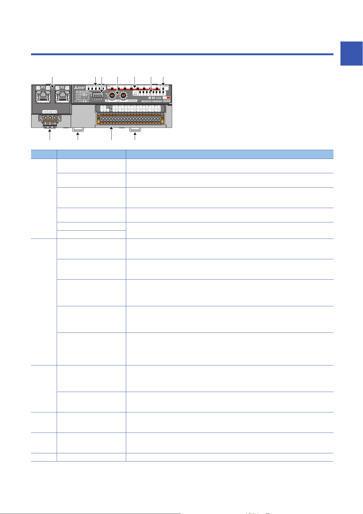
1 PART NAMES
(1) (2) (6) (7) (3)
(8) (10)(9) (9)
(4) (5)
This section describes part names of the IO-Link module.
No. Name Application
(1) P1 PORT1 connector for CC-Link IE Field Network (RJ45 connector)
L ER LED • On: Module received abnormal data, or module performing loopback
LINK LED Indicates the link status
P2 PORT2 connector for CC-Link IE Field Network (RJ45 connector)
L ER LED (Same as the LEDs of P1 connector)
LINK LED
(2) PW LED Indicates the power supply status of the IO-Link module.
RUN LED Indicates the operating status of the IO-Link module.
MODE LED Indicates the mode of the IO-Link module.
D LINK LED Indicates the data link status of the IO-Link module.
ERR. LED Indicates the error status of the IO-Link module.
(3) CH1 to CH8 LED (green) Indicates the operating status of each channel in IO-Link mode.
CH1 to CH8 LED (yellow) Indicates on/off of input or output for each channel in SIO mode
(4) CH1 to CH8 ERR. LED Indicates the error status of each channel in IO-Link mode or SIO mode.
(5) I/O PW LED Indicates the status of the power supply from the external power supply.
(6) Function setting switch A switch for the fast link-up function ( Page 30 Function setting switch setting)
An Ethernet cable is connected. ( Page 37 Wiring of Ethernet cable)
• Off: Module received normal data, or module not performing loopback
• On: Link-up in progress
• Off: Link-down in progress
An Ethernet cable is connected. ( Page 37 Wiring of Ethernet cable)
• On: Power supply ON
• Off: Power supply OFF
• On: Operating normally
• Off: A major error has occurred.
• On: Online mode
• Flashing: Unit test mode
• Off: In offline mode, or the unit test is completed.
• On: Data link in operation (cyclic transmission in progress)
• Flashing: Data link in operation (cyclic transmission stopped)
• Off: Data link not performed (disconnected or in unit test mode)
• On: A moderate or major error has occurred.
• Flashing: A minor error has occurred.
• Off: Operating normally
When a major error has been occurred, check RUN LED as well.
• On: Normal IO-Link communications
• Flashing: IO-Link communication error
• Off: Other than IO-Link mode
• On: I/O is on.
• Off: I/O is off.
• On: Channel error
• Off: Channels operating normally
• On: External power supply ON
• Off: External power supply OFF
*1
1
1 PART NAMES
13
Page 16

No. Name Application
(7) Station number setting switch A rotary switch for setting station numbers and used for unit tests.
(8) Terminal block for module power
supply and FG
(9) DIN rail hook A hook to mount an IO-Link module on a DIN rail
(10) IO-Link terminal block A terminal block to connect the external power supply and an external device
*1 IO-Link communication errors will occur if input process data and output process data are invalid. ( Page 156 Input process data,
Page 159 Output process data)
• Page 29 Setting station number setting switches
• Page 124 Unit Test
A terminal block to connect the module power supply (24VDC) and FG
14
1 PART NAMES
Page 17

2 SPECIFICATIONS
This chapter describes the specifications of the IO-Link module.
2.1 General Specifications
Item Specifications
Operating ambient
temperature
Storage ambient
temperature
Operating ambient
humidity
Storage ambient
humidity
Vibration resistance Compliant with JIS
Shock resistance Compliant with JIS B 3502 and IEC 61131-2 (147m/, 3 times each in X, Y, and Z directions)
Operating
atmosphere
Operating altitude
Installation location Inside a control panel
Overvoltage
*3
category
Pollution degree
Equipment class Class
*1 Do not use or store the IO-Link module under pressure higher than the atmospheric pressure of altitude 0m. Doing so may cause
malfunction. When using the IO-Link module under pressure, please consult your local Mitsubishi representative.
*2 If the environment satisfies the operating ambient temperature, operating ambient humidity and other conditions, the module can be
used even outside the control panel.
*3 This indicates the section of the power supply to which the equipment is assumed to be connected between the public electrical power
distribution network and the machinery within premises.
Category applies to equipment for which electrical power is supplied from fixed facilities. The surge voltage withstand level for up to
the rated voltage of 300V is 2500V.
*4 This index indicates the degree to which conductive material is generated in terms of the environment in which the equipment is used.
Pollution degree 2 is when only non-conductive pollution occurs. A temporary conductivity caused by condensing must be expected
occasionally.
*5 Use the special coated products which comply with the IEC 60721-3-3 3C2 in the environment with the corrosive gases. For details on
the special coated products, please consult your local representative.
*6 When the programmable controller is used at altitude above 2000m, the withstand voltage performance and the upper limit of the
operating ambient temperature decrease. Please consult your local Mitsubishi representative.
0 to 55
-25 to 75
5 to 95%RH, non-condensing
B 3502 and IEC
61131-2
No corrosive gases
*1
*4
0 to 2000m
or less
2 or less
*6
Frequency Constant
Under intermittent
vibration
Under continuous
vibration
*5
, flammable gases, less conductive dust
*2
5 to 8.4Hz 3.5mm 10 times each in X,
8.4 to 150Hz 9.8m/
5 to 8.4Hz 1.75mm
8.4 to 150Hz 4.9m/
acceleration
Half amplitude Sweep count
Y, and Z directions
2
To use the IO-Link module complying with the EMC Directive, refer to "EMC and Low Voltage Directives" in
this manual. ( Page 193 EMC and Low Voltage Directives)
2 SPECIFICATIONS
2.1 General Specifications
15
Page 18

2.2 Performance Specifications
NZ2GF2S-60IOLD8 IO-Link module
Item NZ2GF2S-60IOLD8
Module type CC-Link IE Field Network Intelligent device station
IO-Link IO-Link master
Rated input voltage 24VDC (ripple rate: 5% or less)
(allowable voltage range 20.4 to 28.8VDC (24VDC -15 to +20%))
Insulation method Between I/O and power supply Digital isolator
Between channels None
Withstand voltage 500VDC for 1 minute between all DC external terminals and the ground
Insulation resistance 10M or higher between all DC external terminals and ground (500VDC
Noise immunity Noise voltage 500Vp-p, noise width 1s, noise frequency 25 to 60Hz (DC type
Protection degree IP2X
Wiring method for common 8 points/common
Surge suppressor Zener diode
Fuse None
Protection function C/Q Overcurrent, overload protection
L+ Overcurrent
External interface CC-Link IE Field Network part RJ45 connector
Module power supply part Terminal block for module power supply and FG (spring clamp terminal block
IO-Link part 40-point 2-piece spring clamp terminal block (push-in type)
Module operation start
*4
time
Applicable DIN rail TH35-7.5Fe, TH35-7.5Al (compliant with IEC 60715)
Applicable wire size Terminal block for module power supply and FG Core: 0.5 to 2.0 (20 to 14 AWG), terminal slot size: 2.8mm 2.0mm
Applicable solderless
terminal
Operation mode The following 6 modes are available.
IO-Link mode Supported protocol v1.1.2
Cyclic transmission RX/RY points 48 points
IO-Link mode
SIO mode • 1 channel: 0.2 seconds
IO-Link terminal block ■For +24V/24G/FG
Terminal block for module power supply and FG
IO-Link terminal block
Number of channels 8 channels max.
Rated load current (C/Q) 200mA/channel, 4A/common
Rated load current (L+) 1.6A/channel, 4A/common
Transmission speed • COM1: 4.8kbps
IO-Link mode Compliant with IO-Link standard
RWr/RWw points 132 points
*5
*1*3
insulation resistance tester)
noise simulator condition)
(push-in type))
• 1 channel: 1.5 to 4 seconds
• 8 channels: 12 to 32 seconds
• 8 channels: 0.2 seconds
Core: 0.5 to 1.5 (20 to 16 AWG), terminal slot size: 2.4mm 1.5mm
■For CQ/L+/L-/DI
Core: 0.2 to 1.5 (24 to 16 AWG), terminal slot size: 2.4mm 1.5mm
*1
Page 35 Applicable solderless terminal
Page 39 Applicable solderless terminal
• Disabled mode
• IO-Link (standard) mode
• IO-Link (sink input) mode
• SIO (sink input) mode
• SIO (source output) mode
• Power supply mode
• COM2: 38.4kbps
• COM3: 230.4kbps
Determined by the IO-Link device connected. The transmission speed is
switched automatically.
16
2 SPECIFICATIONS
2.2 Performance Specifications
Page 19

Item NZ2GF2S-60IOLD8
IO-Link (sink input)
mode
SIO (sink input) mode Number of channels 8 channels max.
SIO (source output)
mode
IO-Link cable Cable type Unshielded
Communication cable An Ethernet cable that meets the 1000BASE-T standard:
Module power supply Voltage 24VDC (ripple rate: 5% or less)
External power supply Voltage 24VDC (ripple rate: 5% or less)
Weight 0.24kg
Number of channels 8 channels max.
Rated input current 2.5mA TYP. (for 24VDC)
Input response time • 0ms
ON voltage/ON current 12VDC or more/2mA or more
OFF voltage/OFF current 6VDC or less/2mA or less
Rated input current 2.4mA TYP. (for 24VDC)
Input response time
ON voltage/ON current 11VDC or more/2mA or more
OFF voltage/OFF current 6VDC or less/2mA or less
Number of channels 8 channels max.
Rated load current 200mA/point, 4A/common
Maximum inrush current 650mA 100s or less
Leakage current at OFF 0.1mA or less
Maximum voltage drop at ON 0.88V or less, 0.2mA
Cable length 20m maximum
Cable diameter Core 0.2 to 1.5
Current 130mA (24VDC, all points ON)
Protection function None
Fuse None
Current 95mA or less (24VDC, all points ON)
Protection function None
Fuse None
*2
•1ms
•1.5ms
•5ms
• 10ms (default value)
•20ms
•70ms
•0ms
•1ms
•1.5ms
•5ms
• 10ms (default value)
•20ms
•70ms
Category 5e or higher (double shielded, STP), straight cable
(allowable voltage range 20.4 to 28.8VDC (24VDC -15 to +20%))
(allowable voltage range 20.4 to 28.8VDC (24VDC -15 to +20%))
*1 Only one wire can be connected to a terminal. Multiple wires cannot be connected to a terminal. Connecting two or more wires may
cause a poor contact.
*2 For details on the input response time, refer to the following.
Page 192 Processing Time
*3 Use cables suitable for the current value used.
*4 The time taken for data link establishment with the master station at power-on is not included.
*5 The module operation start time written is a rough standard. The time depends on the response performance and data storage size of
the IO-Link device. In addition, because the start processing is performed for each channel, it takes longer time to start operation of the
module as the number of channels of which operation mode is set to IO-Link mode increases.
2
2 SPECIFICATIONS
2.2 Performance Specifications
17
Page 20
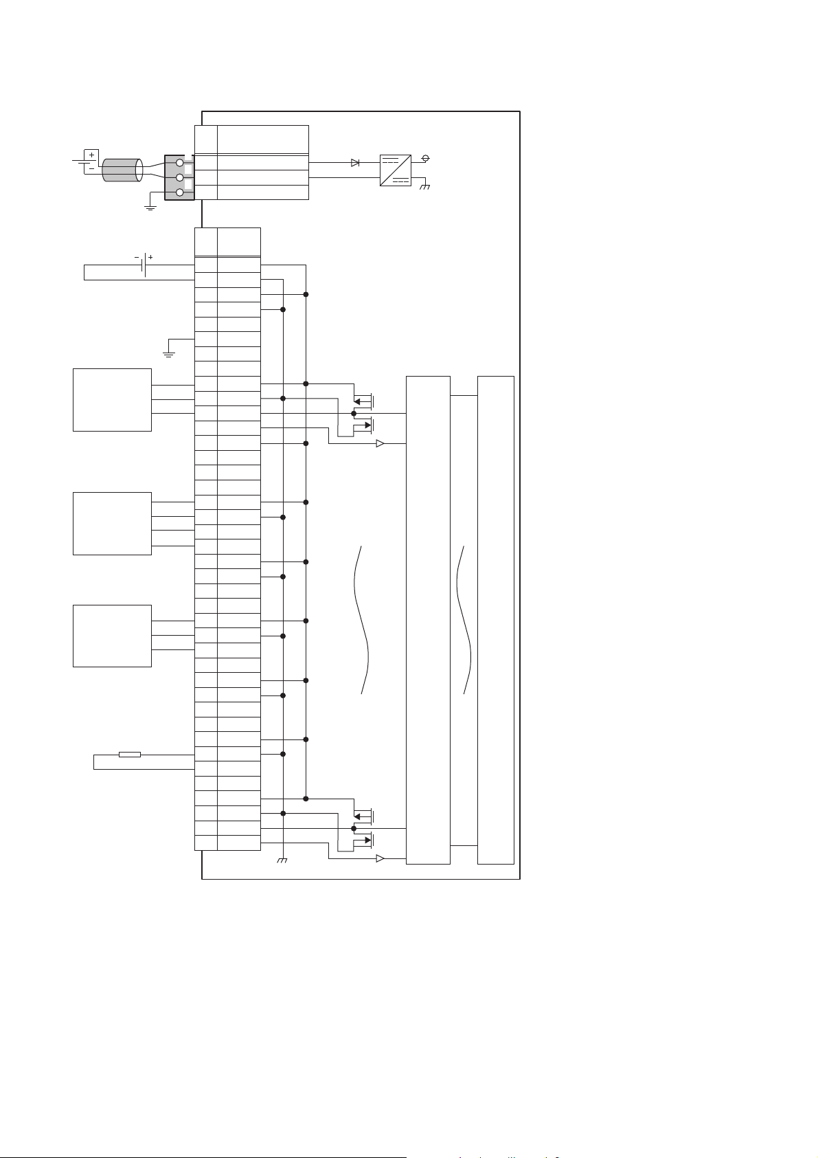
■External connection
FG
1
2
3
UNIT POWER
CABLE
1
2
3
+24V1
24G2
+24V3
24G4
NC5
FG6
7
NC8
L1+9
L1-10
CQ111
DI112
L2+13
L2-14
CQ215
DI216
L3+17
L3-18
CQ319
DI320
L4+21
L4-22
CQ423
DI424
L5+25
L5-26
CQ527
DI528
L6+29
L6-30
CQ631
DI632
L7+33
L7-34
CQ735
DI736
L8+37
L8-38
CQ839
DI840
+24V
*1
24G
NC
Signal
name
Pin
No.
Signal
name
Pin
No.
Non-insulated
IO-Link device
(IO-Link sensor)
SIO input
device (3-wire
sensor (PNP)
in SIO mode)
IO-Link device
(IO-Link sensor
(DI supported))
Module power
supply
IO-Link
terminal block
Terminal block for module
power supply and FG
Insulated
Digital
isolator
Internal
circuit
Load
External power supply
*1 Only one wire can be connected to a terminal of the terminal block for module power supply and FG. Multiple wires cannot be connected
18
to a terminal. Connecting two or more wires may cause a poor contact.
2 SPECIFICATIONS
2.2 Performance Specifications
Page 21
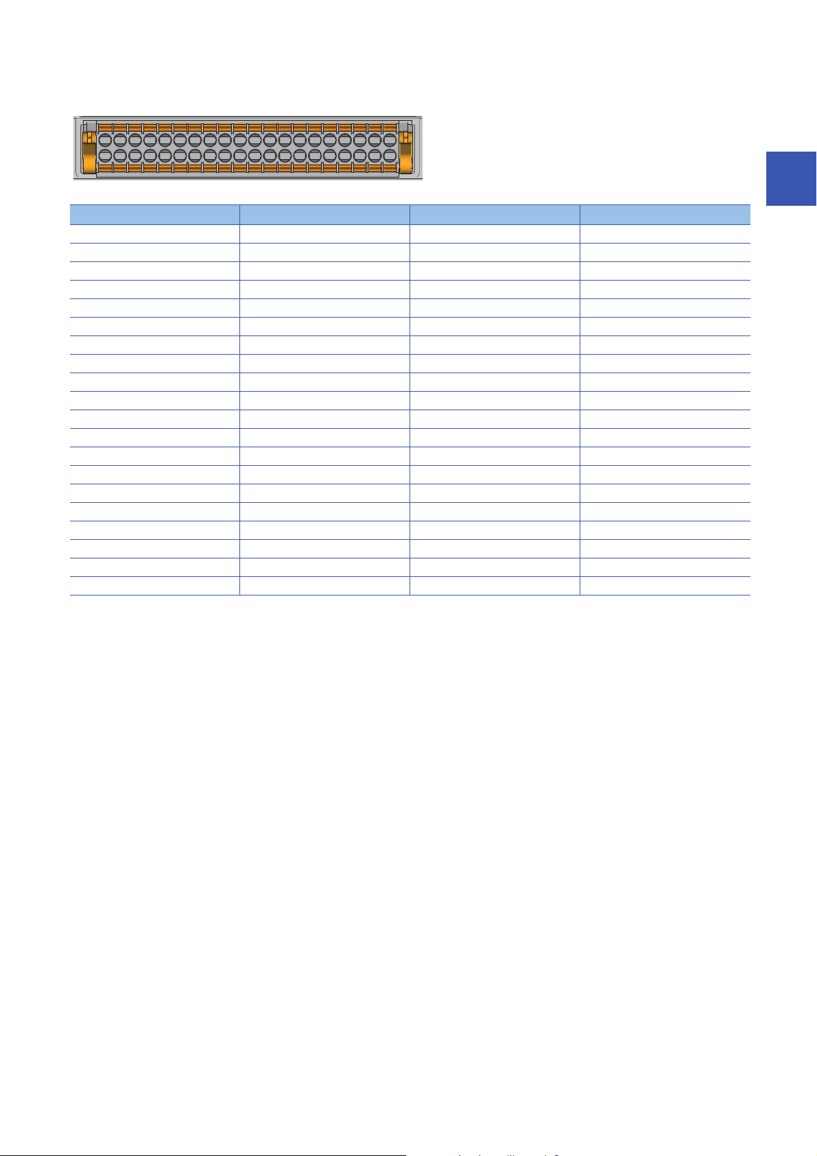
■IO-Link terminal block
3517 9 11 13 15 17 19 21 23 25 27 29 31 33 35 37 39
2
4 6 8 10 12 14 16 18 20 22 24 26 28 30 32 34 36 38 40
Pin number Signal name Pin number Signal name
1 +24V 21 L4+
2 24G 22 L4-
3 +24V 23 CQ4
4 24G 24 DI4
5NC25L5+
6FG26L5-
7NC27CQ5
8NC28DI5
9 L1+ 29 L6+
10 L1- 30 L6-
11 CQ 1 31 CQ 6
12 DI1 32 DI6
13 L2+ 33 L7+
14 L2- 34 L7-
15 CQ2 35 CQ7
16 DI2 36 DI7
17 L3+ 37 L8+
18 L3- 38 L8-
19 CQ3 39 CQ8
20 DI3 40 DI8
2
2 SPECIFICATIONS
2.2 Performance Specifications
19
Page 22

Function list
This section lists the functions of IO-Link modules.
IO-Link master functions
Item Description Reference
IO-Link cyclic transmission function Communicates process data periodically with the IO-Link device
connected to each channel.
IO-Link transient communication function Reads/writes parameters at any timing from/to the IO-Link device
connected to each channel.
IO-Link device setting automatic upload/
download function
IO-Link device validation function Validates compatibility and identity of the IO-Link device connected to
Disconnection detection function Detects disconnection if communication with an IO-Link device is lost in
Input data masking function Calculates ON/OFF values in IO-Link (standard) mode according to the
Swap function Swaps the upper and lower bytes of data sent and received between
Bit segment function Segments input process data using the bit count set for each channel. Page 78 Bit segment function
IO-Link communication retry count integration
function
Saves the parameters of the IO-Link device connected to each channel
in the IO-Link module, and as necessary, overwrites the parameters of
the IO-Link devices.
each channel.
IO-Link mode.
input process data.
the IO-Link module and the IO-Link device connected to each channel.
Counts the number of IO-Link communication retries for each channel Page 81 IO-Link communication
Page 64 IO-Link cyclic
transmission function
Page 66 IO-Link transient
communication function
Page 67 IO-Link device setting
automatic upload/download
function
Page 70 IO-Link device validation
function
Page 73 Disconnection detection
function
Page 74 Input data masking
function
Page 76 Swap function
retry count integration function
Input function
Item Description Reference
Input OFF delay function This function turns off an X signal after a predetermined time passed
from when an actual input becomes off from on.
Input response time setting function This function prevents an incorrect input due to noise by setting the
response time until the module recognizes an actual input as the X
signal.
Page 83 Input OFF delay function
Page 85 Input response time
setting function
Output function
Item Description Reference
Number of output ON times integration function The number of ON times of each output point is counted within the
range of 0 to 2147483647.
Output ON/OFF information hold function This function checks if the output has been turned once on or off. Page 88 Output ON/OFF
Page 87 Number of output ON
times integration function
information hold function
20
2 SPECIFICATIONS
2.2 Performance Specifications
Page 23

CC-Link IE Field Network communication function
Item Description Reference
Cyclic transmission Periodically exchanges data among stations on the network using link
devices. An IO-Link module operates as an intelligent device station on
the CC-Link IE Field Network.
Transient transmission Reads or writes data on the IO-Link module in line with a dedicated
instruction from the master station.
The IO-Link module uses the REMFR instruction or REMTO instruction
to perform transient transmission.
Fast link-up function Shortens the time taken for data link establishment with the master
station at power-on.
Output HOLD/CLEAR setting function Whether to hold or clear the last SIO output and output process data
can be set when the IO-Link module is disconnected from data link or
when the CPU module operating status is STOP.
Page 89 Cyclic transmission
Page 90 Transient transmission
Page 91 Fast link-up function
Page 94 Output HOLD/CLEAR
setting function
Others
Item Description Reference
Event acquisition function Notifies of IO-Link device events upon sending of event data from the
IO-Link device to the IO-Link module.
Protection function Protects internal circuits from overcurrent and its heat using an
overload protection function and overheat protection function.
External power supply monitoring function Monitors the ON/OFF status of the external power supplies of IO-Link
modules.
Device replacement function Enables device replacement when the IO-Link module power supply is
on.
Page 96 Event Acquisition
Function
Page 97 Protection Function
Page 98 External Power Supply
Monitoring Function
Page 99 Device Replacement
Function
2
2 SPECIFICATIONS
2.2 Performance Specifications
21
Page 24

3 PROCEDURES BEFORE OPERATION
This chapter describes the procedures before operation.
1. Station number setting
Set the IO-Link module station number.
Page 29 Setting station number setting switches
2. Function setting switch setting
Set the function setting switch.
Page 30 Function setting switch setting
3. Connection
Mount the IO-Link module on the DIN rail.
Page 33 Mounting the modules on a DIN rail
4. Wiring
Wire a power supply, an Ethernet cable, and an external device to the IO-Link module.
Page 35 Wiring with terminal block for module power supply and FG
Page 37 Wiring of Ethernet cable
Page 39 Wiring of IO-Link terminal block and external devices
5. Power-on
Power on the IO-Link module.
6. Parameter setting and programming
Set parameters and create a program.
Page 43 PARAMETER SETTING
Page 105 PROGRAMMING
To replace the IO-Link module, follow the procedure described below.
• Power off the IO-Link module and remove it.
• Prepare a new IO-Link module and perform the above procedure. (The network parameters of the CC-Link
IE Field Network master station do not need to be set again.)
• After checking the operation, restart the control.
22
3 PROCEDURES BEFORE OPERATION
Page 25

MEMO
3
3 PROCEDURES BEFORE OPERATION
23
Page 26
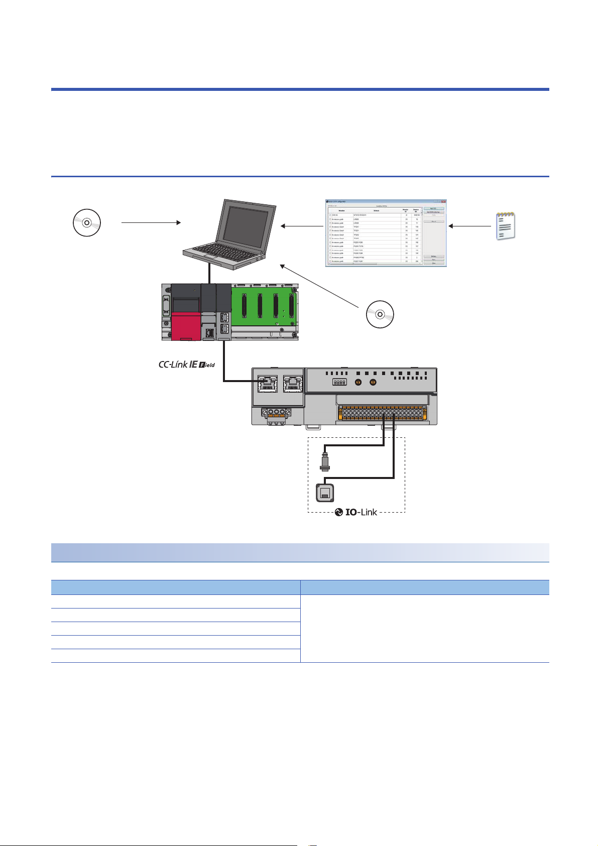
4 SYSTEM CONFIGURATION
NZ2GF2S-60IOLD8
(1)
DeviceDTM
M_CommDTM-IOLink
IODD DTM Configurator
IODD
This chapter describes system configuration using an IO-Link module.
For CC-Link IE Field Network configuration, refer to the following.
User's manual for the master/local module used
4.1 Applicable Systems
(1) Personal computer (engineering tool/FDC)
Applicable master station
When using an IO-Link module, use the following products as a master station.
Model
RJ71GF11-T2 No restriction
RJ71EN71
R04ENCPU, R08ENCPU, R16ENCPU, R32ENCPU, R120ENCPU
QJ71GF11-T2
LJ71GF11-T2
*1 Simple motion modules and interface boards compatible with the CC-Link IE Field Network cannot be used.
Information on "Applicable master station" described above is the ones at the point when this manual was issued.
For latest information, please visit the website of CC-Link Partner Association.
www.cc-link.org
24
*1
4 SYSTEM CONFIGURATION
4.1 Applicable Systems
First five digits of serial number
Page 27

Ethernet cable
For the specifications of the Ethernet cable, refer to the following.
User's manual for the master/local module used
IO-Link cable
For details on IO-Link cables, refer to the following.
Page 35 Wiring with terminal block for module power supply and FG
Available software
The following software is available for settings and diagnostics of the IO-Link module. ( Manuals of each software)
Product name Functions/applications
GX Works2 Software for system design, programming, debugging, and maintenance of the programmable controller.
GX Works3
MELSOFT Navigator Integrated application of GX Works2 and GX Works3.
FDC Application for DTM.
M_CommDTM-IOLink
IODD DTM Configurator
When the latest software is required, please consult your local Mitsubishi representative.
Applicable profile
To use the parameter setting function of an IO-Link module, the profile is required.
The profile is a setting file that stores information required for the start-up, operation, and maintenance of devices supporting
the CC-Link family.
A module is added to "Module List" of the "CC IE Field Configuration" window by profile registration to an engineering tool. For
the profile registration, refer to the operating manual for the engineering tool used.
4
Applicable devices
Up to eight IO-Link devices and SIO devices can be connected in combination to the IO-Link module.
The IO-Link mode and SIO mode can be set separately on the channels of the IO-Link module.
Refer to the following for operation modes supported by connected external devices.
Operation mode Description
Disabled mode Select this mode when no devices are connected.
An error is not detected when a channel in disabled mode is operating.
IO-Link (standard) mode Select this mode to communicate with IO-Link devices. Process data is sent
and received at the following communication speeds.
• COM1: 4.8kbps
• COM2: 38.4kbps
• COM3: 230.4kbps
IO-Link (sink input) mode Select this mode to connect a source-type IO-Link device. In addition to IO-
SIO (sink input) mode Select this mode to connect a source-type SIO (input) device. This mode
SIO (source output) mode Select this mode to connect a sink-type SIO (output) device. This mode
Power supply mode Select this mode to supply power to the device of another channel.
Link (standard) mode, digital input is also supported.
communicates with general devices and supports digital input.
communicates with general devices and supports digital input.
An error in the power line is only detected when a channel in power supply
mode is operating.
For setting examples and wiring methods, refer to the following.
Page 42 Using IO-Link devices that require power supplies for their
multiple terminals
For error codes and warning codes detectable in each operation mode, refer to the following.
Page 134 List of error codes and the warning codes
4 SYSTEM CONFIGURATION
4.1 Applicable Systems
25
Page 28
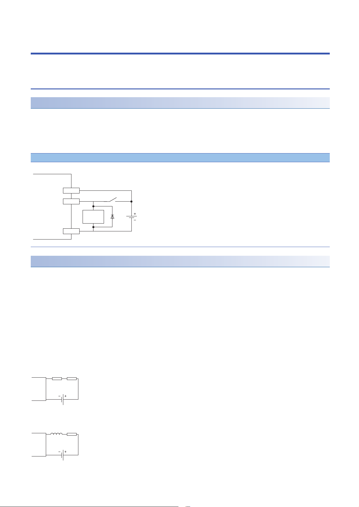
5 INSTALLATION AND WIRING
24G
CQ
+24V
Sink input
IO-Link module
Inductive
load
Resistor Load
IO-Link
module
Load
IO-Link
module
Inductor
This section describes the installation and wiring of the IO-Link module.
5.1 Before Using the I/O Link Module
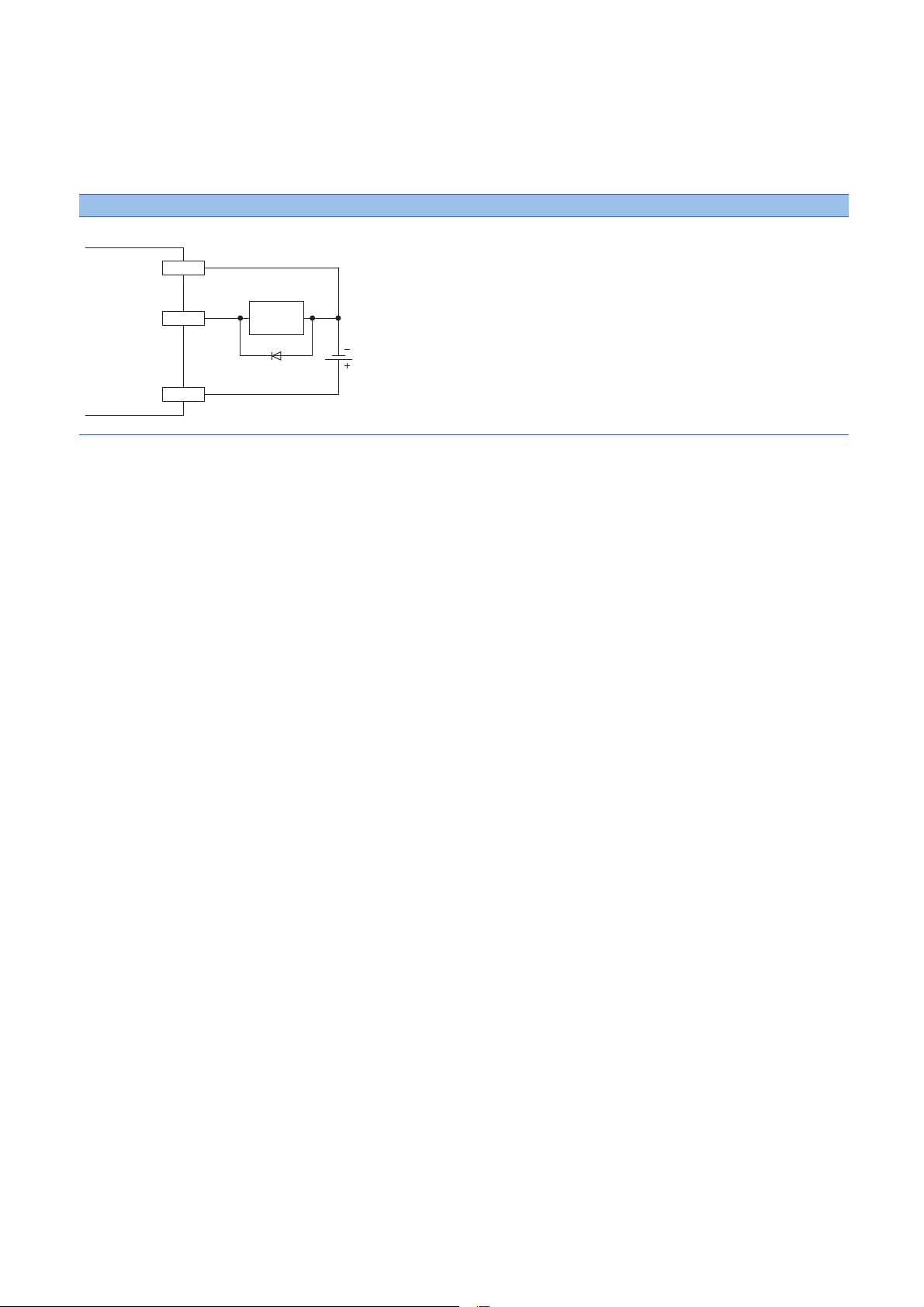
Precautions when using SIO (sink input) mode
■Measures against back EMF
When connecting an inductive load, connect a diode in parallel with the load. Use the diode that satisfies the following
conditions:
• A reverse breakdown voltage is ten times as high as the circuit voltage or more.
• A forward current is twice as high as the load current or more.
SIO (sink input)
Precautions when using SIO (source output) mode
■Maximum switching frequency when L load is driven
The maximum switching frequency imposes a limit on the use; an ON state or an OFF state must not be changed without an
interval of at least one second.
■Load to be connected
When connecting a counter or timer utilizing a DC/DC converter as a load of the IO-Link module, select an IO-Link module
whose maximum load current is higher than the inrush current of a load to be connected. If the selection is based on the
average current of a load to be connected, an inrush current flows cyclically from the load while the IO-Link module is in an
ON state or in operation, which can cause failure of the module. If it is necessary to select a module on the basis of the
average current of a load to be connected, to alleviate the effect of the inrush current, take any of the following corrective
actions:
• Connecting a resistor in series with the load
• Connecting an inductor in series with the load
26
5 INSTALLATION AND WIRING
5.1 Before Using the I/O Link Module
Page 29
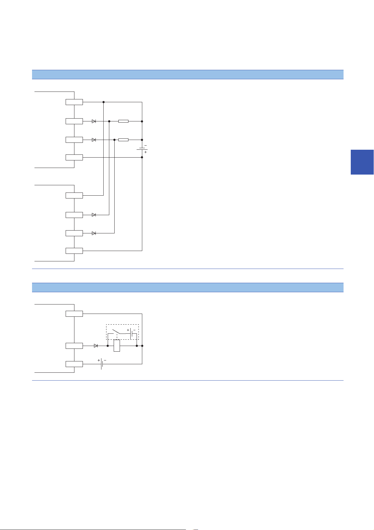
■Measures against reverse current
24G
+24V
CQ1
CQ2
24G
+24V
CQ1
CQ2
Load
IO-Link module
IO-Link module
Load
+24V
CQ
24G
IO-Link module
Additional circuit
In the following connections, a reverse current flows to the output element, which can cause failure.
When wiring, set up diodes as the following figures show:
• When connecting IO-Link modules in parallel
Source type
5
• When providing another circuit in parallel with an IO-Link module
Source type
5 INSTALLATION AND WIRING
5.1 Before Using the I/O Link Module
27
Page 30
■Measures against back EMF
+24V
CQ
24G
IO-Link module
Inductive
load
When connecting an inductive load, connect a diode in parallel with the load.
Use the diode that satisfies the following conditions:
• A reverse breakdown voltage is ten times as high as the circuit voltage or more.
• A forward current is twice as high as the load current or more.
Source type
■About element protection of the IO-Link module
If excessive noise affects the terminals of the IO-Link module, the output may be turned on to help the protection of the output
element. Adjust the voltage between terminals of the IO-Link module to fall within the operating load voltage range by taking
measures such as the following:
• To use an inductive load such as a relay, a surge suppressor is required on the load side as well. Take appropriate
measures, referring to the measures against back EMF as a guide.
• To prevent excessive noise, avoid installing power cables together with I/O cables.
28
5 INSTALLATION AND WIRING
5.1 Before Using the I/O Link Module
Page 31

5.2 Setting Switch
Ex.
Setting station number setting switches
Setting procedure
Set the station number using the rotary switches on the front of the IO-Link module. The set value of the station number
becomes valid when the module is powered on. Thus, set the station number while the module power is off.
• The hundreds and tens places of the station number are set with 10.
• The ones place of the station number is set with 1.
To set the station number setting switches, use a flathead screwdriver with a tip width of 3.5mm or less.
To set the station number to 115, set the switches as shown below.
5
Setting range
Set the station number from 1 to 120. Setting the value other than 1 to 120 causes a communication error and the D LINK
LED flashes.
Do not set a station number duplicated with other station numbers. If the station number is duplicated, a
communication error occurs and the D LINK LED does not turn on.
5 INSTALLATION AND WIRING
5.2 Setting Switch
29
Page 32

Function setting switch setting
Enable or disable the fast link-up function using the function setting switches on the front of the IO-Link module. The setting
made by the function setting switches becomes valid when the module is powered on. Thus, set these switches while the
module power is off.
For details on the fast link-up function, refer to the following.
Page 91 Fast link-up function
No. Switch name Function name Setting details
1 Function setting switch 1
(F LINK P1)
2 Function setting switch 2
(F LINK P2)
3 Use prohibited Always set to Off.
4
PORT1 fast link-up function Enables or disables the fast link-up function of PORT1.
• On: Enable
• Off: Disable
PORT2 fast link-up function Enables or disables the fast link-up function of PORT2.
• On: Enable
• Off: Disable
• To set the function setting switches, use a flathead screwdriver with a tip width of 0.9mm or less.
• Do not change the function setting switch while the module is powered on. Changing the function setting
switch while the module is powered on causes a minor error and flashes the ERR. LED. Returning the
function setting switch to the previous setting eliminates the error and turns off the ERR. LED.
30
5 INSTALLATION AND WIRING
5.2 Setting Switch
Page 33

5.3 Installation Environment and Installation Position
(1) (1)(1)
(1) (1)
(1) (1)
Installation environment
Installation location
Do not install the IO-Link module to the place under the following condition.
• Ambient temperature is outside the range from 0 to 55;
• Ambient humidity is outside the range from 5 to 95%RH;
• Condensation occurs due to rapid temperature change;
• Corrosive gas or combustible gas is present;
• Conductive powder such as dust and iron powder, oil mist, salinity, or organic solvent is filled;
• The I/O module is exposed to direct sunlight;
• A strong electric field or strong magnetic field is generated; and
• The I/O module is subject to vibration and shock.
Installation surface
Install the IO-Link module on the flat surface. When the installation surface is uneven, excessive force is applied to the
printed-circuit board and may cause a defect.
Installation position
5
When installing the IO-Link module in a control panel, provide clearance of at least 60mm (1) between the IO-Link module and
the sides of the control panel or neighboring modules to ensure good ventilation and easy IO-Link module replacement.
5 INSTALLATION AND WIRING
5.3 Installation Environment and Installation Position
31
Page 34

Installation direction
Downward installation
DIN rail
Vertical installation Horizontal installation Horizontal installation
(upside down)
Upward installation
The IO-Link module can be installed in six directions.
Use a DIN rail to install the IO-Link module.
32
5 INSTALLATION AND WIRING
5.3 Installation Environment and Installation Position
Page 35

5.4 Installation
Mounting the modules on a DIN rail
An example of the use of the DIN rail stopper is described in the following procedure. Fix the module
according to the manual of the DIN rail stopper used.
Mounting procedure
1. Pull down all DIN rail hooks on the back of the modules.
The levers should be pulled down until they click.
2. Hang the upper tabs of the modules on a DIN rail, and
5
push the modules in position.
3. Lock the DIN rail hooks to the DIN rail to secure the
modules in position.
Push each hook up until it clicks. If the hooks are beyond the
reach, use a tool such as a driver.
4. Loosen the screw on DIN rail stopper.
5. Hitch the bottom hook of the DIN rail stopper to the
bottom of the DIN rail.
Hitch the hook according to the orientation of the arrow on
the front of the stopper.
6. Hitch the upper hook of the DIN rail stopper to the top of
the DIN rail.
5 INSTALLATION AND WIRING
5.4 Installation
33
Page 36

7. Slide the DIN rail stopper up to the left side of the
modules.
8. Hold the DIN rail stopper in the direction opposite to the
arrow on the stopper and tighten the screw with a driver.
9. Install the DIN rail stopper on the right side of the
module in the same procedure.
Install the stopper upside down for the right side.
Do not slide modules from the edge of the DIN rail when mounting them. The modules may be damaged.
Removal procedure
Remove the modules from the DIN rail by reversing the above procedure.
Applicable DIN rail models (compliant with JIS C 2812/IEC 60715)
• TH35-7.5Fe
• TH35-7.5Al
Interval between DIN rail mounting screws
Tighten the screws at intervals of 200mm or less.
DIN rail stopper
Use a stopper that is attachable to the DIN rail.
34
5 INSTALLATION AND WIRING
5.4 Installation
Page 37

5.5 Wiring
Wiring with terminal block for module power supply and FG
Tightening torque
Tighten the terminal block mounting screws within the following specified torque range.
Tightening the screw too much may damage the IO-Link module case.
Screw type Tightening torque range
Terminal block mounting screw (M2.5 screw) 0.2 to 0.3Nm
Wire to be used
The following describes the wire to be connected to the terminal block for module power supply and FG.
Diameter Type Material Temperature rating
20 to 14 AWG Core Copper wire 75 or more
Applicable solderless terminal
The following table lists the applicable solderless terminal.
Product name Model Applicable wire size Bar solderless terminal
tool
Bar solderless terminal AI 0.5-8WH, AI 0.5-10WH 0.5 CRIMPFOX6 PHOENIX CONTACT GmbH & Co. KG
AI 0.75-8GY, AI 0.75-10GY 0.75
AI 1-8RD, AI 1-10RD 1.0
AI 1.5-8BK, AI 1.5-10BK 1.5
Al 2.5-10BU 2.0
Contact
5
Installing and removing the terminal block
To remove the terminal block, loosen the terminal block mounting screw with a flathead screwdriver.
To install the terminal block, tighten the terminal block mounting screw with a flathead screwdriver.
Failure to secure the terminal block may cause drop, short circuit, or malfunction.
5 INSTALLATION AND WIRING
5.5 Wiring
35
Page 38

Connecting and disconnecting the cable
(1)
2.0mm
2.8mm
Insertion slot
To connect the cable, fully insert a wire having a bar solderless terminal into a wire insertion opening.
After inserting the wire, pull it lightly to check that it is securely clamped.
A continuity check can be conducted using a test terminal (1).
To disconnect the cable, push in the open/close button with a flathead screwdriver.
With the button pushed in, pull out the wire having a bar solderless terminal.
Precautions
• Use a bar solderless terminal for the wiring to the push-in type spring clamp terminal block. If a stripped wire is inserted into
a wire insertion opening, the wire cannot be securely clamped.
• For how long the wire should be stripped, follow the specifications of the bar solderless terminal used. To attach a bar
solderless terminal to a wire, use a crimping tool.
• Before inserting a bar solderless terminal into a wire insertion opening (1), check the shape of the opening and the shape of
the terminal. Insert the terminal paying attention to the orientation. If a bar solderless terminal larger than the wire insertion
opening (1) is inserted, the terminal block may be damaged.
• To comply with the EMC Directive, use a separate power supply for each of the module power supply and the external
power supply.
36
5 INSTALLATION AND WIRING
5.5 Wiring
Page 39

Wiring of Ethernet cable
Either one can be used.
Wiring method
■Installation method
1. Turn off the power supplies of the IO-Link module and the external device.
2. Push the Ethernet cable connector into the IO-Link module until it clicks. Pay attention to the direction of the connector.
3. Power on the IO-Link module.
4. Power on the external device.
5. Check if the LINK LED on the port into which the Ethernet cable is connected is on.
*1 The time taken for the LINK LED to turn on after connection of the cable may vary. The LINK LED normally turns on in a few seconds.
However, if link-up processing is repeated due to a condition of a device on the line, the longer time may be required. If the LINK LED
does not turn on, refer to the following and take a corrective action.
Page 123 When the LINK LED is off
• When the fast link-up function is not used, PORT1 and PORT2 connectors do not need to be distinguished.
When only one connector is used in star topology, either PORT1 or PORT2 can be connected. For how to
connect Ethernet cables for using the fast link-up function, refer to the following.
Page 91 Fast link-up function
* 1
5
• When two connectors are used in line topology or ring topology, an Ethernet cable can be connected to the
connectors in any combination. For example, the cable can be connected between PORT1s and between
PORT1 and PORT2.
Connection between
PORT1s or PORT2s
Connection between
PORT1 and PORT2
■How to disconnect
1. Turn off the power supply of the IO-Link module.
2. Press the latch down and unplug the Ethernet cable.
5 INSTALLATION AND WIRING
5.5 Wiring
37
Page 40

Precautions
■Laying Ethernet cables
• Place the Ethernet cable in a duct or clamp them. If not, dangling cable may swing or inadvertently be pulled, resulting in
damage to the module or cables or malfunction due to poor contact.
• Do not touch the core of the connector of the cable or the module, and protect it from dirt and dust. If any oil from your hand,
or any dirt or dust sticks to the core, it can increase transmission loss, causing data link to fail.
• Regarding the Ethernet cable to be used, check that the Ethernet cable has no disconnections or short circuits, or problems
in the connection of the connector.
■Broken cable latch
Do not use Ethernet cables with broken latches. Doing so may cause the cable to unplug or malfunction.
■Connecting and disconnecting the Ethernet cable
Hold the connector part when connecting and disconnecting the Ethernet cable. Pulling the cable connected to the module
may result in damage to the module or cable or malfunction due to poor contact.
■Connectors without Ethernet cable
To prevent dust from entering the module, attach the provided connector cover.
■Maximum station-to-station distance (Maximum Ethernet cable length)
The maximum station-to-station distance is 100m. However, the distance may be shorter depending on the operating
environment of the cable. For details, contact the manufacturer of the cables used.
■Bending radius of the Ethernet cable
There are restrictions on the bending radius of the Ethernet cable. Check the bending radius in the specifications of the
Ethernet cables used.
38
5 INSTALLATION AND WIRING
5.5 Wiring
Page 41

Wiring of IO-Link terminal block and external devices
Wire to be used
The following describes the wire to be connected to the IO-Link terminal block.
Diameter
■For +24V/24G/FG
20 to 16 AWG
■For CQ/L+/L-/DI
24 to 16 AWG
*1 Use cables suitable for the current value used.
Applicable solderless terminal
The following table lists the applicable solderless terminal.
Product name Model Applicable wire size Bar solderless terminal
Bar solderless terminal AI 0.34-8TQ 0.2 CRIMPFOX6 PHOENIX CONTACT GmbH & Co. KG
*1
A 0.5-10, AI 0.5-10WH 0.5
A 0.75-10, AI 0.75-10GY 0.75
A 1-10 1.0
A 1.5-10 1.5
Type Material Temperature rating
Core Copper wire 75 or more
Contact
tool
5
Installing and removing the terminal block
The following procedures show how to install and remove the terminal block.
■Lock and release lever positions
To make it easy to install and remove the terminal block, a three-stage positioning stopper is attached so that the lever does
not freely turn around.
When installing or removing the terminal block, turn the lever to the lock or release lever position.
Figure viewed from the module right surface: When pulling the terminal block
(2)
(1)
Figure viewed from the module right surface: When insertion of the terminal
block has completed
(1)
1. Release lever position
This lever position shows the state in which the terminal
block (1) has been completely pulled out from the module.
Turn the lever from the locking position to the release
position (2) to lift the terminal block from the IO-Link module.
2. Lock lever position
This position shows the state in which the terminal block (1)
completely fits the module.
Check the lock lever position (2) and pull the terminal block
lightly to confirm that the module completely fits the terminal
block.
(2)
5 INSTALLATION AND WIRING
5.5 Wiring
39
Page 42

■Removal procedure
(1)
(2)
1.5mm
(1.8mm)
(2.4mm)
R1.2mm
Cross-sectional shape of
bar solderless terminal
Turn the lever to the release lever position and remove the terminal block from the module.
■Installation procedure
Move the lever to the locking lever position and push the terminal block. If the terminal block is fully pushed in, the hook of the
lever hangs on the module and fits the terminal block.
The terminal block can be inserted with the lever locations other than the lock lever position.
After insertion, check that the lever is in the lock lever position.
Connecting and disconnecting the cable
■Connecting the cable
Insert wire in which the tip thereof has been processed into a wire insertion opening (2) and push it to the back.
If the wire cannot be inserted by this method, insert the wire completely while holding down the release button (1) using a
flathead screwdriver with a tip width of 2.0 to 2.5mm. Once the wire is inserted to the back, remove the screwdriver.
■Disconnecting the cable
Pull out the wire while holding down the release button using a flathead screwdriver with a tip width of 2.0 to 2.5mm.
■Precautions
• Use a crimping tool to connect a bar solderless terminal to a wire. ( Page 39 Applicable solderless terminal)
• The maximum station-to-station distance of IO-Link cables is 20m. However, the distance may be shorter depending on the
operating environment of the cables. For details, contact the manufacturer of the cables used.
• When inserting a bar solderless terminal, check that the size of the terminal and its insertion direction are correct to prevent
the terminal from getting stuck in or the terminal block damage. When using a bar solderless terminal other than the
applicable solderless terminals, check that the cross-sectional shape of the terminal after processing (the size includes an
error in processing) is smaller than the size mentioned below. For the correct terminal insertion direction, refer to the figure
below.
40
5 INSTALLATION AND WIRING
5.5 Wiring
Page 43

For details on the finish shape of a bar solderless terminal including an error in processing, contact the
L+
Pin1
(1)
Pin4
Pin3
CQ
L-DI
L+
Pin1
(1)
Pin4
Pin3
CQ
L-DI
Pin2
L+
Pin1
(1)
Pin4
Pin3
CQ
L-DI
manufacturers of the bar solderless terminal and the crimping tool.
Signal names of the terminal block
The following table shows signal names of the terminal block.
IN OUT FG CH1 CH2 CH3 CH4 CH5 CH6 CH7 CH8
+24V +24V NC NC L1+ CQ1 L2+ CQ2 L3+ CQ3 L4+ CQ4 L5+ CQ5 L6+ CQ6 L7+ CQ7 L8+ CQ8
24G 24G FG NC L1- Dl1 L2- Dl2 L3- Dl3 L4- Dl4 L5- Dl5 L6- Dl6 L7- Dl7 L8- Dl8
Wiring to the terminal block
The following figures show wiring to the terminal block.
■IO-Link (standard) mode wiring
(1) IO-Link device (IO-Link sensor)
1 to 8
Pin 1: Brown
Pin 3: Blue
Pin 4: Black
■IO-Link (sink input) mode wiring
5
(1) IO-Link device (IO-Link sensor (DI support))
1 to 8
Pin 1: Brown
Pin 2: White
Pin 3: Blue
Pin 4: Black
■SIO (sink input) mode wiring
(1) SIO input device (SIO mode 3-wire sensor (PNP))
1 to 8
5 INSTALLATION AND WIRING
5.5 Wiring
41
Page 44

■SIO (source output) mode wiring
Ex.
L+
Pin4
Pin3
CQ
L-DI
Load
L1+
Pin1
(1)
Pin4
Pin3
PinA
CQ1
L1- DI1
L2+ CQ2
L2- DI2
1 to 8
■Using IO-Link devices that require power supplies for their multiple terminals
Some models of IO-Link device require power supplies for their multiple terminals.
Using IO-Link devices that require power supplies for two terminals
(1) IO-Link device
Pin 1: L+ (1st 24VDC)
Pin A: L+ (2nd 24VDC)
L+ of CH2 supplies power to Pin A.
Operation modes at this times are as follows.
• CH1: IO-Link (standard) mode
• CH2: Power supply mode
42
5 INSTALLATION AND WIRING
5.5 Wiring
Page 45

6 PARAMETER SETTING
Operating procedure
(1)
(2)
This chapter describes the procedure for setting parameters of the IO-Link module.
6.1 CC-Link IE Field Network Parameter Setting
Set the parameter of the IO-Link module with the network parameter written to the CPU module of the CC-Link IE Field
Network master station. For details on setting the CC-Link IE Field Network master station, refer to the following.
User's manual for the master/local module used
1. Open the "CC IE Field Configuration" window.
[Navigation window] [Parameter] [Module Information] [RJ71GF11-T2] [Basic Settings] [Network
Configuration Settings]
2. Select an IO-Link module from "Module List", and drag and drop it to the list of stations or the network map.
6
(1) List of stations
(2) Network map
3. Configure the IO-Link module settings.
Item Description
STA# Set the station number of a slave station to be connected to the network.
Station Type Automatically set to "Intelligent Device Station".
RX/RY Setting Set RX and RY assignment. Automatically set to 48 points for the IO-Link
RWw/RWr Setting Set RWw and RWr assignments. Automatically set to 132 points for the IO-
Reserved/Error Invalid Station/System Switching Monitoring Target Station Use this to set the slave station as an error invalid station or a switching
4. Close the "CC IE Field Configuration" window.
[CC IE Field Configuration] [Close with Reflecting the Setting]
The station number need not be a serial number. (Must not be overlapped.)
module.
Link module.
monitoring target station.
6 PARAMETER SETTING
6.1 CC-Link IE Field Network Parameter Setting
43
Page 46

Precautions
■Precautions before parameter settings
For the precautions before parameter settings, refer to the following.
GX Works3 Operating Manual
GX Works2 Version 1 Operating Manual (Common)
■Precautions for parameter settings
• When using the IO-Link module, always enable the station-based block data assurance. When it is disabled, correct
operation of the IO-Link module cannot be guaranteed. For details on the block data assurance per station, refer to the
following: User's manual for the master/local module used.
• Do not set the parameter using the CCPASET instruction in the master station. Correct operation of the IO-Link module
cannot be guaranteed because the module operates with the station-based block data assurance disabled when the
CCPASET instruction is executed. (The CCPASET instruction is intended to configure parameters for a master/local
module. For details on the CCPASET instruction, refer to the user's manual for the master/local module used.)
44
6 PARAMETER SETTING
6.1 CC-Link IE Field Network Parameter Setting
Page 47

6.2 IO-Link Module Parameter Setting
Operating procedure
(1)
(2)
(3)
(4)
This section describes the procedure for setting parameters of IO-Link module via the engineering tool.
1. Open the "CC IE Field Configuration" window.
[Navigation window] [Parameter] [Module Information] [RJ71GF11-T2] [Basic Settings] [Network
Configuration Settings]
2. Open the "Parameter Processing of Slave Station" window.
From the list of stations, select an IO-Link module [CC IE Field Configuration] [Online] [Parameter Processing of
Slave Station].
3. Set "Method selection" to "Write Parameters".
4. Double-click the item to change the setting, and input the setting value.
Item Setting method
Items to input from the pull-down list Double-click the item to set, to display the pull-down list. Select the item.
Items to input from the text box Double-click the item to set, and input the setting value.
6
(1) Items to input from the drop-down list
(2) Checkbox
(3) The list cannot be collapsed.
(4) Items to input from the text box
6 PARAMETER SETTING
6.2 IO-Link Module Parameter Setting
45
Page 48

5. Click the [Execute Parameter Processing] button, and the following window is displayed.
Displayed items
6. Click the [Yes] button.
7. The parameters are written to the IO-Link module.
8. Select [Close with Reflecting the Setting] to exit the network configuration setting.
• To read the parameter from the IO-Link module, set "Method selection" to "Read Parameters" and click the
[Execute Parameter Processing] button.
• Set all the items for the parameter. If any blank exists, the parameters cannot be written to the IO-Link
module.
Setting item Reference
Individual Station Parameters Input Response Time Setting Page 85 Input response time setting
Output HOLD/CLEAR Setting Page 94 Output HOLD/CLEAR
Individual Module Parameters CH1 Operation Mode Page 25 Applicable devices
Device Validation Setting Page 70 IO-Link device validation
Input OFF Delay Setting Page 83 Input OFF delay function
Input Data Mask Page 74 Input data masking function
Byte Position Swap Page 76 Swap function
Event Retrieval Setting Notifications Page 96 Event Acquisition Function
Warnings
Bit Slicing Setting Number of Slicings Page 78 Bit segment function
No.1Bit Offset
No.1Bit Length
No.2Bit Offset
No.2Bit Length
No.15Bit Offset
No.15Bit Length
No.16Bit Offset
No.16Bit Length
Individual Module Parameters CH2 Same as Individual Module Parameters CH1
Individual Module Parameters CH3
Individual Module Parameters CH7
Individual Module Parameters CH8
function
setting function
function
46
6 PARAMETER SETTING
6.2 IO-Link Module Parameter Setting
Page 49

Precautions
When the following message is displayed, take corrective action for the error code in < >.
For details on the error code, refer to the following.
Page 134 List of error codes and the warning codes
User's manual for the master/local module used
6
6 PARAMETER SETTING
6.2 IO-Link Module Parameter Setting
47
Page 50

6.3 Changing the IO-Link Module Parameters
Operating procedure
This section describes the procedure for changing the parameter.
The precautions for changing the parameter are the same as those in the following section.
Page 43 CC-Link IE Field Network Parameter Setting
Changing the network configuration
When changing the network configuration diverting the created project, set the parameter in the following procedure.
1. Power off the module.
2. Connect the modules again according to the desired network configuration.
3. Power on the module.
4. Open the "CC IE Field Configuration" window.
[Navigation window] [Parameter] [Module Information] [RJ71GF11-T2] [Basic Settings] [Network
Configuration Settings]
5. Drag and drop a module to set the IO-Link module. Input a numerical value to set the station number of the station.
Change the value as necessary.
6. Open the "Parameter Processing of Slave Station" window.
From the list of stations, select an IO-Link module [CC IE Field Configuration] [Online] [Parameter Processing of
Slave Station].
48
6 PARAMETER SETTING
6.3 Changing the IO-Link Module Parameters
Page 51

7. Set "Method selection" to "Read Parameters".
8. Click the [Execute Parameter Processing] button, and the following window is displayed.
9. Click the [Yes] button.
10. The parameters are read from the IO-Link module.
6
11. Set "Method selection" to "Write Parameters".
6 PARAMETER SETTING
6.3 Changing the IO-Link Module Parameters
49
Page 52

12. Set "Write Value". The following are the procedure.
• Click the title cell of "Read Value" to select all the items and copy them.
• Click the title cell of "Write Value" to select all the items and paste the copy.
• Select the items to be changed, and set new values.
13. Click the [Execute Parameter Processing] button, and the following window is displayed.
14. Click the [Yes] button.
15. The parameters are written to the IO-Link module. Click the [OK] button.
16. Close the "CC IE Field Configuration" window.
[CC IE Field Configuration] [Close with Reflecting the Setting]
50
6 PARAMETER SETTING
6.3 Changing the IO-Link Module Parameters
Page 53

17. Set the refresh parameter. Change the value as necessary.
[Navigation window] [Parameter] [Module Information] [RJ71GF11-T2] [Basic Settings] [Refresh Settings]
18. Click the [Apply] button.
19. Write the set parameters to the CPU module of the master station and reset the CPU module.
20. Change the status of the CPU module of the master station to RUN.
The network configuration setting is now completed.
6
6 PARAMETER SETTING
6.3 Changing the IO-Link Module Parameters
51
Page 54

Changing the parameter without changing the network configuration
Operating procedure
To change only the created module parameter of the slave station without changing the network configuration, set the
parameter in the following procedure.
1. Open the "CC IE Field Configuration" window.
[Navigation window] [Parameter] [Module Information] [RJ71GF11-T2] [Basic Settings] [Network
Configuration Settings]
2. Open the "Parameter Processing of Slave Station" window.
From the list of stations, select an IO-Link module [CC IE Field Configuration] [Online] [Parameter Processing of
Slave Station].
3. Set "Method selection" to "Read Parameters".
4. Click the [Execute Parameter Processing] button, and the following window is displayed.
5. Click the [Yes] button.
6. The parameters are read from the IO-Link module.
52
6 PARAMETER SETTING
6.3 Changing the IO-Link Module Parameters
Page 55

7. Set "Method selection" to "Write Parameters".
8. Set "Write Value". The following are the procedure.
• Click the title cell of "Read Value" to select all the items and copy them.
• Click the title cell of "Write Value" to select all the items and paste the copy.
• Select the items to be changed, and set new values.
6
9. Click the [Execute Parameter Processing] button, and the following window is displayed.
10. Click the [Yes] button.
11. The parameters are written to the IO-Link module.
The module parameter setting of the slave station is completed.
6 PARAMETER SETTING
6.3 Changing the IO-Link Module Parameters
53
Page 56

6.4 IO-Link Device Parameter Setting
Using CommDTM for IO-Link in FDC, IO-Link device parameters can be read or written and data can be monitored via the IO-
Link module. In addition, multiple IO-Link devices can be managed from one place. IODD can be converted to Device DTM
using IODD DTM Configurator. IODD is supplied from the sensor manufacturer.
For the CommDTM for IO-Link installation procedure, refer to the following.
Installation procedure for CommDTM/IODD DTM Configurator for IO-Link
Setting procedure when FDC and CommDTM are used
The following describes how to set the IO-Link device parameter.
Setting procedure
1. Install IODD using the installer supplied from the manufacturer of the sensor. Convert IODD supplied from the sensor
manufacturer to Device DTM using IODD DTM Configurator. When Device DTM is supplied from the sensor
manufacturer, this operation is not necessary.
Page 57 Conversion procedure of IODD
2. When GX Works3 is used, double-click the IO-Link module in the network map in GX Works3 after installing Device
DTM. When GX Works2 is used, start FDC directly.
3. Register M_CommDTM-IOLink and Device DTM to the DTM catalog of FDC. This registration is necessary only for the
first startup. It will not be necessary for the next and subsequent startups.
54
6 PARAMETER SETTING
6.4 IO-Link Device Parameter Setting
Page 57

4. Click the [Update] button to start the update of the DTM catalog.
5. Create an FDC project.
Page 59 Creation procedure
6
6. Add M_CommDTM-IOLink to the created FDC project.
Import the communication setting of M_CommDTM-IOLink from GX Works3.
Page 60 Procedure for adding M_CommDTM-IOLink
Page 61 Procedure for configuring communication setting with M_CommDTM-IOLink
7. The connected IO-Link device is automatically detected.
[M_CommDTM-IOLink] Right-click [Detect Now] [Execute to All Channels] or [Execute to Selected Channels]
6 PARAMETER SETTING
6.4 IO-Link Device Parameter Setting
55
Page 58

8. IO-Link device is detected.
9. Write the parameter of the connected IO-Link device.
Page 63 Procedure for setting the IO-Link device parameter
56
6 PARAMETER SETTING
6.4 IO-Link Device Parameter Setting
Page 59

Conversion procedure of IODD
The following describes how to convert IODD.
Conversion procedure
1. Start IODD DTM Configurator. Device DTM already converted to IODD is listed on the window.
6
2. Click the [Add IODD ...] button.
3. Select the XML file of IODD to be read, and click the [Open] button.
6 PARAMETER SETTING
6.4 IO-Link Device Parameter Setting
57
Page 60

4. Check that IODD is added properly and click the [Close] button to exit.
58
6 PARAMETER SETTING
6.4 IO-Link Device Parameter Setting
Page 61

Creation procedure of FDC project
The following describes how to create an FDC project.
Creation procedure
1. Open the "New Project" window from the menu.
[Project] [New]
2. Enter the FDC project name, and click the [OK] button.
6
6 PARAMETER SETTING
6.4 IO-Link Device Parameter Setting
59
Page 62

Procedure for adding M_CommDTM-IOLink
The following describes how to add M_CommDTM-IOLink.
Addition procedure
1. Select M_CommDTM-IOLink from the DTM catalog, and click the [OK] button.
FDC project tree [MyNetwork] Right-click [Add DTM]
2. M_CommDTM-IOLink is added to the FDC project.
60
6 PARAMETER SETTING
6.4 IO-Link Device Parameter Setting
Page 63

Procedure for configuring communication setting with M_CommDTM-IOLink
The following describes how to import the communication setting of M_CommDTM-IOLink from GX Works3.
Communication setting procedure
1. Import the communication setting of M_CommDTM-IOLink from the connection destination specification and the network
configuration setting information of GX Works3. Double-click M_CommDTM-IOLink to display the M_CommDTM-IOLink
window.
6
2. Click the [Import] button.
3. The network configuration setting information of GX Works3 is imported, and the communication setting is updated. Click
the [OK] button to determine the setting.
6 PARAMETER SETTING
6.4 IO-Link Device Parameter Setting
61
Page 64

Precautions
The import function can be used only when FDC is started from GX Works3. When FDC is started directly, the import function
is disabled, and therefore the communication setting needs to be configured from FDC separately.
62
6 PARAMETER SETTING
6.4 IO-Link Device Parameter Setting
Page 65

Procedure for setting the IO-Link device parameter
The following describes how to set the IO-Link device parameter.
Setting procedure
1. Make the online connection between the personal computer and the IO-link device.
FDC project tree Right-click on the Device DTM node of the control target [Go Online]
6
2. Configure the parameter setting of the IO-Link device. Right-click on the Device DTM node of the control target, and
select [Configuration] in the context menu displayed by right-clicking to start the Device DTM setting window.
3. Read the parameter setting of the IO-Link device. Click the icon to read parameters of the connected IO-Link device in
the parameter field of the Device DTM settings window.
4. Set the items to be changed. For setting details of Device DTM, refer to the manual supplied from the manufacturer.
5. Write the set parameters to the IO-Link device. Click the icon to write the Device DTM setting to the connected IO-Link
device.
6 PARAMETER SETTING
6.4 IO-Link Device Parameter Setting
63
Page 66

7 FUNCTIONS
Precautions
Precautions
This chapter describes the details of the functions available in the IO-Link module, and the setting procedures for those
functions.
For details on remote I/O signals and remote register, refer to the following.
Page 145 Remote I/O Signals
Page 151 Remote Register
7.1 IO-Link Master Functions
IO-Link cyclic transmission function
This function communicates process data periodically with the IO-Link device connected to each channel.
With this function, information on the IO-Link device can be acquired and the IO-Link device can be controlled.
The communication cycle (cycle time) is automatically set to the minimum cycle time of the connected IO-Link device.
A maximum of 32 bytes process data can be communicated. The data size and structure vary depending on the connected
IO-Link module.
To validate output process data, turn on CH Output data valid flag (RY8 to RYF).
When the minimum cycle time of the connected IO-Link device is less than 1.0ms, the cycle time is set to 1.0ms.
Operation mode
This function is enabled only in the following operation modes.
• IO-Link (standard) mode
• IO-Link (sink input) mode
Process data
Process data contains the following data.
■IO-Link (standard) mode
• Data masking results
• Input process data
• Output process data
■IO-Link (sink input) mode
• DI signal
• Input process data
• Output process data
• When CH Input data invalid flag (RX8 to RXF) is on, input process data is an undefined value and cannot be used with
programs.
• When CH Output data valid flag (RY8 to RYF) is off, the IO-Link module notifies the IO-Link device that the output
process data is invalid. When output process data is invalid, IO-Link device operates in accordance with the specifications
of the IO-Link device being used.
64
7 FUNCTIONS
7.1 IO-Link Master Functions
Page 67

Function combinations
Operating procedure
Window
The following shows a list of operations of the function combinations that deal with input process data.
Parameter setting Swap operation Bit segment operation Input data masking operation
When "Number of Slicings" is 0 Input process data that has been
When "Number of Slicings" is 1 or
more
For details on the functions, refer to the following.
Page 74 Input data masking function
Page 76 Swap function
Page 78 Bit segment function
swapped or not yet swapped is
stored in the remote register in
accordance with "Byte Position
Swap".
No operation. Input process data segmented is
No operation. Masking results for the process data
stored in the remote register in
accordance with "Bit Slicing Setting".
configuration defined in the IO-Link
device manual are stored in the
remote input in accordance with
"Input Data Mask". Data to be
masked is not affected by the swap or
bit segment operations.
Setting method
1. Open the "CC IE Field Configuration" window.
[Navigation window] [Parameter] [Module Information] [RJ71GF11-T2] [Basic Settings] [Network
Configuration Settings]
2. Open the "Parameter Processing of Slave Station" window.
From the list of stations, select an IO-Link module [CC IE Field Configuration] [Online] [Parameter Processing of
Slave Station].
3. Set "Method selection" to "Write Parameters".
4. For each channel, set "Operation Mode" to any of the following.
• 1: IO-Link(Standard)Mode
• 2: IO-Link(Sync Input)Mode
7
7 FUNCTIONS
7.1 IO-Link Master Functions
65
Page 68

IO-Link transient communication function
This function reads/writes IO-Link device parameters from/to the IO-Link device connected to each channel.
Also, this function reads/writes any IO-Link device parameters using the module FB or FDC.
Page 67 IO-Link device setting automatic upload/download function
Page 186 IO-Link device parameter manual upload command
Page 186 IO-Link device parameter manual upload completed
Page 54 IO-Link Device Parameter Setting
CC-Link IE Field Network Remote IO-Link Module Function Block Reference (For MELSEC iQ-R)
66
7 FUNCTIONS
7.1 IO-Link Master Functions
Page 69

IO-Link device setting automatic upload/download function
Precautions
This function saves the parameters of IO-Link device connected to each channel in the IO-Link module.
When the IO-Link devices are replaced, this function allows new IO-Link devices to inherit the IO Link device parameters that
have been stored in the old IO-Link devices.
The IO-Link device parameters can be uploaded manually. ( Page 69 Manual uploading)
• This function can be used only when the connected IO-Link device supports the data storage function.
• Since IO-Link device parameters vary depending on the IO-Link device, all IO-Link device parameters may not be saved.
Refer to the manual of the IO-Link device used.
• IO-Link device parameters are not uploaded or downloaded automatically when "Device Validation Setting" is not "0: Do not
validate" and the device validation result is unacceptable. For details on device validation, refer to IO-Link device validation
function. ( Page 70 IO-Link device validation function)
Operation mode
This function is enabled only in the following operation modes.
• IO-Link (standard) mode
• IO-Link (sink input) mode
When the operation mode is not the IO-Link mode, IO-Link device parameters stored on the non-volatile
memory of the IO-Link module are cleared.
Automatic uploading
IO-Link device parameters are automatically uploaded from IO-Link devices to the non-volatile memory of the IO-Link module.
Automatic downloading
IO-Link device parameters are automatically downloaded from the non-volatile memory of the IO-Link module to IO-Link
devices.
7
7 FUNCTIONS
7.1 IO-Link Master Functions
67
Page 70

Execution conditions
The following shows the conditions for automatic uploading and downloading of IO-Link device parameters.
Conditions Processing operation
IO-Link device
parameters on nonvolatile memory
Not exist Not validate/Compatibility
Exist Not validate Match Automatic uploading Automatic uploading
*1 Even if the device validation result is match, the parameters may not be automatically downloaded properly if the structure of IO-Link
device parameters has been changed. When the firmware version of the IO-Link device is defined, the firmware version is checked
during automatic downloading, and a notification is issued as an event if the firmware version is different. (Parameters are automatically
downloaded even if the firmware versions are different.)
*2 If IO-Link device parameters are the same, they are not downloaded automatically and no processing is performed.
■When IO-Link device parameters on non-volatile memory do not exist
In the following cases, IO-Link device parameters do not exist on the non-volatile memory.
• When no IO-Link device parameters have been uploaded so far since the shipment from the factory
• When no IO-Link device parameters have been uploaded so far since when the operation mode was set to other than IO-
Link mode and the IO-Link device parameters on the non-volatile memory were cleared
■During processing of IO-Link device connections
This means the timing at which connections established with IO-Link devices operating in IO-Link mode are detected by the
IO-Link module.
Device validation
setting
validation/Identity validation
Compatibility validation/
Identity validation
Device validation result During processing of
IO-Link device
connections
Automatic uploading
Match Automatic downloading
Mismatch No processing
*1*2
During processing of
IO-Link device
parameter changes
■During processing of IO-Link device parameter changes
This means the case where IO-Link device parameters are changed by a device mounted on the IO-Link device.
68
7 FUNCTIONS
7.1 IO-Link Master Functions
Page 71

Manual uploading
Operating procedure
Parameters can be uploaded manually using "Manual upload" of "Command Execution of Slave Station" of the engineering
tool.
1. Open the "CC IE Field Configuration" window.
[Navigation window] [Parameter] [Module Information] [RJ71GF11-T2] [Basic Settings] [Network
Configuration Settings]
2. Open the "Command Execution of Slave Station" window.
From the list of stations, select an IO-Link module [CC IE Field Configuration] [Online] [Command Execution of
Slave Station].
3. Set "Method selection" to "Manual upload", select the target channel in "Write Value", and click the [Execute] button.
When "0: All Channels" is selected in "Write Value", all channels are turned on simultaneously.
7
7 FUNCTIONS
7.1 IO-Link Master Functions
69
Page 72

IO-Link device validation function
Precautions
Precautions
This function validates compatibility and identity of the IO-Link device connected to each channel.
This function can be used to recognize connection with unintended IO-Link devices when replacing IO-Link devices.
Check that the connected IO-Link device is an intended one. If not, review the connection or set "0: Do not validate" to
"Device Validation Setting" to validate the IO-Link device after replacement.
IO-Link device validation is performed under the following circumstances.
• When an IO-Link device is connected
• When the operation mode is changed to IO-Link (standard) mode or IO-Link (sink input) mode
• When the IO-Link module is powered off and on with an IO-Link device connected
• When the IO-Link device is powered off and on with an IO-Link module connected
Operation mode
This function is enabled only in the following operation modes.
• IO-Link (standard) mode
• IO-Link (sink input) mode
Device validation data on the non-volatile memory of the IO-Link module is cleared if the operation mode is
set to a mode other than IO-Link mode.
Validated items for each type of device validation
The following table lists validation types and items to be validated.
: Validated, : Not validated
Validation type Validated item
Revision ID Vendor ID Device ID Serial number
Not validate
Compatibility validation
Identity validation
• If the validation result is unacceptable, a device validation error (error code: 1808H) occurs and communication is not
established with the IO-Link device.
• Revision ID is always verified.
• Device validation is not performed if there is no device validation data on the non-volatile memory of the IO-Link module.
Automatic updating of device validation data on non-volatile memory
Data on the non-volatile memory of the IO-Link module is automatically updated as the device validation data of the
connected IO-Link device when IO-Link device parameters are automatically uploaded. For the conditions for automatic
uploading, refer to the following.
Page 68 Execution conditions
Device validation data on the non-volatile memory is automatically updated even if the connected IO-Link device is not
supporting the data storage function.
When the identity validation is performed on an IO-Link device with an undefined serial number, a device validation error
(error code: 1808H) occurs due to a serial number mismatch.
70
7 FUNCTIONS
7.1 IO-Link Master Functions
Page 73

Setting method
Operating procedure
Window
Displayed items
1. Open the "CC IE Field Configuration" window.
[Navigation window] [Parameter] [Module Information] [RJ71GF11-T2] [Basic Settings] [Network
Configuration Settings]
2. Open the "Parameter Processing of Slave Station" window.
From the list of stations, select an IO-Link module [CC IE Field Configuration] [Online] [Parameter Processing of
Slave Station].
3. Set "Method selection" to "Write Parameters".
4. Set "Device Validation Setting" for each channel.
Name Setting range
Device Validation Setting • 0: Do not validate (Default value)
• 1: Compatibility Validation (vendor information and model name)
• 2: Identity Validation (vendor information, model name, and serial number)
7
7 FUNCTIONS
7.1 IO-Link Master Functions
71
Page 74

Reading of device validation data
Operating procedure
Device validation data of the IO-Link device held by the IO-Link module and device validation data of the IO-Link device
currently connected to the IO-Link module can be checked using "Read Device Validation Data" of "Command Execution of
Slave Station" of the engineering tool.
1. Open the "CC IE Field Configuration" window.
[Navigation window] [Parameter] [Module Information] [RJ71GF11-T2] [Basic Settings] [Network
Configuration Settings]
2. Open the "Command Execution of Slave Station" window.
From the list of stations, select an IO-Link module [CC IE Field Configuration] [Online] [Command Execution of
Slave Station].
3. Set "Method selection" to "Read Device Validation Data" and click the [Execute] button.
72
7 FUNCTIONS
7.1 IO-Link Master Functions
Connection of a non-compatible IO-Link device causes a device validation error to occur, preventing some
data of the currently connected IO-Link device from being acquired. 0 is displayed.
Page 75

Disconnection detection function
This function detects disconnection if communication with an IO-Link device is lost in IO-Link mode.
• Disconnections are detected even if an IO-Link device is not connected to a channel operating in IO-Link
mode.
• To disable disconnection detection when replacing an IO-Link device with another IO-Link or an SIO device
while the IO-Link module power is on, select the target channel in "Start Device Changeout" of "Command
Execution of Slave Station" of the engineering tool. ( Page 99 Device Replacement Function)
Operation mode
This function is enabled only in the following operation modes.
• IO-Link (standard) mode
• IO-Link (sink input) mode
Disconnection notification
The following occurs when a disconnection from the IO-Link device is detected.
• The ERR. LED flashes.
•CH ERR. LED of the target channel turns on.
•CH LED of the target channel flashes in green.
•CH Input data invalid flag (RX8 to RXF) for the target channel turns on.
•CH IO-Link device connection status flag (RX20 to RX27) for the target channel turns off.
• Warning status flag (RWr0.b12) turns on.
• A disconnection error (error code: 1806H) is stored in Warning code (RWr2).
• Occurrence of minor error (RX19) turns on.
7
Recovery from a disconnection
The following occurs in five seconds after recovery from a disconnection.
• The ERR. LED turns off.
•CH ERR. LED of the target channel turns off.
•CH LED of the target channel turns on in green.
•CH Input data invalid flag (RX8 to RXF) for the target channel turns off.
•CH IO-Link device connection status flag (RX20 to RX27) for the target channel turns on.
• Warning status flag (RWr0.b12) turns off.
• Warning code (RWr2) is cleared.
Occurrence of minor error (RX19) remains on. Occurrence of minor error (RX19) can be turned off by turning
on Occurrence of minor error clear request flag (RY19).
7 FUNCTIONS
7.1 IO-Link Master Functions
73
Page 76

Input data masking function
Ex.
000100010000000000100011
0001100000000000
0
Alarm
MSB LSB
Parameter Measured value
Measured value
byte0
b7 b6 b5 b4 b3 b2 b1 b0
byte1
b7 b6 b5 b4 b3 b2 b1 b0
byte2
b7 b6 b5 b4 b3 b2 b1 b0
...
b15 b0
(1)
(2)
(3)
(4)
This function calculates ON/OFF values in IO-Link (standard) mode according to the input process data.
With this function, changes in a specified bit of input process data can be detected easily.
Operation mode
This function is enabled only in IO-Link (standard) mode.
Description
Any bit from the first two bytes of input process data will be masked.
Set "Input Data Mask" depending on the process data structure of the IO-Link device used.
For information on IO-Link device process data structures, refer to the manual of the IO-Link device used.
If all input process data for the bits set to 1 in "Input Data Mask" is 1, CH Data masking results (RX0 to RX7) turn on.
If any of them is 0, CH Data masking results (RX0 to RX7) turn off.
• Input data masking results can be used with the input OFF delay function.
• When the bit segment function is enabled, input process data will be masked before bit segmentation. For
details on the bit segment function, refer to Bit segment function. ( Page 78 Bit segment function)
When the input data masking result is 1
byte0
b7 b6 b5 b4 b3 b2 b1 b0
Parameter Measured value
byte1
b7
b6 b5 b4 b3 b2 b1 b0
MSB LSB
byte2
b7 b6 b5 b4 b3 b2 b1 b0
Measured value
(1)
(1) IO-Link device process data structure
(2) IO-Link device input process data value
(3) "Input Data Mask": 1000H
(4) Masking result
000100010000000000100011
b15 b0
0001000000000000
When the input data masking result is 0
Alarm
...
(3)
1
(4)
(2)
(1) IO-Link device process data structure
(2) IO-Link device input process data value
(3) "Input Data Mask": 1800H
(4) Masking result
74
7 FUNCTIONS
7.1 IO-Link Master Functions
Page 77

Setting method
Operating procedure
Window
Displayed items
1. Open the "CC IE Field Configuration" window.
[Navigation window] [Parameter] [Module Information] [RJ71GF11-T2] [Basic Settings] [Network
Configuration Settings]
2. Open the "Parameter Processing of Slave Station" window.
From the list of stations, select an IO-Link module [CC IE Field Configuration] [Online] [Parameter Processing of
Slave Station].
3. Set "Method selection" to "Write Parameters".
4. Set "Input Data Mask" for each channel.
Name Setting range
Input Data Mask 0000H to FFFFH
7
7 FUNCTIONS
7.1 IO-Link Master Functions
75
Page 78

Swap function
Ex.
This function swaps the upper and lower bytes of data sent and received between the IO-Link module and the IO-Link device
connected to each channel.
With this function, there is no need to program an operation to swap the upper and lower bytes when using an IO-Link device
that handles the upper and lower bytes in reverse.
When the swap function is enabled
byte0
b7 b6 b5 b4 b3 b2 b1 b0
Parameter Measured value
Alarm
byte1
b7 b6 b5 b4 b3 b2 b1 b0
Measured value
MSB LSB
byte2
b7 b6 b5 b4 b3 b2 b1 b0
(1)
(1) Structure of IO-Link device input process data
(2) CPU module device
(3) Input process data (1st word)
(4) Input process data (2nd word)
(3)
(4)
b15
b15
Measured value
Measured value
...
Parameter Measured value
Alarm
LSB
Measured value
MSB
...
b0
(2)
b0
76
7 FUNCTIONS
7.1 IO-Link Master Functions
Page 79

Ex.
When the swap function is disabled
Operating procedure
Window
Displayed items
byte0
b7 b6 b5 b4 b3 b2 b1 b0
Alarm
byte1
b7 b6 b5 b4 b3 b2 b1 b0
byte2
(1)
(2)
(3)
(4)
b7 b6 b5 b4 b3 b2 b1 b0
b15
...
b0
b15
...
b0
MSB LSB
Parameter Measured value
Measured value
LSB
Measured value
Measured value
Alarm
Parameter
MSB
Measured value
Measured value
(1) Structure of IO-Link device input process data
(2) CPU module device
(3) Input process data (1st word)
(4) Input process data (2nd word)
7
Setting method
1. Open the "CC IE Field Configuration" window.
[Navigation window] [Parameter] [Module Information] [RJ71GF11-T2] [Basic Settings] [Network
Configuration Settings]
2. Open the "Parameter Processing of Slave Station" window.
From the list of stations, select an IO-Link module [CC IE Field Configuration] [Online] [Parameter Processing of
Slave Station].
3. Set "Method selection" to "Write Parameters".
4. Set "Byte Position Swap".
Name Setting range
Byte Position Swap • 0: Disable
• 1: Enable (Default value)
7 FUNCTIONS
7.1 IO-Link Master Functions
77
Page 80

Bit segment function
Ex.
000100010000000000100011
0 1 2 3 4 5 6 7 8 9 10 11 12 13 14 15 16 17 18 19 20 21 22 23
Alarm
MSB LSB
Parameter Measured value
Measured value
byte0
b7 b6 b5 b4 b3 b2 b1 b0
byte1
b7 b6 b5 b4 b3 b2 b1 b0
byte2
b7 b6 b5 b4 b3 b2 b1 b0
(2)
(1)
(3)
This function segments input process data using the bit count set for each channel.
The bit segment function can be used to segment continuous input process data into data units.
This function eliminates the necessity to perform tasks such as using a program to extract specified bits.
Description
This function segments input process data into bits.
Number of Slicings is the number of times input process data is to be segmented. If not using the bit segment function, select
0.
Set the bit length and bit offset of the input process data to be segmented in Bit length and Bit offset. Input process data is
segmented from the specified bit offset position for the specified number of bits.
The bit segment function assigns the input process data from the IO-Link device to CH Input process data
(RWr4 to RWr83) in the order set in "Bit Slicing Setting" (starting from No.1).
0 is stored for CH Input process data (RWr4 to RWr83) that do not support the value set in "Bit Slicing
Setting".
For bit segmenting of alarm, parameter, and measured value of the input process data from the IO-Link device connected to
CH1
Set the bit offset with the most significant bit (b7) of byte0 as offset 0.
• Alarm: Data of Bit offset = 3, Bit length = 1
• Parameter: Data of Bit offset = 4, Bit length = 4 bits
• Measured value: Data of Bit offset = 8, Bit length = 16 bits
(1) Bit offset
(2) Structure of IO-Link device input process data
(3) Input process data value
Set "Bit Slicing Setting" of Individual Module Parameters CH1 as follows.
• "Number of Slicings": 3
• "No.1Bit Offset": 3, "No.1Bit Length": 1
• "No.2Bit Offset": 4, "No.2Bit Length": 4
• "No.3Bit Offset": 8, "No.3Bit Length": 16
78
7 FUNCTIONS
7.1 IO-Link Master Functions
Page 81

Segmented values are stored as follows.
Precautions
Ex.
0000000000000001
...
b15 b0
0000000000000001
...
b15 b0
0000000000100011
...
b15 b0
• Alarm values are stored in CH1 Input process data (1st word) (RWr4).
• Parameter values are stored in CH1 Input process data (2nd word) (RWr5).
• Measured values are stored in CH1 Input process data (3rd word) (RWr6).
• The bit offset or bit length values exceeding the setting of "Number of Slicings" are ignored.
• When the bit length is set to 0, 0 is stored in all bits of the corresponding CH Input process data (RWr4 to RWr83).
• Input data masking of bit-segmented input process data and the bit segmenting of input data masking results are not
possible.
• If the specified bit offset and bit length exceed the input process data, any excess bits are ignored.
When input process data is 32 bits, the bit offset is set to 30, and the bit length is set to 5
The input process data is segmented with the bit offset 30 and the bit length 2.
7
7 FUNCTIONS
7.1 IO-Link Master Functions
79
Page 82

Setting method
Operating procedure
Window
Displayed items
1. Open the "CC IE Field Configuration" window.
[Navigation window] [Parameter] [Module Information] [RJ71GF11-T2] [Basic Settings] [Network
Configuration Settings]
2. Open the "Parameter Processing of Slave Station" window.
From the list of stations, select an IO-Link module [CC IE Field Configuration] [Online] [Parameter Processing of
Slave Station].
3. Set "Method selection" to "Write Parameters".
4. Set "Number of Slicings" for each channel.
5. Set the bit offset and bit length for each channel.
Name Setting range
Number of Slicings • 0 (no bit segment) (Default value)
• 1 to 16
No.1Bit Offset to No.16Bit Offset 0 to 255 (Default value: 0)
No.1Bit Length to No.16Bit Length 0 to 16 (Default value: 0)
80
7 FUNCTIONS
7.1 IO-Link Master Functions
Page 83

IO-Link communication retry count integration function
Operating procedure
Window
This function counts the number of IO-Link communication retries for each channel.
With this function, the number of IO-Link communication retries can be checked when the IO-Link frame cannot be received
properly from IO-Link devices.
This function can diagnose the quality of IO-Link communication.
The IO-Link communication retry count integration value counts from 0 to 65535 and stops after counting 65535.
• IO-Link communication retry count integration values are cleared and then restarted upon power-off or
reset.
• The count is stopped while the device replacement status (address: 299DH) for the corresponding channel
is on.
Method for checking the IO-Link communication retry count
1. Open the "CC IE Field Configuration" window.
[Navigation window] [Parameter] [Module Information] [RJ71GF11-T2] [Basic Settings] [Network
Configuration Settings]
2. Open the "Command Execution of Slave Station" window.
7
From the list of stations, select an IO-Link module [CC IE Field Configuration] [Online] [Command Execution of
Slave Station].
3. Set "Method selection" to "Read IO-Link Communication Retry Count" and click the [Execute] button.
7 FUNCTIONS
7.1 IO-Link Master Functions
81
Page 84

Method for clearing the IO-Link communication retry count
Operating procedure
Window
1. Open the "CC IE Field Configuration" window.
[Navigation window] [Parameter] [Module Information] [RJ71GF11-T2] [Basic Settings] [Network
Configuration Settings]
2. Open the "Command Execution of Slave Station" window.
From the list of stations, select an IO-Link module [CC IE Field Configuration] [Online] [Command Execution of
Slave Station].
3. Set "Method selection" to "Clear IO-Link Communication Retry Count", select the target channel in "Write Value", and
click the [Execute] button. When "0: All Channels" is selected in "Write Value", all channels are cleared simultaneously.
82
7 FUNCTIONS
7.1 IO-Link Master Functions
Page 85

7.2 Input Function
Ex.
CQ1
RX0
OFF OFF
OFF OFF
OFF OFF
ON
ON
ON
Can recognize ON.
Sends ON.
[IO-Link module]
[Master station]
Link scan time
Link scan time
Send
Link scan timeLink scan time
Send
Link scan timeLink scan time
Send
External input device
connected to an
CQ1 terminal
OFF delay
OFF delay
Input OFF delay function
This function turns off an X signal after a predetermined time passed from when an actual input becomes off from on.
With the input OFF delay function, even an input whose ON time is shorter than that of the link scan can be surely recognized
on a program. When an external input device is replaced with a sensitive one, users can use the existing program only by
adjusting the delay time.
Operation modes and data
This function is enabled only in the following operation modes and with the following data.
• IO-Link (standard) mode: Data masking results
• IO-Link (sink input) mode: DI signals
• SIO (sink input) mode: CQ input signals
Description
A short period of ON time can be surely recognized by setting the delay time longer than the period of the link scan time.
7
7 FUNCTIONS
7.2 Input Function
83
Page 86

Ex.
When the input OFF delay function is disabled
Operating procedure
Window
Displayed items
CQ1
RX0
OFF
OFF
OFF OFF
OFF
ON
ON
Cannot recognize ON.
Sends OFF.
[IO-Link module]
[Master station]
Link scan time
Link scan time
Send
Link scan timeLink scan time
Send
Link scan timeLink scan time
Send
External input device
connected to an
CQ1 terminal
• The delay time does not include the hardware response time.
• The accuracy of the delay time is 0 to 400s.
Setting procedure
1. Open the "CC IE Field Configuration" window.
2. Open the "Parameter Processing of Slave Station" window.
3. Set "Method selection" to "Write Parameters".
4. Set "Input OFF Delay Setting".
Item Setting range
Input OFF Delay Setting • 0 (No delay)
[Navigation window] [Parameter] [Module Information] [RJ71GF11-T2] [Basic Settings] [Network
Configuration Settings]
From the list of stations, select an IO-Link module [CC IE Field Configuration] [Online] [Parameter Processing of
Slave Station].
• 1 to 150000 (400s to 60s, 400s unit)
84
7 FUNCTIONS
7.2 Input Function
Page 87

Input response time setting function
Operating procedure
Window
Displayed items
This function prevents an incorrect input due to noise by setting the response time until the module recognizes an actual input
as the X signal.
Although tolerance to chattering and noise will increase with longer input response times, response to input
signals will be slowed.
Operation modes and data
This function is enabled only in the following operation modes and with the following data.
• IO-Link (sink input) mode: DI signals
• SIO (sink input) mode: CQ input signals
Setting method
1. Open the "CC IE Field Configuration" window.
[Navigation window] [Parameter] [Module Information] [RJ71GF11-T2] [Basic Settings] [Network
Configuration Settings]
2. Open the "Parameter Processing of Slave Station" window.
7
From the list of stations, select an IO-Link module [CC IE Field Configuration] [Online] [Parameter Processing of
Slave Station].
3. Set "Method selection" to "Write Parameters".
4. Set "Input Response Time Setting".
Item Setting range
Input Response Time Setting • 0: 0ms
•2: 1.0ms
•3: 1.5ms
•4: 5ms
• 5: 10ms (Default value)
•6: 20ms
•7: 70ms
7 FUNCTIONS
7.2 Input Function
85
Page 88

Precautions
The IO-Link module may capture noise as an input depending on the input response time setting. The pulse width which is
taken in as an input varies depending on the input response time set in parameters. To set the input response time, consider
fully the operating environment. The following table shows the minimum values of the pulse widths which may be taken in as
an input. The pulse widths lower than the values shown below can be filtered as noise.
Operation mode Input response time setting
0ms 1.0ms 1.5ms 5ms 10ms 20ms 70ms
IO-Link (sink input) mode 0.15ms 0.4ms 2ms 4ms 9ms 36ms
SIO (sink input) mode 0.4ms 0.8ms 2ms 8ms 17ms 62ms
86
7 FUNCTIONS
7.2 Input Function
Page 89

7.3 Output Function
Number of output ON times integration function
The number of ON times of each output point is counted within the range of 0 to 2147483647. The integration value remains
even though the IO-Link module is powered off.
Operation modes and data
This function is enabled only in the following operation modes and with the following data.
• SIO (source output) mode: CQ output signals
Checking and clearing the number of output ON times
The number of output ON times can be checked and cleared using a program.
Item Description Reference
CH Number of output ON times integration value
(address: 299EH to 29ADH)
Number of output ON times integration value clear
command (address: 2E80H)
Number of output ON times integration value clear
completed (address: 2E81H)
Stores the integration value of the number of
output ON times integration function.
When the corresponding bit of output is turned on,
the integration value for the output with the number
of output ON times integration function is cleared.
After the integration value is cleared using Number
of output ON times integration value clear
command (address: 2E80H), the bit of the output
that has been cleared turns on.
Page 177 Number of output ON times integration
value
Page 184 Number of output ON times integration
value clear command
Page 185 Number of output ON times integration
value clear completed
7
• When the ON time and the OFF time of the target output signal are less than 10ms, the IO-Link module
cannot recognize the output change and the number of output ON times may not be counted.
• When the number of output ON times integration value exceeds 2147483647, the count stops. To integrate
the number of output ON times continuously, clear the integration value by using Number of output ON
times integration value clear command (address: 2E80H).
7 FUNCTIONS
7.3 Output Function
87
Page 90

Output ON/OFF information hold function
This function checks if the output has been turned once on or off.
Operation mode
This function is enabled only in the following operation modes and with the following data.
• SIO (source output) mode
Output ON information
Output ON information is stored in CH Output ON information (RWr4.b0, RWr14.b0, RWr24.b0, RWr34.b0, RWr44.b0,
RWr54.b0, RWr64.b0, RWr74.b0).
Whether the output has been turned on or not can be checked with CH Output ON information (RWr4.b0, RWr14.b0,
RWr24.b0, RWr34.b0, RWr44.b0, RWr54.b0, RWr64.b0, RWr74.b0).
CH Output ON information (RWr4.b0, RWr14.b0, RWr24.b0, RWr34.b0, RWr44.b0, RWr54.b0, RWr64.b0, RWr74.b0) can
be cleared with CH Output ON information clear request (RWw4.b0, RWw14.b0, RWw24.b0, RWw34.b0, RWw44.b0,
RWw54.b0, RWw64.b0, RWw74.b0).
Output OFF information
Output OFF information is stored in CH Output OFF information (RWr4.b1, RWr14.b1, RWr24.b1, RWr34.b1, RWr44.b1,
RWr54.b1, RWr64.b1, RWr74.b1).
Whether the output has been turned off or not can be checked with CH Output OFF information (RWr4.b1, RWr14.b1,
RWr24.b1, RWr34.b1, RWr44.b1, RWr54.b1, RWr64.b1, RWr74.b1).
CH Output OFF information (RWr4.b1, RWr14.b1, RWr24.b1, RWr34.b1, RWr44.b1, RWr54.b1, RWr64.b1, RWr74.b1) can
be cleared with CH Output OFF information clear request (RWw4.b1, RWw14.b1, RWw24.b1, RWw34.b1, RWw44.b1,
RWw54.b1, RWw64.b1, RWw74.b1).
88
7 FUNCTIONS
7.3 Output Function
Page 91

7.4 CC-Link IE Field Network Communication
Function
Cyclic transmission
This function periodically exchanges data among stations on the network using link devices.
An IO-Link module operates as an intelligent device station on the CC-Link IE Field Network.
The status of the master station link devices (RY, RWw) is output to the IO-Link module external devices, and the status of
input from the IO-Link module external devices are stored in the master station link devices (RX, RWr).
The following table lists applications of link devices used for the IO-Link module.
Link device Application Reference
RX, RY Configures the settings such as the input and output values in IO-Link mode and SIO mode. Page 145 Remote I/O
Signals
RWw, RWr Reads error codes and reads/writes IO-Link module process data. Page 151 Remote
Register
For details on the CC-Link IE Field Network cyclic transmission, refer to the following.
User's manual for the master/local module used
7
7 FUNCTIONS
7.4 CC-Link IE Field Network Communication Function
89
Page 92

Transient transmission
This function reads or writes data on the IO-Link module in line with a dedicated instruction from the master station.
The IO-Link module uses the REMFR instruction or REMTO instruction to perform transient transmission.
Data that can be read and written in transient transmission
The following table lists the IO-Link module data that can be read and written in transient transmission on the CC-Link IE Field
Network.
Address Area Data type
Decimal Hexadecimal
5376 to 5631 1500H to 15FFH Parameter area Station-based parameter data
5632 to 7935 1600H to 1EFFH Module-based parameter data
10240 to 10495 2800H to 28FFH Monitoring area Station-based monitor data
10496 to 10751 2900H to 29FFH Module-based monitor data
11008 to 11263 2B00H to 2BFFH Event information area Station-based current error data
11264 to 11519 2C00H to 2CFFH Station-based event data
11520 to 11775 2D00H to 2DFFH Module control data area Station-based control data
11776 to 15871 2E00H to 3DFFH Module-based control data
90
7 FUNCTIONS
7.4 CC-Link IE Field Network Communication Function
Page 93

Fast link-up function
No.1
No.2
No.3
(1) (2)
(3)
This function shortens the time taken for data link establishment with the master station at power-on.
With this function, the time to change tools can be shortened in the system with a tool change mechanism (such as a tool
changer) for tools that can be installed at the end of an industrial robot arm.
The data link time varies depending on the number of connected modules or cable length. When eight IO-Link modules are
connected (excluding the IO-Link module directly connected to the master module) and the station-to-station distance is 30m,
data link is established in 0.5s on average.
7
(1) Robot-side system
(2) System implemented in the tool at the end of an arm
(3) Tool changer
No.1: Tool 1
No.2: Tool 2
No.3: Tool 3
Applicable master station
To use the fast link-up function, use the following modules as master modules. The time to establish data link can be
shortened by using the following master module.
■MELSEC-Q/L series
Master module Serial number (first five digits)
QJ71GF11-T2 "18042" or later
LJ71GF11-T2 "18042" or later
■MELSEC iQ-R series
Master module Firmware version
RJ 7 1G F 11-T 2 "11" o r la t er
RJ71EN71 "11" or later
RnENCPU (network part) "9" or later
7 FUNCTIONS
7.4 CC-Link IE Field Network Communication Function
91
Page 94

Setting method
ª
−
−
ª
(1)
(5)
(4)
(3)
(2)
(6)
Set the fast link-up function using the function setting switch. ( Page 30 Function setting switch setting)
Whether this function is enabled or disabled depends on the status of the function setting switch at the startup of the IO-Link
module.
When the function setting switch is changed after the IO-Link module has started up, the following error code
is generated and the status of this function (enabled/disabled) is not changed. To change the status of this
function (enabled/disabled), power off and on.
• When Function setting switch 1 is changed: Function setting switch 1 change error (error code: 1804H)
• When Function setting switch 2 is changed: Function setting switch 2 change error (error code: 1805H)
■Checking the status of the fast link-up function (enabled/disabled)
The current status of the fast link-up function (enabled/disabled) can be checked with Fast link-up setting status flag (address:
2801H).
How to use the fast link-up function
The following describes how to use the fast link-up function.
: The fast link-up function is not supported.
: The fast link-up function is disabled.
: The fast link-up function is enabled.
No. Description
(1) In the robot-side system (The power is always on.)
(2) • A master module and an IO-Link module are stored in the robot-side system. ( Page 93 Installation and configuration)
(3) • Connect between ports where the fast link-up function is enabled. ( Page 93 Setting)
(4) Enable the fast link-up function for PORT2 of the I/O module in the robot-side system, and connect the IO-Link module with the I/O module of the
(5) In the tool-side system (The modules are powered on only while being connected.)
92
• Keep the IO-Link module in the robot-side system powered on. ( Page 93 Operation)
• Connect PORT1 and PORT2. ( Page 93 Installation and configuration)
tool-side system. ( Page 93 Installation and configuration)
7 FUNCTIONS
7.4 CC-Link IE Field Network Communication Function
Page 95

No. Description
(6) • Simultaneously power on all IO-Link modules in the tool-side system. ( Page 93 Operation)
• Connect to a different tool one second after the master station detects that the previously used tool has been disconnected. ( Page 93
Operation)
■Setting
Enable the fast link-up function for the ports to be connected each other. If a port where the fast link-up function is enabled is
connected with a port where the fast link-up function is not supported or disabled, link-up will not performed.
■Installation and configuration
• Incorporate a master module and an IO-Link module in the robot-side system. Disable the fast link-up function for the port
of the IO-Link module that is connected to the master module.
• Disable the fast link-up function for PORT1 of the IO-Link module in the robot-side system, and connect it with the master
module. Enable the fast link-up function for PORT2 of the IO-Link module in the robot-side system, and connect it with
PORT1 of the IO-Link module in the tool-side system. For any other connection, it may take longer time to establish data
link.
• Connect PORT1 and PORT2 of the modules where data link is established using the fast link-up function with cables. Even
if the fast link-up function is enabled, link-up will not be performed when PORT1 is connected to PORT1 or PORT2 is
connected to PORT2.
■Operation
• Keep the ON state of the master module and IO-Link module in the robot-side system during operation. In the robot-side
system, the master module is connected with the IO-Link module via a port where the fast link-up function is disabled, and
thus the time taken to establish data link after power-on will not be shortened.
• To establish data link in a short time, simultaneously power on all of the IO-Link modules in the tool-side system after
switching a tool to a different one. If the IO-Link modules are started up at the different timing, it may take longer time to
establish data link.
• Connect to a tool (cable connection and power-on) in one second or longer after the master station detects a disconnection
of a tool previously used. If a tool is connected before the detection of a disconnection or within one second after the
detection, it may take longer time to establish data link. A disconnection can be detected by monitoring Data link status
(each station) (SW00B0 to SW00B7) of the master station.
7
■Precautions
• After the master station is powered on, it may take longer time to establish data link with each IO-Link module at the first
connection.
• Depending on the operating environment, it may take longer time to establish data link.
• If the link scan time of when no tool is connected is long, it may take longer time to establish data link.
• On the network configuration settings, set line topology for the network topology.
• This function shortens the time for data linking between the IO-Link module and master station. However, the module
operation start time of the IO-Link module itself will not be shortened. ( Page 16 Performance Specifications)
7 FUNCTIONS
7.4 CC-Link IE Field Network Communication Function
93
Page 96

Output HOLD/CLEAR setting function
Whether to hold or clear the last SIO output and output process data can be set when the IO-Link module is disconnected
from data link or when the CPU module operating status is STOP.
• HOLD: Outputs the last output process data or SIO output
• CLEAR: Outputs 0 in SIO (source output) mode In IO-Link mode, a notification is issued to the IO-Link device about the
output process data being invalid. (Device operation following reception of a notification differs depending on the IO-Link
device.)
Operation mode
This function is enabled only in the following operation modes.
• IO-Link (standard) mode
• IO-Link (sink input) mode
• SIO (source output) mode
Output HOLD/CLEAR setting and its operation
When CLEAR or HOLD is set for an output, the output is turned on or off as follows.
ON/OFF status is indicated by CH Output data valid flag (RY8 to RYF) in IO-Link mode and by CH CQ output signal (RY0
to RY7) in SIO (source output) mode.
Operating status Output HOLD/CLEAR setting
CLEAR HOLD
Last output status
OFF
Data link in
operation
During disconnection/cyclic stop OFF OFF OFF ON
CPU module in RUN OFF ON OFF ON
CPU module in STOP OFF OFF OFF ON
CPU module in PAUSE OFF ON OFF ON
CPU module in RESET OFF OFF OFF ON
CPU module suspended by
error
OFF OFF OFF ON
Last output status ONLast output status
OFF
Last output status
ON
• Remote input signal (RX) and remote output signal (RY) will be turned off regardless of this setting if a
moderate or major error occurs on the IO-Link module.
• Remote input signal (RX) and remote output signal (RY) will also be turned off regardless of this setting if a
channel error occurs.
94
7 FUNCTIONS
7.4 CC-Link IE Field Network Communication Function
Page 97

Setting method
Operating procedure
Window
Displayed items
1. Open the "CC IE Field Configuration" window.
[Navigation window] [Parameter] [Module Information] [RJ71GF11-T2] [Basic Settings] [Network
Configuration Settings]
2. Open the "Parameter Processing of Slave Station" window.
From the list of stations, select an IO-Link module [CC IE Field Configuration] [Online] [Parameter Processing of
Slave Station].
3. Set "Method selection" to "Write Parameters".
4. Set "Output HOLD/CLEAR Setting".
Item Setting range
Output HOLD/CLEAR Setting • 0: CLEAR (Default value)
•1: HOLD
7
7 FUNCTIONS
7.4 CC-Link IE Field Network Communication Function
95
Page 98

7.5 Event Acquisition Function
Operating procedure
Window
Displayed items
This function notifies of IO-Link device events upon sending of event data from the IO-Link device to the IO-Link module.
As with the IO-Link module event history, the event history can be checked using "Command Execution of Slave Station".
( Page 132 Method for Checking the Event History)
The event acquisition function handles the following two items.
• Notification
• Warning
All types of abnormalities are acquired as errors.
Notification
Set the IO-Link device events set as notification as follows for each channel.
• Not acquire
• Acquire as event
Warning
Set the IO-Link device events set as warning as follows for each channel.
• Not acquire
• Acquire as event
• Acquire as error
Setting method
1. Open the "CC IE Field Configuration" window.
[Navigation window] [Parameter] [Module Information] [RJ71GF11-T2] [Basic Settings] [Network
Configuration Settings]
2. Open the "Parameter Processing of Slave Station" window.
From the list of stations, select an IO-Link module [CC IE Field Configuration] [Online] [Parameter Processing of
Slave Station].
3. Set "Method selection" to "Write Parameters".
4. Set "Event Retrieval Setting".
Item Setting details
Event Retrieval Setting Notifications • 0: Do not retrieve (Default value)
Warnings • 0: Do not retrieve
• 1: Retrieve as events
• 1: Retrieve as events (Default value)
• 2: Retrieve as errors
96
7 FUNCTIONS
7.5 Event Acquisition Function
Page 99

7.6 Protection Function
The overload protection function and overheat protection function protect the internal circuit from overcurrent and its heat.
The overload protection function and the overheat protection function do not protect external devices but
protect the internal circuit of the module.
A problem on a load may raise the internal temperature of the module, causing deterioration in output
elements and discoloration on the case and the printed-circuit board. Turn off the corresponding output as
soon as a problem on a load is found, and remove the cause.
Overload protection function
Current is cut off when the IO-Link module detects overcurrent. At that time, the following error codes are generated.
• Overcurrent detected in C/Q cable (error code: 180AH)
• Overcurrent detected in L+ cable (error code: 180CH)
Overcurrent detection values and limited currents are as follows.
• C/Q output: 200mA or more per point
• L+ output: 1.6A or more per point
If the load current becomes equal to the overcurrent detection value or lower, the module returns to normal operation.
Overheat protection function
If high heat is detected in the module, C/Q output turns off and a temperature rise error (160 or more) (error code: 180EH)
occurs.
The overheat protection function operates at each point. If the heat descends, the module automatically returns to normal
operation.
7
7 FUNCTIONS
7.6 Protection Function
97
Page 100

7.7 External Power Supply Monitoring Function
This function monitors the ON/OFF status of the external power supplies of IO-Link modules.
When an external power supply turns off, an external power supply OFF error (error code: 3006H) occurs.
An external power supply OFF error (error code: 3006H) occurs also when the power-on of the external power supply is not
detected within five seconds after the IO-Link module is powered on.
98
7 FUNCTIONS
7.7 External Power Supply Monitoring Function
 Loading...