

Mitsubishi Electric NZ2GF2BN-60DA4, NZ2EX2B-60DA4 User Manual

CC-Link IE Field Network Digital-Analog Converter
Module
User's Manual
-NZ2GF2BN-60DA4
-NZ2EX2B-60DA4

SAFETY PRECAUTIONS
WARNING
CAUTION
Indicates that incorrect handling may cause hazardous conditions,
resulting in death or severe injury.
Indicates that incorrect handling may cause hazardous conditions,
resulting in minor or moderate injury or property damage.
(Read these precautions before using this product.)
Before using this product, please read this manual and the relevant manuals carefully and pay full attention
to safety to handle the product correctly.
The precautions given in this manual are concerned with this product only. For the safety precautions of the
programmable controller system, refer to the user's manual for the CPU module used.
In this manual, the safety precautions are classified into two levels: " WARNING" and " CAUTION".
Under some circumstances, failure to observe the precautions given under " CAUTION" may lead to
serious consequences.
Observe the precautions of both levels because they are important for personal and system safety.
Make sure that the end users read this manual and then keep the manual in a safe place for future
reference.
[Design Precautions]
WARNING
● When a communication failure occurs in the network, data in the master module are held. Check Data
link status (each station) (SW00B0 to SW00B7) and configure an interlock circuit in the program to
ensure that the entire system will operate safely.
● Do not use any “use prohibited” signals as a remote I/O signal. Do not write any data to the "use
prohibited" areas in the remote register. If these operations are performed, correct operation of the
module cannot be guaranteed.
● Configure safety circuits external to the programmable controller to ensure that the entire system
operates safely even when a fault occurs in the external power supply or the programmable controller.
Failure to do so may result in an accident due to an incorrect output or malfunction.
(1) The status of analog output depends on the setting of various functions that control the analog
output. Exercise great caution when setting those functions. For details of the status of analog
output, refer to Page 92, Section 8.7.
(2) Due to failure of the output element or internal circuit, normal output may not be obtained
correctly. Configure an external circuit for monitoring output signals that could cause a serious
accident.
1
[Design Precautions]
CAUTION
● Do not install the control lines or communication cables together with the main circuit lines or power
cables. Keep a distance of 100mm or more between them. Failure to do so may result in malfunction
due to noise.
● At power-on/off, a voltage may occur or a current may flow between output terminals for a moment. In
this case, start the control after analog outputs become stable.
[Installation Precautions]
WARNING
● Shut off the external power supply (all phases) used in the system before mounting or removing a
module. Failure to do so may result in electric shock or cause the module to fail or malfunction.
[Installation Precautions]
CAUTION
● Use the module in an environment that meets the general specifications in this manual. Failure to do
so may result in electric shock, fire, malfunction, or damage to or deterioration of the product.
● Do not directly touch any conductive parts and electronic components of the module. Doing so can
cause malfunction or failure of the module.
● After the first use of the product, do not connect/remove the extension module more than 50 times
(IEC 61131-2 compliant). Exceeding the limit may cause malfunction.
● To connect an extension module to a main module, engage the respective connectors and securely
lock the module joint levers. Incorrect interconnection may cause malfunction, failure, or drop of the
extension module.
● Securely connect the cable connectors. Poor contact may cause malfunction.
[Wiring Precautions]
WARNING
● Shut off the external power supply (all phases) used in the system before wiring. Failure to do so may
result in electric shock or cause the module to fail or malfunction.
[Wiring Precautions]
CAUTION
● Individually ground the FG terminal of the programmable controller with a ground resistance of 100
ohms or less. Failure to do so may result in electric shock or malfunction.
● Tighten any unused terminal screws within the specified torque range. Undertightening can cause a
short circuit due to contact with a solderless terminal.
2
[Wiring Precautions]
CAUTION
● Use applicable solderless terminals and tighten them within the specified torque range. If any spade
solderless terminal is used, it may be disconnected when a terminal block screw comes loose,
resulting in failure.
● Check the rated voltage and terminal layout before wiring to the module, and connect the cables
correctly. Connecting a power supply with a different voltage rating or incorrect wiring may cause a fire
or failure.
● Tighten the terminal block screws within the specified torque range. Undertightening can cause short
circuit, fire, or malfunction. Overtightening can damage the screw and/or module, resulting in drop,
short circuit, fire, or malfunction.
● Prevent foreign matter such as dust or wire chips from entering the module. Such foreign matter can
cause a fire, failure, or malfunction.
● Place the cables in a duct or clamp them. If not, dangling cable may swing or inadvertently be pulled,
resulting in damage to the module or cables or malfunction due to poor contact.
● Do not install the control lines or communication cables together with the main circuit lines or power
cables. Keep a distance of 100mm or more between them. Failure to do so may result in malfunction
due to noise.
● When disconnecting the cable from the module, do not pull the cable by the cable part. For the cable
with connector, hold the connector part of the cable. For the cable connected to the terminal block,
loosen the terminal screw. Pulling the cable connected to the module may result in malfunction or
damage to the module or cable.
● When an overcurrent caused by an error of an external device or a failure of the programmable
controller flows for a long time, it may cause smoke and fire. To prevent this, configure an external
safety circuit, such as a fuse.
● Mitsubishi Electric programmable controllers must be installed in control panels. Wiring and
replacement of a module must be performed by qualified maintenance personnel with knowledge of
protection against electric shock. For wiring methods, refer to "INSTALLATION AND WIRING" in this
manual.
[Startup and Maintenance Precautions]
WARNING
● Do not touch any terminal while power is on. Doing so will cause electric shock or malfunction.
● Shut off the external power supply (all phases) used in the system before cleaning the module or
retightening the terminal block screws or connector screws. Failure to do so may cause the module to
fail or malfunction.
3

[Startup and Maintenance Precautions]
CAUTION
● Do not disassemble or modify the module. Doing so may cause failure, malfunction, injury, or a fire.
● Do not drop or apply strong shock to the module. Doing so may damage the module.
● Shut off the external power supply (all phases) used in the system before mounting or removing a
module. Failure to do so may cause the module to fail or malfunction.
● After the first use of the product, do not connect/remove the terminal block more than 50 times (IEC
61131-2 compliant). Exceeding the limit may cause malfunction.
● Before handling the module or connection cables, touch a conducting object such as a grounded
metal to discharge the static electricity from the human body. Failure to do so may cause the module
to fail or malfunction.
● Startup and maintenance of a control panel must be performed by qualified maintenance personnel
with knowledge of protection against electric shock. Lock the control panel so that only qualified
maintenance personnel can operate it.
[Disposal Precautions]
CAUTION
● When disposing of this product, treat it as industrial waste.
4

CONDITIONS OF USE FOR THE PRODUCT
(1) Mitsubishi programmable controller ("the PRODUCT") shall be used in conditions;
i) where any problem, fault or failure occurring in the PRODUCT, if any, shall not lead to any major or serious accident;
and
ii) where the backup and fail-safe function are systematically or automatically provided outside of the PRODUCT for the
case of any problem, fault or failure occurring in the PRODUCT.
(2) The PRODUCT has been designed and manufactured for the purpose of being used in general industries.
MITSUBISHI SHALL HAVE NO RESPONSIBILITY OR LIABILITY (INCLUDING, BUT NOT LIMITED TO ANY AND ALL
RESPONSIBILITY OR LIABILITY BASED ON CONTRACT, WARRANTY, TORT, PRODUCT LIABILITY) FOR ANY
INJURY OR DEATH TO PERSONS OR LOSS OR DAMAGE TO PROPERTY CAUSED BY the PRODUCT THAT ARE
OPERATED OR USED IN APPLICATION NOT INTENDED OR EXCLUDED BY INSTRUCTIONS, PRECAUTIONS, OR
WARNING CONTAINED IN MITSUBISHI'S USER, INSTRUCTION AND/OR SAFETY MANUALS, TECHNICAL
BULLETINS AND GUIDELINES FOR the PRODUCT.
("Prohibited Application")
Prohibited Applications include, but not limited to, the use of the PRODUCT in;
• Nuclear Power Plants and any other power plants operated by Power companies, and/or any other cases in which the
public could be affected if any problem or fault occurs in the PRODUCT.
• Railway companies or Public service purposes, and/or any other cases in which establishment of a special quality
assurance system is required by the Purchaser or End User.
• Aircraft or Aerospace, Medical applications, Train equipment, transport equipment such as Elevator and Escalator,
Incineration and Fuel devices, Vehicles, Manned transportation, Equipment for Recreation and Amusement, and
Safety devices, handling of Nuclear or Hazardous Materials or Chemicals, Mining and Drilling, and/or other
applications where there is a significant risk of injury to the public or property.
Notwithstanding the above, restrictions Mitsubishi may in its sole discretion, authorize use of the PRODUCT in one or
more of the Prohibited Applications, provided that the usage of the PRODUCT is limited only for the specific
applications agreed to by Mitsubishi and provided further that no special quality assurance or fail-safe, redundant or
other safety features which exceed the general specifications of the PRODUCTs are required. For details, please
contact the Mitsubishi representative in your region.
5

INTRODUCTION
Remark
Thank you for purchasing the CC-Link IE Field Network digital-analog converter module (hereafter abbreviated as D/A
converter module).
This manual describes the procedures, system configuration, parameter settings, functions, and troubleshooting of a
D/A converter module.
Before using this product, please read this manual and the relevant manuals carefully and develop familiarity with the
functions and performance of the D/A converter module to handle the product correctly.
When applying the program examples introduced in this manual to an actual system, ensure the applicability and
confirm that it will not cause system control problems.
Relevant modules: NZ2GF2BN-60DA4, NZ2EX2B-60DA4
Unless otherwise specified, this manual describes the program examples in which the remote I/O signals and remote
registers are assigned for a D/A converter module as follows.
• Remote input signal: RX0 to RX1F (main D/A converter module), RX20 to RX2F (extension D/A converter
module)
• Remote output signal: RY0 to RY1F (main D/A converter module), RY20 to RY2F (extension D/A converter
module)
• Remote register (RWr): RWr0 to RWrF (main D/A converter module), RWr10 to RWr1F (extension D/A converter
module)
• Remote register (RWw): RWw0 to RWwF (main D/A converter module), RWw10 to RWw1F (extension D/A
For the assignment of remote I/O signals and remote registers, refer to the following.
User's manual for the master/local module used
converter module)
6

RELEVANT MANUALS
(1) CC-Link IE Field Network (relevant) manuals
When using the CC-Link IE Field Network for the first time, refer to the CC-Link IE Field Network Master/Local
Module User's Manual or Simple Motion Module Use's Manual first. The following shows the structure of the CC-
Link IE Field Network manuals.
Manual name
[manual number (model code)]
MELSEC-Q CC-Link IE Field Network Master/Local Module User's Manual
[SH-080917ENG, 13JZ47]
MELSEC-L CC-Link IE Field Network Master/Local Module User's Manual
[SH-080972ENG, 13JZ54]
MELSEC iQ-R Ethernet/CC-Link IE User's Manual (Startup)
[SH-081256ENG, 13JX09]
MELSEC iQ-R CC-Link IE Field Network User's Manual (Application)
[SH-081259ENG, 13JX18]
MELSEC iQ-R Inter-Module Synchronization Function Reference Manual
[SH-081401ENG]
MELSEC-Q QD77GF Simple Motion Module User's Manual (Network)
[IB-0300203, 1XB957]
MELSEC-Q QD77GF Simple Motion Module User's Manual (Positioning Control)
[IB-0300202, 1XB956]
CC-Link IE Field Network Remote I/O Module User's Manual
[SH-081114ENG, 13JZ82]
CC-Link IE Field Network Analog-Digital Converter Module User's Manual
[SH-081451ENG, 13JX26]
Description
Overview of the CC-Link IE Field Network, and specifications,
procedures before operation, system configuration, installation, wiring,
settings, functions, programming, and troubleshooting of the QJ71GF11T2
Overview of the CC-Link IE Field Network, and specifications,
procedures before operation, system configuration, installation, wiring,
settings, functions, programming, and troubleshooting of the LJ71GF11T2
Specifications, procedures before operation, system configuration,
wiring, and communication examples of Ethernet, CC-Link IE Controller
Network, and CC-Link IE Field Network
Functions, parameter settings, programming, troubleshooting, I/O
signals, and buffer memory of CC-Link IE Field Network
Inter-module synchronization function, which controls multiple modules
synchronously
Functions, programming, and troubleshooting of CC-Link IE Field
Network for the QD77GF16
Specifications of the QD77GF16, information on how to establish a
system, maintenance and inspection, and troubleshooting.
Also included are functions, programming, and buffer memory for the
positioning control of the QD77GF16.
Specifications, procedures before operation, system configuration,
installation, wiring, various settings, functions, programming, and
troubleshooting of the CC-Link IE Field Network remote I/O module
Specifications, procedures before operation, system configuration,
installation, wiring, various settings, functions, programming, and
troubleshooting of the CC-Link IE Field Network analog-digital converter
module
(2) Operating manual
Manual name
[manual number (model code)]
GX Works2 Version 1 Operating Manual
(Common)
[SH-080779ENG, 13JU63]
GX Works3 Operating Manual
[SH-081215ENG]
Description
System configuration, parameter settings, and online operations of GX
Works2, which are common to Simple projects and Structured projects
System configuration, parameter settings, and online operations of GX
Works3
7

CONTENTS
CONTENTS
SAFETY PRECAUTIONS . . . . . . . . . . . . . . . . . . . . . . . . . . . . . . . . . . . . . . . . . . . . . . . . . . . . . . . . . . . . . 1
CONDITIONS OF USE FOR THE PRODUCT . . . . . . . . . . . . . . . . . . . . . . . . . . . . . . . . . . . . . . . . . . . . . 5
INTRODUCTION . . . . . . . . . . . . . . . . . . . . . . . . . . . . . . . . . . . . . . . . . . . . . . . . . . . . . . . . . . . . . . . . . . . . 6
RELEVANT MANUALS . . . . . . . . . . . . . . . . . . . . . . . . . . . . . . . . . . . . . . . . . . . . . . . . . . . . . . . . . . . . . . . 7
MANUAL PAGE ORGANIZATION . . . . . . . . . . . . . . . . . . . . . . . . . . . . . . . . . . . . . . . . . . . . . . . . . . . . . . 11
TERMS . . . . . . . . . . . . . . . . . . . . . . . . . . . . . . . . . . . . . . . . . . . . . . . . . . . . . . . . . . . . . . . . . . . . . . . . . . 12
PACKING LIST . . . . . . . . . . . . . . . . . . . . . . . . . . . . . . . . . . . . . . . . . . . . . . . . . . . . . . . . . . . . . . . . . . . . 14
CHAPTER 1 D/A CONVERTER MODULE 15
1.1 Application . . . . . . . . . . . . . . . . . . . . . . . . . . . . . . . . . . . . . . . . . . . . . . . . . . . . . . . . . . . . . . . . 15
1.2 Features . . . . . . . . . . . . . . . . . . . . . . . . . . . . . . . . . . . . . . . . . . . . . . . . . . . . . . . . . . . . . . . . . . 16
CHAPTER 2 PART NAMES 19
2.1 Main D/A Converter Module . . . . . . . . . . . . . . . . . . . . . . . . . . . . . . . . . . . . . . . . . . . . . . . . . . . 19
2.2 Extension D/A Converter Module . . . . . . . . . . . . . . . . . . . . . . . . . . . . . . . . . . . . . . . . . . . . . . . 22
CHAPTER 3 SPECIFICATIONS 23
3.1 General Specifications . . . . . . . . . . . . . . . . . . . . . . . . . . . . . . . . . . . . . . . . . . . . . . . . . . . . . . . 23
3.2 Performance Specifications . . . . . . . . . . . . . . . . . . . . . . . . . . . . . . . . . . . . . . . . . . . . . . . . . . . 24
3.2.1 Main D/A converter module . . . . . . . . . . . . . . . . . . . . . . . . . . . . . . . . . . . . . . . . . . . . . . . . . . .24
3.2.2 Extension D/A converter module . . . . . . . . . . . . . . . . . . . . . . . . . . . . . . . . . . . . . . . . . . . . . . .26
3.3 How to Calculate Current Consumption . . . . . . . . . . . . . . . . . . . . . . . . . . . . . . . . . . . . . . . . . . 28
3.4 Function List . . . . . . . . . . . . . . . . . . . . . . . . . . . . . . . . . . . . . . . . . . . . . . . . . . . . . . . . . . . . . . . 29
3.5 List of Remote I/O Signals . . . . . . . . . . . . . . . . . . . . . . . . . . . . . . . . . . . . . . . . . . . . . . . . . . . . 31
3.5.1 Main D/A converter module . . . . . . . . . . . . . . . . . . . . . . . . . . . . . . . . . . . . . . . . . . . . . . . . . . .32
3.5.2 Extension D/A converter module . . . . . . . . . . . . . . . . . . . . . . . . . . . . . . . . . . . . . . . . . . . . . . .33
3.6 List of Remote Registers . . . . . . . . . . . . . . . . . . . . . . . . . . . . . . . . . . . . . . . . . . . . . . . . . . . . . 34
3.6.1 Main D/A converter module . . . . . . . . . . . . . . . . . . . . . . . . . . . . . . . . . . . . . . . . . . . . . . . . . . .35
3.6.2 Extension D/A converter module . . . . . . . . . . . . . . . . . . . . . . . . . . . . . . . . . . . . . . . . . . . . . . .36
3.7 List of Remote Buffer Memory Areas . . . . . . . . . . . . . . . . . . . . . . . . . . . . . . . . . . . . . . . . . . . . 37
3.7.1 Main D/A converter module . . . . . . . . . . . . . . . . . . . . . . . . . . . . . . . . . . . . . . . . . . . . . . . . . . .39
3.7.2 Extension D/A converter module . . . . . . . . . . . . . . . . . . . . . . . . . . . . . . . . . . . . . . . . . . . . . . .43
CHAPTER 4 PROCEDURES BEFORE OPERATION 45
CHAPTER 5 SYSTEM CONFIGURATION 47
5.1 System Configuration with D/A Converter Module . . . . . . . . . . . . . . . . . . . . . . . . . . . . . . . . . . 47
5.2 Applicable Systems . . . . . . . . . . . . . . . . . . . . . . . . . . . . . . . . . . . . . . . . . . . . . . . . . . . . . . . . . 48
CHAPTER 6 INSTALLATION AND WIRING 49
6.1 Station Number Setting. . . . . . . . . . . . . . . . . . . . . . . . . . . . . . . . . . . . . . . . . . . . . . . . . . . . . . . 49
6.2 Installation Environment and Installation Position . . . . . . . . . . . . . . . . . . . . . . . . . . . . . . . . . . 50
6.2.1 Installation environment . . . . . . . . . . . . . . . . . . . . . . . . . . . . . . . . . . . . . . . . . . . . . . . . . . . . . .50
6.2.2 Installation position. . . . . . . . . . . . . . . . . . . . . . . . . . . . . . . . . . . . . . . . . . . . . . . . . . . . . . . . . .50
8

6.2.3 Installation direction . . . . . . . . . . . . . . . . . . . . . . . . . . . . . . . . . . . . . . . . . . . . . . . . . . . . . . . . .51
6.3 Installation. . . . . . . . . . . . . . . . . . . . . . . . . . . . . . . . . . . . . . . . . . . . . . . . . . . . . . . . . . . . . . . . . 52
6.3.1 How to connect an extension module . . . . . . . . . . . . . . . . . . . . . . . . . . . . . . . . . . . . . . . . . . .52
6.3.2 Mounting modules on a DIN rail. . . . . . . . . . . . . . . . . . . . . . . . . . . . . . . . . . . . . . . . . . . . . . . .54
6.4 Wiring to Terminal Block for Module Power Supply and FG. . . . . . . . . . . . . . . . . . . . . . . . . . . 57
6.5 Wiring of Ethernet Cable. . . . . . . . . . . . . . . . . . . . . . . . . . . . . . . . . . . . . . . . . . . . . . . . . . . . . . 59
6.6 Wiring of Terminal Block and External Devices . . . . . . . . . . . . . . . . . . . . . . . . . . . . . . . . . . . . 62
CHAPTER 7 VARIOUS SETTINGS 68
7.1 Parameter Settings. . . . . . . . . . . . . . . . . . . . . . . . . . . . . . . . . . . . . . . . . . . . . . . . . . . . . . . . . . 68
7.2 How to Change the Parameters . . . . . . . . . . . . . . . . . . . . . . . . . . . . . . . . . . . . . . . . . . . . . . . . 75
7.2.1 Changing the network configuration. . . . . . . . . . . . . . . . . . . . . . . . . . . . . . . . . . . . . . . . . . . . .75
7.2.2 Changing the parameters without changing the network configuration . . . . . . . . . . . . . . . . . .79
7.3 Offset/Gain Setting . . . . . . . . . . . . . . . . . . . . . . . . . . . . . . . . . . . . . . . . . . . . . . . . . . . . . . . . . . 82
CHAPTER 8 FUNCTIONS 84
8.1 Mode Shift at Power-On . . . . . . . . . . . . . . . . . . . . . . . . . . . . . . . . . . . . . . . . . . . . . . . . . . . . . . 84
8.2 Drive Mode Switch . . . . . . . . . . . . . . . . . . . . . . . . . . . . . . . . . . . . . . . . . . . . . . . . . . . . . . . . . . 85
8.3 D/A Conversion Enable/Disable Function. . . . . . . . . . . . . . . . . . . . . . . . . . . . . . . . . . . . . . . . . 87
8.4 D/A Output Enable/Disable Function . . . . . . . . . . . . . . . . . . . . . . . . . . . . . . . . . . . . . . . . . . . . 87
8.5 Conversion Speed and Conversion Period. . . . . . . . . . . . . . . . . . . . . . . . . . . . . . . . . . . . . . . . 88
8.6 Range Switching Function . . . . . . . . . . . . . . . . . . . . . . . . . . . . . . . . . . . . . . . . . . . . . . . . . . . . 91
8.7 Analog Output HOLD/CLEAR Function . . . . . . . . . . . . . . . . . . . . . . . . . . . . . . . . . . . . . . . . . . 92
8.8 Cyclic Data Update Watch Function . . . . . . . . . . . . . . . . . . . . . . . . . . . . . . . . . . . . . . . . . . . . . 94
8.9 Scaling Function . . . . . . . . . . . . . . . . . . . . . . . . . . . . . . . . . . . . . . . . . . . . . . . . . . . . . . . . . . . . 95
8.10 Shift Function . . . . . . . . . . . . . . . . . . . . . . . . . . . . . . . . . . . . . . . . . . . . . . . . . . . . . . . . . . . . . 100
8.11 Digital Value Range Check Function . . . . . . . . . . . . . . . . . . . . . . . . . . . . . . . . . . . . . . . . . . . 104
8.12 Alert Output Function . . . . . . . . . . . . . . . . . . . . . . . . . . . . . . . . . . . . . . . . . . . . . . . . . . . . . . . 106
8.13 Trigger Output Function . . . . . . . . . . . . . . . . . . . . . . . . . . . . . . . . . . . . . . . . . . . . . . . . . . . . . 109
8.14 CC-Link IE Field Network Synchronous Communication Function. . . . . . . . . . . . . . . . . . . . . 119
8.15 Error Notification Function . . . . . . . . . . . . . . . . . . . . . . . . . . . . . . . . . . . . . . . . . . . . . . . . . . . 125
8.16 Functions with an Extension Module Connected . . . . . . . . . . . . . . . . . . . . . . . . . . . . . . . . . . 128
8.16.1 Available functions with an extension I/O converter module connected . . . . . . . . . . . . . . . .128
8.16.2 Functions with the extension D/A converter module connected. . . . . . . . . . . . . . . . . . . . . . .132
8.16.3 Functions with the extension A/D converter module connected. . . . . . . . . . . . . . . . . . . . . . .133
8.17 CC-Link IE Field Network Diagnostic Function. . . . . . . . . . . . . . . . . . . . . . . . . . . . . . . . . . . . 134
CHAPTER 9 PROGRAMMING 136
9.1 Precautions for Programming. . . . . . . . . . . . . . . . . . . . . . . . . . . . . . . . . . . . . . . . . . . . . . . . . 136
9.2 Programming Procedure. . . . . . . . . . . . . . . . . . . . . . . . . . . . . . . . . . . . . . . . . . . . . . . . . . . . . 137
9.3 Program Example. . . . . . . . . . . . . . . . . . . . . . . . . . . . . . . . . . . . . . . . . . . . . . . . . . . . . . . . . . 137
CHAPTER 10 MAINTENANCE AND INSPECTION 147
9

CHAPTER 11 TROUBLESHOOTING 149
11.1 How to Check Error Codes and Alarm Codes . . . . . . . . . . . . . . . . . . . . . . . . . . . . . . . . . . . . 149
11.2 Error Code List . . . . . . . . . . . . . . . . . . . . . . . . . . . . . . . . . . . . . . . . . . . . . . . . . . . . . . . . . . . . 153
11.2.1 Main D/A converter module . . . . . . . . . . . . . . . . . . . . . . . . . . . . . . . . . . . . . . . . . . . . . . . . . .153
11.2.2 Extension D/A converter module . . . . . . . . . . . . . . . . . . . . . . . . . . . . . . . . . . . . . . . . . . . . . .158
11.3 Alarm Code List . . . . . . . . . . . . . . . . . . . . . . . . . . . . . . . . . . . . . . . . . . . . . . . . . . . . . . . . . . . 160
11.3.1 Main D/A converter module . . . . . . . . . . . . . . . . . . . . . . . . . . . . . . . . . . . . . . . . . . . . . . . . . .160
11.3.2 Extension D/A converter module . . . . . . . . . . . . . . . . . . . . . . . . . . . . . . . . . . . . . . . . . . . . . .160
11.4 Checking the LEDs. . . . . . . . . . . . . . . . . . . . . . . . . . . . . . . . . . . . . . . . . . . . . . . . . . . . . . . . . 161
11.4.1 Main D/A converter module . . . . . . . . . . . . . . . . . . . . . . . . . . . . . . . . . . . . . . . . . . . . . . . . . .161
11.4.2 Extension D/A converter module . . . . . . . . . . . . . . . . . . . . . . . . . . . . . . . . . . . . . . . . . . . . . .164
11.5 Unit Test . . . . . . . . . . . . . . . . . . . . . . . . . . . . . . . . . . . . . . . . . . . . . . . . . . . . . . . . . . . . . . . . . 165
11.6 Troubleshooting by Symptom . . . . . . . . . . . . . . . . . . . . . . . . . . . . . . . . . . . . . . . . . . . . . . . . . 166
11.6.1 Main D/A converter module . . . . . . . . . . . . . . . . . . . . . . . . . . . . . . . . . . . . . . . . . . . . . . . . . .166
11.6.2 Extension D/A converter module . . . . . . . . . . . . . . . . . . . . . . . . . . . . . . . . . . . . . . . . . . . . . .168
APPENDICES 169
Appendix 1 Details of Remote I/O Signals. . . . . . . . . . . . . . . . . . . . . . . . . . . . . . . . . . . . . . . . . . . . 169
Appendix 1.1 Remote input signals . . . . . . . . . . . . . . . . . . . . . . . . . . . . . . . . . . . . . . . . . . . . . . . . .169
Appendix 1.2 Remote output signals . . . . . . . . . . . . . . . . . . . . . . . . . . . . . . . . . . . . . . . . . . . . . . . . 176
Appendix 2 Details of Remote Registers . . . . . . . . . . . . . . . . . . . . . . . . . . . . . . . . . . . . . . . . . . . . . 179
Appendix 3 Details of Remote Buffer Memory. . . . . . . . . . . . . . . . . . . . . . . . . . . . . . . . . . . . . . . . . 184
Appendix 4 I/O Conversion Characteristics of D/A Conversion . . . . . . . . . . . . . . . . . . . . . . . . . . . . 204
Appendix 5 Accuracy of D/A Conversion . . . . . . . . . . . . . . . . . . . . . . . . . . . . . . . . . . . . . . . . . . . . . 207
Appendix 6 Processing Time of CC-Link IE Field Network . . . . . . . . . . . . . . . . . . . . . . . . . . . . . . . 208
Appendix 7 EMC and Low Voltage Directives . . . . . . . . . . . . . . . . . . . . . . . . . . . . . . . . . . . . . . . . . 209
Appendix 7.1 Measures to comply with the EMC Directive . . . . . . . . . . . . . . . . . . . . . . . . . . . . . . .209
Appendix 7.2 Requirements to compliance with the Low Voltage Directive . . . . . . . . . . . . . . . . . .215
Appendix 8 How to Check Serial Number and Function Version. . . . . . . . . . . . . . . . . . . . . . . . . . . 216
Appendix 9 Comparison with NZ2GF2B-60DA4 . . . . . . . . . . . . . . . . . . . . . . . . . . . . . . . . . . . . . . . 217
Appendix 9.1 Comparison of performance specifications . . . . . . . . . . . . . . . . . . . . . . . . . . . . . . . .217
Appendix 9.2 Functional comparison. . . . . . . . . . . . . . . . . . . . . . . . . . . . . . . . . . . . . . . . . . . . . . . .217
Appendix 9.3 About replacement from NZ2GF2B-60DA4 to NZ2GF2BN-60DA4 . . . . . . . . . . . . . .218
Appendix 10External Dimensions . . . . . . . . . . . . . . . . . . . . . . . . . . . . . . . . . . . . . . . . . . . . . . . . . . . 219
Appendix 10.1 Main D/A converter module . . . . . . . . . . . . . . . . . . . . . . . . . . . . . . . . . . . . . . . . . . . .219
Appendix 10.2 Extension D/A converter module . . . . . . . . . . . . . . . . . . . . . . . . . . . . . . . . . . . . . . . .219
INDEX 220
REVISIONS . . . . . . . . . . . . . . . . . . . . . . . . . . . . . . . . . . . . . . . . . . . . . . . . . . . . . . . . . . . . . . . . . . . . . . 222
WARRANTY . . . . . . . . . . . . . . . . . . . . . . . . . . . . . . . . . . . . . . . . . . . . . . . . . . . . . . . . . . . . . . . . . . . . . 223
TRADEMARKS . . . . . . . . . . . . . . . . . . . . . . . . . . . . . . . . . . . . . . . . . . . . . . . . . . . . . . . . . . . . . . . . . . . 224
10
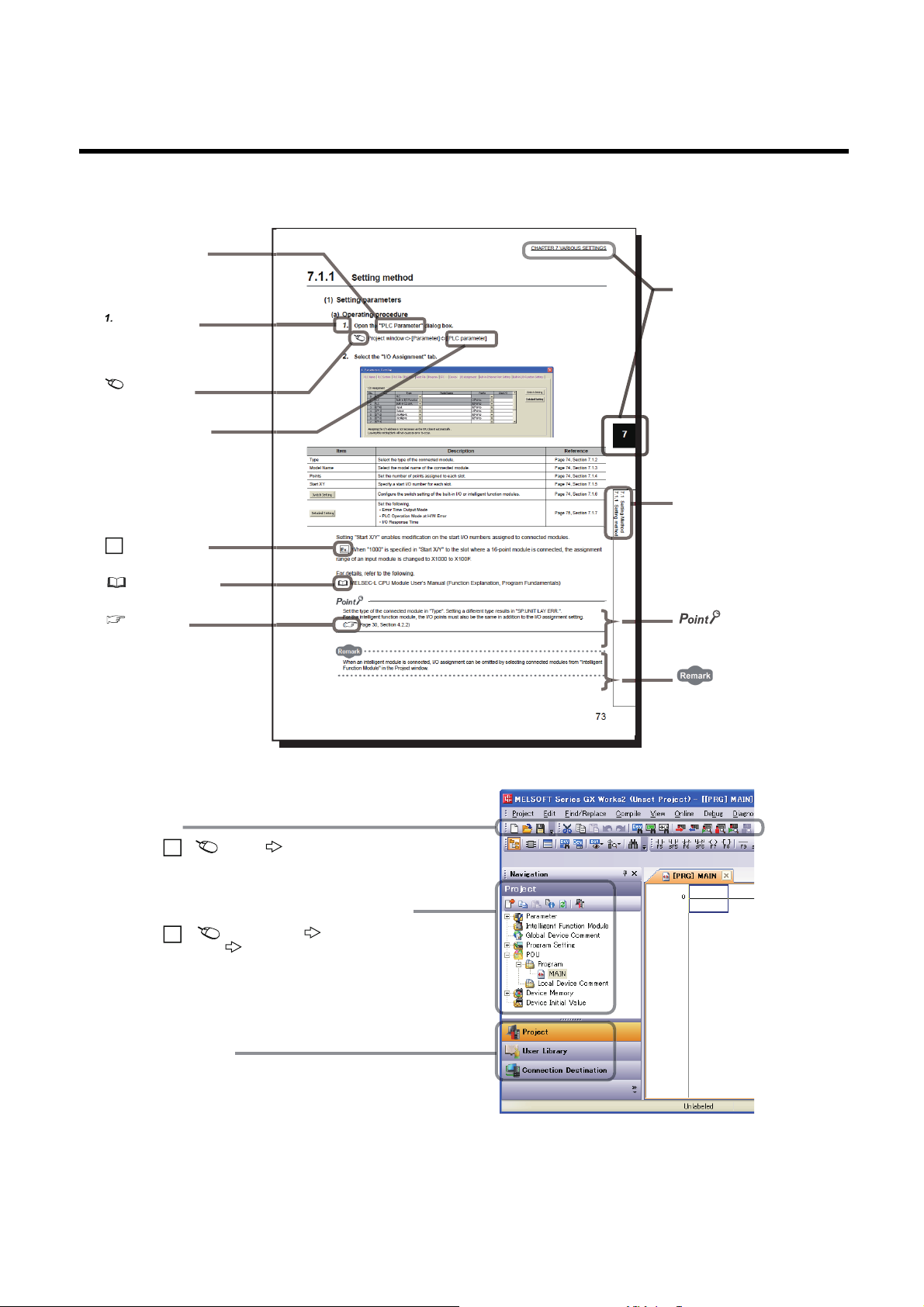
MANUAL PAGE ORGANIZATION
The section of
the current page is shown.
The chapter of
the current page is shown.
"" is used for window
names and items.
[ ] is used for items
in the menu bar and
the project window.
shows operating
procedures.
shows reference
manuals.
shows notes that
require attention.
shows mouse
operations.
*1
shows
reference pages.
shows setting or
operating examples.
Ex.
shows useful
information.
In this manual, pages are organized and the symbols are used as shown below.
The following illustration is for explanation purpose only, and should not be referred to as an actual documentation.
*1 The mouse operation example (for GX Works2) is provided below.
Menu bar
Ex.
A window selected in the view selection area is displayed.
Ex.
View selection area
[Online] [Write to PLC...]
Select [Online] on the menu bar,
and then select [Write to PLC...].
Project window
[PLC Parameter]
Select [Project] from the view selection
area to open the Project window.
In the Project window, expand [Parameter] and
select [PLC Parameter].
[Parameter]
11

TERMS
Unless otherwise specified, this manual uses the following terms.
Ter m Description
Buffer memory
CC-Link IE Field Network A high-speed and large-capacity open field network that is based on Ethernet (1000BASE-T)
Cyclic transmission
D/A converter module A generic term for the main D/A converter module and extension D/A converter module
Data link A generic term for cyclic transmission and transient transmission
Dedicated instruction An instruction that simplifies programming for using functions of intelligent function modules
Disconnection A process of stopping data link if a data link error occurs
Extension A/D converter module
Extension analog module A generic term for the extension A/D converter module and extension D/A converter module
Extension D/A converter module
Extension I/O module A generic term for extension modules where a digital signal can be input or output
Extension input module A generic term for extension modules where digital signals can be input
Extension module
Extension output module A generic term for extension modules where digital signals can be output
GX Works2
GX Works3
I/O module Another name for the CC-Link IE Field Network remote I/O module
Intelligent device station
Link device A device (RX, RY, RWr, or RWw) in a module on CC-Link IE Field Network
Link special register (SW) Word data that indicates the operating status and data link status of a module on CC-Link IE Field Network
Link special relay (SB) Bit data that indicates the operating status and data link status of a module on CC-Link IE Field Network
Local station
Main A/D converter module The abbreviation for the NZ2GF2BN-60AD4 CC-Link IE Field Network main analog-digital converter module
Main analog module A generic term for the main A/D converter module and main D/A converter module
Main D/A converter module The abbreviation for the NZ2GF2BN-60DA4 CC-Link IE Field Network main digital-analog converter module
Main module
Master station
Master/local module The generic term for the CC-Link IE Field Network master/local module
Network module
Relay station
REMFR The abbreviation for ZP.REMFR.
Remote buffer memory Buffer memory in a remote device station
Remote device station
Remote I/O station A station that exchanges I/O signals (b it data) with the master station by cyclic transmission
A memory in an intelligent function module, where data (such as setting values and monitoring values)
exchanged with a CPU module are stored
A function by which data are periodically exchanged among stations on the same network using link devices
(RX, RY, RWw, and RWr)
The abbreviation for the NZ2EX2B-60AD4 CC-Link IE Field Network extension analog-digital converter
module
The abbreviation for the NZ2EX2BN-60DA4 CC-Link IE Field Network extension digital-analog converter
module
A remote module with no CC-Link IE Field Network communication function. This module cannot be used as a
single module. However, connecting the module to the main module will increase the number of I/O points per
station.
The product name of the software package for the MELSOFT programmable controllers
A station that exchanges I/O signals (bit data) and I/O data (word data) with another station by cyclic
transmission. This station responds to a transient transmission request from another station and also issues a
transient transmission request to another station.
A station that performs cyclic transmission and transient transmission with the master station and other local
stations. The station is controlled by programs in the CPU module or other equivalent modules on the station.
A module with the CC-Link IE Field Network communication function, which can be used as a single remote
module. Extension modules can be connected to this module.
A station that controls the entire network. This station can perform cyclic transmission and transient
transmission with all stations. Only one master station can be used in a network.
A generic term for the following modules:
• CC-Link IE Field Network module
• CC-Link IE Controller Network module
• Ethernet interface module
• MELSECNET/H module
• MELSECNET/10 module
A station that includes two or more network modules. Data are passed through this station to stations on other
networks
A station that exchanges I/O signals (bit data) and I/O data (word data) with another station by cyclic
transmission. This station responds to a transient transmission request from another station.
12

Ter m Description
Remote input (RX)
Remote output (RY)
Remote register (RWr)
Remote register (RWw)
REMTO The abbreviation for ZP.REMTO.
Reserved station A station reserved for future use. This station is not actually connected, but counted as a connected station
Return A process of restarting data link when a station recovers from an error
Simple motion module The abbreviation for the QD77GF CC-Link IE Field Network simple motion module
Slave station
Transient transmission
Bit data input from a slave station to the master station (For some areas in a local station, data are input in the
opposite direction.)
User's manual for the master/local module used
Bit data output from the master station to a slave station (For some areas in a local station, data are output in
the opposite direction.)
User's manual for the master/local module used
Word data input from a slave station to the master station (For some areas in a local station, data are input in
the opposite direction.)
User's manual for the master/local module used
Word data output from the master station to a slave station (For some areas in a local station, data are input in
the opposite direction.)
User's manual for the master/local module used
A generic term for stations other than a master station: local station, remote I/O station, remote device station,
and intelligent device station
A function of communication with another station, which is used when requested by a dedicated instruction or
GX Works2
13
PACKING LIST
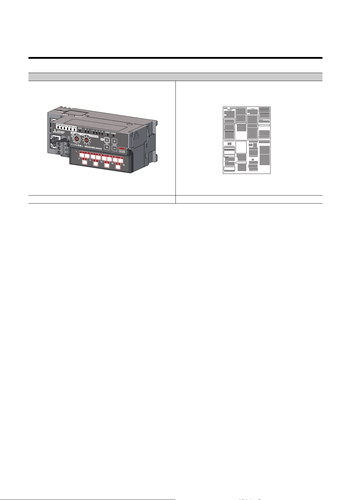
The following items are included in the package of this product. Before use, check that all the items are included.
D/A converter module
Module (The figure above shows the main D/A converter module.) Before Using the Product
14
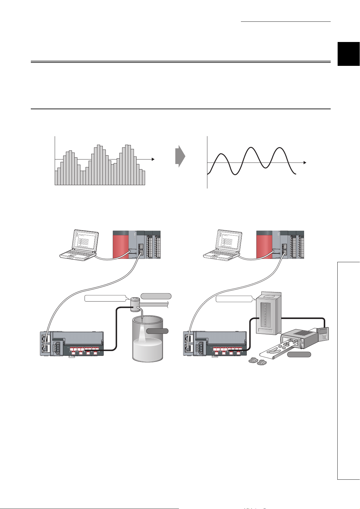
CHAPTER 1 D/A CONVERTER MODULE
Digital signal as a discrete sequence
D/A conversion
Analog signal as a continuous amount
Master station
CC-Link IE Field Network
Main D/A converter module
Control valve
Flow control
Tank
Master station
CC-Link IE Field Network
Main D/A converter module
Power conditioner
Heater
CHAPTER 1 D/A CONVERTER MODULE
This chapter describes the applications and features of the D/A converter module.
1.1 Application
The D/A converter module converts digital data to analog signals and outputs them to the external devices.
The digital data is set up from the master station.
Using the D/A converter module allows the flow and the temperature to be controlled from the master station.
1
1.1 Application
15
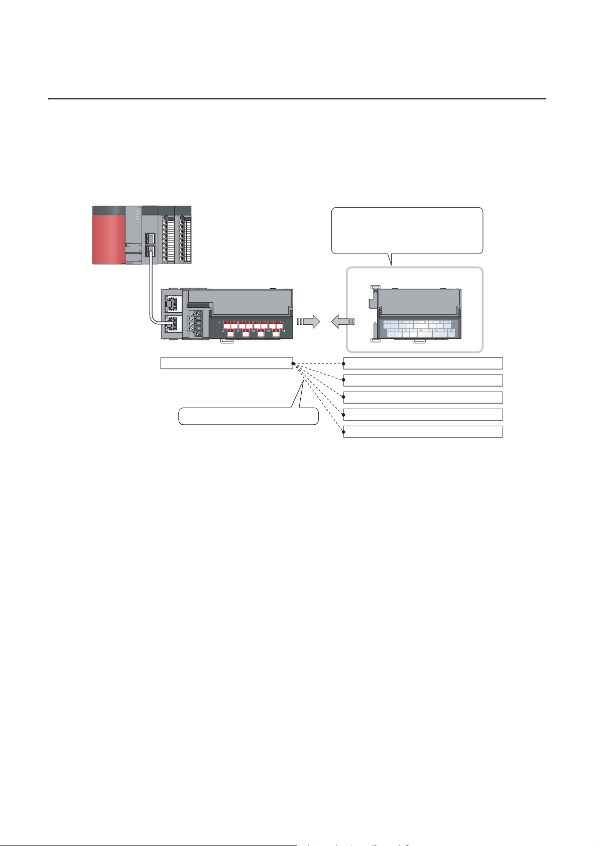
1.2 Features
Flexible combinations are possible.
Extension output module (sink type)
Extension output module (source type)
Extension input module
Various extension modules can be
connected according to the application.
No wiring of wires and Ethernet cables
is required.
Extension moduleMain module
Main D/A converter module
Extension A/D converter module
Extension D/A converter module
(1) Flexible system configuration
The employed connection block type provides the combined use of a main module and an extension module.
A flexible configuration can be achieved because various extension modules can be connected.
In addition, the main module always monitors the connection status of the extension module, leading to an early
detection of connection failure.
(2) Easy setting of station numbers
Station numbers are set with the rotary switch on the front of the module, where setting and checking the station
numbers are easy.
(3) Improved response by high-speed conversion
The high-speed conversion, 100s/channel, has been achieved.
(4) Reliability with high accuracy
The obtained accuracy for the maximum value of analog output value is high: 0.2% at an ambient temperature
of 25 5; and 0.3% at an ambient temperature of 0 to 55.
(5) D/A conversion at any desired timing
D/A conversion is performed on a digital value immediately after the input of a trigger output request for each
channel.
The combination with the external signal assignment function allows direct input of a trigger output request from
the extension input module, which has the following advantages:
• Being free from the effect of the sequence scan and link scan, analog output values can be constantly
obtained at a given timing, which leads to the improvement of the reliability.
• Analog output values can be obtained without any program, which leads to a reduction in the cost of creating
a program.
16
CHAPTER 1 D/A CONVERTER MODULE
(6) Change to any scale
D/A conversion values can be converted to be within any scale, the range of which is determined arbitrarily.
According to a digital value to be input, the scale can be changed without any program, resulting in cost
reduction.
(7) Error detection and error monitoring
An alert issued for a digital value exceeding the range set in advance allows monitoring abnormality of a digital
value and limiting the output of a digital value.
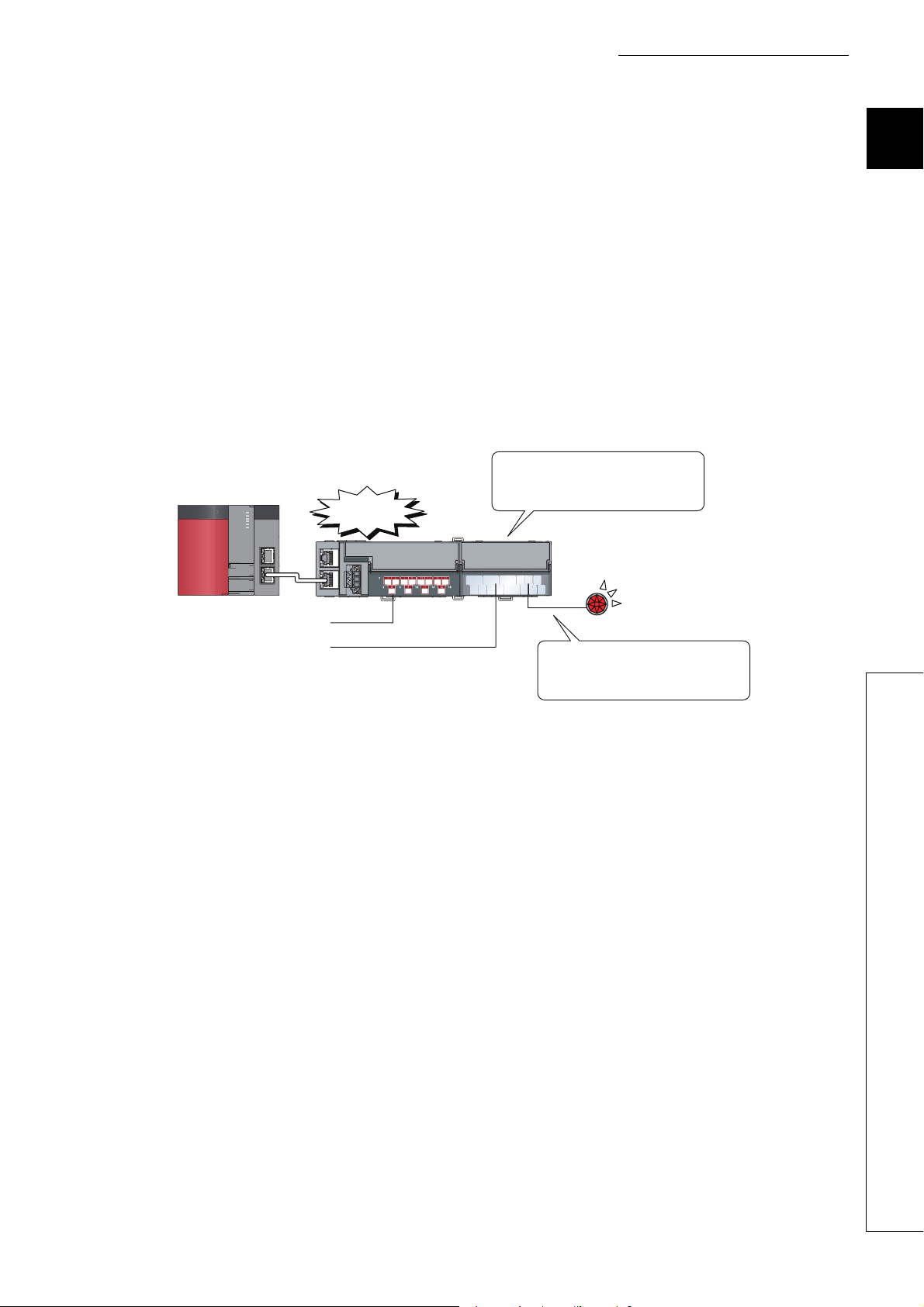
(8) Output without an influence of the sequence scan and link scan
Using the external signal assignment function allows the output of an error status or an alert status from the
extension output module in the event of an error or an alert.
This output is free from the influence of the sequence scan and link scan.
An error signal occurred in the D/A
converter module can be output to
An error has
occurred.
the extension output module directly.
1
Error lamp
Main D/A converter module
Extension output module
Programming is not necessary to
turn on an error lamp when an error
occurs.
(external device)
(9) Support for the CC-Link IE Field Network synchronous communication
function
D/A conversion can be performed with a synchronization period of the master station that supports the CC-Link
IE Field Network synchronous communication function.
This enables the D/A converter module to operate at the same timing of other slave stations sharing the same
network.
1.2 Features
17
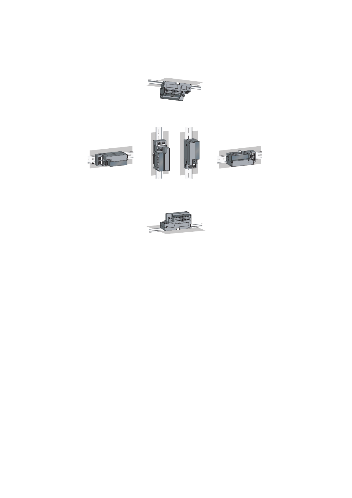
(10)Various installation methods
The module can be installed in six directions using a DIN rail.
Downward installation
DIN rail
Vertical installation Horizontal installation Horizontal installation
Upward installation
(upside down)
(11)Easy module replacement
The terminal block for module power supply and FG, and the terminal block for analog output signals have a two-
piece structure, where the module can be replaced with the wire connected. In addition, the terminal block for
analog output signals has a lift-up structure, where the terminal block lifts only by loosening the terminal block
mounting screw, enabling it to be removed easily.
(12)Check on the error history
The history of the last 15 errors and occurrence time is stored in the main D/A converter module.
Checking the error information of the past helps to identify the cause at the time of a trouble.
(13)Easy settings by CC IE Field configuration of the engineering tool
The CC IE Field configuration of the engineering tool makes it possible to set parameters on its window, thereby
reducing the programs. In addition, the setting status and the operating status of modules can be checked easily.
18
CHAPTER 2 PART NAMES
*1
3)
2)
4) 5) 6)
1) 7) 8)
*1
9)
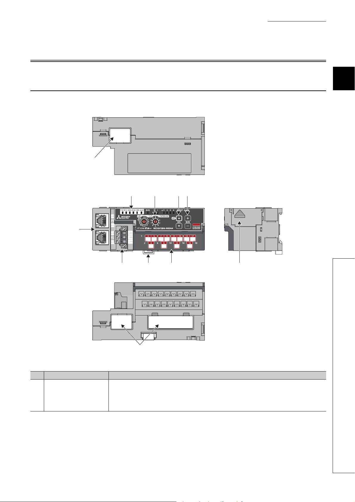
CHAPTER 2 PART NAMES
2.1 Main D/A Converter Module
This section describes part names of the main D/A converter module.
2
2.1 Main D/A Converter Module
*1 Do not remove this seal because it is used for our maintenance purposes.
No. Name Application
1) Station number setting switch
A rotary switch for the following settings and test:
• Station Number Setting ( Page 49, Section 6.1)
• Offset/Gain Setting ( Page 82, Section 7.3)
• Unit Test ( Page 165, Section 11.5)
When operating the station number setting switch, use a flathead screwdriver with a tip width of 3.5mm or less.
19

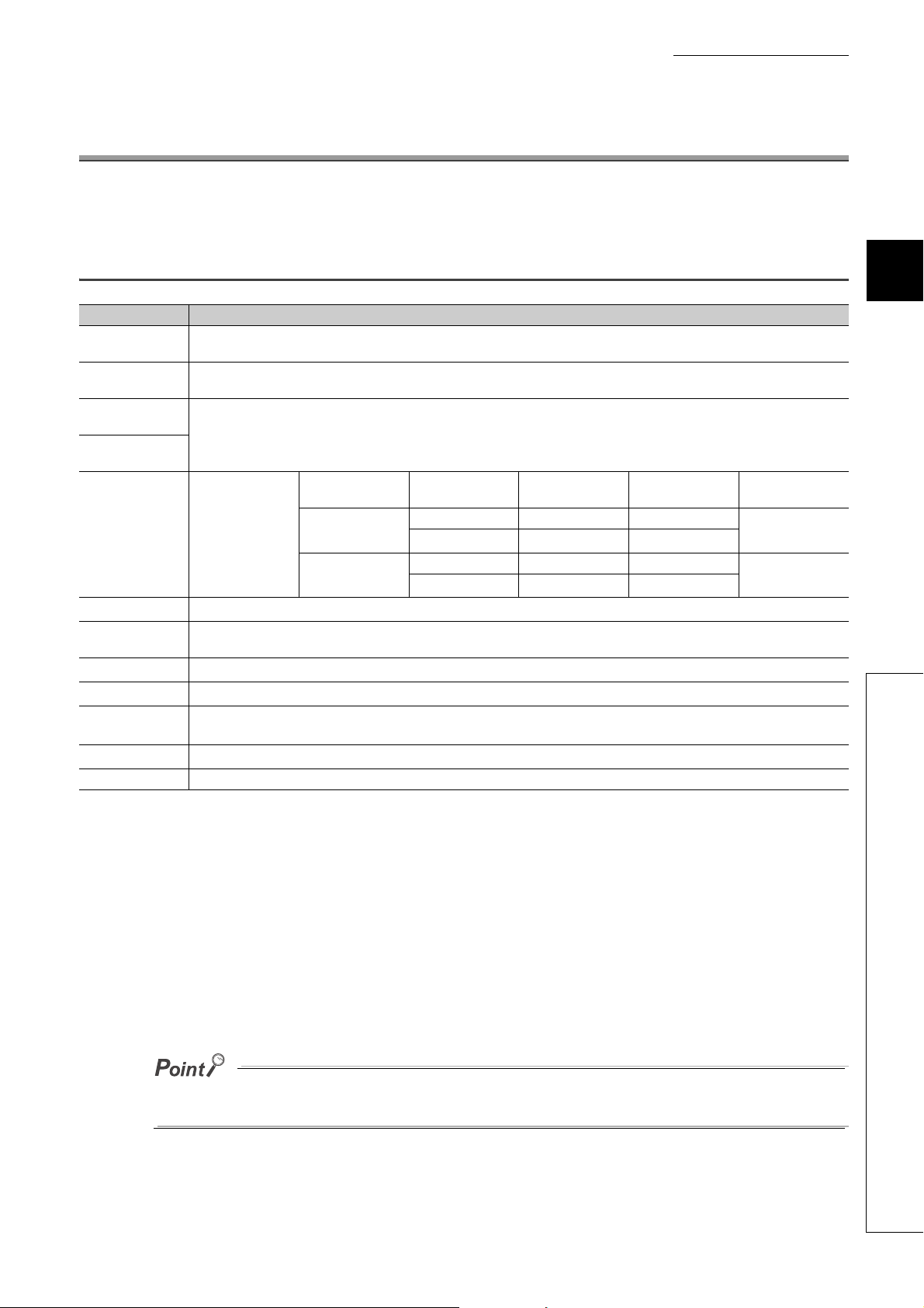
No. Name Application
PW LED (green)
RUN LED (green)
MODE LED (green)
D LINK LED (green)
ERR. LED (red)
2)
ALM LED (red)
O/G LED (green)
V LED (green), I LED (green)
CH1 to CH4 LED (green)
OFFSET LED (green), GAIN
LED (green)
P1
L ER LED (red)
LINK LED (green)
3)
P2
L ER LED (red)
LINK LED (green)
Terminal block for module power
4)
and FG
5) DIN rail hook A hook for mounting a module on a DIN rail
Terminal cover Covers for preventing electric shock while the power is on.
6)
Terminal block for analog output
signals
7) SET/SEL button In offset/gain setting mode, select the set target by pressing button or button.
8) +/- button In offset/gain setting mode, set up the analog output value by pressing + button or - button.
9) Extension connector cover
Indicates the power supply status of the main D/A converter module.
• On: Power-on
• Off: Power-off
Indicates the operating status of the main D/A converter module.
• On: Operating normally; Writing data to the non-volatile memory (while in offset/gain setting mode)
• Off: Major error occurred or in offset/gain setting mode
Indicates the mode of the main D/A converter module.
• On: In online mode
• Flashing: In unit test mode
• Off: In offset/gain setting mode
Indicates the data link status of the main D/A converter module.
• On: Data link in operation (cyclic transmission in progress)
• Flashing: Data link in operation. (cyclic transmission stopped)
• Off: Data link not performed (disconnected)
Indicates the error status of the main D/A converter module.
• On: Moderate error or major error occurred
• Flashing: Warning issued
• Off: Operating normally
Indicates the alert status of the main D/A converter module.
• On: Alert issued
• Flashing: Out-of-range digital value error occurred
• Off: Operating normally
Indicates the module is in offset/gain setting mode.
• On: In offset/gain setting mode
• Off: In a mode other than offset/gain setting mode
Indicates the user range of a set target selected in offset/gain setting mode.
Setting target V LED I LED
User range setting 1 (-10 to 10V) On Off
User range setting 2 (0 to 20mA) Off On
Indicates the channel for the selected setting in the offset/gain setting mode.
• On: The channel corresponding to the number being on is the set target.
• Off: The channel corresponding to the number being off is not the set target.
Indicates whether the selected setting is offset or gain in the offset/gain setting mode.
Set target OFFSET LED GAIN LED
Offset On Off
Gain Off On
PORT1 connector for the connection to CC-Link IE Field Network (RJ45 connector)
Connect an Ethernet cable. ( Page 59, Section 6.5)
There are no restrictions on the connection order of the cables for the P1 connector and P2 connector.
• On: Module received abnormal data, or module performing loopback
• Off: Module received normal data, or module not performing loopback
• On: Link-up
• Off: Link-down
PORT2 connector for the connection to CC-Link IE Field Network (RJ45 connector)
Connect an Ethernet cable. ( Page 59, Section 6.5)
There are no restrictions on the connection order of the cables for the P1 connector and P2 connector.
(same as the LEDs of the P1 connector)
A terminal block for the connection of a module power supply (24VDC) and FG
A two-piece screw terminal block for the connection to an external device
A cover to protect a connector of an extension module. Do not remove the cover if an extension module is not
connected to the connector.
20
CHAPTER 2 PART NAMES
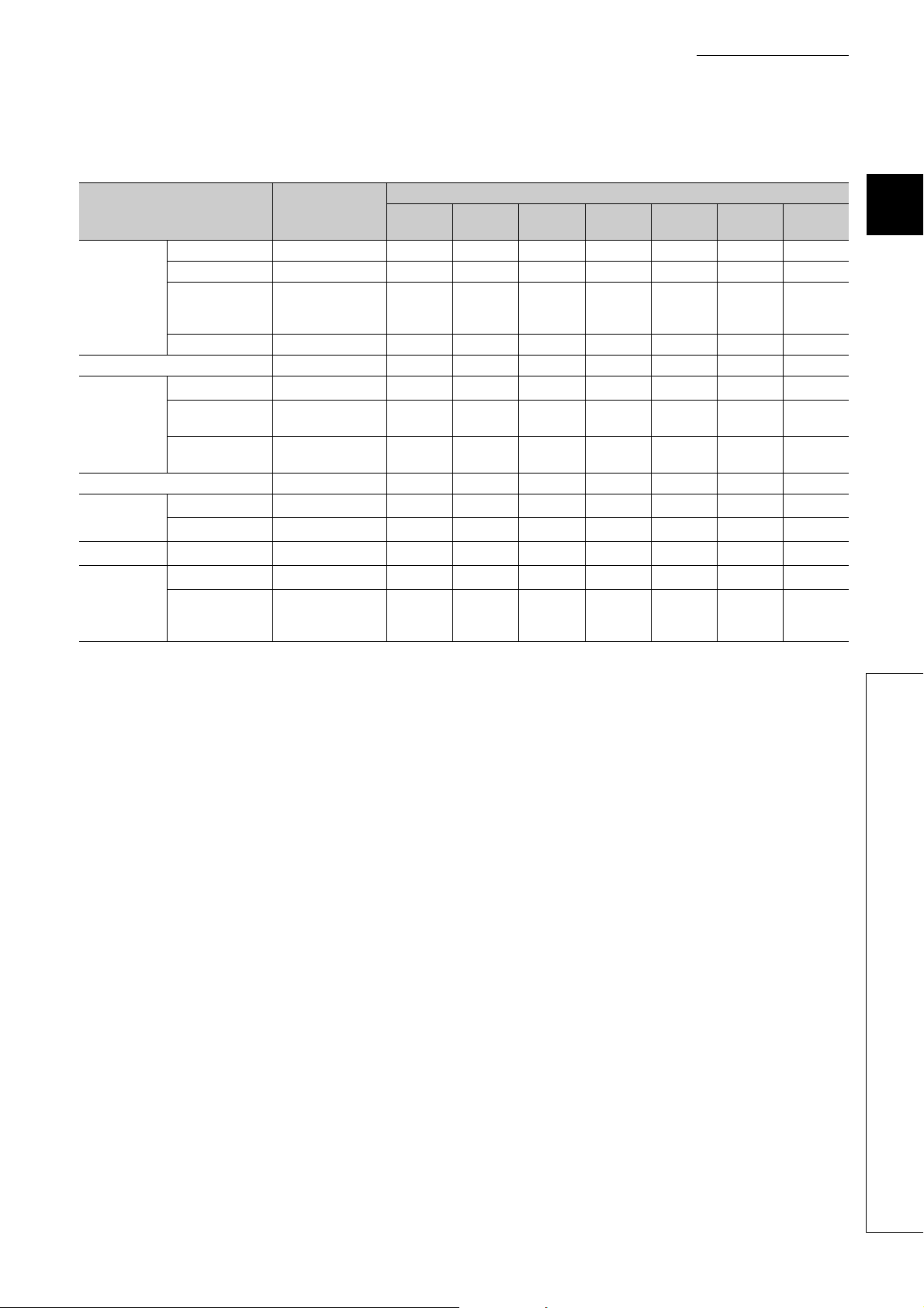
(1) Module status and LED status
The following table shows how module status and LED status correspond each other.
LED status
Module status Data link status
Disconnecting Disconnection On On On Off Off Off Off
Link in progress Data link in operation On On On On Off Off Off
Normal mode
Offset/gain setting mode On Off Off Off Off Off On
Unit test
Communication error Cyclic stop On On On Flashing On Off Off
Error
Warning Minor error On On
Alarm
Reserved station
specification in
progress
Link stop Cyclic stop On On On Flashing Off Off Off
In progress On On Flashing
Completed
successfully
Completed with an
error
Major error On Off
Moderate error On On
Alert issued On On On
Out-of-range digital
value error
occurred
Cyclic stop On On On Flashing Off Off Off
On On Off Off Off Off Off
On On Off Off On Off Off
On On On
PW LED RUN LED
MODE
LED
*2 *1
*2 *1
*2 *1
D LINK
LED
*1
*1 *1
*1 *1
ERR. LED ALM LED O/G LED
Off Off Off
*3 *1
On
On
Flashing
*1
*1
On Off
Flashing Off
Off
Off
Off
2
*1 Either On, Flashing, or Off.
*2 Either On or Off.
*3 A failure of the module may not allow the LED to turn on.
2.1 Main D/A Converter Module
21
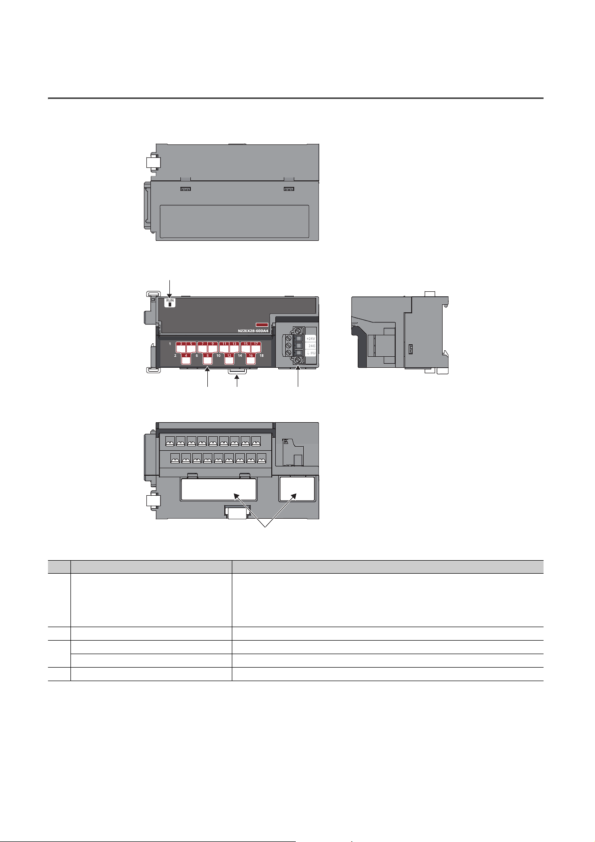
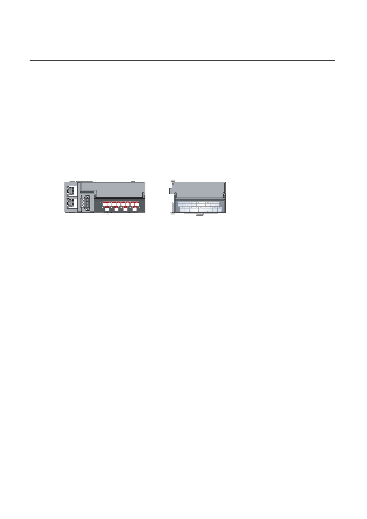
2.2 Extension D/A Converter Module
This section describes part names of the extension D/A converter module.
1)
3) 2) 4)
*1
*1 Do not remove this seal because it is used for our maintenance purposes.
No. Name Application
Indicates the operating status of the extension D/A converter module.
1) RUN LED (green)
2) DIN rail hook A hook for mounting a module on a DIN rail
Terminal cover A cover for preventing electric shock while the power is on
3)
Terminal block for analog output signals A two-piece terminal block for the connection to an external device
4) Terminal block for external power supply and FG A terminal block for the connection of an external power supply (24VDC) and FG
• On: Operating normally.
• Flashing: External power supply being off
• Off: Major error occurred; main analog module being in offset/gain setting mode; or main analog
module being in unit test mode
22
CHAPTER 3 SPECIFICATIONS
This chapter describes the specifications of the D/A converter module.
3.1 General Specifications
Item Specifications
Operating ambient
temperature
Storage ambient
temperature
Operating ambient
humidity
Storage ambient
humidity
Vibration resistance
Shock resistance
Operating
atmosphere
Operating altitude
Installation location
Overvoltage
*3
category
Pollution degree
Equipment class Class
0 to 55
-25 to 75
5 to 95%RH, non-condensing
Compliant with JIS
B 3502 and IEC
61131-2
Compliant with JIS B 3502 and IEC 61131-2 (147m/s
No corrosive gases
*1
0 to 2000m
Inside a control panel
or less
*4
2 or less
Under intermittent
vibration
Under continuous
vibration
*2
Frequency
5 to 8.4Hz 3.5mm
8.4 to 150Hz
5 to 8.4Hz 1.75mm
8.4 to 150Hz
2
, 3 times each in X, Y, and Z directions)
Constant
acceleration
2
9.8m/s
2
4.9m/s
CHAPTER 3 SPECIFICATIONS
Half amplitude Number of sweeps
10 times each in X,
Y, and Z directions
3
3.1 General Specifications
*1 Do not use or store the D/A converter module under pressure higher than the atmospheric pressure at an elevation of 0
meters. Doing so may cause malfunction. When using the D/A converter module under pressure, please consult your
local Mitsubishi representative.
*2 If the environment satisfies the operating ambient temperature, operating ambient humidity and other conditions, the
module can be used even outside the control panel.
*3 This indicates the assumption that the equipment is connected to which type of power distribution system, from the
public electrical power distribution network down to machinery within premises.
Category applies to equipment for which electrical power is supplied from fixed facilities. The surge voltage withstand
level for the equipment with up to the rated voltage of 300V is 2500V.
*4 This index indicates the degree to which conductive material is generated in terms of the environment in which the
equipment is used.
In pollution degree 2, only non-conductive pollution occurs. A temporary conductivity caused by condensation must be
expected occasionally.
For compliance with the EMC Directive, refer to "EMC and Low Voltage Directives" in this manual. ( Page 209, Appendix
7)
23

3.2 Performance Specifications
3.2.1 Main D/A converter module
Item Description
Station type Remote device station
Number of analog output points 4 points (4 channels)/module
Digital input 16-bit signed binary (-16384 to 16383, -288 to 12287, -12288 to 12287)
Analog output
I/O characteristics, maximum
resolution
Conversion
accuracy
Conversion speed
Output short circuit protection Protected
Absolute maximum output Voltage: 15V, Current: 21mA
Isolation method
Withstand voltage
Noise immunity
External interface
Applicable DIN rail TH35-7.5Fe, TH35-7.5Al (compliant with IEC 60715)
Applicable wire
size
*1
*2
Voltage -10 to 10VDC (external load resistance value: 1k to 1M)
Current 0 to 20mADC (external load resistance value: 0 to 600)
Output Output range Digital value Maximum resolution
-10 to 10V -16000 to 16000 0.625mV
Volt ag e
Current
Ambient
temperature
(255)
Ambient
temperature
(0 to 55)
*4
Communication
part
Module power
supply part
I/O part
For power supply Core: 0.5 to 1.5 (20 to 16 AWG)
For I/O Core: 0.3 to 2.0 (22 to 14 AWG)
0.2%
0.3%
100s/channel
Between communication system terminal and all analog output terminals: Photocoupler isolation
Between power supply system terminal and all analog output terminals: Transformer isolation
Between output channels: Non-isolation
Between all power supply and communication system terminals and all analog output terminals
500VAC for 1 minute
Noise voltage 500Vp-p, noise width 1s,
noise frequency 25 to 60Hz (noise simulator condition)
RJ45 connector
Terminal block for module power supply and FG
Tightening torque range for terminal screw (M2.5 screw): 0.5 to 0.6Nm
18-point two-piece terminal block (M3 screw)
Tightening torque range for terminal screw (M3 screw 5.2): 0.43 to 0.57Nm
0 to 5V
1 to 5V 0.333mV
User range setting 1 (-10 to 10V) -12000 to 12000 0.333mV
0 to 20mA
4 to 20mA 1.33A
User range setting 2 (0 to 20mA) 0.95A
0 to 12000
0 to 12000
0.416mV
1.66A
24

Applicable
solderless
terminal
Item Description
TE 0.5-10 (NICHIFU Co., Ltd.) [Applicable wire size: 0.5]
TE 0.75-10 (NICHIFU Co., Ltd.) [Applicable wire size: 0.75]
Terminal block for
module power
supply and FG
Terminal block for
analog output
signals
TE 1.0-10 (NICHIFU Co., Ltd.) [Applicable wire size: 0.9 to 1.0]
TE 1.5-10 (NICHIFU Co., Ltd.) [Applicable wire size: 1.25 to 1.5]
AI 0.5-10WH (Phoenix Contact Co., Ltd.) [Applicable wire size: 0.5]
*3
AI 0.75-10GY (Phoenix Contact Co., Ltd.) [Applicable wire size: 0.75]
AI 1-10RD (Phoenix Contact Co., Ltd.) [Applicable wire size: 1.0]
AI 1.5-10BK (Phoenix Contact Co., Ltd.) [Applicable wire size: 1.5]
RAV1.25-3 (compliant with JIS C 2805) [Applicable wire size: 0.3 to 1.25]
V2-MS3 (JST Mfg. Co., Ltd) [Applicable wire size: 1.25 to 2.0]
RAP2-3SL (Nippon Tanshi Co., Ltd.) [Applicable wire size: 1.25 to 2.0]
TGV2-3N (NICHIFU Co., Ltd.) [Applicable wire size: 1.25 to 2.0]
CHAPTER 3 SPECIFICATIONS
3
Cyclic
transmission
Communication cable
Applicability of extension module Connectable (Max. one module)
External power supply
Weight 0.29kg
RX/RY points 32 points + 16 points Number of extension modules
RWr/RWw points 16 points + Points of each extension module
An Ethernet cable that meets the 1000BASE-T standard:
Category 5e or higher (double shielded, STP), straight cable
24VDC (20.4 to 28.8VDC)
Inrush current: 39.0A, 1ms or lower
Current consumption: 300mA
*1 For details on the I/O conversion characteristics, refer to the following:
• I/O Conversion Characteristics of D/A Conversion ( Page 204, Appendix 4)
*2 Except for the conditions under noise influence.
*3 Do not connect two or more wires to the terminal.
*4 The conversion period varies depending on whether an extension analog module is connected or not. For details, refer
to the following:
• Conversion Speed and Conversion Period ( Page 88, Section 8.5)
3.2 Performance Specifications
25

3.2.2 Extension D/A converter module
Item Description
Number of analog output points 4 points (4 channels)/module
Digital input 16-bit signed binary (-16384 to 16383, -288 to 12287, -12288 to 12287)
Analog output
I/O characteristics, maximum
resolution
Conversion
accuracy
Conversion speed
Output short circuit protection Protected
Absolute maximum output Voltage: 15V, Current: 21mA
Isolation method
Withstand voltage
Noise immunity
External interface
Applicable DIN rail TH35-7.5Fe, TH35-7.5Al (compliant with IEC 60715)
Applicable wire
size
Applicable
solderless
terminal
Cyclic
transmission
Module power
supply
(supplied from the
main module)
External power supply
*1
*2
Voltage -10 to 10VDC (external load resistance value: 1k to 1M)
Current 0 to 20mADC (external load resistance value: 0 to 600)
Output Output range Digital value Maximum resolution
-10 to 10V -16000 to 16000 0.625mV
Volt ag e
Current
Ambient
temperature
(255)
Ambient
temperature
(0 to 55)
*4
External power
supply part
I/O part
For power supply Core: 0.5 to 1.5 (20 to 16 AWG)
For I/O Core: 0.3 to 2.0 (22 to 14 AWG)
Terminal block for
external power
supply and FG
Terminal block for
analog output
signals
RX/RY points 16 points
RWr/RWw points 16 points
Voltage 24VDC (20.4 to 28.8VDC)
Current 95mA
0.2%
0.3%
100s/channel
Between communication system terminal and all analog output terminals: Photocoupler isolation
Between power supply system terminal and all analog output terminals: Transformer insulation
Between output channels: Non-isolation
Between all power supply and communication system terminals and all analog output terminals
500VAC for 1 minute
Noise voltage 500Vp-p, noise width 1s,
noise frequency 25 to 60Hz (noise simulator condition)
Terminal block for external power supply and FG
Tightening torque range for terminal screw (M2.5 screw): 0.5 to 0.6Nm
18-point two-piece terminal block (M3 screw)
Tightening torque range for terminal screw (M3 screw 5.2): 0.43 to 0.57Nm
TE 0.5-10 (NICHIFU Co., Ltd.) [Applicable wire size: 0.5]
TE 0.75-10 (NICHIFU Co., Ltd.) [Applicable wire size: 0.75]
TE 1.0-10 (NICHIFU Co., Ltd.) [Applicable wire size: 0.9 to 1.0]
TE 1.5-10 (NICHIFU Co., Ltd.) [Applicable wire size: 1.25 to 1.5]
AI 0.5-10WH (Phoenix Contact Co., Ltd.) [Applicable wire size: 0.5]
*3
AI 0.75-10GY (Phoenix Contact Co., Ltd.) [Applicable wire size: 0.75]
AI 1-10RD (Phoenix Contact Co., Ltd.) [Applicable wire size: 1.0]
AI 1.5-10BK (Phoenix Contact Co., Ltd.) [Applicable wire size: 1.5]
RAV1.25-3 (compliant with JIS C 2805) [Applicable wire size: 0.3 to 1.25]
V2-MS3 (JST Mfg. Co., Ltd.) [Applicable wire size: 1.25 to 2.0]
RAP2-3SL (Nippon Tanshi Co., Ltd.) [Applicable wire size: 1.25 to 2.0]
TGV2-3N (NICHIFU Co., Ltd.) [Applicable wire size: 1.25 to 2.0]
24VDC (20.4 to 28.8VDC)
Inrush current: 27.5A, 1ms or lower
Current consumption: 135mA
0 to 5V
1 to 5V 0.333mV
0 to 20mA
4 to 20mA 1.33A
0 to 12000
0 to 12000
0.416mV
1.66A
26

Item Description
Weight 0.23kg
*1 For details on the I/O conversion characteristic, refer to the following:
• I/O Conversion Characteristics of D/A Conversion ( Page 204, Appendix 4)
*2 Except for the conditions under noise influence.
*3 Do not connect two or more wires to the terminal.
*4 For the conversion period with the extension D/A converter module connected, refer to the following:
• Conversion Speed and Conversion Period ( Page 88, Section 8.5)
CHAPTER 3 SPECIFICATIONS
3
3.2 Performance Specifications
27
3.3 How to Calculate Current Consumption
Main D/A converter module Extension output module
NZ2GF2BN-60DA4
Module power supply current:
300mA
NZ2EX2B1-16T
Module power supply current:
30mA
330mA
(Total current consumption)
+=
The total current consumption of the modules is calculated by summing the module power supply current in the main
D/A converter module and extension module.
For the value of the module power supply current, refer to the specifications of each module.
• Performance specifications of main D/A converter module ( Page 24, Section 3.2.1)
• Performance specifications of extension D/A converter module ( Page 26, Section 3.2.2)
• Performance Specifications of extension I/O module ( CC-Link IE Field Network Remote I/O Module
User's Manual)
• Performance specifications of extension A/D converter module ( CC-Link IE Field Network Analog-Digital
Converter Module User's Manual)
The value of the module power supply current in the extension module described in the specifications is the value of
the module power supply current supplied from the main D/A converter module.
28
 Loading...