

Mitsubishi Electric NZ2GF12A4-16D, NZ2GF12A4-16DE, NZ2GF12A2-16T, NZ2GF12A2-16TE, NZ2GF12A42-16DT User Manual
...Page 1

CC-Link IE Field Network
Waterproof/Dustproof Remote I/O Module
User's Manual
-NZ2GF12A4-16D
-NZ2GF12A4-16DE
-NZ2GF12A2-16T
-NZ2GF12A2-16TE
-NZ2GF12A42-16DT
-NZ2GF12A42-16DTE
Page 2

Page 3

COPYRIGHT
This document is protected by the law of copyright, whereby all rights established therein remain with the company Mitsubishi
Electric Corporation. Reproduction of this document or parts of this document is only permissible within the limits of the legal
determination of Copyright Law. Alteration or abridgement of the document is not permitted without the explicit written
approval of the company Mitsubishi Electric Corporation.
PRECAUTIONS REGARDING WARRANTY
This product is jointly developed and manufactured with Molex. Thus, warranty information is different from that of other
MELSEC products. Please confirm the following restrictions before purchase.
Gratis Warranty Term
Warranty period is one year after delivery.(Maximum of 18 months after produced)
Repair and Analysis
Please note that repairs and failure analysis are refused due to the structure of this product. Therefore, free replacement is
arranged for the failure of our responsibility during the warranty period.
1
Page 4
SAFETY PRECAUTIONS
WARNING
Indicates that incorrect handling may cause hazardous conditions, resulting in
death or severe injury.
CAUTION
Indicates that incorrect handling may cause hazardous conditions, resulting in
minor or moderate injury or property damage.
(Read these precautions before using this product.)
Before using this product, please read this manual and the relevant manuals carefully and pay full attention to safety to handle
the product correctly.
The precautions given in this manual are concerned with this product only. For the safety precautions of the programmable
controller system, refer to the user's manual for the CPU module used.
In this manual, the safety precautions are classified into two levels: " WARNING" and " CAUTION".
Under some circumstances, failure to observe the precautions given under " CAUTION" may lead to serious
consequences.
Observe the precautions of both levels because they are important for personal and system safety.
Make sure that the end users read this manual and then keep the manual in a safe place for future reference.
[Design Precautions]
WARNING
● When a communication failure occurs in the network, data in the master module are held. Check Data
link status (each station) (SW00B0 to SW00B7) and configure an interlock circuit in the program to
ensure that the entire system will operate safely.
● When the module is disconnected due to a communication failure in the network or the CPU module is
in the STOP status, all outputs are held or turned off according to the parameter setting.
Configure an interlock circuit in the program to ensure that the entire system will always operate
safely even in such a case. If not, an accident may occur due to an incorrect output or malfunction.
● Outputs may remain on or off due to a failure of the module. Configure an external circuit for
monitoring output signals that could cause a serious accident.
● Do not use any "use prohibited" signals as a remote input or output signal. These signals are reserved
for system use. Do not write any data to the "use prohibited" areas in the remote register. If these
operations are performed, an accident may occur due to an incorrect output or malfunction.
[Design Precautions]
CAUTION
● Do not install the control lines or communication cables together with the main circuit lines or power
cables. Keep a distance of 100mm or more between them. Failure to do so may result in malfunction
due to noise.
● During control of an inductive load such as a lamp, heater, or solenoid valve, a large current
(approximately ten times greater than normal) may flow when the output is turned from off to on.
Therefore, use a module that has a sufficient current rating.
2
Page 5

[Installation Precautions]
WARNING
● Shut off the load power supply (all phases) used in the system before mounting or removing a
module. Failure to do so may result in electric shock or cause the module to fail or malfunction.
[Installation Precautions]
CAUTION
● Use the module in an environment that meets the general specifications in this manual. Failure to do
so may result in electric shock, fire, malfunction, or damage to or deterioration of the product.
● Do not directly touch any conductive parts and electronic components of the module. Doing so can
cause malfunction or failure of the module.
● Securely fix the module with mounting screws. Failure to do so may cause the module to fail due to
increasing effects of vibrations.
● Securely connect the cable connectors. Poor contact may cause malfunction.
● After the first use of the product, do not connect/remove the connector more than 50 times (IEC
61131-2 compliant). Exceeding the limit may cause malfunction.
3
Page 6

[Wiring Precautions]
WARNING
● Shut off the load power supply (all phases) used in the system before wiring. Failure to do so may
result in electric shock or cause the module to fail or malfunction.
[Wiring Precautions]
CAUTION
● Individually ground the FG metal fitting of the programmable controller with a ground resistance of 100
ohms or less. Failure to do so may result in electric shock or malfunction.
● Check the rated voltage and terminal layout before wiring to the module, and connect the cables
correctly. Connecting a power supply with a different voltage rating or incorrect wiring may cause a fire
or failure.
● Tighten the waterproof caps within the specified torque range. Undertightening can cause short
circuit, fire, or malfunction. Overtightening can damage the waterproof cap, resulting in short circuit or
malfunction.
● The module meets IP67 only when all of the waterproof plugs and waterproof caps are attached and
the cover of the station number setting switch is securely fixed with a screw.
● Do not connect a communication cable to an I/O connector instead of to a communication connector.
Both connectors are the same in form. Connecting the cable to a wrong connector may cause the
module to fail or malfunction.
● Prevent foreign matter such as dust or wire chips from entering the module. Such foreign matter can
cause a fire, failure, or malfunction.
● Place the cables in a duct or clamp them. If not, dangling cable may swing or inadvertently be pulled,
resulting in damage to the module or cables or malfunction due to poor contact.
● Do not install the control lines or communication cables together with the main circuit lines or power
cables. Keep a distance of 100mm or more between them. Failure to do so may result in malfunction
due to noise.
● When disconnecting the cable from the module, do not pull the cable by the cable part. For the cable
with connector, hold the connector part of the cable. Pulling the cable connected to the module may
result in malfunction or damage to the module or cable.
● When an overcurrent caused by an error of an external device or a failure of the programmable
controller flows for a long time, it may cause smoke and fire. To prevent this, configure an external
safety circuit, such as a fuse.
● Wiring and replacement of a module must be performed by qualified maintenance personnel with
knowledge of protection against electric shock. For wiring methods, refer to "INSTALLATION AND
WIRING" in this manual.
4
Page 7
[Startup and Maintenance Precautions]
WARNING
● Do not touch any connector while power is on. Doing so will cause electric shock or malfunction.
● Shut off the load power supply (all phases) used in the system before cleaning the module or
retightening screws or connector screws. Failure to do so may cause the module to fail or malfunction.
[Startup and Maintenance Precautions]
CAUTION
● Do not disassemble or modify the module. Doing so may cause failure, malfunction, injury, or a fire.
● Do not drop or apply strong shock to the module. Doing so may damage the module.
● Shut off the load power supply (all phases) used in the system before mounting or removing a
module. Failure to do so may cause the module to fail or malfunction.
● After the first use of the product, do not connect/remove the connectors more than 50 times (IEC
61131-2 compliant). Exceeding the limit may cause malfunction.
● Before handling the module or connection cables, touch a conducting object such as a grounded
metal to discharge the static electricity from the human body. Failure to do so may cause the module
to fail or malfunction.
● Startup and maintenance of a control panel must be performed by qualified maintenance personnel
with knowledge of protection against electric shock. Lock the control panel so that only qualified
maintenance personnel can operate it.
[Disposal Precautions]
CAUTION
● When disposing of this product, treat it as industrial waste.
5
Page 8

CONDITIONS OF USE FOR THE PRODUCT
(1) Mitsubishi programmable controller ("the PRODUCT") shall be used in conditions;
i) where any problem, fault or failure occurring in the PRODUCT, if any, shall not lead to any major or serious accident;
and
ii) where the backup and fail-safe function are systematically or automatically provided outside of the PRODUCT for the
case of any problem, fault or failure occurring in the PRODUCT.
(2) The PRODUCT has been designed and manufactured for the purpose of being used in general industries.
MITSUBISHI SHALL HAVE NO RESPONSIBILITY OR LIABILITY (INCLUDING, BUT NOT LIMITED TO ANY AND ALL
RESPONSIBILITY OR LIABILITY BASED ON CONTRACT, WARRANTY, TORT, PRODUCT LIABILITY) FOR ANY
INJURY OR DEATH TO PERSONS OR LOSS OR DAMAGE TO PROPERTY CAUSED BY the PRODUCT THAT ARE
OPERATED OR USED IN APPLICATION NOT INTENDED OR EXCLUDED BY INSTRUCTIONS, PRECAUTIONS, OR
WARNING CONTAINED IN MITSUBISHI'S USER, INSTRUCTION AND/OR SAFETY MANUALS, TECHNICAL
BULLETINS AND GUIDELINES FOR the PRODUCT.
("Prohibited Application")
Prohibited Applications include, but not limited to, the use of the PRODUCT in;
• Nuclear Power Plants and any other power plants operated by Power companies, and/or any other cases in which the
public could be affected if any problem or fault occurs in the PRODUCT.
• Railway companies or Public service purposes, and/or any other cases in which establishment of a special quality
assurance system is required by the Purchaser or End User.
• Aircraft or Aerospace, Medical applications, Train equipment, transport equipment such as Elevator and Escalator,
Incineration and Fuel devices, Vehicles, Manned transportation, Equipment for Recreation and Amusement, and
Safety devices, handling of Nuclear or Hazardous Materials or Chemicals, Mining and Drilling, and/or other
applications where there is a significant risk of injury to the public or property.
Notwithstanding the above, restrictions Mitsubishi may in its sole discretion, authorize use of the PRODUCT in one or
more of the Prohibited Applications, provided that the usage of the PRODUCT is limited only for the specific
applications agreed to by Mitsubishi and provided further that no special quality assurance or fail-safe, redundant or
other safety features which exceed the general specifications of the PRODUCTs are required. For details, please
contact the Mitsubishi representative in your region.
6
Page 9

INTRODUCTION
Thank you for purchasing the CC-Link IE Field Network waterproof/dustproof remote I/O module (hereafter abbreviated as I/O
module).
This manual describes the procedures, system configuration, parameter settings, functions, and troubleshooting of the I/O
module.
Before using this product, please read this manual and the relevant manuals carefully and develop familiarity with the
functions and performance of the I/O module to handle the product correctly.
When applying the program examples introduced in this manual to an actual system, ensure the applicability and confirm that
it will not cause system control problems.
Relevant products
NZ2GF12A4-16D, NZ2GF12A4-16DE, NZ2GF12A2-16T, NZ2GF12A2-16TE, NZ2GF12A42-16DT, NZ2GF12A42-16DTE
Unless otherwise specified, this manual describes the program examples in which the remote I/O signals and
remote registers are assigned for an I/O combined module as follows.
• Remote input signal: RX0 to RX7
• Remote output signal: RY8 to RYF
• Remote register: RWr0 to RWrB, RWw0 to RWwB
For the assignment of remote I/O signals and remote registers, refer to the following.
User's manual for the master/local module used
7
Page 10

RELEVANT MANUALS
CC-Link IE Field Network (relevant) manuals
When using the CC-Link IE Field Network for the first time, refer to the CC-Link IE Field Network Master/Local Module User's
Manual or Simple Motion Module User's Manual first. The following shows the structure of the CC-Link IE Field Network
manuals.
Manual name
<manual number>
MELSEC-Q CC-Link IE Field Network Master/Local Module User's Manual
<SH-080917ENG>
MELSEC-L CC-Link IE Field Network Master/Local Module User's Manual
<SH-080972ENG>
MELSEC iQ-R Ethernet/CC-Link IE User's Manual (Startup)
<SH-081256ENG>
MELSEC iQ-R CC-Link IE Field Network User's Manual (Application)
<SH-081259ENG>
MELSEC iQ-R Inter-Module Synchronization Function Reference Manual
<SH-081401ENG>
MELSEC-Q QD77GF Simple Motion Module User's Manual (Network)
<IB-0300203>
MELSEC-Q QD77GF Simple Motion Module User's Manual (Positioning Control)
<IB-0300202>
Description
Overview of the CC-Link IE Field Network, and specifications,
procedures before operation, system configuration, installation, wiring,
settings, functions, programming, and troubleshooting of the QJ71GF11T2
Overview of the CC-Link IE Field Network, and specifications,
procedures before operation, system configuration, installation, wiring,
settings, functions, programming, and troubleshooting of the LJ71GF11T2
Specifications, procedures before operation, system configuration,
wiring, and communication examples of Ethernet, CC-Link IE Controller
Network, and CC-Link IE Field Network
Functions, parameter settings, programming, troubleshooting, I/O
signals, and buffer memory of CC-Link IE Field Network
Inter-module synchronization function, which controls multiple modules
synchronously
Functions, programming, and troubleshooting for CC-Link IE Field
Network of the QD77GF16
Specifications of the QD77GF16 and information on how to establish a
system, maintenance and inspection, and troubleshooting.
Functions, programming and buffer memory for the positioning control of
the QD77GF16
8
Page 11

CONTENTS
COPYRIGHT . . . . . . . . . . . . . . . . . . . . . . . . . . . . . . . . . . . . . . . . . . . . . . . . . . . . . . . . . . . . . . . . . . . . . . . . . . . . . .1
PRECAUTIONS REGARDING WARRANTY . . . . . . . . . . . . . . . . . . . . . . . . . . . . . . . . . . . . . . . . . . . . . . . . . . . . .1
SAFETY PRECAUTIONS . . . . . . . . . . . . . . . . . . . . . . . . . . . . . . . . . . . . . . . . . . . . . . . . . . . . . . . . . . . . . . . . . . . .2
CONDITIONS OF USE FOR THE PRODUCT . . . . . . . . . . . . . . . . . . . . . . . . . . . . . . . . . . . . . . . . . . . . . . . . . . . .6
INTRODUCTION. . . . . . . . . . . . . . . . . . . . . . . . . . . . . . . . . . . . . . . . . . . . . . . . . . . . . . . . . . . . . . . . . . . . . . . . . . .7
RELEVANT MANUALS . . . . . . . . . . . . . . . . . . . . . . . . . . . . . . . . . . . . . . . . . . . . . . . . . . . . . . . . . . . . . . . . . . . . . .8
TERMS . . . . . . . . . . . . . . . . . . . . . . . . . . . . . . . . . . . . . . . . . . . . . . . . . . . . . . . . . . . . . . . . . . . . . . . . . . . . . . . . .12
CHAPTER 1 PRODUCT LINEUP 13
1.1 I/O Module . . . . . . . . . . . . . . . . . . . . . . . . . . . . . . . . . . . . . . . . . . . . . . . . . . . . . . . . . . . . . . . . . . . . . . . . . . . . . 13
1.2 Recommended Connector List . . . . . . . . . . . . . . . . . . . . . . . . . . . . . . . . . . . . . . . . . . . . . . . . . . . . . . . . . . . . 14
CHAPTER 2 PART NAMES 16
CHAPTER 3 SPECIFICATIONS 19
3.1 General Specifications . . . . . . . . . . . . . . . . . . . . . . . . . . . . . . . . . . . . . . . . . . . . . . . . . . . . . . . . . . . . . . . . . . .19
3.2 I/O Module Specifications. . . . . . . . . . . . . . . . . . . . . . . . . . . . . . . . . . . . . . . . . . . . . . . . . . . . . . . . . . . . . . . . .20
Input module . . . . . . . . . . . . . . . . . . . . . . . . . . . . . . . . . . . . . . . . . . . . . . . . . . . . . . . . . . . . . . . . . . . . . . . . . . . .20
Output module. . . . . . . . . . . . . . . . . . . . . . . . . . . . . . . . . . . . . . . . . . . . . . . . . . . . . . . . . . . . . . . . . . . . . . . . . . . 26
I/O combined module . . . . . . . . . . . . . . . . . . . . . . . . . . . . . . . . . . . . . . . . . . . . . . . . . . . . . . . . . . . . . . . . . . . . .34
3.3 Function List . . . . . . . . . . . . . . . . . . . . . . . . . . . . . . . . . . . . . . . . . . . . . . . . . . . . . . . . . . . . . . . . . . . . . . . . . . .44
3.4 List of Remote I/O Signals . . . . . . . . . . . . . . . . . . . . . . . . . . . . . . . . . . . . . . . . . . . . . . . . . . . . . . . . . . . . . . . . 46
3.5 List of Remote Register . . . . . . . . . . . . . . . . . . . . . . . . . . . . . . . . . . . . . . . . . . . . . . . . . . . . . . . . . . . . . . . . . .48
3.6 List of Remote Buffer Memory . . . . . . . . . . . . . . . . . . . . . . . . . . . . . . . . . . . . . . . . . . . . . . . . . . . . . . . . . . . . . 50
CHAPTER 4 PROCEDURES BEFORE OPERATION 60
CHAPTER 5 SYSTEM CONFIGURATION 62
5.1 Applicable Systems. . . . . . . . . . . . . . . . . . . . . . . . . . . . . . . . . . . . . . . . . . . . . . . . . . . . . . . . . . . . . . . . . . . . . . 62
CHAPTER 6 INSTALLATION AND WIRING 64
6.1 Setting Switch . . . . . . . . . . . . . . . . . . . . . . . . . . . . . . . . . . . . . . . . . . . . . . . . . . . . . . . . . . . . . . . . . . . . . . . . . . 64
Station number setting with the station number setting switch . . . . . . . . . . . . . . . . . . . . . . . . . . . . . . . . . . . . . . 64
6.2 Installation Environment and Installation Position . . . . . . . . . . . . . . . . . . . . . . . . . . . . . . . . . . . . . . . . . . . . 66
Installation environment. . . . . . . . . . . . . . . . . . . . . . . . . . . . . . . . . . . . . . . . . . . . . . . . . . . . . . . . . . . . . . . . . . . . 66
Installation position . . . . . . . . . . . . . . . . . . . . . . . . . . . . . . . . . . . . . . . . . . . . . . . . . . . . . . . . . . . . . . . . . . . . . . . 67
Installation direction. . . . . . . . . . . . . . . . . . . . . . . . . . . . . . . . . . . . . . . . . . . . . . . . . . . . . . . . . . . . . . . . . . . . . . .67
6.3 Installation . . . . . . . . . . . . . . . . . . . . . . . . . . . . . . . . . . . . . . . . . . . . . . . . . . . . . . . . . . . . . . . . . . . . . . . . . . . . . 68
Fixing the I/O module . . . . . . . . . . . . . . . . . . . . . . . . . . . . . . . . . . . . . . . . . . . . . . . . . . . . . . . . . . . . . . . . . . . . .68
6.4 Wiring the Power Supply . . . . . . . . . . . . . . . . . . . . . . . . . . . . . . . . . . . . . . . . . . . . . . . . . . . . . . . . . . . . . . . . . 68
6.5 Wiring of Ethernet Cable. . . . . . . . . . . . . . . . . . . . . . . . . . . . . . . . . . . . . . . . . . . . . . . . . . . . . . . . . . . . . . . . . . 69
6.6 Attaching Waterproof Caps . . . . . . . . . . . . . . . . . . . . . . . . . . . . . . . . . . . . . . . . . . . . . . . . . . . . . . . . . . . . . . .71
CONTENTS
CHAPTER 7 VARIOUS SETTINGS 72
7.1 Parameter Setting . . . . . . . . . . . . . . . . . . . . . . . . . . . . . . . . . . . . . . . . . . . . . . . . . . . . . . . . . . . . . . . . . . . . . . . 72
7.2 Changing the Parameter . . . . . . . . . . . . . . . . . . . . . . . . . . . . . . . . . . . . . . . . . . . . . . . . . . . . . . . . . . . . . . . . . .77
Changing the network configuration . . . . . . . . . . . . . . . . . . . . . . . . . . . . . . . . . . . . . . . . . . . . . . . . . . . . . . . . . . 77
Changing the parameter without changing the network configuration. . . . . . . . . . . . . . . . . . . . . . . . . . . . . . . . .79
9
Page 12

CHAPTER 8 FUNCTIONS 81
8.1 Error Notification Function. . . . . . . . . . . . . . . . . . . . . . . . . . . . . . . . . . . . . . . . . . . . . . . . . . . . . . . . . . . . . . . . 81
8.2 Input OFF Delay Function. . . . . . . . . . . . . . . . . . . . . . . . . . . . . . . . . . . . . . . . . . . . . . . . . . . . . . . . . . . . . . . . . 84
8.3 Input Response Time Setting Function. . . . . . . . . . . . . . . . . . . . . . . . . . . . . . . . . . . . . . . . . . . . . . . . . . . . . . 86
8.4 Output HOLD/CLEAR Setting Function. . . . . . . . . . . . . . . . . . . . . . . . . . . . . . . . . . . . . . . . . . . . . . . . . . . . . . 87
8.5 Cyclic Data Update Watch Function . . . . . . . . . . . . . . . . . . . . . . . . . . . . . . . . . . . . . . . . . . . . . . . . . . . . . . . . 88
8.6 Number of ON Times Integration Function. . . . . . . . . . . . . . . . . . . . . . . . . . . . . . . . . . . . . . . . . . . . . . . . . . .89
8.7 Output ON/OFF Information Hold Function . . . . . . . . . . . . . . . . . . . . . . . . . . . . . . . . . . . . . . . . . . . . . . . . . .91
8.8 Power Supply Monitoring Function . . . . . . . . . . . . . . . . . . . . . . . . . . . . . . . . . . . . . . . . . . . . . . . . . . . . . . . . . 92
8.9 Short-Circuit Detection Function . . . . . . . . . . . . . . . . . . . . . . . . . . . . . . . . . . . . . . . . . . . . . . . . . . . . . . . . . . . 93
8.10 Fast Logic Function . . . . . . . . . . . . . . . . . . . . . . . . . . . . . . . . . . . . . . . . . . . . . . . . . . . . . . . . . . . . . . . . . . . . .95
8.11 Initial Operation Setting Function . . . . . . . . . . . . . . . . . . . . . . . . . . . . . . . . . . . . . . . . . . . . . . . . . . . . . . . . . . 98
8.12 Protection Function. . . . . . . . . . . . . . . . . . . . . . . . . . . . . . . . . . . . . . . . . . . . . . . . . . . . . . . . . . . . . . . . . . . . . 100
8.13 CC-Link IE Field Network Diagnostic Function . . . . . . . . . . . . . . . . . . . . . . . . . . . . . . . . . . . . . . . . . . . . . . 100
CHAPTER 9 PROGRAMMING 103
9.1 Precautions for Programming . . . . . . . . . . . . . . . . . . . . . . . . . . . . . . . . . . . . . . . . . . . . . . . . . . . . . . . . . . . . 103
9.2 Procedure for Programming. . . . . . . . . . . . . . . . . . . . . . . . . . . . . . . . . . . . . . . . . . . . . . . . . . . . . . . . . . . . . .104
9.3 Program Example . . . . . . . . . . . . . . . . . . . . . . . . . . . . . . . . . . . . . . . . . . . . . . . . . . . . . . . . . . . . . . . . . . . . . . 104
9.4 Program Example for the Number of ON Times Integration Function . . . . . . . . . . . . . . . . . . . . . . . . . . . . 111
Program example for checking the number of ON times. . . . . . . . . . . . . . . . . . . . . . . . . . . . . . . . . . . . . . . . . . 111
Program example for clearing the number of ON times . . . . . . . . . . . . . . . . . . . . . . . . . . . . . . . . . . . . . . . . . . 111
9.5 Program Example for the Fast Logic Function. . . . . . . . . . . . . . . . . . . . . . . . . . . . . . . . . . . . . . . . . . . . . . . 114
Program example for the fast logic function . . . . . . . . . . . . . . . . . . . . . . . . . . . . . . . . . . . . . . . . . . . . . . . . . . . 114
Program example for checking the fast logic enable or disable status . . . . . . . . . . . . . . . . . . . . . . . . . . . . . . . 117
CHAPTER 10 MAINTENANCE AND INSPECTION 119
CHAPTER 11 TROUBLESHOOTING 121
11.1 Checking for the Error Codes and the Warning Codes . . . . . . . . . . . . . . . . . . . . . . . . . . . . . . . . . . . . . . . . 121
11.2 Error Code List . . . . . . . . . . . . . . . . . . . . . . . . . . . . . . . . . . . . . . . . . . . . . . . . . . . . . . . . . . . . . . . . . . . . . . . .124
11.3 Checking the LEDs . . . . . . . . . . . . . . . . . . . . . . . . . . . . . . . . . . . . . . . . . . . . . . . . . . . . . . . . . . . . . . . . . . . . . 128
11.4 Unit Test . . . . . . . . . . . . . . . . . . . . . . . . . . . . . . . . . . . . . . . . . . . . . . . . . . . . . . . . . . . . . . . . . . . . . . . . . . . . . .131
11.5 Troubleshooting for Each Phenomenon . . . . . . . . . . . . . . . . . . . . . . . . . . . . . . . . . . . . . . . . . . . . . . . . . . . .132
11.6 Examples of Troubles with the I/O Module . . . . . . . . . . . . . . . . . . . . . . . . . . . . . . . . . . . . . . . . . . . . . . . . . . 134
Troubleshooting for input circuit . . . . . . . . . . . . . . . . . . . . . . . . . . . . . . . . . . . . . . . . . . . . . . . . . . . . . . . . . . . . 134
Troubleshooting for output circuit . . . . . . . . . . . . . . . . . . . . . . . . . . . . . . . . . . . . . . . . . . . . . . . . . . . . . . . . . . .137
APPENDICES 143
Appendix 1 Details of Remote I/O Signals. . . . . . . . . . . . . . . . . . . . . . . . . . . . . . . . . . . . . . . . . . . . . . . . . . . . . . . . 143
Remote input signal. . . . . . . . . . . . . . . . . . . . . . . . . . . . . . . . . . . . . . . . . . . . . . . . . . . . . . . . . . . . . . . . . . . . . . 143
Remote output signal. . . . . . . . . . . . . . . . . . . . . . . . . . . . . . . . . . . . . . . . . . . . . . . . . . . . . . . . . . . . . . . . . . . . .143
Appendix 2 Details of Remote Registers . . . . . . . . . . . . . . . . . . . . . . . . . . . . . . . . . . . . . . . . . . . . . . . . . . . . . . . . .144
Appendix 3 Details of Remote Buffer Memory Addresses . . . . . . . . . . . . . . . . . . . . . . . . . . . . . . . . . . . . . . . . . . . 154
Appendix 4 EMC and Low Voltage Directives . . . . . . . . . . . . . . . . . . . . . . . . . . . . . . . . . . . . . . . . . . . . . . . . . . . . . 166
Measures to comply with the EMC Directive . . . . . . . . . . . . . . . . . . . . . . . . . . . . . . . . . . . . . . . . . . . . . . . . . . .166
Requirements to compliance with the Low Voltage Directive . . . . . . . . . . . . . . . . . . . . . . . . . . . . . . . . . . . . . . 168
Appendix 5 How to Check Serial Number and Function Version . . . . . . . . . . . . . . . . . . . . . . . . . . . . . . . . . . . . . 169
Appendix 6 External Dimensions . . . . . . . . . . . . . . . . . . . . . . . . . . . . . . . . . . . . . . . . . . . . . . . . . . . . . . . . . . . . . . . 170
10
Page 13

INDEX 172
REVISIONS. . . . . . . . . . . . . . . . . . . . . . . . . . . . . . . . . . . . . . . . . . . . . . . . . . . . . . . . . . . . . . . . . . . . . . . . . . . . .174
WARRANTY . . . . . . . . . . . . . . . . . . . . . . . . . . . . . . . . . . . . . . . . . . . . . . . . . . . . . . . . . . . . . . . . . . . . . . . . . . . .175
TRADEMARKS . . . . . . . . . . . . . . . . . . . . . . . . . . . . . . . . . . . . . . . . . . . . . . . . . . . . . . . . . . . . . . . . . . . . . . . . . .176
CONTENTS
11
Page 14

TERMS
Unless otherwise specified, this manual uses the following terms.
Term Description
Buffer memory A memory in an intelligent function module, where data (such as setting values and monitoring values) exchanged with a
CPU module are stored
CC-Link IE Field Network A high-speed and large-capacity open field network that is based on Ethernet (1000BASE-T)
Cyclic transmission A function by which data are periodically exchanged among stations on the same network using link devices (RX, RY,
Data link A generic term for cyclic transmission and transient transmission
Dedicated instruction An instruction that simplifies programming for using functions of intelligent function modules
Disconnection A process of stopping data link if a data link error occurs
Engineering tool A generic term for GX Works2 and GX Works3
GX Works2 The product name of the software package for the MELSEC programmable controllers
GX Works3
I/O combined module A generic term for modules where a digital signal can be input and output
I/O module The abbreviation for the CC-Link IE Field Network remote I/O module
Input module A generic term for modules where a digital signal can be input
Intelligent device station A station that exchanges I/O signals (bit data) and I/O data (word data) with another station by cyclic transmission. This
Link device A device (RX, RY, RWr, or RWw) in a module on CC-Link IE Field Network
Link special register (SW) Word data that indicates the operating status and data link status of a module on CC-Link IE Field Network
Link special relay (SB) Bit data that indicates the operating status and data link status of a module on CC-Link IE Field Network
Local station A station that performs cyclic transmission and transient transmission with the master station and other local stations.
Master station A station that controls the entire network. This station can perform cyclic transmission and transient transmission with all
Master/local module The abbreviation for the CC-Link IE Field Network master/local module
Output module A generic term for modules where a digital signal can be output
REMFR The abbreviation for ZP.REMFR.
Remote buffer memory Buffer memory in a remote device station and intelligent device station
Remote device station A station that exchanges I/O signals (bit data) and I/O data (word data) with another station by cyclic transmission. This
Remote I/O station A station that exchanges I/O signals (bit data) with the master station by cyclic transmission
Remote input (RX) Bit data input from a slave station to the master station (For some areas in a local station, data are input in the opposite
Remote output (RY) Bit data output from the master station to a slave station (For some areas in a local station, data are output in the opposite
Remote register (RWr) Word data input from a slave station to the master station (For some areas in a local station, data are input in the opposite
Remote register (RWw) Word data output from the master station to a slave station (For some areas in a local station, data are output in the
REMTO The abbreviation for ZP.REMTO.
Reserved station A station reserved for future use. This station is not actually connected, but counted as a connected station
Simple motion module The abbreviation for the QD77GF16 simple motion module
Slave station A generic term for stations other than a master station: local station, remote I/O station, remote device station, and
Transient transmission A function of communication with another station, which is used when requested by a dedicated instruction or an
RWw, and RWr)
station can perform transient transmission as well. This station responds to a transient transmission request from another
station and also issues a transient transmission request to another station.
The station is controlled by programs in the CPU module or other equivalent modules on the station.
stations. Only one master station can be used in a network.
station responds to a transient transmission request from another station.
direction.)
User's manual for the master/local module used
direction.)
User's manual for the master/local module used
direction.)
User's manual for the master/local module used
opposite direction.)
User's manual for the master/local module used
intelligent device station
engineering tool
12
Page 15

1 PRODUCT LINEUP
1.1 I/O Module
Input module
■DC input module
The following table lists applicable DC input modules.
Input type Input specifications Module power
supply current
Positive common type Waterproof connector
24VDC, 16 points
Negative common type Waterproof connector
24VDC, 16 points
Output module
■Transistor output module
The following table lists applicable transistor output modules.
Output type Output specifications Module power
Sink type Waterproof connector
12 to 24VDC, 2A/1 point, 16 points
Source type Waterproof connector
12 to 24VDC, 2A/1 point, 16 points
300mA 0.72kg NZ2GF12A4-16D Page 20 NZ2GF12A4-16D DC
220mA 0.71kg NZ2GF12A4-16DE Page 23 NZ2GF12A4-16DE
supply current
240mA 0.71kg NZ2GF12A2-16T Page 26 NZ2GF12A2-16T
230mA 0.70kg NZ2GF12A2-16TE Page 30 NZ2GF12A2-16TE
1
Weight Model Reference
input module
DC input module
Weight Model Reference
transistor output module
transistor output module
I/O combined module
■DC input/transistor output module
The following table lists applicable DC input/transistor output modules.
Typ e Specifications Module power
supply current
Input part Positive
common type
Output part Sink type Waterproof connector
Input part Negative
common type
Output part Source type Waterproof connector
Waterproof connector
24VDC, 8 points
12 to 24VDC, 2A/1 point, 8
points
Waterproof connector
24VDC, 8 points
12 to 24VDC, 2A/1 point, 8
points
240mA 0.72kg NZ2GF12A42-16DT Page 34 NZ2GF12A42-16DT
230mA 0.72kg NZ2GF12A42-16DTE Page 39 NZ2GF12A42-16DTE
Weight Model Reference
DC input transistor output
module
DC input transistor output
module
1 PRODUCT LINEUP
1.1 I/O Module
13
Page 16

1.2 Recommended Connector List
Ex.
The following table lists applicable waterproof connectors.
of a model name indicates a numerical value representing the length of each cable.
For details on applicable waterproof connectors, refer to the website of each manufacturer.
For power supply
The following table lists applicable waterproof connectors for power supply.
Typ e Model Connection cable
Connector Cable
7/8"
5 pins
Male (OUT)
7/8"
5 pins
Female (IN)
7/8"
5 pins
Male (OUT)
7/8"
5 pins
Female (IN)
7/8"
5 pins
Male (OUT)Female (IN)
1A5006-34 5.08 to 11.43mm Molex, LLC
1A5000-34
105006K13M
105000K13M
115030K13M
diameter
Manufacturer
*1 4 pins do not include the FG pin.
For I/O
The following table lists applicable waterproof connectors for I/O.
Typ e Model Connection cable
Connector Cable
M12
*1
4 pins
Male (one-touch)
M12
*1
4 pins
Male (screw)
M12
5 pins
Male (one-touch)
M12
5 pins
Male (screw)
A code WA4006-31 3.3 to 6.6mm Molex, LLC
*1 4 pins do not include the FG pin.
WA4006-32 4.1 to 8.1mm
W04006E03M, 8W4030E03M
8A4006-31 3.3 to 6.6mm
8A4006-32 4.1 to 8.1mm
804006J11M, 884030J11M
WA5006-31 3.3 to 6.6mm
WA5006-32 4.1 to 8.1mm
W05006E03M, 8W5030E03M
8A5006-31 3.3 to 6.6mm
8A5006-32 4.1 to 8.1mm
805006J06M, 885030J06M
diameter
Manufacturer
14
1 PRODUCT LINEUP
1.2 Recommended Connector List
Page 17

Y-branch connector for I/O
The following table lists applicable Y-branch connectors for I/O.
Typ e Model Connection cable
Connector Cable
M12
4 pins
Male
M12
5 pins
Male
*1
A code 81590R, 81589R, 884045J11M, 8W4A30E03M003 Molex, LLC
0812-05EMF-00001
diameter
*1 4 pins do not include the FG pin.
Manufacturer
For communications
The following table lists applicable waterproof connectors for communications.
Typ e Model Connection cable
Connector Cable
M12
8 pins
Male
M12
8 pins
Male
M12
8 pins
Male
M12
8 pins
Male
Cable only SC-E5EW-M Mitsubishi Electric System &
X code-X code E22E06020M Molex, LLC
X code-RJ45 E26E06020M
J80026A0100 5.5 to 9.0mm Telegartner Karl Gartner
IE-PS-M12X-P-AWG22/27FH 5.5 to 9.0mm Weidmueller Interface GmbH
diameter
Manufacturer
GmbH
& Co. KG
Service Co., Ltd.
1
Waterproof cap
The following table lists applicable waterproof caps.
Typ e Model Connection cable
Connector Cable
M12 120358-0007 Molex, LLC
7/8"
Male (OUT)
7/8"
Female (IN)
65-0085
65-0086
diameter
Manufacturer
1 PRODUCT LINEUP
1.2 Recommended Connector List
15
Page 18
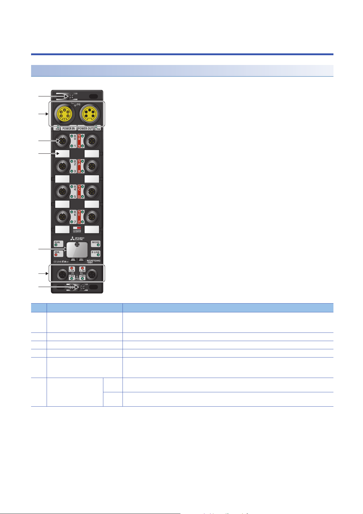
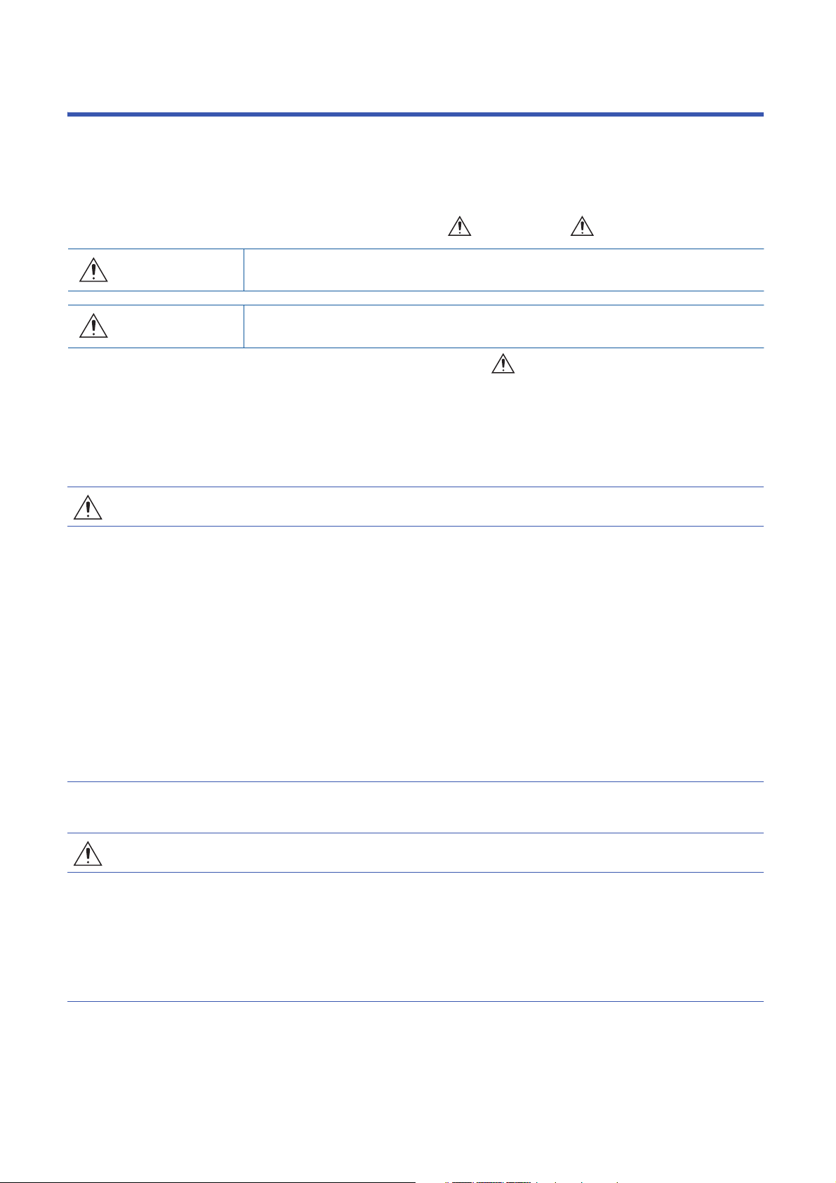
2 PART NAMES
(1)
(3)
(4)
(5)
(6)
(1)
(2)
Part names of an I/O module
This section describes part names of the I/O module.
No. Name Application
(1) FG metal fitting Metal fitting for connecting FG
(2) Power supply connectors Connectors for the module-and-sensor power supply (24VDC) and load power supply (24VDC)
(3) I/O connector Connector for I/O signals
(4) Signal label Label for describing signal names
(5) Station number setting switch Rotary switch for setting a station number or tests
(6) Communication
connectors
P1 PORT1 connector for CC-Link IE Field Network
P2 PORT2 connector for CC-Link IE Field Network
For the tightening torque of screws for the FG metal fitting, refer to the following.
Page 68 Fixing the I/O module
Page 64 Setting Switch
Page 131 Unit Test
Connect an Ethernet cable. (Page 69 Wiring of Ethernet Cable)
Connect an Ethernet cable. (Page 69 Wiring of Ethernet Cable)
16
2 PART NAMES
Page 19
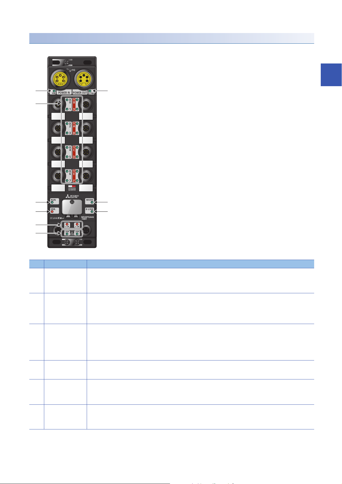
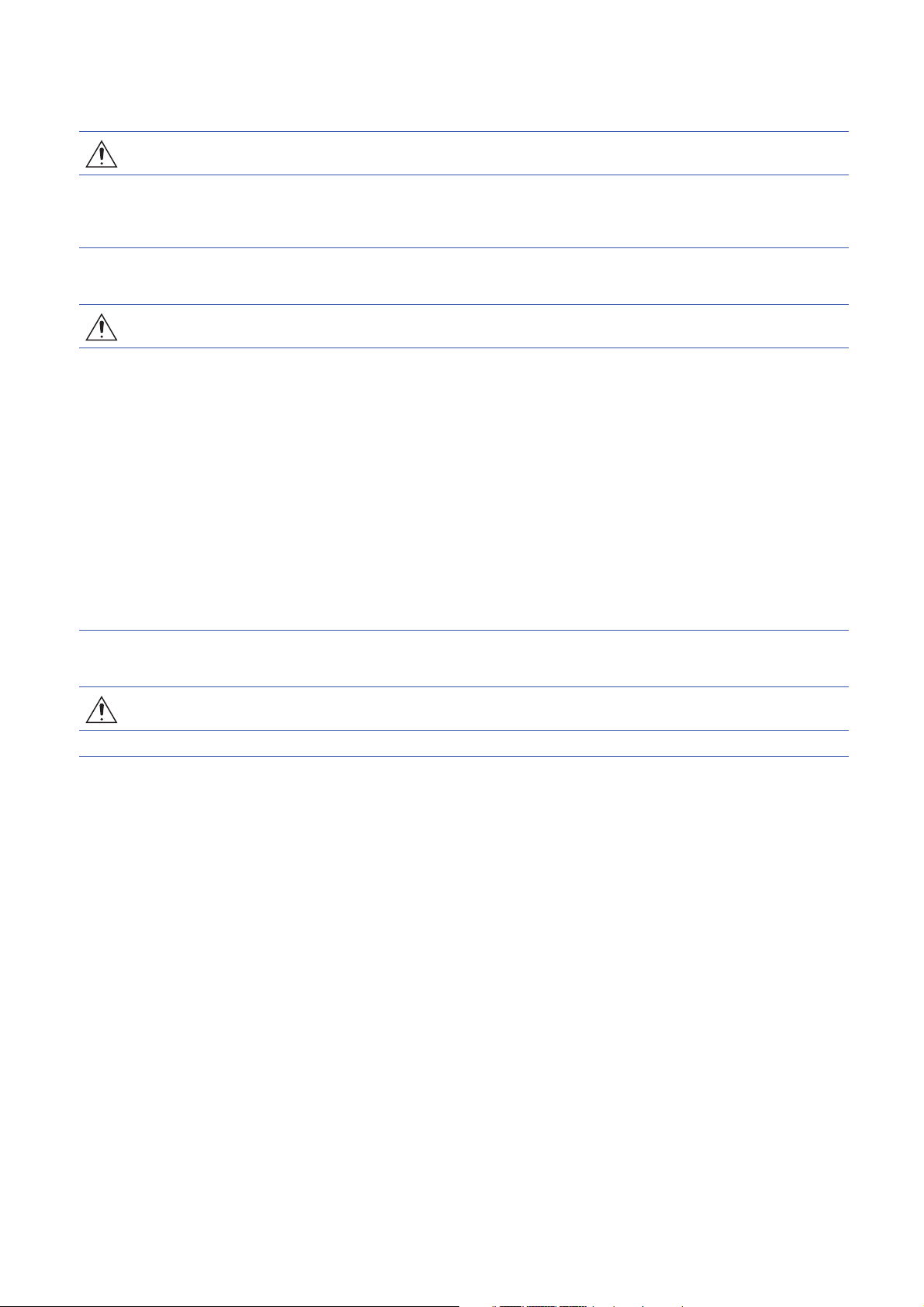
LEDs on an I/O module
(1) (2)
(4) (5)
(6) (7)
(3)
(8)
(9)
This section describes LEDs on an I/O module.
2
No. Name Description
(1) PW LED Indicates the voltage status of the module power supply.
(2) L PW LED Indicates the voltage status of the load power supply.
(3) I/O LED Indicates the on/off state of I/Os.
(4) RUN LED Indicates the operating status of the I/O module.
(5) MODE LED Indicates the mode of the I/O module.
(6) ERR. LED Indicates the error status of the I/O module.
Green: The module power supply has no voltage error.
Red: The module power supply has a voltage error.
Off: The module power supply is off or has a voltage error.
Green: The load power supply has no voltage error.
Red: The load power supply has a voltage error.
Off: The load power supply is off or has a voltage error.
The NZ2GF12A4-16D and NZ2GF12A4-16DE have no L PW LED.
Green: I/O is on.
Red: Error (short-circuit detection or power supply error)
Off: I/O is off.
For details on the short-circuit detection, refer to the following.
Page 93 Short-Circuit Detection Function
On: Operating normally.
Off: Error
On: Online
Flashing: Unit test mode
Off: The unit test is completed.
On: A module error has occurred.
Flashing: A minor error has occurred.
Off: Operating normally.
2 PART NAMES
17
Page 20

No. Name Description
(7) D LINK LED Indicates the data link status of the I/O module.
(8) L ER LED Indicates the status of each port.
(9) LINK LED
*1
On: Data link in operation (cyclic transmission in progress)
Flashing: Data link in operation (cyclic transmission stopped)
Off: Data link not performed
On: Module received abnormal data, or module performing loopback
Off: Module received normal data, or module not performing loopback
Indicates the link status.
On: Linkup in progress
Off: Linkdown in progress
*1 The LINK LED may turn on when the module is powered on. This behavior does not indicate an error.
I/O module status and LED status
The following table lists the correspondence between the I/O module status and the LED status.
I/O module status Data link status LED status
PW LED RUN LED MODE LED ERR. LED D LINK LED
Disconnected Disconnection On On On Off Off
Data link in operation Data link in operation On On On Off On
Reserved station setting in
progress
Data link stop Cyclic stop On On On Off Flashing
Unit test In progress On On Flashing Off Off
Normal
completion
Abnormal
completion
Communication error Cyclic stop On On On Off Flashing
Error Major error On Off
Moderate
error
Warning Minor error On On
Power supply voltage error
detection
Cyclic stop On On On Off Flashing
On On Off Off Off
On On Off On Off
On On
On
*4
On On On On
*1
*1
*1
*3 *2
On
On
Flashing
*2
*2
*1 Either of On or Off.
*2 Either of On, Flashing, or Off.
*3 When the module is failed, the LED may not turn on.
*4 When a power supply voltage error is detected, the LED turns on in red. (When the module is in the status other than that, the LED turns
on in green.)
18
2 PART NAMES
Page 21
3 SPECIFICATIONS
This chapter describes the specifications of the I/O module.
3.1 General Specifications
Item Specifications
Operating ambient
temperature
Storage ambient
temperature
Operating ambient
humidity
Storage ambient
humidity
Vibration resistance Compliant with JIS
Shock resistance Compliant with JIS B 3502 and IEC 61131-2 (147m/, 3 times each in X, Y, and Z directions)
Operating atmosphere No corrosive gases
Operating altitude
Installation location Inside/outside a control panel
Overvoltage category
Pollution degree
Equipment class Class
*1 Only when all necessary waterproof connectors and caps have been installed and the station number setting switch cover has been
properly tightened with a screw, the module conforms to IP67. For the tightening torque range of the screw for the station number setting
switch cover, refer to the following.
Page 65 Tightening torque
*2 Do not use or store the I/O module under pressure higher than the atmospheric pressure of altitude 0m. Doing so may cause
malfunction. When using the I/O module under pressure, please consult your local Mitsubishi representative.
*3 This indicates the section of the power supply to which the equipment is assumed to be connected between the public electrical power
distribution network and the machinery within premises.
Category applies to equipment for which electrical power is supplied from fixed facilities. The surge voltage withstand level for the
equipment with the rated voltage of 300V or less is 2500V.
*4 This index indicates the degree to which conductive material is generated in terms of the environment in which the equipment is used.
Pollution degree 2 is when only non-conductive pollution occurs. A temporary conductivity caused by condensing must be expected
occasionally.
0 to 55
-25 to 75
Conforming to IP67
5 to 95%RH, non-condensing
B 3502 and IEC
61131-2
*2
0 to 2000m
*3
or less
*4
2 or less
*1
Under intermittent
vibration
Under continuous
vibration
Frequency Constant
acceleration
5 to 8.4Hz 3.5mm 10 times each in X,
8.4 to 150Hz 9.8m/
5 to 8.4Hz 1.75mm
8.4 to 150Hz 4.9m/
Half amplitude Number of sweeps
Y, and Z directions
3
To use the I/O module complying with the EMC Directive, refer to "EMC and Low Voltage Directives" in this
manual. ( Page 166 EMC and Low Voltage Directives)
3 SPECIFICATIONS
3.1 General Specifications
19
Page 22

3.2 I/O Module Specifications
Input module
NZ2GF12A4-16D DC input module
Item NZ2GF12A4-16D
Station type Remote device station
Number of input points 16 points
Rated input voltage 24VDC (ripple rate: 5% or less) (Allowable voltage range: 20.4 to 28.8VDC)
Rated input current 7mA TYP. (for 24VDC)
Isolation method Non-isolation
Max. number of simultaneous input points 100%
ON voltage/ON current 15VDC or more/3.5mA or more
OFF voltage/OFF current 8VDC or less/1.7mA or less
Input resistance 3.3k
Input response time OFF ON 0ms/0.5ms/1ms/1.5ms/5ms/10ms/20ms/70ms
ON OFF
Input type Positive common (sink type)
Withstand voltage 500VAC for 1 minute between all DC external terminals and the ground
Insulation resistance 10M or higher between all DC external terminals and ground (500VDC insulation resistance tester)
Protection degree IP67
Wiring method for common 16 points/common (2- to 4-wire, waterproof connector type)
External interface Module power supply
Applicable waterproof
connector
Cyclic transmission RX/RY points 16 points
Communication cable An Ethernet cable that meets the 1000BASE-T standard:
Module power supply Voltage 24VDC (ripple rate: 5% or less) (Allowable voltage range: 20.4 to 28.8VDC)
Short-circuit detection current of sensor power
supply
Weight 0.72kg
part
I/O part M12 waterproof connector, 5 pins, female, A-code
Communication part M12 waterproof connector, 8 pins, female, X-code
For power supply Page 14 Recommended Connector List
For I/O
Y-branch connector
for I/O
For communications
RWr/RWw points 12 points
Current 300mA or less (24VDC, all points ON)
(Initial setting: 10ms)
7/8" waterproof connector, 5 pins, male (IN)/female (OUT)
Category 5e or higher (double shielded, STP), straight cable
400mA or more/input connector
20
The processing time of the remote device station (input) is the time period for internal processing of the
remote device station (input). The value of the processing time of the remote device station (input) is used in
the calculation for the delay time of the cyclic transmission from the remote device station (input) to the master
station (RX/RWr). Calculate the processing time of the remote device station (input) by the following formula.
• The processing time of the remote device station (input) = The input response time + The internal
processing time (0.2ms)
For the delay time of the cyclic transmission from the remote device station (input) to the master station (RX/
RWr), refer to the following.
User's manual for the master/local module used
3 SPECIFICATIONS
3.2 I/O Module Specifications
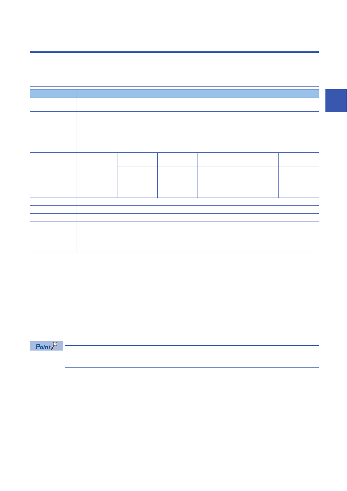
Page 23
External connection
I/O POWER CABLE(IN)
UNIT POWER CABLE(IN)
POWER
IN
POWER
OUT
4
2
1
3
5
I/O POWER CABLE(OUT)
UNIT POWER CABLE(OUT)
+24V(UNIT)
24G(UNIT)
FG
+24V (LOA D)
24G(LOAD)
4
2
3
5
1
4
2
3
5
1
+24V(UNIT)
24G(UNIT)
FG
+24V (LOA D)
24G(LOAD)
4
2
3
5
1
4
2
3
5
1
4
2
1
3
5
4
2
1
3
5
Internal
circuit
Load power supply
Non-insulated
Connector for power supply
Power supply for
module and sensor
Signal namePin No.
Connector for power supply
Signal namePin No.
4-wire sensor (sink output)
3-wire sensor (sink output)
2-wire sensor (sink output)
Detection
circuit
Detection
circuit
Detection
circuit
(2)
(3)
(1)
(4)
(5)
(4)
(3)
(5)
(2)
(1)
Power supply connectors
3
Pin number Signal name Pin number Signal name
7/8" connector
Male (IN)
(1) 24G (LOAD) 7/8" connector
(2) 24G (UNIT) (2) 24G (UNIT)
Female (OUT)
(1) 24G (LOAD)
(3) FG (3) FG
(4) +24V (UNIT) (4) +24V (UNIT)
(5) +24V (LOAD) (5) +24V (LOAD)
3 SPECIFICATIONS
3.2 I/O Module Specifications
21
Page 24

I/O connectors
(2)
(3)
(5)
(1)
(4)
Pin number Signal name Pin number Signal name
X0
X1
X2
X3
X4
X5
X6
X7
(1) +24V (UNIT) X8
(2) X1 (2) X9
(3) 24G (UNIT) (3) 24G (UNIT)
(4) X0 (4) X8
(5) FG (5) FG
(1) +24V (UNIT) XA
(2) X3 (2) XB
(3) 24G (UNIT) (3) 24G (UNIT)
(4) X2 (4) XA
(5) FG (5) FG
(1) +24V (UNIT) XC
(2) X5 (2) XD
(3) 24G (UNIT) (3) 24G (UNIT)
(4) X4 (4) XC
(5) FG (5) FG
(1) +24V (UNIT) XE
(2) X7 (2) XF
(3) 24G (UNIT) (3) 24G (UNIT)
(4) X6 (4) XE
(5) FG (5) FG
X9
XB
XD
XF
(1) +24V (UNIT)
(1) +24V (UNIT)
(1) +24V (UNIT)
(1) +24V (UNIT)
22
3 SPECIFICATIONS
3.2 I/O Module Specifications
Page 25

NZ2GF12A4-16DE DC input module
Item NZ2GF12A4-16DE
Station type Remote device station
Number of input points 16 points
Rated input voltage 24VDC (ripple rate: 5% or less) (Allowable voltage range: 20.4 to 28.8VDC)
Rated input current 7mA TYP. (for 24VDC)
Isolation method Non-isolation
Max. number of simultaneous input points 100%
ON voltage/ON current 15VDC or more/3.5mA or more
OFF voltage/OFF current 8VDC or less/1.7mA or less
Input resistance 3.3k
Input response time OFF ON 0ms/0.5ms/1ms/1.5ms/5ms/10ms/20ms/70ms
ON OFF
Input type Negative common (source type)
Withstand voltage 500VAC for 1 minute between all DC external terminals and the ground
Insulation resistance 10M or higher between all DC external terminals and ground (500VDC insulation resistance tester)
Protection degree IP67
Wiring method for common 16 points/common (2- to 4-wire, waterproof connector type)
External interface Module power supply
part
I/O part M12 waterproof connector, 5 pins, female, A-code
Communication part M12 waterproof connector, 8 pins, female, X-code
Applicable waterproof
connector
Cyclic transmission RX/RY points 16 points
Communication cable An Ethernet cable that meets the 1000BASE-T standard:
Module power supply Voltage 24VDC (ripple rate: 5% or less) (Allowable voltage range: 20.4 to 28.8VDC)
Short-circuit detection current of sensor power
supply
Weight 0.71kg
For power supply Page 14 Recommended Connector List
For I/O
Y-branch connector
for I/O
For communications
RWr/RWw points 12 points
Current 220mA or less (24VDC, all points ON)
(Initial setting: 10ms)
7/8" waterproof connector, 5 pins, male (IN)/female (OUT)
Category 5e or higher (double shielded, STP), straight cable
400mA or more/input connector
3
3 SPECIFICATIONS
3.2 I/O Module Specifications
23
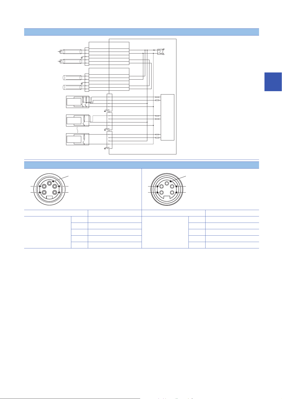
Page 26
External connection
I/O POWER CABLE(IN)
UNIT POWER CABLE(IN)
POWER
IN
POWER
OUT
4
2
1
3
5
I/O POWER CABLE(OUT)
UNIT POWER CABLE(OUT)
+24V(UNIT)
24G(UNIT)
FG
+24V (LOA D)
24G(LOAD)
4
2
3
5
1
4
2
3
5
1
+24V(UNIT)
24G(UNIT)
FG
+24V (LOA D)
24G(LOAD)
4
2
3
5
1
4
2
3
5
1
4
2
1
3
5
4
2
1
3
5
Internal
circuit
Load power supply
Non-insulated
Connector for power supply
Power supply for
module and sensor
Signal namePin No.
Connector for power supply
Signal namePin No.
4-wire sensor (source output)
3-wire sensor (source output)
2-wire sensor (source output)
Detection
circuit
Detection
circuit
Detection
circuit
(2)
(3)
(1)
(4)
(5)
(4)
(3)
(5)
(2)
(1)
Power supply connectors
Pin number Signal name Pin number Signal name
7/8" connector
Male (IN)
24
3 SPECIFICATIONS
3.2 I/O Module Specifications
(1) 24G (LOAD) 7/8" connector
(2) 24G (UNIT) (2) 24G (UNIT)
Female (OUT)
(1) 24G (LOAD)
(3) FG (3) FG
(4) +24V (UNIT) (4) +24V (UNIT)
(5) +24V (LOAD) (5) +24V (LOAD)
Page 27

I/O connectors
(2)
(3)
(5)
(1)
(4)
Pin number Signal name Pin number Signal name
X0
X1
X2
X3
X4
X5
X6
X7
(1) +24V (UNIT) X8
(2) X1 (2) X9
(3) 24G (UNIT) (3) 24G (UNIT)
(4) X0 (4) X8
(5) FG (5) FG
(1) +24V (UNIT) XA
(2) X3 (2) XB
(3) 24G (UNIT) (3) 24G (UNIT)
(4) X2 (4) XA
(5) FG (5) FG
(1) +24V (UNIT) XC
(2) X5 (2) XD
(3) 24G (UNIT) (3) 24G (UNIT)
(4) X4 (4) XC
(5) FG (5) FG
(1) +24V (UNIT) XE
(2) X7 (2) XF
(3) 24G (UNIT) (3) 24G (UNIT)
(4) X6 (4) XE
(5) FG (5) FG
X9
XB
XD
XF
(1) +24V (UNIT)
(1) +24V (UNIT)
(1) +24V (UNIT)
(1) +24V (UNIT)
3
3 SPECIFICATIONS
3.2 I/O Module Specifications
25
Page 28

Output module
NZ2GF12A2-16T transistor output module
Item NZ2GF12A2-16T
Station type Remote device station
Number of output points 16 points
Rated load voltage 12/24VDC (ripple rate: 5% or less) (Allowable voltage range: 10.2 to 28.8VDC)
Max. load current 2A/point, 8A/common
Isolation method Digital isolator isolation
Max. inrush current Current is limited by the overload protection function.
Leakage current at OFF 0.1mA or less
Max. voltage drop at ON 0.3VDC (TYP.) 0.5A, 0.6VDC (MAX.) 0.5A
Output response time OFF ON 0.5ms or less
ON OFF 1.5ms or less (resistance load)
Surge suppressor Zener diode
Output type Sink type
Withstand voltage 500VAC for 1 minute between all DC external terminals and the ground
Insulation resistance 10M or higher between all DC external terminals and ground (500VDC insulation resistance tester)
Protection degree IP67
Wiring method for common 16 points/common (2-wire, waterproof connector type)
Protection function Overload protection
External interface Module power supply
Applicable waterproof
connector
Cyclic transmission RX/RY points 16 points
Communication cable An Ethernet cable that meets the 1000BASE-T standard:
Module power supply Voltage 24VDC (ripple rate: 5% or less) (Allowable voltage range: 20.4 to 28.8VDC)
Short-circuit detection current 6.5A or more/point
Weight 0.71kg
function
Overheat protection
function
part
I/O part M12 waterproof connector, 5 pins, female, A-code
Communication part M12 waterproof connector, 8 pins, female, X-code
For power supply Page 14 Recommended Connector List
For I/O
Y-branch connector
for I/O
For communications
RWr/RWw points 12 points
Current 240mA or less (24VDC, all points ON)
Limited current when detecting overcurrent: 6.5A or more/point
Activated to each point.
Activated to each point.
7/8" waterproof connector, 5 pins, male (IN)/female (OUT)
Category 5e or higher (double shielded, STP), straight cable
26
The processing time of the remote device station (output) is the time period for internal processing of the
remote device station (output). The value of the processing time of the remote device station (output) is used
in the calculation for the delay time of the cyclic transmission from the master station (RY/RWw) to the remote
device station (output). Calculate the processing time of the remote device station (output) by the following
formula.
• The processing time of the remote device station (output) = The output response time (1.5ms) + The
internal processing time (0.2ms) = 1.7ms
For the delay time of the cyclic transmission from the master station (RY/RWw) to the remote device station
(output), refer to the following.
User's manual for the master/local module used
3 SPECIFICATIONS
3.2 I/O Module Specifications
Page 29
External connection
I/O POWER CABLE(IN)
UNIT POWER CABLE(IN)
POWER
IN
POWER
OUT
I/O POWER CABLE(OUT)
UNIT POWER CABLE(OUT)
+24V(UNIT)
24G(UNIT)
FG
+24V (LOA D)
24G(LOAD)
4
2
3
5
1
4
2
3
5
1
+24V(UNIT)
24G(UNIT)
FG
+24V (LOA D)
24G(LOAD)
4
2
3
5
1
4
2
3
5
1
4
2
1
3
5
4
2
1
3
5
Load power supply
Non-insulated
Non-insulated
Connector for power supply
Power supply for
module and sensor
Signal namePin No.
Connector for power supply
Signal namePin No.
Internal
circuit
Digital
isolator
Load
Load
Load
Load
(2)
(3)
(1)
(4)
(5)
(4)
(3)
(5)
(2)
(1)
Power supply connectors
3
Pin number Signal name Pin number Signal name
7/8" connector
Male (IN)
(1) 24G (LOAD) 7/8" connector
(2) 24G (UNIT) (2) 24G (UNIT)
Female (OUT)
(1) 24G (LOAD)
(3) FG (3) FG
(4) +24V (UNIT) (4) +24V (UNIT)
(5) +24V (LOAD) (5) +24V (LOAD)
3 SPECIFICATIONS
3.2 I/O Module Specifications
27
Page 30

I/O connectors
(2)
(3)
(5)
(1)
(4)
Pin number Signal name Pin number Signal name
Y0
Y1
Y2
Y3
Y4
Y5
Y6
Y7
(1) +24V (LOAD) Y8
(2) Y1 (2) Y9
(3) Empty (3) Empty
(4) Y0 (4) Y8
(5) FG (5) FG
(1) +24V (LOAD) YA
(2) Y3 (2) YB
(3) Empty (3) Empty
(4) Y2 (4) YA
(5) FG (5) FG
(1) +24V (LOAD) YC
(2) Y5 (2) YD
(3) Empty (3) Empty
(4) Y4 (4) YC
(5) FG (5) FG
(1) +24V (LOAD) YE
(2) Y7 (2) YF
(3) Empty (3) Empty
(4) Y6 (4) YE
(5) FG (5) FG
Y9
YB
YD
YF
(1) +24V (LOAD)
(1) +24V (LOAD)
(1) +24V (LOAD)
(1) +24V (LOAD)
28
3 SPECIFICATIONS
3.2 I/O Module Specifications
Page 31

Derating chart
Y
(55,4)
9
8
7
6
5
4
3
2
1
0
0 102030405055
X
(55,1)
(35, 2)
(35, 8)
3
X: Ambient temperature ()
Y: Output current (A)
●: Output current per point
: Output current per common
3.2 I/O Module Specifications
3 SPECIFICATIONS
29
Page 32

NZ2GF12A2-16TE transistor output module
Item NZ2GF12A2-16TE
Station type Remote device station
Number of output points 16 points
Rated load voltage 12/24VDC (ripple rate: 5% or less) (Allowable voltage range: 10.2 to 28.8VDC)
Max. load current 2A/point, 8A/common
Isolation method Digital isolator isolation
Max. inrush current Current is limited by the overload protection function.
Leakage current at OFF 0.1mA or less
Max. voltage drop at ON 0.5VDC (TYP.) 0.5A, 0.8VDC (MAX.) 0.5A
Output response time OFF ON 0.5ms or less
ON OFF 1.5ms or less (resistance load)
Surge suppressor Zener diode
Output type Source type
Withstand voltage 500VAC for 1 minute between all DC external terminals and the ground
Insulation resistance 10M or higher between all DC external terminals and ground (500VDC insulation resistance tester)
Protection degree IP67
Wiring method for common 16 points/common (2-wire, waterproof connector type)
Protection function Overload protection
function
Overheat protection
function
External interface Module power supply
Applicable waterproof
connector
Cyclic transmission RX/RY points 16 points
Communication cable An Ethernet cable that meets the 1000BASE-T standard:
Module power supply Voltage 24VDC (ripple rate: 5% or less) (Allowable voltage range: 20.4 to 28.8VDC)
Short-circuit detection current 6.5A or more/point
Weight 0.70kg
part
I/O part M12 waterproof connector, 5 pins, female, A-code
Communication part M12 waterproof connector, 8 pins, female, X-code
For power supply Page 14 Recommended Connector List
For I/O
Y-branch connector
for I/O
For communications
RWr/RWw points 12 points
Current 230mA or less (24VDC, all points ON)
Limited current when detecting overcurrent: 6.5A or more/point
Activated to each point.
Activated to each point.
7/8" waterproof connector, 5 pins, male (IN)/female (OUT)
Category 5e or higher (double shielded, STP), straight cable
30
3 SPECIFICATIONS
3.2 I/O Module Specifications
Page 33

External connection
I/O POWER CABLE(IN)
UNIT POWER CABLE(IN)
POWER
IN
POWER
OUT
I/O POWER CABLE(OUT)
UNIT POWER CABLE(OUT)
+24V(UNIT)
24G(UNIT)
FG
+24V (LOA D)
24G(LOAD)
4
2
3
5
1
4
2
3
5
1
+24V(UNIT)
24G(UNIT)
FG
+24V (LOA D)
24G(LOAD)
4
2
3
5
1
4
2
3
5
1
4
2
1
3
5
4
2
1
3
5
Load power supply
Non-insulated
Non-insulated
Connector for power supply
Power supply for
module and sensor
Signal namePin No.
Connector for power supply
Signal namePin No.
Internal
circuit
Digital
isolator
Load
Load
Load
Load
(2)
(3)
(1)
(4)
(5)
(4)
(3)
(5)
(2)
(1)
Power supply connectors
3
Pin number Signal name Pin number Signal name
7/8" connector
Male (IN)
(1) 24G (LOAD) 7/8" connector
(2) 24G (UNIT) (2) 24G (UNIT)
Female (OUT)
(1) 24G (LOAD)
(3) FG (3) FG
(4) +24V (UNIT) (4) +24V (UNIT)
(5) +24V (LOAD) (5) +24V (LOAD)
3 SPECIFICATIONS
3.2 I/O Module Specifications
31
Page 34

I/O connectors
(2)
(3)
(5)
(1)
(4)
Pin number Signal name Pin number Signal name
Y0
Y1
Y2
Y3
Y4
Y5
Y6
Y7
(1) Empty Y8
(2) Y1 (2) Y9
(3) 24G (LOAD) (3) 24G (LOAD)
(4) Y0 (4) Y8
(5) FG (5) FG
(1) Empty YA
(2) Y3 (2) YB
(3) 24G (LOAD) (3) 24G (LOAD)
(4) Y2 (4) YA
(5) FG (5) FG
(1) Empty YC
(2) Y5 (2) YD
(3) 24G (LOAD) (3) 24G (LOAD)
(4) Y4 (4) YC
(5) FG (5) FG
(1) Empty YE
(2) Y7 (2) YF
(3) 24G (LOAD) (3) 24G (LOAD)
(4) Y6 (4) YE
(5) FG (5) FG
Y9
YB
YD
YF
(1) Empty
(1) Empty
(1) Empty
(1) Empty
32
3 SPECIFICATIONS
3.2 I/O Module Specifications
Page 35

Derating chart
Y
(55,4)
9
8
7
6
5
4
3
2
1
0
0 102030405055
X
(55,1)
(35, 2)
(35, 8)
3
X: Ambient temperature ()
Y: Output current (A)
●: Output current per point
: Output current per common
3.2 I/O Module Specifications
3 SPECIFICATIONS
33
Page 36

I/O combined module
NZ2GF12A42-16DT DC input transistor output module
Item NZ2GF12A42-16DT
Input specifications Output specifications
Station type Remote device station
Number of input points 8 points
Rated input voltage 24VDC (ripple rate: 5% or less) (Allowable voltage
Rated input current 7mA TYP. (for 24VDC)
Isolation method Non-isolation
Max. number of simultaneous input points 100%
ON voltage/ON current 15VDC or more/3.5mA or more
OFF voltage/OFF current 8VDC or less/1.7mA or less
Input resistance 3.3k
Input response time
Input type Positive common (sink type)
Short-circuit detection current of sensor power
supply
Number of output points 8 points
Rated load voltage 12/24VDC (ripple rate: 5% or less) (Allowable
Max. load current 2A/point, 8A/common
Isolation method Digital isolator isolation
Max. inrush current Current is limited by the overload protection function.
Leakage current at OFF 0.1mA or less
Max. voltage drop at ON 0.3VDC (TYP.) 0.5A, 0.6VDC (MAX.) 0.5A
Output response
*2
time
Surge suppressor Zener diode
Output type Sink type
Protection function Overload protection
Short-circuit detection current 6.5A or more/point
Withstand voltage 500VAC for 1 minute between all DC external terminals and the ground
Insulation resistance 10M or higher between all DC external terminals and ground (500VDC insulation resistance tester)
Protection degree IP67
Wiring method for common 8 points/common (2- to 4-wire, waterproof connector
External interface Module power supply
Applicable waterproof
connector
Cyclic transmission RX/RY points 16 points
*1
OFF ON 0ms/0.5ms/1ms/1.5ms/5ms/10ms/20ms/70ms
ON OFF
OFF ON 0.5ms or less
ON OFF 1.5ms or less (resistance load)
function
Overheat protection
function
part
I/O part M12 waterproof connector, 5 pins, female, A-code
Communication part M12 waterproof connector, 8 pins, female, X-code
For power supply Page 14 Recommended Connector List
For I/O
Y-branch connector
for I/O
For communications
RWr/RWw points 12 points
range: 20.4 to 28.8VDC)
(Initial setting: 10ms)
400mA or more/input connector
voltage range: 10.2 to 28.8VDC)
Limited current when detecting overcurrent: 6.5A or
more/point
Activated to each point.
Activated to each point.
8 points/common (2-wire, waterproof connector type)
type)
7/8" waterproof connector, 5 pins, male (IN)/female (OUT)
34
3 SPECIFICATIONS
3.2 I/O Module Specifications
Page 37

Item NZ2GF12A42-16DT
Input specifications Output specifications
Communication cable An Ethernet cable that meets the 1000BASE-T standard:
Category 5e or higher (double shielded, STP), straight cable
Module power supply Voltage 24VDC (ripple rate: 5% or less) (Allowable voltage range: 20.4 to 28.8VDC)
Current 240mA or less (24VDC, all points ON)
Weight 0.72kg
*1 For how to calculate the processing time of the remote device station (input), refer to the point in the following.
Page 20 NZ2GF12A4-16D DC input module
*2 For how to calculate the processing time of the remote device station (output), refer to the point in the following.
Page 26 NZ2GF12A2-16T transistor output module
3
3 SPECIFICATIONS
3.2 I/O Module Specifications
35
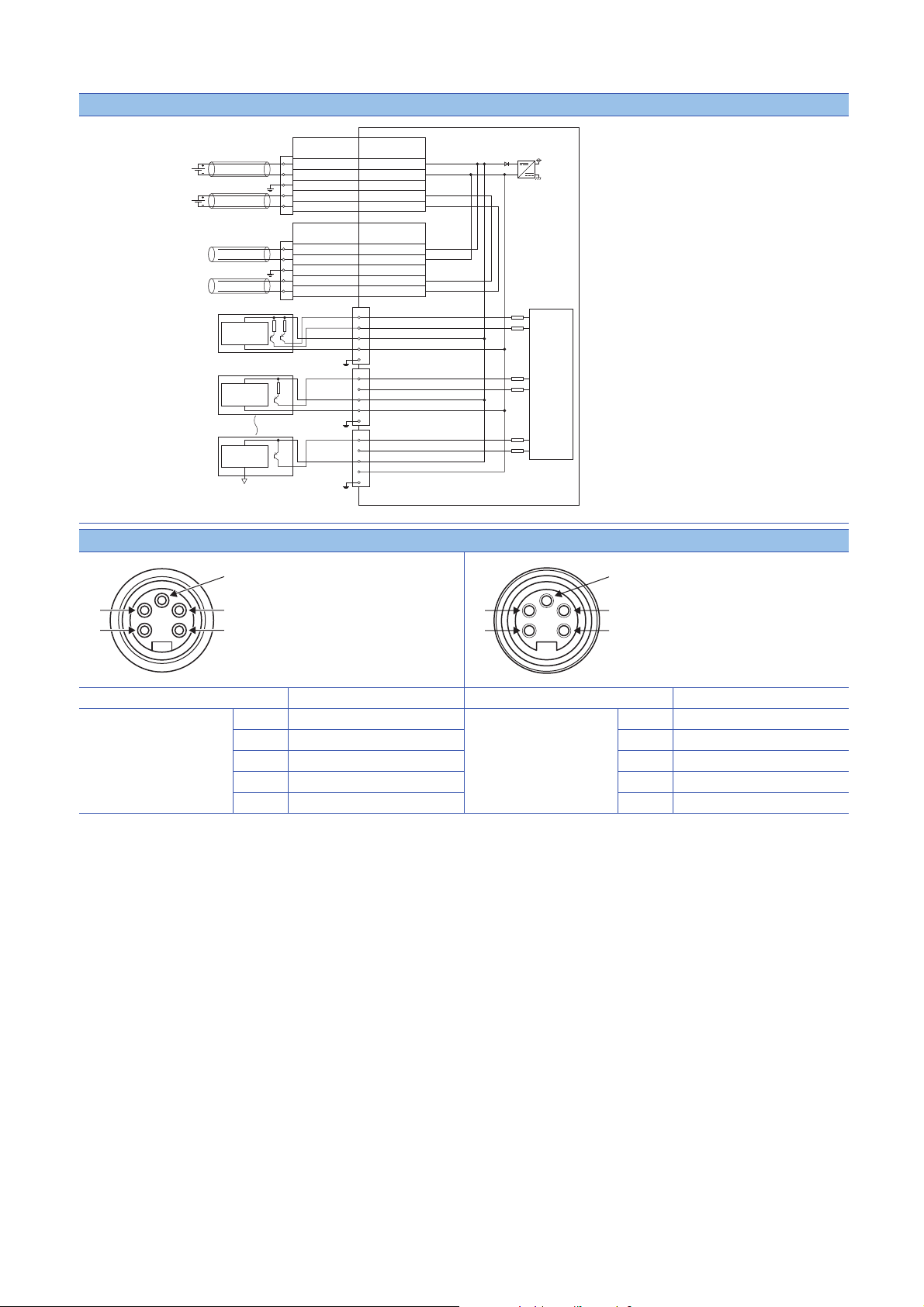
Page 38

External connection
4
2
1
3
5
4
2
1
3
5
I/O POWER CABLE(IN)
UNIT POWER CABLE(IN)
POWER
IN
POWER
OUT
I/O POWER CABLE(OUT)
UNIT POWER CABLE(OUT)
+24V(UNIT)
24G(UNIT)
FG
+24V (LOA D)
24G(LOAD)
4
2
3
5
1
4
2
3
5
1
+24V(UNIT)
24G(UNIT)
FG
+24V (LOA D)
24G(LOAD)
4
2
3
5
1
4
2
3
5
1
4
2
1
3
5
Load power supply
Non-insulated
Non-insulated
Connector for power supply
Power supply for
module and sensor
Signal namePin No.
Connector for power supply
Signal namePin No.
Internal
circuit
Digital
isolator
Load
Load
Detection
circuit
Detection
circuit
4-wire sensor (sink output)
3-wire sensor (sink output)
(2)
(3)
(1)
(4)
(5)
(4)
(3)
(5)
(2)
(1)
Power supply connectors
36
Pin number Signal name Pin number Signal name
7/8" connector
Male (IN)
(1) 24G (LOAD) 7/8" connector
(2) 24G (UNIT) (2) 24G (UNIT)
Female (OUT)
(1) 24G (LOAD)
(3) FG (3) FG
(4) +24V (UNIT) (4) +24V (UNIT)
(5) +24V (LOAD) (5) +24V (LOAD)
3 SPECIFICATIONS
3.2 I/O Module Specifications
Page 39

I/O connectors
(2)
(3)
(5)
(1)
(4)
Pin number Signal name Pin number Signal name
X0
X1
X2
X3
X4
X5
X6
X7
(1) +24V (UNIT) Y8
(2) X1 (2) Y9
(3) 24G (UNIT) (3) Empty
(4) X0 (4) Y8
(5) FG (5) FG
(1) +24V (UNIT) YA
(2) X3 (2) YB
(3) 24G (UNIT) (3) Empty
(4) X2 (4) YA
(5) FG (5) FG
(1) +24V (UNIT) YC
(2) X5 (2) YD
(3) 24G (UNIT) (3) Empty
(4) X4 (4) YC
(5) FG (5) FG
(1) +24V (UNIT) YE
(2) X7 (2) YF
(3) 24G (UNIT) (3) Empty
(4) X6 (4) YE
(5) FG (5) FG
Y9
YB
YD
YF
(1) +24V (LOAD)
(1) +24V (LOAD)
(1) +24V (LOAD)
(1) +24V (LOAD)
3
3 SPECIFICATIONS
3.2 I/O Module Specifications
37
Page 40

Derating chart
Y
(55,4)
9
8
7
6
5
4
3
2
1
0
0 102030405055
X
(55,1)
(35, 2)
(35, 8)
X: Ambient temperature ()
Y: Output current (A)
●: Output current per point
: Output current per common
38
3 SPECIFICATIONS
3.2 I/O Module Specifications
Page 41

NZ2GF12A42-16DTE DC input transistor output module
Item NZ2GF12A42-16DTE
Input specifications Output specifications
Station type Remote device station
Number of input points 8 points
Rated input voltage 24VDC (ripple rate: 5% or less) (Allowable voltage
Rated input current 7mA TYP. (for 24VDC)
Isolation method Non-isolation
Max. number of simultaneous input points 100%
ON voltage/ON current 15VDC or more/3.5mA or more
OFF voltage/OFF current 8VDC or less/1.7mA or less
Input resistance 3.3k
Input response time
Input type Negative common (source type)
Short-circuit detection current of sensor power
supply
Number of output points 8 points
Rated load voltage 12/24VDC (ripple rate: 5% or less) (Allowable
Max. load current 2A/point, 8A/common
Isolation method Digital isolator isolation
Max. inrush current Current is limited by the overload protection function.
Leakage current at OFF 0.1mA or less
Max. voltage drop at ON 0.5VDC (TYP.) 0.5A, 0.8VDC (MAX.) 0.5A
Output response
*2
time
Surge suppressor Zener diode
Output type Source type
Protection function Overload protection
Short-circuit detection current 6.5A or more/point
Withstand voltage 500VAC for 1 minute between all DC external terminals and the ground
Insulation resistance 10M or higher between all DC external terminals and ground (500VDC insulation resistance tester)
Protection degree IP67
Wiring method for common 8 points/common (2- to 4-wire, waterproof connector
External interface Module power supply
Applicable waterproof
connector
Cyclic transmission RX/RY points 16 points
Communication cable An Ethernet cable that meets the 1000BASE-T standard:
*1
OFF ON 0ms/0.5ms/1ms/1.5ms/5ms/10ms/20ms/70ms
ON OFF
OFF ON 0.5ms or less
ON OFF 1.5ms or less (resistance load)
function
Overheat protection
function
part
I/O part M12 waterproof connector, 5 pins, female, A-code
Communication part M12 waterproof connector, 8 pins, female, X-code
For power supply Page 14 Recommended Connector List
For I/O
Y-branch connector
for I/O
For communications
RWr/RWw points 12 points
range: 20.4 to 28.8VDC)
(Initial setting: 10ms)
400mA or more/input connector
voltage range: 10.2 to 28.8VDC)
Limited current when detecting overcurrent: 6.5A or
more/point
Activated to each point.
Activated to each point.
8 points/common (2-wire, waterproof connector type)
type)
7/8" waterproof connector, 5 pins, male (IN)/female (OUT)
Category 5e or higher (double shielded, STP), straight cable
3
3 SPECIFICATIONS
3.2 I/O Module Specifications
39
Page 42

Item NZ2GF12A42-16DTE
Input specifications Output specifications
Module power supply Voltage 24VDC (ripple rate: 5% or less) (Allowable voltage range: 20.4 to 28.8VDC)
Current 230mA or less (24VDC, all points ON)
Weight 0.72kg
*1 For how to calculate the processing time of the remote device station (input), refer to the point in the following.
Page 20 NZ2GF12A4-16D DC input module
*2 For how to calculate the processing time of the remote device station (output), refer to the point in the following.
Page 26 NZ2GF12A2-16T transistor output module
40
3 SPECIFICATIONS
3.2 I/O Module Specifications
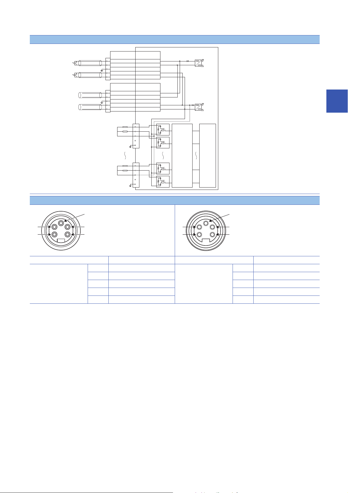
Page 43

External connection
4
2
1
3
5
4
2
1
3
5
I/O POWER CABLE(IN)
UNIT POWER CABLE(IN)
POWER
IN
POWER
OUT
I/O POWER CABLE(OUT)
UNIT POWER CABLE(OUT)
+24V(UNIT)
24G(UNIT)
FG
+24V (LOA D)
24G(LOAD)
4
2
3
5
1
4
2
3
5
1
+24V(UNIT)
24G(UNIT)
FG
+24V (LOA D)
24G(LOAD)
4
2
3
5
1
4
2
3
5
1
4
2
1
3
5
Load power supply
Non-insulated
Non-insulated
Connector for power supply
Power supply for
module and sensor
Signal namePin No.
Connector for power supply
Signal namePin No.
Internal
circuit
Digital
isolator
Load
Load
Detection
circuit
Detection
circuit
4-wire sensor (source output)
3-wire sensor (source output)
(2)
(3)
(1)
(4)
(5)
(4)
(3)
(5)
(2)
(1)
Power supply connectors
3
Pin number Signal name Pin number Signal name
7/8" connector
Male (IN)
(1) 24G (LOAD) 7/8" connector
(2) 24G (UNIT) (2) 24G (UNIT)
Female (OUT)
(1) 24G (LOAD)
(3) FG (3) FG
(4) +24V (UNIT) (4) +24V (UNIT)
(5) +24V (LOAD) (5) +24V (LOAD)
3.2 I/O Module Specifications
3 SPECIFICATIONS
41
Page 44

I/O connectors
(2)
(3)
(5)
(1)
(4)
Pin number Signal name Pin number Signal name
X0
X1
X2
X3
X4
X5
X6
X7
(1) +24V (UNIT) Y8
(2) X1 (2) Y9
(3) 24G (UNIT) (3) 24G (LOAD)
(4) X0 (4) Y8
(5) FG (5) FG
(1) +24V (UNIT) YA
(2) X3 (2) YB
(3) 24G (UNIT) (3) 24G (LOAD)
(4) X2 (4) YA
(5) FG (5) FG
(1) +24V (UNIT) YC
(2) X5 (2) YD
(3) 24G (UNIT) (3) 24G (LOAD)
(4) X4 (4) YC
(5) FG (5) FG
(1) +24V (UNIT) YE
(2) X7 (2) YF
(3) 24G (UNIT) (3) 24G (LOAD)
(4) X6 (4) YE
(5) FG (5) FG
Y9
YB
YD
YF
(1) Empty
(1) Empty
(1) Empty
(1) Empty
42
3 SPECIFICATIONS
3.2 I/O Module Specifications
Page 45

Derating chart
Y
(55,4)
9
8
7
6
5
4
3
2
1
0
0 102030405055
X
(55,1)
(35, 2)
(35, 8)
3
X: Ambient temperature ()
Y: Output current (A)
●: Output current per point
: Output current per common
3.2 I/O Module Specifications
3 SPECIFICATIONS
43
Page 46

3.3 Function List
This section lists the functions of I/O modules.
: Available, : Not available
Item Description Availability Reference
Input module Output module I/O combined
module
Error notification
function
Input function The ON/OFF status (X signal) of
Input OFF delay
function
Input response time
setting function
Output function The ON/OFF status (Y signal) of
Output HOLD/CLEAR
setting function
Cyclic data update
watch function
Number of ON times
integration function
Output ON/OFF
information hold
function
Power supply
monitoring function
Short-circuit detection
function
Fast logic function This function controls outputs
Initial operation setting
function
P
rotection function This function protects the internal
When an error or warning occurs, the
I/O module notifies the master station
of it using remote registers.
inputs is notified to Remote input (RX)
which is the buffer memory of the
master station.
This function turns off an X signal after
a predetermined time passed from
when an actual input becomes off
from on.
This function prevents an incorrect
input due to noise by setting the
response time until the module
recognizes an actual input as the X
signal.
outputs is controlled with Remote
output (RY) which is the buffer
memory of the master station.
When the I/O module is disconnected
from data link, or the CPU module
operating status is STOP, whether to
hold or clear the last output value can
be set.
The update intervals of cyclic data are
monitored. The last output value is
held or cleared when the cyclic
transmission stop status continues
longer than the set monitoring time.
The total number of ON times of each
output point is counted with this
function. The integration value
remains even though the output
module is powered off.
This function checks if the output has
been turned once on or off.
This function monitors the power
supply status of the module-andsensor power supply and load power
supply.
This function detects a short circuit in
each of input ports and output
channels.
according to the input status inside the
I/O combined module without
communications with the master
station. High-speed output control can
be performed with this function.
This function sets whether the initial
processing using the program is
necessary or not when the data link is
established.
circuit of the module.
Page 81 Error
Notification Function
Page 84 Input OFF
Delay Function
Page 86 Input
Response Time Setting
Function
Page 87 Output HOLD/
CLEAR Setting
Function
Page 88 Cyclic Data
Update Watch
Function
Page 89 Number of ON
Times Integration
Function
Page 91 Output ON/
OFF Information Hold
Function
Page 92 Power Supply
Monitoring Function
Page 93 Short-Circuit
Detection Function
Page 95 Fast Logic
Function
Page 98 Initial
Operation Setting
Function
Page 100 Protection
Function
44
3 SPECIFICATIONS
3.3 Function List
Page 47

Item Description Availability Reference
Input module Output module I/O combined
module
CC-Link IE Field
Network diagnostic
function
This function allows the presence or
absence of a network error to be
checked by accessing the engineering
tool connected to the CPU module.
Page 100 CC-Link IE
Field Network
Diagnostic Function
3
3 SPECIFICATIONS
3.3 Function List
45
Page 48

3.4 List of Remote I/O Signals
This section lists I/O signals for a master/local module.
The following shows an assignment example of I/O signals with the remote I/O signals of the I/O module assigned to the I/O
numbers of RX0 to RXF and RY0 to RYF.
Remote input (RX) indicates the input signal from the I/O module to the master/local module.
Remote output (RY) indicates the output signal from the master/local module to the I/O module.
The remote I/O signals of the I/O module are assigned as shown below.
Module Remote input (RX) Remote output (RY)
I/O module RX0 to RXF RY0 to RYF
Do not use any "Use prohibited" remote I/O signals. Doing so may cause an accident due to incorrect output
or malfunction.
Input module
The remote I/O signals of the input module are assigned as shown below.
Remote input Remote output
Signal direction: Input module Master/local module Signal direction: Master/local module Input module
Device number Description Device number Description
RX0 External input signal X0 RY0 Use prohibited
RX1 External input signal X1 RY1
RX2 External input signal X2 RY2
RX3 External input signal X3 RY3
RX4 External input signal X4 RY4
RX5 External input signal X5 RY5
RX6 External input signal X6 RY6
RX7 External input signal X7 RY7
RX8 External input signal X8 RY8
RX9 External input signal X9 RY9
RXA External input signal XA RYA
RXB External input signal XB RYB
RXC External input signal XC RYC
RXD External input signal XD RYD
RXE External input signal XE RYE
RXF External input signal XF RYF
46
3 SPECIFICATIONS
3.4 List of Remote I/O Signals
Page 49

Output module
The remote I/O signals of the output module are assigned as shown below.
Remote input Remote output
Signal direction: Output module Master/local module Signal direction: Master/local module Output module
Device number Description Device number Description
RX0 Use prohibited RY0 External output signal Y0
RX1 RY1 External output signal Y1
RX2 RY2 External output signal Y2
RX3 RY3 External output signal Y3
RX4 RY4 External output signal Y4
RX5 RY5 External output signal Y5
RX6 RY6 External output signal Y6
RX7 RY7 External output signal Y7
RX8 RY8 External output signal Y8
RX9 RY9 External output signal Y9
RXA RYA External output signal YA
RXB RYB External output signal YB
RXC RYC External output signal YC
RXD RYD External output signal YD
RXE RYE External output signal YE
RXF RYF External output signal YF
3
I/O combined module
The remote I/O signals of the I/O combined module are assigned as shown below.
Remote input Remote output
Signal direction: I/O combined module Master/local module Signal direction: Master/local module I/O combined module
Device number Description Device number Description
RX0 External input signal X0 RY0 Use prohibited
RX1 External input signal X1 RY1
RX2 External input signal X2 RY2
RX3 External input signal X3 RY3
RX4 External input signal X4 RY4
RX5 External input signal X5 RY5
RX6 External input signal X6 RY6
RX7 External input signal X7 RY7
RX8 Use prohibited RY8 External output signal Y8
RX9 RY9 External output signal Y9
RXA RYA External output signal YA
RXB RYB External output signal YB
RXC RYC External output signal YC
RXD RYD External output signal YD
RXE RYE External output signal YE
RXF RYF External output signal YF
3 SPECIFICATIONS
3.4 List of Remote I/O Signals
47
Page 50

3.5 List of Remote Register
This section lists remote registers for a master/local module.
The following shows an assignment example of remote registers with the remote registers of the I/O module assigned to the
remote registers of RWr0 to RWrB and RWw0 to RWwB.
The remote registers are assigned in station-based units.
Remote register (RWr) is the information input from the I/O module to the master/local module.
Remote register (RWw) is the information output from the master/local module to the I/O module.
For details on the remote register, refer to the following.
Page 144 Details of Remote Registers
Do not read or write data from/to any "Use prohibited" remote registers. Doing so may cause an accident due
to incorrect output or malfunction.
Input module
Remote register (RWr) Remote register (RWw)
Signal direction: Input module Master/local module Signal direction: Master/local module Input module
Device
number
RWr0 Module status area RWw0 Module operation area
RWr1 Error code RWw1 Use prohibited
RWr2 Warning code RWw2 Use prohibited
RWr3 Function selection status flag RWw3 Function selection setting flag
RWr4 Input X port status RWw4 Use prohibited
RWr5 Use prohibited RWw5 Use prohibited
RWr6 Use prohibited RWw6 Use prohibited
RWr7 Use prohibited RWw7 Use prohibited
RWr8 Use prohibited RWw8 Use prohibited
RWr9 Use prohibited RWw9 Use prohibited
RWrA Use prohibited RWwA Use prohibited
RWrB Use prohibited RWwB Use prohibited
Name Device
number
Name
48
For the output ON/OFF information hold function, refer to the following.
Page 91 Output ON/OFF Information Hold Function
3 SPECIFICATIONS
3.5 List of Remote Register
Page 51

Output module
Remote register (RWr) Remote register (RWw)
Signal direction: Output module Master/local module Signal direction: Master/local module Output module
Device
number
RWr0 Module status area RWw0 Module operation area
RWr1 Error code RWw1 Use prohibited
RWr2 Warning code RWw2 Use prohibited
RWr3 Function selection status flag RWw3 Function selection setting flag
RWr4 Use prohibited RWw4 Use prohibited
RWr5 Output Y channel status RWw5 Use prohibited
RWr6 Output Y current value Y0 to YF RWw6 Use prohibited
RWr7 Output Y ON information Y0 to YF RWw7 Output Y ON information clear request Y0 to YF
RWr8 Output Y OFF information Y0 to YF RWw8 Output Y OFF information clear request Y0 to YF
RWr9 Use prohibited RWw9 Use prohibited
RWrA Use prohibited RWwA Use prohibited
RWrB Use prohibited RWwB Use prohibited
Name Device
number
Name
For the output ON/OFF information hold function, refer to the following.
Page 91 Output ON/OFF Information Hold Function
3
I/O combined module
Remote register (RWr) Remote register (RWw)
Signal direction: I/O combined module Master/local module Signal direction: Master/local module I/O combined module
Device
number
RWr0 Module status area RWw0 Module operation area
RWr1 Error code RWw1 Use prohibited
RWr2 Warning code RWw2 Use prohibited
RWr3 Function selection status flag RWw3 Function selection setting flag
RWr4 Input X port status RWw4 Use prohibited
RWr5 Output Y channel status RWw5 Use prohibited
RWr6 Output Y current value Y8 to YF RWw6 Use prohibited
RWr7 Output Y ON information Y8 to YF RWw7 Output Y ON information clear request Y8 to YF
RWr8 Output Y OFF information Y8 to YF RWw8 Output Y OFF information clear request Y8 to YF
RWr9 Use prohibited RWw9 Use prohibited
RWrA Use prohibited RWwA Use prohibited
RWrB Use prohibited RWwB Use prohibited
Name Device
number
Name
For the output ON/OFF information hold function, refer to the following.
Page 91 Output ON/OFF Information Hold Function
3 SPECIFICATIONS
3.5 List of Remote Register
49
Page 52

3.6 List of Remote Buffer Memory
This section lists the remote buffer memory areas of the I/O module.
The remote buffer memory areas of the I/O module are assigned as shown below.
Description of a remote buffer memory area
■I/O response time setting (address: 0000H)
The following shows the description of I/O response time setting (address: 0000H) as an example.
Item Description
I/O response time setting Setting item
(address: 0000H) Remote buffer memory address
■Input OFF delay setting X (address: 0110H to 012FH)
The following shows the description of Input OFF delay setting X (address: 0110H to 012FH) as an example.
Item Description
Input OFF delay setting Setting item
X Input signal or output signal
(address: 0110H to 012FH) Remote buffer memory address
For details on the remote buffer memory, refer to the following.
Page 154 Details of Remote Buffer Memory Addresses
: Available, : Not available
Address Area Targe t Access method
Decimal Hexadecimal CC IE Field
configuration of
the engineering
tool
0 to 255 0000H to 00FFH Parameter area Station-based parameter data
256 to 511 0100H to 01FFH Module-based
512 to 767 0200H to 02FFH System area
768 to 1023 0300H to 03FFH System area
1024 to 1279 0400H to 04FFH System area
1280 to 1535 0500H to 05FFH Monitoring area Station-based monitor data
1536 to 1791 0600H to 06FFH Module-based
1792 to 2047 0700H to 07FFH System area
2048 to 2303 0800H to 08FFH System area
2304 to 2559 0900H to 09FFH System area
2560 to 4095 0A00H to 0FFFH Error history area Station-based error history data
4096 to 4351 1000H to 10FFH Module control data
4352 to 4607 1100H to 11FFH Module-based
4608 to 4863 1200H to 12FFH System area
4864 to 5119 1300H to 13FFH System area
5120 to 5375 1400H to 14FFH System area
area
parameter
data
monitor data
Station-based control data
control data
I/O module
I/O module
I/O module
*2
*2
REMFR
instruction,
REMTO
instruction
*1
*1 For the REMFR and REMTO instructions, refer to the following.
User's manual for the master/local module used
*2 For the access method, refer to the following.
Parameter area ( Page 72 Parameter Setting)
Error history area ( Page 121 Checking for the Error Codes and the Warning Codes)
50
3 SPECIFICATIONS
3.6 List of Remote Buffer Memory
Page 53

• Do not access the system area using the REMFR or REMTO instruction. Doing so may lead the module to
malfunction.
• Do not use the dedicated instruction of the REMFR and REMTO instructions to the areas later than the
above areas. If these instructions are used, the error code (0202H) is stored in Warning code (RWr2),
Warning status flag (RWr0.b12) turns on, and the ERR. LED flashes.
Parameter area (address: 0000H to 04FFH)
For the parameter area, parameters can be set by means of the CC IE Field configuration of the engineering tool, or the
REMTO instruction.
The parameter in the parameter area is backed up to the nonvolatile memory.
However, Fast logic setting Y (address: 0120H to 0127H) is not backed up. The parameter backed up to the nonvolatile
memory is read to the parameter area when the module power supply is turned off and on or the module returns from remote
reset.
For the parameters written from the parameter settings of the CC IE Field configuration of the engineering tool, the write to the
non-volatile memory is also completed at the same time. When the parameter is written using the REMTO instruction, it is
written to the nonvolatile memory when Operation condition setting request flag (RWw0.b9) is turned on. At this time, the
parameter is written to the nonvolatile memory even though it is incorrect. When the power supply is turned off and on with an
incorrect parameter written, the incorrect parameter is read from the nonvolatile memory and an error code is stored to Error
code (RWr1). Take corrective action according to the error code list. (Page 124 Error Code List)
3
3 SPECIFICATIONS
3.6 List of Remote Buffer Memory
51
Page 54

■Input module
R: Can be read from a program, W: Can be written to a program
Typ e Address Input module
Decimal Hexadecimal Name Default value
Station-based parameter
data
Module-based parameter
data
System area 512 to 1279 0200H to 04FFH System area
0 0000H Input response time setting 0005H R/W
1 0001H System area
2 0002H System area
3 0003H System area
4 0004H Initial operation setting 0001H R/W
5 to 255 0005H to 00FFH System area
256 to 271 0100H to 010FH System area
272 0110H Input OFF delay setting X0 0 R/W
273 0111H
274 0112H Input OFF delay setting X1 0 R/W
275 0113H
276 0114H Input OFF delay setting X2 0 R/W
277 0115H
278 0116H Input OFF delay setting X3 0 R/W
279 0117H
280 0118H Input OFF delay setting X4 0 R/W
281 0119H
282 011AH Input OFF delay setting X5 0 R/W
283 011BH
284 011CH Input OFF delay setting X6 0 R/W
285 011DH
286 011EH Input OFF delay setting X7 0 R/W
287 011FH
288 0120H Input OFF delay setting X8 0 R/W
289 0121H
290 0122H Input OFF delay setting X9 0 R/W
291 0123H
292 0124H Input OFF delay setting XA 0 R/W
293 0125H
294 0126H Input OFF delay setting XB 0 R/W
295 0127H
296 0128H Input OFF delay setting XC 0 R/W
297 0129H
298 012AH Input OFF delay setting XD 0 R/W
299 012BH
300 012CH Input OFF delay setting XE 0 R/W
301 012DH
302 012EH Input OFF delay setting XF 0 R/W
303 012FH
304 to 511 0130H to 01FFH System area
*1
Read/Write
*1 This value is the factory default value or the value after the initialization by Parameter area initialization command (address: 1002H).
3 SPECIFICATIONS
52
3.6 List of Remote Buffer Memory
Page 55

■Output module
R: Can be read from a program, W: Can be written to a program
Typ e Address Output module
Decimal Hexadecimal Name Default value
Station-based parameter
data
Module-based parameter
data
System area 512 to 1279 0200H to 04FFH System area
*1 This value is the factory default value or the value after the initialization by Parameter area initialization command (address: 1002H).
0 0000H System area
1 0001H Output HOLD/CLEAR setting 0000H R/W
2 0002H Cyclic data update watch time setting 0000H R/W
3 0003H System area
4 0004H Initial operation setting 0001H R/W
5 to 255 0005H to 00FFH System area
256 0100H System area
257 0101H
258 0102H Number of ON times integration function
enable Y0 to YF
259 to 511 0103H to 01FFH System area
0000H R/W
*1
Read/Write
3
3 SPECIFICATIONS
3.6 List of Remote Buffer Memory
53
Page 56

■I/O combined module
R: Can be read from a program, W: Can be written to a program
Typ e Address I/O module
Decimal Hexadecimal Name Default value
Station-based parameter
data
Module-based parameter
data
System area 512 to 1279 0200H to 04FFH System area
0 0000H Input response time setting 0005H R/W
1 0001H Output HOLD/CLEAR setting 0000H R/W
2 0002H Cyclic data update watch time setting 0000H R/W
3 0003H System area
4 0004H Initial operation setting 0001H R/W
5 to 255 0005H to 00FFH System area
256 0100H System area
257 0101H
258 0102H Number of ON times integration function
enable Y8 to YF
259 to 271 0103H to 010FH System area
272 0110H Input OFF delay setting X0 0 R/W
273 0111H
274 0112H Input OFF delay setting X1 0 R/W
275 0113H
276 0114H Input OFF delay setting X2 0 R/W
277 0115H
278 0116H Input OFF delay setting X3 0 R/W
279 0117H
280 0118H Input OFF delay setting X4 0 R/W
281 0119H
282 011AH Input OFF delay setting X5 0 R/W
283 011BH
284 011CH Input OFF delay setting X6 0 R/W
285 011DH
286 011EH Input OFF delay setting X7 0 R/W
287 011FH
288 0120H Fast logic setting Y8 0 R/W
289 0121H
290 0122H Fast logic setting Y9 0 R/W
291 0123H
292 0124H Fast logic setting YA 0 R/W
293 0125H
294 0126H Fast logic setting YB 0 R/W
295 0127H
296 to 511 0128H to 01FFH System area
0000H R/W
*1
Read/Write
*1 This value is the factory default value or the value after the initialization by Parameter area initialization command (address: 1002H).
3 SPECIFICATIONS
54
3.6 List of Remote Buffer Memory
Page 57

Monitoring area (address: 0500H to 09FFH)
■Input module
R: Can be read from a program, W: Can be written to a program
Typ e Address Input module
Decimal Hexadecimal Name Read/Write
Station-based monitor data 1280 to 1535 0500H to 05FFH System area
Module-based monitor data 1536 to 1791 0600H to 06FFH System area
System area 1792 to 2559 0700H to 09FFH System area
Default values are not determined in the monitoring area.
■Output module
R: Can be read from a program, W: Can be written to a program
Typ e Address Output module
Decimal Hexadecimal Name Read/Write
Station-based monitor data 1280 to 1535 0500H to 05FFH System area
Module-based monitor data 1536 to 1551 0600H to 060FH System area
1552 0610H Number of ON times integration value Y0 R
1553 0611H
1554 0612H Number of ON times integration value Y1 R
1555 0613H
1556 0614H Number of ON times integration value Y2 R
1557 0615H
1558 0616H Number of ON times integration value Y3 R
1559 0617H
1560 0618H Number of ON times integration value Y4 R
1561 0619H
1562 061AH Number of ON times integration value Y5 R
1563 061BH
1564 061CH Number of ON times integration value Y6 R
1565 061DH
1566 061EH Number of ON times integration value Y7 R
1567 061FH
1568 0620H Number of ON times integration value Y8 R
1569 0621H
1570 0622H Number of ON times integration value Y9 R
1571 0623H
1572 0624H Number of ON times integration value YA R
1573 0625H
1574 0626H Number of ON times integration value YB R
1575 0627H
1576 0628H Number of ON times integration value YC R
1577 0629H
1578 062AH Number of ON times integration value YD R
1579 062BH
1580 062CH Number of ON times integration value YE R
1581 062DH
1582 062EH Number of ON times integration value YF R
1583 062FH
1584 to 1791 0630H to 06FFH System area
System area 1792 to 2559 0700H to 09FFH System area
3
3 SPECIFICATIONS
3.6 List of Remote Buffer Memory
55
Page 58

Default values are not determined in the monitoring area.
■I/O combined module
R: Can be read from a program, W: Can be written to a program
Typ e Address I/O combined module
Decimal Hexadecimal Name Read/Write
Station-based monitor data 1280 to 1535 0500H to 05FFH System area
Module-based monitor data 1536 0600H System area
1537 0601H
1538 0602H Fast logic enable status Y8 to YB R
1539 to 1567 0603H to 061FH System area
1568 0620H Number of ON times integration value Y8 R
1569 0621H
1570 0622H Number of ON times integration value Y9 R
1571 0623H
1572 0624H Number of ON times integration value YA R
1573 0625H
1574 0626H Number of ON times integration value YB R
1575 0627H
1576 0628H Number of ON times integration value YC R
1577 0629H
1578 062AH Number of ON times integration value YD R
1579 062BH
1580 062CH Number of ON times integration value YE R
1581 062DH
1582 062EH Number of ON times integration value YF R
1583 062FH
1584 to 1791 0630H to 06FFH System area
System area 1792 to 2559 0700H to 09FFH System area
Default values are not determined in the monitoring area.
56
3 SPECIFICATIONS
3.6 List of Remote Buffer Memory
Page 59

Error history area (address: 0A00H to 0FFFH)
■Common to input modules, output modules, and I/O combined modules
R: Can be read from a program, W: Can be written to a program
Address Common to input modules, output modules, and I/O combined modules
Decimal Hexadecimal Name Default value
2560 0A00H Error history data 1 Error code 0000H R
2561 0A01H Order of generation 0000H R
2562 0A02H [Error time] First two digits of the
2563 0A03H [Error time] Month/Day 0000H R
2564 0A04H [Error time] Hour/Minute 0000H R
2565 0A05H [Error time] Second/00H (Fixed) 0000H R
2566 0A06H Error code details 1 0000H R
2567 0A07H Error code details 2 0000H R
2568 0A08H Error code details 3 0000H R
2569 0A09H Error code details 4 0000H R
2570 0A0AH Error code details 5 0000H R
2571 0A0BH Error code details 6 0000H R
2572 0A0CH Error code details 7 0000H R
2573 0A0DH Error code details 8 0000H R
2574 0A0EH Error code details 9 0000H R
2575 0A0FH Error code details 10 0000H R
2576 to 2591 0A10H to 0A1FH Error history data 2 Same as Error history data 1.
2592 to 2607 0A20H to 0A2FH Error history data 3 Same as Error history data 1.
2608 to 2623 0A30H to 0A3FH Error history data 4 Same as Error history data 1.
2624 to 2639 0A40H to 0A4FH Error history data 5 Same as Error history data 1.
2640 to 2655 0A50H to 0A5FH Error history data 6 Same as Error history data 1.
2656 to 2671 0A60H to 0A6FH Error history data 7 Same as Error history data 1.
2672 to 2687 0A70H to 0A7FH Error history data 8 Same as Error history data 1.
2688 to 2703 0A80H to 0A8FH Error history data 9 Same as Error history data 1.
2704 to 2719 0A90H to 0A9FH Error history data 10 Same as Error history data 1.
2720 to 2735 0AA0H to
0AAFH
2736 to 2751 0AB0H to
0ABFH
2752 to 2767 0AC0H to
0ACFH
2768 to 2783 0AD0H to
0ADFH
2784 to 2799 0AE0H to
0AEFH
2800 to 4095 0AF0H to 0FFFH System area
Error history data 11 Same as Error history data 1.
Error history data 12 Same as Error history data 1.
Error history data 13 Same as Error history data 1.
Error history data 14 Same as Error history data 1.
Error history data 15 Same as Error history data 1.
year/Last two digits of the year
0000H R
*1
Read/Write
3
*1 This value is the factory default value or the value after the initialization by Error history clear command (address: 1000H).
3 SPECIFICATIONS
3.6 List of Remote Buffer Memory
57
Page 60

Module control data area (address: 1000H to 14FFH)
■Input module
R: Can be read from a program, W: Can be written to a program
Typ e Address Input module
Decimal Hexadecimal Name Default value
Station-based control data 4096 1000H Error history clear command 0000H R/W
4097 1001H Error history clear completed 0000H R
4098 1002H Parameter area initialization command 0000H R/W
4099 1003H Parameter area initialization completed 0000H R
4100 1004H Module operation information initialization
command
4101 1005H Module operation information initialization
completed
4102 to 4351 1006H to 10FFH System area
Module-based control data 4352 to 4607 1100H to 11FFH System area
System area 4608 to 5375 1200H to 14FFH System area
0000H R/W
0000H R
*1 This is the value for when the module power supply is turned off and on or at the remote reset.
■Output module
R: Can be read from a program, W: Can be written to a program
Typ e Address Output module
Decimal Hexadecimal Name Default value
Station-based control data 4096 1000H Error history clear command 0000H R/W
4097 1001H Error history clear completed 0000H R
4098 1002H Parameter area initialization command 0000H R/W
4099 1003H Parameter area initialization completed 0000H R
4100 1004H Module operation information initialization
command
4101 1005H Module operation information initialization
completed
4102 to 4351 1006H to 10FFH System area
Module-based control data 4352 1100H Number of ON times integration value clear
request Y0 to YF
4353 1101H Number of ON times integration value clear
completed Y0 to YF
4354 to 4607 1102H to 11FFH System area
System area 4608 to 5375 1200H to 14FFH System area
0000H R/W
0000H R
0000H R/W
0000H R
*1
*1
Read/Write
Read/Write
*1 This is the value for when the module power supply is turned off and on or at the remote reset.
3 SPECIFICATIONS
58
3.6 List of Remote Buffer Memory
Page 61

■I/O combined module
R: Can be read from a program, W: Can be written to a program
Typ e Address I/O combined module
Decimal Hexadecimal Name Default value
Station-based control data 4096 1000H Error history clear command 0000H R/W
4097 1001H Error history clear completed 0000H R
4098 1002H Parameter area initialization command 0000H R/W
4099 1003H Parameter area initialization completed 0000H R
4100 1004H Module operation information initialization
command
4101 1005H Module operation information initialization
completed
4102 to 4351 1006H to 10FFH System area
Module-based control data 4352 1100H Number of ON times integration value clear
command Y8 to YF
4353 1101H Number of ON times integration value clear
completed Y8 to YF
4354 to 4607 1102H to 11FFH System area
System area 4608 to 5375 1200H to 14FFH System area
*1 This is the value for when the module power supply is turned off and on or at the remote reset.
0000H R/W
0000H R
0000H R/W
0000H R
*1
Read/Write
3
3 SPECIFICATIONS
3.6 List of Remote Buffer Memory
59
Page 62

4 PROCEDURES BEFORE OPERATION
This chapter describes the procedures before operation.
1. Station number setting
Set the station number of the I/O module with the station number setting switch.
Page 64 Station number setting with the station number setting switch
2. Wiring
Wire a power supply, an Ethernet cable, and an external device to the I/O module.
Page 68 Wiring the Power Supply
Page 69 Wiring of Ethernet Cable
3. Parameter setting and programming
Set parameters and create a program.
Page 72 Parameter Setting
Page 77 Changing the Parameter
Page 103 PROGRAMMING
*1 To replace the module, refer to the point below.
To replace the module, follow the procedure described below:
• Turn off the module power supply and remove the I/O module.
• Prepare a new I/O module and perform the procedure above from "Station number setting" to "Parameter
setting and programming". (The network parameter of the master station does not need to be set again.)
• After checking the operation, restart the control.
*1
60
4 PROCEDURES BEFORE OPERATION
Page 63

MEMO
4
4 PROCEDURES BEFORE OPERATION
61
Page 64

5 SYSTEM CONFIGURATION
This chapter describes system configuration using an I/O module.
For CC-Link IE Field Network configuration, refer to the following.
User's manual for the master/local module used
5.1 Applicable Systems
Applicable master station
When using an I/O module, use the following products as a master station.
Model First five digits of serial number
RJ71GF11-T2 (no restriction)
RJ71EN71
QJ71GF11-T2 "14102" or later
LJ71GF11-T2
QD77GF16 "14111" or later
Information on "Applicable master station" described above is the ones at the point when this manual was issued.
For latest information, please visit the website of CC-Link Partner Association.
www.cc-link.org
Ethernet cable
Use a general-purpose Ethernet cable that meets the 1000BASE-T standard.
Consider the operating environment when selecting available cables that satisfy the product specifications.
Available software
The following software is available for settings and diagnostics of the I/O module. ( Manuals of each software)
Product name Function and application
GX Works2 Software for system design, programming, debugging, and maintenance of the programmable controller.
GX Works3
Applicable profile
To use the parameter setting function of an I/O module, the profile is required.
When the latest profile of the remote I/O module is necessary, please consult your local Mitsubishi representative.
The profile is a setting file that stores information required for the start-up, operation, and maintenance of devices supporting
the CC-Link family.
A module is added to "Module List" of "CC IE Field Configuration" window by profile registration to an engineering tool. For the
profile registration, refer to the operating manual for the engineering tool used.
62
5 SYSTEM CONFIGURATION
5.1 Applicable Systems
Page 65

MEMO
5
5 SYSTEM CONFIGURATION
5.1 Applicable Systems
63
Page 66

6 INSTALLATION AND WIRING
This chapter describes the installation and wiring of the I/O module.
6.1 Setting Switch
Station number setting with the station number setting switch
Setting procedure
Set a station number with the station number setting switch on the front of the module. The setting value of the station number
becomes valid when the module is powered on. Thus, set the station number when the module is powered off.
1. Loosen the screw for the station number setting switch
cover with a screwdriver and open the cover.
2. Set a station number.
• The hundreds and tens places of the station number are set with x10.
• The ones place of the station number is set with x1.
*1
3. After setting the station number with the station number
setting switch, always close the station number setting
switch cover and tighten the screw for the cover with a
*2
screwdriver.
not been tightened properly, waterproof performance is
lost.
*1 When operating the station number setting switch, use a flathead screwdriver with 3.5mm or less width of the tip.
*2 For the tightening torque range of the screw for the station number setting switch cover, refer to the following.
Page 65 Tightening torque
When the cover is open or the screw has
64
6 INSTALLATION AND WIRING
6.1 Setting Switch
Page 67

Ex.
To set the station to 115, set the switch as shown below.
Setting range
Set the station number from 1 to 120. Setting the value other than 1 to 120 causes a communication error and the D LINK
LED flashes.
• Do not change the station number setting switch while the module is powered on. Changing the station
number setting switch causes a minor error and flashes the ERR. LED. Returning the station number setting
switches to the previous setting eliminates the error after five seconds and turns off the ERR. LED.
• Do not set a station number duplicated with other station numbers. If the station number is duplicated, a
communication error occurs and the D LINK LED does not turn on.
Tightening torque
Tighten the screw for the station number setting switch cover within the following tightening torque range.
Screw type Tightening torque range
Station number setting switch cover (M3 screw) 0.43 to 0.57Nm
6
• Do not put oil on the screw. Failure to do so may damage the screw.
• Tighten the screw with an applicable screwdriver. Tightening it with an inapplicable screwdriver may
damage the screw.
6 INSTALLATION AND WIRING
6.1 Setting Switch
65
Page 68

6.2 Installation Environment and Installation Position
Installation environment
Installation location
Do not install the I/O module to the place where:
• Ambient temperature is outside the range of 0 to 55;
• IP67 is not satisfied;
• Condensation occurs due to rapid temperature change;
• Corrosive gas or combustible gas is present;
• Conductive powder such as iron powder, oil mist, salinity, or organic solvent is filled;
• The I/O module is exposed to direct sunlight;
• A strong electric field or strong magnetic field is generated; and
• The I/O module is subject to vibration and shock.
Installation surface
Install the I/O module on the flat surface. When the installation surface is uneven, excessive force is applied to the printed-
circuit board and may cause a defect.
66
6 INSTALLATION AND WIRING
6.2 Installation Environment and Installation Position
Page 69

Installation position
(2)
(1)
(2)
(1)
(2)
When installing the I/O module, provide a clearance of 50mm or longer between the module and the sides of neighboring
structures or parts for the following reasons.
• To ensure good ventilation
• To avoid interference
• To avoid stress on waterproof connectors
To insert or remove a communication connector, provide a clearance sufficient to use a screwdriver.
When using a right-angle, waterproof connector or a Y branch connector, provide a clearance to avoid stress on cables.
6
(1) 0mm or longer
(2) 50mm or longer
Installation direction
The I/O module can be installed in six directions.
Fix the module with screws.
6 INSTALLATION AND WIRING
6.2 Installation Environment and Installation Position
67
Page 70

6.3 Installation
*1
(1)
Fixing the I/O module
When fixing the I/O module, tighten all of four screws.
Otherwise, the module will be greatly affected by vibration, causing failure of the module.
When installing the module, tighten screws within the following torque range.
Screw type Tightening torque range
Module mounting screw (M4 screw) 0.83 to 1.11Nm
Screw for an FG metal fitting (M3 screw) 0.43 to 0.57Nm
• Do not put oil on the screw. Failure to do so may damage the screw.
• Tighten the screw with an applicable screwdriver. Tightening it with an inapplicable screwdriver may
damage the screw.
6.4 Wiring the Power Supply
When wiring the power supply, wire the POWER IN terminal and the power supply connector of the I/O module.
Transition wiring of the power supply
When installing multiple I/O modules, the power can be supplied to the modules through transition wiring.
For transition wiring, connect wires between the POWER OUT terminal of the I/O module that will be the power supplier and
the POWER IN terminal of another I/O module that will be a power supply destination.
*1 The largest current flows from the power supplier to the power supply connector of the first I/O module. Make sure that the current does
not exceed the current capacity (8A/pin) of the power supply connector. For a power supply to supply 24VDC, use a power supply (SELV
power supply) that does not exceed 30VAC (effective value), 42.4V (peak value), or 60VDC. Also, use a power supply which is applied
to "limited-energy circuit" defined in IEC61010-1.
(1) Power supply
For transition wiring, check the current consumption of each of wired I/O modules.
68
6 INSTALLATION AND WIRING
6.3 Installation
For the current consumption of an I/O module, refer to the following.
Page 20 I/O Module Specifications
Page 71

6.5 Wiring of Ethernet Cable
Connecting the Ethernet cable
■Connecting
1. Power off the power supplies of the I/O module
and the external device.
2. Insert an Ethernet cable connector into the I/O
module. Pay attention to the connector's
direction.
6
3. Tighten the screw of the Ethernet cable.
4. Power on the module.
5. Power on the external device.
6. Check that the LINK LED of the port into which
the Ethernet cable is connected is on.
*1 The time taken for the LINK LED to turn on after connection of the cable may vary. The LINK LED normally turns on in a few second.
However, if link-up processing is repeated due to a condition of a device on the line, the longer time may be required. If the LINK LED
does not turn on, refer to the following and take a corrective action.
Page 130 When the LINK LED turns off
6 INSTALLATION AND WIRING
6.5 Wiring of Ethernet Cable
*1
69
Page 72

• PORT1 and PORT2 need not to be distinguished. When only one connector is used in star topology, either
PORT1 or PORT2 can be connected.
• When two connectors are used in line topology or ring topology, an Ethernet cable can be connected to the
connectors in any combination. For example, the cable can be connected between PORT1s and between
PORT1 and PORT2.
• Connection between PORT1 and PORT1 or between PORT2 and PORT2
• Connection between PORT1 and PORT2
70
6 INSTALLATION AND WIRING
6.5 Wiring of Ethernet Cable
Page 73

■Disconnecting
1. Power off the module.
2. Loosen the screw of the Ethernet cable and
remove the Ethernet cable.
Precautions
■Laying Ethernet cables
• Place the Ethernet cable in a duct or clamp them. If not, dangling cable may swing or inadvertently be pulled, resulting in
damage to the module or cables or malfunction due to poor contact.
• Do not touch the core of the connector of the cable or the module, and protect it from dirt and dust. If any oil from your hand,
or any dirt or dust sticks to the core, it can increase transmission loss, causing data link to fail.
• Check the following:
• Is any Ethernet cable disconnected?
• Does any Ethernet cable short?
• Are the connectors securely connected?
6
■Connecting and disconnecting the Ethernet cable
Hold the connector part when connecting and disconnecting the Ethernet cable. Pulling the cable connected to the module
may result in damage to the module or cable or malfunction due to poor contact.
■Connectors without Ethernet cable
To prevent dust from entering the module, attach the provided waterproof caps.
■Maximum station-to-station distance (Maximum Ethernet cable length)
The maximum station-to-station distance is 100m. However, the distance may be shorter depending on the operating
environment of the cable. For details, contact the manufacturer of the cables used.
■Bending radius of the Ethernet cable
There are restrictions on the bending radius of the Ethernet cable. Check the bending radius in the specifications of the
Ethernet cables used.
6.6 Attaching Waterproof Caps
Tighten the waterproof caps within the following torque range.
Screw type Tightening torque range
Waterproof cap 0.30 to 0.34Nm
6 INSTALLATION AND WIRING
6.6 Attaching Waterproof Caps
71
Page 74

7 VARIOUS SETTINGS
Do not uncheck the box.
This chapter describes the setting procedures of the I/O module.
Details are described using GX Works2.
7.1 Parameter Setting
Set the parameter of this module with the network parameter written to the CPU module of the master station. For the setting
procedure of the master station, refer to the following.
User's manual for the master/local module used
Precautions
■Precautions before parameter settings
For the precautions before parameter settings, refer to the following.
GX Works3 Operating Manual
GX Works2 Version 1 Operating Manual (Common)
■Precautions for parameter settings
• When using the I/O module, always enable the block data assurance per station. When it is disabled, correct operation of
the I/O module cannot be guaranteed. For details on the block data assurance per station, refer to the following: User's
manual for the master/local module used.
• Do not set the parameter using the CCPASET instruction in the master station. Correct operation of the I/O module cannot
be guaranteed because the module operates with the block data assurance per station disabled when the CCPASET
instruction is executed. (The CCPASET instruction is intended to configure parameters for a master/local module. For
details on the CCPASET instruction, refer to the user's manual for the master/local module used.)
• When the number of points of remote I/O signals and remote registers is set to less than that of the I/O module has, no
error occurs. The cyclic transmission is performed for the data of the points set from the start.
72
7 VARIOUS SETTINGS
7.1 Parameter Setting
Page 75

Operation procedure
(1)
1. Open the "CC IE Field Configuration" window.
For the master/local module QJ71GF11-T2
Project window [Parameter] [Network Parameter] [Ethernet/CC IE/MELSECNET] [CC IE Field Configuration
Setting] button
2. Select the I/O module in "List of stations" on the "CC IE Field Configuration" window.
(1) List of stations
The points of "RWw/RWr Setting" can be increased/decreased in increments of four points. Decreasing the
points of "RWw/RWr Setting" shortens the link refresh time when some remote register areas are not used.
3. Open the "Parameter Processing of Slave Station" window.
[CC IE Field Configuration] [Online] [Parameter Processing of Slave Station]
4. Set "Method selection" to "Parameter write".
7
7 VARIOUS SETTINGS
7.1 Parameter Setting
73
Page 76

5. Double-click the item to change the setting, and input the setting value.
(1)
(4)
(2)
(3)
• Items to input from the pull-down list
Double-click the item to set, to display the pull-down list. Select the item.
• Items to input from the text box
Double-click the item to set, and input the setting value.
(1) Items to input from the text box
(2) Items to input from the drop-down list
(3) The checkbox cannot be unchecked.
(4) The list cannot be collapsed.
Module type Setting item Reference
Input module Input response time setting Page 86 Input Response
Time Setting Function
Initial operation setting Page 98 Initial Operation
Setting Function
Input OFF delay setting Input OFF delay setting X0 Page 84 Input OFF Delay
Input OFF delay setting X1
Input OFF delay setting X2
Input OFF delay setting X3
Input OFF delay setting X4
Input OFF delay setting X5
Input OFF delay setting X6
Input OFF delay setting X7
Input OFF delay setting X8
Input OFF delay setting X9
Input OFF delay setting XA
Input OFF delay setting XB
Input OFF delay setting XC
Input OFF delay setting XD
Input OFF delay setting XE
Input OFF delay setting XF
Function
74
7 VARIOUS SETTINGS
7.1 Parameter Setting
Page 77

Module type Setting item Reference
Output module Output HOLD/CLEAR setting Page 87 Output HOLD/
Cyclic data update watch time setting Page 88 Cyclic Data Update
Initial operation setting Page 98 Initial Operation
Number of ON times integration function
enable
I/O combined module Input response time setting Page 86 Input Response
Output HOLD/CLEAR setting Page 87 Output HOLD/
Cyclic data update watch time setting Page 88 Cyclic Data Update
Initial operation setting Page 98 Initial Operation
Number of ON times integration function
enable
Input OFF delay setting Input OFF delay setting X0 Page 84 Input OFF Delay
Fast logic setting Fast Logic Setting Y8 Page 95 Fast Logic Function
Number of ON times integration function enable Y0 Page 89 Number of ON
Number of ON times integration function enable Y1
Number of ON times integration function enable Y2
Number of ON times integration function enable Y3
Number of ON times integration function enable Y4
Number of ON times integration function enable Y5
Number of ON times integration function enable Y6
Number of ON times integration function enable Y7
Number of ON times integration function enable Y8
Number of ON times integration function enable Y9
Number of ON times integration function enable YA
Number of ON times integration function enable YB
Number of ON times integration function enable YC
Number of ON times integration function enable YD
Number of ON times integration function enable YE
Number of ON times integration function enable YF
Number of ON times integration function enable Y8 Page 89 Number of ON
Number of ON times integration function enable Y9
Number of ON times integration function enable YA
Number of ON times integration function enable YB
Number of ON times integration function enable YC
Number of ON times integration function enable YD
Number of ON times integration function enable YE
Number of ON times integration function enable YF
Input OFF delay setting X1
Input OFF delay setting X2
Input OFF delay setting X3
Input OFF delay setting X4
Input OFF delay setting X5
Input OFF delay setting X6
Input OFF delay setting X7
Fast Logic Setting Y9
Fast Logic Setting YA
Fast Logic Setting YB
CLEAR Setting Function
Watch Function
Setting Function
Times Integration Function
Time Setting Function
CLEAR Setting Function
Watch Function
Setting Function
Times Integration Function
Function
7
7 VARIOUS SETTINGS
7.1 Parameter Setting
75
Page 78

6. Click the [Execute] button and the following window is displayed.
7. Click the [Yes] button.
8. The parameter is written to the I/O module.
• Set all the items for the parameter. If any blank exists, the parameter cannot be written to the I/O module.
• To read the parameter from the I/O module, set "Method selection" to "Parameter read" and click the
[Execute] button.
• When the following message is displayed, take corrective action for the error code in < >.
For details on the error code, refer to the following.
Page 124 Error Code List
( User's manual for the master/local module used)
76
7 VARIOUS SETTINGS
7.1 Parameter Setting
Page 79

7.2 Changing the Parameter
This section describes the procedure for changing the parameter.
The precautions for changing the parameter are the same as those in the following section.
Page 72 Precautions
Changing the network configuration
When changing the network configuration diverting the created project, set the parameter in the following procedure.
1. Power off the module.
2. Connect the modules again according to the desired network configuration.
3. Power on the module.
4. Open the "CC IE Field Configuration" window.
For the master/local module QJ71GF11-T2
Project window [Parameter] [Network Parameter] [Ethernet/CC IE/MELSECNET] [CC IE Field Configuration
Setting] button
5. Drag and drop a module to set the slave station. Input a numerical value to set the station number of the station. Change
the value as necessary.
7
6. Close the "CC IE Field Configuration" window.
[CC IE Field Configuration] [Close with Reflecting the Setting]
7. Click the [Refresh Parameters] button to display the refresh parameter setting window.
7 VARIOUS SETTINGS
7.2 Changing the Parameter
77
Page 80

8. Set the refresh parameter. Change the value as necessary.
9. Write the set parameter to the CPU module of the master station and reset the CPU module.
10. Change the status of the CPU module of the master station to RUN.
The network configuration setting is now completed.
78
7 VARIOUS SETTINGS
7.2 Changing the Parameter
Page 81

Changing the parameter without changing the network
(1)
configuration
To change only the created module parameter of the slave station without changing the network configuration, set the
parameter in the following procedure.
1. Open the "CC IE Field Configuration" window.
For the master/local module QJ71GF11-T2
Project window [Parameter] [Network Parameter] [Ethernet/CC IE/MELSECNET] [CC IE Field Configuration
Setting] button
2. Select the I/O module in "List of stations" on the "CC IE Field Configuration" window.
7
(1) List of stations
3. Open the "Parameter Processing of Slave Station" window.
[CC IE Field Configuration] [Online] [Parameter Processing of Slave Station]
4. Set "Method selection" to "Parameter read".
5. Click the [Execute] button and the following window is displayed.
6. Click the [Yes] button.
7 VARIOUS SETTINGS
7.2 Changing the Parameter
79
Page 82

7. The parameter is read from the I/O module.
8. Set "Method selection" to "Parameter write".
9. Set "Write Value". The following are the procedure.
• Click the title cell of "Read Value" to select all the items and copy them.
• Click the title cell of "Write Value" to select all the items and paste the copy.
• Select the items to be changed, and set new values.
10. Click the [Execute] button and the following window is displayed.
11. Click the [Yes] button.
12. The parameter is written to the I/O module.
The module parameter setting of the slave station is completed.
80
7 VARIOUS SETTINGS
7.2 Changing the Parameter
Page 83

8 FUNCTIONS
This chapter describes the details of the functions available in the I/O module, and the setting procedures for those functions.
For details on remote I/O signals, remote registers, and remote buffer memory, refer to the following.
Page 143 Details of Remote I/O Signals
Page 144 Details of Remote Registers
Page 154 Details of Remote Buffer Memory Addresses
8.1 Error Notification Function
When an error or warning occurs, the I/O module notifies the master station of it using remote registers.
The notification of the error or warning can be checked on the LED on the front of the module.
For details, refer to the following.
Page 17 LEDs on an I/O module
Notification of an error
The I/O module notifies the master station of an error in the following method.
Item Description Reference
Error status flag (RWr0.b10) Turns on when a moderate error or major error occurs. Page 147 Error status flag
Error clear request flag (RWw0.b10) Some errors can be cleared by turning on and off Error clear request flag
(RWw0.b10).
Error code (RWr1) An error code is stored when a moderate error or major error occurs. Page 148 Error code
(RWr0.b10)
Page 152 Error clear request
flag (RWw0.b10)
8
Depending on the major error status such as a hardware failure of the module, Error status flag (RWr0.b10)
may not be turned on, or an error code may not be stored in Error code (RWr1). When the above error occurs,
check the error occurrence with the LED indication on the front of the module, and please consult your local
Mitsubishi representative.
■Method for clearing an error
The method for clearing an error depends on the error type.
Error type Clearing an error
Major error The error cannot be cleared.
Moderate error Turn on Error clear request flag (RWw0.b10) or Operation condition setting request flag (RWw0.b9) after
removing the error cause.
8 FUNCTIONS
8.1 Error Notification Function
81
Page 84

Notification of a warning
Ex.
ON
ON
OFFOFF
0 0
ERR. LED
Controlled by the program
Station No.1 (normal)
Station No.1 (normal)
Warning status flag
(RWr0.b12)
Station number setting
switch
Warning code (RWr2)
Remote READY
(RWr0.b11)
OFF
Station No.10 (error)
OFF Flashing
5 seconds
0203H
(station number switch changing error)
The I/O module notifies the master station of a warning in the following method.
Item Description Reference
Warning status flag (RWr0.b12) Turns on when a minor error occurs. Page 148 Warning status
Warning code (RWr2) The error code is stored when a minor error occurs. Page 148 Warning code
■Method for clearing a warning
Error type Clearing an error
Minor error Warning A warning is cleared five seconds after the error cause is removed.
A warning results in the following state five seconds after the error cause is removed.
• Warning status flag (RWr0.b12) turns off.
• Warning code (RWr2) is cleared.
• The ERR. LED turns off.
Operation to clear Station number switch changing error (error code: 0203H)
flag (RWr0.b12)
82
8 FUNCTIONS
8.1 Error Notification Function
Page 85

Method for clearing an error by executing the command of the slave station
(1)
The following shows how to clear an error by executing the command of the slave station.
1. Select the I/O module in "List of stations" on the "CC IE
Field Configuration" window.
(1) List of stations
2. Open the "Command Execution of Slave Station"
window.
[CC IE Field Configuration] [Online] [Command
Execution of Slave Station]
3. Set "Method selection" to "Error clear request" and click
the [Execute] button.
4. In the window that appears (shown left), click the [OK]
button.
5. The error for the I/O module is cleared.
8
8 FUNCTIONS
8.1 Error Notification Function
83
Page 86

8.2 Input OFF Delay Function
Ex.
X0
RX0
OFF OFF
OFF OFF
OFF OFF
ON
ON
ON
Can recognize ON.
Sends ON.
[Input module]
[Master station]
Link scan time
Send
Link scan time
Send
Link scan time
Send
External input device
connected to an
X0 terminal
OFF delay
X0
RX0
OFF
OFF
OFF OFF
OFF
ON
ON
Cannot recognize ON.
Sends OFF.
[Input module]
[Master station]
Link scan time
Send
Link scan time
Send
Link scan time
Send
External input device
connected to an
X0 terminal
This function turns off an X signal after a predetermined time passed from when an actual input becomes off from on.
With the input OFF delay function, even an input whose ON time is extremely short can be surely recognized on a program.
When an external input device is replaced with a sensitive one, users can use their previous program by only adjusting the
delay time.
Set whether to enable or disable the function and set the delay time for each input point from the module parameter setting
window of the engineering tool or the program.
A short period of ON time can be surely recognized by setting the delay time longer than the period of the link scan time.
When the ON time of the target input signal is less than 100s, the module cannot recognize ON of the input and the input
OFF delay function may not be performed.
• The delay time does not include the hardware response time.
• The accuracy of the delay time is 0 to 400s.
84
8 FUNCTIONS
8.2 Input OFF Delay Function
Page 87

Setting procedure
Ex.
(2)
(1)
1. Set "Method selection" to "Parameter write".
"CC IE Field Configuration" window Select an I/O module in "List of stations". [CC IE Field Configuration]
[Online] [Parameter Processing of Slave Station]
2. Set a delay time for "Input OFF delay setting X".
Setting item Setting range
Input OFF delay setting X
*1 Each module has the same item and setting range.
Combination of the input OFF delay function and the fast logic function
An application that turns on a lamp for one second or longer responding to a brief turning on of the sensor input on the I/O
combined module
• With the input OFF delay setting, an input signal (X4) turns off after one second (1000000s).
• When the input signal (X4) is on, the output (YA) of the lamp is turned on.
*1
•0 (No delay)
• 1 to 150000 (400s to 60s, 400s unit)
(1) Input signal (X4)
(2) Output (YA)
Item Setting
Input OFF delay setting X4 2500
Fast Logic Setting YA Enable
For the fast logic function, refer to the following.
Page 95 Fast Logic Function
8
8 FUNCTIONS
8.2 Input OFF Delay Function
85
Page 88

8.3 Input Response Time Setting Function
This function prevents an incorrect input due to noise by setting the response time until the module recognizes an actual input
as the X signal.
The input response time can be set from the module parameter setting window of the engineering tool or the program.
Setting procedure
1. Set "Method selection" to "Parameter write".
"CC IE Field Configuration" window Select an I/O module in "List of stations". [CC IE Field Configuration]
[Online] [Parameter Processing of Slave Station]
2. For "Input response time setting", select the appropriate input response time.
Item Setting range
Input response time setting 0: 0ms
1: 0.5ms
2: 1.0ms
3: 1.5ms
4: 5ms
5: 10ms
6: 20ms
7: 70ms
Precautions
The input module may take in noise as an input depending on the input response time setting.
The pulse width which is taken in as an input varies depending on the input response time set in parameters.
To set the input response time, consider fully the operating environment.
The following table shows the minimum values of the pulse widths which may be taken in as an input. The pulse widths lower
than the values shown below can be filtered as noise.
Value of input response time setting 0ms 0.5ms 1.0ms 1.5ms 5ms 10ms 20ms 70ms
The minimum value of the pulse width which
may be taken in as an input
(the maximum pulse widths which can be
filtered as noise)
0.1ms 0.4ms 0.6ms 2ms 4.5ms 9ms 36ms
86
8 FUNCTIONS
8.3 Input Response Time Setting Function
Page 89

8.4 Output HOLD/CLEAR Setting Function
When the I/O module is disconnected from data link, or the CPU module operating status is STOP, whether to hold or clear
the last output value can be set. Set whether to hold or clear the values for all the output points of the module in a batch from
the module parameter setting window of the engineering tool or the program. The output HOLD/CLEAR setting is applied to a
contact whose output is on by the fast logic function.
Output HOLD/CLEAR setting and its operation
When CLEAR or HOLD is set for an output, the output is turned on or off as follows.
Operating status HOLD/CLEAR setting
CLEAR (default)
Last output status
OFF
Data link in
operation
During disconnection/cyclic stop OFF OFF OFF ON
CPU module in RUN OFF ON OFF ON
CPU module in STOP OFF OFF OFF ON
CPU module in PAUSE OFF ON OFF ON
CPU module in RESET OFF OFF OFF ON
CPU module suspended by
error
OFF OFF OFF ON
Last output status ONLast output status
Setting procedure
1. Set "Method selection" to "Parameter write".
"CC IE Field Configuration" window Select an I/O module in "List of stations". [CC IE Field Configuration]
[Online] [Parameter Processing of Slave Station]
HOLD/CLEAR setting
HOLD
OFF
Last output status
ON
8
2. For "Output HOLD/CLEAR setting", select "0: CLEAR" or "1: HOLD".
Item Setting range
Output HOLD/CLEAR setting • 0: CLEAR
•1: HOLD
8 FUNCTIONS
8.4 Output HOLD/CLEAR Setting Function
87
Page 90

8.5 Cyclic Data Update Watch Function
(2)
(3)(1)
Master station
Output module
Cyclic data
Cyclic data update time
monitoring time setting
The update intervals of cyclic data are monitored. The last output value is held or cleared when the cyclic transmission stop
status continues longer than the set monitoring time.
The cyclic transmission stop status is the status that the D LINK LED is flashing (Data link in operation (cyclic transmission
stopped)) or off (Data link not performed (disconnected)).
Set whether to hold or clear the output value using the output HOLD/CLEAR setting function. For the output HOLD/CLEAR
setting function, refer to the following.
Page 87 Output HOLD/CLEAR Setting Function
(1) Monitoring starts when the first cyclic data is received.
(2) The cyclic data is updated within the range of the data link update time.
(3) When the cyclic data update interval exceeds the set time, output is in the HOLD/CLEAR state.
Setting procedure
1. Set "Method selection" to "Parameter write".
"CC IE Field Configuration" window Select an I/O module in "List of stations". [CC IE Field Configuration]
[Online] [Parameter Processing of Slave Station]
2. Set the monitoring time in "Cyclic data update watch time setting".
Item Setting range
Cyclic data update watch time setting • 0 (Not monitor)
Set the greater value for the cyclic data update watch time setting than that of the link scan time.
• 1 to 20 (0.1 to 2 seconds in units of 100ms)
88
8 FUNCTIONS
8.5 Cyclic Data Update Watch Function
Page 91

8.6 Number of ON Times Integration Function
(2)
(3)
(4)
(1)
REMFR
The number of ON times of each output point is counted within the range of 0 to 2147483647. The integration value remains
even though the output module is powered off. Whether to enable or disable the function can be set for each output point from
the module parameter setting window of the engineering tool or the program. When the value for "Number of ON times
integration function enable" is "1: Enable", the number of ON times at the corresponding output point is counted. When "0:
Disable" is set, the number of ON times at the corresponding output point is not counted.
(1) Read request (REMFR instruction)
(2) Transient communication (read request)
(3) Transient communication (number of ON times)
(4) The number of ON times of Yn is counted inside the module.
8
8 FUNCTIONS
8.6 Number of ON Times Integration Function
89
Page 92

Setting procedure
1. Set "Method selection" to "Parameter write".
"CC IE Field Configuration" window Select an I/O module in "List of stations". [CC IE Field Configuration]
[Online] [Parameter Processing of Slave Station]
2. Set whether to enable or disable the number of ON times integration function in "Number of ON times integration function
enable".
Item Setting range
Number of ON times integration function enable Y
*1 Each module has the same item and setting range.
Checking and clearing the number of ON times
The number of ON times can be checked and cleared on the program.
Item Description Reference
Number of ON times integration value Y
(address: 0610H to 062FH)
Number of ON times integration value clear
command (address: 1100H)
Number of ON times integration value clear
completed (address: 1101H)
*1
Stores the integration value of the number of ON times integration
function.
When the corresponding bit of output is turned on, the integration
value for the output with the number of ON times integration function
is cleared to zero.
After the integration value is cleared to zero using Number of ON
times integration value clear command (address: 1100H), the bit of
the output which is cleared to zero turns on.
• 0: Disable
•1: Enable
Program example
• Page 104 Program Example
Details of Remote Buffer Memory
Addresses
• Page 158 Number of ON times
integration value
Program example
• Page 111 Program example for
clearing the number of ON times
Details of Remote Buffer Memory
Addresses
• Page 164 Number of ON times
integration value clear command
Program example
• Page 111 Program example for
clearing the number of ON times
Details of Remote Buffer Memory
Addresses
• Page 165 Number of ON times
integration value clear completed
90
• When the ON time and the OFF time of the target output signal are less than 10ms, the output module
cannot recognize the output change and the number of ON times may not be counted.
• When the number of ON times integration value exceeds 2147483647, the count stops. To integrate the
number of ON times continuously, clear the integration value by using Number of ON times integration value
clear command (address: 1100H).
• The number of ON times is counted also when the fast logic function is enabled.
8 FUNCTIONS
8.6 Number of ON Times Integration Function
Page 93

8.7 Output ON/OFF Information Hold Function
This function checks if the output has been turned once on or off.
Output ON information
Output ON information is stored in Output Y ON information (RWr7).
Whether the output has been turned on or not can be checked with Output Y ON information (RWr7).
Output Y ON information (RWr7) can be cleared using Output Y ON information clear request (RWw7).
For the on and off timing, refer to the following.
Page 150 Output Y ON information
Output OFF information
Output OFF information is stored in Output Y OFF information (RWr8).
Whether the output has been turned off or not can be checked with Output Y OFF information (RWr8).
Output Y OFF information (RWr8) can be cleared using Output Y OFF information clear request (RWw8).
For the on and off timing, refer to the following.
Page 151 Output Y OFF information
8
8 FUNCTIONS
8.7 Output ON/OFF Information Hold Function
91
Page 94

8.8 Power Supply Monitoring Function
This function monitors the voltage status of each of the module-and-sensor power supply and load power supply and notifies
users of the status with the PW LED and L PW LED.
By using Power supply monitor request flag (RWw3.b0), a moderate error is generated when the power supply is off. Thus,
the on/off state of the power supply is notified and the output module can be stopped.
Enabling the power supply monitoring function is recommended because operating the module with the power
supply voltage unstable may cause incorrect input or output.
Operation of the power supply monitoring function
When an error occurs on the module-and-sensor power supply or load power supply while the Power supply monitor request
flag (RWw3.b0) is on, a moderate error occurs. The following table lists errors of each power supply and bits to be turned on.
Error cause Error code
Abnormal power supply Description
Module-and-sensor power supply Low voltage 0103H Bit 0 of Error code details 1 turns on.
Overvoltage Bit 1 of Error code details 1 turns on.
Load power supply Low voltage Bit 2 of Error code details 1 turns on.
Overvoltage Bit 3 of Error code details 1 turns on.
When using this function, check that the load power supply stabilizes before turning on Power supply monitor request flag
(RWw3.b0). When turning off the load power supply, turn off Power supply monitor request flag (RWw3.b0) in advance.
Setting and checking the power supply monitoring function
Item Description Reference
Power supply monitor request flag (RWw3.b0) Sets whether to enable or disable the power supply monitoring function. Page 152 Power supply
monitor request flag
(RWw3.b0)
Power supply monitor state flag (RWr3.b0) Indicates whether the power supply monitoring function is enabled or
disabled.
Page 149 Power supply
monitor state flag (RWr3.b0)
92
8 FUNCTIONS
8.8 Power Supply Monitoring Function
Page 95

8.9 Short-Circuit Detection Function
Ex.
(2)
(3)
(5)
(1)
(4)
Detection circuit
4-wire sensor NZ2GF12A4-16D(X0, X1 input port)
Checking for
short circuits
This function detects a short circuit in each of input ports and output channels.
Short-circuit detection on each input port
A short circuit of the sensor power supply is detected in each of input ports.
■Operation overview
A short circuit is detected when the sensor power supply current exceeds the judgment value. Since a supply current is
shared with two sensor power supplies in a port, a short-circuit in either one or both of the two sensor power supplies is
detected. The current flowing through the sensor power supply of the port where a short circuit has been detected stops.
■Judgment value for short-circuit detection
A supply current to a set of two sensor power supplies (total current of the two sensor power supplies) is 400mA or more.
■Notification of a detected short-circuit
When a short circuit is detected in a set of two sensor power supplies, the following operation is performed.
• The LEDs of the two sensor power supplies in the port turn on in red.
*1
• The corresponding bit of Input X port status (RWr4)
When a short circuit is detected in the port for X0 and X1 inputs of the NZ2GF12A4-16D with a 4-wire sensor connected
turns on.
Pin number Signal name
(1) +24V (UNIT)
(2) X1
(3) 24G (UNIT)
(4) X0
(5) FG
For example, when a short circuit is detected in X0, both the X0 LED and X1 LED turn on in red because X0 and X1 share the
same port. The bit 0 (PS0) of Input X port status (RWr4) turns on.
■When a short circuit is eliminated
After a short circuit in a set of two sensor power supplies is eliminated and the two sensor power supplies in the port return to
their normal conditions, the following operation will be performed.
• The LEDs of the two sensor power supplies in the port turn on in green.
*1
• The corresponding bit of Input X port status (RWr4)
*1 For details, refer to the following.
Page 149 Input X port status
turns off.
8
8.9 Short-Circuit Detection Function
8 FUNCTIONS
93
Page 96

Short-circuit detection per output channel
Ex.
(2)
(3)
(5)
(1)
(4)
Checking for
short circuits
Checking for
short circuits
Load
Load
NZ2GF12A2-16T(Y8, Y9 output port)
A short circuit of an output signal is detected in each of output channels.
■Operation overview
A short circuit is detected when the output current of an output signal exceeds the judgment value.
■Judgment value for short-circuit detection
An output current is 6.5A or more (judged by each output signal).
■Notification of a detected short-circuit
When a short circuit is detected in an output signal, the following operation is performed.
• The LED corresponding to the output signal turns on in red.
*1
• The corresponding bit of Output Y channel status (RWr5)
Short-circuit detection in the port for Y8 and Y9 outputs of the NZ2GF12A2-16T
turns on.
Pin number Signal name
(1) +24V (LOAD)
(2) Y9
(3) Empty
(4) Y8
(5) FG
For example, when a short circuit is detected in Y8, the Y8 LED turns on in red. The bit 8 (CS8) of Output Y channel status
(RWr5) turns on.
■When a short circuit is eliminated
When a short circuit in an output signal is eliminated, the following operation is performed.
• The LED corresponding to the output signal turns on in green.
*1
• The corresponding bit of Output Y channel status (RWr5)
*1 For details, refer to the following.
Page 149 Output Y channel status
turns off.
94
8 FUNCTIONS
8.9 Short-Circuit Detection Function
Page 97

8.10 Fast Logic Function
(1)
(5)
(2)
(4)
(3)
REMFR
(1)
(5)
This function controls outputs according to the input status inside the I/O combined module without communications with the
master station. High-speed output control can be performed with this function.
Set whether to enable or disable the function for each output point from the module parameter setting window of the
engineering tool or the program. For the safety at module configuration change, the set parameter data returns to the default
value (Disable (0)) when the module is powered off. (The parameter data is not stored to the nonvolatile memory.) To keep the
set data, design a program which writes the value for the function at every module power supply on. For the program
example, refer to the following.
Page 114 Program example for the fast logic function
Overview of the fast logic function
When the fast logic function is not used When the fast logic function is used
(1) An input is changed.
(2) The input status is sent.
(3) CPU module processing (program)
(4) An output instruction is received.
(5) An output is changed.
8
8 FUNCTIONS
8.10 Fast Logic Function
95
Page 98

Setting the fast logic function
In the fast logic setting, the combination of input signal A and B, and their output conditions for each output signal is fixed.
When the input OFF delay function is used, a fast logic output is executed using the X signal for which the input OFF delay
process has been executed.
■Combinations of output conditions and input signals for each output signal
• X0 to X7: Input signals of the I/O combined module
• Y8 to YB: Output signals of the I/O combined module
Item Logic (output condition) Output signal Y Input signal AInput signal
B
Fast logic setting Y8 AND
Fast logic setting Y9 Y9 X2 X3
Fast logic setting YA OR (When either of the input signal A or B
Fast logic setting YB YB X6 X7
(When both the input signal A and B turn on,
Output signal Y is output.)
turns on, Output signal Y is output.)
Y8 X0 X1
YA X4 X5
Setting procedure
1. Set "Method selection" to "Parameter write".
"CC IE Field Configuration" window Select an I/O module in "List of stations". [CC IE Field Configuration]
[Online] [Parameter Processing of Slave Station]
2. Set whether to enable or disable the fast logic function in "Fast logic setting Y".
Item Setting range
Fast logic setting Y
*1 Each module has the same item and setting range.
*1
• 0: Disable
•1: Enable
96
8 FUNCTIONS
8.10 Fast Logic Function
Page 99

Response time with the fast logic function
Ex.
The following determines the total response time of the fast logic function from input to output.
Input response time + Response time of the fast logic function + Output response time
Input response time, output response time: Refer to the following.
Page 20 I/O Module Specifications
Response time of the fast logic function:
• Without the input OFF delay function: 200s
• With the input OFF delay function: 300s
The following determines the total response time including I/O with the fast logic function under the condition that the value of
the input response time setting is 1.0ms, the fast logic function is used, and the input OFF delay function is not used.
Input response time (1.0ms) + Response time of the fast logic function (0.2ms) + Output response time (OFF ON) (0.5ms)
= 1.7ms
Checking the fast logic function enable status and output
Item Description Reference
Fast logic enable status (address: 0602H) Stores the fast logic enable or disable status for each signal. • Program example
Output Y current value (RWr6) Stores ON or OFF status of each output. A control result of the fast
logic function can be checked.
Page 117 Program example for
checking the fast logic enable or
disable status
• Details of Remote Buffer Memory
Addresses
Page 157 Fast logic enable status
Page 150 Output Y current value
8
The I/O response performance of the fast logic function (the time between inputting the condition and updating
an output) is 200s or less (when one I/O combined module is used and the input OFF delay function is not
used).
8 FUNCTIONS
8.10 Fast Logic Function
97
Page 100

8.11 Initial Operation Setting Function
OFF
OFF
OFF
ON
ON
ON
OFF
ON
OFF
ON
OFF
ON
(2)
(1)
(3)
RY0
Controlled by the I/O module
Controlled by the program
Initial processing request flag
(RWr0.b8)
Module power supply
Processing of the I/O module
External output signal Y0
Initial processing completion
flag (RWw0.b8)
Remote READY (RWr0.b11)
Program
I/O module
This function sets whether the initial processing using the program is necessary or not when the data link is established. The
function enables the I/O module to operate (enabling the update of external I/O) with the program for initial processing not
being set.
Operations of when the initial operation setting function is used
The operations of when the initial operation setting function is used vary depending on the setting value of "Initial operation
setting". When setting parameters using Initial processing request flag (RWr0.b8) as an interlock as shown in the program
example, set "Initial operation setting" to "0: with initial processing".
For program examples of initial processing, refer to the following.
Page 116 Program example
■When "0: With initial processing" is set
When the data link is established, Initial processing request flag (RWr0.b8) turns on.
When Initial processing completion flag (RWw0.b8) is turned on, Initial processing request flag (RWr0.b8) turns off and
Remote READY (RWr0.b11) turns on.
The external I/O function of the I/O module cannot be used until initial processing is completed.
98
(1) Processing executed at the startup
(2) Data link is established.
(3) The output is turned on.
8 FUNCTIONS
8.11 Initial Operation Setting Function
 Loading...