

Page 1

CC-Link IE Field Network Analog-Digital Converter
Module
User's Manual
-NZ2GF2BN-60AD4
-NZ2EX2B-60AD4
Page 2

Page 3
SAFETY PRECAUTIONS
(Read these precautions before using this product.)
Before using this product, please read this manual and the relevant manuals carefully and pay full attention
to safety to handle the product correctly.
The precautions given in this manual are concerned with this product only. For the safety precautions of the
programmable controller system, refer to the user's manual for the CPU module used.
In this manual, the safety precautions are classified into two levels: " WARNING" and " CAUTION".
WARNING
CAUTION
Under some circumstances, failure to observe the precautions given under " CAUTION" may lead to
serious consequences.
Observe the precautions of both levels because they are important for personal and system safety.
Make sure that the end users read this manual and then keep the manual in a safe place for future
reference.
Indicates that incorrect handling may cause hazardous conditions,
resulting in death or severe injury.
Indicates that incorrect handling may cause hazardous conditions,
resulting in minor or moderate injury or property damage.
[Design Precautions]
WARNING
● When a communication failure occurs in the network, data in the master module are held. Check Data
link status (each station) (SW00B0 to SW00B7) and configure an interlock circuit in the program to
ensure that the entire system will operate safely.
● Do not use any "use prohibited" signals as a remote input or output signal. Do not write any data to the
"use prohibited" areas in the remote register. If these operations are performed, correct operation of
the module cannot be guaranteed.
[Design Precautions]
CAUTION
● Do not install the control lines or communication cables together with the main circuit lines or power
cables. Keep a distance of 100mm or more between them. Failure to do so may result in malfunction
due to noise.
1
Page 4

[Installation Precautions]
WARNING
● Shut off the external power supply (all phases) used in the system before mounting or removing a
module. Failure to do so may result in electric shock or cause the module to fail or malfunction.
[Installation Precautions]
CAUTION
● Use the module in an environment that meets the general specifications in this manual. Failure to do
so may result in electric shock, fire, malfunction, or damage to or deterioration of the product.
● Do not directly touch any conductive parts and electronic components of the module. Doing so can
cause malfunction or failure of the module.
● After the first use of the product, do not connect/remove the extension module more than 50 times
(IEC 61131-2 compliant). Exceeding the limit may cause malfunction.
● To connect an extension module to a main module, engage the respective connectors and securely
lock the module joint levers. Incorrect connection may cause malfunction, failure, or drop of the
module.
● Securely connect the cable connectors. Poor contact may cause malfunction.
2
Page 5

[Wiring Precautions]
WARNING
● Shut off the external power supply (all phases) used in the system before wiring. Failure to do so may
result in electric shock or cause the module to fail or malfunction.
[Wiring Precautions]
CAUTION
● Individually ground the FG terminal of the programmable controller with a ground resistance of 100
ohms or less. Failure to do so may result in electric shock or malfunction.
● Tighten any unused terminal screws within the specified torque range. Undertightening can cause a
short circuit due to contact with a solderless terminal.
● Use applicable solderless terminals and tighten them within the specified torque range. If any spade
solderless terminal is used, it may be disconnected when a terminal block screw comes loose,
resulting in failure.
● Check the rated voltage and terminal layout before wiring to the module, and connect the cables
correctly. Connecting a power supply with a different voltage rating or incorrect wiring may cause a fire
or failure.
● Tighten the terminal block screws within the specified torque range. Undertightening can cause short
circuit, fire, or malfunction. Overtightening can damage the screw and/or module, resulting in drop,
short circuit, fire, or malfunction.
● Prevent foreign matter such as dust or wire chips from entering the module. Such foreign matter can
cause a fire, failure, or malfunction.
● Place the cables in a duct or clamp them. If not, dangling cable may swing or inadvertently be pulled,
resulting in damage to the module or cables or malfunction due to poor contact.
● Do not install the control lines or communication cables together with the main circuit lines or power
cables. Keep a distance of 100mm or more between them. Failure to do so may result in malfunction
due to noise.
● When disconnecting the cable from the module, do not pull the cable by the cable part. For the cable
with connector, hold the connector part of the cable. For the cable connected to the terminal block,
loosen the terminal screw. Pulling the cable connected to the module may result in malfunction or
damage to the module or cable.
● When an overcurrent caused by an error of an external device or a failure of the programmable
controller flows for a long time, it may cause smoke and fire. To prevent this, configure an external
safety circuit, such as a fuse.
● Mitsubishi Electric programmable controllers must be installed in control panels. Wiring and
replacement of a module must be performed by qualified maintenance personnel with knowledge of
protection against electric shock. For wiring methods, refer to "INSTALLATION AND WIRING" in this
manual.
3
Page 6
[Startup and Maintenance Precautions]
WARNING
● Do not touch any terminal while power is on. Doing so will cause electric shock or malfunction.
● Shut off the external power supply (all phases) used in the system before cleaning the module or
retightening the terminal block screws or connector screws. Failure to do so may cause the module to
fail or malfunction.
[Startup and Maintenance Precautions]
CAUTION
● Do not disassemble or modify the module. Doing so may cause failure, malfunction, injury, or a fire.
● Do not drop or apply strong shock to the module. Doing so may damage the module.
● Shut off the external power supply (all phases) used in the system before mounting or removing a
module. Failure to do so may cause the module to fail or malfunction.
● After the first use of the product, do not connect/remove the terminal block more than 50 times (IEC
61131-2 compliant). Exceeding the limit may cause malfunction.
● Before handling the module or connection cables, touch a conducting object such as a grounded
metal to discharge the static electricity from the human body. Failure to do so may cause the module
to fail or malfunction.
● Startup and maintenance of a control panel must be performed by qualified maintenance personnel
with knowledge of protection against electric shock. Lock the control panel so that only qualified
maintenance personnel can operate it.
[Disposal Precautions]
CAUTION
● When disposing of this product, treat it as industrial waste.
4
Page 7

CONDITIONS OF USE FOR THE PRODUCT
i) where any problem, fault or failure occurring in the PRODUCT, if any, shall not lead to any major or serious accident;
and
ii) where the backup and fail-safe function are systematically or automatically provided outside of the PRODUCT for the
case of any problem, fault or failure occurring in the PRODUCT.
MITSUBISHI SHALL HAVE NO RESPONSIBILITY OR LIABILITY (INCLUDING, BUT NOT LIMITED TO ANY AND ALL
RESPONSIBILITY OR LIABILITY BASED ON CONTRACT, WARRANTY, TORT, PRODUCT LIABILITY) FOR ANY
INJURY OR DEATH TO PERSONS OR LOSS OR DAMAGE TO PROPERTY CAUSED BY the PRODUCT THAT ARE
OPERATED OR USED IN APPLICATION NOT INTENDED OR EXCLUDED BY INSTRUCTIONS, PRECAUTIONS, OR
WARNING CONTAINED IN MITSUBISHI'S USER, INSTRUCTION AND/OR SAFETY MANUALS, TECHNICAL
BULLETINS AND GUIDELINES FOR the PRODUCT.
("Prohibited Application")
Prohibited Applications include, but not limited to, the use of the PRODUCT in;
• Nuclear Power Plants and any other power plants operated by Power companies, and/or any other cases in which the
public could be affected if any problem or fault occurs in the PRODUCT.
• Railway companies or Public service purposes, and/or any other cases in which establishment of a special quality
assurance system is required by the Purchaser or End User.
• Aircraft or Aerospace, Medical applications, Train equipment, transport equipment such as Elevator and Escalator,
Incineration and Fuel devices, Vehicles, Manned transportation, Equipment for Recreation and Amusement, and
Safety devices, handling of Nuclear or Hazardous Materials or Chemicals, Mining and Drilling, and/or other
applications where there is a significant risk of injury to the public or property.
Notwithstanding the above, restrictions Mitsubishi may in its sole discretion, authorize use of the PRODUCT in one or
more of the Prohibited Applications, provided that the usage of the PRODUCT is limited only for the specific
applications agreed to by Mitsubishi and provided further that no special quality assurance or fail-safe, redundant or
other safety features which exceed the general specifications of the PRODUCTs are required. For details, please
contact the Mitsubishi representative in your region.
5
Page 8

INTRODUCTION
Remark
Thank you for purchasing the CC-Link IE Field Network analog-digital converter module (hereafter abbreviated as A/D
converter module).
This manual describes the operating procedure, system configuration, parameter settings, functions, and
troubleshooting of the A/D converter module.
Before using this product, please read this manual and the relevant manuals carefully and develop familiarity with the
functions and performance of the A/D converter module to handle the product correctly.
When applying the program examples introduced in this manual to an actual system, ensure the applicability and
confirm that it will not cause system control problems.
Relevant modules: NZ2GF2BN-60AD4, NZ2EX2B-60AD4
Unless otherwise specified, this manual describes the program examples in which the remote I/O signals and remote
registers are assigned for an A/D converter module as follows.
• Remote input signal: RX0 to RX1F (main A/D converter module), RX20 to RX2F (extension A/D converter
module)
• Remote output signal: RY0 to RY1F (main A/D converter module), RY20 to RY2F (extension A/D converter
module)
• Remote register (RWr): RWr0 to RWrF (main A/D converter module), RWr10 to RWr1F (extension A/D converter
module)
• Remote register (RWw): RWw0 to RWwF (main A/D converter module), RWw10 to RWw1F (extension A/D
converter module)
For the assignment of remote I/O signals and remote registers, refer to the following.
User's manual for the master/local module used
6
Page 9

RELEVANT MANUALS
(1) CC-Link IE Field Network (relevant) manuals
When using the CC-Link IE Field Network for the first time, refer to CC-Link IE Field Network Master/Local
Module User's Manual or Simple Motion Module User's Manual first. The following shows the structure of the CC-
Link IE Field Network manuals.
Manual name
<manual number (model code)>
MELSEC-Q CC-Link IE Field Network Master/Local Module User's Manual
[SH-080917ENG, 13JZ47]
MELSEC-L CC-Link IE Field Network Master/Local Module User's Manual
[SH-080972ENG, 13JZ54]
MELSEC iQ-R Ethernet/CC-Link IE User's Manual (Startup)
[SH-081256ENG, 13JX09]
MELSEC iQ-R CC-Link IE Field Network User's Manual (Application)
[SH-081259ENG, 13JX18]
MELSEC iQ-R Inter-Module Synchronization Function Reference Manual
[SH-081401ENG]
MELSEC-Q QD77GF Simple Motion Module User's Manual (Network)
[IB-0300203, 1XB957]
MELSEC-Q QD77GF Simple Motion Module User's Manual (Positioning
Control)
[IB-0300202, 1XB956]
CC-Link IE Field Network Remote I/O Module User's Manual
[SH-081114ENG, 13JZ82]
CC-Link IE Field Network Digital-Analog Converter Module User's Manual
[SH-081453ENG, 13JX27]
Description
Overview of the CC-Link IE Field Network, and specifications, procedures
before operation, system configuration, installation, wiring, settings, functions,
programming, and troubleshooting of the QJ71GF11-T2
Overview of the CC-Link IE Field Network, and specifications, procedures
before operation, system configuration, installation, wiring, settings, functions,
programming, and troubleshooting of the LJ71GF11-T2
Specifications, procedures before operation, system configuration, wiring, and
communication examples of Ethernet, CC-Link IE Controller Network, and
CC-Link IE Field Network
Functions, parameter settings, programming, troubleshooting, I/O signals, and
buffer memory of CC-Link IE Field Network
Inter-module synchronization function, which controls multiple modules
synchronously
Functions, programming, and troubleshooting for CC-Link IE Field Network of
the QD77GF16
Specifications of the QD77GF16 and information on how to establish a
system, maintenance and inspection, and troubleshooting.
Also included are functions, programming and buffer memory for the
positioning control of the QD77GF16.
Specifications, procedures before operation, system configuration, installation,
wiring, various settings, functions, programming, and troubleshooting of the
CC-Link IE Field Network remote I/O module
Specifications, procedures before operation, system configuration, installation,
wiring, various settings, functions, programming, and troubleshooting of the
CC-Link IE Field Network digital-analog converter module
(2) Operating manual
Manual name
<manual number (model code)>
GX Works2 Version 1 Operating Manual (Common)
[SH-080779ENG, 13JU63]
GX Works3 Operating Manual
[SH-081215ENG]
Description
System configuration, parameter settings, and online operations of GX
Works2, which are common to Simple projects and Structured projects
System configuration, parameter settings, and online operations of GX
Works3
7
Page 10

CONTENTS
CONTENTS
SAFETY PRECAUTIONS . . . . . . . . . . . . . . . . . . . . . . . . . . . . . . . . . . . . . . . . . . . . . . . . . . . . . . . . . . . . . 1
CONDITIONS OF USE FOR THE PRODUCT . . . . . . . . . . . . . . . . . . . . . . . . . . . . . . . . . . . . . . . . . . . . . 5
INTRODUCTION . . . . . . . . . . . . . . . . . . . . . . . . . . . . . . . . . . . . . . . . . . . . . . . . . . . . . . . . . . . . . . . . . . . . 6
RELEVANT MANUALS . . . . . . . . . . . . . . . . . . . . . . . . . . . . . . . . . . . . . . . . . . . . . . . . . . . . . . . . . . . . . . . 7
MANUAL PAGE ORGANIZATION . . . . . . . . . . . . . . . . . . . . . . . . . . . . . . . . . . . . . . . . . . . . . . . . . . . . . . 11
TERMS . . . . . . . . . . . . . . . . . . . . . . . . . . . . . . . . . . . . . . . . . . . . . . . . . . . . . . . . . . . . . . . . . . . . . . . . . . 12
PACKING LIST . . . . . . . . . . . . . . . . . . . . . . . . . . . . . . . . . . . . . . . . . . . . . . . . . . . . . . . . . . . . . . . . . . . . 14
CHAPTER 1 A/D CONVERTER MODULE 15
1.1 Application . . . . . . . . . . . . . . . . . . . . . . . . . . . . . . . . . . . . . . . . . . . . . . . . . . . . . . . . . . . . . . . . 15
1.2 Features . . . . . . . . . . . . . . . . . . . . . . . . . . . . . . . . . . . . . . . . . . . . . . . . . . . . . . . . . . . . . . . . . . 16
CHAPTER 2 PART NAMES 20
2.1 Main A/D Converter Module . . . . . . . . . . . . . . . . . . . . . . . . . . . . . . . . . . . . . . . . . . . . . . . . . . . 20
2.2 Extension A/D Converter Module . . . . . . . . . . . . . . . . . . . . . . . . . . . . . . . . . . . . . . . . . . . . . . . 23
CHAPTER 3 SPECIFICATIONS 24
3.1 General Specifications . . . . . . . . . . . . . . . . . . . . . . . . . . . . . . . . . . . . . . . . . . . . . . . . . . . . . . . 24
3.2 Performance Specifications . . . . . . . . . . . . . . . . . . . . . . . . . . . . . . . . . . . . . . . . . . . . . . . . . . . 25
3.2.1 Main A/D converter module . . . . . . . . . . . . . . . . . . . . . . . . . . . . . . . . . . . . . . . . . . . . . . . . . . .25
3.2.2 Extension A/D converter module . . . . . . . . . . . . . . . . . . . . . . . . . . . . . . . . . . . . . . . . . . . . . . .27
3.3 How to Calculate Current Consumption . . . . . . . . . . . . . . . . . . . . . . . . . . . . . . . . . . . . . . . . . . 29
3.4 Function List . . . . . . . . . . . . . . . . . . . . . . . . . . . . . . . . . . . . . . . . . . . . . . . . . . . . . . . . . . . . . . . 30
3.5 List of Remote I/O Signals . . . . . . . . . . . . . . . . . . . . . . . . . . . . . . . . . . . . . . . . . . . . . . . . . . . . 32
3.5.1 Main A/D converter module . . . . . . . . . . . . . . . . . . . . . . . . . . . . . . . . . . . . . . . . . . . . . . . . . . .33
3.5.2 Extension A/D converter module . . . . . . . . . . . . . . . . . . . . . . . . . . . . . . . . . . . . . . . . . . . . . . .34
3.6 List of Remote Registers . . . . . . . . . . . . . . . . . . . . . . . . . . . . . . . . . . . . . . . . . . . . . . . . . . . . . 35
3.6.1 Main A/D converter module . . . . . . . . . . . . . . . . . . . . . . . . . . . . . . . . . . . . . . . . . . . . . . . . . . .36
3.6.2 Extension A/D converter module . . . . . . . . . . . . . . . . . . . . . . . . . . . . . . . . . . . . . . . . . . . . . . .37
3.7 List of Remote Buffer Memory Areas . . . . . . . . . . . . . . . . . . . . . . . . . . . . . . . . . . . . . . . . . . . . 38
3.7.1 Main A/D converter module . . . . . . . . . . . . . . . . . . . . . . . . . . . . . . . . . . . . . . . . . . . . . . . . . . .39
3.7.2 Extension A/D converter module . . . . . . . . . . . . . . . . . . . . . . . . . . . . . . . . . . . . . . . . . . . . . . .44
CHAPTER 4 PROCEDURES BEFORE OPERATION 46
CHAPTER 5 SYSTEM CONFIGURATION 48
5.1 System Configuration with A/D Converter Module . . . . . . . . . . . . . . . . . . . . . . . . . . . . . . . . . . 48
5.2 Applicable Systems . . . . . . . . . . . . . . . . . . . . . . . . . . . . . . . . . . . . . . . . . . . . . . . . . . . . . . . . . 49
CHAPTER 6 INSTALLATION AND WIRING 50
6.1 Station Number Setting. . . . . . . . . . . . . . . . . . . . . . . . . . . . . . . . . . . . . . . . . . . . . . . . . . . . . . . 50
6.2 Installation Environment and Installation Position . . . . . . . . . . . . . . . . . . . . . . . . . . . . . . . . . . 51
6.2.1 Installation environment . . . . . . . . . . . . . . . . . . . . . . . . . . . . . . . . . . . . . . . . . . . . . . . . . . . . . .51
6.2.2 Installation position. . . . . . . . . . . . . . . . . . . . . . . . . . . . . . . . . . . . . . . . . . . . . . . . . . . . . . . . . .51
8
Page 11

6.2.3 Installation direction . . . . . . . . . . . . . . . . . . . . . . . . . . . . . . . . . . . . . . . . . . . . . . . . . . . . . . . . .52
6.3 Installation. . . . . . . . . . . . . . . . . . . . . . . . . . . . . . . . . . . . . . . . . . . . . . . . . . . . . . . . . . . . . . . . . 53
6.3.1 How to connect an extension module . . . . . . . . . . . . . . . . . . . . . . . . . . . . . . . . . . . . . . . . . . .53
6.3.2 How to mount modules on a DIN rail . . . . . . . . . . . . . . . . . . . . . . . . . . . . . . . . . . . . . . . . . . . .55
6.4 Wiring to Terminal Block for Module Power Supply and FG. . . . . . . . . . . . . . . . . . . . . . . . . . . 58
6.5 Wiring of Ethernet Cable. . . . . . . . . . . . . . . . . . . . . . . . . . . . . . . . . . . . . . . . . . . . . . . . . . . . . . 60
6.6 Wiring of Terminal Block and External Devices . . . . . . . . . . . . . . . . . . . . . . . . . . . . . . . . . . . . 63
CHAPTER 7 VARIOUS SETTINGS 69
7.1 Parameter Settings . . . . . . . . . . . . . . . . . . . . . . . . . . . . . . . . . . . . . . . . . . . . . . . . . . . . . . . . . . 69
7.2 How to Change the Parameters . . . . . . . . . . . . . . . . . . . . . . . . . . . . . . . . . . . . . . . . . . . . . . . . 76
7.2.1 Changing the network configuration. . . . . . . . . . . . . . . . . . . . . . . . . . . . . . . . . . . . . . . . . . . . .76
7.2.2 Changing the parameters without changing the network configuration . . . . . . . . . . . . . . . . . .80
7.3 Offset/Gain Setting . . . . . . . . . . . . . . . . . . . . . . . . . . . . . . . . . . . . . . . . . . . . . . . . . . . . . . . . . . 83
CHAPTER 8 FUNCTIONS 85
8.1 Mode Shift at Power-On . . . . . . . . . . . . . . . . . . . . . . . . . . . . . . . . . . . . . . . . . . . . . . . . . . . . . . 85
8.2 Drive Mode Switch . . . . . . . . . . . . . . . . . . . . . . . . . . . . . . . . . . . . . . . . . . . . . . . . . . . . . . . . . . 86
8.3 Each Function in the Sequence . . . . . . . . . . . . . . . . . . . . . . . . . . . . . . . . . . . . . . . . . . . . . . . .88
8.4 A/D Conversion Enable/Disable Function. . . . . . . . . . . . . . . . . . . . . . . . . . . . . . . . . . . . . . . . . 89
8.5 Conversion Speed Switch Function . . . . . . . . . . . . . . . . . . . . . . . . . . . . . . . . . . . . . . . . . . . . . 89
8.5.1 Conversion speed and sampling period. . . . . . . . . . . . . . . . . . . . . . . . . . . . . . . . . . . . . . . . . .90
8.6 A/D Conversion Method . . . . . . . . . . . . . . . . . . . . . . . . . . . . . . . . . . . . . . . . . . . . . . . . . . . . . . 95
8.7 Range Switching Function . . . . . . . . . . . . . . . . . . . . . . . . . . . . . . . . . . . . . . . . . . . . . . . . . . . . 99
8.8 Maximum Value/Minimum Value Hold Function . . . . . . . . . . . . . . . . . . . . . . . . . . . . . . . . . . . 100
8.9 Input Signal Error Detection Function. . . . . . . . . . . . . . . . . . . . . . . . . . . . . . . . . . . . . . . . . . . 101
8.10 Alert Output Function (Process Alarm) . . . . . . . . . . . . . . . . . . . . . . . . . . . . . . . . . . . . . . . . . . 105
8.11 Scaling Function . . . . . . . . . . . . . . . . . . . . . . . . . . . . . . . . . . . . . . . . . . . . . . . . . . . . . . . . . . . 108
8.12 Shift Function . . . . . . . . . . . . . . . . . . . . . . . . . . . . . . . . . . . . . . . . . . . . . . . . . . . . . . . . . . . . . 113
8.13 Digital Clipping Function . . . . . . . . . . . . . . . . . . . . . . . . . . . . . . . . . . . . . . . . . . . . . . . . . . . . . 117
8.14 Difference Conversion Function . . . . . . . . . . . . . . . . . . . . . . . . . . . . . . . . . . . . . . . . . . . . . . . 122
8.15 Trigger Conversion Function . . . . . . . . . . . . . . . . . . . . . . . . . . . . . . . . . . . . . . . . . . . . . . . . .127
8.16 CC-Link IE Field Network Synchronous Communication Function. . . . . . . . . . . . . . . . . . . . . 135
8.17 Error Notification Function . . . . . . . . . . . . . . . . . . . . . . . . . . . . . . . . . . . . . . . . . . . . . . . . . . . 142
8.18 Functions with an Extension Module Connected . . . . . . . . . . . . . . . . . . . . . . . . . . . . . . . . . . 145
8.18.1 Functions with an extension I/O module connected. . . . . . . . . . . . . . . . . . . . . . . . . . . . . . . .145
8.18.2 Functions with the extension A/D converter module connected. . . . . . . . . . . . . . . . . . . . . . .150
8.18.3 Functions with the extension D/A converter module connected. . . . . . . . . . . . . . . . . . . . . . .151
8.19 CC-Link IE Field Network Diagnostic Function . . . . . . . . . . . . . . . . . . . . . . . . . . . . . . . . . . . . 152
CHAPTER 9 PROGRAMMING 155
9.1 Precautions for Programming . . . . . . . . . . . . . . . . . . . . . . . . . . . . . . . . . . . . . . . . . . . . . . . . . 155
9.2 Programming Procedure. . . . . . . . . . . . . . . . . . . . . . . . . . . . . . . . . . . . . . . . . . . . . . . . . . . . .156
9.3 Program Example . . . . . . . . . . . . . . . . . . . . . . . . . . . . . . . . . . . . . . . . . . . . . . . . . . . . . . . . . . 156
9
Page 12

CHAPTER 10 MAINTENANCE AND INSPECTION 166
CHAPTER 11 TROUBLESHOOTING 168
11.1 How to Check Error Codes and Alarm Codes . . . . . . . . . . . . . . . . . . . . . . . . . . . . . . . . . . . . 168
11.2 Error Code List . . . . . . . . . . . . . . . . . . . . . . . . . . . . . . . . . . . . . . . . . . . . . . . . . . . . . . . . . . . . 172
11.2.1 Main A/D converter module . . . . . . . . . . . . . . . . . . . . . . . . . . . . . . . . . . . . . . . . . . . . . . . . . .173
11.2.2 Extension A/D converter module . . . . . . . . . . . . . . . . . . . . . . . . . . . . . . . . . . . . . . . . . . . . . .178
11.3 Alarm Code List . . . . . . . . . . . . . . . . . . . . . . . . . . . . . . . . . . . . . . . . . . . . . . . . . . . . . . . . . . . 180
11.3.1 Main A/D converter module . . . . . . . . . . . . . . . . . . . . . . . . . . . . . . . . . . . . . . . . . . . . . . . . . .180
11.3.2 Extension A/D converter module . . . . . . . . . . . . . . . . . . . . . . . . . . . . . . . . . . . . . . . . . . . . . .180
11.4 Checking the LEDs . . . . . . . . . . . . . . . . . . . . . . . . . . . . . . . . . . . . . . . . . . . . . . . . . . . . . . . . . 181
11.4.1 Main A/D converter module . . . . . . . . . . . . . . . . . . . . . . . . . . . . . . . . . . . . . . . . . . . . . . . . . .181
11.4.2 Extension A/D converter module . . . . . . . . . . . . . . . . . . . . . . . . . . . . . . . . . . . . . . . . . . . . . .184
11.5 Unit Test . . . . . . . . . . . . . . . . . . . . . . . . . . . . . . . . . . . . . . . . . . . . . . . . . . . . . . . . . . . . . . . . . 185
11.6 Troubleshooting by Symptom . . . . . . . . . . . . . . . . . . . . . . . . . . . . . . . . . . . . . . . . . . . . . . . . . 186
11.6.1 Main A/D converter module . . . . . . . . . . . . . . . . . . . . . . . . . . . . . . . . . . . . . . . . . . . . . . . . . .186
11.6.2 Extension A/D converter module . . . . . . . . . . . . . . . . . . . . . . . . . . . . . . . . . . . . . . . . . . . . . .188
APPENDICES 189
Appendix 1 Details of Remote I/O Signals . . . . . . . . . . . . . . . . . . . . . . . . . . . . . . . . . . . . . . . . . . . . 189
Appendix 1.1 Remote input signals . . . . . . . . . . . . . . . . . . . . . . . . . . . . . . . . . . . . . . . . . . . . . . . . .189
Appendix 1.2 Remote output signals . . . . . . . . . . . . . . . . . . . . . . . . . . . . . . . . . . . . . . . . . . . . . . . .198
Appendix 2 Details of Remote Registers . . . . . . . . . . . . . . . . . . . . . . . . . . . . . . . . . . . . . . . . . . . . . 201
Appendix 3 Details of Remote Buffer Memory . . . . . . . . . . . . . . . . . . . . . . . . . . . . . . . . . . . . . . . . . 205
Appendix 4 I/O Conversion Characteristics of A/D Conversion . . . . . . . . . . . . . . . . . . . . . . . . . . . . 229
Appendix 5 Accuracy of A/D Conversion . . . . . . . . . . . . . . . . . . . . . . . . . . . . . . . . . . . . . . . . . . . . . 232
Appendix 6 Processing Time of CC-Link IE Field Network . . . . . . . . . . . . . . . . . . . . . . . . . . . . . . . 233
Appendix 7 EMC and Low Voltage Directives . . . . . . . . . . . . . . . . . . . . . . . . . . . . . . . . . . . . . . . . . 234
Appendix 7.1 Measures to comply with the EMC Directive . . . . . . . . . . . . . . . . . . . . . . . . . . . . . . .234
Appendix 7.2 Requirements to compliance with the Low Voltage Directive . . . . . . . . . . . . . . . . . .240
Appendix 8 How to Check Serial Number and Function Version . . . . . . . . . . . . . . . . . . . . . . . . . . . 241
Appendix 9 Comparison with NZ2GF2B-60AD4 . . . . . . . . . . . . . . . . . . . . . . . . . . . . . . . . . . . . . . . 242
Appendix 9.1 Comparison of performance specifications . . . . . . . . . . . . . . . . . . . . . . . . . . . . . . . . 242
Appendix 9.2 Functional comparison. . . . . . . . . . . . . . . . . . . . . . . . . . . . . . . . . . . . . . . . . . . . . . . .242
Appendix 9.3 About replacement from NZ2GF2B-60AD4 to NZ2GF2BN-60AD4 . . . . . . . . . . . . . .243
Appendix 10 External Dimensions . . . . . . . . . . . . . . . . . . . . . . . . . . . . . . . . . . . . . . . . . . . . . . . . . . . 244
Appendix 10.1 Main A/D converter module . . . . . . . . . . . . . . . . . . . . . . . . . . . . . . . . . . . . . . . . . . . .244
Appendix 10.2 Extension A/D converter module . . . . . . . . . . . . . . . . . . . . . . . . . . . . . . . . . . . . . . . .244
INDEX 245
REVISIONS . . . . . . . . . . . . . . . . . . . . . . . . . . . . . . . . . . . . . . . . . . . . . . . . . . . . . . . . . . . . . . . . . . . . . . 248
WARRANTY . . . . . . . . . . . . . . . . . . . . . . . . . . . . . . . . . . . . . . . . . . . . . . . . . . . . . . . . . . . . . . . . . . . . . 249
TRADEMARKS . . . . . . . . . . . . . . . . . . . . . . . . . . . . . . . . . . . . . . . . . . . . . . . . . . . . . . . . . . . . . . . . . . . 250
10
Page 13
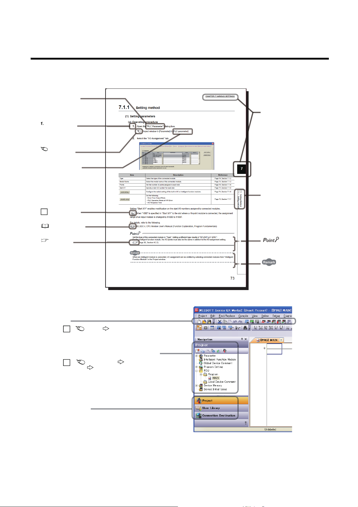
MANUAL PAGE ORGANIZATION
The section of
the current page is shown.
The chapter of
the current page is shown.
"" is used for
window names and items.
[ ] is used for items
in the menu bar and
the project window.
shows operating
procedures.
shows reference
manuals.
shows notes that
require attention.
shows mouse
operations.
*1
shows
reference pages.
shows setting or
operating examples.
Ex.
shows useful
information.
A window selected in the view selection area is displayed.
View selection area
[Online] [Write to PLC...]
Select [Online] on the menu bar,
and then select [Write to PLC...].
Project window
[Parameter]
[PLC Parameter]
Select [Project] from the view selection
area to open the Project window.
Menu bar
Ex.
Ex.
In the Project window, expand [Parameter] and
select [PLC Parameter].
In this manual, pages are organized and the symbols are used as shown below.
The following illustration is for explanation purpose only, and should not be referred to as an actual documentation.
*1 The mouse operation example is provided below.
11
Page 14

TERMS
Unless otherwise specified, this manual uses the following terms.
Ter m Description
A/D converter module A generic term for the main A/D converter module and extension A/D converter module
Buffer memory
CC-Link IE Field Network A high-speed and large-capacity open field network that is based on Ethernet (1000BASE-T)
Cyclic transmission
Data link A generic term for cyclic transmission and transient transmission
Dedicated instruction An instruction that simplifies programming for using functions of intelligent function modules
Disconnection A process of stopping data link if a data link error occurs
Extension A/D converter module
Extension analog module A generic term for the extension A/D converter module and extension D/A converter module
Extension D/A converter module
Extension I/O module A generic term for the extension input module and extension output module
Extension input module A generic term for extension modules where digital signals can be input
Extension module
Extension output module A generic term for extension modules where digital signals can be output
GX Works2
GX Works3
I/O module Another term for the CC-Link IE Field Network remote I/O module
Intelligent device station
Link device A device (RX, RY, RWr, or RWw) in a module on CC-Link IE Field Network
Link special register (SW) Word data that indicates the operating status and data link status of a module on CC-Link IE Field Network
Link special relay (SB) Bit data that indicates the operating status and data link status of a module on CC-Link IE Field Network
Local station
Main A/D converter module The abbreviation for the NZ2GF2BN-60AD4 CC-Link IE Field Network main analog-digital converter module
Main analog module A generic term for the main A/D converter module and main D/A converter module
Main D/A converter module The abbreviation for the NZ2GF2BN-60DA4 CC-Link IE Field Network main digital-analog converter module
Main module
Master station
Master/local module A generic term for the CC-Link IE Field Network master/local module
Network module
Relay station
REMFR The abbreviation for ZP.REMFR.
Remote buffer memory Buffer memory in a remote device station
Remote device station
Remote I/O station A station that exchanges I/O signals (bit data) with the master station by cyclic transmission
A memory in an intelligent function module, where data (such as setting values and monitoring values)
exchanged with a CPU module are stored
A function by which data are periodically exchanged among stations on the same network using link devices
(RX, RY, RWw, and RWr)
The abbreviation for the NZ2EX2B-60AD4 CC-Link IE Field Network extension analog-digital converter
module
The abbreviation for the NZ2EX2BN-60DA4 CC-Link IE Field Network extension digital-analog converter
module
A remote module with no CC-Link IE Field Network communication function. This module cannot be used as a
single module. However, connecting the module to the main module will increase the number of I/O points per
station.
The product name of the software package for the MELSEC programmable controllers
A station that exchanges I/O signals (bit data) and I/O data (word data) with another station by cyclic
transmission. This station responds to a transient transmission request from another station and also issues a
transient transmission request to another station.
A station that performs cyclic transmission and transient transmission with the master station and other local
stations. The station is controlled by programs in the CPU module or other equivalent modules on the station.
A module with the CC-Link IE Field Network communication function, which can be used as a single remote
module.
A station that controls the entire network. This station can perform cyclic transmission and transient
transmission with all stations. Only one master station can be used in a network.
A generic term for the following modules:
• CC-Link IE Field Network module
• CC-Link IE Controller Network module
• Ethernet interface module
• MELSECNET/H module
• MELSECNET/10 module
A station that includes two or more network modules. Data are passed through this station to stations on other
networks
A station that exchanges I/O signals (bit data) and I/O data (word data) with another station by cyclic
transmission. This station responds to a transient transmission request from another station.
12
Page 15

Ter m Description
Remote input (RX)
Remote output (RY)
Remote register (RWr)
Remote register (RWw)
REMTO The abbreviation for ZP.REMTO.
Reserved station A station reserved for future use. This station is not actually connected, but counted as a connected station
Return A process of restarting data link when a station recovers from an error
Simple motion module The abbreviation for the QD77GF CC-Link IE Field Network simple motion module
Slave station
Transient transmission
Bit data input from a slave station to the master station (For some areas in a local station, data are input in the
opposite direction.)
User's manual for the master/local module used
Bit data output from the master station to a slave station (For some areas in a local station, data are output in
the opposite direction.)
User's manual for the master/local module used
Word data input from a slave station to the master station (For some areas in a local station, data are input in
the opposite direction.)
User's manual for the master/local module used
Word data output from the master station to a slave station (For some areas in a local station, data are output
in the opposite direction.)
User's manual for the master/local module used
A generic term for stations other than a master station: local station, remote I/O station, remote device station,
and intelligent device station
A function of communication with another station, which is used when requested by a dedicated instruction or
GX Works2
13
Page 16
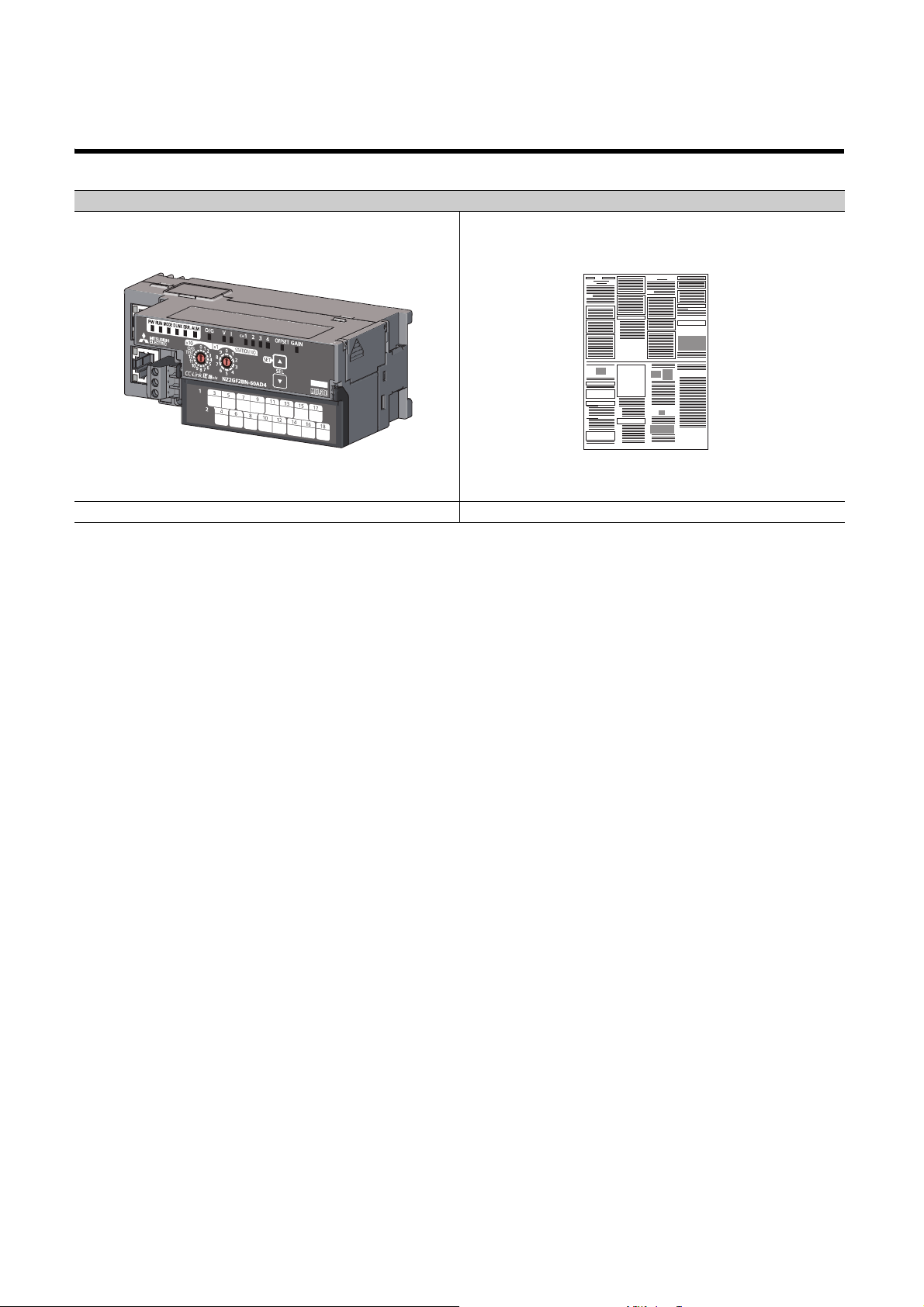
PACKING LIST
The following items are included in the package of this product. Before use, check that all the items are included.
A/D converter module
Module (The figure above shows the main A/D converter module.) Before Using the Product
14
Page 17
CHAPTER 1 A/D CONVERTER MODULE
Master station
CC-Link IE Field Network
Main A/D converter module
Control valve
Flow control
Tank
CHAPTER 1 A/D CONVERTER MODULE
This chapter describes the application and the features of the A/D converter module.
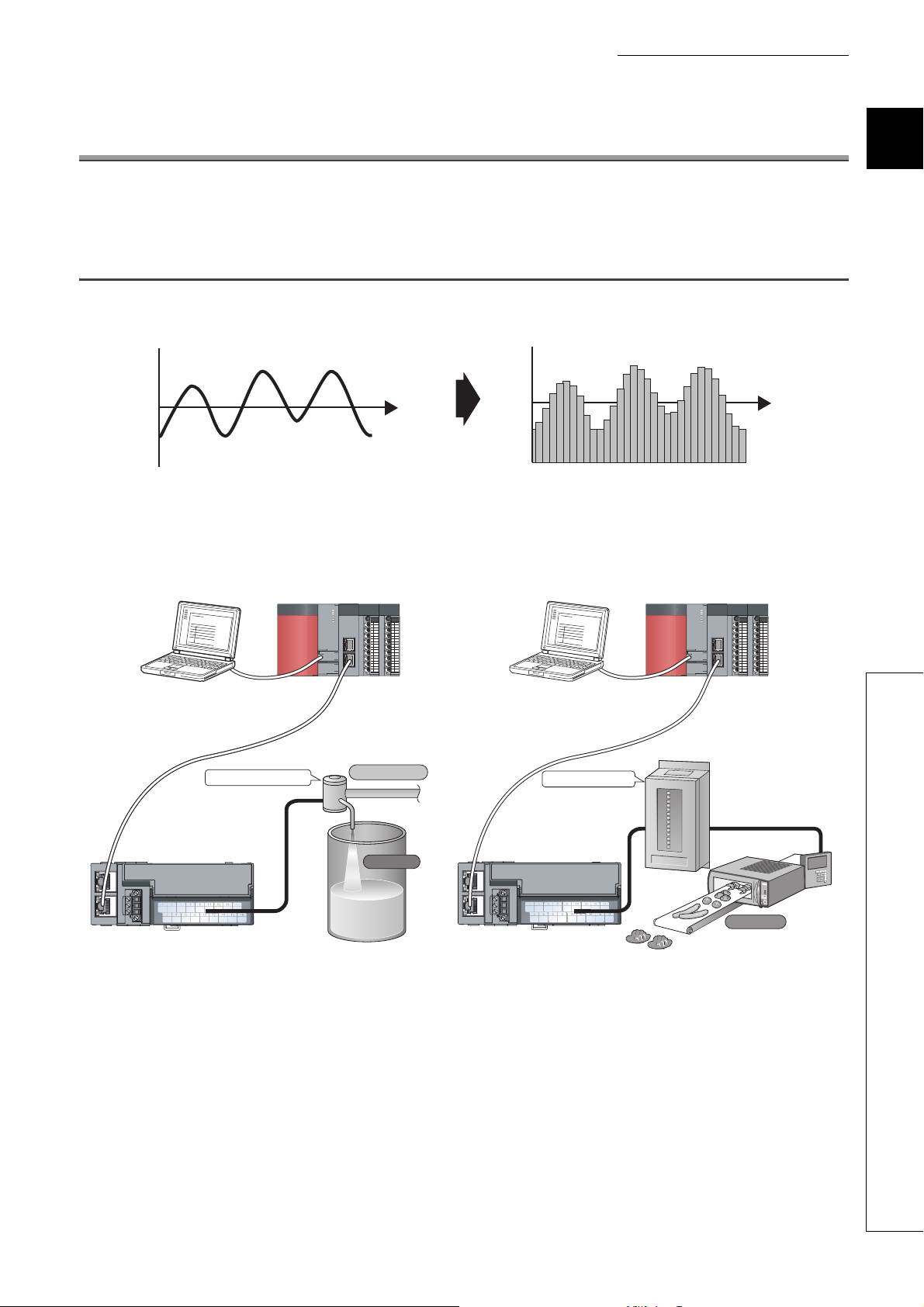
1.1 Application
The A/D converter module converts analog values that are input from external devices to digital operation values.
A/D conversion
Analog signal as a continuous amount
The converted digital operation value can be checked in the master station.
Using the A/D converter module allows the flow or temperature measured by the A/D converter module to be checked
through the master station.
Digital signal as a discrete sequence
1
Master station
1.1 Application
CC-Link IE Field Network
Power conditioner
Heater
Main A/D converter module
15
Page 18
1.2 Features
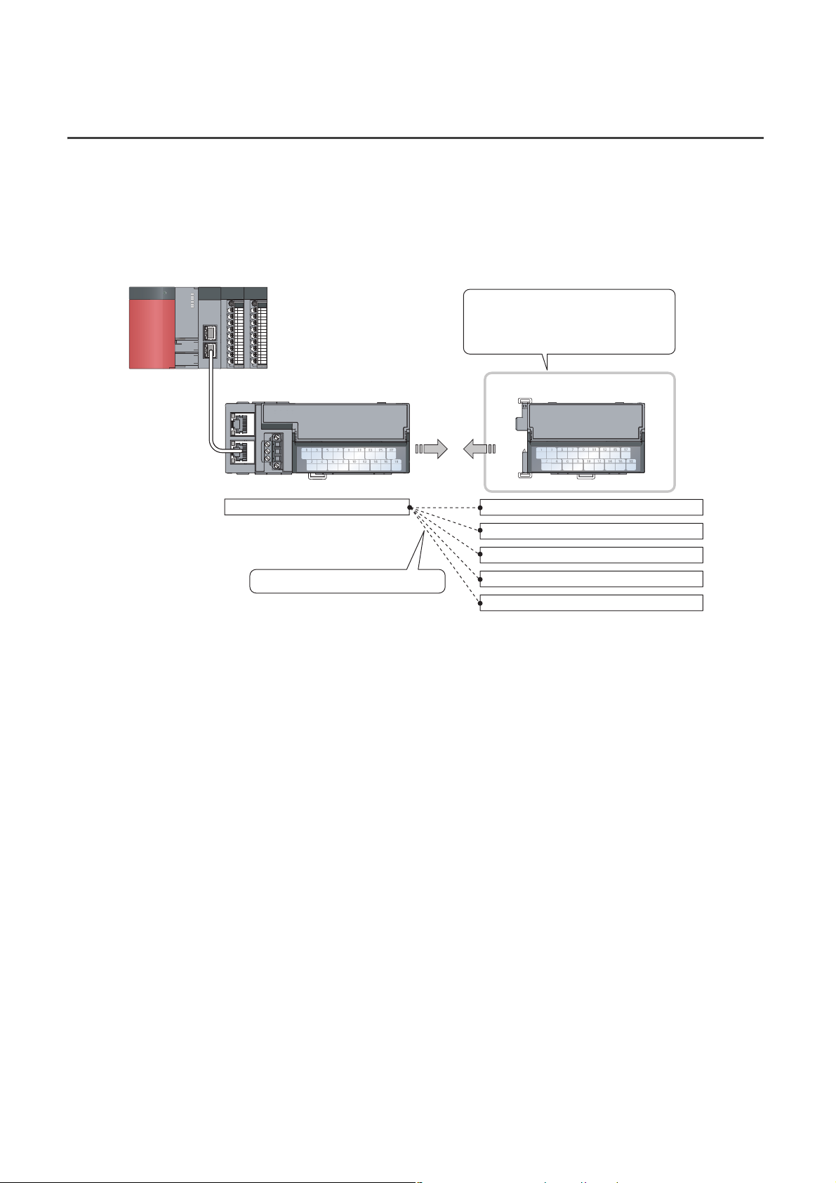
(1) Flexible system configuration
The employed connection block type provides the combined use of a main module and an extension module.
A flexible configuration can be achieved because various extension modules can be connected.
In addition, the main module always monitors the connection status of the extension module, leading to an early
detection of connection failure.
Various extension modules can be
connected according to the application.
No wiring of wires and Ethernet cables
is required.
Extension moduleMain module
Main A/D converter module
The flexible combination is possible.
Extension input module
Extension output module (sink type)
Extension output module (source type)
Extension A/D converter module
Extension D/A converter module
(2) Easy setting of station numbers
Station numbers are set with the rotary switch on the front of the module, where setting and checking the station
numbers are easy.
(3) Selectable conversion speed
A/D conversion at 100μs/channel meets the need of a high-speed conversion.
Under the environment in which noise is likely to occur, switching the conversion speed to 400μs/channel or
1ms/channel minimizes the effect of noise on the digital operation value, the stability of which is improved.
16
Page 19
CHAPTER 1 A/D CONVERTER MODULE
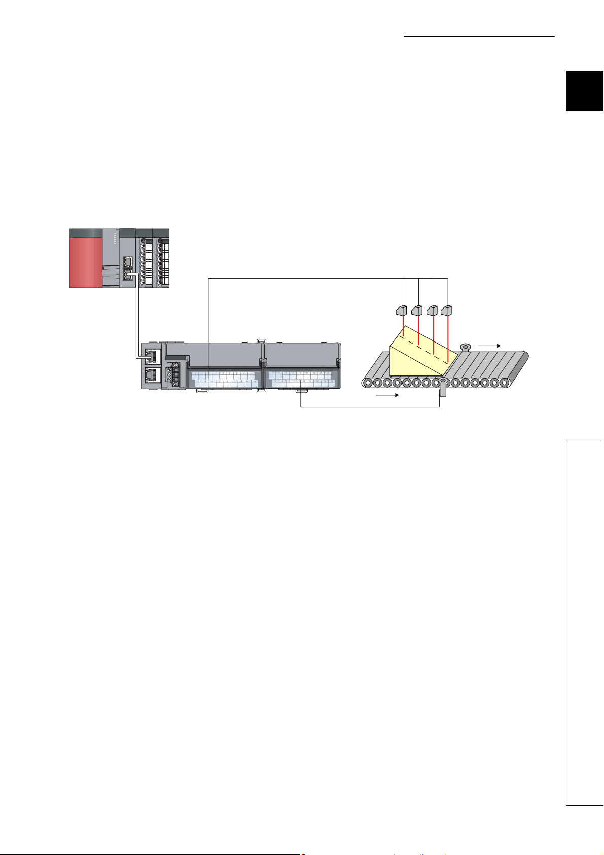
(4) A/D conversion at any desired timing
A/D conversion is performed once immediately after the input of a trigger conversion request to obtain the digital
operation value.
The combination with the external signal assignment function allows direct input of a trigger conversion request
from the extension input module, with the following advantages:
• Being free from the effect of the sequence scan and link scan, digital operation values can be constantly
obtained at a given timing, which leads to the improvement of the reliability.
• Digital operation values can be obtained without any program, which leads to a reduction in the cost of
creating a program.
Analog input signals (CH1 to CH4)
Displacement sensor
Extension input module
1
Main A/D converter module
Trigger conversion request by the external
signal assignment function
(5) Change to any scale
A/D conversion values can be converted to be within any scale, the range of which is determined arbitrarily.
According to the device that handles digital operation values, the scale can be changed without any program,
resulting in cost reduction.
(6) Detection of the disconnection
An input range of 1 to 5V, or 4 to 20mA allows the detection of the disconnection of analog input, facilitating the
diagnosis of the cause at the time of a trouble.
In combination with the external signal assignment function, the extension output module allows a signal (input
signal error detection signal) to be output to the outside without any program upon detection of the disconnection.
At this time, there is no influence of the sequence scan and link scan.
1.2 Features
17
Page 20
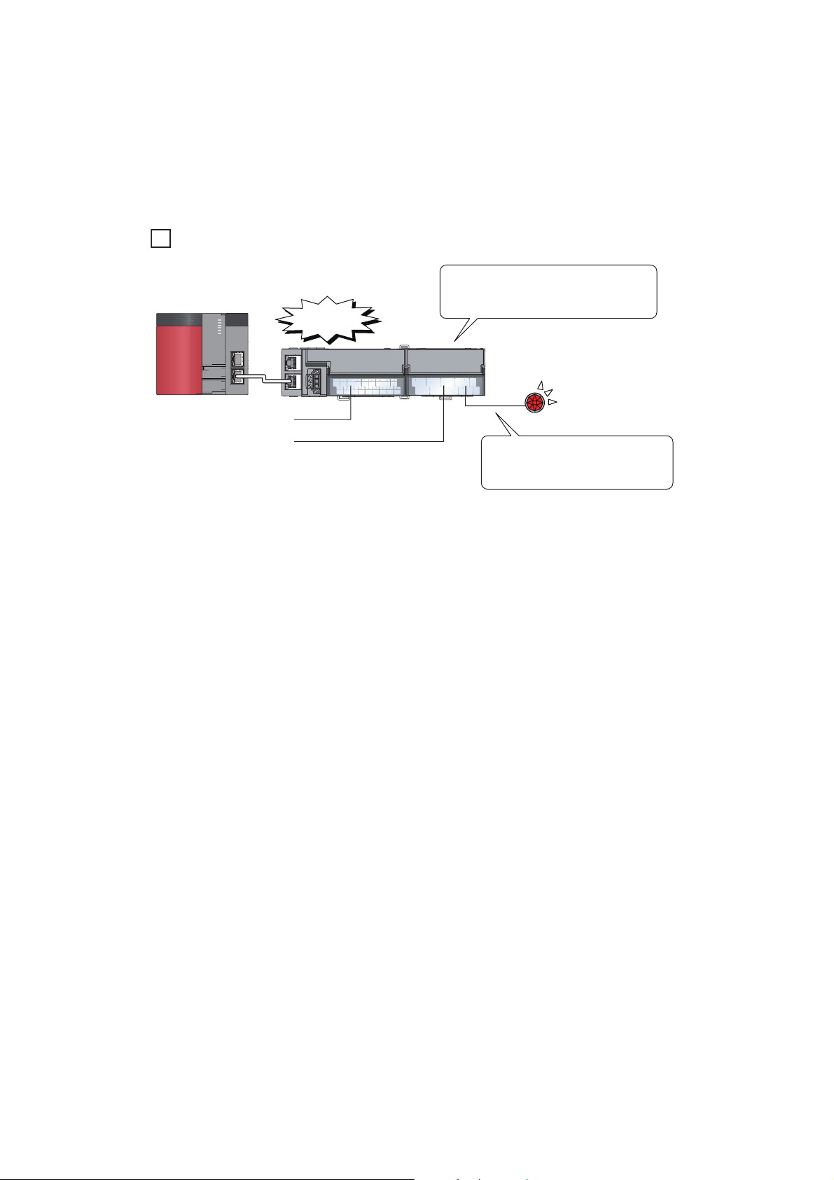
(7) Input and output without an influence of the sequence scan and link scan
Ex.
Main A/D converter module
Extension output module
An error has
occurred.
An error signal occurred in the A/D
converter module can be output to the
extension output module directly.
Error lamp
(external device)
Programming is not necessary to
turn on an error lamp when an error
occurs.
Using the external signal assignment function allows a trigger conversion request to be input from the extension
input module. In the event of an error or an alert, an error status or an alert status can be output from the
extension output module.
These input and output are not affected by the sequence scan and link scan.
To turn on the lamp when an error occurs.
(8) Support for the CC-Link IE Field Network synchronous communication
function
A/D conversion can be performed together with the synchronization period of the master station that supports the
CC-Link IE Field Network synchronous communication function.
This enables the A/D converter module to operate at the same timing of other slave stations sharing the same
network.
18
Page 21
CHAPTER 1 A/D CONVERTER MODULE
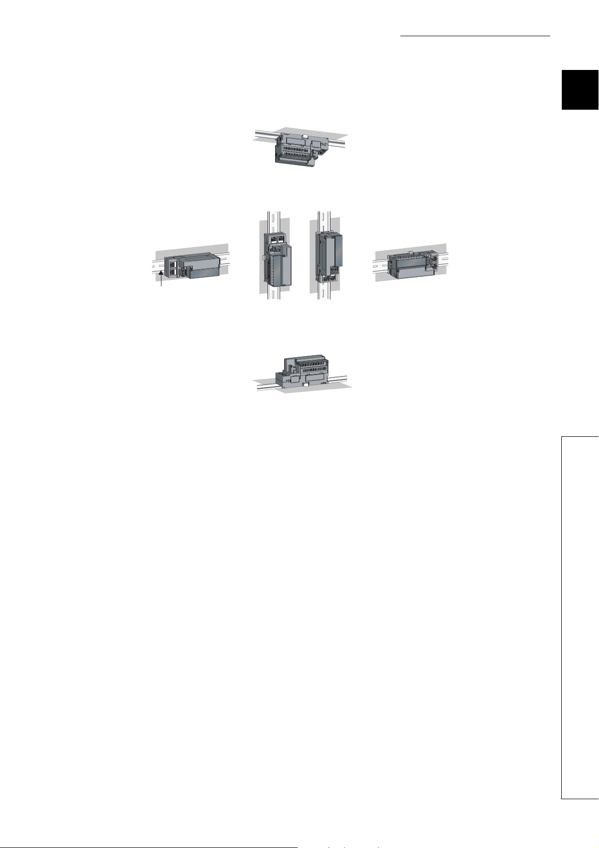
Downward installation
DIN rail
Vertical installation Horizontal installation Horizontal installation
(upside down)
Upward installation
(9) Various installation methods
The module can be installed in six directions using a DIN rail.
1
(10)Easy module replacement
The terminal block for module power supply and FG, and the terminal block for analog input signals have a two-
piece structure, where the module can be replaced with the wire connected. In addition, the terminal block for
analog input signals has a lift-up structure, where the terminal block lifts only by loosening the terminal block
mounting screw, enabling it to be removed easily.
(11)Check on the error history
The history of the last 15 errors and occurrence time is stored in the main A/D converter module.
Checking the error information of the past helps to identify the cause at the time of a trouble.
(12)Easy settings by CC IE Field configuration of the engineering tool
The CC IE Field configuration of the engineering tool makes it possible to set parameters on its window, thereby
reducing the programs. In addition, the setting status and the operating status of modules can be checked easily.
1.2 Features
19
Page 22
CHAPTER 2 PART NAMES
*1
*1
3)
2)
4) 5) 6)
1)
8)
7)
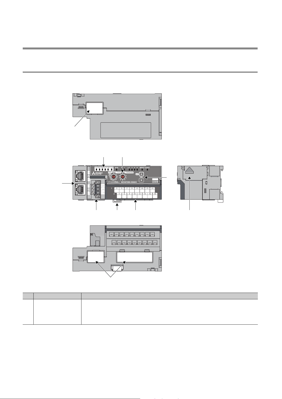
2.1 Main A/D Converter Module
This section describes part names of the main A/D converter module.
*1 Do not remove this seal because it is used for our maintenance purposes.
No. Name Application
1) Station number setting switch
A rotary switch for the following setting and test.
• Station Number Setting ( Page 50, Section 6.1)
• Offset/Gain Setting ( Page 83, Section 7.3)
• Unit Test ( Page 185, Section 11.5)
When operating the station number setting switch, use a slotted screwdriver with 3.5mm or less width of the tip.
20
Page 23

No. Name Application
PW LED (green)
RUN LED (green)
MODE LED (green)
D LINK LED (green)
ERR. LED (red)
2)
ALM LED (red)
O/G LED (green)
V LED (green),
I LED (green)
CH1 to CH4 LED
(green)
OFFSET LED (green),
GAIN LED (green)
P1
L ER LED (red)
LINK LED (green)
3)
P2
L ER LED (red)
LINK LED (green)
Terminal block for module
4)
power supply and FG
5) DIN rail hook A hook for mounting a module on a DIN rail
Terminal cover Covers for preventing electric shock while the power is on
6)
Terminal block for analog
input signals
7) SET/SEL button In offset/gain setting mode, select the set target by pressing button or button.
8) Extension connector cover
Indicates the power supply status of the main A/D converter module.
• On: Power-on
• Off: Power-off
Indicates the operating status of the main A/D converter module.
• On: Operating normally; Writing data to the non-volatile memory (while in offset/gain setting mode)
• Off: Major error occurred
Indicates the mode of the main A/D converter module.
• On: In online mode
• Flashing: In unit test mode
• Off: In offset/gain setting mode
Indicates the data link status of the main A/D converter module.
• On: Data link in operation (cyclic transmission in progress)
• Flashing: Data link in operation (cyclic transmission stopped)
• Off: Data link not performed (disconnected)
Indicates the error status of the main A/D converter module and the extension module.
• On: Moderate error or major error occurred
• Flashing: Warning occurred
• Off: In normal operation
Indicates the alert status of the main A/D converter module and the extension module.
• On: Alert issued
• Flashing: Input signal error detected
• Off: In normal operation
Indicates the module is in offset/gain setting mode.
• On: In offset/gain setting mode
• Off: In a mode other than offset/gain setting mode
Indicates the user range of a set target selected in offset/gain setting mode.
Set target V LED I LED
User range setting 1 (-10 to 10V) On Off
User range setting 2 (-5 to 5V, -20 to 20mA) Off On
Indicates the channel of a set target selected in offset/gain setting mode.
• On: The channel corresponding to the number being on is the set target.
• Off: The channel corresponding to the number being off is not the set target.
Indicates whether the selected setting is offset or gain in the offset/gain setting mode.
Set target OFFSET LED GAIN LED
Offset On Off
Gain Off On
PORT1 connector for the connection to CC-Link IE Field Network (RJ45 connector)
Connect an Ethernet cable. ( Page 60, Section 6.5)
There are no restrictions on the connection order of the cables for the P1 connector and P2 connector.
• On: Module received abnormal data, or module performing loopback
• Off: Module received normal data, or module not performing loopback
• On: Link-up
• Off: Link-down
PORT2 connector for the connection to CC-Link IE Field Network (RJ45 connector)
Connect an Ethernet cable. ( Page 60, Section 6.5)
There are no restrictions on the connection order of the cables for the P1 connector and P2 connector.
(same as the LEDs of the P1 connector)
A terminal block for the connection of a module power supply (24VDC) and FG
A two-piece screw terminal block for the connection to an external device
A cover to protect a connector of an extension module. Do not remove the cover if an extension module is not
connected to the connector.
CHAPTER 2 PART NAMES
2
2.1 Main A/D Converter Module
21
Page 24

(1) Module status and LED status
The following table shows how module status and LED status correspond each other.
LED status
Module status Data link status
Disconnecting Disconnection On On On Off Off Off Off
Data link in operation Data link in operation On On On On Off Off Off
Normal mode
Offset/gain setting mode On Off Off Flashing Off
Unit test
Communication error Cyclic stop On On On Flashing Off Off Off
Error
Warning Minor error On On
Alarm
Reserved station
specification in
progress
Link stop Cyclic stop On On On Flashing Off Off Off
In progress On On Flashing
Completed
successfully
Completed with an
error
Major error On Off
Moderate error On On
Alert issued On On On
Input signal error
occurred
Cyclic stop On On On Flashing Off Off Off
On On Off Off Off Off Off
On On Off Off On Off Off
On On On
PW LED RUN LED
MODE
LED
*2 *1
*2 *1
*2 *1
D LINK
LED
*1
*1 *1
*1 *1
ERR. LED ALM LED O/G LED
*1
Off Off Off
*3 *1
On
On
Flashing
*1
*1
On Off
Flashing Off
On
Off
Off
Off
*1 Either On, Flashing, or Off.
*2 Either On or Off.
*3 A failure of the module may not allow the LED to turn on.
22
Page 25
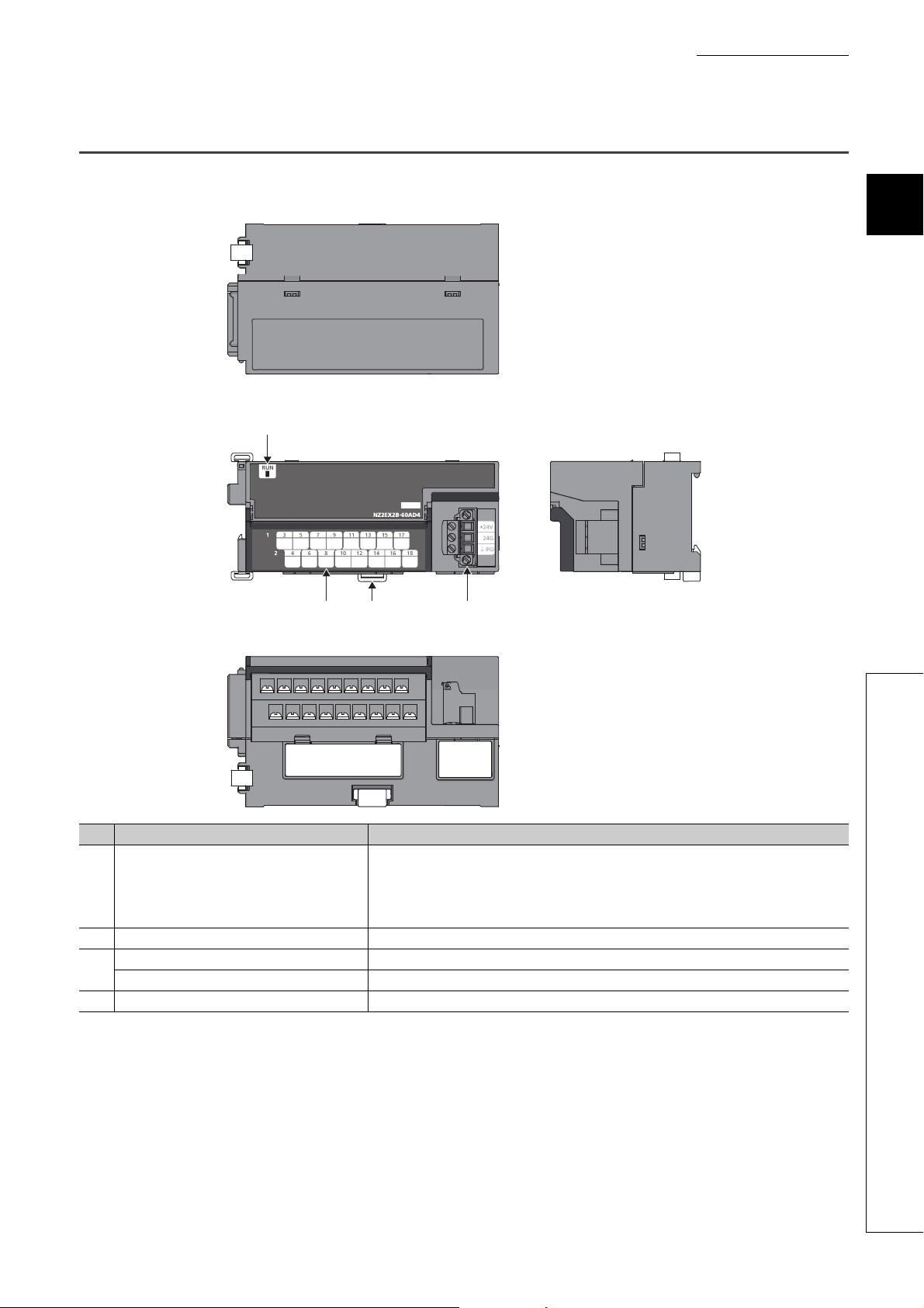
2.2 Extension A/D Converter Module
This section describes part names of the extension A/D converter module.
1)
CHAPTER 2 PART NAMES
2
3) 2) 4)
No. Name Application
Indicates the operating status of the extension A/D converter module.
• On: In normal operation
1) RUN LED (green)
2) DIN rail hook A hook for mounting a module on a DIN rail
Terminal cover Covers for preventing electric shock while the power is on
3)
Terminal block for analog input signals A two-piece terminal block for the connection to an external device
4) Terminal block for external power supply and FG A terminal block for the connection of an external power supply (24VDC) and FG
• Flashing: External power supply being off
• Off: Major error occurred; main analog module being in offset/gain setting mode; or main analog
module being in unit test mode
2.2 Extension A/D Converter Module
23
Page 26
CHAPTER 3 SPECIFICATIONS
This chapter describes the specifications of the A/D converter module.
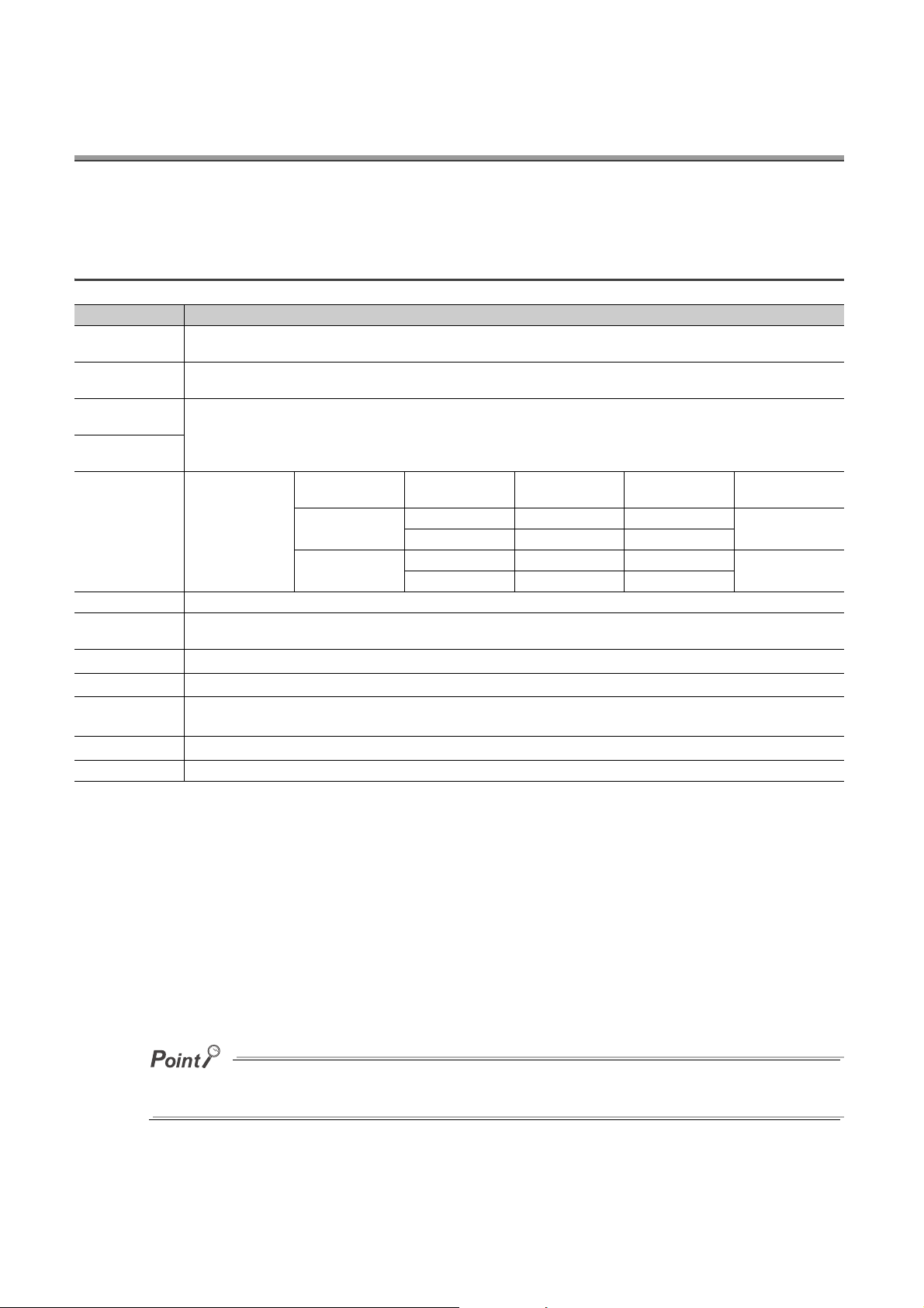
3.1 General Specifications
Item Specifications
Operating ambient
temperature
Storage ambient
temperature
Operating ambient
humidity
Storage ambient
humidity
Vibration resistance
Shock resistance Compliant with JIS B 3502 and IEC 61131-2 (147m/, 3 times each in X, Y, and Z directions)
Operating
atmosphere
Operating altitude
Installation location
Overvoltage
*3
category
Pollution degree
Equipment class Class
0 to 55
-25 to 75
5 to 95%RH, non-condensing
Compliant with JIS
B 3502 and IEC
61131-2
No corrosive gases
*1
0 to 2000m
Inside a control panel
or less
*4
2 or less
Under intermittent
vibration
Under continuous
vibration
*2
Frequency
5 to 8.4Hz 3.5mm
8.4 to 150Hz 9.8m/
5 to 8.4Hz 1.75mm
8.4 to 150Hz 4.9m/
Constant
acceleration
Half amplitude Number of sweeps
10 times each in X,
Y, and Z directions
*1 Do not use or store the A/D converter module under pressure higher than the atmospheric pressure at an altitude of 0
meters. Doing so may cause malfunction. When using the A/D converter module under pressure, please consult your
local Mitsubishi representative.
*2 If the environment satisfies the operating ambient temperature, operating ambient humidity and other conditions, the
module can be used even outside the control panel.
*3 This indicates the assumption that the equipment is connected to which type of power distribution system, from the
public electrical power distribution network down to machinery within premises.
Category applies to equipment for which electrical power is supplied from fixed facilities. The surge voltage withstand
level for the equipment with up to the rated voltage of 300V is 2500V.
*4 This index indicates the degree to which conductive material is generated in terms of the environment in which the
equipment is used.
In pollution degree 2, only non-conductive pollution occurs. A temporary conductivity caused by condensation must be
expected occasionally.
For compliance with the EMC Directive, refer to "EMC and Low Voltage Directives" in this manual. ( Page 234, Appendix
7)
24
Page 27

CHAPTER 3 SPECIFICATIONS
3.2 Performance Specifications
3.2.1 Main A/D converter module
Item Description
Station type Remote device station
Number of analog input points 4 points (4 channels)/module
Analog input
Digital output 16-bit signed binary (-16384 to 16383)
I/O characteristics, maximum
resolution
Conversion
accuracy
Conversion speed
Absolute maximum input
Isolation method
Withstand voltage
Noise immunity Noise voltage 500Vp-p, noise width 1μs, noise frequency 25 to 60Hz (noise simulator condition)
External interface
Applicable DIN rail TH35-7.5Fe, TH35-7.5Al (compliant with IEC 60715)
Applicable wire
size
*1
*2
Voltage -10 to 10VDC (input resistance 1MΩ)
Current 0 to 20mADC (input resistance 250Ω)
Input Input range Digital output value Maximum resolution
-10 to 10V
User range setting 1 (-10 to 10V) 0.5mV
Volt age
Current
Ambient
temperature
(25±5)
Ambient
temperature
(0 to 55)
*5
Communication
part
Module power
supply part
I/O part
For power supply Core: 0.5 to 1.5 (20 to 16 AWG)
For I/O Core: 0.3 to 2.0 (22 to 14 AWG)
±0.1%
±0.2%
100μs/channel
400μs/channel
1ms/channel
Voltage: ±15V, Current: ±30mA
Between communication system terminal and all analog input terminals: Photocoupler isolation
Between power supply system terminal and all analog input terminals: Transformer isolation
Between input channels: Non-isolation
Between all power supply and communication system terminals and all analog input terminals
500VAC for 1 minute
RJ45 connector
Terminal block for module power supply and FG
Tightening torque range for terminal screw (M2.5 screw): 0.5 to 0.6N⋅m
18-point two-piece terminal block (M3 screw)
Tightening torque range for terminal screw (M3 screw × 5.2): 0.43 to 0.57N⋅m
User range setting 2 (-5 to 5V) 0.25mV
0 to 5V
1 to 5V 0.25mV
0 to 20mA
4 to 20mA 1μA
User range setting 2 (-20 to 20mA) -16000 to 16000 1μA
-16000 to 16000
0 to 16000
0 to 16000
*3
3
0.625mV
0.3125mV
1.25μA
3.2 Performance Specifications
25
Page 28

Item Description
TE 0.5-10 (NICHIFU Co., Ltd.) [Applicable wire size: 0.5]
TE 0.75-10 (NICHIFU Co., Ltd.) [Applicable wire size: 0.75]
Terminal block for
module power
Applicable
solderless
terminal
Cyclic
transmission
Communication cable
Applicability of extension module Connectable (Max. one module)
External power supply
Weight 0.30kg
supply and FG
Terminal block for
analog input
signals
RX/RY points 32 points + 16 points × Number of extension modules
RWr/RWw points 16 points + Points of each extension module
TE 1.0-10 (NICHIFU Co., Ltd.) [Applicable wire size: 0.9 to 1.0]
TE 1.5-10 (NICHIFU Co., Ltd.) [Applicable wire size: 1.25 to 1.5]
AI 0.5-10WH (Phoenix Contact Co., Ltd.) [Applicable wire size: 0.5]
*4
AI 0.75-10GY (Phoenix Contact Co., Ltd.) [Applicable wire size: 0.75]
AI 1-10RD (Phoenix Contact Co., Ltd.) [Applicable wire size: 1.0]
AI 1.5-10BK (Phoenix Contact Co., Ltd.) [Applicable wire size: 1.5]
RAV1.25-3 (compliant with JIS C 2805) [Applicable wire size: 0.3 to 1.25]
V2-MS3 (JST Mfg. Co., Ltd) [Applicable wire size: 1.25 to 2.0]
RAP2-3SL (Nippon Tanshi Co., Ltd.) [Applicable wire size: 1.25 to 2.0]
TGV2-3N (NICHIFU Co., Ltd.) [Applicable wire size: 1.25 to 2.0]
An Ethernet cable that meets the 1000BASE-T standard:
Category 5e or higher (double shielded, STP), straight cable
24VDC (20.4 to 28.8VDC)
Inrush current: 36.5A, 1ms or lower
Current consumption: 210mA
*1 For details on the I/O conversion characteristics, refer to the following:
• I/O Conversion Characteristics of A/D Conversion ( Page 229, Appendix 4)
*2 Except for the conditions under noise influence.
*3 This current value is an instantaneous value at which no breakdown occurs in the internal resistance of the module. The
maximum input current value for constant application is 24mA.
*4 Do not connect two or more cables to the terminal.
*5 The sampling period varies depending on whether an extension analog module is connected or not. For details, refer to
the following:
• Conversion Speed and Sampling Period ( Page 90, Section 8.5.1)
26
Page 29

CHAPTER 3 SPECIFICATIONS
3.2.2 Extension A/D converter module
Item Description
Number of analog input points 4 points (4 channels)/module
Analog input
Digital output 16-bit signed binary (-16384 to 16383)
I/O characteristics, maximum resolution
Conversion
*2
accuracy
Conversion speed
Absolute maximum input
Isolation method
Withstand voltage
Noise immunity Noise voltage 500Vp-p, noise width 1μs, noise frequency 25 to 60Hz (noise simulator condition)
External interface
Applicable DIN rail TH35-7.5Fe, TH35-7.5Al (compliant with IEC 60715)
Applicable wire size
Applicable
solderless terminal
Cyclic transmission
Module power
supply (supplied
from a main module)
External power supply
Weight 0.22kg
Voltage -10 to 10VDC (input resistance 1MΩ)
Current 0 to 20mADC (input resistance 250Ω)
Input Input range Digital output value Maximum resolution
-10 to 10V -16000 to 16000 0.625mV
Volt age
*1
Current
Ambient
temperature
(25±5)
Ambient
temperature
(0 to 55)
*5
External power
supply part
I/O part
For power supply Core: 0.5 to 1.5 (20 to 16 AWG)
For I/O Core: 0.3 to 2.0 (22 to 14 AWG)
Terminal block for
external power
supply and FG
Terminal block for
analog input
signals
RX/RY points 16 points
RWr/RWw points 16 points
Voltage 24VDC (20.4 to 28.8VDC)
Current 90mA
±0.1%
±0.2%
100μs/channel
400μs/channel
1ms/channel
Voltage: ±15V, Current: ±30mA
Between communication system terminal and all analog input terminals: Photocoupler isolation
Between power supply system terminal and all analog input terminals: Transformer isolation
Between input channels: Non-isolation
Between all power supply and communication system terminals and all analog input terminals
500VDC for 1 minute
Terminal block for external power supply and FG
Tightening torque range for terminal screw (M2.5 screw): 0.5 to 0.6N⋅m
18-point two-piece terminal block (M3 screw)
Tightening torque range for terminal screw (M3 screw × 5.2): 0.43 to 0.57N⋅m
TE 0.5-10 (NICHIFU Co., Ltd.) [Applicable wire size: 0.5]
TE 0.75-10 (NICHIFU Co., Ltd.) [Applicable wire size: 0.75]
TE 1.0-10 (NICHIFU Co., Ltd.) [Applicable wire size: 0.9 to 1.0]
TE 1.5-10 (NICHIFU Co., Ltd.) [Applicable wire size: 1.25 to 1.5]
AI 0.5-10WH (Phoenix Contact Co., Ltd.) [Applicable wire size: 0.5]
*4
AI 0.75-10GY (Phoenix Contact Co., Ltd.) [Applicable wire size: 0.75]
AI 1-10RD (Phoenix Contact Co., Ltd.) [Applicable wire size: 1.0]
AI 1.5-10BK (Phoenix Contact Co., Ltd.) [Applicable wire size: 1.5]
RAV1.25-3 (compliant with JIS C 2805) [Applicable wire size: 0.3 to 1.25]
V2-MS3 (JST Mfg. Co., Ltd) [Applicable wire size: 1.25 to 2.0]
RAP2-3SL (Nippon Tanshi Co., Ltd.) [Applicable wire size: 1.25 to 2.0]
TGV2-3N (NICHIFU Co., Ltd.) [Applicable wire size: 1.25 to 2.0]
24VDC (20.4 to 28.8VDC)
Inrush current: 22.0A, 1ms or lower
Current consumption: 45mA
0 to 5V
1 to 5V 0.25mV
0 to 20mA
4 to 20mA 1μA
0 to 16000
0 to 16000
*3
3
0.3125mV
1.25μA
3.2 Performance Specifications
27
Page 30

*1 For details on the I/O conversion characteristics, refer to the following:
• I/O Conversion Characteristics of A/D Conversion ( Page 229, Appendix 4)
*2 Except for the conditions under noise influence.
*3 This current value is an instantaneous value at which no breakdown occurs in the internal resistance of the module. The
maximum input current value for constant application is 24mA.
*4 Do not connect two or more wires to the terminal.
*5 The module operates at the conversion speed of a main analog module. For details, refer to the following:
• Conversion Speed and Sampling Period ( Page 90, Section 8.5.1)
28
Page 31

CHAPTER 3 SPECIFICATIONS
Main A/D converter module Extension module
NZ2GF2BN-60AD4
Module power supply current:
210mA
NZ2EX2B1-16T
Module power supply current:
30mA
240mA
(Total current consumption)
+=
3.3 How to Calculate Current Consumption
The total current consumption of the modules is calculated by summing the module power supply current in the main
A/D converter module and extension module.
For the value of the module power supply current, refer to the specifications of each module.
• Performance specifications of main A/D converter module ( Page 25, Section 3.2.1)
• Performance specifications of extension A/D converter module ( Page 27, Section 3.2.2)
• Performance specifications of extension I/O module ( CC-Link IE Field Network Remote I/O Module
User's Manual)
• Performance specifications of extension D/A converter module ( CC-Link IE Field Network Digital-Analog
Converter Module User's Manual)
The value of the module power supply current in the extension module described in the specifications is the value of
the module power supply current supplied from the main A/D converter module.
3
3.3 How to Calculate Current Consumption
29
Page 32

3.4 Function List
: Available, : Not available
Item Description
Allows A/D conversion to be enabled or disabled for
A/D conversion enable/disable function
Conversion speed switch function
Sampling processing
Time
average
A/D
conversion
method
Range switching function
Offset/gain setting function Allows the correction of errors in digital output values. Page 83, Section 7.3
Maximum value/minimum value hold
function
Input signal error detection function Detects a disconnection of analog input signals. Page 101, Section 8.9
Alert output function (process alarm)
Scaling function
Shift function
Digital clipping function
Averaging
processing
Count
average
Moving
average
each channel.
Disabling the A/D conversion for unused channels
reduces the conversion cycles.
Allows the selection of the conversion speeds to be
either 100μs, 400μs or 1ms.
Performs A/D conversion on analog input values
sequentially, storing the digital operation values into
the remote register.
Performs A/D conversion for a set period of time and
averages the total value excluding the maximum and
the minimum values, storing the averaged value into
the remote register. The number of processing times
within the set period of time varies depending on the
number of channels used (number of channels where
A/D conversion is enabled).
Performs A/D conversion a set number of times and
averages the total value excluding the maximum and
the minimum values, storing the averaged value into
the remote register. Time taken to store the average
value by count average varies depending on the
number of channels used (the number of channels
where A/D conversion is enabled).
Takes in digital operation values a set number of times
at every sampling period and averages these values,
storing the averaged value into the remote register.
The target range for average processing moves at
each sampling, thereby allowing the latest digital
operation value to be obtained.
Allows the input range to be selected for each channel
from the following:
• Factory default range (4 to 20mA, 0 to 20mA, 1 to
5V, 0 to 5V, -10 to 10V)
• User range (user range setting 1, user range setting
2)
For each channel, stores the maximum and minimum
values of digital operation values into the remote
buffer memory.
Outputs an alert when a digital operation value falls
within the alert output range set in advance.
Performs scale conversion on a digital operation value
within the range of the scaling upper limit value and
the scaling lower limit value, both of which are set at
desired values.
Adds the conversion value shift amount specified to a
digital operation value and stores it into the remote
register. This function facilitates fine adjustment at the
system start-up.
Allows the maximum value and the minimum value of
a digital output value to be fixed at 16000 and 0 or 16000 respectively if a voltage or current exceeding
the input range is input.
Available or not
*1
Main
Page 89, Section 8.4
Page 89, Section 8.5
Page 100, Section 8.8
Page 105, Section 8.10
Page 108, Section 8.11
Page 113, Section 8.12
Page 117, Section 8.13
Extension
*1
*2
Reference
Page 95, Section 8.6 (1)
Page 95, Section 8.6 (2)
(a)
Page 96, Section 8.6 (2)
(b)
Page 97, Section 8.6 (2)
(c)
Page 99, Section 8.7
30
Page 33

CHAPTER 3 SPECIFICATIONS
Item Description
Difference conversion function
Trigger conversion function
CC-Link IE Field Network synchronous
communication function
Error notification function
Functions with an extension I/O module
connected
Functions with an extension analog
module connected
CC-Link IE Field Network diagnostic
function
*1 "Main" and "Extension" indicate the following modules, respectively:
Main: Main A/D converter module
Extension: Extension A/D converter module
*2 The extension A/D converter module does not support user range.
Subtracts the difference conversion reference value
from a digital operation value and stores the obtained
value into the remote register.
Provides A/D conversion in accordance with the input
of Trigger conversion request.
Trigger conversion request that is input to the
extension input module via an external device also
allows A/D conversion.
Performs A/D conversion with a synchronization
period of the master station that supports the CC-Link
IE Field Network synchronous communication
function. This makes it possible to synchronize the
operation with other slave stations sharing the same
network.
Notifies an error to the master station by the remote
input signal if a moderate error or a major error occurs
in the A/D converter module.
The main A/D converter module permits the
connection of one extension I/O module.
• With an extension input module connected, remote
output signals of the main A/D converter module can
be assigned to remote input signals of the extension
input module connected.
• With an extension output module connected, remote
input signals of the main A/D converter module can
be assigned to remote output signals of the
extension output module connected.
Functions unique to an extension I/O module can also
be used.
The main A/D converter module permits the
connection of one extension A/D converter module.
With the extension A/D converter module connected,
A/D conversion processing of up to eight channels is
possible.
The main A/D converter module permits the
connection of one extension D/A converter module.
With the extension D/A converter module connected,
A/D conversion processing of four channels and D/A
conversion processing of four channels is possible.
Allows the presence or absence of a network error to
be checked by accessing the engineering tool
connected to the CPU module.
Available or not
*1
Main
Page 122, Section 8.14
Page 135, Section 8.16
Page 142, Section 8.17
Page 145, Section 8.18.1
Page 150, Section 8.18.2
Page 151, Section 8.18.3
Page 152, Section 8.19
Extension
*1
Reference
Page 127, Section 8.15
3
3.4 Function List
31
Page 34
3.5 List of Remote I/O Signals
This section lists I/O signals for a master/local module.
The I/O signal assignment shown assumes that the remote I/O signals of the main module are assigned to RX0 to
RX1F and RY0 to RY1F.
Remote input (RX) indicates the input signal from A/D converter module to master/local module.
Remote output (RY) indicates the output signal from master/local module to A/D converter module.
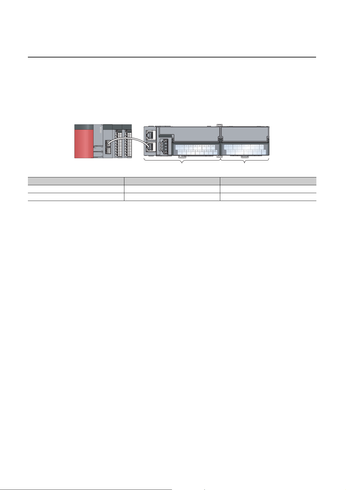
The remote I/O signals of the main A/D converter module and extension module are assigned as shown below.
Main A/D converter module Extension module
Module Remote input (RX) Remote output (RY)
Main A/D converter module RX0 to RX1F RY0 to RY1F
Extension module RX20 to RX2F RY20 to RY2F
For details on the remote I/O signals, refer to the following:
• Page 189, Appendix 1
32
Page 35
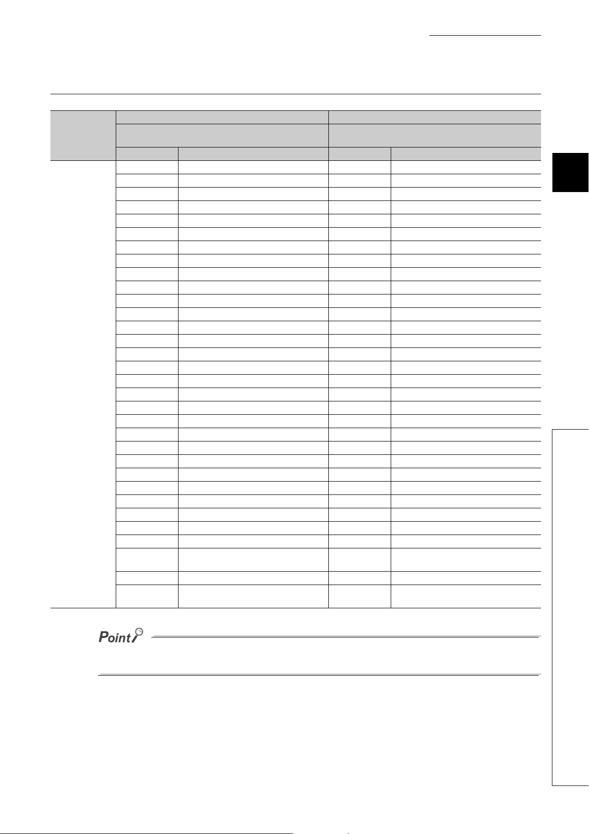
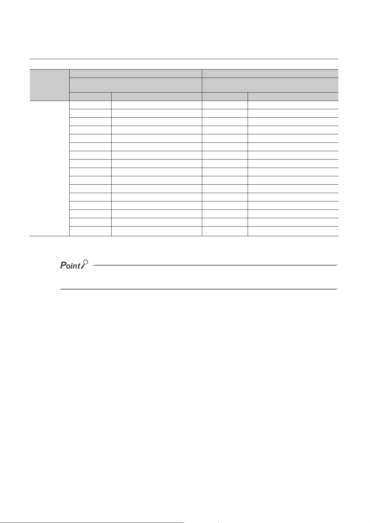
3.5.1 Main A/D converter module
Remote input Remote output
Module type
Main A/D
converter module
Signal direction: Main A/D converter module→Master/local
module
Device No. Description Device No. Description
RX0 Use prohibited RY0 Use prohibited
RX1 Use prohibited RY1 Use prohibited
RX2 Use prohibited RY2 Use prohibited
RX3 Use prohibited RY3 Use prohibited
RX4 Use prohibited RY4 Use prohibited
RX5 Use prohibited RY5 Use prohibited
RX6 Use prohibited RY6 Use prohibited
RX7 Warning flag RY7 Use prohibited
RX8 Use prohibited RY8 Use prohibited
RX9 Initial data setting completion flag RY9 Initial data setting request flag
RXA Error flag RYA Error clear request flag
RXB Remote READY RYB Use prohibited
RXC Use prohibited RYC Use prohibited
RXD Use prohibited RYD Use prohibited
RXE Use prohibited RYE Use prohibited
RXF Use prohibited RYF Use prohibited
RX10 CH1 A/D conversion completed flag RY10 Use prohibited
RX11 CH2 A/D conversion completed flag RY11 Use prohibited
RX12 CH3 A/D conversion completed flag RY12 Use prohibited
RX13 CH4 A/D conversion completed flag RY13 Use prohibited
RX14 CH1 Difference conversion state flag RY14 CH1 Difference conversion trigger
RX15 CH2 Difference conversion state flag RY15 CH2 Difference conversion trigger
RX16 CH3 Difference conversion state flag RY16 CH3 Difference conversion trigger
RX17 CH4 Difference conversion state flag RY17 CH4 Difference conversion trigger
RX18 Alert output signal RY18 Use prohibited
RX19 Trigger conversion completed flag RY19 Trigger conversion request
RX1A Use prohibited RY1A Trigger conversion completed clear request
RX1B Use prohibited RY1B Use prohibited
RX1C Input signal error detection signal RY1C Use prohibited
RX1D
RX1E Use prohibited RY1E Use prohibited
RX1F
Maximum value/minimum value reset
completed flag
External power supply monitor status flag (for
extension output module)
CHAPTER 3 SPECIFICATIONS
Signal direction: Master/local module→Main A/D converter
module
RY1D Maximum value/minimum value reset request
RY1F
External power supply monitor request flag
(for extension output module)
3
3.5 List of Remote I/O Signals
Do not use any "Use prohibited" remote I/O signals. If any of the signals are used, correct operation of the module cannot be
guaranteed.
33
Page 36
(1) Remote I/O signals of extension modules
The remote I/O signals differ depending on the model of extension module.
• For the extension A/D converter module, refer to Page 34, Section 3.5.2.
• For the extension D/A converter module, refer to CC-Link IE Field Network Digital-Analog Converter
Module User's Manual.
• For the extension I/O module, refer to CC-Link IE Field Network Remote I/O Module User's Manual.
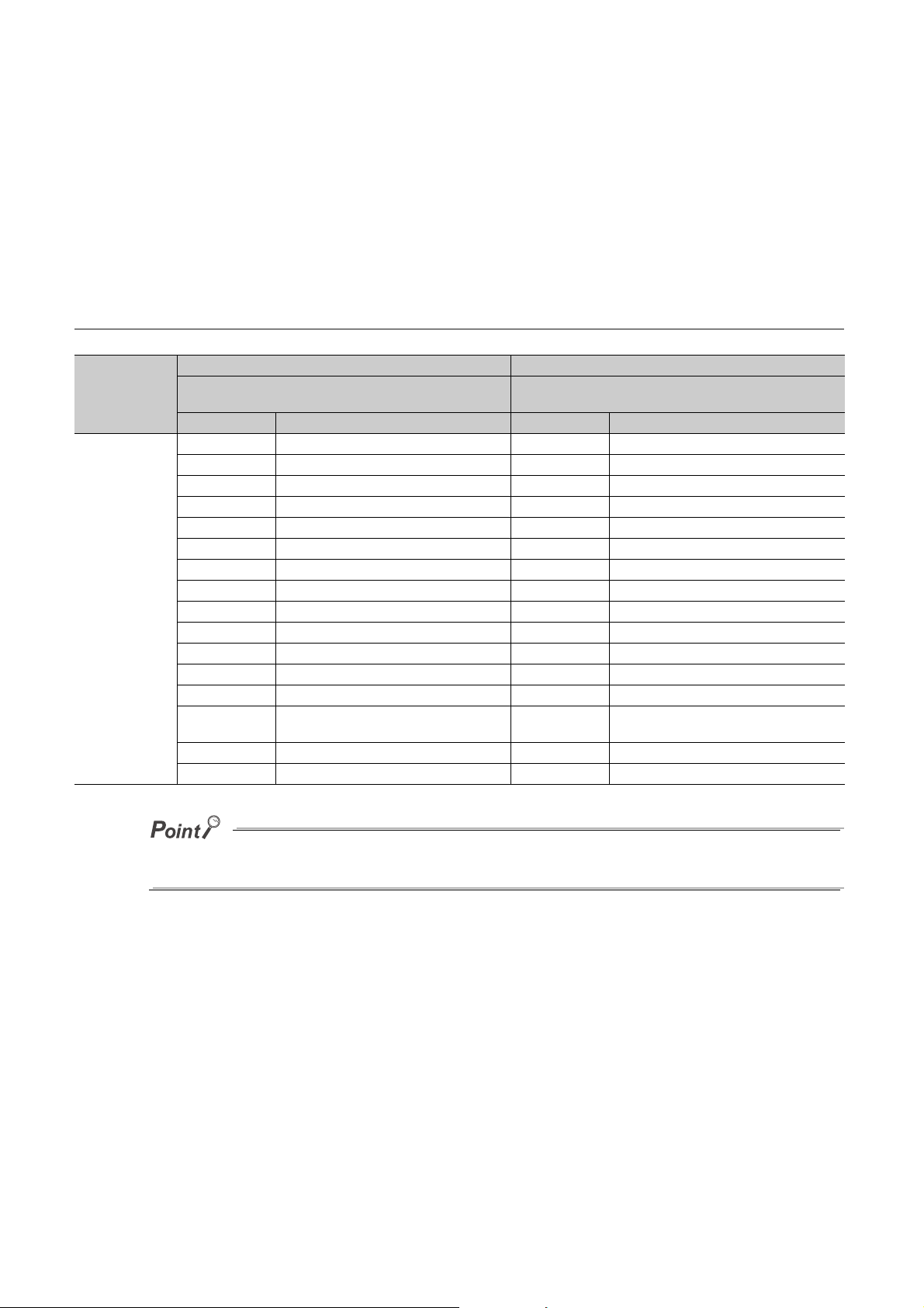
3.5.2 Extension A/D converter module
Remote input Remote output
Module type
Extension A/D
converter module
RX20 CH1 A/D conversion completed flag RY20 Use prohibited
RX21 CH2 A/D conversion completed flag RY21 Use prohibited
RX22 CH3 A/D conversion completed flag RY22 Use prohibited
RX23 CH4 A/D conversion completed flag RY23 Use prohibited
RX24 CH1 Difference conversion state flag RY24 CH1 Difference conversion trigger
RX25 CH2 Difference conversion state flag RY25 CH2 Difference conversion trigger
RX26 CH3 Difference conversion state flag RY26 CH3 Difference conversion trigger
RX27 CH4 Difference conversion state flag RY27 CH4 Difference conversion trigger
RX28 Alert output signal RY28 Use prohibited
RX29 Trigger conversion completed flag RY29 Trigger conversion request
RX2A Use prohibited RY2A Trigger conversion completed clear request
RX2B Use prohibited RY2B Use prohibited
RX2C Input signal error detection signal RY2C Use prohibited
RX2D
RX2E Use prohibited RY2E Use prohibited
RX2F External power supply READY flag RY2F Use prohibited
Signal direction: Extension A/D converter
module→Master/local module
Device No. Description Device No. Description
Maximum value/minimum value reset
completed flag
RY2D Maximum value/minimum value reset request
Signal direction: Master/local module→Extension A/D
converter module
34
Do not use any "Use prohibited" remote I/O signals. If any of the signals are used, correct operation of the module cannot be
guaranteed.
Page 37
CHAPTER 3 SPECIFICATIONS
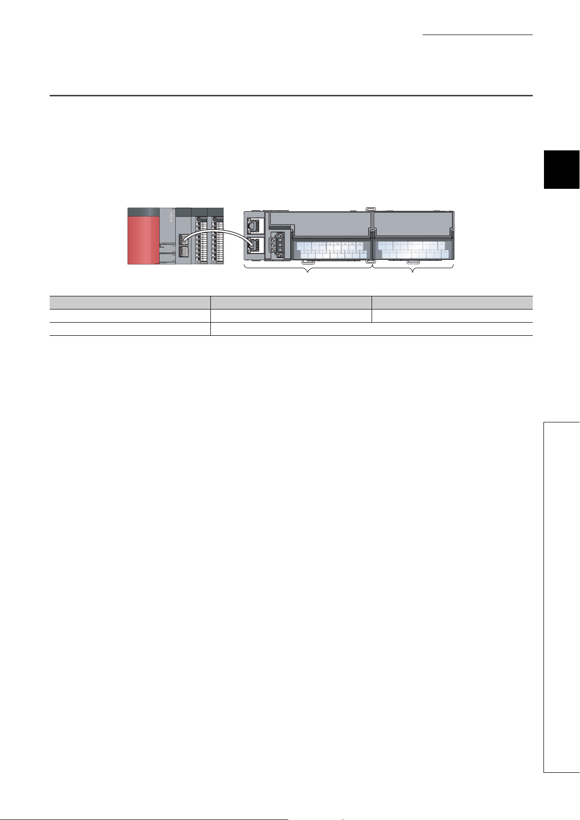
Main A/D converter module Extension module
3.6 List of Remote Registers
This section lists remote registers for a master/local module.
The remote register assignment shown assumes that the remote registers of the main module are assigned to RWr0 to
RWrF and RWw0 to RWwF.
Remote register (RWr) is the information input from A/D converter module to master/local module.
Remote register (RWw) is the information output from master/local module to A/D converter module.
The remote registers of the main A/D converter module and extension module are assigned as shown below.
Module Remote register (RWr) Remote register (RWw)
Main A/D converter module RWr0 to RWrF RWw0 to RWwF
Extension module (depends on the type of the extension module)
For details on the remote register, refer to the following:
• Page 201, Appendix 2
3
3.6 List of Remote Registers
35
Page 38
3.6.1 Main A/D converter module
Remote register (RWr) Remote register (RWw)
Module type
Main A/D
converter module
Signal direction: Main A/D converter module→Master/local
module
Device No. Description Device No. Description
RWr0 Latest error code RWw0 Use prohibited
RWr1 Latest warning code RWw1 Use prohibited
RWr2 CH1 Digital operation value RWw2 CH1 Shifting amount to conversion value
RWr3 CH2 Digital operation value RWw3 CH2 Shifting amount to conversion value
RWr4 CH3 Digital operation value RWw4 CH3 Shifting amount to conversion value
RWr5 CH4 Digital operation value RWw5 CH4 Shifting amount to conversion value
RWr6 CH1 Difference conversion reference value RWw6 Use prohibited
RWr7 CH2 Difference conversion reference value RWw7 Use prohibited
RWr8 CH3 Difference conversion reference value RWw8 Use prohibited
RWr9 CH4 Difference conversion reference value RWw9 Use prohibited
RWrA Input signal error detection flag RWwA Use prohibited
RWrB Alert output flag RWwB Use prohibited
RWrC Use prohibited RWwC Use prohibited
RWrD Use prohibited RWwD Use prohibited
RWrE Use prohibited RWwE Use prohibited
RWrF
*1
Use prohibited
Signal direction: Master/local module→Main A/D converter
module
RWwF
*1
Use prohibited
*1 The registers RWrF and RWwF are used by the system in synchronous communication mode.
Do not read/write data from/to any "Use prohibited" remote registers. If data is read or written, correct operation of the
module cannot be guaranteed.
(1) Remote registers of extension analog modules
The remote registers differ depending on the model of extension analog module.
• For the extension A/D converter module, refer to Page 37, Section 3.6.2.
• For the extension D/A converter module, refer to CC-Link IE Field Network Digital-Analog Converter
Module User's Manual.
36
Page 39
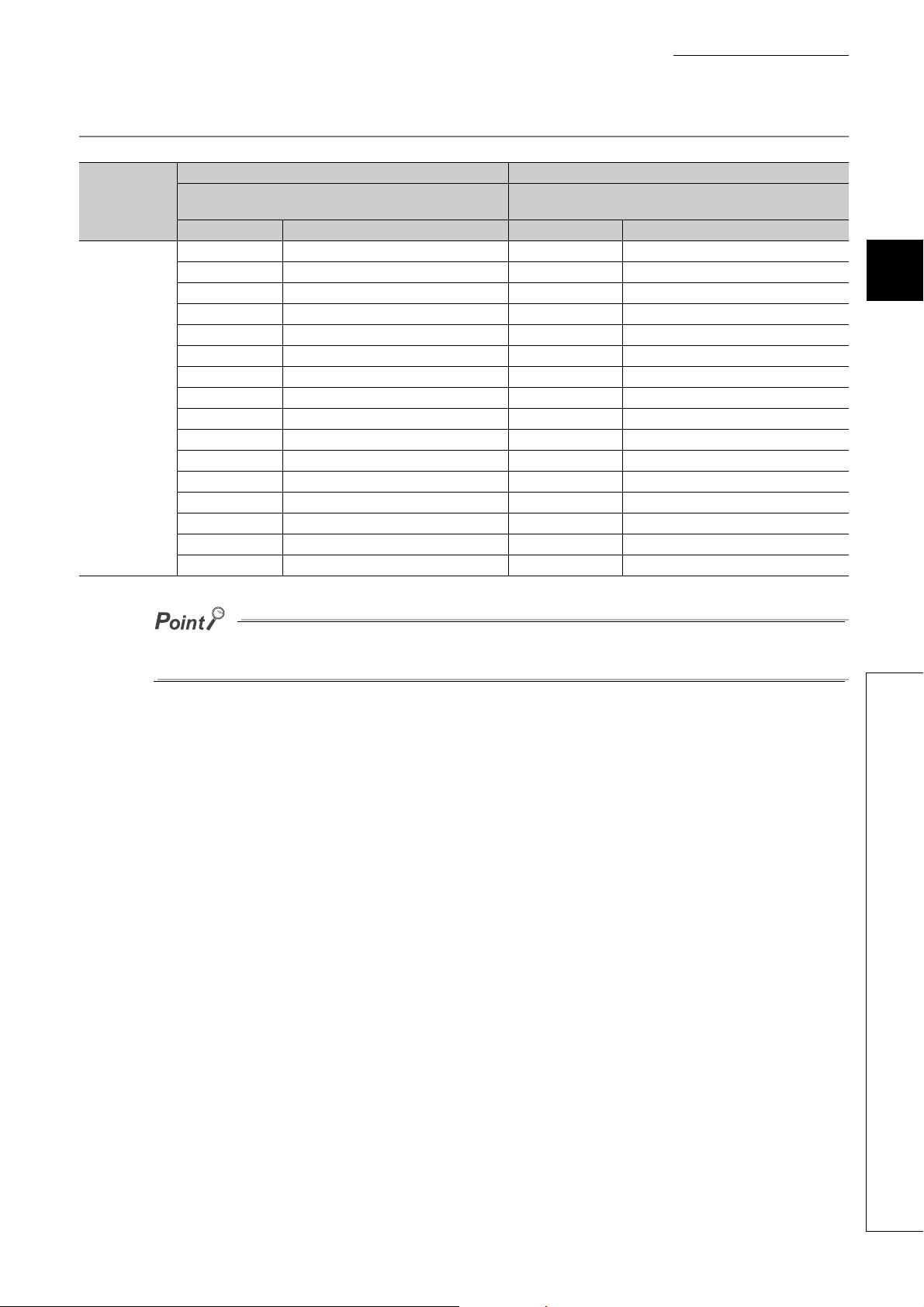
3.6.2 Extension A/D converter module
Remote register (RWr) Remote register (RWw)
Module type
Extension module
Signal direction: Extension A/D converter
module→Master/local module
Device No. Description Device No. Description
RWr10 Use prohibited RWw10 Use prohibited
RWr11 Use prohibited RWw11 Use prohibited
RWr12 CH1 Digital operation value RWw12 CH1 Shifting amount to conversion value
RWr13 CH2 Digital operation value RWw13 CH2 Shifting amount to conversion value
RWr14 CH3 Digital operation value RWw14 CH3 Shifting amount to conversion value
RWr15 CH4 Digital operation value RWw15 CH4 Shifting amount to conversion value
RWr16 CH1 Difference conversion reference value RWw16 Use prohibited
RWr17 CH2 Difference conversion reference value RWw17 Use prohibited
RWr18 CH3 Difference conversion reference value RWw18 Use prohibited
RWr19 CH4 Difference conversion reference value RWw19 Use prohibited
RWr1A Input signal error detection flag RWw1A Use prohibited
RWr1B Alert output flag RWw1B Use prohibited
RWr1C Use prohibited RWw1C Use prohibited
RWr1D Use prohibited RWw1D Use prohibited
RWr1E Use prohibited RWw1E Use prohibited
RWr1F Use prohibited RWw1F Use prohibited
Signal direction: Master/local module→Extension A/D converter
CHAPTER 3 SPECIFICATIONS
module
3
Do not read or write the data from/to any "Use prohibited" remote registers. If data is read or written, correct operation of the
module cannot be guaranteed.
3.6 List of Remote Registers
37
Page 40
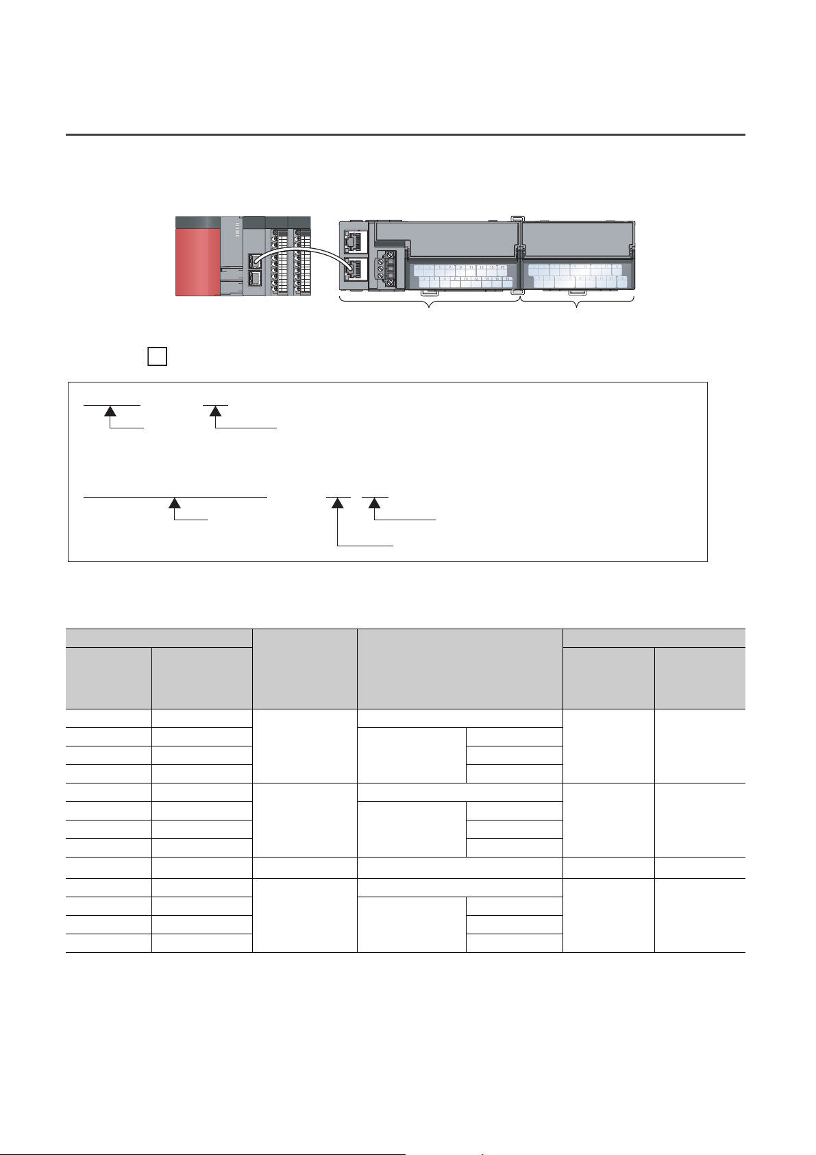
3.7 List of Remote Buffer Memory Areas
Ex.
Main A/D converter module Extension module
Setting item
A/D conversion enable/disable setting (address: 0102H, 0202H)
Address of the extension A/D converter module
Address of the main A/D converter module
Setting item
Mode switch (address: 0000H)
Address of the main A/D converter module
This section lists the remote buffer memory areas of the A/D converter module.
The remote buffer memory areas of the main module and extension module are assigned as shown below.
How the individual areas of remote buffer memory are shown in the manual
For details on the remote buffer memory, refer to the following:
• Page 205, Appendix 3
Remote buffer memory address
Decimal Hexadecimal
0 to 255 0000H to 00FFH
256 to 511 0100H to 01FFH
512 to 767 0200H to 02FFH Extension module 1
768 to 1279 0300H to 04FFH System area
1280 to 1535 0500H to 05FFH
1536 to 1791 0600H to 06FFH
1792 to 2047 0700H to 07FFH Extension module 1
2048 to 2559 0800H to 09FFH System area
2560 to 4095 0A00H to 0FFFH Error history area Station-based error history data
4096 to 4351 1000H to 10FFH
4352 to 4607 1100H to 11FFH
4608 to 4863 1200H to 12FFH Extension module 1
4864 to 5375 1300H to 14FFH System area
*1 For the REMFR and REMTO instructions, refer to the following:
*2 For the access method, refer to the following:
Area Ta rge t
Station-based parameter data
Parameter area
Monitor area
Module control data
area
Module-based
parameter data
Station-based monitor data
Module-based monitor
data
Station-based control data
Module-based control
data
User's manual for the master/local module used
• Parameter area ( Page 69, Section 7.1)
• Error history area ( Page 168, Section 11.1)
: Access permitted, : Access not permitted
Access method
REMFR
instruction,
REMTO
instruction
Main module
Main module
Main module
CC IE Field
configuration of
the engineering
tool
*2
*2
*1
38
Page 41
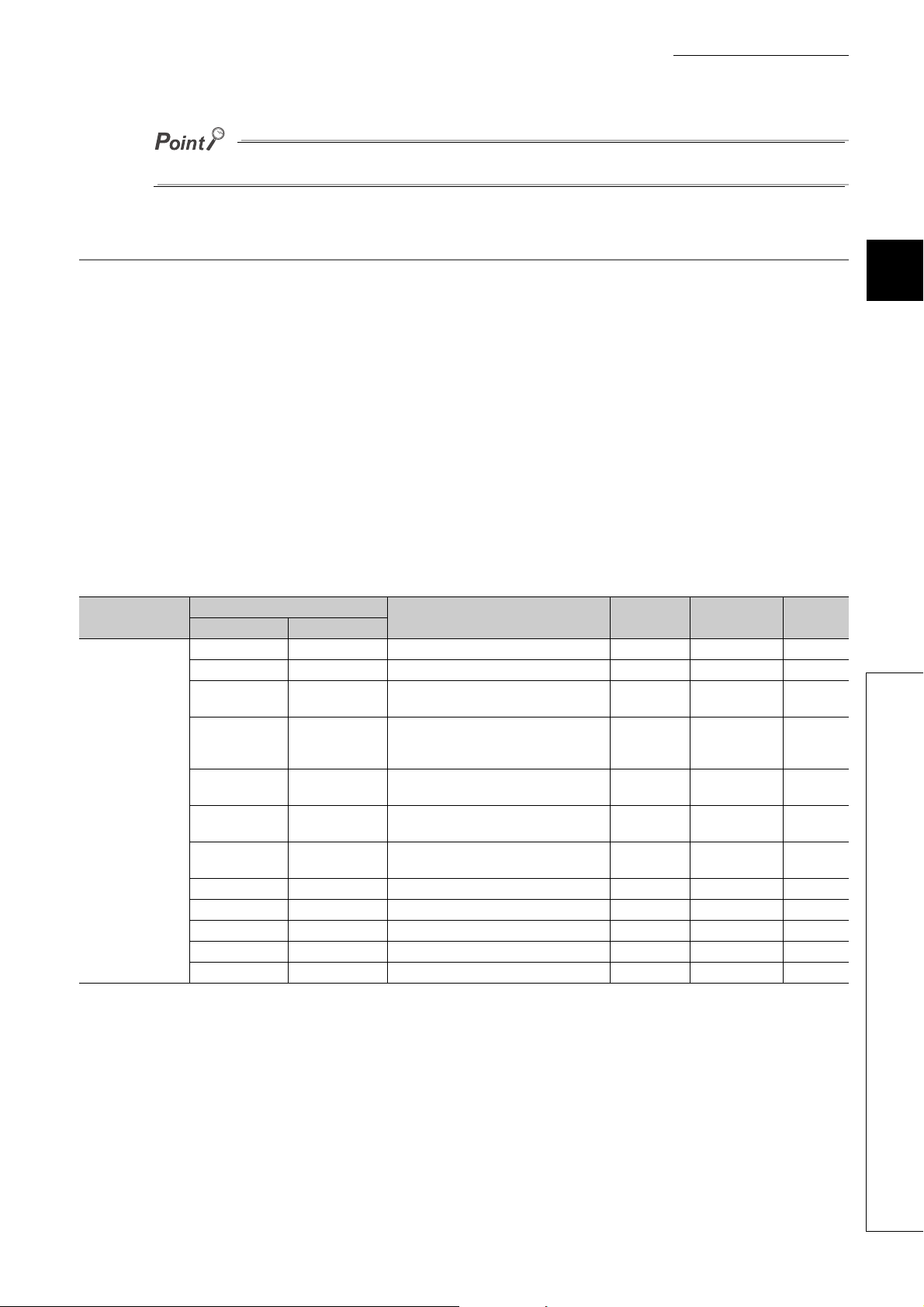
Do not access any system area using the REMFR or REMTO instruction. Doing so may cause malfunction.
3.7.1 Main A/D converter module
(1) Parameter area (address: 0000H to 04FFH)
For the parameter area, parameters can be set by means of the CC IE Field configuration of the engineering tool,
or the REMTO instruction.
The parameters in the parameter area are backed up to the non-volatile memory.
The parameters backed up to the non-volatile memory are read out to the parameter area when the module
power supply is turned off and on or the module is reset by remote reset.
For the parameters written from the parameter settings of the CC IE Field configuration of the engineering tool,
the write to the non-volatile memory is also completed at the same time. For the parameters written using the
REMTO instruction, the timing of the write to the non-volatile memory is at the time of turning on Initial data
setting request flag (RY9) from off. At this time, even an invalid parameter is written to the non-volatile memory as
well. With an invalid parameter written, turning off and on the power supply causes the invalid parameter to be
read from the non-volatile memory, resulting in the error code being stored into Latest error code (RWr0). Take
corrective action with reference to the error code list. ( Page 172, Section 11.2)
Typ e
Station-based
parameter data
Decimal Hexadecimal
0 0000H Mode switch 0009H R/W
1 0001H Conversion speed switch 0000H R/W
2 0002H
3 0003H
4 0004H
5 0005H
6 0006H
7 0007H Cyclic data update watch time setting 0000H R/W
8 to 15 0008H to 000FH System area
16 0010H Input response time setting 0005H R/W
17 0011H Digital output HOLD/CLEAR setting 0000H R/W
18 to 255 0012H to 00FFH System area
Address
Description
Trigger conversion signal assignment (for
external signal assignment function)
Input signal error detection signal
assignment (for external signal assignment
function)
Alert output signal assignment (for external
signal assignment function)
Error flag assignment (for external signal
assignment function)
Warning flag assignment (for external signal
assignment function)
CHAPTER 3 SPECIFICATIONS
Default
value
FFFFH R/W
FFFFH R/W
FFFFH R/W
FFFFH R/W
FFFFH R/W
Read/Write
*1
*2
Necessity
*3
of RY9
3
3.7 List of Remote Buffer Memory Areas
39
Page 42

Typ e
Main module
Module-based
parameter data
Extension module 1
Module-based
parameter data
768 to 1279 0300H to 04FFH System area
Decimal Hexadecimal
256, 257 0100H, 0101H System area
258 0102H A/D conversion enable/disable setting 0000H R/W
259 0103H Range setting 0000H R/W
260 0104H Averaging process setting 0000H R/W
261 0105H
262 0106H
263 0107H
264 0108H
265 0109H Input signal error detection setting 0000H R/W
266 to 269 010AH to 010DH System area
270 010EH Alert output setting 000FH R/W
271 010FH CH1 Process alarm lower lower limit value 0 R/W
272 0110H CH1 Process alarm lower upper limit value 0 R/W
273 0111H CH1 Process alarm upper lower limit value 0 R/W
274 0112H CH1 Process alarm upper upper limit value 0 R/W
275 0113H CH2 Process alarm lower lower limit value 0 R/W
276 0114H CH2 Process alarm lower upper limit value 0 R/W
277 0115H CH2 Process alarm upper lower limit value 0 R/W
278 0116H CH2 Process alarm upper upper limit value 0 R/W
279 0117H CH3 Process alarm lower lower limit value 0 R/W
280 0118H CH3 Process alarm lower upper limit value 0 R/W
281 0119H CH3 Process alarm upper lower limit value 0 R/W
282 011AH CH3 Process alarm upper upper limit value 0 R/W
283 011BH CH4 Process alarm lower lower limit value 0 R/W
284 011CH CH4 Process alarm lower upper limit value 0 R/W
285 011DH CH4 Process alarm upper lower limit value 0 R/W
286 011EH CH4 Process alarm upper upper limit value 0 R/W
287 011FH Digital clipping enable/disable setting 000FH R/W
288 0120H Scaling enable/disable setting 000FH R/W
289 0121H CH1 Scaling lower limit value 0 R/W
290 0122H CH1 Scaling upper limit value 0 R/W
291 0123H CH2 Scaling lower limit value 0 R/W
292 0124H CH2 Scaling upper limit value 0 R/W
293 0125H CH3 Scaling lower limit value 0 R/W
294 0126H CH3 Scaling upper limit value 0 R/W
295 0127H CH4 Scaling lower limit value 0 R/W
296 0128H CH4 Scaling upper limit value 0 R/W
297 to 511 0129H to 01FFH System area
512 to 767 0200H to 02FFH
Address
Description
CH1 Time average/Count average/Moving
average
CH2 Time average/Count average/Moving
average
CH3 Time average/Count average/Moving
average
CH4 Time average/Count average/Moving
average
The remote buffer memory areas of the
connected extension module are assigned.
Default
value
0R/W
0R/W
0R/W
0R/W
Read/Write
*1
*2
Necessity
*3
of RY9
*1 This value is the value of factory default or the value of initialization by Parameter area initialization command (address:
1002H).
*2 This shows whether reading/writing data from/to a program is possible.
R: Readable
W: Writable
*3 This shows the items enabled by turning on and off Initial data setting request flag (RY9).
40
Page 43

CHAPTER 3 SPECIFICATIONS
(a) Parameter area of extension modules
The remote buffer memory areas differ depending on the model of extension module.
• For the extension A/D converter module, refer to Page 44, Section 3.7.2 (1).
• For the extension D/A converter module, refer to CC-Link IE Field Network Digital-Analog Converter
Module User's Manual.
• For the extension I/O module, refer to CC-Link IE Field Network Remote I/O Module User's Manual.
(2) Monitoring area (address: 0500H to 09FFH)
Typ e
Station-based monitor
data
Main module
Module-based monitor
data
Extension module 1
Module-based monitor
data
2048 to 2559 0800H to 09FFH System area
Decimal Hexadecimal
1280 to 1535 0500H to 05FFH System area
1536 0600H System area
1537 0601H CH1 Maximum value 0 R
1538 0602H CH1 Minimum value 0 R
1539 0603H CH2 Maximum value 0 R
1540 0604H CH2 Minimum value 0 R
1541 0605H CH3 Maximum value 0 R
1542 0606H CH3 Minimum value 0 R
1543 0607H CH4 Maximum value 0 R
1544 0608H CH4 Minimum value 0 R
1545 to 1791 0609H to 06FFH System area
1792 to 2047 0700H to 07FFH
Address
Description
The remote buffer memory areas of the
connected extension module are assigned.
*1 Value at the time of turning off and on the module power supply or at the time of remote reset.
*2 This shows whether reading/writing data from/to a program is possible.
R: Readable
W: Writable
Default
value
Read/Write
*1
*2
3
3.7 List of Remote Buffer Memory Areas
(a) Monitor area of extension modules
The remote buffer memory differs depending on the model of the extension module.
• For the extension A/D converter module, refer to Page 45, Section 3.7.2 (2).
• For the extension D/A converter module, refer to CC-Link IE Field Network Digital-Analog Converter
Module User's Manual.
• For the extension I/O module, refer to CC-Link IE Field Network Remote I/O Module User's Manual.
41
Page 44

(3) Error history area (address: 0A00H to 0FFFH)
Typ e
Station-based error
history data
Decimal Hexadecimal
2560 0A00H
2561 0A01H Order of generation 0000H R
2562 0A02H
2563 0A03H [Error time] Month/Day 0000H R
2564 0A04H [Error time] Hour/Minute 0000H R
2565 0A05H
2566 0A06H CH1 Digital operation value 0000H R
2567 0A07H CH2 Digital operation value 0000H R
2568 0A08H CH3 Digital operation value 0000H R
2569 0A09H CH4 Digital operation value 0000H R
2570 to 2575 0A0AH to 0A0FH System area
2576 to 2591 0A10H to 0A1FH Error history data 2 Same as Error history data 1.
2592 to 2607 0A20H to 0A2FH Error history data 3 Same as Error history data 1.
2608 to 2623 0A30H to 0A3FH Error history data 4 Same as Error history data 1.
2624 to 2639 0A40H to 0A4FH Error history data 5 Same as Error history data 1.
2640 to 2655 0A50H to 0A5FH Error history data 6 Same as Error history data 1.
2656 to 2671 0A60H to 0A6FH Error history data 7 Same as Error history data 1.
2672 to 2687 0A70H to 0A7FH Error history data 8 Same as Error history data 1.
2688 to 2703 0A80H to 0A8FH Error history data 9 Same as Error history data 1.
2704 to 2719 0A90H to 0A9FH Error history data 10 Same as Error history data 1.
2720 to 2735 0AA0H to 0AAFH Error history data 11 Same as Error history data 1.
2736 to 2751 0AB0H to 0ABFH Error history data 12 Same as Error history data 1.
2752 to 2767 0AC0H to 0ACFH Error history data 13 Same as Error history data 1.
2768 to 2783 0AD0H to 0ADFH Error history data 14 Same as Error history data 1.
2784 to 2799 0AE0H to 0AEFH Error history data 15 Same as Error history data 1.
2800 to 4095 0AF0H to 0FFFH System area
Address
Error history data 1
Description
Error code 0000H R
[Error time] First two digits of
the year/Last two digits of the
year
[Error time] Second/00H
(Fixed)
Default
value
0000H R
0000H R
Read/Write
*1
*2
*1 This value is the value of factory default or the value of initialization by Error history clear command (address: 1000H).
*2 This shows whether reading/writing data from/to a program is possible.
R: Readable
W: Writable
42
Page 45

CHAPTER 3 SPECIFICATIONS
(4) Module control data area (address: 1000H to 14FFH)
Typ e
Station-based control
data
Station-based control
data
Main module
Module-based control
data
Extension module 1
Module-based control
data
4864 to 5375 1300H to 14FFH System area
Decimal Hexadecimal
4096 1000H Error history clear command 0 R/W
4097 1001H Error history clear completed 0 R
4098 1002H Parameter area initialization command 0 R/W
4099 1003H Parameter area initialization completed 0 R
4100 1004H
4101 1005H
4102 to 4351 1006H to 10FFH System area
4352 to 4607 1100H to 11FFH System area
4608 to 4863 1200H to 12FFH
Address
Description
Module operation information initialization
command
Module operation information initialization
completed
The remote buffer memory areas of the
connected extension module are assigned.
Default
value
0R/W
0R
Read/Write
*1
*2
3
*1 Value at the time of turning off and on the module power supply or at the time of remote reset.
*2 This shows whether reading/writing data from/to a program is possible.
R: Readable
W: Writable
(a) Module control data area of the extension module
The remote buffer memory differs depending on the model of the extension module.
• For the extension A/D converter module, refer to Page 45, Section 3.7.2 (3).
• For the extension D/A converter module, refer to CC-Link IE Field Network Digital-Analog Converter
Module User's Manual.
• For the extension I/O module, refer to CC-Link IE Field Network Remote I/O Module User's Manual.
3.7 List of Remote Buffer Memory Areas
43
Page 46

3.7.2 Extension A/D converter module
(1) Parameter area (address: 0200H to 02FFH)
Typ e
Extension module
Module-based
parameter data
Decimal Hexadecimal
512 0200H Extension module identification code 0000H R/W
513 0201H System area
514 0202H A/D conversion enable/disable setting 0000H R/W
515 0203H Range setting 0000H R/W
516 0204H Averaging process setting 0000H R/W
517 0205H
518 0206H
519 0207H
520 0208H
521 0209H Input signal error detection setting 0000H R/W
522 to 525 020AH to 020DH System area
526 020EH Alert output setting 000FH R/W
527 020FH CH1 Process alarm lower lower limit value 0 R/W
528 0210H CH1 Process alarm lower upper limit value 0 R/W
529 0211H CH1 Process alarm upper lower limit value 0 R/W
530 0212H CH1 Process alarm upper upper limit value 0 R/W
531 0213H CH2 Process alarm lower lower limit value 0 R/W
532 0214H CH2 Process alarm upper lower limit value 0 R/W
533 0215H CH2 Process alarm upper lower limit value 0 R/W
534 0216H CH2 Process alarm upper upper limit value 0 R/W
535 0217H CH3 Process alarm lower lower limit value 0 R/W
536 0218H CH3 Process alarm lower upper limit value 0 R/W
537 0219H CH3 Process alarm upper lower limit value 0 R/W
538 021AH CH3 Process alarm upper upper limit value 0 R/W
539 021BH CH4 Process alarm lower lower limit value 0 R/W
540 021CH CH4 Process alarm lower upper limit value 0 R/W
541 021DH CH4 Process alarm upper lower limit value 0 R/W
542 021EH CH4 Process alarm upper upper limit value 0 R/W
543 021FH Digital clipping enable/disable setting 000FH R/W
544 0220H Scaling enable/disable setting 000FH R/W
545 0221H CH1 Scaling lower limit value 0 R/W
546 0222H CH1 Scaling upper limit value 0 R/W
547 0223H CH2 Scaling lower limit value 0 R/W
548 0224H CH2 Scaling upper limit value 0 R/W
549 0225H CH3 Scaling lower limit value 0 R/W
550 0226H CH3 Scaling upper limit value 0 R/W
551 0227H CH4 Scaling lower limit value 0 R/W
552 0228H CH4 Scaling upper limit value 0 R/W
553 to 767 0229H to 02FFH System area
Address
Description
CH1 Time average/Count average/Moving
average
CH2 Time average/Count average/Moving
average
CH3 Time average/Count average/Moving
average
CH4 Time average/Count average/Moving
average
Default
value
0R/W
0R/W
0R/W
0R/W
Read/Write
*1
*2
Necessity
*3
of RY9
44
Page 47

*1 This value is the value of factory default or the value of initialization by Parameter area initialization command (address:
1002H).
*2 This shows whether reading/writing data from/to a program is possible.
R: Readable
W: Writable
*3 This shows the items enabled by turning on and off Initial data setting request flag (RY9).
(2) Monitor area (address: 0700H to 07FFH)
Typ e
Extension module 1
Module-based monitor
data
Decimal Hexadecimal
1792 0700H Extension module identification code 0000H R
1793 0701H CH1 Maximum value 0 R
1794 0702H CH1 Minimum value 0 R
1795 0703H CH2 Maximum value 0 R
1796 0704H CH2 Minimum value 0 R
1797 0705H CH3 Maximum value 0 R
1798 0706H CH3 Minimum value 0 R
1799 0707H CH4 Maximum value 0 R
1800 0708H CH4 Minimum value 0 R
1801 to 2047 0709H to 07FFH System area
Address
Description
CHAPTER 3 SPECIFICATIONS
Default
value
Read/Write
*1
*2
3
*1 Value at the time of turning off and on the module power supply or at the time of remote reset.
*2 This shows whether reading/writing data from/to a program is possible.
R: Readable
W: Writable
(3) Module control data area (address: 1200H to 12FFH)
Typ e
Extension module 1
Module-based control
data
*1 Value at the time of turning off and on the module power supply or at the time of remote reset.
*2 This shows whether reading/writing data from/to a program is possible.
Decimal Hexadecimal
4608 to 4863 1200H to 12FFH System area
R: Readable
W: Writable
Address
Description
Default
value
Read/Write
*1
*2
3.7 List of Remote Buffer Memory Areas
45
Page 48
CHAPTER 4 PROCEDURES BEFORE OPERATION
Set the station number of the main A/D converter module.
Setting a station number
Check box
Connection
When using an extension module, connect the extension module to the
main A/D converter module.
After that, mount the main A/D converter module on a DIN rail.
Carry out wiring of a power supply, Ethernet cables, and external
devices to the main A/D converter module.
To use an extension module, carry out wiring of a power supply
and external devices to the extension module.
Wiring
Parameter settings and programming
Set parameters and create a program.
Offset/gain setting
If the user range is necessary, set up the offset/gain setting.
This chapter describes the procedures before operation.
Page 50, Section 6.1
Page 51, Section 6.2
Page 53, Section 6.3
*1 To replace the module, refer to the point below.
Page 53, Section 6.3
Page 58, Section 6.4
Page 60, Section 6.5
Page 69, Section 7.1
Page 76, Section 7.2
Page 155, CHAPTER 9
Page 83, Section 7.3
*1
To replace the module, follow the procedure described below:
• Turn off the module power supply and remove the A/D converter module.
• Prepare a new A/D converter module and follow the illustration above as instructed from "Setting a station
number" to "Parameter settings and programming". (No re-setting of network parameters of the master station is
required.)
• If necessary to use the user range, perform the offset/gain setting.
• Carry out operation check and then restart the control.
46
Page 49

Memo
CHAPTER 4 PROCEDURES BEFORE OPERATION
4
47
Page 50
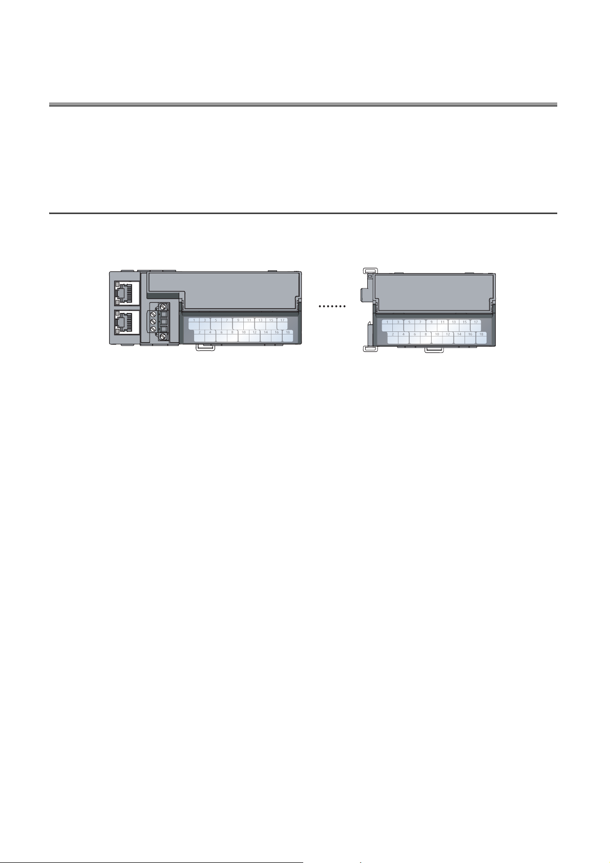
CHAPTER 5 SYSTEM CONFIGURATION
Main A/D converter module Extension module
This chapter describes how to configure the system using A/D converter modules.
For the configuration on CC-Link IE Field Network, refer to the following:
User's manual for the master/local module used
5.1 System Configuration with A/D Converter Module
The following figure shows the system configuration including an A/D converter module.
48
Page 51
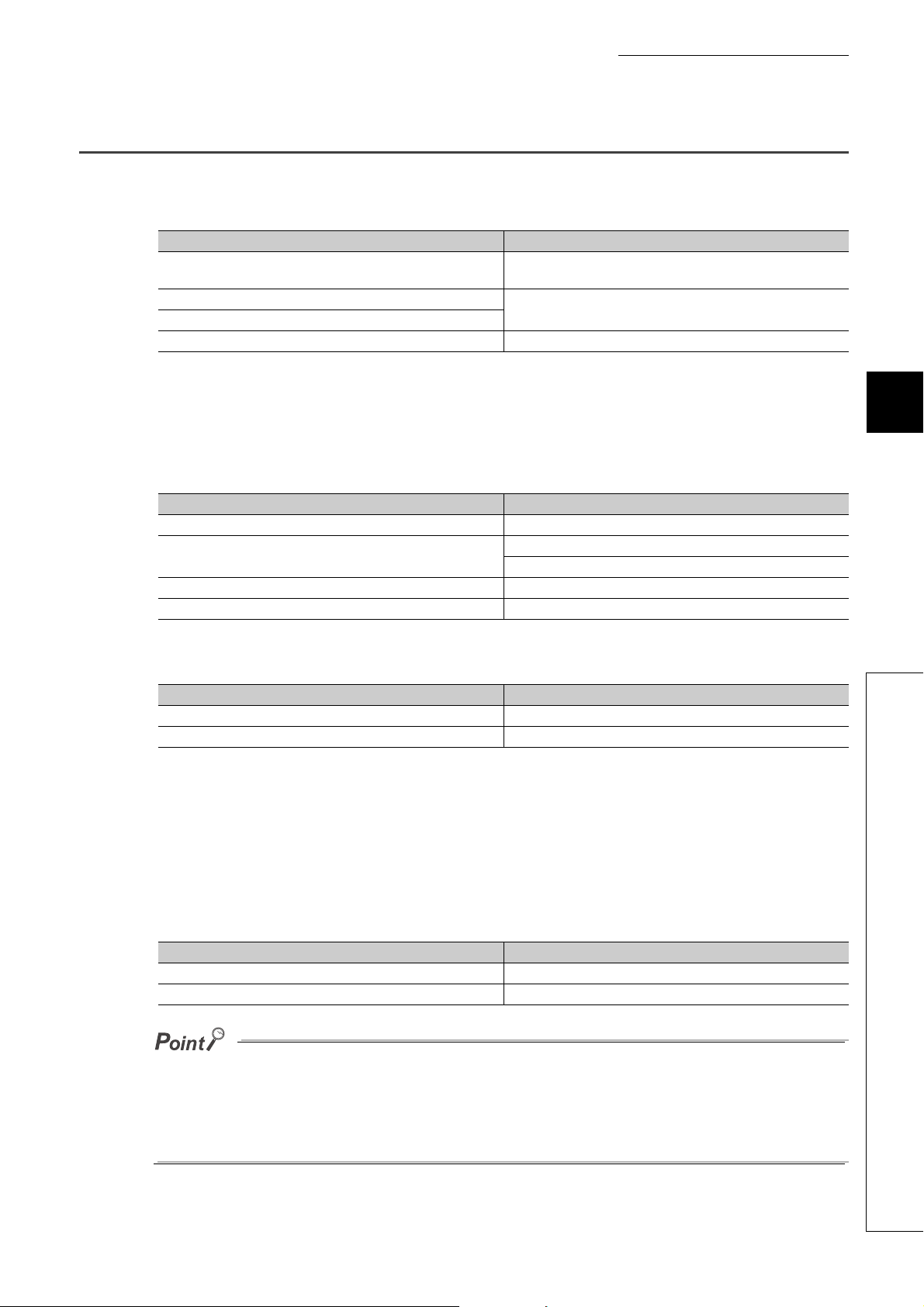
5.2 Applicable Systems
(1) Supported master station
For the use of an A/D converter module, select a product for the master station from the following list.
Model First five digits of serial number
RJ71GF11-T2
RJ71EN71
LJ71GF11-T2
QJ71GF11-T2
QD77GF16 14111 or later
A master station other than the above does not allow the use of the A/D converter module.
CHAPTER 5 SYSTEM CONFIGURATION
(no restriction)
14102 or later
(2) Connectable modules
(a) Extension modules that can be connected to the main A/D converter module
Either one of the following extension modules can be connected to the main A/D converter module.
Classification Model
Extension input module NZ2EX2B1-16D
Extension output module
Extension A/D converter module NZ2EX2B-60AD4
Extension D/A converter module NZ2EX2B-60DA4
NZ2EX2B1-16T
NZ2EX2B1-16TE
(b) Main modules to which the extension A/D converter module can be connected
The extension A/D converter module can be connected to either one of the following main modules.
Classification Model
Main A/D converter module NZ2GF2BN-60AD4
Main D/A converter module NZ2GF2BN-60DA4
(3) Ethernet cables
For the specifications of the Ethernet cable, refer to the following:
User's manual for the master/local module used
5
5.2 Applicable Systems
(4) Supported software package
Configuring and diagnosing the A/D converter module requires GX Works2 or GX Works3. According the master
station used, install the following version of GX Works2 or GX Works3.
Engineering tool Software version
GX Works2 Version 1.525X or later
GX Works3 Version 1.005F or later
When the latest profile of the A/D converter module is necessary, please consult your local Mitsubishi representative.
The profile is a setting file that stores information required for the start-up, operation, and maintenance of devices supporting
the CC-Link family. A module is added to "Module List" of "CC IE Field Configuration" window by profile registration to GX
Works2 or GX Works3. For the profile registration, refer to the following.
GX Works2 Version 1 Operating Manual (Common)
GX Works3 Operating Manual
49
Page 52
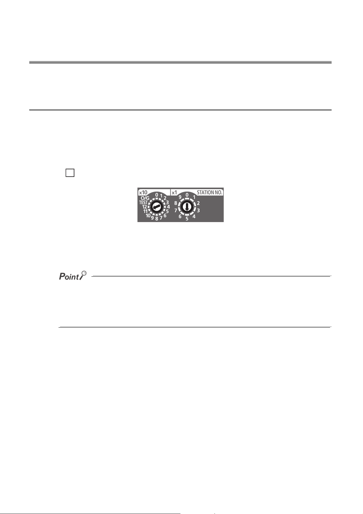
CHAPTER 6 INSTALLATION AND WIRING
Ex.
This chapter describes the installation and wiring of the A/D converter module.
6.1 Station Number Setting
(1) Setting method
Set the station number with the rotary switch on the front of the module. Set the station number in the power-off
state because the set value is enabled at power-on.
• The dial x10 is used to set the hundreds and tens place of a station number.
• The dial x1 is used to set the ones place of a station number.
For the station number 115, set the switch as shown below.
(2) Setting range
Set the station number, which can be from 1 to 120. A value other than 1 to 120 causes a communication error,
resulting in the D LINK LED flashing.
● While the module power supply is in an on state, changing the station number setting switch causes a minor error,
resulting in the ERR. LED flashing.
When the station number setting switch is set back to the previous state, the module recovers from the error after five
seconds, resulting in the ERR. LED turning off.
● For the station number setting, avoid duplication with the other station numbers. Number duplication causes a
communication error, which does not allow the D LINK LED to light up.
50
Page 53

CHAPTER 6 INSTALLATION AND WIRING
60mm
or longer
60mm
or longer
60mm
or longer
60mm
or longer
60mm
or longer
60mm
or longer
60mm
or longer
6.2 Installation Environment and Installation Position
6.2.1 Installation environment
(1) Installation location
Do not install the A/D converter module in places where:
• Ambient temperature is outside the range of 0 to 55;
• Ambient humidity is outside the range of 5 to 95% RH;
• Condensation occurs due to rapid temperature change;
• Corrosive gas or combustible gas is present;
• There are a high level of conductive powder such as dust and iron powder, oil mist, salinity, or organic
solvent;
• It is exposed to direct sunlight;
• A strong electric field or strong magnetic field is generated; and
• The module is subject to vibration and shock.
6
(2) Installation surface
Install the A/D converter module on a flat surface. Unevenness on the installation surface causes application of
an excessive force to the printed-circuit board, which may lead to a malfunction.
6.2.2 Installation position
When installing the A/D converter module in a control panel, provide a clearance of at least 60mm from the
surroundings including adjacent structures and modules to ensure good ventilation and easy module change.
6.2 Installation Environment and Installation Position
51
Page 54
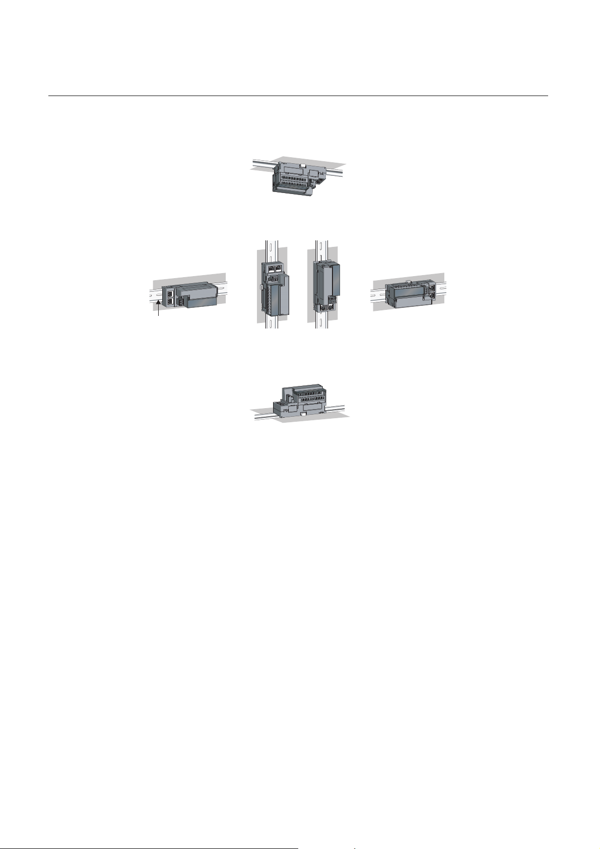
6.2.3 Installation direction
The A/D converter module can be installed in six directions.
Use a DIN rail to install the module.
Downward installation
DIN rail
Vertical installation Horizontal installation Horizontal installation
Upward installation
(upside down)
52
Page 55
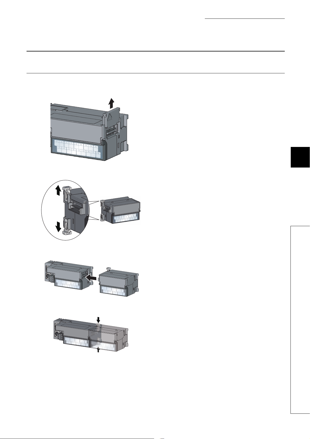
6.3 Installation
Release
Lock
Lock
6.3.1 How to connect an extension module
(1) Connecting procedure
1. Remove the cover on the side of the main module.
Save the removed cover without losing it.
CHAPTER 6 INSTALLATION AND WIRING
6
2. Release the module joint levers (two points) on the
side of the extension module. Slide the levers
vertically.
3. Insert one module straight into the other so that the
connectors of both modules engage.
4. Lock the module joint levers (two points) on the
side of the extension module. Slide the levers
toward the module.
Check that the modules are securely connected.
6.3 Installation
53
Page 56

(2) Disconnecting procedure
Disconnect the extension module in a procedure opposite to the connecting procedure.
● Shut off the external power supply for the system in all phases before connecting or disconnecting extension modules.
● Lock the module joint levers securely. Failure to do so may cause malfunction, failure, or drop of the module.
54
Page 57
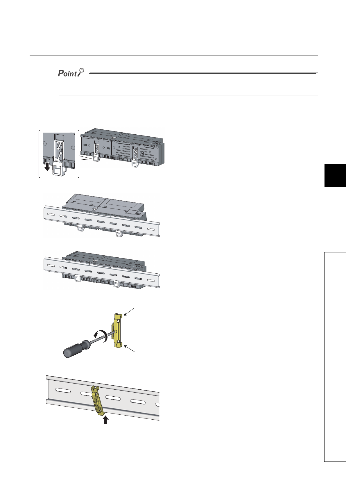
6.3.2 How to mount modules on a DIN rail
Hook
Hook
Engage the hook on
the bottom side of the DIN rail.
The usage instructions for a DIN rail stopper is shown as one example. Fix the module according to the manual of the DIN
rail stopper used.
(1) Mounting procedure
1. Pull down all DIN rail hooks on the back of the
modules.
The levers should be pulled down until it clicks.
CHAPTER 6 INSTALLATION AND WIRING
6
2. Hang the upper tabs of the modules on a DIN rail,
and push the modules in position.
3. Lock the DIN rail hooks to the DIN rail to secure the
modules in position.
Push each hook up until it clicks. If the hooks are
beyond the reach, use a tool such as a screwdriver.
4. Loosen the screw on the DIN rail stopper.
6.3 Installation
5. Hitch the bottom hook of the DIN rail stopper to the
bottom of the DIN rail.
Hitch the hook according to the orientation of the arrow
on the front of the stopper.
55
Page 58

6. Hitch the upper hook of the DIN rail stopper to the
Engage the hook on
the top side of the DIN rail.
DIN rail
stopper
DIN rail
stopper
DIN rail stopper
top of the DIN rail.
7. Slide the DIN rail stopper up to the left side of the
modules.
8. Hold the DIN rail stopper in the direction opposite to
the arrow on the stopper and tighten the screw with
a screwdriver.
9. Install the DIN rail stopper on the right side of the
module in the same procedure.
For the installation on the right side, be aware that the
orientation of the DIN rail stopper is upside down.
Do not slide modules from the edge of the DIN rail when mounting them. Doing so may damage the metal part located on the
back of the module.
56
Page 59

CHAPTER 6 INSTALLATION AND WIRING
(2) Removal procedure
Remove the modules from the DIN rail in a procedure opposite to the mounting procedure.
(3) Applicable DIN rail model (compliant with IEC 60715)
• TH35-7.5Fe
• TH35-7.5Al
(4) Space between DIN rail mounting screws
When installing a DIN rail, tighten the screws at a pitch of 200mm or less.
(5) DIN rail stopper
Use a stopper that is attachable to the DIN rail.
6
6.3 Installation
57
Page 60

6.4 Wiring to Terminal Block for Module Power Supply and
FG
This section describes how to wire a terminal block for module power supply and FG to the main A/D converter
module.
Note that the descriptions are the same for the extension A/D converter module.
(1) Tightening torque
Tighten the terminal block screws within the following specified torque range.
Tightening the screws too much may damage the module case.
Screw type Tightening torque range
Terminal block mounting screw (M2.5) 0.2 to 0.3N⋅m
Terminal screw (M2.5) 0.5 to 0.6N⋅m
(2) Suitable wire
The table below shows the suitable wire for connection to the terminal block for module power supply and FG.
Diameter Typ e Material Temperature rating
20 to 16 AWG Stranded Copper 75 or higher
(3) Installing and removing the terminal block
To remove the terminal block, loosen the terminal block mounting screw with a flathead screwdriver.
To install the terminal block, tighten the terminal block mounting screw with a flathead screwdriver.
Failure to secure the terminal block may cause drop, short circuit, or malfunction.
58
Page 61

CHAPTER 6 INSTALLATION AND WIRING
(4) Connecting and disconnecting a cable
To connect a cable, with the terminal screw loosened using a flathead screwdriver, insert the wire and then
tighten the terminal screw.
To disconnect the cable, with the terminal screw loosened using a flathead screwdriver, pull out the wire.
6
(5) Cable terminal processing
Strip the cable sheath approximately 10mm from the end.
To use a bar solderless terminal, connect it to the stripped part.
Cable
Approx. 10mm
(6) List of bar solderless terminals
The following table lists recommended bar solderless terminals.
Product name Model Applicable wire size Contact
TE 0.5-10 0.5
Bar solderless terminal
Bar solderless terminal tool NH79
Bar solderless terminal
Bar solderless terminal tool CRIMPFOX6
TE 0.75-10 0.75
TE 1.0-10 0.9 to 1.0
TE 1.5-10 1.25 to 1.5
AI 0.5-10WH 0.5
AI 0.75-10GY 0.75
AI 1-10RD 1.0
AI 1.5-10BK 1.5
6.4 Wiring to Terminal Block for Module Power Supply and FG
NICHIFU Co., Ltd.
Phoenix Contact Co., Ltd.
59
Page 62

6.5 Wiring of Ethernet Cable
(1) Connecting an Ethernet cable
(a) Connecting
1. Turn off the module power supply of the main A/D
converter module and the power supply of the
external devices.
2. With attention to the orientation of the cable, push
the Ethernet cable connector into the main A/D
converter module until it clicks.
3. Power on the module.
4. Power on the external device.
5. Check if the LINK LED on the port into which the
Ethernet cable is connected is on.
60
Page 63

CHAPTER 6 INSTALLATION AND WIRING
Both can be used.
Connection from port 1 to port 1,
and from port 2 to port 2
Connection from
port 1 to port 2
● The time taken for the LINK LED to turn on after connection of the cable may vary. The LINK LED normally turns on in a
few second. However, if link-up processing is repeated due to a condition of a device on the line, the longer time may be
required. If the LINK LED does not turn on, refer to the following and take a corrective action.
Page 183, Section 11.4.1 (8)
● PORT1 connector and PORT2 connector need not to be distinguished. When only one connector is used in star topology,
either PORT1 connector or PORT2 connector can be used.
● When two connectors are used in line topology or ring topology, there is no restriction on the connection combination of
PORT1 connector and PORT 2 connector. For example, the connection from PORT1 to PORT1 and the connection from
PORT1 to PORT2 are both possible.
6
(b) Disconnecting
6.5 Wiring of Ethernet Cable
1. Power off the module.
2. With the latch of the Ethernet cable pressed, unplug
the cable.
61
Page 64

(2) Precautions
(a) Laying Ethernet cables
• The Ethernet cables must be placed in the duct or fixed by clamp. If not, dangling cable may swing or
inadvertently be pulled, resulting in damage to the module or cables or malfunction due to poor contact.
• Do not touch the core of the connector of the cable or the module, and protect it from dirt and dust. If any oil
from your hand, or any dirt or dust sticks to the core, it can increase transmission loss, causing data link to
fail.
• Check the following:
• Is any Ethernet cable disconnected?
• Does any Ethernet cable short?
• Are the connectors securely connected?
(b) Broken cable latch
Do not use Ethernet cables with broken latches. Doing so may cause the cable to unplug or malfunction.
(c) Connecting and disconnecting an Ethernet cable
Hold the connector part when connecting and disconnecting the Ethernet cable. Pulling the cable connected to
the module may result in damage to the module or cable or malfunction due to poor contact.
(d) Connector to which an Ethernet cable is not connected
To prevent dust from entering the module, attach the provided connector cover.
(e) Maximum station-to-station distance for an Ethernet cable (maximum cable length)
The maximum station-to-station distance is 100m. However, the distance may be shorter depending on the
operating environment of the cable. For details, contact the manufacturer of the cables used.
(f) Bending radius of an Ethernet cable
There are restrictions on the bending radius of the Ethernet cable. Check the bending radius in the
specifications of the Ethernet cables used.
62
Page 65
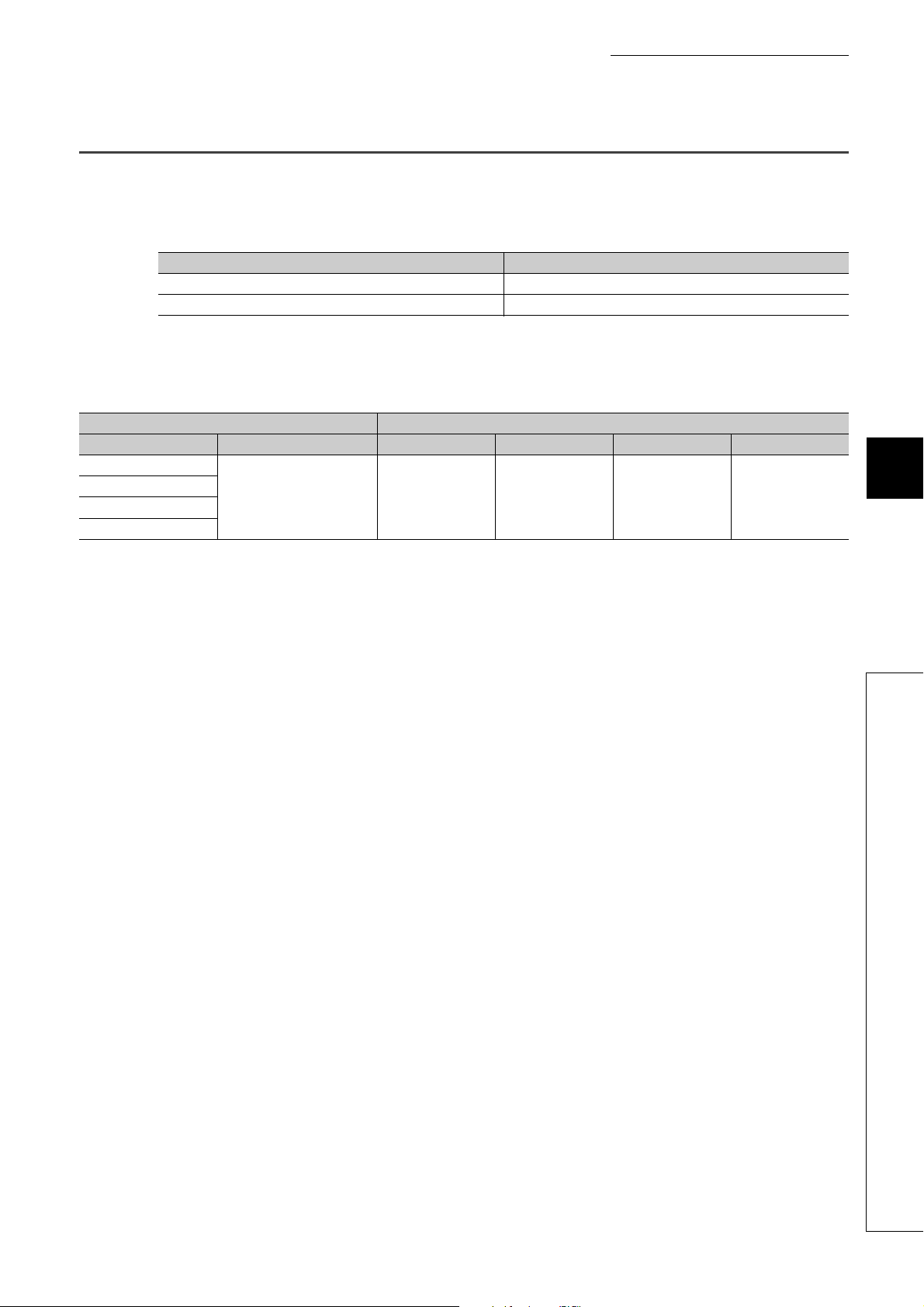
CHAPTER 6 INSTALLATION AND WIRING
6.6 Wiring of Terminal Block and External Devices
(1) Tightening torque
Tighten the terminal block screws within the following specified torque range.
Tightening the screws too much may damage the module case.
Screw type Tightening torque range
Terminal screw (M3) 0.43 to 0.57N⋅m
Terminal block mounting screw (M3.5) 0.68 to 0.92N⋅m
The following table shows applicable solderless terminals to be connected to the terminal block. For wiring, use
the wire and tightening torque as specified in the table below. Use UL-listed solderless terminals, and for
processing, use the tool recommended by their manufacturers. Note that a solderless terminal with an insulation
sleeve cannot be used.
Solderless terminal Wire
Model Applicable tightening torque Diameter Ty pe Material Temperature rating
R1.25-3
V2-MS3
RAP2-3SL
TGV2-3N
0.43 to 0.57N⋅m 22 to 14 AWG Stranded Copper 75 or higher
6
6.6 Wiring of Terminal Block and External Devices
63
Page 66
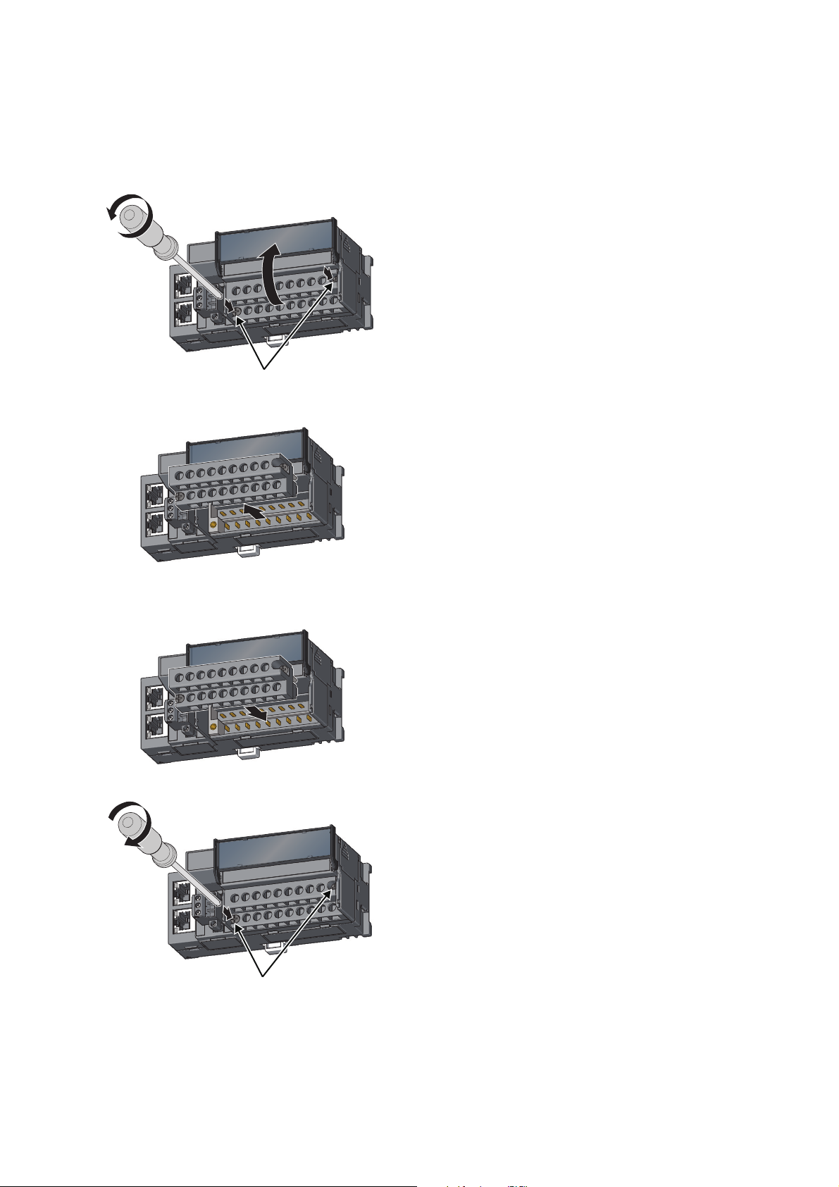
(2) Removing and installing the terminal block
Terminal block
mounting screw
Terminal block
mounting screw
(a) Removal procedure
1. Open the terminal block cover and loosen the
terminal block mounting screws (two points).
2. Loosening the terminal block mounting screws (two
points) allows the two-piece terminal block to lift
and be removed.
(b) Installation procedure
1. Open the terminal block cover to install the two-
piece terminal block.
2. Tighten the terminal block mounting screws.
64
Page 67
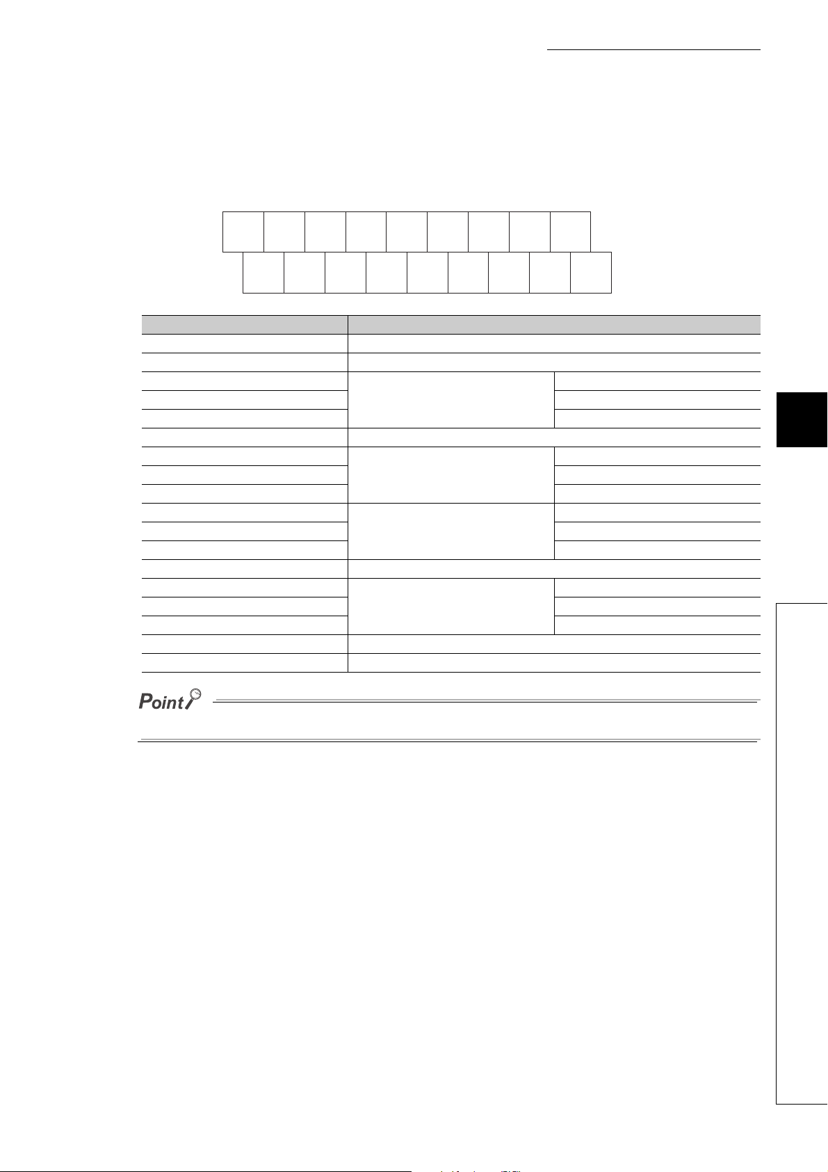
(3) Wiring of the terminal block and external devices
AGNC
CH1V+CH1I+CH2V+CH2I+CH3
COM
SLD
CH4
COM
FG1NC
CH4
I+
CH4
V+
CH3
I+
CH3
V+
CH2
COM
CH1
COM
SLD
1 3 5 7 9 11 13 15 17
246 81012141618
(a) Signal name
The following shows signal names of the terminal block.
Pin number Signal name
1NC
2NC
3
4 COM
5 I+
6SLD
7
8 COM
9 I+
10
11 COM
12 I+
13 SLD
14
15 COM
16 I+
17 AG
18 FG1
CH1
CH2
CH3
CH4
CHAPTER 6 INSTALLATION AND WIRING
V+
6
V+
V+
V+
6.6 Wiring of Terminal Block and External Devices
Do not wire the NC terminals. Incorrect wiring may cause failure or malfunction of the module.
65
Page 68
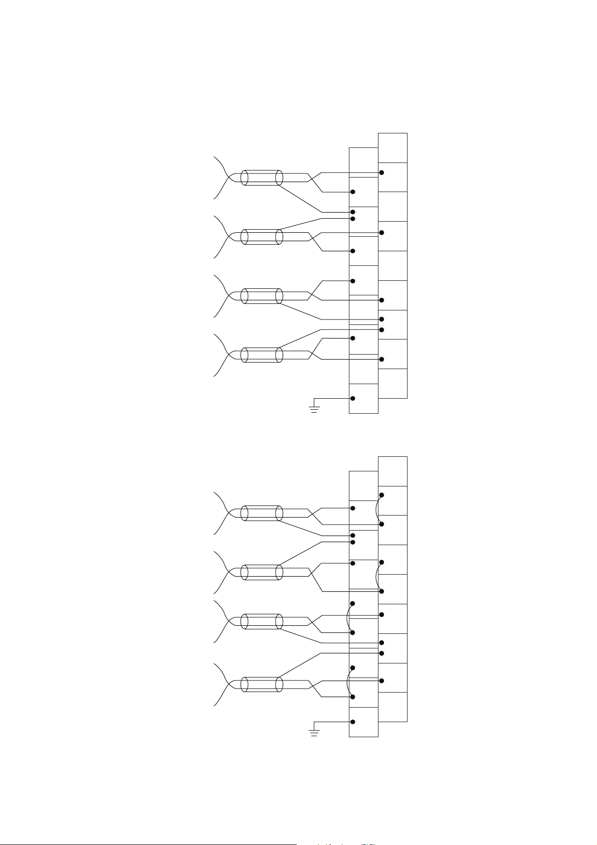
(b) Wiring to the terminal block
AG
NC
CH1
V+
CH1
I+
CH2
V+
CH2
I+
CH3
COM
SLD
CH4
COM
FG1
NC
CH4
I+
CH4
V+
CH3
I+
CH3
V+
CH2
COM
SLD
CH1
CH2
CH3
CH4
CH1
COM
AG
NC
CH1
V+
CH1
I+
CH2
V+
CH2
I+
CH3
COM
SLD
CH4
COM
FG1
NC
CH4
I+
CH4
V+
CH3
I+
CH3
V+
CH2
COM
SLD
CH1
CH2
CH3
CH4
CH1
COM
The following shows wiring to the terminal block.
• For voltage input
66
• For current input
Page 69
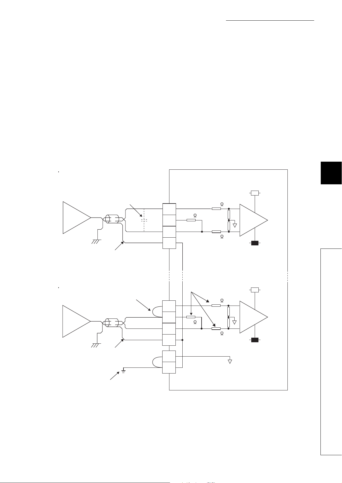
CHAPTER 6 INSTALLATION AND WIRING
(c) Precautions for external wiring
To obtain the maximum performance from the functions of the A/D converter module and improve the system
reliability, an external wiring with high durability against noise is required. Precautions for external wiring are as
follows:
• Use separate cables for the AC control circuit and the external input signals of the A/D converter module to
avoid the influence of the AC side surges or induction.
• Do not install cables together with the main circuit lines, high voltage lines, or power cables for equipment
other than the programmable controller. Noise, surges, or induction may affect the system.
• Ground the shielded wires or shielded cables at one point on the programmable controller side. However,
depending on the external noise conditions, it may be better to ground them externally.
• For the voltage input, do not exceed a range of ±15V. Doing so can cause breakdown of the elements.
• For the current input, do not exceed a range of ±30mA. Doing so can cause breakdown of the elements.
(d) External wiring
The following figure shows the external wiring.
For voltage input
Signal source: -10 to 10V
1
*
Shield
For current input
Signal source: 0 to 20mA
1
*
6
*4
*3
CH1
COM
CH4
COM
V+
I+
SLD
V+
I+
SLD
250
250
500k
500k
6.6 Wiring of Terminal Block and External Devices
2
*
500k
500k
Shield
5
*
*1 For the cable, use the 2-core shielded twisted pair cable.
*2 This indicates the input resistance of the A/D converter module.
*3 For the current input, always connect the terminals (V+) and (I+).
*4 If noise or ripple is generated in the external wiring, connect a capacitor of approximately 0.1 to 0.47μF (product with a
voltage-resistance of 25V or higher) between the V+ and COM terminals.
*5 Ground the FG1 terminal without fail. If there is much noise, it may be better to ground the AG terminal as well.
If the grounding status of the AG terminal is changed after the offset/gain values are set, set the values again.
AG
FG1
67
Page 70

(e) Wiring method
1. Loosen the terminal screw. A round solderless
Employs a captive
screw
Round solderless
terminal
● Avoid contact of the terminal and the screw with oil. Failure to do so may damage the screw.
● The number of the inserted applicable solderless terminals must be two or less.
When inserting two applicable solderless terminals, insert them back-to-back. Otherwise the screw cannot be tightened,
possibly causing damage to it.
● Tighten the terminal screw with an applicable screwdriver. Tightening with an inapplicable screwdriver may damage the
screw.
terminal can be connected as it is.
68
Page 71
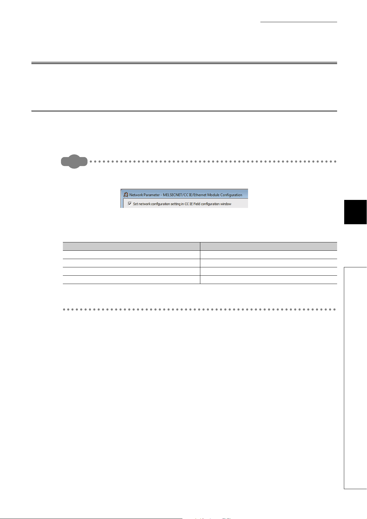
CHAPTER 7 VARIOUS SETTINGS
Remark
CHAPTER 7 VARIOUS SETTINGS
This chapter describes how to set up various settings of the A/D converter module.
7.1 Parameter Settings
Set the parameter of this module with the network parameter written to the CPU module of the master station. For the
setting procedure of the master station, refer to the following:
User's manual for the master/local module used
● Place a checkmark in the "Set the network configuration settings in CC IE Field configuration window" box on the
"MELSECNET/CC IE/Ethernet Module Configuration" window in advance.
● To select the main A/D converter module in the CC IE Field Configuration window, select "NZ2GF2B-60AD4" from the
"Module List" window.
● To select an extension module in the "CC IE Field Configuration" window, select the following models from the "Module
List" window.
Extension module type Name
Extension Digital Input Module NZ2EX-16 (DI)
Extension Digital Output Module NZ2EX-16 (DO)
Extension A/D Converter Module NZ2EX2B-60AD4
Extension D/A Converter Module NZ2EX2B-60DA4
● Setting fewer points of the remote I/O signal or remote register than actual points that the main A/D converter module or
the extension module possesses does not cause an error. In this case, data of all the set points are subject to cyclic
transmission in order.
7
7.1 Parameter Settings
69
Page 72
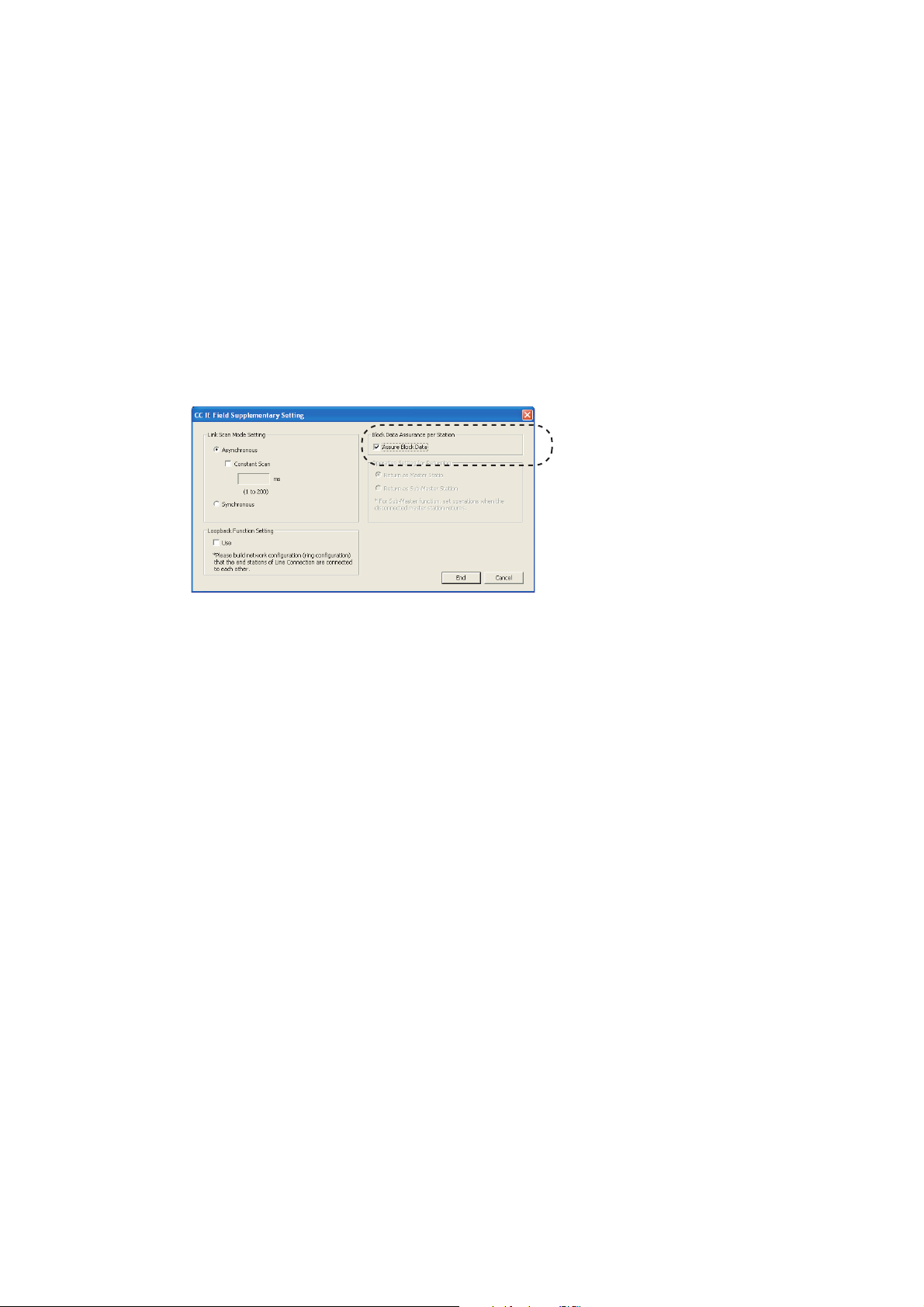
(1) Precautions
Do not uncheck the box.
(a) Before parameter settings
For the precautions before parameter settings, refer to the following.
GX Works3 Operating Manual
GX Works2 Version 1 Operating Manual (Common)
(b) Parameter settings
• When using the A/D converter module, always enable the block data assurance per station. When it is
disabled, correct operation of the A/D converter module cannot be guaranteed. For details on the block
data assurance per station, refer to the following: User's manual for the master/local module used.
• Do not set the parameters using the CCPASET instruction in the master station. Executing the CCPASET
instruction results in the module operating with block data assurance per station deactivated, where proper
performance as the A/D converter module cannot be guaranteed. (The CCPASET instruction is intended
to configure parameters for a master/local module. For details on the CCPASET instruction, refer to the
following: User's manual for the master/local module used.)
• When using an extension module, be sure to write the module parameters ( Page 71, Section 7.1 (2)).
If the parameters of the extension module has not been written, the error code (1F30H) is stored in Latest
error code (RWr0), Error flag (RXA) turns on, and the ERR. LED lights up.
70
Page 73
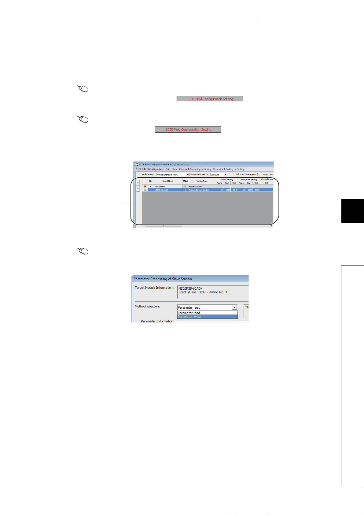
CHAPTER 7 VARIOUS SETTINGS
Station list
(2) Setting procedure
1. Open the "CC IE Field Configuration" window.
• For the master/local module QJ71GF11-T2
Project window [Parameter] [Network Parameter]
[Ethernet/CC IE/MELSECNET] button
• For the master/local module LJ71GF11-T2
Project window [Parameter] [Network Parameter]
[Ethernet/CC IE Field] button
2. On the "CC IE Field Configuration" window, from "List of stations", select the main A/D converter
module.
3. Open the "Parameter Processing of Slave Station" window.
[CC IE Field Configuration] [Online] [Parameter Processing of Slave Station]
4. Set "Method selection" to "Parameter write".
7
7.1 Parameter Settings
71
Page 74

5. Double-click the item to be changed, and enter the setting value.
Select an item from the pull-down list.
Enter a value in the text box.
The checkbox cannot be unchecked.
The list cannot be collapsed.
• Items to be selected from a pull-down list
Double-click the item to be set, and from the pull-down list that appears, select the desired item.
• Items to be entered via text box
Double-click the item to be set, and enter the desired value.
• Station parameter
Setting item Reference
Mode switch Page 86, Section 8.2
Conversion speed setting Page 89, Section 8.5
Trigger conversion signal assignment
Input signal error detection signal assignment
External signal assignment function
Cyclic data update watch time setting
Extension I/O setting
Alert output signal assignment
Error flag assignment
Warning flag assignment
Input response time setting
Digital output HOLD/CLEAR setting
Page 146, Section 8.18.1 (2)
Page 145, Section 8.18.1
• Basic module parameter
Setting item Reference
CH1 A/D conversion enable/disable setting
A/D conversion enable/disable setting
Range setting
CH2 A/D conversion enable/disable setting
CH3 A/D conversion enable/disable setting
CH4 A/D conversion enable/disable setting
CH1 Range setting
CH2 Range setting
CH3 Range setting
CH4 Range setting
Page 89, Section 8.4
Page 99, Section 8.7
72
Page 75

Averaging process setting
Input signal error detection function
Alert output function
Digital clipping function
Scaling function
CHAPTER 7 VARIOUS SETTINGS
Setting item Reference
CH1 Averaging process setting
CH1 Time average/Count average/Moving average
CH2 Averaging process setting
CH2 Time average/Count average/Moving average
CH3 Averaging process setting
CH3 Time average/Count average/Moving average
CH4 Averaging process setting
CH4 Time average/Count average/Moving average
CH1 Input signal error detection setting
CH2 Input signal error detection setting
CH3 Input signal error detection setting
CH4 Input signal error detection setting
CH1 Alert output setting
CH1 Process alarm upper upper limit value
CH1 Process alarm upper lower limit value
CH1 Process alarm lower upper limit value
CH1 Process alarm lower lower limit value
CH2 Alert output setting
CH2 Process alarm upper upper limit value
CH2 Process alarm upper lower limit value
CH2 Process alarm lower upper limit value
CH2 Process alarm lower lower limit value
CH3 Alert output setting
CH3 Process alarm upper upper limit value
CH3 Process alarm upper lower limit value
CH3 Process alarm lower upper limit value
CH3 Process alarm lower lower limit value
CH4 Alert output setting
CH4 Process alarm upper upper limit value
CH4 Process alarm upper lower limit value
CH4 Process alarm lower upper limit value
CH4 Process alarm lower lower limit value
CH1 Digital clipping enable/disable setting
CH2 Digital clipping enable/disable setting
CH3 Digital clipping enable/disable setting
CH4 Digital clipping enable/disable setting
CH1 Scaling enable/disable setting
CH1 Scaling upper limit value
CH1 Scaling lower limit value
CH2 Scaling enable/disable setting
CH2 Scaling upper limit value
CH2 Scaling lower limit value
CH3 Scaling enable/disable setting
CH3 Scaling upper limit value
CH3 Scaling lower limit value
CH4 Scaling enable/disable setting
CH4 Scaling upper limit value
CH4 Scaling lower limit value
Page 95, Section 8.6
Page 101, Section 8.9
Page 105, Section 8.10
Page 117, Section 8.13
Page 108, Section 8.11
7
7.1 Parameter Settings
73
Page 76

• Ext. module 1_Module parameter
Ext. module 1_A/D conversion enable/disable setting
Ext. module 1_Range setting
Ext. module 1_Average processing setting
Ext. module 1_Input signal error detection function
Ext. module 1_Alert output function
Ext. module 1_Digital clipping function
Setting item Reference
Ext. module 1_CH1 A/D conversion enable/disable setting
Ext. module 1_CH2 A/D conversion enable/disable setting
Ext. module 1_CH3 A/D conversion enable/disable setting
Ext. module 1_CH4 A/D conversion enable/disable setting
Ext. module 1_CH1 Range setting
Ext. module 1_CH2 Range setting
Ext. module 1_CH3 Range setting
Ext. module 1_CH4 Range setting
Ext. module 1_CH1 Averaging process setting
Ext. module 1_CH1 Time average/Count average/Moving
average
Ext. module 1_CH2 Averaging process setting
Ext. module 1_CH2 Time average/Count average/Moving
average
Ext. module 1_CH3 Averaging process setting
Ext. module 1_CH3 Time average/Count average/Moving
average
Ext. module 1_CH4 Averaging process setting
Ext. module 1_CH4 Time average/Count average/Moving
average
Ext. module 1_CH1 Input signal error detection function setting
Ext. module 1_CH2 Input signal error detection function setting
Ext. module 1_CH3 Input signal error detection function setting
Ext. module 1_CH4 Input signal error detection function setting
Ext. module 1_CH1 Alert output setting
Ext. module 1_CH1 Process alarm upper upper limit value
Ext. module 1_CH1 Process alarm upper lower limit value
Ext. module 1_CH1 Process alarm lower upper limit value
Ext. module 1_CH1 Process alarm lower lower limit value
Ext. module 1_CH2 Alert output setting
Ext. module 1_CH2 Process alarm upper upper limit value
Ext. module 1_CH2 Process alarm upper lower limit value
Ext. module 1_CH2 Process alarm lower upper limit value
Ext. module 1_CH2 Process alarm lower lower limit value
Ext. module 1_CH3 Alert output setting
Ext. module 1_CH3 Process alarm upper upper limit value
Ext. module 1_CH3 Process alarm upper lower limit value
Ext. module 1_CH3 Process alarm lower upper limit value
Ext. module 1_CH3 Process alarm lower lower limit value
Ext. module 1_CH4 Alert output setting
Ext. module 1_CH4 Process alarm upper upper limit value
Ext. module 1_CH4 Process alarm upper lower limit value
Ext. module 1_CH4 Process alarm lower upper limit value
Ext. module 1_CH4 Process alarm lower lower limit value
Ext. module 1_CH1 Digital clipping enable/disable setting
Ext. module 1_CH2 Digital clipping enable/disable setting
Ext. module 1_CH3 Digital clipping enable/disable setting
Ext. module 1_CH4 Digital clipping enable/disable setting
Page 89, Section 8.4
Page 99, Section 8.7
Page 95, Section 8.6
Page 101, Section 8.9
Page 105, Section 8.10
Page 117, Section 8.13
74
Page 77

Ext. module 1_Scaling function
6. Click button to open the following window.
CHAPTER 7 VARIOUS SETTINGS
Setting item Reference
Ext. module 1_CH1 Scaling enable/disable setting
Ext. module 1_CH1 Scaling upper limit value
Ext. module 1_CH1 Scaling lower limit value
Ext. module 1_CH2 Scaling enable/disable setting
Ext. module 1_CH2 Scaling upper limit value
Ext. module 1_CH2 Scaling lower limit value
Ext. module 1_CH3 Scaling enable/disable setting
Ext. module 1_CH3 Scaling upper limit value
Ext. module 1_CH3 Scaling lower limit value
Ext. module 1_CH4 Scaling enable/disable setting
Ext. module 1_CH4 Scaling upper limit value
Ext. module 1_CH4 Scaling lower limit value
Page 108, Section 8.11
7. Click button.
8. The parameters are written to the A/D converter module.
● When using an extension module, also set the parameters of the extension module.
For the parameters of the extension module, refer to the following:
Manual of the extension module used
● Set all the items for the parameter. If any blank exists, the parameters cannot be written to the A/D converter module.
● To read the parameter from the A/D converter module, set "Method selection" to "Parameter read" and click
button.
● The parameters are checked when they are written to the A/D converter module. If the following message is displayed
during the writing, take corrective action for the error code in < >. For details on the error codes, refer to the list of error
codes ( Page 172, Section 11.2) and the user’s manual for the master/local module used.
7
7.1 Parameter Settings
75
Page 78

7.2 How to Change the Parameters
This section describes the procedures to change the parameters.
The precautions to take when changing the parameters are the same as the following:
• Precautions ( Page 70, Section 7.1 (1))
7.2.1 Changing the network configuration
To change the network configuration reusing the already created project, set the parameters in the following steps:
1. Turn off the module power supply from on.
2. Connect the modules again according to the desired network configuration.
3. Turn on the module power supply from off.
4. Open the "CC IE Field Configuration" window.
• For the master/local module QJ71GF11-T2
Project window [Parameter] [Network Parameter]
[Ethernet/CC IE/MELSECNET] button
• For the master/local module LJ71GF11-T2
Project window [Parameter] [Network Parameter]
[Ethernet/CC IE Field] button
5. Set up the slave station with drag and drop, and enter the station number for the slave station.
Change values as necessary.
76
Page 79

CHAPTER 7 VARIOUS SETTINGS
Station list
6. On the "CC IE Field Configuration" window, from "List of stations", select the main A/D converter
module.
7. Open the "Parameter Processing of Slave Station" window.
[CC IE Field Configuration] [Online] [Parameter Processing of Slave Station]
8. Set "Method selection" to "Parameter read".
9. Click button to open the following window.
10. Click button.
11. The parameters are read from the A/D converter module.
7
7.2 How to Change the Parameters
77
Page 80
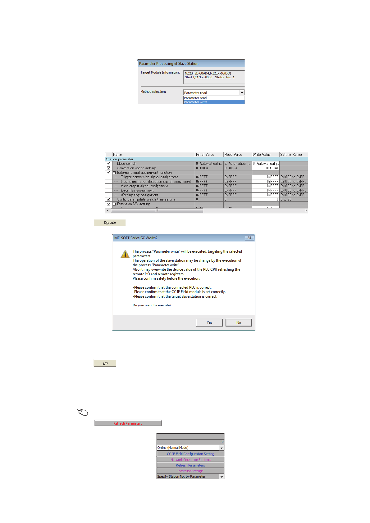
12. Set "Method selection" to "Parameter write".
13. Set "Write Value". Follow the next steps to set the value:
• Click the title cell of "Read Value" to select all the items and copy them.
• Click the title cell of "Write Value" to select all the items and paste the copy.
• Select the items to be changed, and set new values.
14. Click button to open the following window.
78
15. Click button.
16. The parameters are written to the A/D converter module.
Setting up the module parameters of the slave station is now complete.
17. Close the "CC IE Field Configuration" window.
[CC IE Field Configuration] [Close with Reflecting the Setting]
18. Click button to open the refresh parameter setting window.
Page 81
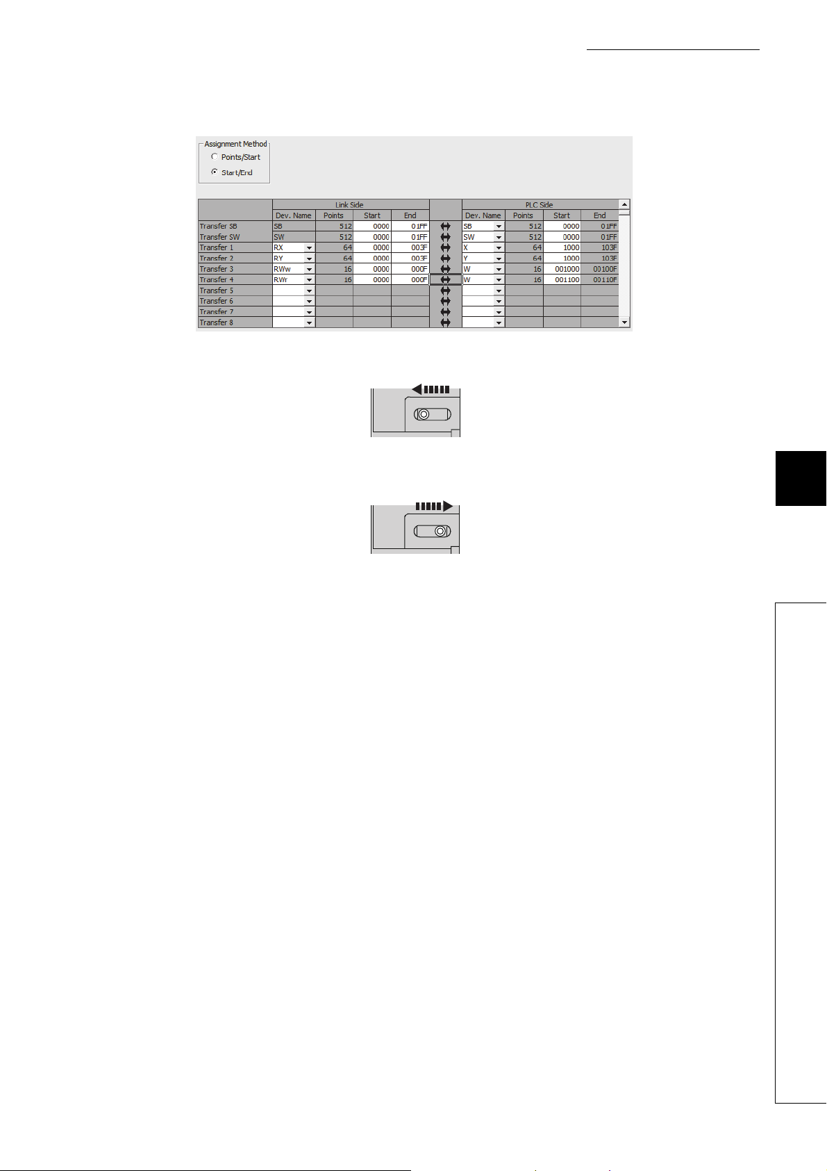
CHAPTER 7 VARIOUS SETTINGS
RESET
RUN
19. Set up the refresh parameters. Change values as necessary.
20. Write the set parameters to the CPU module of the master station, and reset the CPU module.
21. Put the CPU module of the master station into RUN.
Setting up the network configuration is now complete.
7
7.2 How to Change the Parameters
79
Page 82
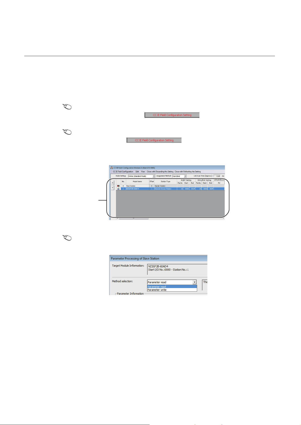
7.2.2 Changing the parameters without changing the network
configuration
To change only the module parameters of the already set-up slave station without changing the network configuration,
take the following steps:
1. Open the "CC IE Field Configuration" window.
• For the master/local module QJ71GF11-T2
Project window [Parameter] [Network Parameter]
[Ethernet/CC IE/MELSECNET] button
• For the master/local module LJ71GF11-T2
Project window [Parameter] [Network Parameter]
[Ethernet/CC IE Field] button
2. On the "CC IE Field Configuration" window, from "List of stations", select the A/D converter
module.
Station list
3. Open the "Parameter Processing of Slave Station" window.
[CC IE Field Configuration] [Online] [Parameter Processing of Slave Station]
4. Set "Method selection" to "Parameter read".
80
Page 83
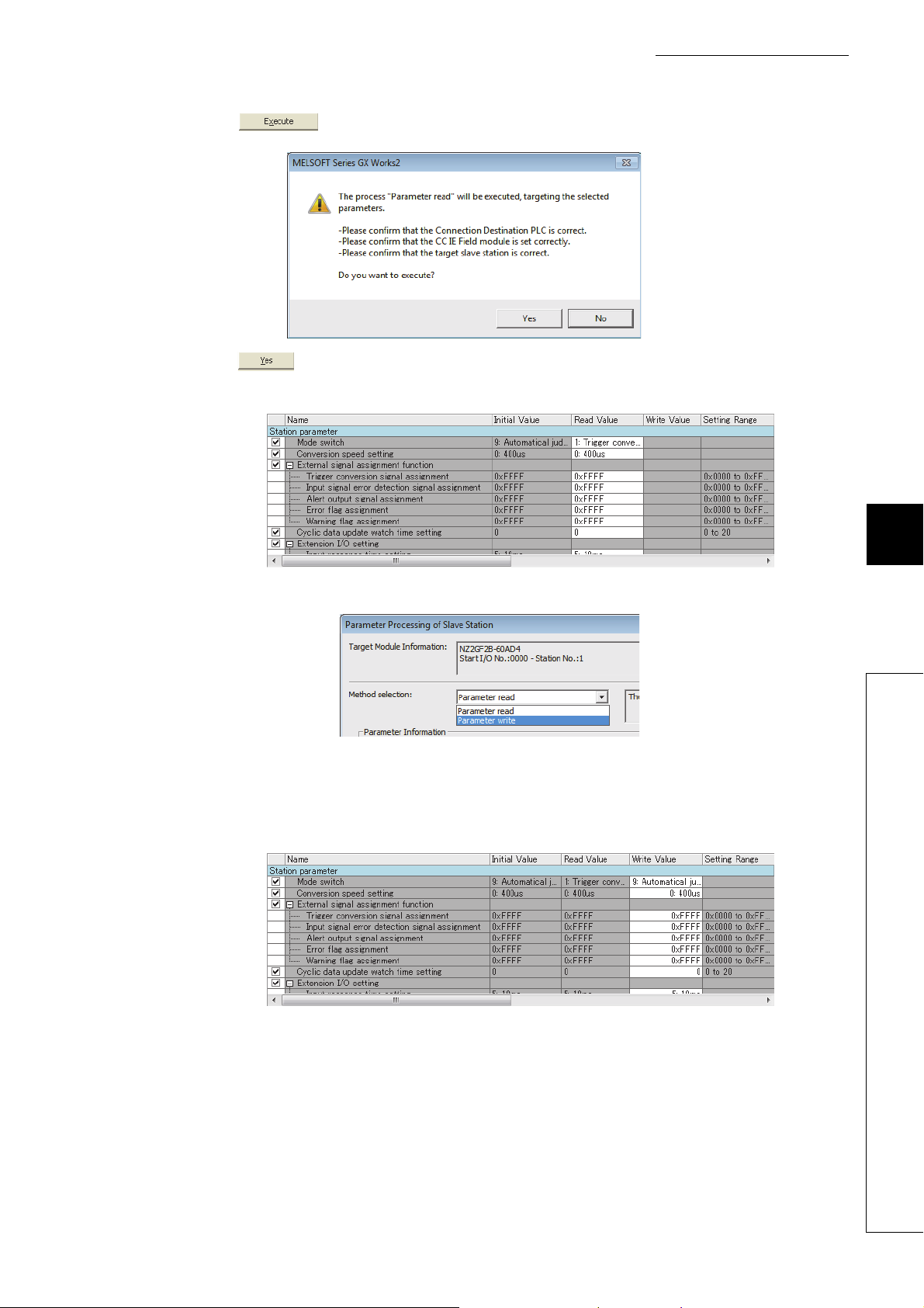
5. Click button to open the following window.
6. Click button.
7. The parameters are read from the A/D converter module.
CHAPTER 7 VARIOUS SETTINGS
8. Set "Method selection" to "Parameter write".
9. Set "Write Value". Follow the next steps to set the value:
• Click the title cell of "Read Value" to select all the items and copy them.
• Click the title cell of "Write Value" to select all the items and paste the copy.
• Select the items to be changed, and set new values.
7
7.2 How to Change the Parameters
81
Page 84
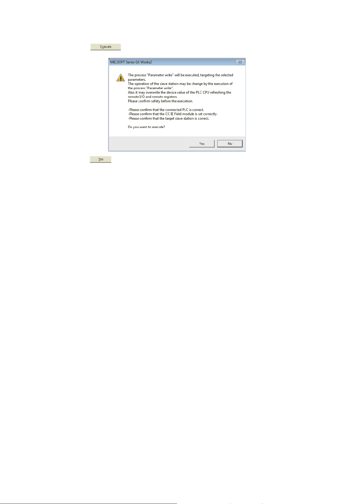
10. Click button to open the following window.
11. Click button.
12. The parameters are written to the A/D converter module.
Setting the module parameters of the slave station is complete.
82
Page 85
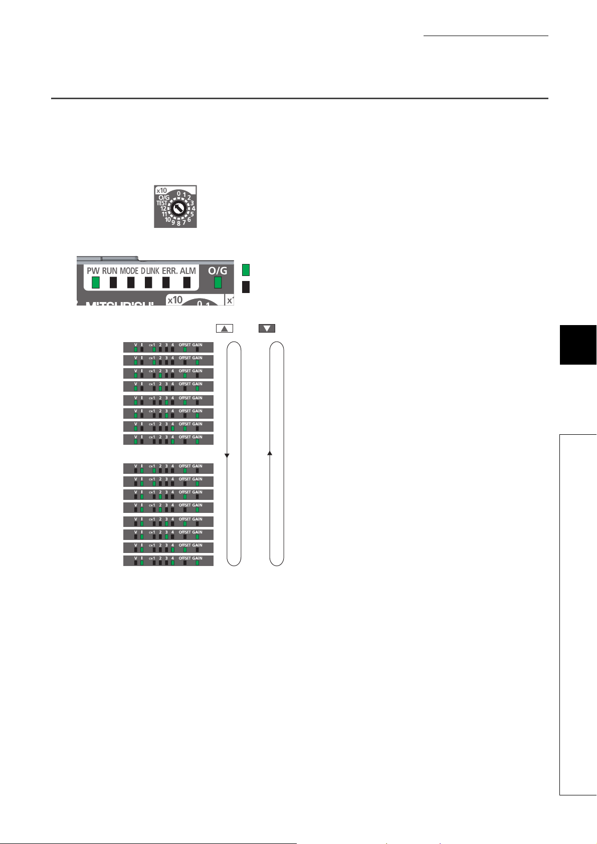
CHAPTER 7 VARIOUS SETTINGS
: OFF
: ON
7.3 Offset/Gain Setting
If the user range is necessary, set up the offset/gain setting by following the instructions as illustrated below.
Note that using the factory default range does not require the offset/gain setting.
1. Turn off the module power supply.
2. Set x10 of the station number setting switch to O/G.
3. Turn on the module power supply and check that
the LEDs are in the following state:
RUN LED: Off
O/G LED: On
[User range setting 1 (-10 to 10V)]
CH1: Offset
CH1: Gain
CH2: Offset
CH2: Gain
CH3: Offset
CH3: Gain
CH4: Offset
CH4: Gain
[User range setting 2 (-5 to 5V, -20 to 20mA)]
CH1: Offset
CH1: Gain
CH2: Offset
CH2: Gain
CH3: Offset
CH3: Gain
CH4: Offset
CH4: Gain
button button
4. Select the setting target using SET/SEL button.
7
7.3 Offset/Gain Setting
5. Apply the offset value or gain value to the selected
channel for one second or more.
83
Page 86
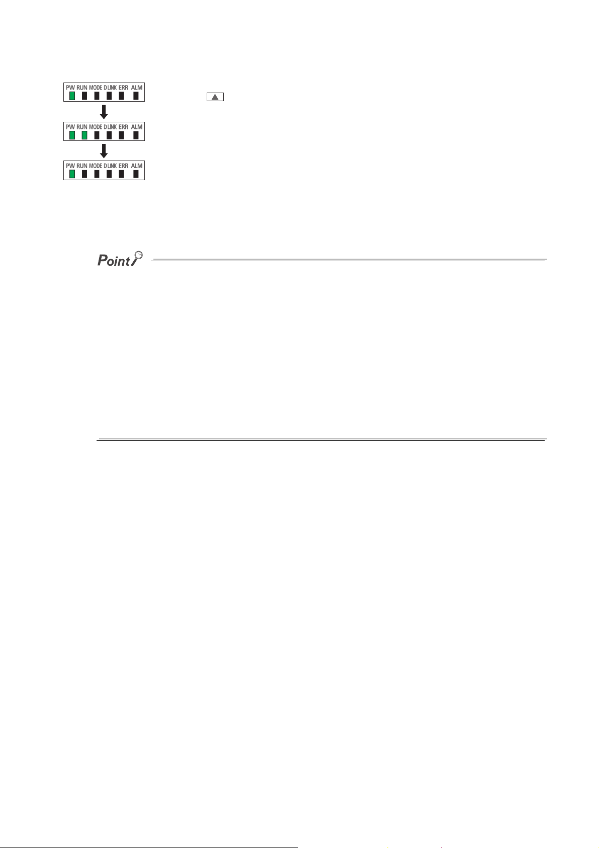
6. Keep pressing button until the RUN LED lights
Data is being written.
The write is complete.
Keep pressing button.
up.
Once the RUN LED lights up, release button. While
the RUN LED lights up, the offset value or gain value is
being written to the non-volatile memory.
After the writing, the RUN LED lights out.
After checking that the RUN LED lights out, go to the
next step.
7. To set up another channel, go back to step 4.
8. After setting all the channels to be used, turn off the
module power supply.
● Set up the offset value and the gain value under actual use conditions.
Connection to the CC-Link IE Field Network is not necessary.
● Set up the offset/gain setting in the range satisfying the following condition. If the range is exceeded, the maximum
resolution and accuracy may not fall within the range described in the performance specifications.
• I/O Conversion Characteristics of A/D Conversion ( Page 229, Appendix 4)
● Set values are held and available even after turning off the module power supply because a offset value and a gain value
are written into the non-volatile memory in the main A/D converter module.
● Set up the offset/gain setting so that the offset value is smaller than the gain value.
With Range setting (address: 0103H) set to User range setting 1 or User range setting 2, the main A/D converter module
performs a check on the offset/gain set values when Initial data setting request flag (RY9) is turned on from off. For
invalid condition (offset value ≥ gain value), this check results in the error code (040H) being stored into Latest error
code (RWr0), Error flag (RXA) turning on, and the ERR. LED lighting up.
● The extension A/D converter module does not support user range. Therefore, the offset/gain setting cannot be set up for
the extension A/D converter module.
84
Page 87
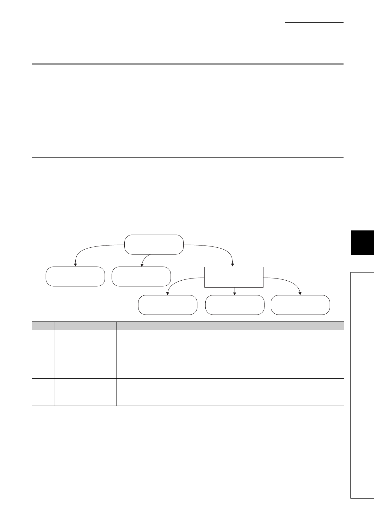
CHAPTER 8 FUNCTIONS
c)
b)
a)
Unit test modeOffset/gain setting mode
Trigger conversion mode
Power-on
(Drive mode switch)
Normal mode
Synchronous
communication mode
CHAPTER 8 FUNCTIONS
This chapter describes the details of the functions available in the A/D converter module, and the setting procedures
for those functions.
For details on remote I/O signals, remote registers, and remote buffer memory, refer to the following:
• Details of Remote I/O Signals ( Page 189, Appendix 1)
• Details of Remote Registers ( Page 201, Appendix 2)
• Details of Remote Buffer Memory ( Page 205, Appendix 3)
8.1 Mode Shift at Power-On
At power-on, the main A/D converter module enters any of the following modes:
• Offset/gain setting mode
• Unit test mode
• Normal mode
• Trigger conversion mode
• Synchronous communication mode
The conditions of shift to these modes are shown below:
Mark Mode Condition
If x10 of the station number setting switch is set to O/G, the mode shifts to offset/gain setting mode.
a) Offset/gain setting mode
b) Unit test mode
c) (Drive mode switch)
For details, refer to the following:
• Offset/Gain Setting ( Page 83, Section 7.3)
If x10 of the station number setting switch is set to TEST and x1 of the switch is set to 0, the mode shifts to the unit
test mode.
For details, refer to the following:
• Unit Test ( Page 185, Section 11.5)
With the station number setting switch set to 1 to 120, the module enters each drive mode according to the setting
of Mode switch (address: 0000H).
For details, refer to the following:
• Drive Mode Switch ( Page 86, Section 8.2)
8
8.1 Mode Shift at Power-On
85
Page 88
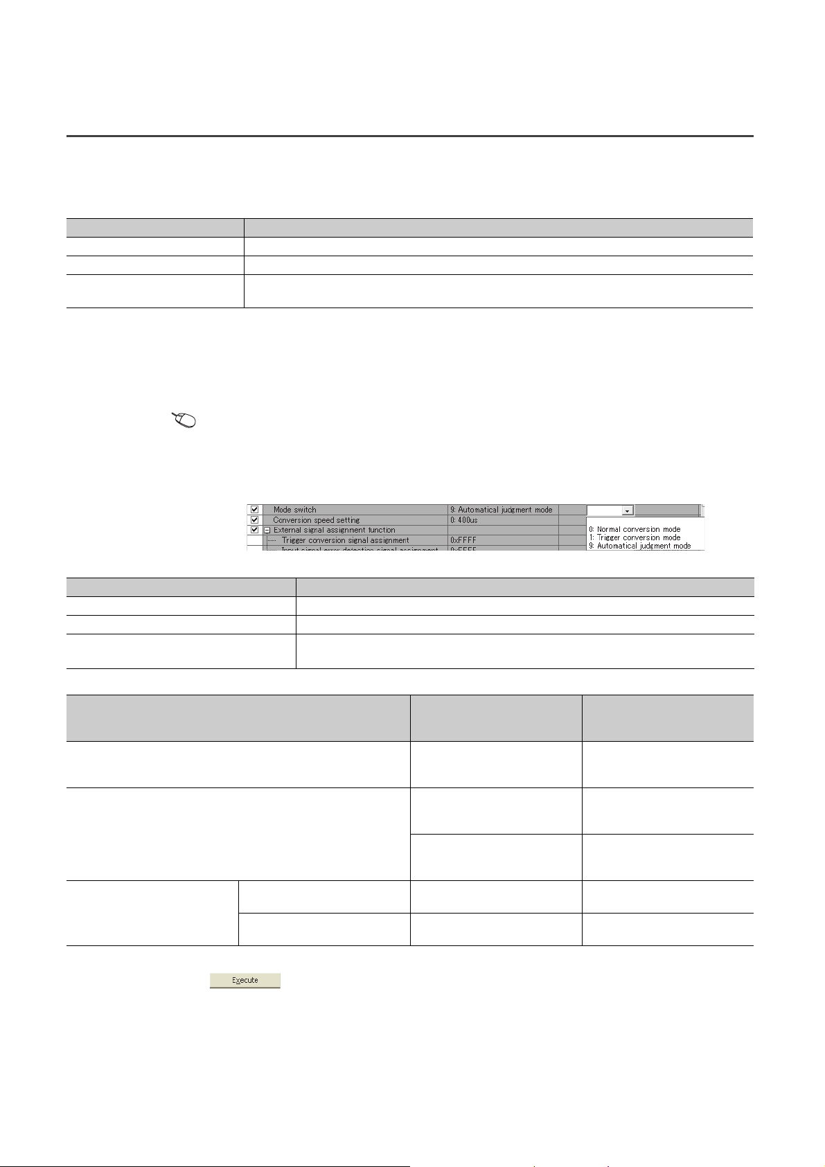
8.2 Drive Mode Switch
The A/D converter module operates in the following modes: normal mode, trigger conversion mode, and synchronous
communication mode.
The following table lists the types of drive mode and their operation.
Type of drive mode Operation
Normal mode A/D conversion is performed based on the internal clock of the main A/D converter module.
Trigger conversion mode A/D conversion is performed at the time of turning on Trigger conversion request (RY19, RY29) from off.
Synchronous communication mode
The drive mode can be selected by setting Mode switch (address: 0000H).
(1) Setting procedure
1. Set "Method selection" to "Parameter write".
"CC IE Field Configuration" window Select a main A/D converter module from "List of stations"
[CC IE Field Configuration] [Online] [Parameter Processing of Slave Station]
2. In "Station parameter", set "Mode switch" to either "0: Normal conversion mode", "1: Trigger
conversion mode", or "9: Automatical judgment mode".
A/D conversion is performed with a synchronization period of the master station that supports the CC-Link IE Field
Network synchronous communication function.
The following table lists the setting value of "Mode switch" and the drive mode.
Setting value of "Mode switch" Drive mode
"0: Normal conversion mode" The A/D converter module operates in normal mode.
"1: Trigger conversion mode" The A/D converter module operates in trigger conversion mode.
"9: Automatical judgment mode"
*1 The drive mode varies depending on the module of the master station as shown below.
Master station
Master/local module
(CC-Link IE Field Network synchronous communication function not
supported)
Master/local module
(CC-Link IE Field Network synchronous communication function supported)
First five digits of the serial number
Simple motion module
*2 For how to set the master station, refer to the MELSEC iQ-R Inter-Module Synchronization Function Reference Manual.
are 15091 or earlier.
First five digits of the serial number
are 15092 or later.
The drive mode is automatically set according to the type of the module that operates as the master
station of the A/D converter module.
*1
Setting of the master station
Normal mode
Setting the CC-Link IE Field Network
synchronous communication function
to be disabled
Setting the CC-Link IE Field Network
synchronous communication function
to be enabled
Normal mode
Synchronous communication mode
*2
Drive mode when "Mode switch" is
set to "9: Automatical judgment
mode"
Normal mode
Synchronous communication mode
86
3. Click button to write the parameters to the A/D converter module.
Page 89
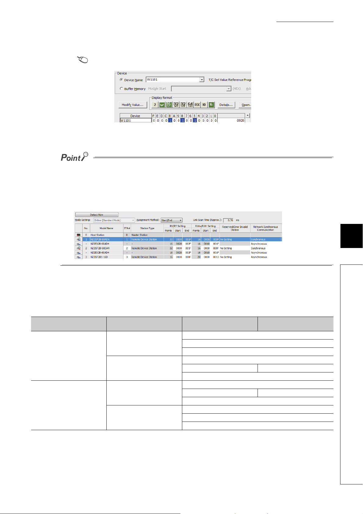
CHAPTER 8 FUNCTIONS
4. Check that "0920H" is stored in Latest warning code (RWr1).
[Online] [Monitor] [Device/Buffer Memory Batch]
5. The A/D converter module starts operating in the set drive mode by turning off and on the module
power supply or performing remote reset.
● For normal conversion mode operation of the A/D converter module connected to a master station that supports the CCLink IE Field Network synchronous communication function, set to "0: Normal conversion mode".
● In the MELSEC iQ-R series master station, setting each slave station to Synchronous or Asynchronous allows their
operation (synchronous communication mode or normal mode) to be managed and configured at a time by the master
station. Note, however, that settings for the extension modules have no effect. Their operation follows the settings of the
main module connected.
(2) Drive mode of extension modules
When an extension analog module is connected to a main analog module, the extension analog module operates
in the drive mode corresponding to that of the main analog module.
The following table lists the details.
Main analog module Extension analog module Drive mode of main analog module
Normal mode
Extension A/D converter module
Main A/D converter module
Extension D/A converter module
Extension A/D converter module
Main D/A converter module
Extension D/A converter module
Trigger conversion mode
Synchronous communication mode
Normal mode
Trigger conversion mode Trigger output mode
Synchronous communication mode
Normal mode
Trigger output mode Trigger conversion mode
Synchronous communication mode
Normal mode
Trigger output mode
Synchronous communication mode
8
8.2 Drive Mode Switch
Drive mode of extension analog
module
87
Page 90

8.3 Each Function in the Sequence
CH Maximum value CH Minimum value
Alert output function
Difference conversion
function
Shift function
Scaling function
Digital clipping function
Input signal error detection function
Analog input
(CH1 to CH4)
Averaging processing
Maximum value/minimum value hold function
CC-Link IE Field Network
synchronous communication
function
Trigger conversion
function
Mode
switch
Normal mode
Trigger conversion
mode
Synchronous
communication mode
CH
Digital
operation value
An analog input value and digital operation value are processed by the functions in the order shown below. If multiple
functions are enabled, the output of the first-processed function is used as the input of the next function.
(1) Digital operation value
Digital values after sampling processing or averaging processing have been performed are called digital output
values.
The values obtained by operating the digital output value using the digital clipping function, scaling function, shift
function, or difference conversion function are stored.
(2) Maximum and minimum values
The maximum and minimum values of the digital operation values are stored.
88
Page 91
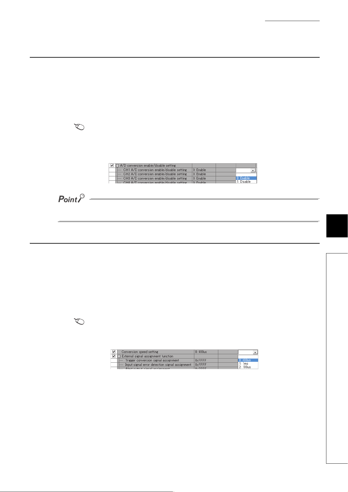
8.4 A/D Conversion Enable/Disable Function
This function allows A/D conversion to be enabled or disabled for each channel.
Disabling the A/D conversion for unused channels reduces the conversion cycles.
(1) Setting procedure
The setting procedure for the main A/D converter module is as follows:
1. Set "Method selection" to "Parameter write".
"CC IE Field Configuration" window Select a main A/D converter module from "List of stations"
[CC IE Field Configuration] [Online] [Parameter Processing of Slave Station]
2. In "Basic module parameter", set "CH A/D conversion enable/disable setting" to either "0:
Enable" or "1: Disable".
CHAPTER 8 FUNCTIONS
For the extension A/D converter module, go to "Ext. module 1_Module parameter", and make the setting of "Ext. module
1_CH A/D conversion enable/disable setting".
8.5 Conversion Speed Switch Function
Conversion speed of the main A/D converter module can be selected from the following three rates:
•100μs
•400μs
•1ms
(1) Setting procedure
1. Set "Method selection" to "Parameter write".
"CC IE Field Configuration" window Select a main A/D converter module from "List of stations"
[CC IE Field Configuration] [Online] [Parameter Processing of Slave Station]
2. In "Station parameter", from "Conversion speed setting", select the conversion speed.
8
8.4 A/D Conversion Enable/Disable Function
89
Page 92

8.5.1 Conversion speed and sampling period
CH1 CH1
Sampling period
: Period for conversion processing of one channel
Conversion
processing
Conversion
speed
Processing including
conversion processing
of other channels
Conversion
processing
Conversion speed is the rate at which an A/D converter module converts analog input values.
A sampling period is the period of conversion processing within the one channel.
A conversion period is the period of the update of a digital operation value with the A/D conversion method (sampling
processing or averaging processing) taken into account, and is equivalent to an integral multiple of the sampling
period. ( Page 95, Section 8.6)
The following figure shows the relationship between conversion speed and a sampling period.
The sampling cycle varies depending on the type of main analog module, the conversion speed, the type of extension
module, and the number of conversion enabled channels.
The following table shows the classification.
Main analog module Extension module
• Not connected
• Extension I/O module
Main A/D converter
module
Main D/A converter
module
Extension A/D converter module
Extension D/A converter module
• Not connected
• Extension I/O module
Extension A/D converter module −
Extension D/A converter module −
Conversion
speed setting
•100μs
•400μs
•1ms
100μs
400μs
1ms
•100μs
•400μs
•1ms
−
Sampling period
Conversion speed × Number of
conversion enabled channels
200μs × Number of conversion
enabled channels
500μs × Number of conversion
enabled channels
1ms × Number of conversion
enabled channels
200μs × Number of conversion
enabled channels
100μs × Number of conversion
enabled channels
200μs × Number of conversion
enabled channels
200μs × Number of conversion
enabled channels
*1
Page 91, Section 8.5.1 (1)
Page 91, Section 8.5.1 (2) (a)
Page 92, Section 8.5.1 (2) (b)
Page 92, Section 8.5.1 (2) (c)
Page 93, Section 8.5.1 (3)
*2
Page 94, Section 8.5.1 (4)
*2
Reference
*1 For a D/A converter module, this column corresponds to the conversion period.
*2 For details, refer to the following:
• CC-Link IE Field Network Digital-Analog Converter Module User's Manual
90
Page 93

CHAPTER 8 FUNCTIONS
Ex.
Ex.
100μs
CH1
100μs
CH2
100μs
CH3
100μs
CH4
100μs
CH1
100μs
CH2
100μs
CH3
100μs
CH4
Main A/D converter module
(conversion enabled
channels: CH1 to CH4)
Sampling period of the main A/D converter module
Conversion
processing
Conversion
processing
Conversion
processing
Conversion
processing
Conversion
processing
Conversion
processing
Conversion
processing
Conversion
processing
100μs
CH1
100μs 100μs
CH2
100μs 100μs
CH3
100μs 100μs
CH4
100μs
CH1 CH2 CH3 CH4
Main A/D converter module
(conversion enabled
channels: CH1 to CH4)
Extension A/D converter
module (conversion enabled
channels: CH1 to CH4)
Sampling period of the main A/D converter module
Conversion
processing
Processing
time
Conversion
processing
Processing
time
Conversion
processing
Processing
time
Conversion
processing
Processing
time
Sampling period of the extension A/D converter module
Conversion
processing
Processing
time
Conversion
processing
Processing
time
Conversion
processing
Processing
time
Conversion
processing
Processing
time
(1) When an extension module is not connected or an extension I/O module is
connected
The sampling period is given by the following:
Sampling period = Conversion speed × Number of conversion enabled channels
Assuming that the conversion speed setting is 100μs and the number of conversion enabled channels is
4
Sampling period of the main A/D converter module = 100μs × 4 = 400μs
(2) When an extension A/D converter module is connected to a main A/D
converter module
When an extension A/D converter module is connected to a main A/D converter module, processing time (100μs)
is generated between the conversion processing of each channel.
(a) With a conversion speed of 100μs
Between the conversion processing (100μs) of each channel, processing time (100μs) is generated. Therefore,
the sampling period is given by the following:
Sampling period = (Conversion speed (100μs) + Processing time (100μs)) × Number of conversion enabled
channels
Assuming that the conversion speed setting is 100μs and the number of conversion enabled channels is
4 for both the main A/D converter module and the extension A/D converter module
8
8.5 Conversion Speed Switch Function
Sampling period of the main A/D converter module = (100μs + 100μs) × 4 = 800μs
Sampling period of the extension A/D converter module = (100μs + 100μs) × 4 = 800μs
91
Page 94
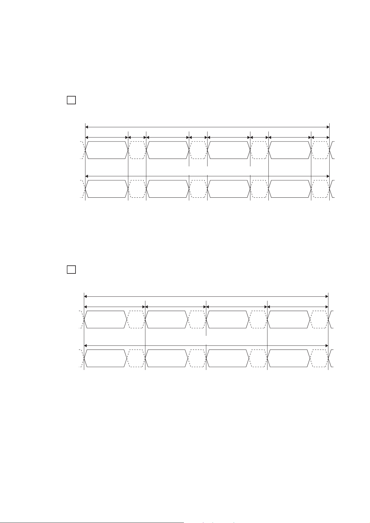
(b) With a conversion speed of 400μs
Ex.
Ex.
1ms
CH1
1ms
CH2
1ms
CH3
1ms
CH4
CH1 CH2 CH3 CH4
Main A/D converter module
(conversion enabled
channels: CH1 to CH4)
Extension A/D converter
module (conversion enabled
channels: CH1 to CH4)
Sampling period of the main A/D converter module
Conversion
processing
Processing
time
Conversion
processing
Processing
time
Conversion
processing
Processing
time
Conversion
processing
Processing
time
Sampling period of the extension A/D converter module
Conversion
processing
Processing
time
Conversion
processing
Processing
time
Conversion
processing
Processing
time
Conversion
processing
Processing
time
Between the conversion processing (400μs) of each channel, processing time (100μs) is generated. Therefore,
the sampling period is given by the following:
Sampling period = (Conversion speed (400μs) + Processing time (100μs)) × Number of conversion enabled
channels
Assuming that the conversion speed setting is 400μs and the number of conversion enabled channels is
4 for both the main A/D converter module and the extension A/D converter module
Sampling period of the main A/D converter module
400μs
Main A/D converter module
(conversion enabled
channels: CH1 to CH4)
Extension A/D converter
module (conversion enabled
channels: CH1 to CH4)
CH1
Conversion
processing
CH1 CH2 CH3 CH4
Conversion
processing
Sampling period of the main A/D converter module = (400μs + 100μs) × 4 = 2000μs =2ms
Sampling period of the extension A/D converter module = (400μs + 100μs) × 4 = 2000μs =2ms
(c) With a conversion speed of 1ms
With a conversion speed of 1ms, the time interval is 1ms including the processing time (100μs). Therefore, the
sampling period is given by the following:
Sampling period = Conversion speed (1ms) × Number of conversion enabled channels
Assuming that the conversion speed setting is 1ms and the number of conversion enabled channels is 4
for both the main A/D converter module and the extension A/D converter module
100μs 400μs
Processing
time
Conversion
processing
Sampling period of the extension A/D converter module
Processing
time
Conversion
processing
CH2
100μs 400μs
Processing
time
Processing
time
Conversion
processing
Conversion
processing
CH3
100μs 400μs
Processing
time
Processing
time
Conversion
processing
Conversion
processing
CH4
100μs
Processing
time
Processing
time
92
Sampling period of the main A/D converter module = 1ms × 4 = 4ms
Sampling period of the extension A/D converter module = 1ms × 4 = 4ms
Page 95

CHAPTER 8 FUNCTIONS
Ex.
100μs
CH1
100μs 100μs
CH2
100μs 100μs
CH3
100μs 100μs
CH4
100μs
CH1 CH2 CH3 CH4
Main A/D converter module
(conversion enabled
channels: CH1 to CH4)
Extension D/A converter
module (conversion enabled
channels: CH1 to CH4)
Sampling period of the main A/D converter module
Conversion
processing
Processing
time
Conversion
processing
Processing
time
Conversion
processing
Processing
time
Conversion
processing
Processing
time
Conversion period of the extension D/A converter module
Conversion
processing
Processing
time
Conversion
processing
Processing
time
Conversion
processing
Processing
time
Conversion
processing
Processing
time
If the number of conversion enabled channels is different between a main A/D converter module and an extension A/D
converter module, the main A/D converter module and the extension A/D converter module perform A/D conversion at each
different sampling period.
For example, assuming the following settings:
• Conversion speed setting: 100μs
• Conversion enabled channels of the main A/D converter module: CH1, CH2, CH3 (number of conversion enabled
channels: 3)
• Conversion enabled channels of the extension A/D converter module: CH1, CH2 (number of conversion enabled
channels: 2)
Sampling period of the main A/D converter module
Main A/D converter module
(conversion enabled
channels: CH1 to CH3)
Extension A/D converter
module (conversion enabled
channels: CH1 and CH2)
100μs
CH1
Conversion
processing
Sampling period of the extension A/D converter module
CH1 CH2 CH1 CH2
Conversion
processing
100μs 100μs
Processing
time
Processing
time
Conversion
processing
Conversion
processing
CH2
100μs 100μs
Processing
time
Processing
time
Conversion
processing
Conversion
processing
CH3
100μs 100μs
Processing
time
Processing
time
Conversion
processing
Conversion
processing
CH1
Sampling period of the main A/D converter module = (Conversion speed (100μs) + Processing time (100μs)) × 3 = 600μs
Sampling period of the extension A/D converter module = (Conversion speed (100μs) + Processing time (100μs) × 2 =
400μs
(3) When an extension D/A converter module is connected to a main A/D
converter module
When an extension D/A converter module is connected to a main A/D converter module, the conversion speed is
fixed to 100μs for the main A/D converter module and the extension D/A converter module. The setting of the
conversion speed switch (address: 0001H) is ignored. In addition, between the conversion processing of each
channel, processing time (100μs) is generated.
Therefore, the sampling period of the main A/D converter module is given by the following:
Sampling period = (Conversion speed (100μs) + Processing time (100μs)) × Number of conversion enabled
channels
100μs
Processing
time
Processing
time
8
8.5 Conversion Speed Switch Function
Assuming that the number of conversion enabled channels is 4 for both the main A/D converter module
and the extension D/A converter module
Sampling period of the main A/D converter module = (100μs + 100μs) × 4 = 800μs
Sampling period of the extension D/A converter module = (100μs + 100μs) × 4 = 800μs
93
Page 96
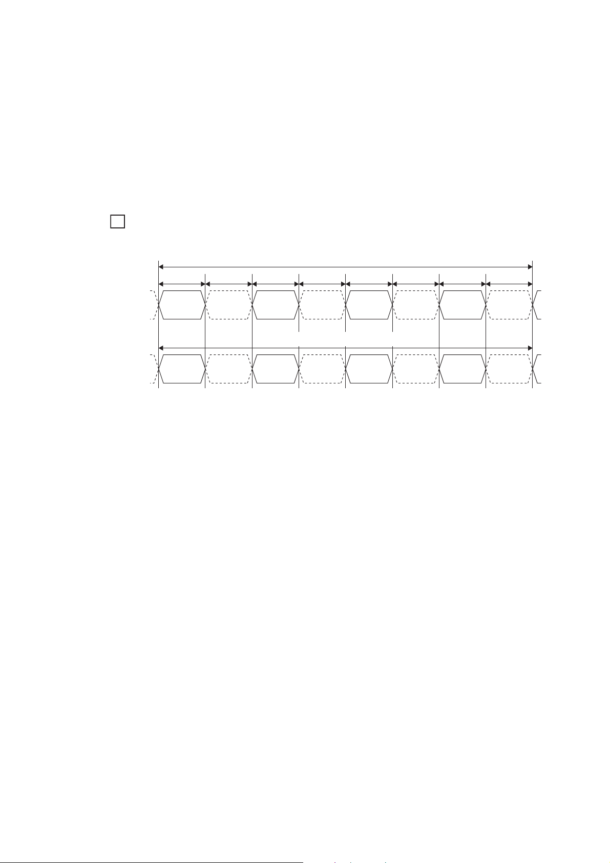
(4) When an extension A/D converter module is connected to a main D/A
Ex.
100μs
CH1
100μs 100μs
CH2
100μs 100μs
CH3
100μs 100μs
CH4
100μs
CH1 CH2 CH3 CH4
Main D/A converter module
(conversion enabled
channels: CH1 to CH4)
Extension A/D converter
module (conversion enabled
channels: CH1 to CH4)
Conversion period of the main D/A converter module
Conversion
processing
Processing
time
Conversion
processing
Processing
time
Conversion
processing
Processing
time
Conversion
processing
Processing
time
Sampling period of the extension A/D converter module
Conversion
processing
Processing
time
Conversion
processing
Processing
time
Conversion
processing
Processing
time
Conversion
processing
Processing
time
converter module
When an extension A/D converter module is connected to a main D/A converter module, the conversion speed is
fixed to 100μs for the main D/A converter module and the extension A/D converter module. In addition, between
the conversion processing of each channel, processing time (100μs) is generated.
Therefore, the sampling period of the extension A/D converter module is given by the following:
Sampling period = (Conversion speed (100μs) + Processing time (100μs)) × Number of conversion enabled
channels
Assuming that the number of conversion enabled channels is 4 for both the main D/A converter module
and the extension A/D converter module
Sampling period of the main D/A converter module = (100μs + 100μs) × 4 = 800μs
Sampling period of the extension A/D converter module = (100μs + 100μs) × 4 = 800μs
94
Page 97
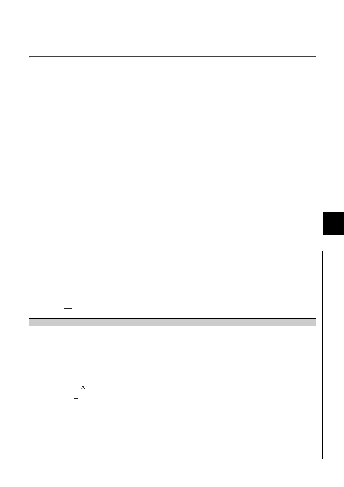
8.6 A/D Conversion Method
Ex.
Number of processing times (times) =
Setting time
Sampling period
= 9.375 (times) Rounded down to the nearest whole number
Nine times of measurement is performed to output the average value.
15
(4 0.4)
Set whether to perform sampling processing or averaging processing for each channel.
(1) Sampling processing
This processing performs A/D conversion on analog input values in sequence. The converted values at this time
are referred to as digital operation values.
For a main A/D converter module, digital operation values are stored into CH Digital operation value (RWr2 to
RWr5) at every sampling periods. For an extension A/D converter module, digital operation values are stored into
CH Digital operation value (RWr12 to RWr15) at every sampling periods.
The sampling period of the main A/D converter module and the extension A/D converter module depends on the
conversion speed setting and the number of conversion enabled channels. For details, refer to the following:
• Conversion Speed and Sampling Period ( Page 90, Section 8.5.1)
(2) Averaging processing
This processing performs averaging processing on digital operation values for each channel, storing the average
values into CH Digital operation value (RWr2 to RWr5, RWr12 to RWr15).
There are three types of averaging processing as follows:
• Time average
• Count average
• Moving average
CHAPTER 8 FUNCTIONS
8
(a) Time average
This processing performs A/D conversion for a set time and averages the total excluding the maximum and
minimum values, storing the average value into CH Digital operation value (RWr2 to RWr5, RWr12 to
RWr15).
The number of processing times varies depending on the sampling period.
The number of processing times assuming the following settings with no extension module connected
Item Setting
Number of channels used (number of channels where A/D conversion is enabled) 4 channels (CH1 to CH4)
Conversion speed 400μs/channel
Setting time 15ms
For the time average, the valid lower limit value to be set is given by: Minimum number of processing times, or
4 × Sampling period.
8.6 A/D Conversion Method
95
Page 98
For the time average, the valid lower limit value to be set is given by: Minimum number of processing times, or 4 × Sampling
Ex.
period.
Example: A maximum of 4 channels is used (conversion speed: 1ms/channel)
(1ms × 4) × 4 = 16ms
If the number of processing times falls below four due to the set time, an error occurs (error code: 020), where the digital
operation value becomes 0.
(b) Count average
This processing performs A/D conversion for a set number of times and averages the total excluding the
maximum and minimum values, storing the average value into CH Digital operation value (RWr2 to RWr5,
RWr12 to RWr15).
The time taken to store the average value obtained by count average into CH Digital operation value (RWr2
to RWr5, RWr12 to RWr15) varies depending on the sampling period.
Number of processing times = Set number of times × Sampling period
Processing times assuming the following settings with no extension module connected:
Item Setting
Number of channels used (number of channels where A/D conversion is enabled) 4 channels (CH1 to CH4)
Conversion speed 400μs/channel
Set number of times 20 times
20 × (4 × 0.4) = 32.0 (ms)
→ An average value is output every 32.0 ms.
Because the count average requires a sum of at least two counts except the maximum and minimum values, the set number
of times should be set to four or more.
96
Page 99
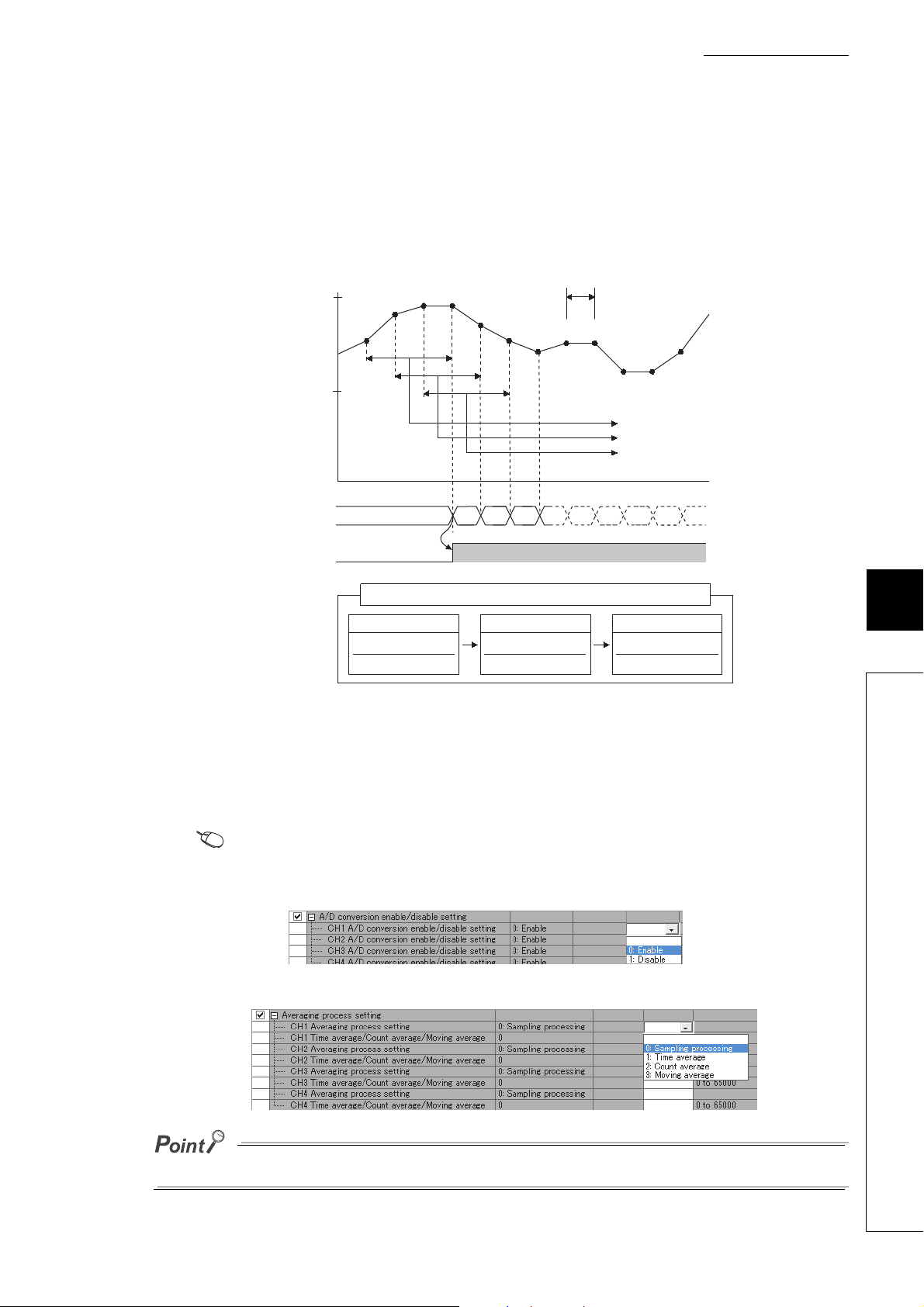
CHAPTER 8 FUNCTIONS
1st storage (a)
1) + 2) + 3) + 4)
4
2) + 3) + 4) + 5)
4
3) + 4) + 5) + 6)
4
2nd storage (b) 3rd storage (c)
Changes of data of CH1 Digital operation value (RWr2, RWr12)
1)
2)
3) 4)
5)
6)
7)
8) 9)
10)
11)
12)
0
0
(a) (b) (c)
3rd storage (c)
Time [ms]
2nd storage (b)
1st storage (a)
Sampling period
Digital output value
CH1 Digital operation
value (RWr2, RWr12)
CH1 A/D conversion
completed flag
(RX10, RX20)
ON
16000
8000
(c) Moving average
This processing averages the digital output values taken in at each sampling cycle for a specified number of
times, storing the average value into CH Digital operation value (RWr2 to RWr5, RWr12 to RWr15).
Because the averaging processing is performed on a moving set of sampling processing, the latest digital
operation values can be obtained.
The moving average processing for a set number of times of four is shown below:
(3) Setting procedure
The setting procedure for the main A/D converter module is as follows:
(a) Sampling processing
1. Set "Method selection" to "Parameter write".
2. In "Basic module parameter", set "CH A/D conversion enable/disable setting" to "0: Enable".
3. In "Basic module parameter", set "CH Averaging process setting" to "0: Sampling processing".
"CC IE Field Configuration" window Select the main A/D converter module from "List of stations"
[CC IE Field Configuration] [Online] [Parameter Processing of Slave Station]
8
8.6 A/D Conversion Method
For the extension A/D converter module, make the settings for each item of "Ext. module 1_Module parameter".
97
Page 100
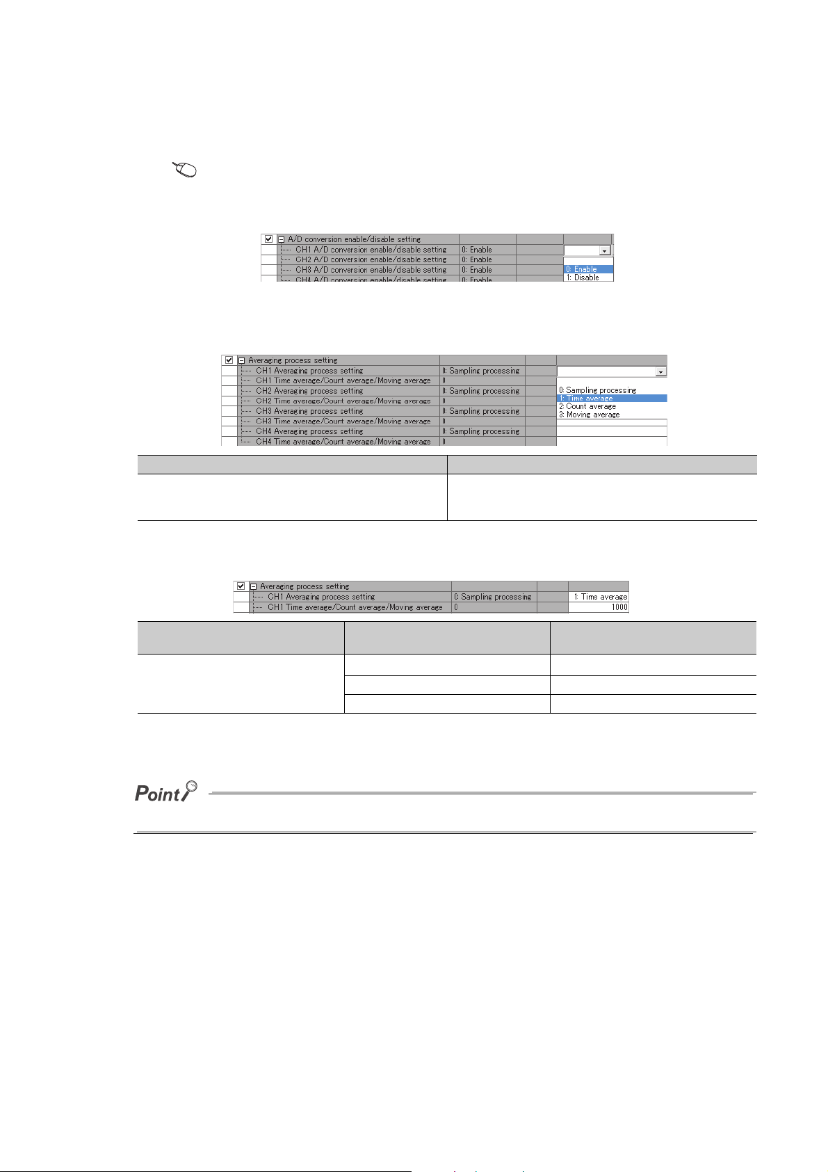
(b) Averaging processing
1. Set "Method selection" to "Parameter write".
"CC IE Field Configuration" window Select the main A/D converter module from "List of stations"
[CC IE Field Configuration] [Online] [Parameter Processing of Slave Station]
2. In "Basic module parameter", set "CH A/D conversion enable/disable setting" to "0: Enable".
3. In "Basic module parameter", specify the type of averaging processing for "CH Averaging
process setting".
Setting item Setting range
• 1: Time average
CH Averaging process setting
• 2: Count average
• 3: Moving average
4. In "Basic module parameter", set the value of averaging processing in "CH Time average/Count
average/Moving average".
Setting item
CH Time average/Count average/Moving
average
*1 For time average, set a value of (4 × Sampling period) ms or more. A value that does not satisfy this condition results in
the error code (020H, 120H) being stored in Latest error code (RWr0), Error flag (RXA) turning on, and the ERR.
LED lighting up. In CH Digital operation value (RWr2 to RWr5, RWr12 to RWr15), 0 is stored.
For the extension A/D converter module, make the settings for each item of "Ext. module 1_Module parameter".
Selected processing for "CH Averaging
process setting"
1: Time average
2: Count average 4 to 65000 (times)
3: Moving average 2 to 128 (times)
*1
2 to 5000 (ms)
Setting range
98
 Loading...