

Page 1
(
)
10/100M
Industrial Switching HUB
NZ2EHF-T8
User’s Manual
Powered by CONTEC
This product was jointly developed and m anufactured by Mitsubishi and
CONTEC.
Note that some of the warranty on this product differs from that on other
products (MELSEC-Q or MELSEC-L series).
Refer to "Terms of Warranty”.
MODEL NZ2EHF-T8-U
MODEL
CODE
13J247
IB(NA)-0800461-A(1007)MEE
© 2010 MITSUBISHI ELECTRIC CORPORATION
Page 2

Precautions regarding Warranty and Specifications
This product was jointly developed and manufactured by Mitsubishi and CONTEC.
Note that there are some precautions regarding warranty and specifications of the product.
<Warranty>
- The gratis warrant y term of the product shal l be for one (1) year a fter the date of delivery or for eighte en (18)
months after manu facturing, whichever is less .
- The onerous repair term after discontinuatio n of production shall be for s ix (6) years.
- Mitsubishi shall mainl y replace products that need repair .
- It may take some time to respond to the prob lem or repair the product dep ending on the condition and t iming.
<Specifications>
- General s pecifica tions ar e different.
NZ2EHF-T8 MELSEC-Q Series
Operating a mbient temperature 0 to 50°C 0 to 55°C
Operating ambient humidity 10 to 90%RH 5 to 95%RH
Storage ambien t temperature -10 to 60°C -25 to 75°C
Storage ambient humidity 10 to 90%RH 5 to 95%RH
- EMC standards that are applicable to the produc ts differ.
NZ2EHF-T8 MELSEC-Q Series
EMC standards EN55022, EN61000-6-2 EN61131-2
1
Page 3
Safety Precautions
Review the following definitions and precautions to use the product safely.
Safety Information
This document provides safety information using the following symbols to prevent accidents resulting in
injury or death and the destruction of equipment and resources. Review the meanings of these labels to
operate the equipment safely.
WARNING indicates a potentially hazardous situation which, if not avoided, could
WARN I NG
result in death or serio us injur y.
CAUTION indicates a potentially hazardous situation which, if not avoided, may result
CAU TION
in minor or mode rate inju ry or in p ropert y dama ge.
Handling Precautions
WA RN I N G
- Do not use the product where it is exposed to flammable or co rrosive gas. Failure to do so ma y result in an
explosion, fire, electr ic shock, or failure.
- The product could be very hot in the operatio n. Please do not touch wi th hands or body. It may ca use burns.
- To avoid electric shock, please do not touch the system with a wet hand.
CAU T I ON
- The link speed value (e.g., 100Mbps) of the transmission rate used in this manual is the theoretical maximum value of
the wired LAN standard and does not indicate the actual data transmission speed.
- Frame loss could occur depending on the conne ction destination or insta lled environment.
- As this product conta ins precision electronic components, d o not use or store it in a place subject to shock or
vibration. Doing s o may cause malfunction, heat generation, fault, or damage.
- Ground the FG ter minal to a protective grou nd conductor.
- Place the cables in a duct or c lamp them. If not, dangling cable may swing or inad vertently be pulled, resulting in
damage to the module or cables or malfunction due to po or contact.
- When disconnecting the communicati on cable or power cable from the module, do not pul l the cable by the cable
part.
- Correctly connect the power cables to the HUB unit.
- Do not install control lines or communication cables together with the main circuit lines or power cables. Keep a
distance of 100 mm or more between them. Fai lure to do so may result in mal function due to noise.
- Prevent foreign matter such as d ust or wire chips from entering the module. S uch foreign matter can cause a fire,
failure, or mal function.
- Do not use or store the product in a hot or cold place, or in a place that is subject to severe temperature changes.
Doing so may cause malfunction, heat generation, fault, or damage.
2
Page 4

- Do not use or stor e the product in a place s ubject to direct sunligh t or near a heating device, s uch as a stove. And do
not use or store t he product near equipment g enerating a strong magne tic field or radio waves. Do ing so may cause
malfunction, heat generation, fault, or damage.
- Do not use or store this product in the presence of chemicals.
- Do not use this pr oduct in extremely humid or dusty locations. It is extr emely dangerous to use this p roduct in
locations where water, other fluid, or conductive dust may enter the interior o f the unit. To use this product in such
an environment, install it in a dust-proof control panel, for example.
- If you notice abnor mal odor or
- If you find a fau lt or other abnormality (b ad smell or excessive heat) , unplug the power termina l connector and then
contact the distrib utor.
- Do not open the product casing. Mitsubishi will disclaim any responsibility for products whose casing has been opened.
- Do not modify the product. Mitsubishi will bear no responsibility for any problems, etc., resulting from modifying the
product.
- To clean this product, gently wipe it with a soft cloth soaked with water or a neutr al detergent. Do not use benzene,
paint thinner, or oth er volatile solvents as they can cause the coating to discolor or peel off.
- The specifications of th is product are subject to change with out notice because of function addi tion and quality
improvement.
Even when using the product continuousl y, read the user's manual and c heck the contents.
- If you move or tra nsfer the product, make sur e provide this manual with the product.
- Regardless of the foregoing statements, Mitsubishi is not liab le for any damages whatsoe ver (including damages for
loss of business p rofits) arising out of the use or inability to use this Mitsubishi product or t he information contained
herein.
overheating, please disconnect the power cable immediately.
FCC PART15 class A Notice
NOTE
This equ ipment h as been tested a nd found to comply wit h the lim its for a Class A digital d evice,
pur suant to part 15 of th e FCC Rules. Th ese limits a re designed to provide reas onable protection
against ha rmful interference when the equipment is operated in commercial environment.
This equ ipment ge nerat es, uses, an d can ra diate ra dio frequency ener gy and, if not in stalled an d
us ed in acco rda nce w ith th e ins tr uct ion m an ual , ma y cau se h ar mfu l int er feren ce t o ra dio
commun ications. Opera tion of this equ ipment in a residen tial are a is likely to caus e harmfu l
interference at his own expense.
WARN ING TO USE R
Change or modifications not expressly approved the manufacturer can void the user's authority to
operat e this equ ipment .
3
Page 5

CONDITIONS OF USE FOR THE PRODUCT
(1) Mitsubishi programmable controller ("the PRODUCT") shall be used in conditions;
i) where any problem, fault or failure occurring in the PRODUCT, if any, shall not lead to any
major or serious accident; and
ii) where the backup and fail-safe function are systematically or automatically provided outside of
the PRODUCT for the case of any problem, fault or failure occurring in the PRODUCT.
(2) The PRODUCT has been designed and manufactured for the purpose of being used in gene ral
industr ies.
MITSUBISHI SHALL HAVE NO RESPONSIBILITY OR LIABILITY (INCLUDING, BUT NOT
LIMITED TO ANY AND ALL RESPONSIBILITY OR LIABILITY BASED ON CONTRACT,
WARRANTY, TORT, PRODUCT LIABILITY) FOR ANY INJURY OR DEATH TO PERSONS
OR LOSS OR DAMAGE TO PROPERTY CAUSED BY the PRODUCT THAT ARE OPERATED
OR USED IN APPLICATION NOT INTENDED OR EXCLUDED BY INSTRUCTIONS,
PRECAUTIONS, OR WARNING CONTAINED IN MITSUBISHI'S USER, INSTRUCTION
AND/OR SAFETY MANUALS, TECHNICAL BULLETINS AND GUIDELINES FOR the
PRODUCT.
("Proh ibited A pplicat ion")
Prohib ited App lications includ e, but no t limited to, the u se of the PRODUCT in;
- Nuclear Power Plants and any other power plants operated by Power companies, and/or any
other cases in which the public could be affected if any problem or fault occurs in the
PRODUCT.
- Railway companies or Public service purposes, and/or any other cases in which establishment
of a special quality assurance system is required by the Purchaser or End User.
- Aircraft or Aerospace, Medical applications, Train equipment, transport equipment such as
Elevator and Escalator, Incineration and Fuel devices, Vehicles, Manned transportation,
Equipment for Recreation and Amusement, and Safety devices, handling of Nuclear or
Hazardous Materials or Chemicals, Mining and Drilling, and/or other applications where there
is a sign ificant r isk of injury to the pub lic or pro perty.
4
Page 6
Packing List
Thank you for purcha sing this Mitsubishi produ ct.
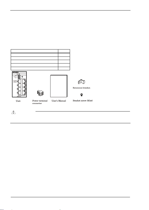
The product package contains the items listed below.
Check the contents of the product package.
If you discover any damaged or missing items, contact the distributor.
Contents
Industrial switching HUB unit (NZ2EHF-T8) 1
Power terminal connector 1
User’s Manual 1
Retention bracket 1
Bracket screw M3x6 1
Name Pcs.
CAU T I ON
To operate this product, a power supply (12-24VDC±5%) is required separately. For power supply, see Chapter 2,
Part Names and Settings, “Power Supply”.
- This document, in whole or in part, may not be r eproduced without permiss ion.
- This document is subject to change without notice at any ti me.
- While we are doing our best to ensure this document has no error, should you have any questions or find any
ommissions or si milar, consult the distributor .
5
Page 7

Table of Contents
Packing List ........................................................................................................................................5
1. Before Using th e Product 7
About the Unit ....................................................................................................................................7
Features........................................................................................................................................7
Environment.................................................................................................................................7
Inspection.....................................................................................................................................8
Storage......................................................................................................................................... 8
Disposal .......................................................................................................................................8
2. Part Names and Se ttings 9
Part Names and Functions...................................................................................................................9
3. Setup of Hardware 11
Mounting/Removing a Unit on/from a DIN Rail...............................................................................11
Mounting Procedure................................................................................................................... 11
Removing Procedure............................................................................................................. .....12
Attaching a retention bracket.............................................................................................................13
Attachment.................................................................................................................................13
4. Connecting to a Network 14
Network Cables.................................................................................................................................14
Connecting to Programmable Controllers, Personal Computers, Additional HUB Units, or Bridges.14
Connection Restrictions for 100BASE-TX Repeater HUBs .......................................................15
Connection Restrictions for 10BASE-T Repeater HUBs ............................................................15
5. System Reference 16
Specifications....................................................................................................................................16
External Dimensions .........................................................................................................................17
EMC Directive..................................................................................................................................18
WARRANTY ...................................................................................................................................19
6
Page 8

1. Before Using the Produc t
1. Before Using the Product
This chapter provides information you should know before using the product.
About the Unit
NZ2EHF-T8 is an IEEE -802.3 (Etherne t)/IEEE-802.3u (F ast Ethernet)-co mpliant 8-port switc hing HUB
unit, equipped with full-duplex communication support, AutoMDI/MDI-X feature, and auto-recognition
function of communication rate (10/100Mbps) and communication method (half/full duplex) using the
auto-negotiation feature. NZ2EHF-T8 uses Category 3, 5, 5e, or 6 UTP (unshielded twist pair) cables or
STP (shielded twist pair) cables. For 100Mbps communication rate, use cables equal to or greater than
Category 5.
Please read this manual carefully so that you can build a system by connecting the switching HUB unit to
external devices.
Features
- The Auto MDI/MDI-X feature can automatically recognize the cable type, straight-through cable or
crossover cable, to prevent problems using the wrong cable type.
Also, the auto-negotiation feature can automatically recognize and choose the best communication
rate (10/100Mbps) and method (half/full duplex) available.
- The unit is equipped with a 35mm DIN rail mounting mechanism as standard.
- The power connector includes an FG terminal.
Environment
Use this product in the following environment. If used under environmental conditions exceeding these
ranges, the board may overheat, malfunction, or cause a failure.
Operating ambient temperature
0 to 50°C
Operating ambient humidity
10 to 90%RH (No condensation)
Corrosive gases
None
Floating dust particles
small amounts (non excessive)
7
Page 9

1. Before Using the Produc t
Inspection
Inspect the product periodically as follows to use it safely.
Storage
When sto ring this produ ct, keep it in its o rigina l packin g form.
(1) Put the unit in the storage bag.
(2) Wrap it in the packing material, then put it in the box.
(3) Store the package at room temperature at a place free from direct sunlight, moisture, shock, vibration,
magnetism, and static electricity.
Disposal
When disposing of the product, follow the disposal procedures stipulated under the relevant laws and
municipal ordinances.
8
Page 10

2. Part Names and Settings
2. Part Names and Settings
Part Names and Functions
Figure 2.1. Part names
Table 2.1. LED indicators
Name Status Color Display
POWER LED POWER Green OFF : Power off
Comm. status LED 10Mbps
Table 2.2. Connectors
Power connector
100Mbps
Name Function
Power terminal connector (included in the package): MC1,5/3-ST-3,5 (made by Phoenix
Contact Inc.)
The applicable cable is AWG28-16. (The cable length must meet the power supply
specifications.)
Secure the conne ctor with a retention bracket. Con nect the power cable to the powe r
terminal connector by screw connection.
The fastening torque range is 0.22 to 0.25Nm.
Power connector MC1,5/3-G-3,5 (Phoenix Contact)
Pin number Signal Description
1 Vi+ Power (12-24VDC±5%)
2 Vi- Power (GND)
3 FG Frame Grand
ON : Power on
OFF : No LINK
Orange
ON : LINK
Green
Flashing : ACT (Data send/receive)
9
Page 11

2. Part Names and Settings
Table 2.3. 10BASE-T/100 BASE-TX
Name Function
10BASE-T/
100BASE-TX port
Ports 1 to 8
Use these ports to conne ct personal computers, additional HUB uni ts, bridges, or other
devices.
Communication rate (10/100Mbps) and communication method (half/full duplex) can
be automatically r ecognized.
Using the Auto MDI /MDI-X function, the cable type
cable) can be automa tically recognized.
(straight-through or crossover
Power Supply
Use a power supply capable of establishing 11.6VDC or higher within 50ms. Power supplies that can not
meet this requirement may cause device failures or accidents.
Input voltage (V)
25.2
24
12
11.6
Pin name Signal Description
1 TX+ Transmit (+)
2 TX- Transmit (-)
3 RX+ Receive (+)
4 - -
5 - -
6 RX- Receive (-)
7 - -
8 - -
50
Time (ms)
Figure 2.2. Time required to establish certain voltage
The AC/DC power supply connected to the unit must be a CE-marked product.
Ground the FG terminal to a protective grou nd conductor.
Recommended power su pply: PS5R-SF24 (made b y IDEC Corporation)
10
Page 12

3. Setup of Hardware
3. Setup of Hardware
Mounting/Removing a Unit on/from a DIN Rail
Mounting Procedure
(1) Lifting the fixing hook of a unit with a flathead screwdriver renders it into a lock-enabled condition.
Figure 3.1. Mounting a unit on a DIN rail < 1 / 3 >
(2) Hook the unit from the upper part of a DIN rail, and push the lower part of the unit to the DIN rail.
Figure 3.1. Mounting a unit on a DIN rail < 2 / 3 >
(3) The fixing hook automatically locks so that the unit can be mounted with one simple motion.
Figure 3.1. Mounting a unit on a DIN rail < 3 / 3 >
11
Page 13

Removing Procedure
(1) Lower the fixing hook of a unit to unlock it.
3. Setup of Hardware
Figure 3.2. Removing a unit from a DIN rail < 1 / 3 >
(2) With the fixing hook unlocked, pull the lower part of the unit toward you.
Figure 3.2. Removing a unit from a DIN rail < 2 / 3 >
(3) By lifting the unit, you can easily remove it from the DIN rail.
Figure 3.2. Removing a unit from a DIN rail < 3 / 3 >
12
Page 14

3. Setup of Hardware
Attaching a retention bracket
Attachment
(1) Plug in the power terminal connector to the power connector and attach the retention bracket using a
bracket screw.
Figure 3.3. Attaching a retention bracket
13
Page 15

4. Connecting to a Net work
4. Connecting to a Network
Network Cables
Cables meeting the following specifications should be used:
- 10BASE-T: Category 3 or higher UTP, STP cab le
- 100BASE-TX : Category 5 or higher UPT, STP cable
- There are two types for UTP and STP cables: a straight-through cable and a crossover cable. The
Auto MDI/MDI-X feature allows connections using either type of a cable.
Connecting to Programmable Controllers,
Personal Computers, Additional HUB Units, or
Bridges
When connecting a programmable controller, personal computer, additional HUB unit, bridge, or other
device, connect it to any 10BASE-T/100BASE-TX port of the switching HUB unit using either a
straight-throu gh or crossover cable.
Figure 4.1. Connection example
14
Page 16

4. Connecting to a Net work
Connection Restrictions for 100BASE-TX Repeater HUBs
Up to two stages of cascade connections are possible with Class II 100BASE-TX repeater HUBs. In
additio n, the m aximum total leng th of ca bles (1) (2) (3) is 205m o r less. Fo r details, refe r to the user's
manual for the 100BASE-TX repeater HUB used.
Figure 4.2. Connection restrictions for 100BASE-TX repeater HUBs (Class II)
Connection Restrictions for 10BASE-T Repeater HUBs
As many as four stages of 10BASE-T repeater HUBs can be connected using cascade connection. In
addition, the length of UTP or STP cable between cascaded HUBs is 100m or less. For details, refer to the
user's manual for the 10BASE-T repeater HUB used.
Figure 4.3. Connection restrictions for 10BASE-T repeater HUBs
15
Page 17

5. System Reference
5. System Reference
Specifications
Table 5.1. Specifications
Item Specifications
Ethernet standards IEEE802.3/IEEE802.3u -compliant
Data communication rate 10/100Mbps (auto-recognition)
Access method CSMA/CD
Communication method All ports: Full/Half duplex (auto-recognition)
Topology Star topology
Flow control Full Duplex : IEEE802.3x compliant flow control
Number of effective ports 8
Switching method Store and forward
Address table 1,024 entries
Buffer capacity 512Kbyte
Aging time 200 to 300s
LED indicator POWER (green) , Link/ACT 10M (orange) , Link/ACT 100M (green)
Power supply voltage 12V - 24VDC±5%
FG terminal The power connector is equipped with FG terminal.
Power consumption (Max.) 0.22A at 12VDC, 0.15A at 24VDC
Physical dimensions (mm) 52.4 (W) x 64.7 (D) x 94.0 (H) (exclusive of protrusions)
Weight 160g
Installation method Mounts onto a 35mm DIN rail with one motion. The unit is equipped with a
Table 5.2. Installation environment requirements
Item Specifications
Operating ambient temperature 0 to 50°C
Storage ambient temperature -10 to 60°C
Ambient humidity 10 to 90%RH (No condensation)
Floating dust part icles Tolerant o f small amounts (non excessi ve)
Corrosive gases None
Line-noise AC line/2kV, Signal line/1kV (JIS C61000-4-4 Level 3, IEC61000-4-4 Level 3)
Noise
Electrostatic
immunity
discharge immunity
Vibration
Sweep resistance
resistance
Shock resistance 15G, sine half-wave pulse for 11ms each in X, Y, and Z direc tions
Grounding G round the FG terminal to the prote ctive ground conductor.
Installation lo cation Inside a control p anel
Half Duplex :Back pressure
mounting mechanism as standard.
Contact discharge/4kV (JIS C61000-4-2 Level 2, IEC61000-4-2 Level 2)
Air discharge/8kV (JIS C61000-4-2 Level 3, IEC61000-4-2 Level 3)
10 to 57Hz/half amplitude 0.15mm,57 to 150Hz/2.0G
40minutes each in X, Y, and Z directions
(JIS C60068-2-6-compliant, IEC60068-2-6-compliant)
(JIS C60068-2-27-compliant, IEC60068-2-27-compliant)
16
Page 18

5. System Reference
External Dimensions
Figure 5.1. External dimensions
17
Page 19

5. System Reference
EMC Directive
Compliance with the EMC Directive, which is one of the EU directives, has been mandatory for the
products sold within EU member states since 1996.
To prove the compliance with the EMC Directive, manufactures must issue an EC Declaration of
Conformity and the products must bear a CE marking.
This product is comp liant to with EN55022, and EN61000-6-2.
(1) Authorized representative in EU member states
The authorized representative in EU member states will be:
Company name : Mitsubishi Electric Europe BV
Address : Gothaer stra sse 8, 40880 Ratingen, Germ any
18
Page 20

WARRANTY
Please confirm the following product warranty details before using this product.
1. Gratis Warranty Term and Gratis Warranty Range
If any faults or defects (hereinafter "Failure") found to be the responsibility of Mitsubishi occurs during
use of the product within the gratis warranty term, the product shall be repaired at no cost via the sales
representative or Mitsubishi Service Company.
However, if repairs are required onsite at domestic or overseas location, expenses to send an engineer
will be solely at the customer’s discretion. Mitsubishi shall not be held responsible for any
re-commissioning, maintenance, or testing on-site that involves replacement of the failed module.
[Gratis Warranty Term]
The gratis warranty term of the product shall be for one year after the date of purchase or delivery to a
designated place.
Note that after manufacture and shipment from Mitsubishi, the maximum distribution period shall be
six (6) months, and the longest gratis warr anty term after manu facturing shall be eightee n (18) months.
The gratis warranty term of repair parts shall not exceed the gratis warranty term before repairs.
[Gratis Warranty Range]
(1) The range shall be limited to normal use within the usage state, usage methods and usage
environment, etc., which follow the conditions and precautions, etc., given in the instruction
manual, user's manua l and caution labels on t he product.
(2) Even within the gratis warranty term, repairs shall be charged for in the following cases.
1. Failure occurring from inappropriate storage or handling, carelessness or negligence by the user.
Failure caused by the user's hardware or software design.
2. Failure caused by unapproved modifications, etc., to the product by the user.
3. When the Mitsubishi product is assembled into a user's device, Failure that could have been
avoided if functions or structures, judged as necessary in the legal safety measures the user's
device is subject to or as necessary by industry standards, had been provided.
4. Failure that could have been avoided if consumable parts (battery, backlight, fuse, etc.)
designated in the instruction manual had been correctly serviced or replaced.
5. Failure caused by external irresistible forces such as fires or abnormal voltages, and Failure
caused by force majeure such as earthquakes, lightning, wind and water damage.
6. Failure caused by reasons unpredictable by scientific technology standards at time of shipment
from Mitsubishi.
7. Any other failure found not to be the responsibility of Mitsubishi or that admitted not to be so by
the user.
19
Page 21

2. Onerous repair term after discontinuation of production
(1) Mitsubishi shall accept onerous product repairs for six (6) years after production of the product is
discontinued.
Discontinuation of production shall be notified with Mitsubishi Technical Bulletins, etc.
(2) Product supply (inc luding repair par ts) is not available afte r production is discontinue d.
3. Overseas service
Overseas, repairs shall be accepted by Mitsubishi's local overseas FA Center. Note that the repair
conditions at each FA Center may differ.
4. Exclusion of loss in opportunity and secondary loss from warranty
liability
Regardless of the gratis warranty term, Mitsubishi shall not be liable for compensation of damages
caused by any cause found not to be the responsibility of Mitsubishi, loss in opportunity, lost profits
incurred to the user by Failures of Mitsubishi products, special damages and secondary damages
whether foreseeable or not , compensation for accidents, and compensation for damages to products
other than Mitsubishi products, replacement by the user, maintenance of on-site equipment, start-up
test run and other ta sks.
5. Changes in product specifications
The specifications given in the catalogs, manuals or technical documents are subject to change without
prior notice.
20
Page 22

Revisions
Print Date *Manual Number Revision
July 2010 IB(NA)-080046 1-A First edition
*The manual number is given on the bottom right of the cover.
21
Page 23

Page 24

 Loading...