

Mitsubishi Electric DLP NW30U, DLP NW31U-EST, NW30U User Manual

U
NW30U
This User Manual is important to you.
Please read it before using your projector.
DLP™ PROJECTOR
MODEL
NW30U
User Manual
EN-2
CAUTION
RISK OF ELECTRIC SHOCK
DO NOT OPEN
CAUTION
: TO REDUCE THE RISK OF ELECTRIC
SHOCK, DO NOT REMOVE COVER (OR BACK)
NO USER-SERVICEABLE PARTS INSIDE
REFER SERVICING TO QUALIFIED SERVICE
PERSONNEL.
The lightning fl ash with arrowhead symbol within an equilateral triangle is intended to alert
the user to the presence of uninsulated “dangerous voltage” within the product’s enclosure
that may be of suffi cient magnitude to constitute a risk of electric shock.
The exclamation point within an equilateral triangle is intended to alert the user to the
presence of important operating and maintenance (servicing) instructions in the literature
accompanying the appliance.
WARNING:
TO PREVENT FIRE OR SHOCK HAZARD, DO NOT EXPOSE THIS APPLIANCE TO RAIN OR MOISTURE.
CAUTION:
TO PREVENT ELECTRIC SHOCK, DO NOT USE THIS (POLARIZED) PLUG WITH AN EXTENSION CORD,
RECEPTACLE OR OTHER OUTLET UNLESS THE BLADES CAN BE FULLY INSERTED TO PREVENT BLADE
EXPOSURE.
NOTE:
SINCE THIS PROJECTOR IS PLUGGABLE EQUIPMENT, THE SOCKET-OUTLET SHALL BE INSTALLED NEAR
THE EQUIPMENT AND SHALL BE EASILY ACCESSIBLE.
WARNING
Use the attached specifi ed power supply cord. If
you use another power supply cord, it may cause
interference with radio and television reception.
This apparatus must be grounded.
DO NOT LOOK DIRECTLY INTO THE LENS WHEN
THE PROJECTOR IS IN THE POWER ON MODE.
CAUTION
The attached power cord is to be used exclusively for
this product. Never use it for other products.
CAUTION
Not for use in a computer room as defi ned in the
Standard for the Protection of Electronic Computer/
Data Processing Equipment, ANSI/NFPA 75.

EN-3
Contents
Important safeguards ........................................................................................................................4
Preparing your projector ....................................................................................................................6
Using the remote control ...................................................................................................................9
Setting up your projector .................................................................................................................10
Basic connections ...........................................................................................................................15
Basic operation ...............................................................................................................................19
Menu operation ...............................................................................................................................25
Adjusting projected images .............................................................................................................34
Network functions of this projector .................................................................................................39
Initial network settings .....................................................................................................................40
Advanced display utilities ................................................................................................................46
Advanced features ..........................................................................................................................61
Maintenance ....................................................................................................................................65
Troubleshooting ...............................................................................................................................66
Indicators .........................................................................................................................................70
Specifi cations ..................................................................................................................................71
Trademark, Registered trademark
• DLP™, Digital Micromirror Device, DMD, and DLP™ Link™ are all trademarks of Texas Instruments.
• HDMI, the HDMI logo and High-Defi nition Multimedia Interface are trademarks or registered trademarks of HDMI
Licensing LLC.
• Microsoft, Windows, Windows Vista, Windows Server, MultiPoint, Excel, and PowerPoint are either registered
trademarks or trademarks of Microsoft Corporation in the United States and/or other countries.
• Mac, Mac OS, OS X, Finder, and Apple Store are trademarks of Apple Inc.
• Intel and Pentium are trademarks of Intel Corporation in the U.S. and/or other countries.
• PowerPC is a trademark of International Business Machines Corporation, registered in many jurisdictions
worldwide.
• IOS is a trademark or registered trademark of Cisco in the U.S. and other countries and is used under license.
• Android and Google are trademarks of Google Inc.
• MirrorOp, MirrorOp Receiver, and WiFi-Doc are registered trademarks, trademarks, or trade names of AWIND Inc.
• Wi-Fi is a registered trademark of the Wi-Fi Alliance.
• The trademark of PJLink is trademark applied for registration or registered trademark in Japan, the United States,
and other countries and areas.
• Crestron RoomView Connected is a trademark of Crestron Electronics, Inc.
• Other brand or product names are trademarks or registered trademarks of their respective holders.

EN-4
Important safeguards
Please read all these instructions regarding your
projector and retain them for future reference. Follow
all warnings and instructions marked on the projector.
1. Read instructions
All the safety and operating instructions should be
read before the appliance is operated.
2. Retain instructions
The safety and operating instructions should be
retained for future reference.
3. Warnings
All warnings on the appliance and in the operating
instructions should be adhered to.
4. Instructions
All operating instructions must be followed.
5. Cleaning
Unplug this projector from the wall outlet before
cleaning it. Do not use liquid aerosol cleaners. Use
a damp soft cloth for cleaning.
6. Attachments and equipment
Never add any attachments and/or equipment
without the approval of the manufacturer as such
additions may result in the risk of fi re, electric
shock or other personal injury.
7. Water and moisture
Do not use this projector near water or in contact
with water.
8. Accessories
Do not place this projector on an unstable cart,
stand, tripod, bracket or table. Use only with a
cart, stand, tripod bracket, or table recommended
by the manufacturer or sold with the projector.
Any mounting of the appliance should follow
the manufacturer’s instructions and should use
a mounting accessory recommended by the
manufacturer.
10. Power sources
This projector should be operated only from the
type of power source indicated on the marking
label. If you are not sure of the type of power,
please consult your appliance dealer or local
power company.
11. Power-cord protection
Power-supply cords should be routed so that
they are not likely to be walked on or pinched
by items placed upon or against them. Pay
particular attention to cords at plugs, convenience
receptacles, and points where they exit from the
appliance. Do not put the power cord under a
carpet.
12. Overloading
Do not overload wall outlets and extension cords
as this can result in a fi re or electric shock.
13. Objects and liquids
Never push objects of any kind through openings
of this projector as they may touch dangerous
voltage points or short-out parts that could result
in a fi re or electric shock. Never spill liquid of any
kind on the projector.
14. Servicing
Do not attempt to service this projector by yourself.
Refer all servicing to qualifi ed service personnel.
15. Damage requiring service
Unplug this projector from the wall outlet and refer
servicing to qualifi ed service personnel under the
following conditions:
(a) If the power-supply cord or plug is damaged.
(b) If liquid has been spilled, or objects have fallen
into the projector.
(c) If the projector does not operate normally after
you follow the operating instructions. Adjust
only those controls that are covered by the
operating instructions. An improper adjustment
of other controls may result in damage and
may often require extensive work by a qualifi ed
technician to restore the projector to its normal
operation.
(d) If the projector has been exposed to rain or
water.
(e) If the projector has been dropped or the
cabinet has been damaged.
(f)
If the projector exhibits a distinct change in
performance - this indicates a need for service.
16. Replacement parts
When replacement parts are required, be sure
that the service technician has used replacement
parts specifi ed by the manufacturer or parts
having the same characteristics as the original
part. Unauthorized substitutions may result in fi re,
electric shock or other hazards.
17. Safety check
Upon completion of any service or repair to this
projector, ask the service technician to perform
safety checks determining that the projector is in a
safe operating condition.
An appliance and cart combination should be
moved with care. Quick stops, excessive force and
uneven surfaces may cause the appliance and cart
combination to overturn.
9. Ventilation
Slots and openings in the cabinet are provided
for ventilation, ensuring reliable operation of the
projector and to protect it from overheating. Do
not block these openings or allow them to be
blocked by placing the projector on a bed, sofa,
rug, or bookcase. Ensure that there is adequate
ventilation and that the manufacturer’s instructions
have been adhered to.

EN-5
Important safeguards (continued)
WARNING:
Unplug immediately if there is something
wrong with your projector.
Do not operate if smoke, strange noise or odor comes out
of your projector. It might cause fi re or electric shock. In this
case, unplug immediately and contact your dealer.
Never remove the cabinet.
This projector contains high voltage circuitry. An inadvertent
contact may result in an electric shock. Do not attempt to
service this product by yourself. Please contact your dealer
when you want to fi x, adjust or inspect the projector.
• Safety lock:
When you open the cabinet, the projector is locked and
cannot be powered on anymore. In such a case, please
contact your dealer.
Do not modify this equipment.
It can lead to fi re or electric shock.
Do not keep using the damaged projector.
If the projector is dropped and the cabinet is damaged,
unplug the projector and contact your dealer for inspection.
It may lead to fi re if you keep using the damaged projector.
Be sure to unplug the power cord from the wall
outlet if the projector is fractured or deformed.
Otherwise, it may result in fi re or electric shock. Ask your
dealer for repair.
Do not face the projector lens to the sun.
It can lead to fi re.
Use correct voltage.
If you use incorrect voltage, it can lead to fi re.
Do not connect multiple electrical appliances
to a single wall outlet.
It can lead to fi re.
Do not extend the power cord.
It can lead to fi re.
Do not place the projector on uneven surface.
Place the projection on a leveled and stable surface only.
Please do not place equipment on unstable surfaces.
Do not look into the lens when it is operating.
It may hurt your eyes. Never let children look into the lens
when it is on.
Do not touch the air outlet grille and bottom
plate, which become hot.
Do not touch them or put other equipment in front of the
air outlet grille. The air outlet grille and bottom plate, when
heated, may cause injury or damage to other equipment.
Also, do not set the projector on the desk which is easily
affected by heat.
Do not look into the air outlet grille when
projector is operating.
Heat, dust, etc. may blow out of it and hurt your eyes.
Do not insert your fi ngers in the space
between the lens and the cabinet.
The lens may shift causing injury or damage to the projector.
Do not block the air inlet and outlet grilles.
If they are blocked, heat may be generated inside the
projector, causing deterioration in the projector quality and fi re.
Do not use fl ammable solvents (benzene, thinner,
etc.) and fl ammable aerosols near the projector.
Flammable substances may ignite causing fi re or breakdown
because the temperature inside the projector rises very high
while the light source is illuminating.
Do not use the projector with condensation on it.
It can lead to breakdown or other failure.
Place of installation
For safety’s sake, refrain from setting the projector at any
place subjected to high temperature and high humidity.
Please maintain an operating temperature, humidity, and
altitude as specifi ed below.
• Operating temperature:
Allowable operating temperature is +41°F (+5°C) to
+95°F (+35°C).
• Projection angles:
For use in the STANDARD mode, which allows all
projection angle of a front and rear direction. For use in
the HIGH ALTITUDE mode (see page 12), which allows
fl oor installation or ceiling installation only.
• Operating humidity: between 30% and 90%
• Never put any heat-producing device under the projector
so that the projector does not overheat.
• Do not attach the projector to a place that is unstable or
subjected to vibration.
• Do not install the projector near any equipment that
produces a strong magnetic fi eld. Also refrain from
installing near the projector any cable carrying a large
current.
• Place the projector on a solid, vibration free surface;
otherwise it may fall, causing serious injury to a child or
adult, and serious damage to the product.
• Do not stand the projector; it may fall, causing serious
injury and damage to the projector.
• Do not install the projector at an angle of a right and left
direction greater than 30° to the direction of the exhaust
vent downward, heat may be generated inside the
projector, causing deterioration in the projector quality
and life.
• Do not place the projector near air-conditioning unit,
heater, or humidifi er to avoid hot or moist air to the
exhaust and ventilation hole of the projector.
•
Do not place the projector in the following places.
Otherwise, a short circuit, heat generation, or melting of
the power cord coating may occur, causing fi re, electric
shock, product failure, or deformation.
• Outdoors or non air-conditioned place
• Place where a gas such as a hydrogen sulfi de is
generated (i.e. hot spring)
• Place where there is too much salt such as near the
coast
• We don’t recommend using the projector at an altitude
of 2700 meters or higher (When using the product at an
altitude of 1500 to 2700 meters above the sea level, set
the HIGH ALTITUDE MODE to HIGH ALTITUDE.). Use
at an altitude of 2700 meters or higher may affect the
projector’s life.
Do not place a container containing water or
other liquid on the projector.
If water spills on or enters the projector, it may result in fi re or
electric shock.
Do not put any object that is heavy or larger
than the outer frame on the projector.
Otherwise, the object may fall losing its balance and cause
injury.
Do not subject the projector to strong shocks or
vibrations. Do not handle the projector roughly.
The projector may be damaged, resulting in fi re or electric
shock.
EN-6
Preparing your projector
Checking accessories
The following accessories are provided with this projector. Check to be sure that all of the accessories are packed in
the package.
What’s included in the box
AC power cord* for the U.S. J2552-0063-03
for Europe J2552-0247-00
for the U.K. J2552-0065-02
for Australia J2552-0053-00
for South Korea J2552-0247-00
Computer cable J2552-0072-05
Remote control J8947-0355-00
Safety Manual/Quick Start up
CD-ROM
R6 (size-AA) battery (two)
Lens cap (attached to the projector)
Power cord holder
* One of power cords for the U.S., Europe, U.K., Australia, and South Korea is provided appropriately.
Important:
• The attached power cord is to be used exclusively for this product. Never use it for other products.
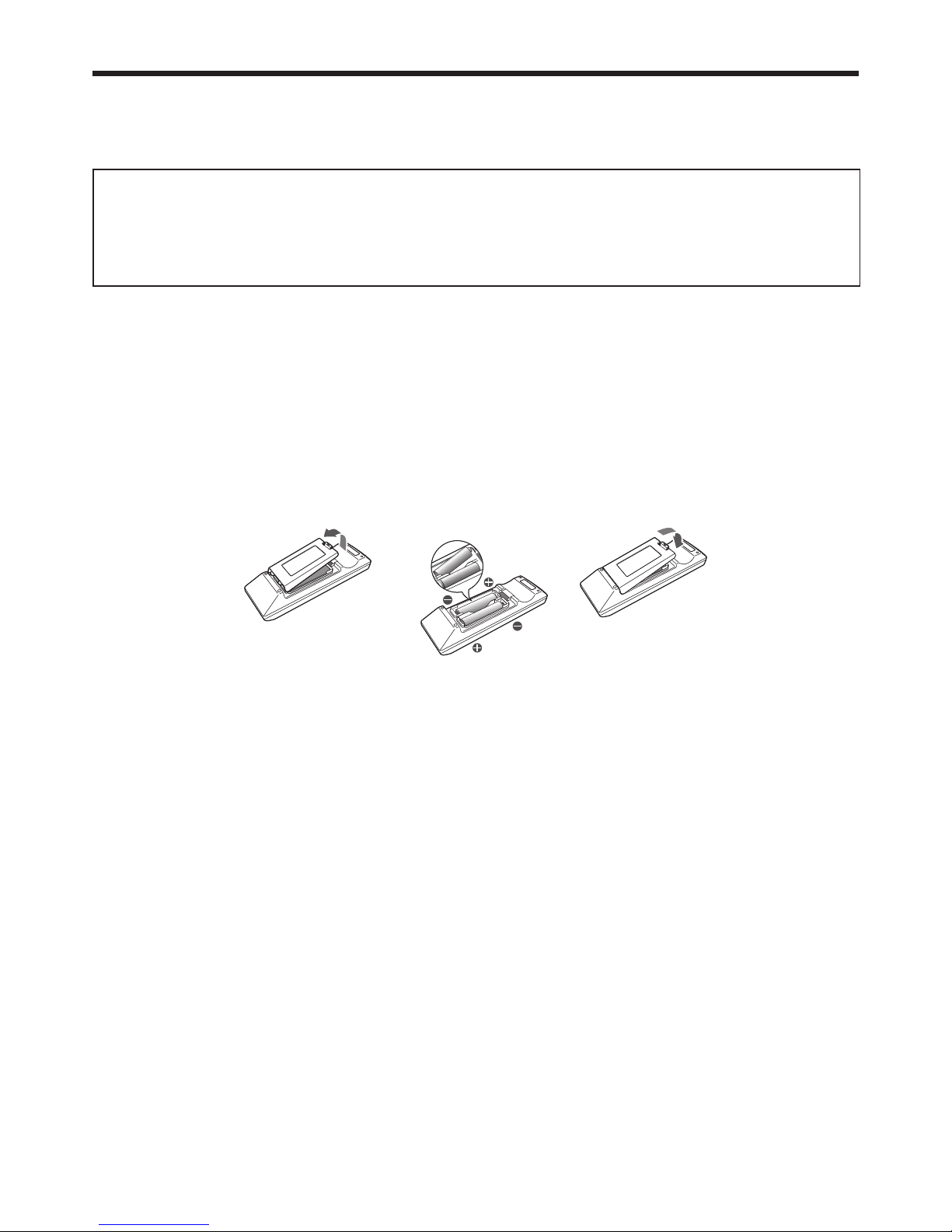
Battery installation
Use two (AA, R6) size batteries.
Inserting the batteries into the remote control
1. Remove the back cover of the remote control by pushing the battery compartment door in the direction of the
arrow.
2. Load the batteries making sure that they are positioned correctly (+ to +, and - to -).
• Load the batteries from - spring side, and make sure to set them tightly.
3. Replace the back cover.
Removing the batteries from the remote control
Remove the back cover of the remote control and take out the batteries.
Caution:
• Use of a battery of wrong type may cause explosion.
• Only Carbon-Zinc or Alkaline-Manganese Dioxide type batteries should be used.
• Dispose of used batteries according to your local regulations.
• Before you dispose of the batteries, insulate them by placing insulation tape on the positive (+) and negative (-)
terminals. If you dispose of the batteries together with other conductive objects such as a metal piece, they may
short out, resulting in fi re or explosion.
•
Batteries may explode if misused. Do not recharge, disassemble, or heat the batteries, or put them into fi re or water.
• Be sure to handle the batteries according to the instructions.
• Load the batteries with its positive (+) and negative (-) sides correctly oriented as indicated on the remote control.
• Keep batteries out of reach of children and pets. If children swallow the battery, see a doctor immediately.
• Remove the batteries, if the remote control is not used for a long time.
• Do not combine a new battery with an old one.
• If the solution of batteries comes in contact with your skin or clothes, rinse with water. If the solution comes in
contact with your eyes, rinse them with water and then consult your doctor.
• Do not carry or store the batteries together with metallic ballpoint pens, necklaces, coins, or hairpins. Otherwise,
they may short out, causing explosion or liquid leakage and resulting in fi re or injury.
• Do not store the batteries where they are exposed to direct sunlight or subjected to high temperature and high
humidity. High temperature and high humidity may cause corrosion or liquid leakage.
• Do not place the batteries or the battery-installed remote control in a place where temperature rises such as an
area exposed to direct sunlight, near a heat generating device, and near direct heat.
• The lifetime of the batteries is about 1 year. (It varies depending on the usage.)
• Do not drop, hit, or give impact to the remote control. Do not place a heavy object or step on the remote control.
Doing so may cause cracking of the internal board and other failures even if it doesn’t damage the remote control
in its appearance. Handle it with care.
EN-7
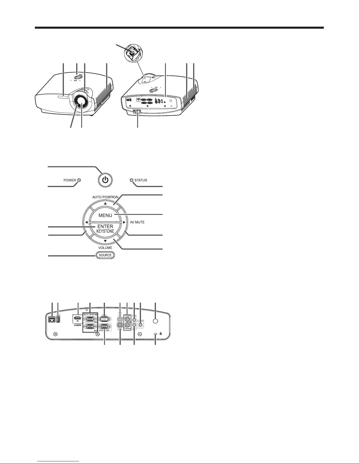
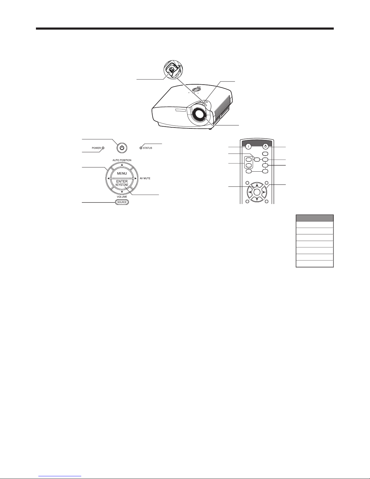
Overview
6105
1 3 4
11
9872
2
4
5
3
6
7
9
10
8
1
1 Remote control sensor (front)/
Intelligent glare sensor
2 Control area
3 Zoom ring
4 Air outlet grille
5 Focus ring
6 Lens
7 Terminal panel
8 Speaker
9 Air inlet grille
10 Power jack
11 LENS SHIFT dial
Control area
1 POWER button (ON/STANDBY)
The status is changed between ON and
STANDBY.
2 POWER indicator
3 ENTER/KEYSTONE button
4 button
5 SOURCE button
6 STATUS indicator
7 AUTO POSITION/ button
8 MENU button
9 AV MUTE/ button
10 VOLUME/ button
1 23 567
11 12 13 14
8 9 104
1 LAN terminal
2 USB-A terminal
3 HDMI IN terminal (HDMI 19-pin)
4 COMPUTER/COMPONENT VIDEO IN terminals
(1,2) (mini D-SUB 15-pin)
5 SERIAL terminal (D-SUB 9-pin male)
6 VIDEO IN terminal
7 AUDIO IN 3 terminals (L,R)
8 AUDIO IN 1 terminal (mini jack)
9 AUDIO OUT terminal (mini jack)
10 Remote control sensor (rear)
11 MONITOR OUT terminal (mini D-SUB 15-pin)
12 S-VIDEO IN terminal
13 AUDIO IN 2 terminal (mini jack)
14 Kensington Security Lock Standard connector
Terminal panel
Preparing your projector (continued)
EN-8
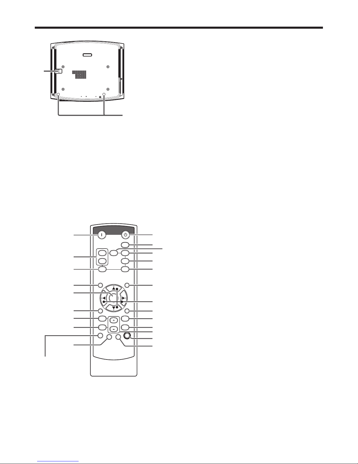
2
1
Preparing your projector (continued)
Bottom side
1 Lock bar (SECURITY ANCHOR)
• Attach a chain, etc. to this lock bar to anchor
the projector.
2 Adjustment feet
ON
AUTO POSITIION
USB VIEWERLAN DISP.
COMPUTER
STANDBY
MENU
KEYSTONE
MAGNIFY
COLOR.E
ASPECT
3D
ENTER
VOL
AV MUTE
VIDEO
HDMI1
2
S-VIDEO
FREEZE
E-Z/S
TIMER
TEST
PATTERN
SILENT
MODE
1
2
3
4
5
6
9
7
8
19
20
21
16
15
17
18
22
23
10
11
12
13
14
Remote control
1 ON button
2 COMPUTER 1, 2 buttons
3 LAN DISP. button
4 MENU button
5 ENTER button
6 3D button
7 KEYSTONE button
8 MAGNIFY button
9 TIMER button
10 STANDBY button
11 AUTO POSITION button
12 HDMI button
13 VIDEO button
14 S-VIDEO button
15 USB VIEWER button
16 ASPECT button
17 , , , buttons
18 COLOR. E (COLOR.ENHANCER) button
19 AV (Audio/Video) MUTE button
20 FREEZE button
21 + , - buttons
*1
22 SILENT MODE button
23 TEST PATTERN button
*1: The +, - buttons also function for KEYSTONE and MAGNIFY adjustment.
This model does not
have this function.
EN-9
Using the remote control
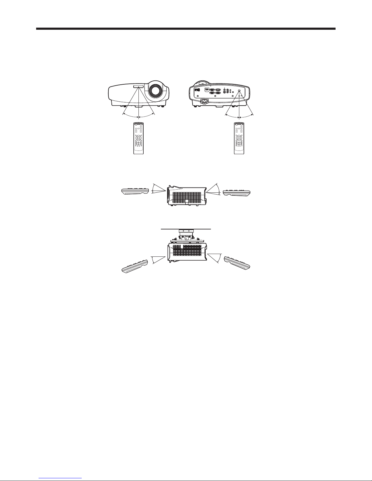
Operation range (of the remote control)
The maximum operation distance of the remote control is about 10 m (or about 32 feet) when the remote control is
pointed at the remote control sensor of the projector. When the remote control is pointed to the screen, the distance
from the remote control to the projector via the screen should be 5 m or less. However, the operation distance varies
depending on the type of the screen used.
Reception angle (horizontal)
About 30° About 30°About 30°
About 30°
Reception angle (vertical)
About 40°
About 30°
About 5°
About 5°
Reception angle (vertical), ceiling mount
About 40°
About 30°
Important:
• Do not expose the remote control sensor to direct sunlight or fl uorescent. Keep a distance at least 2 m (6.5 feet)
between the remote control sensor and the fl uorescent light to ensure correct operation of the remote control.
Inverted fl uorescent light, if located near the projector, may interfere the remote control.
• When you use the remote control too close to the remote control sensor, the remote control may not work
correctly.
EN-10
Setting up your projector
Before setting up
Before setting up the projector, check the operating environment.
If the environmental requirements are not satisfi ed, the projector may break down or fail.
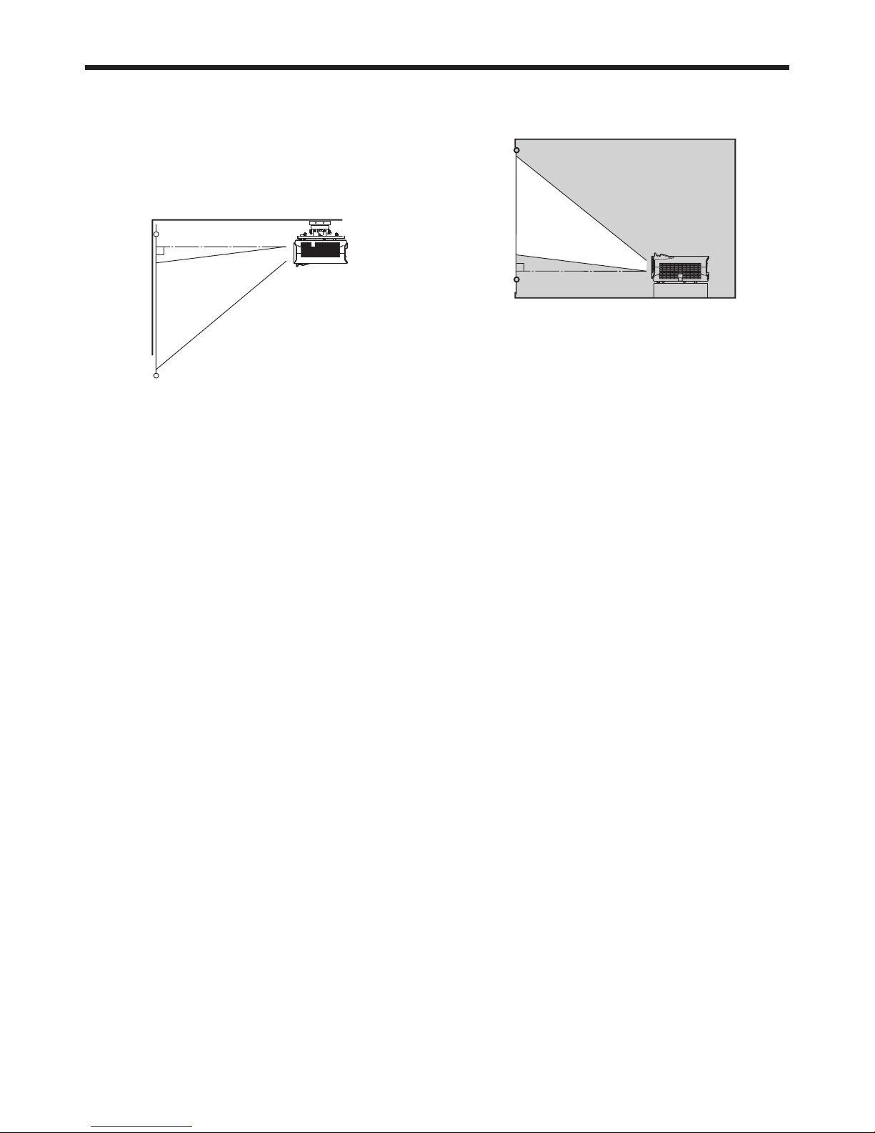
Setting up the screen
Install the screen perpendicularly to the projector. If the screen can not be installed in such a way, adjust the
projection angle of the projector. (See page 12.)
• Install the screen and projector so that the projector’s lens is placed at the same height and horizontal position of
the screen center.
• Do not install the screen where it is exposed to direct sunlight or lighting. Light directly refl ecting on the screen
makes the projected images whitish and hard to view.
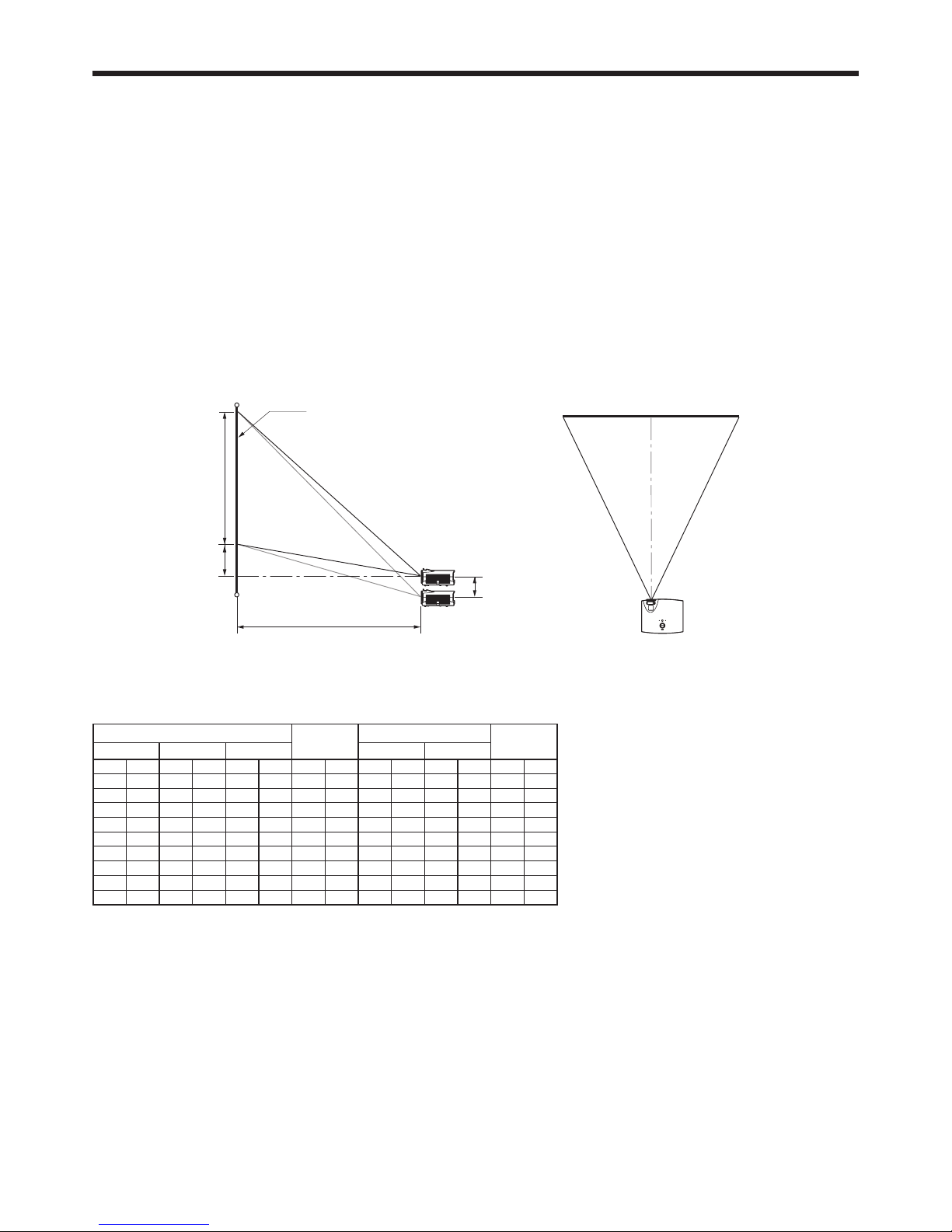
Screen size and projection distance
Refer to the following table to determine the screen size and projection distance.
• For the aspect ratio setting, see page 22.
• The fi gures in the tables are approximate and may be slightly different from the actual measurements.
• The lens shift height shows distances from the factory default position.
Screen width (SW)
Down side
Up side
Screen
Screen height (SH)Hd
H
L
Screen size (16:10)
Hd
Projection distance (L)
Lens shift
height (H)
Diagonal size
Width (SW) Height (SH)
Shortest (Wide)
Longest (Tele)
inch cm inch cm inch cm inch cm inch m inch m inch cm
40 102 34 86 21 54 2.6 7 49 1.2 76 1.9 3 8
60 152 51 129 32 81 4 10 74 1.9 114 2.9 5 12
80 203 68 172 42 108 5 13 99 2.5 153 3.9 6 16
100 254 85 215 53 135 7 17 124 3.2 191 4.9 8 20
120 305 102 258 64 162 8 20 149 3.8 230 5.8 10 24
150 381 127 323 79 202 10 25 187 4.7 288 7.3 12 30
200 508 170 431 106 269 13 33 250 6.3 384 9.8 16 40
250 635 212 538 132 337 16 42 312 7.9 - - 20 51
300 762 254 646 159 404 20 50 375 9.5 - - 24 61
EN-11
Setting up your projector (continued)
Screen size and projection distance (continued)
Screen width (SW)
Down side
Up side
Screen
Screen height (SH)Hd
H
L
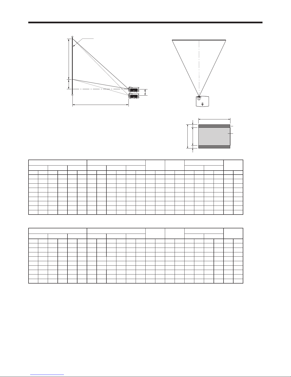
When the aspect ratio of the screen is 4:3
When the aspect ratio of the screen is 4:3, the positional relation between
the projected image and the screen is as shown on the right. Refer to the
following table for installation.
• When the aspect ratio of the image is 16:10 (WXGA)
Screen size (4:3) Size of the projected image (16:10)
Black space
(B)
Hd
Projection distance (L)
Lens shift
height (H)
Diagonal size
Width (SW) Height (SH)
Diagonal size
Width (W) Height (H)
Shortest (Wide)
Longest (Tele)
inch cm inch cm inch cm inch cm inch cm inch cm inch cm inch cm inch m inch m inch cm
40 102 32 81 24 61 38 96 32 81 20 51 2 5 4 11 46 1.2 71 1.8 3 8
60 152 48 122 36 91 57 144 48 122 30 76 3 8 7 17 70 1.8 108 2.7 5 11
80 203 64 163 48 122 75 192 64 163 40 102 4 10 9 23 93 2.4 144 3.7 6 15
100 254 80 203 60 152 94 240 80 203 50 127 5 13 11 28 117 3.0 180 4.6 8 19
120 305 96 244 72 183 113 288 96 244 60 152 6 15 13 34 141 3.6 217 5.5 9 23
150 381 120 305 90 229 142 359 120 305 75 191 8 19 17 43 176 4.5 271 6.9 11 29
200 508 160 406 120 305 189 479 160 406 100 254 10 25 22 57 235 6.0 362 9.2 15 38
250 635 200 508 150 381 236 599 200 508 125 318 13 32 28 71 295 7.5 - - 19 48
300 762 240 610 180 457 283 719 240 610 150 381 15 38 34 85 354 9.0 - - 23 57
• When the aspect ratio of the image is 16:9
Screen size (4:3) Size of the projected image (16:9)
Black space
(B)
Hd
Projection distance (L)
Lens shift
height (H)
Diagonal size
Width (SW) Height (SH)
Diagonal size
Width (W) Height (H)
Shortest (Wide)
Longest (Tele)
inch cm inch cm inch cm inch cm inch cm inch cm inch cm inch cm inch m inch m inch cm
40 102 32 81 24 61 37 93 32 81 18 46 3 8 5 13 46 1.2 71 1.8 3 8
60 152 48 122 36 91 55 140 48 122 27 69 5 11 8 20 70 1.8 108 2.7 5 11
80 203 64 163 48 122 73 187 64 163 36 91 6 15 10 27 93 2.4 144 3.7 6 15
100 254 80 203 60 152 92 233 80 203 45 114 8 19 13 33 117 3.0 180 4.6 8 19
120 305 96 244 72 183 110 280 96 244 54 137 9 23 16 40 141 3.6 217 5.5 9 23
150 381 120 305 90 229 138 350 120 305 68 171 11 29 20 50 176 4.5 271 6.9 11 29
200 508 160 406 120 305 184 466 160 406 90 229 15 38 26 66 235 6.0 362 9.2 15 38
250 635 200 508 150 381 229 583 200 508 113 286 19 48 33 83 295 7.5 - - 19 48
300 762 240 610 180 457 275 699 240 610 135 343 23 57 39 100 354 9.0 - - 23 57
Screen (4:3)
Image (16:10 / 16:9)
BB
H
SH
SW (=W)
EN-12
Changing the AUTO POWER OFF
setting
The AUTO POWER OFF function of this projector is
enabled by default.
Change the AUTO POWER OFF setting as necessary.
(See page 29.)
To change the AUTO POWER OFF setting:
(See page 26 for menu setting.)
1. Display the INSTALLATION menu.
2. Select AUTO POWER OFF by pressing the or
button.
AUTO POWER OFF 5min
3. Select your desired item by pressing the or
button.
Important:
• This function does not work when the input source
is LAN DISPLAY or USBVIEWER.
• The AUTO POWER OFF function does not work
during AV MUTE.
• While the intelligent glare sensor is detecting an
object, AUTO POWER OFF doesn't work. (When
the intelligent glare sensor stops detecting, the
projector turns off.)
Setting HIGH ALTITUDE MODE
• Set HIGH ALTITUDE MODE in the FEATURE menu
according to the altitude at which you use the
projector. The default setting is STANDARD.
• Select STANDARD when using the projector at an
altitude from 0 to 1500 meters.
• Select HIGH ALTITUDE when using the projector at
an altitude from 1500 to 2700 meters.
Important:
• If you select STANDARD when using the projector
at an altitude higher than 1500 meters, the
projector may break down or fail.
• When you use the projector in the HIGH ALTITUDE
mode, only fl oor installation and ceiling installation
are allowed.
(See page 26 for menu setting.)
1. Display the FEATURE menu.
2. Select HIGH ALTITUDE MODE by pressing the
or button.
HIGH ALTITUDE MODE
STANDARD
3. Press the ENTER button.
HIGH ALTITUDE MODE
HIGH ALTITUDE MODE
STANDARD
4. Select STANDARD or HIGH ALTITUDE by
pressing the or button.
5. Press the ENTER button.
Setting IMAGE REVERSE
Set IMAGE REVERSE in the INSTALLATION menu
according to the orientation of the projector. The
default setting is OFF.
• Select OFF for the combination of fl oor installation
and front projection.
• Select MIRROR INVERT for the combination of
ceiling installation and front projection.
• Select MIRROR for the combination of fl oor
installation and rear projection.
• Select INVERT for the combination of ceiling
installation and rear projection.
(See page 26 for menu setting.)
1. Display the INSTALLATION menu.
2. Select IMAGE REVERSE by pressing the or
button.
OFF
IMAGE REVERSE
3. Select OFF, MIRROR, INVERT or MIRROR INVERT
by pressing the or button.
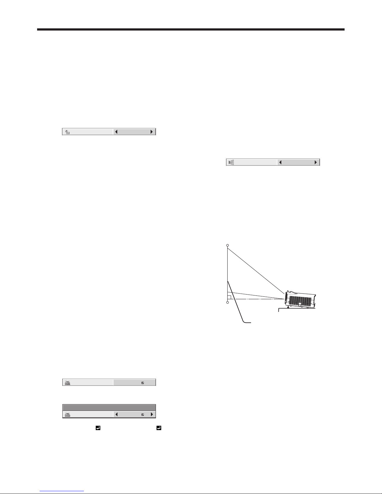
Correcting skewed or distorted
image
For the best projection, project images on a fl at screen
installed at 90 degrees to the fl oor. If necessary, tilt the
projector using the two adjustment feet on the bottom
of the projector.
Adjustment feet
Screen
1. Tilt up the projector to the appropriate angle.
2. Rotate the adjustment feet for fi ne adjustment.
Important:
• Don’t transport the projector with its adjustment
feet extended. Otherwise the adjustment feet may
be damaged.
When fi ne streaks are seen on
projected images
This is due to interference with the screen surface and
is not a malfunction. Replace the screen or displace
the focus a little.
Setting up your projector (continued)
EN-13
Setting up your projector (continued)
Adjusting the position of the
projected image
To adjust the position of the projected image on the
screen, use the LENS SHIFT dial.
1. Rotate the LENS SHIFT dial inside the top cover of
the projector to adjust the image position.
• Rotating the dial clockwise (or counterclockwise
for a ceiling-mount projector) moves the image
up.
• Rotating the dial counterclockwise (or clockwise
for a ceiling-mount projector) moves the image
down.
• Be careful not to be caught in the opening in the
lens while the lens is moving.
• While the lens shift is working, the screen may
fl icker.
• Projected images may become distorted, have
decreased resolution, or have shadows at their
corners if they are positioned close to the top or
bottom.
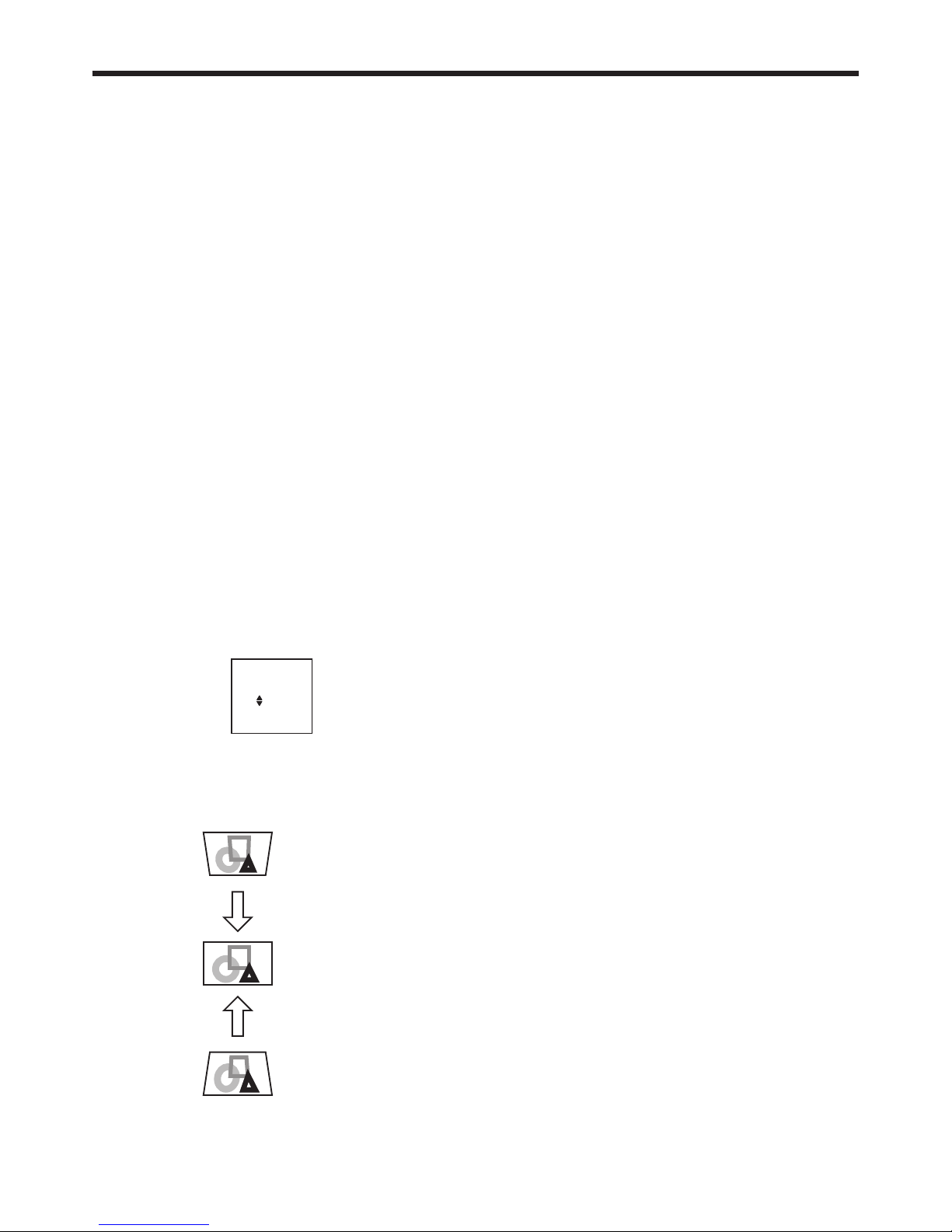
When projected images are
distorted to a trapezoid
When AUTO KEYSTONE in the INSTALLATION menu
is set to ON, this projector automatically corrects
vertical keystone distortion. For fi ne adjustment, press
the KEYSTONE button on the projector or the remote
control to display Keystone, and adjust the image by
pressing the , button (or +, - button on the remote
control).
KEYSTONE
0
KEYSTONE menu
You can correct the distortion vertically focusing on
the screen center.
In the following cases:
Press the
or - button.
Press the
or + button.
Important:
• The automatic keystone adjustment may not
be carried out correctly because of the ambient
temperature and the installation conditions of the
projector and the screen. In such cases, correct the
keystone manually.
• When the projector is projecting images where
acceleration is present, such as in a vehicle and
aircraft, the automatic keystone adjustment may
not function correctly. In such a case, set AUTO
KEYSTONE in the INSTALLATION menu to OFF and
correct the keystone manually.
• When the KEYSTONE-mode adjustment is carried
out, the adjustment value is indicated. Note that
this value doesn’t mean a projection angle.
• When the KEYSTONE-mode adjustment takes
effect, the resolution decreases. In addition, stripes
may appear or straight lines may bend in images
with complicated patterns. They are not due to
product malfunctions.
• When the KEYSTONE-mode adjustment is
performed, the displayed image may be distorted.
• Noise may appear on the screen during the
KEYSTONE-mode adjustment because of the type
of the video signal being projected and the setting
values of the KEYSTONE-mode adjustment. In
such cases, set the KEYSTONE-mode adjustment
values in the range where the image is displayed
without noise.
• When the KEYSTONE-mode adjustment is
performed, the menu display is distorted. To relieve
such symptom, set the MENU POSITION to center.
Intelligent glare sensor:
To prevent discomfort feeling to the eyes caused
by seeing the illuminating light source through the
lens, the intelligent glare sensor detects a person
who stands in front of the projector and mutes the
projected images automatically.
• The intelligent glare sensor detects an object
placed in front of the lens and shuts off the screen.
Therefore, do not place any object within 50 cm
from the front of the sensor.
• The sensor may detect a transparent board.
• To cancel muting temporarily, press the POWER
button on the projector or the ON button on the
remote control.
EN-14
Setting up your projector (continued)
Front projection, ceiling mounting
For ceiling mounting, you need the ceiling mount
kit designed for this projector. Ask a specialist for
installation. For details, consult your dealer.
• The warranty on this projector does not cover any
damage caused by use of any non-recommended
ceiling mount kit or installation of the ceiling mount
kit in an improper location.
• When using the projector mounted on the ceiling,
set IMAGE REVERSE in the INSTALLATION menu
to MIRROR INVERT. See page 29.
• When the projector is mounted on the ceiling,
images may appear darker than those projected in
the case of tabletop mounting. This isn’t a product
malfunction.
• Ask your installation specialist to provide a breaker.
When you do not use the projector, be sure to shut
down the main power by the breaker.
• Do not install the projector where the exhaust vents
are exposed to air emitted by an air conditioning.
Such installation may cause a breakdown.
• Do not install the projector near a fi re alarm
because it emits hot air from its exhaust vents.
Caution:
• Installation must be done by a qualifi ed
professional.
When the projector is installed on the ceiling using
the ceiling mount kit, it is recommended to hold
the mount kit and the projector using metal bars
or wires in addition to the mount kit fi xing screws
to prevent the projector from falling due to an
earthquake or other cause. For that purpose, use
metal bars, wires, or screws that bear a load of at
least 70 kgf. When using metal wires, secure one
end to the adjustment foot of the projector and the
other end to the mount kit. In this case, make sure
that no electrical current is fl owing in the mount kit
due to current leakage or other cause.
Rear projection
Ask a specialist for installation. For details, consult
your dealer.
• For rear projection, set IMAGE REVERSE in the
INSTALLATION menu to MIRROR. See page 29.
Caution:
• Placing the projector directly on a carpet impairs
ventilation by the fans, causing damage or failure.
Put a hard board under the projector to facilitate
ventilation.
• Place the projector at least 50 cm (or 20 inches)
away from the wall to prevent the air inlet grille and
the air outlet grilles that emit hot air from being
blocked.
• Do not use the projector in the following locations
and manners, which may cause fi re or electric
shock.
• In a dusty or humid place.
• Near a heater.
• In an oily, smoky, or damp place such as a kitchen.
• In direct sunlight.
• Where the temperature rises high, such as in a
closed car.
• Where the temperature is lower than +41ºF (or
+5ºC) or higher than +95ºF (or +35ºC).
• For use in the HIGH ALTITUDE mode
• In other than fl oor installation and ceiling
installation.
• Keep foliage plants and pets away from the
projector. The temperature around the exhaust
vents and that of the cabinet on the top of the
exhaust vents become high. Take special care for
small children.
Important:
• We don’t recommend using the projector at an
altitude of 2700 meters or higher (When using
the product at an altitude of 1500 to 2700 meters
above the sea level, set the HIGH ALTITUDE MODE
to HIGH ALTITUDE.). Use at an altitude of 2700
meters or higher may affect the projector’s life.
EN-15
Basic connections
This projector can be connected with various devices such as a VCR, video camera, videodisc player, and personal
computer that have analog RGB output connectors.
Important:
• Make sure that the connected device is turned off before starting connection.
• Plug in the power cords of the projector and the connected devices fi rmly. When unplugging, hold and pull the
plug. Do not pull the cord.
• When the projector and the connected devices are located too close to each other, the projected image may be
affected by their interference.
• See the owner’s guide of each device for details about its connections.
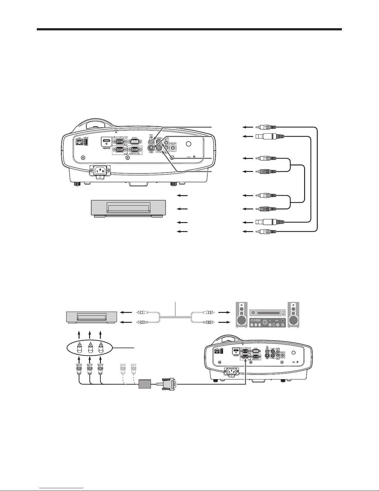
Projector + AV device
Audio cable (option)
VCR, etc.
VIDEO
S-VIDEO
S-video cable (option)
Video cable (option)
AUDIO IN-3L
AUDIO IN-3R
To audio output (L)
To audio output (R)
To video output
To S-Video output
Important:
• Match the colors of the video and audio plugs on the Audio cable with those of the terminals.
• Speaker output is mono.
Projector + DVD player or HDTV decoder
Some DVD players have an output connector for 3-line fi tting (Y, CB, CR). When connecting such DVD player with this
projector, use the COMPUTER/COMPONENT VIDEO IN terminal.
BRG
Audio cable (option)
DVD player or HDTV decoder
To audio output
BNC - RCA connector (option)
No connection
COMPUTER/COMPONENT VIDEO IN
Mini D-SUB 15-pin - BNC conversion
cable (option)
Important:
• The terminal’s names Y, PB, and PR are given as examples of when a HDTV decoder is connected.
• The terminal’s names vary depending on the connected devices.
• Use a mini D-SUB 15-pin - BNC conversion cable for connection.
• Image may not be projected correctly with some DVD players.
• When connecting a HDTV decoder having RGB output terminals, set COMPUTER INPUT to RGB in the SIGNAL
menu.
EN-16
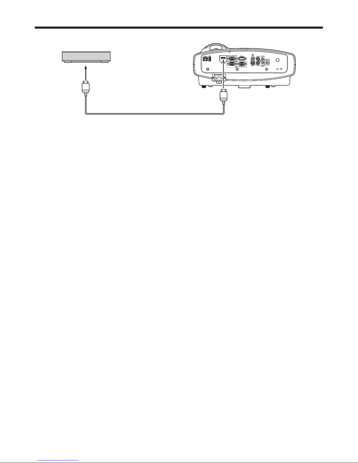
Basic connections (continued)
Connection (for video equipment having an HDMI terminal)
Equipment having an
HDMI terminal
To HDMI terminal
HDMI
HDMI (with HDMI logo) cable (option)
Important:
• Use a commercially available HDMI (with HDMI logo) cable.
• You don’t have to connect any cable for audio input. You can input video and audio using an HDMI cable only.
• When HDMI audio isn’t output, it may be output by turning off the power of the video equipment with the projector
and the video equipment connected to each other and then turning back on the power.
• Some cables may not be connected correctly depending on the size and shape of their connectors.
When you connect this projector and a Digital device (such as a DVD player) via the HDMI terminal, black
color may appear dark and deep, depending on the type of the connected device.
• This depends on the black level setting of the connected device. There are two kinds of methods to digitally
transfer image data, in which different black level settings are employed respectively. Therefore, the specifi cations
of the signals output from DVD players differ, depending on the type of the digital data transfer method they use.
• Some DVD players are provided with a function to switch the methods to output digital signals. When your DVD
player is provided with such function, set it as follows.
EXPAND or ENHANCED NORMAL
• See the users guide of your DVD player for details.
• When your digital device does not have such function, set INPUT LEVEL to ENHANCED in the ADVANCED MENU
of the IMAGE menu of this projector, or adjust the black color by viewing the image.
EN-17
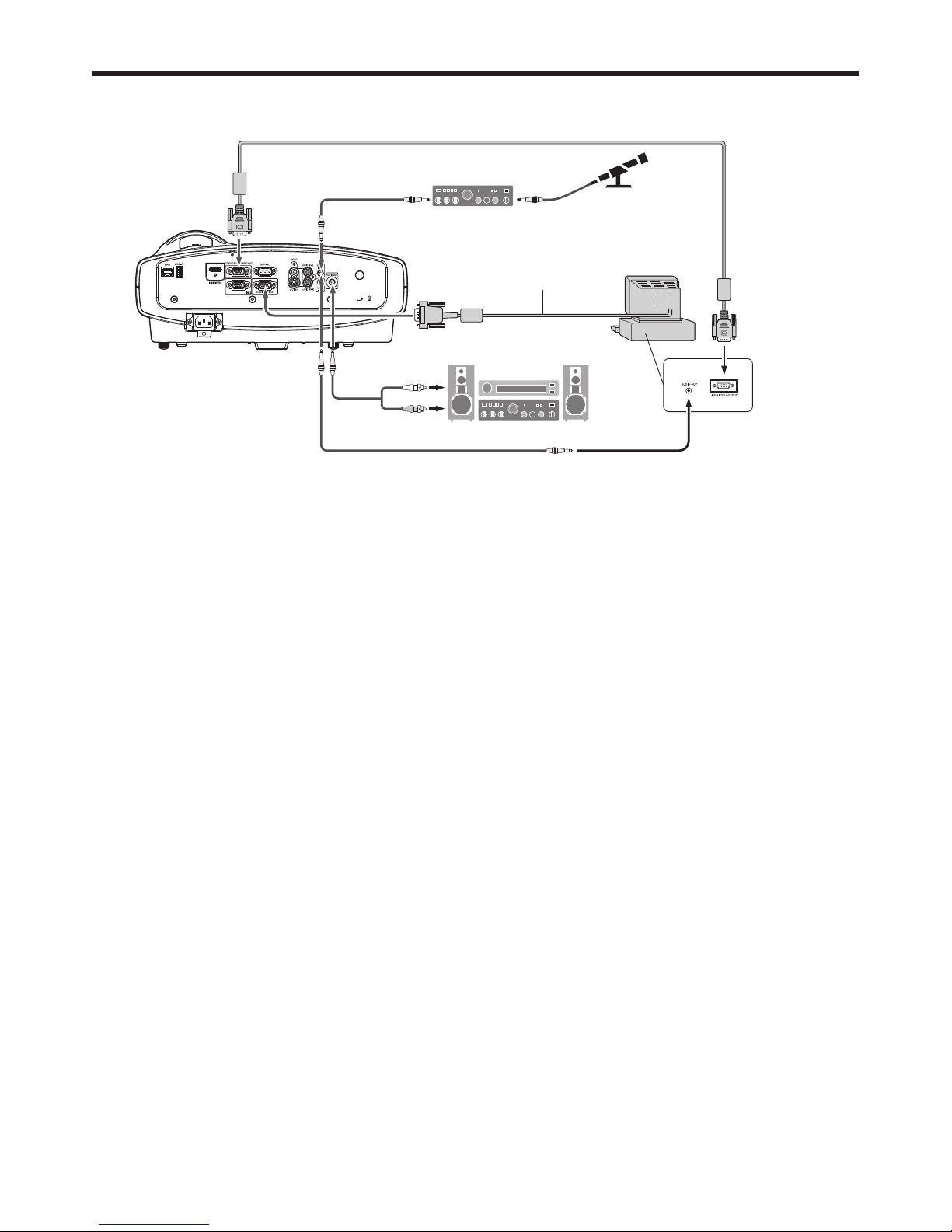
Projector + Computer
For computer with Mini D-SUB
COMPUTER/
COMPONENT
VIDEO IN
MONITOR OUT
Audio cable
(option)
PC audio cable (option)
PC audio cable
(option)
To PC audio output
To monitor port
AUDIO IN-1
or IN-2
AUDIO IN-1
or IN-2
AUDIO
OUT
Necessary when outputting to both
a PC monitor and the projector.
Computer cable
Microphone amplifi er
(option)
Microphone
(option)
Computer cable (option)
Computer
For analog connection:
1. Connect one end of the supplied computer cable to the COMPUTER/COMPONENT VIDEO IN terminal (1, 2) of the
projector.
2. Connect the other end of the computer cable to the monitor port of the computer.
For monitor connection:
Connect the computer cable from the monitor to the MONITOR OUT terminal of the projector.
• Images may not be displayed correctly depending on the type of the input signal. See the instruction manual of
the monitor.
• Signals are coming from the COMPUTER/COMPONENT VIDEO IN-1 terminal of the projector.
• When the STANDBY MODE in the Installation menu is set to STANDARD, the MONITOR OUT terminal outputs
signals during power standby.
Important:
• When you use a longer computer cable instead of the provided cable, the image may not be projected correctly.
• Some computers require additional connectors or analog RGB output adapters to be connected with this
projector. Contact your dealer for further information.
• This projector uses stereo mini jack for its audio input. Check the type of the audio output terminal of the
connected computer and prepare a proper cable for connection. Some computers don’t have the audio output
terminal.
• Speaker output is mono.
• When the audio cable is connected to the AUDIO OUT terminal, the speaker output is muted.
• The audio output can be available during power standby according to the setting. (See page 28.)
• The audio signals for AUDIO IN-1 and AUDIO IN-2 can be output simultaneously according to the setting. (See
page 28.)
For Mac computers
• If your Mac computer has no video port, a monitor output adapter is required. Contact your dealer for further
information.
• Some Mac computers require a Mac adapter for the computer cable for connection with this projector. Contact
your dealer for further information.
About DDC
The COMPUTER/COMPONENT VIDEO IN terminal (1, 2) of this projector complies with the DDC 1/2B standard.
When a computer supporting this standard is connected to this terminal, the computer will automatically load the
information from this projector and prepare for output of appropriate images.
• After connecting a computer supporting this standard to this terminal, plug the power cord of the projector in the
wall outlet fi rst, and then boot up the computer.
Basic connections (continued)
EN-18
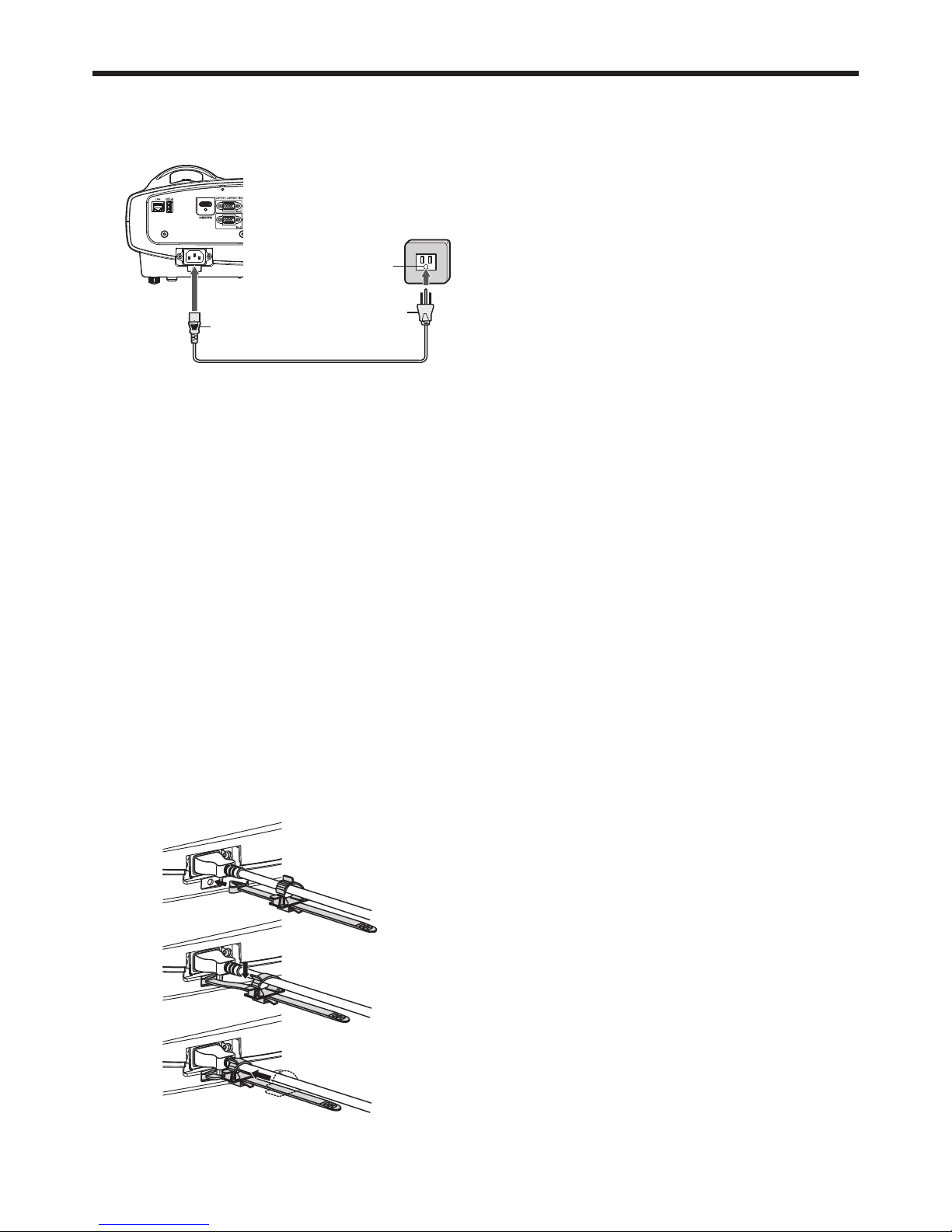
Plugging the power cord
• In order to ensure the safety in case of trouble with the projector, use an electrical outlet having an earth leakage
breaker to supply the power to the projector. If you do not have such outlet, ask your dealer to install it.
1. Plug the attached power cord into the power cord
inlet of this projector.
2. Plug the other end of the power cord into a power
outlet.
Warning:
• One of power cords for the U.S., Europe, U.K., Australia and South Korea is provided appropriately.
• This projector uses the power plug of 3-pin grounding type. Do not take away the grounding pin from the power
plug. If the power plug doesn’t fi t your wall outlet, ask an electrician to change the wall outlet.
• In case that the power cord for the U.S. is provided with this projector, never connect this cord to any outlet
or power supply using other voltages or frequencies than rated. If you want to use a power supply using other
voltage than rated, prepare an appropriate power cord separately.
• Use 100-240 V AC 50/60 Hz to prevent fi re or electric shock.
• Do not place any objects on the power cord or do not place the projector near heat sources to prevent damage to
the power cord. If the power cord should be damaged, contact your dealer for replacement because it may cause
fi re or electric shock.
• Do not modify or alter the power cord. If the power cord is modifi ed or altered, it may cause fi re or electric shock.
Caution:
• Plug in the power cord fi rmly. When unplugging, hold and pull the power plug, not the power cord.
• Do not plug in or out the power cord with your hand wet. It may cause electric shock.
• When you move the projector, turn off the power, unplug the power cord from the wall outlet, and then remove the
connected cords. Otherwise, the power cord may be damaged, resulting in fi re or electric shock.
• If dust or metallic substance is on or around the pins of the power plug, unplug the power cord and clean it using
a dry cloth. If you continue to use the projector without cleaning, it may result in fi re or electric shock. Clean the
power plug periodically at least once a year.
• Be sure to unplug the power cord from the wall outlet if the projector will not be used for a long period of time.
Otherwise, it may cause fi re.
Basic connections (continued)
2
1
Power cord (example)
Earthing
terminal
Attaching the power cord holder:
To reduce the risk of accidental disconnection of the power
cord from the projector, attach the supplied power cord holder
to hold it.
Important:
• Once the power cord holder is attached to the projector, it
cannot be removed.
• If you apply an excessive force, the power cord holder may
be damaged.
1. Insert the tip of the power cord holder into the slot with the
clamper facing toward the power cord.
2. Put the power cord in the clamper, and push the clamper in
the direction of the arrow to lock it.
3. Slide the clamper toward the plug.
EN-19
Projecting images
Preparation:
• Remove the lens cap.
ON
AUTO POSITIION
USB VIEWERLAN DISP.
COMPUTER
STANDBY
MENU
COLOR.E
ASPECT
3D
ENTER
VIDEO
HDMI1
2
S-VIDEO
COMPUTER 1, 2 buttons
POWER indicator
LENS SHIFT dial
STATUS indicator
ENTER button
, , , buttons
POWER button
(ON/STANDBY)
, , , buttons
ENTER button
SOURCE button
ON button
HDMI button
STANDBY button
Zoom ring
Focus ring
VIDEO button
S-VIDEO button
1. Confi rm the POWER indicator lights up red.
2. Turn on the power of the connected devices.
3. Press the POWER button.
• It may take a few seconds for the light source to light up.
• Do not cover the lens with the lens cap while the light source is on.
• After the POWER button is pressed, the image may fl icker before the light source becomes
stable. This is not a product malfunction.
4. Adjust the focus by turning the focus ring.
• You are recommended to adjust the focus at the screen center.
5. Select an input source.
• Press the SOURCE button on the projector or the COMPUTER (1 or 2), HDMI, VIDEO or S-VIDEO button on the
remote control that is corresponding to the terminal in use.
• When the SOURCE button is pressed, the SOURCE dialog shown right appears. Press the or button to
select an input and press the ENTER button.
• The projector automatically selects the appropriate signal format. The selected signal format is displayed on
the screen.
• You cannot change the input source while the menu is being displayed.
• Though it may take some time before an image is displayed on the screen depending on the type of the input
signal, such symptom is not a malfunction.
• Images may not be projected in the correct position, depending on the type of the input signal. In such a case,
press the AUTO POSITION button. (The AUTO POSITION only works when the input is COMPUTER (1 or 2).)
(See page 21.)
• When COMPUTER 1 or COMPUTER 2 is chosen as the source, images supplied from the computer may
fl icker. Press the or button on the remote control to reduce fl icker, if it occurs. (Fine adjustment)
6. Adjust the image size by turning the zoom ring.
7. Adjust the vertical position of the displayed image by turning the LENS SHIFT dial.
• If necessary, adjust the focus and zoom again.
8.
Adjust the position of the projector so that the projector and the screen are perpendicular to each other. (See page 10.)
•
When the projector cannot be positioned perpendicularly to the screen, adjust the projection angle. (See page 12.)
Basic operation
SOURCE
COMPUTER1
COMPUTER2
HDMI
VIDEO
S-VIDEO
LAN DISPLAY
USB VIEWER
EN-20
Basic operation (continued)
To stop projecting:
9. Press the POWER button.
• A confi rmation message is displayed.
• To cancel the procedure, leave the projector for a while or press any button except the POWER button.
10. Press the POWER button again.
• The light goes out and the projector goes into a standby mode. In this standby mode, the STATUS indicator
may blink green about 1 second and then go out.
11. Unplug the power cord from the outlet.
• The POWER indicator will go out. It may take about a half minute for the POWER indicator to go out.
• If necessary, disconnect the cables from the computer after unplugging the power cord.
Important:
• Before carrying the projector, rotate the focus ring and zoom ring to adjust the lens to the shortest. This prevents
the possible damages of the lens.
Direct Power OFF
You can turn off this projector just by unplugging the power cord without pressing the POWER button.
• Before shutting down the projector, be sure to close the menu screen. If you shut down the projector without
closing the menu, the setting data of the menu may not be saved.
• Don’t shut down the projector while you are changing the NETWORK menu settings or projector's settings via
network connection.
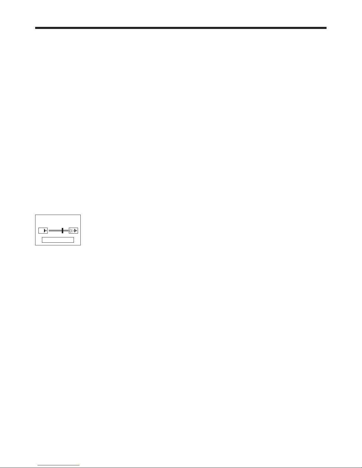
Volume from the speaker
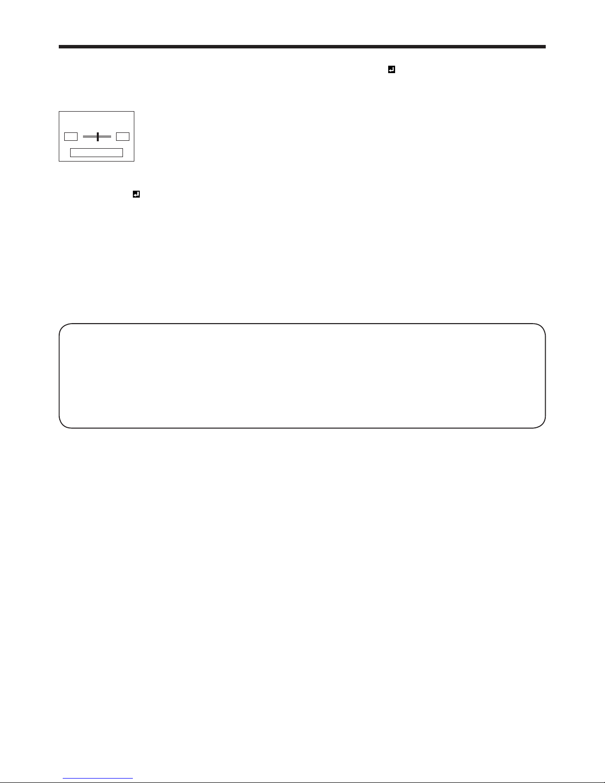
Press the VOLUME + or - button on the remote control or VOLUME button on the projector. The volume control bar
will appear on the screen. Press the VOLUME +, -, or button while the volume control bar is displayed to adjust
the volume.
• The volume control bar will also appear by pressing the ENTER button while the balance control bar is displayed.
VOLUME 16
ENTER : BALANCE
• The volume control bar will disappear about 10 seconds after the VOLUME button is released.
• The VOLUME buttons don’t function while the menu selection bar or the menu is being displayed.
• When a high-level audio signal, such as a DVD audio signal, is supplied to the AUDIO IN terminals, the output
from the speaker may be distorted.
• When the audio cable is connected to the AUDIO OUT terminal, the speaker output is muted.
• The volume of the audio from the AUDIO OUT terminal is also changed by pressing the VOLUME buttons.
• The VOLUME value varies within the range between 0 and 21, and the same value is applied during projection and
power standby.
You can change the volume during power standby by pressing VOLUME + or - button after the following setting is
done.
(See page 26 for menu setting.)
1. Display the INSTALLATION menu.
2. Select VOLUME ADJUSTMENT by pressing the or button.
3. Select PROJECTION AND STANDBY by pressing the or button.
4. Set STANDBY MODE to STANDARD. (See page 28.)
EN-21
Mix balance
You can change the volume balance between AUDIO1 and AUDIO2. Select MIX for AUDIO INPUT (PROJECTION)
or AUDIO INPUT (STANDBY) in the INSTALLATION menu and press the ENTER button. The balance control bar will
appear on the screen. Press the VOLUME +, -, or button while the balance control bar is displayed to adjust the
volume balance between AUDIO1 and AUDIO2.
IN 1 IN 2
BALANCE 0
ENTER : VOLUME
• The balance control bar will disappear about 10 seconds after the ENTER button is released.
• The balance control bar will also appear by pressing the ENTER button while the volume control bar is displayed
only when MIX is selected for AUDIO INPUT (PROJECTION) in the INSTALLATION menu.
• The volume balance between AUDIO1 and AUDIO2 cannot be changed during power standby.
• The BALANCE value varies within the range between -10 and 10, and the same value is applied during projection
and power standby.
Blanking the screen temporarily (AV MUTE)
The video and audio signals are temporarily muted when the AV MUTE button is pressed. You will hear an operating
sound inside the projector. To cancel muting, press the AV MUTE button again.
• The audio from the AUDIO OUT terminal is also muted by pressing the AV MUTE button.
• Mute can not be disabled by AV MUTE button while Intelligent glare sensor is working.
• The AUTO POWER OFF function does not work during AV MUTE.
AUTO POSITION button
When the image supplied from the computer is displaced, carry out the following procedure.
1. Project a bright image containing as many texts and characters as possible.
2. When the screen saver has been enabled, disable it.
3. Press the AUTO POSITION button.
The projector automatically makes optimum positional settings for the input signal.
• If the projected image is still displaced even after pressing the AUTO POSITION button several times, refer to
the procedure to adjust computer images. (See pages 37 and 38.)
• When you carry out this procedure with a dark image, the image may be displaced.
When connecting to a laptop computer:
When the projector is connected to a laptop computer, images may not be projected in some cases. In such cases,
set the computer so that it can output signals externally. The setting procedure varies depending on the type of the
computer. See the instruction manual of your computer.
Example of the setting procedure for external output
Press the [Fn] key and any of the keys [F1] to [F12] at the same time. (The key to be pressed depends on the type of
the computer you use.)
Setting of the resolution
If the resolution of the computer doesn’t match with that of the projector, projected images may be obscured. Ensure
that their resolutions are the same (see pages 72 and 73). For the method to change the output resolution of the
computer, contact the manufacturer of the computer.
Basic operation (continued)
EN-22
Setting the aspect ratio
You can change the aspect ratio of the input video signal (or the ratio of width to height of the image). Change the
setting according to the type of the screen to be used or your preference.
How to change the settings:
With the remote control:
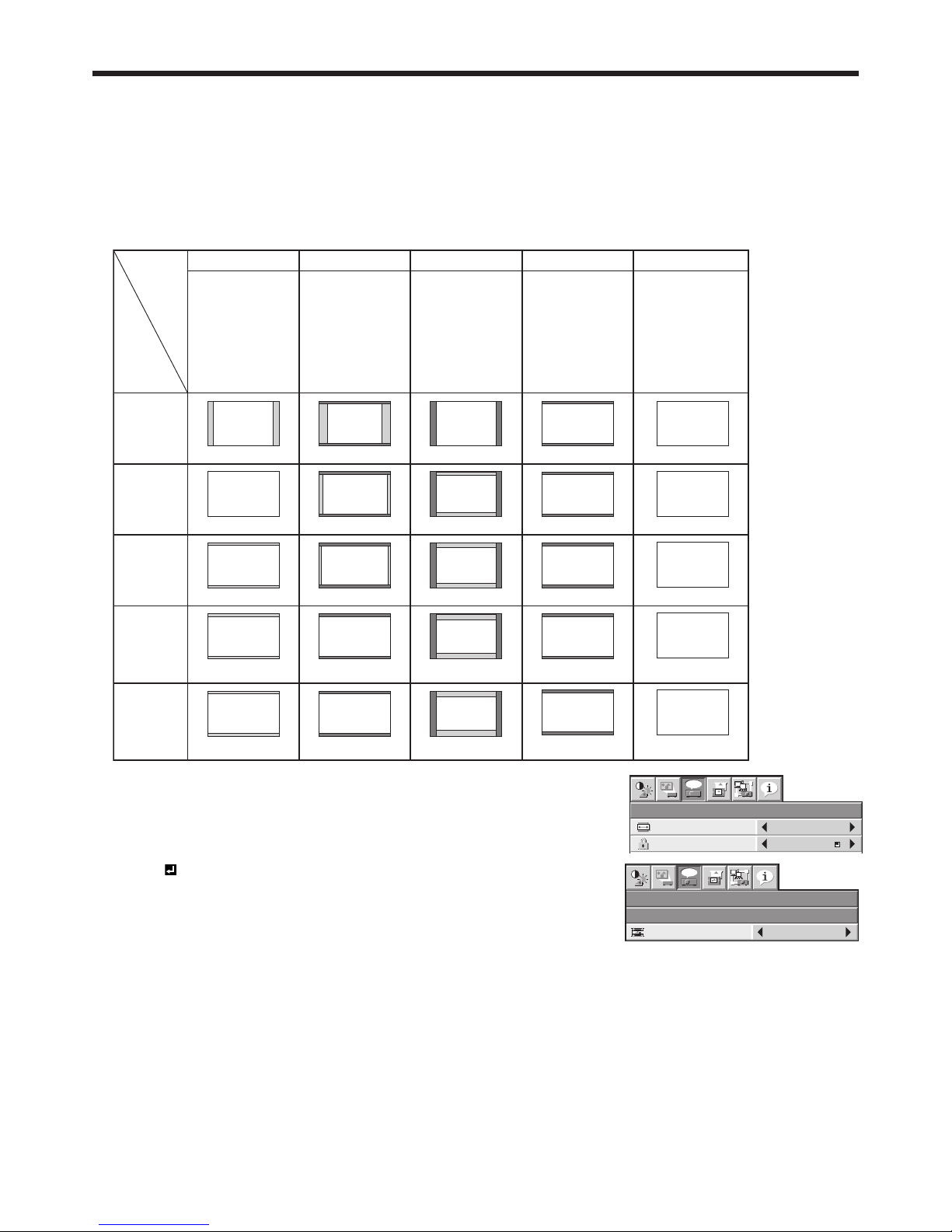
1. Press the ASPECT button.
• Every time the ASPECT button is pressed, the aspect mode changes from NORMAL (FULL) to NORMAL (16:9),
to NORMAL (4:3), to 16:9, to FULL, and back to NORMAL (FULL).
• The following table shows the image display patterns depending on the settings.
4:3 signal,
XGA signal
(1024 x 768),
etc.
WXGA signal
1280 x 800
(16:10)
WXGA signal
1280 x 768
(16:9.6)
WXGA signal
1360 x 768
(16:9.04)
16:9 signal
and
WXGA signal
1366 x 768
16:10
NORMAL (FULL)
Input signal
Setting
NORMAL (16:9) NORMAL (4:3) 16:9
FULL
Input video signal is
displayed at the max
height (800 pixels) or
max width (1280
pixels) of the panel
while its aspect ratio
is maintained.
Select this setting
when using a 16:9
screen.
Select this setting
when using a 4:3
screen.
Regardless of the type
of input signal, image
is displayed at 16:9
aspect ratio (1280 x
720 pixels). Select to
expand squeezed (or
horizontally
compressed) images
such as DVD images
to 16:9.
Regardless of the type
of input signal, image
is displayed at the full
panel size (1280 x 800
pixels).
4:3
1066 x 800
16:9.6
1280 x 768
16:9.04
1280 x 720
16:9
1280 x 720
16:10
960 x 720
16:9.6
1200 x 720
16:9.04
1280 x 720
16:9
1280 x 720
4:3
1066 x 800
16:9.6
1066 x 640
16:9.04
1066 x 602
16:9
1066 x 600
16:9
1280 x 720
16:10
16:9
1280 x 720
16:9
16:9
1280 x 720
16:9
1280 x 720
16:10
1280 x 800
16:10
1280 x 800
16:10
1280 x 800
16:10
1280 x 800
4:3
16:10
1280 x 800 1152 x 720 1066 x 666 1280 x 720 1280 x 800
With the FEATURE menu:
(See page 26 for menu setting.)
1. Display the FEATURE menu.
2. Select ASPECT by pressing the or button.
3. Select your desired aspect ratio by pressing the or button.
When 16:9
is selected with the FEATURE menu, you can select whether or not
to display signals at 16:9 depending on their type using the following procedures.
4. Press the ENTER button.
5. Select a setting for the item MODE by pressing the or button.
• ALL SIGNALS:
All signals are always displayed at 16:9 irrespective of their type.
• VIDEO ONLY:
Signals supplied from video devices only are displayed at 16:9.
To cancel the menu:
6. Press the MENU button.
Important:
• If you change the aspect ratio to 16:9, or FULL while displaying images on a 4:3 screen with the aspect ratio set to
NORMAL (4:3), images appear partly off screen.
• When the input video signal is interrupted with NORMAL (16:9) or NORMAL (4:3) selected, the image turns blue
and appears partly off screen. In this case, set BACK COLOR in the INSTALLATION menu to BLACK.
FEATURE
ASPECT
NORMAL (FULL)
DISPLAY INPUT
PASSWORD FUNCTION
opt.
FEATURE
ASPECT – 16:9
opt.
MODE
ALL SIGNALS
Basic operation (continued)

EN-23
Basic operation (continued)
Watching 3D content
You can enjoy 3D content with this projector. In order
to watch 3D content, you need to have the following
items:
• 3D images inputted from a computer, DVD player,
Blu-ray player, etc.
• DLP™ Link™ active 3D glasses
This projector supports the following 3D image
formats:
• Frame packing:
The format which transmits the images maintaining
the original resolution including the signals for right
and left.
• Side by side:
The format which displays the images with the half
of the original resolution for the left eye and the
right eye side-by-side in one frame.
•
Top and bottom
:
The format which displays the images with the half
of the original resolution for the left eye and the
right eye at the top and bottom in one frame.
• Frame sequential (Field sequential):
The format which displays alternately the images
for the left eye and the right eye.
R
L
DLP™ Projector
The shutter timing of the 3D
glasses is controlled by
being synchronized with
switching of right and left
3D image which is detected
by the sensor of glasses.
DLP™ Link™ active
3D glasses
Sensor
Frame sequential
(Field sequential)
Top and bottomFrame packing Side by side
L
R
L
R
L
R
L
R
LR
3D image format
For details about the supported 3D image signal
formats, see pages 72 and 73.
To view 3D images:
Preparation:
• Switching the 3D mode (such as 3D setting system)
of the player may be required when projecting 3D
images from the player supporting 3D display.
Read the user manual of the player for details.
1. Project a 3D image on the screen inputted from a
computer, DVD player, or Blu-ray player.
2. Display the IMAGE menu. (See page 26 for menu
setting.)
3. Press the or button to select 3D.
4. Press the or button to select ON .
5. Press the ENTER button.
3D
3D FORMAT AUTO
3D SYNC INVERT OFF
6. Press the or button to select 3D FORMAT.
3D FORMAT AUTO
7. Press the or button to select the setting
appropriate for the input signal and press the
ENTER button.
• AUTO
: (for HDMI input only)
Select this setting normally when 3D images are
inputted from the HDMI terminal. (3D images are
displayed automatically when the input signal
includes the 3D identifi cation signal.)
• SIDE BY SIDE : (for HDMI input only)
Select this setting when 3D images are inputted
in the side by side format.
• TOP AND BOTTOM :
Select this setting when 3D images are inputted
in the top and bottom format.
• FRAME SEQUENTIAL :
Select this setting when 3D images are inputted
in the frame sequential format.
8. Turn the power switch on the 3D glasses to ON and
wear the 3D glasses.
9. If the contents are not projected correctly, repeat
step 1 to 5, press the or button to select 3D
FORMAT and switch 3D SYNC INVERT to ON.
3D SYNC INVERT ON
Important:
• You can select the 3D setting also by using the 3D
button on the remote control. Press the 3D button
to select the setting and press the ENTER button.
• Even when the 3D option is set to AUTO and a
3D image is inputted from the HDMI terminal, the
3D image is not displayed if the input signal does
not include the 3D identifi cation signal. In such
a case, change the setting to SIDE BY SIDE ,
TOP AND BOTTOM , or FRAME SEQUENTIAL
according to the format of the input signal.
• You cannot project the 3D content from the input
source LAN DISPLAY and USB VIEWER.
• If the viewing distance is nearer than the
recommended distance, it will cause physical
discomfort and eye fatigue.
 Loading...