

Mitsubishi
Netcom 2
User Manual
Version 3

Table of Contents
1. What is a Netcom?.................................................................................................................................... 1
2. Who do I Contact For Technical Support?............................................................................................ 1
3. What are the System Requirements for Netcom?.................................................................................. 1
3.1 Operating System Requirements.......................................................................................................... 1
3.2 Web Browser Requirements................................................................................................................ 1
3.3 Special Requirements for Web Browsers ............................................................................................ 1
3.4 Special Requirements for Firewall Access .......................................................................................... 2
4 How do I Configure the Netcom?............................................................................................................. 2
4.1 Installing the Netcom Utilities............................................................................................................. 2
4.2 Configuring the Netcom ...................................................................................................................... 2
4.2.1 HyperTerminal Setup example .................................................................................................... 2
5 How do I Update the Netcom Firmware?................................................................................................ 3
6 How do I Install the Netcom?................................................................................................................... 5
7 Netcom Web Server................................................................................................................................... 5
7.1 Login Page........................................................................................................................................... 5
7.2 UPS Status Page .................................................................................................................................. 7
7.3 Identification Page............................................................................................................................... 8
7.4 Variables Page..................................................................................................................................... 9
7.5 View Events Page.............................................................................................................................. 10
7.6 UPS/Configuration Page.................................................................................................................... 11
7.7 UPS Nominal Values Page................................................................................................................ 12
7.8 UPS Shutdown Setup Page................................................................................................................ 13
7.9 Network Setup Page .......................................................................................................................... 15
7.10 Setup/IP Configuration Page ........................................................................................................... 16
7.11 HTTP Setup Page ............................................................................................................................ 17
7.12 Setup/LDAP Servers Page............................................................................................................... 18
7.13 Setup SNMP Page............................................................................................................................ 19
7.14 SNMP Receivers Page..................................................................................................................... 20
7.15 Setup/Users Page ............................................................................................................................. 21
7.16 Setup/Email Alerts Page.................................................................................................................. 22
7.17 Setup/Time Page.............................................................................................................................. 23
7.18 Syslog Servers Page......................................................................................................................... 24
7.19 Preferences Page.............................................................................................................................. 25
7.20 Restart Page..................................................................................................................................... 26
8 Remote Shutdown Agents....................................................................................................................... 27
8.1 Installing the Remote Shutdown Agent............................................................................................. 27
8.1.1 Windows.................................................................................................................................... 27
8.1.2 Linux.......................................................................................................................................... 27
8.1.3 HP-UX ....................................................................................................................................... 28
8.1.4 Solaris ........................................................................................................................................ 28
8.1.5 AIX ............................................................................................................................................ 28
8.1.6 Netware...................................................................................................................................... 29
8.1.7 Mac OS X .................................................................................................................................. 29
8.2 Configuring the Remote Shutdown Agents from the Netcom........................................................... 30
9 Netcom Forwarder .................................................................................................................................. 30
9.1 Installing and Configuring the Forwarder Agent............................................................................... 30
9.2 Configuring the Netcom to send shutdown messages to the Forwarder Agent ................................. 30
9.3 Configuring the Forwarder Agent to Shut Down Remote Computers............................................... 31
9.4 Configuring the Remote Shutdown Agents to Receive Messages from the Forwarder Agent.......... 31
Appendix A: RJ45 to DE9 connection ......................................................................................................... 32
Appendix B: MIB file................................................................................................................................... 33
01/05/2009 ver2 i

Mitsubishi Netcom User Manual
1. What is a Netcom?
A Netcom is a standalone UPS peripheral used for UPS monitoring, event management,
SNMP interfacing, and critical event notification. It consists of a small computer with a serial
interface for connecting to and communicating with a UPS, and an Ethernet interface for
connecting to your local network. The Netcom has its own embedded web server to allow you to
monitor the status of the UPS using a Web browser. Event management is also configured and
performed on the Web Server. It supports the Simple Network Management Protocol (SNMP) for
integration with a Network Management System and Telnet for configuration.
You can configure the Netcom to perform appropriate actions when an event is detected
including email and remote computer shutdown. The included Remote shutdown agent runs on
one or more remote computers and communicates with the Netcom to allow remote shutdown of
up to 24 computers powered by the UPS. An optional component, the Netcom Forwarder, runs
on a remote computer to allow the Netcom to shut down additional computers.
2. Who do I Contact For Technical Support?
Contact the Technical
Support group for help configuring and using Netcom or any Mitsubishi UPS product
Phone 724-778-5111
Fax 724-778-3146
Email DiamondLink@meau.mea.com
Web http://www.meppi.com
3. What are the System Requirements for Netcom?
The Netcom runs as a standalone unit. It includes a 120-volt AC power source, and a
DE9 to RJ45 communications cable for connecting to the UPS. A standard network cable for
connecting to the local Ethernet network must be provided.
3.1 Operating System Requirements
The remote shutdown agents will run on the following operating systems:
Windows 2000
Windows 2003
Windows XP
Linux Red Hat 7.3, 8.0
Red Hat Enterprise 2.1 ES (update 5), 3.0 ES (update 4)
SLES 9.0
HP-UX 11.0, 11i v1, 11i v2
Sun Solaris 8
Novell Netware 6
IBM AIX 4.3, 5.2
Mac OS X
3.2 Web Browser Requirements
Supported web browsers include:
Internet Explorer 6.0 or higher
The Netcom requires Macromedia Flash 6.0 or higher.
3.3 Special Requirements for Web Browsers
In some instances, the caching on a Web Browser can cause the current page not to be
updated while navigating on the Netcom user interface. For example, while viewing the Event Log
Page you might click on the Variables menu option but still see the Event Log page. If this
Rev 3 02/24/2009
1

Mitsubishi Netcom User Manual
happens, follow the steps to correctly configure the caching for your Web Browser to reload each
page upon each visit. Below is the example procedure for Internet Explorer v6:
Open Internet Explorer and select the Tools menu option.
Select the Internet Options submenu.
Under the Temporary Internet files section, click the Settings button.
Click the Every visit to the page radio button.
Click the OK button.
Close the Internet Options dialog box.
3.4 Special Requirements for Firewall Access
Firewalls installed on the network must allow for the Netcom communication. Ensure that
the web server port and all SNMP ports are allowed. When Windows XP Service Pack 2 is
installed on a computer it will turn on the personal firewall. Below are the steps to open up the
web port for Netcom in Windows XP Firewall:
Select Start Menu > Control Panel.
Select Network Connections and right click on the connection that is being used.
Click on Properties and click the Advanced tab in the Properties dialogue.
Press the Settings... button to bring up the Firewall dialogue.
Go to the Exceptions tab and click the Add Port button.
For Name enter Netcom Web Port and for Port Number enter 80. Press the OK
button.
You now will be able to access the Netcom web port through the Windows XP Firewall.
4 How do I Configure the Netcom?
4.1 Installing the Netcom Utilities
The Netcom CD contains the following:
SNMP MIB
Netcom Quick Start Guide (PDF)
Netcom User Manual (PDF)
Netcom Utilities
Netcom Setup Utility
To install the Netcom Utilities or access any of the documents, place the Netcom CD in the CD
drive. The Netcom Utilities CD should automatically start. Follow the instructions provided on
your screen.
4.2 Configuring the Netcom
The initial network settings must be made by connecting the Netcom to a serial
communication program using the included configuration cable.
4.2.1 HyperTerminal Setup example
1. Connect the 9 pin connector to the PC and the 9 pin receptacle labeled “Serial RS232”
on the Netcom.
2. Open a HyperTerminal session by selecting (Installed location may vary)
Start > All Programs > Accessories > Communications > HyperTerminal.
3. Select an available communications port from the drop-down list.
Rev 3 02/24/2009
2

Mitsubishi Netcom User Manual
4. Select the following port settings:
Bits per second: 19200
Data bits: 8
Parity: None
Stop bits: 1
Flow Control: None
5. Cycle power from the Netcom by pulling out the power connector and reinserting.
6. Wait for > and type test, this must be done within five seconds. This will disable the
time out function and allow the IP address to be changed.
7. Type setup and enter.
8. The default IP address, IP mask, and IP gateway will be displayed.
9. Enter your IP address and press enter.
10. Enter your sub net mask and press enter.
11. Enter your IP gateway and press enter.
12. After the IP gateway is entered it will ask to save the changes, enter y.
13. System will now reboot and is ready for Internet connectivity.
5 How do I Update the Netcom Firmware?
Configuration Upgrade.
The upgrade will need to be performed on ALL Netcoms.
The Netcom firmware is uploaded on the unit before it is shipped, but this is only a base
version.
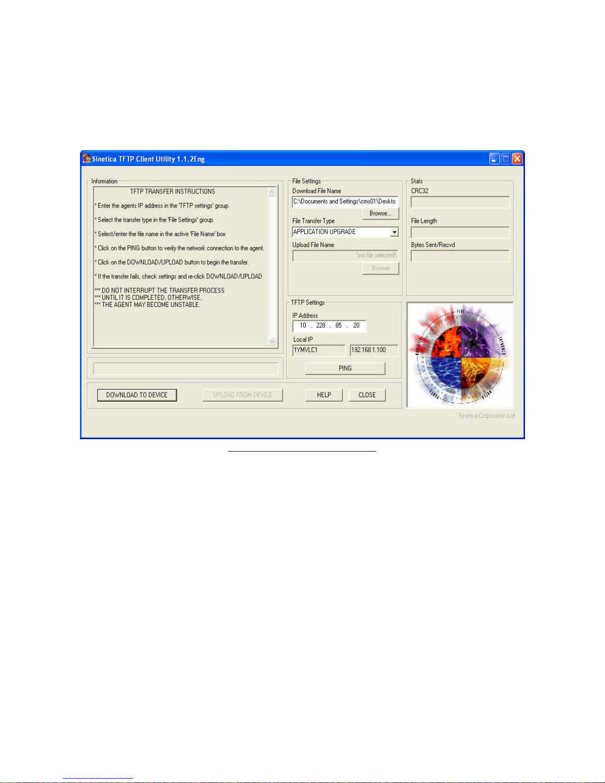
1. Open “SineticaTFTPclient.exe” on the Netcom CD.
2. In the 'File Settings' group select 'APPLICATION UPGRADE' from the 'File Transfer
Type' drop down list.
3. In the 'Download File Name' edit box select the name of the file, XX.XX.X.bin,
supplied on the Netcom 2 CD.
4. In the ‘TFTP Settings’ group enter the required IP address of the unit to be upgraded in
the ‘IP Address’ box.
5. Click the 'DOWNLOAD TO DEVICE' button. A blue task bar will flow from left to right
and data information will be displayed in the information box. When “connection closed”
appears the firmware installation will be complete.
6. The new configuration data will be written to the EEPROM in the Netcom2 unit
Rev 3 02/24/2009
3
Mitsubishi Netcom User Manual
7. If the Netcom is going to be communicating with a 2033A or 9700 the protocol will
have to be selected. This is done in the HyperTerminal session by typing ups m.
Figure 2 SineticaTFTPcliet.exe
The Netcom is ready to be connected to the UPS.
Rev 3 02/24/2009
4
Mitsubishi Netcom User Manual
6 How do I Install the Netcom?
The Netcom connects to the RS232 connector of the UPS. Please refer to the UPS
owner’s manual for the location.
** For the 9700 and 2033A UPS the special MIT RS232 connector kit must be used for
the connection between the UPS and the Netcom. This connection consists of the 25 pin
to 9 pin cable, a gender adapter and a network patch cable.
The DE9 to RJ45 cable is used to connect the Netcom to the UPS. The RJ45 connector is
inserted into the terminal identified as “UPS”. A network cable must be inserted into the
“Network” receptacle.
The Netcom requires a 120-volt AC power outlet that is UPS protected. If this is not
available an internal DC power supply can be purchased from Mitsubishi for the 9800,
2033G and 9900 series, all other UPS’s must use a external power supply. Please contact
your sales representative for full details.
7 Netcom Web Server
After completing the initial Netcom IP address assignment, software installation,
cable and Ethernet connections, and power connection, the Netcom will be ready to be
accessed.
7.1 Login Page
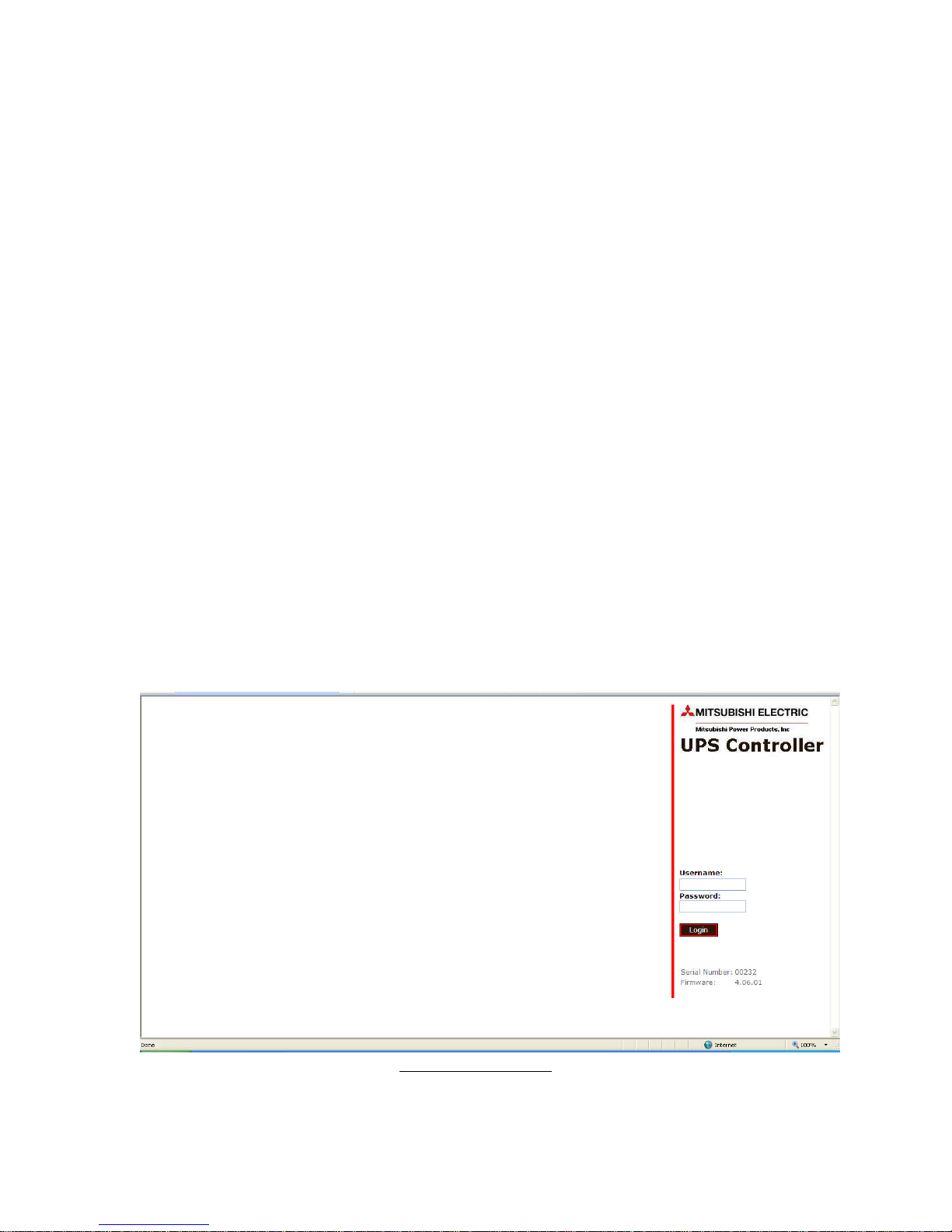
The default password for the Netcom is:
Rev 3 02/24/2009
Figure 3 Login Page
5

Mitsubishi Netcom User Manual
Username: admin
Password: admin
This Login Page shown in figure 3 is used for logging into the Netcom. The
default Username is admin, Password default is admin. This can be changed at the
Setup/users page along with several security options.
Rev 3 02/24/2009
6
Mitsubishi Netcom User Manual
7.2 UPS Status Page
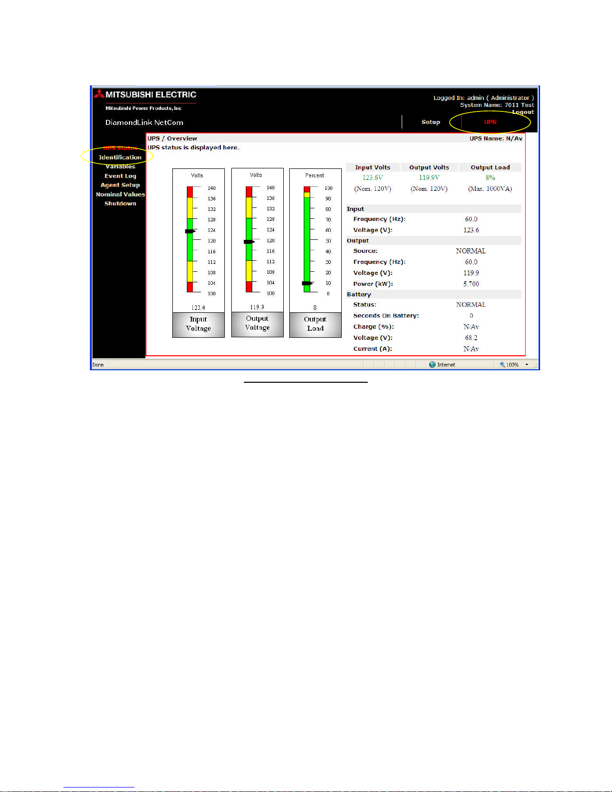
Click on UPS in top right corner and UPS Status to view UPS input voltage,
output voltage and output load.
Figure 4 UPS Status Page
Rev 3 02/24/2009
7
Mitsubishi Netcom User Manual
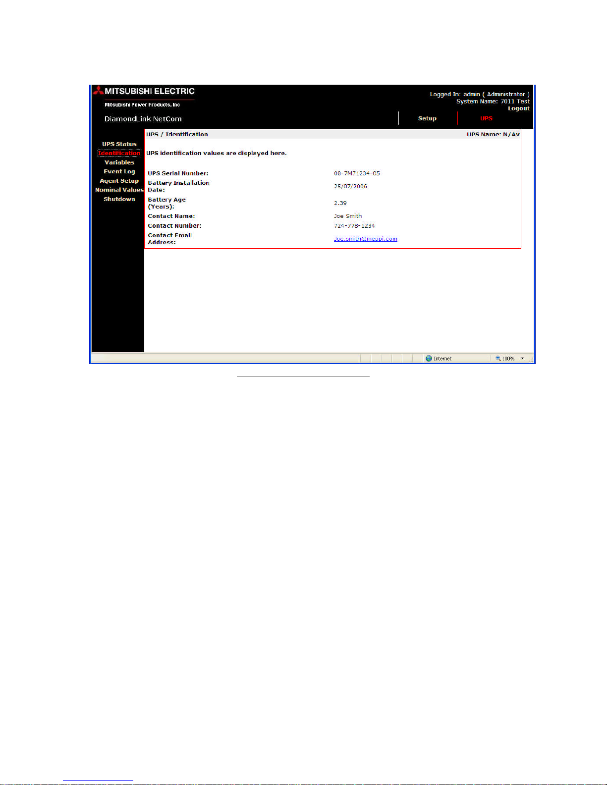
7.3 Identification Page
Figure 5 Identification Page
Click on the Identification menu option to display the UPS serial number, UPS
serial number, contact name, contact email, contact phone number and battery
information. This information is input at the Agent Setup menu (see figure 8).
Rev 3 02/24/2009
8
Mitsubishi Netcom User Manual
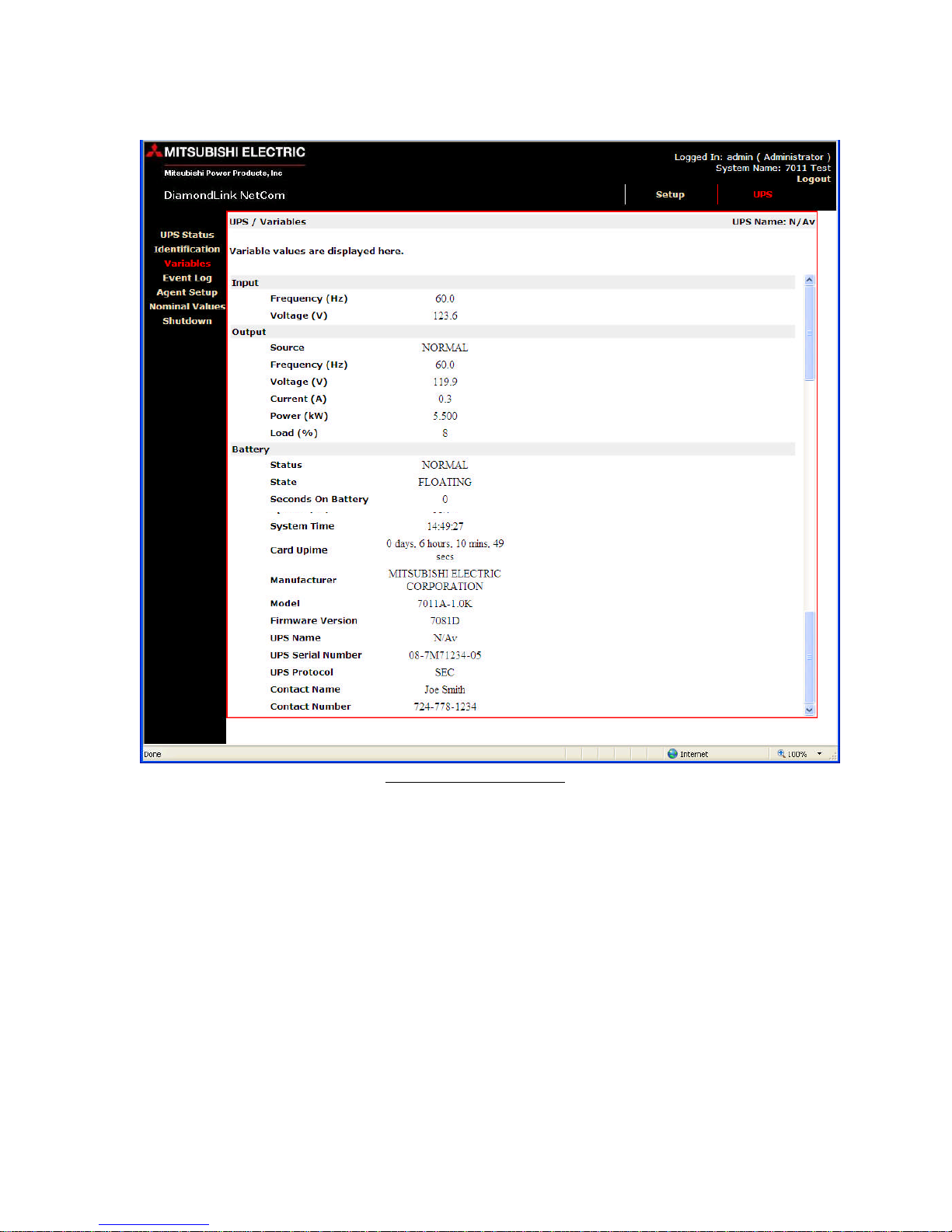
7.4 Variables Page
Click the Variables menu option to display the variables page. This page displays
a list of the available UPS variables. There are some variables that will not be displayed
depending on the unit that is being monitored. The list of variables will vary from unit to
unit.
Rev 3 02/24/2009
Figure 6 Variables Page
9
Mitsubishi Netcom User Manual
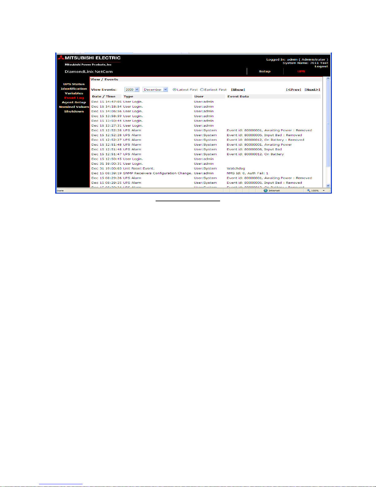
7.5 View Events Page
Figure 7 View/Events
Click on the Event Log menu option to display the View/Events page. The event
log will hold the latest events received from the UPS.
The events can be sorted by month, year and order of occurrence by selecting the View
Event.
When an event occurs, it will be written to the event log with a date/time stamp.
When the event is cleared (alarm removed), it will be written to the event log in the
format “event removed”, where event is the name of the event being cleared. Click the
Clear Log button to clear the event log.
Rev 3 02/24/2009
10
Mitsubishi Netcom User Manual
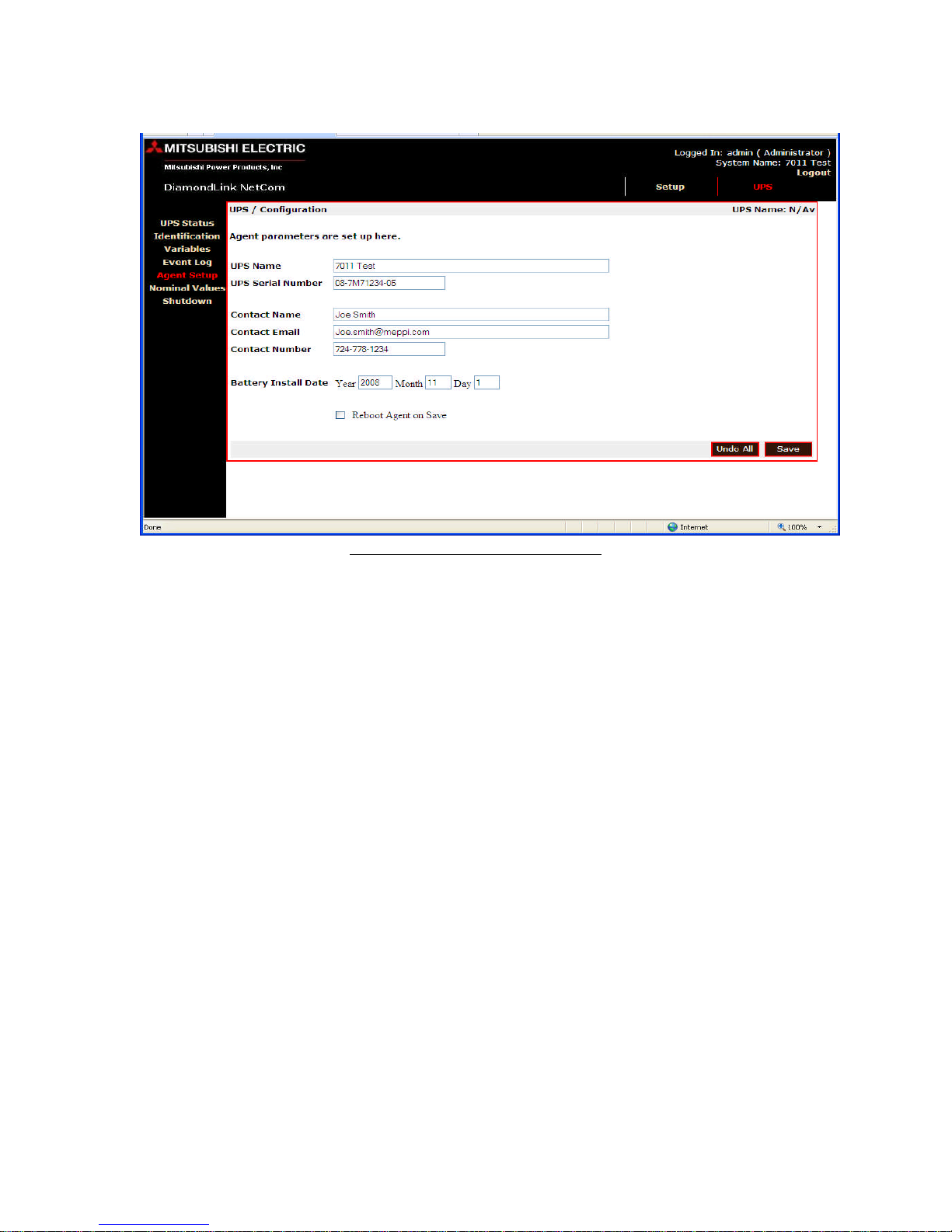
7.6 UPS/Configuration Page
Figure 8 UPS/Configuration Page
The Agent Setup (Netcom) page is where the UPS name, serial number, contact
name, contact email, and contact phone number can be inserted. The battery install date is
inserted into this field for battery age calculation that is available on the
UPS/Identification page.
Rev 3 02/24/2009
11
Mitsubishi Netcom User Manual
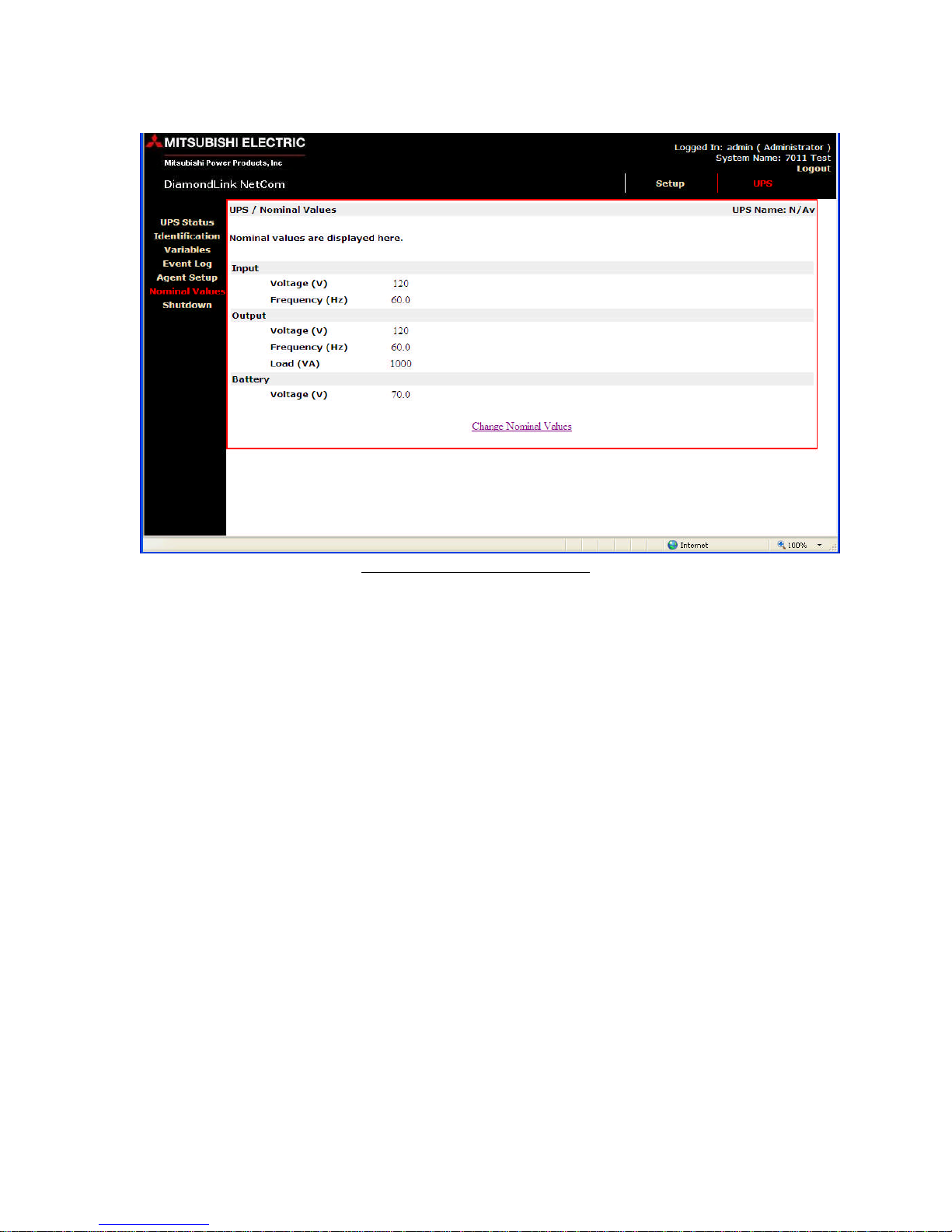
7.7 UPS Nominal Values Page
Figure 9 UPS Nominal Values
The UPS/Nominal Values page is were the UPS nominal values can be
changed. This information can be found in the UPS Owners/Technical for nominal
values.
Rev 3 02/24/2009
12
Mitsubishi Netcom User Manual
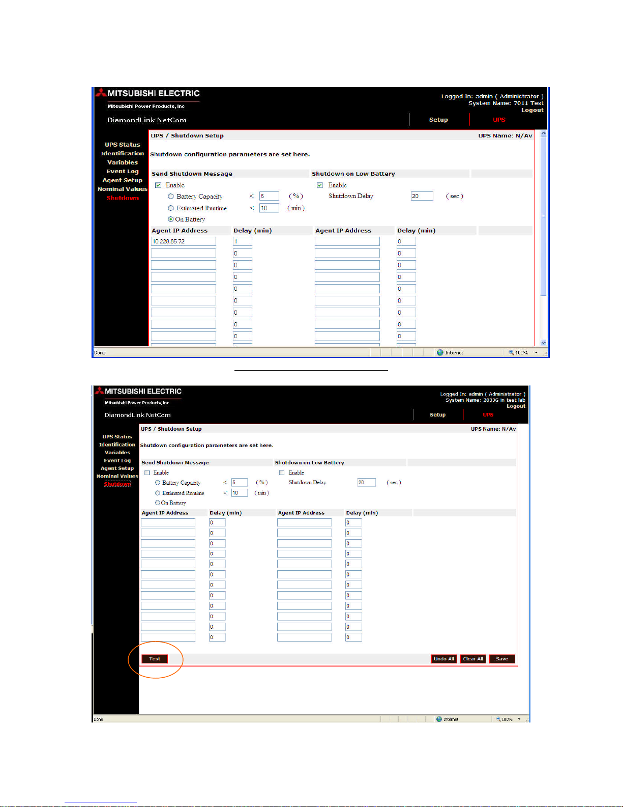
7.8 UPS Shutdown Setup Page
Figure 10 UPS Shutdown setup
Rev 3 02/24/2009
13

Mitsubishi Netcom User Manual
The UPS/Shutdown setup page can control 24 devices to be shut down when the
battery capacity reaches the customer’s preset limits. The Battery capacity percentage and
estimated runtime can be changed by selected the box and changing the default value if
available. The Agent IP Address is the IP address of the item that will be shut down
when the present values are reached. Click the Shutdown Setup menu option to modify
the shutdown configuration. Test button can be used to test the shut down function. This
button allows the user to test the shut down function of the IP address entered.You can
set the following values:
Send Shutdown Message You can configure the shutdown of remote computers
to be initiated on one of the following three conditions:
-Battery Capacity – Click the Battery Capacity radio button and enter a battery
capacity threshold (in percent). When the battery capacity falls below the
threshold value, a shutdown message will be sent to all listed systems if
available.
-Estimated Runtime – Click the Estimated Runtime radio button and enter a
runtime threshold (in minutes). When the estimated runtime falls below the
threshold value, a shutdown message will be sent to all listed systems.
Note: Not all UPS support the estimated runtime variable.
-On Battery – Click the On Battery radio button. When the UPS goes on
battery, a shutdown message will be sent to all listed systems.
Shutdown on Low Battery
Click the Enable check box to enable shutdown of remote systems based on a
UPS reported a low battery condition. Enter the delay (in seconds) from the time
the low battery message is sent to the remote system until the remote system
should initiate its shutdown.
Systems to Shut Down
You can send shutdown messages to up to 24 computers. For each system to be
shut down enter the following information:
-IP Address – Enter the IP Address for the computer to be shut down. Contact
your network administrator if you are unsure as to what value to use.
-Delay (min) – Enter the delay from the time the message is sent to the
computer until the system should initiate its shutdown. For example, a delay
of 2 will send the message to the remote shutdown agent that it should initiate
its shutdown in 2 minutes. If the utility power returns before the delay time as
elapsed, a message will be sent to the remote shutdown agent to cancel the
shutdown.
Rev 3 02/24/2009
14
Mitsubishi Netcom User Manual
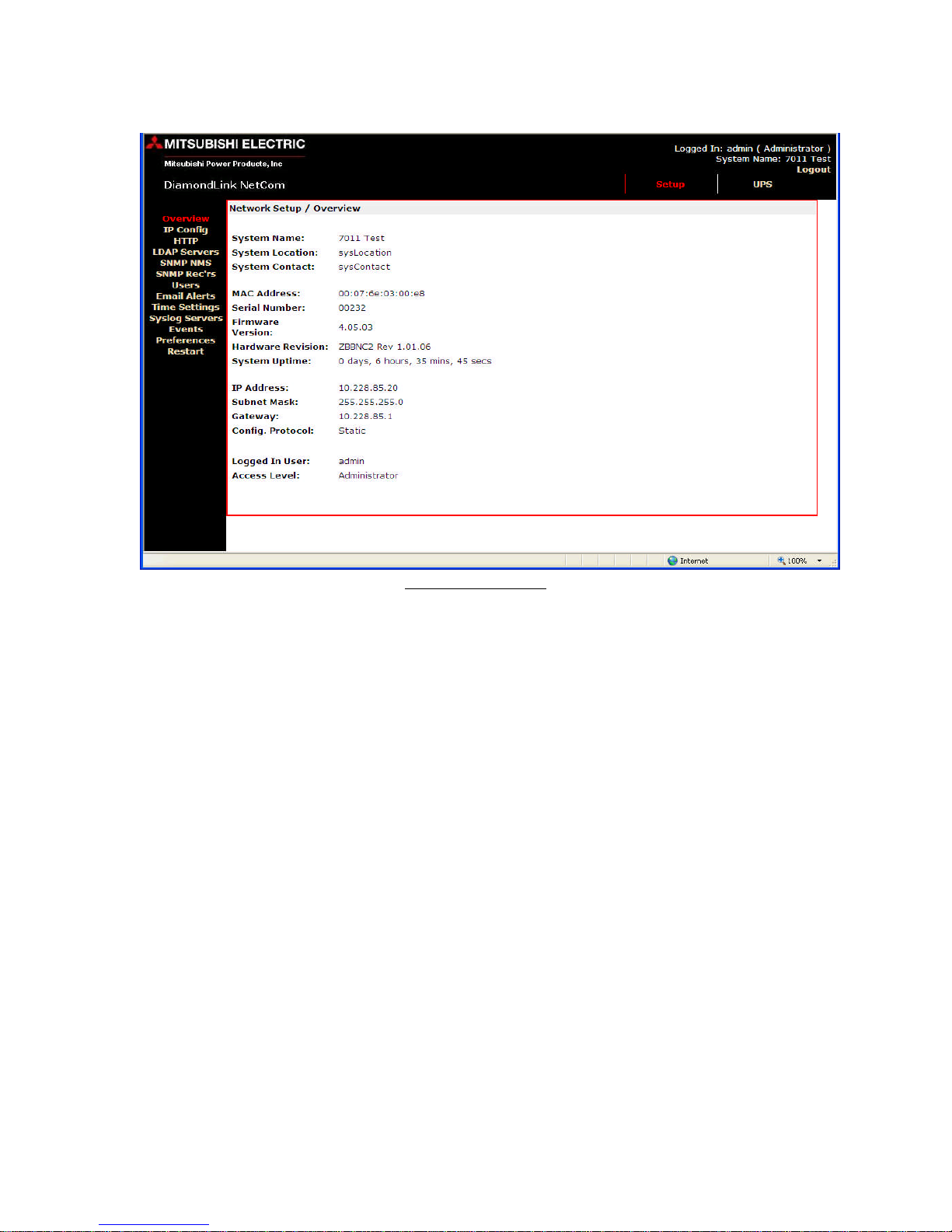
7.9 Network Setup Page
Figure 11 Network
The Network Setup/Overview page displays the systems name, MAC address,
serial number, firmware version, System uptime, IP information and user information.
Rev 3 02/24/2009
15

Mitsubishi Netcom User Manual
7.10 Setup/IP Configuration Page
Figure 12 Setup/IP configuration
At the Setup/ IP Configuration page the System name, IP address, Subnet Mask,
Gateway, and Config Protocol can be change. Check with your IT administrator for
recommended settings. The Config Protocol can be set to static, Dynamic Host
Configuration Protocol (DHCP) or Bootstrap Protocol (Bootp) by using the drop down
box.
Rev 3 02/24/2009
16

Mitsubishi Netcom User Manual
7.11 HTTP Setup Page
Figure 13 HTTP security
The HTTP protocol function can be set by selecting the radio button. The
unsecured port can be changed, but check with your IT administration and Network
firewalls for proper settings.
Rev 3 02/24/2009
17

Mitsubishi Netcom User Manual
7.12 Setup/LDAP Servers Page
Figure 14 Setup/LDAP Servers
Lightweight Directory Access Protocol (LDAP) has four options that are enabled
by the drop down box and two optional servers. The drop down box has Disable,
Primary, Secondary, and both. Your IT administration will be able to provide the
necessary information for this function to be used if needed.
Rev 3 02/24/2009
18

Mitsubishi Netcom User Manual
7.13 Setup SNMP Page
Figure 15 Setup SNMP NMS
The Setup/SNMP NMS function is used to set up the network management station
that will be viewing the UPS information using GETs and SETs. The Get operation is
used by the NMS to obtain the necessary information and the SETs command are used to
configure the management device for the information. The network management stations
that must access the units SNMP function must be entered at this page. For each Network
Management Station the following must be entered.
NMS IP Address- Enter the IP address for the NMS
Community – Enter the SNMP community string the NMS will use. Contact your
system administrator for details
NMS- The read only access permits the network management station to use only
GET commands. The Read/Write access permits the network management station
to use both GET and SET commands.
Note: A copy of the Netcom MIB files can be found on the Netcom CD, www.meppi.com,
or in Appendix B of this manual.
Rev 3 02/24/2009
19

Mitsubishi Netcom User Manual
7.14 SNMP Receivers Page
Figure 16 SNMP Receivers
The Setup/SNMP Rec’rs the IP address, community string and access permissions
are specified here for up to ten Network Management Stations. Any machine which will
be required to receive SNMP traps sent from this unit must be entered here.
Receive traps Enabled setting allows the specified NMS to receive the units standard
range of traps. Receive traps Enabled (incl Auth fails), will cause the unit to issue traps if
an unauthorized IP address attempts to access the units SNMP functions.
Rev 3 02/24/2009
20

Mitsubishi Netcom User Manual
7.15 Setup/Users Page
The Setup/Users page sets the permission for up to 20 users with three types of
permissions.
-Administration level allow access to change all setting.
-Controller level allows configuration settings to be viewed
-Viewer level allows configuration settings to be viewed
Figure 17 Setup/Users
Rev 3 02/24/2009
21

Mitsubishi Netcom User Manual
7.16 Setup/Email Alerts Page
Figure 18 Setup/Email Alerts
In the Setup/Email Alerts there are 10 email addresses that the UPS events can be
directed to. The Netcom can send email or alphanumeric pages when a UPS event occurs.
The Netcom uses your local email server to send the email/page. You must set the
following values (contact your network administer if you are unsure as to the values to
use).
-The SMTP relay server: enter the IP address of the local email server. The Netcom will
use this server to send the email/page
-The From Address: is the information that will appear in the subject line of the email
sent by the Netcom.
Rev 3 02/24/2009
22

Mitsubishi Netcom User Manual
7.17 Setup/Time Page
Figure 19 Setup/Time Setting
In the Setup/Time Setting page the date and time of the Netcom is set. This date is
used for the calculation of the battery life. The Simple Network Time Protocol (SNTP)
function can be used to synchronize the Netcom with your network, contact your network
administrator for more information of this function.
Rev 3 02/24/2009
23

Mitsubishi Netcom User Manual
7.18 Syslog Servers Page
Figure 20 Syslog Servers
The Setup/Syslog servers feature is not currently implemented; therefore we do
not support this function at this time. If this function is needed, please contact Mitsubishi
Technical Support.
Rev 3 02/24/2009
24

Mitsubishi Netcom User Manual
7.19 Preferences Page
Figure 21 Preferences
The Setup/Preferences page is used to set the default page of the Netcom. This
page allows the user to set the page that will be displayed after the initial log in session.
The default page and user session timeout options are set using the drop down box. The
temperature scale in a function not used by the UPS.
Rev 3 02/24/2009
25

Mitsubishi Netcom User Manual
7.20 Restart Page
Figure 22 Restart
The restart function will reset the unit’s runtime and will restart the Netcom. The
reset to factory defaults will reset many of the Netcom’s setting, if this option must be
performed record all values. The IP address will have to be reset when resetting to factory
defaults, but the Netcom will allow access one time after the reset to set the IP
information.
Rev 3 02/24/2009
26

Mitsubishi Netcom User Manual
8 Remote Shutdown Agents
8.1 Installing the Remote Shutdown Agent
The Remote Shutdown Agent should be installed on a computer that is being
powered by a UPS but is not communicating to it through the communications
cable. Installing this software will allow the Netcom to shut down remote
computers when events occur on the UPS.
8.1.1 Windows
Perform the following steps to install the remote shutdown agent on Windows:
1. Insert the CD.
2. Browse to the location on the CD for the Windows Agent.
3. Run the Setup file by double-clicking on it.
4. Reply to the standard installation prompts.
5. As an added security option, the Remote Shutdown Agent can be configured to
only shut down when it receives a shutdown message from a particular system.
From the remote shutdown agent configuration screen, enter the IP address of the
Netcom. Leave the field blank to allow any Netcom to connect to the remote
shutdown agent.
6. The shutdown agent can be configured to run in redundant mode. In redundant
mode, the computer will only be shut down when all configured systems have
sent a shutdown message. To set up the remote shutdown agent to be managed by
redundant systems click the radio button labeled This agent will be managed by
redundant servers.
7. Check the Netcom checkbox by the Netcom’s IP address.
8.1.2 Linux
Perform the following steps to install the remote shutdown agent on Linux:
1. Insert the CD.
2. Mount the CD.
3. Browse to the location of the Linux Management Server and run SetupRA.
4. During the installation you will be asked if redundant management servers will
manage the remote shutdown agent.
If you do not want to have a redundant setup answer ‘n’ at this prompt.
The installation will then ask for the IP address of the Netcom. Either
enter the specific IP address of the Netcom or enter a ‘*’ to allow any
Netcom to connect to it. Enter ‘y’ when asked if the managing server is a
Netcom.
If you do want to have a redundant setup then answer ‘y’ at this prompt.
The
Installation will then ask for the IP address of the first managing server. Either
enter the specific IP address of the Netcom or enter a ‘*’ to allow any Netcom
to connect to it. Enter ‘y’ when asked if the managing server is a Netcom.
Rev 3 02/24/2009
27

Mitsubishi Netcom User Manual
You will then be asked the same questions about the redundant Netcom.
8.1.3 HP-UX
Perform the following steps to install the remote shutdown agent on HP-UX:
1. Insert the CD.
2. Mount the CD.
3. Browse to the location of the HP-UX Management Server and run Install.
4. During the installation you will be asked if redundant management servers will
manage the remote shutdown agent.
If you do not want to have a redundant setup answer ‘n’ at this prompt.
The installation will then ask for the IP address of the Netcom. Either
enter the specific IP address of the Netcom or enter a ‘*’ to allow any
Netcom to connect to it. Enter ‘y’ when asked if the managing server is a
Netcom.
If you do want to have a redundant setup then answer ‘y’ at this prompt.
The installation will then ask for the IP address of the first Netcom. Either
enter the specific IP address of the Netcom or enter a ‘*’ to allow any
Netcom to connect to it. Enter ‘y’ when asked if the management server is
a Netcom. You will then be asked the same questions about the redundant
Netcom.
8.1.4 Solaris
Perform the following steps to install the remote shutdown agent on Solaris:
1. Insert the CD.
2. Mount the CD.
3. Browse to the location of the Linux Management Server and run install.
4. During the installation you will be asked if redundant management servers will
manage the remote shutdown agent.
If you do not want to have a redundant setup answer ‘n’ at this prompt.
The installation will then ask for the IP address of the Netcom. Either
enter the specific IP address of the Netcom or enter a ‘*’ to allow any
Netcom to connect to it. Enter ‘y’ when asked if the managing server is a
Netcom.
If you do want to have a redundant setup then answer ‘y’ at this prompt.
The installation will then ask for the IP address of the first Netcom. Either
enter the specific IP address of the Netcom or enter a ‘*’ to allow any
Netcom to connect to it. Enter ‘y’ when asked if the managing server is a
Netcom. You will then be asked the same questions about the redundant
Netcom.
8.1.5 AIX
Perform the following steps to install the remote shutdown agent on AIX:
1. Insert the CD.
2. Mount the CD.
3. Browse to the location of the Linux Management Server and run install.
Rev 3 02/24/2009
28

Mitsubishi Netcom User Manual
4. During the installation you will be asked if redundant management servers will
manage the remote shutdown agent.
If you do not want to have a redundant setup answer ‘n’ at this prompt.
The installation will then ask for the IP address of the Netcom. Either
enter the specific IP address of the Netcom or enter a ‘*’ to allow any
Netcom to connect to it. Enter ‘y’ when asked if the managing server is a
Netcom.
If you do want to have a redundant setup then answer ‘y’ at this prompt.
The installation will then ask for the IP address of the first Netcom. Either
enter the specific IP address of the Netcom or enter a ‘*’ to allow any
Netcom to connect to it. Enter ‘y’ when asked if the managing server is a
Netcom. You will then be asked the same questions about the redundant
Netcom.
8.1.6 Netware
Perform the following steps to install the remote shutdown agent on Netware:
1. Insert CD into the CD-ROM drive of the Netware Client computer.
2. From the Agent\Netware subdirectory of the CD, copy the contents into a
directory on the NetWare server.
3. From the NetWare system console, load the configuration module
(PMCONFIG.NLM) using the default path. For example, if the files were copied
into a folder called Mitsubishi on the SYS: volume, the module would be loaded
as follows: SYS:Mitsubishi/PMCONFIG
4. After accepting the License Agreement, you will be asked if redundant
Management Servers will manage your remote shutdown agent.
If you do not want to have a redundant setup then answer ‘n’ at this
prompt. The installation will then ask for the IP address of the Netcom.
Either enter the specific IP address of the Netcom or enter a ‘*’ to allow
any Netcom to connect to it. Enter ‘y’ when asked if the managing server
is a Netcom.
If you do want to have a redundant setup then answer ‘y’ at this prompt.
The installation will then ask for the IP address of the first Netcom. Either
enter the specific IP address or enter a ‘*’ to allow any Netcom to connect
to it. Enter ‘y’ when asked if the managing server is a Netcom or ‘n’ if not.
You will then be asked the same questions about the second management
server.
8.1.7 Mac OS X
Perform the following steps to install the remote shutdown agent on Mac OS X:
1. Copy the DiamondLinkRAX.X-OSX.tar.gz file to your hard drive. Browse to
its location with the Mac file manager.
2. Click the icon for the DiamondLinkRAX.X-OSX.tar.gz file.
3. A new folder named DiamondLinkRAX.X-OSX will be created in the same
location as the DiamondLinkRAX.X-OSX.tar.gz file.
4. Browse into the new folder.
5. Click on the DiamondLinkRAX.X-OSX.pkg file.
Rev 3 02/24/2009
29

Mitsubishi Netcom User Manual
6. Follow the installation prompts to install the software.
7. Following the completion of the installation, the files will be installed but the
service will need to be started.
Perform the following steps to configure and start the remote shutdown agent:
Starting and Configuring the Remote Agent Service:
1. Open a command terminal.
2. While logged in as root, run the following command: /etc/DevMan setup
3. The script will now ask you questions about configuring the software.
4. The setup will ask you to specify the IP address of the Netcom. Leave this
address blank if you want to allow any Netcom to manage the shutdown agent.
5. The DevMan script has other useful options. Rut it without the setup argument
to see the Usage line.
Perform the following steps to uninstall the remote shutdown agent:
1. Open a command terminal.
2. Go to the location where you unzipped the DiamondLinkRAX.X-OSX.tar.gz
file during the installation.
3. Go into the DiamondLinkRAX.X-OSX folder that was created.
4. Run the following command: ./Uninstall
8.2 Configuring the Remote Shutdown Agents from the Netcom
Select the Shutdown Setup menu option from the Netcom user interface to
configure the Netcom to shut down remote computers.
9 Netcom Forwarder
The Netcom is limited to shutting down 24 remote computers. If there is a need to
shut down additional computers, you can use the Netcom Forwarder to do so. The
Netcom Forwarder is purchased as a separate software product. Contact Mitsubishi or
your Netcom vendor to purchase this software. The Netcom Forwarder will run on
Windows XP Professional, Windows 2000 or Windows 2003.
9.1 Installing and Configuring the Forwarder Agent
Perform the following steps to install the Forwarder Agent:
1. Insert the CD. The installation will start automatically. Reply to the standard
prompts.
2. Configure the forwarder to communicate with the Netcom. Enter the IP address
of the Netcom and check the Netcom box.
9.2 Configuring the Netcom to send shutdown messages to the Forwarder Agent
Perform the following steps to configure the Netcom to send alarms to the
Forwarder Agent:
1. Browse to the Netcom and select the Shutdown Setup menu option.
Rev 3 02/24/2009
30

Mitsubishi Netcom User Manual
2. Enter the IP address of the computer running the forwarder into one of the
available Agent IP Address edit fields. Set the delay to 0.
9.3 Configuring the Forwarder Agent to Shut Down Remote Computers
Perform the following steps to add remote shutdown agents to the Forwarder Agent:
1. On the computer running the forwarder agent, select Start > Mitsubishi
DiamondLink > Configure Forwarder. The following screen will be displayed:
2. Click the Add Agent button.
3. Enter the IP Address of the computer to be shut down.
Note: This computer must be running the Remote Shutdown Agent
software.
4. Enter the time (in seconds) the remote system should wait after it receives the
shutdown message until it initiates a system shutdown.
5. Click the OK button.
Repeat this process for each remote computer to be shut down.
To edit an existing agent, select the agent from the list and click the Edit button.
Modify the agent and click the OK button to save the changes.
To delete an existing agent, select the agent from the list and click the Delete
Agent button. Important! The forwarder service must be restarted in order for any
changes (add, edit or delete) to take effect. To restart the service you can either
reboot your computer or stop and restart the DiamondLink Remote Shutdown
Agent Forwarder service using
Start > Control Panel > Administrative Tools > Services.
9.4 Configuring the Remote Shutdown Agents to Receive Messages from the Forwarder
Agent
Each shutdown agent must be configured to receive messages from the Forwarder Agent.
On the remote agent configuration screen, enter the IP address of the Forwarder Agent.
Make sure that you check the Netcom check box.
Rev 3 02/24/2009
31

Mitsubishi Netcom User Manual
APPENDIX A
Appendix A: RJ45 to DE9 connection
RS232 Wiring Connections: Netcom-2 to PC Com Port.
Netcom-2 PC
RJ45 D sub
Ground
RS232 RxD
(i/p)
Do Not Connect
Do Not Connect
Do Not Connect
Do Not Connect
RS232 TxD
(o/p)
Ground
1 < --------------------------
>
2 < --------------------------
-3
4
5
6
7 ----------------------------
>
8 < --------------------------
>
5
TxD (o/p) RS232
3
RxD (i/p) RS232
2
5
Rev 3 02/24/2009
32

Appendix B: MIB file
-- Mitsubishi.mib - MIB file for Mitsubishi UPSs
UPS-MIB DEFINITIONS ::= BEGIN
IMPORTS
PositiveInteger ::= INTEGER
NonNegativeInteger ::= INTEGER
TimeStamp ::= TimeTicks
TimeInterval ::= INTEGER (0..2147483647)
TestAndIncr ::= INTEGER (0..2147483647)
AutonomousType ::= DisplayString
Mitsubishi Netcom User Manual
APPENDIX B
TRAP-TYPE
FROM RFC-1215
DisplayString
FROM RFC1213-MIB
OBJECT-TYPE
FROM RFC-1212
Gauge, Counter, TimeTicks, mgmt
FROM RFC1155-SMI
;
Tag OBJECT IDENTIFIER ::= { enterprises 13891 }
MitsubishiUPS OBJECT IDENTIFIER ::= { Tag 101 }
upsIdent OBJECT IDENTIFIER ::= { MitsubishiUPS 1 }
upsIdentManufacturer OBJECT-TYPE
SYNTAX DisplayString
ACCESS read-only
STATUS mandatory
DESCRIPTION
"The name of the UPS manufacturer."
::= { upsIdent 1 }
upsIdentModel OBJECT-TYPE
SYNTAX DisplayString
ACCESS read-only
STATUS mandatory
DESCRIPTION
"The UPS Model designation."
::= { upsIdent 2 }
upsIdentUPSSoftwareVersion OBJECT-TYPE
SYNTAX DisplayString
ACCESS read-only
STATUS mandatory
DESCRIPTION
"The UPS firmware/software version(s). This variable
may or may not have the same value as
upsIdentAgentSoftwareVersion in some implementations."
::= { upsIdent 3 }
Rev 3 02/24/2009
33

Mitsubishi Netcom User Manual
upsIdentAgentSoftwareVersion OBJECT-TYPE
SYNTAX DisplayString
ACCESS read-only
STATUS mandatory
DESCRIPTION
"The UPS agent software version. This variable may or may
not have the same value as upsIdentUPSSoftwareVersion in
some implementations."
::= { upsIdent 4 }
upsIdentName OBJECT-TYPE
SYNTAX DisplayString
ACCESS read-write
STATUS mandatory
DESCRIPTION
"A string identifying the UPS. This object should be
set by the administrator."
::= { upsIdent 5 }
upsIdentAttachedDevices OBJECT-TYPE
SYNTAX DisplayString
ACCESS read-write
STATUS mandatory
DESCRIPTION
"A string identifying the devices attached to the output
of the UPS. This object should be set by the
administrator."
::= { upsIdent 6 }
upsBattery OBJECT IDENTIFIER ::= { MitsubishiUPS 2 }
upsBatteryStatus OBJECT-TYPE
SYNTAX INTEGER
{
unknown(1),
batteryNormal(2),
batteryLow(3),
batteryDepleted(4)
}
ACCESS read-only
STATUS mandatory
DESCRIPTION
"The indication of the capacity remaining in the UPS
batteries.
A value of batteryNormal indicates a normal battery
condition.
A value of batteryLow indicates the remaining battery run-
time
will not maintain the output load for an extended period of
time.
A value of batteryDepleted indicates that the UPS will be
unable
to sustain the present load when and if the utility power
is lost."
::= { upsBattery 1 }
Rev 3 02/24/2009
34

Mitsubishi Netcom User Manual
upsSecondsOnBattery OBJECT-TYPE
SYNTAX NonNegativeInteger -- UNITS seconds
ACCESS read-only
STATUS mandatory
DESCRIPTION
"If the unit is on battery power, the elapsed time in
seconds
since the UPS last switched to battery power, or the time
since
the network management system was last restarted, whichever
is less.
Zero shall be returned if the unit is not on battery
power."
::= { upsBattery 2 }
upsEstimatedMinutesRemaining OBJECT-TYPE
SYNTAX PositiveInteger -- UNITS minutes
ACCESS read-only
STATUS mandatory
DESCRIPTION
"An estimate of the time in minutes until the battery is
depleted
under the present load conditions if the utility power is
off and
remains off, or if it were to be lost and remain off."
::= { upsBattery 3 }
upsEstimatedChargeRemaining OBJECT-TYPE
SYNTAX INTEGER -- UNITS percent
ACCESS read-only
STATUS mandatory
DESCRIPTION
"An estimate of the battery charge remaining expressed as a
percent of full charge."
::= { upsBattery 4 }
upsBatteryVoltage OBJECT-TYPE
SYNTAX NonNegativeInteger -- UNITS 0.1 Volt DC
ACCESS read-only
STATUS mandatory
DESCRIPTION
"The magnitude of the present battery voltage (0.1 Volt
DC)."
::= { upsBattery 5 }
upsBatteryCurrent OBJECT-TYPE
SYNTAX INTEGER (-2147483648..2147483647) -- UNITS 0.1 Amp DC
ACCESS read-only
STATUS mandatory
DESCRIPTION
"The present battery current (0.1 Amp DC)."
::= { upsBattery 6 }
upsBatteryTemperature OBJECT-TYPE
SYNTAX INTEGER (-2147483648..2147483647) -- UNITS degrees
Centigrade
ACCESS read-only
Rev 3 02/24/2009
35

Mitsubishi Netcom User Manual
STATUS mandatory
DESCRIPTION
"The ambient temperature at or near the UPS Battery casing
(degrees Centigrade)."
::= { upsBattery 7 }
upsInput OBJECT IDENTIFIER ::= { MitsubishiUPS 3 }
upsInputLineBads OBJECT-TYPE
SYNTAX Counter
ACCESS read-only
STATUS mandatory
DESCRIPTION
"A count of the number of times the input entered an
out-of-tolerance condition as defined by the manufacturer.
This count is incremented by one each time the input
transitions from zero out-of-tolerance lines to one or more
input lines out-of-tolerance."
::= { upsInput 1 }
upsInputNumLines OBJECT-TYPE
SYNTAX NonNegativeInteger
ACCESS read-only
STATUS mandatory
DESCRIPTION
"The number of input lines utilized in this device. This
variable indicates the number of rows in the input table."
::= { upsInput 2 }
upsInputTable OBJECT-TYPE
SYNTAX SEQUENCE OF UpsInputEntry
ACCESS not-accessible
STATUS mandatory
DESCRIPTION
"A list of input table entries. The number of entries
is given by the value of upsInputNumLines."
::= { upsInput 3 }
upsInputEntry OBJECT-TYPE
SYNTAX UpsInputEntry
ACCESS not-accessible
STATUS mandatory
DESCRIPTION
"An entry containing information applicable to a
particular input line."
INDEX { upsInputLineIndex }
::= { upsInputTable 1 }
UpsInputEntry ::=
SEQUENCE
{
upsInputLineIndex PositiveInteger,
upsInputFrequency NonNegativeInteger,
upsInputVoltage NonNegativeInteger,
upsInputCurrent NonNegativeInteger,
upsInputTruePower NonNegativeInteger
}
Rev 3 02/24/2009
36

Mitsubishi Netcom User Manual
upsInputLineIndex OBJECT-TYPE
SYNTAX PositiveInteger
ACCESS read-only
STATUS mandatory
DESCRIPTION
"The input line identifier."
::= { upsInputEntry 1 }
upsInputFrequency OBJECT-TYPE
SYNTAX NonNegativeInteger -- UNITS 0.1 Hertz
ACCESS read-only
STATUS mandatory
DESCRIPTION
"The present input frequency (0.1 Hertz)."
::= { upsInputEntry 2 }
upsInputVoltage OBJECT-TYPE
SYNTAX NonNegativeInteger -- UNITS 0.1 RMS Volt
ACCESS read-only
STATUS mandatory
DESCRIPTION
"The magnitude of the present input voltage (0.1 RMS Volt)."
::= { upsInputEntry 3 }
upsInputCurrent OBJECT-TYPE
SYNTAX NonNegativeInteger -- UNITS 0.1 RMS Amp
ACCESS read-only
STATUS mandatory
DESCRIPTION
"The magnitude of the present input current (0.1 RMS Amp)."
::= { upsInputEntry 4 }
upsInputTruePower OBJECT-TYPE
SYNTAX NonNegativeInteger -- UNITS Watts
ACCESS read-only
STATUS mandatory
DESCRIPTION
"The magnitude of the present input true power (watts)."
::= { upsInputEntry 5 }
upsOutput OBJECT IDENTIFIER ::= { MitsubishiUPS 4 }
upsOutputSource OBJECT-TYPE
SYNTAX INTEGER
{
other(1),
none(2),
normal(3),
bypass(4),
battery(5),
booster(6),
reducer(7)
}
ACCESS read-only
STATUS mandatory
DESCRIPTION
Rev 3 02/24/2009
37

Mitsubishi Netcom User Manual
"The present source of output power. A value of none (2)
indicates
there is no source of output power (and therefore no output
power),
for example, the system has opened the output breaker."
::= { upsOutput 1 }
upsOutputFrequency OBJECT-TYPE
SYNTAX NonNegativeInteger -- UNITS 0.1 Hertz
ACCESS read-only
STATUS mandatory
DESCRIPTION
"The present output frequency (0.1 Hertz)."
::= { upsOutput 2 }
upsOutputNumLines OBJECT-TYPE
SYNTAX NonNegativeInteger
ACCESS read-only
STATUS mandatory
DESCRIPTION
"The number of output lines utilized in this device. This
variable indicates the number of rows in the output table."
::= { upsOutput 3 }
upsOutputTable OBJECT-TYPE
SYNTAX SEQUENCE OF UpsOutputEntry
ACCESS not-accessible
STATUS mandatory
DESCRIPTION
"A list of output table entries. The number of
entries is given by the value of upsOutputNumLines."
::= { upsOutput 4 }
upsOutputEntry OBJECT-TYPE
SYNTAX UpsOutputEntry
ACCESS not-accessible
STATUS mandatory
DESCRIPTION
"An entry containing information applicable to a
particular output line."
INDEX { upsOutputLineIndex }
::= { upsOutputTable 1 }
UpsOutputEntry ::=
SEQUENCE
{
upsOutputLineIndex PositiveInteger,
upsOutputVoltage NonNegativeInteger,
upsOutputCurrent NonNegativeInteger,
upsOutputPower NonNegativeInteger,
upsOutputPercentLoad INTEGER
}
upsOutputLineIndex OBJECT-TYPE
SYNTAX PositiveInteger
ACCESS read-only
STATUS mandatory
Rev 3 02/24/2009
38

Mitsubishi Netcom User Manual
DESCRIPTION
"The output line identifier."
::= { upsOutputEntry 1 }
upsOutputVoltage OBJECT-TYPE
SYNTAX NonNegativeInteger -- UNITS 0.1 RMS Volts
ACCESS read-only
STATUS mandatory
DESCRIPTION
"The present output voltage (0.1 RMS Volt)."
::= { upsOutputEntry 2 }
upsOutputCurrent OBJECT-TYPE
SYNTAX NonNegativeInteger -- UNITS 0.1 RMS Amp
ACCESS read-only
STATUS mandatory
DESCRIPTION
"The present output current (0.1 RMS Amp)."
::= { upsOutputEntry 3 }
upsOutputPower OBJECT-TYPE
SYNTAX NonNegativeInteger -- UNITS Watts
ACCESS read-only
STATUS mandatory
DESCRIPTION
"The present output true power (watts)."
::= { upsOutputEntry 4 }
upsOutputPercentLoad OBJECT-TYPE
SYNTAX INTEGER -- UNITS percent
ACCESS read-only
STATUS mandatory
DESCRIPTION
"The percentage of the UPS power capacity presently being
used on this output line (the greater of the percent load
of true power capacity and the percent load of VA."
::= { upsOutputEntry 5 }
upsBypass OBJECT IDENTIFIER ::= { MitsubishiUPS 5 }
upsBypassFrequency OBJECT-TYPE
SYNTAX NonNegativeInteger -- UNITS 0.1 Hertz
ACCESS read-only
STATUS mandatory
DESCRIPTION
"The present bypass frequency."
::= { upsBypass 1 }
upsBypassNumLines OBJECT-TYPE
SYNTAX NonNegativeInteger
ACCESS read-only
STATUS mandatory
DESCRIPTION
"The number of bypass lines utilized in this device. This
entry indicates the number of rows in the bypass table."
::= { upsBypass 2 }
Rev 3 02/24/2009
39

Mitsubishi Netcom User Manual
upsBypassTable OBJECT-TYPE
SYNTAX SEQUENCE OF UpsBypassEntry
ACCESS not-accessible
STATUS mandatory
DESCRIPTION
"A list of bypass table entries. The number of entries
is given by the value of upsBypassNumLines."
::= { upsBypass 3 }
upsBypassEntry OBJECT-TYPE
SYNTAX UpsBypassEntry
ACCESS not-accessible
STATUS mandatory
DESCRIPTION
"An entry containing information applicable to a
particular bypass input."
INDEX { upsBypassLineIndex }
::= { upsBypassTable 1 }
UpsBypassEntry ::=
SEQUENCE
{
upsBypassLineIndex PositiveInteger,
upsBypassVoltage NonNegativeInteger,
upsBypassCurrent NonNegativeInteger,
upsBypassPower NonNegativeInteger
}
upsBypassLineIndex OBJECT-TYPE
SYNTAX PositiveInteger
ACCESS read-only
STATUS mandatory
DESCRIPTION
"The bypass line identifier."
::= { upsBypassEntry 1 }
upsBypassVoltage OBJECT-TYPE
SYNTAX NonNegativeInteger -- UNITS 0.1 RMS Volts
ACCESS read-only
STATUS mandatory
DESCRIPTION
"The present bypass voltage (0.1 RMS Volt)."
::= { upsBypassEntry 2 }
upsBypassCurrent OBJECT-TYPE
SYNTAX NonNegativeInteger -- UNITS 0.1 RMS Amp
ACCESS read-only
STATUS mandatory
DESCRIPTION
"The present bypass current (0.1 RMS Amp)."
::= { upsBypassEntry 3 }
upsBypassPower OBJECT-TYPE
SYNTAX NonNegativeInteger -- UNITS Watts
ACCESS read-only
STATUS mandatory
DESCRIPTION
Rev 3 02/24/2009
40

Mitsubishi Netcom User Manual
"The present true power conveyed by the bypass (watts)."
::= { upsBypassEntry 4 }
upsAlarm OBJECT IDENTIFIER ::= { MitsubishiUPS 6 }
upsAlarmsPresent OBJECT-TYPE
SYNTAX Gauge
ACCESS read-only
STATUS mandatory
DESCRIPTION
"The present number of active alarm conditions."
::= { upsAlarm 1 }
upsAlarmTable OBJECT-TYPE
SYNTAX SEQUENCE OF UpsAlarmEntry
ACCESS not-accessible
STATUS mandatory
DESCRIPTION
"A list of alarm table entries. Alarms are named by
an OBJECT IDENTIFIER, upsAlarmDescr, to allow a single
table to reflect well known alarms plus alarms defined
by a particular implementation, i.e., as documented in
the private enterprise MIB definition for the device.
No two rows will have the same value of upsAlarmDescr,
since alarms define conditions. In order to meet this
requirement, care should be taken in the definition of
alarm conditions to insure that a system cannot enter
the same condition multiple times simultaneously.
The number of rows in the table at any given time is
reflected by the value of upsAlarmsPresent."
::= { upsAlarm 2 }
upsAlarmEntry OBJECT-TYPE
SYNTAX UpsAlarmEntry
ACCESS not-accessible
STATUS mandatory
DESCRIPTION
"An entry containing information applicable to a
particular alarm."
INDEX { upsAlarmId }
::= { upsAlarmTable 1 }
UpsAlarmEntry ::=
SEQUENCE
{
upsAlarmId PositiveInteger,
upsAlarmDescr AutonomousType,
upsAlarmTime TimeStamp
}
upsAlarmId OBJECT-TYPE
SYNTAX PositiveInteger
ACCESS read-only
STATUS mandatory
DESCRIPTION
"A unique identifier for an alarm condition. This
Rev 3 02/24/2009
41

Mitsubishi Netcom User Manual
value must remain constant."
::= { upsAlarmEntry 1 }
upsAlarmDescr OBJECT-TYPE
SYNTAX AutonomousType
ACCESS read-only
STATUS mandatory
DESCRIPTION
"A reference to an alarm description object. The object
referenced should not be accessible, but rather be used
to provide a unique description of the alarm condition."
::= { upsAlarmEntry 2 }
upsAlarmTime OBJECT-TYPE
SYNTAX TimeStamp
ACCESS read-only
STATUS mandatory
DESCRIPTION
"The value of sysUpTime when the alarm condition was
detected. If the alarm condition was detected at the
time of agent startup and presumably existed before
agent startup, the value of upsAlarmTime shall equal 0."
::= { upsAlarmEntry 3 }
upsAlarmID OBJECT-TYPE
SYNTAX INTEGER
ACCESS read-only
STATUS mandatory
DESCRIPTION
"A unique identifier for an alarm condition. This
value must remain constant."
::= { upsAlarm 4 }
upsAlarmDESCR OBJECT-TYPE
SYNTAX DisplayString (SIZE(0..63))
ACCESS read-only
STATUS mandatory
DESCRIPTION
"A reference to an alarm description object. The object
references should not be accessible, but rather be used
to provide a unique description of the alarm condition."
::= { upsAlarm 5 }
upsWellKnownAlarms OBJECT IDENTIFIER ::= { upsAlarm 3 }
upsAlarmBatteryBad OBJECT-TYPE
SYNTAX INTEGER
ACCESS read-only
STATUS mandatory
DESCRIPTION
"One or more batteries have been determined to require
replacement."
::= { upsWellKnownAlarms 1 }
upsAlarmOnBattery OBJECT-TYPE
SYNTAX INTEGER
ACCESS read-only
Rev 3 02/24/2009
42

Mitsubishi Netcom User Manual
STATUS mandatory
DESCRIPTION
"The UPS is drawing power from the batteries."
::= { upsWellKnownAlarms 2 }
upsAlarmLowBattery OBJECT-TYPE
SYNTAX INTEGER
ACCESS read-only
STATUS mandatory
DESCRIPTION
"The remaining battery run-time is less than or equal
to upsConfigLowBattTime."
::= { upsWellKnownAlarms 3 }
upsAlarmDepletedBattery OBJECT-TYPE
SYNTAX INTEGER
ACCESS read-only
STATUS mandatory
DESCRIPTION
"The UPS will be unable to sustain the present load
when and if the utility power is lost."
::= { upsWellKnownAlarms 4 }
upsAlarmTempBad OBJECT-TYPE
SYNTAX INTEGER
ACCESS read-only
STATUS mandatory
DESCRIPTION
"A temperature is out of tolerance."
::= { upsWellKnownAlarms 5 }
upsAlarmInputBad OBJECT-TYPE
SYNTAX INTEGER
ACCESS read-only
STATUS mandatory
DESCRIPTION
"An input condition is out of tolerance."
::= { upsWellKnownAlarms 6 }
upsAlarmOutputBad OBJECT-TYPE
SYNTAX INTEGER
ACCESS read-only
STATUS mandatory
DESCRIPTION
"An output condition (other than OutputOverload) is
out of tolerance."
::= { upsWellKnownAlarms 7 }
upsAlarmOutputOverload OBJECT-TYPE
SYNTAX INTEGER
ACCESS read-only
STATUS mandatory
DESCRIPTION
"The output load exceeds the UPS output capacity."
::= { upsWellKnownAlarms 8 }
upsAlarmOnBypass OBJECT-TYPE
Rev 3 02/24/2009
43

Mitsubishi Netcom User Manual
SYNTAX INTEGER
ACCESS read-only
STATUS mandatory
DESCRIPTION
"The Bypass is presently engaged on the UPS."
::= { upsWellKnownAlarms 9 }
upsAlarmBypassBad OBJECT-TYPE
SYNTAX INTEGER
ACCESS read-only
STATUS mandatory
DESCRIPTION
"The Bypass is out of tolerance."
::= { upsWellKnownAlarms 10 }
upsAlarmOutputOffAsRequested OBJECT-TYPE
SYNTAX INTEGER
ACCESS read-only
STATUS mandatory
DESCRIPTION
"The UPS has shut down as requested, i.e., the output
is off."
::= { upsWellKnownAlarms 11 }
upsAlarmUpsOffAsRequested OBJECT-TYPE
SYNTAX INTEGER
ACCESS read-only
STATUS mandatory
DESCRIPTION
"The entire UPS has shutdown as commanded."
::= { upsWellKnownAlarms 12 }
upsAlarmChargerFailed OBJECT-TYPE
SYNTAX INTEGER
ACCESS read-only
STATUS mandatory
DESCRIPTION
"An uncorrected problem has been detected within the
UPS charger subsystem."
::= { upsWellKnownAlarms 13 }
upsAlarmUpsOutputOff OBJECT-TYPE
SYNTAX INTEGER
ACCESS read-only
STATUS mandatory
DESCRIPTION
"The output of the UPS is in the off state."
::= { upsWellKnownAlarms 14 }
upsAlarmUpsSystemOff OBJECT-TYPE
SYNTAX INTEGER
ACCESS read-only
STATUS mandatory
DESCRIPTION
"The UPS system is in the off state."
::= { upsWellKnownAlarms 15 }
Rev 3 02/24/2009
44

Mitsubishi Netcom User Manual
upsAlarmFanFailure OBJECT-TYPE
SYNTAX INTEGER
ACCESS read-only
STATUS mandatory
DESCRIPTION
"The failure of one or more fans in the UPS has been
detected."
::= { upsWellKnownAlarms 16 }
upsAlarmFuseFailure OBJECT-TYPE
SYNTAX INTEGER
ACCESS read-only
STATUS mandatory
DESCRIPTION
"The failure of one or more fuses has been detected."
::= { upsWellKnownAlarms 17 }
upsAlarmGeneralFault OBJECT-TYPE
SYNTAX INTEGER
ACCESS read-only
STATUS mandatory
DESCRIPTION
"A general fault in the UPS has been detected."
::= { upsWellKnownAlarms 18 }
upsAlarmDiagnosticTestFailed OBJECT-TYPE
SYNTAX INTEGER
ACCESS read-only
STATUS mandatory
DESCRIPTION
"The result of the last diagnostic test indicates a
failure."
::= { upsWellKnownAlarms 19 }
upsAlarmCommunicationsLost OBJECT-TYPE
SYNTAX INTEGER
ACCESS read-only
STATUS mandatory
DESCRIPTION
"A problem has been encountered in the
communications between the agent and the UPS."
::= { upsWellKnownAlarms 20 }
upsAlarmAwaitingPower OBJECT-TYPE
SYNTAX INTEGER
ACCESS read-only
STATUS mandatory
DESCRIPTION
"The UPS output is off and the UPS is awaiting the
return of input power."
::= { upsWellKnownAlarms 21 }
upsAlarmShutdownPending OBJECT-TYPE
SYNTAX INTEGER
ACCESS read-only
STATUS mandatory
DESCRIPTION
Rev 3 02/24/2009
45

Mitsubishi Netcom User Manual
"A upsShutdownAfterDelay countdown is underway."
::= { upsWellKnownAlarms 22 }
upsAlarmShutdownImminent OBJECT-TYPE
SYNTAX INTEGER
ACCESS read-only
STATUS mandatory
DESCRIPTION
"The UPS will turn off power to the load in less than
5 seconds; this may be either a timed shutdown or a
low battery shutdown."
::= { upsWellKnownAlarms 23 }
upsAlarmTestInProgress OBJECT-TYPE
SYNTAX INTEGER
ACCESS read-only
STATUS mandatory
DESCRIPTION
"A test is in progress, as initiated and indicated by
the Test Group. Tests initiated via other
implementation-specific mechanisms can indicate the
presence of the testing in the alarm table, if
desired, via a OBJECT-TYPE macro in the MIB
document specific to that implementation and are
outside the scope of this OBJECT-TYPE."
::= { upsWellKnownAlarms 24 }
upsTest OBJECT IDENTIFIER ::= { MitsubishiUPS 7 }
upsTestId OBJECT-TYPE
SYNTAX OBJECT IDENTIFIER
ACCESS read-write
STATUS mandatory
DESCRIPTION
"The test named by an OBJECT IDENTIFIER which
allows a standard mechanism for the initiation of
a test, including the well known tests identified in
this document."
::= { upsTest 1 }
upsTestSpinLock OBJECT-TYPE
SYNTAX TestAndIncr
ACCESS read-write
STATUS mandatory
DESCRIPTION
"A spin lock on the test subsystem."
::= { upsTest 2 }
upsTestResultsSummary OBJECT-TYPE
SYNTAX INTEGER
{
donePass(1),
doneWarning(2),
doneError(3),
aborted(4),
inProgress(5),
noTestsInitiated(6)
Rev 3 02/24/2009
46

Mitsubishi Netcom User Manual
}
ACCESS read-only
STATUS mandatory
DESCRIPTION
"The results of the current or last UPS diagnostics
test performed. The values for donePass(1),
doneWarning(2), and doneError(3) indicate that the
test completed either successfully, with a warning, or
with an error, respectively. The value aborted(4) is
returned for tests which are aborted by setting the
value of upsTestId to upsTestAbortTestInProgress.
Tests which have not yet concluded are indicated by
inProgress(5). The value noTestsInitiated(6)
indicates that no previous test results are available,
such as is the case when no tests have been run since
the last reinitialization of the network management
subsystem and the system has no provision for non-
volatile storage of test results."
::= { upsTest 3 }
upsTestResultsDetail OBJECT-TYPE
SYNTAX DisplayString
ACCESS read-only
STATUS mandatory
DESCRIPTION
"Additional information about upsTestResultsSummary.
If no additional information available, a zero length
string is returned."
::= { upsTest 4 }
upsTestStartTime OBJECT-TYPE
SYNTAX TimeStamp
ACCESS read-only
STATUS mandatory
DESCRIPTION
"The value of sysUpTime at the time the test in
progress was initiated, or, if no test is in progress,
the time the previous test was initiated. If the
value of upsTestResultsSummary is noTestsInitiated(6),
upsTestStartTime has the value 0."
::= { upsTest 5 }
upsTestElapsedTime OBJECT-TYPE
SYNTAX TimeInterval
ACCESS read-only
STATUS mandatory
DESCRIPTION
"The amount of time, in TimeTicks, since the test in
progress was initiated, or, if no test is in progress,
the previous test took to complete. If the value of
upsTestResultsSummary is noTestsInitiated(6),
upsTestElapsedTime has the value 0."
::= { upsTest 6 }
upsWellKnownTests OBJECT IDENTIFIER ::= { upsTest 7 }
upsTestNoTestsInitiated OBJECT-TYPE
Rev 3 02/24/2009
47

Mitsubishi Netcom User Manual
SYNTAX INTEGER
ACCESS read-only
STATUS mandatory
DESCRIPTION
"No tests have been initiated and no test is in progress."
::= { upsWellKnownTests 1 }
upsTestAbortTestInProgress OBJECT-TYPE
SYNTAX INTEGER
ACCESS read-only
STATUS mandatory
DESCRIPTION
"The test in progress is to be aborted / the test in
progress was aborted."
::= { upsWellKnownTests 2 }
upsTestGeneralSystemsTest OBJECT-TYPE
SYNTAX INTEGER
ACCESS read-only
STATUS mandatory
DESCRIPTION
"The manufacturer's standard test of UPS device systems."
::= { upsWellKnownTests 3 }
upsTestQuickBatteryTest OBJECT-TYPE
SYNTAX INTEGER
ACCESS read-only
STATUS mandatory
DESCRIPTION
"A test that is sufficient to determine if the battery
needs replacement."
::= { upsWellKnownTests 4 }
upsTestDeepBatteryCalibration OBJECT-TYPE
SYNTAX INTEGER
ACCESS read-only
STATUS mandatory
DESCRIPTION
"The system is placed on battery to a discharge level,
set by the manufacturer, sufficient to determine
battery replacement and battery run-time with a high
degree of confidence. WARNING: this test will leave
the battery in a low charge state and will require
time for recharging to a level sufficient to provide
normal battery duration for the protected load."
::= { upsWellKnownTests 5 }
upsControl OBJECT IDENTIFIER ::= { MitsubishiUPS 8 }
upsShutdownType OBJECT-TYPE
SYNTAX INTEGER
{
output(1),
system(2)
}
ACCESS read-write
STATUS mandatory
Rev 3 02/24/2009
48

Mitsubishi Netcom User Manual
DESCRIPTION
"This object determines the nature of the action to be
taken at the time when the countdown of the
upsShutdownAfterDelay and upsRebootWithDuration
objects reaches zero.
Setting this object to output(1) indicates that
shutdown requests should cause only the output of the
UPS to turn off. Setting this object to system(2)
indicates that shutdown requests will cause the entire
UPS system to turn off."
::= { upsControl 1 }
upsShutdownAfterDelay OBJECT-TYPE
SYNTAX INTEGER -- UNITS seconds
ACCESS read-write
STATUS mandatory
DESCRIPTION
"Setting this object will shutdown (i.e., turn off)
either the UPS output or the UPS system (as determined
by the value of upsShutdownType at the time of
shutdown) after the indicated number of seconds, or
less if the UPS batteries become depleted. Setting
this object to 0 will cause the shutdown to occur
immediately. Setting this object to -1 will abort the
countdown. If the system is already in the desired
state at the time the countdown reaches 0, then
nothing will happen. That is, there is no additional
action at that time if upsShutdownType = system and
the system is already off. Similarly, there is no
additional action at that time if upsShutdownType =
output and the output is already off. When read,
upsShutdownAfterDelay will return the number of
seconds remaining until shutdown, or -1 if no shutdown
countdown is in effect. On some systems, if the agent
is restarted while a shutdown countdown is in effect,
the countdown may be aborted. Sets to this object
override any upsShutdownAfterDelay already in effect."
::= { upsControl 2 }
upsStartupAfterDelay OBJECT-TYPE
SYNTAX INTEGER -- UNITS seconds
ACCESS read-write
STATUS mandatory
DESCRIPTION
"Setting this object will start the output after the
indicated number of seconds, including starting the
UPS, if necessary. Setting this object to 0 will
cause the startup to occur immediately. Setting this
object to -1 will abort the countdown. If the output
is already on at the time the countdown reaches 0,
then nothing will happen. Sets to this object
override the effect of any upsStartupAfterDelay
countdown or upsRebootWithDuration countdown in
progress. When read, upsStartupAfterDelay will return
the number of seconds until startup, or -1 if no
startup countdown is in effect. If the countdown
Rev 3 02/24/2009
49

Mitsubishi Netcom User Manual
expires during a utility failure, the startup shall
not occur until the utility power is restored. On
some systems, if the agent is restarted while a
startup countdown is in effect, the countdown is
aborted."
::= { upsControl 3 }
upsRebootWithDuration OBJECT-TYPE
SYNTAX INTEGER -- UNITS seconds
ACCESS read-write
STATUS mandatory
DESCRIPTION
"Setting this object will immediately shutdown (i.e.,
turn off) either the UPS output or the UPS system (as
determined by the value of upsShutdownType at the time
of shutdown) for a period equal to the indicated
number of seconds, after which time the output will be
started, including starting the UPS, if necessary. If
the number of seconds required to perform the request
is greater than the requested duration, then the
requested shutdown and startup cycle shall be
performed in the minimum time possible, but in no case
shall this require more than the requested duration
plus 60 seconds. When read, upsRebootWithDuration
shall return the number of seconds remaining in the
countdown, or -1 if no countdown is in progress. If
the startup should occur during a utility failure, the
startup shall not occur until the utility power is
restored."
::= { upsControl 4 }
upsAutoRestart OBJECT-TYPE
SYNTAX INTEGER
{
on(1),
off(2)
}
ACCESS read-write
STATUS mandatory
DESCRIPTION
"Setting this object to 'on' will cause the UPS system
to restart after a shutdown if the shutdown occurred
during a power loss as a result of either a
upsShutdownAfterDelay or an internal battery depleted
condition. Setting this object to 'off' will prevent
the UPS system from restarting after a shutdown until
an operator manually or remotely explicitly restarts
it. If the UPS is in a startup or reboot countdown,
then the UPS will not restart until that delay has
been satisfied."
::= { upsControl 5 }
upsConfig OBJECT IDENTIFIER ::= { MitsubishiUPS 9 }
upsConfigInputVoltage OBJECT-TYPE
SYNTAX NonNegativeInteger -- UNITS RMS Volts
ACCESS read-write
Rev 3 02/24/2009
50

Mitsubishi Netcom User Manual
STATUS mandatory
DESCRIPTION
"The magnitude of the nominal input voltage (RMS Volts).
On those systems which support read-write access to this
object, if there is an attempt to set this variable to
a value that is not supported, the request must be
rejected and the agent shall respond with an
appropriate error message, i.e., badValue for SNMPv1,
or inconsistentValue for SNMPv2."
::= { upsConfig 1 }
upsConfigInputFreq OBJECT-TYPE
SYNTAX NonNegativeInteger -- UNITS 0.1 Hertz
ACCESS read-write
STATUS mandatory
DESCRIPTION
"The nominal input frequency (0.1 Hertz). On those systems
which support read-write access to this object, if there is
an attempt to set this variable to a value that is not
supported, the request must be rejected and the agent
shall respond with an appropriate error message, i.e.,
badValue for SNMPv1, or inconsistentValue for SNMPv2."
::= { upsConfig 2 }
upsConfigOutputVoltage OBJECT-TYPE
SYNTAX NonNegativeInteger -- UNITS RMS Volts
ACCESS read-write
STATUS mandatory
DESCRIPTION
"The magnitude of the nominal output voltage (RMS Volts).
On those systems which support read-write access to this
object, if there is an attempt to set this variable to
a value that is not supported, the request must be
rejected and the agent shall respond with an
appropriate error message, i.e., badValue for SNMPv1,
or inconsistentValue for SNMPv2."
::= { upsConfig 3 }
upsConfigOutputFreq OBJECT-TYPE
SYNTAX NonNegativeInteger -- UNITS 0.1 Hertz
ACCESS read-write
STATUS mandatory
DESCRIPTION
"The nominal output frequency (0.1 Hertz). On those systems
which support read-write access to this object, if there is
an attempt to set this variable to a value that is not
supported, the request must be rejected and the agent
shall respond with an appropriate error message, i.e.,
badValue for SNMPv1, or inconsistentValue for SNMPv2."
::= { upsConfig 4 }
upsConfigOutputVA OBJECT-TYPE
SYNTAX NonNegativeInteger -- UNITS Volt-Amps
ACCESS read-only
STATUS mandatory
DESCRIPTION
"The magnitude of the nominal Volt-Amp rating (Volt-Amps)."
Rev 3 02/24/2009
51

Mitsubishi Netcom User Manual
::= { upsConfig 5 }
upsConfigOutputPower OBJECT-TYPE
SYNTAX NonNegativeInteger -- UNITS Watts
ACCESS read-only
STATUS mandatory
DESCRIPTION
"The magnitude of the nominal true power rating (watts)."
::= { upsConfig 6 }
upsConfigLowBattTime OBJECT-TYPE
SYNTAX NonNegativeInteger -- UNITS minutes
ACCESS read-write
STATUS mandatory
DESCRIPTION
"The value of upsEstimatedMinutesRemaining at which a
lowBattery condition is declared. For agents which
support only discrete (discontinuous) values, then the
agent shall round up to the next supported value. If
the requested value is larger than the largest
supported value, then the largest supported value
shall be selected."
::= { upsConfig 7 }
upsConfigAudibleStatus OBJECT-TYPE
SYNTAX INTEGER
{
disabled(1),
enabled(2),
muted(3)
}
ACCESS read-write
STATUS mandatory
DESCRIPTION
"The requested state of the audible alarm. When in
the disabled state, the audible alarm should never
sound. The enabled state is self-describing. Setting
this object to muted(3) when the audible alarm is
sounding shall temporarily silence the alarm. It will
remain muted until it would normally stop sounding and
the value returned for read operations during this
period shall equal muted(3). At the end of this
period, the value shall revert to enabled(2). Writes
of the value muted(3) when the audible alarm is not
sounding shall be accepted but otherwise shall have no
effect."
::= { upsConfig 8 }
upsConfigLowVoltageTransferPoint OBJECT-TYPE
SYNTAX NonNegativeInteger -- UNITS RMS Volts
ACCESS read-write
STATUS mandatory
DESCRIPTION
"The minimum input line voltage (RMS Volts) allowed before
the UPS system transfers to battery backup."
::= { upsConfig 9 }
Rev 3 02/24/2009
52

Mitsubishi Netcom User Manual
upsConfigHighVoltageTransferPoint OBJECT-TYPE
SYNTAX NonNegativeInteger -- UNITS RMS Volts
ACCESS read-write
STATUS mandatory
DESCRIPTION
"The maximum line voltage (RMS Volts) allowed before the UPS
system transfers to battery backup."
::= { upsConfig 10 }
-- UPS trap information group
upsTrapInfo OBJECT IDENTIFIER ::= { MitsubishiUPS 10 }
trapCode OBJECT-TYPE
SYNTAX Unsigned32
ACCESS read-only
STATUS mandatory
DESCRIPTION
"A number identifying the event for that last trap that was
sent."
::= { upsTrapInfo 1 }
trapDescription OBJECT-TYPE
SYNTAX DisplayString (SIZE (0..63))
ACCESS read-only
STATUS mandatory
DESCRIPTION
"A string identifying the event for that last trap that was
sent."
::= { upsTrapInfo 2 }
-- UPS Traps
-- upsTraps OBJECT IDENTIFIER ::= { Tag 101 }
alarmCritical TRAP-TYPE
ENTERPRISE MitsubishiUPS
VARIABLES { trapCode, trapDescription }
DESCRIPTION
"Critical alarm."
::= 1
alarmWarning TRAP-TYPE
ENTERPRISE MitsubishiUPS
VARIABLES { trapCode, trapDescription }
DESCRIPTION
"Warning alarm."
::= 2
alarmInformation TRAP-TYPE
ENTERPRISE MitsubishiUPS
VARIABLES { trapCode, trapDescription }
DESCRIPTION
"Information alarm."
::= 3
upsAlarmCleared TRAP-TYPE
ENTERPRISE MitsubishiUPS
VARIABLES { trapCode, trapDescription }
Rev 3 02/24/2009
53

Mitsubishi Netcom User Manual
DESCRIPTION
"Alarm cleared."
::= 4
upsTrapInitialization TRAP-TYPE
ENTERPRISE MitsubishiUPS
VARIABLES { upsIdentName }
DESCRIPTION
"This trap is sent each time a NetCom device is
initialized."
::= 5
END
Rev 3 02/24/2009
54
 Loading...