

Mitsubishi NECS-ME 0252, NECS-ME 0152, NECS-ME Series, NECS-ME 0302, NECS-ME 0262 Technical Bulletin
...Page 1
Climaveneta Technical Bulletin
NECS_ME_0152_1604_201004_GB
NECS-ME
0152 - 1604
39,5 - 432 kW
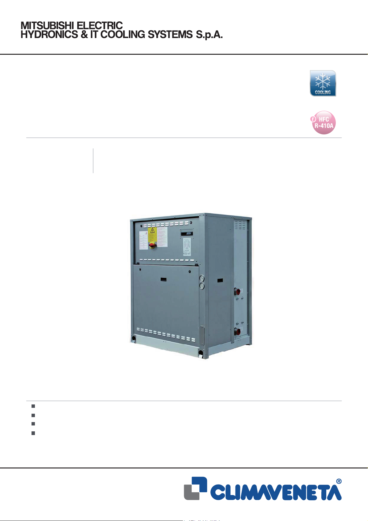
Condenserless chiller
Refrigerant gas R410A
Can be combined with a remote condenser
Integral control and adjustment
Integrated hydronic module
(The photo of the unit is indicative and may change depending on the model)
Page 2
CERTIFICATIONS
Product certifi cations
System certifi cations
Climaveneta S.p.A.:
Quality System complying with the requirements of UNI EN ISO9001:2008 regulation
Environmental Management System complying with the requirements of UNI EN
ISO14001:2004 regulation
Page 3

SUMMARY
NECS-ME
NECS-ME
0152 - 1604
1. Product presentation
1.1 NECS-ME units
1.2 R410A refrigerant
1.3 Combination with a remote condenser
1.4 Integral control and adjustment
1.5 Hydronic unit incorporated
1.6 Silent running
1.7 Ease of installation
1.8 Versatility
1.9 Usability
2. Unit description
2.1 Standard unit composition
2.2 Certifi cation, Reference standard
2.3 Tests
2.4 Controller
2.5 Accessories
2.6 Control unit with LCD display (standard)
3. Technical data
3.1 General technical data
3.2 Cooling capacity performance
4. Operating range
5. Hydraulic data
5.1 Water fl ow and pressure dro
5.2 Hydronic groups
6. Electrical data
7. Full load sound level
8. Dimensional drawings
9. Legend of pipe connections
10. Remote condensers
11. Combinations of evaporating units and remote condensers
pg. n° III
pg. n° III
pg. n° III
pg. n° III
pg. n° III
pg. n° III
pg. n° III
pg. n° III
pg. n° III
pg. n° III
pg. n° 1
pg. n° 1
pg. n° 1
pg. n° 1
pg. n° 2
pg. n° 2
pg. n° 3
pg. n° 5
pg. n° 5
pg. n° 8
pg. n° 13
pg. n° 14
pg. n° 14
pg. n° 15
pg. n° 19
pg. n° 20
pg. n° A1
pg. n° A6
pg. n° B1
pg. n° B2
The units highlighted in this publication contain HFC R410A [GWP
Liability disclaimer
This bulletin is not exhaustive about: installation, use, safety
precautions, handling and transport. Refer to “General Manual
for Installation” for further informations.
This bulletin refers to standard executions, in particular for
dimension, weight, electric, hydraulic, aeraulic and refrigerant connections (whereas applicable). Contact Climaveneta
Commercial Offi ce for further drawings and schemes.
2088] fluorinated greenhouse gases.
100
Climaveneta declines any liability derived from the bulletin’s
use.
This bulletin is of exclusive property of Climaveneta, and all
forms of copy are prohibited.
The data contained herein are subject to variation without notice.
II
NECS_ME_0152_1604_201004_GB
HFC R410A
Page 4

1. PRODUCT PRESENTATION
NECS-ME
Introduction
This section contains general information on the NECS-ME
range of products. For detailed information refer to the specifi c
sections in this bulletin.
1.1 NECS-ME units
The NECS-ME chillers are a range of remote-condensation liquid units running on R410A ecological gas.
They are indoor units with hermetic scroll compressors in a
single-circuit (2-compressor units) and twin-circuit (4-compressor unit) tandem confi guration, and braze-welded plate heat
exchangers.
1.2 R410A refrigerant
The use of R410A has improved the energy effi ciency of the
units, in full respect of the environment (O.D.P.=0)
1.3 Combination with a remote condenser
Compact units designed for residential and commercial systems.
1.4 Integral control and adjustment
The evaporating unit is supplied complete with integral microprocessor control and optional connection to a remote con-
denser.
1.5 Hydronic unit incorporated
The integrated hydronic unit comprises the main hydraulic
components; it is available in various confi gurations with single
or dual orthogonal pumps and high or low heads.
1.7 Ease of installation
All the connections of the NECS-ME units are located on the
side in order to simplify installation operations. This feature
also makes it possible to save space as the units can be positioned near the perimeter walls without compromising access
to the internal components during maintenance.
1.8 Versatility
On request, the NECS-ME units can be fi tted with an inte-
grated pump unit for circulating the liquid in the system, with
a high or low head depending on the various application requirements. As well as the primary pump, it is also possible to
add an auxiliary circulation pump which starts automatically if
the former develops a fault. This makes it possible to respect
the harshest safety aspects of the system, whilst allowing the
pumps to be rotated to balance operating hours (thus preventing risks of mechanical breakage) and to manually select one
of the two pumps.
1.9 Usability
The electronic controller of the NECS-ME features a programmable menu containing the most popular European languages
which the user can choose depending on the country in which
the unit is used (available standard in the 4-compressor unit, in
the reduced mode in the 2-compressor version).
1.6 Silent running
The NECS-ME chillers stand out for their silent running. If
specifi cally requested, the casing of the unit can incorporate
a layer of soundproofi ng made from high intermediate density
conoid sandwich material which reduces noise suffi ciently to
allow NECS-ME to be used in residential and commercial areas without having to install it in dedicated rooms (technical
rooms). The benefi t in terms of noise reduction is 4dB(A) in the
models with 2 compressors and 10dB(A) in the models with 4
compressors.
III
NECS_ME_0152_1604_201004_GB
HFC R410A
Page 5

2. UNIT DESCRIPTION
NECS-ME
Liquid chiller with remote condensation
Water-cooled indoor unit for producing chilled water, with connection to a remote condenser fi tted with hermetic rotary scroll
compressors running on R410A, braised-welded plate exchangers and a thermostatic expansion valve. Base and panelling in
hot-galvanised and painted sheet steel.
2.1 Standard unit composition
Structure
Base and frame in hot-galvanised shaped sheet steel with a
suitable thickness.
External panelling in PET-treated colaminate sheet, suitably
thick, built to allow total access to the internal components,
ventilation of the compressor chamber (standard for NECS-ME
0152..0612, option for all the other units). Acoustic insulation
of the panel with 30 mm thick Fiberform available as an accessory. Panels fi xed with metric screws (not self-tapping).
Refrigerant circuit
Main components of the refrigerant circuit:
- single-circuit unit with two compressors in a tandem confi gu-
ration (NECS-ME 0152..0612)
- twin-circuit unit with two compressors in a tandem confi gura-
tion on both circuits (NECS-ME 0612..1604)
- R410A refrigerant
- mechanical thermostatic valves
- dryer fi lter,
- refrigerant line sight glass with humidity indicator
- high pressure safety valve
- low pressure safety valve
- high and low pressure transducers
- high and low pressure gauges on all circuits (NECS-ME
0604..1604).
Compressor
Rotary hermetic scroll compressor in a tandem layout complete
with oil sump heater, electronic overheating protection with centralised manual reset and a two-pole electric motor.
- remote ON/OFF terminals
- spring terminals
- pump enable relays (only for units without a standard hydronic
unit)
- manual and automatic pump rotation system in case pumps
stop (only for units with a two-pump hydronic unit)
- automatic pump operation rotation system for balancing operating hours (only for units with a two-pump hydronic unit)
- terminals for cumulative alarm block (BCA)
- input voltage: 400V~ ±10% - 50Hz - 3N.
2.2 Certifi cation, Reference standards
The machine complies with the following directives and their
amendments:
- 2006/42/EC Machinery Directive.
- E.C.D. 89/336/EEC + 2004/108/EC.
- 2006/95/EC Low Voltage Directive.
- 97/23/EC Pressure Equipment Directive. Module A1. TÜVItalia 0948
2.3 Tests
Tests performed throughout the production process, as indicated in ISO9001. Performance or noise tests can be performed
by highly qualifi ed staff in the presence of customers.
Performance tests include the measurement of:
- electrical specifi cations
- water fl ow rates
- operating temperatures
- power input
- power output
- pressure drops on the water side exchanger both at full load
(at selection conditions and at the most critical conditions for
the condenser) and at part load conditions.
During performance testing the main alarm states can also be
simulated.
Noise tests are performed to check noise emissions according
to ISO3744.
User side exchanger
AISI 316 steel braze-welded plate exchanger. The heat exchanger is insulated with a closed-cell condensation proof
lining in neoprene. When the unit is working, it is protected
against lack of fl ow by a differential pressure switch mounted
on the water side. The unit can work with antifreeze mixtures at
exchanger outlet temperatures as low as -8°C.
Electric power and control panel
Electric power and control panel, built to EN 60204-1/EC 204-1
standards, complete with:
- control circuit transformer,
- general door lock isolator,
- fuses and contactors for compressors (NECS-ME
0604..1604)
- circuit breakers on loads (NECS-ME 0152..0612)
- numbered electric cables (NECS-ME 0152..0612)
- auxiliary signal 4..2OmA for unit operating setpoint offset
(NECS-ME 0604..1604)
- Keyboard with multi-language interface and LCD display
(NECS-ME 0604..1604)
1
NECS_ME_0152_1604_201004_GB
HFC R410A
Page 6

NECS-ME
2.4 Controller
The controller is available in two formats:
- W3000 Base: keyboard and LED display.
- W3000SE Compact: the keypad features functional controls
and a complete LCD display that allows assessment and intervention on the unit by means of a multi-level menu with selectable user’s language.
The diagnostics comprises a complete alarm management system, including “black box” (via PC) functions and an alarm log
(via display or also PC) for optimised analysis of unit performance.
Compatibility with the remote keyboard managing up to 10
units.
The presence of the programmable timer allows the creation
of an operating profi le containing up to 4 typical days and 10
time bands.
Common features: Heat adjustment is based on the exclusive
QuickMind algorithm, featuring a self-adaptive logic which is
useful for systems with a low water content. Alternatively, proportional or proportional-integral adjustments can be set.
For systems featuring more than one unit, the resources can
be adjusted using optional propriety devices. Consumption and
performance accounting can also be implemented. Supervision
can be easily developed via proprietary devices or the integration in third party systems by means of the most common protocols as ModBus, Bacnet, Bacnet-over-IP, Echelon LonWorks
protocols.
2.5 Accessories
- Soft start
Electronic device adopted to manage the inrush current.
Break down of the inrush current as soon as the electrical motor is switch on, lower motor’s mechanical wear, favourable
sizing for the electrical system.
- HP and LP gauges
High and low pressure gauges (only for sizes 0152..0612).
Allows immediate reading of the pressure values on both low
and high pressure circuits.
- Compressor suction valve
Shut-off solenoid valve on compressor’s suction circuit.
Simplifi es maintenance activities.
- Compr. discharge line valve
Shut-off solenoid valve on compressor discharge circuit.
Simplifi es maintenance activities.
- Extra insulation for the compressors section
Acoustic encolsure on both compressor and pump sections
(when applicable).
Noise emission reduction.
- Automatic circuit breakers
Over-current switch on the major electrical loads.
It protects compressors and/or fans from possible current
peaks.
- Input remote demand limit
Digital input (voltage free)
It permits to limit the unit’s power absorption for safety reasons or in temporary situation.
- Liquid line solenoid valve
Solenoid valve on the refrigerant circuit inlet (only for sizes
0604..1604).
It avoids liquid to migrate toward the compressors when they
are off.
- Remote phase-sequence control
Relay for controlling the phase-sequence of mains.
Protects loads against faults due to incorrect connection of
the electric line.
- Compressors’ on/off signal
Auxiliary contacts providing a voltage-free signal.
Allows remote signalling of compressor’s activation or remote
control of any auxiliary loads.
- ModBUS connectivity
Interface module for ModBUS protocols.
Allows integration with BMS operating with ModBUS protocol.
- BACnet connectivity
Interface module for BACnet protocols.
Allows integration with BMS operating with BACnet protocol.
- Echelon connectivity
Interface module for Echelon systems.
Allows integration with BMS operating with Echelon procotls.
- Auxiliary signal 4-20mA
4..20mA analogue input. Allows to change the operating setpoint according to the value of current applied to the analogue
input.
Enforce Energy Saving policies
- Multi-units control devices
(Sequencer, Manager3000, FWS3000)
Separately supplied.
2
NECS_ME_0152_1604_201004_GB
HFC R410A
Page 7
NECS-ME
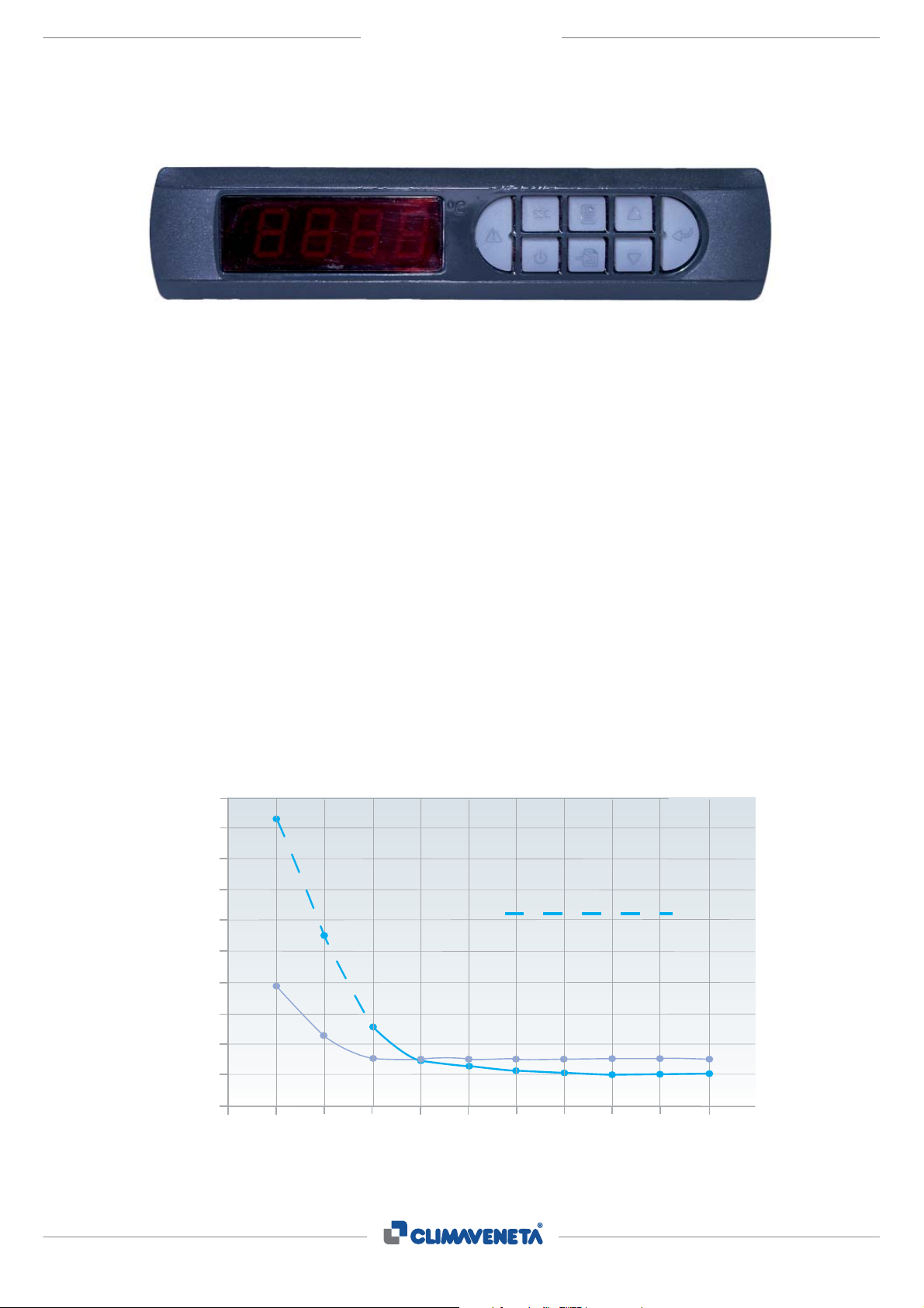
2.6 Control unit with LCD display (standard)
The new “W3000 Base” control unit is installed on all NECS-ME
0152..0612 units.
The new “W3000SE Compact” control unit is installed on all
NECS-ME 0604..1604 units.
Main functions: QuickMind, local and remote FWS supervision, dual set point management, etc, confi rm Climaveneta’s
commitment to continually developing its electronics technology.
The heat pumps, moreover, are fi tted with the original Cli-
maveneta defrosting control system called “Autotuning Defrost”
which considerably reduces defrosting times, thus improving
the energy performance of the unit. Interfaces with BMS systems: METASYS®, MODBUS®, LONWORKS®, SIEMENS®,
TREND®.
Black Box logs data relative to 200 alarm events which can be
printed with a personal computer.
Variation output temperature
12
11
10
9
8
7
6
5
Temperatura in uscita (°C)
4
Output temperature (°C)
3
2
0.5 1.5 2.5 3.5 4.5 5.5 6.5 7.5 8.5 9.5
11.34
Step-wise regulation
Regolazione a gradini
7.54
Quickmind
5.9
4.3
Variazione temperatura in uscita
4.56
3,68
3.9
3.5
Minimum water content in the plant lt/kW
QuickMind is a special control unit which monitors the main
operating parameters, predicts system behaviour and anticipates unit settings in order to constantly optimise performance;
it allows both return and delivery water temperatures to be
chosen as adjustment parameters. It can reduce outlet temperature fl uctuations even with a small amount of water in
the system. When, for dual-compressor chillers featuring a
maximum of 12 start-ups per hour and using a traditional adjustment system, the minimum recommended water content
is 5.5 l/kW. QuickMind ensures the same chiller operates correctly even with a water content of just 2.5 l/kW and considerably reduces outlet temperature fl uctuations. The above graph
shows that outlet temperature fl uctuations with QuickMind are
limited to 4.3 °C as opposed to 7.54°C if the traditional adjustment system were used, without even ensuring an acceptable
minimum compressor start time.
Not acceptable minimum starting time compressors
Tempo minimo di accensione compressore non accettabile
3.52
3.3
3.52
3.2
3.52 3.52
3.1
3.52
3
3.52
10.5
3
11
3
3
NECS_ME_0152_1604_201004_GB
HFC R410A
Page 8
NECS-ME
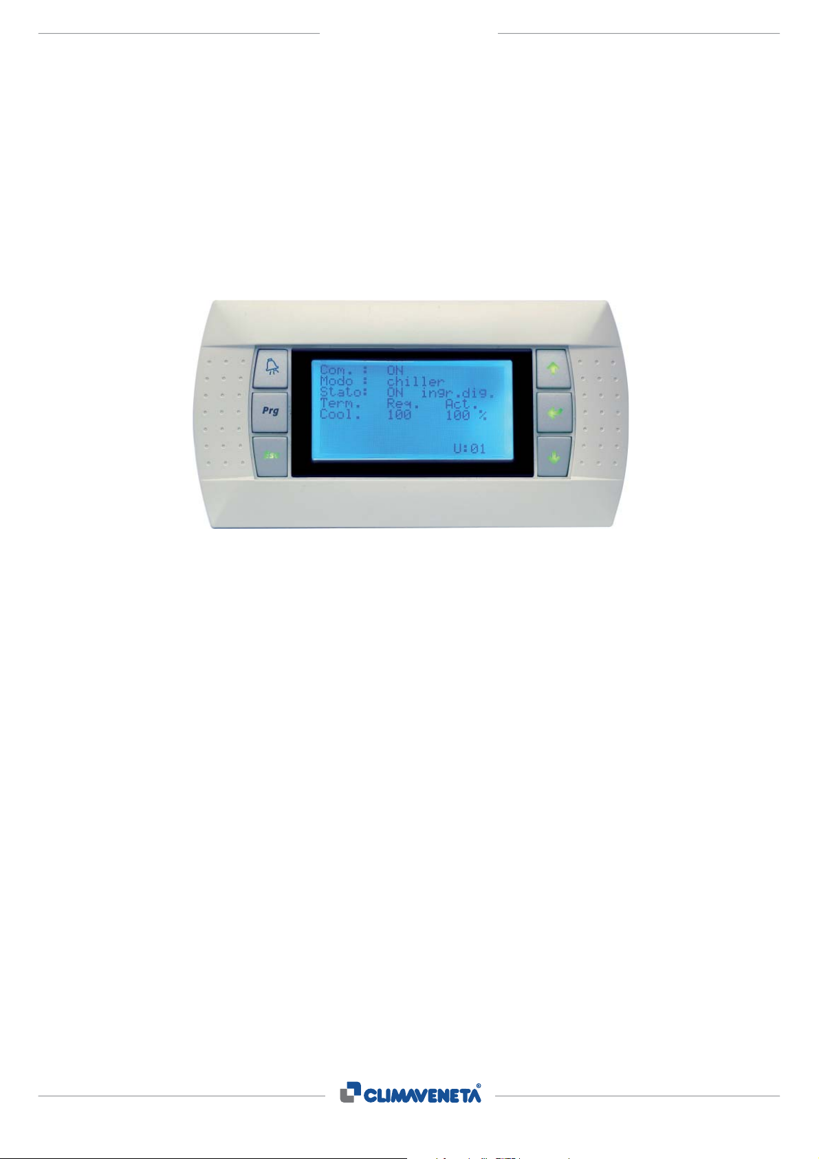
Control unit with LCD display
(optional for NECS-ME 0152..0612)
Remote keyboard
As an alternative to the standard keyboard, the NECS has
a W3000 Compact operator panel with liquid crystal display.
(LCD)
This keyboard is standard for the NECS-ME 0604..1604 units.
This keyboard features a user interface for 3 European languages that can be selected by the user. Two of these are
preset (Italian and English) and the third can be chosen from
French, German, Spanish, Swedish and Russian (to specify
when ordering). This allows the control unit interface to be chosen to suit the country of destination or, thanks to English, to be
completely independent for all geographical areas.
This same type of operator panel is also available as a remote
keyboard, to be connected to the unit by means of a serial connection up to a maximum distance of 200 metres without power
supply (in this case power is supplied by the unit), or a maximum of 500 metres with dedicated local power supply.
Note
The remote keyboard may be connected to the unit without replacing the W3000 Base operator panel originally provided on
the unit. In this case the interface fi tted locally on the unit is ex-
cluded, and access to the programming menus and the display
of the machine status is present only the additional keyboard at
remote level.
Instead, when the W3000 Base operator panel is replaced with
the W3000 Compact panel, control of the unit is possible at
both local and remote level. In this case the remote keyboard
faithfully reproduces what is shown on the control unit on board
the machine, further facilitating all the operations of confi guring
and controlling the unit.
4
NECS_ME_0152_1604_201004_GB
HFC R410A
Page 9

3.1 GENERAL TECHNICAL DATA
NECS-ME
B
SIZE 0152 0182 0202 0252 0262 0302 0352
NECS-ME /B
COOLING
(1)
Cooling capacity kW 39,5 45,8 53,6 60,5 67,4 80,2 92,8
Total power input (unit) kW 12,0 13,5 15,7 18,1 20,0 23,4 26,9
EER
ESEER
3,29
-
3,39
-
3,41
-
3,34 - 3,37
-
3,43
-
3,45
Heat exchanger water flow m³/h 6,80 7,89 9,23 10,4 11,6 13,8 16,0
Heat exchanger pressure drop kPa 48,0 41,3 41,0 39,1 48,4 29,4 27,6
COMPRESSORS
Number
Number of capacity
Number of circuits N°.
Type of regulation
N°. 2 2 2 2 2 2 2
N°.
2 2 2 2 2 2 2
1 1 1 1 1 1 1
STEPS STEPS STEPS STEPS STEPSSTEPSSTEPS
% 50 50 50 50 50 50 50Minimum capacity steps
R410AR410AR410A R410A R410AR410AR410AType of refrigerant
mm.
mm.
mm.
kg.
(2)
74
75
76
4443
(3)
1130
669
1255
270
1130
669
1255
280
1130
669
1255
290
1130
669
1255
295
1130
669
1255
300
1310
893
1496
410
77
4544 434342dB(A)Total sound pressure
1310
893
1496
500
NOISE LEVELS
Total sound power dB(A) 73 74 74
DIMENSIONS AND WEIGHTS
Length
Width
Height
Weight
-
--- - ---kg.Refrigerant charge
333 3 333kg.Oil charge
1 Plant (side) cooling exchanger water (in/out) 12/7 °C
Condensation temperature 47 °C
2 Sound power on the basis of measurements made in compliance with ISO 9614 and Eurovent 8/1 for Eurovent certified units;
in compliance with ISO 3744 for non-certified units
Average sound pressure level, at 10 (m.) distance, unit in a free field on a reflective surface; non-binding value obtained
from the sound power level
3 Standard configuration
- Not available
ELCADOC - Ver. 1.0.0.1
5
NECS-ME_0152_1604_201004_*% Ref.: R410A
Page 10
GENERAL TECHNICAL DATA
NECS-ME
B
SIZE 0412 0452 0512 0552 0612 0604 0704
NECS-ME /B
COOLING
(1)
Cooling capacity kW 105 117 131 151 170 161 186
Total power input (unit) kW 30,3 33,9 37,6 43,3 48,9 46,9 53,7
EER
ESEER
3,45
-
3,46
-
3,49
-
3,48 - 3,47
-
3,43
-
3,46
Heat exchanger water flow m³/h 18,0 20,2 22,6 25,9 29,3 27,7 31,9
Heat exchanger pressure drop kPa 35,0 33,1 32,2 28,9 36,8 32,5 31,0
COMPRESSORS
Number
Number of capacity
Number of circuits N°.
Type of regulation
N°. 2 2 2 2 2 4 4
N°.
2 2 2 2 2 4 4
1 1 1 1 1 2 2
STEPS STEPS STEPS STEPS STEPSSTEPSSTEPS
% 50 50 50 50 50 25 25Minimum capacity steps
R410AR410AR410A R410A R410AR410AR410AType of refrigerant
3,253,256 7 755kg.Oil charge
mm.
mm.
mm.
kg.
(2)
79
79
86
5447
(3)
1310
893
1496
585
1310
893
1496
615
1310
893
1496
645
1310
893
1496
680
1310
893
1496
755
2227
1020
1780
700
87
5547 464645dB(A)Total sound pressure
2227
1020
1780
950
NOISE LEVELS
Total sound power dB(A) 77 78 78
DIMENSIONS AND WEIGHTS
Length
Width
Height
Weight
-
--- - ---kg.Refrigerant charge
1 Plant (side) cooling exchanger water (in/out) 12/7 °C
Condensation temperature 47 °C
2 Sound power on the basis of measurements made in compliance with ISO 9614 and Eurovent 8/1 for Eurovent certified units;
in compliance with ISO 3744 for non-certified units
Average sound pressure level, at 10 (m.) distance, unit in a free field on a reflective surface; non-binding value obtained
from the sound power level
3 Standard configuration
- Not available
ELCADOC - Ver. 1.0.0.1
6
NECS-ME_0152_1604_201004_*% Ref.: R410A
Page 11

GENERAL TECHNICAL DATA
NECS-ME
B
SIZE 0804 0904 1004 1104 1204 1404 1604
NECS-ME /B
COOLING
(1)
Cooling capacity kW 207 235 263 301 339 387 432
Total power input (unit) kW 60,6 67,9 75,2 86,5 97,8 111 124
EER
ESEER
3,42
-
3,47
-
3,50
-
3,47 - 3,47
-
3,49
-
3,48
Heat exchanger water flow m³/h 35,7 40,5 45,3 51,7 58,4 66,5 74,3
Heat exchanger pressure drop kPa 38,8 38,9 39,4 36,7 46,7 49,6 54,7
COMPRESSORS
Number
Number of capacity
Number of circuits N°.
Type of regulation
N°. 4 4 4 4 4 4 4
N°.
4 4 4 4 4 4 4
2 2 2 2 2 2 2
STEPS STEPS STEPS STEPS STEPSSTEPSSTEPS
% 25 25 25 25 25 25 25Minimum capacity steps
R410AR410AR410A R410A R410AR410AR410AType of refrigerant
6,36,36,3 6,8 6,84,74,7kg.Oil charge
mm.
mm.
mm.
kg.
(2)
91
91
91
5959
(3)
2227
1020
1780
1125
2227
1020
1780
1185
2227
1020
1780
1250
2227
1020
1780
1330
2227
1020
1780
1370
2227
1020
1780
1430
91
5959 585756dB(A)Total sound pressure
2227
1020
1780
1480
NOISE LEVELS
Total sound power dB(A) 88 89 90
DIMENSIONS AND WEIGHTS
Length
Width
Height
Weight
-
--- - ---kg.Refrigerant charge
1 Plant (side) cooling exchanger water (in/out) 12/7 °C
Condensation temperature 47 °C
2 Sound power on the basis of measurements made in compliance with ISO 9614 and Eurovent 8/1 for Eurovent certified units;
in compliance with ISO 3744 for non-certified units
Average sound pressure level, at 10 (m.) distance, unit in a free field on a reflective surface; non-binding value obtained
from the sound power level
3 Standard configuration
- Not available
ELCADOC - Ver. 1.0.0.1
7
NECS-ME_0152_1604_201004_*% Ref.: R410A
Page 12

3.2 COOLING CAPACITY PERFORMANCE
NECS-ME
B
0152
Tc
Pf
Pat
Qev
Dpev
Pf 50,0 48,0 45,8 43,3 40,5 37,4 51,4 49,5 47,2 44,7 41,8 38,7 52,8 50,9 48,7 46,1 43,2 39,9
Pat 8,15 9,11 10,2 11,5 12,9 14,5 8,18 9,13 10,2 11,5 12,9 14,5 8,20 9,15 10,3 11,5 12,9 14,5
Qev 8,60 8,27 7,89 7,46 6,98 6,44 8,85 8,52 8,14 7,70 7,21 6,66 9,10 8,77 8,39 7,94 7,44 6,88
Dpev 76,8 71,0 64,6 57,7 50,5 43,1 81,3 75,3 68,7 61,5 53,9 46,0 85,9 79,8 73,0 65,4 57,4 49,1
45,6 43,7 41,6 39,2 36,6 33,7 47,1 45,2 43,0 40,6 37,9 34,9 48,5 46,6 44,4 41,9 39,2 36,2
8,07 9,04 10,2 11,5 12,9 14,5 8,10 9,06 10,2 11,5 12,9 14,5 8,13 9,09 10,2 11,5 12,9 14,5
7,86 7,53 7,16 6,74 6,29 5,80 8,11 7,78 7,40 6,98 6,52 6,01 8,36 8,02 7,65 7,22 6,75 6,23
64,0 58,7 53,1 47,2 41,0 34,8 68,1 62,7 56,8 50,6 44,1 37,5 72,4 66,8 60,6 54,1 47,2 40,2
35 40 45 50 55 30 30 35 40 45 50 55 30 35 40 45 50 55
6 7 8 Tev
9 10 11 Tev
0182
Tc
Pf
Pat
Qev
Dpev
Pf 58,3 55,6 52,8 50,0 47,2 44,2 60,0 57,3 54,4 51,6 48,7 45,7 61,8 58,9 56,0 53,1 50,2 47,2
Pat 9,29 10,4 11,6 13,0 14,4 16,0 9,33 10,4 11,6 13,0 14,4 16,0 9,36 10,5 11,7 13,0 14,4 16,0
Qev 10,0 9,57 9,10 8,61 8,12 7,62 10,3 9,86 9,38 8,88 8,38 7,88 10,7 10,2 9,66 9,15 8,65 8,14
Dpev 66,8 60,8 55,0 49,3 43,8 38,6 71,0 64,6 58,4 52,4 46,7 41,2 75,4 68,5 61,9 55,6 49,7 44,0
52,9 50,5 48,0 45,4 42,7 39,8 54,7 52,2 49,6 46,9 44,1 41,3 56,5 53,9 51,2 48,5 45,7 42,8
9,18 10,3 11,5 12,9 14,3 15,9 9,22 10,3 11,6 12,9 14,4 15,9 9,26 10,4 11,6 12,9 14,4 16,0
9,11 8,70 8,27 7,81 7,34 6,85 9,42 8,99 8,54 8,08 7,60 7,11 9,73 9,28 8,82 8,35 7,86 7,36
55,1 50,2 45,4 40,5 35,8 31,2 58,9 53,6 48,4 43,3 38,4 33,5 62,8 57,2 51,6 46,3 41,0 36,0
35 40 45 50 55 30 30 35 40 45 50 55 30 35 40 45 50 55
6 7 8 Tev
9 10 11 Tev
0202
Tc
Pf
Pat
Qev
Dpev
Pf 67,6 65,0 62,1 58,7 54,9 50,8 69,5 66,9 64,0 60,6 56,7 52,5 71,5 68,9 65,9 62,4 58,5 54,3
Pat 10,7 12,0 13,4 15,1 16,9 18,9 10,7 12,0 13,4 15,1 16,9 18,9 10,8 12,0 13,4 15,1 16,9 18,9
Qev 11,6 11,2 10,7 10,1 9,46 8,74 12,0 11,5 11,0 10,4 9,77 9,04 12,3 11,9 11,3 10,8 10,1 9,35
Dpev 65,1 60,3 55,0 49,2 43,1 36,8 69,0 64,0 58,4 52,3 45,9 39,3 72,9 67,7 61,9 55,6 49,0 42,0
61,7 59,3 56,4 53,2 49,6 45,6 63,7 61,2 58,3 55,0 51,4 47,3 65,6 63,1 60,2 56,9 53,1 49,0
10,6 11,9 13,3 15,0 16,9 18,9 10,6 11,9 13,4 15,0 16,9 18,9 10,7 11,9 13,4 15,0 16,9 18,9
10,6 10,2 9,71 9,15 8,53 7,85 11,0 10,5 10,0 9,47 8,84 8,15 11,3 10,9 10,4 9,79 9,15 8,44
54,3 50,0 45,3 40,3 35,0 29,7 57,8 53,3 48,4 43,1 37,6 31,9 61,4 56,8 51,6 46,1 40,3 34,3
35 40 45 50 55 30 30 35 40 45 50 55 30 35 40 45 50 55
6 7 8 Tev
9 10 11 Tev
0252
Tc
Pf
Pat
Qev
Dpev
Pf
Pat 12,7 14,0 15,6 17,3 19,3 21,5 12,7 14,0 15,6 17,3 19,3 21,5 12,8 14,1 15,6 17,3 19,3 21,5
Qev
Dpev 61,9 57,5 52,4 46,9 41,1 35,0 65,6 61,0 55,8 50,0 43,8 37,3 69,4 64,7 59,3 53,2 46,6 39,7
69,5 66,7 63,6 60,0 56,1 51,7 71,7 68,9 65,7 62,1 58,0 53,6 73,9 71,1 67,9 64,2 60,0 55,4
12,5 13,9 15,5 17,3 19,3 21,5 12,6 13,9 15,5 17,3 19,3 21,5 12,6 14,0 15,5 17,3 19,3 21,5
12,0 11,5 10,9 10,3 9,65 8,91 12,3 11,9 11,3 10,7 9,99 9,22 12,7 12,3 11,7 11,1 10,3 9,54
51,5 47,5 43,1 38,4 33,5 28,6 54,9 50,7 46,1 41,1 36,0 30,6 58,4 54,0 49,2 44,0 38,5 32,8
76,2 73,4 70,1 66,3 62,0 57,2 78,4 75,6 72,3 68,4 64,0 59,1 80,6 77,8 74,5 70,5 66,0 60,9
13,1 12,6 12,1 11,4 10,7 9,86 13,5 13,0 12,4 11,8 11,0 10,2 13,9 13,4 12,8 12,2 11,4 10,5
35 40 45 50 55 30 30 35 40 45 50 55 30 35 40 45 50 55
6 7 8 Tev
9 10 11 Tev
0262
Tc
Pf
Pat
Qev
Dpev
Pf 84,9 81,4 77,6 73,5 69,1 64,4 87,4 83,9 80,0 75,8 71,3 66,4 90,0 86,3 82,3 78,0 73,4 68,5
Pat 14,2 15,7 17,3 19,2 21,4 23,8 14,3 15,7 17,4 19,3 21,4 23,8 14,3 15,8 17,4 19,3 21,5 23,9
Qev 14,6 14,0 13,4 12,7 11,9 11,1 15,1 14,4 13,8 13,1 12,3 11,4 15,5 14,9 14,2 13,4 12,7 11,8
Dpev 76,9 70,7 64,3 57,7 51,0 44,3 81,7 75,1 68,3 61,3 54,3 47,2 86,6 79,7 72,5 65,1 57,6 50,2
77,3 74,1 70,6 66,8 62,7 58,3 79,8 76,5 72,9 69,0 64,8 60,3 82,3 78,9 75,2 71,2 66,9 62,4
14,0
13,3 12,8 12,1 11,5 10,8 10,0 13,7 13,2 12,5 11,9 11,2 10,4 14,2 13,6 13,0 12,3 11,5 10,7
63,8
35 40 45 50 55 30 30 35 40 45 50 55 30 35 40 45 50 55
6 7 8 Tev
15,5 17,1 19,1 21,2 23,6 14,1 15,5 17,2 19,1 21,3 23,7 14,2 15,6 17,3 19,2 21,4 23,8
58,5 53,1 47,5 41,9 36,3 68,0 62,5 56,7 50,8 44,8 38,8 72,4 66,5 60,4 54,2 47,8 41,5
9 10 11 Tev
Tc [°C] - Condensation temperature
Tev [°C] - Plant (side) cooling exchanger output water temperature
Pf [kW] - Cooling capacity
Pat [kW] - Total power input
Qev [m³/h] - Plant (side) heat exchanger water flow
Dpev [kPa] - Plant (side) cooling exchanger pressure drop
'-' Conditions outside the operating range
Waterflow and pressure drop on heat exchangers calculated with 5°C of delta T
ELCADOC - Ver. 1.0.0.1
8
NECS-ME_0152_1604_201004_*% Ref.: R410A
Page 13

COOLING CAPACITY PERFORMANCE
NECS-ME
B
0302
Tc
Pf
Pat
Qev
Dpev
Pf 101 96,9 92,4 87,5 82,4 77,0 104 99,9 95,2 90,3 85,0 79,4 107 103 98,1 93,0 87,6 81,9
Pat 16,8 18,5 20,5 22,7 25,0 27,6 16,8 18,6 20,5 22,7 25,1 27,7 16,8 18,6 20,6 22,8 25,1 27,7
Qev 17,4 16,7 15,9 15,1 14,2 13,3 18,0 17,2 16,4 15,5 14,6 13,7 18,5 17,7 16,9 16,0 15,1 14,1
Dpev 46,8 42,9 39,0 35,0 31,0 27,1 49,7 45,6 41,5 37,2 33,0 28,8 52,8 48,4 44,0 39,5 35,1 30,6
92,0 88,1 83,9 79,5 74,7 69,7 95,0 91,0 86,7 82,1 77,3 72,1 98,1 94,0 89,5 84,8 79,8 74,5
16,6 18,3 20,3 22,4 24,8 27,4 16,6 18,4 20,3 22,5 24,9 27,5 16,7 18,5 20,4 22,6 25,0 27,5
15,8 15,2 14,4 13,7 12,9 12,0 16,4 15,7 14,9 14,1 13,3 12,4 16,9 16,2 15,4 14,6 13,7 12,8
38,6 35,4 32,1 28,8 25,5 22,2 41,2 37,8 34,3 30,8 27,3 23,7 43,9 40,3 36,6 32,9 29,1 25,4
35 40 45 50 55 30 30 35 40 45 50 55 30 35 40 45 50 55
6 7 8 Tev
9 10 11 Tev
0352
Tc
Pf
Pat
Qev
Dpev
Pf 118 113 107 102 95,4 89,0 122 117 111 105 98,5 92,0 126 120 114 108 102 95,0
Pat 19,5 21,3 23,5 26,0 28,8 31,8 19,5 21,4 23,6 26,1 28,8 31,9 19,6 21,5 23,6 26,1 28,9 32,0
Qev 20,4 19,5 18,5 17,5 16,4 15,3 21,0 20,1 19,1 18,0 17,0 15,8 21,7 20,7 19,7 18,6 17,5 16,4
Dpev 44,8 40,9 36,9 33,0 29,2 25,4 47,7 43,5 39,3 35,2 31,1 27,1 50,7 46,2 41,8 37,4 33,1 28,9
107 102 97,3 91,9 86,2 80,2 111 106 101 95,1 89,2 83,1 115 109 104 98,3 92,3 86,0
19,2 21,1 23,2 25,7 28,5 31,5 19,3 21,2 23,3 25,8 28,6 31,6 19,4 21,3 23,4 25,9 28,7 31,7
18,5 17,6 16,8 15,8 14,8 13,8 19,1 18,2 17,3 16,4 15,4 14,3 19,7 18,8 17,9 16,9 15,9 14,8
36,8 33,6 30,3 27,0 23,8 20,6 39,4 35,9 32,4 28,9 25,5 22,1 42,0 38,4 34,6 30,9 27,3 23,7
35 40 45 50 55 30 30 35 40 45 50 55 30 35 40 45 50 55
6 7 8 Tev
9 10 11 Tev
0412
Tc
Pf
Pat
Qev
Dpev
Pf 134 128 121 115 108 100 138 132 125 118 111 104 143 136 129 122 115 107
Pat 22,2 24,1 26,5 29,3 32,5 36,0 22,3 24,2 26,6 29,4 32,6 36,1 22,3 24,3 26,7 29,5 32,6 36,2
Qev 23,1 22,0 20,9 19,7 18,5 17,3 23,8 22,7 21,6 20,4 19,2 17,9 24,6 23,4 22,2 21,0 19,8 18,5
Dpev 57,6 52,4 47,2 42,1 37,1 32,2 61,3 55,8 50,3 44,9 39,6 34,5 65,2 59,3 53,5 47,8 42,3 36,9
122 116 110 104 96,9 90,0 126 120 114 107 100 93,4 130 124 118 111 104 96,8
21,9 23,8 26,2 29,0 32,1 35,7 22,0 23,9 26,3 29,1 32,2 35,8 22,1 24,0 26,4 29,2 32,4 35,9
20,9 19,9 18,9 17,8 16,7 15,5 21,6 20,6 19,6 18,5 17,3 16,1 22,4 21,3 20,2 19,1 17,9 16,7
47,3 43,0 38,6 34,3 30,1 25,9 50,6 46,0 41,4 36,8 32,3 27,9 54,0 49,1 44,2 39,4 34,6 30,0
35 40 45 50 55 30 30 35 40 45 50 55 30 35 40 45 50 55
6 7 8 Tev
9 10 11 Tev
0452
Tc
Pf
Pat
Qev
Dpev
Pf
Pat 24,7 27,0 29,7 32,8 36,3 40,2 24,8 27,1 29,8 32,9 36,4 40,3 24,9 27,2 29,9 33,0 36,5 40,4
Qev
Dpev 53,5 49,0 44,3 39,6 34,9 30,3 56,9 52,1 47,2 42,2 37,3 32,4 60,4 55,3 50,1 44,9 39,7 34,5
136 130 123 116 109 101 140 134 127 120 113 105 145 138 132 124 117 109
24,4 26,7 29,3 32,4 36,0 39,9 24,5 26,8 29,5 32,6 36,1 40,0 24,6 26,9 29,6 32,7 36,2 40,1
23,3 22,3 21,2 20,0 18,8 17,4 24,1 23,1 21,9 20,7 19,4 18,0 24,9 23,8 22,7 21,4 20,1 18,7
44,1 40,3 36,4 32,5 28,5 24,6 47,1 43,1 38,9 34,7 30,5 26,4 50,2 46,0 41,6 37,1 32,7 28,3
149 143 136 128 121 112 154 147 140 133 125 116 158 152 144 137 128 120
25,7 24,6 23,4 22,1 20,8 19,3 26,5 25,4 24,1 22,8 21,4 20,0 27,3 26,1 24,9 23,5 22,1 20,6
35 40 45 50 55 30 30 35 40 45 50 55 30 35 40 45 50 55
6 7 8 Tev
9 10 11 Tev
0512
Tc
Pf
Pat
Qev
Dpev
Pf 166 159 152 144 135 125 171 164 157 148 139 129 176 169 161 153 144 134
Pat 27,3 29,9 32,9 36,3 40,2 44,4 27,4 30,0 33,0 36,4 40,2 44,4 27,5 30,1 33,1 36,5 40,3 44,5
Qev 28,6 27,4 26,1 24,7 23,2 21,6 29,5 28,3 27,0 25,5 24,0 22,3 30,4 29,1 27,8 26,3 24,7 23,0
Dpev 51,6 47,4 43,1 38,6 34,0 29,4 54,8 50,4 45,8 41,1 36,2 31,3 58,1 53,5 48,7 43,7 38,5 33,4
151 145 138 130 122 113 156 150 142 135 126 117 161 154 147 139 131 121
26,9
26,0 24,9 23,7 22,4 21,0 19,5 26,9 25,7 24,5 23,2 21,7 20,2 27,7 26,6 25,3 24,0 22,5 20,9
42,6
35 40 45 50 55 30 30 35 40 45 50 55 30 35 40 45 50 55
6 7 8 Tev
29,5 32,5 36,0 39,8 44,1 27,1 29,6 32,7 36,1 39,9 44,2 27,2 29,8 32,8 36,2 40,1 44,3
39,1 35,4 31,6 27,8 24,0 45,5 41,8 37,9 33,9 29,8 25,7 48,5 44,5 40,4 36,2 31,8 27,5
9 10 11 Tev
Tc [°C] - Condensation temperature
Tev [°C] - Plant (side) cooling exchanger output water temperature
Pf [kW] - Cooling capacity
Pat [kW] - Total power input
Qev [m³/h] - Plant (side) heat exchanger water flow
Dpev [kPa] - Plant (side) cooling exchanger pressure drop
'-' Conditions outside the operating range
Waterflow and pressure drop on heat exchangers calculated with 5°C of delta T
ELCADOC - Ver. 1.0.0.1
9
NECS-ME_0152_1604_201004_*% Ref.: R410A
Page 14

COOLING CAPACITY PERFORMANCE
NECS-ME
B
0552
Tc
Pf
Pat
Qev
Dpev
Pf 191 183 174 165 155 144 197 189 180 170 160 149 203 194 185 175 165 153
Pat 31,4 34,4 37,8 41,8 46,2 51,2 31,5 34,5 38,0 41,9 46,3 51,2 31,6 34,6 38,1 42,0 46,4 51,3
Qev 32,9 31,5 30,0 28,4 26,6 24,8 33,9 32,5 31,0 29,3 27,5 25,6 34,9 33,5 31,9 30,2 28,4 26,4
Dpev 46,5 42,7 38,7 34,6 30,5 26,4 49,4 45,4 41,2 36,9 32,5 28,2 52,4 48,2 43,8 39,2 34,6 30,0
174 166 158 149 140 130 179 172 163 154 145 135 185 177 169 160 150 139
31,0 33,9 37,4 41,4 45,8 50,8 31,1 34,1 37,6 41,5 46,0 50,9 31,3 34,2 37,7 41,7 46,1 51,0
29,9 28,6 27,2 25,7 24,1 22,4 30,9 29,6 28,1 26,6 24,9 23,2 31,9 30,5 29,1 27,5 25,8 24,0
38,4 35,1 31,8 28,4 24,9 21,5 41,0 37,5 34,0 30,4 26,7 23,1 43,7 40,1 36,3 32,5 28,6 24,7
35 40 45 50 55 30 30 35 40 45 50 55 30 35 40 45 50 55
6 7 8 Tev
9 10 11 Tev
0612
Tc
Pf
Pat
Qev
Dpev
Pf 216 206 197 186 175 162 222 213 203 192 180 168 229 219 209 198 186 173
Pat 35,5 38,9 42,8 47,3 52,3 57,9 35,6 39,0 42,9 47,4 52,4 58,1 35,8 39,1 43,0 47,5 52,6 58,2
Qev 37,1 35,6 33,9 32,0 30,1 28,0 38,3 36,7 34,9 33,1 31,0 28,9 39,5 37,8 36,0 34,1 32,0 29,9
Dpev 59,3 54,4 49,3 44,1 38,9 33,7 63,1 57,9 52,5 47,0 41,5 35,9 67,0 61,5 55,8 50,0 44,1 38,3
196 187 178 168 158 147 202 194 184 174 163 152 209 200 190 180 169 157
35,0 38,4 42,3 46,8 51,8 57,4 35,2 38,5 42,5 47,0 52,0 57,6 35,3 38,7 42,6 47,1 52,2 57,8
33,7 32,3 30,7 29,0 27,2 25,2 34,9 33,4 31,7 30,0 28,1 26,2 36,0 34,5 32,8 31,0 29,1 27,1
48,9 44,7 40,4 36,1 31,7 27,4 52,3 47,8 43,3 38,7 34,0 29,4 55,7 51,0 46,2 41,3 36,4 31,5
35 40 45 50 55 30 30 35 40 45 50 55 30 35 40 45 50 55
6 7 8 Tev
9 10 11 Tev
0604
Tc
Pf
Pat
Qev
Dpev
Pf 203 194 185 176 165 154 209 200 191 181 170 159 216 206 197 186 176 164
Pat 33,5 37,0 41,0 45,3 50,1 55,2 33,6 37,1 41,1 45,4 50,2 55,3 33,7 37,2 41,2 45,5 50,3 55,4
Qev 35,0 33,5 31,9 30,2 28,5 26,6 36,1 34,5 32,9 31,2 29,4 27,4 37,1 35,6 33,9 32,1 30,3 28,3
Dpev 51,8 47,5 43,2 38,7 34,3 29,9 55,1 50,5 45,9 41,2 36,5 31,9 58,5 53,7 48,7 43,8 38,8 33,9
184 177 168 159 150 140 191 183 174 165 155 145 197 188 180 170 160 149
33,2 36,6 40,5 44,9 49,6 54,8 33,3 36,8 40,7 45,0 49,8 55,0 33,4 36,9 40,8 45,2 49,9 55,1
31,7 30,4 29,0 27,4 25,8 24,0 32,8 31,4 29,9 28,4 26,7 24,9 33,9 32,4 30,9 29,3 27,6 25,7
42,7 39,2 35,6 31,9 28,2 24,5 45,6 41,9 38,0 34,1 30,2 26,3 48,7 44,6 40,5 36,4 32,2 28,1
35 40 45 50 55 30 30 35 40 45 50 55 30 35 40 45 50 55
6 7 8 Tev
9 10 11 Tev
0704
Tc
Pf
Pat
Qev
Dpev
Pf
Pat 38,9 42,7 47,0 52,0 57,5 63,7 39,1 42,8 47,2 52,1 57,7 63,8 39,2 42,9 47,3 52,2 57,8 63,9
Qev
Dpev 50,4 46,0 41,6 37,2 32,8 28,6 53,7 49,0 44,3 39,6 35,0 30,5 57,1 52,0 47,1 42,1 37,3 32,6
215 205 195 184 172 160 222 212 201 190 178 166 229 219 208 197 185 172
38,5 42,2 46,5 51,4 56,9 63,1 38,6 42,4 46,7 51,6 57,1 63,3 38,8 42,5 46,8 51,8 57,3 63,5
36,9 35,3 33,5 31,6 29,7 27,6 38,2 36,5 34,7 32,7 30,7 28,6 39,5 37,7 35,8 33,9 31,8 29,6
41,5 37,8 34,1 30,4 26,8 23,2 44,3 40,4 36,5 32,6 28,7 24,9 47,3 43,2 39,0 34,8 30,7 26,7
237 226 215 203 191 178 244 233 222 210 197 184 251 240 228 216 203 190
40,7 38,9 37,0 35,0 32,9 30,7 42,0 40,1 38,2 36,1 33,9 31,7 43,3 41,4 39,3 37,2 35,0 32,7
35 40 45 50 55 30 30 35 40 45 50 55 30 35 40 45 50 55
6 7 8 Tev
9 10 11 Tev
0804
Tc
Pf
Pat
Qev
Dpev
Pf 266 253 241 227 213 199 274 261 248 235 220 206 282 269 256 242 228 213
Pat 44,3 48,2 53,0 58,5 64,9 72,1 44,5 48,4 53,2 58,7 65,1 72,3 44,6 48,6 53,3 58,9 65,3 72,4
Qev 45,7 43,6 41,4 39,1 36,7 34,3 47,2 45,0 42,8 40,4 38,0 35,5 48,6 46,4 44,1 41,7 39,2 36,7
Dpev 63,6 57,9 52,2 46,6 41,0 35,7 67,7 61,6 55,6 49,6 43,8 38,2 71,9 65,5 59,1 52,8 46,8 40,9
241 230 218 205 192 179 249 238 225 213 199 185 257 245 233 220 206 192
43,7
41,5 39,5 37,5 35,4 33,1 30,8 42,9 40,9 38,8 36,6 34,3 31,9 44,3 42,3 40,1 37,9 35,5 33,1
52,3
35 40 45 50 55 30 30 35 40 45 50 55 30 35 40 45 50 55
6 7 8 Tev
47,6 52,4 57,9 64,2 71,3 43,9 47,9 52,6 58,1 64,5 71,6 44,1 48,1 52,8 58,3 64,7 71,8
47,5 42,8 38,0 33,3 28,8 55,9 50,9 45,8 40,8 35,8 30,9 59,7 54,3 48,9 43,6 38,4 33,2
9 10 11 Tev
Tc [°C] - Condensation temperature
Tev [°C] - Plant (side) cooling exchanger output water temperature
Pf [kW] - Cooling capacity
Pat [kW] - Total power input
Qev [m³/h] - Plant (side) heat exchanger water flow
Dpev [kPa] - Plant (side) cooling exchanger pressure drop
'-' Conditions outside the operating range
Waterflow and pressure drop on heat exchangers calculated with 5°C of delta T
ELCADOC - Ver. 1.0.0.1
10
NECS-ME_0152_1604_201004_*% Ref.: R410A
Page 15

COOLING CAPACITY PERFORMANCE
NECS-ME
B
0904
Tc
Pf
Pat
Qev
Dpev
Pf 300 286 273 258 242 225 309 295 281 266 250 233 318 304 290 274 258 240
Pat 49,4 54,0 59,4 65,6 72,6 80,4 49,6 54,2 59,6 65,8 72,8 80,6 49,8 54,4 59,8 66,0 72,9 80,7
Qev 51,6 49,3 46,9 44,4 41,7 38,8 53,2 50,9 48,4 45,8 43,0 40,1 54,8 52,4 49,9 47,2 44,4 41,4
Dpev 63,1 57,7 52,2 46,7 41,1 35,6 67,0 61,4 55,6 49,7 43,9 38,1 71,2 65,2 59,1 52,9 46,8 40,7
272 260 247 233 219 203 281 269 256 241 226 210 290 278 264 249 234 218
48,8 53,3 58,7 64,9 71,9 79,8 49,0 53,6 59,0 65,2 72,2 80,0 49,2 53,8 59,2 65,4 72,4 80,2
46,8 44,8 42,5 40,2 37,6 34,9 48,4 46,3 44,0 41,6 39,0 36,2 50,0 47,8 45,5 43,0 40,3 37,5
52,0 47,5 42,9 38,2 33,5 28,9 55,5 50,8 45,9 40,9 36,0 31,1 59,2 54,2 49,0 43,7 38,5 33,3
35 40 45 50 55 30 30 35 40 45 50 55 30 35 40 45 50 55
6 7 8 Tev
9 10 11 Tev
1004
Tc
Pf
Pat
Qev
Dpev
Pf 333 319 304 288 270 251 343 329 313 297 279 259 353 339 323 306 287 267
Pat 54,6 59,8 65,8 72,7 80,3 88,8 54,8 60,0 66,0 72,9 80,5 88,9 54,9 60,2 66,2 73,0 80,6 89,0
Qev 57,3 54,9 52,4 49,5 46,5 43,2 59,1 56,6 54,0 51,1 48,0 44,7 60,8 58,4 55,7 52,7 49,5 46,1
Dpev 63,0 58,0 52,6 47,1 41,5 35,9 67,0 61,6 56,0 50,2 44,2 38,3 71,0 65,4 59,5 53,3 47,1 40,8
303 290 276 261 244 227 313 299 285 270 253 235 323 309 295 279 261 243
53,9 59,0 65,0 71,9 79,6 88,2 54,1 59,3 65,3 72,2 79,9 88,4 54,3 59,5 65,6 72,4 80,1 88,6
52,1 49,9 47,5 44,9 42,1 39,0 53,8 51,6 49,1 46,4 43,5 40,4 55,6 53,2 50,7 48,0 45,0 41,8
52,1 47,8 43,3 38,7 34,0 29,3 55,6 51,0 46,3 41,4 36,4 31,4 59,3 54,4 49,4 44,2 38,9 33,6
35 40 45 50 55 30 30 35 40 45 50 55 30 35 40 45 50 55
6 7 8 Tev
9 10 11 Tev
1104
Tc
Pf
Pat
Qev
Dpev
Pf 381 365 347 329 309 287 392 376 358 339 319 297 404 387 369 350 329 306
Pat 62,7 68,7 75,7 83,6 92,5 102 63,0 69,0 75,9 83,8 92,7 102 63,2 69,2 76,1 84,0 92,9 103
Qev 65,6 62,8 59,8 56,6 53,2 49,5 67,6 64,8 61,7 58,4 54,9 51,1 69,6 66,7 63,6 60,2 56,6 52,7
Dpev 58,9 54,1 49,0 43,9 38,7 33,5 62,6 57,5 52,2 46,8 41,3 35,8 66,4 61,0 55,5 49,7 43,9 38,1
346 331 315 298 279 259 358 342 326 308 289 269 369 354 337 318 299 278
61,9 67,9 74,8 82,7 91,7 102 62,2 68,2 75,1 83,0 92,0 102 62,5 68,5 75,4 83,3 92,2 102
59,6 57,0 54,2 51,3 48,1 44,6 61,6 58,9 56,1 53,0 49,7 46,2 63,6 60,9 58,0 54,8 51,4 47,8
48,6 44,5 40,3 36,0 31,6 27,3 51,9 47,6 43,1 38,5 33,9 29,3 55,3 50,8 46,0 41,2 36,3 31,4
35 40 45 50 55 30 30 35 40 45 50 55 30 35 40 45 50 55
6 7 8 Tev
9 10 11 Tev
1204
Tc
Pf
Pat
Qev
Dpev
Pf
Pat 71,0 77,7 85,6 94,5 105 116 71,3 78,0 85,8 94,8 105 116 71,5 78,2 86,1 95,0 105 116
Qev
Dpev 75,3 69,0 62,6 56,0 49,4 42,8 80,0 73,4 66,6 59,6 52,6 45,6 85,0 78,0 70,8 63,4 56,0 48,7
391 374 356 336 315 293 404 387 368 348 326 303 417 399 380 359 337 314
69,9 76,7 84,6 93,6 104 115 70,3 77,1 84,9 93,9 104 115 70,6 77,4 85,3 94,2 104 116
67,3 64,4 61,2 57,8 54,2 50,4 69,6 66,6 63,3 59,9 56,2 52,2 71,9 68,8 65,4 61,9 58,1 54,0
62,1 56,8 51,4 45,8 40,3 34,8 66,3 60,7 54,9 49,1 43,2 37,4 70,7 64,8 58,7 52,5 46,2 40,0
430 412 392 371 348 324 444 425 405 383 360 335 457 438 417 395 371 346
74,1 71,0 67,6 63,9 60,0 55,9 76,4 73,2 69,7 66,0 62,0 57,7 78,7 75,4 71,9 68,1 64,0 59,6
35 40 45 50 55 30 30 35 40 45 50 55 30 35 40 45 50 55
6 7 8 Tev
9 10 11 Tev
1404
Tc
Pf
Pat
Qev
Dpev
Pf 489 468 446 422 397 370 504 483 460 435 409 381 519 497 474 449 422 393
Pat 83,3 89,6 97,6 107 118 131 83,6 89,9 97,8 107 119 132 83,8 90,1 98,0 108 119 132
Qev 84,2 80,7 76,8 72,7 68,3 63,6 86,8 83,1 79,2 75,0 70,5 65,7 89,3 85,6 81,6 77,3 72,7 67,8
Dpev 79,5 72,9 66,1 59,2 52,3 45,4 84,4 77,4 70,3 63,0 55,7 48,4 89,4 82,1 74,6 66,9 59,2 51,5
445 426 405 383 359 334 460 440 419 396 372 346 474 454 432 409 384 358
82,4
76,7 73,3 69,8 65,9 61,9 57,5 79,2 75,8 72,1 68,2 64,0 59,6 81,7 78,2 74,5 70,4 66,1 61,6
65,8
35 40 45 50 55 30 30 35 40 45 50 55 30 35 40 45 50 55
6 7 8 Tev
88,7 96,7 106 117 130 82,7 89,0 97,0 107 118 131 83,0 89,3 97,3 107 118 131
60,2 54,5 48,7 42,9 37,1 70,2 64,3 58,2 52,1 45,9 39,7 74,8 68,5 62,1 55,6 49,0 42,5
9 10 11 Tev
Tc [°C] - Condensation temperature
Tev [°C] - Plant (side) cooling exchanger output water temperature
Pf [kW] - Cooling capacity
Pat [kW] - Total power input
Qev [m³/h] - Plant (side) heat exchanger water flow
Dpev [kPa] - Plant (side) cooling exchanger pressure drop
'-' Conditions outside the operating range
Waterflow and pressure drop on heat exchangers calculated with 5°C of delta T
ELCADOC - Ver. 1.0.0.1
11
NECS-ME_0152_1604_201004_*% Ref.: R410A
Page 16

COOLING CAPACITY PERFORMANCE
NECS-ME
B
1604
Tc
Pf
Pat
Qev
Dpev
Pf 544 522 497 471 442 413 560 537 512 485 456 426 576 553 527 499 470 439
Pat 95,6 101 110 120 132 147 95,9 102 110 120 132 147 96,1 102 110 120 133 147
Qev 93,8 89,8 85,6 81,1 76,2 71,1 96,5 92,5 88,2 83,5 78,6 73,3 99,3 95,2 90,8 86,0 81,0 75,6
Dpev 87,0 79,9 72,5 65,0 57,5 50,0 92,3 84,7 77,0 69,1 61,1 53,2 97,7 89,7 81,6 73,3 64,9 56,6
497 476 453 428 402 374 513 491 467 442 415 387 528 506 482 456 429 400
94,7 101 109 119 131 146 95,1 101 109 119 132 146 95,4 101 109 120 132 147
85,5 81,9 77,9 73,7 69,2 64,4 88,3 84,5 80,5 76,1 71,5 66,6 91,0 87,2 83,0 78,6 73,8 68,8
72,4 66,3 60,1 53,7 47,4 41,0 77,1 70,7 64,1 57,4 50,6 43,9 82,0 75,2 68,2 61,1 54,0 46,9
35 40 45 50 55 30 30 35 40 45 50 55 30 35 40 45 50 55
6 7 8 Tev
9 10 11 Tev
Tc [°C] - Condensation temperature
Tev [°C] - Plant (side) cooling exchanger output water temperature
Pf [kW] - Cooling capacity
Pat [kW] - Total power input
Qev [m³/h] - Plant (side) heat exchanger water flow
Dpev [kPa] - Plant (side) cooling exchanger pressure drop
'-' Conditions outside the operating range
Waterflow and pressure drop on heat exchangers calculated with 5°C of delta T
ELCADOC - Ver. 1.0.0.1
12
NECS-ME_0152_1604_201004_*% Ref.: R410A
Page 17

4. OPERATING RANGE
60
55
50
48
45
40
Tc OUT [°C]
35
30
NECS-ME
25
-8
-5
Tev OUT [°C]
Tc OUT [°C]: Heat exchanger temperature on source side (out)
Tev OUT [°C]: Cold exchanger temperature on user side (out)
ETHYLENE GLYCOL MIXTURE
Ethylene glycol and water mixtures, used as a heat-conveying uid,
cause a variation in unit performance. For correct data, use the factors
indicated in the following table.
0 -5 -10 -15 -20 -25 -30 -35
0 12% 20% 30% 35% 40% 45% 50%
cPf 1 0,985 0,98 0,974 0,97 0,965 0,964 0,96
cQ 1 1,02 1,04 1,075 1,11 1,14 1,17 1,2
cdp 1 1,07 1,11 1,18 1,22 1,24 1,27 1,3
cPf: cooling capacity correction factor
cQ: ow correction factor
cdp: pressure drop correction factor
5
7
100-10 20
15
Limits to exchanger water temperature are valid within the minimum
- maximum water ow range indicated in the Hydraulic Data section.
Freezing point (°C)
Ethylene glycol percentage by weight
For data concerning other kind of anti-freeze solutions (e.g. propylene
glycol) please contact our Sales Department.
FOULING FACTORS
Performances are based on clean condition of tubes (fouling factor =1).
For different fouling values, performance should be adjusted using the
correction factors shown in the following table.
Encrustation factors
2
(m
°C/W) 4,4 x 10
2
(m
°C/W) 0,86 x 10
2
(m
°C/W) 1,72 x 10
-5
-4
-4
0,96 0,99 0,99 0,98 1,04 1,04 0,98 1,04 1,04
0,93 0,98 0,98 0,95 1,06 1,06 0,95 1,06 1,06
Evaporator Heat recovery Desuperheater
f1 fk1 fx1 f2 fk2 fx2 f3 fk3 fx3
1 1 1 0,99 1,03 1,03 0,99 1,03 1,03
f1 - f2 - f3: capacity correction factors
fk1 - fk2 - fk3: compressor power input correction factors
fx1 - fx2 - fx3: total power input correction factors
13
NECS_ME_0152_1604_201004_GB
HFC R410A
Page 18

5.1 HYDRAULIC DATA
5.1 Water ow and pressure drop
Water ow in the heat exchangers is given by:
Q=Px0,86/Dt
NECS-ME
Pressure drop is given by:
Dp= K x Q2/1000
Q: water ow (m3/h)
Dt: difference between inlet and outlet water temp. (°C)
P: heat exchanger capacity (kW)
SIZE Evaporator
0152 1037 4,1 11,4 0,34
0182 664 4,8 13,2 0,39
0202 481 5,7 15,5 0,46
0252 360 6,4 17,4 0,52
0262 360 7,1 19,4 0,58
0302 154 8,5 23,1 0,69
0352 108 9,9 26,7 0,8
0412 108 11,1 30,1 0,9
0452 81 12,5 33,8 1,01
0512 63 14 37,8 1,13
0552 43 16,1 43,3 1,3
0604 42,4 18,2 48,8 1,46
0612 43 17,2 46,2 1,15
0704 30,4 19,9 53,3 1,33
0804 30,4 22,2 59,6 1,49
0904 23,7 25,2 67,6 1,69
1004 19,2 28,2 75,5 1,88
1104 13,7 32,2 86,2 2,15
1204 13,7 36,4 97,3 2,4
1404 11,2 41,4 110 2,77
1604 9,9 46,3 110 3,09
Q: water ow (m3/h)
Dp: pressure drop (kPa)
K: unit size ratio
K
Q min
3
m
/h
Q max
m3/h
C.a.
min m
3
K evap: standard mains lter included
Q min: minimum water ow admitted to the heat exchanger.
Q max: maximum water ow admitted to the heat exchang-
er.
W.c min.: minimum water content admitted in the plant, using
traditional control logic
14
NECS_ME_0152_1604_201004_GB
HFC R410A
Page 19

5.2 HYDRONIC UNIT
NECS-ME
Available congurations
Hydronic kit with one pump
Hydronic kit with two pumps
Compact units Plug and Play.
The units in the NECS system are tted standard with a hydronic group. This houses all the main hydraulic components,
thereby optimising hydraulic and electric installation space,
time and cost.
The innovative QuickMind control tted to the units in the NECS
system, has been designed to work on systems with a low water content, offering highly professional alternatives to the installation of systems featuring storage units.
For special applications, a tank to install inside the unit is available on request.
2-pole low head pump
Horizontal one-piece centrifugal pump with one impeller, axial
suction and radial delivery, AISI 304L stainless steel pump body
impeller. The section of the shaft in contact with the liquid is
made from stainless steel. Mechanical seal made from components in ceramics/carbon/NBR/AISI304. Three phase electric
motor protected to IP55, insulation class F, suitable for continuous service.
2-pole high head pump
The hydronic group in all versions of the unit can be supplied
with a high head pump. In these cases, the pump features a
two-pole motor even in the silent-running versions.
Water-side mechanical lter (recommended)
Y-lter designed and built to capture the impurities in the hydraulic circuit. It is tted with a 0.9 mm stainless steel mesh cartridge which can be replaced without removing the valve body
from the piping.
The supply does not include the following accessories though
these are recommended to ensure correct system operation:
- MA Pressure gauges upline and downline from the unit.
- GF Flexible joints on piping.
- RI On-off valves
- T Outlet control thermometer
Second pump
A second stand-by pump for high or low pressures is available
on request. The pumps are automatically exchanged on the
basis of a rotation programme and the stand-by pump cuts in
automatically if the primary pump fails. The two-pump hydronic assembly is also tted with check valves to ensure the unit
works correctly.
Special pumps
For pumps with different congurations, please contact our
sales department.
15
NECS_ME_0152_1604_201004_GB
HFC R410A
Page 20

NECS-ME
Conguration of hydronic unit with 1/2 pumps (0152-0612)
CIRCUITS WITH TWO OPTIONAL PUMPS
RETURN FROM HYDRAULIC SYSTEM
DISCHARGE TO HYDRAULIC SYSTEM
The hydronic group comprises:
- EV Evaporator
- Pd Differential pressure switch
- Pe Evaporator circulation pump
- SC Discharge valve
- SF Relief valve
- S1 Evaporator water inlet probe
CIRCUIT WITH TWO OPTIONAL PUMPS
- S2 Evaporator water outlet probe
- TP Drain plug
- VA Safety valve
- VR Check valve (with 2 pumps only)
CIRCUITS WITH TWO OPTIONAL PUMPS
RETURN FROM HYDRAULIC SYSTEM
DISCHARGE TO HYDRAULIC SYSTEM
The hydronic group comprises:
- EV Evaporator
- Pd Pressostato differenziale
- Pe Evaporator circulation pump
- SC Discharge valve
- SF Relief valve
- S1 Evaporator water inlet probe
- S2 Evaporator water outlet probe
- S3 Evaporator water common outlet probe (installed by
the customer)
- TP Drain plug
- VA Safety valve
- VR Check valve (with 2 pumps only)
16
NECS_ME_0152_1604_201004_GB
HFC R410A
Page 21

2-pole low head pump
A
NECS-ME
1 pump
Dpu
[kPa]
Hu
[kPa]
Size
Pf (1)
[kW]
Q (1)
[m3/h]
Pump
ref.
F.L.I.
[kW]
F.L.A.
[A]
SA
[A]
KP1
0152 39.5 6.79 A 1.1 2.5 13.7 1037 185,3 136
0182 45.8 7.88 A 1.1 2.5 13.7 664 181,2 138
0202 53.6 9.22 A 1.1 2.5 13.7 481 175,7 132
0252 60.5 10.41 A 1.1 2.5 13.7 360 170,5 128
0262 67.4 11.59 A 1.1 2.5 13.7 360 164,9 111
0302 80.2 13.79 A 1.1 2.5 13.7 154 153,7 123
0352 95.8 15.96 B 1.5 3.2 20.6 108 176,22 145
0412 104.5 17.97 B 1.5 3.2 20.6 108 164,04 126
0452 117.4 20.19 C 2.2 4.8 37.3 81 204,85 166
0512 131.4 22.60 C 2.2 4.8 37.3 63 197,86 159
0552 150.7 25.92 C 2.2 4.8 37.3 43 187,36 149
0612 169.9 29.22
D 2.2 5.0 36.8 42,4 185,94 138
0604 160.8 27.66 D 2.2 5.0 36.8 43 192,53 154
0704 185.6 31.92 D 2.2 5.0 36.8 30,4 173,58 130
0804 207.4 35.67 E 3.0 6.0 38.3 30,4 184,56 142
0904 235.4 40.49 E 3.0 6.0 38.3 23,7 177,95 134
1004 263.0 45.24 E 3.0 6.0 38.3 19,2 170,15 122
1104 300.5 51.96 F 4.0 8.1 62.3 13,7 203,29 157
1204 339.2 58.34 F 4.0 8.1 62.3 13,7 190,25 131
1404 386.5 66.48 G 5.5 10.1 97.2 11,2 220,47 152
1604 431.6 74.24 H 7.5 13.7 133.3 9,9 234,87 176
(1) Values refer to rated operating conditions
Pf Cooling capacity of unit
Q Flow of water to evaporator
F.L.I. Power absorbed by pump
F.L.A. Current absorbed by pump
Dpu Total pressure drop of hydronic group
Hu Working head
SA Maximum starting current
350
300
250
200
Hp [Pa]
150
B
100
50
Coefcients for calculating pressure drops comprise standard
mains lter:
K P1 Unit with Hydronic group and one pump
* The presence of the dual (second) pump can noticeably reduce the useful head due to a different hydraulic circuit. Reduction approx. 5%.
H
G
C
D
F
E
I
0
0 20 40 60 80 100 120
Q [m3/h]
17
NECS_ME_0152_1604_201004_GB
HFC R410A
Page 22

2-pole high head pump
NECS-ME
Size
0152 39.5 6.79 I 3.0 5.6 57.6 1037 252,5 203
0182 45.8 7.88 I 3.0 5.6 57.6 664 251,1 208
0202 53.6 9.22 I 3.0 5.6 57.6 481 249,3 205
0252 60.5 10.41 I 3.0 5.6 57.6 360 247,5 204
0262 67.4 11.59 I 3.0 5.6 57.6 360 245,5 191
0302 80.2 13.79 L 2.2 5.0 36.8 154 233,02 207
0352 95.8 15.96 L 2.2 5.0 36.8 108 228,87 203
0412 104.5 17.97 M 3.0 6.0 38.3 108 287,64 253
0452 117.4 20.19 M 3.0 6.0 38.3 81 281,16 246
0512 131.4 22.60 M 3.0 6.0 38.3 63 273,10 236
0552 150.7 25.92 M 3.0 6.0 38.3 43 260,20 223
0612 169.9 29.22 N 4.0 8.1 62.3 42,4 252,61 266
0604 160.8 27.66 M 3.0 6.0 38.3 43 312,97 214
0704 185.6 31.92 N 4.0 8.1 62.3 30,4 299,97 260
0804 207.4 35.67 N 4.0 8.1 62.3 30,4 279,83 228
0904 235.4 40.49 O 5.5 10.1 97.2 23,7 291,13 247
1004 263.0 45.24 O 5.5 10.1 97.2 19,2 281,73 235
1104 300.5 51.96 O 5.5 10.1 97.2 13,7 265,81 222
1204 339.2 58.34 P 7.5 13.7 133.3 13,7 327,27 272
1404 386.5 66.48 P 7.5 13.7 133.3 11,2 303,35 241
1604 431.6 74.24 Q 11.0 20.0 179.6 9,9 321,22 263
Pf (1)
[kW]
Q (1)
[m3/h]
Pump
ref.
F.L.I.
[kW]
F.L.A.
[A]
SA
[A]
KP1
1 pump
Dpu
[kPa]
Hu
[kPa]
(1) Values refer to rated operating conditions
Pf Cooling capacity of unit
Q Flow of water to evaporator
F.L.I. Power absorbed by pump
F.L.A. Current absorbed by pump
Dpu Total pressure drop of hydronic group
Hu Working head
SA Maximum starting current
450
400
350
300
250
Hp [kPa]
200
150
100
50
0 20 40 60 80 100 120
Coeffi cients for calculating pressure drops comprise standard
mains fi lter:
K P1 Unit with Hydronic group and one pump
* The presence of the dual (second) pump can noticeably reduce the useful head due to a different hydraulic circuit. Reduction approx. 5%.
Q
N
M
I
L
Q [m3/h]
P
O
18
NECS_ME_0152_1604_201004_GB
HFC R410A
Page 23

6. ELECTRICAL DATA
Size n
0152 2 2x9 2x15.3 2x95 18 30.6 110
0182 2 2x10.1 2x16.4 2x111 20.2 32.8 127
0202 2 2x11.8 2x20.4 2x118 23.6 40.8 138
0252 2 2x13.2 2x22.6 2x118 26.4 45.2 141
0262 2 2x14.4 2x25.5 2x140 28.8 51 166
0302 2 2x17 2x30.5 2x173 34 61 204
0352 2 1x17+1x22.3 1x30.5+1x36.1 1x173+1x225 39.3 66.6 256
0412 2 2x22.3 2x36.1 2x225 44.6 72.2 261
0452 2 1x22.3+1x27.4 1x36.1+1x45.8 1x225+1x272 49.7 81.9 308
0512 2 2x27.4 2x45.8 2x272 54.8 91.6 318
0552 2 1x27.4+1x35.8 1x45.8+1x58.9 1x272+1x310 63.2 104.7 356
0604 4 4x17 4x30.5 4x173 68 122 265
0612 2 2x35.8 2x58.9 2x310 71.6 117.8 369
0704 4 2x17+2x22.3 2x30.5+2x36.1 2x173+2x225 78.6 133.2 322
0804 4 4x22.3 4x36.1 4x225 89 144.4 333
0904 4 2x22.3+2x27.4 2x36.1+2x45.8 2x225+2x272 99 163.8 390
1004 4 4x27.4 4x45.8 4x272 110 183.2 409
1104 4 2x27.4+2x35.8 2x45.8+2x58.9 2x272+2x310 126 209.4 461
1204 4 4x35.8 4x58.9 4x310 143 235.6 487
1404 4 2x35.8+2x46.5 2x58.9+2x73.6 2x310+2x394 164.6 265.0 585
1604 4 4x46.5 4x73.6 4x394 186 294.4 615
F.L.I.
[kW]
NECS-ME
Maximum values
Compressor Total unit (1) (2)
F.L.A.
[A]
L.R.A.
[A]
F.L.I.
[kW]
F.L.A.
[A]
S.A.
[A]
F.L.I. Full load power input at max admissible condition
F.L.A. Full load current at max admissible condition
L.R.A. Locked rotor amperes for single compressor
S.A. Starting current
(1) Values calculated referring to the version with the maxi-
mum number of fans working at the max absorbed current
(2) Safety values to be considered when cabling the unit for
power supply and line-protections
Power supply: 400/3/50
Voltage tolerance: 10%
Maximum voltage unbalance: 3%
19
NECS_ME_0152_1604_201004_GB
HFC R410A
Page 24

7 FULL LOAD SOUND LEVEL
NECS-ME
B
SOUND POWER
SIZE
74 72 69 70 70 63 59 53
75 73 70 71 71 64 60 54
75 73 70 71 71 64 60 54
75 73 70 71 71 64 60 54
76 74 71 72 72 65 61 55
76 74 75 74 70 68 64 53
77 75 76 75 71 69 65 54
77 75 76 75 71 69 65 54
78 76 77 76 72 70 66 55
78 76 77 76 72 70 66 55
79 77 78 77 73 71 67 56
79 77 78 77 73 71 67 56
75 77 81 80 82 80 74 68
76 78 82 81 83 81 75 69
77 79 83 82 84 82 76 70
78 80 84 83 85 83 77 71
79 81 85 84 86 84 78 72
80 82 86 85 87 85 79 73
80 82 86 85 87 85 79 73
80 82 86 85 87 85 79 73
80 82 86 85 87 85 79 73
Working conditions
Plant (side) cooling exchanger water (in/out) 12/7 °C
Condensation temperature 47 °C
Sound power on the basis of measurements made in compliance with ISO 9614 and Eurovent 8/1 for Eurovent certified units;
in compliance with ISO 3744 for non-certified units
Such certification refers specifically to the sound Power Level in dB(A). This is therefore the only acoustic data to be considered as binding.
Octave band [Hz]
Sound power level dB(A)
2000100050025012563 80004000
Total sound
level
Standard unit
730152
740182
740202
740252
750262
760302
770352
770412
780452
780512
790552
790612
860604
870704
880804
890904
901004
911104
911204
911404
91
Total sound
level
With insulation
cover
69
70
70
70
71
72
73
73
74
74
75
75
76
77
78
79
80
81
81
81
811604
SOUND PRESSURE LEVEL
SIZE
43 41 38 39 39 32 28 22
44 42 39 40 40 33 29 23
44 42 39 40 40 33 29 23
44 42 39 40 40 33 29 23
45 43 40 41 41 34 30 24
44 42 43 42 38 36 32 21
45 43 44 43 39 37 33 22
45 43 44 43 39 37 33 22
46 44 45 44 40 38 34 23
46 44 45 44 40 38 34 23
47 45 46 45 41 39 35 24
47 45 46 45 41 39 35 24
43 45 49 48 50 48 42 36
44 46 50 49 51 49 43 37
45 47 51 50 52 50 44 38
46 48 52 51 53 51 45 39
47 49 53 52 54 52 46 40
48 50 54 53 55 53 47 41
48 50 54 53 55 53 47 41
48 50 54 53 55 53 47 41
48 50 54 53 55 53 47 41
Working conditions
Plant (side) cooling exchanger water (in/out) 12/7 °C
Condensation temperature 47 °C
Average sound pressure level, at 10 (m.) distance, unit in a free field on a reflective surface; non-binding value obtained
from the sound power level
Octave band [Hz] at 10 m
2000100050025012563 80004000
Sound pressure level dB(A)
Total sound
level
Standard unit
420152
430182
430202
430252
440262
440302
450352
450412
460452
460512
470552
470612
540604
550704
560804
570904
581004
591104
591204
591404
591604
ELCADOC - Ver. 1.0.0.1
NECS-ME_0152_1604_201004_GB Ref.: R410A
Page 25

8. DIMENSIONAL DRAWINGS
NECS-ME
0152-0612
WITHOUT PUMPS
LIQUID LINE CONNECTION
1
DELIVERY LINE CONNECTION
2
EVAPORATOR WATER INLET
3
EVAPORATOR WATER OUTLET
4
USE N°4 LIFTING ROPES WITH EQUAL LENGHT ONLY LIFTING
2
1
3
C1
4
C2
A
R1 R2
SUPPORTING BASEMENT
2
1
3
6
H
5
4
B
5
POWER INLET
MAIN ISOLATOR HANDLE
6
R3
Rif 0152 0182 0202 0252 0262 0302 0352 0412 0452 0512 0552 0612
1 Liquid line 16 18 22 22 22 22 22 28 28 28 28 35
2 Delivery line 22 22 28 28 28 28 35 35 35 35 35 42
3 - 4
Evaporator
(Victaulic connectors)
1” 1/2 1” 1/2 1” 1/2 1” 1/2 1” 1/2 2” 1/2 2” 1/2 2” 1/2 2” 1/2 2” 1/2 2” 1/2 2” 1/2
REMARKS:
For installation purposes, please refer to the documentation sent after the pur-
CLIMAVENETA may modify them at any moment.
chase-contract. This technical data should be considered as indicative.
A1
NECS_ME_0152_1604_201004_GB HFC R410A
Page 26

NECS-ME
0152-0612
WITH PUMPS
USE N°4 LIFTING ROPES WITH EQUAL LENGHT ONLY LIFTING
C1
3
4
C2
6
2
1
H
5
3
4
R1 R2
SUPPORTING BASEMENT
REMARKS:
For installation purposes, please refer to the documentation sent after the purchase-contract. This technical data should be considered as indicative.
A
B
LIQUID LINE CONNECTION
1
DELIVERY LINE CONNECTION
2
3
EVAPORATOR WATER INLET
R3
CLIMAVENETA may modify them at any moment.
EVAPORATOR WATER OUTLET
4
POWER INLET
5
6
MAIN ISOLATOR HANDLE
A2
NECS_ME_0152_1604_201004_GB HFC R410A
Page 27

NECS-ME
0604-1604
WITHOUT PUMPS
USE N°4 LIFTING ROPES WITH EQUAL LENGHT ONLY LIFTING
H
C1
C2
SUPPORTING BASEMENT
C3
C4
1
1
5
2
4
3
6
2
4
C4
C3
C2
3
C1
B
A
R4R3
EVAPORATOR WATER INLET
1
EVAPORATOR WATER OUTLET
2
LIQUID LINE CONNECTION
3
DELIVERY LINE CONNECTION
4
POWER INLET
5
MAIN ISOLATOR HANDLE
6
R1 R2
Rif 0604 0704 0804 0904 1004 1104 1204 1404 1604
1 Liquid line 22 22 28 28 28 28 35 35 35
2 Delivery line 28 35 35 35 35 35 42 42 42
3 - 4
Evaporator
(Victaulic connectors)
3” 3” 3” 3” 3” 4” 4” 4” 4”
REMARKS:
For installation purposes, please refer to the documentation sent after the pur-
CLIMAVENETA may modify them at any moment.
chase-contract. This technical data should be considered as indicative.
A3
NECS_ME_0152_1604_201004_GB HFC R410A
Page 28

USE N°4 LIFTING ROPES WITH EQUAL LENGHT ONLY LIFTING
H
C2
C1
C3
C4
NECS-ME
0604-1604
WITH PUMPS
1
5
2
4
3
6
2
C4
C3
1
4
C2
3
C1
R4 R3
SUPPORTING BASEMENT
R1 R2
REMARKS:
For installation purposes, please refer to the documentation sent after the purchase-contract. This technical data should be considered as indicative.
B
EVAPORATOR WATER INLET
1
EVAPORATOR WATER OUTLET
2
LIQUID LINE CONNECTION
3
DELIVERY LINE CONNECTION
4
A
POWER INLET
5
MAIN ISOLATOR HANDLE
6
CLIMAVENETA may modify them at any moment.
A4
NECS_ME_0152_1604_201004_GB HFC R410A
Page 29

NECS-ME
DIMENSIONS AND WEIGHTS
Size
A [mm] B [mm] H [mm] P [kg] A [mm] B [mm] H [mm] P [kg] A [mm] B [mm] H [mm] P [kg] R1 [mm] R2 [mm] R3 [mm] R4 [mm]
0152 1130 669 1255 270 1673 669 1255 385 1673 669 1255 420 600 600 800 -
0182 1130 669 1255 280 1673 669 1255 395 1673 669 1255 430 600 600 800 -
0202 1130 669 1255 290 1673 669 1255 405 1673 669 1255 440 600 600 800 -
0252 1130 669 1255 295 1673 669 1255 405 1673 669 1255 440 600 600 800 -
0262 1130 669 1255 300 1673 669 1255 415 1673 669 1255 450 600 600 800 -
0302 1310 893 1496 410 1980 893 1496 590 1980 893 1496 635 600 600 800 -
0352 1310 893 1496 500 1980 893 1496 680 1980
0412 1310 893 1496 585 1980 893 1496 770 1980 893 1496 815 600 600 800 -
0452 1310 893 1496 615 1980 893 1496 800 1980 893 1496 850 600 600 800 -
0512 1310 893 1496 645 1980 893 1496 830 1980 893 1496 880 600 600 800 -
0552 1310 893 1496 680 1980 893 1496 865 1980 893 1496 915 600 600 800 -
0604 2227 1020 1780 700 2227 1140 1780 840 2227 1140 1780 925 800 800 1000 1000
0612 1310 893 1496 755 1980 893 1496 895 1980 893 1496 945 600 600 800 -
0704 2227 1020 1780 950 2227 1140 1780 1040 2227 1140 1780 1135 800 800 1000 1000
0804 2227 1020 1780 1125 2227 1140 1780
0904 2227 1020 1780 1185 2227 1140 1780 1305 2227 1140 1780 1425 800 800 1000 1000
1004 2227 1020 1780 1250 2227 1140 1780 1370 2227 1140 1780 1490 800 800 1000 1000
1104 2227 1020 1780 1330 2227 1140 1780 1460 2227 1140 1780 1595 800 800 1000 1000
1204 2227 1020 1780 1370 2227 1140 1780 1505 2227 1140 1780 1645 800 800 1000 1000
1404 2227 1020 1780 1430 2227 1140 1780 1565 2227 1140 1780 1705 800 800 1000 1000
1604 2227 1020 1780 1480 2227 1140 1780 1645 2227 1140 1780 1820 800 800 1000 1000
NO PUMPS ONE PUMP TWO PUMPS
893 1496 725 600 600 800 -
1215 2227 1140 1780 1305 800 800 1000 1000
CLEARANCE (See fol. page)
A5
NECS_ME_0152_1604_200911_GB HFC R410A
Page 30

9. LEGEND OF PIPE CONNECTIONS
NECS-ME
UNI ISO 228/1
Pipe threads where pressure-tight joints are not made on the
threads - Designation, dimensions and tolerances
Used terminology:
G: Pipe threads where pressure-tight joints are not made on the
threads
A: Close tolerance class for external pipe threads where pres-
sure-tight joints are not made on the threads
B: Wider tolerance class for external pipe threads where pres-
sure-tight joints are not made on the threads
Internal threads: G letter followed by thread mark (only toler-
ance class)
External threads: G letter followed by thread mark and by A let-
ter for A class external threads or by B letter
for B class external threads.
Designation Description
Internal cylindrical threads where pressure-tight joints are made on the threads, dened by stand-
UNI ISO 7/1 - Rp 1 1/2
UNI ISO 7/1 - Rp 2 1/2
UNI ISO 7/1 - Rp 3
UNI ISO 7/1 - R 3
UNI ISO 228/1 - G 4 B
DN 80 PN 16
ard UNI ISO 7/1
Conventional ø 1 1/2”
Internal cylindrical threads where pressure-tight joints are made on the threads, dened by standard UNI ISO 7/1
Conventional ø 2 1/2”
Internal cylindrical threads where pressure-tight joints are made on the threads, dened by standard UNI ISO 7/1
Conventional ø 3”
External conical threads where pressure-tight joints are made on the threads, dened by standard
UNI ISO 7/1
Conventional ø 3”
Internal cylindrical threads where pressure-tight joints are not made on the threads, dened by
standard UNI ISO 228/1
Tolerance class B for external thread
Conventional ø 4”
Flange Nominal Diameter: 80 mm
Nominal Pressure: 16 bar
UNI ISO 7/1
Pipe threads where pressure-tight joints are made on the
threads - Designation, dimensions and tolerances
Used terminology:
Rp: Internal cylindrical threads where pressure-tight joints are
made on the threads
Rc: Internal conical threads where pressure-tight joints are
made on the threads
R: External conical threads where pressure-tight joints are
made on the threads
Internal cylindrical threads: R letter followed by p letter
Internal conical threads: R letter followed by c letter
External conical threads: R letter
Notes:
Conventional diameter value [in inches] identies short thread
designation, based upon the relative standard.
All relative values are dened by standards.
As example, here below some values:
UNI ISO 7/1 UNI ISO 228/1
Conventional ø 1” 1”
Pitch 2.309 mm 2.309 mm
External ø 33.249 mm 33.249 mm
Core ø 30.291 mm 30.291 mm
Thread height 1.479 mm 1.479 mm
A6
NECS_ME_0152_1604_201004_GB
HFC R410A
Page 31

10. REMOTE CONDENSERS
NECS-ME
The new Climaveneta’s remote condensers NCE type are
available within three different acoustical versions:
standard version /B•
low-noise version /LN•
super-silenced version /SL•
All versions are available for both horizontal (H) and vertical (V)
air fl ow installation.
The NCE remote condensers are provided with a single ventilation management. The choice of the number of circuits affects
the refrigerant connections and / or the quantity of electrical
signals provided to the fans speed management, according to
the selected version.
Standard version (/B)
Unit equipped with 6 poles motor fan and D connections (Delta).
Fan speed management based on phase cutoff control is available as option. In this confi guration the units comes standard
with a built-in electrical board.
Low-noise version (/LN)
Unit equipped with 6 poles motor fan and Y connections
(Star).
Fan speed management based on phase cutoff control is available as option. In this confi guration the units comes standard
10.2 Product code
with a built-in electrical board.
Super-silenced Version SUPER-SILENZIATA (/SL)
Unit equipped with 8 poles motor fan and Y connections
(Star).
Fan speed management based on frequency control is available as option (inverter). In this confi guration the units comes
standard with a built-in the electrical board.
10.1 Electrical board
The NCE remote condensers come standard without any electrical board. The NCE are provided with a junction box which
includes the electrical connections of the fans.
The electrical board is provided as standard with all the fans
speed management options (phase cutoff signal and inverter
control), provided with all here below listed components:
main switch•
fuses on mains•
system on/off light signalling•
power contactor for fans on/off •
control circuit transformer•
protection fuses on both primary and secondary circuits •
auxiliary relay for thermal protection remote signalling.•
NCE 3 2 8 C /B - H 1C E R A
NCE
3
2
8
C
/B
H
Remote condensers type:
NCE = for NECS-ME units working with R410A refrigerant
Number of fans per row
Number of fan rows
Diameter of fans:
6 = 630 mm
8 = 800 mm
Number of coil rows:
2 rows = A
3 rows = B
4 rows = C
Noise level:
/B = standard version
/LN = quiet version
/SL = super-silenced version
Air fl ow:
H = horizontal
V = vertical
R
A
Fan speed management:
R = phase cutoff control (/B and /LN version)
Z = inverter control (/SL version only)
Anti-vibration mountings
Note:
Values indicated into outlined cells may not be included
1C
E
Number of refrigerant circuits:
1C
2C
Electrical connections:
E = junction box
Q = with built-in electrical board (standard with fan each
speed management)
B1
NECS_ME_0152_1604_201004_GB
HFC R410A
Page 32

11. COMBINATIONS OF EVAPORATING UNITS
AND REMOTE CONDENSERS
REMOTE CONDENSER BASIC VERSION
NECS-ME
Model of remote
condenser
NCE118A/B 55 11.7 21200 81 1880 1370 800 1565 28 22 145
NCE118A/B 55 13.7 21200 81 1880 1370 800 1565 28 22 145
NCE118B/B 68 15.8 19600 81 1880 1370 800 1565 35 22 157
NCE118C/B 75 18.3 18400 81 1880 1370 800 1565 35 22 168
NCE118C/B 75 20.9 18400 81 1880 1370 800 1565 35 22 168
NCE218A/B 110 23.0 42400 84 3230 1370 800 1565 42 28 279
NCE218A/B 110 27.4 42400 84 3230 1370 800 1565 42 28 279
NCE218B/B 135 30.1 39200 84 3230 1370 800 1565 42 35 302
NCE218C/B 150 33.9 36800 84 3230 1370 800 1565 42 35 324
NCE318A/B 160 38.0 63600 86 4580 1370 800 1565 42 35 413
NCE318B/B 197 42.9 58800 86 4580 1370 800 1565 54 42 447
NCE318C/B 228 48.1 55200 86 4580 1370 800 1565 54 42 481
NCE318B/B 197 47.3 58800 86 4580 1370 800 1565 54 42 447
NCE318C/B 228 54.4 58800 86 4580 1370 800 1565 54 42 481
NCE418B/B 270 60.2 78400 87 5930 1370 800 1565 64 42 592
NCE418C/B 300 67.9 73600 87 5930 1370 800 1565 64 42 637
NCE328A/B 301 77.6 123600 89 4580 2390 800 1565 2x42 2x35 680
NCE328B/B 389 87.6 114000 89 4580 2390 800 1565 2x54 2x42 742
NCE328C/B 430 97.8 106200 89 4580 2390 800 1565 2x54 2x42 804
NCE428B/B 511 109.6 152000 90 5930 2390 800 1565 2x54 2x35 982
NCE428C/B 566 122.7 141600 90 5930 2390 800 1565 2x54 2x42 1065
Pt (1)
[kW]
Pa
[kW]
Q
[m³/h]
Lw
[dB(A)]
L
[mm]
H
[mm]
P
[mm]
R
[mm]
∅e
[mm]
∅u
[mm]
Weight
[Kg]
(1) Operating conditions:
T
= 30°C
aria
Delta Tcd= 17°C
Pt Total power
Pa Fan power input
Q Capacity
Lw Sound power
REMOTE CONDENSER SILENCED VERSION
Model of remote
condenser
NCE118A/LN 49 12.2 17000 75 1880 1370 800 1565 28 22 145
NCE118A/LN 49 14.3 17000 75 1880 1370 800 1565 28 22 145
NCE118B/LN 58 16.7 15500 75 1880 1370 800 1565 35 22 157
NCE118C/LN 63 19.5 14400 75 1880 1370 800 1565 35 22 168
NCE118C/LN 63 22.2 14400 75 1880 1370 800 1565 35 22 168
NCE218A/LN 97 23.9 34000 78 3230 1370 800 1565 42 28 279
NCE218A/LN 97 28.6 34000 78 3230 1370 800 1565 42 28 279
NCE218B/LN 116 31.6 31000 78 3230 1370 800 1565 42 35 302
NCE218C/LN 125 35.9 28800 78 3230 1370 800 1565 42 35 324
NCE318A/LN 141 39.5 51000 80 4580 1370 800 1565 42 35 413
NCE318B/LN 169 44.8 46500 80 4580 1370 800 1565 54 42 447
NCE318C/LN 191 50.9 43200 80 4580 1370 800 1565 54 42 481
NCE318B/LN 169 49.7 46500 80 4580 1370 800 1565 54 42 447
NCE318C/LN 191 57.6 43200 80 4580 1370 800 1565 54 42 481
NCE418B/LN 232 63.1 62000 81 5930 1370 800 1565 64 42 592
NCE418C/LN 251 71.9 57600 81 5930 1370 800 1565 64 42 637
NCE328A/LN 264 81.2 97800 83 4580 2390 800 1565 2x42 2x35 680
NCE328B/LN 331 50.5 88800 83 4580 2390 800 1565 2x54 2x42 742
NCE328C/LN 354 104.5 81000 83 4580 2390 800 1565 2x54 2x42 804
NCE428B/LN 435 115.0 118400 84 5930 2390 800 1565 2x54 2x35 982
NCE428C/LN 466 130.3 108000 84 5930 2390 800 1565 2x54 2x42 1065
Pt (1)
[kW]
Pa
[kW]
Q
[m³/h]Lw[dB(A)]
L
[mm]
H
[mm]
P
[mm]
R
[mm]
∅e
[mm]
∅u
[mm]
Weight
[Kg]
(1) Operating conditions:
T
= 30°C
aria
Delta Tcd= 17°C
Pt Total power
Pa Fan power input
Q Capacity
Lw Sound power
B2
NECS_ME_0152_1604_201004_GB
HFC R410A
Page 33

REMOTE CONDENSER SUPER-SILENCED VERSION
NECS-ME
Model of remote
condenser
NCE216A/SL 45 12.6 11600 68 2630 1230 600 980 35 28 150
NCE216B/SL 49 14.3 10400 68 2630 1230 600 980 42 35 166
NCE316A/SL 67 15.8 17400 70 3770 1230 600 980 42 35 221
NCE316A/SL 67 19.0 17400 70 3770 1230 600 980 42 35 221
NCE316A/SL 67 21.9 17400 70 3770 1230 600 980 42 35 221
NCE218A/SL 79 25.5 24400 71 3230 1370 800 1565 42 28 279
NCE218C/SL 95 28.9 20200 71 3230 1370 800 1565 42 35 324
NCE318A/SL 115 31.6 36600 73 4580 1370 800 1565 42 35 413
NCE318A/SL 115 37.0 36600 73 4580 1370 800 1565 42 35 413
NCE318B/SL 133 40.4 33000 73 4580 1370 800 1565 54 42 447
NCE418A/SL 158 46.0 48800 74 5930 1370 800 1565 42 35 547
NCE418B/SL 182 51.7 44000 74 5930 1370 800 1565 64 42 592
NCE418B/SL 182 48.4 44000 74 5930 1370 800 1565 64 42 592
NCE418C/SL 190 57.6 40400 74 5930 1370 800 1565 64 42 637
NCE328A/SL 215 64.7 69600 76 4580 2390 800 1565 2x42 2x35 680
NCE328B/SL 259 71.0 62400 76 4580 2390 800 1565 2x54 2x42 742
NCE328C/SL 273 80.5 57600 76 4580 2390 800 1565 2x54 2x42 804
NCE428A/SL 295 94.2 92800 77 4580 2390 800 1565 2x42 2x35 900
NCE428B/SL 340 106.0 83200 77 4580 2390 800 1565 2x54 2x35 982
NCE528B/SL 430 115.2 104000 78 7280 2390 800 1565 2x64 2x42 1222
NCE528B/SL 430 134.4 104000 78 7280 2390 800 1565 2x64 2x42 1222
Pt (1)
[kW]
Pa
[kW]
Q
[m³/h]
Lw
[dB(A)]
L
[mm]
H
[mm]
P
[mm]
R
[mm]
∅e
[mm]
∅u
[mm]
Weight
[Kg]
(1) Operating conditions:
T
= 30°C
aria
Delta Tcd= 17°C
To select the correct NCE remote condensing unit to combine
with the NECS-ME evaporating units with higher power ratings
Example of choice:
Condenserless unit NECS-ME 0704
(TH
O) Chilled water 12/7°C
2
(Tae) External air temperature 30°C
(Pf) Cooling capacity 186 kWf
(Pt) Power to clear 239.7 kWt con Tcd=45°C
Corrective factor
F1 DT
0,58 10
0,64 11
0,7 12
0,76 13
0,81 14
0,88 15
0,94 16
117
1,06 18
1,12 19
1,19 20
1,25 21
Pt Total power
Pa Fan power input
Q Capacity
Lw Sound power
than those indicated in the above tables, please contact the
Climaveneta sales offi ce.
The DT value is based on the gap between the condensing
temperature and the outdoor temperature:
Dt = Tcd - Tae =15°C
the following table shows F1=0.88
(Pn) Power rating NCE = Pt/F1= 272 kWt
Model of NCE remote condenser:
Vers. B: NCE 418B/B (272 kW) o NCE418C/B (300 kW)
Vers. LN: NCE328A/LN (264 kW) o NCE328B/LN (331 kW)
Vers. SL: NCE328B/SL(259 kW) o NCE328C/SL (273 kW)
B3
NECS_ME_0152_1604_201004_GB
HFC R410A
Page 34

NECS-ME
11.1 INSTALLATION AND AIR FLOW DIRECTION
VERTICAL VERSION
∅e
∅u
∅e
H
∅u
L
P
HORIZONTAL VERSION
∅e
∅u
L
∅u
H
∅e
R
B4
NECS_ME_0152_1604_201004_GB
HFC R410A
Page 35

 Loading...