

Page 1
Split-type Air-Conditioner
MXZ-6C120VA
English is original.
Übersetzung des
Originals
Traduction du texte
d’origine
Vertaling van het
origineel
Traducción del
original
Traduzione
dell’originale
Μετάφραση του
αρχικού
Tradução do
original
Oversættelse af
den originale tekst
Översättning från
originalet
Installation Manual
• This manual only describes the installation of outdoor unit.
When installing the indoor unit, refer to the installation manual of indoor unit.
Installationsanleitung
• Diese Installationsanleitung gilt nur für die Installation des Außengerätes.
Zur Installation des Innengeräts siehe die Installationsanleitung für Innengeräte.
Notice d’installation
• Cette notice ne décrit que l’installation de l’appareil extérieur.
Lors de l’installation de l’appareil intérieur, consultez la notice d’installation de cet
appareil.
Installatiehandleiding
• Deze handleiding beschrijft alleen de installatie van de buitenunit.
Raadpleeg de installatiehandleiding van de binnenunit wanneer u deze instal-
leert.
Manual de instalación
• En este manual sólo se describe la instalación de la unidad exterior.
Para instalar la unidad interior, consulte el manual de instalación de dicha uni-
dad.
Manuale per l’installazione
• Questo manuale descrive solo l’installazione dell’unità esterna.
Per l’installazione dell’unità interna, fare riferimento al relativo manuale di instal-
lazione.
Εγχειρίδιο εγκατάστασης
•
Στο παρόν εγχειρίδιο περιγράφεται μόνο η εγκατάσταση της μονάδας εξωτερικού χώρου.
Για την εγκατάσταση της μονάδας εσωτερικού χώρου, ανατρέξτε στο εγχειρίδιο
εγκατάστασης της μονάδας εσωτερικού χώρου.
Manual de Instalação
• Este manual descreve apenas a instalação da unidade exterior.
Quando proceder à instalação da unidade interior, consulte o manual de instalação
da unidade interior.
Installationshåndbog
• Denne håndbog beskriver kun, hvordan udendørsenheden installeres.
Vedrørende installation af indendørsenheden henvises til installationshåndbogen
for indendørsenheden.
Installationsanvisning
• Denna installationsanvisning beskriver endast installation av utomhusenheten.
Se den separata installationsanvisningen för inomhusenheten.
For INSTALLER
Für INSTALLATEUR
Destinée à l’INSTALLATEUR
Voor de INSTALLATEUR
Para el INSTALADOR
Per il TECNICO INSTALLATORE
Για τον ΤΕΧΝΙΚΟ
Para o INSTALADOR
Til INSTALLATØREN
För INSTALLATÖREN
English
Deutsch
Français
Nederlands
Español
Italiano
Ελληνικά
Português
Dansk
Svenska
Orijinalin çevirisi
Перевод
оригинала
Kurulum Kılavuzu
• Bu kılavuzda yalnızca dış ünitenin kurulumu açıklanmaktadır.
İç ünite kurulum işlemini yaparken iç ünite kurulum kılavuzuna bakın.
Руководство по установке
•
В данном руководстве приводится описание установки только наружного прибора.
При установке внутреннего прибора см. руководство по установке внутреннего
прибора.
TESİSATÇI İÇİN
Для МОНТАЖНИКА
Türkçe
Русский
Page 2
CONTENTS
1. BEFORE INSTALLATION ............................................................1
2. OUTDOOR UNIT INSTALLATION ............................................... 4
3. FLARING WORK AND PIPE CONNECTION ............................... 5
4. PURGING PROCEDURES, LEAK TEST, AND TEST RUN ......... 5
ENGLISH
5. RELOCATION AND MAINTENANCE .......................................... 7
Phillips screwdriver
Level
Scale
Utility knife or scissors
Torque wrench
Wrench (or spanner)
4 mm hexagonal wrench
Required Tools for Installation
1. BEFORE INSTALLATION
1-1. THE FOLLOWING SHOULD ALWAYS BE OBSERVED FOR SAFETY
• Be sure to read “THE FOLLOWING SHOULD ALWAYS BE OBSERVED FOR SAFETY” before installing the air conditioner.
• Be sure to observe the warnings and cautions specified here as they include important items related to safety.
• After reading this manual, be sure to keep it together with the OPERATING INSTRUCTIONS for future reference.
• Equipment complying with IEC/EN 61000-3-12.
WARNING
Do not install the unit by yourself (user).
N
Incomplete installation could cause fire or electric shock, injury due to the
unit falling, or leakage of water. Consult the dealer from whom you pur
chased the unit or a qualified installer.
Perform the installation securely referring to the installation manual.
N
Incomplete installation could cause fire or electric shock, injury due to the
unit falling, or leakage of water.
When installing the unit, use appropriate protective equipment and tools
N
for safety.
Failure to do so could cause injury.
Install the unit securely in a place which can bear the weight of the unit.
N
If the installation location cannot bear the weight of the unit, the unit
could fall causing injury.
Perform electrical work according to the installation manual and be
N
sure to use an exclusive circuit. Do not connect other electrical appliances to the circuit.
If the capacity of the power circuit is insufficient or there is incomplete
electrical work, it could result in a fire or an electric shock.
Do not damage the wires by applying excessive pressure with parts
N
or screws.
Damaged wires could cause fire.
Be sure to cut off the main power in case of setting up the indoor P.C.
N
board or wiring works.
Failure to do so could cause electric shock.
Use the specified wires to connect the indoor and outdoor units se-
N
curely and attach the wires firmly to the terminal block connecting
sections so the stress of the wires is not applied to the sections.
Incomplete connecting and securing could cause fire.
Do not install the unit in a place where inflammable gas may leak.
N
If gas leaks and accumulates in the area around the unit, it could cause
an explosion.
Do not use intermediate connection of the power cord or the exten-
N
sion cord and do not connect many devices to one AC outlet.
It could cause a fire or an electric shock due to defective contact, defec-
tive insulation, exceeding the permissible current, etc.
Be sure to use the parts provided or specified parts for the installa-
N
tion work.
The use of defective parts could cause an injury or leakage of water due
to a fire, an electric shock, the unit falling, etc.
When plugging the power supply plug into the outlet, make sure
N
that there is no dust, clogging, or loose parts in both the outlet and
the plug. Make sure that the power supply plug is pushed completely into the outlet.
If there is dust, clogging, or loose parts on the power supply plug or the
outlet, it could cause electric shock or fire. If loose parts are found on the
power supply plug, replace it.
CAUTION
Install an earth leakage breaker depending on the installation place.
N
If an earth leakage breaker is not installed, it could cause electric shock.
Perform the drainage/piping work securely according to the installa-
N
tion manual.
If there is defect in the drainage/piping work, water could drop from the
unit, soaking and damaging household goods.
(Could lead to death, serious injury, etc.)
Attach the electrical cover to the indoor unit and the service panel
N
to the outdoor unit securely.
If the electrical cover of the indoor unit and/or the service panel of the
outdoor unit are not attached securely, it could result in a fire or an
electric shock due to dust, water, etc.
When installing, relocating, or servicing the unit, make sure that
N
no substance other than the specified refrigerant (R410A) enters
the refrigerant circuit.
Any presence of foreign substance such as air can cause abnormal
pressure rise and may result in explosion or injury. The use of any re
frigerant other than that specified for the system will cause mechanical
failure, system malfunction, or unit breakdown. In the worst case, this
could lead to a serious impediment to securing product safety.
Do not discharge the refrigerant into the atmosphere. If refrigerant
N
leaks during installation, ventilate the room.
If refrigerant comes in contact with a fire, harmful gas could be generated.
Refrigerant leakage may cause suffocation. Provide ventilation in accord
ance with EN378-1.
Check that the refrigerant gas does not leak after installation has
N
been completed.
If refrigerant gas leaks indoors, and comes into contact with the flame
of a fan heater, space heater, stove, etc., harmful substances will be
generated.
Use appropriate tools and piping materials for installation.
N
The pressure of R410A is 1.6 times more than R22. Not using appropri-
ate tools or materials and incomplete installation could cause the pipes
to burst or injury.
When pumping down the refrigerant, stop the compressor before
N
disconnecting the refrigerant pipes.
If the refrigerant pipes are disconnected while the compressor is run-
ning and the stop valve is open, air could be drawn in and the pressure
in the refrigeration cycle could become abnormally high. This could
cause the pipes to burst or injury.
When installing the unit, securely connect the refrigerant pipes
N
before starting the compressor.
If the compressor is started before the refrigerant pipes are connected
and when the stop valve is open, air could be drawn in and the pressure
in
the refrigeration cycle could become abnormally high. This
could cause the pipes to burst or injury.
Fasten a flare nut with a torque wrench as specified in this manual.
N
If fastened too tight, a flare nut may break after a long period and cause
refrigerant leakage.
The unit shall be installed in accordance with national wiring regu-
N
lations.
Earth the unit correctly.
N
Do not connect the earth to a gas pipe, water pipe, lightning rod or tel-
ephone earth. Defective earthing could cause electric shock.
(Could lead to serious injury in particular environments when operated incorrectly.)
Do not touch the air inlet or the aluminum fins of the outdoor unit.
N
This could cause injury.
Do not install the outdoor unit where small animals may live.
N
If small animals enter and touch the electric parts inside the unit, it
could cause a malfunction, smoke emission, or fire. Also, advise user
to keep the area around the unit clean.
Flare tool for R410A
Gauge manifold for R410A
Vacuum pump for R410A
Charge hose for R410A
Pipe cutter with reamer
-
-
En-1
1-2. SPECIFICATIONS
Power supply *1 Wire specifications *2 Pipe length and height difference
Model
MXZ-6C120VA 230 V 50 Hz 32 A 3-core 4.0 mm
*1 Connect to the power switch which has a gap of 3 mm or more when
open to interrupt the source power phase. (When the power switch is shut
off, it must interrupt all phases.)
*2 Use wires in conformity with design 60245 IEC 57. Use the indoor/out-
door connecting wire in conformity with the wire specifications specified in
the installation manual of the indoor unit.
*3 Never use pipes with thickness less than specified. The pressure resist-
ance will be insufficient.
*4 Use a copper pipe or a copper-alloy seamless pipe.
*5 Be careful not to crush or bend the pipe during pipe bending.
Rated
Voltage
Fre-
quency
Breaker
capacity
Power supply
Indoor/outdoor
connecting wire
4-core
2
1.0 / 1.5 mm
*3, *4, *5, *6, *7, *8
Max. pipe length
per indoor unit /
for multi-system
25 m / 80 m 15 m 25 / 80 20 g/m
2
*6 Refrigerant pipe bending radius must be 100 mm or more.
*7 Insulation material : Heat resisting foam plastic 0.045 specific gravity
*8 Be sure to use the insulation of specified thickness. Excessive thickness
may cause incorrect installation of the indoor unit and insufficient thickness may cause dew drippage.
*9 If the outdoor unit is installed higher than the indoor unit, max. height
difference is reduced to 10 m.
*10 If pipe length exceeds 60 m, additional refrigerant (R410A) charge is re-
quired. (No additional charge is required for pipe length less than 60 m.)
Additional refrigerant = A × (pipe length (m) - 60)
Max. height
difference
Max. no. of bends
per indoor unit /
*9
for multi system
Refrigerant adjust
ment A *10
-
Page 3
1-3. SELECTING OPTIONAL DIFFERENT-DIAMETER JOINTS
If the diameter of connection pipe does not match the port size of outdoor unit, use optional different-diameter joints according to the following table.
(Unit: mm (inch))
Port size of outdoor unit Optional different-diameter joints (port size of outdoor unit → diameter of connection pipe)
→
MXZ-6C Liquid / Gas
A UNIT 6.35 (1/4) / 12.7 (1/2)
B - F UNIT 6.35 (1/4) / 9.52 (3/8)
6.35 (1/4)
9.52 (3/8) → 12.7 (1/2) : MAC-454JP
9.52 (3/8) → 15.88 (5/8) : PAC-SG76RJ
12.7 (1/2) → 9.52 (3/8) : MAC-A455JP
Refer to the installation manual of indoor unit for the diameter of connection pipe of indoor unit.
12.7 (1/2) → 15.88 (5/8) : MAC-A456JP
9.52 (3/8) : PAC-493PI
1-4. SELECTING THE INSTALLATION LOCATION
• Where it is not exposed to strong wind.
• Where airflow is good and dustless.
• Where rain or direct sunshine can be avoided as much as possible.
• Where neighbours are not annoyed by operation sound or hot air.
• Where rigid wall or support is available to prevent the increase of op
eration sound or vibration.
• Where there is no risk of combustible gas leakage.
• When installing the unit, be sure to secure the unit legs.
• Where it is at least 3 m away from the antenna of TV set or radio. Op
eration of the air conditioner may interfere with radio or TV reception in
areas where reception is weak. An amplifier may be required for the affected device.
• Install the unit horizontally.
• Please install it in an area not affected by snowfall or blowing snow.
In areas with heavy snow, please install a canopy, a pedestal and/or
some baffle boards.
Note:
It is advisable to make a piping loop near outdoor unit so as to reduce
vibration transmitted from there.
-
-
Note:
When operating the air conditioner in low outside temperature, be sure
to follow the instructions described below.
• Never install the outdoor unit in a place where its air inlet/outlet side
may be exposed directly to wind.
• To prevent exposure to wind, install the outdoor unit with its air inlet
side facing the wall.
•
To prevent exposure to wind, it is recommended to install a baffle
board on the air outlet side of the outdoor unit.
Avoid the following places for installation where air conditioner trouble
is liable to occur.
• Where flammable gas could leak.
• Where there is much machine oil.
• Salty places such as the seaside.
• Where sulfide gas is generated such as a hot spring.
• Where there is high-frequency or wireless equipment.
• Where there is emission of high levels of VOCs, including phthalate
compounds, formaldehyde, etc., which may cause chemical crack
ing.
-
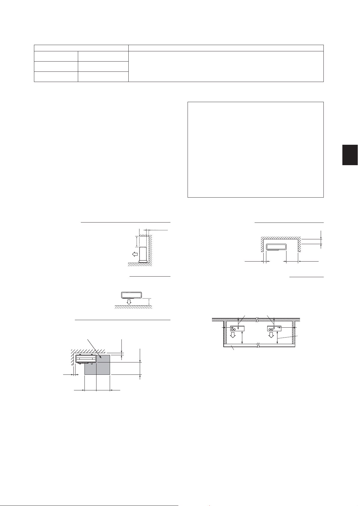
FREE SPACE REQUIRED AROUND OUTDOOR UNIT
Obstacles above
1.
When there is no obstacle in front
and on the sides of the unit, it is allowed to install the unit where an
obstacle is above the unit only if the
space shown in the figure is provided.
Obstacles in front (blowing) only
3.
When there is an obstacle in front of
the unit as shown in the figure, open
space above, behind, and on the
sides of the unit is required.
Service space
5.
Provide space for service and maintenance as shown in the figure.
Service space
100 or more
350 or more
500 or more
100 or more
350 or more
100 or more
500 or more
500 or more
Front (blowing) side open
2.
As long as space indicated
in the figure is provided, it
is allowed to install the unit
where obstacles are behind
and on the sides of the unit.
(No obstacle above the unit)
100 or more
Obstacles in front, behind and on side(s)
4.
• When installing the unit in an area that is enclosed with walls such
as a verandah, be sure to have enough space as shown below.
In this case, the air conditioning capacity and power consumption
might deteriorate.
• When installing two or more units, do not install the units in front or
behind each other.
200 or more
100 or more
500 or more
Height of the obstacle is 1200 or less
200 or more
350 or more
350 or more
500 or more
(Unit: mm)
En-2
Page 4
1-5. INSTALLATION DIAGRAM
More than
100 mm
Open as a rule
More than 500 mm if the back,
both sides and top are open
Open as a rule
More than 500 mm
if the front and both
sides are open
After the leak test, apply insulating material tightly so that there is
no gap.
When the piping is to be attached to a wall containing metals
(tin plated) or metal netting, use
a chemically treated wooden
piece 20 mm or thicker between
the wall and the piping or wrap 7
to 8 turns of insulation vinyl tape
around the piping.
To use existing piping, perform
COOL operation for 30 minutes
and pump down before removing
the old air conditioner. Remake
flare according to the dimension
for new refrigerant.
More than 100 mm
More than 200 mm if there are
obstacles to both sides
More than 350 mm
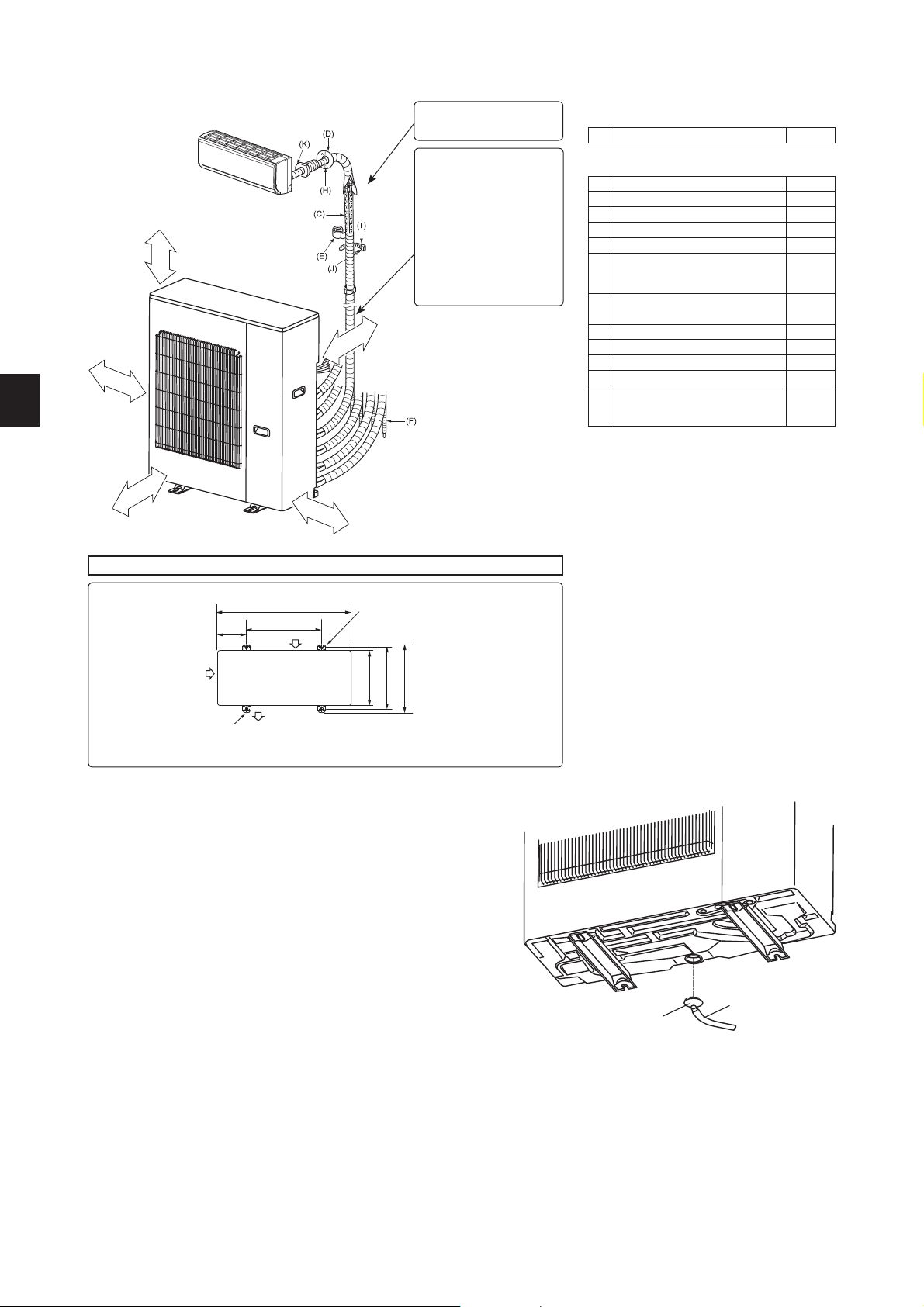
ACCESSORIES
Check the following parts before installation.
(1) Drain socket 1
PARTS TO BE PROVIDED AT YOUR SITE
(A) Power supply cord* 1
(B) Indoor/outdoor unit connecting wire* 1
(C) Extension pipe 1
(D) Wall hole cover 1
(E) Piping tape 1
Extension drain hose
(F)
(or soft PVC hose, 15 mm inner
1
diameter or hard PVC pipe VP16)
(G) Refrigeration oil
Little
amount
(H) Putty 1
(I) Pipe fixing band 2 to 7
(J) Fixing screw for (I) 2 to 7
(K) Wall hole sleeve 1
Soft PVC hose, 15 mm inner di-
(L)
ameter or hard PVC pipe VP16 for
1
drain socket (1)
* Note:
Place indoor/outdoor unit connecting wire (B) and
power supply cord (A) at least 1 m away from the
TV antenna wire.
The “Q’ty” for (B) to (K) in the above table is quan
tity to be used per indoor unit.
-
Units should be installed by licensed contractor according to local code requirements.
Outdoor unit installation
200
mm
Air inlet
2 - 12 mm × 36 mm
oval holes (Base bolt M10)
900 mm
500 mm
Air inlet
Air outlet
2-U-shape notched holes
(Base bolt M10)
320 mm
355 mm
387 mm
1-6. DRAIN PIPING FOR OUTDOOR UNIT
Please perform the drain piping work only when draining from one place.
1) Provide drain piping before indoor and outdoor piping connection.
2) Connect the soft PVC hose (L) I.D.15 mm as shown in the illustration.
3) Make sure to provide drain piping with a downhill grade for easy drain flow.
Note:
Install the unit horizontally.
Do not use the drain socket (1) in the cold regions. Drain may freeze and it makes
the fan stop.
The outdoor unit produces condensate during the heating operation. Select the in
stallation place to ensure to prevent the outdoor unit and/or the grounds from being
wet by drain water or damaged by frozen drain water.
-
(L) Soft PVC hose
(1) Drain socket
En-3
Page 5
2. OUTDOOR UNIT INSTALLATION
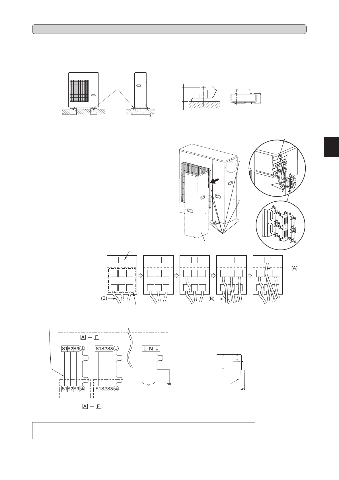
2-1. INSTALLING THE UNIT
• Be sure to fix the unit’s legs with bolts when installing it.
• Be sure to install the unit firmly to ensure that it does not fall by an earthquake or a gust.
• Refer to the figure in the right for concrete foundation.
• Do not use the drain socket and the drain caps in the cold region.
Drain may freeze and it makes the fan stop.
Fix here with
M10 bolts.
Make the setting
depth deeper.
Make with wider.
2-2. CONNECTING WIRES FOR OUTDOOR UNIT
1) Remove the service panel.
2) Loosen terminal screw, and connect indoor/outdoor unit connecting
wire (B) from the indoor unit correctly on the terminal block. Be careful
not to make mis-wiring. Fix the wire to the terminal block securely so
that no part of its core is appeared, and no external force is conveyed
to the connecting section of the terminal block.
3) Firmly tighten the terminal screws to prevent them from loosening. Af
ter tightening, pull the wires lightly to confirm that they do not move.
4) Perform 2) and 3) for each indoor unit.
5) Connect power supply cord (A).
6) Fix indoor/outdoor unit connecting wire (B) and power supply cord (A)
with the cable clamps.
7) Close the service panel securely. Make sure that 3-2. PIPE CONNEC
TION is completed.
• After making connections between both power supply cord (A) and
indoor/outdoor unit connecting wire (B), be sure to fix both cable and
wire with cable clamps.
Power supply
Connecting order
• Connect the terminal block in
following order.
A→B→C→D→E→F→P
P
DE
P
F
DE
Anchor leg
25 or less
Anchor both length
-
-
Screws
Service panel
P
F
E
F
D DEF
DEF
500
Anchor both pitch
P
(Unit: mm)
Clamps
355
Terminal block
for power supply
Cable clamps
P
ABC
Terminal block for
indoor/outdoor unit
Indoor/outdoor unit
connecting wire
Terminal block
Terminal block Terminal block
<INDOOR UNIT>
• Be sure to attach each screw to its correspondent terminal when securing the cord and/or the wire to the terminal block.
• Make earth wire a little longer than others. (More than 35 mm)
• For future servicing, give extra length to the connecting wires.
<OUTDOOR UNIT>
Terminal block
<INDOOR UNIT>
ABC
Terminal block for
power supply
POWER SUPPLY
~/N 230 V 50 Hz
ABC
ABC
15 mm
35 mm
Lead wire
ABC
En-4
Page 6

3. FLARING WORK AND PIPE CONNECTION
3-1. FLARING WORK
1) Cut the copper pipe correctly with pipe cutter. (Fig. 1, 2)
2) Completely remove all burrs from the cut cross section of pipe. (Fig. 3)
• Aim the copper pipe downward while removing burrs to prevent
burrs from dropping in the pipe.
3) Remove flare nuts attached to indoor and outdoor units, then put them
on pipe having completed burr removal. (Not possible to put them on
after flaring work.)
4) Flaring work (Fig. 4, 5). Firmly hold copper pipe in the dimension
shown in the table. Select A mm from the table according to the tool
selected.
5) Check
• Compare the flared work with Fig. 6.
• If flare is noted to be defective, cut off the flared section and do flar-
ing work again.
Burr
Copper pipe
Spare reamer
Pipe cutter
Copper
pipe
Good
No good
Tilted Uneven Burred
Fig. 1 Fig. 2
Flaring tool
Pipe diameter
(mm)
ø6.35 (1/4”) 17
ø9.52 (3/8”) 22 34.3 to 41.2 350 to 420
ø12.7 (1/2”) 26
ø15.88 (5/8”) 29 73.5 to 78.4 750 to 800
Nut
Clutch
(mm)
type tool
for R410A
0 to 0.5 1.0 to 1.5
Clutch
type tool
for R22
Wing nut
type tool
for R22
1.5 to 2.0
2.0 to 2.5
N•m kgf•cm
13.7 to 17.7 140 to 180
49.0 to 56.4 500 to 575
Die
Flare nut
3-2. PIPE CONNECTION
A (mm) Tightening torque
1) Apply a thin coat of refrigeration oil (G) to the flared ends of the pipes
and the pipe connections of the outdoor unit.
2) Align the center of the pipe with that of the pipe connections of the
outdoor unit, then hand tighten the flare nut 3 to 4 turns.
3) Tighten the flare nut with a torque wrench as specified in the table.
• Over-tightening may cause damage to the flare nut, resulting in re-
frigerant leakage.
• Be sure to wrap insulation around the piping. Direct contact with the
bare piping may result in burns or frostbite.
When installing the unit, securely
connect the refrigerant pipes before
starting the compressor.
WARNING
3-3. INSULATION AND TAPING
1) Cover piping joints with pipe cover.
2) For outdoor unit side, surely insulate every piping including valves.
3) Using piping tape (E), apply taping starting from the entry of outdoor
unit.
• Stop the end of piping tape (E) with tape (with adhesive agent at-
tached).
• When piping have to be arranged through above ceiling, closet or
When there are the ports which are
not used, make sure their nuts are
tightened securely.
CAUTION
where the temperature and humidity are high, wind additional commercially sold insulation to prevent condensation.
4. PURGING PROCEDURES, LEAK TEST, AND TEST RUN
Clutch type
Fig. 3 Fig. 4
Smooth all
around
Copper pipe
Fig. 5 Fig. 6
Wing nut type
Inside is shining without any
scratches.
Even length
all around
4-1. PURGING PROCEDURES AND LEAK TEST
1) Remove service port cap of stop valve on the side of the outdoor unit
gas pipe. (The stop valves are fully closed and covered in caps in their
initial state.)
2) Connect gauge manifold valve and vacuum pump to service port of
stop valve on the gas pipe side of the outdoor unit.
3) Run the vacuum pump. (Vacuumize for more than 15 minutes.)
4) Check the vacuum with gauge manifold valve, then close gauge mani
fold valve, and stop the vacuum pump.
5) Leave as it is for one or two minutes. Make sure the pointer of gauge
manifold valve remains in the same position. Confirm that pressure
gauge shows -0.101 MPa [Gauge] (-760 mmHg).
6) Remove gauge manifold valve quickly from service port of stop valve.
7) Fully open all stop valves on the gas pipe and the liquid pipe. Operat
ing without fully opening lowers the performance and this causes trouble.
8) Refer to 1-2., and charge the prescribed amount of refrigerant if
needed. Be sure to charge slowly with liquid refrigerant. Otherwise,
composition of the refrigerant in the system may be changed and af
fect performance of the air conditioner.
9) Tighten cap of service port to obtain the initial status.
10
) Leak test
-
-
-
Compound pressure
-0.101MPa
(-760 mmHg)
Handle Low
Gauge manifold
valve
(for R410A)
Cap
Pull the handle toward you
and rotate 1/4 turn in a counter
clockwise direction to open.
gauge (for R410A)
Close
Pressure gauge
(for R410A)
Handle High
Charge hose
(for R410A)
Vacuum pump
(for R410A)
*4 to 5 turns
*Open
Hexagonal
wrench
Stop valve cap
(Torque 19.6 to
Service port cap
(Torque 13.7 to
17.7 N•m, 140 to
180 kgf•cm)
29.4 N•m, 200
to 300 kgf•cm)
Open
Push in the handle and rotate the
cap back to its original position.
*Close
En-5
Page 7

4-2. GAS CHARGE
Perform gas charge to unit.
1) Connect gas cylinder to the service port of stop valve.
2) Perform air purge of the pipe (or hose) coming from refrigerant gas cylinder.
3) Replenish specified amount of the refrigerant, while operating the air conditioner for cooling.
Note:
In case of adding refrigerant, comply with the quantity specified for the refrigerating cycle.
CAUTION:
When charging the refrigerant system with additional refrigerant, be sure to use
liquid refrigerant. Adding gas refrigerant may change the composition of the
Union
Union
Union
Union
Refrigerant gas
cylinder
operating valve
(for R410A)
Stop valve
Indoor
unit
Stop valve with
service port
Gauge manifold
valve (for R410A)
refrigerant in the system and affect normal operation of the air conditioner. Also,
charge the liquid refrigerant slowly, otherwise the compressor will be locked.
To maintain the high pressure of the gas cylinder, warm the gas cylinder with
warm water (under 40°C) during cold season. But never use naked fire or steam.
Refrigerant gas cylinder for R410A with siphon
Refrigerant (liquid)
Electronic scale for refrigerant charging
4-3. LOCKING THE OPERATION MODE OF THE AIR CONDITIONER (COOL, DRY, HEAT)
• Description of the function:
With this function, once the operation mode is locked to either COOL/DRY
mode or HEAT mode, the air conditioner operates in that mode only.
* Changing the setting is required to activate this function. Please explain about
this function to your customers and ask them whether they want to use it.
[How to lock the operation mode]
1) Be sure to turn off the main power for the air conditioner before making the
setting.
2) Set the “1” of SW1 on the outdoor controller board to ON to enable this function.
3) To lock the operation mode in COOL/DRY mode, set the “2” of SW1 on the
outdoor controller board to OFF. To lock the operation in HEAT mode, set the
same switch to ON.
4) Turn on the main power for the air conditioner.
Liquid
pipe
Gas
pipe
Outdoor
unit
Charge hose
(for R410A)
COOL/DRY
HEAT
4-4. LOWERING THE OPERATION NOISE OF THE OUTDOOR UNIT
• Description of the function:
With this function, the operating noise of the outdoor unit can be lowered by reducing the operation load, for example, during nighttime in COOL mode.
However, please note that the cooling and heating capacity may lower if this function is activated.
* Changing the setting is required to activate this function. Please explain about this function to your customers and ask them whether they want to use it.
[How to lower the operating noise]
1) Be sure to turn off the main power for the air conditioner before making the
setting.
2) Set the “3” of SW1 on the outdoor controller board to ON to enable this function.
Lower the operating noise
3) Turn on the main power for the air conditioner.
4-5. CHANGING THE AMPERE LIMIT
• Description of the function:
With this function, the amount of current that flows in the outdoor unit can be
changed.
Note:
Use this function only when the amount of current exceeds the allowed value.
[How to change the ampere limit]
1) Be sure to turn off the main power for the air conditioner before making the
setting.
2) Make the setting referring to the table below.
3) Turn on the main power for the air conditioner.
SW2
20A
25A
Factory setting
Full
En-6
Page 8

4-6. TEST RUN
• Test runs of the indoor units should be performed individually. See the installation manual coming with the indoor unit, and make sure all the units operate properly.
• If the test run with all the units is performed at once, possible erroneous connections of the refrigerant pipes and the indoor/outdoor unit connecting wires
cannot be detected. Thus, be sure to perform the test run one by one.
About the restart protective mechanism
Once the compressor stops, the restart preventive device operates so the compressor will not operate for 3 minutes to protect the air conditioner.
Wiring/piping correction function
This unit has a wiring/piping correction function which corrects wiring and piping combination. When there is possibility of incorrect wiring and piping combination, and confirming the combination is difficult, use this function to detect and correct the combination by following the procedures below.
Make sure that the following is done.
• Power is supplied to the unit.
• Stop valves are open.
Note:
During detection, the operation of the indoor unit is controlled by the outdoor unit. During detection, the indoor unit automatically stops operation. This is not
a malfunction.
Procedure
Press the piping/wiring correction switch (SW871) 1 minute or more after turning on the
power supply.
• Correction completes in 10 to 20 minutes. When the correction is completed, its result
is shown by LED indication. Details are described in the following table.
• To cancel this function during its operation, press the piping/wiring correction switch
(SW871) again.
• When the correction completed without error, do not press the piping/wiring correction
switch (SW871) again.
When the result was “cannot be corrected”, press the piping/wiring correction switch
(SW871) again to cancel this function. Then, confirm the wiring and piping combination
in a conventional manner by operating the indoor units one by one.
• The operation is done while the power is supplied. Make sure not to contact parts
other than the switch, including the P.C. board. This may cause electric shock or burn
by hot parts and live parts around the switch. Contacting the live parts may cause P.C.
board damage.
• To prevent electronic control P.C. board damage, make sure to perform static elimi
nation before operating this function.
• This function does not operate when the outside temperature is 0°C or below.
LED indication during detection:
1 (Red) 2 (Yellow) 3 (Green)
Lighted Lighted Blinking
Result of piping/wiring correction function
1 (Red) 2 (Yellow) 3 (Green)
Lighted Not lighted Lighted
Blinking Blinking Blinking Cannot be corrected
-
LED
LED
Other indications
Completed
(Corrected successfully)
Refer to “SAFETY PRECAUTIONS WHEN LED
FLASHES” located behind
the service panel.
Result
4-7. EXPLANATION TO THE USER
• Using the OPERATING INSTRUCTIONS, explain to the user how to use the air conditioner (how to use the remote controller, how to remove the air filters, how to remove or put the remote controller in the remote controller holder, how to clean, precautions for operation, etc.).
• Recommend the user to read the OPERATING INSTRUCTIONS carefully.
5. RELOCATION AND MAINTENANCE
5-1. PUMPING DOWN
When relocating or disposing of the air conditioner, pump down the system following the procedure below so that no refrigerant is released into the atmosphere.
1) Connect the gauge manifold valve to the service port of the stop valve on the gas pipe side of the outdoor unit.
2) Fully close the stop valve on the liquid pipe side of the outdoor unit.
3) Close the stop valve on the gas pipe side of the outdoor unit almost completely so that it can be easily closed fully when the pressure gauge shows 0
MPa [Gauge] (0 kgf/cm
4) Start the emergency COOL operation on all the indoor units.
To start the emergency operation in COOL mode, disconnect the power supply plug and/or turn off the breaker. After 15 seconds, connect the power
supply plug and/or turn on the breaker, and then press the E.O. SW once. (The emergency COOL operation can be performed continuously for up to 30
minutes.)
5) Fully close the stop valve on the gas pipe side of the outdoor unit when the pressure gauge shows 0.05 to 0 MPa [Gauge] (approx. 0.5 to 0 kgf/cm
6) Stop the emergency COOL operation.
Press the E.O. SW several times until all LED lamps turn off. Refer to operating instructions for details .
When pumping down the refrigerant, stop the compressor before disconnecting
the refrigerant pipes. The compressor may burst if air etc. get into it.
2
).
2
).
WARNING
En-7
Page 9

СОДЕРЖАНИЕ
1. ПРЕЖДЕ ЧЕМ ПРОИЗВОДИТЬ УСТАНОВКУ ................................................. 1
2. УСТАНОВКА НАРУЖНОГО ПРИБОРА............................................................. 4
3. РАБОТЫ ПО ЗАДЕЛКЕ ТРУБ И СОЕДИНЕНИЕ ТРУБ ................................... 5
ПРОЦЕДУРЫ ПРОДУВКИ, ПРОВЕРКА НА ОТСУТСТВИЕ УТЕЧЕК И ТЕСТОВЫЙ ПРОГОН
4.
РУССКИЙ
5. ПЕРЕМЕЩЕНИЕ И ОБСЛУЖИВАНИЕ .............................................................7
... 5
Инструменты, необходимые для установки
Крестообразная отвертка
Уровень
Линейка
Универсальный нож или ножницы
Тарированный ключ
Гаечный ключ
Шестигранный гаечный ключ 4 мм
Кон
усный инструмент для
R410A
Коллектор с измерителем для
R410A
Вакуумный насос для R410A
Заправочный шланг для R410A
Труборе
з с разверткой
1. ПРЕЖДЕ ЧЕМ ПРОИЗВОДИТЬ УСТАНОВКУ
1-1.
В ЦЕЛЯХ ОБЕСПЕЧЕНИЯ БЕЗОПАСНОСТИ ВСЕГДА СОБЛЮДАЙТЕ СЛЕДУЮЩИЕ ПОЛОЖЕНИЯ
• Перед установкой кондиционера обязательно прочитайте раздел “В ЦЕЛЯХ ОБЕСПЕЧЕНИЯ БЕЗОПАСНОСТИ ВСЕГДА СОБЛЮДАЙТЕ СЛЕ-
ДУЮЩИЕ ПОЛОЖЕНИЯ”.
• Обязательно соблюдайте меры предосторожности, изложенные ниже - в них содержатся важные с точки зрения безопасности положения.
• Прочитав данное руководство, храните его вместе с ИНСТРУКЦИЕЙ ПО ЭКСПЛУАТАЦИИ на случай возникновения вопросов.
• Оборудование соответствует IEC/EN 61000-3-12.
ПРЕДУПРЕЖДЕНИЕ
N Самостоятельная установка данного прибора (пользователем) запре-
щается.
Не завершение установки может вызвать пожар, поражение электрическим током,
травмы вследствие падения прибора или утечку воды. Обратитесь к дилеру, у
которого вы приобрели данный прибор или к квалифицированному специалисту
по установке.
N Выполняйте установку с соблюдением правил безопасности, используя
“Руководство по установке” в качестве справочника.
Не завершение установки может вызвать пожар, поражение электрическим
током, травмы вследствие падения прибора или утечку воды.
N При установке прибора используйте соответствующие защитное обо-
рудование и инструменты в целях безопасности.
Невыполнение этого требования может привести к травме.
N Надежно устанавливайте прибор на основе, которая может выдержать
его вес.
Если основа не выдержит вес прибора, он может упасть и нанести увечья.
N Выполняйте электромонтажные работы в соответствии с “Руководс-
твом по установке” и обязательно используйте отдельный контур питания. Не подключайте другие электрические приборы к одной розетке
с прибором.
При недостаточной мощности контура питания или в случае незавершенных
электромонтажных работ возможен пожар или поражение электрическим
током.
N Не повредите провода при чрезмерном их сжатии компонентами или
винтами.
Поврежденные провода могут привести к возникновению пожара.
N Обязательно отсоедините прибор от источника электропитания при
проведении настройки печатной платы электронного управления внутреннего прибора или при работе с электропроводкой.
Невыполнение данного требования может привести к поражению электри-
ческим током.
N Используйте провода указанных параметров для надежного соедине-
ния внутреннего и наружного приборов. Надежно закрепите провода в
секторах соединений клеммной колодки, чтобы натяжение провода не
передавалось в секторы соединений.
Не завершение подключения и изоляции может привести к возгоранию.
N Не устанавливайте прибор в помещении, где возможна утечка легко-
возгораемого газа.
При утечке и скоплении газа в непосредственной близости от прибора,
возможен взрыв.
N Не используйте промежуточные соединения в шнуре питания или
удлинитель шнура питания, и не подсоединяйте несколько приборов к
одной розетке переменного тока.
Это может привести к пожару или поражению электрическим током вследс-
твие дефекта контакта, дефекта изоляции, превышения допустимого тока в
сети и т.д.
N При выполнении работ по установке обязательно используйте детали,
входящие в комплект поставки, или детали, характеристики которых
приводятся в данном руководстве.
Использование дефектных деталей может привести к травме или утечке
воды вследствие пожара, поражения электрическим током, падения прибора
и т.д.
N При подключении шнура питания к розетке, убедитесь, что на нем и на
розетке отсутствует пыль, мусор и незакрепленные детали. Убедитесь,
что вилка вставлена в розетку до упора.
ОСТОРОЖНО
N Устанавливайте прерыватель утечки тока на землю, в зависимости от
места установки.
Если прерыватель утечки тока на землю не установлен, возможно поражение
электрическим током.
N
Надежно выполняйте соединения дренажных труб/трубных соединений в
соответствии с требованиями “Руководства по установке”.
В случае дефекта соединений дренажных труб/трубных соединений возможно капание
воды из прибора и повреждение имущества в помещении вследствие намокани
(Неправильное выполнение данной инструкции в определенных условиях может привести к тяжелой травме.)
1-2. ХАРАКТЕРИСТИКИ
Питание *1
Модель
MXZ-6C120VA 230 V 50 Hz 32 A
Подсоедините к выключателю питания с зазором не менее 3 мм в разомкнутом
*1
положении для прерывания фазы источника питания. (В разомкнутом положении выключатель питания должен отсоединять все фазы.)
*2 Используйте провода, соответствующие конструкции 60245 IEC 57. Используйте
соединительный провод для помещений/улицы, соответствующий техническим
характеристикам проводов, указанным в руководстве по установке внутреннего
блока.
*3 Никогда не используйте трубы, с толщиной, меньше указанной. Сопротивление
давления будет недостаточным.
*4 Используйте медную трубу или бесшовную трубу из сплава меди.
*5 Будьте осторожны при сгибании трубы, во избежание ее повреждения.
Номи-
нальное
напряжение
(Невыполнение данного требования может привести к смертельному исходу, тяжелой травме и т.д.)
В случае, если на вилке или розетке присутствует пыль, мусор или незакреп
ленные части, это может привести к возгоранию или поражению электрическим током. При обнаружении незакрепленных частей на вилке, замените
ее.
N Надежно прикрепите электрокрышку к внутреннему прибору, а сервисную
панель – к наружному прибору.
Если электрокрышка и сервисная панель ненадежно прикреплены соответс-
твенно к внутреннему и наружному приборам, это может привести к пожару
или поражению электрическим током вследствие попадания пыли, воды и
т.д. внутрь приборов.
N При установке, перемещении или техобслуживании прибора следите
за тем, чтобы в охлаждающий контур не попало другое вещество, за
исключением указанного хладагента (R410A).
Присутствие какого-либо инородного вещества, например, воздуха, может привести
к аномальному повышению давления, следствием которого может стать взрыв или
травма. Использование любого иного хладагента, кроме указанного для системы,
приведет к механическому отказу, неисправности системы или поломке прибора.
В худшем случае это может привести к серьезному препятствию для обеспечения
безопасности изделия.
N Запрещается выпускать хладагент в атмосферу. В случае утечки хла-
дагента при установке, проветрите помещение.
Если хладагент вступит в контакт с пламенем, возможно генерирование
вредного газа. Утечка хладагента может стать причиной удушья. Обеспечьте
вентиляцию в соответствии с EN378-1.
N Убедитесь в отсутствии утечки газа хладагента после завершения
установки.
В случае утечки газа хладагента внутри помещения и его последующего
контакта с огнем тепловентилятора, отопителя помещений, печи и т.д. про
исходит образование вредных для здоровья веществ.
N При установке используйте подходящие инструменты и соединитель-
ные материалы.
Давление R410A в 1,6 раза выше, чем R22. Использование не подходящих
материалов и не завершение установки может привести к разрыву труб и
нанесению увечий.
N При сливании хладагента, останавливайте компрессор до отключения
труб с хладагентом.
Если трубы с хладагентом отсоединить при работающем компрессоре и открытом
стопорном клапане, возможно засасывание воздуха и чрезмерное повышение
давления в контуре охлаждения. Это может привести к разрыву труб или нанесению
увечий.
N При установке прибора, надежно подсоедините трубы с хладагентом
до запуска компрессора.
Если компрессор запускается до подсоединения труб с хладагентом и при открытом
стопорном клапане, возможно засасывание воздуха и чрезмерное повышение давления в контуре охлаждения. Это может привести к разрыву труб или нанесению
увечий.
N Затягивайте конусную гайку с помощью тарированного ключа с крутя-
щим моментом, указанным в данном руководстве.
Слишком сильная затяжка конусной гайки может привести к поломке гайки
через некоторое время, результатом чего станет утечка хладагента.
N Прибор необходимо устанавливать в соответствии с национальными
нормами в сфере электропроводки.
N Заземлите прибор надлежащим образом.
Запрещается подсоединять заземление к газовым и водопроводным трубам,
молниеотводу или проводу заземления телефонной сети. Дефект заземления
может привести к поражению электрическим током.
N Не дотрагивайтесь до воздухозаборника и алюминиевых ребер вне-
шнего устройства.
Это может нанести увечья.
N Не устанавливайте внешний прибор в местах обитания мелких живот-
ных.
Мелкие животные могут проникнуть внутрь прибора и дотронуться до внут-
ренних электрических частей, приведя к неисправности, выделению дыма
или возгоранию. Кроме того, порекомендуйте пользователем поддерживать
я.
территорию вокруг прибора в чистоте.
Часто-
та
Емкость
прерыва-
теля
Характеристики проводов *2
Питание
3-жильный
4,0 мм
Внешняя/внутренняя комму-
2
тация
4-жильный
1,0 / 1,5 мм
Макс. длина трубы
для внутреннего
мультисистемной
2
Пропорции длины и высоты тру
Макс. количество
прибора / для
модели
Макс.
разность высо *9
изгибов для внут-
реннего прибора /
для мультисистем-
ной модели
25 м / 80 м 15 м 25 / 80 20 г/м
*6 Радиус изгиба трубы с хладагентом должен быть не менее 100 мм.
*7 Изоляционный материал: Жаростойкий пенопласт с зернистостью 0,045
*8 Используйте изоляцию указанной толщины. Чрезмерная толщина изоляции мо
жет привести к неправильной установке внутреннего прибора, а недостаточная
толщина может вызвать капание влаги.
*9 Если наружный прибор устанавливается выше внутреннего прибора, макс. раз
ница высот сокращается до 10 м.
*10
Если длина трубы превышает 60 м, необходима заправка дополнительным
хладагентом (R410A). (Если длина труб не превышает 60 м, заправка дополнительного хладагента не требуется.)
Дополнительный хладагент = A × (длина трубы (м)
*3, *4, *5, *6, *7, *8
Настройка хлада-
гента A *10
–
60)
-
-
-
-
Ru-1
Page 10

1-3. ВЫБОР ДОПОЛНИТЕЛЬНЫХ СТЫКОВ ДЛЯ РАЗНЫХ ДИАМЕТРОВ
Если диаметр соединительных труб не совпадает с размером отверстия наружного прибора, используйте дополнительные стыки для разных диаметров согласно следующей таблице.
(Единица измерения: мм (дюйм))
Размер отверстия наружного прибора
MXZ-6C Жидкость / Газ
ПРИБОР A 6,35 (1/4) / 12,7 (1/2)
ПРИБОР B - F 6,35 (1/4) / 9,52 (3/8)
(размер отверстия наружного прибора → диаметр соединительной трубы)
Информацию о диаметре соединительной трубы внутреннего прибора можно найти в руководстве
Дополнительные стыки для разных диаметров
→
6,35 (1/4)
9,52 (3/8) → 12,7 (1/2) : MAC-454JP
9,52 (3/8) → 15,88 (5/8) : PAC-SG76RJ
12,7 (1/2) → 9,52 (3/8) : MAC-A455JP
12,7 (1/2) → 15,88 (5/8) : MAC-A456JP
по установке для монтажа внутреннего прибора.
9,52 (3/8) : PAC-493PI
1-4. ВЫБОР МЕСТА УСТАНОВКИ
• Где он не подвержен воздействию сильных ветров.
• Где нет преград на пути воздушного потока и нет пыли.
• В месте, которое подвергается наименьшему воздействию дождя
и прямого солнечного света.
• Где работа прибора или горячий воздух не мешают соседям.
• Где есть прочная стена или опорная конструкция – это предотвра
тит повышение уровня рабочего шума или вибрации.
• Где нет риска утечки горючих газов.
• При установке прибора убедитесь в надежности крепления ножек
прибора.
• Где прибор будет расположен на расстоянии не менее 3 м от антенны телевизора или радиоприемника. В регионах со слабыми
радиоволнами при работе кондиционера возникают помехи при
приеме теле- и радиовещания. Для нормального приема теле- и
радиовещания может потребоваться усилитель.
• Устанавливайте прибор строго горизонтально.
• Производите установку в местах, где отсутствует воздействие
снегопада, ветра и снега. В районах с сильным снегопадом уста
новите навес, опору и/или несколько отражательных перегородок.
Примечание:
Рекомендуется сделать трубную петлю рядом с наружным прибором
для уменьшения передаваемой оттуда вибрации.
-
-
Примечание:
При эксплуатации кондиционера при низкой температуре наружного воздуха обязательно следуйте приведенным ниже инструкциям.
• Запрещается устанавливать наружный прибор в местах, где
воздухозаборное/воздуховыпускное отверстие могут находиться под непосредственным воздействием ветра.
• Во избежание воздействия ветра наружный прибор необходимо
устанавливать так, чтобы его воздухозаборное отверстие было
обращено к стене.
• Во избежание воздействия ветра со стороны воздуховыпуск
ного отверстия наружного прибора рекомендуется установить
отражательную перегородку.
При выборе места установки избегайте следующих мест, в которых
возможно появление неисправностей в работе кондиционера.
• В местах, где возможна утечка воспламеняющегося газа.
• В местах, где много машинного масла.
• В местах, где много соли, например, на морском побережье.
• В местах образования сероводородного газа, например, рядом
с горячим природным источником.
• В местах с наличием высокочастотного или беспроводного обо
рудования.
• Где существуют значительные выбросы летучих органических
соединений, включая соединения фталата, формальдегид и т.
д., которые могут вызвать химическое разложение.
НЕОБХОДИМО СВОБОДНОЕ ПРОСТРАНСТВО ВОКРУГ НАРУЖНОГО ПРИБОРА
Препятствия выше
1.
Если спереди и с боковых сторон
блока пространство свободно, при
установке допускается наличие
препятствий над блоком в случае,
если выдерживаются расстояния,
показанные на рисунке.
100 или более
500 или более
Передняя (выдувающая) часть открыта
2.
Если выдерживаются расстояния, показанные на
рисунке, при установке допускается наличие препятствий позади и с боковых
сторон блока. (Над блоком
нет препятствий)
200 или более
-
-
Ru-2
Препятствия только спереди (обдув)
3.
Если спереди блока имеется препятствие, как показано на рисунке,
то над блоком, позади и с боковых
сторон блока нужно обеспечить
свободное пространство.
Место для обслуживания
5.
Нужно обеспечить пространство для ремонта и обслуживания,
как показано на рисунке.
Место для обслуживания
100 или
более
500 или более
100 или более
350 или более350 или более
500 или
более
100 или более
Препятствия спереди, позади и с боковых сторон
4.
• При установке прибора на участок, закрытый со всех сторон,
например, на веранду, обязательно оставьте свободным достаточное пространство, как показано ниже.
В противном случае может ухудшиться эффективность конди-
ционирования и возрасти энергопотребление.
• При установке двух или более приборов не устанавливайте их
друг за другом или напротив друг друга.
200 или более
100 или более
500 или
более
Высота препятствия 1200 или меньше
(Единица измерения: мм)
350 или более
350 или более
500 или более
Page 11

1-5. МОНТАЖНАЯ СХЕМА
После проверки на отсутствие
утечек плотно нанесите изоляционный материал, чтобы
обеспечить отсутствие зазоров.
В случае крепления трубопроводов к стене, содержащей металлы (обшитые белой жестью)
или металлическую сетку, уста
новите химически обработанную
деревянную пластину толщиной
не менее 20 мм между стеной
Как правило открыто
Более
100 мм
Как правило открыто
Более 500 мм, если задняя,
обе боковые и верхняя части
открыты
Более 500 мм, если пе
редняя и обе боковые
части открыты
-
Более 100 мм
Более 200 мм при наличии
препятствий для обеих сторон
Более 350 мм
Установка должна выполняться лицензированным подрядчиком в соответствии с требованиями местных нормативных актов.
и трубами, или оберните трубы
виниловой изолентой 7 - 8 раз.
Для использования имеющегося
трубопровода выполните опе
рацию COOL (ОХЛАЖДЕНИЕ) в
течение 30 минут и осуществите
откачку перед демонтажем старо
го кондиционера. Повторно смонтируйте раструб в соответствии с
размером для нового количества
хладагента.
ДОПОЛНИТЕЛЬНЫЕ ПРИНАДЛЕЖНОСТИ
Перед установкой проверьте наличие следующих деталей.
(1) Дренажный разъем 1
ДЕТАЛИ, КОТОРЫЕ НЕОБХОДИМО ПРИОБРЕСТИ НА МЕСТЕ
-
(A) Шнур электропитания* 1
Провод соединения внутреннего/
(B)
наружного приборов*
(C) Удлинительная труба 1
(D) Крышка для стенного отверстия 1
-
(E) Лента для труб 1
-
Удлинительный дренажный
шланг
(F)
(или мягкий шланг из ПВХ с внут-
ренним диаметром 15 мм или
твердая труба из ПВХ VP16)
(G) Охлаждающее масло
(H) Замазка 1
(I) Лента для фиксирования труб 2 - 7
(J) Шуруп крепления для (I) 2 - 7
(K) Втулка для стенного отверстия 1
Мягкий шланг из ПВХ с внутренним диаметром 15 мм или
(L)
твердая труба из ПВХ VP16 для
дренажного разъема (1)
* Примечание:
Разместите провод соединения внутреннего/наружного приборов (B) и шнур электропитания
(A) на расстоянии как минимум 1 м от провода
телевизионной антенны.
“Количество” (B) для (K) в вышеуказанной табли
це является количеством, которое необходимо
использовать для каждого внутреннего прибора.
1
1
Небольшое
количество
1
-
Установка наружного прибора
2-U-образные отверстия с пазом
(Болт основания M10)
320 мм
355 мм
387 мм
Воздухозаборное
отверстие
2 - 12 мм × 36 мм
овальные отверстия
(Болт основания M10)
200
мм
Воздухозаборное
отверстие
900 мм
500 мм
Воздуховыпускное
отверстие
1-6. ТРУБОПРОВОДЫ ДРЕНАЖНОЙ СИСТЕМЫ НАРУЖНОГО БЛОКА
Выполняйте работы на дренажных трубах только при дренаже с одного места.
1) Выполните прокладку трубопроводов дренажной системы перед соединением трубопроводов внутреннего и наружного приборов.
2) Подключите мягкий шланг из ПВХ (L) диаметром 15 мм как показано на рисунке.
3) Обязательно проложите трубопроводы дренажной системы с наклоном
вниз по направлению слива.
Примечание:
Устанавливайте прибор строго горизонтально.
Не используйте дренажный разъем (1) в регионах с холодным климатом. Дренаж может замерзнуть, что приведет к останову вентилятора.
В режиме обогрева наружный блок вырабатывает конденсат. Выберите такое место установки, чтобы на наружный блок и/или основание не попадала
дренажная вода и так, чтобы избежать повреждений, которые может вызвать
замерзшая дренажная вода.
(1) Дренажный разъем
(L) Мягкий шланг из
ПВХ
Ru-3
Page 12

2. УСТАНОВКА НАРУЖНОГО ПРИБОРА
2-1. УСТАНОВКА ПРИБОРА
• Обязательно закрепите опоры прибора болтами при установке.
• Надежно устанавливайте прибор для предотвращения его падения при землетрясении или резких порывах ветра.
• См. рисунок справа для получения информации по установке на бетонном фундаменте.
• Не используйте дренажный разъем и дренажные колпачки в регионе с холодным климатом.
Дренаж может замерзнуть, что приведет к останову вентилятора.
Закрепите в
этом месте
болтами M10.
Сделайте глу
бину установки
больше.
-
Сделайте ширину
больше.
25 или меньше
Длина обоих анкеров
2-2.СОЕДИНИТЕЛЬНЫЕ ПРОВОДА НАРУЖНОГО ПРИБОРА
1) Снимите сервисную панель.
2) Ослабьте винт клеммной колодки и подсоедините соответству-
ющим образом провод соединения внутреннего/наружного приборов (В) от внутреннего прибора к клеммной колодке. Следите
за правильностью подсоединения проводов. Плотно прикрепите
провод к клеммной колодке, следя за тем, чтобы сердечник провода не был виден, и чтобы к соединительной секции клеммной
колодки не прилагалось внешнего усилия.
3) Плотно затягивайте винты клеммной колодки для предотвраще-
ния их ослабления. После затяжки винтов слегка потяните за провода, чтобы убедиться в их неподвижности.
4) Выполните 2) и 3) для каждого внутреннего прибора.
5) Подсоедините шнур электропитания (А).
6) Закрепите провод соединения внутреннего/наружного приборов
(В) и шнур электропитания (А) с помощью проводных зажимов.
7) Надежно закройте сервисную панель. Убедитесь, что этап 3-2.
СОЕДИНЕНИЕ ТРУБ завершен.
• После подключения шнура электропитания (A) и провода со
единения внутреннего/наружного приборов (В) убедитесь, что и
провод, и шнур закреплены с помощью проводных зажимов.
Электропитание
Порядок соединения
• Подключите клеммную колодку в следующем порядке.
A→B→C→D→E→F→P
P
DE
F
P
DE
-
Сервисная панель
F
D DEF
Анкерная
опора
Винты
P
E
F
DEF
500
Шаг обоих анкеров
(Единица измерения: мм)
Зажимы
P
355
Клеммная колодка
для электропитания
Проводные зажимы
P
Ru-4
ABC
Клеммная колодка для внутреннего/
наружного прибора
Провод соединения внутреннего/
наружного приборов
Клеммная колодка Клеммная колодка
Клеммная
колодка
<ВНУТРЕННИЙ ПРИБОР>
• Обязательно присоедините каждый винт к соответствующей клемме при фиксации шнура и/или провода к клеммному блоку.
• Провод заземления должен быть немного длиннее других. (Длиннее примерно на 35 мм)
• Для облегчения проведения техобслуживания в будущем оставьте припуск длины соединительных проводов.
<НАРУЖНЫЙ ПРИБОР>
Клеммная
колодка
<ВНУТРЕННИЙ ПРИБОР>
ABC
Клеммная
колодка для
электропитания
ЭЛЕКТРОПИТАНИЕ
~/N 230 В 50 Гц
ABC
ABC
15 мм
35 мм
Силовой провод
ABC
Page 13

3. РАБОТЫ ПО ЗАДЕЛКЕ ТРУБ И СОЕДИНЕНИЕ ТРУБ
3-1. РАЗВАЛЬЦОВКА
1) Правильно режьте медную трубу с помощью трубореза. (Рис. 1, 2)
2) Полностью удалите заусенцы с разрезанного поперечного сечения трубы. (Рис. 3)
• При удалении заусенцев наклоните медную трубку вниз, чтобы уда-
ленные заусенцы не попали внутрь трубки.
3) Снимите конусные гайки, прикрепленные к внутреннему и наружному
приборам, затем насадите их на трубу после полного удаления заусенцев. (После развальцовки насадка гаек невозможна.)
4) Развальцовка (Рис. 4, 5). Полностью соблюдайте размеры медной трубы, указанные в таблице. Выберите A мм из таблицы в соответствии с
используемым инструментом.
5) Проверьте
• Сравните развальцовку с Рис. 6.
• При обнаружении дефекта на развальцовке обрежьте развальцован-
ный участок и выполните развальцовку снова.
A (мм)
Диаметр
трубы (мм)
ø6,35 (1/4”) 17
ø9,52 (3/8”) 22 34,3 - 41,2 350 - 420
ø12,7 (1/2”) 26
ø15,88 (5/8”) 29 73,5 - 78,4 750 - 800
Гайка
(мм)
Инструмент
зажимного
типа для
R410A
Инструмент
зажимного
типа для R22
0 - 0,5 1,0 - 1,5
Инструмент
барашковой
гайки для R22
1,5 - 2,0
2,0 - 2,5
Крутящий момент затяжки
Н•м кгс•см
13,7 - 17,7 140 -180
49,0 - 56,4 500 - 575
3-2. СОЕДИНЕНИЕ ТРУБ
1) Нанесите тонкий слой холодильного масла (G) на раструбные концы руб
и трубные соединения наружного блока.
2) Выровняйте центр трубы, подсоединяемой к трубному соединению наружного блока, а затем затяните от руки раструбную гайку на 3-4 оборота.
3) Затяните раструбную гайку динамометрическим ключом, соблюдая крутящий момент, указанный в таблице.
• При превышении крутящего момента раструбная гайка может быть
повреждена, что приведет к утечке хладагента.
• Обязательно оберните трубы изоляционной обмоткой. Непосредствен
ный контакт с неизолированным трубопроводом может привести к ожогам или обморожению.
Заусенец
Обжимка
При установке прибора, надежно
подсоедините трубы с хладагентом до запуска компрессора.
-
Медная труба
Конусная гайка
ПРЕДУПРЕЖДЕНИЕ
Медная
труба
Рис. 1 Рис. 2
Дополнительная развертка
Труборез
Рис. 3 Рис. 4
Ровный край по
всему диаметру
Медная труба
Рис. 5 Рис. 6
Правильно Неправильно
Наклон
Неровность
Заусенцы
Развальцовочный инструмент
Тип муфты
Тип барашковой гайки
Блестящая
внутренняя
поверхность
безцарапин.
Одинаковая
длина по всему
диаметру
3-3. ИЗОЛЯЦИЯ И ОБМОТКА ЛЕНТОЙ
1) Оберните трубные стыки изоляцией для труб.
Со стороны наружного прибора обязательно оберните все трубы, включая клапаны.
2)
3) Используя ленту для труб (E), оберните трубы, начиная со входа наружного прибора.
• Зафиксируйте конец ленты для труб (E) лентой (с нанесенным на нее
клеящим составом).
•
При прокладке труб над потолком, в стенных шкафах или в местах с высо-
Если некоторые порты не используются, убедитесь, что их гайки
надежно затянуты.
ОСТОРОЖНО
кой температурой или влажностью, оберните их дополнительной изоляцией, имеющейся в продаже, для предотвращения образования конденсации.
4. ПРОЦЕДУРЫ ПРОДУВКИ, ПРОВЕРКА НА ОТСУТСТВИЕ УТЕЧЕК И ТЕСТОВЫЙ ПРОГОН
4-1. ПРОЦЕДУРЫ ПРОДУВКИ И ПРОВЕРКА НА ОТСУТСТВИЕ УТЕЧЕК
1) Снимите колпачок сервисного порта на стопорном клапане со
стороны трубы для газа наружного прибора. (В изначальном виде
запорные клапаны полностью закрыты и прикрыты колпачками.)
2) Подключите клапан коллектора с измерителем и вакуумный насос
к сервисному порту стопорного клапана на стороне трубы для
газа наружного прибора.
3) Включите вакуумный насос. (Продолжайте создавать вакуум в
течение не менее 15 минут.)
4) Проверьте вакуум с помощью клапана коллектора с измерителем,
затем закройте клапан коллектора с измерителем и остановите
вакуумный насос.
5) Оставьте систему в таком состоянии на одну-две минуты. Убеди
тесь, что стрелка на клапане коллектора с измерителем остается
в неподвижном состоянии. Убедитесь, что манометр показывает
разрежение – 0,101 МПа [маном.] (–760 мм.рт.ст.).
6) Быстро снимите клапан коллектора с измерителем с сервисного
порта стопорного клапана.
7) Полностью откройте все запорные клапаны трубы для газа и тру
бы для жидкости. При эксплуатации прибора с не полностью открытыми клапанами снижается его эффективность, что приводит
к неисправностям.
8) См. п. 1-2. и заправьте предписанное количество хладагента,
если необходимо. При работе с жидким хладагентом обязательно
осуществляйте заправку медленно. В противном случае состав
хладагента в системе может измениться, что отрицательно пов
лияет на производительность кондиционера.
9) Затяните колпачок сервисного порта для возврата к исходному
состоянию.
10) Проверка на отсутствие утечек
-
-
-
–0,101 МПа
(–760 мм.рт.ст.)
Ручка Low
(Низ.)
Кл
апан
коллектора с
измерителем
(для R410A)
Колпачок
Потяните ручку на себя и по-
верните на 1/4 оборота против
часовой стрелки, чтобы открыть.
Манометр давления
смеси (для R410A)
Манометр давления
(для R410A)
Ручка High (Выс.)
Заправочный
шланг
(для R410A)
Вакуумный насос
(для R410A)
Закрыт
*4 - 5 оборотов
*
Колпачок сервисного
порта (Крутящий
момент от 13,7 - 17,7
Н•м, 140 - 180 кгс•см)
Открыт
Вдвиньте ручку и верните
колпачок назад в исходное
положение.
*Закрыт
Открыт
Шестигранный
ключ
Колпачок
стопорного
клапана(Крутящий момент
от 19,6 - 29,4
Н•м, 200 - 300
кгс•см)
Ru-5
Page 14

4-2. ЗАПРАВКА ГАЗА
Заправьте газ в блок.
1) Подсоедините газовый баллон к сервисному порту стопорного крана.
2) Выполните продувку воздуха из трубы (или шланга), исходящего от газового баллона с хладагентом.
3) Добавьте указанное количество хладагента, при этом кондиционер должен работать в режиме охлаждения.
Примечание:
При добавлении хладагента, соблюдайте требования к его количеству, указанные для цикла хладагента.
ОСТОРОЖНО:
При наполнении системы охлаждения дополнительным охладителем удостоверьтесь, что используется жидкий охладитель. Добавление воздушного
охладителя может изменить состав охладителя в системе и повлиять на
нормальную работу воздушного кондиционера. Кроме того, рекомендуется
заправлять систему жидким хладагентом медленно, во избежание застопо
ривания компрессора.
Для поддержки высокого давления в газовом баллоне в холодное время
года нагрейте газовый баллон в теплой воде (с температурой ниже 40°С).
Запрещается использовать открытый огонь или пар.
Соединение
Соединение
Соединение
Соединение
Распределительный клапан
газового баллона
с хладагентом
(для R410A)
-
Стопорный кран
Труба для
жидкости
Внутренний прибор
Запорный кла-
пан с сервис-
ным отверстием
Измерительный
отводной клапан
(для R410A)
Баллон с газом хладагента
для R410A c сифоном
Хладагент (жидкий)
Электронные весы для заправки
хладагента
Труба для
газа
Наружный
прибор
Заправочный
шланг
(для R410A)
4-3. БЛОКИРОВКА РЕЖИМА РАБОТЫ КОНДИЦИОНЕРА (ОХЛАЖДЕНИЕ, СУШКА, ОБОГРЕВ)
• Описание функции:
С этой функцией, если рабочий режим заблокирован либо в режиме
COOL/DRY (ОХЛАЖДЕНИЕ/СУШКА), либо в режиме HEAT (ОБОГРЕВ),
кондиционер работает только в этом режиме.
* Для активации данной функции требуется изменение настроек. Объяс
ните назначение данной функции клиенту, и спросите, хочет ли он использовать ее.
[Блокировка режима работы]
1) Перед выполнением настройки обязательно отключите электропитание
кондиционера.
2) Установите переключатель “1” в SW1 на наружной панели управления в
положение ON (ВКЛ.), чтобы включить эту функцию.
3) Установите переключатель “2” в SW1 на наружной панели управления в
положение OFF (ВЫКЛ.), чтобы заблокировать режим работы COOL/DRY
(ОХЛАЖДЕНИЕ/СУШКА). Чтобы заблокировать режим работы HEAT
(ОБОГРЕВ), установите тот же переключатель в позиции ON (ВКЛ.).
4) Включите электропитание кондиционера.
-
COOL
(ОХЛАЖДЕНИЕ)/
DRY (СУШКА)
HEAT (ОБОГРЕВ)
4-4. СНИЖЕНИЕ РАБОЧЕГО ШУМА НАРУЖНОГО ПРИБОРА
• Описание функции:
С данной функцией рабочий шум наружного прибора может быть снижен путем уменьшения рабочей нагрузки, например, в ночное время в
режиме COOL (ОХЛАЖДЕНИЕ). Тем не менее, обратите внимание, что при активации данной функции может снизиться охлаждающая и нагре
вающая мощность.
* Для активации данной функции требуется изменение настроек. Объясните назначение данной функции клиенту, и спросите, хочет ли он ис-
пользовать ее.
[Снижение рабочего шума]
1) Перед выполнением настройки обязательно отключите электропитание
кондиционера.
2) Установите переключатель “3” в SW1 на наружной панели управления в
положение ON (ВКЛ.), чтобы включить эту функцию.
3) Включите электропитание кондиционера.
Снижение рабочего шума
4-5. ИЗМЕНЕНИЕ ПРЕДЕЛА СИЛЫ ТОКА
• Описание функции:
С помощью данной функции возможно изменение тока в наружном при-
боре.
Примечание:
Используйте данную функцию только, если ток превышает допустимое значение.
[Изменение предела силы тока]
1) Обязательно выключите питание кондиционера от сети перед началом
настройки.
2) Выполните настройку согласно таблице ниже.
3) Включите питание кондиционера от сети.
SW2
20A
25A
Значение пер-
воначальной
настройки
максимум
-
Ru-6
Page 15

4-6. ПРОБНЫЙ ПРОГОН
• Тестовый прогон внутренних приборов должен проводиться отдельно. Смотрите руководство по установке, прилагаемое к внутреннему прибо-
ру, и убедитесь, что все приборы работают должным образом.
• Если тестовый прогон выполняется для всех приборов одновременно, возможные неправильные подключения труб хладагента и соединитель-
ных проводов внутреннего/наружного прибора могут не выявиться. Поэтому тестовый прогон следует выполнять поэтапно.
О защитном механизме повторного запуска
После остановки компрессора включается защитное устройство повторного запуска, отключающее компрессор на несколько минут для защиты
кондиционера.
Функция коррекции электропроводки/труб
Для данного прибора предусмотрена функция коррекции электропроводки/труб, которая исправляет комбинацию проводов и труб. Если существует вероятность неправильной комбинации проводов и труб, а подтверждение комбинации затруднено, воспользуйтесь данной функцией для
обнаружения и исправления комбинации с помощью процедур, представленных ниже.
Убедитесь, что выполнено следующее.
• На прибор подается питание.
• Запорные клапаны открыты.
Примечание:
При обнаружении, работа внутреннего прибора контролируется наружным прибором. При обнаружении, внутренний прибор автоматически прекращает работу. Это не является неисправностью.
Процедура
Нажмите и удерживайте в течение не менее 1 минуты выключатель коррекции труб/электропроводки (SW871) после включения электропитания.
• Коррекция завершится через 10-20 минут. По окончании проверки ее ре-
зультат будет показан индикацией светодиода. Подробная информация
указана в следующей таблице.
• Для отмены данной функции во время ее работы, нажмите на выключа-
тель коррекции труб/электропроводки (SW871) еще раз.
• По окончании коррекции без ошибок не нажимайте выключатель коррек-
ции труб/электропроводки (SW871) еще раз.
Если выведен результат “коррекция невозможна”, нажмите на выключатель
коррекции труб/электропроводки (SW871) еще раз для отмены данной
функции. Затем подтвердите комбинацию проводов и труб традиционным
способом, включая внутренние приборы по одному.
• Операция выполняется при подаче электропитания. Не касайтесь дета
лей, кроме выключателя, включая печатную плату. Это может привести
к поражению электрическим током или ожогу из-за горячих деталей и деталей под напряжением рядом с выключателем. Прикосновение к деталям под напряжением может привести к повреждению печатной платы.
• Для предотвращения повреждения печатной платы системы электронно-
го управления, обязательно выполните процедуру снятия электростатического заряда перед включением данной функции.
• Данная функция не работает при температуре наружного воздуха 0°C
или ниже.
-
Индикация светодиода во время обнаружения
1 (Красный) 2 (Желтый) 3 (Зеленый)
Горит Горит Мигает
Результат работы функции коррекции труб/проводов
1 (Крас-
ный)
Горит Не горит Горит
Мигает Мигает Мигает Коррекция невозможна
Другие виды индикации
Светодиод
Светодиод
2 (Жел-
тый)
3 (Зеле-
ный)
Результат
Завершено
(успешная коррекция)
См. МЕРЫ ПРЕДОСТО
РОЖНОСТИ ПРИ МИГАЮЩЕМ СВЕТОДИОДЕ,
указанные за сервисной
панелью.
-
4-7. ПОЯСНЕНИЕ ДЛЯ ПОЛЬЗОВАТЕЛЯ
• Используя ИНСТРУКЦИИ ПО ЭКСПЛУАТАЦИИ, объясните пользователю, как эксплуатировать кондиционер (как пользоваться пультом дистанционного управления, как снимать воздушные фильтры, как вынимать и вставлять пульт дистанционного управления в держатель пульта
дистанционного управления, как осуществлять чистку, меры предосторожности при эксплуатации и т.д.).
• Порекомендуйте пользователю внимательно прочитать ИНСТРУКЦИИ ПО ЭКСПЛУАТАЦИИ.
5. ПЕРЕМЕЩЕНИЕ И ОБСЛУЖИВАНИЕ
5-1. ОТКАЧКА
При установке на новом месте или утилизации кондиционера, выполните откачку системы в соответствии с процедурой ниже, чтобы в атмосферу
не попал хладагент.
1) Подключите клапан коллектора с измерителем к сервисному порту стопорного клапана на стороне трубы для газа наружного прибора.
2) Полностью закройте стопорный клапан на стороне трубы для жидкости наружного прибора.
3) Закройте стопорный клапан на стороне трубы для газа наружного прибора почти до конца, чтобы его можно было легко закрыть полностью,
когда стрелка манометра будет указывать на значение в 0 МПа [маном.] (0 кгс/см
4) Включите аварийное управление в режиме ОХЛАЖДЕНИЕ (COOL) на всех внутренних приборах.
Для запуска аварийного управления в режиме ОХЛАЖДЕНИЕ (COOL) выньте вилку питания из розетки и/или выключите автоматический вы-
ключатель. Через 15 секунд вставьте вилку шнура питания в розетку и/или включите выключатель, а затем нажмите E.O. SW один раз. (В режиме ОХЛАЖДЕНИЕ (COOL) кондиционер может работать непрерывно до 30 минут.)
5) Полностью закройте стопорный клапан на стороне трубы для газа наружного прибора, когда стрелка на манометре будет находиться в диапазоне 0,05 - 0 МПа [маном.] (ок. 0,5 - 0 кгс/см
6) Остановите аварийное управление в режиме ОХЛАЖДЕНИЕ (COOL ).
Нажмите кнопку E.O. SW несколько раз, пока все светодиодные лампы не погаснут. Подробнее см. инструкции по эксплуатации.
ПРЕДУПРЕЖДЕНИЕ
При сливании хладагента, останавливайте компрессор до отключения труб с хладагентом. Попадание внутрь компрессора воздуха и т.п. может привести к взрыву.
2
).
2
).
Ru-7
Page 16

EC DECLARATION OF CONFORMITY
EG-KONFORMITÄTSERKLÄRUNG
DÉCLARATION DE CONFORMITÉ CE
EG-CONFORMITEITSVERKLARING
MITSUBISHI ELECTRIC CORPORATION, SHIZUOKA WORKS
18-1, OSHIKA 3-CHOME, SURUGA-KU, SHIZUOKA-CITY 422-8528, JAPAN
hereby declares under its sole responsibility that the air conditioners and heat pumps described below for use in residential, commercial and light-industrial environments:
erklärt hiermit auf seine alleinige Verantwortung, dass die Klimaanlagen und Wärmepumpen für das häusliche, kommerzielle und leicht-industrielle Umfeld wie unten beschrieben:
déclare par la présente et sous sa propre responsabilité que les climatiseurs et les pompes à chaleur décrits ci-dessous, destinés à un usage dans des environnements résidentiels,
commerciaux et d’industrie légère :
verklaart hierbij onder eigen verantwoordelijkheid dat de voor residentiële, commerciële en licht-industriële omgevevingen bestemde airconditioners en warmtepompen zoals onderstaand beschreven:
por la presente declara bajo su única responsabilidad que los acondicionadores de aire y bombas de calor descritas a continuación para su uso en entornos residenciales, comerciales
y de industria ligera:
conferma con la presente, sotto la sua esclusiva responsabilità, che i condizionatori d’aria e le pompe di calore descritti di seguito e destinati all’utilizzo in ambienti residenziali, commerciali e semi-industriali:
με το παρόν πιστοποιεί με αποκλειστική της ευθύνη ότι οι τα κλιματιστικά και οι αντλίες θέρμανσης που περιγράφονται παρακάτω για χρήση σε οικιακό, επαγγελματικό και ελαφράς βιομηχανίας περιβάλλοντα:
através da presente declara sob sua única responsabilidade que os aparelhos de ar condicionado e bombas de calor abaixo descritos para uso residencial, comercial e de indústria ligeira:
erklærer hermed under eneansvar, at de herunder beskrevne airconditionanlæg og varmepumper til brug i privat boligbyggeri, erhvervsområder og inden for let industri:
intygar härmed att luftkonditioneringarna och värmepumparna som beskrivs nedan för användning i bostäder, kommersiella miljöer och lätta industriella miljöer:
ev, ticaret ve hafif sanayi ortamlarında kullanım amaçlı üretilen ve aşağıda açıklanan klima ve ısıtma pompalarıyla ilgili aşağıdaki hususları yalnızca kendi sorumluluğunda beyan eder:
настоящим заявляет и берет на себя исключительную ответственность за то, что кондиционеры и тепловые насосы, описанные ниже и предназначенные для эксплуатации
в жилых помещениях, торговых залах и на предприятиях легкой промышленности:
erklærer et fullstendig ansvar for undernevnte klimaanlegg og varmepumper ved bruk i boliger, samt kommersielle og lettindustrielle miljøer:
MITSUBISHI ELECTRIC, MXZ-6C120VA
DECLARACIÓN DE CONFORMIDAD CE
DICHIARAZIONE DI CONFORMITÀ CE
ΔΗΛΩΣΗ ΠΙΣΤΟΤΗΤΑΣ ΕΚ
DECLARAÇÃO DE CONFORMIDADE CE
EU-OVERENSSTEMMELSESERKLÆRING
EG-DEKLARATION OM ÖVERENSSTÄMMELSE
EC UYGUNLUK BEYANI
ДЕКЛАРАЦИЯ СООТВЕТСТВИЯ НОРМАМ ЕС
CE-ERKLÆRING OM SAMSVAR
Note: Its serial number is on the nameplate of the product.
Hinweis: Die Seriennummer befindet sich auf dem Kennschild des Produkts.
Remarque : Le numéro de série de l’appareil se trouve sur la plaque du produit.
Opmerking: het serienummer staat op het naamplaatje van het product.
Nota: El número de serie se encuentra en la placa que contiene el nombre del producto.
Nota: il numero di serie si trova sulla targhetta del prodotto.
Σημείωση: Ο σειριακός του αριθμός βρίσκεται στην πινακίδα ονόματος του προϊόντος.
Directives
Richtlinien
Directives
Richtlijnen
Directivas
Direttive
Οδηγίες
2006/95/EC: Low Voltage
2006/42/EC: Machinery
2004/108/EC: Electromagnetic Compatibility
Our authorized representative in EU, who is authorized to compile the technical file, is as follows.
Unser autorisierter Vertreter in der EU, der ermächtigt ist die technischen Daten zu kompilieren, ist
wie folgt.
Notre représentant agréée dans L’UE, qui est autorisé à compiler le fichier technique, est le suivant.
Onze geautoriseerde vertegenwoordiger in de EU, die gemachtigd is het technische bestand te compileren, is als volgt.
Nuestro representante autorizado en la UE, que está autorizado para compilar el archivo técnico, es
el siguiente.
Il nostro rivenditore autorizzato nell’UE, responsabile della stesura della scheda tecnica, è il seguente.
Ο εξουσιοδοτημένος αντιπρόσωπός μας στην ΕΕ, ο οποίος είναι εξουσιοδοτημένος να συντάξει τον
τεχνικό φάκελο, είναι ο εξής.
MITSUBISHI ELECTRIC EUROPE, B.V.
HARMAN HOUSE, 1 GEORGE STREET, UXBRIDGE, MIDDLESEX UB8 1QQ, U.K.
Masami KUSANO
Product Marketing Director
Issued: 21 July, 2010 Makoto SETO
JAPAN Manager, Quality Assurance Division
Directivas
Direktiver
Direktiv
Direktifler
Директивы
Direktiver
Nota: o número de série encontra-se na placa que contém o nome do produto.
Bemærk: Serienummeret står på produktets fabriksskilt.
Obs: Serienumret finns på produktens namnplåt.
Not: Seri numarası ürünün isim plakasında yer alır.
Примечание: серийный номер указан на паспортное табличке изделия.
Merk: Serienummeret befinner seg på navneplaten til produktet.
O nosso representante autorizado na UE, que está autorizado para compilar o ficheiro técnico, é o
seguinte:
Vores autoriserede repræsentant i EU, som er autoriseret til udarbejdelse af den tekniske fil, er følgende.
Vår EG-representant som är auktoriserad att sammanställa den tekniska filen är följande.
Avrupa Birliği’nde bulunan ve teknik dosyayı düzenleme yetkisine sahip yetkili temsilcimiz aşağıda
belirtilmiştir:
Наш авторизованный представитель в ЕС, уполномоченный на составление технического
файла, указан ниже.
Vår autoriserte EU-representant, som har autorisasjon til å utarbeide denne tekniske filen, er som følger.
HEAD OFFICE: TOKYO BLDG., 2-7-3, MARUNOUCHI, CHIYODA-KU, TOKYO 100-8310, JAPAN
JG79A335H02
 Loading...