

Mitsubishi MXZ-2D33VA-E2, MXZ-2D33VA-ET2, MXZ-2D33VA-E3, MXZ-2D33VA-ER3, MXZ-2D33VA-ET3 Service Manual
...
MXZ-2D33VA
MXZ-2D40VA
MXZ-2D42VA
MXZ-2D53VA MXZ-2D53VAH
Models
MXZ-2D33VA
-
E1, E2, E3, ER2, ER3, ET2, ET3
MXZ-2D40VA
-
E1, ER2
MXZ-2D42VA
-
E2, E3, ER3, ET2, ET3
MXZ-2D53VA
-
E1, E2, E3, ER2, ER3, ET2, ET3
MXZ-2D53VAH
-
E1, E2, E3, ER2, ER3
MXZ-3D54VA
-
E1
MXZ-3D54VA2
-
E2, E3, ER2, ER3, ET2, ET3
MXZ-3D68VA
-
E1, E2, E3, ER2, ER3, ET2, ET3
MXZ-4D72VA
-
E1, E2, E3, ER2, ER3, ET2, ET3
MXZ-4D83VA
-
E1, E2, ER1, ER2, ET2
MXZ-5D102VA
-
E1, E2, ER1, ER2, ET2
MXZ-6D122VA
-
E1, ER1, ET1
SERVICE MANUAL
OUTDOOR UNIT
CONTENTS
1. TECHNICAL CHANGES ··································· 2
2. PART NAMES AND FUNCTIONS ····················· 6
3. SPECIFICATION ················································ 7
4. NOISE CRITERIA CURVES ···························· 17
5. OUTLINES AND DIMENSIONS ······················ 20
6. WIRING DIAGRAM ·········································· 25
7. REFRIGERANT SYSTEM DIAGRAM ············· 71
8. PERFORMANCE CURVES ····························· 81
9. ACTUATOR CONTROL ··································115
10. SERVICE FUNCTIONS ···································116
11. TROUBLESHOOTING ··································· 122
12. DISASSEMBLY INSTRUCTIONS ·················· 161
INDOOR UNITS COMBINATION SHEETS
No. OBH626
REVISED EDITION-H
HFC
utilized
R410A
PARTS CATALOG (OBB626)
Please void OBH626 REVISED EDITION-G.
Revision H:
• MXZ-6D122VA- E1,
ER1, ET1
have been added.
NOTE:
RoHS compliant products have <G> mark
on the spec name plate.
Indoor unit service manual
MSZ-EF•VE Series (OBH589)
MSZ-GF•VE Series (OBH634)
MSZ-SF•VA Series (OBH555)
MSZ-SF•VE Series (OBH600)
MSZ-FH•VE Series (OBH623)
MFZ-KA•VA Series (OB409)
MFZ-KJ•VE Series (OBH666)
MLZ-KA•VA Series (OBH483)
SLZ-KA•VA Series (OC320)
SEZ-KD•VA Series (HWE07110)
PLA-RP•BA Series (OCH412)
PCA-RP•KA Series (OCH454)
PEAD-RP•JA Series (HWE08130)
2
<Preparation before the repair service>
Prepare the proper tools.
Prepare the proper protectors.
Provide adequate ventilation.
After stopping the operation of the air conditioner, turn off the power-supply breaker and remove the power plug.
Discharge the capacitor before the work involving the electric parts.
<Precautions during the repair service>
Do not perform the work involving the electric parts with wet hands.
Do not pour water into the electric parts.
Do not touch the refrigerant.
Do not touch the hot or cold areas in the refrigeration cycle.
When the repair or the inspection of the circuit needs to be done without turning off the power, exercise great caution not to
touch the live parts.
Use the specifi ed refrigerant only
Never use any refrigerant other than that specified.
Doing so may cause a burst, an explosion, or fire when the unit is being used, serviced, or disposed of.
Correct refrigerant is specified in the manuals and on the spec labels provided with our products.
We will not be held responsible for mechanical failure, system malfunction, unit breakdown or accidents caused by
failure to follow the instructions.
Revision A:
• MXZ-3D54VA- E1, MXZ-3D68VA- E1, MXZ-4D72VA- E1, MXZ-4D83VA- E1 and MXZ-5D102VA- E1 have been added.
Revision B:
• INDOOR UNITS COMBINATION SHEETS for MXZ-3D54VA, MXZ-3D68VA, MXZ-4D72VA, MXZ-4D83VA and MXZ5D102VA have been added.
• 11-4. TROUBLESHOOTING CHECK TABLE (MXZ-2D) has been modified.
Revision C:
• MXZ-4D83VA-
ER1
and MXZ-5D102VA-
ER1
have been added.
Revision D:
• MXZ-2D40VA
-
ER2
,
MXZ-2D42VA
- E2, MXZ-2D53VAH
- E2,
ER2
, MXZ-3D54VA2
- E2,
ER2
and MXZ-2D33/2D53/3D68/4
D72/4D83/5D102VA
- E2,
ER2
have been added.
Revision E:
• The tables of WHEN CONNECTING TO MFZ-KJ SERIES INDOOR UNIT for MXZ-2D33/2D53/3D68/4D72VA- E2,
ER2
,
MXZ-2D42VA-
E2
, MXZ-2D53VAH- E2,
ER2
and MXZ-3D54VA2- E2,
ER2
have been added to 7. REFRIGERANT
SYSTEM DIAGRAM.
Revision F:
• MXZ-2D33/2D42/2D53/3D68/4D72/4D83/5D102VA
-
ET2
and MXZ-3D54VA2
-
ET2
have been added.
Revision H:
• MXZ-6D122VA- E1,
ER1, ET1
have been added.
Revision G:
• MXZ-2D33/2D42/2D53VA- E3,
ER3,ET3
, MXZ-2D53VAH- E3,
ER3
, MXZ-3D54VA2- E3,
ER3, ET3
and
MXZ-3D68/4D72VA-
E3, ER3,ET3
have been added.
MXZ-2C30VA -
E1
MXZ-2D33VA -
E1
1. Grill has been changed.
2. Ice guard has been added.
3. Electrical parts have been changed.
4. Fan motor has been changed.
5. Indoor units combinations have been added.
6. Compressor has been changed. (KNB073FGDHC
KNB073FFDHC)
TECHNICAL CHANGES
1
OBH626H
3
MXZ-2C40VA -
E1
MXZ-2D40VA -
E1
MXZ-2C52VA -
E1
MXZ-2D53VA -
E1
1. Grill has been changed.
2. Ice guard has been added.
3. Electrical parts have been changed.
4. Fan motor has been changed.
5. Indoor units combinations have been added.
MXZ-2C52VA -
E1
MXZ-2D53VAH -
E1
1. Grille has been changed.
2. Ice guard has been added.
3. Electrical parts have been changed.
4. Fan motor has been changed.
5. Indoor units combinations have been added.
6. Base heater has been added.
7. Drain socket has been removed.
MXZ-3C54VA -
E1
MXZ-3D54VA -
E1
MXZ-3C68VA -
E1
MXZ-3D68VA -
E1
MXZ-4C71VA -
E1
MXZ-4D72VA -
E1
1. Grille has been changed.
2. Ice guard has been added.
3. Power board has been changed.
4. Electrical control P.C. board has been changed.
5. Noise filter P.C. board has been changed.
6. Fan motor has been changed.
7. Indoor units combinations have been added (MSZ-FH Series).
MXZ-4C80VA2 -
E1
MXZ-4D83VA -
E1
MXZ-5C100VA2 -
E1
MXZ-5D102VA -
E1
1. Indoor units combinations have been added (MSZ-FH Series).
MXZ-4D83VA -
ER1
MXZ-5D102VA -
ER1
1. New model
MXZ-2D33VA -
E1
MXZ-2D33VA -
E2
MXZ-2D53VA -
E1
MXZ-2D42VA -
E2
MXZ-2D53VA -
E1
MXZ-2D53VA -
E2
MXZ-2D53VAH -
E1
MXZ-2D53VAH -
E2
MXZ-3D54VA -
E1
MXZ-3D54VA2 -
E2
MXZ-3D68VA -
E1
MXZ-3D68VA -
E2
MXZ-4D72VA -
E1
MXZ-4D72VA -
E2
MXZ-4D83VA -
E1
MXZ-4D83VA -
E2
MXZ-5D102VA -
E1
MXZ-5D102VA -
E2
1. Indoor units combinations have been added (MFZ-KJ Series).
MXZ-4D83VA -
ER1
MXZ-4D83VA -
ER2
MXZ-5D102VA -
ER1
MXZ-5D102VA -
ER2
1. Indoor units combinations have been added (MFZ-KJ Series).
MXZ-2D33VA -
ER2
MXZ-2D53VA -
ER2
MXZ-2D53VAH -
ER2
MXZ-3D54VA2 -
ER2
MXZ-3D68VA -
ER2
MXZ-4D72VA -
ER2
1. New model
2. Indoor units combinations have been added (MFZ-KJ Series).
OBH626H
4
MXZ-2D40VA -
ER2
1. New model
MXZ-2D33VA -
ET2
MXZ-2D42VA -
ET2
MXZ-2D53VA -
ET2
MXZ-3D54VA2 -
ET2
MXZ-3D68VA -
ET2
MXZ-4D72VA -
ET2
MXZ-4D83VA -
ET2
MXZ-5D102VA -
ET2
1. New model
MXZ-2D33VA -
E2
MXZ-2D33VA -
E3
MXZ-2D42VA -
E2
MXZ-2D42VA -
E3
MXZ-2D53VA -
E2
MXZ-2D53VA -
E3
MXZ-2D53VAH -
E2
MXZ-2D53VAH -
E3
1. Inverter P.C. board has been changed.
2. Fuse has been added.
MXZ-2D33VA -
ER2
MXZ-2D33VA -
ER3
MXZ-2D53VA -
ER2
MXZ-2D53VA -
ER3
MXZ-2D53VAH -
ER2
MXZ-2D53VAH -
ER3
1. Inverter P.C. board has been changed.
2. Fuse has been added.
MXZ-2D33VA -
ET2
MXZ-2D33VA -
ET3
MXZ-2D42VA -
ET2
MXZ-2D42VA -
ET3
MXZ-2D53VA -
ET2
MXZ-2D53VA -
ET3
1. Inverter P.C. board has been changed.
2. Fuse has been added.
MXZ-2D42VA -
ER3
1. New model
MXZ-3D54VA2 -
E2
MXZ-3D54VA2 -
E3
1. High pressure switch has been added.
2. Outdoor control P.C. board has been changed.
MXZ-3D68VA -
E2
MXZ-3D68VA -
E3
MXZ-4D72VA -
E2
MXZ-4D72VA -
E3
1. Outdoor control P.C. board has been changed.
2. High pressure switch has been changed.
MXZ-3D54VA2 -
ER2
MXZ-3D54VA2 -
ER3
1. High pressure switch has been added.
2. Outdoor control P.C. board has been changed.
MXZ-3D68VA -
ER2
MXZ-3D68VA -
ER3
MXZ-4D72VA -
ER2
MXZ-4D72VA -
ER3
1. Outdoor control P.C. board has been changed.
2. High pressure switch has been changed.
MXZ-3D54VA2 -
ET2
MXZ-3D54VA2 -
ET3
1. High pressure switch has been added.
2. Outdoor control P.C. board has been changed.
OBH626H
5
MXZ-3D68VA -
E2
MXZ-3D68VA -
E3
MXZ-4D72VA -
E2
MXZ-4D72VA -
E3
1. Outdoor control P.C. board has been changed.
2. High pressure switch has been changed.
MXZ-3D54VA2 -
ER2
MXZ-3D54VA2 -
ER3
1. High pressure switch has been added.
2. Outdoor control P.C. board has been changed.
MXZ-3D68VA -
ER2
MXZ-3D68VA -
ER3
MXZ-4D72VA -
ER2
MXZ-4D72VA -
ER3
1. Outdoor control P.C. board has been changed.
2. High pressure switch has been changed.
MXZ-3D54VA2 -
ET2
MXZ-3D54VA2 -
ET3
1. High pressure switch has been added.
2. Outdoor control P.C. board has been changed.
MXZ-3D68VA -
ET2
MXZ-3D68VA -
ET3
MXZ-4D72VA -
ET2
MXZ-4D72VA -
ET3
1. Outdoor control P.C. board has been changed.
2. High pressure switch has been changed.
MXZ-6D122VA -
E1
MXZ-6D122VA -
ER1
MXZ-6D122VA -
ET1
1. New model
OBH626H
6
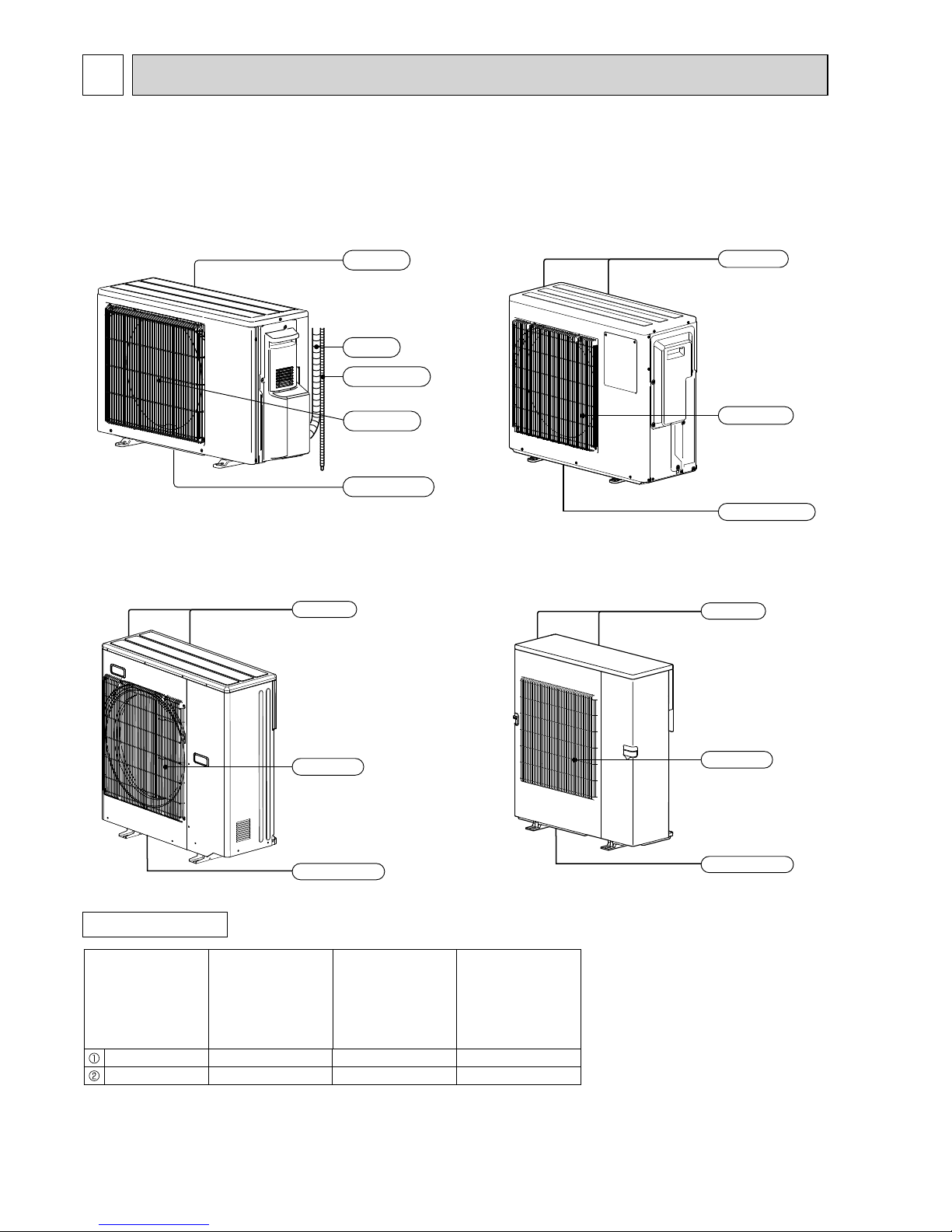
PART NAMES AND FUNCTIONS
2
ACCESSORIES
MXZ-2D33VA
MXZ-2D40VA
MXZ-2D42VA
MXZ-2D53VA
MXZ-2D53VAH
Air inlet
Air outlet
Drain outlet
Piping
Drain hose
(Back and side)
Model
MXZ-2D33VA
MXZ-2D40VA
MXZ-2D42VA
MXZ-2D53VA
MXZ-4D83VA
MXZ-5D102VA
MXZ-3D54VA
MXZ-3D54VA2
MXZ-3D68VA
MXZ-4D72VA
MXZ-6D122VA
Drain socket 1 1 1
Drain cap 2 5
Air outlet
Drain outlet
Air inlet
(Back and side)
MXZ-3D54VA
MXZ-3D54VA2
MXZ-3D68VA
MXZ-4D72VA
MXZ-4D83VA
MXZ-5D102VA
MXZ-6D122VA
Air outlet
Drain outlet
Air inlet
(Back and side)
Air outlet
Drain outlet
Air inlet
(Back and side)
OBH626H
7
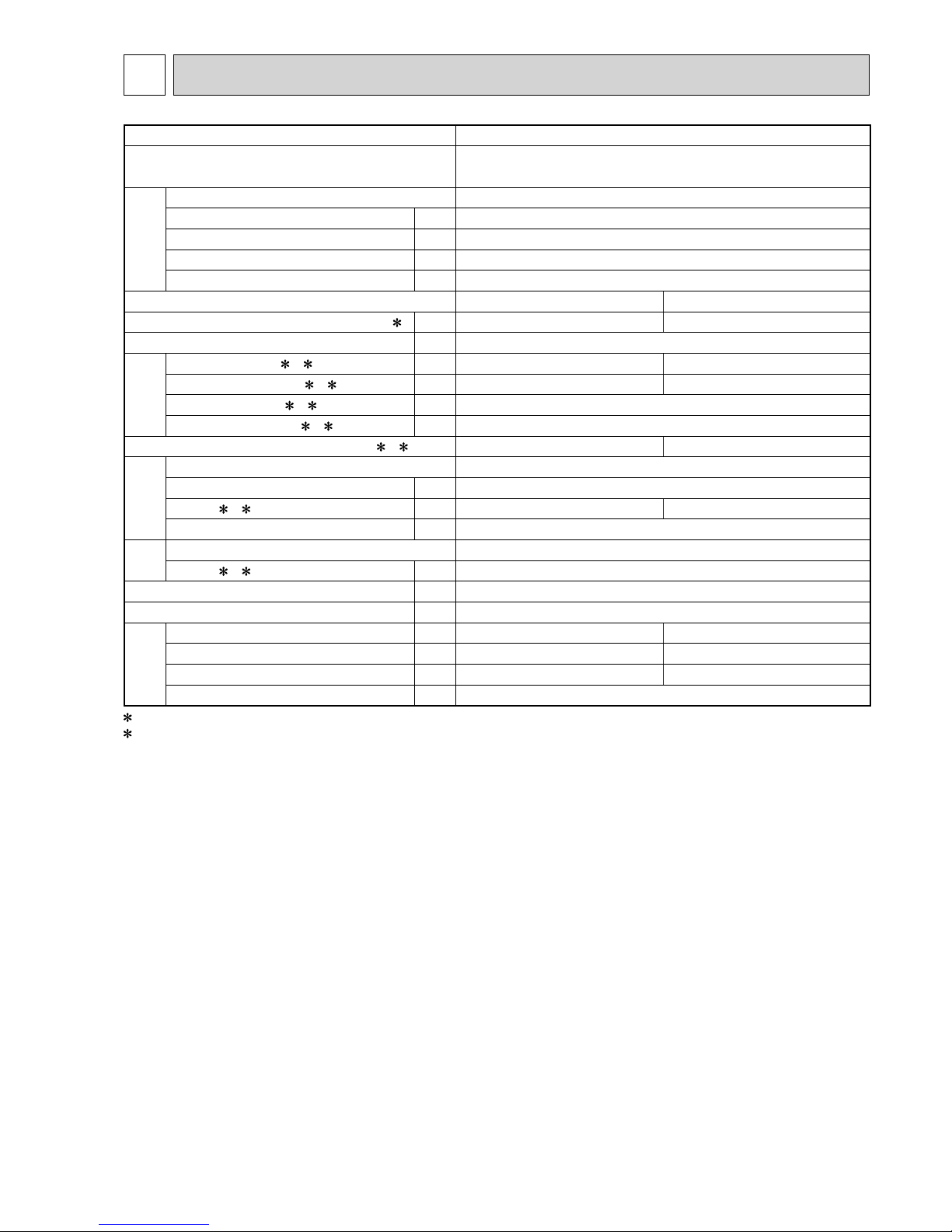
SPECIFICATION
3
Outdoor model MXZ-2D33VA
Outdoor unit power supply
Single phase
230 V, 50 Hz
System
Indoor units number 2
Piping total length m Max. 20
Connecting pipe length m Max. 15
Height difference (Indoor ~ Outdoor) m Refer to 7 REFRIGERANT SYSTEM DIAGRAM.
Height difference (Indoor ~ Indoor) m Refer to 7 REFRIGERANT SYSTEM DIAGRAM.
Function Cooling Heating
Capacity Rated frequency (Min.-Max.)
2 kW 3.3 (1.1 - 3.8) 4.0 (1.0 - 4.1)
Breaker capacity A 15
Electrical
data
Power input (Total) 1, 2 W 900 960
Running current (Total)
1, 2 A 4.3 4.6
Power factor (Total)
1, 2% 90
Starting current (Total)
1, 2 A 4.6
Coeffi cient of performance (C.O.P) (Total)
1, 2 3.67 4.17
Compressor
Model KNB073FFDHC
Output W 800
Current
1, 2 A 4.0 4.2
Refrigeration oil (Model) L 0.32 (NEO22)
Fan
motor
Model RC0J50-FA
Current
1, 2 A 0.35
Dimensions W x H x D mm 800 x 550 x 285
Weight kg 32
Special
remarks
Air fl ow (Rated) m3 /h 1,974 2,022
Sound level (Rated) dB(A) 49 50
Fan speed (Rated) rpm 860 880
Refrigerant fi lling capacity (R410A) kg 1.15
1 Measured under rated operating frequency.
2 When connected with indoor units below.
MSZ-SF15VA + MSZ-EF18VE
NOTE: Test conditions are based on ISO 5151. (Refrigerant piping length (one way): 5 m)
COOLING INDOOR Dry-bulb temperature 27.0 °C Wet-bulb temperature 19.0 °C
OUTDOOR Dry-bulb temperature 35.0 °C Wet-bulb temperature 24.0 °C
HEATING INDOOR Dry-bulb temperature 20.0 °C
OUTDOOR Dry-bulb temperature 7.0 °C Wet-bulb temperature 6.0 °C
OBH626H
8
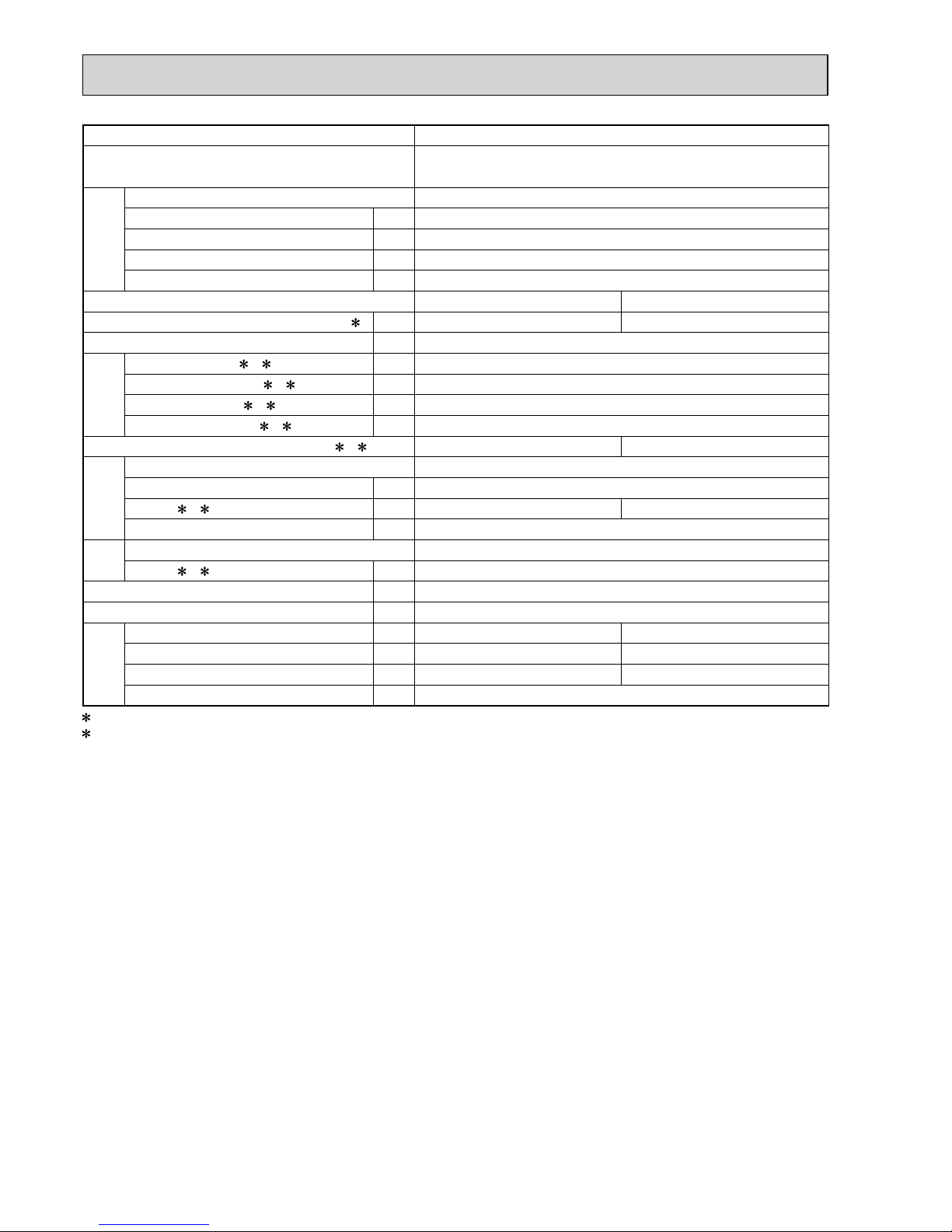
Outdoor model MXZ-2D40VA
Outdoor unit power supply
Single phase
230 V, 50 Hz
System
Indoor units number 2
Piping total length m Max. 30
Connecting pipe length m Max. 20
Height difference (Indoor ~ Outdoor) m Refer to 7 REFRIGERANT SYSTEM DIAGRAM.
Height difference (Indoor ~ Indoor) m Refer to 7 REFRIGERANT SYSTEM DIAGRAM.
Function Cooling Heating
Capacity Rated frequency (Min.-Max.)
2 kW 4.0 (1.1 - 4.3) 4.5 (1.0 - 4.8)
Breaker capacity A 15
Electrical
data
Power input (Total) 1, 2 W 970
Running current (Total)
1, 2 A 4.7
Power factor (Total)
1, 2% 90
Starting current (Total)
1, 2 A 4.7
Coeffi cient of performance (C.O.P) (Total)
1, 2 4.12 4.64
Compressor
Model KNB092FFDHC
Output W 1,100
Current
1, 2 A 4.4 4.2
Refrigeration oil (Model) L 0.32 (NEO22)
Fan
motor
Model RC0J50-FA
Current
1, 2 A 0.35
Dimensions W x H x D mm 800 x 550 x 285
Weight kg 34
Special
remarks
Air fl ow (Rated) m3 /h 1,752 1,662
Sound level (Rated) dB(A) 49 50
Fan speed (Rated) rpm 840 800
Refrigerant fi lling capacity (R410A) kg 1.3
1 Measured under rated operating frequency.
2 When connected with indoor units below.
MSZ-EF18VE + MSZ-EF22VE
NOTE: Test conditions are based on ISO 5151. (Refrigerant piping length (one way): 5 m)
COOLING INDOOR Dry-bulb temperature 27.0 °C Wet-bulb temperature 19.0 °C
OUTDOOR Dry-bulb temperature 35.0 °C Wet-bulb temperature 24.0 °C
HEATING INDOOR Dry-bulb temperature 20.0 °C
OUTDOOR Dry-bulb temperature 7.0 °C Wet-bulb temperature 6.0 °C
OBH626H

9
Outdoor model MXZ-2D42VA
Outdoor unit power supply
Single phase
230 V, 50 Hz
System
Indoor units number 2
Piping total length m Max. 30
Connecting pipe length m Max. 20
Height difference (Indoor ~ Outdoor) m Refer to 7 REFRIGERANT SYSTEM DIAGRAM.
Height difference (Indoor ~ Indoor) m Refer to 7 REFRIGERANT SYSTEM DIAGRAM.
Function Cooling Heating
Capacity Rated frequency (Min.-Max.)
2 kW 4.2 (1.1 - 4.4) 4.5 (1.0 - 4.8)
Breaker capacity A 15
Electrical
data
Power input (Total) 1, 2 W 1,000 930
Running current (Total)
1, 2 A 4.5 4.2
Power factor (Total)
1, 2% 97
Starting current (Total)
1, 2 A 4.5
Coeffi cient of performance (C.O.P) (Total)
1, 2 4.20 4.84
Compressor
Model SNB130FGBHT
Output W 1,150
Current
1, 2 A 4.0 3.6
Refrigeration oil (Model) L 0.45 (NEO22)
Fan
motor
Model RC0J50-FA
Current
1, 2 A 0.35
Dimensions W x H x D mm 800 x 550 x 285
Weight kg 37
Special
remarks
Air fl ow (Rated) m3 /h 1,662 1,998
Sound level (Rated) dB(A) 46 51
Fan speed (Rated) rpm 800 910
Refrigerant fi lling capacity (R410A) kg 1.3
1 Measured under rated operating frequency.
2 When connected with indoor units below.
MSZ-EF18VE + MSZ-EF25VE
NOTE: Test conditions are based on ISO 5151. (Refrigerant piping length (one way): 5 m)
COOLING INDOOR Dry-bulb temperature 27.0 °C Wet-bulb temperature 19.0 °C
OUTDOOR Dry-bulb temperature 35.0 °C Wet-bulb temperature 24.0 °C
HEATING INDOOR Dry-bulb temperature 20.0 °C
OUTDOOR Dry-bulb temperature 7.0 °C Wet-bulb temperature 6.0 °C
OBH626H

10
Outdoor model MXZ-2D53VA MXZ-2D53VAH
Outdoor unit power supply
Single phase
230 V, 50 Hz
System
Indoor units number 2
Piping total length m Max. 30
Connecting pipe length m Max. 20
Height difference (Indoor ~ Outdoor) m Refer to 7 REFRIGERANT SYSTEM DIAGRAM.
Height difference (Indoor ~ Indoor) m Refer to 7 REFRIGERANT SYSTEM DIAGRAM.
Function Cooling Heating
Capacity Rated frequency (Min.-Max.)
2 kW 5.3 (1.1 - 5.6) 6.4 (1.0 - 7.0)
Breaker capacity A 15
Electrical
data
Power input (Total) 1, 2 W 1,540 1,700
Running current (Total)
1, 2 A 6.9 7.6
Power factor (Total)
1, 2% 97
Starting current (Total)
1, 2 A 7.6
Coeffi cient of performance (C.O.P) (Total)
1, 2 3.44 3.76
Compressor
Model SNB130FGBHT
Output W 1,400
Current
1, 2 A 6.6 7.2
Refrigeration oil (Model) L 0.45 (NEO22)
Fan
motor
Model RC0J50-FA
Current
1, 2 A 0.35
Dimensions W x H x D mm 800 x 550 x 285
Weight kg MXZ-2D53VA: 37 MXZ-2D53VAH: 38
Special
remarks
Air fl ow (Rated) m3 /h 1,974 1,998
Sound level (Rated) dB(A) 50 53
Fan speed (Rated) rpm 900 910
Refrigerant fi lling capacity (R410A) kg 1.3
1 Measured under rated operating frequency.
2 When connected with indoor units below.
MSZ-EF18VE + MSZ-EF35VE
NOTE: Test conditions are based on ISO 5151. (Refrigerant piping length (one way): 5 m)
COOLING INDOOR Dry-bulb temperature 27.0 °C Wet-bulb temperature 19.0 °C
OUTDOOR Dry-bulb temperature 35.0 °C Wet-bulb temperature 24.0 °C
HEATING INDOOR Dry-bulb temperature 20.0 °C
OUTDOOR Dry-bulb temperature 7.0 °C Wet-bulb temperature 6.0 °C
OBH626H
11
Outdoor model MXZ-3D54VA MXZ-3D54VA2
Outdoor unit power supply
Single phase
230 V, 50 Hz
System
Indoor units number 2 to 3
Piping total length m Max. 50
Connecting pipe length m Max. 25
Height difference (Indoor ~ Outdoor) m Refer to 7 REFRIGERANT SYSTEM DIAGRAM.
Height difference (Indoor ~ Indoor) m Refer to 7 REFRIGERANT SYSTEM DIAGRAM.
Function Cooling Heating
Capacity Rated frequency (Min.-Max.)
2 kW 5.4 (2.9 - 6.8) 7.0 (2.6 - 9.0)
Breaker capacity A 25
Electrical
data
Power input (Total) 1, 2W
MXZ-3D54VA: 1,390
MXZ-3D54VA2: 1,350
1,590
Running current (Total)
1, 2A
MXZ-3D54VA: 6.1
MXZ-3D54VA2: 5.9
7.0
Power factor (Total)
1, 2% 99
Starting current (Total)
1, 2 A 7.0
Coeffi cient of performance (C.O.P) (Total)
1, 2
MXZ-3D54VA: 3.88
MXZ-3D54VA2: 4.00
4.40
Compressor
Model SNB130FGBH1T
Output W 1,400
Current
1, 2 A 5.72 6.62
Refrigeration oil (Model) L 0.7 (NEO22)
Fan
motor
Model SIC-71FW-F764-1
Current
1, 2 A 0.2
Dimensions W x H x D mm 840 x 710 x 330
Weight kg 57
Special
remarks
Air fl ow (Rated) m3 /h 2,334 2,376
Sound level (Rated) dB(A) 50 53
Fan speed (Rated) rpm 650 660
Refrigerant fi lling capacity (R410A) kg 2.7
1 Measured under rated operating frequency.
2 When connected with indoor units below.
MSZ-EF18VE + MSZ-EF18VE + MSZ-EF18VE
NOTE: Test conditions are based on ISO 5151. (Refrigerant piping length (one way): 5 m)
COOLING INDOOR Dry-bulb temperature 27.0 °C Wet-bulb temperature 19.0 °C
OUTDOOR Dry-bulb temperature 35.0 °C Wet-bulb temperature 24.0 °C
HEATING INDOOR Dry-bulb temperature 20.0 °C
OUTDOOR Dry-bulb temperature 7.0 °C Wet-bulb temperature 6.0 °C
OBH626H
12
Outdoor model MXZ-3D68VA
Outdoor unit power supply
Single phase
230 V, 50 Hz
System
Indoor units number 2 to 3
Piping total length m Max. 60
Connecting pipe length m Max. 25
Height difference (Indoor ~ Outdoor) m Refer to 7 REFRIGERANT SYSTEM DIAGRAM.
Height difference (Indoor ~ Indoor) m Refer to 7 REFRIGERANT SYSTEM DIAGRAM.
Function Cooling Heating
Capacity Rated frequency (Min.-Max.)
2 kW 6.8 (2.9 - 8.4) 8.6 (2.6 - 10.6)
Breaker capacity A 25
Electrical
data
Power input (Total) 1, 2 W 2,190 2,380
Running current (Total)
1, 2 A 9.6 10.5
Power factor (Total)
1, 2% 99
Starting current (Total)
1, 2 A 10.5
Coeffi cient of performance (C.O.P) (Total)
1, 2 3.11 3.61
Compressor
Model SNB172FEGH1T
Output W 1,800
Current
1, 2 A 9.22 10.12
Refrigeration oil (Model) L 0.7 (NEO22)
Fan
motor
Model SIC-71FW-F764-1
Current
1, 2 A 0.2
Dimensions W x H x D mm 840 x 710 x 330
Weight kg 57
Special
remarks
Air fl ow (Rated) m3 /h 2,334 2,376
Sound level (Rated) dB(A) 50 53
Fan speed (Rated) rpm 650 660
Refrigerant fi lling capacity (R410A) kg 2.7
1 Measured under rated operating frequency.
2 When connected with indoor units below.
MSZ-EF18VE + MSZ-EF25VE + MSZ-EF25VE
NOTE: Test conditions are based on ISO 5151. (Refrigerant piping length (one way): 5 m)
COOLING INDOOR Dry-bulb temperature 27.0 °C Wet-bulb temperature 19.0 °C
OUTDOOR Dry-bulb temperature 35.0 °C Wet-bulb temperature 24.0 °C
HEATING INDOOR Dry-bulb temperature 20.0 °C
OUTDOOR Dry-bulb temperature 7.0 °C Wet-bulb temperature 6.0 °C
OBH626H

13
Outdoor model MXZ-4D72VA
Outdoor unit power supply
Single phase
230 V, 50 Hz
System
Indoor units number 2 to 4
Piping total length m Max. 60
Connecting pipe length m Max. 25
Height difference (Indoor ~ Outdoor) m Refer to 7 REFRIGERANT SYSTEM DIAGRAM.
Height difference (Indoor ~ Indoor) m Refer to 7 REFRIGERANT SYSTEM DIAGRAM.
Function Cooling Heating
Capacity Rated frequency (Min.-Max.)
2 kW 7.2 (3.7 - 8.8) 8.6 (3.4 - 10.7)
Breaker capacity A 25
Electrical
data
Power input (Total) 1, 2 W 2,250 2,280
Running current (Total)
1, 2 A 9.9 10.0
Power factor (Total)
1, 2% 99
Starting current (Total)
1, 2 A 10.0
Coeffi cient of performance (C.O.P) (Total)
1, 2 3.20 3.77
Compressor
Model SNB172FEGH1T
Output W 2,000
Current
1, 2 A 9.46 9.56
Refrigeration oil (Model) L 0.7 (NEO22)
Fan
motor
Model SIC-71FW-F764-1
Current
1, 2 A 0.2
Dimensions W x H x D mm 840 x 710 x 330
Weight kg 58
Special
remarks
Air fl ow (Rated) m3 /h 2,334 2,376
Sound level (Rated) dB(A) 50 53
Fan speed (Rated) rpm 650 660
Refrigerant fi lling capacity (R410A) kg 2.7
1 Measured under rated operating frequency.
2 When connected with indoor units below.
MSZ-EF18VE + MSZ-EF18VE + MSZ-EF18VE + MSZ-EF18VE
NOTE: Test conditions are based on ISO 5151. (Refrigerant piping length (one way): 5 m)
COOLING INDOOR Dry-bulb temperature 27.0 °C Wet-bulb temperature 19.0 °C
OUTDOOR Dry-bulb temperature 35.0 °C Wet-bulb temperature 24.0 °C
HEATING INDOOR Dry-bulb temperature 20.0 °C
OUTDOOR Dry-bulb temperature 7.0 °C Wet-bulb temperature 6.0 °C
OBH626H

14
Outdoor model MXZ-4D83VA
Outdoor unit power supply
Single phase
230 V, 50 Hz
System
Indoor units number 2 to 4
Piping total length m Max. 70
Connecting pipe length m Max. 25
Height difference (Indoor ~ Outdoor) m Refer to 7 REFRIGERANT SYSTEM DIAGRAM.
Height difference (Indoor ~ Indoor) m Refer to 7 REFRIGERANT SYSTEM DIAGRAM.
Function Cooling Heating
Capacity Rated frequency (Min.-Max.)
2 kW 8.3 ( 3.7 - 9.2 ) 9.0 ( 3.4 - 11.6 )
Breaker capacity A 25
Electrical
data
Power input (Total) 1, 2 W 2,830 2,420
Running current (Total)
1, 2 A 12.4 10.6
Power factor (Total)
1, 2% 99
Starting current (Total)
1, 2 A 12.4
Coeffi cient of performance (C.O.P) (Total)
1, 2 2.93 3.72
Compressor
Model TNB220FMCH
Output W 2,100
Current
1, 2 A 11.76 9.96
Refrigeration oil (Model) L 0.87 (NEO22)
Fan
motor
Model RC0J60-CC
Current
1, 2 A 0.4
Dimensions W x H x D mm 900 x 915 x 320
Weight kg 69
Special
remarks
Air fl ow (Rated) m3 /h 2,526 2,628
Sound level (Rated) dB(A) 49 50
Fan speed (Rated) rpm 600 620
Refrigerant fi lling capacity (R410A) kg 3.5
1 Measured under rated operating frequency.
2 When connected with indoor units below.
MSZ-EF18VE + MSZ-EF18VE + MSZ-EF22VE + MSZ-EF25VE
NOTE: Test conditions are based on ISO 5151. (Refrigerant piping length (one way): 5 m)
COOLING INDOOR Dry-bulb temperature 27.0 °C Wet-bulb temperature 19.0 °C
OUTDOOR Dry-bulb temperature 35.0 °C Wet-bulb temperature 24.0 °C
HEATING INDOOR Dry-bulb temperature 20.0 °C
OUTDOOR Dry-bulb temperature 7.0 °C Wet-bulb temperature 6.0 °C
OBH626H
15
Outdoor model MXZ-5D102VA
Outdoor unit power supply
Single phase
230 V, 50 Hz
System
Indoor units number 2 to 5
Piping total length m Max. 80
Connecting pipe length m Max. 25
Height difference (Indoor ~ Outdoor) m Refer to 7 REFRIGERANT SYSTEM DIAGRAM.
Height difference (Indoor ~ Indoor) m Refer to 7 REFRIGERANT SYSTEM DIAGRAM.
Function Cooling Heating
Capacity Rated frequency (Min.-Max.)
2 kW 10.2 ( 3.9 - 11.0 ) 10.5 ( 4.1 - 14.0 )
Breaker capacity A 25
Electrical
data
Power input (Total) 1, 2 W 3,910 2,900
Running current (Total)
1, 2 A 17.2 12.7
Power factor (Total)
1, 2% 99
Starting current (Total)
1, 2 A 17.2
Coeffi cient of performance (C.O.P) (Total)
1, 2 2.61 3.62
Compressor
Model TNB220FMCH
Output W 2,700
Current
1, 2 A 16.5 12.0
Refrigeration oil (Model) L 0.87 (NEO22)
Fan
motor
Model RC0J60-CC
Current
1, 2 A 0.4
Dimensions W x H x D mm 900 x 915 x 320
Weight kg 70
Special
remarks
Air fl ow (Rated) m3 /h 3,396 3,558
Sound level (Rated) dB(A) 53 55
Fan speed (Rated) rpm 780 810
Refrigerant fi lling capacity (R410A) kg 4.0
1 Measured under rated operating frequency.
2 When connected with indoor units below.
MSZ-EF18VE + MSZ-EF18VE + MSZ-EF22VE + MSZ-EF22VE + MSZ-EF22VE
NOTE: Test conditions are based on ISO 5151. (Refrigerant piping length (one way): 5 m)
COOLING INDOOR Dry-bulb temperature 27.0 °C Wet-bulb temperature 19.0 °C
OUTDOOR Dry-bulb temperature 35.0 °C Wet-bulb temperature 24.0 °C
HEATING INDOOR Dry-bulb temperature 20.0 °C
OUTDOOR Dry-bulb temperature 7.0 °C Wet-bulb temperature 6.0 °C
OBH626H

16
Outdoor model MXZ-6D122VA
Outdoor unit power supply
Single phase
230 V, 50 Hz
System
Indoor units number 2 to 6
Piping total length m Max. 80
Connecting pipe length m Max. 25
Height difference (Indoor ~ Outdoor) m Refer to 7 REFRIGERANT SYSTEM DIAGRAM.
Height difference (Indoor ~ Indoor) m Refer to 7 REFRIGERANT SYSTEM DIAGRAM.
Function Cooling Heating
Capacity Rated frequency (Min.-Max.)
2 kW 12.2 ( 3.5 - 13.5 ) 14.0 ( 3.5 - 16.5 )
Breaker capacity A 32
Electrical
data
Power input (Total) 1, 2 W 3,660 3,310
Running current (Total)
1, 2 A 16.1 14.5
Power factor (Total)
1, 2% 99
Starting current (Total)
1, 2 A 17.2
Coeffi cient of performance (C.O.P) (Total)
1, 2 3.33 4.23
Compressor
Model MNB33FBTM-L
Output W 1,700
Current
1, 2 A 15.26 12.94
Refrigeration oil (Model) L 1.10 (FV50S)
Fan
motor
Model SIC-81FW-D888-9
Current
1, 2 A 0.3
Dimensions W x H x D mm 950 x 1,048 x 330
Weight kg 88
Special
remarks
Air fl ow (Rated) m3 /h 3,780 4,620
Sound level (Rated) dB(A) 55 57
Fan speed (Rated) rpm 650 750
Refrigerant fi lling capacity (R410A) kg 4.0
1 Measured under rated operating frequency.
2 When connected with indoor units below.
MSZ-EF22VE +MSZ-EF22VE +MSZ-EF22VE +MSZ-EF22VE +MSZ-EF22VE +MSZ-EF22VE
NOTE: Test conditions are based on ISO 5151. (Refrigerant piping length (one way): 5 m)
COOLING INDOOR Dry-bulb temperature 27.0 °C Wet-bulb temperature 19.0 °C
OUTDOOR Dry-bulb temperature 35.0 °C Wet-bulb temperature 24.0 °C
HEATING INDOOR Dry-bulb temperature 20.0 °C
OUTDOOR Dry-bulb temperature 7.0 °C Wet-bulb temperature 6.0 °C
OBH626H
17
90
80
70
60
50
40
30
20
10
63 125 250 500 1000 2000 4000 8000
APPROXIMATE
THRESHOLD OF
HEARING FOR
CONTINUOUS
NOISE
NC-60
NC-50
NC-40
NC-30
NC-20
NC-70
OCTAVE BAND SOUND PRESSURE LEVEL, dB re 0.0002 MICRO BAR
BAND CENTER FREQUENCIES, Hz
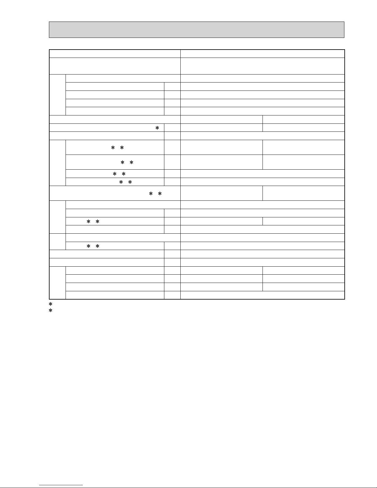
CoolingHigh
FUNCTION
FAN SPEED
HeatingHigh
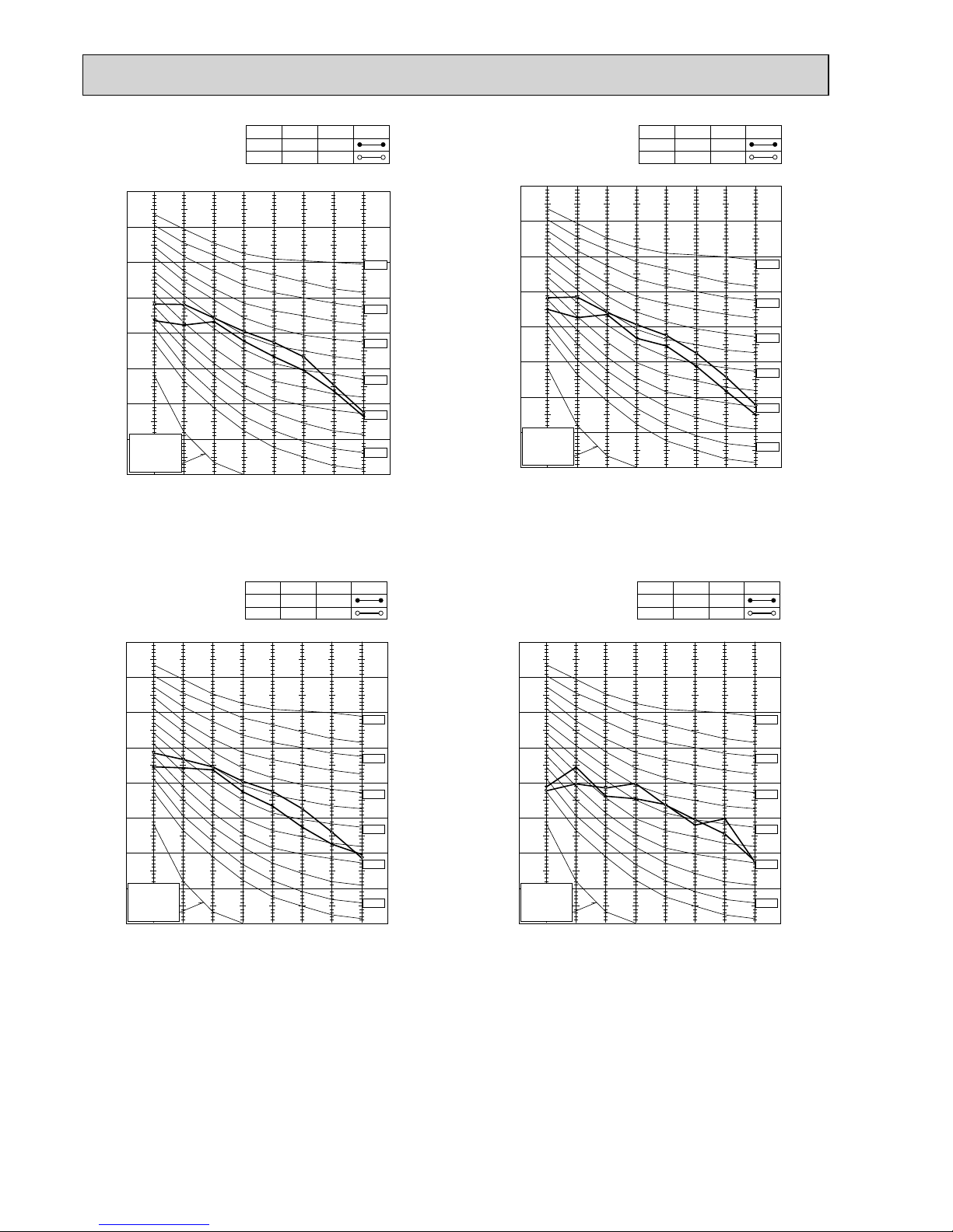
49
SPL(dB(A))50LINE
90
80
70
60
50
40
30
20
10
63 125 250 500 1000 2000 4000 8000
NC-60
NC-50
NC-40
NC-30
NC-20
NC-70
OCTAVE BAND SOUND PRESSURE LEVEL, dB re 0.0002 MICRO BAR
BAND CENTER FREQUENCIES, Hz
APPROXIMATE
THRESHOLD OF
HEARING FOR
CONTINUOUS
NOISE
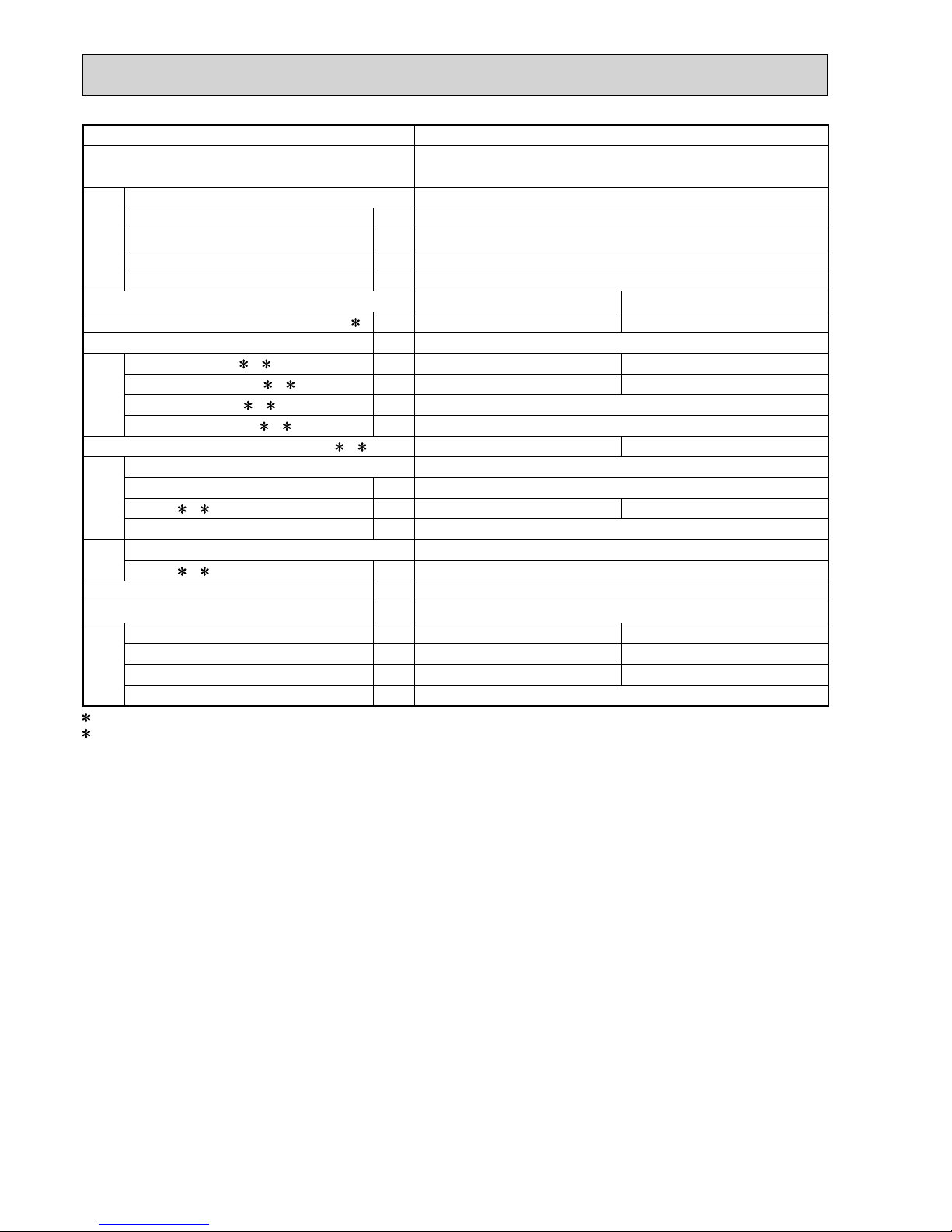
CoolingHigh
FUNCTION
FAN SPEED
HeatingHigh
46
SPL(dB(A))51LINE
90
80
70
60
50
40
30
20
10
63 125 250 500 1000 2000 4000 8000
NC-60
NC-50
NC-40
NC-30
NC-20
NC-70
OCTAVE BAND SOUND PRESSURE LEVEL, dB re 0.0002 MICRO BAR
BAND CENTER FREQUENCIES, Hz
APPROXIMATE
THRESHOLD OF
HEARING FOR
CONTINUOUS
NOISE
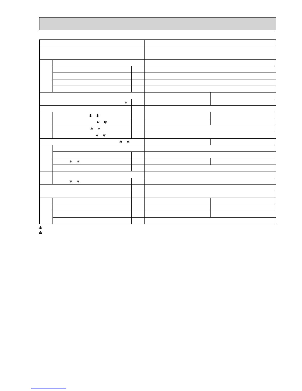
CoolingHigh
FUNCTION
FAN SPEED
HeatingHigh
49
SPL(dB(A))50LINE
90
80
70
60
50
40
30
20
10
63 125 250 500 1000 2000 4000 8000
NC-60
NC-50
NC-40
NC-30
NC-20
NC-70
OCTAVE BAND SOUND PRESSURE LEVEL, dB re 0.0002 MICRO BAR
BAND CENTER FREQUENCIES, Hz
APPROXIMATE
THRESHOLD OF
HEARING FOR
CONTINUOUS
NOISE
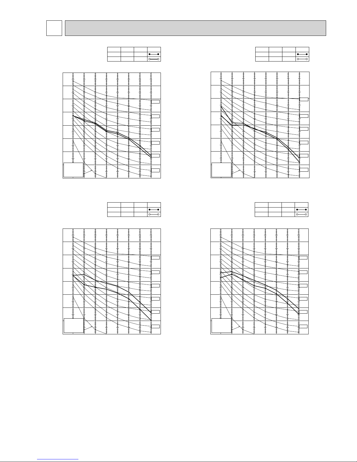
CoolingHigh
FUNCTION
FAN SPEED
HeatingHigh
50
SPL(dB(A))53LINE
NOISE CRITERIA CURVES
4
MXZ-2D53VA
MXZ-2D53VAH
MXZ-2D33VA
MXZ-2D42VA
MXZ-2D40VA
OBH626H
18
90
80
70
60
50
40
30
20
10
63 125 250 500 1000 2000 4000 8000
APPROXIMATE
THRESHOLD OF
HEARING FOR
CONTINUOUS
NOISE
NC-60
NC-50
NC-40
NC-30
NC-20
NC-70
OCTAVE BAND SOUND PRESSURE LEVEL, dB re 0.0002 MICRO BAR
BAND CENTER FREQUENCIES, Hz
CoolingHigh
FUNCTION
FAN SPEED
HeatingHigh
50
SPL(dB(A))53LINE
90
80
70
60
50
40
30
20
10
63 125 250 500 1000 2000 4000 8000
APPROXIMATE
THRESHOLD OF
HEARING FOR
CONTINUOUS
NOISE
NC-60
NC-50
NC-40
NC-30
NC-20
NC-70
OCTAVE BAND SOUND PRESSURE LEVEL, dB re 0.0002 MICRO BAR
BAND CENTER FREQUENCIES, Hz
CoolingHigh
FUNCTION
FAN SPEED
HeatingHigh
50
SPL(dB(A))53LINE
90
80
70
60
50
40
30
20
10
63 125 250 500 1000 2000 4000 8000
APPROXIMATE
THRESHOLD OF
HEARING FOR
CONTINUOUS
NOISE
NC-60
NC-50
NC-40
NC-30
NC-20
NC-70
OCTAVE BAND SOUND PRESSURE LEVEL, dB re 0.0002 MICRO BAR
BAND CENTER FREQUENCIES, Hz
CoolingHigh
FUNCTION
FAN SPEED
HeatingHigh
50
SPL(dB(A))53LINE
90
80
70
60
50
40
30
20
10
63 125 250 500 1000 2000 4000 8000
APPROXIMATE
THRESHOLD OF
HEARING FOR
CONTINUOUS
NOISE
NC-60
NC-50
NC-40
NC-30
NC-20
NC-70
OCTAVE BAND SOUND PRESSURE LEVEL, dB re 0.0002 MICRO BAR
BAND CENTER FREQUENCIES, Hz
CoolingHigh
FUNCTION
FAN SPEED
HeatingHigh
48
SPL(dB(A))51LINE
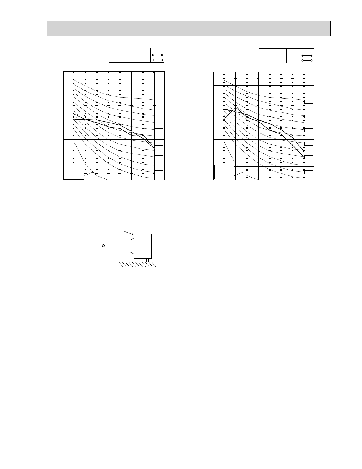
MXZ-3D54VA
MXZ-3D54VA2
MXZ-3D68VA
MXZ-4D72VA MXZ-4D83VA
OBH626H
19
90
80
70
60
50
40
30
20
10
63 125 250 500 1000 2000 4000 8000
APPROXIMATE
THRESHOLD OF
HEARING FOR
CONTINUOUS
NOISE
NC-60
NC-50
NC-40
NC-30
NC-20
NC-70
OCTAVE BAND SOUND PRESSURE LEVEL, dB re 0.0002 MICRO BAR
BAND CENTER FREQUENCIES, Hz
CoolingHigh
FUNCTION
FAN SPEED
HeatingHigh
48
SPL(dB(A))51LINE
90
80
70
60
50
40
30
20
10
63 125 250 500 1000 2000 4000 8000
APPROXIMATE
THRESHOLD OF
HEARING FOR
CONTINUOUS
NOISE
NC-60
NC-50
NC-40
NC-30
NC-20
NC-70
OCTAVE BAND SOUND PRESSURE LEVEL, dB re 0.0002 MICRO BAR
BAND CENTER FREQUENCIES, Hz
CoolingHigh
FUNCTION
FAN SPEED
HeatingHigh
55
SPL(dB(A))57LINE
MXZ-5D102VA MXZ-6D122VA
OUTDOOR UNIT
MICROPHONE
1m
Test conditions
Cooling :Dry-bulb temperature 35°C Wet-bulb temperature 24°C
Heating :Dry-bulb temperature 7°C Wet-bulb temperature 6°C
OBH626H
20
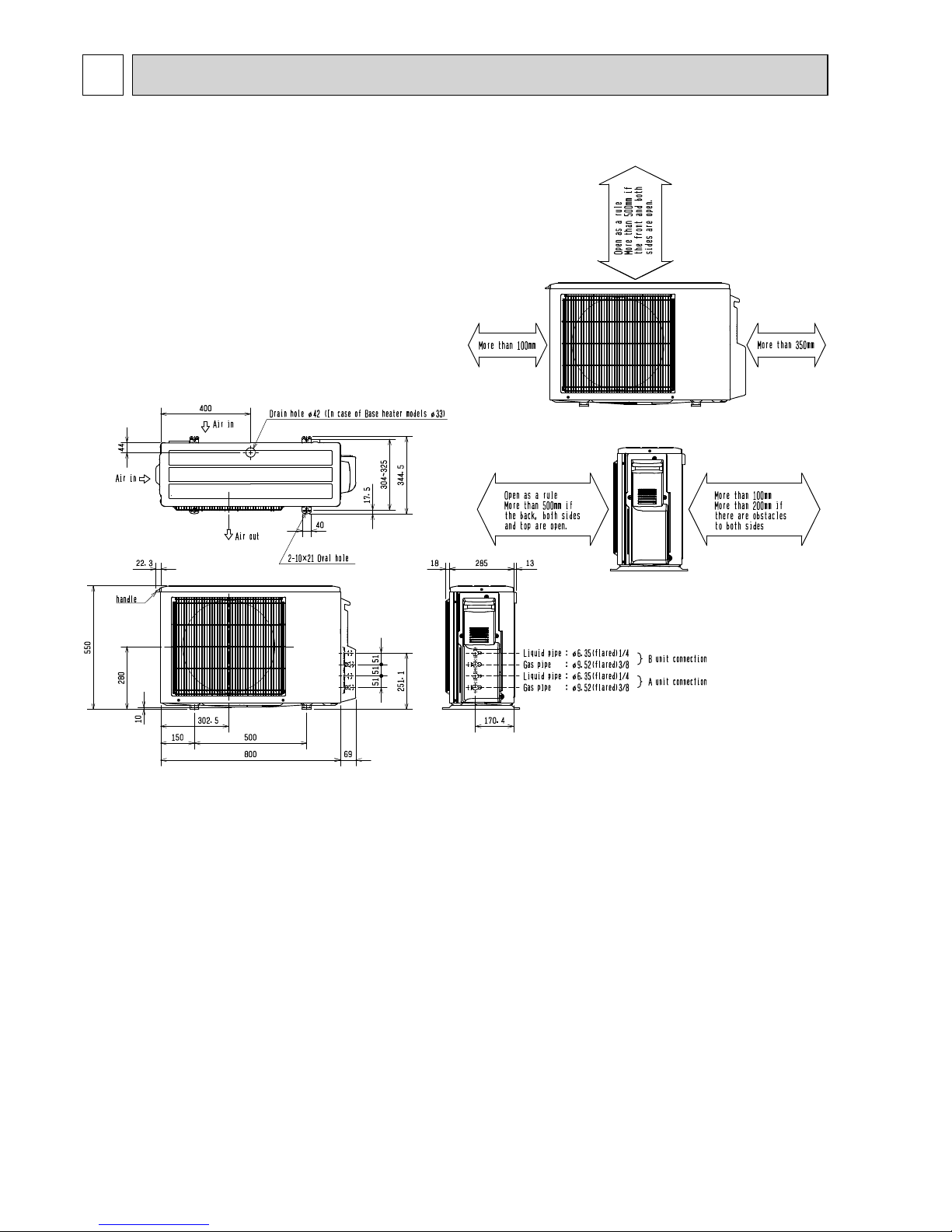
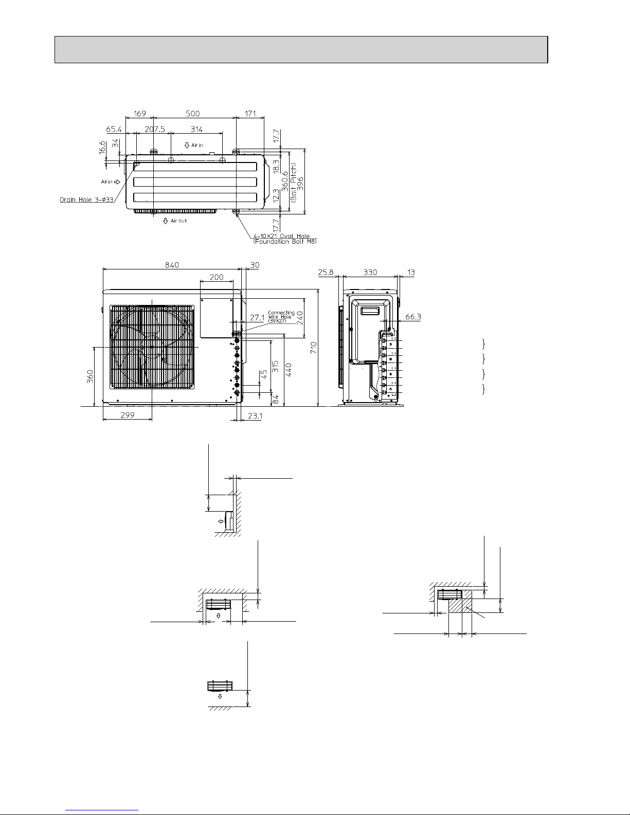
OUTLINES AND DIMENSIONS
5
MXZ-2D33VA MXZ-2D40VA MXZ-2D42VA MXZ-2D53VA MXZ-2D53VAH
Unit: mm
OBH626H
21
1.Installation space
Note : Leave front and both sides
free of obstruction.
Note : Leave rear, overhead and
both sides free of obstruction.
500 or more
100 or more
Note : Leave front and overhead
free of obstruction.
100 or more
350 or more
200 or more
500 or more
2.Service space
100 or more
500 or more
350 or more
350 or more
100 or more
Service space
Liquid pipe : Ø6.35(flared)1/4
C unit connection
B unit connection
A unit connection
Gas pipe : Ø9.52(flared)3/8
Liquid pipe : Ø6.35(flared)1/4
Gas pipe : Ø9.52(flared)3/8
Liquid pipe : Ø6.35(flared)1/4
Gas pipe : Ø9.52(flared)3/8
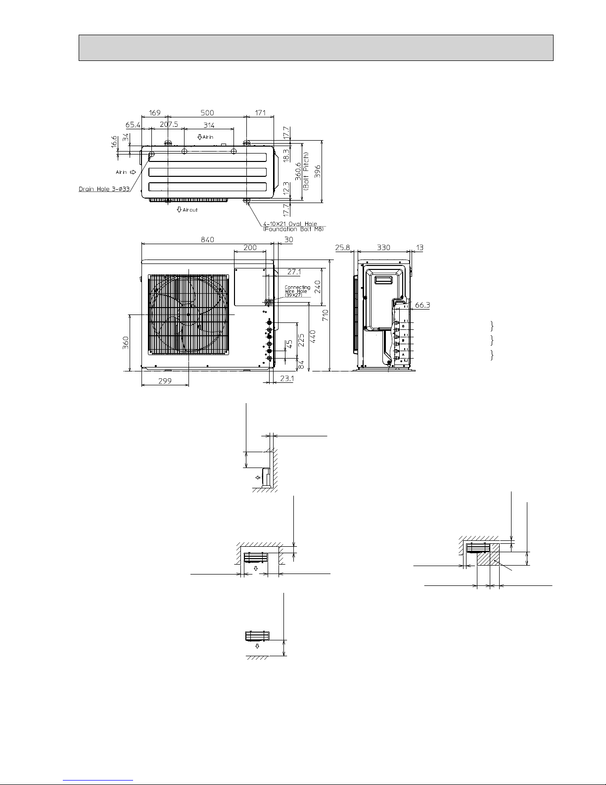
MXZ-3D54VA MXZ-3D54VA2 MXZ-3D68VA
Unit: mm
OBH626H
22
MXZ-4D72VA
Unit: mm
1.Installation space
Note : Leave front and both sides
free of obstruction.
Note : Leave rear, overhead and
both sides free of obstruction.
500 or more
100 or more
Note : Leave front and overhead
free of obstruction.
100 or more
350 or more
200 or more
500 or more
2.Service space
100 or more
500 or more
350 or more
350 or more
100 or more
Service space
Liquid pipe : Ø6.35(flared)1/4
D unit connection
C unit connection
B unit connection
Gas pipe : Ø9.52(flared)3/8
Liquid pipe : Ø6.35(flared)1/4
Gas pipe : Ø9.52(flared)3/8
Liquid pipe : Ø6.35(flared)1/4
Gas pipe : Ø9.52(flared)3/8
A unit connection
Liquid pipe : Ø6.35(flared)1/4
Gas pipe : Ø12.7(flared)1/2
OBH626H

23
MXZ-4D83VA
MXZ-5D102VA
Unit: mm
Liquid pipe : Ø6.35(flared)1/4
E unit connection
(MXZ-5D102VA)
D unit connection
C unit connection
B unit connection
Gas pipe : Ø9.52(flared)3/8
Liquid pipe : Ø6.35(flared)1/4
Gas pipe : Ø9.52(flared)3/8
Liquid pipe : Ø6.35(flared)1/4
Gas pipe : Ø9.52(flared)3/8
Liquid pipe : Ø6.35(flared)1/4
Gas pipe : Ø9.52(flared)3/8
A unit connection
Liquid pipe : Ø6.35(flared)1/4
Gas pipe : Ø12.7(flared)1/2
1.Installation space
Note : Leave front and both sides
free of obstruction.
Note : Leave rear, overhead and
both sides free of obstruction.
Air out
42
200 200500
315
355
(Bolt pitch)
387
40
27
16
16
11
24
Drain hole 42
(Fondation bolt M10)
(Fondation bolt M10)
2-U Shaped notched hole
2-12 x 36 Oval hole
Air in
Air in
32025 10
88
475
317
900
Handle
Handle
915
500 or more
100 or more
Note : Leave front and overhead
free of obstruction.
100 or more
350 or more
200 or more
500 or more
2.Service space
100 or more
500 or more
350 or more
350 or more
100 or more
Service space
23
612
147
405
45
Indoor and
outdoor
connect wiring
(35 x 53) hole
OBH626H

24
MXZ6D122VA
Unit: mm
34
468134
43
Handle
Air Intake
Handle
330
70
25 15
6-ø33 Drain Hole
Air in
Air out
Air in
(Foundation Bolt M10)
2-U Shaped Notched Hole
(Foundation Bolt M10)
2-12×36 Oval Hole
(Bolt pitch)
1169780250
51
71
134
40
62
10
10
10
10
175 600 175
10
10
417
31 16370
36
51
Handle
Handle
Handle
361
563
1048
950
Liquid pipe : Ø6.35(flared)1/4
E unit
connection
D unit
connection
C unit
connection
B unit
connection
A unit
connection
F unit
connection
Gas pipe : Ø9.52(flared)3/8
Liquid pipe : Ø6.35(flared)1/4
Gas pipe : Ø9.52(flared)3/8
Liquid pipe : Ø6.35(flared)1/4
Gas pipe : Ø9.52(flared)3/8
Liquid pipe : Ø6.35(flared)1/4
Gas pipe : Ø9.52(flared)3/8
Liquid pipe : Ø6.35(flared)1/4
Gas pipe : Ø9.52(flared)3/8
Liquid pipe : Ø6.35(flared)1/4
Gas pipe : Ø12.7(flared)1/2
SERVICE SPACE
1.FREE SPACE
2.SERVICE SPACE
100 or more
200 or more
350 or more
500 or more
100 or more
100 or more
350 or more 350 or more
500 or more
100 or more
500 or more
OBH626H

71
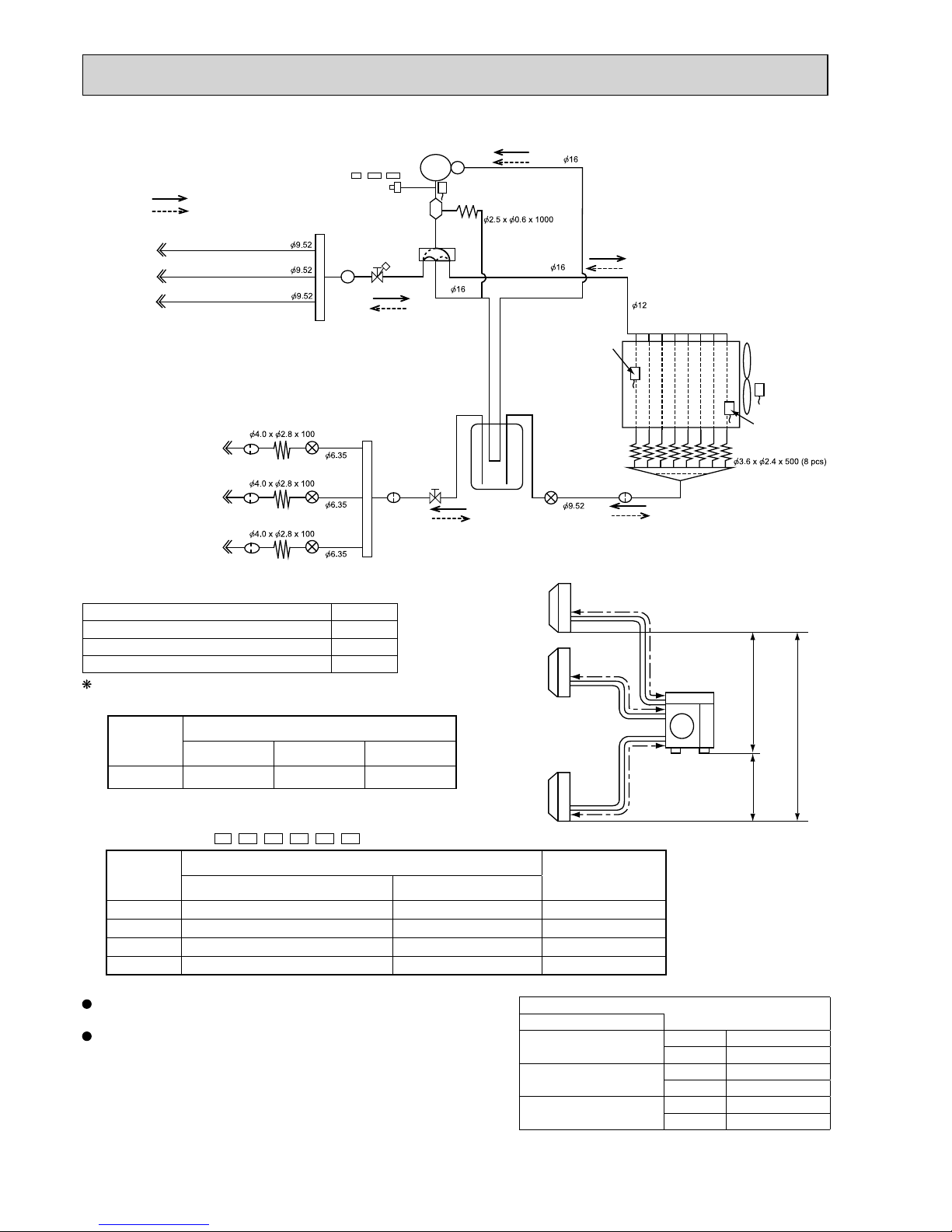
REFRIGERANT SYSTEM DIAGRAM
7
a
b
Outdoor
unit
Indoor
units
10 m
10 m
10 m
Max.
Height
difference
Stop valve
(with strainer #100)
LEV A
LEV B
Compressor
Defrost
thermistor
RT61
Muffler
4-way valve
Indoor unit
B
Indoor unit
A
Indoor unit
A
Indoor unit
B
Capillary tube
Capillary tube
Strainer
#100
Stop valve
(with strainer #100)
R.V. coil
OFF
ON
Refrigerant flow in cooling
Refrigerant flow in heating
Ambient
temperature
thermistor
RT65
Outdoor heat
exchanger
temperature
thermistor
RT68
FAN- OUT
HEX-OUT
Discharge
temperature
thermistor RT62
Stop valve
(with service port)
Stop valve
(with service port)
Sub muffler
Refrigerant pipe diameter is different according to indoor unit to be connected. When using extension pipes, refer to the
table below.
UNIT: mm
MXZ-2D33VA
UNIT: mm (inch)
Outdoor unit union diameter
For
Indoor unit A
Liquid 6.35(1/4)
Gas 9.52(3/8)
Indoor unit B
Liquid 6.35(1/4)
Gas 9.52(3/8)
MAX REFRIGERANT PIPING LENGTH
Piping length each indoor unit (a, b) 15 m
Total piping length (a+b) 20 m
Bending point for each unit 15
Total bending point 20
It is irrelevant which unit is higher.
ADDITIONAL REFRIGERANT CHARGE
Outdoor unit
precharged
(g)
Refrigerant piping length (one way, 2 unit total)
20 m
1,150 0
WHEN CONNECTING TO MFZ-KJ SERIES INDOOR UNIT
MXZ-2D33VA -E2/
ER2/ET2
/E3/
ER3/ET3
No. of
MFZ-KJ
indoor units
Refrigerant piping length (L)
Maximum amount
of refrigerant
~ 20 m
None Charge-less (1,150 g) 1,150 g
1 unit 100 g additional charge (1,250 g) 1,250 g
2 units Not available -
OBH626H

72
Refrigerant pipe diameter is different according to indoor unit to be connected. When using extension pipes, refer to the
table below.
UNIT: mm (inch)
Piping length each indoor unit (a, b) 20 m
Total piping length (a+b) 30 m
Bending point for each unit 20
Total bending point 30
MXZ-2D40VA
MAX REFRIGERANT PIPING LENGTH
a
b
Outdoor
unit
Indoor
units
15 m
10 m
15 m
Refrigerant piping length (one way, 2 unit total)
Calculation : Xg = 20 g/m x (Refrigerant piping length (m) - 20)
Outdoor unit
precharged
(g)
30 m
200
20 m
0
1,300
Max.
Height
difference
Outdoor unit union diameter
For
Indoor unit A
Liquid 6.35(1/4)
Gas 9.52(3/8)
Indoor unit B
Liquid 6.35(1/4)
Gas 9.52(3/8)
Stop valve
(with strainer #100)
LEV A
LEV B
Compressor
Muffler
4-way valve
Indoor unit
B
Indoor unit
A
Indoor unit
A
Indoor unit
B
Capillary tube
Capillary tube
Stop valve
(with strainer #100)
Refrigerant flow in cooling
Refrigerant flow in heating
Discharge
temperature
thermistor RT62
Stop valve
(with service port)
Stop valve
(with service port)
Defrost
thermistor
RT61
Distributor
Capillary tube
Strainer
#100
Ambient
temperature
thermistor
RT65
Outdoor heat
exchanger
temperature
thermistor
RT68
FAN- OUT
HEX-OUT
Sub muffler
It is irrelevant which unit is higher.
ADDITIONAL REFRIGERANT CHARGE
UNIT: mm
OBH626H

73
Stop valve
(with strainer #100)
LEV A
LEV B
Compressor
Defrost
thermistor
RT61
Distributor
Muffler
4-way valve
Indoor unit
B
Indoor unit
A
Indoor unit
A
Indoor unit
B
Capillary tube
Capillary tube
Capillary tube
Strainer
#100
Stop valve
(with strainer #100)
R.V. coil
OFF
ON
Refrigerant flow in cooling
Refrigerant flow in heating
Ambient
temperature
thermistor
RT65
Outdoor heat
exchanger
temperature
thermistor
RT68
FAN- OUT
HEX-OUT
Discharge
temperature
thermistor RT62
Stop valve
(with service port)
Stop valve
(with service port)
Sub muffler
UNIT: mm
MXZ-2D42VA MXZ-2D53VA MXZ-2D53VAH
MAX REFRIGERANT PIPING LENGTH
Piping length each indoor unit (a, b) 20 m
Total piping length (a+b) 30 m
Bending point for each unit 20
Total bending point 30
It is irrelevant which unit is higher.
a
b
Outdoor
unit
Indoor
units
15 m
10 m
15 m
Max.
Height
dif
ference
UNIT: mm (inch)
Outdoor unit union diameter
For
Indoor unit A
Liquid 6.35(1/4)
Gas 9.52(3/8)
Indoor unit B
Liquid 6.35(1/4)
Gas 9.52(3/8)
ADDITIONAL REFRIGERANT CHARGE
Outdoor unit
precharged
(g)
Refrigerant piping length (one way, 2 unit total)
20 m 30 m
1,300 0 200
Calculation : Xg = 20 g/m x (Refrigerant piping length (m) - 20)
WHEN CONNECTING TO MFZ-KJ SERIES INDOOR UNIT
MXZ-2D42VA -E2/E3/
ER3/ET2/ET3
MXZ-2D53VA -E2/E3/
ER2/ER3/ET2/ET3
MXZ-2D53VAH -E2/E3/
ER2/ER3
No. of
MFZ-KJ
indoor units
Refrigerant piping length (L)
Maximum amount
of refrigerant
~ 20 m ~ 30 m
None Charge-less (1,300 g) (L-20) x 20 g/m 1,500 g
1 unit 100 g additional charge (1,400 g) 100 g + (L-20) x 20 g/m 1,600 g
2 units 200 g additional charge (1,500 g) 200 g + (L-20) x 20 g/m 1,700 g
Refrigerant pipe diameter is different according to indoor unit to be
connected. When using extension pipes, refer to the right table.
When diameter of refrigerant pipe is different from that of outdoor
unit union, use optional Different-diameter pipe.
For further information on Different-diameter pipe, refer to "PARTS
CATALOG".
OBH626H
74
Strainer
#100
Power
receiver
LEV A
LEV B
LEV C
Oil separator
Compressor
Defrost
thermistor
RT61
Distributor
Muffler
4-way valve
LEV E
Indoor unit
C
Indoor unit
B
Indoor unit
A
Indoor unit
A
Indoor unit
B
Indoor unit
C
Capillary tube
Capillary tube
Capillary tube
Capillary tube
Capillary tube
Discharge
temperature
thermistor RT62
Strainer
#100
Strainer
#100
Strainer
#100
R.V. coil
OFF
ON
Refrigerant flow in cooling
Refrigerant flow in heating
Ambient
temperature
thermistor
RT65
Outdoor heat
exchanger
temperature
thermistor
RT68
FAN- OUT
HEX-OUT
Strainer
#100
Stop valve with
service port
Stop valve
High-pressure switch
(MXZ-3D54VA2- , , only)
E3 ET3ER3
UNIT: mm (inch)
UNIT: mm
MXZ-3D54VA MXZ-3D54VA2
MAX REFRIGERANT PIPING LENGTH
Outdoor unit union diameter
For
Indoor unit A
Liquid 6.35(1/4)
Gas 9.52(3/8)
Indoor unit B
Liquid 6.35(1/4)
Gas 9.52(3/8)
Indoor unit C
Liquid 6.35(1/4)
Gas 9.52(3/8)
a
b
c
Outdoor
unit
Indoor
units
15 m
10 m
15 m
Max.
Height
difference
Piping length each indoor unit (a, b, c) 25 m
Total piping length (a+b+c) 50 m
Bending point for each unit 25
Total bending point 50
It is irrelevant which unit is higher.
Refrigerant pipe diameter is different according to indoor unit to be
connected. When using extension pipes, refer to the right table.
When diameter of refrigerant pipe is different from that of outdoor
unit union, use optional Different-diameter pipe.
For further information on Different-diameter pipe, refer to "PARTS
CATALOG".
ADDITIONAL REFRIGERANT CHARGE
Outdoor unit
precharged
(g)
Refrigerant piping length (one way, 3 unit total)
40 m 50 m 60 m
2,700 0 200 400
Calculation : Xg = 20 g/m x (Refrigerant piping length (m) - 40)
WHEN CONNECTING TO MFZ-KJ SERIES INDOOR UNIT
MXZ-3D54VA2 -E2/E3/
ER2
/
ER3
/
ET2/ET3
No. of
MFZ-KJ
indoor units
Refrigerant piping length (L)
Maximum amount of
refrigerant
~ 40 m ~ 50 m
None Charge-less (2,700 g) (L-40) x 20 g/m 2,900 g
1 unit 100 g additional charge (2,800 g) 100 g + (L-40) x 20 g/m 3,000 g
2 units 200 g additional charge (2,900 g) 200 g + (L-40) x 20 g/m 3,100 g
3 units 300 g additional charge (3,000 g) 300 g + (L-40) x 20 g/m 3,200 g
OBH626H

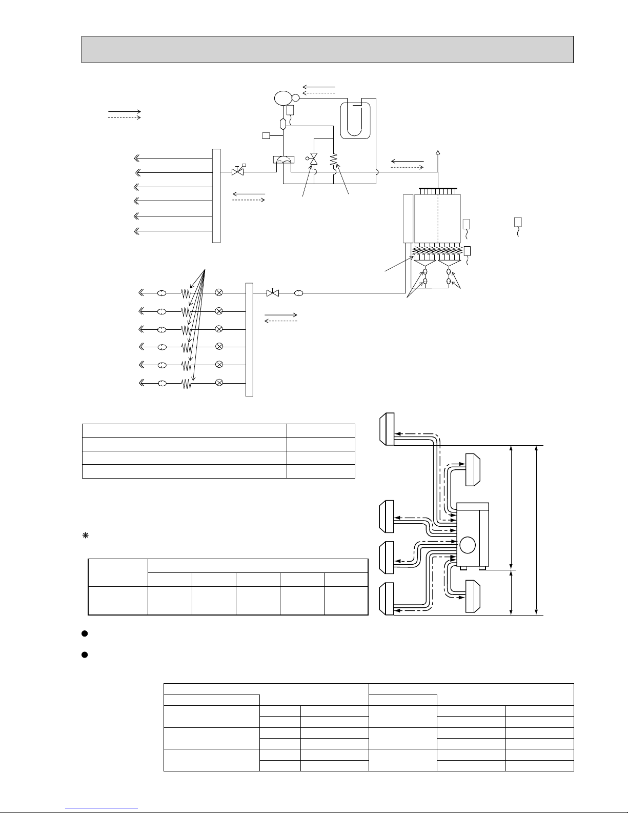
75
Strainer
#100
Power
receiver
LEV A
LEV B
LEV C
Oil separator
Compressor
Defrost
thermistor
RT61
Distributor
Muffler
4-way valve
LEV E
Indoor unit
C
Indoor unit
B
Indoor unit
A
Indoor unit
A
Indoor unit
B
Indoor unit
C
Capillary tube
Capillary tube
Capillary tube
Capillary tube
Capillary tube
Discharge
temperature
thermistor RT62
Strainer
#100
Strainer
#100
Strainer
#100
R.V. coil
OFF
ON
Refrigerant flow in cooling
Refrigerant flow in heating
Ambient
temperature
thermistor
RT65
Outdoor heat
exchanger
temperature
thermistor
RT68
FAN- OUT
HEX-OUT
Strainer
#100
Stop valve with
service port
Stop valve
High-pressure switch
UNIT: mm
MXZ-3D68VA
MAX REFRIGERANT PIPING LENGTH
a
b
c
Outdoor
unit
Indoor
units
15 m
10 m
15 m
Max.
Height
difference
Piping length each indoor unit (a, b, c) 25 m
Total piping length (a+b+c) 60 m
Bending point for each unit 25
Total bending point 60
It is irrelevant which unit is higher.
ADDITIONAL REFRIGERANT CHARGE
Outdoor unit
precharged
(g)
Refrigerant piping length (one way, 3 unit total)
40 m 50 m 60 m
2,700 0 200 400
Calculation : Xg = 20 g/m x (Refrigerant piping length (m) - 40)
UNIT: mm (inch)
Outdoor unit union diameter
For
Indoor unit A
Liquid 6.35(1/4)
Gas 9.52(3/8)
Indoor unit B
Liquid 6.35(1/4)
Gas 9.52(3/8)
Indoor unit C
Liquid 6.35(1/4)
Gas 9.52(3/8)
Refrigerant pipe diameter is different according to indoor unit to be
connected. When using extension pipes, refer to the right table.
When diameter of refrigerant pipe is different from that of outdoor
unit union, use optional Different-diameter pipe.
For further information on Different-diameter pipe, refer to "PARTS
CATALOG".
WHEN CONNECTING TO MFZ-KJ SERIES INDOOR UNIT
MXZ-3D68VA -E2/E3/
ER2/ER3/ET2/ET3
No. of
MFZ-KJ
indoor units
Refrigerant piping length (L)
Maximum amount of
refrigerant
~ 40 m ~ 60 m
None Charge-less (2,700 g) (L-40) x 20 g/m 3,100 g
1 unit 100 g additional charge (2,800 g) 100 g + (L-40) x 20 g/m 3,200 g
2 units 200 g additional charge (2,900 g) 200 g + (L-40) x 20 g/m 3,300 g
3 units 300 g additional charge (3,000 g) 300 g + (L-40) x 20 g/m 3,400 g
OBH626H

76
MXZ-4D72VA
Indoor unit
D
Power
receiver
LEV A
LEV B
LEV C
LEV D
Oil separator
Compressor
Muffler
4-way valve
LEV E
Indoor unit
C
Indoor unit
B
Indoor unit
A
Indoor unit
A
Indoor unit
B
Indoor unit
C
Indoor unit
D
Capillary tube
Capillary tube
Discharge
temperature
thermistor RT62
Strainer
#100
Strainer
#100
Strainer
#100
Strainer
#100
Strainer
#100
R.V. coil
OFF
ON
Refrigerant flow in cooling
Refrigerant flow in heating
Distributor
HEX-OUT
Outdoor heat
exchanger
temperature
thermistor
RT68
Defrost
thermistor
RT61
Capillary tube
Ambient
temperature
thermistor
RT65
FAN- OUT
Strainer
#100
Stop valve with
service port
Stop valve
High-pressure
switch
UNIT: mm
a
b
c
d
Outdoor
unit
Indoor
units
15 m
10 m
15 m
Max.
Height
difference
UNIT: mm (inch)
Outdoor unit union diameter
For
Indoor unit A
Liquid 6.35(1/4)
Gas 12.7(1/2)
Indoor unit B
Liquid 6.35(1/4)
Gas 9.52(3/8)
Indoor unit C
Liquid 6.35(1/4)
Gas 9.52(3/8)
Indoor unit D
Liquid 6.35(1/4)
Gas 9.52(3/8)
Refrigerant pipe diameter is different according to indoor unit to be
connected. When using extension pipes, refer to the right table.
When diameter of refrigerant pipe is different from that of outdoor
unit union, use optional Different-diameter pipe.
For further information on Different-diameter pipe, refer to "PARTS
CATALOG".
MAX REFRIGERANT PIPING LENGTH
Piping length each indoor unit (a, b, c, d) 25 m
Total piping length (a+b+c+d)
60 m
Bending point for each unit 25
Total bending point 60
It is irrelevant which unit is higher.
ADDITIONAL REFRIGERANT CHARGE
Outdoor unit
precharged
(g)
Refrigerant piping length (one way, 4 unit total)
40 m 50 m 60 m
2,700 0 200 400
Calculation : Xg = 20 g/m x (Refrigerant piping length (m) - 40)
WHEN CONNECTING TO MFZ-KJ SERIES INDOOR UNIT
MXZ-4D72VA -E2/E3/
ER2/ER3/ET2/ET3
No. of
MFZ-KJ
indoor units
Refrigerant piping length (L)
Maximum amount of
refrigerant
~ 40 m ~ 60 m
None Charge-less (2,700 g) (L-40) x 20 g/m 3,100 g
1 unit 100 g additional charge (2,800 g) 100 g + (L-40) x 20 g/m 3,200 g
2 units 200 g additional charge (2,900 g) 200 g + (L-40) x 20 g/m 3,300 g
3 units 300 g additional charge (3,000 g) 300 g + (L-40) x 20 g/m 3,400 g
4 units 400 g additional charge (3,100 g) 400 g + (L-40) x 20 g/m 3,500 g
OBH626H

77
a
b
c
d
Outdoor
unit
Indoor
units
15 m
15 m
10 m
Refrigerant piping length (one way, 4 unit total)
Calculation : Xg = 20 g/m x (Refrigerant piping length (m) - 40)
Max.
Height
difference
Outdoor unit
precharged
(g)
50 m
200
40 m
0
3,500
60 m
400
70 m
600
Indoor unit
D
Stop valve
(with service port)
Stop valve
Power
receiver
LEV A
LEV B
LEV C
LEV D
Oil separator
Compressor
Muffler
4-way valve
LEV F
Indoor unit
C
Indoor unit
B
Indoor unit
A
Indoor unit
A
Indoor unit
B
Indoor unit
C
Indoor unit
D
Capillary tube
Capillary tube
Discharge
temperature
thermistor RT62
High-pressure
switch
Strainer
#100
Strainer
#100
Strainer
#100
Strainer
#100
Strainer
#100
R.V. coil
OFF
ON
Refrigerant flow in cooling
Refrigerant flow in heating
Strainer
#100
Distributor
Outdoor
heat
exchanger
Capillary tube
Defrost
thermistor
RT61
Outdoor heat
exchanger
temperature
thermistor
RT68
Ambient
temperature
thermistor
RT65
HEX-OUT
FAN- OUT
MXZ-4D83VA
UNIT: mm
Refrigerant pipe diameter is different according to indoor unit to be connected. When using extension pipes, refer to the
tables below.
When diameter of refrigerant pipe is different from that of outdoor unit union, use optional Different-diameter pipe.
For further information on Different-diameter pipe, refer to "PARTS CATALOG".
UNIT: mm (inch)
Piping length each indoor unit (a, b, c, d) 25 m
Total piping length (a+b+c+d) 70 m
Bending point for each unit 25
Total bending point 70
MAX REFRIGERANT PIPING LENGTH
Outdoor unit union diameter
For
Indoor unit A
Liquid 6.35(1/4)
Gas 12.7(1/2)
Indoor unit B
Liquid 6.35(1/4)
Gas 9.52(3/8)
Indoor unit C
Liquid 6.35(1/4)
Gas 9.52(3/8)
Indoor unit D
Liquid 6.35(1/4)
Gas 9.52(3/8)
It is irrelevant which unit is higher.
ADDITIONAL REFRIGERANT CHARGE
OBH626H

78
a
b
c
d
Outdoor
unit
Indoor
units
15 m
10 m
15 m
Refrigerant piping length (one way, 5 unit total)
Calculation : Xg = 20 g/m x (Refrigerant piping length (m) - 40)
e
Max.
Height
difference
Outdoor unit
precharged
(g)
50 m
200
40 m
0
4,000
60 m
400
70 m
600
80 m
800
Indoor unit
E
Stop valve
(with service port)
Stop valve
Power
receiver
LEV A
LEV B
LEV C
LEV D
Oil separator
Compressor
Muffler
4-way valve
LEV F
Indoor unit
D
Indoor unit
C
Indoor unit
B
Indoor unit
A
Indoor unit
B
Indoor unit
C
Indoor unit
D
Indoor unit
A
Capillary tube
Capillary tube
Discharge
temperature
thermistor RT62
Strainer
#100
Strainer
#100
Strainer
#100
Strainer
#100
Strainer
#100
LEV E
Indoor unit
E
Strainer
#100
R.V. coil
OFF
ON
Refrigerant flow in cooling
Refrigerant flow in heating
Strainer
#100
Distributor
Outdoor
heat
exchanger
Capillary tube
Defrost
thermistor
RT61
Outdoor heat
exchanger
temperature
thermistor
RT68
Ambient
temperature
thermistor
RT65
High-pressure
switch
HEX-OUT
FAN- OUT
MXZ-5D102VA
UNIT: mm
Refrigerant pipe diameter is different according to indoor unit to be connected. When using extension pipes, refer to the
tables below.
When diameter of refrigerant pipe is different from that of outdoor unit union, use optional Different-diameter pipe.
For further information on Different-diameter pipe, refer to "PARTS CATALOG".
UNIT: mm (inch)
Piping length each indoor unit (a, b, c, d, e) 25 m
Total piping length (a+b+c+d+e) 80 m
Bending point for each unit 25
Total bending point 80
MAX REFRIGERANT PIPING LENGTH
Outdoor unit union diameter
For
Indoor unit A
Liquid 6.35(1/4)
Gas 12.7(1/2)
Indoor unit B
Liquid 6.35(1/4)
Gas 9.52(3/8)
Indoor unit C
Liquid 6.35(1/4)
Gas 9.52(3/8)
Indoor unit D
Liquid 6.35(1/4)
Gas 9.52(3/8)
Indoor unit E
Liquid 6.35(1/4)
Gas 9.52(3/8)
It is irrelevant which unit is higher.
ADDITIONAL REFRIGERANT CHARGE
OBH626H
79
R.V.coil
OFF Refrigerant flow in heating
ON Refrigerant flow in cooling
Compressor
Oil separator
High pressure switch
Ø6.35
Ø6.35
Ø9.52
Ø12.7
Indoor unit A
Accumulator
Ø6.35
LEV A
Ø9.52
2-way
solenoid valve
Distributor
Strainer #100
Union
Union
Header(Gas)
Stop valve
Strainer
Strainer
#50
Strainer
#50
#100
Header(Evaporator)
Charge pipe
Capillary tube
Capillary tube
Ø2.5 x Ø0.6 x 1000
Ø4.0 x Ø2.8 x 100
Ø6.35
Ø6.35
Ø9.52
Ø9.52
Compressor shell
temperature
thermistor RT62
Outdoor
heat exchanger
temperature
thermistor
RT68
Ambient
temperature
thermistor
RT65
Defrost
temperature
thermistor
RT61
Capillary tube
Ø4.0 x Ø2.8 x 100
Outdoor
heat exchanger
4-way valve
Stop valve
(with service port)
Indoor unit B
Indoor unit C
Indoor unit E
Ø9.52
Indoor unit D
Indoor unit F
Indoor unit A
Indoor unit B
Indoor unit C
Indoor unit D
Indoor unit E
Strainer #100
Strainer #100
Strainer #100
Strainer #100 LEV B
LEV E
Ø6.35
Indoor unit F
Strainer #100
LEV F
LEV D
LEV C
a
b
c
d
Outdoor
unit
Indoor
units
15 m
10 m
15 m
Refrigerant piping length (one way, 5 unit total)
Calculation : Xg = 20 g/m x (Refrigerant piping length (m) - 30)
e
f
Max.
Height
difference
Outdoor unit
precharged
(g)
50 m
400
40 m
200
4,000
60 m
600
70 m
800
80 m
1000
MXZ-6D122VA
UNIT: mm
Refrigerant pipe diameter is different according to indoor unit to be connected. When using extension pipes, refer to the
tables below.
When diameter of refrigerant pipe is different from that of outdoor unit union, use optional Different-diameter pipe.
For further information on Different-diameter pipe, refer to "PARTS CATALOG".
Piping length each indoor unit (a, b, c, d, e) 25 m
Total piping length (a+b+c+d+e) 80 m
Bending point for each unit 25
Total bending point 80
MAX REFRIGERANT PIPING LENGTH
UNIT: mm (inch)
Outdoor unit union diameter Outdoor unit union diameter
For For
Indoor unit A
Liquid 6.35(1/4)
Indoor unit D
Liquid 6.35(1/4)
Gas 12.7(1/2) Gas 9.52(3/8)
Indoor unit B
Liquid 6.35(1/4)
Indoor unit E
Liquid 6.35(1/4)
Gas 9.52(3/8) Gas 9.52(3/8)
Indoor unit C
Liquid 6.35(1/4)
Indoor unit F
Liquid 6.35(1/4)
Gas 9.52(3/8) Gas 9.52(3/8)
It is irrelevant which unit is higher.
ADDITIONAL REFRIGERANT CHARGE
OBH626H

80
When relocating or disposing of the air conditioner, pump down the system following the procedure below so that no refrigerant is released into the atmosphere.
1) Turn off the breaker.
2) Connect the gauge manifold valve to the service port of the stop valve on the gas pipe side of the outdoor unit.
3) Fully close the stop valve on the liquid pipe side of the outdoor unit.
4) Turn on the breaker.
5) Start the emergency COOL operation on all the indoor units.
6) When the pressure gauge shows 0.05 to 0 MPa [Gauge] (approximately 0.5 to 0 kgf/cm²), fully close the stop valve
on the gas pipe side of the outdoor unit and stop the operation. (Refer to the indoor unit installation manual about the
method for stopping the operation.)
* If too much refrigerant has been added to the air conditioner system, the pressure may not drop to
0.05 to 0 MPa [Gauge]
(approximately 0.5 to 0 kgf/cm²)
, or the protection function may operate due to the pressure increase in the high-pressure refrigerant circuit. If this occurs, use a refrigerant collecting device to collect all of the refrigerant in the system, and
then recharge the system with the correct amount of refrigerant after the indoor and outdoor units have been relocated.
7) Turn off the breaker. Remove the pressure gauge and the refrigerant piping.
When pumping down the refrigerant, stop the compressor before disconnecting the refrigerant pipes.
The compressor may burst and cause injury if any foreign substance, such as air, enters the pipes.
WARNING
PUMPING DOWN
OBH626H

115
ACTUATOR CONTROL
9
Relation between main sensor and actuator
Sensor Purpose
Actuator
Compressor LEV
Outdoor
fan motor
R.V. coil
Defrost
heater
1
Discharge temperature thermistor Protection
Indoor coil temperature thermistor
Cooling: Coil frost prevention
Heating: High pressure protection
Defrost thermistor Heating: Defrosting
Fin temperature thermistor Protection
Ambient temperature thermistor
Control/Protection
Heating: Defrosting (Heater)
Outdoor heat exchanger
temperature thermistor
Cooling: Control/Protection
Capacity code Control
1 MXZ-2D53VAH only.
MXZ-2D33VA MXZ-2D40VA MXZ-2D42VA MXZ-2D53VA MXZ-2D53VAH
MXZ-3D54VA MXZ-3D54VA2 MXZ-3D68VA MXZ-4D72VA MXZ-4D83VA MXZ-5D102VA
MXZ-6D122VA
OBH626H
116
Outdoor display P.C. board
SW1 SW2
ON
123456
ON
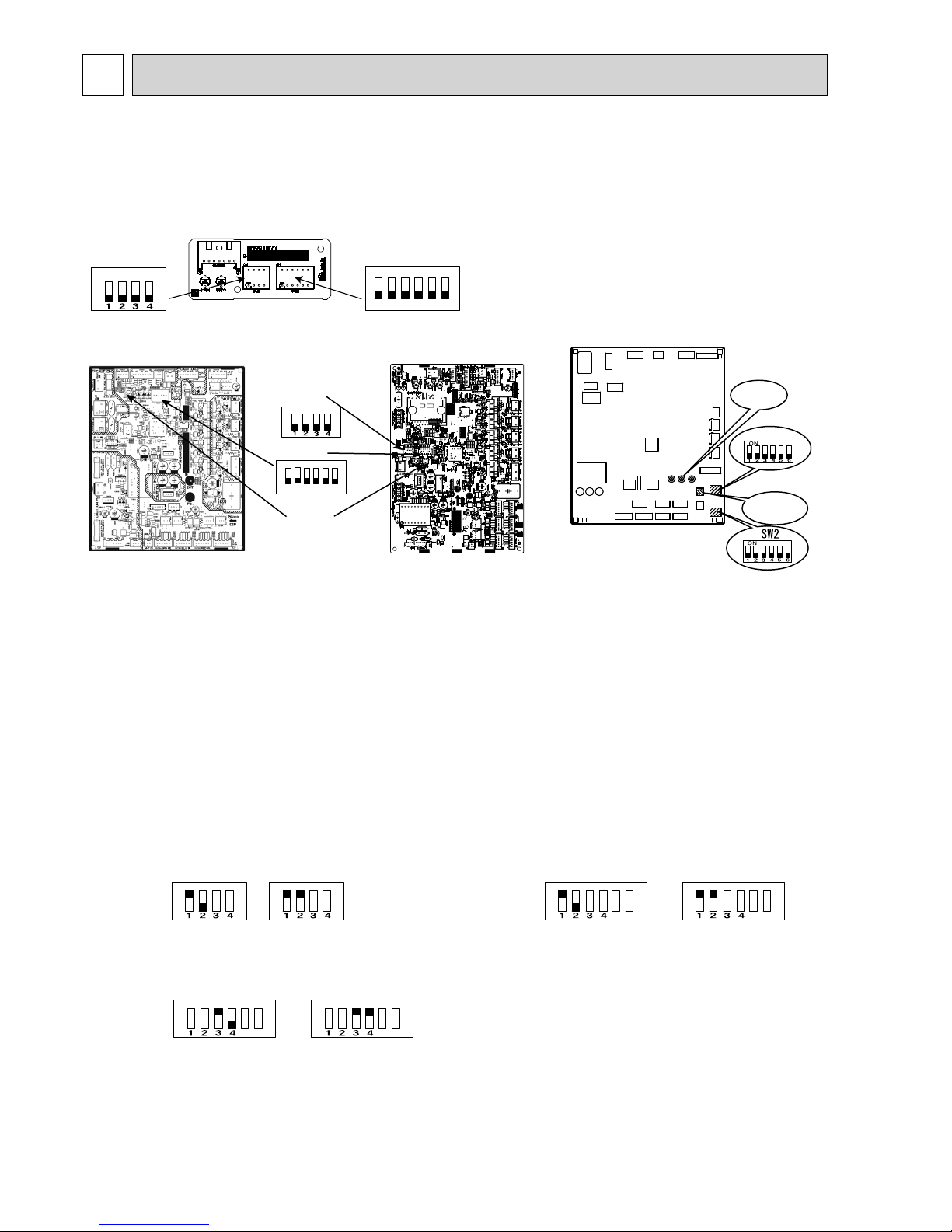
SERVICE FUNCTIONS
10
10-1. THE POSITION OF SWITCH
MXZ-2D33VA MXZ-2D40VA MXZ-2D42VA MXZ-2D53VA MXZ-2D53VAH
MXZ-3D54VA MXZ-3D54VA2 MXZ-3D68VA MXZ-4D72VA MXZ-4D83VA MXZ-5D102VA
MXZ-6D122VA
MXZ-2D33VA MXZ-2D40VA MXZ-2D42VA MXZ-2D53VA MXZ-2D53VAH
ON
SW1
ON
SW1
Cool/Dry Heat
With this function, you can lock the operation mode of the outdoor unit.
Once the operation mode is locked to either COOL/DRY mode or HEAT mode, the air conditioner
operates in that mode only.
Default setting is required to activate this function.
Please explain this function to your customers and ask them whether they want to use it.
[How to lock the operation mode]
(1) Turn OFF the power supply and make sure that the LED goes off.
(2) Set SW1 or SW2 as shown in the figure below.
(3) Turn ON the power supply.
10-2. LOCKING THE OPERATION MODE OF THE AIR CONDITIONER (COOL, DRY, HEAT)
MXZ-2D33VA/2D40VA/2D42VA/2D53VA/2D53VAH
SW1 on the outdoor display P.C. board
MXZ-4D83VA/5D102VA
SW1 on the outdoor control P.C. board
MXZ-6D122VA
SW1 on the outdoor control P.C. board
ON
5
6
SW2
ON
5
6
SW2
Cool/Dry Heat
ON
5
6
SW1
ON
5
6
SW1
Cool/Dry Heat
MXZ-3D54VA/3D54VA2/3D68VA/4D72VA
SW2 on the outdoor control P.C. board
MXZ-3D54/3D68/4D72V A
MXZ-3D54V A2
Oudoor control P .C. board
ON
ON
SW2
SW871
SW1
123456
MXZ-4D83/5D102V A
Oudoor control P.C. board
Outdoor control P .C. board
SW871
SW1
LED
MXZ-6D122VA
OBH626H

117
10-3. LOWERING THE OPERATING NOISE OF THE OUTDOOR UNIT
With this function, you can lower the operating noise of the outdoor unit when the operation load is small,
for example, during night time in COOL mode.
However, note that the cooling and heating capacity can also be lowered if this function is activated.
Default setting is required to activate this function.
Please explain this function to your customers and ask them whether they want to use it.
[How to lower the operating noise]
(1) Turn OFF the power supply and make sure that the LED goes off.
(2) Set the "3" Switch of SW1 to ON to enable this function. (MXZ-2D33VA/2D40VA/2D42VA/2D53VA/2D53VAH/
4D83VA/5D102VA)
Set the "3" Switch of SW2 to ON to enable this function. (MXZ-3D54VA/3D54VA2/3D68VA/4D72VA)
Set the "5" Switch of SW1 to ON to enable this function. (MXZ-6D122VA)
(3) Turn ON the power supply.
ON
SW1
MXZ-2D33VA/2D40VA/2D42VA/2D53VA/2D53VAH
SW1 on the outdoor display P.C. board
MXZ-4D83VA/5D102VA
SW1 on the outdoor control P.C. board
MXZ-6D122VA
SW1 on the outdoor control P.C. board
ON
5
6
SW2
ON
5
6
SW1
MXZ-3D54VA/3D54VA2/3D68VA/4D72VA
SW2 on the outdoor control P.C. board
10-4. AUTOMATIC LINE CORRECTING
This outdoor unit has an automatic line correcting function which automatically detects and corrects improper wiring or piping.
<MXZ-2D33VA/2D40VA/2D42VA/2D53VA/2D53VAH>
Improper wiring or piping can be automatically detected when one indoor unit is operated in COOL mode for 30 minutes.
When improper wiring or piping is detected, wiring lines are corrected (A to B/ B to A) with the software.
NOTE: This function may not work due to the condition or environment of the unit, such as the following:
- gas leak, closed stop valve
- unit failure such as defective LEV
- indoor/outdoor temperature
NOTE: This function does not work when the "2" of SW2 on the outdoor display P.C. board is turned OFF.
SW2
<Correct>
Indoor/outdoor
connecting wire
Terminal
block
Refrigerant pipe
Indoor unit B
Liquid/
Gas pipe
Indoor unit A
Outdoor unit
<Incorrect wiring>
Terminal
block
Indoor unit B
Liquid/
Gas pipe
Indoor unit A
Outdoor unit
<Incorrect piping>
Terminal
block
Indoor unit B
Liquid/
Gas pipe
Indoor unit A
Outdoor unit
B
A
B
A
B
A
B
A
B
A
B
A
MXZ-2D33VA/2D40VA/2D42VA/2D53VA/
MXZ-2D53VAH
SW2 on the outdoor display P.C. board
OBH626H

118
The record of automatic line correcting can be checked in the following way:
(1) Turn OFF the power supply and make sure that the LED goes off.
(2) Turn ON the "3" of SW2 on the outdoor display P.C. board.
(3) Turn ON the power supply.
(4) Check the correction state with the LED lamps on the outdoor display P.C. board.
(5) Turn OFF the power supply and make sure that the LED goes off.
(6) Turn OFF the "3" of SW2 on the outdoor display P.C. board.
(7) Turn ON the power supply.
Number of blinks
Wiring line
LED1 (Red) LED2 (Yellow)
Once Once Not corrected
3 times 3 times Corrected
SW2
<MXZ-3D54VA/3D54VA2/3D68VA/4D72VA/4D83VA/5D102VA>
Improper wiring or piping can be automatically detected by pressing the piping/wiring correction switch (SW871) on the
outdoor control P.C. board.
When improper wiring or piping is detected, wiring lines are corrected.
This will be completed in about 10 to 20 minutes.
[How to activate this function]
1. Check that outside temperature is above 0ºC.
(This function does not work when outside temperature is not above 0ºC. )
2. Check that the stop valves of the liquid pipe and gas pipe are open.
3. Check that the wiring between indoor and outdoor unit is correct.
(If the wiring is not correct, this function does not work.)
4. Turn ON the power supply and wait at least 1 minute.
5. Press the piping/wiring correction switch (SW871) on the outdoor P.C. board.
Do not touch energized parts.
LED indication during detection:
LED1 (Red) LED2 (Yellow) LED3 (Green)
Lighted Lighted Once
LED indication after detection:
LED1 (Red) LED2 (Yellow) LED3 (Green) Indication
Lighted Not lighted Lighted Completed (Problem corrected/Normal)
Once Once Once Not completed (Detection failed)
Other indications
Refer to "SAFETY PRECAUTIONS WHEN LED
FLASHES" located behind the service panel.
Make sure that the valves are open and the pipes are not collapsed or clogged.
6. Press the switch to cancel.
LED indication after cancel:
LED1 (Red) LED2 (Yellow) LED3 (Green)
Lighted Lighted Not lighted
NOTE: Indoor unit cannot be operated while this function is activated.
When this function is activated while indoor unit is operating, the operation will be stopped.
Operate indoor unit after the automatic line correcting is finished.
Pressing the switch during detection cancels this function.
The record of automatic line correcting can be checked in the following way:
Press the switch for more than 5 seconds
LED will show the record of automatic correcting for about 30 seconds as shown in the table below:
Number of blinks
Wiring line
LED1 (Red) LED2 (Yellow) LED3 (Green)
Once Once Lighted Not corrected
3 times 3 times Lighted Corrected
NOTE: Activate this function to check the correct wiring after replacing the outdoor P.C. board.
(Previous records are deleted when the outdoor control P.C. board is replaced.)
The record cannot be shown if automatic line correcting is not cancelled (Refer to "How to activate this function").
MXZ-2D33VA/2D40VA/2D42VA/2D53VA/2D53VAH
SW2 on the outdoor display P.C. board
OBH626H

119
<MXZ-6D122VA>
Improper wiring or piping can be automatically detected by pressing the piping/wiring correction switch (SW871).
When improper wiring or piping is detected, wiring lines are corrected.
This will be completed in about 10 to 20 minutes.
[How to activate this function]
1. Check that outside temperature is above 0˚C.
(This function does not work when outside temperature is not above 0˚C.)
2. Check that the stop valves of the liquid pipe and gas pipe are open.
3. Check that the wiring between indoor and outdoor unit is correct.
(If the wiring is not correct, this function does not work.)
4. Turn ON the power supply and wait at least 1 minute.
5. Press the piping/wiring correction switch (SW871) on the outdoor control P.C. board.
Do not touch energized parts.
LED indication during detection:
LED1 (Red) LED2 (Yellow) LED3 (Green)
Lighted Lighted Once
LED indication after detection:
LED1 (Red) LED2 (Yellow) LED3 (Green) Indication
Lighted Not lighted Lighted Completed (Problem corrected/ normal)
Once Once Once Not completed (Detection failed)
Other indications
Refer to "SAFETY PRECAUTIONS WHEN LED
FLASHES" located behind the service panel.
Make sure that the valves are open and the pipes are not collapsed or clogged.
6. Press the switch to cancel.
LED indication after cancel:
LED1 (Red) LED2 (Yellow) LED3 (Green)
Lighted Lighted Not lighted
NOTE: Indoor unit cannot be operated while this function is activated.
When this function is activated while indoor unit is operating, the operation will be stopped.
Operate indoor unit after the auto line correcting is finished.
Pressing the switch during detection cancels this function.
The record of auto line correcting can be confirmed in the following way:
Press the switch for more than 5 seconds.
LED will show the record of auto correcting for about 30 seconds as shown in the table below:
Number of blinks
Wiring line
LED1 (Red) LED2 (Yellow) LED3 (Green)
Once Once Lighted Not corrected
3 times 3 times Lighted Corrected
NOTE: Activate this function to check the correct wiring after replacing the outdoor P.C. board.
(Previous records are deleted when the outdoor control P.C. board is replaced.)
The record cannot be shown if automatic line correcting is not cancelled (Refer to "How to activate this function").
OBH626H

120
10-5. PRE-HEAT CONTROL
If moisture gets into the refrigerant cycle, or when refrigerant is liquefied and collected in the compressor,
it may interfere the start-up of the compressor. To improve start-up condition, the compressor is energized even while it
is not operating to generate heat at the winding.
The compressor uses about 50 W when pre-heat control is turned ON. Pre-heat control is OFF(MXZ-2D33VA/2D40VA/2
D42VA/2D53VA/2D53VAH) / ON (MXZ-3D54VA/3D54VA2/3D68VA/4D72VA/4D83VA/5D102VA/6D122VA) at the default
setting.
[How to activate pre-heat control]
MXZ-2D33VA/2D40VA/2D42VA/2D53VA/2D53VAH/3D54VA/3D54VA2/3D68VA/4D72VA/4D83VA/5D102VA
(1) Turn OFF the power supply and make sure that the LED goes off.
(2) Set the “4” of SW2 as shown figure below to ON to activate pre-heat control function.
(3) Turn ON the power supply.
SW2
SW2
MXZ-2D33VA/2D40VA/2D42VA/2D53VA/2D53VAH
SW2 on the outdoor display P.C. board
MXZ-6D122VA
SW2 on the outdoor control P.C. board
MXZ-3D54VA/3D54VA2/3D68VA/4D72VA
MXZ-4D83VA/5D102VA
SW2 on the outdoor control P.C. board
MXZ-6D122VA
(1) Turn OFF the power supply for the air conditioner before making the setting.
(2) Set the "4" of SW2 as shown figure below to OFF to activate pre-heat control function.
(3) Turn ON the power supply for the air conditioner.
NOTE: Pre-heat control will be turned OFF when the power supply is turned OFF.
OBH626H

121
10-6. CHANGING THE AMPERE LIMIT
With this function, you can change the current that flows in the outdoor unit.
NOTE: Use this function only when the amount of current exceeds the allowed value.
[How to change the ampere limit]
MXZ-4D83VA/5D102VA
(1) Turn OFF the power supply and make sure that the LED goes off.
(2) Set SW2 as shown in the table below.
(3) Turn ON the power supply.
SW2 on the outdoor control P.C. board
SW2
MXZ-4D83VA/5D102VA
10.5 A
15.5 A
Default setting
Full
MXZ-6D122VA
(1) Be sure to turn off the main power for the air conditioner before making the setting.
(2) Make the setting referring to the table below.
(3) Turn ON the power supply.
SW2 on the outdoor control P.C. board
SW2
MXZ-6D122VA
20 A
Default setting
Full
OBH626H

122
11
TROUBLESHOOTING
3. Troubleshooting procedure
1)
Check if the OPERATION INDICATOR lamp on the indoor unit is fl ashing on and off to indicate an abnormality. To
make sure, check how many times the OPERATION INDICATOR lamp is fl ashing on and off before starting service
work
.
2) Before servicing, check that the connector and terminal are connected properly.
3) When the P.C. board seems to be defective, check the copper foil pattern for disconnection and the components for
bursting and discoloration.
4) Refer to 11-2, 11-3 and 11-4.
11-1. CAUTIONS ON TROUBLESHOOTING
1. Before troubleshooting, check the following:
1) Check the power supply voltage.
2) Check the indoor/outdoor connecting wire for miswiring.
2. Take care of the following during servicing
1) Before servicing the air conditioner, be sure to turn OFF the unit fi rst with the remote controller, and after confi rming
the horizontal vane is closed, turn OFF the power supply and/or disconnect the power plug.
2) Be sure to turn OFF the power supply before removing the front panel, the cabinet, the top panel, and the P.C. board.
3) When removing the electrical parts, be careful of the residual voltage of smoothing capacitor.
4) When removing the P.C. board, hold the edge of the board with care NOT to apply stress on the components.
5) When connecting or disconnecting the connectors, hold the connector housing. DO NOT pull the lead wires.
11-2. FAILURE MODE RECALL FUNCTION
This air conditioner can memorize the abnormal condition which has occurred once.
Even though LED indication listed on the troubleshooting check table (11-4.) disappears, the memorized failure details
can be recalled.
1. Flow chart of failure mode recall function for the indoor/outdoor unit
Refer to the service manual of indoor unit.
MXZ-2D33VA MXZ-2D40VA MXZ-2D42VA MXZ-2D53VA MXZ-2D53VAH
MXZ-3D54VA MXZ-3D54VA2 MXZ-3D68VA MXZ-4D72VA MXZ-4D83VA MXZ-5D102VA
MXZ-6D122VA
Lead wiring
Connector housing
<Incorrect>
<Correct>
OBH626H

123
2. Flow chart of the detailed outdoor unit failure mode recall function
2.Blinking pattern when outdoor unit is abnormal:
ON
OFF
No beep
Beeps
Repeated cycle
2.5-second OFF 3-second ON
Blinking at 0.5second interval
No beep Beeps
Repeated cycle
2.5-second OFF 3-second ON
Blinking at 0.5-
second interval
Repeated cycle
Does the OPERATION INDICATOR lamp on the
indoor unit blink at the interval of 0.5 seconds?
Blinks: The outdoor unit is abnormal. Beep is emit-
ted at the same timing as the blinking of the
OPERATION INDICATOR lamp.
2
Yes
(Blinks
)
No
(OFF)
The outdoor unit might be abnormal.
Check if outdoor unit is abnormal according to the following procedures.
Operational procedure
With the remote controller headed towards the indoor unit, press the
TEMPERATURE buttons to adjust the set temperature to 25°C.
1
1 Regardless of normal or abnormal condition, 2 short
beeps are emitted as the signal is received.
The outdoor unit is abnormal.
Check the blinking pattern, and identify the abnormal point by referring to
the outdoor unit failure mode table (11-2.3.).
Make sure to check at least 2 consecutive blinking cycles.
2
Repair the failure parts.
The outdoor unit is normal.
Release the failure mode recall function. 3
NOTE: 1. Make sure to release the failure mode recall function after it is set up, otherwise the unit cannot operate properly.
2. If the abnormal condition is not deleted from the memory, the last abnormal condition is kept memorized.
Delete the memorized abnormal condition. 3
Release the failure mode recall function. 3
3 Refer to the service manual of indoor unit.
Release the failure mode recall function. 3
Make sure that the remote controller is set to the failure mode recall function.
3
OBH626H

124
3. Outdoor unit failure mode table
MXZ-2D
Upper or
left lamp of
OPERATION
INDICATOR
lamp (Indoor
unit)
Abnormal point
(Failure mode/protection)
LED indication
(Outdoor P.C. board)
Condition Remedy
Indoor/
outdoor
unit failure
mode
recall
function
LED 1 LED 2
OFF None (Normal)
Not lighted Not lighted
———
2-time fl ash Outdoor power system Lighted Lighted Overcurrent protection cut-out operates
3 consecutive times within 1 minute after
the compressor gets started.
Compressor protection cut-out
operates 24 consecutive times within
10 seconds after the compressor gets
started.
• Check the compressor connecting
wire.
• Refer to 11-6.
"How to check
inverter/compressor".
• Check the stop valve.
○
3-time fl ash Discharge temperature
thermistor
Lighted Once Thermistor shorts or opens during
compressor running.
• Refer to 11-6. "Check of outdoor thermistors".
○
Defrost thermistor Lighted Once
○
Ambient temperature
thermistor
Lighted Twice
○
Fin temperature thermistor Lighted 3 times
○
P.C. board temperature
thermistor
Lighted 4 times • Replace the inverter P.C. board.
○
Outdoor heat exchanger
temperature thermistor
Lighted 9 times • Refer to 11-6. "Check of out-
door thermistors".
○
4-time fl ash Overcurrent Once Not
lighted
The overcurrent fl ows into intelligent
power module.
• Check the compressor connecting
wire.
• Refer to 11-6.
"How to check
inverter/compressor".
• Check the stop valve.
—
Compressor Twice Not
lighted
The overcurrent fl ows into intelligent
power module within 10 seconds after
the compressor gets started.
( The compressor gets restarted in
15 seconds.)
• Check the compressor connecting
wire.
• Refer to 11-6.
"How to check
inverter/compressor".
—
9 times Not
lighted
Waveform of compressor current is distorted.
—
5-time fl ash Discharge temperature Lighted Lighted Discharge temperature exceeds 116 ºC
during operation.
• Check the refrigerant circuit and
the refrigerant amount.
• Refer to 11-6.
"Check of LEV".
—
6-time fl ash High pressure Lighted Lighted The outdoor heat exchanger temperature
exceeds 70 ºC during cooling or the indoor gas pipe temperature exceeds
70 ºC during heating.
• Check the refrigerant circuit and
the refrigerant amount.
• Check the stop valve.
—
7-time fl ash Fin temperature 3 times Not
lighted
The fi n temperature exceeds 90 ºC
during operation.
•
Check the around outdoor unit.
• Check the outdoor unit air passage.
—
P.C. board temperature 4 times Not
lighted
The P.C. board temperature exceeds
80 ºC during operation.
• Refer to 11-6.
"Check of out-
door fan motor".
—
8-time fl ash Outdoor fan motor Lighted Lighted Failure occurs 3 consecutive times
within 30 seconds after the fan gets
started.
• Refer to 11-6.
"Check of out-
door fan motor".
—
9-time fl ash Nonvolatile memory data Lighted 5 times Nonvolatile memory data cannot be read
properly.
• Replace the inverter P.C. board.
○
Power module 7 times Not
lighted
The output of the power module that
drove the compressor was shorted or
the winding of the compressor was
shorted.
• Refer to 11-6. "How to check
inverter/compressor".
○
10-time fl ash Discharge temperature Lighted Lighted The discharge temperature is kept
under 50 ºC (COOL mode)/40 ºC (HEAT
mode) for more than 40 minutes.
• Check the refrigerant circuit and
the refrigerant amount.
• Refer to 11-6.
"Check of LEV".
—
11-time fl ash Current sensor 8 times Not
lighted
The sensor circuit of current of
compressor shorts or opens during
compressor operate.
• Replace the inverter P.C. board.
○
Bus-bar voltage 6 times Not
lighted
The bus-bar voltage exceeds 430 V or
falls to 50 V or below during compressor operating.
• Check the power supply.
• Replace the inverter P.C. board.
○
14-time fl ash Stop valve Lighted 12 times The current of compressor is power
module is out of order.
• Check the stop valve.
• Check the refrigerant circuit and
the refrigerant amount.
○
17 time fl ash Outdoor refrigerant system
abnormality
Lighted 17 times A closed valve and air trapped in the re-
frigerant circuit are detected based on the
temperature sensed by the indoor and
outdoor thermistors and the current of the
compressor.
•
Check for a gas leak in a connecting
piping etc.
• Check the stop valve.
• Refer to 11-6.
"Check of out-
door refrigerant circuit".
○
NOTE: Blinking patterns of this mode differ from the ones of Troubleshooting check table (11-4).
OBH626H
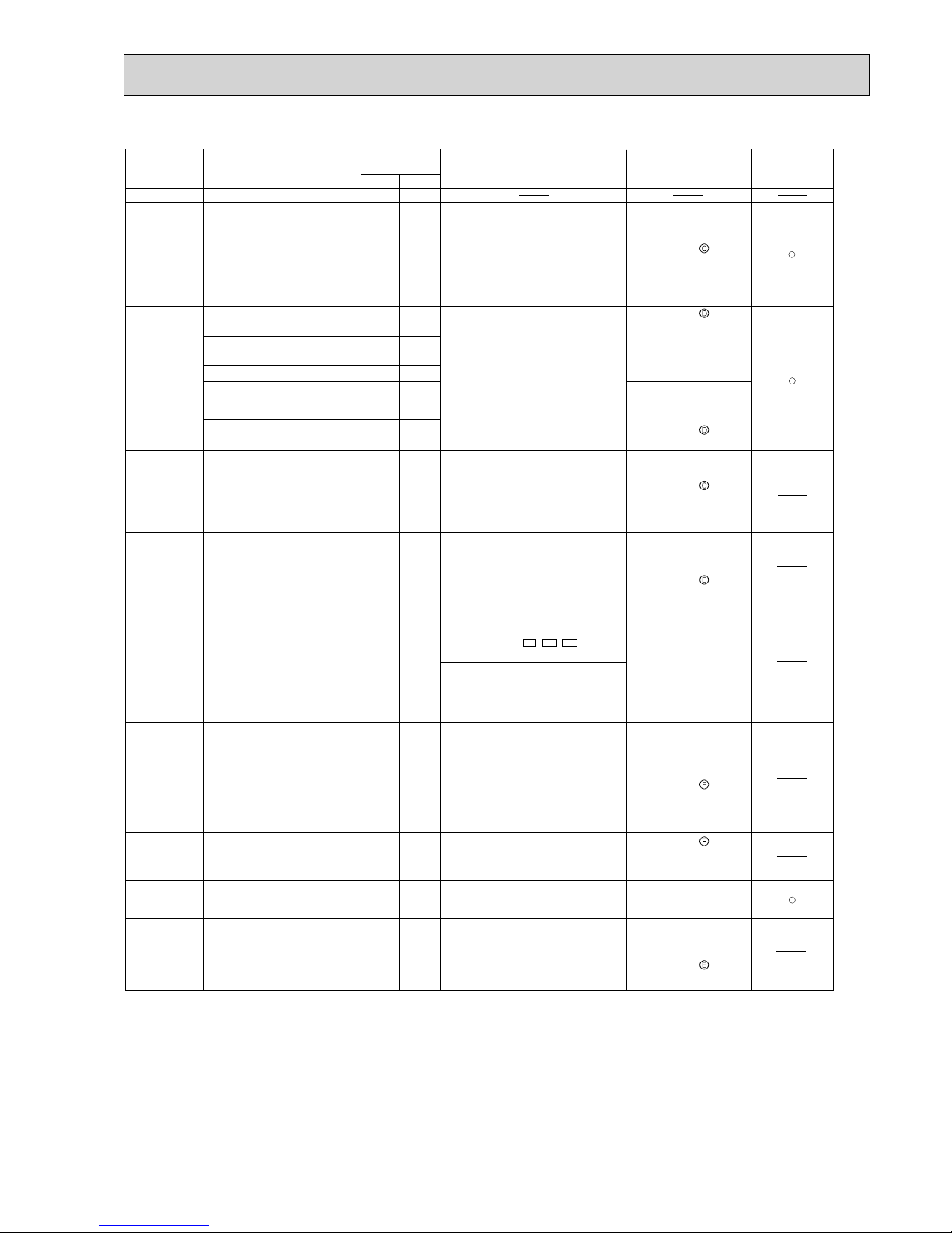
125
The frequency of the compressor is
kept 80Hz or more and the discharge
temperature is kept under
50°C (cooling)/40°C (heating)
for more than 40 minutes.
Abnormal point
(Failure mode/protection)
Condition
Remedy
Indoor/outdoor
unit failure mode
recall function
LED indication
(Outdoor P.C. board)
LED 1LED 2
OFF
2-time flash
3-time flash
4-time flash
5-time flash
6-time flash
7-time flash
8-time flash
Lighted Lighted
Lighted Lighted
Lighted Once
Lighted Once
Lighted Twice
Lighted 3 times
Lighted 4 times
Lighted
9 times
Once
Not lighted
Lighted
Lighted
Lighted
E3 ER3 ET3
Lighted
3 times
Not lighted
4 times
Not lighted
Lighted
Lighted
Lighted
Lighted
Lighted
5 times
9-time flash
10-time flash
Replace the outdoor
control P.C. board.
Replace the outdoor
control P.C. board.
&KHFNWKHUHIULJHUDQW
circuit and the refrigerant
amount.
Refer to 11-6.
"Check
of LEV".
Reconnect compressor
connector.
Refer to 11-6.
"How to
check inverter/
compressor".
Check the stop valve.
&KHFNWKHUHIULJHUDQW
circuit and the refrigerant
amount.
Check the stop valve.
Refer to 11-6.
"Check
of outdoor fan motor".
&KHFNWKHUHIULJHUDQW
circuit and the refrigerant
amount.
Refer to 11-6.
"Check
of LEV".
&KHFNWKHDURXQGRXW
door unit.
&KHFNWKHRXWGRRUXQLW
air passage.
5HIHUWR
"Check
of outdoor fan motor".
&KHFNWKHFRQQHFWLRQ
of the compressor
connecting wire.
5HIHUWR
"How to check
inverter/compressor".
&KHFNWKHVWRSYDOYH
Refer to 11-6.
"Check
of outdoor thermistors".
Refer to 11-6.
"Check
of outdoor thermistors".
Overcurrent protection cut-out operates
3 consecutive times within 1 minute after
the compressor gets started, or converter
protection or bus-bar voltage protection
cut-out operates 3 consecutive times
within 3 minutes after start-up.
Thermistor shorts or opens during
compressor running.
28 A current flows into intelligent power
module.
Discharge temperature exceeds 116°C
during operation.
Compressor can restart if discharge
temperature thermistor reads 100°C or
less 3 minutes later.
High-pressure is detected with the
high-pressure switch (HPS)
during operation.
(MXZ-3D54VA2-
MXZ-3D68/4D72/4D83/5D102VA)
,,
The outdoor heat exchanger
temperature exceeds 70°C during
cooling or the indoor gas pipe
temperature exceeds 70°C during
heating.
The fin temperature exceeds 89°C
during operation.
The P.C. board temperature exceeds
73°C (MXZ-3D54/3D68/4D72VA
MXZ-3D54VA2)/
87°C (MXZ-4D83/5D102VA)
during operation.
Failure occurs 3 consecutive
times within 30 seconds after the
fan gets started.
Nonvolatile memory data cannot be
read properly.
Outdoor power system
Discharge temperature
thermistor
Defrost thermistor
Ambient temperature thermistor
Fin temperature thermistor
P.C. board temperature
thermistor
Overcurrent
Discharge temperature
High pressure
Fin temperature
P.C. board temperature
Outdoor fan motor
Nonvolatile memory data
Discharge temperature
None (Normal)
Upper or left lamp of
OPERATION INDICATOR
lamp (Indoor unit)
Outdoor heat exchanger
temperature thermistor
NOTE: Blinking patterns of this mode differ from the ones of Troubleshooting check table (11-4).
MXZ-3D/4D/5D
OBH626H
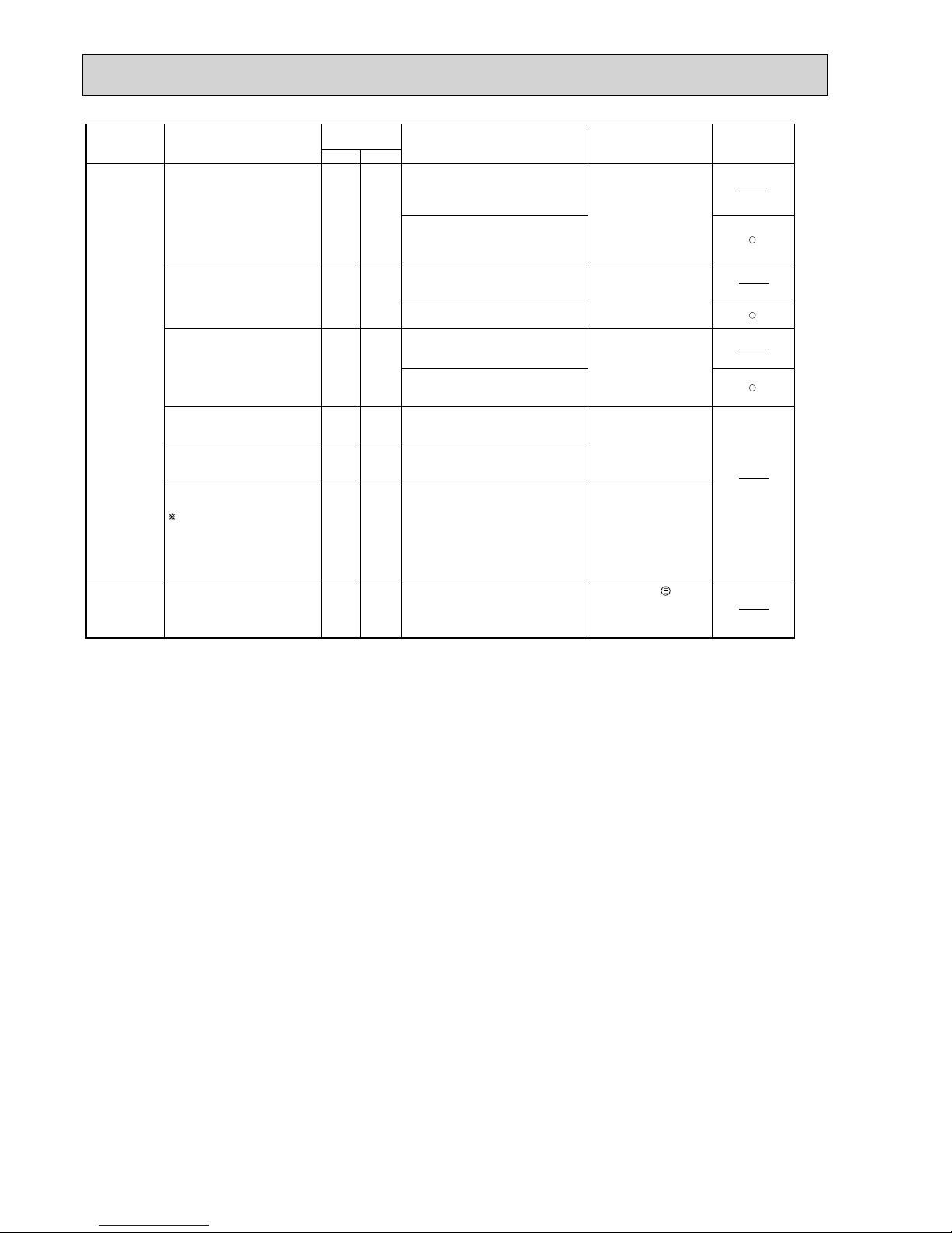
126
11-time flash
15-time flash
Check the connecting
wire between the outdoor
control P.C. board and
the power P.C. board.
Replace the power P.C.
board.
Check the connecting
wire between the control
P.C. board, the noise
filter P.C. board and
the power P.C. board.
Check the voltage of the
power supply.
5HSODFHWKH
power P.C.
board.
Check the voltage of the
power supply.
5HSODFHWKHRXWGRRU
control P.C. board.
Refer to 11-6. "Check
of LEV".
Check the drain pump of
the indoor unit.
The communication between boards
protection cut-out operates 2
consecutive times.
Communication error occurs
between the electronic control P.C.
board and power board for more
than 10 seconds.
Current sensor protection cut-out
operates 2 consecutive times.
A short or open circuit is detected in
the current sensor during compressor
operating.
The protection cut-out of the zero cross
detecting circuit operates 10
consecutive times.
Zero cross signal cannot be detected
while the compressor is operating.
A failure is detected in the operation
of the converter during operation.
The bus-bar voltage exceeds 400 V or
falls to 200 V or below during
compressor operating.
The bus-bar voltage exceeds
400 V (MXZ-3D54/3D68/4D72VA
MXZ-3D54VA2)
430 V (MXZ-4D83/5D102VA)
or falls to 50V or below during
compressor operating.
Communication error
between P.C. boards
Current sensor
Zero cross detecting circuit
Converter
Bus-bar voltage
(1)
Bus-bar voltage
(2)
Even if this protection stop is
performed continuously three
times, it does not mean the
abnormality in outdoor power
system.
LEV and drain pump
Lighted 6 times
Lighted 7 times
5 times Not
lighted
5 times
Not
lighted
5 times
6 times
Not
lighted
Not
lighted
The indoor unit detects an abnormality
in the LEV and drain pump.
Lighted
Lighted
Abnormal point
(Failure mode/protection)
Condition
Remedy
Indoor/outdoor
unit failure mode
recall function
LED indication
(Outdoor P.C. board)
LED 1LED 2
Upper or left lamp of
OPERATION INDICATOR
lamp (Indoor unit)
NOTE: Blinking patterns of this mode differ from the ones of "Troubleshooting check table" (11-4).
OBH626H
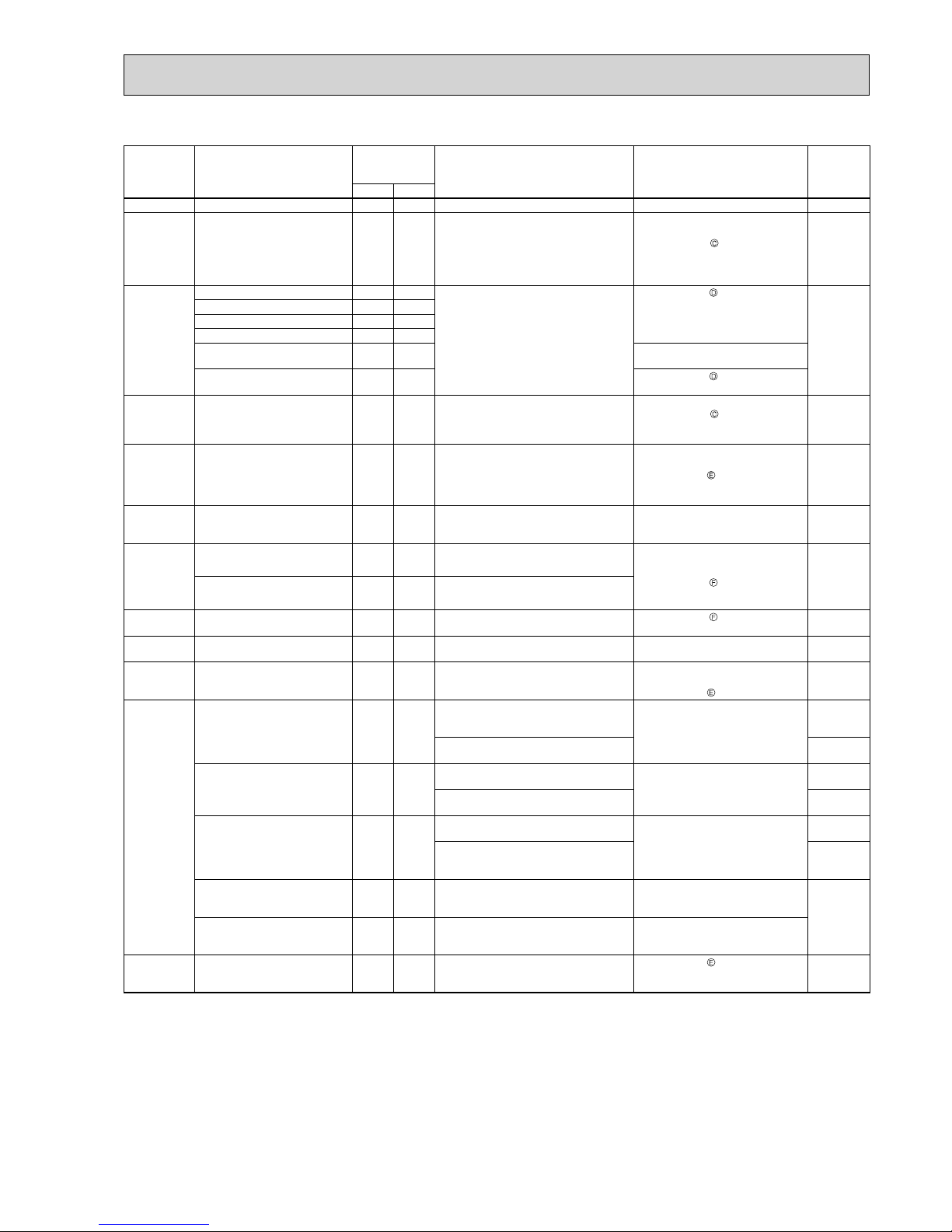
127
The left lamp of
OPERATION IN-
DICATOR lamp
(Indoor unit)
Abnormal point
(Failure mode/protection)
LED indication
(Outdoor P.C.
board)
Condition Remedy
Indoor/
outdoor unit
failure mode
recall function
LED 1 LED 2
OFF None (Normal) Lighted Lighted
2-time fl ash Outdoor power system Lighted Lighted
Overcurrent protection cut-out operates 3 consecutive times within 1 minute after the compressor gets started, or converter protection
cut-out or bus-bar voltage protection cut-out
operates 3 consecutive times within 3 minutes
after start-up.
• Check the compressor connecting
wire.
• Refer to 11-6.
"How to check in-
verter/compressor".
• Check the stop valve.
○
3-time fl ash
Discharge temperature thermistor
Lighted Once
A thermistor shorts or opens during
compressor running.
• Refer to 11-6. "Check of outdoor
thermistors".
○
Defrost thermistor
Lighted Once
Ambient temperature thermistor
Lighted Twice
Fin temperature thermistor
Lighted 3 times
P.C. board temperature thermistor
Lighted 4 times • Replace the outdoor control P.C.
board.
Outdoor heat exchanger temperature thermistor
Lighted 9 times • Refer to 11-6.
"Check of outdoor
thermistors".
4-time fl ash Overcurrent Once Not
lighted
28 A current fl ows into power module.
• Reconnect compressor connector.
• Refer to 11-6.
"How to check in-
verter/compressor".
• Check the stop valve.
—
5-time fl ash Discharge temperature Lighted Lighted
The discharge temperature exceeds 116°C
during operation.
Compressor can restart if discharge temperature thermistor reads 100°C or less 3 minutes
later.
• Check refrigerant circuit and refrigerant amount.
• Refer to 11-6.
"Check of LEV". —
6-time fl ash High pressure Lighted Lighted
The outdoor heat exchanger temperature exceeds 70°C during cooling or the indoor gas pipe
temperature exceeds 70°C during heating.
• Check refrigerant circuit and refrigerant amount.
• Check the stop valve.
—
7-time fl ash Fin temperature 3 times Not
lighted
The fi n temperature exceeds 89°C during op-
eration.
• Check around outdoor unit.
• Check outdoor unit air passage.
• Refer to 11-6.
"Check of outdoor
fan motor".
—
P.C. board temperature 4 times Not
lighted
The P.C. board temperature exceeds 87°C
during operation.
8-time fl ash Outdoor fan motor Lighted Lighted
A failure occurs 3 consecutive times within 30
seconds after the fan gets started.
• Refer to 11-6. "Check of outdoor
fan motor".
—
9-time fl ash Outdoor control system Lighted 5 times
Nonvolatile memory data cannot be read properly.
• Replace the outdoor control P.C. board.
○
10-time fl ash Low discharge temperature
protection
Lighted Lighted
The frequency of the compressor is kept 80 Hz
or more and the discharge temperature is kept
under 39°C for more than 20 minutes.
• Check refrigerant circuit and refrigerant amount.
• Refer to 11-6.
"Check of LEV".
—
11-time fl ash Communication error
between P.C. boards
Lighted 6 times
Communication error occurs between the outdoor control P.C. board and outdoor power P.C.
board for more than 10 seconds.
• Check the connecting wire between
outdoor control P.C. board and outdoor power P.C. board.
—
The communication between boards protection cut-out operates 2 consecutive times.
○
Current sensor Lighted 7 times
A short or open circuit is detected in the current sensor during compressor operating.
—
—
Current sensor protection cut-out operates 2
consecutive times.
○
Zero cross detecting circuit 5 times Not
lighted
Zero cross signal cannot be detected while the
compressor is operating.
• Check the connecting wire among
outdoor control P.C. board and outdoor power P.C. board.
—
The protection cut-out of the zero cross
detecting circuit operates 10 consecutive
times.
○
Converter 5 times Not
lighted
A failure is detected in the operation of the
converter during operation.
• Check the voltage of power supply.
• Replace the outdoor power P.C.
board.
—
Bus-bar voltage 5 times Not
lighted
The bus-bar voltage exceeds 400 V or falls to
low level during compressor operating.
• Check the voltage of power supply.
• Replace the outdoor control P.C.
board.
15-time fl ash LEV and drain pump Lighted Lighted The indoor unit detects an abnormality in
the LEV and drain pump.
• Refer to 11-6.
"Check of LEV".
• Check the drain pump of the indoor
unit.
—
NOTE: Blinking patterns of this mode differ from the ones of Troubleshooting check table (11-4.).
MXZ-6D
OBH626H
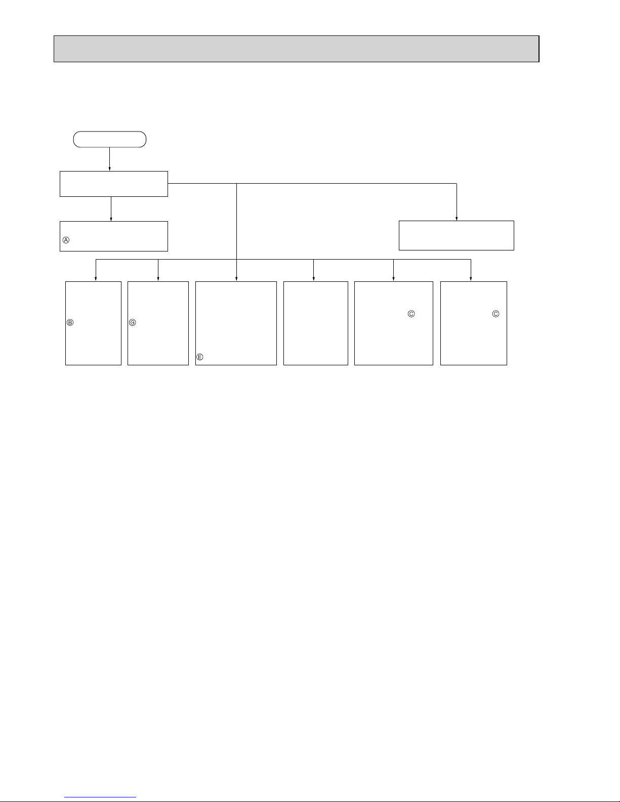
128
Operation start
Check the outdoor unit
LED indicator.
Refer to 11-6.
"Check of power supply".
,QGRRUXQLW
serial signal
error
Refer to 11-6.
"How to
check
miswiring and
serial signal
error".
&22/RU
HEAT
operation only
Refer to 11-6.
"Check of
R.V. coil".
:KHQFRROLQJ
room is not
cool.
Refer to 11-6.
"How to check
inverter/
compressor".
:KHQFRROLQJKHDW
exchanger of
non-operating indoor
unit frosts.
:KHQKHDWLQJQRQ
operating indoor unit
gets warm.
Refer to 11-6.
"Check of LEV".
:KHQKHDWLQJ
room does not get
warm.
Refer to 11-6.
"How to check
inverter/compressor".
&KHFNPLVSLSLQJ
shortage of capacity.
:KHQFRROLQJ
dew drops in the
non-operating
indoor unit.
Check of
misspiping.
Refer to 11-4.
"Troubleshooting check table".
Both LED1 and
LED 2 are OFF.
Both LED 1 and
LED 2 are lighting.
LED 1 or LED 2
has blinked.
11-3. INSTRUCTION OF TROUBLESHOOTING
• Check the indoor unit with referring to the indoor unit service manual, and confirm that there is any problem in the indoor
unit.
Then, check the outdoor unit with referring to this page.
OBH626H

129
11-4. TROUBLESHOOTING CHECK TABLE
MXZ-2D
No.
1
2
3
4
5
6
9
10
11
12
13
14
15
16
Symptom
'Outdoor
unit stops
and restarts
3 minutes
later' is
repeated.
Primary current protection
Secondary current protection
High-pressure protection
Defrosting in cooling
3 times
Lighted
Discharge temperature
protection
4 times
Lighted
Low discharge
temperature protection
Check the refrigerant circuit and the refrigerant amount.
Refer to 11-6.
"Check of LEV".
Refer to 11-6.
"Check of outdoor thermistors".
Refer to 11-6.
"Check of LEV".
Check the refrigerant circuit and the refrigerant amount.
These symptoms do not mean any abnormality of the
product, but check the following points.
Check if indoor filters are clogged.
Check if refrigerant is short.
Check if indoor/outdoor unit air circulation is short cycled.
Twice Lighted
Once
Lighted
The discharge temperature exceeds 100°C during operation.
The frequency of the compressor is kept 68 Hz (MXZ-2D33VA, MXZ-2D40
VA)/80 Hz (MSZ-2D42VA, MXZ-2D53VA/H) or more and the discharge
temperature is kept under 50°C (COOL mode)/40°C (HEAT mode) for
more than 40 minutes.
The input current exceeds 8 A (MXZ-2D33VA)/ 10 A (MXZ-2D40VA,
MXZ-2D42VA, MXZ-2D53VA/H).
The current of the compressor exceeds 17 A.
The indoor gas pipe temperature exceeds 45°C during heating.
The indoor gas pipe temperature falls 3°C or below during cooling.
Outdoor unit
operates.
17
18
19
20
7
LED1(Red) LED2(Yellow)
Lighted Twice
Outdoor power system
Lighted 3 times
Discharge temperature
thermistor
Outdoor heat exchanger
temperature thermistor
Defrost thermistor
Lighted 7 times
Nonvolatile memory data
Replace the inverter P.C. board.
Abnormal point / Condition Remedy
A short circuit is detected in the thermistor during operation, or when
an open circuit is detected in the thermistor after 5 minutes (in cooling)
and 10 minutes (in heating) of compressor start-up.
A short circuit is detected in the thermistor during operation, or when an
open circuit is detected in the thermistor after 5 minutes of compressor
start-up.
Replace the inverter P.C. board.
Indication
Overcurrent protection cut-out operates 3 consecutive times
within 1 minute after the compressor gets started.
A short circuit is detected in the thermistor during operation, or when an
open circuit is detected in the thermistor after 10 minutes of compressor
start-up.
Condition
The nonvolatile memory data cannot be read properly.
Fin temperature
thermistor
P.C board temperature
thermistor
Lighted 4 times
Ambient temperature
thermistor
A short or open circuit is detected in the thermistor during operation.
A short or open circuit is detected in the thermistor during operation.
5 timesLighted
Overcurrent
3 times Not lighted
Discharge temperature
protection
Fin temperature
protection
P.C. board temperature
protection
High-pressure
protection
Replace the inverter P.C. board.
Bus-bar voltage
protection
Not lighted
Outdoor fan motor
8 times Not lighted
Current sensor
protection
Replace the inverter P.C. board.
Not lighted
Compressor
Refer to 11-6.
"Check of outdoor fan motor".
Reconnect compressor connector.
Refer to 11-6.
"How to check inverter/compressor".
Check the stop valve.
Check the amount of gas and the refrigerant circuit.
Check the stop valve.
Check the amount of gas and the refrigerant circuit.
Refer to 11-6.
"Check of LEV".
&KHFNWKHUHIULJHUDQWFLUFXLWDQGWKHUHIULJHUDQWDPRXQW
5HIHUWR
"Check of outdoor fan motor".
Reconnect compressor connector.
Refer to 11-6.
"How to check inverter/compressor".
Check the stop valve.
Twice Not lighted
4 times Not lighted
5 times Not lighted
9 times Not lighted
14 A (MXZ-2D33VA)/18 A (MXZ-2D40VA, MXZ-2D42VA, MXZ-2D53VA/H)
current flows into intelligent power module.
The bus-bar voltage exceeds 430 V or falls to 50 V or below during
compressor operating.
Discharge temperature exceeds 116°C during operation. Compressor
can
restart if discharge temperature thermistor reads 100°C or less 3 minutes
later.
The fin temperature exceeds 90°C during operation.
The P.C. board temperature exceeds 78°C during operation.
Failure occurs 3 consecutive times within 30 seconds after the fan
gets started.
A short or open circuit is detected in the current sensor during
compressor operating.
The compressor does not synchronize with the operating power.
The outdoor heat exchanger temperature exceeds 70°C during cooling
or indoor gas pipe temperature exceeds 70°C during heating.
Outdoor unit
does not
operate.
Lighted Once
LEV and drain pump
Check the connection of the compressor connecting
wire.
Refer to 11-6.
"How to check inverter/compressor".
Check the stop valve.
Refer to 11-6.
"Check of outdoor thermistors".
Refer to 11-6.
"Check of outdoor thermistors".
Refer to 11-6.
"Check of outdoor thermistors".
Refer to 11-6.
"Check of LEV".
Check the drain pump of the indoor unit.
The indoor unit detects an abnormality in the LEV and drain pump.
Lighted 11 times
Stop valve
Closed valve
Closed valve is detected by compressor current.
(MXZ-2D33VA, MXZ-2D40VA)
Check the stop valve.
8
A closed valve and air trapped in the refrigerant circuit are detected
based on the temperature sensed by the indoor and outdoor thermistors
and the current of the compressor.
&KHFNIRUDJDVOHDNLQDFRQQHFWLQJSLSLQJHWF
&KHFNWKHVWRSYDOYH
5HIHUWR
"Check of outdoor refrigerant circuit".
Lighted 17 times
Outdoor refrigerant
system abnormality
13 times
10 times
OBH626H
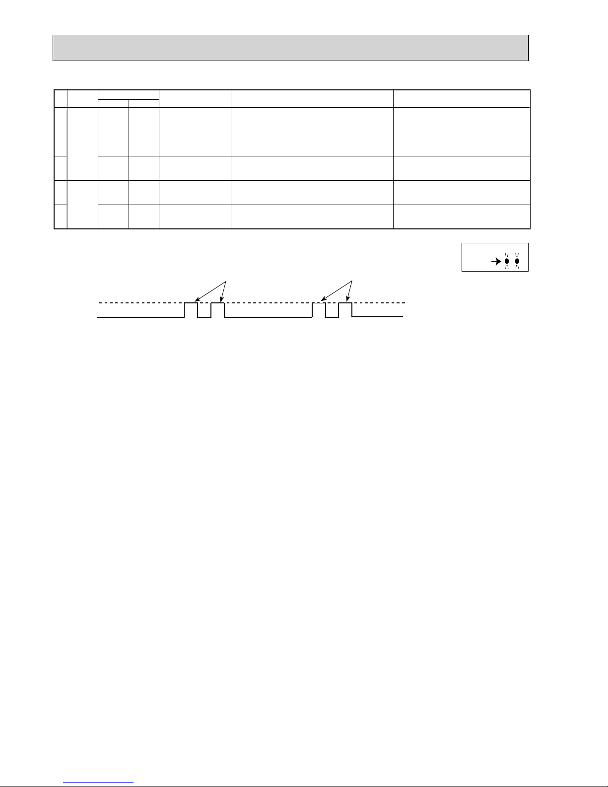
130
-
-
9 times
Lighted
Inverter check mode
Lighted
Lighted
Normal
The connector of compressor is disconnected.
Inverter check mode starts.
-
5 times
Lighted
Cooling high-pressure
protection
This symptom does not mean any abnormality of the
product, but check the following points.
Check if indoor filters are clogged.
Check if refrigerant is short.
Check if indoor/outdoor unit air circulation is short cycled.
The outdoor heat exchanger temperature exceeds 58°C during operation.
21
LED1(Red) LED2(Yellow)
Abnormal point / Condition Remedy
Indication
Condition
No.
Symptom
Outdoor unit
operates
normally.
23
24
Outdoor unit
operates.
Outdoor display P.C. board (Parts side)
Lighted
8 times
Lighted
Converter protection
A failure is detected in the operation of the converter during operation.
22
Check the voltage of power supply.
Replace the inverter P.C. board.
LED1
LED2
ON
OFF
2.5-second OFF 2.5-second OFF
0.5-second ON
0.5-second ON
NOTE: 1. The location of LED is illustrated at the right figure. Refer to 11-7.4.
2. LED is lighted during normal operation.
The flashing frequency shows the number of times the LED blinks after every 2.5-second OFF.
(Example) The flashing frequency is “2”.
OBH626H

131
MXZ-3D/4D/5D
LED1(Red) LED2(Yellow)
Lighted Twice
Outdoor power system
Lighted 3 times
Discharge temperature
thermistor
• Refer to 11-6. "Check of outdoor thermistors".
Outdoor heat exchanger
temperature thermistor
Defrost thermistor
Lighted 7 times
Nonvolatile memory data
• Replace the outdoor control P.C. board.
Lighted 8 times
Current sensor
• Replace the power P.C. board.
Lighted 11 times
Communication error
between P.C. boards
• Check the connecting wire between the outdoor control
P.C. board and the power P.C. board.
Lighted 12 times
Zero cross detecting
circuit
• Check the connecting wire between the outdoor control P.C.
board, the noise filter P.C. board and the power P.C. board.
Abnormal point / Condition Remedy
A short circuit is detected in the thermistor during operation, or an open
circuit is detected in the thermistor 5 minutes (in cooling) and 10
minutes (in heating) after compressor start-up.
A short circuit is detected in the thermistor during operation, or an open
circuit is detected in the thermistor 5 minutes after compressor start-up.
• Replace the outdoor control P.C. board.
Indication
Overcurrent protection cut-out operates 3 consecutive times
within 1 minute after the compressor gets started, or converter protection
or bus-bar voltage protection cut-out operates 3 consecutive times
within 3 minutes after start-up.
A short circuit is detected in the thermistor during operation, or an open
circuit is detected in the thermistor 10 minutes after compressor start-up.
Condition
The nonvolatile memory data cannot be read properly.
Fin temperature
thermistor
P.C board temperature
thermistor
Lighted 4 times
Ambient temperature
thermistor
Current sensor protection cut-out operates 2 consecutive times.
Communication error occurs twice between the outdoor control
P.C. board and the power P.C. board for more than 10 seconds.
The protection cut-out of the zero cross detecting circuit operates 10
consecutive times.
A short or open circuit is detected in the thermistor during operation.
A short or open circuit is detected in the thermistor during operation.
5 timesLighted
IPM protection
Lock protection
3 times Not lighted
Discharge temperature
protection
Fin temperature
protection
P.C. board temperature
protection
High-pressure
protection
8 times
Not lighted
Converter protection
• Replace the power P.C. board.
Bus-bar voltage
protection (1)
• Check the voltage of power supply.
• Replace the power P.C. board or the outdoor
control P.C. board.
• Refer to 11-6. "Check of bus-bar voltage".
Bus-bar voltage
protection (2)
13 times Not lighted
Outdoor fan motor
• Refer to 11-6. "Check of outdoor fan motor".
Lighted 8 times
Current sensor
protection
• Replace the power P.C. board.
Lighted 11 times
Communication protection
between P.C. boards
• Check the connecting wire between the outdoor
control P.C. board and the power P.C. board.
Lighted 12 times
Zero cross detecting circuit
protection
• Check the connecting wire between the outdoor control P.C.
board, the noise filter P.C. board and the power P.C. board.
• Check the amount of gas and the refrigerant circuit.
• Check the stop valve.
• Check the amount of gas and the refrigerant circuit.
• Refer to 11-6. "Check of LEV".
•Check the refrigerant circuit and the refrigerant amount.
•Refer to 11-6. "Check of outdoor fan motor".
• Reconnect compressor connector.
• Refer to 11-6.
"How to check inverter/compressor".
• Check the stop valve.
• Check the power module (PAM module).
Twice Not lighted
4 times Not lighted
5 times Not lighted
6 times Not lighted
9 times Not lighted
Overcurrent is detected 30 seconds after compressor start-up.
Overcurrent is detected within 30 seconds after compressor start-up.
The bus-bar voltage falls to 200 V or below during compressor
operating.
The bus-bar voltage exceeds 400 V (MXZ-3D54/3D68/4D72VA,
MXZ-3D54VA2)/430 V (MXZ-4D83/5D102VA) or falls to 50 V or below
while the compressor is operating.
Discharge temperature exceeds 116°C during operation. Compressor can
restart if discharge temperature thermistor reads 100°C or less 3 minutes
later.
The fin temperature exceeds 89°C during operation.
The P.C. board temperature exceeds 73°C (MXZ-3D54/3D68/4D72VA,
MXZ-3D54VA2)/87°C (MXZ-4D83/5D102VA) during operation.
High-pressure is detected with the high-pressure switch (HPS) during
operation. (MXZ-3D68/4D72/4D83/5D102VA)
Pre-heat protection
•
Replace the power P.C. board
.
A failure is detected in the operation of pre-heat.
(MXZ-3D54/3D68/4D72VA, MXZ-3D54VA2)
Failure occurs 3 consecutive times within 30 seconds after the fan
gets started.
A short or open circuit is detected in the current sensor while the
compressor is operating.
Communication error occurs between the outdoor control P.C.
board and the power P.C. board for more than 10 seconds.
Zero cross signal cannot be detected while the compressor is operating.
The outdoor heat exchanger temperature exceeds 70°C during cooling
or indoor gas pipe temperature exceeds 70°C during heating.
A failure is detected in the operation of the converter during operation.
Outdoor unit
does not
operate.
Lighted Once
LEV and drain pump
• Check the connection of the compressor connecting
wire.
• Refer to 11-6.
"How to check inverter/compressor".
• Check the stop valve.
• Refer to 11-6.
"Check of outdoor thermistors".
• Refer to 11-6.
"Check of outdoor thermistors".
• Refer to 11-6.
"Check of LEV".
• Check the drain pump of the indoor unit.
The indoor unit detects an abnormality in the LEV and drain pump.
No.
1
2
3
4
5
6
7
9
8
10
11
12
13
14
15
16
17
18
19
Symptom
'Outdoor unit
stops and
restarts 3
minutes
later' is
repeated.
OBH626H

132
Primary current protection
Secondary current protection
High-pressure protection
Defrosting in cooling
3 times
Lighted
Discharge temperature
protection
4 times
Lighted
Low discharge
temperature protection
• Check the refrigerant circuit and the refrigerant amount.
• Refer to 11-6.
"Check of LEV".
• Refer to 11-6.
"Check of outdoor thermistors".
• Refer to 11-6.
"Check of LEV".
• Check the refrigerant circuit and the refrigerant amount.
5 times
Lighted
Cooling high-pressure
protection
This symptom does not mean any abnormality of the
product, but check the following points.
• Check the indoor filters are not clogged.
• Check there is sufficient refrigerant.
• Check the indoor/outdoor unit air circulation is not short
cycling.
-
-
These symptoms do not mean any abnormality of the
product, but check the following points.
• Check the indoor filters are not clogged.
• Check there is sufficient refrigerant.
• Check the indoor/outdoor unit air circulation is not short
cycling.
Twice Lighted
Once Lighted
The outdoor heat exchanger temperature exceeds 58°C during operation.
9 times
Lighted
Inverter check mode
Lighted
Lighted
Normal
The unit is operated with emergency operation switch.
-
The primary current exceeds 15 A (MXZ-3D54/3D68/4D72VA,
MXZ-3D54VA2)/17 A (MXZ-4D83VA)/18 A (MXZ-5D102VA).
The current of the compressor exceeds 12 A (MXZ-3D54VA/3D54VA2)
/12.5A(MXZ-3D68/4D72VA) /10 A (MXZ-4D83/5D102VA).
The indoor gas pipe temperature exceeds 45°C during heating.
The indoor gas pipe temperature falls 3°C or below during cooling.
The discharge temperature exceeds 100°C during operation.
The frequency of the compressor is kept 80 Hz or more and the
discharge temperature is kept under 50°C (cooling) /40°C (heating)
for more than 40 minutes.
LED1(Red) LED2(Yellow)
Abnormal point / Condition Remedy
Indication
Condition
No.
20
21
22
23
24
25
26
Outdoor unit
operates
normally.
Outdoor unit
operates.
Symptom
Outdoor control P.C. board(Parts side)
LED2
LED1
Lighted
LED1
LED2
Lighted
MXZ-3D54/3D68/4D72VA
MXZ-3D54VA2
MXZ-4D83/5D102VA
ON
OFF
2.5-second OFF 2.5-second OFF
0.5-second ON 0.5-second ON
NOTE: 1. The location of LED is illustrated at the right figure. Refer to 11-7.2.
2. LED is lighted during normal operation.
The flashing frequency shows the number of times the LED blinks after every 2.5-second OFF.
(Example) The flashing frequency is “2”.
OBH626H

133
No. Symptom
Indication
Abnormal point / Con-
dition
Condition Remedy
LED1(Red) LED2(Yellow)
1 Outdoor
unit does
not operate.
Lighted Once LEV and drain pump
The indoor unit detects an abnormality in the LEV
and drain pump.
• Refer to 11-6.
"Check of LEV".
• Check the drain pump of the indoor unit.
2
Lighted Twice
Outdoor power
system
Overcurrent protection cut-out operates 3 consecutive times within 1 minute after the compressor
gets started, or converter protection cut-out or busbar voltage protection cut-out operates 3 consecutive times within 3 minutes after start-up.
• Check the connection of the compressor connecting wire.
• Refer to 11-6.
"How to check inverter/compres-
sor".
• Check the stop valve.
3
Lighted 3 times
Discharge temperature
thermistor
A short circuit is detected in the thermistor during
operation, or an open circuit is detected in the
thermistor after 10 minutes of compressor start-up.
• Refer to 11-6.
"Check of outdoor thermistors".
4
Lighted 4 times
Fin temperature
thermistor
A short or open circuit is detected in the thermistor
during operation.
• Refer to 11-6.
"Check of outdoor thermistors".
P. C. board temperature thermistor
• Replace the outdoor control P.C. board.
5
Lighted 5 times
Ambient temperature
thermistor
A short or open circuit is detected in the thermistor
during operation.
• Refer to 11-6.
"Check of outdoor thermistors".
Outdoor heat exchanger temperature
thermistor
A short circuit is detected in the thermistor during
operation, or an open circuit is detected in the
thermistor after 5 minutes (in cooling) and 10
minutes (in heating) of compressor start-up.
Defrost thermistor
A short circuit is detected in the thermistor during
operation, or an open circuit is detected in the
thermistor after 5 minutes of compressor start-up.
6
Lighted 6 times
Zero cross detecting
circuit (outdoor control
P.C. board)
Zero cross signal can not be detected. • Replace the outdoor control P.C. board.
7
Lighted 7 times Outdoor control system
The nonvolatile memory data cannot be read
properly.
• Replace the outdoor control P.C. board.
8
Lighted 8 times Current sensor
Current sensor protection cut-out operates 2 consecutive times.
• Replace the outdoor power P.C. board.
9
Lighted 11 times
Communication error
between P.C. boards
The communication protection cut-out between
boards operates 2 consecutive times.
• Check the connecting wire between outdoor control P.C. board and outdoor power P.C. board.
M-NET communication
error
M-NET adapter P.C. board detects an abnormality
in the communication error.
• Check the connecting wire between M-NET
adapter P.C. board and outdoor control P.C.
board, or terminal bed.
10
Lighted 12 times
Zero cross detecting
circuit (outdoor power
P.C. board)
The protection cut-out of the zero cross detecting
circuit operates 10 consecutive times.
• Replace the outdoor power P.C. board.
11
Lighted 13 times Current sensor
A short or open circuit is detected in the input current detection circuit during operation.
• Replace the outdoor power P.C. board.
12
Lighted 14 times Voltage sensor
A short or open circuit is detected in the input voltage detection circuit during operation.
• Replace the outdoor power P.C. board.
13 Lighted 15 times Relay operation No relay operation is detected during operation. • Replace the outdoor power P.C. board.
14 'Outdoor unit
stops and
restarts
3 minutes
later' is
repeated.
Twice Not lighted
IPM protection
Overcurrent is detected after 30 seconds of compressor start-up.
• Reconnect compressor connector.
• Refer to 11-6.
"How to check inverter/
compressor".
• Check the stop valve.
• Check the power module (PAM module).
Lock protection
Overcurrent is detected within 30 seconds of compressor start-up.
15
3 times Not lighted
Discharge temperature
protection
The discharge temperature exceeds 116°C during
operation.
Compressor can restart if discharge temperature
thermistor reads 100°C or less 3 minutes later.
• Check the amount of gas and refrigerant circuit.
• Refer to 11-6.
"Check of LEV".
16
4 times Not lighted
Fin temperature
protection
The fi n temperature exceeds during operation.
•Check refrigerant circuit and refrigerant amount.
•Refer to 11-6.
"Check of outdoor fan motor".
P.C. board temperature
protection
The P.C. board temperature exceeds during operation.
17
5 times Not lighted
High-pressure
protection
High-pressure is detected with the high-pressure
switch (HPS) during operation.
• Check around of gas and the refrigerant circuit.
• Check the stop valve.
The outdoor heat exchanger temperature exceeds
70°C during cooling or the indoor gas pipe temperature exceeds 70°C during heating.
18
6 times Not lighted Pre-heating protection Overcurrent is detected during pre-heating.
• Reconnect compressor connector.
• Refer to 11-6.
"How to check inverter/
compressor".
• Check the power module.
19
8 times Not lighted Converter protection
A failure is detected in the operation of the converter during operation.
• Replace the outdoor power P.C. board.
20
9 times Not lighted
Bus-bar voltage
protection
The bus-bar voltage exceeds 400 V or falls to low
level during compressor operating.
• Check the voltage of power supply.
• Replace the outdoor power P.C. board or the outdoor control P.C. board.
• Refer to 11-6.
"Check of bus-bar voltage".
MXZ-6D
OBH626H

134
No. Symptom
Indication
Abnormal point / Con-
dition
Condition Remedy
LED1(Red) LED2(Yellow)
21 'Outdoor unit
stops and
restarts
3 minutes
later' is
repeated.
13 times Not lighted Outdoor fan motor
A failure occurs 3 consecutive times within 30
seconds after the fan gets started.
• Refer to 11-6.
"Check of outdoor fan motor".
22
Lighted 8 times
Current sensor protection
A short or open circuit is detected in the current
sensor during compressor operating.
• Replace the outdoor power P.C. board.
23
Lighted 11 times
Communication
between P.C. boards
protection
Communication error occurs between the outdoor
control P.C. board and outdoor power P.C. board
for more than 10 seconds.
• Check the connecting wire between outdoor control P.C. board and outdoor power P.C. board.
24
Lighted 12 times
Zero cross detecting
circuit (outdoor power
P.C. board)
Zero cross signal cannot be detected while the
compressor is operating.
• Replace the outdoor power P.C. board.
25 Outdoor unit
operates.
Once Lighted
Primary current protection
The input current exceeds 15 A.
These symptoms do not mean any abnormality of
the product, but check the following points.
• Check if indoor fi lters are clogged.
• Check if refrigerant is short.
• Check if indoor/outdoor unit air circulation is short
cycled.
26
Twice Lighted
High-pressure protection
The indoor gas pipe temperature exceeds 45°C
during heating.
Defrosting in cooling
The indoor gas pipe temperature falls 3°C or below
during cooling.
27
3 times Lighted
Discharge temperature
protection
The frequency of the compressor is kept 80 Hz or
more and the discharge temperature is kept under
50°C(COOL mode)/40°C(HEAT mode) for more
than 40 minutes.
• Check refrigerant circuit and refrigerant amount.
• Refer to 11-6.
"Check of LEV".
• Refer to 11-6.
"Check of outdoor thermistors".
28
4 times Lighted
Low discharge
temperature protection
The frequency of the compressor is kept 80 Hz or
more and the discharge temperature is kept under
39°C for more than 20 minutes.
• Refer to 11-6.
"Check of LEV".
• Check refrigerant circuit and refrigerant amount.
29
5 times Lighted
Cooling high-pressure
protection
The outdoor heat exchanger temperature exceeds
58°C during operation.
This symptom does not mean any abnormality of
the product, but check the following points.
• Check if indoor fi lters are clogged.
• Check if refrigerant is short.
• Check if indoor/outdoor unit air circulation is short
cycled.
30
Outdoor
unit
operates
normally.
9 times Lighted Inverter check mode
The unit is operated with emergency operation
switch.
—
31
Lighted Lighted Normal
——
NOTE 1. The location of LED is illustrated at the right figure. Refer to 11-7.2.
2. LED is lighted during normal operation.
The flashing frequency shows the number of times the LED blinks after every 2.5-second OFF.
(Example) When the flashing frequency is “2”.
ON
OFF
2.5-second OFF
2.5-second OFF
0.5-second ON
0.5-second ON
LED1
LED2
Lighted
Outdoor control P.C. board
(Parts side)
OBH626H

135
Part name Check method and criterion
Defrost thermistor (RT61)
Fin temperature thermistor (RT64)
Ambient temperature thermistor (RT65)
Outdoor heat exchanger
temperature thermistor (RT68)
Measure the resistance with a tester.
Refer to 11-7. "TEST POINT DIAGRAM AND VOLTAGE" 1. "Inverter P.C. board", 2.
"Outdoor control P.C. board " or 3. "Outdoor power P.C. board" for the chart of thermistor.
Discharge temperature thermistor
(RT62)
Measure the resistance with a tester.
Before measurement, hold the thermistor with your hands to warm it up.
Refer to 11-7. "TEST POINT DIAGRAM AND VOLTAGE" 1. "Inverter P.C. board", 2.
"Outdoor control P.C. board ", for the chart of thermistor.
Compressor Measure the resistance between terminals with a tester.
(Winding temperature : -10°C ~ 40°C)
Normal (Each phase)
MXZ-2D33VA
MXZ-2D40VA
MXZ-2D42VA
MXZ-2D53VA
MXZ-2D53VAH
MXZ-3D54VA
MXZ-3D54VA2
MXZ-3D68VA
MXZ-4D72VA
MXZ-4D83VA
MXZ-5D102VA
MXZ-6D122VA
1.49
~ 1.84 0.86 ~ 1.06 0.63 ~ 0.78 1.29 ~ 1.49 0.77 ~ 0.95
Outdoor fan motor
23
W
U
V
1
WHT
RED BLK
MXZ-2D33VA/40VA/42VA/53VA
MXZ-2D53VAH
MXZ-4D83VA/5D102VA
Measure the resistance between lead wires with a tester.
(Part temperature : -10°C ~ 40°C)
Normal (Each phase)
MXZ-2D
MXZ-4D83VA
MXZ-5D102VA
12 ~ 16 13.4 ~ 16.4
Outdoor fan motor
MXZ-3D54VA/3D54VA2/3D68VA/4D72VA/6D122VA
Refer to 11-6. .
R.V. coil
Measure the resistance with a tester. (Part temperature : -10°C ~ 40°C)
Normal
MXZ-2D33VA
MXZ-2D40VA
MXZ-2D42VA
MXZ-2D53VA
MXZ-2D53VAH
MXZ-4D83VA
MXZ-5D102VA
MXZ-3D54VA
MXZ-3D54VA2
MXZ-3D68VA
MXZ-4D72VA
MXZ-6D122VA
1.2 k
~ 1.56 k 1.26 k ~ 1.62 k 1.24 k ~ 1.86 k
Linear expansion valve
LEV
WHT
RED
YLW
ORN
BLU
Measure the resistance with a tester. (Part temperature : -10°C ~ 40°C)
Color of lead wire Normal
WHT - RED
37.4
~ 53.9
RED - ORN
YLW - RED
RED - BLU
High pressure switch (HPS)
MXZ-3D54VA2-E3,
ER3, ET3
MXZ-3D68VA/4D72VA
MXZ-4D83VA/5D102VA
MXZ-6D122VA
Pressure
Normal
HPS
MXZ-3D54VA2-E3,
ER3, ET3
MXZ-3D68VA-E3,
ER3, ET3
MXZ-4D72VA-E3,
ER3, ET3
MXZ-3D68VA-E1,
E2
,
ER2, ET2
MXZ-4D72VA-E1,
E2
,
ER2, ET2
MXZ-4D83VA/5D102VA
MXZ-6D122VA
3.43 0.15 MPa 3.7 0.3 MPa 3.43 0.15 MPa Close
4.41
0.1 MPa 4.8 0.2 MPa 4.41 0.1 MPa Open
Defrost heater
MXZ-2D53VAH
Measure the resistance with a tester. (Part temperature : -10°C ~ 40°C)
Normal
349
~ 428
W
U
V
WHT
RED
BLK
11-5. TROUBLE CRITERION OF MAIN PARTS
MXZ-2D33VA MXZ-2D40VA MXZ-2D42VA MXZ-2D53VA MXZ-2D53VAH
MXZ-3D54VA MXZ-3D54VA2 MXZ-3D68VA MXZ-4D72VA MXZ-4D83VA MXZ-5D102VA
MXZ-6D122VA
OBH626H

136
Check of power supply
• When outdoor unit does not operate, LED on outdoor P.C. board is not lighting.
11-6. TROUBLESHOOTING FLOW
Turn ON the power supply.
No
Yes
No
Yes
No
Yes
No
Yes
No
Yes
+
-
Check the main power supply circuit for proper connections.
Is there voltage of 230 VAC in the
power supply terminal block?
Is there voltage of 230 VAC between
LD66B and X64 on the inverter
P.C. board?
Check the power supply and correct them.
Replace the outdoor display P.C. board.
Replace the inverter P.C. board.
Is there voltage of 230 VAC between
LD66A and LD70 on the inverter
P.C. board?
Replace the reactor.
Is there voltage of 325 VDC between
DB61 and DB61 on the inverter
P.C. board?
Replace the inverter P.C. board.
Is there voltage of 5 VDC between
CN936 and CN936 on the
outdoor display P.C. board?
Check the connected wire between
the inverter P.C. board and outdoor
display P.C. board and correct it.
Replace the inverter P.C. board.
MXZ-2D33VA/2D40VA/2D42VA/2D53VA/2D53VAH
OBH626H

137
MXZ-3D54VA/3D54VA2/3D68VA/4D72VA/4D83VA/5D102VA
MXZ-6D122VA
Check the main power supply circuit for proper connections.
Is there voltage of 230 VAC in the
power supply terminal block?
Is the output voltage from the noise
filter P.C. board 230 VAC?
Is the input voltage to the outdoor
electronic control P.C. board 325 VDC?
Check the power supply and correct them.
Replace the outdoor control P.C. board.
Replace the noise filter P.C. board.
Is the input voltage to the power P.C.
board 230 VAC?
Replace the reactor.
Turn ON the power supply.
No
Yes
Yes
No
Yes
No
Yes
No
Replace the outdoor power P.C. board.
Turn ON the power supply.
No
Yes
Yes
No
No
Yes
Check the main power supply circuit for proper connections.
Is there voltage of 230 VAC in the
power supply terminal block?
Is the output voltage from the outdoor
power P.C. board 325 VDC?
Check the power supply cable.
Replace the outdoor power P.C. board.
Turn OFF the power supply and recconnect the reactor.
Is the reactor short-circuited?
Replace the reactor.
Replace the outdoor control P.C. board.
OBH626H

138
LED indication for communication status
Communication status is indicated by the LED.
Unit status No
Blinking: normal communication
Lighted: abnormal communication or not connected
seYNot lighted: The outdoor P.C. board is abnormal.
NOTE: "Lighted" and "Not lighted" in the table below
does not indicate abnormal.
*1 Turn OFF the power supply before
replacing the indoor electronic control
P.C. board.
MXZ-2D33/2D40/2D42/2D53VA/2D53VAH
Refer to indoor unit service manual.
Outdoor display P.C. board
oNoN
LED 1 LED 2
Unit A Unit B
status status
Yes
oN
seY
seY
No
Yes
No (Lighted or
not lighted)
*1 Turn OFF the power supply before replacing the indoor electronic
control P.C. board.
Refer to indoor unit service manual.
*3 Turn OFF the power supply before replacing the inverter P.C. board.
Be careful of residual voltage of smoothing capacitor.
*4 Remove the short-circuit between outdoor terminal block
S2 and S3. Connect the indoor/outdoor connecting wire.
Turn ON the power supply.
Is there rated voltage
between outdoor
terminal block S1 and S2 ?
Check the power supply
and correct the problem.
Press the EMERGENCY
OPERATION switch
once.
Does the OPERATION
INDICATOR lamp light
up? <Confirmation of
the power to the indoor
unit>
Is there rated
voltage between
outdoor terminal
block S1 and S2?
Check the indoor/outdoor
connecting wire and
correct the problem.
Replace the indoor
electronic control
P.C. board. *1
Is serial signal error
indicated 6 minutes
later?
Is there any miswiring,
poor contact, or wire
disconnection of the
indoor/outdoor
connecting wire?
Check the indoor/outdoor
connecting wire and
correct the problem.
Turn OFF the power supply.
Turn ON the power supply.
Does the LED on the
outdoor display P.C.
board or the outdoor control
P.C. board repeat quick
BLINKING and OFF? *2
Replace the indoor
electronic control
P.C. board. *1 *4
*2 The LED indicates the status of serial
communication.
Check the communication status.
Replace the inverter P.C.
board or the outdoor control
P.C. board. *3 *4
If the trouble sometimes occurs,
possible causes are as follows:
3RRUFRQQHFWLRQRIWKHLQGRRU
outdoor connecting wire
Check for intermediate connection of
the indoor/outdoor connecting wire,
loose connection to the terminal block,
and cut wire inside the cable.
If any of them is found, correct the
problem(s).
(IIHFWVRIWKHLQYHUWHUOLJKWLQJ
on the indoor unit
If the trouble occurs or does not occur
depending on whether the light is on
or off, distance the lighting from the
indoor unit or apply the glass filter on
the receiving part of the indoor unit.
1RLVHRQWKHLQGRRURXWGRRU
connecting wire
Pass the indoor/outdoor connecting
wire through a different route if the
existing wiring is arranged as below:
7KHLQGRRURXWGRRUFRQQHFWLQJZLUH
runs near the
power supply cable of
other equipment.
7KHLQGRRURXWGRRUFRQQHFWLQJZLUH
is detoured and run long.
Remove the
indoor/outdoor connecting
wire from the outdoor
terminal block connected
with the indoor unit on
which miswiring or the
serial signal error is
indicated. Short-circuit
between S2 and S3 of the
outdoor terminal block .
Outdoor control P.C. board
Blinking
LED 1 LED 3LED 2
Pattern
1
2
Unit B
status
Unit D
status
Unit A
status
Unit C
status
Unit E
status
Not lighted
Outdoor control P.C. board
Blinking
LED 3 LED 1LED 2
Pattern
1
2
Unit B
status
Lighted
Unit A
status
Unit D
status
Not lighted
Unit C
status
MXZ-3D54/3D68/4D72VA
MXZ-3D54VA2
MXZ-4D83/5D102VA
LED1 LED2
LED3
LED3 LED2
LED1
LED1 LED2
How to check miswiring and serial signal error (when outdoor unit does not work)
• When the indoor unit does not operate, it cannot be operated either with the remote controller or with the
EMERGENCY OPERATION switch.
• When the outdoor unit does not operate, the OPERATION INDICATOR lamp on the indoor unit flashes ON and OFF
every 0.5-second.
MXZ-2D/3D/4D/5D
OBH626H
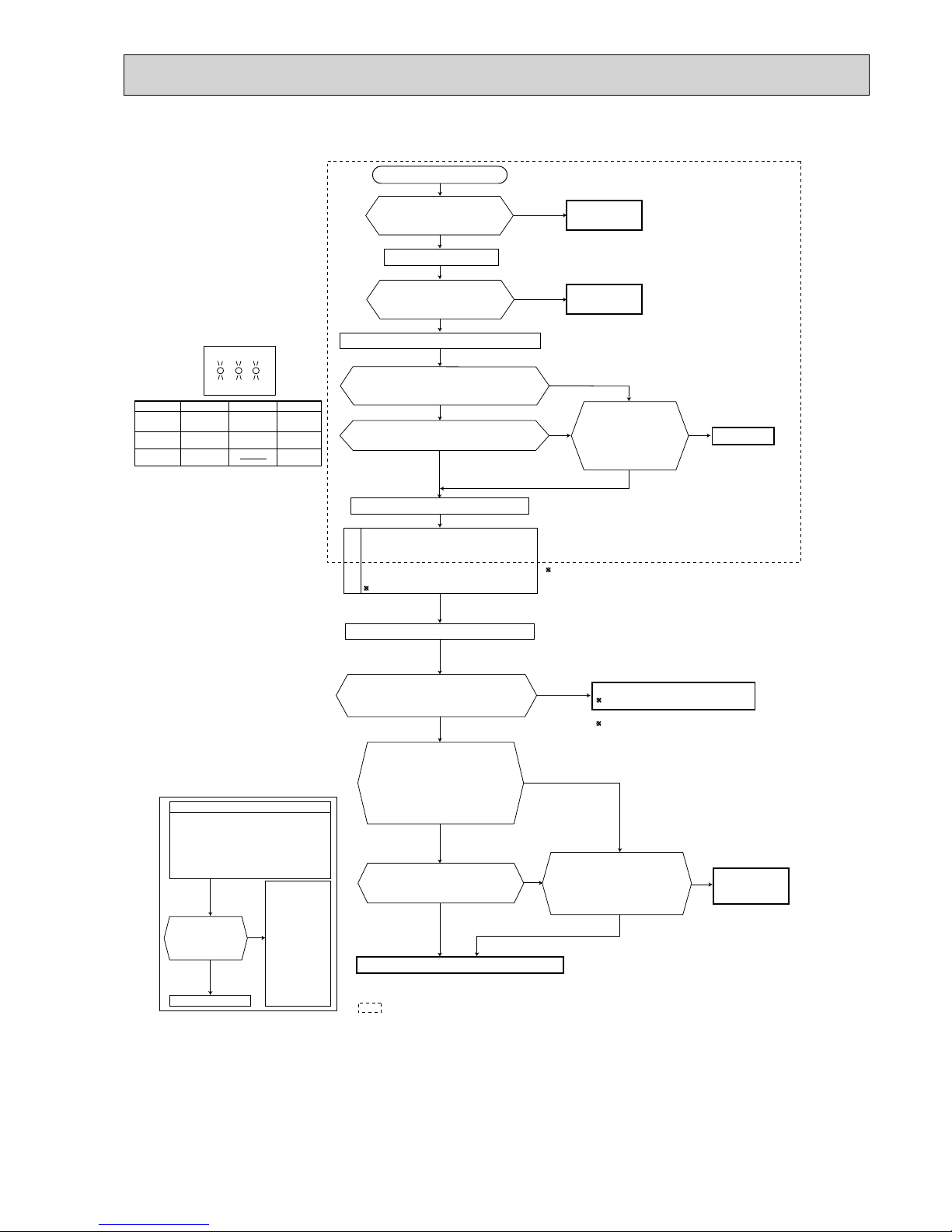
139
MXZ-6D122VA
Is there rated voltage in
the power supply?
Is there any miswiring,
poor contact, or wire
disconnection of the
indoor/outdoor
connecting wire?
1 Miswiring may damage indoor electronic control
P.C. board during the operation.
Be sure to confirm the wiring is correct before the
operation starts.
(Lighted
or
not lighted)
No
Yes
No
Yes
Yes
No
Yes
No
Be sure to release the failure-mode
recall function after checking.
No
No
Yes
No
Yes
Yes
Yes
No
Yes
Refer to indoor unit service manual.
Turn OFF the power supply.
Turn ON the power supply.
Is there rated voltage between
outdoor terminal block S1 and
S2?
Does the left lamp of OPERATION
INDICATOR lamp light up?
<Confirmation of the power to the indoor unit>
Press EMERGENCY OPERATION switch once.
Check the power
supply.
A
Turn OFF the power supply.
Check once more if the indoor/outdoor
connecting wire is not miswiring.
Bridge the outdoor terminal block S2 and
S3.
1
B
Turn ON the power supply.
Check the wiring.
Correct them.
Turn OFF the power supply.
Remove the bridge between
outdoor terminal block S2 and S3.
Turn ON the power supply.
Is there amplitude of 10 to 20 VDC
between outdoor terminal block S2
and S3? <Confirmation of serial
signal>
Is there rated voltage between
indoor terminal block S1 and S2?
<Confirmation of power voltage>
Replace the indoor electronic control P.C. board.
2 Be careful of the residual
voltage of smoothing capacitor.
Replace the outdoor control P. C. board.
2
Is there any error of the
indoor/outdoor connecting wire,
such as the damage of the wire,
intermediate connection, poor
contact to the terminal block?
Replace the
indoor/outdoor
connecting wire.
Is serial signal
error indicated
6 minutes later?
Yes
No
· Turn OFF inverter-controlled lighting
equipment.
· Turn OFF the power supply and then
turn ON again.
· Press EMERGENCY OPERATION
switch.
B
· Reinstall
either the
unit or the
light away
from each
other.
· Attach a filter
on remote
control
receiving
section of
the indoor
unit.
A
Is serial signal error indicated 6 minutes later?
No
Does the LED on the outdoor control P.C.
board repeat "3.6-second-OFF
and 0.8-second-ON quick blinking"?
LED indication
for communication status
Communication status is indicated
by the LED.
Blinking: normal communication
Lighting: abnormal communication or
not connected
Pattern 1 and 2 is repeatedly displayed
alternately. Each pattern is displayed for
15 seconds.
NOTE: "Lighting" in the table below does not
indicate abnormal communication.
Unit status
Outdoor control P.C. board
Blinking
LED1 LED2
LED3
LED 1 LED 3LED 2
Pattern
1
2
3
Unit B
status
Unit C
status
Unit A
status
Unit D
status
Unit E
status
Not lighted
Lighted
Blinking
OBH626H

140
How to check inverter/compressor
Disconnect the connector (CNMC) between the inverter P.C. board/the
outdoor control P.C. board and compressor, or disconnet the terminal of the
compressor.
3 minutes after turning ON the power supply, start EMERGENCY OPERATION.
Is output balanced?
Replace the inverter P.C. board or
the outdoor power P.C. board.
(Except MXZ-2D)
Is the input voltage to the outdoor control
P.C. board 370 VDC or more?
Replace the outdoor power P.C. board.
Replace the compressor.
Measure the voltage between each lead
wire leading to the compressor.
U (BLK) - V (WHT)
V (WHT) - W (RED)
W (RED) - U (BLK)
Is there voltage of 50 VAC - 250 VAC? * 1, * 2
Turn OFF the power supply, and measure the
compressor winding resistance between the
compressor terminals.
Is there resistance between each
terminal normal? (Refer to 11-5.)
Reconnect the lead wire of compressor.
3 minutes after turning ON the power supply,
start EMERGENCY OPERATION.
Clarify the causes by counting time until the
inverter stops.
0 to 10 seconds: compressor layer short
10 to 60 seconds: compressor lock
60 seconds to 5minutes: refrigerant circuit defective
5 minutes or more: normal
No
No
Yes
Yes
No
Yes
No
Yes
* 1 After the outdoor fan starts running, wait for 1 minute or
more before measuring the voltage.
The output voltage values have the tolerance of ± 20%.
* 2 The output differs depending on the capacity or the
number of indoor units to be operated.
• In heating, the room does not get warm.
• In cooling, the room does not get cool.
OBH626H

141
Check of outdoor thermistors
• The thermistor is abnormal.
Is the resistance of the thermistor normal? (Refer to 11-5.)
Disconnect the connector in the following table.
Does the unit operate 10 minutes or more without
showing thermistor abnormality?
Replace the thermistor except RT64.
In case that RT64 is abnormal,
replace the inverter P.C. board or the
outdoor power P.C. board since RT64
is combined with this board.
Normal
Replace the inverter P.C. board, outdoor
control P.C. board or the outdoor power
P.C. board.
Yes
Yes
No
No
Reconnect the connector and disconnect the lead wire
leading to the compressor.
3 minutes after turning ON the power supply, start
EMERGENCY OPERATION.
Thermistor
Defrost
Discharge temperature
Fin temperature
Ambient temperature
Outdoor heat exchanger temperature
Symbol
RT61
RT62
RT64
RT65
RT68
Connector, Pin No.
CN641 pin1 and pin2
CN641 pin3 and pin4
CN642 pin1 and pin2
CN643 pin1 and pin2
CN644 pin1 and pin3
Inverter P.C. board
Outdoor control P.C. board
Outdoor power P.C. board
Outdoor control P.C. board
Outdoor control P.C. board
Outdoor power P.C. board
Outdoor control P.C. board
Board
Thermistor
Defrost
Discharge temperature
Fin temperature
Ambient temperature
Outdoor heat exchanger temperature
Symbol
RT61
RT62
RT64
RT65
RT68
Connector, Pin No.
CN661 pin1 and pin2
CN661 pin3 and pin4
CN9 pin1 and pin2
CN665 pin1 and pin2
CN661 pin7 and pin8
Board
Thermistor
Defrost
Discharge temperature
Fin temperature
Ambient temperature
Outdoor heat exchanger temperature
Symbol
RT61
RT62
RT64
RT65
RT68
Connector, Pin No.
CN661 pin1 and pin2
CN661 pin3 and pin4
CN3 pin1 and pin2
CN661 pin7 and pin8
CN663 pin1 and pin2
Board
MXZ-3D54/3D68/4D72VA
MXZ-3D54VA2
MXZ-2D30/2D40/2D42/2D53VA/2D53VAH
MXZ-4D83/5D102VA
MXZ-6D122VA
Thermistor
Defrost
Discharge temperature
Outdoor heat exchanger temperature
Ambient temperature
Fin temperature
Symbol
RT61
RT62
RT68
RT65
RT64
Connector, Pin No.
Between CNTH1 pin1 and pin2
Between CNTH1 pin3 and pin4
Between CNTH1 pin7 and pin8
Between CNTH2 pin1 and pin2
Between CN171 pin1 and pin2
Outdoor control P.C. board
Outdoor power P.C. board
Board
OBH626H

142
Check of LEV
No
Yes
Yes
No
Turn ON the power supply to the outdoor unit after checking
LEV coil is mounted to the LEV body securely.
Is "click - click" sound heard?
Or, do you feel vibration of LEV coil with your hand?
Disconnect the connectors.
MXZ-2D
CN724: LEV A, CN725: LEV B
Other models
CN791: LEV A, CN792: LEV B,
CN793: LEV C, CN794: LEV D,
CN795: LEV E, CN796: LEV F
Normal
Is the resistance of the LEV coil normal?
(Refer to 11-5.)
Replace the inverter P.C. board or
the outdoor control P.C. board.
Replace LEV coil.
• In cooling, the heat exchanger of non-operating indoor unit has frosted.
• In heating, non-operating indoor unit gets warm.
MXZ-2D MXZ-3D/4D/5D/6D
CN724
CN725
Inverter P.C. board
Outdoor control
P.C. board
CN791
CN792
CN793
CN794
CN795
CN796
―
OBH626H

143
Check of outdoor fan motor
• Fan motor does not operate or stops operating shortly after starting the operation.
Disconnect CN932 and measure the
resistance of the outdoor fan motor.
Turn ON the breaker.
Rotate the outdoor fan motor manually and
measure the voltage of CN931.
Between (+) and (-)
Between (+) and (-)
Between (+) and (-)
Is the resistance of outdoor fan motor
normal? (Refer to 11-5.)
Does the outdoor fan motor rotate smoothly?
Does the voltage between each terminal
become 5 VDC and 0 VDC repeatedly?
Replace the outdoor fan motor.
Replace the inverter P.C. board or the outdoor
control P.C. board.
No
Yes
Yes
No
Yes
No
CN931
CN932
Outdoor control P.C. board
MXZ-2D MXZ-4D83VA/5D102VA
Inverter P.C. board
MXZ-2D33VA/2D40VA/2D42VA/2D53VA/2D53VAH
MXZ-4D83VA/5D102VA
OBH626H
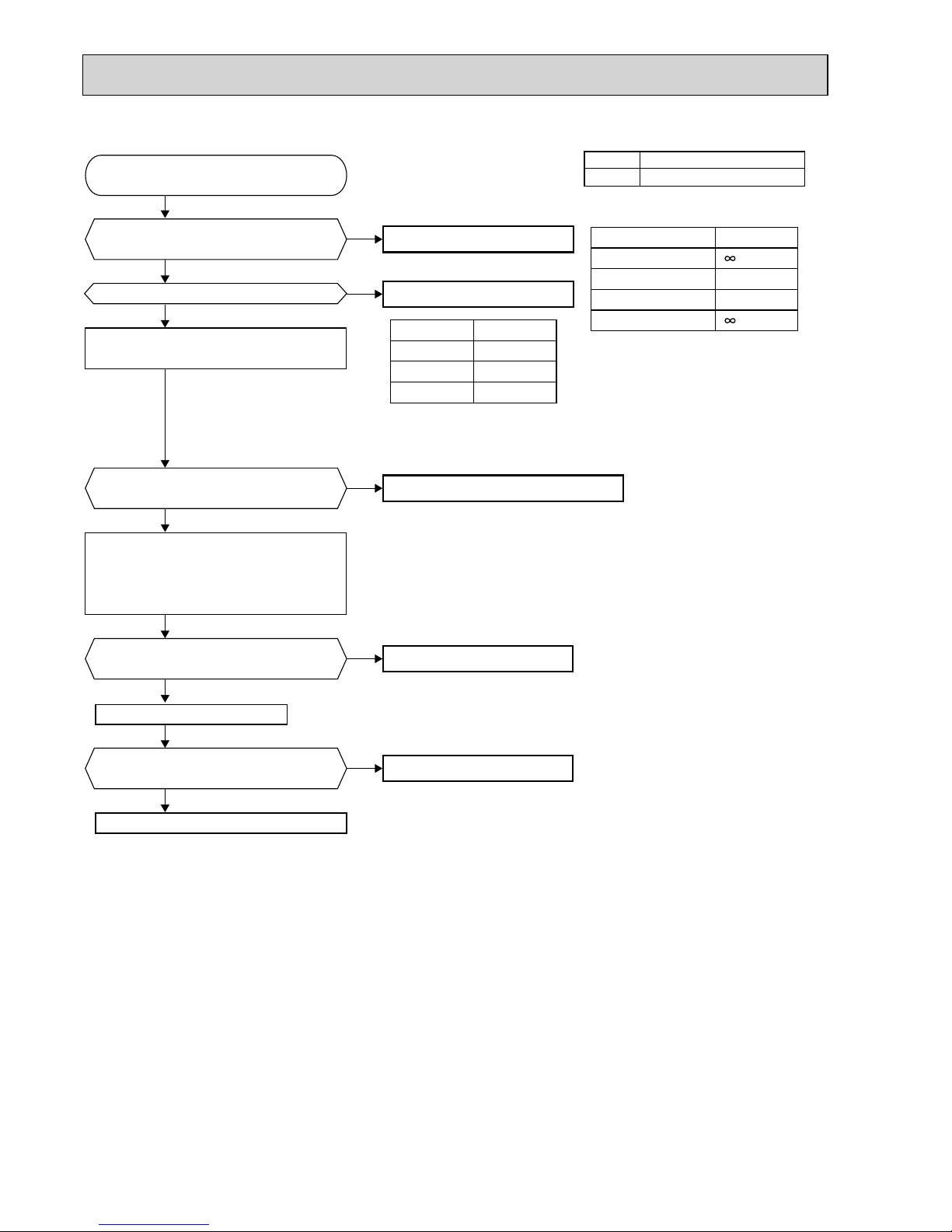
144
MXZ-3D54VA/3D54VA2/3D68VA/4D72VA
No
Yes
No
Yes
No
Yes
No
Yes
No
Yes
Disconnect CN931 and measure the
resistance of the outdoor fan motor.
Is the resistance of outdoor fan motor
normal? (Refer to right table)
Turn on the power supply to start operation
and measure the voltage of connector CN931.
Turn OFF the power supply and connect
the connector CN931.
Turn ON the power supply and measure
the voltage of connector CN931 while
rotating the motor by the hand.
Does the outdoor fan motor rotate smoothly?
Replace the outdoor fan motor.
Resistance
60 kΩ
160 kΩ
Measuring points
* To measure the resistance, connect
the negative (-) end of the tester to pin 4.
* To measure the voltage, connect the negative (-) end of the tester to pin 4.
* Voltage between pin 4 and 6 should be measured within 1 minute
after the operation starts.
pin 1 - pin 4
pin 5 - pin 4
pin 6 - pin 4
pin 7 - pin 4
Voltage
15 VDC
325 VDC
1 - 5 VDC
CN931
pin 1 - pin 4
pin 5 - pin 4
pin 6 - pin 4
Is the voltage of connector CN931
normal? (Refer to right table.)
Replace the outdoor control P.C. board.
Does the voltage between pin 7 and pin 4 of
connector CN931 repeat 0 VDC and 5 VDC?
Replace the outdoor fan motor.
Does the fan motor operate for about
5 seconds?
Replace the outdoor fan motor.
Replace the outdoor fan motor.
Replace the outdoor control P.C. board.
Start operation.
CN931
Outdoor control P.C. board
MXZ-3D54VA/3D54VA2/3D68VA/4D72VA
OBH626H

145
MXZ-6D122VA
No
Yes
No
Yes
No
Yes
No
Yes
No
Yes
Disconnect CNF1 and measure the
resistance of the outdoor fan motor.
Is the resistance of outdoor fan motor
normal? (Refer to right table)
Turn on the power supply to start operation
and measure the voltage of connector CNF1.
Turn OFF the power supply and connect
the connector CNF1.
Turn ON the power supply and measure
the voltage of connector CNF1 while
rotating the motor by the hand.
Does the outdoor fan motor rotate smoothly?
Replace the outdoor fan motor.
Resistance
N
N
Measuring points
* To measure the resistance, connect
the negative (-) end of the tester to pin 4.
* To measure the voltage, connect the negative (-)
end of the tester to pin 4.
* Voltage between pin 4 and 6 should be measured
within 1 minute after the operation starts.
pin 1 - pin 4
pin 5 - pin 4
pin 6 - pin 4
pin 7 - pin 4
Voltage
15 VDC
325 VDC
1 - 5 VDC
CNF1
pin 1 - pin 4
pin 5 - pin 4
pin 6 - pin 4
Is the voltage of connector CNF1
normal? (Refer to right table.)
Does the voltage between pin 7 and pin 4
of connector CNF1 repeat 0V and 5V?
Replace the outdoor fan motor.
Does the fan motor operate for about
5 seconds?
Replace the outdoor fan motor.
Replace the outdoor fan motor.
Start operation.
Replace the outdoor control P.C. board.
Replace the outdoor control P.C. board.
CNF1
Outdoor control
P.C. board
OBH626H

146
Check of R.V. coil
No
Yes
No
Yes
Yes
No
1. Disconnect the lead wire leading to the compressor.
2. 3 minutes after turning ON the power supply, start EMERGENCY
OPERATION in HEAT mode.
Is there voltage of 230 VAC between pin 1 and
pin 2 at connector CN721?
Turn OFF the power supply. Disconnect the connector CN721.
Replace the inverter P.C. board.
Replace the 4-way valve.
Replace the R.V. coil.
Is there normal resistance
to R.V. coil?
(Refer to 11-5.)
1. Disconnect the lead wire leading to the compressor.
2. 3 minutes after turning ON the power supply, start EMERGENCY
OPERATION in COOL mode.
Is there voltage of 230 VAC between pin 1 and
pin 2 at connector CN721?
Replace the inverter P.C. board.
Replace the 4-way valve.
7KHKHDWLQJRSHUDWLRQGRHVQRWRSHUDWH
7KHFRROLQJRSHUDWLRQGRHVQRWRSHUDWH
• The cooling operation or the heating operation does not operate.
MXZ-2D33VA/2D40VA/2D42VA/2D53VA/2D53VAH
MXZ-2D
CN721 Inverter P.C. board
OBH626H
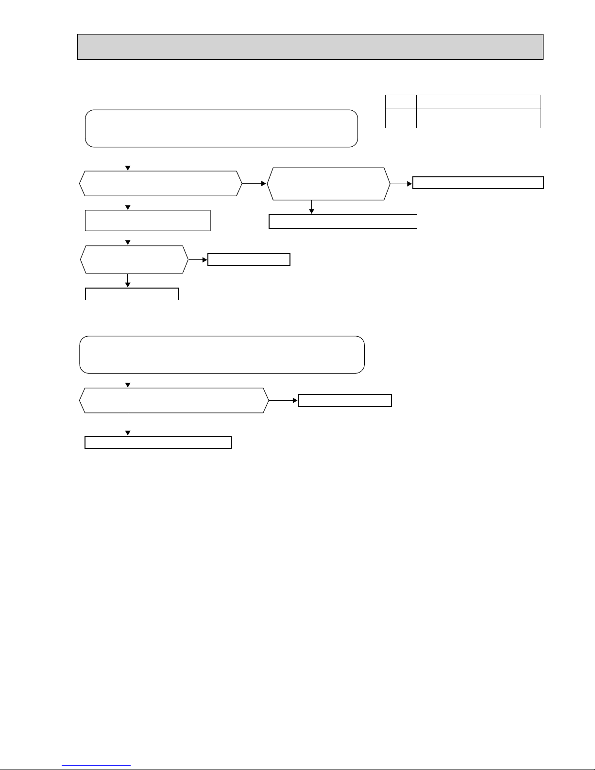
147
No
Yes
No
Yes
No
Yes
No
Yes
1. Disconnect the lead wire leading to the compressor.
2. 3 minutes after turning ON the power supply, start EMERGENCY
OPERATION in HEAT mode.
Is there voltage of 230 VAC between pin 1
and pin 2 at connector CN712?
Turn OFF the power supply.
Disconnect the connector CN712.
Replace the 4-way valve.
Replace the outdoor control P.C. board.
Replace the R.V. coil.
Is there voltage 230 VAC
between the pin 1 and pin 3 at
connector CN711?
Replace the noise filter P.C. board.
Is there normal resistance
to R.V. coil? (Refer to 11-5.)
1. Disconnect the lead wire leading to the compressor.
2. 3 minutes after turning ON the power supply, start EMERGENCY
OPERATION in COOL mode.
Is there voltage of 230 VAC between pin1 and
pin 2 at connector CN712?
Replace the 4-way valve.
Replace the outdoor control P.C. board.
:KHQKHDWLQJRSHUDWLRQGRHVQRWRSHUDWH
:KHQFRROLQJRSHUDWLRQGRHVQRWRSHUDWH
MXZ-3D54VA/3D54VA2/3D68VA/4D72VA
CN711
CN712
Outdoor control P.C. board
MXZ-3D54VA/3D54VA2/3D68VA/4D72VA
OBH626H

148
No
Yes
No
Yes
No
Yes
No
Yes
No
Yes
1. Disconnect the lead wire leading to the compressor.
2. 3 minutes after turning ON the power supply, start EMERGENCY
OPERATION in HEAT mode.
Is there voltage of 230 VAC between pin1 and
pin 2 at connector CN912?
Turn OFF the power supply of the indoor and the
outdoor unit.
1. Turn OFF the power supply of the indoor and the outdoor unit,
and disconnect the connector CN781.
2. 3 minutes after turning ON the power supply, start
EMERGENCY OPERATION in HEAT mode.
Replace the 4-way valve.
Replace the noise filter P.C. board.
Replace the R.V. coil.
Is there voltage 12 VDC
between the connector
CN781 pin 5 (+) and pin 3 (-)?
Replace the electronic
control P.C. board.
Disconnect the connector
CN912. Is there normal
resistance to R.V. coil?
(Refer to 11-5.)
1. Disconnect the lead wire leading to the compressor.
2. 3 minutes after turning ON the power supply, start EMERGENCY
OPERATION in COOL mode.
Is there voltage of 230 VAC between pin1 and
pin 2 at connector CN912?
1. Turn OFF the power supply of the indoor and the outdoor
unit, and disconnect the connector CN781.
2. 3 minutes after turning ON the power supply, start
EMERGENCY OPERATION in COOL mode.
Replace the 4-way valve.
Replace the noise filter P.C. board.
Is there voltage 12 VDC
between the connector CN781
pin 5 (+) and pin 3 (-)?
Replace the outdoor control P.C. board.
If the connector CN912 is not connected or R.V. coil is open, voltage
occurs between terminals even when the control is OFF.
:KHQKHDWLQJRSHUDWLRQGRHVQRWRSHUDWH
:KHQFRROLQJRSHUDWLRQGRHVQRWRSHUDWH
MXZ-4D83VA/5D102VA
MXZ-4D83VA/5D102VA
CN921 Noise fi lter P.C. board
OBH626H

149
MXZ-6D122VA
No
Yes
No
Yes
No
Yes
No
Yes
1. Disconnect the lead wire leading to the compressor.
2. 3 minutes after turning ON the power supply, start EMERGENCY
OPERATION in COOL mode.
Is there voltage of 230 VAC between pin 1
and pin 2 at connector CN712?
Turn OFF the power supply.
Disconnect the connector CNAC2.
Replace the 4-way valve.
Replace the outdoor
control P.C. board.
Replace the R.V. coil.
Is there voltage 230 VAC
between the pin 1 and pin 3 at
connector CNAC?
Replace the outdoor
power P.C. board.
Is there normal resistance
to R.V. coil? (Refer to 11-5.)
1. Disconnect the lead wire leading to the compressor.
2. 3 minutes after turning ON the power supply, start EMERGENCY
OPERATION in HEAT mode.
Is there voltage of 230 VAC between pin1
and pin 2 at connector CN712?
Replace the 4-way valve.
Replace the outdoor control P.C. board.
:KHQFRROLQJRSHUDWLRQGRHVQRWZRUN
:KHQKHDWLQJRSHUDWLRQGRHVQRWZRUN
CNAC
CN712
Outdoor control
P.C. board
CNAC2
Outdoor power
P.C. board
OBH626H
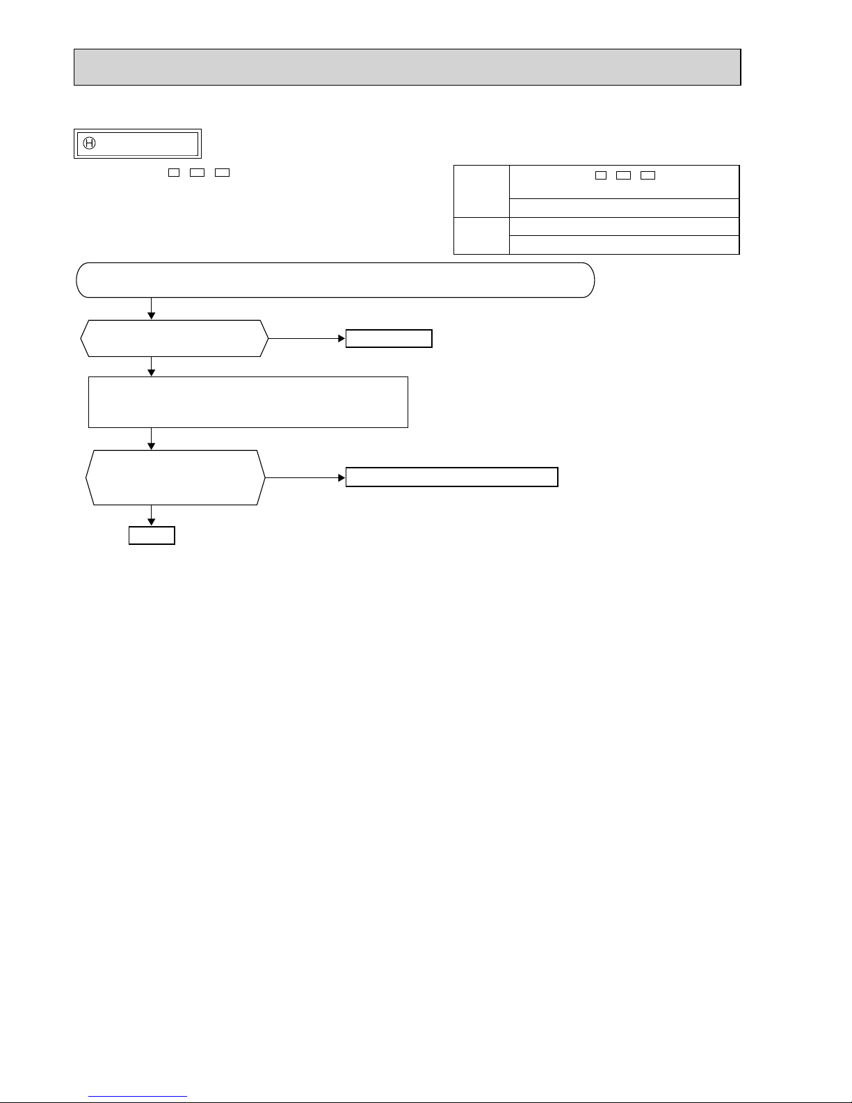
150
Check of HPS
Infinity
Yes
No
1. Disconnect the connector CN681/CN63H.
2. Check the resistance of HPS 1 minute after the outdoor unit breaker was turned OFF.
Check the resistance between
each terminal.
Reconnect CN681.
Turn ON the power supply to the indoor and the outdoor units.
3 minutes later, start EMERGENCY OPERATION.
Is HPS protection displayed
immediately after compressor
starts?
Replace HPS.
Replace the outdoor control P.C. board.
Normal
• When the operation frequency does not go up from lowest frequency.
MXZ-3D54VA2-E3,
ER3, ET3
MXZ-3D68VA/4D72VA/4D83VA/5D102VA/6D122VA
CN681
MXZ-3D54VA2-
E3
,
ER3, ET3
MXZ-3D68VA/4D72VA/4D83VA/5D102VA
Outdoor control P.C. board
CN63H
MXZ-6D122VA
Outdoor control P.C. board
OBH626H

151
Check of bus-bar voltage
•Check the voltage of power supply.
•Confi rm outdoor unit failure mode
recall function. (Refer to 11-2.2.)
Blink 5 times
Confi rm LED1 indication lamp on the
outdoor control P.C. board.
Replace the outdoor power
P.C. board.
Blink 9 times
Replace the outdoor
control P.C. board.
Turn OFF the power supply before removing P.C. board.
Confi rm LED1 indication lamp
on the outdoor control P.C.
board.
Turn ON the power supply.
Start operation.
Blink 6 times
Replace the outdoor control
P.C. board.
Lighting
Replace the outdoor control
P.C. board.
Blink 9 times
Replace the outdoor power
P.C. board.
Confi rm LED1 indication lamp
on the outdoor control P.C.
board.
Turn ON the power supply.
Start operation.
Normal
Lighting Lighting
MXZ-3D54VA/3D54VA2/3D68VA/4D72VA
MXZ-4D83VA/5D102VA
MXZ-6D122VA
•Check the voltage of power supply.
•Confi rm outdoor unit failure mode
recall function. (Refer to 11-2.2.)
Blink 5 times
Confi rm LED1 indication lamp on the
outdoor control P.C. board.
Replace the outdoor power
P.C. board.
Blink 9 times
Replace the outdoor control
P.C. board.
Turn OFF the power supply before removing P.C. board.
Confi rm LED1 indication lamp
on the outdoor control P.C.
board.
Turn ON power supply. Start
operation.
Lighting
Replace the outdoor control
P.C. board.
Blink 9 times
Replace the outdoor power
P.C. board.
Confi rm LED1 indication lamp
on the outdoor control P.C.
board.
Turn ON power supply. Start
operation.
Normal
Lighting Lighting
OBH626H

152
The other cases
Indoor unit does not operate. (different operating models in multi system)
• When you try to run two indoor units simultaneously, one for cooling and the other for heating, the unit which transmits signal
to the outdoor unit first decides the operation mode.
• When the above situation occurs, set all the indoor units to the same mode, turn OFF the indoor units, then turn them back
ON.
• Though the top of the indoor unit sometimes gets warm, this does not mean malfunction.
The reason is that the refrigerant gas continuously flows into the indoor unit even while it is not operating.
Check of outdoor refrigerant circuit
Has the operation stopped
during pump down?
Was the operation started with
the stop valve closed, and was
it opened during operation?
No
Yes
The operation has stopped to prevent the diesel explosion caused by
air trapped in the refrigerant circuit.
Close the stop valve, and disconnect
the power plug or turn the power supply OFF.
The unit occasionally stops when the
stop valve is opened or closed during
operation. Open the stop valve and
start the cooling operation again.
Yes
No
The refrigerant gas amount may be
60% or less than the normal amount.
Identify where the gas is leaking from,
and fi x the leak.
CAUTION : Do not start the opera-
tion again to prevent
hazards.
OBH626H

Copyright 2012 MITSUBISHI ELECTRIC CORPORATION
Distributed in Apr. 2015. No.OBH626 REVISED EDITION-H
Distributed in Jan. 2015. No.OBH626 REVISED EDITION-G
Distributed in Aug. 2014. No.OBH626 REVISED EDITION-F
Distributed in Apr. 2014. No.OBH626 REVISED EDITION-E
Distributed in Jan. 2014. No.OBH626 REVISED EDITION-D
Distributed in Oct. 2013. No.OBH626 REVISED EDITION-C
Distributed in Jan. 2013. No.OBH626 REVISED EDITION-B
Distributed in Dec. 2012. No.OBH626 REVISED EDITION-A
Distributed in Nov. 2012. No.OBH626
Made in Japan
New publication, effective Apr. 2015
Specifications are subject to change without notice.
HEAD OFFICE: TOKYO BLDG., 2-7-3, MARUNOUCHI, CHIYODA-KU, TOKYO 100-8310, JAPAN
 Loading...