

Mitsubishi MUZ-GL09NA-U8, MUZ-GL09NAH-U8, MUY-GL09NA-U1, MUZ-GL09NAH-U1, MUZ-GL12NA-U1 Service Manual
...
HFC
utilized
R410A
INDOOR UNIT
OUTDOOR UNIT
SERVICE MANUAL
Models
Revision D:
• MUZ-GL24NAH-U1 has been added.
OBH733 REVISED EDITION-C is void.
No. OBH733
REVISED EDITION-D
MUZ-GL09NA MUZ-GL09NA MUZ-GL12NA MUZ-GL15NA MUZ-GL18NA MUZ-GL24NA -
U1
MUZ-GL09NAH -
U8
MUZ-GL09NAH -
U1
MUZ-GL12NAH -
U1
MUZ-GL15NAH -
U1
MUZ-GL18NAH -
U1
MUZ-GL24NAH -
CONTENTS
1. TECHNICAL CHANGES ··································· 2
2. PART NAMES AND FUNCTIONS ····················· 3
3. SPECIFICATION ················································ 4
4. OUTLINES AND DIMENSIONS ························ 7
5. WIRING DIAGRAM ············································ 9
6. REFRIGERANT SYSTEM DIAGRAM ············· 21
7. DATA ································································ 25
8. ACTUA TOR CONTROL ··································· 39
9. SERVICE FUNCTIONS ··································· 40
10. TROUBLESHOOTING ····································· 41
11. DISASSEMBLY INSTRUCTIONS ···················· 64
U1
MUY-GL09NA -
U8
U1
MUY-GL12NA -
U1
MUY-GL15NA -
U1
MUY-GL18NA -
U1
MUY-GL24NA -
Indoor unit service manual
MSZ-GL•NA, MSY-GL•NA Series (OBH732)
U1
U1
U1
U1
U1
MUZ-GL18/24NA
MUZ-GL18/24NAH
MUY-GL18/24NA
NOTE:
RoHS compliant products have <G> mark on the spec name plate.
PARTS CATALOG (OBB733)
Use the specifi ed refrigerant only
OBH733D
Never use any refrigerant other than that specified.
Doing so may cause a burst, an explosion, or fire when the unit is being used, serviced, or disposed of.
Correct refrigerant is specified in the manuals and on the spec labels provided with our products.
We will not be held responsible for mechanical failure, system malfunction, unit breakdown or accidents caused by
failure to follow the instructions.
Revision A:
• MUZ-GL12/15NA-U1, MUZ-GL12/15NAH-U1 and MUY-GL09/12/15NA-U1 have been added.
Revision B:
• MUZ-GL09NA-U8 and MUZ-GL09NAH-U8 have been added.
Revision C:
U1
and
• MUZ-GL09NA-
MUZ-GL09NAH-
Revision D:
• MUZ-GL24NAH-U1 has been added.
1
MUZ-GL09NA
MUZ-GL09NA
MUZ-GL12NA
MUZ-GL15NA
MUZ-GL18NA
MUZ-GL24NA
1. New model
TECHNICAL CHANGES
U1
-
-
-
-
-
-
MUZ-GL09NAH
U8
MUZ-GL09NAH
U1
MUZ-GL12NAH
U1
MUZ-GL15NAH
U1
MUZ-GL18NAH
U1
MUZ-GL24NAH
U1
have been added.
U1
-
U8
-
U1
-
U1
-
U1
-
U1
-
MUY-GL09NA
MUY-GL12NA
MUY-GL15NA
MUY-GL18NA
MUY-GL24NA
U1
-
U1
-
U1
-
U1
-
U1
-
2
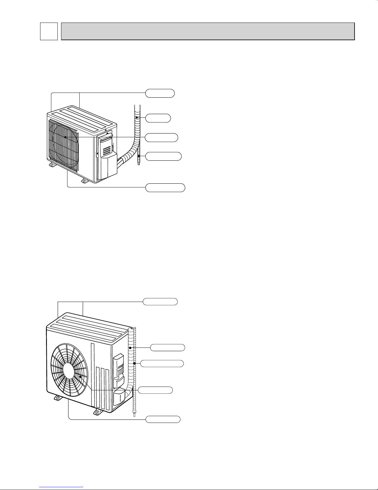
Piping
Air outlet
Drain outlet
Air inlet
(back and side)
Drain hose
2
OBH733D
PART NAMES AND FUNCTIONS
MUZ-GL09NA MUZ-GL09NAH MUY-GL09NA
MUZ-GL12NA MUZ-GL12NAH MUY-GL12NA
MUZ-GL15NA MUZ-GL15NAH MUY-GL15NA
Air inlet
(back and side)
Piping
Air outlet
Drain hose
Drain outlet
MUZ-GL18NA MUZ-GL18NAH MUY-GL18NA
MUZ-GL24NA MUZ-GL24NAH MUY-GL24NA
3
3
OBH733D
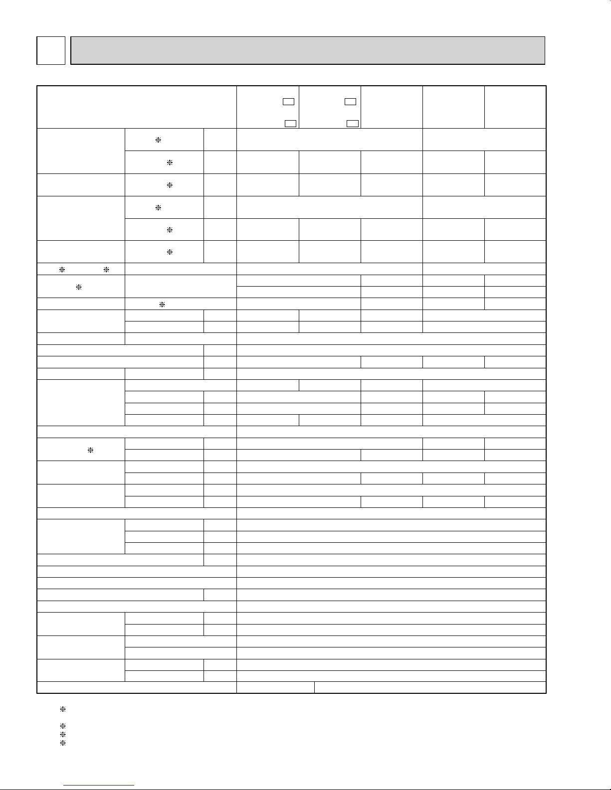
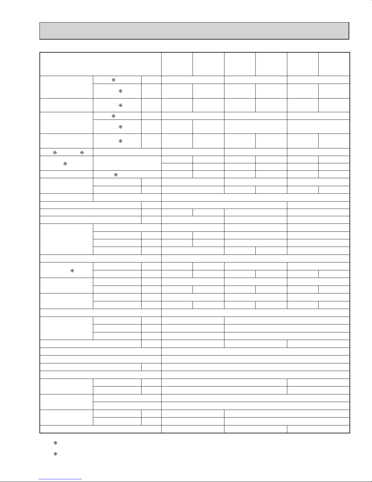
SPECIFICATION
Outdoor unit model
Capacity
Rated (Minimum~Maximum)
1
[SEER]
4
Capacity
Rated (Maximum)
Power consumption
Rated (Minimum~Maximum)
Power consumption
Rated (Maximum)
EER
HSPF IV
Cooling 1
Heating 47 1 (MUZ)
Heating 17 2 (MUZ)
Cooling 1
Heating 47 1 (MUZ)
Heating 17 2 (MUZ)
3
Cooling 15.4 [24.6] 13.0 [23.1]
Heating
(MUZ)
COP Heating 1
Power factor
Cooling (208/230)
(MUZ) (208/230)
Heating
(MUZ)
MUZ-
GL09NA-
MUZ-
GL09NAH-
U1
U1
MUZ-
GL09NA-
MUZ-
GL09NAH-
U8
MUY-
GL09NA
U8
Btu/h 9,000 (3,600 - 12,200)
Btu/h
Btu/h
10,900
(4,500 - 15,900)
6,700
(10,200)
10,900
(4,500 - 14,100)
7,000
(9,400)
-
-
W 585 (240 - 1,050) 920 (100 - 1,300)
W
W
720
(230 - 1,250)
630
(1,060)
NA: 12.8
NAH: 11.8
4.44
720
(230 - 1,070)
620
(790)
-
-
-
-
% 86/86 92/92 87/87 95/95
% 90/90 95/95
-
MUZ-
GL12NA
MUZ-
MUY-
GL12NA
GL12NAH
12,000 (1,500 - 13,600)
14,400
(2,000 - 18,100)
9,200
(12,000)
1,100
(110 - 1,620)
870
(1,240)
NA: 12.5
NAH: 11.5
3.84
96/96
Power supply V , phase , Hz 208/230, 1 , 60
Max. fuse size (time delay) A 15
Min. circuit ampacity A 9 7 9 7
Fan motor F.L.A A 0.50
Compressor
Model
R.L.A A 6.2 4.9 6.6 4.9
L.R.A A 7.7 6.1 8.2 6.1
Refrigeration oil
fl oz. (L) (Model)
KNB073FRVMC SNB092FQAMT KNB073FRVMC
9.1 (0.27)/(FV50S)
11.8 (0.35)/(FV50S)
9.1 (0.27)/(FV50S)
SNB092FQAMT
11.8 (0.35)/(FV50S)
Refrigerant control Linear expansion valve
Sound level 1
Airfl ow
High - Med. - Low
Fan speed
High - Med. - Low
Cooling dB(A) 48 49 49
Heating
(MUZ)
dB(A) 50
-
51
Cooling CFM 1,102 - 639
Heating
(MUZ)
CFM
1,186 - 1,116 - 1,045
-
1,186 - 1,116 - 1,045
Cooling rpm 810 - 490
Heating (MUZ) rpm
870 - 820 - 770
-
870 - 820 - 770
Defrost method Reverse cycle
W in. 31-1/2
Dimensions
D in. 11-1/4
H in. 21-5/8
Weight Ib. 81
External fi nish Munsell 3Y 7.8/1.1
Remote controller Wireless type
Control voltage
(by built-in transformer)
VDC 12 - 24
Refrigerant piping Not supplied
Refrigerant pipe size
(Min. wall thickness)
Connection method
Between the indoor
& outdoor units
Liquid in. 1/4 (0.0315)
Gas in. 3/8 (0.0315)
Indoor Flared
Outdoor Flared
Height difference ft. 40
Piping length ft. 65
Refrigerant charge (R410A) 2 lb. 5 oz. 2 lb. 9 oz.
NOTE: Test conditions are based on AHRI 210/240.
1: Rating conditions (Cooling) — Indoor: 80˚FDB, 67˚FWB, Outdoor: 95˚FDB, (75˚FWB)
(Heating) — Indoor: 70˚FDB, 60˚FWB, Outdoor: 47˚FDB, 43˚FWB
2: (Heating) — Indoor: 70˚FDB, 60˚FWB, Outdoor: 17˚FDB, 15˚FWB
3: Test condition (Refer to page 6.)
4: Test condition (Refer to page 6.)
4
-
-
-
-
-
-
-
-
-
-
Outdoor unit model
OBH733D
Capacity
Rated (Minimum~Maximum)
Capacity
Rated (Maximum)
Power consumption
Rated (Minimum~Maximum)
Power consumption
Rated (Maximum)
EER
HSPF IV
1
[SEER] 3 Cooling 13.0 [21.6] 13.4 [20.5] 12.5 [20.5]
4
Cooling 1
Heating 47 1 (MUZ)
Heating 17 2 (MUZ)
Cooling 1
Heating 47 1 (MUZ)
Heating 17 2 (MUZ)
Heating
(MUZ)
COP Heating 1
Power factor
Cooling (208/230)
(MUZ) (208/230)
Heating
(MUZ)
MUZ-
GL18NA
MUZ-
MUY-
GL18NA
GL18NAH
18,000 (5,800 ~ 22,000) 22,500 (8,200 ~ 31,400)
21,600
(5,400 ~ 25,000)
-
Btu/h
Btu/h
Btu/h
MUZ-
GL15NA
MUZ-
MUY-
GL15NA
GL15NAH
14,000 (3,100 - 18,200)
18,000
(4,800 - 20,900)
12,200
(16,400)
-
- 13,800 (18,200) - 16,000 (24,600)
W 1,080 (210 - 2,000) 1,295 (285 ~ 2,105) 1,742 (560 ~ 3,522)
W
W
1,600
(2,010)
1,190
(1,850)
NA: 11.7
NAH: 10.8
3.30
-
-
-
-
-
1,635 (275 ~ 2,455) 2,282 (508 ~ 3,592)
1,435
(2,105)
NA: 11.2
NAH: 10.2
3.77
-
-
-
% 97/97 99/99 99/99
% 98/98 99/99
-
MUZ-
GL24NA
MUZ-
GL24NAH
27,600
(7,500 ~ 36,900)
1,712
(3,232)
NA: 10.0
NAH: 10.0
3.46
99/99
Power supply V , phase , Hz 208/230, 1 , 60
Max. fuse size (time delay) A 15 20
Min. circuit ampacity A 10 9 14 17.1
Fan motor F.L.A 0.50 0.93 0.93
Model SNB130FQBMT SNB130FQBMT SNB172FQKMT
Compressor
R.L.A A 7.4 6.8 10 12.9
L.R.A A 9.3 8.5 12.5 16.1
Refrigeration oil
fl oz. (L) (Model)
11.8 (0.35)/(FV50S)
11.8 (0.35)/(FV50S) 11.8 (0.35)/(FV50S) 13.5 (0.40)/(FV50S)
Refrigerant control Linear expansion valve
Sound level 1
Airfl ow
High - Med. - Low
Fan speed
High - Med. - Low
Cooling dB(A) 49 49 54 55
Heating
(MUZ)
dB(A) 51
-
55
-
55
COOL CFM 1,102-639 1,742 - 922 2,016 - 1,769 - 890
HEAT CFM
1,186 - 1,045 - 1,045
-
1,691 - 1,691 - 1,372
-
1,701 - 1,701 - 1,341
Cooling rpm 810 - 490 840 - 450 950 - 840 - 450
Heating (MUZ) rpm
870 - 770 - 770
-
810 - 810 - 650
-
810 - 810 - 650
Defrost method Reverse cycle
W in. 31-1/2 33-1/16
Dimensions
D in. 11-1/4 13
H in. 21-5/8 34-5/8
Weight Ib. 81 121 119
External fi nish Munsell 3Y 7.8/1.1
Remote controller Wireless type
Control voltage
(by built-in transformer)
VDC 12 - 24
Refrigerant piping Not supplied
Refrigerant pipe size
(Min. wall thickness)
Connection method
Between the indoor
& outdoor units
Liquid in. 1/4 (0.0315) 3/8 (0.0315)
Gas in. 1/2 (0.0315) 5/8 (0.0315)
Indoor Flared
Outdoor Flared
Height difference ft. 40 50
Piping length ft. 65 100
Refrigerant charge (R410A) 2 lb. 9 oz. 3 lb. 9 oz. 4 lb. 3 oz.
NOTE: Test conditions are based on AHRI 210/240.
1: Rating conditions (Cooling) — Indoor: 80˚FDB, 67˚FWB, Outdoor: 95˚FDB, (75˚FWB)
(Heating) — Indoor: 70˚FDB, 60˚FWB, Outdoor: 47˚FDB, 43˚FWB
2: (Heating) — Indoor: 70˚FDB, 60˚FWB, Outdoor: 17˚FDB, 15˚FWB
5
MUY-
GL24NA
-
-
-
-
-
-
-
-
-
-

Test condition
OBH733D
3, 4
Mode Test
ARI
"A-2" Cooling Steady State
at rated compressor Speed
"B-2" Cooling Steady State
at rated compressor Speed
SEER
(Cooling)
HSPF
(Heating)
NOTE:
5
: At Intermediate compressor Speed
"B-1" Cooling Steady State
at minimum compressor Speed
"F-1" Cooling Steady State
at minimum compressor Speed
"E-V" Cooling Steady State
at Intermediate compressor Speed
"H1-2" Heating Steady State
at rated compressor Speed
"H3-2" Heating
at rated compressor Speed
"H0-1" Heating Steady State
at minimum compressor Speed
"H1-1" Heating Steady State
at minimum compressor Speed
"H2-V" Heating
at Intermediate compressor Speed
5
5
= ("Rated compressor speed" - "minimum compressor speed") / 3 + "minimum compressor speed".
Indoor air condition (°F) Outdoor air condition (°F)
Dry bulb Wet bulb Dry bulb Wet bulb
80 67 95 (75)
80 67 82 (65)
80 67 82 (65)
80 67 67 (53.5)
80 67 87 (69)
70 60 47 43
70 60 17 15
70 60 62 56.5
70 60 47 43
70 60 35 33
OPERATING RANGE
(1) POWER SUPPLY
Outdoor unit
(2) OPERATION
Mode Condition
Standard temperature 80 67 95 —
Cooling
Heating
Maximum temperature 90 73 115 —
Minimum temperature 67 57 14 —
Maximum humidity 78 % —
Standard temperature 70 60 47 43
Maximum temperature 80 67 75 65
Minimum temperature 70 60 -4 -5
Rated voltage Guaranteed voltage (V)
208/230 V
1 phase
60 Hz
Min. 187
Indoor Outdoor
DB WB DB WB
208 230 Max. 253
Intake air temperature (°F)
6
4
clear *1
*1
4 in. (100 mm) or more when
front and sides of the unit are clear
*2
When any 2 sides of left, right
and rear of the unit are clear
holes
(GL09/12/15NA)
(GL09/12/15NAH)
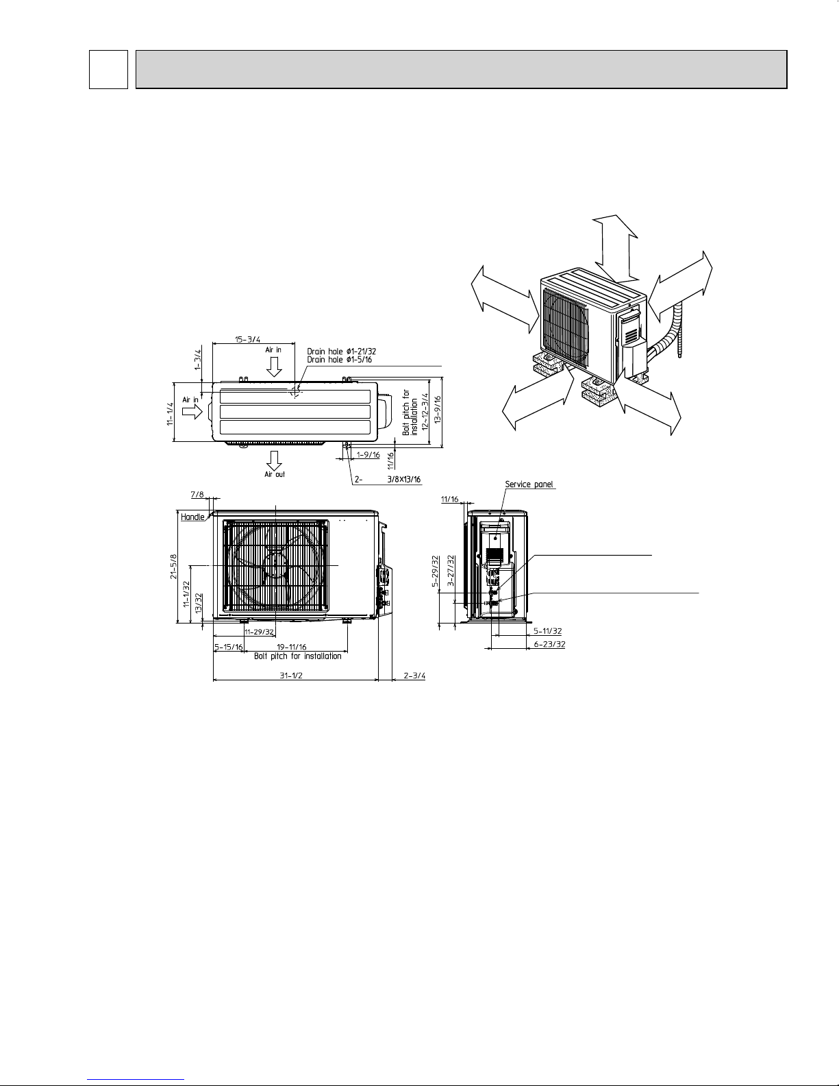
REQUIRED SPACE
Liquid refrigerant pipe joint
Refrigerant pipe (flared)
Ø 1/4
Gas refrigerant pipe joint
Refrigerant pipe (flared)
Ø 3/8 (GL09/12)
Ø 1/2 (GL15)
4 in. (100 mm)
or more
14 in. (350 mm)
or more
8 in. (200 mm)
or more *2
4 in. (100 mm)
or more
OBH733D
OUTLINES AND DIMENSIONS
MUZ-GL09NA MUZ-GL09NAH MUY-GL09NA
MUZ-GL12NA MUZ-GL12NAH MUY-GL12NA
MUZ-GL15NA MUZ-GL15NAH MUY-GL15NA
Unit: inch
7
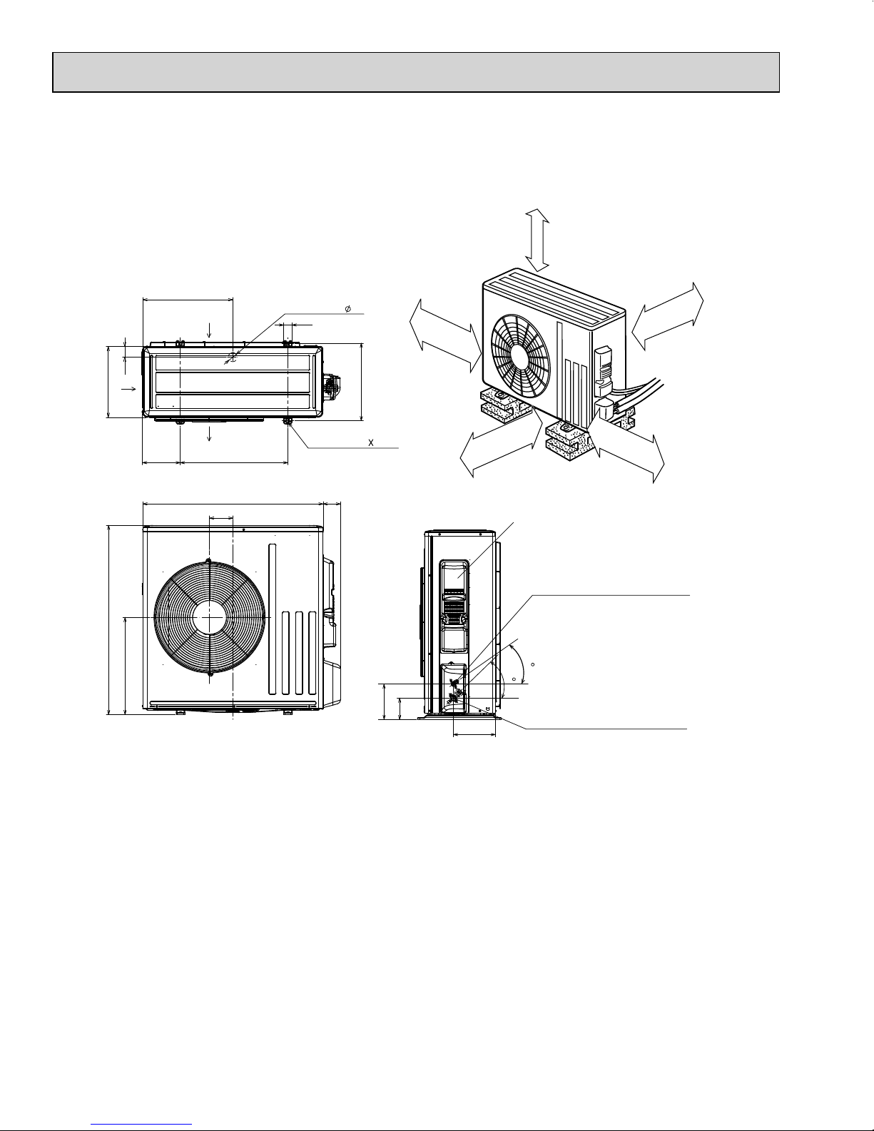
MUZ-GL18NA MUZ-GL18NAH MUY-GL18NA
OBH733D
MUZ-GL24NA MUZ-GL24NAH MUY-GL24NA
REQUIRED SPACE
Unit: inch
Air in
13
34-5/8
2
17-25/32
6-7/8
16-7/16
Air in
19-11/16
4-5/16
Air out
33-1/16
*1 20 in. (500 mm) or more when front
and sides of the unit are clear
Drain hole
1-9/16
1-5/8
14-3/16
2-holes 13/32 13/16
3-3/16
6-1/2
3-29/32
4 in. (100 mm)
or more
7-11/16
Clear *1
20 in. (500 mm)
or more *2
*2 When any 2 sides of left, right
and rear of the unit are clear
Service panel
Liquid refrigerant pipe joint
Refrigerant pipe (flared)
Refrigerant pipe (flared)
35
44
Gas refrigerant pipe joint
Refrigerant pipe (flared)
Refrigerant pipe (flared)
4 in. (100 mm)
or more
14 in. (350 mm)
or more
Ø 1/4 (GL18)
Ø 3/8 (GL24)
Ø 1/2 (GL18)
Ø 5/8 (GL24)
8

5
OBH733D
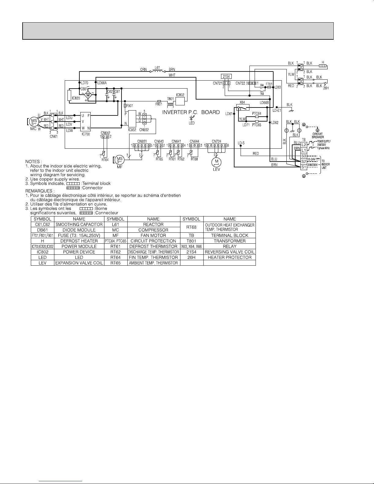
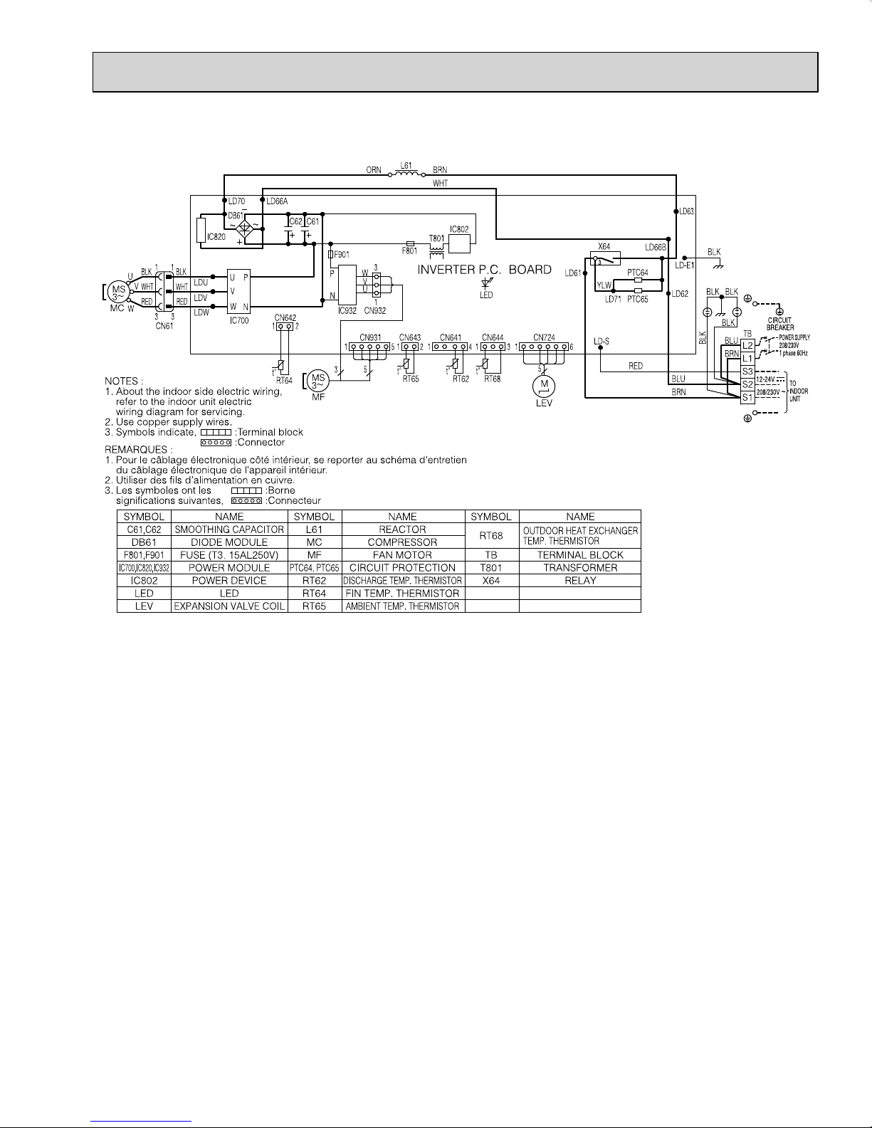
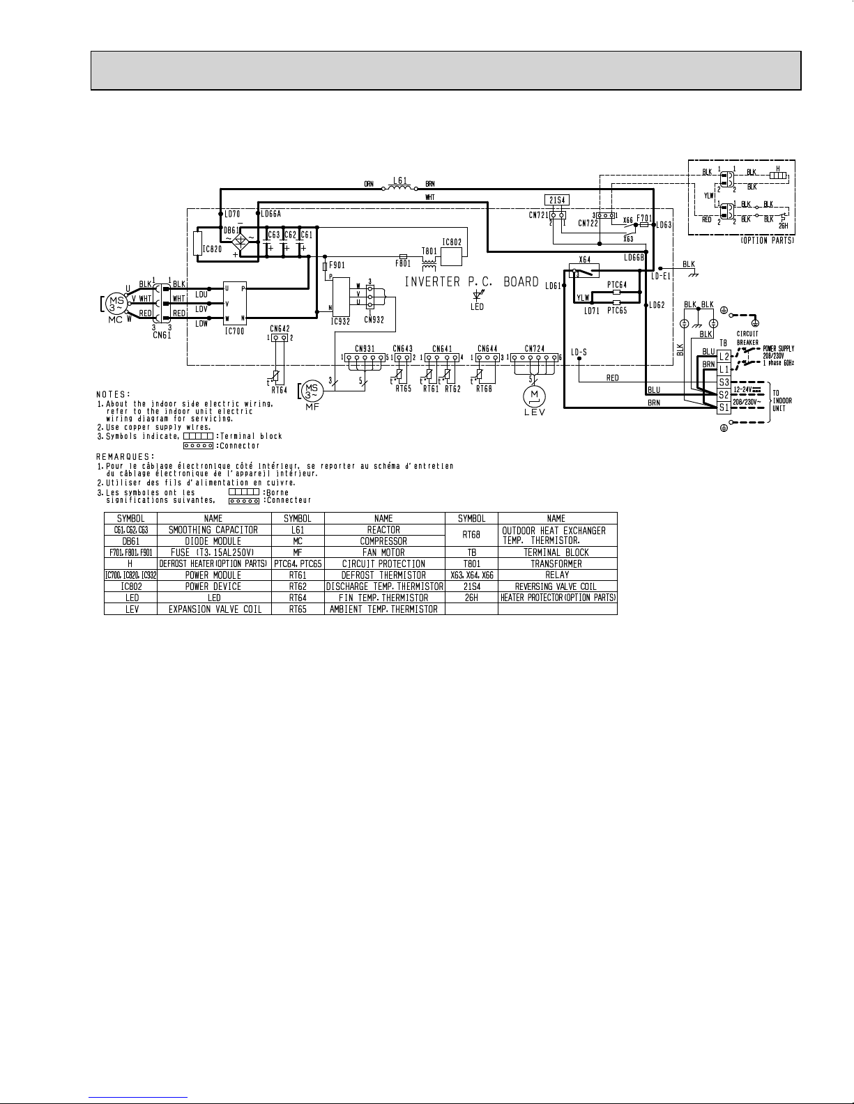
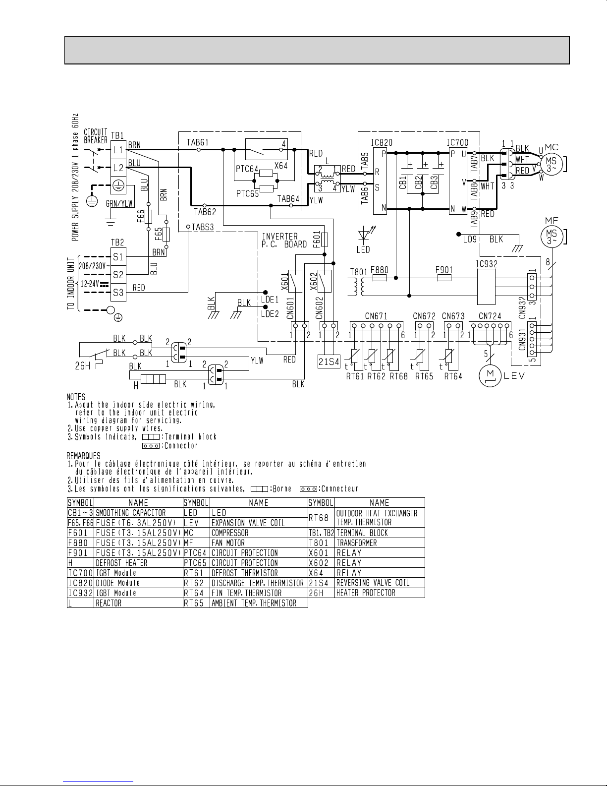
MUZ-GL09NA MUZ-GL12NA
WIRING DIAGRAM
9
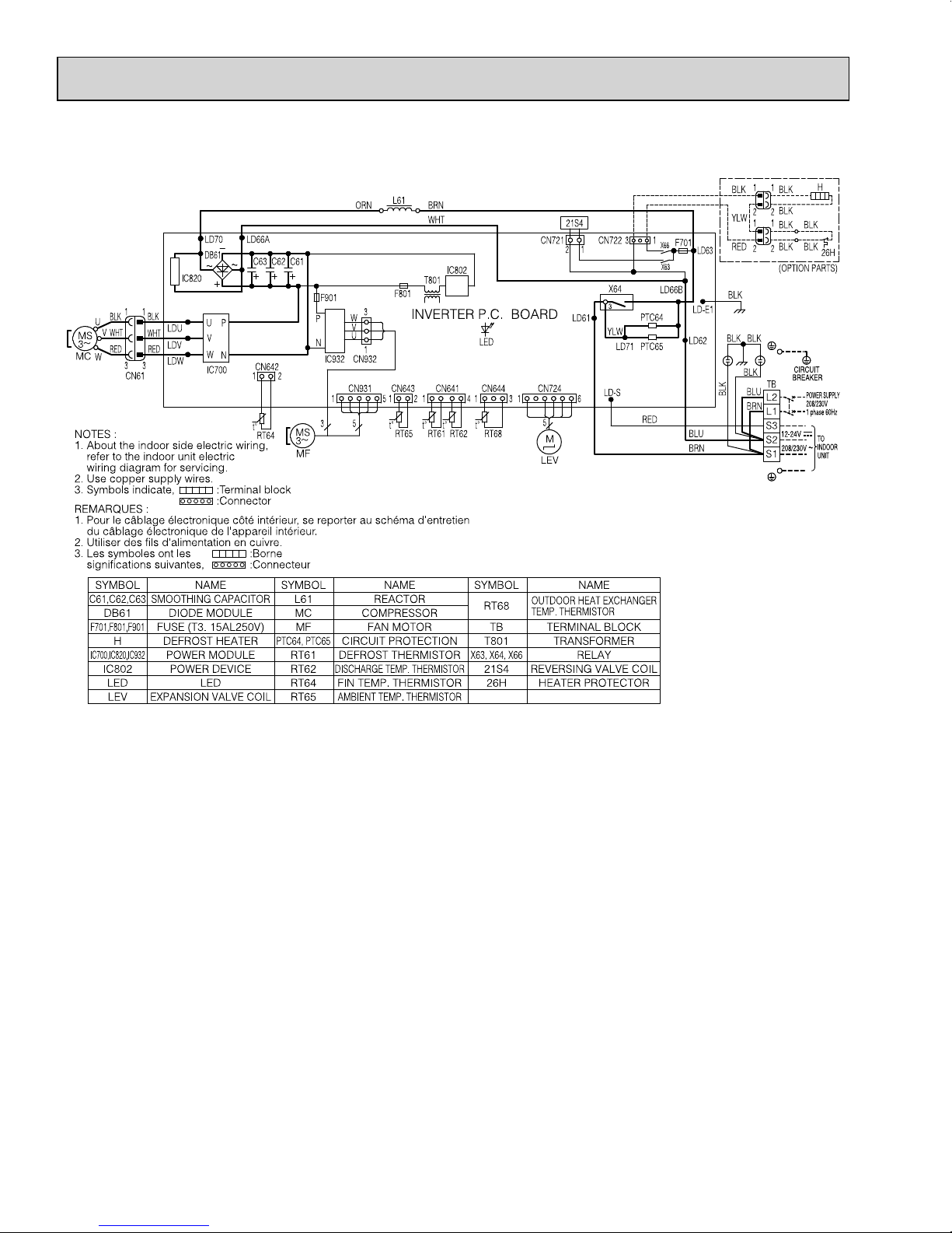
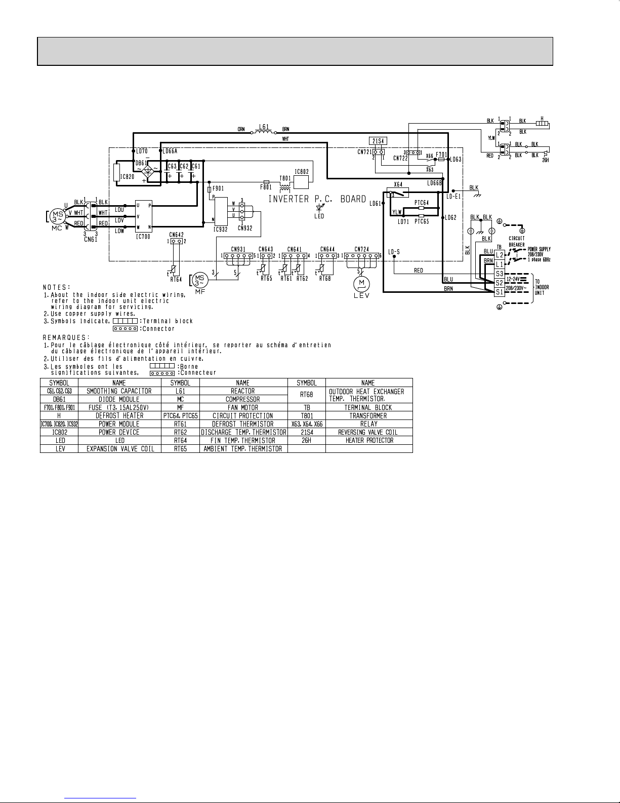
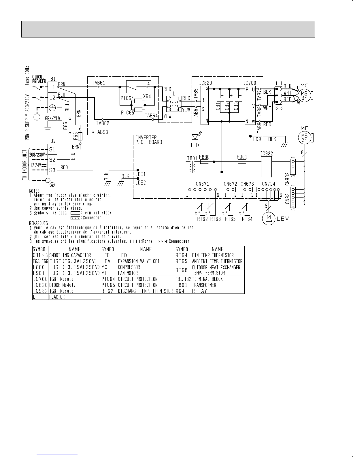
MUZ-GL09NAH MUZ-GL12NAH
OBH733D
10
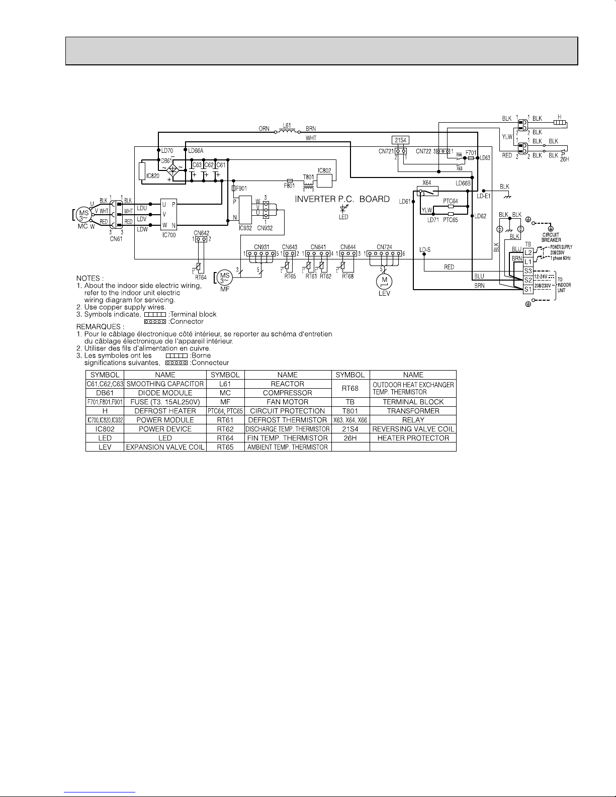
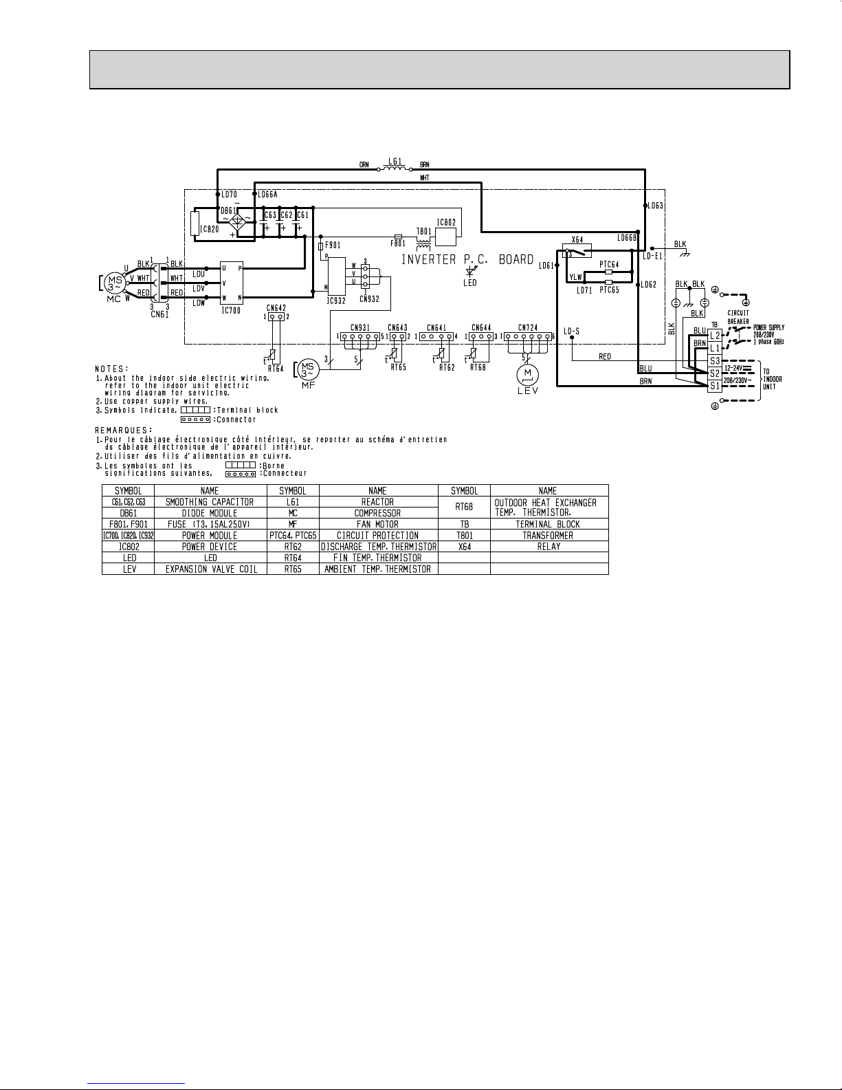
MUY-GL09NA MUY-GL12NA
OBH733D
11
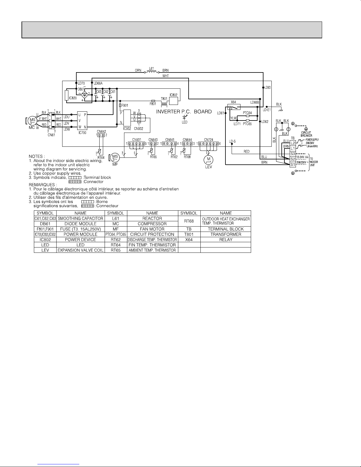
MUZ-GL15NA
OBH733D
12
MUZ-GL15NAH
OBH733D
13
MUY-GL15NA
OBH733D
14
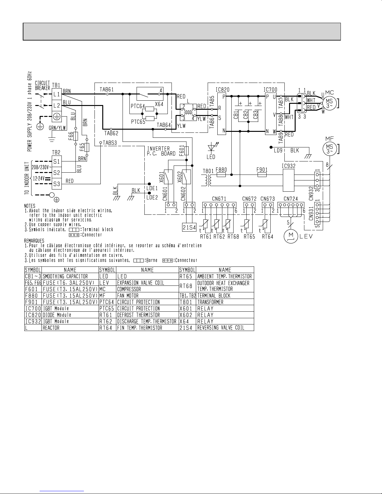
MUZ-GL18NA
OBH733D
15
MUZ-GL18NAH
OBH733D
16
MUY-GL18NA
OBH733D
17
MUZ-GL24NA
OBH733D
18
MUZ-GL24NAH
OBH733D
19
MUY-GL24NA
OBH733D
20
6
Outdoor
heat
exchanger
Flared connection
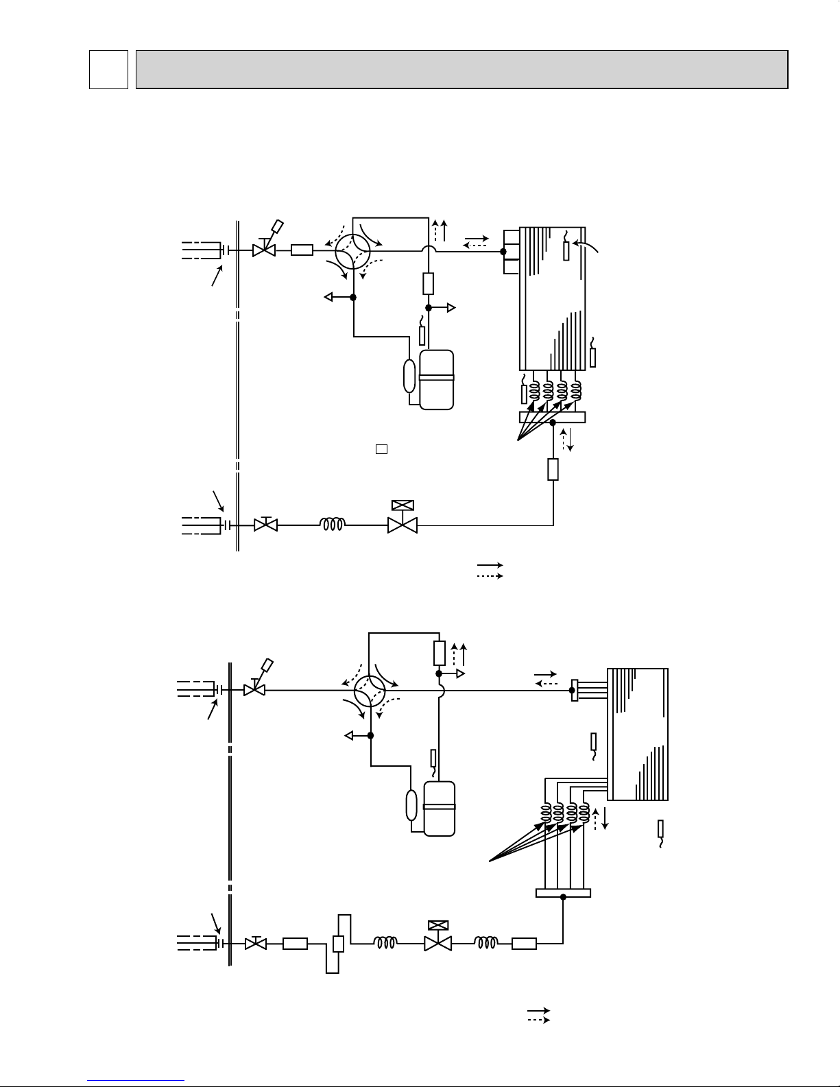
Defrost
thermistor
RT61
(MUZ)
Discharge
temperature
thermistor
RT62
Flared connection
Stop valve
(with strainar)
Refrigerant flow in cooling
Compressor
4-way valve
Refrigerant flow in heating (MUZ)
Refrigerant pipe ø1/4 (ø6.35)
(with heat insulator)
R.V. coil (MUZ)
heating ON
cooling OFF
Strainer
#100
LEV
Ambient
temperature
thermistor
RT65
Muffler
Capillary tube
O.D. 0.118 ×
I.D. 0.079 × 9-7/16
(ø3.0 × ø2.0 × 240)
(MUZ-GL09NA/H -
U1 )
Outdoor heat
exchanger
temperature
thermistor
RT68
Capillary tube
O.D. 0.118 ×
I.D. 0.079 × 8-9/32
(ø3.0 × ø2.0 × 210)
Service
port
Service
port
Refrigerant pipe ø3/8 (ø9.52) (GL09/12)
(with heat insulator)
ø1/2 (ø12.7) (GL15)
Stop valve
(with service port)
Capillary tube
O.D. 0.157 ×
I.D. 0.094 × 9-7/16
(ø4.0 × ø2.4 × 240)
(Other models
)
Muffler
OBH733D
REFRIGERANT SYSTEM DIAGRAM
MUZ-GL09NA MUZ-GL09NAH MUY-GL09NA
MUZ-GL12NA MUZ-GL12NAH MUY-GL12NA
MUZ-GL15NA MUZ-GL15NAH MUY-GL15NA
Unit: Inch (mm)
MUZ-GL18NA MUZ-GL18NAH MUY-GL18NA
ø1/2 (ø
ø1/4 (ø
12.7)
Stop valve
6.35)
Stop valve
(with service port)
Strainer
Refrigerant pipe
(with heat insulator)
Flared connection
Flared connection
Refrigerant pipe
(with heat insulator)
#100
4-way
valve
Discharge
Service
port
Muffler
temperature
thermistor
RT62
Compressor
Capillary tube
O.D. 0.157×
I.D. 0.094×
3-15/16
(ø
4.0×ø
2.4×100)
Muffler
with #100 mesh strainer
Service port
Capillary tube
O.D. 0.118×
I.D. 0.079× 7-7/8
(ø3.0×ø2.0×200(×4))
LEV
Capillary tube
O.D. 0.157×
I.D. 0.094×7-7/8
(ø
4.0×ø
Strainer
2.4×200)
21
#100
Outdoor
Defrost
thermistor
RT61
(MUZ)
Refrigerant flow in cooling
Refrigerant flow in heating (MUZ)
heat
exchanger
Outdoor heat
exchanger
temperature
thermistor
RT68
R.V. coil (MUZ)
heating ON
cooling OFF
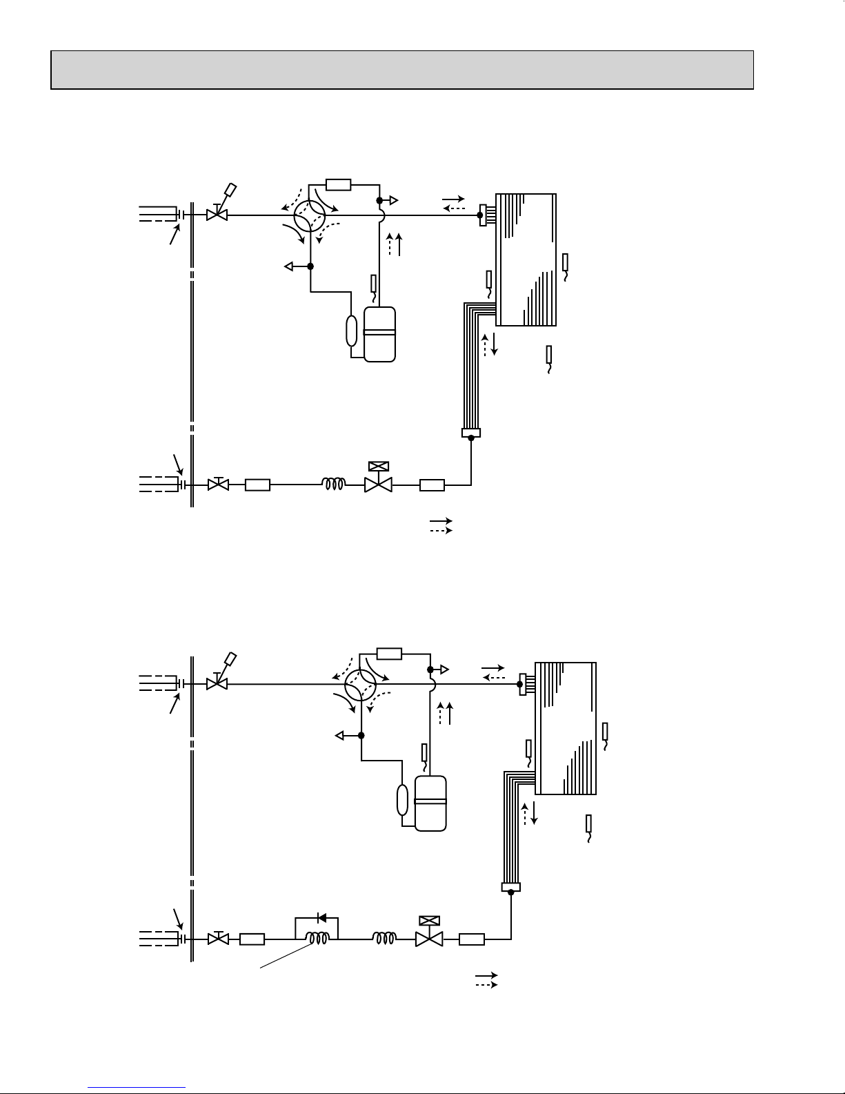
MUZ-GL24NA MUY-GL24NA
OBH733D
Refrigerant pipe
(with heat insulator)
Flared connection
Flared connection
Refrigerant pipe ø3/8 (
(with heat insulator)
ø
5/8 (
ø15.88)
Stop valve
(with service port)
Stop valve
ø9.52)
4-way valve
Strainer
#100
Service
port
Muffler
with #100 mesh strainer
Discharge
temperature
thermistor
RT62
Compressor
LEV
Capillary tube
O.D.0.157
×
3-15/16
(ø
4.0
×
ø
2.4×100)
×
I.D.0.094
Service port
Defrost
thermistor
RT61
(MUZ)
Strainer
#100
Outdoor
heat
exchanger
Outdoor heat
exchanger
temperature
thermistor
RT68
R.V. coil (MUZ)
heating ON
cooling OFF
Refrigerant flow in cooling
Refrigerant flow in heating (MUZ)
Ambient
temperature
thermistor
RT65
MUZ-GL24NAH
Refrigerant pipe
(with heat insulator)
Flared connection
Flared connection
Refrigerant pipe ø3/8
(with heat insulator)
ø
5/8 (
ø15.88)
Stop valve
(with service port)
Stop valve
(
ø9.52)
Strainer
#100
Capillary tube
O.D.0.118
×
21-21/32
(ø
3.0
×
ø
1.8×550)
×
4-way valve
Service
port
CHECK
VALVE
I.D.0.071
Muffler
#100
Discharge
temperature
thermistor
RT62
Compressor
Capillary tube
O.D.0.157
×
3-15/16
(ø
4.0
×
ø
2.4×100)
×
Service
port
LEV
I.D.0.094
Defrost
thermistor
RT61
Strainer
#100
Outdoor
heat
exchanger
Outdoor heat
exchanger
temperature
thermistor
RT68
R.V. coil
heating ON
cooling OFF
Refrigerant flow in cooling
Refrigerant flow in heating
Ambient
temperature
thermistor
RT65
22
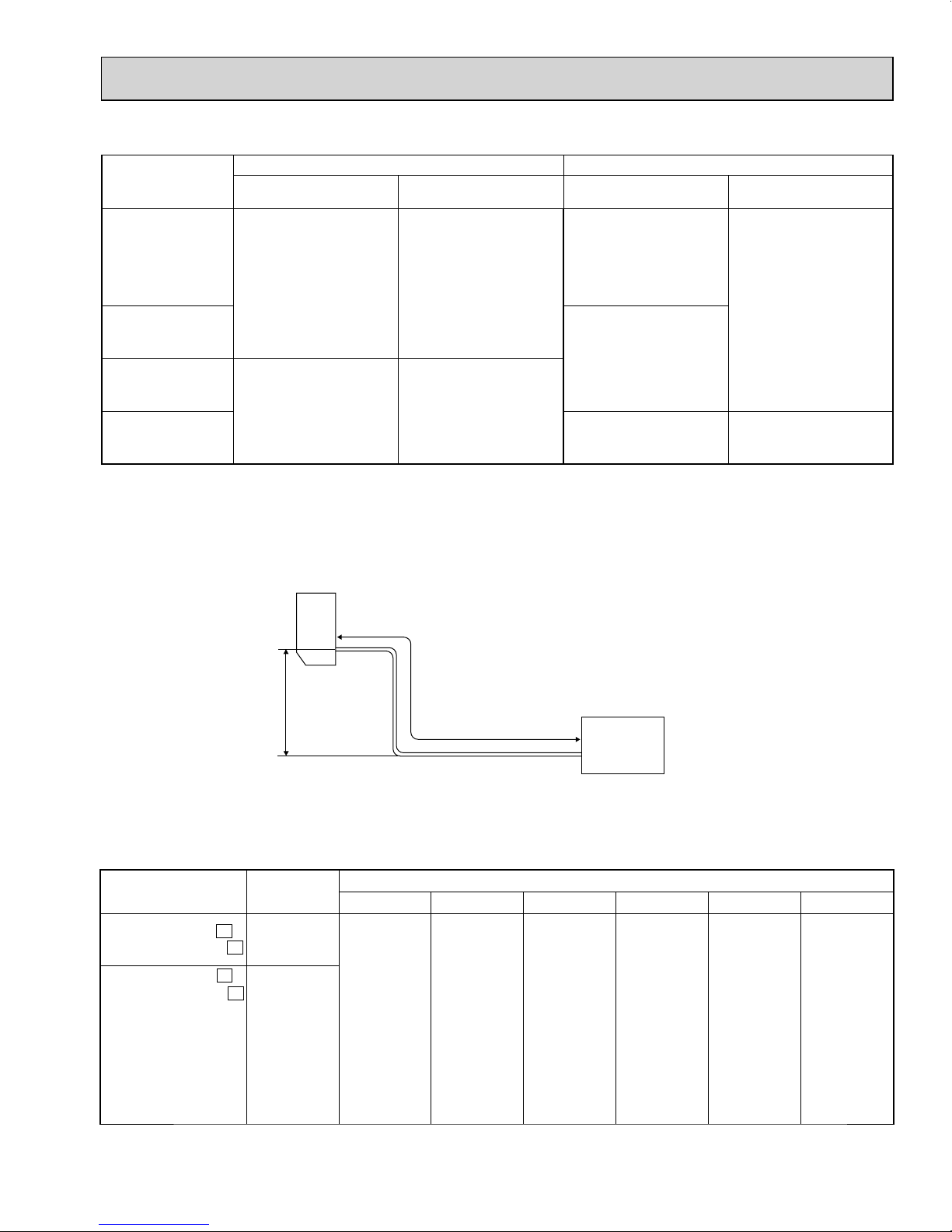
Max. Length
A
Max. Height
difference
B
Indoor
unit
Outdoor unit
MAX. REFRIGERANT PIPING LENGTH and MAX. HEIGHT DIFFERENCE
OBH733D
Refrigerant piping: ft. Piping size O.D: in.
Model
MUZ-GL09NA
MUZ-GL09NAH
MUY-GL09NA
MUZ-GL12NA
MUZ-GL12NAH
MUY-GL12NA
MUZ-GL15NA
MUZ-GL15NAH
MUY-GL15NA
MUZ-GL18NA
MUZ-GL18NAH
MUY-GL18NA
MUZ-GL24NA
MUZ-GL24NAH
MUY-GL24NA
Max. Length
Max. Height difference
A
65 40
100 50
B
Gas Liquid
3/8
1/2
5/8 3/8
1/4
ADDITIONAL REFRIGERANT CHARGE (R410A: oz.)
NOTE: Refrigerant piping exceeding 25 ft. requires additional refrigerant charge according to the calculation.
U1
U1
U8
U8
Outdoor unit
precharged
2 lb. 5 oz.
2 lb. 9 oz.
Model
MUZ-GL09NA MUZ-GL09NAH -
MUZ-GL09NA MUZ-GL09NAH MUY-GL09NA
MUZ-GL12NA
MUZ-GL12NAH
MUY-GL12NA
MUZ-GL15NA
MUZ-GL15NAH
MUY-GL15NA
Refrigerant piping length (one way): ft.
25 30 40 50 60 65
0 1.08 3.24 5.40 7.56 8.64
Calculation: X oz. = 1.08/5 oz./ft. × (Refrigerant piping length (ft.) - 25)
23
 Loading...