

Mitsubishi Electric MUZ-GE35VA, MUZ-GE25VA, MUZ-GE42VA, MUZ-GE42VAH, MUZ-GEVAH Service Manual
...
SERVICE MANUAL
CONTENTS
1. TECHNICAL CHANGES ···································3
2. PART NAMES AND FUNCTIONS ····················· 4
3. SPECIFICATION ················································ 5
4. NOISE CRITERIA CURVES ······························ 7
5. OUTLINES AND DIMENSIONS ························ 9
6. WIRING DIAGRAM ···········································11
7. REFRIGERANT SYSTEM DIAGRAM ············· 18
8. PERFORMANCE CURVES ····························· 21
9. ACTUA TOR CONTROL ··································· 40
10. SERVICE FUNCTIONS ···································· 41
11. TROUBLESHOOTING ····································· 41
12. DISASSEMBLY INSTRUCTIONS ···················· 61
Models
SPLIT-TYPE AIR CONDITIONERS
NOTE:
RoHS compliant products have <G> mark on the spec name plate.
HFC
utilized
R410A
No. OBH516
REVISED EDITION-C
OUTDOOR UNIT
Indoor unit service manual
MSZ-GE•VA Series (OBH515)
MSZ-CGE•VA Series (OBH523)
PARTS CATALOG (OBB516)
MUZ-GE25VA
MUZ-GE35VA
MUZ-GE42VA
Revision C:
• The compressor winding resistance for
MUZ-GE71VA - E1 has been changed.
Please void OBH516 REVISED EDITION-B.
MUZ-GE25VA -
E1
MUZ-GE50VA -
E1
MUZ-GE25VAH -
E1
MUZ-GE50VAH -
E1
MUZ-GE35VA -
E1
MUZ-GE60VA -
E1
MUZ-GE35VAH -
E1
MUZ-GE71VA -
E1
MUZ-GE42VA -
E1
MUZ-GE42VAH -
E1

2
Revision A:
• MUZ-GE42VA -
E1
, MUZ-GE42VAH - E1, MUZ-GE50VA - E1 and MUZ-GE50VAH - E1 have been added.
Revision B:
• MUZ-GE60VA - E1 and MUZ-GE71VA - E1 have been added.
Revision C:
• The compressor winding resistance for MUZ-GE71VA -
E1
has been changed.

3
MUZ-GE25VA -
E1
MUZ-GE25VAH -
E1
MUZ-GE35VA -
E1
MUZ-GE35VAH -
E1
MUZ-GE42VA -
E1
MUZ-GE42VAH -
E1
MUZ-GE50VA -
E1
MUZ-GE50VAH -
E1
MUZ-GE60VA -
E1
MUZ-GE71VA -
E1
1. New model
TECHNICAL CHANGES
1
4
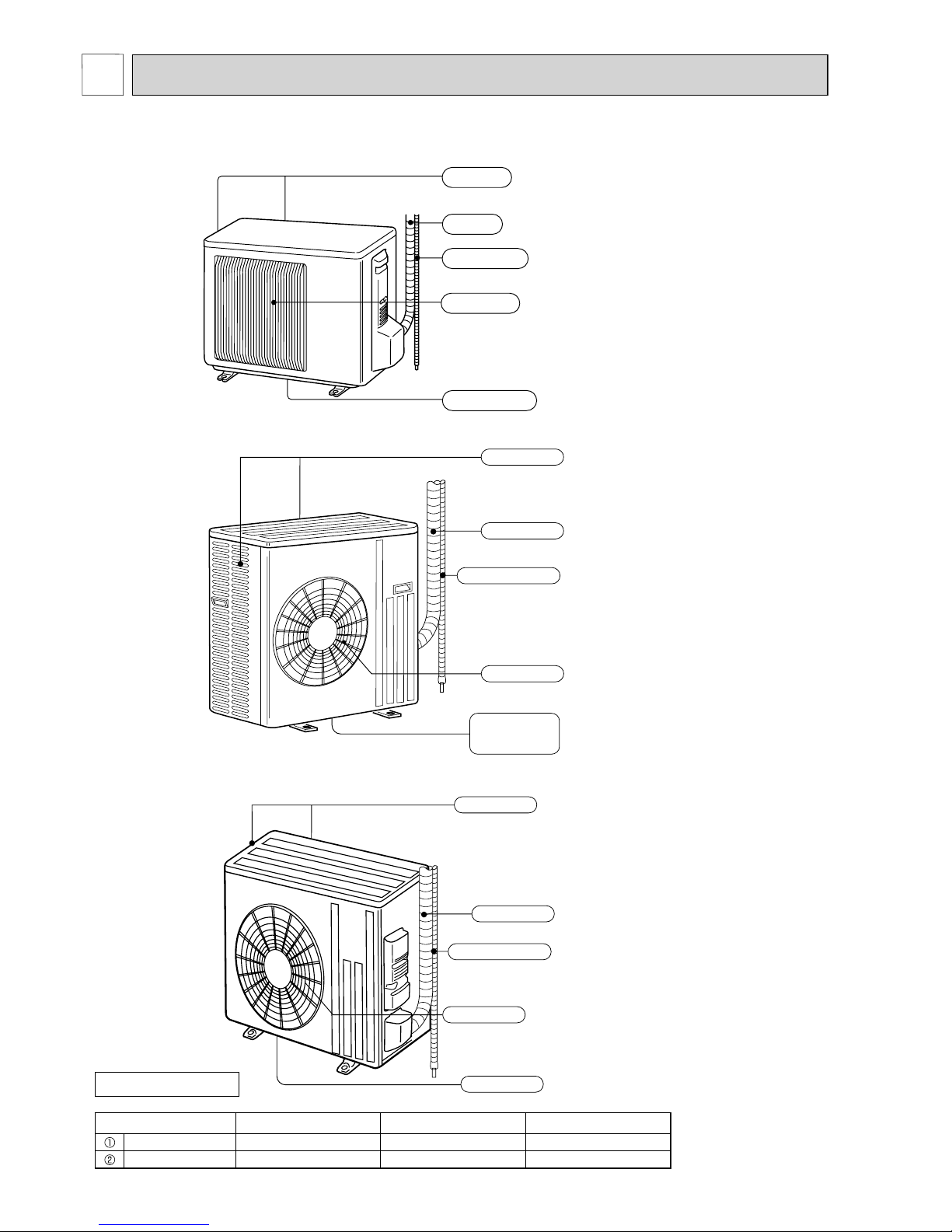
Air outlet
Drain outlet
Piping
Drain hose
Air inlet
(back and side)
MUZ-GE25VA MUZ-GE25VAH MUZ-GE35VA MUZ-GE35VAH
MUZ-GE42VA MUZ-GE42VAH
MUZ-GE50VA MUZ-GE50VAH
Piping
Air outlet
Air inlet
(back and side)
Drain hose
Drain outlet
(GE50VA)
PART NAMES AND FUNCTIONS
2
ACCESSORIES
Model MUZ-GE25/35/42VA MUZ-GE50VA MUZ-GE60/71VA
Drain socket 1 1 1
Drain cap - 2 -
MUZ-GE60VA MUZ-GE71VA
Piping
Air outlet
Drain outlet
Air inlet
(back and side)
Drain hose
5
Outdoor model
MUZ-
GE25VA
MUZ-
GE25VAH
MUZ-
GE35VA
MUZ-
GE35VAH
MUZ-
GE42VA
MUZ-
GE42VAH
MUZ-
GE50VA
MUZ-
GE50VAH
MUZ-
GE60VA
MUZ-
GE71VA
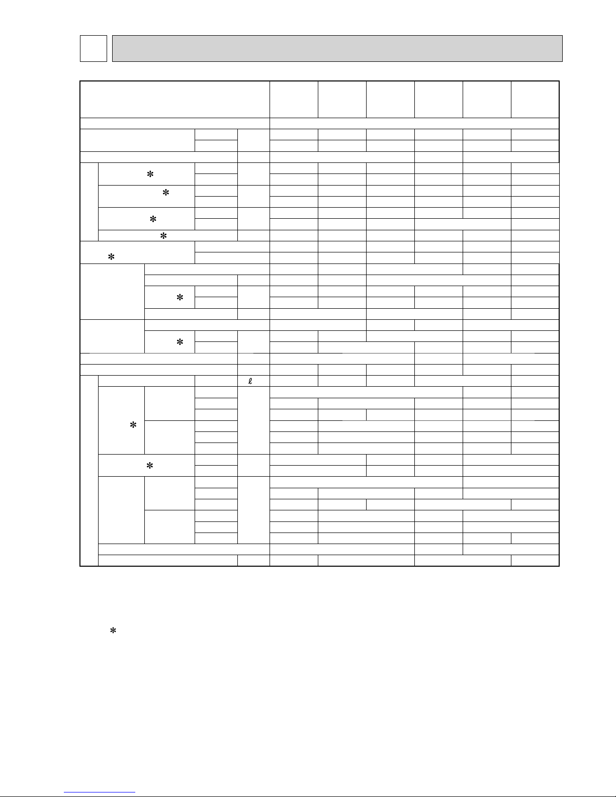
Power supply Single phase, 230 V, 50 Hz
Capacity
Rated frequency (Min.-Max.)
Cooling
kW
2.5 (1.1 - 3.5) 3.5 (1.1 - 4.0) 4.2 (0.9 - 4.8) 5.0 (1.4 - 5.5) 6.0 (1.5 - 7.5) 7.1 (2.4 - 8.7)
Heating
3.2 (1.3 - 4.5) 4.0 (1.6 - 5.3) 5.4 (1.4 - 6.0) 5.8 (1.4 - 7.3) 6.8 (2.0 - 9.3) 8.1 (2.2 - 9.9)
Breaker Capacity A 10 16 20
Electrical data
Power input 1 (Total)
Cooling
W
545 865 1,215 1,515 1,760 2,130
Heating 700 955 1,460 1,565 1,770 2,110
Running current
1
(Total)
Cooling
A
2.9 4.2 5.6 6.8 7.8 9.3
Heating 3.7 4.6 6.6 7.0 7.9 9.4
Power factor 1 (Total)
Cooling
%
82 90 94 96 98 99
Heating 82 90 96 97 98
Starting current 1 (Total) A 3.7 4.6 6.6 7.0 7.9 9.4
Coeffi cient of performance
(COP)
1 (Total)
Cooling 4.59 4.05 3.46 3.30 3.40 3.33
Heating 4.57 4.19 3.70 3.71 3.84 3.83
Compressor
Model
KNB073FFDHC KNB092FFAHC
SNB130FGBHT
SNB130FGBMT SNB172FEKMT
Output W 550 650 900 1,200
Current 1
Cooling
A
2.44 3.56 4.99 6.09 6.59 8.00
Heating 3.20 4.06 5.98 6.32 6.44 8.07
Refrigeration oil (Model) cc 320 (NEO22) 450 (NEO22)
350(FV50S) 400(FV50S)
Fan motor
Model RC0J50-DB RC0J50-EA RC0J60-AA RC0J60-BC
Current 1
Cooling
A
0.24 0.35 0.32 0.84 0.83
Heating 0.27 0.31 0.32 0.93 0.82
Dimensions W × H × D mm 800 × 550 × 285
840 × 850 × 330
840 × 880 × 330
Weight kg 30 33 36 54 50 53
Special remarks
Dehumidifi cation Cooling /h 0.2 0.9 1.4 1.8 2.3
Air fl ow 1
Cooling
High
m3/h
- 3,492 3,426
Med. 1,806 1,872 2,940 3,066 3,006
Low 1,170 1,776 1,086 1,740 1,692 1,512
Heating
High 2,106 2,016 – 2,952 2,892
Med. 1,806 1,776 2,940 2,952 2,892
Low 1,452 1,386 2,142 2,226 2,280
Sound level 1
Cooling
dB(A)
47 50 54 55
Heating 48 51 56 55
Fan speed
Cooling
High
rpm
- 950
Med. 740 810 780 840
Low 490 770 490 480 450
Heating
High 860 870 – 810
Med. 740 770 780 810
Low 600 610 580 620 650
Fan speed regulator 3 2 3
Refrigerant fi lling capacity (R410A) kg 0.80 1.15 1.55 1.90
NOTE: Test conditions are based on ISO 5151.
Cooling: Indoor Dry-bulb temperature 27°C Wet-bulb temperature 19°C
Outdoor Dry-bulb temperature 35°C
Heating: Indoor Dry-bulb temperature 20°C
Outdoor Dry-bulb temperature 7°C Wet-bulb temperature 6°C
Refrigerant piping length (one way): 5 m
1 Measured under rated operating frequency.
SPECIFICATION
3
6
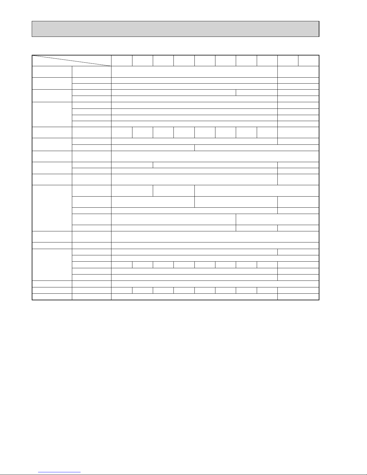
Specifi cations and rating conditions of main electric parts
Model
Item
MUZ-
GE25VA
MUZ-
GE25VAH
MUZ-
GE35VA
MUZ-
GE35VAH
MUZ-
GE42VA
MUZ-
GE42VAH
MUZ-
GE50VA
MUZ-
GE50VAH
MUZ-
GE60VA
MUZ-
GE71VA
Current
transformer
(CT) 20 A —
Smoothing
capacitor
(C61, C62, C63) 620 μF 420 V —
(CB1, CB2, CB3)
— 560 μF 450 V
Diode module
(DB61) 15 A 600 V 25 A 600 V —
(DB65) 25 A 600 V —
Fuse
(F62) — T2.0AL250 V
(F61) T20AL250V —
(F701, F801, F901)
T3.15AL250V —
(F601, F880, F901)
— T3.15AL250 V
Defrost heater (H) —
230 V
130 W
—
230 V
130 W
—
230 V
130 W
—
230 V
120 W
—
Intelligent power
module
(IC932) — 5 A 600 V
(IPM) 15 A 600 V 20 A 600 V
Expansion valve
coil
(LEV) 12 V DC
Reactor
(L61) 18 mH 23 mH —
(L) — 340 μH
Power factor
controller
(PFC) — 20 A 600 V
Currentdetecting
resistor
(R61)
45 mΩ 5 W
(1 element)
100 mΩ 5 W
(2 elements)
—
(R61,R62) —
180 mΩ 5 W
(2 elements)
—
(R825) 25 mΩ 5 W —
(R937, R938,
R939)
430 mΩ 2 W —
(R937A,R937B) — 1.1 Ω 2 W —
Current-limiting
PTC thermistor
(PTC64,
PTC65)
33 Ω
Terminal block (TB1, TB2) 3 P
Relay
(X63) 3 A 250 V —
(X64) 20 A 250 V
(X66) —
3 A 250 V
—
3 A 250 V
—
3 A 250 V
—
3 A 250 V
—
(X601) — 3 A 250 V
(X602) — 3 A 250 V
R.V.coil (21S4) 220 - 240 V AC
Heater protector (26H) —
Open 45°C
—
Open 45°C
—
Open 45°C
—
Open 45°C
—
IGBT (TR821) 30 A 600 V —
7
90
80
70
60
50
40
30
20
10
63 125 250 500 1000 2000 4000 8000
NC-60
NC-50
NC-40
NC-30
NC-20
NC-70
OCTAVE BAND SOUND PRESSURE LEVEL, 0dB re 0.0002 MICRO BAR
BAND CENTER FREQUENCIES, Hz
COOLING
FUNCTION
SPL(dB(A)) LINE
HEATING
47
48
NC-10
MUZ-GE25VA MUZ-GE25VAH
90
80
70
60
50
40
30
20
10
63 125 250 500 1000 2000 4000 8000
NC-60
NC-50
NC-40
NC-30
NC-20
NC-70
OCTAVE BAND SOUND PRESSURE LEVEL, dB re 0.0002 MICRO BAR
BAND CENTER FREQUENCIES, Hz
COOLING
FUNCTION
SPL(dB(A))
LINE
HEATING
47
48
NC-10
MUZ-GE35VA MUZ-GE35VAH
90
80
70
60
50
40
30
20
10
63 125 250 500 1000 2000 4000 8000
NC-60
NC-50
NC-40
NC-30
NC-20
NC-70
OCTAVE BAND SOUND PRESSURE LEVEL, 0dB re 0.0002 MICRO BAR
BAND CENTER FREQUENCIES, Hz
COOLING
FUNCTION
SPL(dB(A)) LINE
HEATING
50
NC-10
51
MUZ-GE42VA MUZ-GE42VAH
90
80
70
60
50
40
30
20
10
63 125 250 500 1000 2000 4000 8000
NC-60
NC-50
NC-40
NC-30
NC-20
NC-70
OCTAVE BAND SOUND PRESSURE LEVEL, dB re 0.0002 MICRO BAR
BAND CENTER FREQUENCIES, Hz
COOLING
FUNCTION
SPL(dB(A)) LINE
HEATING
54
NC-10
56
MUZ-GE50VA MUZ-GE50VAH
NOISE CRITERIA CURVES
4
8
MUZ-GE60VA MUZ-GE71VA
Test conditions
Cooling: Dry-bulb temperature 35°C
Heating: Dry-bulb temperature 7°C Wet-bulb temperature 6°C
OUTDOOR UNIT
MICROPHONE
1 m
90
80
70
60
50
40
30
20
10
63 125 250 500 1000 2000 4000 8000
NC-60
NC-50
NC-40
NC-30
NC-20
NC-70
OCTAVE BAND SOUND PRESSURE LEVEL, 0dB re 0.0002 MICRO BAR
BAND CENTER FREQUENCIES, Hz
COOLING
FUNCTION
SPL(dB(A)) LINE
HEATING
55
NC-10
55
90
80
70
60
50
40
30
20
10
63 125 250 500 1000 2000 4000 8000
NC-60
NC-50
NC-40
NC-30
NC-20
NC-70
OCTAVE BAND SOUND PRESSURE LEVEL, 0dB re 0.0002 MICRO BAR
BAND CENTER FREQUENCIES, Hz
COOLING
FUNCTION
SPL(dB(A)) LINE
HEATING
55
NC-10
55
9
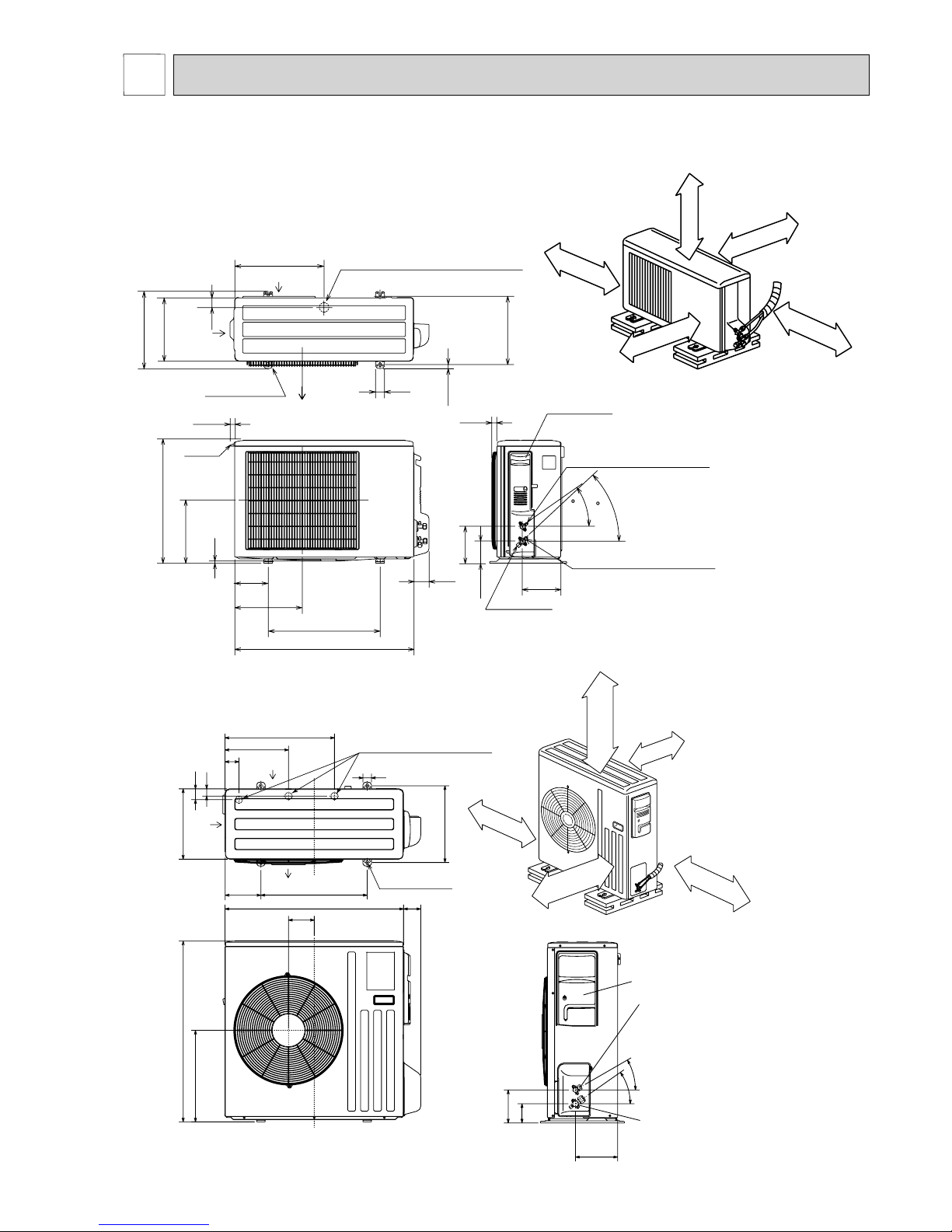
Unit: mm
MUZ-GE25VA MUZ-GE25VAH MUZ-GE35VA MUZ-GE35VAH
MUZ-GE42VA MUZ-GE42VAH
10
69
800
302.5
500 Bolt pitch for installation
150
22.3
Handle
550
280
164.5
99.5
170.5
23
Service panel
Service port
285
344.5
44
400
Air in
Air out
Air in
17.5
Bolt pitch for
installation
304~325
40
Liquid refrigerant pipe joint
Refrigerant pipe (flared) ø6.35
Gas refrigerant pipe joint
Refrigerant pipe (flared) ø9.52
43
35
2 holes 10 X 21
REQUIRED SPACE
100 mm or more
350 m
m o
r more
200 mm or more
100 mm or more
100 mm or more
Drain hole ø42 (MUZ-GE25/35/42VA)
Drain hole ø33 (MUZ-GE25/35/42VAH)
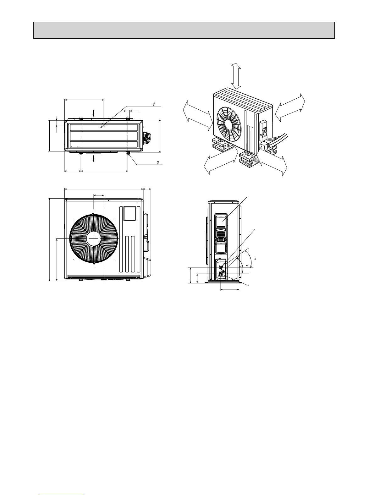
MUZ-GE50VA MUZ-GE50VAH
OUTLINES AND DIMENSIONS
5
30°
35°
155
90
198
40
515
299
66
34
51
330
360
850
430
500
80
121
840
Service panel
Gas refrigerant
pipe joint
Refrigerant pipe
(flared) ø12.7
Liquid refrigerant
pipe joint
Refrigerant pipe
(flared) ø6.35
170
500 mm or more
100 mm or more
500 mm or more
350 mm or more
100 mm o
r mo
re
REQUIRED SPACE
Air in
Air out
Air in
4 holes 10 × 21
Drain holes ø33(MUZ-GE50VA)
10
MUZ-GE60VA MUZ-GE71VA
417.5
40
42
Drain hole
175
500
330
50
Air in
Air out
2-holes 10 21
360
840
109
81
880
452
Service panel
99.5
164.5
195
35
44
Liquid refrigerant
pipe joint
Refrigerant pipe
(flared) Ø 6.35 (MUZ-GE60VA)
Ø 9.52 (MUZ-GE71VA)
Gas refrigerant
pipe joint
Refrigerant pipe
(flared)
Ø 15.88
350 mm or more
100 mm or more
REQUIRED SPACE
500 mm or more
100 mm or more
500 mm or more
Unit: mm
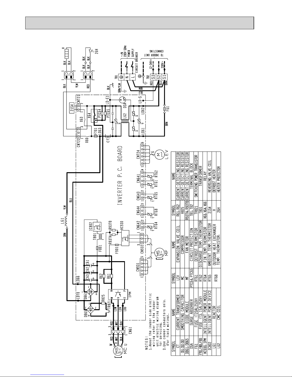
11
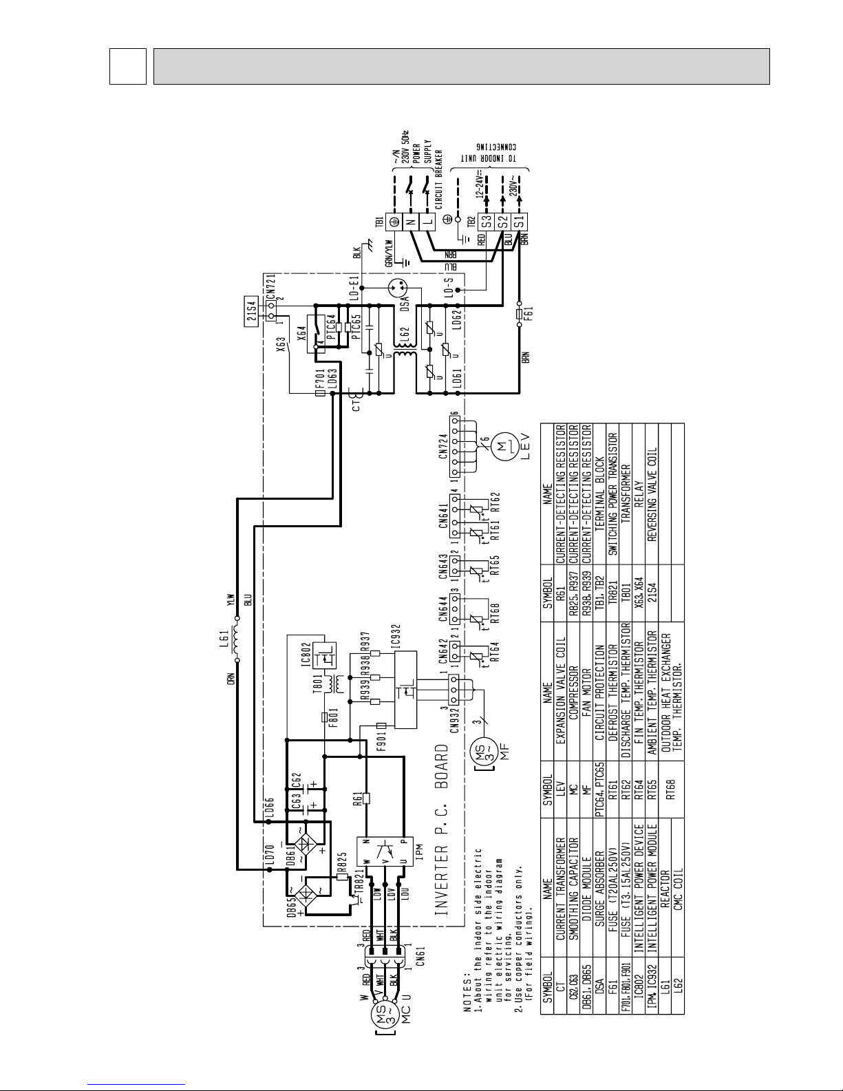
MUZ-GE25VA MUZ-GE35VA
WIRING DIAGRAM
6
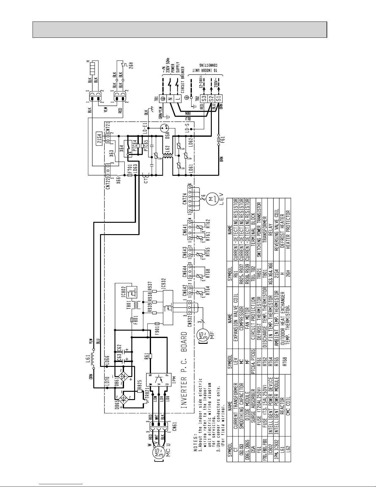
12
MUZ-GE25VAH MUZ-GE35VAH
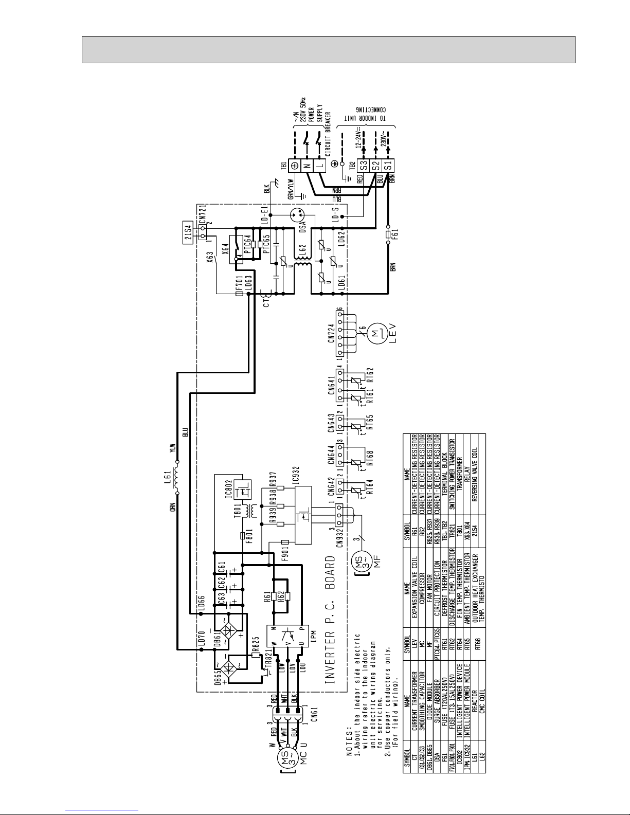
13
MUZ-GE42VA

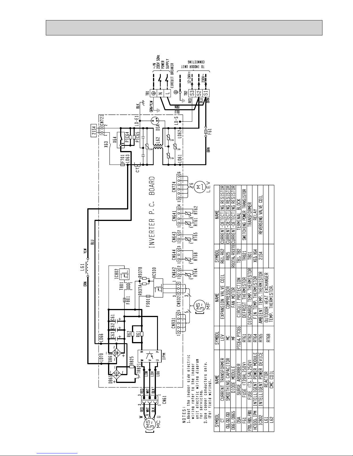
14
MUZ-GE42VAH
15
MUZ-GE50VA
16
MUZ-GE50VAH
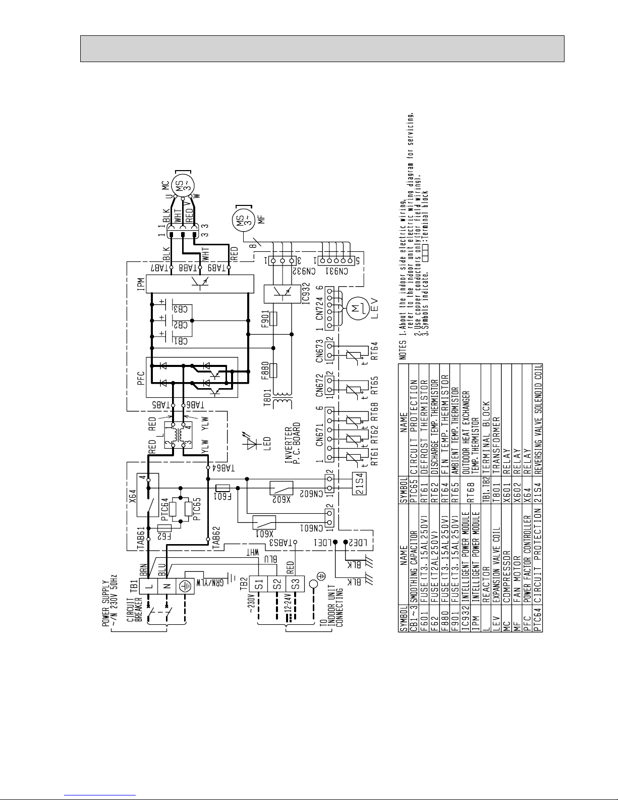
17
MUZ-GE60VA MUZ-GE71VA
18
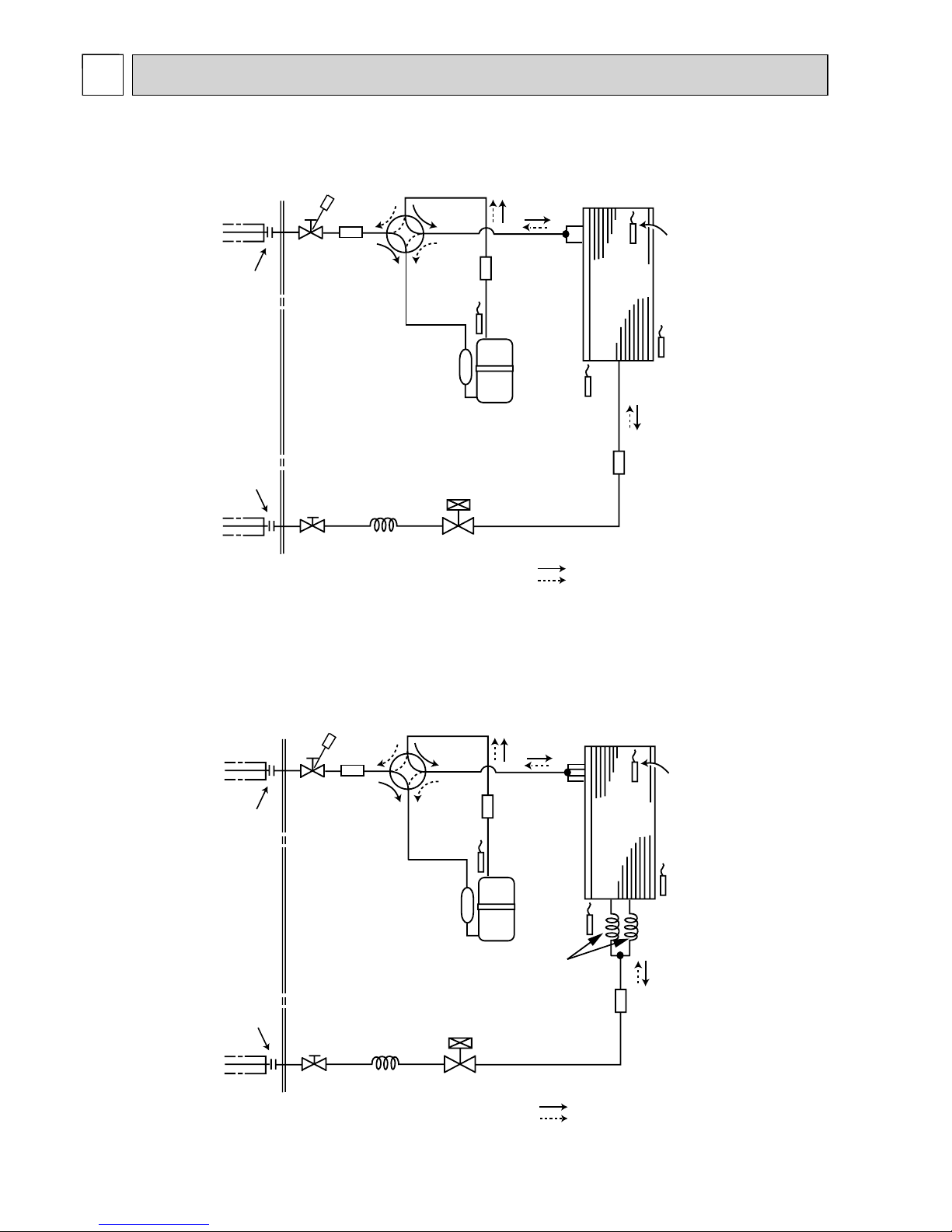
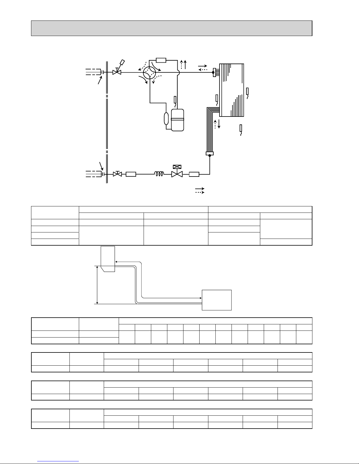
Unit: mm
MUZ-GE25VA MUZ-GE25VAH
Outdoor
heat
exchanger
Flared connection
Defrost
thermistor
RT61
Discharge
temperature
thermistor
RT62
Flared connection
Stop valve
(with strainar)
Stop valve
(with service port)
Refrigerant flow in cooling
Compressor
4-way valve
Refrigerant flow in heating
Refrigerant pipe ø9.52
(with heat insulator)
Refrigerant pipe ø6.35
(with heat insulator)
R.V. coil
heating ON
cooling OFF
Strainer
#100
LEV
Ambient
temperature
thermistor
RT65
Muffler
Capillary tube
ø3.0×ø2.0×240
Outdoor heat
exchanger
temperature
thermistor
RT68
Muffler
REFRIGERANT SYSTEM DIAGRAM
7
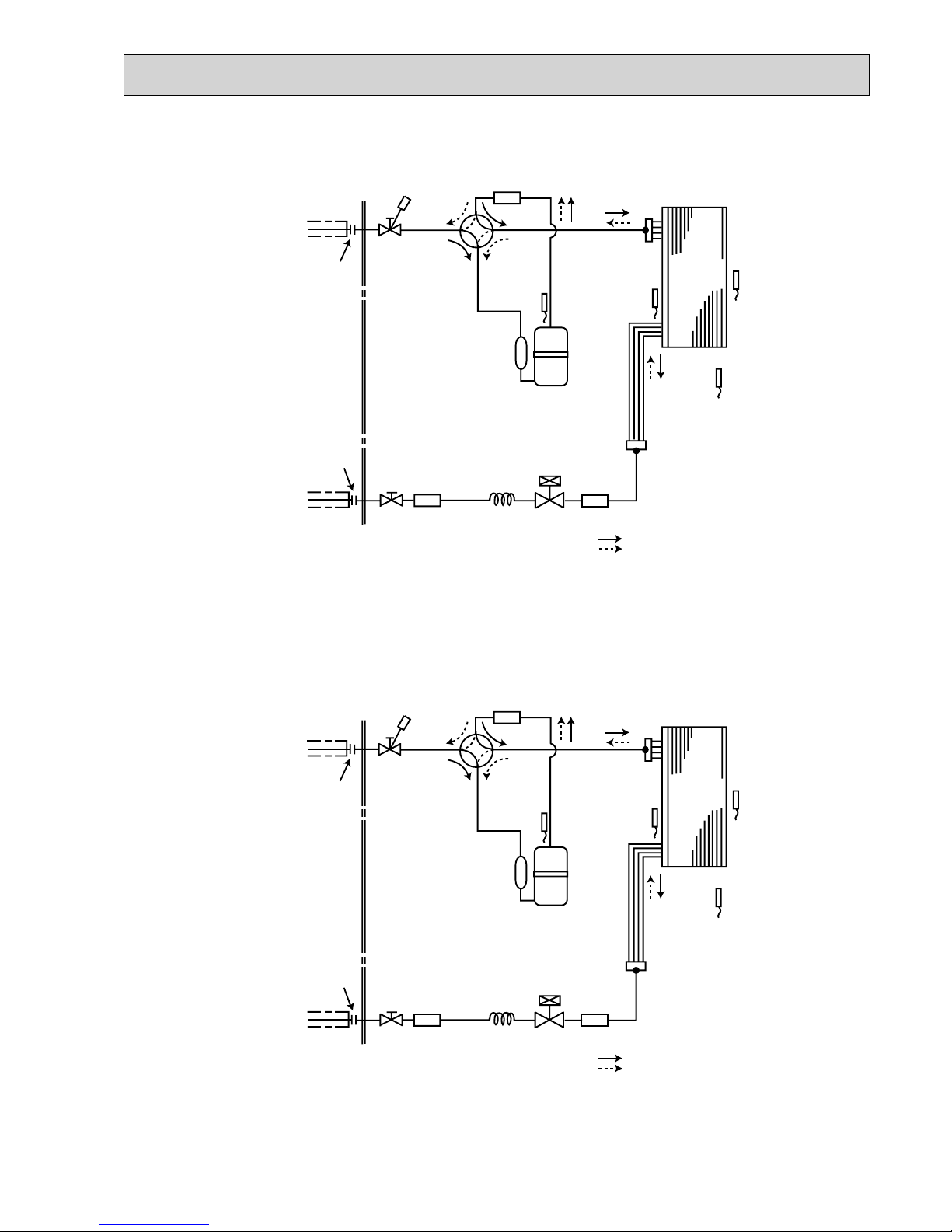
Unit: mm
MUZ-GE35VA MUZ-GE35VAH MUZ-GE42VA MUZ-GE42VAH
Outdoor
heat
exchanger
Flared connection
Defrost
thermistor
RT61
Discharge
temperature
thermistor
RT62
Flared connection
Stop valve
(with strainar)
Stop valve
(with service port)
Refrigerant flow in cooling
Compressor
4-way valve
Refrigerant flow in heating
Refrigerant pipe ø9.52
(with heat insulator)
Refrigerant pipe ø6.35
(with heat insulator)
R.V. coil
heating ON
cooling OFF
Strainer
#100
Capillary tube
ø3.0×ø1.8×600(×2)
LEV
Ambient
temperature
thermistor
RT65
Muffler
Capillary tube
ø3.0×ø2.0×240
Outdoor heat
exchanger
temperature
thermistor
RT68
Muffler
19
MUZ-GE50VA MUZ-GE50VAH
Outdoor
heat
exchanger
Flared connection
Defrost
thermistor
RT61
Discharge
temperature
thermistor
RT62
Flared connection
Stop valve
(with strainar)
Stop valve
(with service port)
Capillary tube
ø
3.6
×
ø
2.4×50
Refrigerant flow in cooling
Compressor
4-way valve
Refrigerant flow in heating
Refrigerant pipe
ø
12.7
(with heat insulator)
Refrigerant pipe ø6.35
(with heat insulator)
LEV
R.V. coil
heating ON
cooling OFF
Muffler
#100
Receiver
Outdoor heat
exchanger
temperature
thermistor
RT68
Ambient
temperature
thermistor
RT65
Strainer
#100
Unit: mm
MUZ-GE60VA
Outdoor
heat
exchanger
Flared connection
Defrost
thermistor
RT61
Discharge
temperature
thermistor
RT62
Flared connection
Stop valve
Stop valve
(with service port)
Capillary tube
ø
4.0
×
ø
2.4×100
Refrigerant flow in cooling
Compressor
4-way valve
Refrigerant flow in heating
Refrigerant pipe
ø
15.88
(with heat insulator)
Refrigerant pipe ø6.35
(with heat insulator)
LEV
R.V. coil
heating ON
cooling OFF
Muffler
#100
Strainer
#100
Outdoor heat
exchanger
temperature
thermistor
RT68
Ambient
temperature
thermistor
RT65
Strainer
#100
20
Max. Length
A
Max. Height
difference
B
Indoor
unit
Outdoor unit
MAX. REFRIGERANT PIPING LENGTH and MAX. HEIGHT DIFFERENCE
Refrigerant piping: m Piping size O.D: mm
Max. Length A Max. Height difference B Gas Liquid
MUZ-GE25/35/42 20 12 9.52
6.35MUZ-GE50
30 15
12.7
MUZ-GE60
15.88
MUZ-GE71 9.52
ADDITIONAL REFRIGERANT CHARGE (R410A: g)
Model
Outdoor unit
precharged
Refrigerant piping length (one way)
5 m 6 m 7 m 8 m 9 m 10 m 11 m 12 m 13 m 14 m 15 m 20 m
MUZ-GE25 800
0 0 0 30 60 90 120 150 180 210 240 390
MUZ-GE35/42 1,150
Calculation: X g = 30 g/m × (Refrigerant piping length (m) - 7)
Model
Outdoor unit
precharged
Refrigerant piping length (one way)
7 m 10 m 15 m 20 m 25 m 30 m
MUZ-GE50 1,550 0 60 160 260 360 460
Calculation: X g = 20 g/m × (Refrigerant piping length (m) – 7)
Model
Outdoor unit
precharged
Refrigerant piping length (one way)
7 m 10 m 15 m 20 m 25 m 30 m
MUZ-GE60 1,550 0 0 100 200 300 400
Calculation: X g = 20 g/m × (Refrigerant piping length (m) – 10)
Model
Outdoor unit
precharged
Refrigerant piping length (one way)
7 m 10 m 15 m 20 m 25 m 30 m
MUZ-GE71 1,900 0 0 275 550 825 1,100
Calculation: X g = 55 g/m × (Refrigerant piping length (m) – 10)
NOTE: Refrigerant piping exceeding 7 m requires additional refrigerant charge according to the calculation.
MUZ-GE71VA
Outdoor
heat
exchanger
Flared connection
Defrost
thermistor
RT61
Discharge
temperature
thermistor
RT62
Flared connection
Stop valve
Stop valve
(with service port)
Capillary tube
ø
4.0
×
ø
2.4×100
Refrigerant flow in cooling
Compressor
4-way valve
Refrigerant flow in heating
Refrigerant pipe
ø
15.88
(with heat insulator)
Refrigerant pipe ø9.52
(with heat insulator)
LEV
R.V. coil
heating ON
cooling OFF
Muffler
#100
Strainer
#100
Outdoor heat
exchanger
temperature
thermistor
RT68
Ambient
temperature
thermistor
RT65
Strainer
#100
Unit: mm
21
The standard specifications apply only to the operation of the air conditioner under normal conditions. Since operating condi-
tions vary according to the areas where these units are installed, the following information has been provided to clarify the
operating characteristics of the air conditioner under the conditions indicated by the performance curve.
(1) GUARANTEED VOLTAGE
198 ~ 264 V, 50 Hz
(2) AIR FLOW
Air flow should be set at MAX.
(3) MAIN READINGS
(1) Indoor intake air wet-bulb temperature: °C [WB]
}
Cooling
(2) Indoor outlet air wet-bulb temperature: °C [WB]
(3) Outdoor intake air dry-bulb temperature: °C [DB]
(4) Total input: W
(5) Indoor intake air dry-bulb temperature: °C [DB]
}
Heating(6) Outdoor intake air wet-bulb temperature: °C [WB]
(7) Total input: W
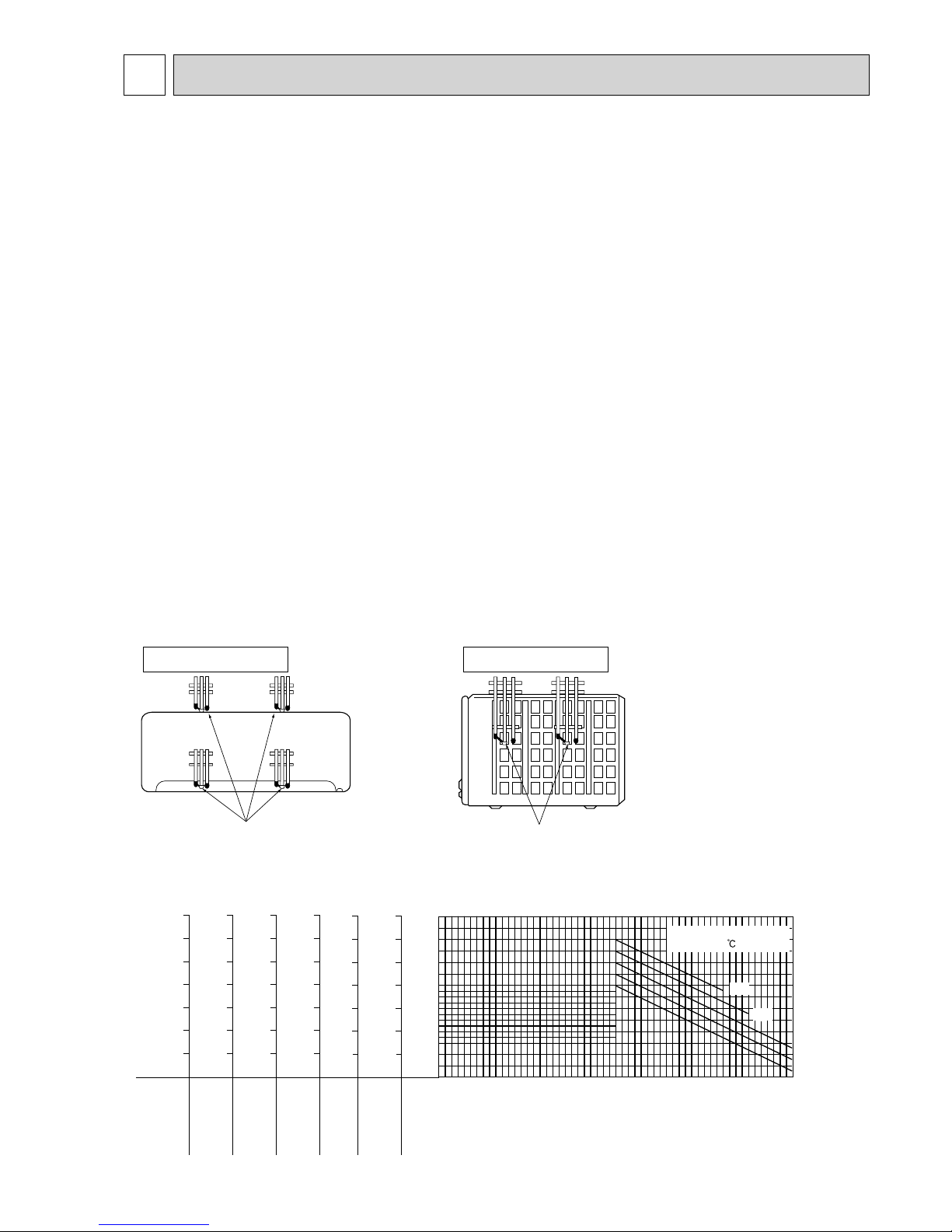
Indoor air wet/dry bulb temperature difference on the left side of the following chart shows the difference between the
indoor intake air wet/dry bulb temperature and the indoor outlet air wet/dry bulb temperature for your reference at service.
How to measure the indoor air wet bulb / dry bulb temperature difference
1. Attach at least 2 sets of wet and dry bulb thermometers to the indoor air intake as shown in the figure, and at least 2 sets
of wet and dry bulb thermometers to the indoor air outlet. The thermometers must be attached to the position where air
speed is high.
2. Attach at least 2 sets of wet and dry bulb thermometers to the outdoor air intake.
Cover the thermometers to prevent direct rays of the sun.
3. Check that the air filter is cleaned.
4. Open windows and doors of room.
5. Press the EMERGENCY OPERATION switch once (twice) to start the EMERGENCY COOL (HEAT) MODE.
6. When system stabilizes after more than 15 minutes, measure temperature and take an average temperature.
7. 10 minutes later, measure temperature again and check that the temperature does not change.
MUZ-GE25VA MUZ-GE25VAH MUZ-GE35VA MUZ-GE35VAH MUZ-GE42VA MUZ-GE42VAH
MUZ-GE50VA MUZ-GE50VAH MUZ-GE60VA MUZ-GE71VA
INDOOR UNIT OUTDOOR UNIT
Wet and dry bulb
thermometers
FRONT VIEW
Wet and dry bulb
thermometers
BACK VIEW
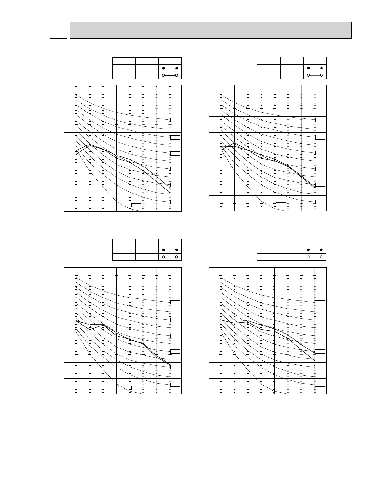
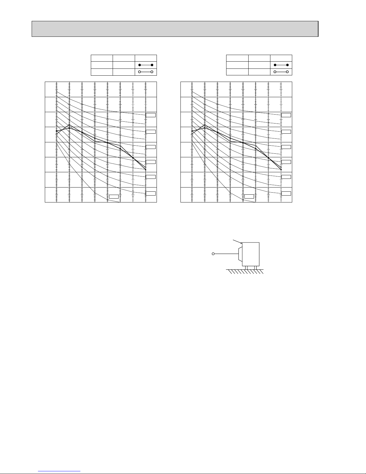
Cooling capacity (
at Rated frequency)
0.9
1.0
1.1
1.2
1.3
1.4
1.5
-10-5 0 5 1015202530354045
Outdoor intake air Dry-bulb temperature(°C)
Capacity correction factors
26
24
20
18
22
Indoor intake air Wet-bulb
temperature( )
10.4
9.5
8.7
8.0
7.2
6.5
5.7
MUZ-GE50VA
MUZ-GE50VAH
MUZ-GE42VA
MUZ-GE42VAH
MUZ-GE35VA
MUZ-GE35VAH
MUZ-GE25VA
MUZ-GE25VAH
Indoor air Wet-bulb temperature
difference (°C)
6.6
6.1
5.6
5.1
4.6
4.2
3.7
8.4
7.7
7.1
6.5
5.9
5.3
4.7
10.2
9.4
8.6
7.9
7.1
6.4
5.7
9.3
8.6
7.9
7.2
6.5
5.8
5.2
9.7
8.9
8.2
7.5
6.8
6.1
5.4
MUZ-GE71VA
MUZ-GE60VA
8-1. CAPACITY AND INPUT CURVES
PERFORMANCE CURVES8
 Loading...