

Mitsubishi Electronics MUZ-GE80VAD, MUZ-GE80VA, MUZ-GE80VA2, MUZ-GE71VAD, MUZ-GE60VAD User Manual
...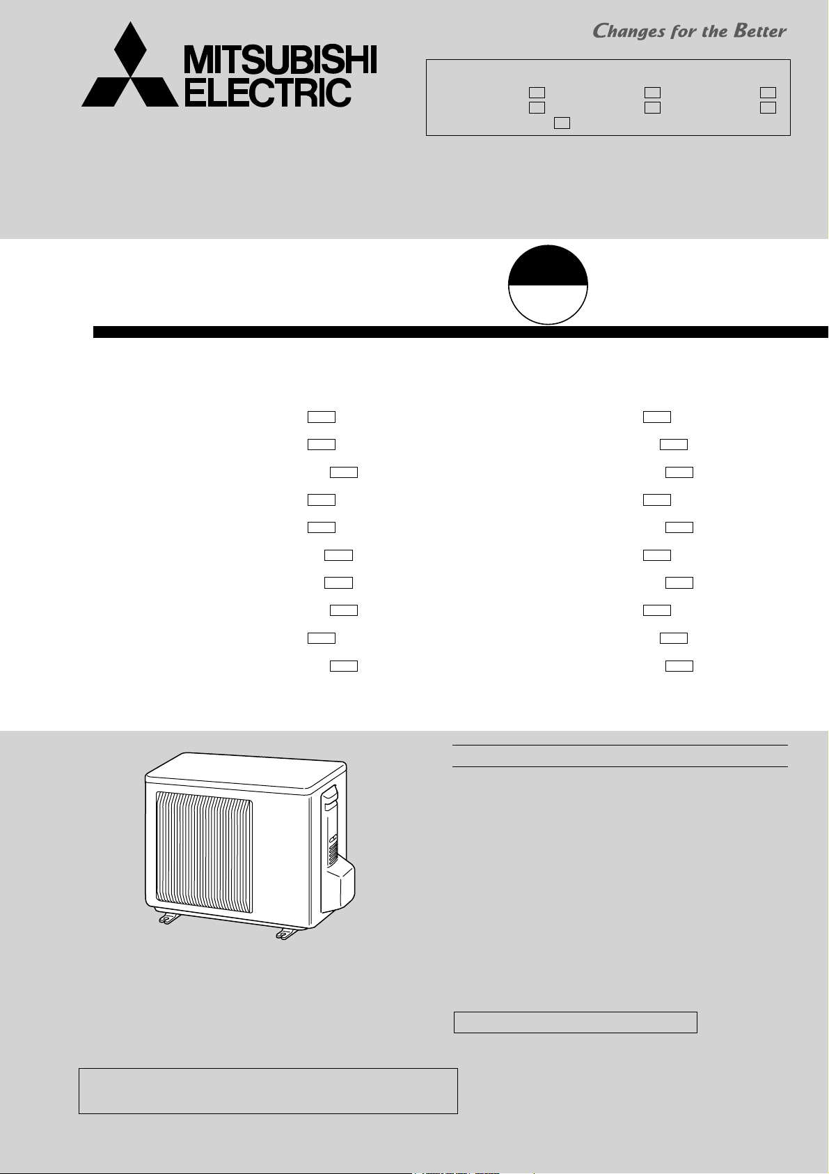
SPLIT-TYPE AIR CONDITIONERS
OUTDOOR UNIT
Revision E:
• MUZ-GE25VAD-A1, MUZ-GE35VAD-A1, MUZ-GE42VAD-A1,
MUZ-GE50VAD-A1, MUZ-GE60VAD-A1, MUZ-GE71VAD-A1
and MUZ-GE80VAD-A1 have been added.
Please void OBH532 REVISED EDITION-D.
SERVICE MANUAL
Models
A1
MUZ-GE25VA
MUZ-GE25VA
MUZ-GE25VAD
MUZ-GE33VA
MUZ-GE35VA
MUZ-GE35VA2
MUZ-GE35VA2
MUZ-GE35VAD
MUZ-GE42VA
-
A2
-
A1
-
A1
-
A1
-
A1
-
A2
-
A1
-
A1
-
MUZ-GE50VA
MUZ-GE50VA2
MUZ-GE50VAD
MUZ-GE60VA
MUZ-GE60VAD
MUZ-GE71VA
MUZ-GE71VAD
MUZ-GE80VA
MUZ-GE80VA2
HFC
utilized
R410A
No. OBH532
REVISED EDITION-E
A1
-
A1
-
A1
-
A1
-
A1
-
A1
-
A1
-
A1
-
A1
-
MUZ-GE42VAD
MUZ-GE25VA
MUZ-GE25VAD
MUZ-GE33VA
MUZ-GE35VA
MUZ-GE35VA2
MUZ-GE35VAD
MUZ-GE42VA
MUZ-GE42VAD
A1
-
MUZ-GE80VAD
Indoor unit service manual
MSZ-GE•VA Series (OBH531)
CONTENTS
1. TECHNICAL CHANGES ··································· 3
2. PART NAMES AND FUNCTIONS ····················· 4
3. SPECIFICATION ················································ 6
4. NOISE CRITERIA CURVES ·····························11
5. OUTLINES AND DIMENSIONS ······················ 13
6. WIRING DIAGRAM ·········································· 15
7. REFRIGERANT SYSTEM DIAGRAM ············· 27
8. PERFORMANCE CURVES ····························· 31
9. ACTUATOR CONTROL ··································· 63
10. SERVICE FUNCTIONS ···································· 64
11. TROUBLESHOOTING ····································· 65
12. DISASSEMBLY INSTRUCTIONS ···················· 86
PARTS CATALOG (OBB532)
A1
-
NOTE:
RoHS compliant products have <G> mark on the spec name plate.
Use the specified refrigerant only
OBH532E
Never use any refrigerant other than that specified.
Doing so may cause a burst, an explosion, or fire when the unit is being used, serviced, or disposed of.
Correct refrigerant is specified in the manuals and on the spec labels provided with our products.
We will not be held responsible for mechanical failure, system malfunction, unit breakdown or accidents caused by
failure to follow the instructions.
Revision A :
• MUZ-GE60VA-A1, MUZ-GE71VA-A1 and MUZ-GE80VA-A1 have been added.
Revision B:
• MUZ-GE33VA-A1 and MUZ-GE42VA-A1 have been added.
Revision C:
• MUZ-GE35VA2-A1, MUZ-GE50VA2-A1 and MUZ-GE80VA2-A1 have been added.
Revision D:
• MUZ-GE25VA-A2 and MUZ-GE35VA2-A2 have been added.
Revision E:
• MUZ-GE25VAD-A1, MUZ-GE35VAD-A1, MUZ-GE42VAD-A1, MUZ-GE50VAD-A1, MUZ-GE60VAD-A1, MUZ-GE71VAD-A1
and MUZ-GE80VAD-A1 have been added.
2
1
OBH532E
TECHNICAL CHANGES
MUZ-GE25VA MUZ-GE33VA MUZ-GE35VA MUZ-GE42VA MUZ-GE50VA MUZ-GE60VA MUZ-GE71VA MUZ-GE80VA -
1. New model
MUZ-GE35VA MUZ-GE50VA MUZ-GE80VA -
1. Inverter P.C. board has been changed.
MUZ-GE25VA -
1. Compressor has been changed.
2. Back panel has been changed.
3. Outdoor heat exchanger has been changed.
4. Reactor has been changed.
5. Inverter P.C. board has been changed.
6. Maximum heating capacity has been changed.
A1
A1
A1
A1
A1
A1
A1
A1
A1
A1
A1
A1
MUZ-GE35VA2 MUZ-GE50VA2 MUZ-GE80VA2 -
MUZ-GE25VA -
A1
A1
A1
A2
A2
A1
A1
A1
A1
A2
A1
A1
MUZ-GE35VA2 -
MUZ-GE25VAD -
MUZ-GE35VAD -
MUZ-GE42VAD -
MUZ-GE50VAD -
MUZ-GE60VAD MUZ-GE71VAD -
MUZ-GE80VAD -
MUZ-GE35VA2 -
1. Compressor has been changed.
2. Back panel has been changed.
3. Outdoor heat exchanger has been changed.
4. Inverter P.C. board has been changed.
MUZ-GE25VA MUZ-GE35VA2 MUZ-GE42VA MUZ-GE50VA2 -
1. Inverter P.C. board has been changed.
MUZ-GE60VA MUZ-GE71VA MUZ-GE80VA2 -
1. Outdoor heat exchanger has been changed.
2. R.V coil has been changed.
3. 4-Way valve has been changed.
4. Service panel has been changed.
5. Terminal block has been changed.
6. Inverter P.C. board has been changed.
A2
A1
A1
A1
A1
A1
A1
A1
3
2
OBH532E
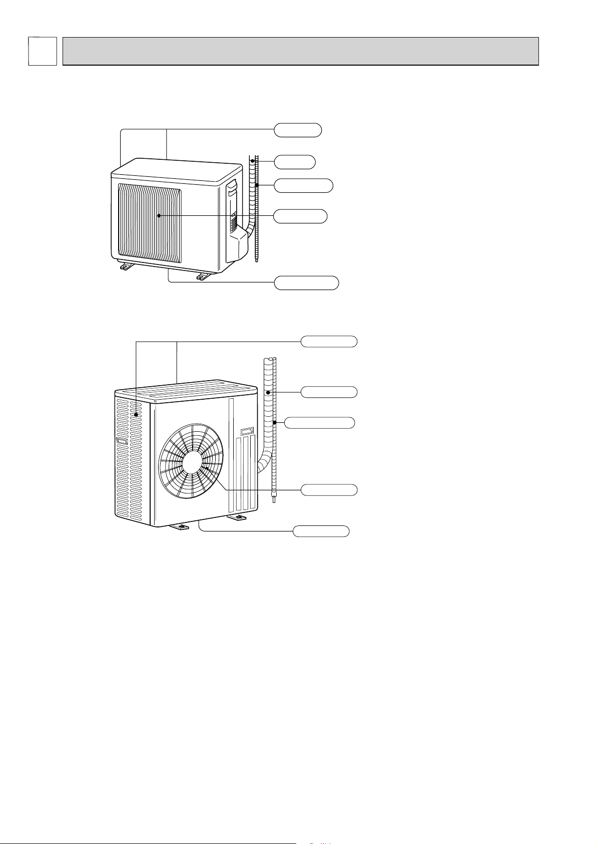
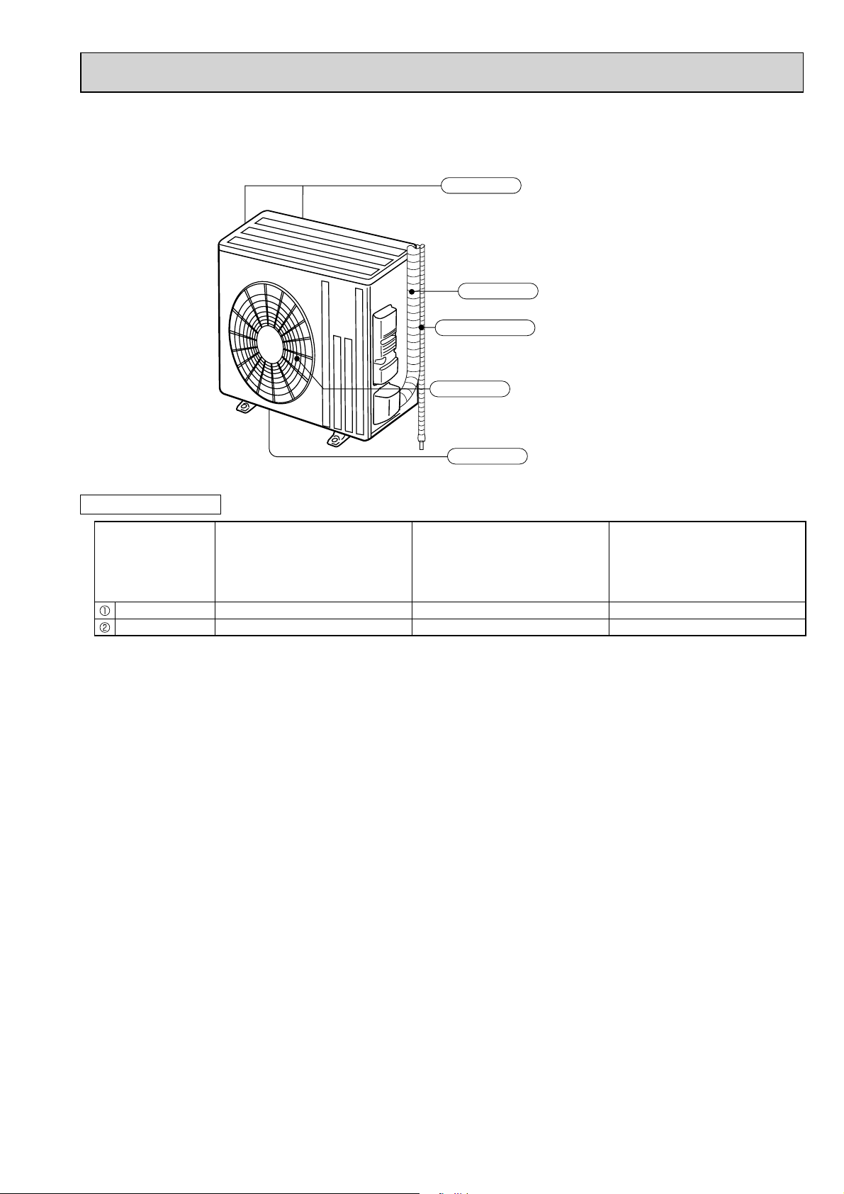
PART NAMES AND FUNCTIONS
MUZ-GE25VA MUZ-GE25VAD MUZ-GE33VA
MUZ-GE35VA MUZ-GE35VA2 MUZ-GE35VAD MUZ-GE42VA MUZ-GE42VAD
Air inlet
(back and side)
Piping
Drain hose
Air outlet
Drain outlet
MUZ-GE50VA MUZ-GE50VA2 MUZ-GE50VAD
Air inlet
(back and side)
Piping
Drain hose
Air outlet
Drain outlet
4
MUZ-GE60VA MUZ-GE60VAD MUZ-GE71VA MUZ-GE71VAD
OBH532E
MUZ-GE80VA MUZ-GE80VA2 MUZ-GE80VAD
Air inlet
(back and side)
Piping
Drain hose
Air outlet
Drain outlet
ACCESSORIES
MUZ-GE25VA MUZ-GE25VAD
MUZ-GE33VA
Model
Drain socket 1 1 1
Drain cap - 2 -
MUZ-GE35VA MUZ-GE35VA2
MUZ-GE35VAD
MUZ-GE42VA MUZ-GE42VAD
MUZ-GE50VA
MUZ-GE50VA2
MUZ-GE50VAD
MUZ-GE60VA MUZ-GE60VAD
MUZ-GE71VA MUZ-GE71VAD
MUZ-GE80VA MUZ-GE80VA2
MUZ-GE80VAD
5
3
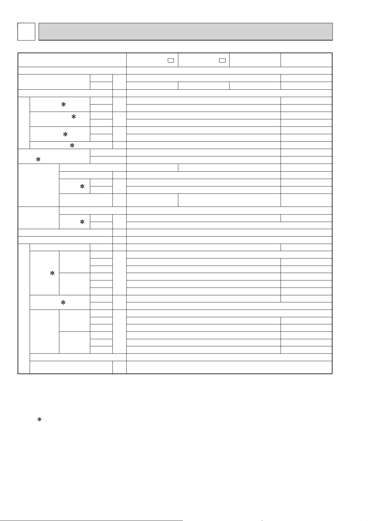
OBH532E
SPECIFICATION
Outdoor model MUZ-GE25VA-
Power supply
Capacity
Rated frequency (Min.-Max.)
Breaker Capacity
Power input 1 (Total)
Running current 1
(Total)
Power factor 1 (Total)
Electrical data
Starting current 1 (Total)
Coeffi cient of performance
(COP) 1 (Total)
Model
Output
Compressor
Current 1
Refrigeration oil
(Model)
Model
Fan motor
Current 1
Dimensions W × H × D
Weight
Dehumidifi cation Cooling
Cooling
Air fl ow 1
Heating
Sound level 1
Cooling
Special remarks
Fan speed
Heating
Fan speed regulator
Refrigerant fi lling capacity
(R410A)
Cooling
Heating
Cooling
Heating
Cooling
Heating
Cooling
Heating
Cooling
Heating
Cooling
Heating
Cooling
Heating
High
Med.
Low
High
Med.
Low
Cooling
Heating
High
Med.
Low
High
Med.
Low
A1
MUZ-GE25VA-
Single phase, 230 V, 50 Hz
kW
A10
W
A
%
A 3.8 4.8
W 550 650
A
L 0.32 (NEO22) 0.36 (NEO22) 0.32 (NEO22)
A
mm 800 × 550 × 285
kg 30
L/h 0.2 0.6
m3/h
dB(A)
rpm
kg 0.80
3.2 (1.3 - 4.5) 3.2 (1.3 - 4.1) 3.2 (1.3 - 4.5) 4.0 (1.4 - 4.8)
KNB073FFDHC KNB073FKVHC KNB092FFAHC
2.5 (1.1 - 3.5) 3.3(1.4 - 3.9)
560 910
730 1,030
2.9 4.3
3.8 4.8
84 92
84 93
4.46 3.63
4.38 3.88
2.44 3.70
3.30 4.30
0.24 0.31
1,806 1,956
1,170 1,806
2,106 2,130
1,806 1,956
1,452 1,476
46 47
740 800
490 740
860 870
740 800
600 610
A2
MUZ-GE25VAD MUZ-GE33VA
RC0J50-DB
0.27
–
48
–
3
NOTE: Test conditions are based on AS/NZS 3823.1.1.
Cooling: Indoor Dry-bulb temperature 27°C Wet-bulb temperature 19°C
Outdoor Dry-bulb temperature 35°C Wet-bulb temperature (24°C)
Heating: Indoor Dry-bulb temperature 20°C Wet-bulb temperature 15.5°C
Outdoor Dry-bulb temperature 7°C Wet-bulb temperature 6°C
Refrigerant piping length (one way): 5 m
1 Measured under rated operating frequency.
6
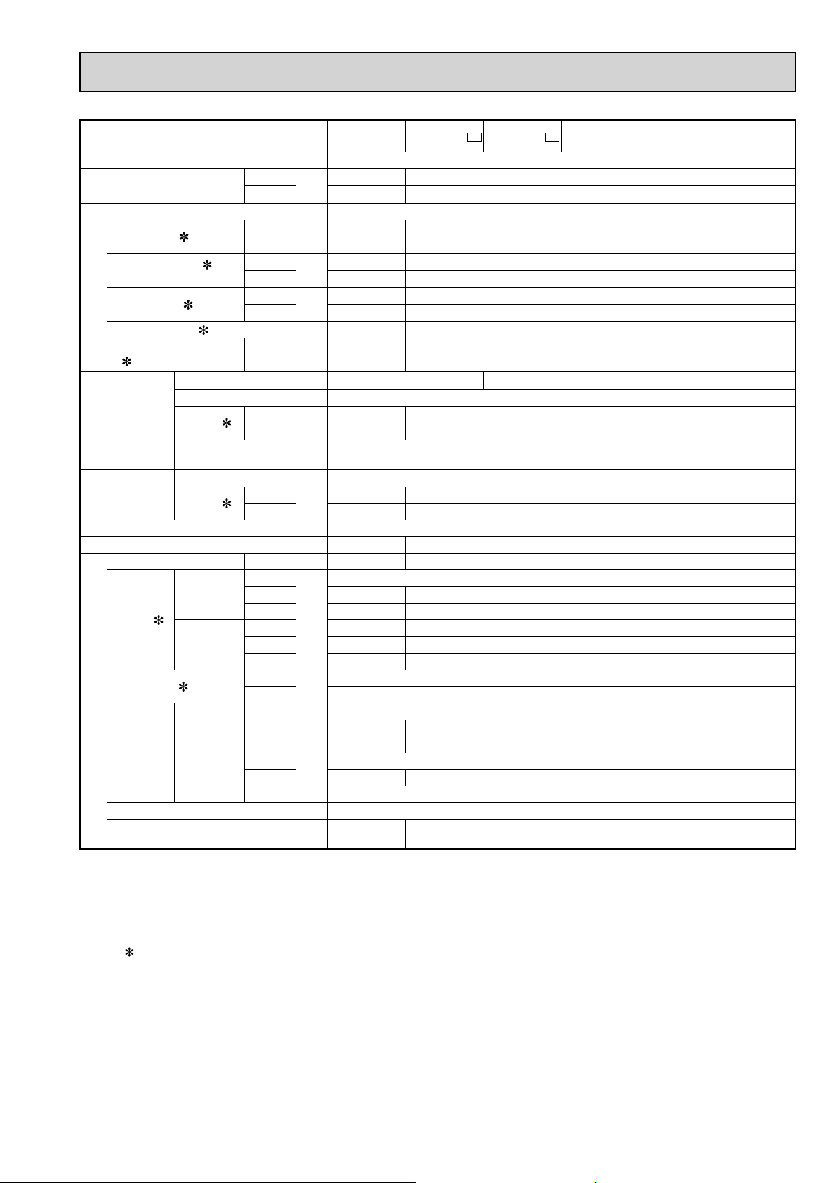
Outdoor model
OBH532E
MUZ-GE35VA MUZ-GE35VA2-A1MUZ-GE35VA2-A2MUZ-GE35VAD MUZ-GE42VA MUZ-GE42VAD
Power supply
Capacity
Rated frequency (Min.-Max.)
Breaker Capacity
Power input 1 (Total)
Running current 1
(Total)
Power factor 1 (Total)
Electrical data
Starting current 1 (Total)
Coeffi cient of performance
(COP) 1 (Total)
Model
Output
Compressor
Current 1
Refrigeration oil
(Model)
Model
Fan motor
Current 1
Dimensions W × H × D
Weight
Dehumidifi cation Cooling
Cooling
Air fl ow 1
Heating
Sound level 1
Cooling
Special remarks
Fan speed
Heating
Fan speed regulator
Refrigerant fi lling capacity
(R410A)
Cooling
Heating
Cooling
Heating
Cooling
Heating
Cooling
Heating
Cooling
Heating
Cooling
Heating
Cooling
Heating
High
Med.
Low
High
Med.
Low
Cooling
Heating
High
Med.
Low
High
Med.
Low
3.5 (1.4 - 3.9) 3.5 (1.1 - 4.0) 4.2(0.9-4.8)
kW
4.0 (1.4 - 4.8) 4.0 (1.6 - 5.3) 5.4(1.4-6.0)
A10
W
A
%
A 4.8 4.6 7.0
W 650 900
A
L 0.32 (NEO22) 0.45 (NEO22)
A
mm 800 × 550 × 285
kg 30 33 36
L/h 0.8 0.9 1.4
m3/h
dB(A)
rpm
kg 0.80 1.15
1,010 920 1,260
1,030 990 1,540
4.7 4.4 5.8
4.8 4.6 7.0
93 91 94
93 94 96
3.47 3.80 3.33
3.88 4.04 3.51
KNB092FFAHC KNB092FNDHC SNB130FGBHT
4.10 3.76 5.19
4.30 4.06 6.38
0.31 0.35 0.32
0.27 0.31
1,956 1,872
1,806 1,776 1,086
2,130 2,016
1,956 1,776
1,476 1,386
800 810
740 770 490
800 770
Single phase, 230 V, 50 Hz
RC0J50-DB RC0J50-EA
–
47 50
48 51
–
870
610
3
NOTE: Test conditions are based on AS/NZS 3823.1.1.
Cooling: Indoor Dry-bulb temperature 27°C Wet-bulb temperature 19°C
Outdoor Dry-bulb temperature 35°C Wet-bulb temperature (24°C)
Heating: Indoor Dry-bulb temperature 20°C Wet-bulb temperature 15.5°C
Outdoor Dry-bulb temperature 7°C Wet-bulb temperature 6°C
Refrigerant piping length (one way): 5 m
1 Measured under rated operating frequency.
7
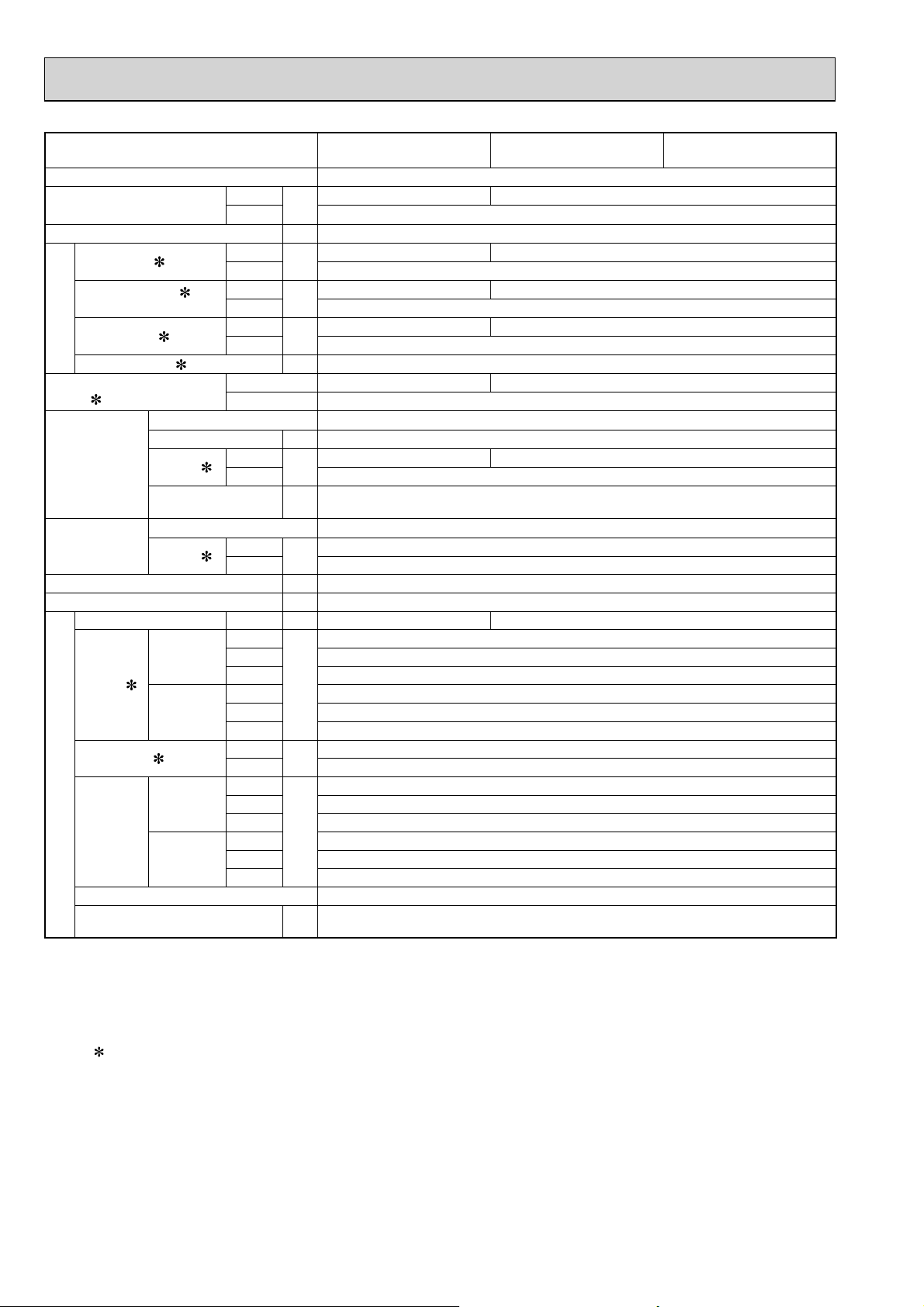
Outdoor model MUZ-GE50VA MUZ-GE50VA2 MUZ-GE50VAD
OBH532E
Power supply
Capacity
Rated frequency (Min.-Max.)
Breaker Capacity
Power input 1 (Total)
Running current 1
(Total)
Power factor 1 (Total)
Electrical data
Starting current 1 (Total)
Coeffi cient of performance
(COP) 1 (Total)
Model
Output
Compressor
Current 1
Refrigeration oil
(Model)
Model
Fan motor
Current 1
Dimensions W × H × D
Weight
Dehumidifi cation Cooling
Cooling
Air fl ow 1
Heating
Sound level 1
Cooling
Special remarks
Fan speed
Heating
Fan speed regulator
Refrigerant fi lling capacity
(R410A)
Cooling
Heating
Cooling
Heating
Cooling
Heating
Cooling
Heating
Cooling
Heating
Cooling
Heating
Cooling
Heating
High
Med.
Low
High
Med.
Low
Cooling
Heating
High
Med.
Low
High
Med.
Low
kW
A16
W
A
%
A 7.4
W 900
A
L 0.45 (NEO22)
A
mm 840 × 850 × 330
kg 54
L/h 1.8 1.6
m3/h
dB(A)
rpm
kg 1.55
5.0 (1.4 - 5.4) 4.8 (1.4 - 5.4)
1,640 1,480
7.4 6.8
96 94
3.05 3.24
6.69 6.09
Single phase, 230 V, 50 Hz
5.8 (1.4 - 7.2)
1,650
7.4
96
3.52
SNB130FGBHT
6.72
RC0J60-AA
0.32
0.32
–
2,940
1,740
–
2,940
2,142
54
56
–
780
480
–
780
580
2
NOTE: Test conditions are based on AS/NZS 3823.1.1.
Cooling: Indoor Dry-bulb temperature 27°C Wet-bulb temperature 19°C
Outdoor Dry-bulb temperature 35°C Wet-bulb temperature (24°C)
Heating: Indoor Dry-bulb temperature 20°C Wet-bulb temperature 15.5°C
Outdoor Dry-bulb temperature 7°C Wet-bulb temperature 6°C
Refrigerant piping length (one way): 5 m
1 Measured under rated operating frequency.
8
Outdoor model
OBH532E
MUZ-GE60VA
MUZ-GE60VAD
MUZ-GE71VA
MUZ-GE71VAD
MUZ-GE80VA MUZ-GE80VA2
MUZ-GE80VAD
Power supply
Capacity
Rated frequency (Min.-Max.)
Breaker Capacity
Power input 1 (Total)
Running current 1
(Total)
Power factor 1 (Total)
Electrical data
Starting current 1 (Total)
Coeffi cient of performance
(COP) 1 (Total)
Model
Output
Compressor
Current 1
Refrigeration oil
(Model)
Model
Fan motor
Current 1
Dimensions W × H × D
Weight
Dehumidifi cation Cooling
Cooling
Air fl ow 1
Heating
Sound level 1
Cooling
Special remarks
Fan speed
Heating
Fan speed regulator
Refrigerant fi lling capacity
(R410A)
Cooling
Heating
Cooling
Heating
Cooling
Heating
Cooling
Heating
Cooling
Heating
Cooling
Heating
Cooling
Heating
High
Med.
Low
High
Med.
Low
Cooling
Heating
High
Med.
Low
High
Med.
Low
kW
A20
W
A
%
A 7.8 9.5 11.3 11.2
W 900 1,200
A
L 0.35 (FV50S) 0.4 (FV50S)
A
mm 840 × 880 × 330
kg 50 53
L/h 1.9 2.2 2.9 2.7
m3/h
dB(A)
rpm
kg 1.55 1.90
6.0 (1.5 - 7.5) 7.1 (2.4- 8.7)
6.8 (2.0 - 9.3) 8.1 (2.2 - 9.9) 9.0 (2.2 - 11.1)
1,760 2,130 2,560 2,460
1,770 2,110 2,540 2,550
7.8 9.4 11.3 10.8
7.8 9.5 11.2
98 99 98 99
98 97 99
3.40 3.41 3.33 3.12 3.17
3.84 3.83 3.84 3.54 3.53
SNB130FGBMT SNB172FEKMT
6.62 6.44 8.02 8.06 9.89 9.39 9.43
6.37 6.34 8.13 8.17 9.83 9.87
0.84 0.93 0.83 0.86
0.93 0.82
3,492 3,426
3,066 3,006
1,692 1,512
2,952 2,892
2,952 2,892
2,226 2,280
480 450
620 650
Single phase, 230 V, 50 Hz
RC0J60-BC
55
55
950
840
810
810
3
NOTE: Test conditions are based on AS/NZS 3823.1.1.
Cooling: Indoor Dry-bulb temperature 27°C Wet-bulb temperature 19°C
Outdoor Dry-bulb temperature 35°C Wet-bulb temperature (24°C)
Heating: Indoor Dry-bulb temperature 20°C Wet-bulb temperature 15.5°C
Outdoor Dry-bulb temperature 7°C Wet-bulb temperature 6°C
Refrigerant piping length (one way): 5 m
1 Measured under rated operating frequency.
8.0 (2.4 - 9.2)
7.8 (2.4 - 9.2)
9
Specifi cations and rated conditions of main electric parts
OBH532E
Item
Smoothing
capacitor
Diode module
Model
(C62, C63)
(DB61) 15 A 600 V 25 A 600 V
(DB65) 25 A 600 V
(
C61
MUZ-
GE25VA
)
MUZ-
GE25VAD
MUZ-
GE33VA
MUZ-
GE35VA
MUZ-
GE35VA2
MUZ-
GE35VAD
MUZ-
GE42VA
600 μF/620 μF 420 V —
— 600 μF/620 μF 420 V
MUZ-
GE42VAD
MUZ-
GE50VA
MUZ-
GE50VA2
MUZ-
GE50VAD
(F62) —
Fuse
Intelligent
(F701, F801, F901)
(F601,F880, F901)
(F61) T20AL250V
T3.15AL250V
—
(IC932) —
power module /
Power module
1.
Expansion valve
coil
Reactor
Power factor
controller
Current-limiting
PTC thermistor
(PTC64, PTC65) 33 Ω
(IPM) 15 A 600 V 20 A 600 V
(LEV) 12 VDC
(L61) 18 mH 23 mH
(L) —
(PFC) —
Terminal block (TB1, TB2) 3 P
(X63) 3 A 250 V
Relay
(X64) 20 A 250 V
(X601) —
(X602) —
R.V.coil (21S4) 220 - 240 VAC
IGBT (TR821) 30 A 600 V
1.
Intelligent power module: MUZ-GE25VA -
Power module: Other models
A1
, MUZ-GE35/50VA
Specifi cations and rated conditions of main electric parts
Item
Smoothing
capacitor
Diode module
Fuse
Intelligent power
module
(C61, C62, C63)
(
CB1, CB2, CB3
)
(DB61) —
(DB65) —
(F62)
(F61) —
(F701, F801, F901)
(F601,F880, F901)
(IC932) 5A 600 V
(IPM) 20 A 600 V — 20 A 600 V — 20 A 600 V —
MUZ-GE60VA
T2.0AL250V
MUZ-GE60VAD
—
MUZ-GE71VA
T2.0AL250V
MUZ-GE71VAD
—
560 μF 450 V
—
—
T3.15AL250V
MUZ-GE80VA MUZ-GE80VA2
T2.0AL250V
MUZ-GE80VAD
—
Model
IGBT module (IC700) — 20 A 600 V — 20 A 600 V — 20 A 600 V
Expansion valve
coil
Reactor
Power factor
controller
Current-limiting
PTC thermistor
(PTC64, PTC65) 33 Ω
(LEV) 12 VDC
(L61) —
(L) 340 μH
(PFC) 20 A 600 V — 20 A 600 V — 20 A 600 V —
(IC820) — 20 A 600 V — 20 A 600 V — 20 A 600 V
Terminal block (TB1, TB2) 3 P
(X63) —
Relay
(X64) 20 A 250 V
(X601) 3 A 250V
(X602) 3 A 250V
R.V.coil (21S4) 220 - 240 VAC
IGBT (TR821) —
10
4
OBH532E
NOISE CRITERIA CURVES
MUZ-GE25VA
MUZ-GE25VAD
90
80
70
60
50
40
30
20
OCTAVE BAND SOUND PRESSURE LEVEL, 0 dB = 20μPa
10
63 125 250 500 1000 2000 4000 8000
BAND CENTER FREQUENCIES, Hz
FUNCTION
COOLING
HEATING
SPL(dB(A)) LINE
46
48
NC-10
NC-70
NC-60
NC-50
NC-40
NC-30
NC-20
MUZ-GE33VA
MUZ-GE35VA
90
80
70
60
50
40
30
20
OCTAVE BAND SOUND PRESSURE LEVEL, 0 dB = 20μPa
10
63 125 250 500 1000 2000 4000 8000
FUNCTION
COOLING
HEATING
BAND CENTER FREQUENCIES, Hz
SPL(dB(A))
47
48
NC-10
LINE
NC-70
NC-60
NC-50
NC-40
NC-30
NC-20
MUZ-GE35VA2
MUZ-GE35VAD
90
80
70
60
50
40
30
20
OCTAVE BAND SOUND PRESSURE LEVEL, 0 dB = 20μPa
10
63 125 250 500 1000 2000 4000 8000
BAND CENTER FREQUENCIES, Hz
FUNCTION
COOLING
HEATING
SPL(dB(A))
NC-10
MUZ-GE42VA
LINE
47
48
NC-70
NC-60
NC-50
NC-40
NC-30
NC-20
MUZ-GE42VAD
90
80
70
60
50
40
30
20
OCTAVE BAND SOUND PRESSURE LEVEL, 0dB = 20 μPa
10
63 125 250 500 1000 2000 4000 8000
BAND CENTER FREQUENCIES, Hz
FUNCTION
COOLING
HEATING
SPL(dB(A)) LINE
50
51
NC-10
NC-70
NC-60
NC-50
NC-40
NC-30
NC-20
11
MUZ-GE50VA
OBH532E
MUZ-GE50VA2
MUZ-GE50VAD
FUNCTION
COOLING
HEATING
SPL(dB(A)) LINE
54
56
MUZ-GE60VA
MUZ-GE60VAD
FUNCTION
COOLING
HEATING
SPL(dB(A)) LINE
55
55
90
80
70
60
50
40
30
20
OCTAVE BAND SOUND PRESSURE LEVEL, 0 dB = 20μPa
10
63 125 250 500 1000 2000 4000 8000
BAND CENTER FREQUENCIES, Hz
MUZ-GE71VA
MUZ-GE71VAD
FUNCTION
COOLING
HEATING
NC-10
SPL(dB(A)) LINE
55
55
NC-70
NC-60
NC-50
NC-40
NC-30
NC-20
90
80
70
60
50
40
30
20
OCTAVE BAND SOUND PRESSURE LEVEL, 0 dB = 20μPa
10
63 125 250 500 1000 2000 4000 8000
BAND CENTER FREQUENCIES, Hz
MUZ-GE80VA
MUZ-GE80VA2
MUZ-GE80VAD
FUNCTION
COOLING
HEATING
NC-10
SPL(dB(A)) LINE
55
55
NC-70
NC-60
NC-50
NC-40
NC-30
NC-20
90
80
70
60
50
40
30
20
OCTAVE BAND SOUND PRESSURE LEVEL, 0 dB = 20μPa
NC-10
10
63 125 250 500 1000 2000 4000 8000
BAND CENTER FREQUENCIES, Hz
NC-70
NC-60
NC-50
NC-40
NC-30
NC-20
90
80
70
60
50
40
30
20
OCTAVE BAND SOUND PRESSURE LEVEL, 0 dB = 20μPa
10
63 125 250 500 1000 2000 4000 8000
BAND CENTER FREQUENCIES, Hz
40
30
OCTAVE BAND SOUND
20
10
63 125 25
NC-10
BAND
NC-70
NC-60
NC-50
NC-40
NC-30
NC-20
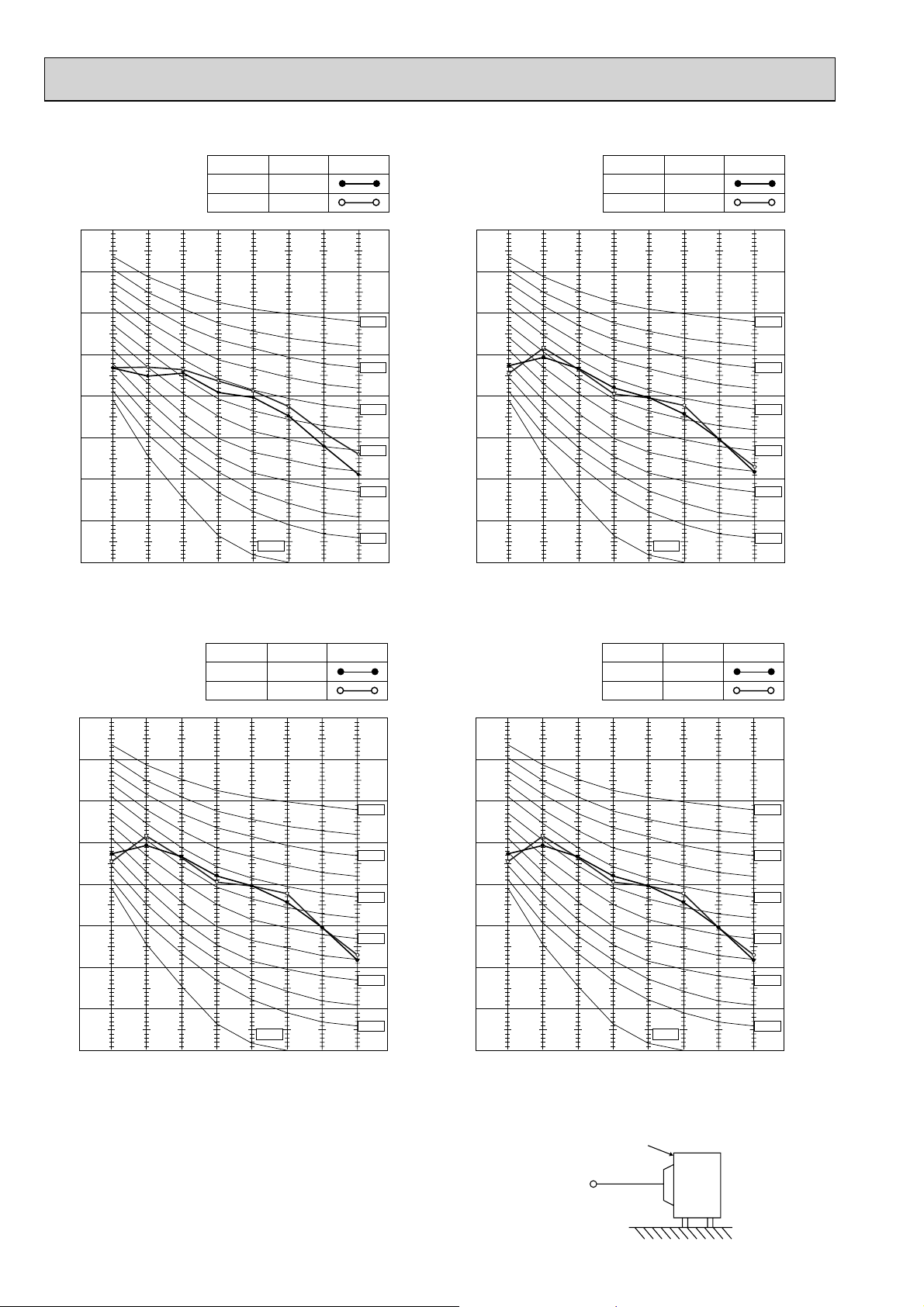
Test conditions
Cooling: Dry-bulb temperature 35°C Wet-bulb temperature (24°C)
Heating: Dry-bulb temperature 7°C Wet-bulb temperature 6°C
OUTDOOR UNIT
1 m
MICROPHONE
12
5
OBH532E
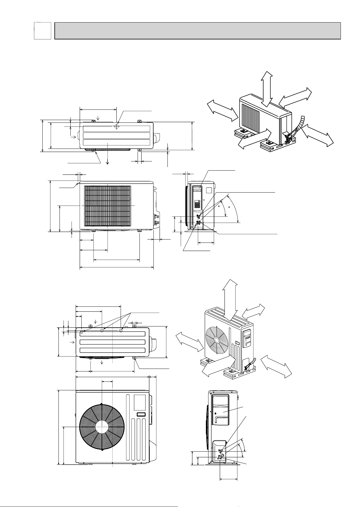
OUTLINES AND DIMENSIONS
MUZ-GE25VA MUZ-GE25VAD MUZ-GE33VA
MUZ-GE35VA MUZ-GE35VA2 MUZ-GE35VAD MUZ-GE42VA MUZ-GE42VAD
344.5
285
550
44
Air in
2 holes 10 X 21
22.3
Handle
280
10
400
Air in
Air out
150
302.5
500 Bolt pitch for installation
800
Drain hole ø42
40
69
17.5
Bolt pitch for
23
164.5
99.5
REQUIRED SPACE
100 mm or more
304~325
installation
Service panel
Liquid refrigerant pipe joint
Refrigerant pipe (flared) ø6.35
Gas refrigerant pipe joint
Refrigerant pipe (flared) ø9.52
170.5
Service port
200 mm or more
Open two sides of left,
right, or rear side.
35
43
Basically open 100 mm or more
without any obstruction in front
and on both sides of the unit.
100 mm or more
Unit: mm
350 mm or more
MUZ-GE50VA MUZ-GE50VA2 MUZ-GE50VAD
REQUIRED SPACE
515
Air in
330
850
51
430
299
66
Air in
34
Air out
121
500
840
170
Drain holes ø33
40
4 holes 10 × 21
80
100 mm or more
360
Open as a rule
500 mm or more if the back,
both sides and top are open
155
Open as a rule
500 mm or more if
the front and both
sides are open
100 mm or more
200 mm or more if
there are obstacles
to both sides
350 mm or more
Service panel
Liquid refrigerant
pipe joint
Refrigerant pipe
(flared) ø6.35
30°
35°
90
198
Gas refrigerant
pipe joint
Refrigerant pipe
(flared) ø12.7
13
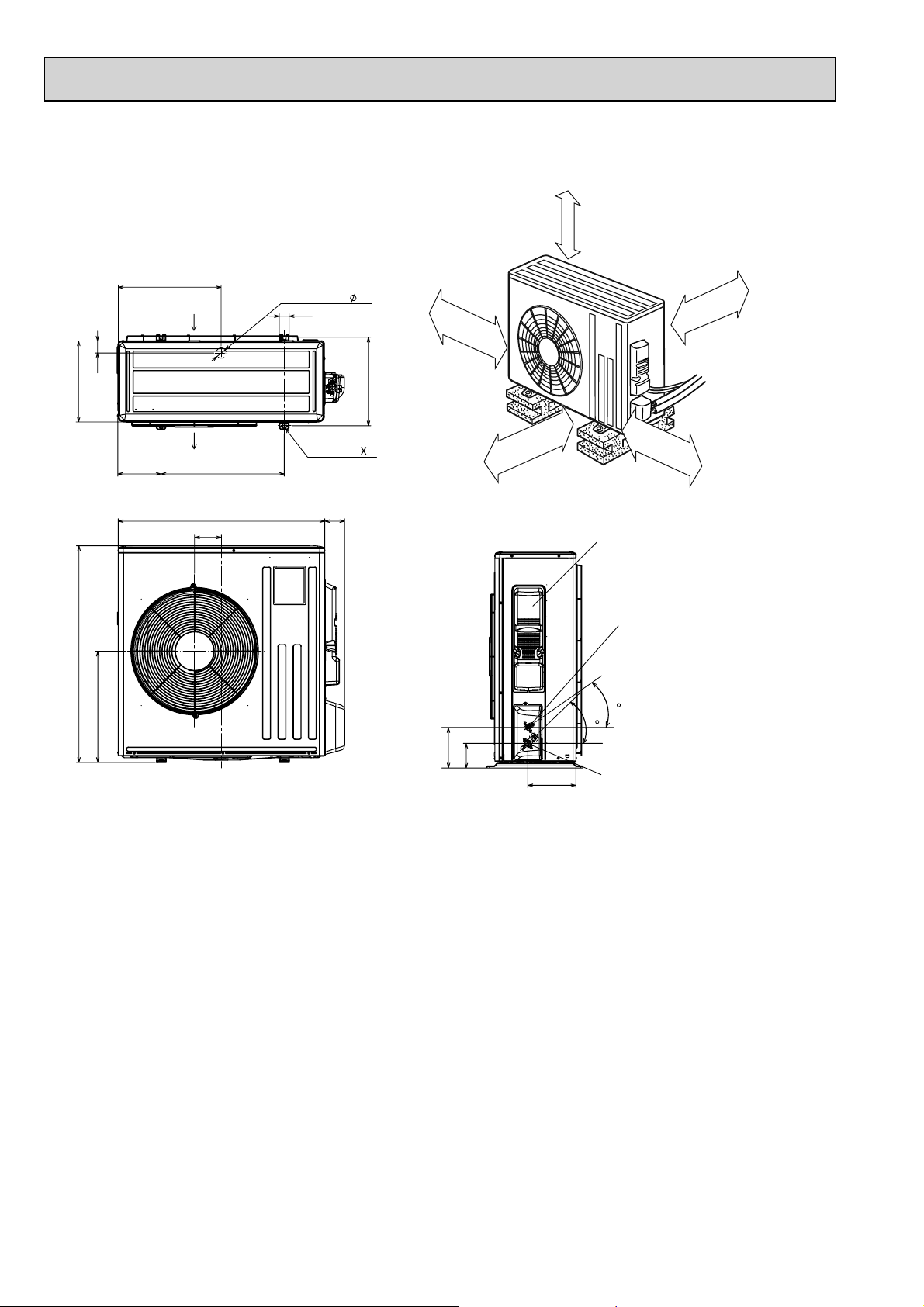
MUZ-GE60VA MUZ-GE60VAD MUZ-GE71VA MUZ-GE71VAD
OBH532E
MUZ-GE80VA MUZ-GE80VA2 MUZ-GE80VAD
Unit: mm
330
880
50
452
175
417.5
Air in
Air out
109
500
840
Drain hole
40
2-holes 10 21
81
REQUIRED SPACE
42
100 mm or more
360
500 mm or more
100 mm or more
350 mm or more
500 mm or more
Service panel
Liquid refrigerant
pipe joint
Refrigerant pipe
(flared) Ø 6.35 (MUZ-GE60)
Ø 9.52 (MUZ-GE71/80)
35
44
164.5
99.5
195
Gas refrigerant
pipe joint
Refrigerant pipe
(flared)
Ø 15.88
14
6
OBH532E
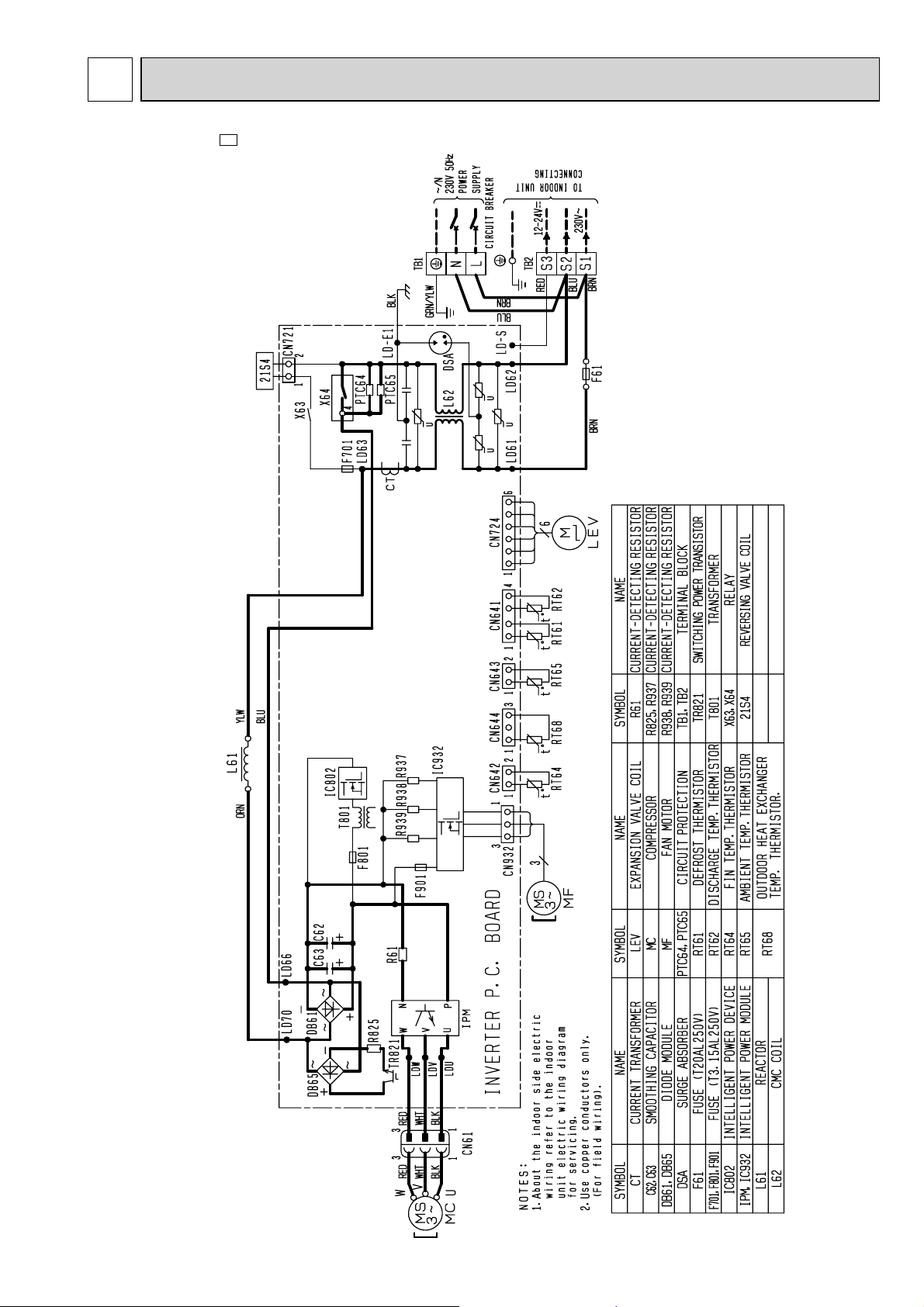
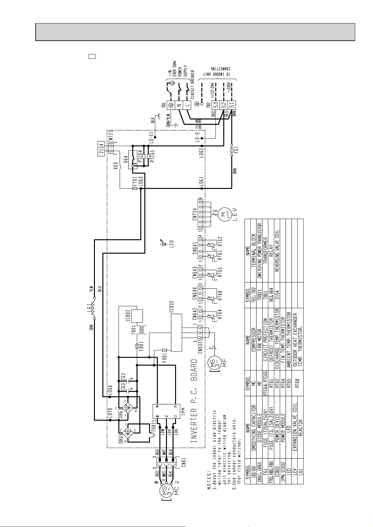
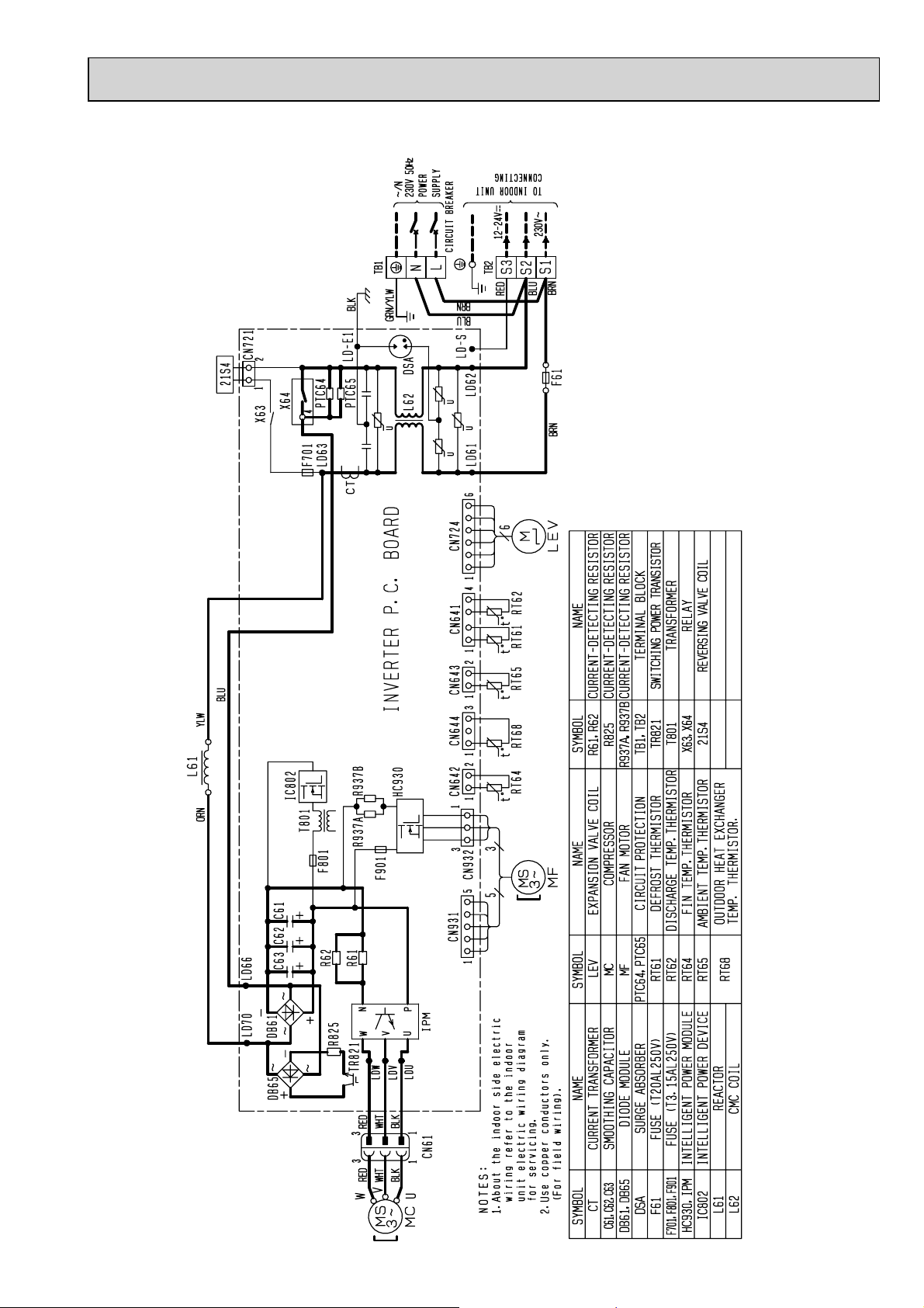
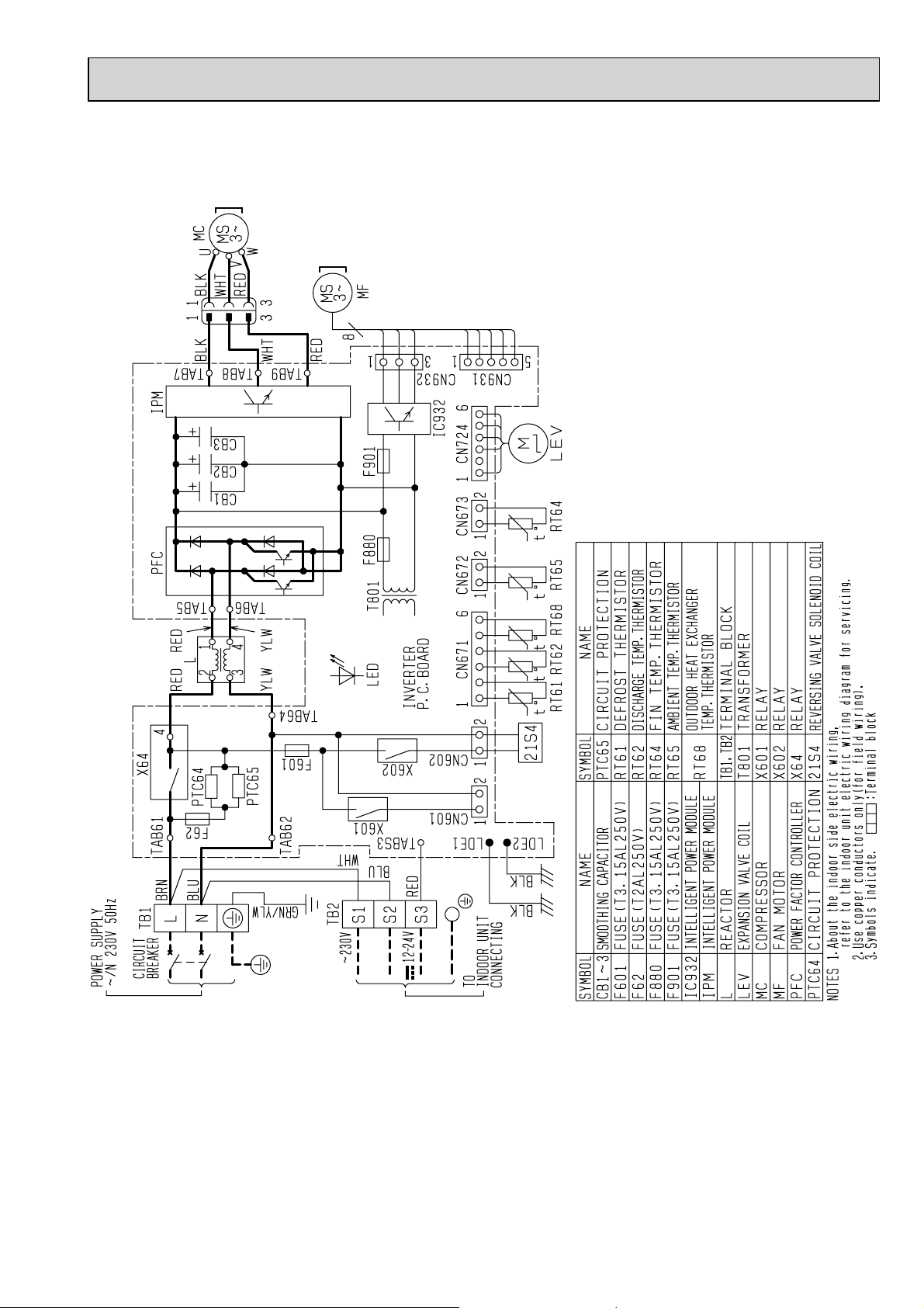
MUZ-GE25VA -A1 MUZ-GE35VA
WIRING DIAGRAM
15
MUZ-GE33VA
OBH532E
16
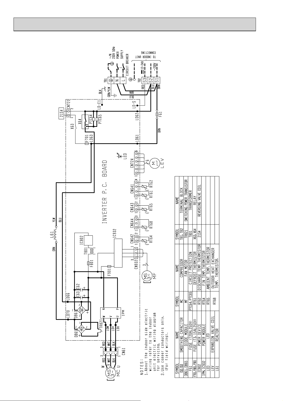
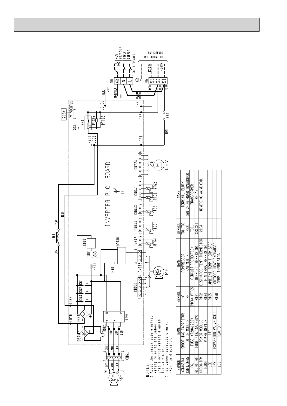
MUZ-GE25VA -A2 MUZ-GE35VA2
OBH532E
17
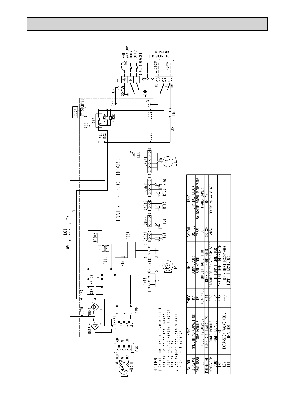
MUZ-GE25VAD MUZ-GE35VAD
OBH532E
18
MUZ-GE42VA
OBH532E
19
MUZ-GE42VAD
OBH532E
20
MUZ-GE50VA
OBH532E
21
MUZ-GE50VA2
OBH532E
22
MUZ-GE50VAD
OBH532E
23
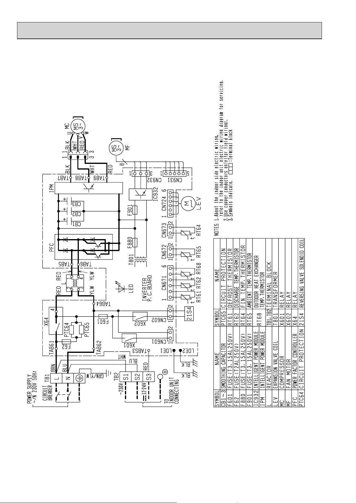
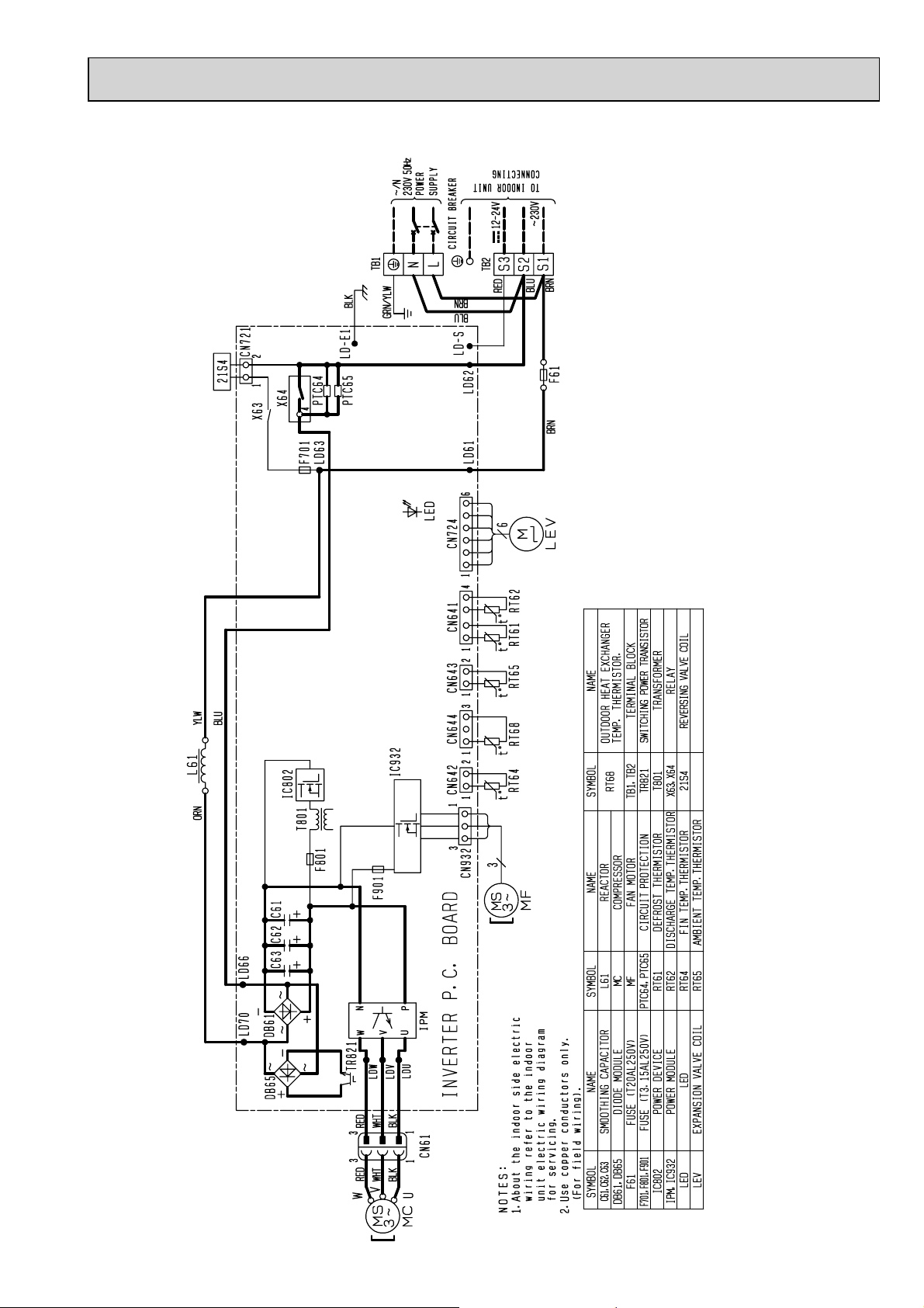
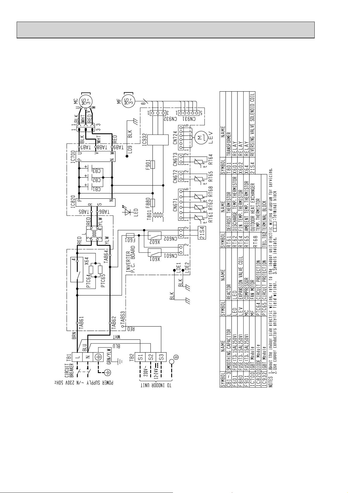
MUZ-GE60VA MUZ-GE71VA MUZ-GE80VA
OBH532E
24
MUZ-GE80VA2
OBH532E
25
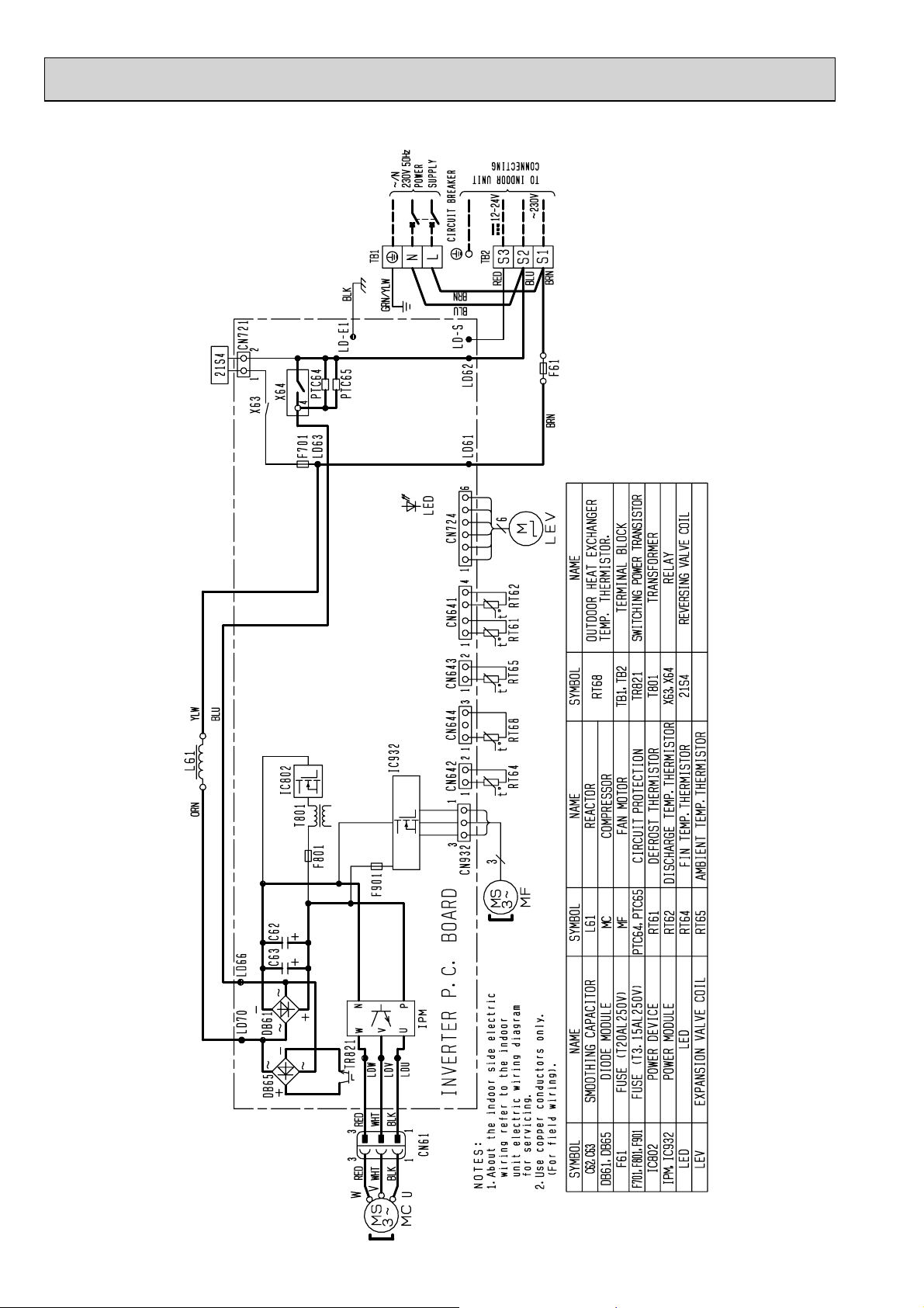
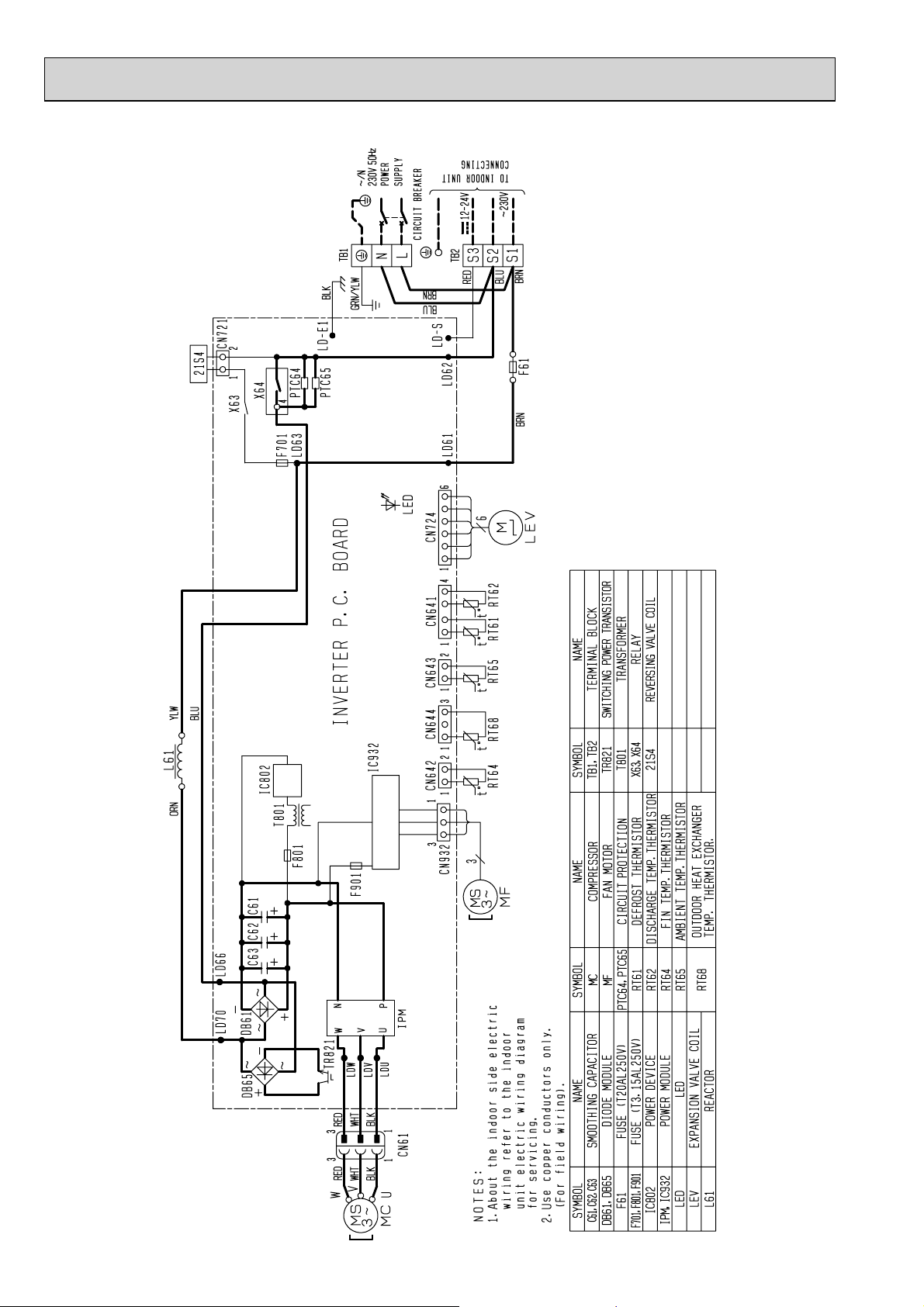
MUZ-GE60VAD MUZ-GE71VAD MUZ-GE80VAD
OBH532E
26
7
OBH532E
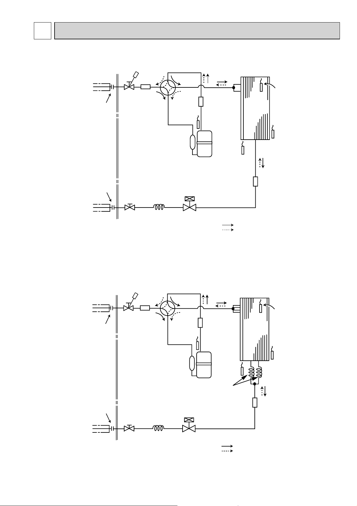
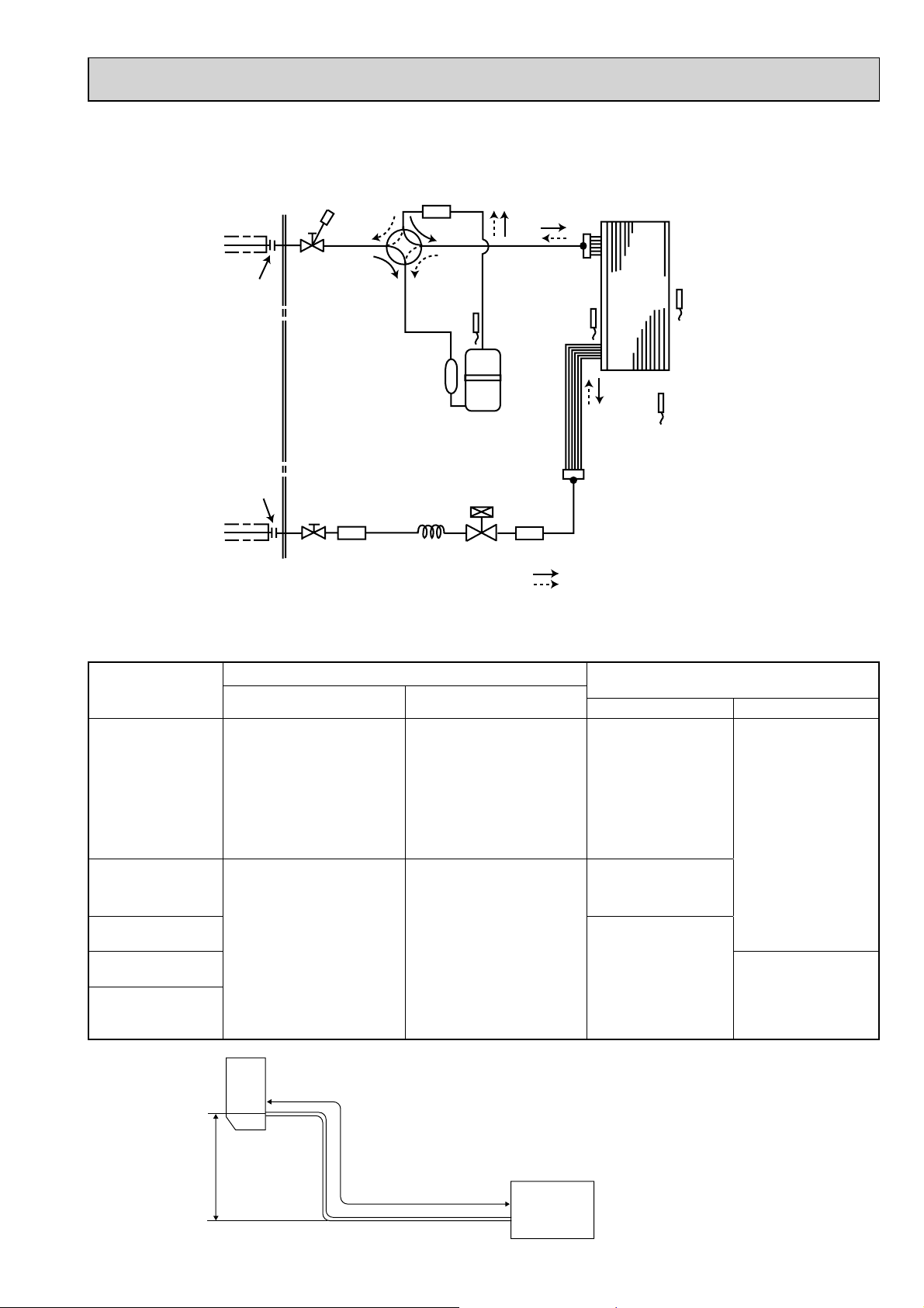
REFRIGERANT SYSTEM DIAGRAM
MUZ-GE25VA MUZ-GE25VAD MUZ-GE33VA MUZ-GE35VA
Refrigerant pipe ø9.52
(with heat insulator)
Flared connection
Flared connection
Refrigerant pipe ø6.35
(with heat insulator)
Muffler
Stop valve
(with service port)
Capillary tube
ø3.0×ø2.0×240
Stop valve
(with strainar)
4-way valve
Discharge
temperature
thermistor
RT62
LEV
Muffler
Compressor
Defrost
thermistor
RT61
Refrigerant flow in cooling
Refrigerant flow in heating
Outdoor
heat
exchanger
Strainer
#100
R.V. coil
heating ON
cooling OFF
Outdoor heat
exchanger
temperature
thermistor
RT68
Ambient
temperature
thermistor
RT65
Unit: mm
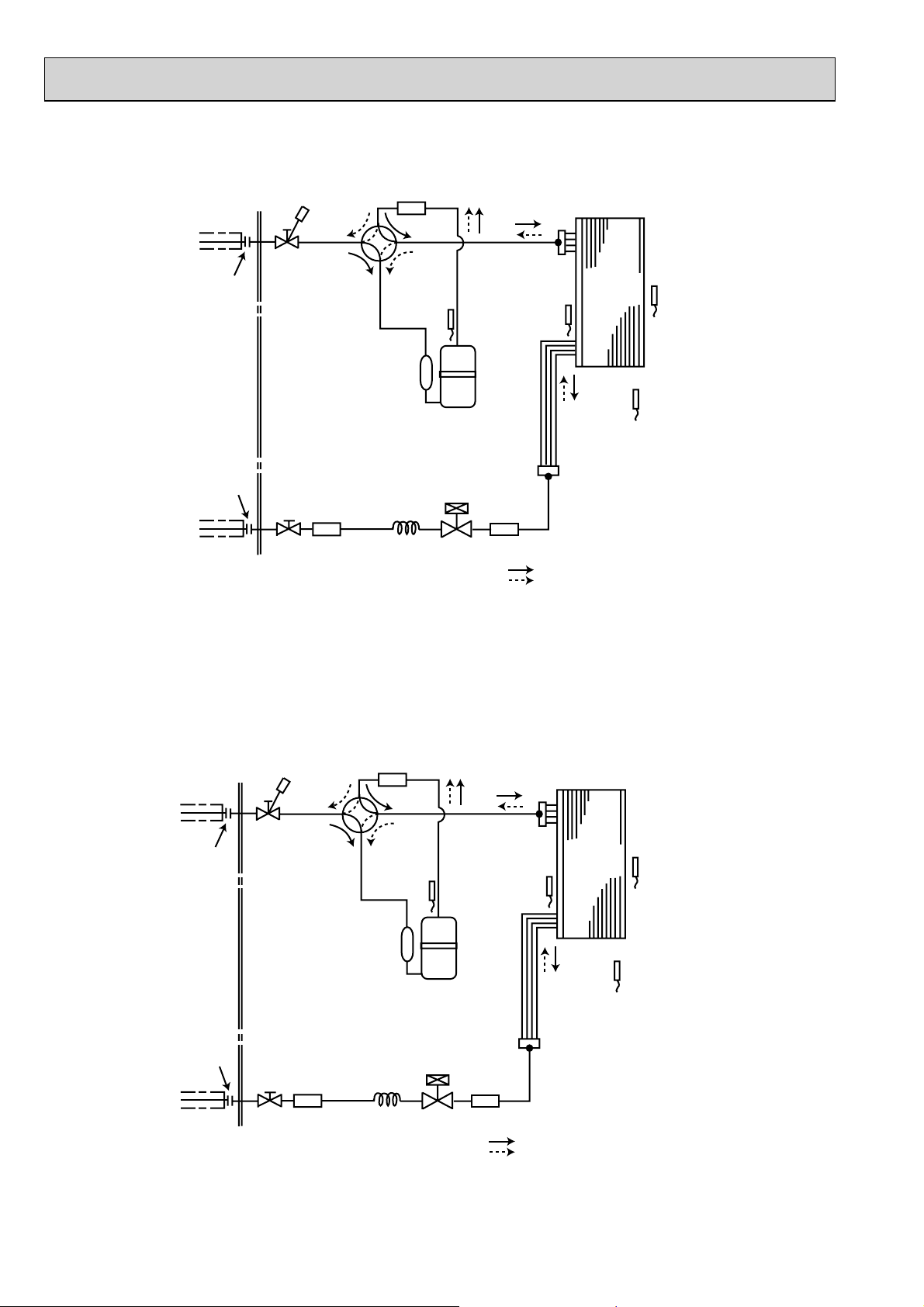
MUZ-GE35VA2 MUZ-GE35VAD MUZ-GE42VA MUZ-GE42VAD
Refrigerant pipe ø9.52
(with heat insulator)
Flared connection
Flared connection
Refrigerant pipe ø6.35
(with heat insulator)
Muffler
Stop valve
(with service port)
Capillary tube
ø3.0×ø2.0×240
Stop valve
(with strainar)
4-way valve
Discharge
temperature
thermistor
RT62
LEV
Muffler
Compressor
Defrost
thermistor
RT61
Capillary tube
ø3.0×ø1.8×600(×2)
Refrigerant flow in cooling
Refrigerant flow in heating
Outdoor
heat
exchanger
Outdoor heat
exchanger
temperature
thermistor
RT68
Ambient
temperature
thermistor
RT65
Strainer
#100
R.V. coil
heating ON
cooling OFF
27
MUZ-GE50VA MUZ-GE50VA2 MUZ-GE50VAD
OBH532E
Unit: mm
Refrigerant pipe
(with heat insulator)
Flared connection
Flared connection
Refrigerant pipe ø6.35
(with heat insulator)
ø
12.7
4-way valve
Stop valve
(with service port)
Receiver
Stop valve
(with strainar)
Muffler
#100
Discharge
temperature
thermistor
RT62
Compressor
Capillary tube
ø
3.6
×
ø
2.4×50
LEV
Defrost
thermistor
RT61
Strainer
#100
Outdoor
heat
exchanger
Outdoor heat
exchanger
temperature
thermistor
RT68
R.V. coil
heating ON
cooling OFF
Refrigerant flow in cooling
Refrigerant flow in heating
Ambient
temperature
thermistor
RT65
MUZ-GE60VA MUZ-GE60VAD
Refrigerant pipe
(with heat insulator)
Flared connection
Flared connection
Refrigerant pipe ø6.35
(with heat insulator)
ø
15.88
Stop valve
Stop valve
(with service port)
Strainer
#100
4-way valve
Capillary tube
ø
Muffler
#100
Discharge
temperature
thermistor
RT62
4.0
×
ø
2.4×100
Compressor
LEV
Defrost
thermistor
RT61
Strainer
#100
Outdoor
heat
exchanger
Outdoor heat
exchanger
temperature
thermistor
RT68
R.V. coil
heating ON
cooling OFF
Refrigerant flow in cooling
Refrigerant flow in heating
Ambient
temperature
thermistor
RT65
28
MUZ-GE71VA MUZ-GE71VAD
OBH532E
MUZ-GE80VA MUZ-GE80VA2 MUZ-GE80VAD
Refrigerant pipe
(with heat insulator)
Flared connection
ø
15.88
Stop valve
(with service port)
4-way valve
Muffler
#100
Discharge
temperature
thermistor
RT62
Defrost
thermistor
RT61
Outdoor
heat
exchanger
Ambient
temperature
thermistor
RT65
Unit: mm
Flared connection
Refrigerant pipe ø9.52
(with heat insulator)
Strainer
#100
Stop valve
Compressor
Capillary tube
ø
4.0
×
ø
2.4×100
LEV
Strainer
#100
Outdoor heat
exchanger
temperature
thermistor
RT68
R.V. coil
heating ON
cooling OFF
Refrigerant flow in cooling
Refrigerant flow in heating
MAX. REFRIGERANT PIPING LENGTH and MAX. HEIGHT DIFFERENCE
MUZ-GE25VA
MUZ-GE25VAD
MUZ-GE33VA
MUZ-GE35VA
MUZ-GE35VA2
MUZ-GE35VAD
MUZ-GE42VA
MUZ-GE42VAD
MUZ-GE50VA
MUZ-GE50VA2
MUZ-GE50VAD
MUZ-GE60VA
MUZ-GE60VAD
MUZ-GE71VA
MUZ-GE71VAD
MUZ-GE80VA
MUZ-GE80VA2
MUZ-GE80VAD
Refrigerant piping: m
Max. Length
A
Max. Height difference
B
20 12 9.52
30 15
Piping size O.D: mm
Gas Liquid
12.7
15.88
6.35
9.52
Indoor
unit
Max. Height
difference
B
Max. Length
A
Outdoor unit
29

ADDITIONAL REFRIGERANT CHARGE (R410A: g)
OBH532E
Model
MUZ-GE25VA
MUZ-GE25VAD
MUZ-GE33VA
MUZ-GE35VA
MUZGE35VA2
MUZGE35VAD
MUZ-GE42VA
Outdoor unit
precharged
800
1,150
5 m 6 m 7 m 8 m 9 m 10 m 11 m 12 m 13 m 14 m 15 m 20 m
0 0 0 30 60 90 120 150 180 210 240 390
MUZ-GE42VAD
Calculation: X g = 30 g/m × (Refrigerant piping length (m) - 7)
Model
MUZ-GE50VA
MUZ-GE50VA2
MUZ-GE50VAD
Calculation: X g = 20 g/m × (Refrigerant piping length (m) – 7)
Model
MUZ-GE60VA
MUZ-GE60VAD
Calculation: X g = 20 g/m × (Refrigerant piping length (m) – 10)
Model
MUZ-GE71VA
MUZ-GE71VAD
MUZ-GE80VA
MUZ-GE80VA2
MUZ-GE80VAD
Calculation: X g = 55 g/m × (Refrigerant piping length (m) – 10)
NOTE: Refrigerant piping exceeding 7 m (MUZ-GE25/33/35/42/50) or 10 m (MUZ-GE60/71/80) requires additional
refrigerant charge according to the calculation.
Outdoor unit
precharged
1,550 0 60 160 260 360 460
Outdoor unit
precharged
1,550 0 0 100 200 300 400
Outdoor unit
precharged
1,900 0 0 275 550 825 1,100
7 m 10 m 15 m 20 m 25 m 30 m
7 m 10 m 15 m 20 m 25 m 30 m
7 m 10 m 15 m 20 m 25 m 30 m
Refrigerant piping length (one way)
Refrigerant piping length (one way)
Refrigerant piping length (one way)
Refrigerant piping length (one way)
30

PERFORMANCE CURVES8
OBH532E
MUZ-GE25VA MUZ-GE25VAD MUZ-GE33VA MUZ-GE35VA MUZ-GE35VA2 MUZ-GE35VAD
MUZ-GE42VA MUZ-GE42VAD MUZ-GE50VA MUZ-GE50VA2 MUZ-GE50VAD
MUZ-GE60VA MUZ-GE60VAD MUZ-GE71VA MUZ-GE71VAD
MUZ-GE80VA MUZ-GE80VA2 MUZ-GE80VAD
The standard specifications apply only to the operation of the air conditioner under normal conditions. Since operating conditions vary according to the areas where these units are installed, the following information has been provided to clarify the
operating characteristics of the air conditioner under the conditions indicated by the performance curve.
(1) GUARANTEED VOLTAGE
198 ~ 264 V, 50 Hz
(2) AIR FLOW
Air flow should be set at MAX.
(3) MAIN READINGS
(1) Indoor intake air wet-bulb temperature: °C [WB]
(2) Indoor outlet air wet-bulb temperature: °C [WB]
(3) Outdoor intake air dry-bulb temperature: °C [DB]
(4) Total input: W
(5) Indoor intake air dry-bulb temperature: °C [DB]
(7) Total input: W
Indoor air wet and dry bulb temperature difference on the left side of the following chart shows the difference between the
indoor intake air wet and dry bulb temperature and the indoor outlet air wet and dry bulb temperature for your reference at
service.
}
}
Cooling
Heating(6) Outdoor intake air wet-bulb temperature: °C [WB]
How to measure the indoor air wet and dry bulb temperature difference
1.
Attach at least 2 sets of wet and dry bulb thermometers to the indoor air intake as shown in the figure, and at least 2 sets of wet
and dry bulb thermometers to the indoor air outlet. The thermometers must be attached to the position where air speed is high.
2. Attach at least 2 sets of wet and dry bulb thermometers to the outdoor air intake.
Cover the thermometers to prevent direct rays of the sun.
3. Check that the air filter is cleaned.
4. Open windows and doors of room.
5. Press the EMERGENCY OPERATION switch once (twice) to start the EMERGENCY COOL (HEAT) MODE.
6. When system stabilizes after more than 15 minutes, measure temperature and take an average temperature.
7. 10 minutes later, measure temperature again and check that the temperature does not change.
INDOOR UNIT OUTDOOR UNIT
Wet and dry bulb
thermometers
FRONT VIEW
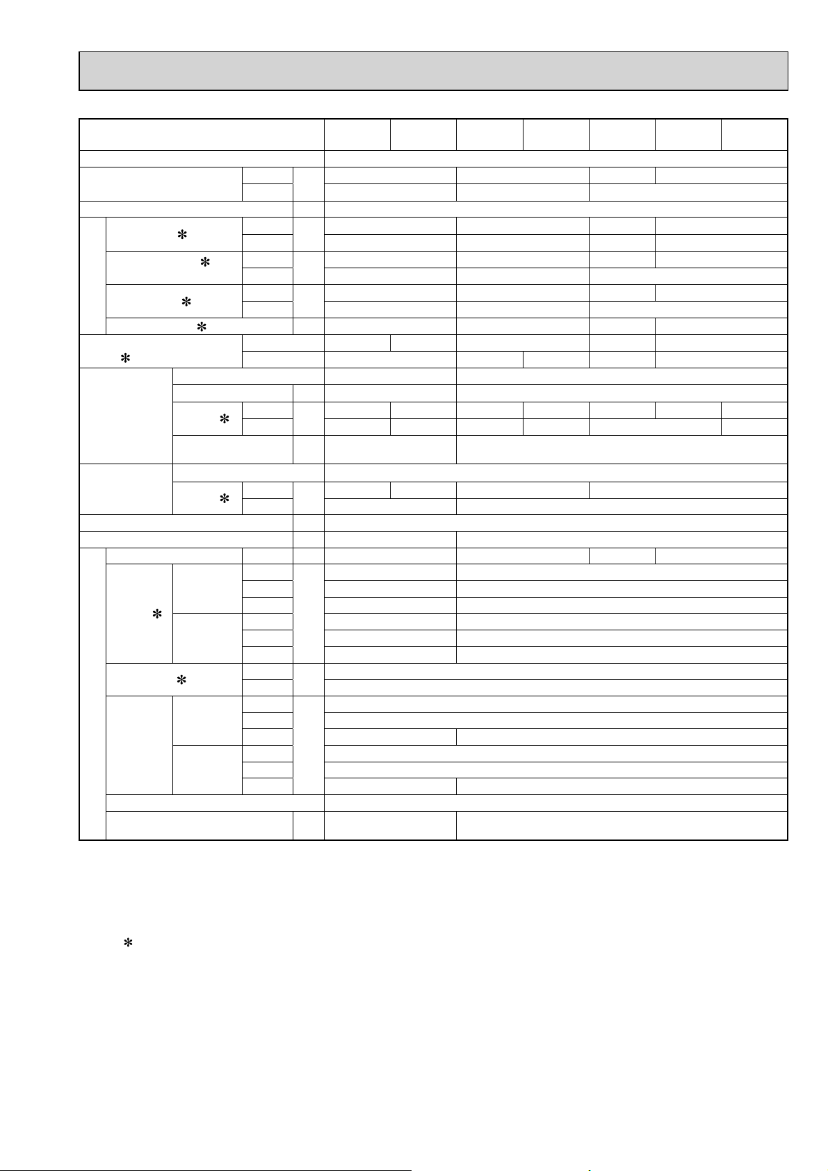
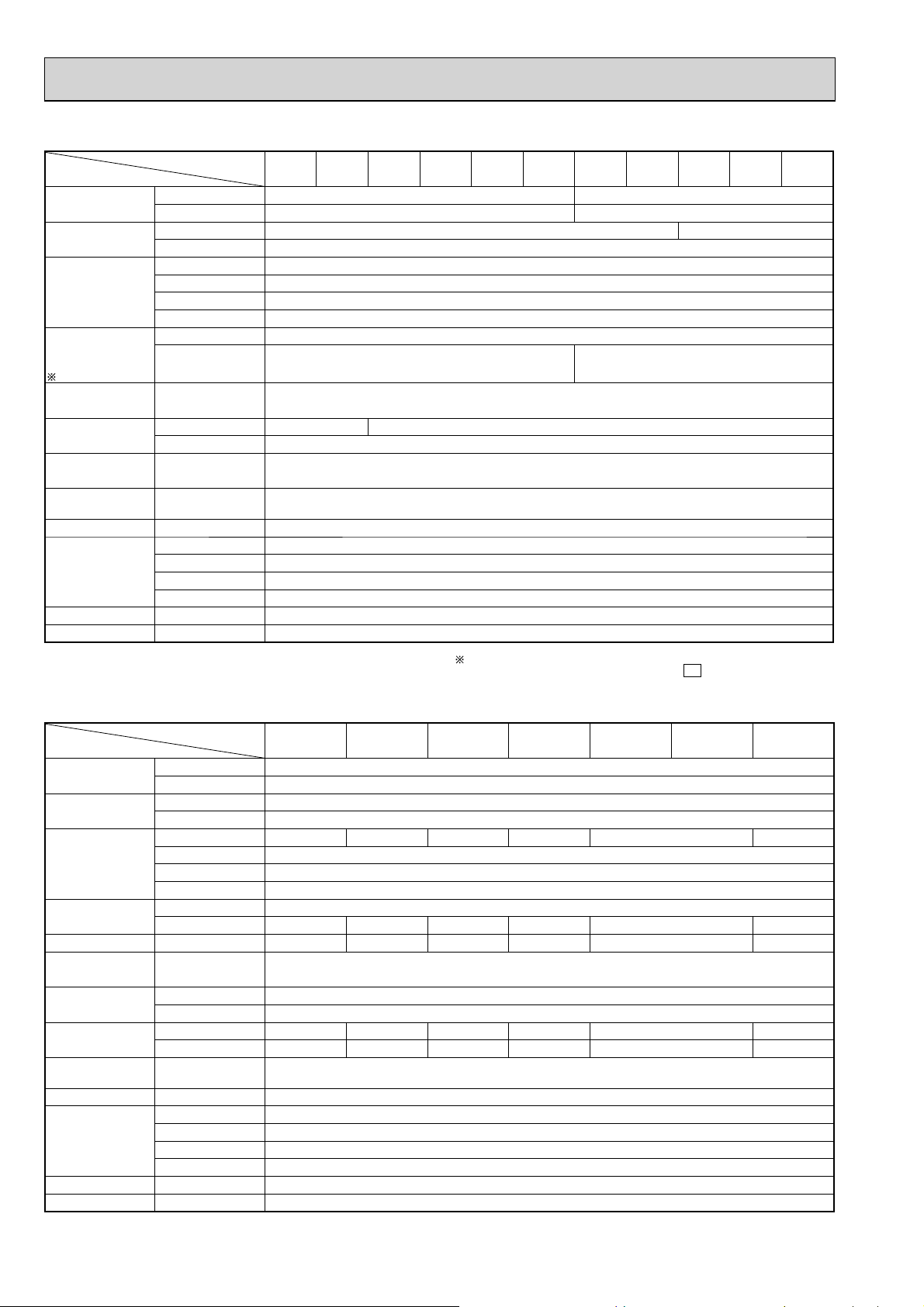
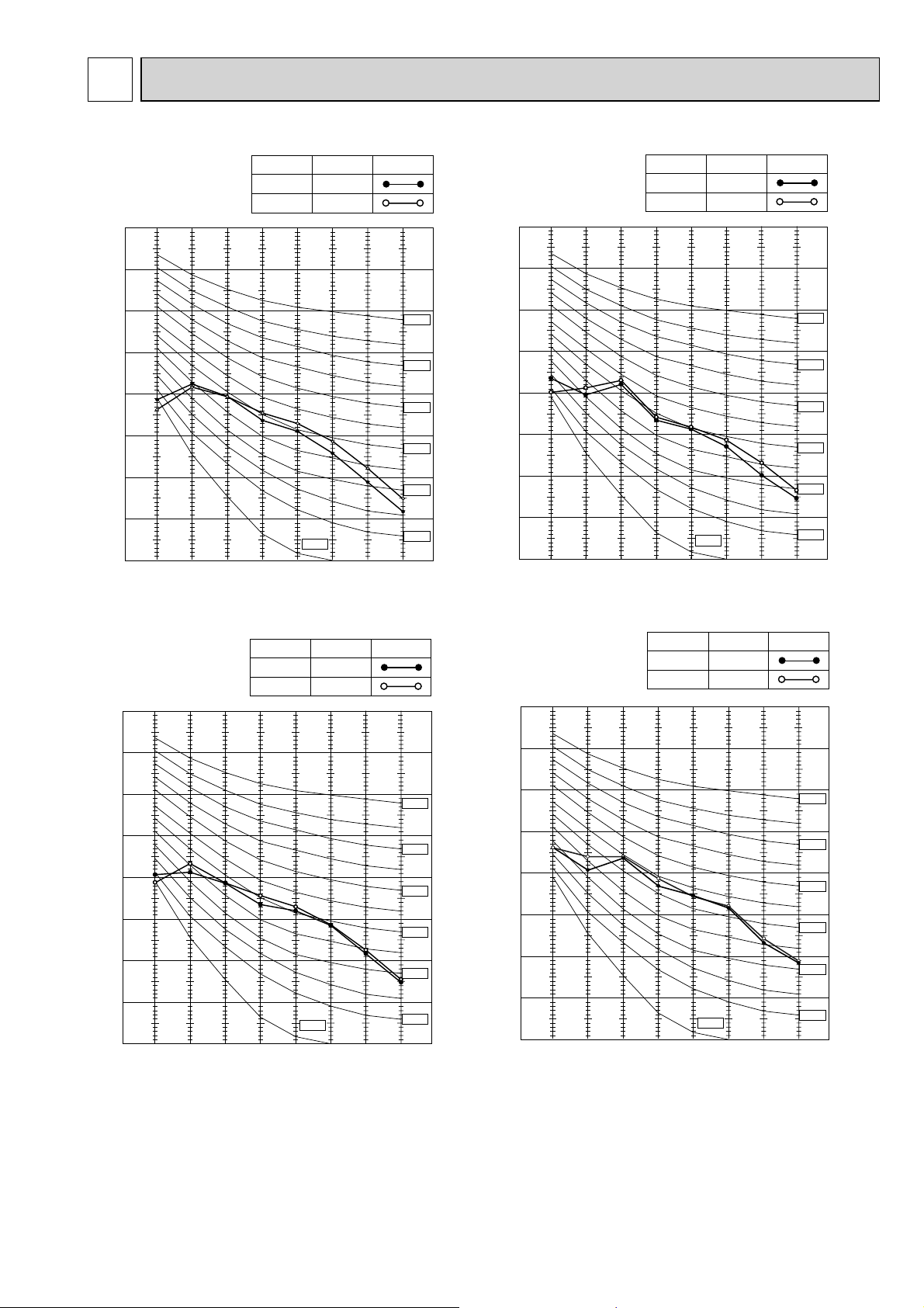
8-1. CAPACITY AND INPUT CURVES
10.2
9.4
8.6
7.9
7.1
6.4
5.7
9.7
9.0
8.2
7.5
6.8
6.1
5.4
9.3
8.6
7.9
7.2
6.5
5.8
5.2
6.6
7.8
8.4
6.1
7.2
7.7
5.6
6.6
7.1
5.1
6.0
6.5
4.6
5.5
4.9
4.4
5.9
5.3
4.7
difference (°C)
4.2
3.7
Indoor air Wet-bulb temperature
10.4
9.5
8.7
8.0
7.2
6.5
5.7
9.0
8.3
7.6
6.9
6.3
5.6
5.0
10.4
9.5
8.7
8.0
7.2
6.5
5.7
10.1
9.3
8.5
7.7
7.0
6.3
5.6
Wet and dry bulb
thermometers
BACK VIEW
1.5
Cooling capacity (
1.4
1.3
1.2
1.1
1.0
Capacity correction factors
0.9
-10-5 0 5 1015202530354045
Outdoor intake air Dry-bulb temperature(°C)
at Rated frequency)
Indoor intake air Wet-bulb
temperature( )
26
24
22
20
18
MUZ-GE33VA
MUZ-GE35VA
MUZ-GE35VA2
MUZ-GE25VA
MUZ-GE25VAD
MUZ-GE35VAD
MUZ-GE42VA
MUZ-GE42VAD
MUZ-GE50VA
MUZ-GE50VA2
MUZ-GE50VAD
MUZ-GE60VA
MUZ-GE60VAD
MUZ-GE80VA
MUZ-GE80VA2
MUZ-GE71VA
MUZ-GE71VAD
MUZ-GE80VAD
31

7.1
OBH532E
6.6
5.6
6.0
5.1
5.5
4.6
4.9
4.2
difference (°C)
4.4
3.7
3.9
3.3
Indoor air Wet-bulb temperature
MUZ-GE25VA
MUZ-GE25VAD
MUZ-GE33VA
18.2
16.8
15.4
14.0
12.6
11.2
9.8
8.4
difference (°C)
7.0
5.6
Indoor air Dry-bulb temperature
22.7
21.0
19.2
17.5
15.7
14.0
12.2
10.5
8.7
7.0
6.5
5.9
5.3
4.7
4.1
MUZ-GE35VA
MUZ-GE35VA2
MUZ-GE35VAD
8.7
8.0
7.2
6.5
5.7
5.0
MUZ-GE42VA
27.0
24.9
22.8
20.7
18.7
16.6
14.5
12.4
10.4
8.3
MUZ-GE42VAD
8.6
7.9
7.1
6.4
5.7
5.0
MUZ-GE50VA
26.2
24.1
22.1
20.1
18.1
16.1
14.1
12.1
10.1
8.0
8.2
7.5
6.8
6.1
5.4
4.8
MUZ-GE50VA2
MUZ-GE50VAD
7.9
7.2
6.5
5.8
5.2
4.6
MUZ-GE60VA
20.0
18.5
16.9
15.4
13.9
12.3
10.8
9.2
7.7
6.2
MUZ-GE60VAD
7.6
6.9
6.3
5.6
5.0
4.4
MUZ-GE71VA
23.8
21.9
20.1
18.3
16.4
14.6
12.8
11.0
MUZ-GE71VAD
9.1
7.3
8.7
8.0
7.2
6.5
5.7
5.0
Total input (Cooling :
8.5
7.7
7.0
6.3
5.6
4.9
MUZ-GE80VA
1.3
1.2
1.1
1.0
0.9
Input correction factors
0.8
-10-5 0 5 1015202530354045
MUZ-GE80VA2
MUZ-GE80VAD
Outdoor intake air Dry-bulb temperature (°C)
Heating capacity (
26.4
24.4
22.3
20.3
18.3
16.2
14.2
12.2
10.2
1.3
1.2
1.1
1.0
0.9
0.8
0.7
0.6
0.5
Capacity correction factor
8.1
0.4
-20 -15 -10 -5 0 5 10 15
Indoor intake air Dry-bulb temperature ( )
Outdoor intake air Wet-bulb temperature (°C)
at Rated frequency
Indoor intake air Wet-bulb
temperature( )
at Rated frequency)
)
22
26
24
20
18
15
20
26
MUZ-GE50VA
MUZ-GE50VA2
26.2
24.1
22.1
20.1
18.1
16.1
14.1
12.1
10.1
8.0
MUZ-GE50VA
MUZ-GE50VA2
MUZ-GE50VAD
MUZ-GE50VAD
20.0
18.5
16.9
15.4
13.9
12.3
10.8
9.2
7.7
6.2
MUZ-GE60VA
MUZ-GE80VA
MUZ-GE80VA2
MUZ-GE71VA
MUZ-GE60VAD
MUZ-GE60VAD
23.8
21.9
20.1
18.3
16.4
14.6
12.8
11.0
9.1
7.3
MUZ-GE71VAD
MUZ-GE71VA
MUZ-GE71VAD
MUZ-GE60VA
MUZ-GE80VAD
26.4
24.4
22.3
20.3
18.3
16.2
14.2
12.2
10.2
MUZ-GE80VA
1.3
1.2
1.1
1.0
0.9
0.8
0.7
0.6
Input correction factor
0.5
8.1
0.4
-20 -15 -10 -5 0 5 10 15
MUZ-GE80VA2
MUZ-GE80VAD
Total input (Heating :
Indoor intake air Dry-bulb temperature ( )
Outdoor intake air Wet-bulb temperature (°C)
at Rated frequency
)
MUZ-GE33VA
MUZ-GE35VA
MUZ-GE35VA2
MUZ-GE35VAD
MUZ-GE25VA
MUZ-GE25VAD
18.2
22.7
16.8
21.0
15.4
19.2
14.0
17.5
12.6
15.7
11.2
14.0
9.8
12.2
8.4
7.0
5.6
10.5
8.7
7.0
MUZ-GE25VA
MUZ-GE25VAD
MUZ-GE33VA
difference (°C)
Indoor air Dry-bulb temperature
MUZ-GE42VA
27.0
24.9
22.8
20.7
18.7
16.6
14.5
12.4
10.4
8.3
MUZ-GE42VA
MUZ-GE35VA
MUZ-GE35VA2
MUZ-GE35VAD
MUZ-GE42VAD
MUZ-GE42VAD
NOTE: The above broken lines are for the heating operation without any frost and defrost operation.
26
20
15
32
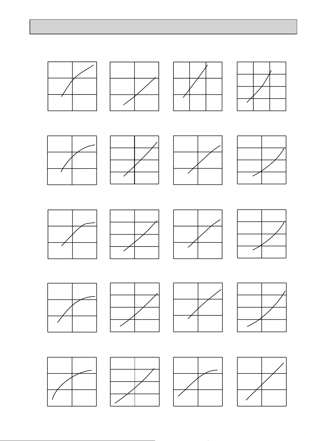
8-2. CAPACITY AND INPUT CORRECTION BY OPERATIONAL FREQUENCY OF COMPRESSOR
OBH532E
MUZ-GE25VA MUZ-GE25VAD
Correction of Cooling capacity
1.5
Correction of Cooling input
3.0
Correction of Heating capacity
1.5
Corr ect ion of Heating input
2.0
1.0
0.5
Capacity cor rection f actor s
0.0
050100
The operational frequency
of compressor (Hz)
MUZ-GE33VA
Correction o f Cooling capa city
1.5
1.0
0.5
Capacity cor rection f actor s
0.0
050100
The operational frequency
of compressor (Hz)
MUZ-GE35VA
Correction o f Cooling capa city
1.5
1.0
0.5
Capacity cor rection f actor s
0.0
050100
The operational frequency
of compressor (Hz)
MUZ-GE35VA2 MUZ-GE35VAD
Correction of Cooling capacity
1.5
Input correction factors
2.0
1.0
0.0
0 50 100
The operational frequency
of compressor (Hz)
Correction of C ooling input
2.0
1.5
1.0
0.5
Input cor rection f actor s
0.0
0 50 100
The operational frequency
of compressor (Hz)
Correction of C ooling input
2.0
1.5
1.0
0.5
Input correction factors
0.0
0 50 100
The operational frequency
of compressor (Hz)
Correction of Cooling input
2.0
1.0
0.5
Capacity correction factors
0.0
050100150
The operational frequency
of compressor (Hz)
Correction of Heating capacity
1.5
1.0
0.5
Capacity correction factors
0.0
0 50 100
The operational frequency
of compressor (Hz)
Correction of Heating capacity
1.5
1.0
0.5
Capacity cor rection fac tors
0.0
0 50 100
The operational frequency
of compressor (Hz)
Correction of Heating capacity
1.5
1.5
1.0
0.5
Input correction factors
0.0
0 50 100 150
The operational frequency
of compressor (Hz)
Correction of Heating input
2.0
1.5
1.0
0.5
Input correction factors
0.0
050100
The operational frequency
of compressor (Hz)
Correction of Heating input
2.0
1.5
1.0
0.5
Input correction factors
0.0
050100
The operational frequency
of compressor (Hz)
Correction of Heating input
2.0
1.0
0.5
Capacity correction factors
0.0
0 50 100
The oper ationa l f requency
of compressor (Hz)
MUZ-GE42VA MUZ-GE42VAD
Correction of Cooling capacity
1.5
1.0
0.5
Capacity correction factors
0.0
0 50 100
The oper ationa l f requency
of compressor (Hz)
1.5
1.0
0.5
Input correction factors
0.0
0 50 100
The oper ationa l f requency
of compressor (Hz)
Correction of Cooling input
2.0
1.5
1.0
0.5
Input correction factors
0.0
0 50 100
The oper ationa l f requency
of compressor (Hz)
1.0
0.5
Capacity correction factors
0.0
0 50 100
The operational frequency
of compressor (Hz)
Correction of Heating capacity
1.5
1.0
0.5
Capacity correction factors
0.0
0 50 100
The operational frequency
of compressor (Hz)
33
1.5
1.0
0.5
Capacity correction factors
0.0
050100
The operational frequency
of compressor (Hz)
Correction of Heating input
1.5
1.0
0.5
Capacity correction factors
0.0
050100
The operational frequency
of compressor (Hz)

MUZ-GE50VA
OBH532E
Correction of Cooling capacity
1.5
Correction of Cooling input
1.5
Correction of Heating capacity
1.5
Correction of Heating input
2.0
1.0
0.5
Capacity correction factors
0.0
0 50 100
The operational frequency
of compressor (Hz)
MUZ-GE50VA2 MUZ-GE50VAD
Correction of Cooling capacity
1.5
1.0
0.5
Capacity correction factors
0.0
0 50 100
The operational frequency
of compressor (Hz)
MUZ-GE60VA MUZ-GE60VAD
Correction of Cooling capacity
2.0
1.5
1.0
0.5
Input correction factors
0.0
050100
The operational frequency
of compressor (Hz)
Correction of Cooling input
2.0
1.5
1.0
0.5
Input correction factors
0.0
0 50 100
The oper ationa l f requency
of compressor (Hz)
Correction of Cooling input
2.0
1.5
1.0
0.5
Capacity correction factors
0.0
1.5
1.0
0.5
Capacity correction factors
0.0
2.0
1.5
1.5
1.0
0.5
Capacity correction factors
050100
The operational frequency
of compressor (Hz)
Correction of Heating capacity
050100
The operational frequency
of compressor (Hz)
Correction of Heating capacity
0.0
050100
The operational frequency
of compressor (Hz)
Correction of Heating input
2.0
1.5
1.0
0.5
Capacity correction factors
0.0
050100
The operational frequency
of compressor (Hz)
Correction of Heating input
2.0
1.5
1.0
0.5
Capacity correction factors
0.0
0 50 100 150
The operational frequency
of compressor (Hz)
MUZ-GE71VA MUZ-GE71VAD
Correction of Cooling capacity
2.0
1.5
1.0
0.5
Capacity correction factors
0.0
0 50 100 150
The oper ationa l f requency
of compressor (Hz)
MUZ-GE80VA
Correction of Cooling capacity
2.0
1.5
1.0
1.0
0.5
Input correction factors
0.0
0 50 100 150
The oper ationa l f requency
of compressor (Hz)
Correction of Cooling input
2.0
1.5
1.0
0.5
Input correction factors
0.0
0 50 100 150
The operational frequency
of compressor (Hz)
Correction of Cooling input
2.0
1.5
1.0
1.0
0.5
Capacity correction factors
0.0
0 50 100 150
The oper ationa l f requency
of compressor (Hz)
Correction of Heating capacity
2.0
1.5
1.0
0.5
Capacity correction factors
0.0
0 50 100 150
The operational frequency
of compressor (Hz)
Correction of Heating capacity
2.0
1.5
1.0
1.0
0.5
Capacity correction factors
0.0
0 50 100 150
The operational frequency
of compressor (Hz)
Correction of Heating input
2.0
1.5
1.0
0.5
Capacity correction factors
0.0
0 50 100 150
The oper ationa l f requency
of compressor (Hz)
Correction of Heating input
2.0
1.5
1.0
0.5
Capacity correction factors
0.0
0 50 100 150
The oper ationa l f requency
of compressor (Hz)
0.5
Input correction factors
0.0
0 50 100 150
The operational frequency
of compressor (Hz)
0.5
Capacity correction factors
0.0
0 50 100 150
The operational frequency
of compressor (Hz)
34
0.5
Capacity correction factors
0.0
0 50 100 150
The oper ationa l f requency
of compressor (Hz)

MUZ-GE80VA2 MUZ-GE80VAD
OBH532E
Correction of Cooling capacity
2.0
2.0
Correction of Cooling input
Correction of Heating capacity
2.0
Correction of Heating input
2.0
1.5
1.0
0.5
Capacity correction factors
0.0
0 50 100 150
The oper ationa l f requency
of compressor (Hz)
1.5
1.0
0.5
Input correction factors
0.0
0 50 100 150
The oper ationa l f requency
of compressor (Hz)
1.5
1.0
0.5
Capacity correction factors
0.0
0 50 100 150
The operational frequency
of compressor (Hz)
1.5
1.0
0.5
Capacity correction factors
0.0
050100150
The oper ationa l f requency
of compressor (Hz)
8-3. TEST RUN OPERATION (How to operate fixed-frequency operation)
1. Press EMERGENCY OPERATION switch to start COOL or HEAT mode (COOL: Press once, HEAT: Press twice).
2. Test run operation starts and continues to operate for 30 minutes.
3.
Compressor operates at rated frequency in COOL mode or 58 Hz (MUZ-GE25/33/35/42/50/60)/74 Hz (MUZ-GE71/80) in HEAT mode.
4. Indoor fan operates at High speed.
5.
After 30 minutes, test run operation finishes and EMERGENCY OPERATION starts (operation frequency of compressor varies).
6. To cancel test run operation (EMERGENCY OPERATION), press EMERGENCY OPERATION switch or any button on
remote controller.
8-4. OUTDOOR LOW PRESSURE AND OUTDOOR UNIT CURRENT
COOL operation
Both indoor and outdoor unit are under the same temperature/
humidity condition.
Operation: TEST RUN OPERATION (Refer to 8-3.)
Dry-bulb temperature (°C) Relative humidity (%)
20 50
25 60
30 70
Outdoor low pressure
MUZ-GE25VA MUZ-GE25VAD MUZ-GE35VA
0.9
MUZ-GE33VA
0.8
0.7
0.8
0.7
MPa [Gauge]
0.6
0.5
15 20 25 30 35
50 60 70
Ambient temperature(°C)
Ambient humidity(%)
MUZ-GE35VA2 MUZ-GE35VAD
0.8
0.7
0.6
MPa [Gauge]
0.5
0.4
15 20 25 30 35
50 60 70
Ambient temperature(°C)
Ambient humidity(%)
0.7
0.6
MPa [Gauge]
0.5
0.4
15 20 25 30 35
50 60 70
Ambient temperature(°C)
Ambient humidity(%)
MUZ-GE42VA MUZ-GE42VAD
0.7
0.6
0.5
MPa [Gauge]
0.4
0.3
15 20 25 30 35
50 60 70
Ambient temperature(°C)
Ambient humidity(%)
0.6
MPa [Gauge]
0.5
0.4
15 20 25 30 35
50 60 70
Ambient temperature(°C)
Ambient humidity(%)
MUZ-GE50VA
0.7
0.6
0.5
MPa [Gauge]
0.4
0.3
15 20 25 30 35
50 60 70
Ambient temperature(°C)
Ambient humidity(%)
35

MUZ-GE50VA2 MUZ-GE50VAD
OBH532E
0.7
0.6
0.5
MPa [Gauge]
0.4
MUZ-GE60VA MUZ-GE60VAD
0.8
0.7
0.6
0.5
MPa [Gauge]
0.4
MUZ-GE71VA MUZ-GE71VAD
0.8
0.7
0.6
0.5
MPa [Gauge]
0.4
0.3
15 20 25 30 35
50 60 70
Ambient temperature(°C)
Ambient humidity(%)
MUZ-GE80VA
0.8
0.7
0.6
0.5
MPa [Gauge]
0.4
0.3
15 20502560307035
Ambient temperature(°C)
Ambient humidity(%)
Outdoor unit current
MUZ-GE25VA MUZ-GE25VAD
2.6
2.4
2.2
Outdoor current (A)Outdoor current (A)
2
15 20 25 30 35
50 60 70
Ambient temperature (°C)
Ambient humidity(%)
MUZ-GE35VA2 MUZ-GE35VAD
4.0
0.3
15 20502560307035
Ambient temperature(°C)
Ambient humidity(%)
MUZ-GE80VA2 MUZ-GE80VAD
0.8
0.7
0.6
0.5
MPa [Gauge]
0.4
0.3
15 20 25 30 35
50 60 70
Ambient temperature(°C)
Ambient humidity(%)
MUZ-GE33VA
4.0
3.7
3.4
3.1
2.8
Outdoor current (A)
2.5
15 20 25 30
50 60 70
Ambient temperature (°C)
Ambient humidity(%)
MUZ-GE42VA MUZ-GE42VAD
5.5
35
0.3
15 20502560307035
Ambient temperature(°C)
Ambient humidity(%)
MUZ-GE35VA
4.4
4.2
4.0
3.8
3.6
Outdoor current (A)
3.4
3.2
15 20 25 30
50 60 70
Ambient temperature (°C)
Ambient humidity(%)
MUZ-GE50VA
6.5
35
3.5
3.0
2.5
2.0
15 20 25 30
50 60 70
Ambient temperature (°C)
Ambient humidity(%)
35
5.0
4.5
Outdoor current (A)
4.0
15 205025
Ambient temperature(°C)
Ambient humidity(%)
60
36
307035
6.0
5.5
5.0
Outdoor current (A)
4.5
15 20 25 30 35
50 60 70
Ambient temperature (°C)
Ambient humidity(%)

Outdoor unit current
OBH532E
MUZ-GE50VA2 MUZ-GE50VAD
8.0
7.0
6.0
MUZ-GE60VA MUZ-GE60VAD
9.0
8.0
7.0
6.0
MUZ-GE71VA MUZ-GE71VAD
9.0
8.0
7.0
6.0
5.0
Outdoor current (A)
4.0
20 25 30
15
50 60 70
Ambient temperature (°C)
Ambient humidity(%)
MUZ-GE80VA
11. 0
10.0
9.0
8.0
7.0
Outdoor current (A)
6.0
15 35
2050256030
Ambient temperature(°C)
Ambient humidity(%)
35
5.0
Outdoor current (A)
4.0
15 20502560307035
Ambient temperature (°C)
Ambient humidity(%)
5.0
Outdoor current (A)
4.0
2050256030
15 35
Ambient temperature(°C)
Ambient humidity(%)
70
MUZ-GE80VA2 MUZ-GE80VAD
11. 0
10.0
9.0
8.0
7.0
Outdoor current (A)
6.0
70
15 20 35
5025603070
Ambient temperature(°C)
Ambient humidity(%)
37

HEAT operation
OBH532E
Condition:
Dry bulb temperature (°C) 20.0 2 7 15 20.0
Wet bulb temperature (°C) 14.5 1 6 12 14.5
Operation: TEST RUN OPERATION (Refer to 8-3.)
Outdoor unit current
MUZ-GE25VA MUZ-GE25VAD
2.5
Indoor Outdoor
MUZ-GE33VA MUZ-GE35VA
3.4
MUZ-GE35VA2 MUZ-GE35VAD
4.5
2.4
2.3
2.2
2.1
Outdoor current (A)
2.0
0 5 10 15 20 25
Ambient temperature (°C)
MUZ-GE42VA MUZ-GE42VAD
6.0
5.5
5.0
4.5
Outdoor current (A)
4.0
5 10152025
Ambient temperature(°C)
MUZ-GE60VA MUZ-GE60VAD
5.5
3.2
3.0
2.8
Outdoor current (A)
2.6
0 5 10 15 20 25
Ambient temperature (°C)
MUZ-GE50VA
5.5
5.0
4.5
4.0
Outdoor current (A)
3.5
3.0
0 5 10 15 20 25
Ambient temperature (°C)
MUZ-GE71VA MUZ-GE71VAD
10.0
4.0
3.5
3.0
2.5
Outdoor current (A)
2.0
0 5 10 15 20 25
Ambient temperature (°C)
MUZ-GE50VA2 MUZ-GE50VAD
5.5
5.0
4.5
4.0
3.5
Outdoor current (A)
3.0
0 5 10 15 20 25
Ambient temperature (°C)
MUZ-GE80VA
12.0
5.0
4.5
4.0
3.5
Outdoor current (A)
3.0
0 5 10 15 20 25
Ambient temperature (°C)
MUZ-GE80VA2 MUZ-GE80VAD
11. 0
10.0
9.0
8.0
Outdoor current (A)
7.0
0 5 10 15 20 25
Ambient temperature (°C)
9.2
8.4
7.6
6.8
Outdoor current (A)
6.0
0 5 10 15 20 25
Ambient temperature (°C)
10.8
9.6
8.4
7.2
Outdoor current (A)
6.0
0 5 10 15 20 25
Ambient temperature (°C)
38

PERFORMANCE DATA COOL operation at Rated frequency
OBH532E
MUZ-GE25VA MUZ-GE25VAD
CAPACITY: 2.5 kW SHF: 0.96 INPUT: 560 W
INDOOR
DB (°C)
INDOOR
WB (°C)
21 18 2.94 2.29 0.78 448 2.81 2.19 0.78 470 2.70 2.11 0.78 493 2.60 2.03 0.78 515
21 20 3.06 2.02 0.66 470 2.94 1.94 0.66 498 2.85 1.88 0.66 510 2.75 1.82 0.66 532
22 18 2.94 2.41 0.82 448 2.81 2.31 0.82 470 2.70 2.21 0.82 493 2.60 2.13 0.82 515
22 20 3.06 2.14 0.70 470 2.94 2.06 0.70 498 2.85 2.00 0.70 510 2.75 1.93 0.70 532
22 22 3.19 1.85 0.58 487 3.08 1.78 0.58 518 3.00 1.74 0.58 532 2.88 1.67 0.58 554
23 18 2.94 2.53 0.86 448 2.81 2.42 0.86 470 2.70 2.32 0.86 493 2.60 2.24 0.86 515
23 20 3.06 2.27 0.74 470 2.94 2.17 0.74 498 2.85 2.11 0.74 510 2.75 2.04 0.74 532
23 22 3.19 1.98 0.62 487 3.08 1.91 0.62 518 3.00 1.86 0.62 532 2.88 1.78 0.62 554
24 18 2.94 2.64 0.90 448 2.81 2.53 0.90 470 2.70 2.43 0.90 493 2.60 2.34 0.90 515
24 20 3.06 2.39 0.78 470 2.94 2.29 0.78 498 2.85 2.22 0.78 510 2.75 2.15 0.78 532
24 22 3.19 2.10 0.66 487 3.08 2.03 0.66 518 3.00 1.98 0.66 532 2.88 1.90 0.66 554
24 24 3.35 1.81 0.54 510 3.23 1.74 0.54 538 3.15 1.70 0.54 554 3.05 1.65 0.54 582
25 18 2.94 2.76 0.94 448 2.81 2.64 0.94 470 2.70 2.54 0.94 493 2.60 2.44 0.94 515
25 20 3.06 2.51 0.82 470 2.94 2.41 0.82 498 2.85 2.34 0.82 510 2.75 2.26 0.82 532
25 22 3.19 2.23 0.70 487 3.08 2.15 0.70 518 3.00 2.10 0.70 532 2.88 2.01 0.70 554
25 24 3.35 1.94 0.58 510 3.23 1.87 0.58 538 3.15 1.83 0.58 554 3.05 1.77 0.58 582
26 18 2.94 2.88 0.98 448 2.81 2.76 0.98 470 2.70 2.65 0.98 493 2.60 2.55 0.98 515
26 20 3.06 2.63 0.86 470 2.94 2.53 0.86 498 2.85 2.45 0.86 510 2.75 2.37 0.86 532
26 22 3.19 2.36 0.74 487 3.08 2.28 0.74 518 3.00 2.22 0.74 532 2.88 2.13 0.74 554
26 24 3.35 2.08 0.62 510 3.23 2.00 0.62 538 3.15 1.95 0.62 554 3.05 1.89 0.62 582
26 26 3.45 1.73 0.50 538 3.35 1.68 0.50 566 3.30 1.65 0.50 582 3.20 1.60 0.50 599
27 18 2.94 2.94 1.00 448 2.81 2.81 1.00 470 2.70 2.70 1.00 493 2.60 2.60 1.00 515
27 20 3.06 2.76 0.90 470 2.94 2.64 0.90 498 2.85 2.57 0.90 510 2.75 2.48 0.90 532
27 22 3.19 2.49 0.78 487 3.08 2.40 0.78 518 3.00 2.34 0.78 532 2.88 2.24 0.78 554
27 24 3.35 2.21 0.66 510 3.23 2.13 0.66 538 3.15 2.08 0.66 554 3.05 2.01 0.66 582
27 26 3.45 1.86 0.54 538 3.35 1.81 0.54 566 3.30 1.78 0.54 582 3.20 1.73 0.54 599
28 18 2.94 2.94 1.00 448 2.81 2.81 1.00 470 2.70 2.70 1.00 493 2.60 2.60 1.00 515
28 20 3.06 2.88 0.94 470 2.94 2.76 0.94 498 2.85 2.68 0.94 510 2.75 2.59 0.94 532
28 22 3.19 2.61 0.82 487 3.08 2.52 0.82 518 3.00 2.46 0.82 532 2.88 2.36 0.82 554
28 24 3.35 2.35 0.70 510 3.23 2.26 0.70 538 3.15 2.21 0.70 554 3.05 2.14 0.70 582
28 26 3.45 2.00 0.58 538 3.35 1.94 0.58 566 3.30 1.91 0.58 582 3.20 1.86 0.58 599
29 18 2.94 2.94 1.00 448 2.81 2.81 1.00 470 2.70 2.70 1.00 493 2.60 2.60 1.00 515
29 20 3.06 3.00 0.98 470 2.94 2.88 0.98 498 2.85 2.79 0.98 510 2.75 2.70 0.98 532
29 22 3.19 2.74 0.86 487 3.08 2.64 0.86 518 3.00 2.58 0.86 532 2.88 2.47 0.86 554
29 24 3.35 2.48 0.74 510 3.23 2.39 0.74 538 3.15 2.33 0.74 554 3.05 2.26 0.74 582
29 26 3.45 2.14 0.62 538 3.35 2.08 0.62 566 3.30 2.05 0.62 582 3.20 1.98 0.62 599
30 18 2.94 2.94 1.00 448 2.81 2.81 1.00 470 2.70 2.70 1.00 493 2.60 2.60 1.00 515
30 20 3.06 3.06 1.00 470 2.94 2.94 1.00 498 2.85 2.85 1.00 510 2.75 2.75 1.00 532
30 22 3.19 2.87 0.90 487 3.08 2.77 0.90 518 3.00 2.70 0.90 532 2.88 2.59 0.90 554
30 24 3.35 2.61 0.78 510 3.23 2.52 0.78 538 3.15 2.46 0.78 554 3.05 2.38 0.78 582
30 26 3.45 2.28 0.66 538 3.35 2.21 0.66 566 3.30 2.18 0.66 582 3.20 2.11 0.66 599
31 18 2.94 2.94 1.00 448 2.81 2.81 1.00 470 2.70 2.70 1.00 493 2.60 2.60 1.00 515
31 20 3.06 3.06 1.00 470 2.94 2.94 1.00 498 2.85 2.85 1.00 510 2.75 2.75 1.00 532
31 22 3.19 3.00 0.94 487 3.08 2.89 0.94 518 3.00 2.82 0.94 532 2.88 2.70 0.94 554
31 24 3.35 2.75 0.82 510 3.23 2.64 0.82 538 3.15 2.58 0.82 554 3.05 2.50 0.82 582
31 26 3.45 2.42 0.70 538 3.35 2.35 0.70 566 3.30 2.31 0.70 582 3.20 2.24 0.70 599
32 18 2.94 2.94 1.00 448 2.81 2.81 1.00 470 2.70 2.70 1.00 493 2.60 2.60 1.00 515
32 20 3.06 3.06 1.00 470 2.94 2.94 1.00 498 2.85 2.85 1.00 510 2.75 2.75 1.00 532
32 22 3.19 3.12 0.98 487 3.08 3.01 0.98 518 3.00 2.94 0.98 532 2.88 2.82 0.98 554
32 24 3.35 2.88 0.86 510 3.23 2.77 0.86 538 3.15 2.71 0.86 554 3.05 2.62 0.86 582
32 26 3.45 2.55 0.74 538 3.35 2.48 0.74 566 3.30 2.44 0.74 582 3.20 2.37 0.74 599
Q SHC SHF INPUT Q SHC SHF INPUT Q SHC SHF INPUT Q SHC SHF INPUT
21 25 27 30
NOTE Q : Total capacity (kW) SHF : Sensible heat factor DB : Dry-bulb temperature
SHC : Sensible heat capacity (kW) INPUT : Total power input (W) WB : Wet-bulb temperature
OUTDOOR DB (°C)
39

PERFORMANCE DATA COOL operation at Rated frequency
OBH532E
MUZ-GE25VA MUZ-GE25VAD
CAPACITY: 2.5 kW SHF: 0.96 INPUT: 560 W
INDOOR
DB (°C)
INDOOR
WB (°C)
21 18 2.45 1.91 0.78 549 2.25 1.76 0.78 582 2.08 1.62 0.78 605
21 20 2.58 1.70 0.66 571 2.40 1.58 0.66 599 2.23 1.47 0.66 633
22 18 2.45 2.01 0.82 549 2.25 1.85 0.82 582 2.08 1.70 0.82 605
22 20 2.58 1.80 0.70 571 2.40 1.68 0.70 599 2.23 1.56 0.70 633
22 22 2.73 1.58 0.58 594 2.55 1.48 0.58 627 2.38 1.38 0.58 650
23 18 2.45 2.11 0.86 549 2.25 1.94 0.86 582 2.08 1.78 0.86 605
23 20 2.58 1.91 0.74 571 2.40 1.78 0.74 599 2.23 1.65 0.74 633
23 22 2.73 1.69 0.62 594 2.55 1.58 0.62 627 2.38 1.47 0.62 650
24 18 2.45 2.21 0.90 549 2.25 2.03 0.90 582 2.08 1.87 0.90 605
24 20 2.58 2.01 0.78 571 2.40 1.87 0.78 599 2.23 1.74 0.78 633
24 22 2.73 1.80 0.66 594 2.55 1.68 0.66 627 2.38 1.57 0.66 650
24 24 2.88 1.55 0.54 616 2.70 1.46 0.54 644 2.55 1.38 0.54 672
25 18 2.45 2.30 0.94 549 2.25 2.12 0.94 582 2.08 1.95 0.94 605
25 20 2.58 2.11 0.82 571 2.40 1.97 0.82 599 2.23 1.82 0.82 633
25 22 2.73 1.91 0.70 594 2.55 1.79 0.70 627 2.38 1.66 0.70 650
25 24 2.88 1.67 0.58 616 2.70 1.57 0.58 644 2.55 1.48 0.58 672
26 18 2.45 2.40 0.98 549 2.25 2.21 0.98 582 2.08 2.03 0.98 605
26 20 2.58 2.21 0.86 571 2.40 2.06 0.86 599 2.23 1.91 0.86 633
26 22 2.73 2.02 0.74 594 2.55 1.89 0.74 627 2.38 1.76 0.74 650
26 24 2.88 1.78 0.62 616 2.70 1.67 0.62 644 2.55 1.58 0.62 672
26 26 3.03 1.51 0.50 638 2.85 1.43 0.50 666 2.68 1.34 0.50 694
27 18 2.45 2.45 1.00 549 2.25 2.25 1.00 582 2.08 2.08 1.00 605
27 20 2.58 2.32 0.90 571 2.40 2.16 0.90 599 2.23 2.00 0.90 633
27 22 2.73 2.13 0.78 594 2.55 1.99 0.78 627 2.38 1.85 0.78 650
27 24 2.88 1.90 0.66 616 2.70 1.78 0.66 644 2.55 1.68 0.66 672
27 26 3.03 1.63 0.54 638 2.85 1.54 0.54 666 2.68 1.44 0.54 694
28 18 2.45 2.45 1.00 549 2.25 2.25 1.00 582 2.08 2.08 1.00 605
28 20 2.58 2.42 0.94 571 2.40 2.26 0.94 599 2.23 2.09 0.94 633
28 22 2.73 2.23 0.82 594 2.55 2.09 0.82 627 2.38 1.95 0.82 650
28 24 2.88 2.01 0.70 616 2.70 1.89 0.70 644 2.55 1.79 0.70 672
28 26 3.03 1.75 0.58 638 2.85 1.65 0.58 666 2.68 1.55 0.58 694
29 18 2.45 2.45 1.00 549 2.25 2.25 1.00 582 2.08 2.08 1.00 605
29 20 2.58 2.52 0.98 571 2.40 2.35 0.98 599 2.23 2.18 0.98 633
29 22 2.73 2.34 0.86 594 2.55 2.19 0.86 627 2.38 2.04 0.86 650
29 24 2.88 2.13 0.74 616 2.70 2.00 0.74 644 2.55 1.89 0.74 672
29 26 3.03 1.88 0.62 638 2.85 1.77 0.62 666 2.68 1.66 0.62 694
30 18 2.45 2.45 1.00 549 2.25 2.25 1.00 582 2.08 2.08 1.00 605
30 20 2.58 2.58 1.00 571 2.40 2.40 1.00 599 2.23 2.23 1.00 633
30 22 2.73 2.45 0.90 594 2.55 2.30 0.90 627 2.38 2.14 0.90 650
30 24 2.88 2.24 0.78 616 2.70 2.11 0.78 644 2.55 1.99 0.78 672
30 26 3.03 2.00 0.66 638 2.85 1.88 0.66 666 2.68 1.77 0.66 694
31 18 2.45 2.45 1.00 549 2.25 2.25 1.00 582 2.08 2.08 1.00 605
31 20 2.58 2.58 1.00 571 2.40 2.40 1.00 599 2.23 2.23 1.00 633
31 22 2.73 2.56 0.94 594 2.55 2.40 0.94 627 2.38 2.23 0.94 650
31 24 2.88 2.36 0.82 616 2.70 2.21 0.82 644 2.55 2.09 0.82 672
31 26 3.03 2.12 0.70 638 2.85 2.00 0.70 666 2.68 1.87 0.70 694
32 18 2.45 2.45 1.00 549 2.25 2.25 1.00 582 2.08 2.08 1.00 605
32 20 2.58 2.58 1.00 571 2.40 2.40 1.00 599 2.23 2.23 1.00 633
32 22 2.73 2.67 0.98 594 2.55 2.50 0.98 627 2.38 2.33 0.98 650
32 24 2.88 2.47 0.86 616 2.70 2.32 0.86 644 2.55 2.19 0.86 672
32 26 3.03 2.24 0.74 638 2.85 2.11 0.74 666 2.68 1.98 0.74 694
Q SHC SHF INPUT Q SHC SHF INPUT Q SHC SHF INPUT
35 40 46
NOTE Q : Total capacity (kW) SHF : Sensible heat factor DB : Dry-bulb temperature
SHC : Sensible heat capacity (kW) INPUT : Total power input (W) WB : Wet-bulb temperature
OUTDOOR DB (°C)
40

PERFORMANCE DATA COOL operation at Rated frequency
OBH532E
MUZ-GE33VA
CAPACITY: 3.3 kW SHF: 0.88 INPUT: 910 W
INDOOR
DB (°C)
INDOOR
WB (°C)
21 18 3.88 2.71 0.70 728 3.71 2.60 0.70 764 3.56 2.49 0.70 801 3.43 2.40 0.70 837
21 20 4.04 2.34 0.58 764 3.88 2.25 0.58 810 3.76 2.18 0.58 828 3.63 2.11 0.58 865
22 18 3.88 2.87 0.74 728 3.71 2.75 0.74 764 3.56 2.64 0.74 801 3.43 2.54 0.74 837
22 20 4.04 2.51 0.62 764 3.88 2.40 0.62 810 3.76 2.33 0.62 828 3.63 2.25 0.62 865
22 22 4.21 2.10 0.50 792 4.06 2.03 0.50 842 3.96 1.98 0.50 865 3.80 1.90 0.50 901
23 18 3.88 3.02 0.78 728 3.71 2.90 0.78 764 3.56 2.78 0.78 801 3.43 2.68 0.78 837
23 20 4.04 2.67 0.66 764 3.88 2.56 0.66 810 3.76 2.48 0.66 828 3.63 2.40 0.66 865
23 22 4.21 2.27 0.54 792 4.06 2.19 0.54 842 3.96 2.14 0.54 865 3.80 2.05 0.54 901
24 18 3.88 3.18 0.82 728 3.71 3.04 0.82 764 3.56 2.92 0.82 801 3.43 2.81 0.82 837
24 20 4.04 2.83 0.70 764 3.88 2.71 0.70 810 3.76 2.63 0.70 828 3.63 2.54 0.70 865
24 22 4.21 2.44 0.58 792 4.06 2.35 0.58 842 3.96 2.30 0.58 865 3.80 2.20 0.58 901
24 24 4.42 2.03 0.46 828 4.26 1.96 0.46 874 4.16 1.91 0.46 901 4.03 1.85 0.46 946
25 18 3.88 3.33 0.86 728 3.71 3.19 0.86 764 3.56 3.07 0.86 801 3.43 2.95 0.86 837
25 20 4.04 2.99 0.74 764 3.88 2.87 0.74 810 3.76 2.78 0.74 828 3.63 2.69 0.74 865
25 22 4.21 2.61 0.62 792 4.06 2.52 0.62 842 3.96 2.46 0.62 865 3.80 2.35 0.62 901
25 24 4.42 2.21 0.50 828 4.26 2.13 0.50 874 4.16 2.08 0.50 901 4.03 2.01 0.50 946
26 18 3.88 3.49 0.90 728 3.71 3.34 0.90 764 3.56 3.21 0.90 801 3.43 3.09 0.90 837
26 20 4.04 3.15 0.78 764 3.88 3.02 0.78 810 3.76 2.93 0.78 828 3.63 2.83 0.78 865
26 22 4.21 2.78 0.66 792 4.06 2.68 0.66 842 3.96 2.61 0.66 865 3.80 2.50 0.66 901
26 24 4.42 2.39 0.54 828 4.26 2.30 0.54 874 4.16 2.25 0.54 901 4.03 2.17 0.54 946
26 26 4.55 1.91 0.42 874 4.42 1.86 0.42 919 4.36 1.83 0.42 946 4.22 1.77 0.42 974
27 18 3.88 3.64 0.94 728 3.71 3.49 0.94 764 3.56 3.35 0.94 801 3.43 3.23 0.94 837
27 20 4.04 3.31 0.82 764 3.88 3.18 0.82 810 3.76 3.08 0.82 828 3.63 2.98 0.82 865
27 22 4.21 2.95 0.70 792 4.06 2.84 0.70 842 3.96 2.77 0.70 865 3.80 2.66 0.70 901
27 24 4.42 2.56 0.58 828 4.26 2.47 0.58 874 4.16 2.41 0.58 901 4.03 2.34 0.58 946
27 26 4.55 2.09 0.46 874 4.42 2.03 0.46 919 4.36 2.00 0.46 946 4.22 1.94 0.46 974
28 18 3.88 3.80 0.98 728 3.71 3.64 0.98 764 3.56 3.49 0.98 801 3.43 3.36 0.98 837
28 20 4.04 3.48 0.86 764 3.88 3.33 0.86 810 3.76 3.24 0.86 828 3.63 3.12 0.86 865
28 22 4.21 3.11 0.74 792 4.06 3.00 0.74 842 3.96 2.93 0.74 865 3.80 2.81 0.74 901
28 24 4.42 2.74 0.62 828 4.26 2.64 0.62 874 4.16 2.58 0.62 901 4.03 2.50 0.62 946
28 26 4.55 2.28 0.50 874 4.42 2.21 0.50 919 4.36 2.18 0.50 946 4.22 2.11 0.50 974
29 18 3.88 3.88 1.00 728 3.71 3.71 1.00 764 3.56 3.56 1.00 801 3.43 3.43 1.00 837
29 20 4.04 3.64 0.90 764 3.88 3.49 0.90 810 3.76 3.39 0.90 828 3.63 3.27 0.90 865
29 22 4.21 3.28 0.78 792 4.06 3.17 0.78 842 3.96 3.09 0.78 865 3.80 2.96 0.78 901
29 24 4.42 2.92 0.66 828 4.26 2.81 0.66 874 4.16 2.74 0.66 901 4.03 2.66 0.66 946
29 26 4.55 2.46 0.54 874 4.42 2.39 0.54 919 4.36 2.35 0.54 946 4.22 2.28 0.54 974
30 18 3.88 3.88 1.00 728 3.71 3.71 1.00 764 3.56 3.56 1.00 801 3.43 3.43 1.00 837
30 20 4.04 3.80 0.94 764 3.88 3.64 0.94 810 3.76 3.54 0.94 828 3.63 3.41 0.94 865
30 22 4.21 3.45 0.82 792 4.06 3.33 0.82 842 3.96 3.25 0.82 865 3.80 3.11 0.82 901
30 24 4.42 3.10 0.70 828 4.26 2.98 0.70 874 4.16 2.91 0.70 901 4.03 2.82 0.70 946
30 26 4.55 2.64 0.58 874 4.42 2.56 0.58 919 4.36 2.53 0.58 946 4.22 2.45 0.58 974
31 18 3.88 3.88 1.00 728 3.71 3.71 1.00 764 3.56 3.56 1.00 801 3.43 3.43 1.00 837
31 20 4.04 3.96 0.98 764 3.88 3.80 0.98 810 3.76 3.69 0.98 828 3.63 3.56 0.98 865
31 22 4.21 3.62 0.86 792 4.06 3.49 0.86 842 3.96 3.41 0.86 865 3.80 3.26 0.86 901
31 24 4.42 3.27 0.74 828 4.26 3.15 0.74 874 4.16 3.08 0.74 901 4.03 2.98 0.74 946
31 26 4.55 2.82 0.62 874 4.42 2.74 0.62 919 4.36 2.70 0.62 946 4.22 2.62 0.62 974
32 18 3.88 3.88 1.00 728 3.71 3.71 1.00 764 3.56 3.56 1.00 801 3.43 3.43 1.00 837
32 20 4.04 4.04 1.00 764 3.88 3.88 1.00 810 3.76 3.76 1.00 828 3.63 3.63 1.00 865
32 22 4.21 3.79 0.90 792 4.06 3.65 0.90 842 3.96 3.56 0.90 865 3.80 3.42 0.90 901
32 24 4.42 3.45 0.78 828 4.26 3.32 0.78 874 4.16 3.24 0.78 901 4.03 3.14 0.78 946
32 26 4.55 3.01 0.66 874 4.42 2.92 0.66 919 4.36 2.87 0.66 946 4.22 2.79 0.66 974
Q SHC SHF INPUT Q SHC SHF INPUT Q SHC SHF INPUT Q SHC SHF INPUT
21 25 27 30
NOTE Q : Total capacity (kW) SHF : Sensible heat factor DB : Dry-bulb temperature
SHC : Sensible heat capacity (kW) INPUT : Total power input (W) WB : Wet-bulb temperature
OUTDOOR DB (°C)
41

PERFORMANCE DATA COOL operation at Rated frequency
OBH532E
MUZ-GE33VA
CAPACITY: 3.3 kW SHF: 0.88 INPUT: 910 W
INDOOR
DB (°C)
INDOOR
WB (°C)
21 18 3.23 2.26 0.70 892 2.97 2.08 0.70 946 2.74 1.92 0.70 983
21 20 3.40 1.97 0.58 928 3.17 1.84 0.58 974 2.94 1.70 0.58 1028
22 18 3.23 2.39 0.74 892 2.97 2.20 0.74 946 2.74 2.03 0.74 983
22 20 3.40 2.11 0.62 928 3.17 1.96 0.62 974 2.94 1.82 0.62 1028
22 22 3.60 1.80 0.50 965 3.37 1.68 0.50 1019 3.14 1.57 0.50 1056
23 18 3.23 2.52 0.78 892 2.97 2.32 0.78 946 2.74 2.14 0.78 983
23 20 3.40 2.24 0.66 928 3.17 2.09 0.66 974 2.94 1.94 0.66 1028
23 22 3.60 1.94 0.54 965 3.37 1.82 0.54 1019 3.14 1.69 0.54 1056
24 18 3.23 2.65 0.82 892 2.97 2.44 0.82 946 2.74 2.25 0.82 983
24 20 3.40 2.38 0.70 928 3.17 2.22 0.70 974 2.94 2.06 0.70 1028
24 22 3.60 2.09 0.58 965 3.37 1.95 0.58 1019 3.14 1.82 0.58 1056
24 24 3.80 1.75 0.46 1001 3.56 1.64 0.46 1047 3.37 1.55 0.46 1092
25 18 3.23 2.78 0.86 892 2.97 2.55 0.86 946 2.74 2.36 0.86 983
25 20 3.40 2.52 0.74 928 3.17 2.34 0.74 974 2.94 2.17 0.74 1028
25 22 3.60 2.23 0.62 965 3.37 2.09 0.62 1019 3.14 1.94 0.62 1056
25 24 3.80 1.90 0.50 1001 3.56 1.78 0.50 1047 3.37 1.68 0.50 1092
26 18 3.23 2.91 0.90 892 2.97 2.67 0.90 946 2.74 2.47 0.90 983
26 20 3.40 2.65 0.78 928 3.17 2.47 0.78 974 2.94 2.29 0.78 1028
26 22 3.60 2.37 0.66 965 3.37 2.22 0.66 1019 3.14 2.07 0.66 1056
26 24 3.80 2.05 0.54 1001 3.56 1.92 0.54 1047 3.37 1.82 0.54 1092
26 26 3.99 1.68 0.42 1037 3.76 1.58 0.42 1083 3.53 1.48 0.42 1128
27 18 3.23 3.04 0.94 892 2.97 2.79 0.94 946 2.74 2.57 0.94 983
27 20 3.40 2.79 0.82 928 3.17 2.60 0.82 974 2.94 2.41 0.82 1028
27 22 3.60 2.52 0.70 965 3.37 2.36 0.70 1019 3.14 2.19 0.70 1056
27 24 3.80 2.20 0.58 1001 3.56 2.07 0.58 1047 3.37 1.95 0.58 1092
27 26 3.99 1.84 0.46 1037 3.76 1.73 0.46 1083 3.53 1.62 0.46 1128
28 18 3.23 3.17 0.98 892 2.97 2.91 0.98 946 2.74 2.68 0.98 983
28 20 3.40 2.92 0.86 928 3.17 2.72 0.86 974 2.94 2.53 0.86 1028
28 22 3.60 2.66 0.74 965 3.37 2.49 0.74 1019 3.14 2.32 0.74 1056
28 24 3.80 2.35 0.62 1001 3.56 2.21 0.62 1047 3.37 2.09 0.62 1092
28 26 3.99 2.00 0.50 1037 3.76 1.88 0.50 1083 3.53 1.77 0.50 1128
29 18 3.23 3.23 1.00 892 2.97 2.97 1.00 946 2.74 2.74 1.00 983
29 20 3.40 3.06 0.90 928 3.17 2.85 0.90 974 2.94 2.64 0.90 1028
29 22 3.60 2.81 0.78 965 3.37 2.63 0.78 1019 3.14 2.45 0.78 1056
29 24 3.80 2.50 0.66 1001 3.56 2.35 0.66 1047 3.37 2.22 0.66 1092
29 26 3.99 2.16 0.54 1037 3.76 2.03 0.54 1083 3.53 1.91 0.54 1128
30 18 3.23 3.23 1.00 892 2.97 2.97 1.00 946 2.74 2.74 1.00 983
30 20 3.40 3.20 0.94 928 3.17 2.98 0.94 974 2.94 2.76 0.94 1028
30 22 3.60 2.95 0.82 965 3.37 2.76 0.82 1019 3.14 2.57 0.82 1056
30 24 3.80 2.66 0.70 1001 3.56 2.49 0.70 1047 3.37 2.36 0.70 1092
30 26 3.99 2.32 0.58 1037 3.76 2.18 0.58 1083 3.53 2.05 0.58 1128
31 18 3.23 3.23 1.00 892 2.97 2.97 1.00 946 2.74 2.74 1.00 983
31 20 3.40 3.33 0.98 928 3.17 3.10 0.98 974 2.94 2.88 0.98 1028
31 22 3.60 3.09 0.86 965 3.37 2.89 0.86 1019 3.14 2.70 0.86 1056
31 24 3.80 2.81 0.74 1001 3.56 2.64 0.74 1047 3.37 2.49 0.74 1092
31 26 3.99 2.48 0.62 1037 3.76 2.33 0.62 1083 3.53 2.19 0.62 1128
32 18 3.23 3.23 1.00 892 2.97 2.97 1.00 946 2.74 2.74 1.00 983
32 20 3.40 3.40 1.00 928 3.17 3.17 1.00 974 2.94 2.94 1.00 1028
32 22 3.60 3.24 0.90 965 3.37 3.03 0.90 1019 3.14 2.82 0.90 1056
32 24 3.80 2.96 0.78 1001 3.56 2.78 0.78 1047 3.37 2.63 0.78 1092
32 26 3.99 2.64 0.66 1037 3.76 2.48 0.66 1083 3.53 2.33 0.66 1128
Q SHC SHF INPUT Q SHC SHF INPUT Q SHC SHF INPUT
35 40 46
NOTE Q : Total capacity (kW) SHF : Sensible heat factor DB : Dry-bulb temperature
SHC : Sensible heat capacity (kW) INPUT : Total power input (W) WB : Wet-bulb temperature
OUTDOOR DB (°C)
42

PERFORMANCE DATA COOL operation at Rated frequency
OBH532E
MUZ-GE35VA
CAPACITY: 3.5 kW SHF: 0.85 INPUT: 1010 W
INDOOR
DB (°C)
INDOOR
WB (°C)
21 18 4.11 2.76 0.67 808 3.94 2.64 0.67 848 3.78 2.53 0.67 889 3.64 2.44 0.67 929
21 20 4.29 2.36 0.55 848 4.11 2.26 0.55 899 3.99 2.19 0.55 919 3.85 2.12 0.55 960
22 18 4.11 2.92 0.71 808 3.94 2.80 0.71 848 3.78 2.68 0.71 889 3.64 2.58 0.71 929
22 20 4.29 2.53 0.59 848 4.11 2.43 0.59 899 3.99 2.35 0.59 919 3.85 2.27 0.59 960
22 22 4.46 2.10 0.47 879 4.31 2.02 0.47 934 4.20 1.97 0.47 960 4.03 1.89 0.47 1000
23 18 4.11 3.08 0.75 808 3.94 2.95 0.75 848 3.78 2.84 0.75 889 3.64 2.73 0.75 929
23 20 4.29 2.70 0.63 848 4.11 2.59 0.63 899 3.99 2.51 0.63 919 3.85 2.43 0.63 960
23 22 4.46 2.28 0.51 879 4.31 2.20 0.51 934 4.20 2.14 0.51 960 4.03 2.05 0.51 1000
24 18 4.11 3.25 0.79 808 3.94 3.11 0.79 848 3.78 2.99 0.79 889 3.64 2.88 0.79 929
24 20 4.29 2.87 0.67 848 4.11 2.76 0.67 899 3.99 2.67 0.67 919 3.85 2.58 0.67 960
24 22 4.46 2.45 0.55 879 4.31 2.37 0.55 934 4.20 2.31 0.55 960 4.03 2.21 0.55 1000
24 24 4.69 2.02 0.43 919 4.52 1.94 0.43 970 4.41 1.90 0.43 1000 4.27 1.84 0.43 1050
25 18 4.11 3.41 0.83 808 3.94 3.27 0.83 848 3.78 3.14 0.83 889 3.64 3.02 0.83 929
25 20 4.29 3.04 0.71 848 4.11 2.92 0.71 899 3.99 2.83 0.71 919 3.85 2.73 0.71 960
25 22 4.46 2.63 0.59 879 4.31 2.54 0.59 934 4.20 2.48 0.59 960 4.03 2.37 0.59 1000
25 24 4.69 2.20 0.47 919 4.52 2.12 0.47 970 4.41 2.07 0.47 1000 4.27 2.01 0.47 1050
26 18 4.11 3.58 0.87 808 3.94 3.43 0.87 848 3.78 3.29 0.87 889 3.64 3.17 0.87 929
26 20 4.29 3.22 0.75 848 4.11 3.08 0.75 899 3.99 2.99 0.75 919 3.85 2.89 0.75 960
26 22 4.46 2.81 0.63 879 4.31 2.71 0.63 934 4.20 2.65 0.63 960 4.03 2.54 0.63 1000
26 24 4.69 2.39 0.51 919 4.52 2.30 0.51 970 4.41 2.25 0.51 1000 4.27 2.18 0.51 1050
26 26 4.83 1.88 0.39 970 4.69 1.83 0.39 1020 4.62 1.80 0.39 1050 4.48 1.75 0.39 1081
27 18 4.11 3.74 0.91 808 3.94 3.58 0.91 848 3.78 3.44 0.91 889 3.64 3.31 0.91 929
27 20 4.29 3.39 0.79 848 4.11 3.25 0.79 899 3.99 3.15 0.79 919 3.85 3.04 0.79 960
27 22 4.46 2.99 0.67 879 4.31 2.88 0.67 934 4.20 2.81 0.67 960 4.03 2.70 0.67 1000
27 24 4.69 2.58 0.55 919 4.52 2.48 0.55 970 4.41 2.43 0.55 1000 4.27 2.35 0.55 1050
27 26 4.83 2.08 0.43 970 4.69 2.02 0.43 1020 4.62 1.99 0.43 1050 4.48 1.93 0.43 1081
28 18 4.11 3.91 0.95 808 3.94 3.74 0.95 848 3.78 3.59 0.95 889 3.64 3.46 0.95 929
28 20 4.29 3.56 0.83 848 4.11 3.41 0.83 899 3.99 3.31 0.83 919 3.85 3.20 0.83 960
28 22 4.46 3.17 0.71 879 4.31 3.06 0.71 934 4.20 2.98 0.71 960 4.03 2.86 0.71 1000
28 24 4.69 2.77 0.59 919 4.52 2.66 0.59 970 4.41 2.60 0.59 1000 4.27 2.52 0.59 1050
28 26 4.83 2.27 0.47 970 4.69 2.20 0.47 1020 4.62 2.17 0.47 1050 4.48 2.11 0.47 1081
29 18 4.11 4.07 0.99 808 3.94 3.90 0.99 848 3.78 3.74 0.99 889 3.64 3.60 0.99 929
29 20 4.29 3.73 0.87 848 4.11 3.58 0.87 899 3.99 3.47 0.87 919 3.85 3.35 0.87 960
29 22 4.46 3.35 0.75 879 4.31 3.23 0.75 934 4.20 3.15 0.75 960 4.03 3.02 0.75 1000
29 24 4.69 2.95 0.63 919 4.52 2.84 0.63 970 4.41 2.78 0.63 1000 4.27 2.69 0.63 1050
29 26 4.83 2.46 0.51 970 4.69 2.39 0.51 1020 4.62 2.36 0.51 1050 4.48 2.28 0.51 1081
30 18 4.11 4.11 1.00 808 3.94 3.94 1.00 848 3.78 3.78 1.00 889 3.64 3.64 1.00 929
30 20 4.29 3.90 0.91 848 4.11 3.74 0.91 899 3.99 3.63 0.91 919 3.85 3.50 0.91 960
30 22 4.46 3.53 0.79 879 4.31 3.40 0.79 934 4.20 3.32 0.79 960 4.03 3.18 0.79 1000
30 24 4.69 3.14 0.67 919 4.52 3.03 0.67 970 4.41 2.95 0.67 1000 4.27 2.86 0.67 1050
30 26 4.83 2.66 0.55 970 4.69 2.58 0.55 1020 4.62 2.54 0.55 1050 4.48 2.46 0.55 1081
31 18 4.11 4.11 1.00 808 3.94 3.94 1.00 848 3.78 3.78 1.00 889 3.64 3.64 1.00 929
31 20 4.29 4.07 0.95 848 4.11 3.91 0.95 899 3.99 3.79 0.95 919 3.85 3.66 0.95 960
31 22 4.46 3.70 0.83 879 4.31 3.57 0.83 934 4.20 3.49 0.83 960 4.03 3.34 0.83 1000
31 24 4.69 3.33 0.71 919 4.52 3.21 0.71 970 4.41 3.13 0.71 1000 4.27 3.03 0.71 1050
31 26 4.83 2.85 0.59 970 4.69 2.77 0.59 1020 4.62 2.73 0.59 1050 4.48 2.64 0.59 1081
32 18 4.11 4.11 1.00 808 3.94 3.94 1.00 848 3.78 3.78 1.00 889 3.64 3.64 1.00 929
32 20 4.29 4.24 0.99 848 4.11 4.07 0.99 899 3.99 3.95 0.99 919 3.85 3.81 0.99 960
32 22 4.46 3.88 0.87 879 4.31 3.75 0.87 934 4.20 3.65 0.87 960 4.03 3.50 0.87 1000
32 24 4.69 3.52 0.75 919 4.52 3.39 0.75 970 4.41 3.31 0.75 1000 4.27 3.20 0.75 1050
32 26 4.83 3.04 0.63 970 4.69 2.95 0.63 1020 4.62 2.91 0.63 1050 4.48 2.82 0.63 1081
Q SHC SHF INPUT Q SHC SHF INPUT Q SHC SHF INPUT Q SHC SHF INPUT
21 25 27 30
NOTE Q : Total capacity (kW) SHF : Sensible heat factor DB : Dry-bulb temperature
SHC : Sensible heat capacity (kW) INPUT : Total power input (W) WB : Wet-bulb temperature
OUTDOOR DB (°C)
43

PERFORMANCE DATA COOL operation at Rated frequency
OBH532E
MUZ-GE35VA
CAPACITY: 3.5 kW SHF: 0.85 INPUT: 1010 W
INDOOR
DB (°C)
INDOOR
WB (°C)
21 18 3.43 2.30 0.67 990 3.15 2.11 0.67 1050 2.91 1.95 0.67 1091
21 20 3.61 1.98 0.55 1030 3.36 1.85 0.55 1081 3.12 1.71 0.55 1141
22 18 3.43 2.44 0.71 990 3.15 2.24 0.71 1050 2.91 2.06 0.71 1091
22 20 3.61 2.13 0.59 1030 3.36 1.98 0.59 1081 3.12 1.84 0.59 1141
22 22 3.82 1.79 0.47 1071 3.57 1.68 0.47 1131 3.33 1.56 0.47 1172
23 18 3.43 2.57 0.75 990 3.15 2.36 0.75 1050 2.91 2.18 0.75 1091
23 20 3.61 2.27 0.63 1030 3.36 2.12 0.63 1081 3.12 1.96 0.63 1141
23 22 3.82 1.95 0.51 1071 3.57 1.82 0.51 1131 3.33 1.70 0.51 1172
24 18 3.43 2.71 0.79 990 3.15 2.49 0.79 1050 2.91 2.29 0.79 1091
24 20 3.61 2.42 0.67 1030 3.36 2.25 0.67 1081 3.12 2.09 0.67 1141
24 22 3.82 2.10 0.55 1071 3.57 1.96 0.55 1131 3.33 1.83 0.55 1172
24 24 4.03 1.73 0.43 1111 3.78 1.63 0.43 1162 3.57 1.54 0.43 1212
25 18 3.43 2.85 0.83 990 3.15 2.61 0.83 1050 2.91 2.41 0.83 1091
25 20 3.61 2.56 0.71 1030 3.36 2.39 0.71 1081 3.12 2.21 0.71 1141
25 22 3.82 2.25 0.59 1071 3.57 2.11 0.59 1131 3.33 1.96 0.59 1172
25 24 4.03 1.89 0.47 1111 3.78 1.78 0.47 1162 3.57 1.68 0.47 1212
26 18 3.43 2.98 0.87 990 3.15 2.74 0.87 1050 2.91 2.53 0.87 1091
26 20 3.61 2.70 0.75 1030 3.36 2.52 0.75 1081 3.12 2.34 0.75 1141
26 22 3.82 2.40 0.63 1071 3.57 2.25 0.63 1131 3.33 2.09 0.63 1172
26 24 4.03 2.05 0.51 1111 3.78 1.93 0.51 1162 3.57 1.82 0.51 1212
26 26 4.24 1.65 0.39 1151 3.99 1.56 0.39 1202 3.75 1.46 0.39 1252
27 18 3.43 3.12 0.91 990 3.15 2.87 0.91 1050 2.91 2.64 0.91 1091
27 20 3.61 2.85 0.79 1030 3.36 2.65 0.79 1081 3.12 2.46 0.79 1141
27 22 3.82 2.56 0.67 1071 3.57 2.39 0.67 1131 3.33 2.23 0.67 1172
27 24 4.03 2.21 0.55 1111 3.78 2.08 0.55 1162 3.57 1.96 0.55 1212
27 26 4.24 1.82 0.43 1151 3.99 1.72 0.43 1202 3.75 1.61 0.43 1252
28 18 3.43 3.26 0.95 990 3.15 2.99 0.95 1050 2.91 2.76 0.95 1091
28 20 3.61 2.99 0.83 1030 3.36 2.79 0.83 1081 3.12 2.59 0.83 1141
28 22 3.82 2.71 0.71 1071 3.57 2.53 0.71 1131 3.33 2.36 0.71 1172
28 24 4.03 2.37 0.59 1111 3.78 2.23 0.59 1162 3.57 2.11 0.59 1212
28 26 4.24 1.99 0.47 1151 3.99 1.88 0.47 1202 3.75 1.76 0.47 1252
29 18 3.43 3.40 0.99 990 3.15 3.12 0.99 1050 2.91 2.88 0.99 1091
29 20 3.61 3.14 0.87 1030 3.36 2.92 0.87 1081 3.12 2.71 0.87 1141
29 22 3.82 2.86 0.75 1071 3.57 2.68 0.75 1131 3.33 2.49 0.75 1172
29 24 4.03 2.54 0.63 1111 3.78 2.38 0.63 1162 3.57 2.25 0.63 1212
29 26 4.24 2.16 0.51 1151 3.99 2.03 0.51 1202 3.75 1.91 0.51 1252
30 18 3.43 3.43 1.00 990 3.15 3.15 1.00 1050 2.91 2.91 1.00 1091
30 20 3.61 3.28 0.91 1030 3.36 3.06 0.91 1081 3.12 2.83 0.91 1141
30 22 3.82 3.01 0.79 1071 3.57 2.82 0.79 1131 3.33 2.63 0.79 1172
30 24 4.03 2.70 0.67 1111 3.78 2.53 0.67 1162 3.57 2.39 0.67 1212
30 26 4.24 2.33 0.55 1151 3.99 2.19 0.55 1202 3.75 2.06 0.55 1252
31 18 3.43 3.43 1.00 990 3.15 3.15 1.00 1050 2.91 2.91 1.00 1091
31 20 3.61 3.42 0.95 1030 3.36 3.19 0.95 1081 3.12 2.96 0.95 1141
31 22 3.82 3.17 0.83 1071 3.57 2.96 0.83 1131 3.33 2.76 0.83 1172
31 24 4.03 2.86 0.71 1111 3.78 2.68 0.71 1162 3.57 2.53 0.71 1212
31 26 4.24 2.50 0.59 1151 3.99 2.35 0.59 1202 3.75 2.21 0.59 1252
32 18 3.43 3.43 1.00 990 3.15 3.15 1.00 1050 2.91 2.91 1.00 1091
32 20 3.61 3.57 0.99 1030 3.36 3.33 0.99 1081 3.12 3.08 0.99 1141
32 22 3.82 3.32 0.87 1071 3.57 3.11 0.87 1131 3.33 2.89 0.87 1172
32 24 4.03 3.02 0.75 1111 3.78 2.84 0.75 1162 3.57 2.68 0.75 1212
32 26 4.24 2.67 0.63 1151 3.99 2.51 0.63 1202 3.75 2.36 0.63 1252
Q SHC SHF INPUT Q SHC SHF INPUT Q SHC SHF INPUT
35 40 46
NOTE Q : Total capacity (kW) SHF : Sensible heat factor DB : Dry-bulb temperature
SHC : Sensible heat capacity (kW) INPUT : Total power input (W) WB : Wet-bulb temperature
OUTDOOR DB (°C)
44

PERFORMANCE DATA COOL operation at Rated frequency
OBH532E
MUZ-GE35VA2 MUZ-GE35VAD
CAPACITY: 3.5 kW SHF: 0.82 INPUT: 920 W
INDOOR
DB (°C)
INDOOR
WB (°C)
21 18 4.11 2.63 0.64 736 3.94 2.52 0.64 773 3.78 2.42 0.64 810 3.64 2.33 0.64 846
21 20 4.29 2.23 0.52 773 4.11 2.14 0.52 819 3.99 2.07 0.52 837 3.85 2.00 0.52 874
22 18 4.11 2.80 0.68 736 3.94 2.68 0.68 773 3.78 2.57 0.68 810 3.64 2.48 0.68 846
22 20 4.29 2.40 0.56 773 4.11 2.30 0.56 819 3.99 2.23 0.56 837 3.85 2.16 0.56 874
22 22 4.46 1.96 0.44 800 4.31 1.89 0.44 851 4.20 1.85 0.44 874 4.03 1.77 0.44 911
23 18 4.11 2.96 0.72 736 3.94 2.84 0.72 773 3.78 2.72 0.72 810 3.64 2.62 0.72 846
23 20 4.29 2.57 0.60 773 4.11 2.47 0.60 819 3.99 2.39 0.60 837 3.85 2.31 0.60 874
23 22 4.46 2.14 0.48 800 4.31 2.07 0.48 851 4.20 2.02 0.48 874 4.03 1.93 0.48 911
24 18 4.11 3.13 0.76 736 3.94 2.99 0.76 773 3.78 2.87 0.76 810 3.64 2.77 0.76 846
24 20 4.29 2.74 0.64 773 4.11 2.63 0.64 819 3.99 2.55 0.64 837 3.85 2.46 0.64 874
24 22 4.46 2.32 0.52 800 4.31 2.24 0.52 851 4.20 2.18 0.52 874 4.03 2.09 0.52 911
24 24 4.69 1.88 0.40 837 4.52 1.81 0.40 883 4.41 1.76 0.40 911 4.27 1.71 0.40 957
25 18 4.11 3.29 0.80 736 3.94 3.15 0.80 773 3.78 3.02 0.80 810 3.64 2.91 0.80 846
25 20 4.29 2.92 0.68 773 4.11 2.80 0.68 819 3.99 2.71 0.68 837 3.85 2.62 0.68 874
25 22 4.46 2.50 0.56 800 4.31 2.41 0.56 851 4.20 2.35 0.56 874 4.03 2.25 0.56 911
25 24 4.69 2.06 0.44 837 4.52 1.99 0.44 883 4.41 1.94 0.44 911 4.27 1.88 0.44 957
26 18 4.11 3.45 0.84 736 3.94 3.31 0.84 773 3.78 3.18 0.84 810 3.64 3.06 0.84 846
26 20 4.29 3.09 0.72 773 4.11 2.96 0.72 819 3.99 2.87 0.72 837 3.85 2.77 0.72 874
26 22 4.46 2.68 0.60 800 4.31 2.58 0.60 851 4.20 2.52 0.60 874 4.03 2.42 0.60 911
26 24 4.69 2.25 0.48 837 4.52 2.17 0.48 883 4.41 2.12 0.48 911 4.27 2.05 0.48 957
26 26 4.83 1.74 0.36 883 4.69 1.69 0.36 929 4.62 1.66 0.36 957 4.48 1.61 0.36 984
27 18 4.11 3.62 0.88 736 3.94 3.47 0.88 773 3.78 3.33 0.88 810 3.64 3.20 0.88 846
27 20 4.29 3.26 0.76 773 4.11 3.13 0.76 819 3.99 3.03 0.76 837 3.85 2.93 0.76 874
27 22 4.46 2.86 0.64 800 4.31 2.76 0.64 851 4.20 2.69 0.64 874 4.03 2.58 0.64 911
27 24 4.69 2.44 0.52 837 4.52 2.35 0.52 883 4.41 2.29 0.52 911 4.27 2.22 0.52 957
27 26 4.83 1.93 0.40 883 4.69 1.88 0.40 929 4.62 1.85 0.40 957 4.48 1.79 0.40 984
28 18 4.11 3.78 0.92 736 3.94 3.62 0.92 773 3.78 3.48 0.92 810 3.64 3.35 0.92 846
28 20 4.29 3.43 0.80 773 4.11 3.29 0.80 819 3.99 3.19 0.80 837 3.85 3.08 0.80 874
28 22 4.46 3.03 0.68 800 4.31 2.93 0.68 851 4.20 2.86 0.68 874 4.03 2.74 0.68 911
28 24 4.69 2.63 0.56 837 4.52 2.53 0.56 883 4.41 2.47 0.56 911 4.27 2.39 0.56 957
28 26 4.83 2.13 0.44 883 4.69 2.06 0.44 929 4.62 2.03 0.44 957 4.48 1.97 0.44 984
29 18 4.11 3.95 0.96 736 3.94 3.78 0.96 773 3.78 3.63 0.96 810 3.64 3.49 0.96 846
29 20 4.29 3.60 0.84 773 4.11 3.45 0.84 819 3.99 3.35 0.84 837 3.85 3.23 0.84 874
29 22 4.46 3.21 0.72 800 4.31 3.10 0.72 851 4.20 3.02 0.72 874 4.03 2.90 0.72 911
29 24 4.69 2.81 0.60 837 4.52 2.71 0.60 883 4.41 2.65 0.60 911 4.27 2.56 0.60 957
29 26 4.83 2.32 0.48 883 4.69 2.25 0.48 929 4.62 2.22 0.48 957 4.48 2.15 0.48 984
30 18 4.11 4.11 1.00 736 3.94 3.94 1.00 773 3.78 3.78 1.00 810 3.64 3.64 1.00 846
30 20 4.29 3.77 0.88 773 4.11 3.62 0.88 819 3.99 3.51 0.88 837 3.85 3.39 0.88 874
30 22 4.46 3.39 0.76 800 4.31 3.27 0.76 851 4.20 3.19 0.76 874 4.03 3.06 0.76 911
30 24 4.69 3.00 0.64 837 4.52 2.89 0.64 883 4.41 2.82 0.64 911 4.27 2.73 0.64 957
30 26 4.83 2.51 0.52 883 4.69 2.44 0.52 929 4.62 2.40 0.52 957 4.48 2.33 0.52 984
31 18 4.11 4.11 1.00 736 3.94 3.94 1.00 773 3.78 3.78 1.00 810 3.64 3.64 1.00 846
31 20 4.29 3.94 0.92 773 4.11 3.78 0.92 819 3.99 3.67 0.92 837 3.85 3.54 0.92 874
31 22 4.46 3.57 0.80 800 4.31 3.44 0.80 851 4.20 3.36 0.80 874 4.03 3.22 0.80 911
31 24 4.69 3.19 0.68 837 4.52 3.07 0.68 883 4.41 3.00 0.68 911 4.27 2.90 0.68 957
31 26 4.83 2.70 0.56 883 4.69 2.63 0.56 929 4.62 2.59 0.56 957 4.48 2.51 0.56 984
32 18 4.11 4.11 1.00 736 3.94 3.94 1.00 773 3.78 3.78 1.00 810 3.64 3.64 1.00 846
32 20 4.29 4.12 0.96 773 4.11 3.95 0.96 819 3.99 3.83 0.96 837 3.85 3.70 0.96 874
32 22 4.46 3.75 0.84 800 4.31 3.62 0.84 851 4.20 3.53 0.84 874 4.03 3.38 0.84 911
32 24 4.69 3.38 0.72 837 4.52 3.25 0.72 883 4.41 3.18 0.72 911 4.27 3.07 0.72 957
32 26 4.83 2.90 0.60 883 4.69 2.81 0.60 929 4.62 2.77 0.60 957 4.48 2.69 0.60 984
Q SHC SHF INPUT Q SHC SHF INPUT Q SHC SHF INPUT Q SHC SHF INPUT
21 25 27 30
NOTE Q : Total capacity (kW) SHF : Sensible heat factor DB : Dry-bulb temperature
SHC : Sensible heat capacity (kW) INPUT : Total power input (W) WB : Wet-bulb temperature
OUTDOOR DB (°C)
45

PERFORMANCE DATA COOL operation at Rated frequency
OBH532E
MUZ-GE35VA2 MUZ-GE35VAD
CAPACITY: 3.5 kW SHF: 0.82 INPUT: 920 W
INDOOR
DB (°C)
INDOOR
WB (°C)
21 18 3.43 2.20 0.64 902 3.15 2.02 0.64 957 2.91 1.86 0.64 994
21 20 3.61 1.87 0.52 938 3.36 1.75 0.52 984 3.12 1.62 0.52 1040
22 18 3.43 2.33 0.68 902 3.15 2.14 0.68 957 2.91 1.98 0.68 994
22 20 3.61 2.02 0.56 938 3.36 1.88 0.56 984 3.12 1.74 0.56 1040
22 22 3.82 1.68 0.44 975 3.57 1.57 0.44 1030 3.33 1.46 0.44 1067
23 18 3.43 2.47 0.72 902 3.15 2.27 0.72 957 2.91 2.09 0.72 994
23 20 3.61 2.16 0.60 938 3.36 2.02 0.60 984 3.12 1.87 0.60 1040
23 22 3.82 1.83 0.48 975 3.57 1.71 0.48 1030 3.33 1.60 0.48 1067
24 18 3.43 2.61 0.76 902 3.15 2.39 0.76 957 2.91 2.21 0.76 994
24 20 3.61 2.31 0.64 938 3.36 2.15 0.64 984 3.12 1.99 0.64 1040
24 22 3.82 1.98 0.52 975 3.57 1.86 0.52 1030 3.33 1.73 0.52 1067
24 24 4.03 1.61 0.40 1012 3.78 1.51 0.40 1058 3.57 1.43 0.40 1104
25 18 3.43 2.74 0.80 902 3.15 2.52 0.80 957 2.91 2.32 0.8 994
25 20 3.61 2.45 0.68 938 3.36 2.28 0.68 984 3.12 2.12 0.68 1040
25 22 3.82 2.14 0.56 975 3.57 2.00 0.56 1030 3.33 1.86 0.56 1067
25 24 4.03 1.77 0.44 1012 3.78 1.66 0.44 1058 3.57 1.57 0.44 1104
26 18 3.43 2.88 0.84 902 3.15 2.65 0.84 957 2.91 2.44 0.84 994
26 20 3.61 2.60 0.72 938 3.36 2.42 0.72 984 3.12 2.24 0.72 1040
26 22 3.82 2.29 0.60 975 3.57 2.14 0.60 1030 3.33 2.00 0.60 1067
26 24 4.03 1.93 0.48 1012 3.78 1.81 0.48 1058 3.57 1.71 0.48 1104
26 26 4.24 1.52 0.36 1049 3.99 1.44 0.36 1095 3.75 1.35 0.36 1141
27 18 3.43 3.02 0.88 902 3.15 2.77 0.88 957 2.91 2.56 0.88 994
27 20 3.61 2.74 0.76 938 3.36 2.55 0.76 984 3.12 2.37 0.76 1040
27 22 3.82 2.44 0.64 975 3.57 2.28 0.64 1030 3.33 2.13 0.64 1067
27 24 4.03 2.09 0.52 1012 3.78 1.97 0.52 1058 3.57 1.86 0.52 1104
27 26 4.24 1.69 0.40 1049 3.99 1.60 0.40 1095 3.75 1.50 0.40 1141
28 18 3.43 3.16 0.92 902 3.15 2.90 0.92 957 2.91 2.67 0.92 994
28 20 3.61 2.88 0.80 938 3.36 2.69 0.80 984 3.12 2.49 0.80 1040
28 22 3.82 2.59 0.68 975 3.57 2.43 0.68 1030 3.33 2.26 0.68 1067
28 24 4.03 2.25 0.56 1012 3.78 2.12 0.56 1058 3.57 2.00 0.56 1104
28 26 4.24 1.86 0.44 1049 3.99 1.76 0.44 1095 3.75 1.65 0.44 1141
29 18 3.43 3.29 0.96 902 3.15 3.02 0.96 957 2.91 2.79 0.96 994
29 20 3.61 3.03 0.84 938 3.36 2.82 0.84 984 3.12 2.62 0.84 1040
29 22 3.82 2.75 0.72 975 3.57 2.57 0.72 1030 3.33 2.39 0.72 1067
29 24 4.03 2.42 0.60 1012 3.78 2.27 0.60 1058 3.57 2.14 0.60 1104
29 26 4.24 2.03 0.48 1049 3.99 1.92 0.48 1095 3.75 1.80 0.48 1141
30 18 3.43 3.43 1.00 902 3.15 3.15 1.00 957 2.91 2.91 1.00 994
30 20 3.61 3.17 0.88 938 3.36 2.96 0.88 984 3.12 2.74 0.88 1040
30 22 3.82 2.90 0.76 975 3.57 2.71 0.76 1030 3.33 2.53 0.76 1067
30 24 4.03 2.58 0.64 1012 3.78 2.42 0.64 1058 3.57 2.28 0.64 1104
30 26 4.24 2.20 0.52 1049 3.99 2.07 0.52 1095 3.75 1.95 0.52 1141
31 18 3.43 3.43 1.00 902 3.15 3.15 1.00 957 2.91 2.91 1.00 994
31 20 3.61 3.32 0.92 938 3.36 3.09 0.92 984 3.12 2.87 0.92 1040
31 22 3.82 3.05 0.80 975 3.57 2.86 0.80 1030 3.33 2.66 0.80 1067
31 24 4.03 2.74 0.68 1012 3.78 2.57 0.68 1058 3.57 2.43 0.68 1104
31 26 4.24 2.37 0.56 1049 3.99 2.23 0.56 1095 3.75 2.10 0.56 1141
32 18 3.43 3.43 1.00 902 3.15 3.15 1.00 957 2.91 2.91 1.00 994
32 20 3.61 3.46 0.96 938 3.36 3.23 0.96 984 3.12 2.99 0.96 1040
32 22 3.82 3.20 0.84 975 3.57 3.00 0.84 1030 3.33 2.79 0.84 1067
32 24 4.03 2.90 0.72 1012 3.78 2.72 0.72 1058 3.57 2.57 0.72 1104
32 26 4.24 2.54 0.60 1049 3.99 2.39 0.60 1095 3.75 2.25 0.60 1141
Q SHC SHF INPUT Q SHC SHF INPUT Q SHC SHF INPUT
35 40 46
NOTE Q : Total capacity (kW) SHF : Sensible heat factor DB : Dry-bulb temperature
SHC : Sensible heat capacity (kW) INPUT : Total power input (W) WB : Wet-bulb temperature
OUTDOOR DB (°C)
46

PERFORMANCE DATA COOL operation at Rated frequency
OBH532E
MUZ-GE42VA MUZ-GE42VAD
CAPACITY: 4.2 kW SHF: 0.77 INPUT: 1260 W
INDOOR
DB (°C)
INDOOR
WB (°C)
21 18 4.94 2.91 0.59 1008 4.73 2.79 0.59 1058 4.54 2.68 0.59 1109 4.37 2.58 0.59 1159
21 20 5.15 2.42 0.47 1058 4.94 2.32 0.47 1121 4.79 2.25 0.47 1147 4.62 2.17 0.47 1197
22 18 4.94 3.11 0.63 1008 4.73 2.98 0.63 1058 4.54 2.86 0.63 1109 4.37 2.75 0.63 1159
22 20 5.15 2.62 0.51 1058 4.94 2.52 0.51 1121 4.79 2.44 0.51 1147 4.62 2.36 0.51 1197
22 22 5.36 2.09 0.39 1096 5.17 2.01 0.39 1166 5.04 1.97 0.39 1197 4.83 1.88 0.39 1247
23 18 4.94 3.31 0.67 1008 4.73 3.17 0.67 1058 4.54 3.04 0.67 1109 4.37 2.93 0.67 1159
23 20 5.15 2.83 0.55 1058 4.94 2.71 0.55 1121 4.79 2.63 0.55 1147 4.62 2.54 0.55 1197
23 22 5.36 2.30 0.43 1096 5.17 2.22 0.43 1166 5.04 2.17 0.43 1197 4.83 2.08 0.43 1247
24 18 4.94 3.50 0.71 1008 4.73 3.35 0.71 1058 4.54 3.22 0.71 1109 4.37 3.10 0.71 1159
24 20 5.15 3.04 0.59 1058 4.94 2.91 0.59 1121 4.79 2.82 0.59 1147 4.62 2.73 0.59 1197
24 22 5.36 2.52 0.47 1096 5.17 2.43 0.47 1166 5.04 2.37 0.47 1197 4.83 2.27 0.47 1247
24 24 5.63 1.97 0.35 1147 5.42 1.90 0.35 1210 5.29 1.85 0.35 1247 5.12 1.79 0.35 1310
25 18 4.94 3.70 0.75 1008 4.73 3.54 0.75 1058 4.54 3.40 0.75 1109 4.37 3.28 0.75 1159
25 20 5.15 3.24 0.63 1058 4.94 3.11 0.63 1121 4.79 3.02 0.63 1147 4.62 2.91 0.63 1197
25 22 5.36 2.73 0.51 1096 5.17 2.63 0.51 1166 5.04 2.57 0.51 1197 4.83 2.46 0.51 1247
25 24 5.63 2.19 0.39 1147 5.42 2.11 0.39 1210 5.29 2.06 0.39 1247 5.12 2.00 0.39 1310
26 18 4.94 3.90 0.79 1008 4.73 3.73 0.79 1058 4.54 3.58 0.79 1109 4.37 3.45 0.79 1159
26 20 5.15 3.45 0.67 1058 4.94 3.31 0.67 1121 4.79 3.21 0.67 1147 4.62 3.10 0.67 1197
26 22 5.36 2.95 0.55 1096 5.17 2.84 0.55 1166 5.04 2.77 0.55 1197 4.83 2.66 0.55 1247
26 24 5.63 2.42 0.43 1147 5.42 2.33 0.43 1210 5.29 2.28 0.43 1247 5.12 2.20 0.43 1310
26 26 5.80 1.80 0.31 1210 5.63 1.74 0.31 1273 5.54 1.72 0.31 1310 5.38 1.67 0.31 1348
27 18 4.94 4.10 0.83 1008 4.73 3.92 0.83 1058 4.54 3.76 0.83 1109 4.37 3.63 0.83 1159
27 20 5.15 3.65 0.71 1058 4.94 3.50 0.71 1121 4.79 3.40 0.71 1147 4.62 3.28 0.71 1197
27 22 5.36 3.16 0.59 1096 5.17 3.05 0.59 1166 5.04 2.97 0.59 1197 4.83 2.85 0.59 1247
27 24 5.63 2.65 0.47 1147 5.42 2.55 0.47 1210 5.29 2.49 0.47 1247 5.12 2.41 0.47 1310
27 26 5.80 2.03 0.35 1210 5.63 1.97 0.35 1273 5.54 1.94 0.35 1310 5.38 1.88 0.35 1348
28 18 4.94 4.29 0.87 1008 4.73 4.11 0.87 1058 4.54 3.95 0.87 1109 4.37 3.80 0.87 1159
28 20 5.15 3.86 0.75 1058 4.94 3.70 0.75 1121 4.79 3.59 0.75 1147 4.62 3.47 0.75 1197
28 22 5.36 3.37 0.63 1096 5.17 3.25 0.63 1166 5.04 3.18 0.63 1197 4.83 3.04 0.63 1247
28 24 5.63 2.87 0.51 1147 5.42 2.76 0.51 1210 5.29 2.70 0.51 1247 5.12 2.61 0.51 1310
28 26 5.80 2.26 0.39 1210 5.63 2.19 0.39 1273 5.54 2.16 0.39 1310 5.38 2.10 0.39 1348
29 18 4.94 4.49 0.91 1008 4.73 4.30 0.91 1058 4.54 4.13 0.91 1109 4.37 3.97 0.91 1159
29 20 5.15 4.06 0.79 1058 4.94 3.90 0.79 1121 4.79 3.78 0.79 1147 4.62 3.65 0.79 1197
29 22 5.36 3.59 0.67 1096 5.17 3.46 0.67 1166 5.04 3.38 0.67 1197 4.83 3.24 0.67 1247
29 24 5.63 3.10 0.55 1147 5.42 2.98 0.55 1210 5.29 2.91 0.55 1247 5.12 2.82 0.55 1310
29 26 5.80 2.49 0.43 1210 5.63 2.42 0.43 1273 5.54 2.38 0.43 1310 5.38 2.31 0.43 1348
30 18 4.94 4.69 0.95 1008 4.73 4.49 0.95 1058 4.54 4.31 0.95 1109 4.37 4.15 0.95 1159
30 20 5.15 4.27 0.83 1058 4.94 4.10 0.83 1121 4.79 3.97 0.83 1147 4.62 3.83 0.83 1197
30 22 5.36 3.80 0.71 1096 5.17 3.67 0.71 1166 5.04 3.58 0.71 1197 4.83 3.43 0.71 1247
30 24 5.63 3.32 0.59 1147 5.42 3.20 0.59 1210 5.29 3.12 0.59 1247 5.12 3.02 0.59 1310
30 26 5.80 2.72 0.47 1210 5.63 2.65 0.47 1273 5.54 2.61 0.47 1310 5.38 2.53 0.47 1348
31 18 4.94 4.89 0.99 1008 4.73 4.68 0.99 1058 4.54 4.49 0.99 1109 4.37 4.32 0.99 1159
31 20 5.15 4.48 0.87 1058 4.94 4.29 0.87 1121 4.79 4.17 0.87 1147 4.62 4.02 0.87 1197
31 22 5.36 4.02 0.75 1096 5.17 3.87 0.75 1166 5.04 3.78 0.75 1197 4.83 3.62 0.75 1247
31 24 5.63 3.55 0.63 1147 5.42 3.41 0.63 1210 5.29 3.33 0.63 1247 5.12 3.23 0.63 1310
31 26 5.80 2.96 0.51 1210 5.63 2.87 0.51 1273 5.54 2.83 0.51 1310 5.38 2.74 0.51 1348
32 18 4.94 4.94 1.00 1008 4.73 4.73 1.00 1058 4.54 4.54 1.00 1109 4.37 4.37 1.00 1159
32 20 5.15 4.68 0.91 1058 4.94 4.49 0.91 1121 4.79 4.36 0.91 1147 4.62 4.20 0.91 1197
32 22 5.36 4.23 0.79 1096 5.17 4.08 0.79 1166 5.04 3.98 0.79 1197 4.83 3.82 0.79 1247
32 24 5.63 3.77 0.67 1147 5.42 3.63 0.67 1210 5.29 3.55 0.67 1247 5.12 3.43 0.67 1310
32 26 5.80 3.19 0.55 1210 5.63 3.10 0.55 1273 5.54 3.05 0.55 1310 5.38 2.96 0.55 1348
Q SHC SHF INPUT Q SHC SHF INPUT Q SHC SHF INPUT Q SHC SHF INPUT
21 25 27 30
NOTE Q : Total capacity (kW) SHF : Sensible heat factor DB : Dry-bulb temperature
SHC : Sensible heat capacity (kW) INPUT : Total power input (W) WB : Wet-bulb temperature
OUTDOOR DB (°C)
47

PERFORMANCE DATA COOL operation at Rated frequency
OBH532E
MUZ-GE42VA MUZ-GE42VAD
CAPACITY: 4.2 kW SHF: 0.77 INPUT: 1260 W
INDOOR
DB (°C)
INDOOR
WB (°C)
21 18 4.12 2.43 0.59 1235 3.78 2.23 0.59 1310 3.49 2.06 0.59 1361
21 20 4.33 2.03 0.47 1285 4.03 1.90 0.47 1348 3.74 1.76 0.47 1424
22 18 4.12 2.59 0.63 1235 3.78 2.38 0.63 1310 3.49 2.20 0.63 1361
22 20 4.33 2.21 0.51 1285 4.03 2.06 0.51 1348 3.74 1.91 0.51 1424
22 22 4.58 1.79 0.39 1336 4.28 1.67 0.39 1411 3.99 1.56 0.39 1462
23 18 4.12 2.76 0.67 1235 3.78 2.53 0.67 1310 3.49 2.34 0.67 1361
23 20 4.33 2.38 0.55 1285 4.03 2.22 0.55 1348 3.74 2.06 0.55 1424
23 22 4.58 1.97 0.43 1336 4.28 1.84 0.43 1411 3.99 1.72 0.43 1462
24 18 4.12 2.92 0.71 1235 3.78 2.68 0.71 1310 3.49 2.48 0.71 1361
24 20 4.33 2.55 0.59 1285 4.03 2.38 0.59 1348 3.74 2.21 0.59 1424
24 22 4.58 2.15 0.47 1336 4.28 2.01 0.47 1411 3.99 1.88 0.47 1462
24 24 4.83 1.69 0.35 1386 4.54 1.59 0.35 1449 4.28 1.50 0.35 1512
25 18 4.12 3.09 0.75 1235 3.78 2.84 0.75 1310 3.49 2.61 0.75 1361
25 20 4.33 2.73 0.63 1285 4.03 2.54 0.63 1348 3.74 2.35 0.63 1424
25 22 4.58 2.33 0.51 1336 4.28 2.18 0.51 1411 3.99 2.03 0.51 1462
25 24 4.83 1.88 0.39 1386 4.54 1.77 0.39 1449 4.28 1.67 0.39 1512
26 18 4.12 3.25 0.79 1235 3.78 2.99 0.79 1310 3.49 2.75 0.79 1361
26 20 4.33 2.90 0.67 1285 4.03 2.70 0.67 1348 3.74 2.50 0.67 1424
26 22 4.58 2.52 0.55 1336 4.28 2.36 0.55 1411 3.99 2.19 0.55 1462
26 24 4.83 2.08 0.43 1386 4.54 1.95 0.43 1449 4.28 1.84 0.43 1512
26 26 5.08 1.58 0.31 1436 4.79 1.48 0.31 1499 4.49 1.39 0.31 1562
27 18 4.12 3.42 0.83 1235 3.78 3.14 0.83 1310 3.49 2.89 0.83 1361
27 20 4.33 3.07 0.71 1285 4.03 2.86 0.71 1348 3.74 2.65 0.71 1424
27 22 4.58 2.70 0.59 1336 4.28 2.53 0.59 1411 3.99 2.35 0.59 1462
27 24 4.83 2.27 0.47 1386 4.54 2.13 0.47 1449 4.28 2.01 0.47 1512
27 26 5.08 1.78 0.35 1436 4.79 1.68 0.35 1499 4.49 1.57 0.35 1562
28 18 4.12 3.58 0.87 1235 3.78 3.29 0.87 1310 3.49 3.03 0.87 1361
28 20 4.33 3.24 0.75 1285 4.03 3.02 0.75 1348 3.74 2.80 0.75 1424
28 22 4.58 2.88 0.63 1336 4.28 2.70 0.63 1411 3.99 2.51 0.63 1462
28 24 4.83 2.46 0.51 1386 4.54 2.31 0.51 1449 4.28 2.18 0.51 1512
28 26 5.08 1.98 0.39 1436 4.79 1.87 0.39 1499 4.49 1.75 0.39 1562
29 18 4.12 3.75 0.91 1235 3.78 3.44 0.91 1310 3.49 3.17 0.91 1361
29 20 4.33 3.42 0.79 1285 4.03 3.19 0.79 1348 3.74 2.95 0.79 1424
29 22 4.58 3.07 0.67 1336 4.28 2.87 0.67 1411 3.99 2.67 0.67 1462
29 24 4.83 2.66 0.55 1386 4.54 2.49 0.55 1449 4.28 2.36 0.55 1512
29 26 5.08 2.19 0.43 1436 4.79 2.06 0.43 1499 4.49 1.93 0.43 1562
30 18 4.12 3.91 0.95 1235 3.78 3.59 0.95 1310 3.49 3.31 0.95 1361
30 20 4.33 3.59 0.83 1285 4.03 3.35 0.83 1348 3.74 3.10 0.83 1424
30 22 4.58 3.25 0.71 1336 4.28 3.04 0.71 1411 3.99 2.83 0.71 1462
30 24 4.83 2.85 0.59 1386 4.54 2.68 0.59 1449 4.28 2.53 0.59 1512
30 26 5.08 2.39 0.47 1436 4.79 2.25 0.47 1499 4.49 2.11 0.47 1562
31 18 4.12 4.07 0.99 1235 3.78 3.74 0.99 1310 3.49 3.45 0.99 1361
31 20 4.33 3.76 0.87 1285 4.03 3.51 0.87 1348 3.74 3.25 0.87 1424
31 22 4.58 3.43 0.75 1336 4.28 3.21 0.75 1411 3.99 2.99 0.75 1462
31 24 4.83 3.04 0.63 1386 4.54 2.86 0.63 1449 4.28 2.70 0.63 1512
31 26 5.08 2.59 0.51 1436 4.79 2.44 0.51 1499 4.49 2.29 0.51 1562
32 18 4.12 4.12 1.00 1235 3.78 3.78 1.00 1310 3.49 3.49 1.00 1361
32 20 4.33 3.94 0.91 1285 4.03 3.67 0.91 1348 3.74 3.40 0.91 1424
32 22 4.58 3.62 0.79 1336 4.28 3.38 0.79 1411 3.99 3.15 0.79 1462
32 24 4.83 3.24 0.67 1386 4.54 3.04 0.67 1449 4.28 2.87 0.67 1512
32 26 5.08 2.80 0.55 1436 4.79 2.63 0.55 1499 4.49 2.47 0.55 1562
Q SHC SHF INPUT Q SHC SHF INPUT Q SHC SHF INPUT
35 40 46
NOTE Q : Total capacity (kW) SHF : Sensible heat factor DB : Dry-bulb temperature
SHC : Sensible heat capacity (kW) INPUT : Total power input (W) WB : Wet-bulb temperature
OUTDOOR DB (°C)
48

PERFORMANCE DATA COOL operation at Rated frequency
OBH532E
MUZ-GE50VA
CAPACITY: 5.0 kW SHF: 0.76 INPUT: 1640 W
INDOOR
DB (°C)
INDOOR
WB (°C)
21 18 5.88 3.41 0.58 1312 5.63 3.26 0.58 1378 5.40 3.13 0.58 1443 5.20 3.02 0.58 1509
21 20 6.13 2.82 0.46 1378 5.88 2.70 0.46 1460 5.70 2.62 0.46 1492 5.50 2.53 0.46 1558
22 18 5.88 3.64 0.62 1312 5.63 3.49 0.62 1378 5.40 3.35 0.62 1443 5.20 3.22 0.62 1509
22 20 6.13 3.06 0.50 1378 5.88 2.94 0.50 1460 5.70 2.85 0.50 1492 5.50 2.75 0.50 1558
22 22 6.38 2.42 0.38 1427 6.15 2.34 0.38 1517 6.00 2.28 0.38 1558 5.75 2.19 0.38 1624
23 18 5.88 3.88 0.66 1312 5.63 3.71 0.66 1378 5.40 3.56 0.66 1443 5.20 3.43 0.66 1509
23 20 6.13 3.31 0.54 1378 5.88 3.17 0.54 1460 5.70 3.08 0.54 1492 5.50 2.97 0.54 1558
23 22 6.38 2.68 0.42 1427 6.15 2.58 0.42 1517 6.00 2.52 0.42 1558 5.75 2.42 0.42 1624
24 18 5.88 4.11 0.70 1312 5.63 3.94 0.70 1378 5.40 3.78 0.70 1443 5.20 3.64 0.70 1509
24 20 6.13 3.55 0.58 1378 5.88 3.41 0.58 1460 5.70 3.31 0.58 1492 5.50 3.19 0.58 1558
24 22 6.38 2.93 0.46 1427 6.15 2.83 0.46 1517 6.00 2.76 0.46 1558 5.75 2.65 0.46 1624
24 24 6.70 2.28 0.34 1492 6.45 2.19 0.34 1574 6.30 2.14 0.34 1624 6.10 2.07 0.34 1706
25 18 5.88 4.35 0.74 1312 5.63 4.16 0.74 1378 5.40 4.00 0.74 1443 5.20 3.85 0.74 1509
25 20 6.13 3.80 0.62 1378 5.88 3.64 0.62 1460 5.70 3.53 0.62 1492 5.50 3.41 0.62 1558
25 22 6.38 3.19 0.50 1427 6.15 3.08 0.50 1517 6.00 3.00 0.50 1558 5.75 2.88 0.50 1624
25 24 6.70 2.55 0.38 1492 6.45 2.45 0.38 1574 6.30 2.39 0.38 1624 6.10 2.32 0.38 1706
26 18 5.88 4.58 0.78 1312 5.63 4.39 0.78 1378 5.40 4.21 0.78 1443 5.20 4.06 0.78 1509
26 20 6.13 4.04 0.66 1378 5.88 3.88 0.66 1460 5.70 3.76 0.66 1492 5.50 3.63 0.66 1558
26 22 6.38 3.44 0.54 1427 6.15 3.32 0.54 1517 6.00 3.24 0.54 1558 5.75 3.11 0.54 1624
26 24 6.70 2.81 0.42 1492 6.45 2.71 0.42 1574 6.30 2.65 0.42 1624 6.10 2.56 0.42 1706
26 26 6.90 2.07 0.30 1574 6.70 2.01 0.30 1656 6.60 1.98 0.30 1706 6.40 1.92 0.30 1755
27 18 5.88 4.82 0.82 1312 5.63 4.61 0.82 1378 5.40 4.43 0.82 1443 5.20 4.26 0.82 1509
27 20 6.13 4.29 0.70 1378 5.88 4.11 0.70 1460 5.70 3.99 0.70 1492 5.50 3.85 0.70 1558
27 22 6.38 3.70 0.58 1427 6.15 3.57 0.58 1517 6.00 3.48 0.58 1558 5.75 3.34 0.58 1624
27 24 6.70 3.08 0.46 1492 6.45 2.97 0.46 1574 6.30 2.90 0.46 1624 6.10 2.81 0.46 1706
27 26 6.90 2.35 0.34 1574 6.70 2.28 0.34 1656 6.60 2.24 0.34 1706 6.40 2.18 0.34 1755
28 18 5.88 5.05 0.86 1312 5.63 4.84 0.86 1378 5.40 4.64 0.86 1443 5.20 4.47 0.86 1509
28 20 6.13 4.53 0.74 1378 5.88 4.35 0.74 1460 5.70 4.22 0.74 1492 5.50 4.07 0.74 1558
28 22 6.38 3.95 0.62 1427 6.15 3.81 0.62 1517 6.00 3.72 0.62 1558 5.75 3.57 0.62 1624
28 24 6.70 3.35 0.50 1492 6.45 3.23 0.50 1574 6.30 3.15 0.50 1624 6.10 3.05 0.50 1706
28 26 6.90 2.62 0.38 1574 6.70 2.55 0.38 1656 6.60 2.51 0.38 1706 6.40 2.43 0.38 1755
29 18 5.88 5.29 0.90 1312 5.63 5.06 0.90 1378 5.40 4.86 0.90 1443 5.20 4.68 0.90 1509
29 20 6.13 4.78 0.78 1378 5.88 4.58 0.78 1460 5.70 4.45 0.78 1492 5.50 4.29 0.78 1558
29 22 6.38 4.21 0.66 1427 6.15 4.06 0.66 1517 6.00 3.96 0.66 1558 5.75 3.80 0.66 1624
29 24 6.70 3.62 0.54 1492 6.45 3.48 0.54 1574 6.30 3.40 0.54 1624 6.10 3.29 0.54 1706
29 26 6.90 2.90 0.42 1574 6.70 2.81 0.42 1656 6.60 2.77 0.42 1706 6.40 2.69 0.42 1755
30 18 5.88 5.52 0.94 1312 5.63 5.29 0.94 1378 5.40 5.08 0.94 1443 5.20 4.89 0.94 1509
30 20 6.13 5.02 0.82 1378 5.88 4.82 0.82 1460 5.70 4.67 0.82 1492 5.50 4.51 0.82 1558
30 22 6.38 4.46 0.70 1427 6.15 4.31 0.70 1517 6.00 4.20 0.70 1558 5.75 4.03 0.70 1624
30 24 6.70 3.89 0.58 1492 6.45 3.74 0.58 1574 6.30 3.65 0.58 1624 6.10 3.54 0.58 1706
30 26 6.90 3.17 0.46 1574 6.70 3.08 0.46 1656 6.60 3.04 0.46 1706 6.40 2.94 0.46 1755
31 18 5.88 5.76 0.98 1312 5.63 5.51 0.98 1378 5.40 5.29 0.98 1443 5.20 5.10 0.98 1509
31 20 6.13 5.27 0.86 1378 5.88 5.05 0.86 1460 5.70 4.90 0.86 1492 5.50 4.73 0.86 1558
31 22 6.38 4.72 0.74 1427 6.15 4.55 0.74 1517 6.00 4.44 0.74 1558 5.75 4.26 0.74 1624
31 24 6.70 4.15 0.62 1492 6.45 4.00 0.62 1574 6.30 3.91 0.62 1624 6.10 3.78 0.62 1706
31 26 6.90 3.45 0.50 1574 6.70 3.35 0.50 1656 6.60 3.30 0.50 1706 6.40 3.20 0.50 1755
32 18 5.88 5.88 1.00 1312 5.63 5.63 1.00 1378 5.40 5.40 1.00 1443 5.20 5.20 1.00 1509
32 20 6.13 5.51 0.90 1378 5.88 5.29 0.90 1460 5.70 5.13 0.90 1492 5.50 4.95 0.90 1558
32 22 6.38 4.97 0.78 1427 6.15 4.80 0.78 1517 6.00 4.68 0.78 1558 5.75 4.49 0.78 1624
32 24 6.70 4.42 0.66 1492 6.45 4.26 0.66 1574 6.30 4.16 0.66 1624 6.10 4.03 0.66 1706
32 26 6.90 3.73 0.54 1574 6.70 3.62 0.54 1656 6.60 3.56 0.54 1706 6.40 3.46 0.54 1755
Q SHC SHF INPUT Q SHC SHF INPUT Q SHC SHF INPUT Q SHC SHF INPUT
21 25 27 30
NOTE Q : Total capacity (kW) SHF : Sensible heat factor DB : Dry-bulb temperature
SHC : Sensible heat capacity (kW) INPUT : Total power input (W) WB : Wet-bulb temperature
OUTDOOR DB (°C)
49

PERFORMANCE DATA COOL operation at Rated frequency
OBH532E
MUZ-GE50VA
CAPACITY: 5.0 kW SHF: 0.76 INPUT: 1640 W
INDOOR
DB (°C)
INDOOR
WB (°C)
21 18 4.90 2.84 0.58 1607 4.50 2.61 0.58 1706 4.15 2.41 0.58 1771
21 20 5.15 2.37 0.46 1673 4.80 2.21 0.46 1755 4.45 2.05 0.46 1853
22 18 4.90 3.04 0.62 1607 4.50 2.79 0.62 1706 4.15 2.57 0.62 1771
22 20 5.15 2.58 0.50 1673 4.80 2.40 0.50 1755 4.45 2.23 0.50 1853
22 22 5.45 2.07 0.38 1738 5.10 1.94 0.38 1837 4.75 1.81 0.38 1902
23 18 4.90 3.23 0.66 1607 4.50 2.97 0.66 1706 4.15 2.74 0.66 1771
23 20 5.15 2.78 0.54 1673 4.80 2.59 0.54 1755 4.45 2.40 0.54 1853
23 22 5.45 2.29 0.42 1738 5.10 2.14 0.42 1837 4.75 2.00 0.42 1902
24 18 4.90 3.43 0.70 1607 4.50 3.15 0.70 1706 4.15 2.91 0.70 1771
24 20 5.15 2.99 0.58 1673 4.80 2.78 0.58 1755 4.45 2.58 0.58 1853
24 22 5.45 2.51 0.46 1738 5.10 2.35 0.46 1837 4.75 2.19 0.46 1902
24 24 5.75 1.96 0.34 1804 5.40 1.84 0.34 1886 5.10 1.73 0.34 1968
25 18 4.90 3.63 0.74 1607 4.50 3.33 0.74 1706 4.15 3.07 0.74 1771
25 20 5.15 3.19 0.62 1673 4.80 2.98 0.62 1755 4.45 2.76 0.62 1853
25 22 5.45 2.73 0.50 1738 5.10 2.55 0.50 1837 4.75 2.38 0.50 1902
25 24 5.75 2.19 0.38 1804 5.40 2.05 0.38 1886 5.10 1.94 0.38 1968
26 18 4.90 3.82 0.78 1607 4.50 3.51 0.78 1706 4.15 3.24 0.78 1771
26 20 5.15 3.40 0.66 1673 4.80 3.17 0.66 1755 4.45 2.94 0.66 1853
26 22 5.45 2.94 0.54 1738 5.10 2.75 0.54 1837 4.75 2.57 0.54 1902
26 24 5.75 2.42 0.42 1804 5.40 2.27 0.42 1886 5.10 2.14 0.42 1968
26 26 6.05 1.82 0.30 1870 5.70 1.71 0.30 1952 5.35 1.61 0.30 2034
27 18 4.90 4.02 0.82 1607 4.50 3.69 0.82 1706 4.15 3.40 0.82 1771
27 20 5.15 3.61 0.70 1673 4.80 3.36 0.70 1755 4.45 3.12 0.70 1853
27 22 5.45 3.16 0.58 1738 5.10 2.96 0.58 1837 4.75 2.76 0.58 1902
27 24 5.75 2.65 0.46 1804 5.40 2.48 0.46 1886 5.10 2.35 0.46 1968
27 26 6.05 2.06 0.34 1870 5.70 1.94 0.34 1952 5.35 1.82 0.34 2034
28 18 4.90 4.21 0.86 1607 4.50 3.87 0.86 1706 4.15 3.57 0.86 1771
28 20 5.15 3.81 0.74 1673 4.80 3.55 0.74 1755 4.45 3.29 0.74 1853
28 22 5.45 3.38 0.62 1738 5.10 3.16 0.62 1837 4.75 2.95 0.62 1902
28 24 5.75 2.88 0.50 1804 5.40 2.70 0.50 1886 5.10 2.55 0.50 1968
28 26 6.05 2.30 0.38 1870 5.70 2.17 0.38 1952 5.35 2.03 0.38 2034
29 18 4.90 4.41 0.90 1607 4.50 4.05 0.90 1706 4.15 3.74 0.90 1771
29 20 5.15 4.02 0.78 1673 4.80 3.74 0.78 1755 4.45 3.47 0.78 1853
29 22 5.45 3.60 0.66 1738 5.10 3.37 0.66 1837 4.75 3.14 0.66 1902
29 24 5.75 3.11 0.54 1804 5.40 2.92 0.54 1886 5.10 2.75 0.54 1968
29 26 6.05 2.54 0.42 1870 5.70 2.39 0.42 1952 5.35 2.25 0.42 2034
30 18 4.90 4.61 0.94 1607 4.50 4.23 0.94 1706 4.15 3.90 0.94 1771
30 20 5.15 4.22 0.82 1673 4.80 3.94 0.82 1755 4.45 3.65 0.82 1853
30 22 5.45 3.82 0.70 1738 5.10 3.57 0.70 1837 4.75 3.33 0.70 1902
30 24 5.75 3.34 0.58 1804 5.40 3.13 0.58 1886 5.10 2.96 0.58 1968
30 26 6.05 2.78 0.46 1870 5.70 2.62 0.46 1952 5.35 2.46 0.46 2034
31 18 4.90 4.80 0.98 1607 4.50 4.41 0.98 1706 4.15 4.07 0.98 1771
31 20 5.15 4.43 0.86 1673 4.80 4.13 0.86 1755 4.45 3.83 0.86 1853
31 22 5.45 4.03 0.74 1738 5.10 3.77 0.74 1837 4.75 3.52 0.74 1902
31 24 5.75 3.57 0.62 1804 5.40 3.35 0.62 1886 5.10 3.16 0.62 1968
31 26 6.05 3.03 0.50 1870 5.70 2.85 0.50 1952 5.35 2.68 0.50 2034
32 18 4.90 4.90 1.00 1607 4.50 4.50 1.00 1706 4.15 4.15 1.00 1771
32 20 5.15 4.64 0.90 1673 4.80 4.32 0.90 1755 4.45 4.01 0.90 1853
32 22 5.45 4.25 0.78 1738 5.10 3.98 0.78 1837 4.75 3.71 0.78 1902
32 24 5.75 3.80 0.66 1804 5.40 3.56 0.66 1886 5.10 3.37 0.66 1968
32 26 6.05 3.27 0.54 1870 5.70 3.08 0.54 1952 5.35 2.89 0.54 2034
Q SHC SHF INPUT Q SHC SHF INPUT Q SHC SHF INPUT
35 40 46
NOTE Q : Total capacity (kW) SHF : Sensible heat factor DB : Dry-bulb temperature
SHC : Sensible heat capacity (kW) INPUT : Total power input (W) WB : Wet-bulb temperature
OUTDOOR DB (°C)
50

PERFORMANCE DATA COOL operation at Rated frequency
OBH532E
MUZ-GE50VA2 MUZ-GE50VAD
CAPACITY: 4.8 kW SHF: 0.77 INPUT: 1480 W
INDOOR
DB (°C)
INDOOR
WB (°C)
21 18 5.64 3.33 0.59 1184 5.40 3.19 0.59 1243 5.18 3.06 0.59 1302 4.99 2.95 0.59 1362
21 20 5.88 2.76 0.47 1243 5.64 2.65 0.47 1317 5.47 2.57 0.47 1347 5.28 2.48 0.47 1406
22 18 5.64 3.55 0.63 1184 5.40 3.40 0.63 1243 5.18 3.27 0.63 1302 4.99 3.14 0.63 1362
22 20 5.88 3.00 0.51 1243 5.64 2.88 0.51 1317 5.47 2.79 0.51 1347 5.28 2.69 0.51 1406
22 22 6.12 2.39 0.39 1288 5.90 2.30 0.39 1369 5.76 2.25 0.39 1406 5.52 2.15 0.39 1465
23 18 5.64 3.78 0.67 1184 5.40 3.62 0.67 1243 5.18 3.47 0.67 1302 4.99 3.34 0.67 1362
23 20 5.88 3.23 0.55 1243 5.64 3.10 0.55 1317 5.47 3.01 0.55 1347 5.28 2.90 0.55 1406
23 22 6.12 2.63 0.43 1288 5.90 2.54 0.43 1369 5.76 2.48 0.43 1406 5.52 2.37 0.43 1465
24 18 5.64 4.00 0.71 1184 5.40 3.83 0.71 1243 5.18 3.68 0.71 1302 4.99 3.54 0.71 1362
24 20 5.88 3.47 0.59 1243 5.64 3.33 0.59 1317 5.47 3.23 0.59 1347 5.28 3.12 0.59 1406
24 22 6.12 2.88 0.47 1288 5.90 2.77 0.47 1369 5.76 2.71 0.47 1406 5.52 2.59 0.47 1465
24 24 6.43 2.25 0.35 1347 6.19 2.17 0.35 1421 6.05 2.12 0.35 1465 5.86 2.05 0.35 1539
25 18 5.64 4.23 0.75 1184 5.40 4.05 0.75 1243 5.18 3.89 0.75 1302 4.99 3.74 0.75 1362
25 20 5.88 3.70 0.63 1243 5.64 3.55 0.63 1317 5.47 3.45 0.63 1347 5.28 3.33 0.63 1406
25 22 6.12 3.12 0.51 1288 5.90 3.01 0.51 1369 5.76 2.94 0.51 1406 5.52 2.82 0.51 1465
25 24 6.43 2.51 0.39 1347 6.19 2.41 0.39 1421 6.05 2.36 0.39 1465 5.86 2.28 0.39 1539
26 18 5.64 4.46 0.79 1184 5.40 4.27 0.79 1243 5.18 4.10 0.79 1302 4.99 3.94 0.79 1362
26 20 5.88 3.94 0.67 1243 5.64 3.78 0.67 1317 5.47 3.67 0.67 1347 5.28 3.54 0.67 1406
26 22 6.12 3.37 0.55 1288 5.90 3.25 0.55 1369 5.76 3.17 0.55 1406 5.52 3.04 0.55 1465
26 24 6.43 2.77 0.43 1347 6.19 2.66 0.43 1421 6.05 2.60 0.43 1465 5.86 2.52 0.43 1539
26 26 6.62 2.05 0.31 1421 6.43 1.99 0.31 1495 6.34 1.96 0.31 1539 6.14 1.90 0.31 1584
27 18 5.64 4.68 0.83 1184 5.40 4.48 0.83 1243 5.18 4.30 0.83 1302 4.99 4.14 0.83 1362
27 20 5.88 4.17 0.71 1243 5.64 4.00 0.71 1317 5.47 3.89 0.71 1347 5.28 3.75 0.71 1406
27 22 6.12 3.61 0.59 1288 5.90 3.48 0.59 1369 5.76 3.40 0.59 1406 5.52 3.26 0.59 1465
27 24 6.43 3.02 0.47 1347 6.19 2.91 0.47 1421 6.05 2.84 0.47 1465 5.86 2.75 0.47 1539
27 26 6.62 2.32 0.35 1421 6.43 2.25 0.35 1495 6.34 2.22 0.35 1539 6.14 2.15 0.35 1584
28 18 5.64 4.91 0.87 1184 5.40 4.70 0.87 1243 5.18 4.51 0.87 1302 4.99 4.34 0.87 1362
28 20 5.88 4.41 0.75 1243 5.64 4.23 0.75 1317 5.47 4.10 0.75 1347 5.28 3.96 0.75 1406
28 22 6.12 3.86 0.63 1288 5.90 3.72 0.63 1369 5.76 3.63 0.63 1406 5.52 3.48 0.63 1465
28 24 6.43 3.28 0.51 1347 6.19 3.16 0.51 1421 6.05 3.08 0.51 1465 5.86 2.99 0.51 1539
28 26 6.62 2.58 0.39 1421 6.43 2.51 0.39 1495 6.34 2.47 0.39 1539 6.14 2.40 0.39 1584
29 18 5.64 5.13 0.91 1184 5.40 4.91 0.91 1243 5.18 4.72 0.91 1302 4.99 4.54 0.91 1362
29 20 5.88 4.65 0.79 1243 5.64 4.46 0.79 1317 5.47 4.32 0.79 1347 5.28 4.17 0.79 1406
29 22 6.12 4.10 0.67 1288 5.90 3.96 0.67 1369 5.76 3.86 0.67 1406 5.52 3.70 0.67 1465
29 24 6.43 3.54 0.55 1347 6.19 3.41 0.55 1421 6.05 3.33 0.55 1465 5.86 3.22 0.55 1539
29 26 6.62 2.85 0.43 1421 6.43 2.77 0.43 1495 6.34 2.72 0.43 1539 6.14 2.64 0.43 1584
30 18 5.64 5.36 0.95 1184 5.40 5.13 0.95 1243 5.18 4.92 0.95 1302 4.99 4.74 0.95 1362
30 20 5.88 4.88 0.83 1243 5.64 4.68 0.83 1317 5.47 4.54 0.83 1347 5.28 4.38 0.83 1406
30 22 6.12 4.35 0.71 1288 5.90 4.19 0.71 1369 5.76 4.09 0.71 1406 5.52 3.92 0.71 1465
30 24 6.43 3.79 0.59 1347 6.19 3.65 0.59 1421 6.05 3.57 0.59 1465 5.86 3.46 0.59 1539
30 26 6.62 3.11 0.47 1421 6.43 3.02 0.47 1495 6.34 2.98 0.47 1539 6.14 2.89 0.47 1584
31 18 5.64 5.58 0.99 1184 5.40 5.35 0.99 1243 5.18 5.13 0.99 1302 4.99 4.94 0.99 1362
31 20 5.88 5.12 0.87 1243 5.64 4.91 0.87 1317 5.47 4.76 0.87 1347 5.28 4.59 0.87 1406
31 22 6.12 4.59 0.75 1288 5.90 4.43 0.75 1369 5.76 4.32 0.75 1406 5.52 4.14 0.75 1465
31 24 6.43 4.05 0.63 1347 6.19 3.90 0.63 1421 6.05 3.81 0.63 1465 5.86 3.69 0.63 1539
31 26 6.62 3.38 0.51 1421 6.43 3.28 0.51 1495 6.34 3.23 0.51 1539 6.14 3.13 0.51 1584
32 18 5.64 5.64 1.00 1184 5.40 5.40 1.00 1243 5.18 5.18 1.00 1302 4.99 4.99 1.00 1362
32 20 5.88 5.35 0.91 1243 5.64 5.13 0.91 1317 5.47 4.98 0.91 1347 5.28 4.80 0.91 1406
32 22 6.12 4.83 0.79 1288 5.90 4.66 0.79 1369 5.76 4.55 0.79 1406 5.52 4.36 0.79 1465
32 24 6.43 4.31 0.67 1347 6.19 4.15 0.67 1421 6.05 4.05 0.67 1465 5.86 3.92 0.67 1539
32 26 6.62 3.64 0.55 1421 6.43 3.54 0.55 1495 6.34 3.48 0.55 1539 6.14 3.38 0.55 1584
Q SHC SHF INPUT Q SHC SHF INPUT Q SHC SHF INPUT Q SHC SHF INPUT
21 25 27 30
NOTE Q : Total capacity (kW) SHF : Sensible heat factor DB : Dry-bulb temperature
SHC : Sensible heat capacity (kW) INPUT : Total power input (W) WB : Wet-bulb temperature
OUTDOOR DB (°C)
51

PERFORMANCE DATA COOL operation at Rated frequency
OBH532E
MUZ-GE50VA2 MUZ-GE50VAD
CAPACITY: 4.8 kW SHF: 0.77 INPUT: 1480 W
INDOOR
DB (°C)
INDOOR
WB (°C)
21 18 4.70 2.78 0.59 1450 4.32 2.55 0.59 1539 3.98 2.35 0.59 1598
21 20 4.94 2.32 0.47 1510 4.61 2.17 0.47 1584 4.27 2.01 0.47 1672
22 18 4.70 2.96 0.63 1450 4.32 2.72 0.63 1539 3.98 2.51 0.63 1598
22 20 4.94 2.52 0.51 1510 4.61 2.35 0.51 1584 4.27 2.18 0.51 1672
22 22 5.23 2.04 0.39 1569 4.90 1.91 0.39 1658 4.56 1.78 0.39 1717
23 18 4.70 3.15 0.67 1450 4.32 2.89 0.67 1539 3.98 2.67 0.67 1598
23 20 4.94 2.72 0.55 1510 4.61 2.53 0.55 1584 4.27 2.35 0.55 1672
23 22 5.23 2.25 0.43 1569 4.90 2.11 0.43 1658 4.56 1.96 0.43 1717
24 18 4.70 3.34 0.71 1450 4.32 3.07 0.71 1539 3.98 2.83 0.71 1598
24 20 4.94 2.92 0.59 1510 4.61 2.72 0.59 1584 4.27 2.52 0.59 1672
24 22 5.23 2.46 0.47 1569 4.90 2.30 0.47 1658 4.56 2.14 0.47 1717
24 24 5.52 1.93 0.35 1628 5.18 1.81 0.35 1702 4.90 1.71 0.35 1776
25 18 4.70 3.53 0.75 1450 4.32 3.24 0.75 1539 3.98 2.99 0.75 1598
25 20 4.94 3.11 0.63 1510 4.61 2.90 0.63 1584 4.27 2.69 0.63 1672
25 22 5.23 2.67 0.51 1569 4.90 2.50 0.51 1658 4.56 2.33 0.51 1717
25 24 5.52 2.15 0.39 1628 5.18 2.02 0.39 1702 4.90 1.91 0.39 1776
26 18 4.70 3.72 0.79 1450 4.32 3.41 0.79 1539 3.98 3.15 0.79 1598
26 20 4.94 3.31 0.67 1510 4.61 3.09 0.67 1584 4.27 2.86 0.67 1672
26 22 5.23 2.88 0.55 1569 4.90 2.69 0.55 1658 4.56 2.51 0.55 1717
26 24 5.52 2.37 0.43 1628 5.18 2.23 0.43 1702 4.90 2.11 0.43 1776
26 26 5.81 1.80 0.31 1687 5.47 1.70 0.31 1761 5.14 1.59 0.31 1835
27 18 4.70 3.90 0.83 1450 4.32 3.59 0.83 1539 3.98 3.31 0.83 1598
27 20 4.94 3.51 0.71 1510 4.61 3.27 0.71 1584 4.27 3.03 0.71 1672
27 22 5.23 3.09 0.59 1569 4.90 2.89 0.59 1658 4.56 2.69 0.59 1717
27 24 5.52 2.59 0.47 1628 5.18 2.44 0.47 1702 4.90 2.30 0.47 1776
27 26 5.81 2.03 0.35 1687 5.47 1.92 0.35 1761 5.14 1.80 0.35 1835
28 18 4.70 4.09 0.87 1450 4.32 3.76 0.87 1539 3.98 3.47 0.87 1598
28 20 4.94 3.71 0.75 1510 4.61 3.46 0.75 1584 4.27 3.20 0.75 1672
28 22 5.23 3.30 0.63 1569 4.90 3.08 0.63 1658 4.56 2.87 0.63 1717
28 24 5.52 2.82 0.51 1628 5.18 2.64 0.51 1702 4.90 2.50 0.51 1776
28 26 5.81 2.27 0.39 1687 5.47 2.13 0.39 1761 5.14 2.00 0.39 1835
29 18 4.70 4.28 0.91 1450 4.32 3.93 0.91 1539 3.98 3.63 0.91 1598
29 20 4.94 3.91 0.79 1510 4.61 3.64 0.79 1584 4.27 3.37 0.79 1672
29 22 5.23 3.51 0.67 1569 4.90 3.28 0.67 1658 4.56 3.06 0.67 1717
29 24 5.52 3.04 0.55 1628 5.18 2.85 0.55 1702 4.90 2.69 0.55 1776
29 26 5.81 2.50 0.43 1687 5.47 2.35 0.43 1761 5.14 2.21 0.43 1835
30 18 4.70 4.47 0.95 1450 4.32 4.10 0.95 1539 3.98 3.78 0.95 1598
30 20 4.94 4.10 0.83 1510 4.61 3.82 0.83 1584 4.27 3.55 0.83 1672
30 22 5.23 3.71 0.71 1569 4.90 3.48 0.71 1658 4.56 3.24 0.71 1717
30 24 5.52 3.26 0.59 1628 5.18 3.06 0.59 1702 4.90 2.89 0.59 1776
30 26 5.81 2.73 0.47 1687 5.47 2.57 0.47 1761 5.14 2.41 0.47 1835
31 18 4.70 4.66 0.99 1450 4.32 4.28 0.99 1539 3.98 3.94 0.99 1598
31 20 4.94 4.30 0.87 1510 4.61 4.01 0.87 1584 4.27 3.72 0.87 1672
31 22 5.23 3.92 0.75 1569 4.90 3.67 0.75 1658 4.56 3.42 0.75 1717
31 24 5.52 3.48 0.63 1628 5.18 3.27 0.63 1702 4.90 3.08 0.63 1776
31 26 5.81 2.96 0.51 1687 5.47 2.79 0.51 1761 5.14 2.62 0.51 1835
32 18 4.70 4.70 1.00 1450 4.32 4.32 1.00 1539 3.98 3.98 1.00 1598
32 20 4.94 4.50 0.91 1510 4.61 4.19 0.91 1584 4.27 3.89 0.91 1672
32 22 5.23 4.13 0.79 1569 4.90 3.87 0.79 1658 4.56 3.60 0.79 1717
32 24 5.52 3.70 0.67 1628 5.18 3.47 0.67 1702 4.90 3.28 0.67 1776
32 26 5.81 3.19 0.55 1687 5.47 3.01 0.55 1761 5.14 2.82 0.55 1835
Q SHC SHF INPUT Q SHC SHF INPUT Q SHC SHF INPUT
35 40 46
NOTE Q : Total capacity (kW) SHF : Sensible heat factor DB : Dry-bulb temperature
SHC : Sensible heat capacity (kW) INPUT : Total power input (W) WB : Wet-bulb temperature
OUTDOOR DB (°C)
52

PERFORMANCE DATA COOL operation at Rated frequency
OBH532E
MUZ-GE60VA MUZ-GE60VAD
CAPACITY: 6.0 kW SHF: 0.78 INPUT: 1760 W
INDOOR
DB (°C)
INDOOR
WB (°C)
21 18 7.05 4.23 0.60 1408 6.75 4.05 0.60 1478 6.48 3.89 0.60 1549 6.24 3.74 0.60 1619
21 20 7.35 3.53 0.48 1478 7.05 3.38 0.48 1566 6.84 3.28 0.48 1602 6.60 3.17 0.48 1672
22 18 7.05 4.51 0.64 1408 6.75 4.32 0.64 1478 6.48 4.15 0.64 1549 6.24 3.99 0.64 1619
22 20 7.35 3.82 0.52 1478 7.05 3.67 0.52 1566 6.84 3.56 0.52 1602 6.60 3.43 0.52 1672
22 22 7.65 3.06 0.40 1531 7.38 2.95 0.40 1628 7.20 2.88 0.40 1672 6.90 2.76 0.40 1742
23 18 7.05 4.79 0.68 1408 6.75 4.59 0.68 1478 6.48 4.41 0.68 1549 6.24 4.24 0.68 1619
23 20 7.35 4.12 0.56 1478 7.05 3.95 0.56 1566 6.84 3.83 0.56 1602 6.60 3.70 0.56 1672
23 22 7.65 3.37 0.44 1531 7.38 3.25 0.44 1628 7.20 3.17 0.44 1672 6.90 3.04 0.44 1742
24 18 7.05 5.08 0.72 1408 6.75 4.86 0.72 1478 6.48 4.67 0.72 1549 6.24 4.49 0.72 1619
24 20 7.35 4.41 0.60 1478 7.05 4.23 0.60 1566 6.84 4.10 0.60 1602 6.60 3.96 0.60 1672
24 22 7.65 3.67 0.48 1531 7.38 3.54 0.48 1628 7.20 3.46 0.48 1672 6.90 3.31 0.48 1742
24 24 8.04 2.89 0.36 1602 7.74 2.79 0.36 1690 7.56 2.72 0.36 1742 7.32 2.64 0.36 1830
25 18 7.05 5.36 0.76 1408 6.75 5.13 0.76 1478 6.48 4.92 0.76 1549 6.24 4.74 0.76 1619
25 20 7.35 4.70 0.64 1478 7.05 4.51 0.64 1566 6.84 4.38 0.64 1602 6.60 4.22 0.64 1672
25 22 7.65 3.98 0.52 1531 7.38 3.84 0.52 1628 7.20 3.74 0.52 1672 6.90 3.59 0.52 1742
25 24 8.04 3.22 0.40 1602 7.74 3.10 0.40 1690 7.56 3.02 0.40 1742 7.32 2.93 0.40 1830
26 18 7.05 5.64 0.80 1408 6.75 5.40 0.80 1478 6.48 5.18 0.80 1549 6.24 4.99 0.80 1619
26 20 7.35 5.00 0.68 1478 7.05 4.79 0.68 1566 6.84 4.65 0.68 1602 6.60 4.49 0.68 1672
26 22 7.65 4.28 0.56 1531 7.38 4.13 0.56 1628 7.20 4.03 0.56 1672 6.90 3.86 0.56 1742
26 24 8.04 3.54 0.44 1602 7.74 3.41 0.44 1690 7.56 3.33 0.44 1742 7.32 3.22 0.44 1830
26 26 8.28 2.65 0.32 1690 8.04 2.57 0.32 1778 7.92 2.53 0.32 1830 7.68 2.46 0.32 1883
27 18 7.05 5.92 0.84 1408 6.75 5.67 0.84 1478 6.48 5.44 0.84 1549 6.24 5.24 0.84 1619
27 20 7.35 5.29 0.72 1478 7.05 5.08 0.72 1566 6.84 4.92 0.72 1602 6.60 4.75 0.72 1672
27 22 7.65 4.59 0.60 1531 7.38 4.43 0.60 1628 7.20 4.32 0.60 1672 6.90 4.14 0.60 1742
27 24 8.04 3.86 0.48 1602 7.74 3.72 0.48 1690 7.56 3.63 0.48 1742 7.32 3.51 0.48 1830
27 26 8.28 2.98 0.36 1690 8.04 2.89 0.36 1778 7.92 2.85 0.36 1830 7.68 2.76 0.36 1883
28 18 7.05 6.20 0.88 1408 6.75 5.94 0.88 1478 6.48 5.70 0.88 1549 6.24 5.49 0.88 1619
28 20 7.35 5.59 0.76 1478 7.05 5.36 0.76 1566 6.84 5.20 0.76 1602 6.60 5.02 0.76 1672
28 22 7.65 4.90 0.64 1531 7.38 4.72 0.64 1628 7.20 4.61 0.64 1672 6.90 4.42 0.64 1742
28 24 8.04 4.18 0.52 1602 7.74 4.02 0.52 1690 7.56 3.93 0.52 1742 7.32 3.81 0.52 1830
28 26 8.28 3.31 0.40 1690 8.04 3.22 0.40 1778 7.92 3.17 0.40 1830 7.68 3.07 0.40 1883
29 18 7.05 6.49 0.92 1408 6.75 6.21 0.92 1478 6.48 5.96 0.92 1549 6.24 5.74 0.92 1619
29 20 7.35 5.88 0.80 1478 7.05 5.64 0.80 1566 6.84 5.47 0.80 1602 6.60 5.28 0.80 1672
29 22 7.65 5.20 0.68 1531 7.38 5.02 0.68 1628 7.20 4.90 0.68 1672 6.90 4.69 0.68 1742
29 24 8.04 4.50 0.56 1602 7.74 4.33 0.56 1690 7.56 4.23 0.56 1742 7.32 4.10 0.56 1830
29 26 8.28 3.64 0.44 1690 8.04 3.54 0.44 1778 7.92 3.48 0.44 1830 7.68 3.38 0.44 1883
30 18 7.05 6.77 0.96 1408 6.75 6.48 0.96 1478 6.48 6.22 0.96 1549 6.24 5.99 0.96 1619
30 20 7.35 6.17 0.84 1478 7.05 5.92 0.84 1566 6.84 5.75 0.84 1602 6.60 5.54 0.84 1672
30 22 7.65 5.51 0.72 1531 7.38 5.31 0.72 1628 7.20 5.18 0.72 1672 6.90 4.97 0.72 1742
30 24 8.04 4.82 0.60 1602 7.74 4.64 0.60 1690 7.56 4.54 0.60 1742 7.32 4.39 0.60 1830
30 26 8.28 3.97 0.48 1690 8.04 3.86 0.48 1778 7.92 3.80 0.48 1830 7.68 3.69 0.48 1883
31 18 7.05 7.05 1.00 1408 6.75 6.75 1.00 1478 6.48 6.48 1.00 1549 6.24 6.24 1.00 1619
31 20 7.35 6.47 0.88 1478 7.05 6.20 0.88 1566 6.84 6.02 0.88 1602 6.60 5.81 0.88 1672
31 22 7.65 5.81 0.76 1531 7.38 5.61 0.76 1628 7.20 5.47 0.76 1672 6.90 5.24 0.76 1742
31 24 8.04 5.15 0.64 1602 7.74 4.95 0.64 1690 7.56 4.84 0.64 1742 7.32 4.68 0.64 1830
31 26 8.28 4.31 0.52 1690 8.04 4.18 0.52 1778 7.92 4.12 0.52 1830 7.68 3.99 0.52 1883
32 18 7.05 7.05 1.00 1408 6.75 6.75 1.00 1478 6.48 6.48 1.00 1549 6.24 6.24 1.00 1619
32 20 7.35 6.76 0.92 1478 7.05 6.49 0.92 1566 6.84 6.29 0.92 1602 6.60 6.07 0.92 1672
32 22 7.65 6.12 0.80 1531 7.38 5.90 0.80 1628 7.20 5.76 0.80 1672 6.90 5.52 0.80 1742
32 24 8.04 5.47 0.68 1602 7.74 5.26 0.68 1690 7.56 5.14 0.68 1742 7.32 4.98 0.68 1830
32 26 8.28 4.64 0.56 1690 8.04 4.50 0.56 1778 7.92 4.44 0.56 1830 7.68 4.30 0.56 1883
Q SHC SHF INPUT Q SHC SHF INPUT Q SHC SHF INPUT Q SHC SHF INPUT
21 25 27 30
NOTE Q : Total capacity (kW) SHF : Sensible heat factor DB : Dry-bulb temperature
SHC : Sensible heat capacity (kW) INPUT : Total power input (W) WB : Wet-bulb temperature
OUTDOOR DB (°C)
53

PERFORMANCE DATA COOL operation at Rated frequency
OBH532E
MUZ-GE60VA MUZ-GE60VAD
CAPACITY: 6.0 kW SHF: 0.78 INPUT: 1760 W
INDOOR
DB (°C)
INDOOR
WB (°C)
21 18 5.88 3.53 0.60 1725 5.40 3.24 0.60 1830 4.98 2.99 0.60 1901
21 20 6.18 2.97 0.48 1795 5.76 2.76 0.48 1883 5.34 2.56 0.48 1989
22 18 5.88 3.76 0.64 1725 5.40 3.46 0.64 1830 4.98 3.19 0.64 1901
22 20 6.18 3.21 0.52 1795 5.76 3.00 0.52 1883 5.34 2.78 0.52 1989
22 22 6.54 2.62 0.40 1866 6.12 2.45 0.40 1971 5.70 2.28 0.40 2042
23 18 5.88 4.00 0.68 1725 5.40 3.67 0.68 1830 4.98 3.39 0.68 1901
23 20 6.18 3.46 0.56 1795 5.76 3.23 0.56 1883 5.34 2.99 0.56 1989
23 22 6.54 2.88 0.44 1866 6.12 2.69 0.44 1971 5.70 2.51 0.44 2042
24 18 5.88 4.23 0.72 1725 5.40 3.89 0.72 1830 4.98 3.59 0.72 1901
24 20 6.18 3.71 0.60 1795 5.76 3.46 0.60 1883 5.34 3.20 0.60 1989
24 22 6.54 3.14 0.48 1866 6.12 2.94 0.48 1971 5.70 2.74 0.48 2042
24 24 6.90 2.48 0.36 1936 6.48 2.33 0.36 2024 6.12 2.20 0.36 2112
25 18 5.88 4.47 0.76 1725 5.40 4.10 0.76 1830 4.98 3.78 0.76 1901
25 20 6.18 3.96 0.64 1795 5.76 3.69 0.64 1883 5.34 3.42 0.64 1989
25 22 6.54 3.40 0.52 1866 6.12 3.18 0.52 1971 5.70 2.96 0.52 2042
25 24 6.90 2.76 0.40 1936 6.48 2.59 0.40 2024 6.12 2.45 0.40 2112
26 18 5.88 4.70 0.80 1725 5.40 4.32 0.80 1830 4.98 3.98 0.80 1901
26 20 6.18 4.20 0.68 1795 5.76 3.92 0.68 1883 5.34 3.63 0.68 1989
26 22 6.54 3.66 0.56 1866 6.12 3.43 0.56 1971 5.70 3.19 0.56 2042
26 24 6.90 3.04 0.44 1936 6.48 2.85 0.44 2024 6.12 2.69 0.44 2112
26 26 7.26 2.32 0.32 2006 6.84 2.19 0.32 2094 6.42 2.05 0.32 2182
27 18 5.88 4.94 0.84 1725 5.40 4.54 0.84 1830 4.98 4.18 0.84 1901
27 20 6.18 4.45 0.72 1795 5.76 4.15 0.72 1883 5.34 3.84 0.72 1989
27 22 6.54 3.92 0.60 1866 6.12 3.67 0.60 1971 5.70 3.42 0.60 2042
27 24 6.90 3.31 0.48 1936 6.48 3.11 0.48 2024 6.12 2.94 0.48 2112
27 26 7.26 2.61 0.36 2006 6.84 2.46 0.36 2094 6.42 2.31 0.36 2182
28 18 5.88 5.17 0.88 1725 5.40 4.75 0.88 1830 4.98 4.38 0.88 1901
28 20 6.18 4.70 0.76 1795 5.76 4.38 0.76 1883 5.34 4.06 0.76 1989
28 22 6.54 4.19 0.64 1866 6.12 3.92 0.64 1971 5.70 3.65 0.64 2042
28 24 6.90 3.59 0.52 1936 6.48 3.37 0.52 2024 6.12 3.18 0.52 2112
28 26 7.26 2.90 0.40 2006 6.84 2.74 0.40 2094 6.42 2.57 0.40 2182
29 18 5.88 5.41 0.92 1725 5.40 4.97 0.92 1830 4.98 4.58 0.92 1901
29 20 6.18 4.94 0.80 1795 5.76 4.61 0.80 1883 5.34 4.27 0.80 1989
29 22 6.54 4.45 0.68 1866 6.12 4.16 0.68 1971 5.70 3.88 0.68 2042
29 24 6.90 3.86 0.56 1936 6.48 3.63 0.56 2024 6.12 3.43 0.56 2112
29 26 7.26 3.19 0.44 2006 6.84 3.01 0.44 2094 6.42 2.82 0.44 2182
30 18 5.88 5.64 0.96 1725 5.40 5.18 0.96 1830 4.98 4.78 0.96 1901
30 20 6.18 5.19 0.84 1795 5.76 4.84 0.84 1883 5.34 4.49 0.84 1989
30 22 6.54 4.71 0.72 1866 6.12 4.41 0.72 1971 5.70 4.10 0.72 2042
30 24 6.90 4.14 0.60 1936 6.48 3.89 0.60 2024 6.12 3.67 0.60 2112
30 26 7.26 3.48 0.48 2006 6.84 3.28 0.48 2094 6.42 3.08 0.48 2182
31 18 5.88 5.88 1.00 1725 5.40 5.40 1.00 1830 4.98 4.98 1.00 1901
31 20 6.18 5.44 0.88 1795 5.76 5.07 0.88 1883 5.34 4.70 0.88 1989
31 22 6.54 4.97 0.76 1866 6.12 4.65 0.76 1971 5.70 4.33 0.76 2042
31 24 6.90 4.42 0.64 1936 6.48 4.15 0.64 2024 6.12 3.92 0.64 2112
31 26 7.26 3.78 0.52 2006 6.84 3.56 0.52 2094 6.42 3.34 0.52 2182
32 18 5.88 5.88 1.00 1725 5.40 5.40 1.00 1830 4.98 4.98 1.00 1901
32 20 6.18 5.69 0.92 1795 5.76 5.30 0.92 1883 5.34 4.91 0.92 1989
32 22 6.54 5.23 0.80 1866 6.12 4.90 0.80 1971 5.70 4.56 0.80 2042
32 24 6.90 4.69 0.68 1936 6.48 4.41 0.68 2024 6.12 4.16 0.68 2112
32 26 7.26 4.07 0.56 2006 6.84 3.83 0.56 2094 6.42 3.60 0.56 2182
Q SHC SHF INPUT Q SHC SHF INPUT Q SHC SHF INPUT
35 40 46
NOTE Q : Total capacity (kW) SHF : Sensible heat factor DB : Dry-bulb temperature
SHC : Sensible heat capacity (kW) INPUT : Total power input (W) WB : Wet-bulb temperature
OUTDOOR DB (°C)
54

PERFORMANCE DATA COOL operation at Rated frequency
OBH532E
MUZ-GE71VA MUZ-GE71VAD
CAPACITY: 7.1 kW SHF: 0.79 INPUT: 2130 W
INDOOR
DB (°C)
INDOOR
WB (°C)
21 18 8.34 5.09 0.61 1704 7.99 4.87 0.61 1789 7.67 4.68 0.61 1874 7.38 4.50 0.61 1960
21 20 8.70 4.26 0.49 1789 8.34 4.09 0.49 1896 8.09 3.97 0.49 1938 7.81 3.83 0.49 2024
22 18 8.34 5.42 0.65 1704 7.99 5.19 0.65 1789 7.67 4.98 0.65 1874 7.38 4.80 0.65 1960
22 20 8.70 4.61 0.53 1789 8.34 4.42 0.53 1896 8.09 4.29 0.53 1938 7.81 4.14 0.53 2024
22 22 9.05 3.71 0.41 1853 8.73 3.58 0.41 1970 8.52 3.49 0.41 2024 8.17 3.35 0.41 2109
23 18 8.34 5.76 0.69 1704 7.99 5.51 0.69 1789 7.67 5.29 0.69 1874 7.38 5.09 0.69 1960
23 20 8.70 4.96 0.57 1789 8.34 4.76 0.57 1896 8.09 4.61 0.57 1938 7.81 4.45 0.57 2024
23 22 9.05 4.07 0.45 1853 8.73 3.93 0.45 1970 8.52 3.83 0.45 2024 8.17 3.67 0.45 2109
24 18 8.34 6.09 0.73 1704 7.99 5.83 0.73 1789 7.67 5.60 0.73 1874 7.38 5.39 0.73 1960
24 20 8.70 5.31 0.61 1789 8.34 5.09 0.61 1896 8.09 4.94 0.61 1938 7.81 4.76 0.61 2024
24 22 9.05 4.44 0.49 1853 8.73 4.28 0.49 1970 8.52 4.17 0.49 2024 8.17 4.00 0.49 2109
24 24 9.51 3.52 0.37 1938 9.16 3.39 0.37 2045 8.95 3.31 0.37 2109 8.66 3.20 0.37 2215
25 18 8.34 6.42 0.77 1704 7.99 6.15 0.77 1789 7.67 5.90 0.77 1874 7.38 5.69 0.77 1960
25 20 8.70 5.65 0.65 1789 8.34 5.42 0.65 1896 8.09 5.26 0.65 1938 7.81 5.08 0.65 2024
25 22 9.05 4.80 0.53 1853 8.73 4.63 0.53 1970 8.52 4.52 0.53 2024 8.17 4.33 0.53 2109
25 24 9.51 3.90 0.41 1938 9.16 3.76 0.41 2045 8.95 3.67 0.41 2109 8.66 3.55 0.41 2215
26 18 8.34 6.76 0.81 1704 7.99 6.47 0.81 1789 7.67 6.21 0.81 1874 7.38 5.98 0.81 1960
26 20 8.70 6.00 0.69 1789 8.34 5.76 0.69 1896 8.09 5.58 0.69 1938 7.81 5.39 0.69 2024
26 22 9.05 5.16 0.57 1853 8.73 4.98 0.57 1970 8.52 4.86 0.57 2024 8.17 4.65 0.57 2109
26 24 9.51 4.28 0.45 1938 9.16 4.12 0.45 2045 8.95 4.03 0.45 2109 8.66 3.90 0.45 2215
26 26 9.80 3.23 0.33 2045 9.51 3.14 0.33 2151 9.37 3.09 0.33 2215 9.09 3.00 0.33 2279
27 18 8.34 7.09 0.85 1704 7.99 6.79 0.85 1789 7.67 6.52 0.85 1874 7.38 6.28 0.85 1960
27 20 8.70 6.35 0.73 1789 8.34 6.09 0.73 1896 8.09 5.91 0.73 1938 7.81 5.70 0.73 2024
27 22 9.05 5.52 0.61 1853 8.73 5.33 0.61 1970 8.52 5.20 0.61 2024 8.17 4.98 0.61 2109
27 24 9.51 4.66 0.49 1938 9.16 4.49 0.49 2045 8.95 4.38 0.49 2109 8.66 4.24 0.49 2215
27 26 9.80 3.63 0.37 2045 9.51 3.52 0.37 2151 9.37 3.47 0.37 2215 9.09 3.36 0.37 2279
28 18 8.34 7.42 0.89 1704 7.99 7.11 0.89 1789 7.67 6.82 0.89 1874 7.38 6.57 0.89 1960
28 20 8.70 6.70 0.77 1789 8.34 6.42 0.77 1896 8.09 6.23 0.77 1938 7.81 6.01 0.77 2024
28 22 9.05 5.88 0.65 1853 8.73 5.68 0.65 1970 8.52 5.54 0.65 2024 8.17 5.31 0.65 2109
28 24 9.51 5.04 0.53 1938 9.16 4.85 0.53 2045 8.95 4.74 0.53 2109 8.66 4.59 0.53 2215
28 26 9.80 4.02 0.41 2045 9.51 3.90 0.41 2151 9.37 3.84 0.41 2215 9.09 3.73 0.41 2279
29 18 8.34 7.76 0.93 1704 7.99 7.43 0.93 1789 7.67 7.13 0.93 1874 7.38 6.87 0.93 1960
29 20 8.70 7.04 0.81 1789 8.34 6.76 0.81 1896 8.09 6.56 0.81 1938 7.81 6.33 0.81 2024
29 22 9.05 6.25 0.69 1853 8.73 6.03 0.69 1970 8.52 5.88 0.69 2024 8.17 5.63 0.69 2109
29 24 9.51 5.42 0.57 1938 9.16 5.22 0.57 2045 8.95 5.10 0.57 2109 8.66 4.94 0.57 2215
29 26 9.80 4.41 0.45 2045 9.51 4.28 0.45 2151 9.37 4.22 0.45 2215 9.09 4.09 0.45 2279
30 18 8.34 8.09 0.97 1704 7.99 7.75 0.97 1789 7.67 7.44 0.97 1874 7.38 7.16 0.97 1960
30 20 8.70 7.39 0.85 1789 8.34 7.09 0.85 1896 8.09 6.88 0.85 1938 7.81 6.64 0.85 2024
30 22 9.05 6.61 0.73 1853 8.73 6.38 0.73 1970 8.52 6.22 0.73 2024 8.17 5.96 0.73 2109
30 24 9.51 5.80 0.61 1938 9.16 5.59 0.61 2045 8.95 5.46 0.61 2109 8.66 5.28 0.61 2215
30 26 9.80 4.80 0.49 2045 9.51 4.66 0.49 2151 9.37 4.59 0.49 2215 9.09 4.45 0.49 2279
31 18 8.34 8.34 1.00 1704 7.99 7.99 1.00 1789 7.67 7.67 1.00 1874 7.38 7.38 1.00 1960
31 20 8.70 7.74 0.89 1789 8.34 7.42 0.89 1896 8.09 7.20 0.89 1938 7.81 6.95 0.89 2024
31 22 9.05 6.97 0.77 1853 8.73 6.72 0.77 1970 8.52 6.56 0.77 2024 8.17 6.29 0.77 2109
31 24 9.51 6.18 0.65 1938 9.16 5.95 0.65 2045 8.95 5.81 0.65 2109 8.66 5.63 0.65 2215
31 26 9.80 5.19 0.53 2045 9.51 5.04 0.53 2151 9.37 4.97 0.53 2215 9.09 4.82 0.53 2279
32 18 8.34 8.34 1.00 1704 7.99 7.99 1.00 1789 7.67 7.67 1.00 1874 7.38 7.38 1.00 1960
32 20 8.70 8.09 0.93 1789 8.34 7.76 0.93 1896 8.09 7.53 0.93 1938 7.81 7.26 0.93 2024
32 22 9.05 7.33 0.81 1853 8.73 7.07 0.81 1970 8.52 6.90 0.81 2024 8.17 6.61 0.81 2109
32 24 9.51 6.56 0.69 1938 9.16 6.32 0.69 2045 8.95 6.17 0.69 2109 8.66 5.98 0.69 2215
32 26 9.80 5.58 0.57 2045 9.51 5.42 0.57 2151 9.37 5.34 0.57 2215 9.09 5.18 0.57 2279
Q SHC SHF INPUT Q SHC SHF INPUT Q SHC SHF INPUT Q SHC SHF INPUT
21 25 27 30
NOTE Q : Total capacity (kW) SHF : Sensible heat factor DB : Dry-bulb temperature
SHC : Sensible heat capacity (kW) INPUT : Total power input (W) WB : Wet-bulb temperature
OUTDOOR DB (°C)
55

PERFORMANCE DATA COOL operation at Rated frequency
OBH532E
MUZ-GE71VA MUZ-GE71VAD
CAPACITY: 7.1 kW SHF: 0.79 INPUT: 2130 W
INDOOR
DB (°C)
INDOOR
WB (°C)
21 18 6.96 4.24 0.61 2087 6.39 3.90 0.61 2215 5.89 3.59 0.61 2300
21 20 7.31 3.58 0.49 2173 6.82 3.34 0.49 2279 6.32 3.10 0.49 2407
22 18 6.96 4.52 0.65 2087 6.39 4.15 0.65 2215 5.89 3.83 0.65 2300
22 20 7.31 3.88 0.53 2173 6.82 3.61 0.53 2279 6.32 3.35 0.53 2407
22 22 7.74 3.17 0.41 2258 7.24 2.97 0.41 2386 6.75 2.77 0.41 2471
23 18 6.96 4.80 0.69 2087 6.39 4.41 0.69 2215 5.89 4.07 0.69 2300
23 20 7.31 4.17 0.57 2173 6.82 3.89 0.57 2279 6.32 3.60 0.57 2407
23 22 7.74 3.48 0.45 2258 7.24 3.26 0.45 2386 6.75 3.04 0.45 2471
24 18 6.96 5.08 0.73 2087 6.39 4.66 0.73 2215 5.89 4.30 0.73 2300
24 20 7.31 4.46 0.61 2173 6.82 4.16 0.61 2279 6.32 3.85 0.61 2407
24 22 7.74 3.79 0.49 2258 7.24 3.55 0.49 2386 6.75 3.31 0.49 2471
24 24 8.17 3.02 0.37 2343 7.67 2.84 0.37 2450 7.24 2.68 0.37 2556
25 18 6.96 5.36 0.77 2087 6.39 4.92 0.77 2215 5.89 4.54 0.77 2300
25 20 7.31 4.75 0.65 2173 6.82 4.43 0.65 2279 6.32 4.11 0.65 2407
25 22 7.74 4.10 0.53 2258 7.24 3.84 0.53 2386 6.75 3.57 0.53 2471
25 24 8.17 3.35 0.41 2343 7.67 3.14 0.41 2450 7.24 2.97 0.41 2556
26 18 6.96 5.64 0.81 2087 6.39 5.18 0.81 2215 5.89 4.77 0.81 2300
26 20 7.31 5.05 0.69 2173 6.82 4.70 0.69 2279 6.32 4.36 0.69 2407
26 22 7.74 4.41 0.57 2258 7.24 4.13 0.57 2386 6.75 3.84 0.57 2471
26 24 8.17 3.67 0.45 2343 7.67 3.45 0.45 2450 7.24 3.26 0.45 2556
26 26 8.59 2.84 0.33 2428 8.09 2.67 0.33 2535 7.60 2.51 0.33 2641
27 18 6.96 5.91 0.85 2087 6.39 5.43 0.85 2215 5.89 5.01 0.85 2300
27 20 7.31 5.34 0.73 2173 6.82 4.98 0.73 2279 6.32 4.61 0.73 2407
27 22 7.74 4.72 0.61 2258 7.24 4.42 0.61 2386 6.75 4.11 0.61 2471
27 24 8.17 4.00 0.49 2343 7.67 3.76 0.49 2450 7.24 3.55 0.49 2556
27 26 8.59 3.18 0.37 2428 8.09 2.99 0.37 2535 7.60 2.81 0.37 2641
28 18 6.96 6.19 0.89 2087 6.39 5.69 0.89 2215 5.89 5.24 0.89 2300
28 20 7.31 5.63 0.77 2173 6.82 5.25 0.77 2279 6.32 4.87 0.77 2407
28 22 7.74 5.03 0.65 2258 7.24 4.71 0.65 2386 6.75 4.38 0.65 2471
28 24 8.17 4.33 0.53 2343 7.67 4.06 0.53 2450 7.24 3.84 0.53 2556
28 26 8.59 3.52 0.41 2428 8.09 3.32 0.41 2535 7.60 3.11 0.41 2641
29 18 6.96 6.47 0.93 2087 6.39 5.94 0.93 2215 5.89 5.48 0.93 2300
29 20 7.31 5.92 0.81 2173 6.82 5.52 0.81 2279 6.32 5.12 0.81 2407
29 22 7.74 5.34 0.69 2258 7.24 5.00 0.69 2386 6.75 4.65 0.69 2471
29 24 8.17 4.65 0.57 2343 7.67 4.37 0.57 2450 7.24 4.13 0.57 2556
29 26 8.59 3.87 0.45 2428 8.09 3.64 0.45 2535 7.60 3.42 0.45 2641
30 18 6.96 6.75 0.97 2087 6.39 6.20 0.97 2215 5.89 5.72 0.97 2300
30 20 7.31 6.22 0.85 2173 6.82 5.79 0.85 2279 6.32 5.37 0.85 2407
30 22 7.74 5.65 0.73 2258 7.24 5.29 0.73 2386 6.75 4.92 0.73 2471
30 24 8.17 4.98 0.61 2343 7.67 4.68 0.61 2450 7.24 4.42 0.61 2556
30 26 8.59 4.21 0.49 2428 8.09 3.97 0.49 2535 7.60 3.72 0.49 2641
31 18 6.96 6.96 1.00 2087 6.39 6.39 1.00 2215 5.89 5.89 1.00 2300
31 20 7.31 6.51 0.89 2173 6.82 6.07 0.89 2279 6.32 5.62 0.89 2407
31 22 7.74 5.96 0.77 2258 7.24 5.58 0.77 2386 6.75 5.19 0.77 2471
31 24 8.17 5.31 0.65 2343 7.67 4.98 0.65 2450 7.24 4.71 0.65 2556
31 26 8.59 4.55 0.53 2428 8.09 4.29 0.53 2535 7.60 4.03 0.53 2641
32 18 6.96 6.96 1.00 2087 6.39 6.39 1.00 2215 5.89 5.89 1.00 2300
32 20 7.31 6.80 0.93 2173 6.82 6.34 0.93 2279 6.32 5.88 0.93 2407
32 22 7.74 6.27 0.81 2258 7.24 5.87 0.81 2386 6.75 5.46 0.81 2471
32 24 8.17 5.63 0.69 2343 7.67 5.29 0.69 2450 7.24 5.00 0.69 2556
32 26 8.59 4.90 0.57 2428 8.09 4.61 0.57 2535 7.60 4.33 0.57 2641
Q SHC SHF INPUT Q SHC SHF INPUT Q SHC SHF INPUT
35 40 46
NOTE Q : Total capacity (kW) SHF : Sensible heat factor DB : Dry-bulb temperature
SHC : Sensible heat capacity (kW) INPUT : Total power input (W) WB : Wet-bulb temperature
OUTDOOR DB (°C)
56

PERFORMANCE DATA COOL operation at Rated frequency
OBH532E
MUZ-GE80VA
CAPACITY: 8.0 kW SHF: 0.75 INPUT: 2560 W
INDOOR
DB (°C)
INDOOR
WB (°C)
21 18 9.40 5.36 0.57 2048 9.00 5.13 0.57 2150 8.64 4.92 0.57 2253 8.32 4.74 0.57 2355
21 20 9.80 4.41 0.45 2150 9.40 4.23 0.45 2278 9.12 4.10 0.45 2330 8.80 3.96 0.45 2432
22 18 9.40 5.73 0.61 2048 9.00 5.49 0.61 2150 8.64 5.27 0.61 2253 8.32 5.08 0.61 2355
22 20 9.80 4.80 0.49 2150 9.40 4.61 0.49 2278 9.12 4.47 0.49 2330 8.80 4.31 0.49 2432
22 22 10.20 3.77 0.37 2227 9.84 3.64 0.37 2368 9.60 3.55 0.37 2432 9.20 3.40 0.37 2534
23 18 9.40 6.11 0.65 2048 9.00 5.85 0.65 2150 8.64 5.62 0.65 2253 8.32 5.41 0.65 2355
23 20 9.80 5.19 0.53 2150 9.40 4.98 0.53 2278 9.12 4.83 0.53 2330 8.80 4.66 0.53 2432
23 22 10.20 4.18 0.41 2227 9.84 4.03 0.41 2368 9.60 3.94 0.41 2432 9.20 3.77 0.41 2534
24 18 9.40 6.49 0.69 2048 9.00 6.21 0.69 2150 8.64 5.96 0.69 2253 8.32 5.74 0.69 2355
24 20 9.80 5.59 0.57 2150 9.40 5.36 0.57 2278 9.12 5.20 0.57 2330 8.80 5.02 0.57 2432
24 22 10.20 4.59 0.45 2227 9.84 4.43 0.45 2368 9.60 4.32 0.45 2432 9.20 4.14 0.45 2534
24 24 10.72 3.54 0.33 2330 10.32 3.41 0.33 2458 10.08 3.33 0.33 2534 9.76 3.22 0.33 2662
25 18 9.40 6.86 0.73 2048 9.00 6.57 0.73 2150 8.64 6.31 0.73 2253 8.32 6.07 0.73 2355
25 20 9.80 5.98 0.61 2150 9.40 5.73 0.61 2278 9.12 5.56 0.61 2330 8.80 5.37 0.61 2432
25 22 10.20 5.00 0.49 2227 9.84 4.82 0.49 2368 9.60 4.70 0.49 2432 9.20 4.51 0.49 2534
25 24 10.72 3.97 0.37 2330 10.32 3.82 0.37 2458 10.08 3.73 0.37 2534 9.76 3.61 0.37 2662
26 18 9.40 7.24 0.77 2048 9.00 6.93 0.77 2150 8.64 6.65 0.77 2253 8.32 6.41 0.77 2355
26 20 9.80 6.37 0.65 2150 9.40 6.11 0.65 2278 9.12 5.93 0.65 2330 8.80 5.72 0.65 2432
26 22 10.20 5.41 0.53 2227 9.84 5.22 0.53 2368 9.60 5.09 0.53 2432 9.20 4.88 0.53 2534
26 24 10.72 4.40 0.41 2330 10.32 4.23 0.41 2458 10.08 4.13 0.41 2534 9.76 4.00 0.41 2662
26 26 11.04 3.20 0.29 2458 10.72 3.11 0.29 2586 10.56 3.06 0.29 2662 10.24 2.97 0.29 2739
27 18 9.40 7.61 0.81 2048 9.00 7.29 0.81 2150 8.64 7.00 0.81 2253 8.32 6.74 0.81 2355
27 20 9.80 6.76 0.69 2150 9.40 6.49 0.69 2278 9.12 6.29 0.69 2330 8.80 6.07 0.69 2432
27 22 10.20 5.81 0.57 2227 9.84 5.61 0.57 2368 9.60 5.47 0.57 2432 9.20 5.24 0.57 2534
27 24 10.72 4.82 0.45 2330 10.32 4.64 0.45 2458 10.08 4.54 0.45 2534 9.76 4.39 0.45 2662
27 26 11.04 3.64 0.33 2458 10.72 3.54 0.33 2586 10.56 3.48 0.33 2662 10.24 3.38 0.33 2739
28 18 9.40 7.99 0.85 2048 9.00 7.65 0.85 2150 8.64 7.34 0.85 2253 8.32 7.07 0.85 2355
28 20 9.80 7.15 0.73 2150 9.40 6.86 0.73 2278 9.12 6.66 0.73 2330 8.80 6.42 0.73 2432
28 22 10.20 6.22 0.61 2227 9.84 6.00 0.61 2368 9.60 5.86 0.61 2432 9.20 5.61 0.61 2534
28 24 10.72 5.25 0.49 2330 10.32 5.06 0.49 2458 10.08 4.94 0.49 2534 9.76 4.78 0.49 2662
28 26 11.04 4.08 0.37 2458 10.72 3.97 0.37 2586 10.56 3.91 0.37 2662 10.24 3.79 0.37 2739
29 18 9.40 8.37 0.89 2048 9.00 8.01 0.89 2150 8.64 7.69 0.89 2253 8.32 7.40 0.89 2355
29 20 9.80 7.55 0.77 2150 9.40 7.24 0.77 2278 9.12 7.02 0.77 2330 8.80 6.78 0.77 2432
29 22 10.20 6.63 0.65 2227 9.84 6.40 0.65 2368 9.60 6.24 0.65 2432 9.20 5.98 0.65 2534
29 24 10.72 5.68 0.53 2330 10.32 5.47 0.53 2458 10.08 5.34 0.53 2534 9.76 5.17 0.53 2662
29 26 11.04 4.53 0.41 2458 10.72 4.40 0.41 2586 10.56 4.33 0.41 2662 10.24 4.20 0.41 2739
30 18 9.40 8.74 0.93 2048 9.00 8.37 0.93 2150 8.64 8.04 0.93 2253 8.32 7.74 0.93 2355
30 20 9.80 7.94 0.81 2150 9.40 7.61 0.81 2278 9.12 7.39 0.81 2330 8.80 7.13 0.81 2432
30 22 10.20 7.04 0.69 2227 9.84 6.79 0.69 2368 9.60 6.62 0.69 2432 9.20 6.35 0.69 2534
30 24 10.72 6.11 0.57 2330 10.32 5.88 0.57 2458 10.08 5.75 0.57 2534 9.76 5.56 0.57 2662
30 26 11.04 4.97 0.45 2458 10.72 4.82 0.45 2586 10.56 4.75 0.45 2662 10.24 4.61 0.45 2739
31 18 9.40 9.12 0.97 2048 9.00 8.73 0.97 2150 8.64 8.38 0.97 2253 8.32 8.07 0.97 2355
31 20 9.80 8.33 0.85 2150 9.40 7.99 0.85 2278 9.12 7.75 0.85 2330 8.80 7.48 0.85 2432
31 22 10.20 7.45 0.73 2227 9.84 7.18 0.73 2368 9.60 7.01 0.73 2432 9.20 6.72 0.73 2534
31 24 10.72 6.54 0.61 2330 10.32 6.30 0.61 2458 10.08 6.15 0.61 2534 9.76 5.95 0.61 2662
31 26 11.04 5.41 0.49 2458 10.72 5.25 0.49 2586 10.56 5.17 0.49 2662 10.24 5.02 0.49 2739
32 18 9.40 9.40 1.00 2048 9.00 9.00 1.00 2150 8.64 8.64 1.00 2253 8.32 8.32 1.00 2355
32 20 9.80 8.72 0.89 2150 9.40 8.37 0.89 2278 9.12 8.12 0.89 2330 8.80 7.83 0.89 2432
32 22 10.20 7.85 0.77 2227 9.84 7.58 0.77 2368 9.60 7.39 0.77 2432 9.20 7.08 0.77 2534
32 24 10.72 6.97 0.65 2330 10.32 6.71 0.65 2458 10.08 6.55 0.65 2534 9.76 6.34 0.65 2662
32 26 11.04 5.85 0.53 2458 10.72 5.68 0.53 2586 10.56 5.60 0.53 2662 10.24 5.43 0.53 2739
Q SHC SHF INPUT Q SHC SHF INPUT Q SHC SHF INPUT Q SHC SHF INPUT
21 25 27 30
NOTE Q : Total capacity (kW) SHF : Sensible heat factor DB : Dry-bulb temperature
SHC : Sensible heat capacity (kW) INPUT : Total power input (W) WB : Wet-bulb temperature
OUTDOOR DB (°C)
57

PERFORMANCE DATA COOL operation at Rated frequency
OBH532E
MUZ-GE80VA
CAPACITY: 8.0 kW SHF: 0.75 INPUT: 2560 W
INDOOR
DB (°C)
INDOOR
WB (°C)
21 18 7.84 4.47 0.57 2509 7.20 4.10 0.57 2662 6.64 3.78 0.57 2765
21 20 8.24 3.71 0.45 2611 7.68 3.46 0.45 2739 7.12 3.20 0.45 2893
22 18 7.84 4.78 0.61 2509 7.20 4.39 0.61 2662 6.64 4.05 0.61 2765
22 20 8.24 4.04 0.49 2611 7.68 3.76 0.49 2739 7.12 3.49 0.49 2893
22 22 8.72 3.23 0.37 2714 8.16 3.02 0.37 2867 7.60 2.81 0.37 2970
23 18 7.84 5.10 0.65 2509 7.20 4.68 0.65 2662 6.64 4.32 0.65 2765
23 20 8.24 4.37 0.53 2611 7.68 4.07 0.53 2739 7.12 3.77 0.53 2893
23 22 8.72 3.58 0.41 2714 8.16 3.35 0.41 2867 7.60 3.12 0.41 2970
24 18 7.84 5.41 0.69 2509 7.20 4.97 0.69 2662 6.64 4.58 0.69 2765
24 20 8.24 4.70 0.57 2611 7.68 4.38 0.57 2739 7.12 4.06 0.57 2893
24 22 8.72 3.92 0.45 2714 8.16 3.67 0.45 2867 7.60 3.42 0.45 2970
24 24 9.20 3.04 0.33 2816 8.64 2.85 0.33 2944 8.16 2.69 0.33 3072
25 18 7.84 5.72 0.73 2509 7.20 5.26 0.73 2662 6.64 4.85 0.73 2765
25 20 8.24 5.03 0.61 2611 7.68 4.68 0.61 2739 7.12 4.34 0.61 2893
25 22 8.72 4.27 0.49 2714 8.16 4.00 0.49 2867 7.60 3.72 0.49 2970
25 24 9.20 3.40 0.37 2816 8.64 3.20 0.37 2944 8.16 3.02 0.37 3072
26 18 7.84 6.04 0.77 2509 7.20 5.54 0.77 2662 6.64 5.11 0.77 2765
26 20 8.24 5.36 0.65 2611 7.68 4.99 0.65 2739 7.12 4.63 0.65 2893
26 22 8.72 4.62 0.53 2714 8.16 4.32 0.53 2867 7.60 4.03 0.53 2970
26 24 9.20 3.77 0.41 2816 8.64 3.54 0.41 2944 8.16 3.35 0.41 3072
26 26 9.68 2.81 0.29 2918 9.12 2.64 0.29 3046 8.56 2.48 0.29 3174
27 18 7.84 6.35 0.81 2509 7.20 5.83 0.81 2662 6.64 5.38 0.81 2765
27 20 8.24 5.69 0.69 2611 7.68 5.30 0.69 2739 7.12 4.91 0.69 2893
27 22 8.72 4.97 0.57 2714 8.16 4.65 0.57 2867 7.60 4.33 0.57 2970
27 24 9.20 4.14 0.45 2816 8.64 3.89 0.45 2944 8.16 3.67 0.45 3072
27 26 9.68 3.19 0.33 2918 9.12 3.01 0.33 3046 8.56 2.82 0.33 3174
28 18 7.84 6.66 0.85 2509 7.20 6.12 0.85 2662 6.64 5.64 0.85 2765
28 20 8.24 6.02 0.73 2611 7.68 5.61 0.73 2739 7.12 5.20 0.73 2893
28 22 8.72 5.32 0.61 2714 8.16 4.98 0.61 2867 7.60 4.64 0.61 2970
28 24 9.20 4.51 0.49 2816 8.64 4.23 0.49 2944 8.16 4.00 0.49 3072
28 26 9.68 3.58 0.37 2918 9.12 3.37 0.37 3046 8.56 3.17 0.37 3174
29 18 7.84 6.98 0.89 2509 7.20 6.41 0.89 2662 6.64 5.91 0.89 2765
29 20 8.24 6.34 0.77 2611 7.68 5.91 0.77 2739 7.12 5.48 0.77 2893
29 22 8.72 5.67 0.65 2714 8.16 5.30 0.65 2867 7.60 4.94 0.65 2970
29 24 9.20 4.88 0.53 2816 8.64 4.58 0.53 2944 8.16 4.32 0.53 3072
29 26 9.68 3.97 0.41 2918 9.12 3.74 0.41 3046 8.56 3.51 0.41 3174
30 18 7.84 7.29 0.93 2509 7.20 6.70 0.93 2662 6.64 6.18 0.93 2765
30 20 8.24 6.67 0.81 2611 7.68 6.22 0.81 2739 7.12 5.77 0.81 2893
30 22 8.72 6.02 0.69 2714 8.16 5.63 0.69 2867 7.60 5.24 0.69 2970
30 24 9.20 5.24 0.57 2816 8.64 4.92 0.57 2944 8.16 4.65 0.57 3072
30 26 9.68 4.36 0.45 2918 9.12 4.10 0.45 3046 8.56 3.85 0.45 3174
31 18 7.84 7.60 0.97 2509 7.20 6.98 0.97 2662 6.64 6.44 0.97 2765
31 20 8.24 7.00 0.85 2611 7.68 6.53 0.85 2739 7.12 6.05 0.85 2893
31 22 8.72 6.37 0.73 2714 8.16 5.96 0.73 2867 7.60 5.55 0.73 2970
31 24 9.20 5.61 0.61 2816 8.64 5.27 0.61 2944 8.16 4.98 0.61 3072
31 26 9.68 4.74 0.49 2918 9.12 4.47 0.49 3046 8.56 4.19 0.49 3174
32 18 7.84 7.84 1.00 2509 7.20 7.20 1.00 2662 6.64 6.64 1.00 2765
32 20 8.24 7.33 0.89 2611 7.68 6.84 0.89 2739 7.12 6.34 0.89 2893
32 22 8.72 6.71 0.77 2714 8.16 6.28 0.77 2867 7.60 5.85 0.77 2970
32 24 9.20 5.98 0.65 2816 8.64 5.62 0.65 2944 8.16 5.30 0.65 3072
32 26 9.68 5.13 0.53 2918 9.12 4.83 0.53 3046 8.56 4.54 0.53 3174
Q SHC SHF INPUT Q SHC SHF INPUT Q SHC SHF INPUT
35 40 46
NOTE Q : Total capacity (kW) SHF : Sensible heat factor DB : Dry-bulb temperature
SHC : Sensible heat capacity (kW) INPUT : Total power input (W) WB : Wet-bulb temperature
OUTDOOR DB (°C)
58

PERFORMANCE DATA COOL operation at Rated frequency
OBH532E
MUZ-GE80VA2 MUZ-GE80VAD
CAPACITY: 7.8 kW SHF: 0.76 INPUT: 2460 W
INDOOR
DB (°C)
INDOOR
WB (°C)
21 18 9.17 5.32 0.58 1968 8.78 5.09 0.58 2066 8.42 4.89 0.58 2165 8.11 4.70 0.58 2263
21 20 9.56 4.40 0.46 2066 9.17 4.22 0.46 2189 8.89 4.09 0.46 2239 8.58 3.95 0.46 2337
22 18 9.17 5.68 0.62 1968 8.78 5.44 0.62 2066 8.42 5.22 0.62 2165 8.11 5.03 0.62 2263
22 20 9.56 4.78 0.50 2066 9.17 4.58 0.50 2189 8.89 4.45 0.50 2239 8.58 4.29 0.50 2337
22 22 9.95 3.78 0.38 2140 9.59 3.65 0.38 2276 9.36 3.56 0.38 2337 8.97 3.41 0.38 2435
23 18 9.17 6.05 0.66 1968 8.78 5.79 0.66 2066 8.42 5.56 0.66 2165 8.11 5.35 0.66 2263
23 20 9.56 5.16 0.54 2066 9.17 4.95 0.54 2189 8.89 4.80 0.54 2239 8.58 4.63 0.54 2337
23 22 9.95 4.18 0.42 2140 9.59 4.03 0.42 2276 9.36 3.93 0.42 2337 8.97 3.77 0.42 2435
24 18 9.17 6.42 0.70 1968 8.78 6.14 0.70 2066 8.42 5.90 0.70 2165 8.11 5.68 0.70 2263
24 20 9.56 5.54 0.58 2066 9.17 5.32 0.58 2189 8.89 5.16 0.58 2239 8.58 4.98 0.58 2337
24 22 9.95 4.57 0.46 2140 9.59 4.41 0.46 2276 9.36 4.31 0.46 2337 8.97 4.13 0.46 2435
24 24 10.45 3.55 0.34 2239 10.06 3.42 0.34 2362 9.83 3.34 0.34 2435 9.52 3.24 0.34 2558
25 18 9.17 6.78 0.74 1968 8.78 6.49 0.74 2066 8.42 6.23 0.74 2165 8.11 6.00 0.74 2263
25 20 9.56 5.92 0.62 2066 9.17 5.68 0.62 2189 8.89 5.51 0.62 2239 8.58 5.32 0.62 2337
25 22 9.95 4.97 0.50 2140 9.59 4.80 0.50 2276 9.36 4.68 0.50 2337 8.97 4.49 0.50 2435
25 24 10.45 3.97 0.38 2239 10.06 3.82 0.38 2362 9.83 3.73 0.38 2435 9.52 3.62 0.38 2558
26 18 9.17 7.15 0.78 1968 8.78 6.84 0.78 2066 8.42 6.57 0.78 2165 8.11 6.33 0.78 2263
26 20 9.56 6.31 0.66 2066 9.17 6.05 0.66 2189 8.89 5.87 0.66 2239 8.58 5.66 0.66 2337
26 22 9.95 5.37 0.54 2140 9.59 5.18 0.54 2276 9.36 5.05 0.54 2337 8.97 4.84 0.54 2435
26 24 10.45 4.39 0.42 2239 10.06 4.23 0.42 2362 9.83 4.13 0.42 2435 9.52 4.00 0.42 2558
26 26 10.76 3.23 0.30 2362 10.45 3.14 0.30 2485 10.30 3.09 0.30 2558 9.98 3.00 0.30 2632
27 18 9.17 7.52 0.82 1968 8.78 7.20 0.82 2066 8.42 6.91 0.82 2165 8.11 6.65 0.82 2263
27 20 9.56 6.69 0.70 2066 9.17 6.42 0.70 2189 8.89 6.22 0.70 2239 8.58 6.01 0.70 2337
27 22 9.95 5.77 0.58 2140 9.59 5.56 0.58 2276 9.36 5.43 0.58 2337 8.97 5.20 0.58 2435
27 24 10.45 4.81 0.46 2239 10.06 4.63 0.46 2362 9.83 4.52 0.46 2435 9.52 4.38 0.46 2558
27 26 10.76 3.66 0.34 2362 10.45 3.55 0.34 2485 10.30 3.50 0.34 2558 9.98 3.39 0.34 2632
28 18 9.17 7.88 0.86 1968 8.78 7.55 0.86 2066 8.42 7.24 0.86 2165 8.11 6.98 0.86 2263
28 20 9.56 7.07 0.74 2066 9.17 6.78 0.74 2189 8.89 6.58 0.74 2239 8.58 6.35 0.74 2337
28 22 9.95 6.17 0.62 2140 9.59 5.95 0.62 2276 9.36 5.80 0.62 2337 8.97 5.56 0.62 2435
28 24 10.45 5.23 0.50 2239 10.06 5.03 0.50 2362 9.83 4.91 0.50 2435 9.52 4.76 0.50 2558
28 26 10.76 4.09 0.38 2362 10.45 3.97 0.38 2485 10.30 3.91 0.38 2558 9.98 3.79 0.38 2632
29 18 9.17 8.25 0.90 1968 8.78 7.90 0.90 2066 8.42 7.58 0.90 2165 8.11 7.30 0.90 2263
29 20 9.56 7.45 0.78 2066 9.17 7.15 0.78 2189 8.89 6.94 0.78 2239 8.58 6.69 0.78 2337
29 22 9.95 6.56 0.66 2140 9.59 6.33 0.66 2276 9.36 6.18 0.66 2337 8.97 5.92 0.66 2435
29 24 10.45 5.64 0.54 2239 10.06 5.43 0.54 2362 9.83 5.31 0.54 2435 9.52 5.14 0.54 2558
29 26 10.76 4.52 0.42 2362 10.45 4.39 0.42 2485 10.30 4.32 0.42 2558 9.98 4.19 0.42 2632
30 18 9.17 8.62 0.94 1968 8.78 8.25 0.94 2066 8.42 7.92 0.94 2165 8.11 7.63 0.94 2263
30 20 9.56 7.84 0.82 2066 9.17 7.52 0.82 2189 8.89 7.29 0.82 2239 8.58 7.04 0.82 2337
30 22 9.95 6.96 0.70 2140 9.59 6.72 0.70 2276 9.36 6.55 0.70 2337 8.97 6.28 0.70 2435
30 24 10.45 6.06 0.58 2239 10.06 5.84 0.58 2362 9.83 5.70 0.58 2435 9.52 5.52 0.58 2558
30 26 10.76 4.95 0.46 2362 10.45 4.81 0.46 2485 10.30 4.74 0.46 2558 9.98 4.59 0.46 2632
31 18 9.17 8.98 0.98 1968 8.78 8.60 0.98 2066 8.42 8.26 0.98 2165 8.11 7.95 0.98 2263
31 20 9.56 8.22 0.86 2066 9.17 7.88 0.86 2189 8.89 7.65 0.86 2239 8.58 7.38 0.86 2337
31 22 9.95 7.36 0.74 2140 9.59 7.10 0.74 2276 9.36 6.93 0.74 2337 8.97 6.64 0.74 2435
31 24 10.45 6.48 0.62 2239 10.06 6.24 0.62 2362 9.83 6.09 0.62 2435 9.52 5.90 0.62 2558
31 26 10.76 5.38 0.50 2362 10.45 5.23 0.50 2485 10.30 5.15 0.50 2558 9.98 4.99 0.50 2632
32 18 9.17 9.17 1.00 1968 8.78 8.78 1.00 2066 8.42 8.42 1.00 2165 8.11 8.11 1.00 2263
32 20 9.56 8.60 0.90 2066 9.17 8.25 0.90 2189 8.89 8.00 0.90 2239 8.58 7.72 0.90 2337
32 22 9.95 7.76 0.78 2140 9.59 7.48 0.78 2276 9.36 7.30 0.78 2337 8.97 7.00 0.78 2435
32 24 10.45 6.90 0.66 2239 10.06 6.64 0.66 2362 9.83 6.49 0.66 2435 9.52 6.28 0.66 2558
32 26 10.76 5.81 0.54 2362 10.45 5.64 0.54 2485 10.30 5.56 0.54 2558 9.98 5.39 0.54 2632
Q SHC SHF INPUT Q SHC SHF INPUT Q SHC SHF INPUT Q SHC SHF INPUT
21 25 27 30
NOTE Q : Total capacity (kW) SHF : Sensible heat factor DB : Dry-bulb temperature
SHC : Sensible heat capacity (kW) INPUT : Total power input (W) WB : Wet-bulb temperature
OUTDOOR DB (°C)
59

PERFORMANCE DATA COOL operation at Rated frequency
OBH532E
MUZ-GE80VA2 MUZ-GE80VAD
CAPACITY: 7.8 kW SHF: 0.76 INPUT: 2460 W
INDOOR
DB (°C)
INDOOR
WB (°C)
21 18 7.64 4.43 0.58 2411 7.02 4.07 0.58 2558 6.47 3.75 0.58 2657
21 20 8.03 3.70 0.46 2509 7.49 3.44 0.46 2632 6.94 3.19 0.46 2780
22 18 7.64 4.74 0.62 2411 7.02 4.35 0.62 2558 6.47 4.01 0.62 2657
22 20 8.03 4.02 0.50 2509 7.49 3.74 0.50 2632 6.94 3.47 0.50 2780
22 22 8.50 3.23 0.38 2608 7.96 3.02 0.38 2755 7.41 2.82 0.38 2854
23 18 7.64 5.05 0.66 2411 7.02 4.63 0.66 2558 6.47 4.27 0.66 2657
23 20 8.03 4.34 0.54 2509 7.49 4.04 0.54 2632 6.94 3.75 0.54 2780
23 22 8.50 3.57 0.42 2608 7.96 3.34 0.42 2755 7.41 3.11 0.42 2854
24 18 7.64 5.35 0.70 2411 7.02 4.91 0.70 2558 6.47 4.53 0.70 2657
24 20 8.03 4.66 0.58 2509 7.49 4.34 0.58 2632 6.94 4.03 0.58 2780
24 22 8.50 3.91 0.46 2608 7.96 3.66 0.46 2755 7.41 3.41 0.46 2854
24 24 8.97 3.05 0.34 2706 8.42 2.86 0.34 2829 7.96 2.71 0.34 2952
25 18 7.64 5.66 0.74 2411 7.02 5.19 0.74 2558 6.47 4.79 0.74 2657
25 20 8.03 4.98 0.62 2509 7.49 4.64 0.62 2632 6.94 4.30 0.62 2780
25 22 8.50 4.25 0.50 2608 7.96 3.98 0.50 2755 7.41 3.71 0.50 2854
25 24 8.97 3.41 0.38 2706 8.42 3.20 0.38 2829 7.96 3.02 0.38 2952
26 18 7.64 5.96 0.78 2411 7.02 5.48 0.78 2558 6.47 5.05 0.78 2657
26 20 8.03 5.30 0.66 2509 7.49 4.94 0.66 2632 6.94 4.58 0.66 2780
26 22 8.50 4.59 0.54 2608 7.96 4.30 0.54 2755 7.41 4.00 0.54 2854
26 24 8.97 3.77 0.42 2706 8.42 3.54 0.42 2829 7.96 3.34 0.42 2952
26 26 9.44 2.83 0.30 2804 8.89 2.67 0.30 2927 8.35 2.50 0.30 3050
27 18 7.64 6.27 0.82 2411 7.02 5.76 0.82 2558 6.47 5.31 0.82 2657
27 20 8.03 5.62 0.70 2509 7.49 5.24 0.70 2632 6.94 4.86 0.70 2780
27 22 8.50 4.93 0.58 2608 7.96 4.61 0.58 2755 7.41 4.30 0.58 2854
27 24 8.97 4.13 0.46 2706 8.42 3.88 0.46 2829 7.96 3.66 0.46 2952
27 26 9.44 3.21 0.34 2804 8.89 3.02 0.34 2927 8.35 2.84 0.34 3050
28 18 7.64 6.57 0.86 2411 7.02 6.04 0.86 2558 6.47 5.57 0.86 2657
28 20 8.03 5.95 0.74 2509 7.49 5.54 0.74 2632 6.94 5.14 0.74 2780
28 22 8.50 5.27 0.62 2608 7.96 4.93 0.62 2755 7.41 4.59 0.62 2854
28 24 8.97 4.49 0.50 2706 8.42 4.21 0.50 2829 7.96 3.98 0.50 2952
28 26 9.44 3.59 0.38 2804 8.89 3.38 0.38 2927 8.35 3.17 0.38 3050
29 18 7.64 6.88 0.90 2411 7.02 6.32 0.90 2558 6.47 5.83 0.90 2657
29 20 8.03 6.27 0.78 2509 7.49 5.84 0.78 2632 6.94 5.41 0.78 2780
29 22 8.50 5.61 0.66 2608 7.96 5.25 0.66 2755 7.41 4.89 0.66 2854
29 24 8.97 4.84 0.54 2706 8.42 4.55 0.54 2829 7.96 4.30 0.54 2952
29 26 9.44 3.96 0.42 2804 8.89 3.73 0.42 2927 8.35 3.51 0.42 3050
30 18 7.64 7.19 0.94 2411 7.02 6.60 0.94 2558 6.47 6.09 0.94 2657
30 20 8.03 6.59 0.82 2509 7.49 6.14 0.82 2632 6.94 5.69 0.82 2780
30 22 8.50 5.95 0.70 2608 7.96 5.57 0.70 2755 7.41 5.19 0.70 2854
30 24 8.97 5.20 0.58 2706 8.42 4.89 0.58 2829 7.96 4.61 0.58 2952
30 26 9.44 4.34 0.46 2804 8.89 4.09 0.46 2927 8.35 3.84 0.46 3050
31 18 7.64 7.49 0.98 2411 7.02 6.88 0.98 2558 6.47 6.34 0.98 2657
31 20 8.03 6.91 0.86 2509 7.49 6.44 0.86 2632 6.94 5.97 0.86 2780
31 22 8.50 6.29 0.74 2608 7.96 5.89 0.74 2755 7.41 5.48 0.74 2854
31 24 8.97 5.56 0.62 2706 8.42 5.22 0.62 2829 7.96 4.93 0.62 2952
31 26 9.44 4.72 0.50 2804 8.89 4.45 0.50 2927 8.35 4.17 0.50 3050
32 18 7.64 7.64 1.00 2411 7.02 7.02 1.00 2558 6.47 6.47 1.00 2657
32 20 8.03 7.23 0.90 2509 7.49 6.74 0.90 2632 6.94 6.25 0.90 2780
32 22 8.50 6.63 0.78 2608 7.96 6.21 0.78 2755 7.41 5.78 0.78 2854
32 24 8.97 5.92 0.66 2706 8.42 5.56 0.66 2829 7.96 5.25 0.66 2952
32 26 9.44 5.10 0.54 2804 8.89 4.80 0.54 2927 8.35 4.51 0.54 3050
Q SHC SHF INPUT Q SHC SHF INPUT Q SHC SHF INPUT
35 40 46
NOTE Q : Total capacity (kW) SHF : Sensible heat factor DB : Dry-bulb temperature
SHC : Sensible heat capacity (kW) INPUT : Total power input (W) WB : Wet-bulb temperature
OUTDOOR DB (°C)
60

PERFORMANCE DATA HEAT operation at Rated frequency
OBH532E
MUZ-GE25VA MUZ-GE25VAD
CAPACITY: 3.2 kW INPUT: 730 W
INDOOR
DB (°C)
15 1.60 380 2.02 475 2.43 569 2.85 642 3.26 694 3.68 737 4.06 759 4.48 774
21 1.50 404 1.92 511 2.30 606 2.72 672 3.10 723 3.52 759 3.90 781 4.30 810
26 1.31 438 1.73 548 2.14 642 2.53 708 2.94 759 3.36 796 3.74 818 4.16 840
-15 -10 -5 0 5 10 15 20
Q INPUT Q INPUT Q INPUT Q INPUT Q INPUT Q INPUT Q INPUT Q INPUT
OUTDOOR WB (°C)
MUZ-GE33VA MUZ-GE35VA
CAPACITY: 4.0 kW INPUT: 1030 W
INDOOR
DB (°C)
15 2.00 536 2.52 670 3.04 803 3.56 906 4.08 979 4.60 1040 5.08 1071 5.60 1092
21 1.88 571 2.40 721 2.88 855 3.40 948 3.88 1020 4.40 1071 4.88 1102 5.38 1143
26 1.64 618 2.16 773 2.68 906 3.16 999 3.68 1071 4.20 1123 4.68 1154 5.20 1185
-15 -10 -5 0 5 10 15 20
Q INPUT Q INPUT Q INPUT Q INPUT Q INPUT Q INPUT Q INPUT Q INPUT
OUTDOOR WB (°C)
MUZ-GE35VA2 MUZ-GE35VAD
CAPACITY: 4.0 kW INPUT: 990 W
INDOOR
DB (°C)
15 2.00 515 2.52 644 3.04 772 3.56 871 4.08 941 4.60 1000 5.08 1030 5.60 1049
21 1.88 545 2.40 693 2.88 822 3.40 911 3.88 980 4.40 1030 4.88 1059 5.38 1099
26 1.64 594 2.16 743 2.68 871 3.16 960 3.68 1030 4.20 1079 4.68 1109 5.20 1139
-15 -10 -5 0 5 10 15 20
Q INPUT Q INPUT Q INPUT Q INPUT Q INPUT Q INPUT Q INPUT Q INPUT
OUTDOOR WB (°C)
MUZ-GE42VA MUZ-GE42VAD
CAPACITY: 5.4 kW INPUT: 1460 W
INDOOR
DB (°C)
15 2.70 801 3.40 1001 4.10 1201 4.81 1355 5.51 1463 6.21 1555 6.86 1602 7.56 1632
21 2.54 847 3.24 1078 3.89 1278 4.59 1417 5.24 1525 5.94 1602 6.59 1648 7.26 1709
26 2.21 924 2.92 1155 3.62 1355 4.27 1494 4.97 1602 5.67 1679 6.32 1725 7.02 1771
-15 -10 -5 0 5 10 15 20
Q INPUT Q INPUT Q INPUT Q INPUT Q INPUT Q INPUT Q INPUT Q INPUT
OUTDOOR WB (°C)
MUZ-GE50VA
CAPACITY: 5.8 kW INPUT: 1650 W
INDOOR
DB (°C)
15 2.90 858 3.65 1073 4.41 1287 5.16 1452 5.92 1568 6.67 1667 7.37 1716 8.12 1749
21 2.73 914 3.48 1155 4.18 1370 4.93 1518 5.63 1634 6.38 1716 7.08 1766 7.80 1832
26 2.38 990 3.13 1238 3.89 1452 4.58 1601 5.34 1716 6.09 1799 6.79 1848 7.54 1898
-15 -10 -5 0 5 10 15 20
Q INPUT Q INPUT Q INPUT Q INPUT Q INPUT Q INPUT Q INPUT Q INPUT
OUTDOOR WB (°C)
MUZ-GE50VA2 MUZ-GE50VAD
CAPACITY: 5.8 kW INPUT: 1650 W
INDOOR
DB (°C)
15 2.90 858 3.65 1073 4.41 1287 5.16 1452 5.92 1568 6.67 1667 7.37 1716 8.12 1749
21 2.73 908 3.48 1155 4.18 1370 4.93 1518 5.63 1634 6.38 1716 7.08 1766 7.80 1832
26 2.38 990 3.13 1238 3.89 1452 4.58 1601 5.34 1716 6.09 1799 6.79 1848 7.54 1898
-15 -10 -5 0 5 10 15 20
Q INPUT Q INPUT Q INPUT Q INPUT Q INPUT Q INPUT Q INPUT Q INPUT
OUTDOOR WB (°C)
MUZ-GE60VA MUZ-GE60VAD
CAPACITY: 6.8 kW INPUT: 1770 W
INDOOR
DB (°C)
15 3.40 920 4.28 1151 5.17 1381 6.05 1558 6.94 1682 7.82 1788 8.64 1841 9.52 1876
21 3.20 981 4.08 1239 4.90 1469 5.78 1628 6.60 1752 7.48 1841 8.30 1894 9.15 1965
26 2.79 1062 3.67 1328 4.56 1558 5.37 1717 6.26 1841 7.14 1929 7.96 1982 8.84 2036
-15 -10 -5 0 5 10 15 20
Q INPUT Q INPUT Q INPUT Q INPUT Q INPUT Q INPUT Q INPUT Q INPUT
NOTE: Q : Total capacity (kW) INPUT : Total power input (W) DB: Dry-bulb temperature WB: Wet-bulb temperature
OUTDOOR WB (°C)
61

PERFORMANCE DATA HEAT operation at Rated frequency
OBH532E
MUZ-GE71VA MUZ-GE71VAD
CAPACITY: 8.1 kW INPUT: 2110 W
INDOOR
DB (°C)
15 4.05 1097 5.10 1372 6.16 1646 7.21 1857 8.26 2005 9.32 2131 10.29 2194 11.34 2237
21 3.81 1169 4.86 1477 5.83 1751 6.89 1941 7.86 2089 8.91 2194 9.88 2258 10.89 2342
26 3.32 1266 4.37 1583 5.43 1857 6.40 2047 7.45 2194 8.51 2300 9.48 2363 10.53 2427
-15 -10 -5 0 5 10 15 20
Q INPUT Q INPUT Q INPUT Q INPUT Q INPUT Q INPUT Q INPUT Q INPUT
OUTDOOR WB (°C)
MUZ-GE80VA
CAPACITY: 9.0 kW INPUT: 2540 W
INDOOR
DB (°C)
15 4.50 1321 5.67 1651 6.84 1981 8.01 2235 9.18 2413 10.35 2565 11.43 2642 12.60 2692
21 4.23 1407 5.40 1778 6.48 2108 7.65 2337 8.73 2515 9.90 2642 10.98 2718 12.11 2819
26 3.69 1524 4.86 1905 6.03 2235 7.11 2464 8.28 2642 9.45 2769 10.53 2845 11.70 2921
-15 -10 -5 0 5 10 15 20
Q INPUT Q INPUT Q INPUT Q INPUT Q INPUT Q INPUT Q INPUT Q INPUT
OUTDOOR WB (°C)
MUZ-GE80VA2 MUZ-GE80VAD
CAPACITY: 9.0 kW INPUT: 2550 W
INDOOR
DB (°C)
15 4.50 1326 5.67 1658 6.84 1989 8.01 2244 9.18 2423 10.35 2576 11.43 2652 12.60 2703
21 4.23 1413 5.40 1785 6.48 2117 7.65 2346 8.73 2525 9.90 2652 10.98 2729 12.11 2831
26 3.69 1530 4.86 1913 6.03 2244 7.11 2474 8.28 2652 9.45 2780 10.53 2856 11.70 2933
-15 -10 -5 0 5 10 15 20
Q INPUT Q INPUT Q INPUT Q INPUT Q INPUT Q INPUT Q INPUT Q INPUT
NOTE: Q : Total capacity (kW) INPUT : Total power input (W) DB: Dry-bulb temperature WB: Wet-bulb temperature
OUTDOOR WB (°C)
62

9
OBH532E
ACTUATOR CONTROL
MUZ-GE25VA MUZ-GE25VAD MUZ-GE33VA MUZ-GE35VA MUZ-GE35VA2 MUZ-GE35VAD
MUZ-GE42VA MUZ-GE42VAD MUZ-GE50VA MUZ-GE50VA2 MUZ-GE50VAD
MUZ-GE60VA MUZ-GE60VAD MUZ-GE71VA MUZ-GE71VAD
MUZ-GE80VA MUZ-GE80VA2 MUZ-GE80VAD
9-1. OUTDOOR FAN MOTOR CONTROL
The fan motor turns ON/OFF, interlocking with the compressor.
[ON] The fan motor turns ON 5 seconds before the compressor starts up.
[OFF] The fan motor turns OFF 15 seconds after the compressor has stopped running.
5 seconds 15 seconds
ON
Compressor
OFF
ON
Outdoor fan
motor
OFF
9-2. R.V. COIL CONTROL
Heating
Cooling
Dry
NOTE: The 4-way valve reverses for 5 seconds right before start-up of the compressor.
9-3. RELATION BETWEEN MAIN SENSOR AND ACTUATOR
Discharge temperature
thermistor
Indoor coil temperature
thermistor
Defrost thermistor Heating: Defrosting
Fin temperature thermistor Protection
Ambient temperature
thermistor
Outdoor heat exchanger temperature thermistor
. . . . . . . . . . . . . . . . .
. . . . . . . . . . . . . . . . .
. . . . . . . . . . . . . . . . . . . .
Compressor
R.V.coil
Outdoor fan
motor
Sensor Purpose
ON
OFF
OFF
ON
OFF
ON
OFF
ON
OFF
Protection
Cooling: Coil frost prevention
Heating: High pressure protec-
tion
Cooling: Low ambient temperature operation
Cooling: Low ambient temperature operation
Cooling: High pressure protection
<COOL>
5 seconds
Compressor
LEV
○○
○
○○
○○○○○
○○
○○○
○○○
○○○
<HEAT>
Actuator
Outdoor fan
motor
5 seconds
R.V.coil
Indoor fan
motor
63

10
OBH532E
SERVICE FUNCTIONS
MUZ-GE25VA MUZ-GE25VAD MUZ-GE33VA MUZ-GE35VA MUZ-GE35VA2 MUZ-GE35VAD
MUZ-GE42VA MUZ-GE42VAD MUZ-GE50VA MUZ-GE50VA2 MUZ-GE50VAD
MUZ-GE60VA MUZ-GE60VAD MUZ-GE71VA MUZ-GE71VAD
MUZ-GE80VA MUZ-GE80VA2 MUZ-GE80VAD
10-1. CHANGE IN DEFROST SETTING
Changing defrost finish temperature
<JS> To change the defrost finish temperature, cut/solder the JS wire of the outdoor inverter P.C. board. (Refer to
11-6-1.)
Defrost fi nish temperature (°C)
MUZ-GE
Jumper wire
25VA 33VA
Soldered (Initial setting) 5 10 10 5 9 10 10 10
JS
MUZ-GE25/35/42/50VAD do not have this changing function. The defrost finish temperature is fixed to the temperatures
shown in the table below. The JS wire for these models is used for changing the demand response capability.
Defrost fi nish temperature (°C)
25VAD 35VAD 42VAD 50VAD
5105 9
None (Cut) 8 13 13 10 18 18 18 18
MUZ-GE
35VA
35VA2
42VA
50VA
50VA2
60VA
60VAD
71VA
71VAD
80VA
80VA2
80VAD
10-2. PRE-HEAT CONTROL SETTING
PRE-HEAT CONTROL
MUZ-GE25/33/35/42/50
When moisture gets into the refrigerant cycle, it may interfere the start-up of the compressor at low outside temperature.
The pre-heat control prevents this interference. The pre-heat control turns ON when the discharge temperature thermistor is 20°C or below. When the pre-heat control turns ON, the compressor is energized. (About 50 W)
MUZ-GE60/71/80
Prolonged low load operation, in which the thermostat is OFF for a long time, at low outside temperature (0°C or less)
may cause the following troubles. To prevent those troubles, activate the pre-heat control.
1) If moisture gets into the refrigerant cycle and freezes, it may interfer the start-up of the compressor.
2) If liquid refrigerant collects in the compressor, a failure in the compressor may occur.
The pre-heat control turns ON when the compressor temperature is 20°C or below. When the pre-heat control turns ON,
the compressor is energized. (About 70 W)
Pre-heat control setting
<JK>
ON: To activate the pre-heat control, cut JK wire of the inverter P.C. board.
OFF: To deactivate the pre-heat control, solder JK wire of the inverter P.C. board.
(Refer to 11-6.1)
NOTE: When the inverter P.C. board is replaced, check the Jumper wires, and cut/solder them if necessary.
64

11
OBH532E
TROUBLESHOOTING
MUZ-GE25VA MUZ-GE25VAD MUZ-GE33VA MUZ-GE35VA MUZ-GE35VA2 MUZ-GE35VAD
MUZ-GE42VA MUZ-GE42VAD MUZ-GE50VA MUZ-GE50VA2 MUZ-GE50VAD
MUZ-GE60VA MUZ-GE60VAD MUZ-GE71VA MUZ-GE71VAD
MUZ-GE80VA MUZ-GE80VA2 MUZ-GE80VAD
11-1. CAUTIONS ON TROUBLESHOOTING
1. Before troubleshooting, check the following
1) Check the power supply voltage.
2) Check the indoor/outdoor connecting wire for miswiring.
2. Take care of the following during servicing
1) Before servicing the air conditioner, be sure to turn OFF the main unit first with the remote controller, and after confirming the horizontal vane is closed, turn OFF the breaker and/or disconnect the power plug.
2) Be sure to turn OFF the power supply before removing the front panel, the cabinet, the top panel, and the electronic
control P.C. board.
3) When removing the electrical parts, be careful of the residual voltage of smoothing capacitor.
4) When removing the electronic control P.C. board, hold the edge of the board with care NOT to apply stress on the
components.
5) When connecting or disconnecting the connectors, hold the housing of the connector. DO NOT pull the lead wires.
<Incorrect>
<Correct>
Lead wiring
3. Troubleshooting procedure
1) Check if the OPERATION INDICATOR lamp on the indoor unit is flashing on and off to indicate an abnormality.
To make sure, check how many times the OPERATION INDICATOR lamp is flashing on and off before starting serv-
ice work.
2) Before servicing, check that the connector and terminal are connected properly.
3) When the electronic control P.C. board seems to be defective, check the copper foil pattern for disconnection and the
components for bursting and discoloration.
4) Refer to 11-2 and 11-3.
Housing point
65

11-2. FAILURE MODE RECALL FUNCTION
OBH532E
Outline of the function
This air conditioner can memorize the abnormal condition which has occurred once.
Even though LED indication listed on the troubleshooting check table (11-3.) disappears, the memorized failure details
can be recalled.
This mode is very useful when the unit needs to be repaired for the abnormality which does not recur.
1. Flow chart of failure mode recall function for the indoor/outdoor unit
MSZ-GE25/33/35/42/50VA
MSZ-GE35/50VA2
MSZ-GE60/71/80VA
MSZ-GE80VA2
MSZ-GE60/71/80VAD
MSZ-GE25/35/42/50VAD
Operational procedure
The cause of abnormality cannot be found because the abnormality does not recur.
Setting up the failure mode recall function
Turn ON the power supply.
<Preparation of the remote controller>
While pressing both OPERATION SELECT button and TOO COOL button (MSZ-
GE25/33/35/42/50)/TEMP button (MSZ-GE60/71/80) on the remote controller
at the same time, press RESET button.
First, release RESET button.
Hold down the other two buttons for another 3 seconds. Make sure that the indicators on the LCD screen shown in the right fi gure are all displayed. Then release
the buttons.
Press OPERATE/STOP (ON/OFF) button of the remote controller (the set temperature is displayed) with the remote controller headed towards the indoor unit. 1
1. Regardless of normal or abnormal
condition, a short beep is emitted
once the signal is received.
Does the upper lamp of OPERATION INDICATOR lamp on the
indoor unit blink at the interval of 0.5 seconds?
Blinks: Either indoor or outdoor unit is abnormal. Beep is
emitted at the same timing as the blinking of The upper
lamp of OPERATION INDICATOR lamp. 2
Yes
Judgment of indoor/outdoor abnormality
Before blinking, does the upper lamp of OPERATION INDICATOR lamp stay ON for 3 seconds?
Stays ON for 3 seconds (without beep):
The outdoor unit is abnormal.
The indoor unit is abnormal.
Check the blinking pattern, and identify the abnormal point by referring to the
indoor unit failure mode table. (Refer to indoor unit service manual.)
Make sure to check at least two consecutive blinking cycles. 2
(Blinks)
No
No
(OFF)
Indoor unit is normal.
But the outdoor unit might be abnormal because there are
some abnormalities that can not be recalled with this way.
Confi rm if outdoor unit is abnormal according to the de-
tailed outdoor unit failure mode recall function.
(Refer to 11-2.2)
Yes
The outdoor unit is abnormal.
Check the blinking pattern, and identify the abnormal point by referring
to the outdoor unit failure mode table. (Refer to 11-2.3)
Make sure to check at least two consecutive blinking cycles.
3
Releasing the failure mode recall function
Release the failure mode recall function by the following procedures.
Turn OFF the power supply and turn it ON again.
Press RESET button of the remote controller.
Repair the failure parts.
Deleting the memorized abnormal condition
After repairing the unit, recall the failure mode again according to "Setting up the failure mode recall
function" mentioned above.
Press OPERATE/STOP (ON/OFF) button of the remote controller (the set temperature is displayed)
with the remote controller headed towards the indoor unit.
Press EMERGENCY OPERATION switch so that the memorized abnormal condition is deleted.
Release the failure mode recall function according to "Releasing the failure mode recall function"
mentioned above.
NOTE: 1. Make sure to release the failure mode recall function after it is set up, otherwise the unit cannot operate properly.
2. If the abnormal condition is not deleted from the memory, the last abnormal condition is kept memorized.
2. Blinking pattern when the indoor unit is abnormal:
2.5-second OFF
Blinking at 0.5second interval
2.5-second OFF
Blinking at 0.5second interval
ON
OFF
Repeated cycle Repeated cycle
Beeps
3.Blinking pattern when the outdoor unit is abnormal:
2.5-second OFF 3-second ON
Blinking at 0.5second interval
Beeps
2.5-second OFF
Repeated cycle
3-second ON
ON
OFF
No beep Beeps
Repeated cycle
No beep Beeps
Repeated cycle
66
Beeps
Blinking at 0.5second interval
Repeated cycle

2. Flow chart of the detailed outdoor unit failure mode recall function
OBH532E
Operational procedure
The outdoor unit might be abnormal.
Check if outdoor unit is abnormal according to the following procedures.
Make sure that the remote controller is set to the failure mode recall function.
With the remote controller headed towards the indoor unit, press TOO
COOL or TOO WARM button (MSZ-GE25/33/35/42/50)/TEMP
button (MSZ-GE60/71/80) to adjust the set temperature to 25°C. 1
Does the upper lamp of OPERATION INDICATOR
lamp on the indoor unit blink at the interval of 0.5
seconds?
Blinks: The outdoor unit is abnormal. Beep is emitted
at the same timing as the blinking of the upper
lamp of OPERATION INDICATOR lamp. 2
The outdoor unit is abnormal.
Check the blinking pattern, and identify the abnormal point by referring to
the outdoor unit failure mode table (11-2.3.).
Make sure to check at least two consecutive blinking cycles.
Releasing the failure mode recall function
Release the failure mode recall function by the following procedures.
Turn OFF the power supply and turn it ON again.
Press RESET button of the remote controller.
Repair the failure parts.
Deleting the memorized abnormal condition
After repairing the unit, recall the failure mode again according to "Setting up the failure mode recall
function" (11-2.1.).
Press OPERATE/STOP (ON/OFF) button of the remote controller (the set temperature is displayed) with
the remote controller headed towards the indoor unit.
Press EMERGENCY OPERATION switch so that the memorized abnormal condition is deleted.
Release the failure mode recall function according to "Releasing the failure mode recall function" men-
tioned above.
NOTE: 1. Make sure to release the failure mode recall function after it is set up, otherwise the unit cannot operate properly.
2. If the abnormal condition is not deleted from the memory, the last abnormal condition is kept memorized.
Yes
(Blinks
)
or
No
(OFF)
2
1. Regardless of normal or abnormal condition, 2 short
beeps are emitted as the signal is received.
The outdoor unit is normal.
Release the failure mode recall function according to the left mentioned procedure.
2.Blinking pattern when outdoor unit is abnormal:
2.5-second OFF 3-second ON
ON
OFF
No beep
Repeated cycle
Blinking at 0.5second interval
Beeps
2.5-second OFF 3-second ON
No beep Beeps
Repeated cycle
67
Blinking at 0.5-
second interval
Repeated cycle

3. Outdoor unit failure mode table
OBH532E
The upper
lamp of
OPERATION
INDICATOR
lamp
(Indoor unit)
OFF None (Normal) — — — — —
1-time fl ash
2.5 seconds
OFF
2-time fl ash
2.5 seconds
OFF
3-time fl ash
2.5 seconds
OFF
4-time fl ash
2.5 seconds
OFF
5-time fl ash
2.5 seconds
OFF
6-time fl ash
2.5 seconds
OFF
7-time fl ash
2.5 seconds
OFF
8-time fl ash
2.5 seconds
OFF
9-time fl ash
2.5 seconds
OFF
Abnormal point
(Failure mode / protection)
Indoor/outdoor
communication, receiving
error
Indoor/outdoor
communication, receiving
error
Outdoor power system
Discharge temperature
thermistor
Defrost thermistor
Fin temperature thermistor 3-time fl ash
P.C. board temperature
thermistor
Ambient temperature
thermistor
Outdoor heat exchanger
temperature thermistor
Overcurrent 11-time fl ash
Compressor synchronous
abnormality (Compressor
start-up failure protection)
Discharge temperature
High pressure
Fin temperature/ P.C. board
temperature
Outdoor fan motor
Nonvolatile memory data 5-time fl ash
Power module 6-time fl ash
LED indication
(Outdoor P.C. board)
—
—
—
1-time fl ash every
2.5 seconds
2.5 seconds OFF
4-time fl ash
2.5 seconds OFF
2-time fl ash
2.5 seconds OFF
—
2.5 seconds OFF
12-time fl ash
2.5 seconds OFF
—
—
7-time fl ash
2.5 seconds OFF
—
2.5 seconds OFF
2.5 seconds OFF
Condition Remedy
Any signals from the inverter P.C.
board cannot be received normally for
3 minutes.
Although the inverter P.C. board sends
signal "0", signal "1" has been received
30 consecutive times.
Overcurrent protection cut-out operates 3 consecutive times within 1
minute after the compressor gets
started.
Thermistor shorts or opens during
compressor running.
Large current fl ows into the intelligent
power module (IPM)/ IGBT module
(IC700)/ power module (IPM). 1.
Waveform of compressor current is
distorted.
Temperature of discharge temperature
thermistor exceeds 116°C, compressor
stops.
Compressor can restart if discharge
temperature thermistor reads 100°C or
less 3 minutes later.
Temperature of indoor coil thermistor
exceeds 70°C in HEAT mode.
Temperature of outdoor heat
exchanger temperature thermistor
exceeds 70°C in COOL mode.
Temperature of fi n temperature
thermistor on the inverter P.C. board
exceeds 75 ~ 80°C, or temperature of
P.C. board temperature thermistor on
the inverter P.C. board exceeds 70 ~
75°C.
Outdoor fan has stopped 3 times in a
row within 30 seconds after outdoor
fan start-up.
Nonvolatile memory data cannot be
read properly.
The interphase short circuit occurs
in the output of the intelligent power
module (IPM)/ IGBT module (IC700)/
power module (IPM).
The compressor winding shorts circuit.
1.
•Refer to 11-5. How
to check miswiring and
serial signal error.
•Refer to 11-5. How
to check miswiring and
serial signal error.
Reconnect
•
connectors.
Refer to 11-5. "How
•
to check inverter/
compressor".
Check the stop valve.
•
Refer to 11-5.
•
"Check of outdoor
thermistors".
Defective outdoor
thermistors can be
identifi ed by checking
the blinking pattern of
LED.
Reconnect
•
compressor connector.
Refer to 11-5. "How
•
to check inverter/
compressor".
Check the stop valve.
•
Reconnect
•
compressor connector.
Refer to 11-5. "How
•
to check inverter/
compressor".
Check the refrigerant
•
circuit and the
refrigerant amount.
Refer to 11-5. "Check
•
of LEV".
Check the refrigerant
•
circuit and the
refrigerant amount.
Check the stop valve.
•
Check around the
•
outdoor unit.
Check the outdoor unit
•
air passage.
Refer to 11-5. "Check
•
of outdoor fan motor".
Refer to 11-5. "Check
•
of outdoor fan motor".
Refer to 11-5. "Check
of inverter P.C. board".
Replace the inverter
•
P.C. board.
Refer to 11-5. "How
•
to check inverter/
compressor".
Indoor/outdoor
unit failure
mode recall
function
Outdoor unit
failure mode
recall function
○○
○○
○○
—
—
—
—
—
—
○○
○
○
○
○
○
○
10-time fl ash
2.5 seconds
OFF
Discharge temperature
Temperature of discharge temperature
thermistor has been 50°C or less for
—
20 minutes.
NOTE: Blinking patterns of this mode differ from the ones of Troubleshooting check table (11-3.).
1.
Intelligent power module (IPM): MUZ-GE25VA -A1, MUZ-GE35/50VA
IGBT module (IC700): MUZ-GE60/71/80VAD
Power module (IPM): Other models
68
Refer to 11-5. "Check
•
of LEV".
Check the refrigerant
•
circuit and the
refrigerant amount.
—
○

3. Outdoor unit failure mode table
OBH532E
The upper
lamp of
OPERATION
INDICATOR
lamp
(Indoor unit)
11-time fl ash
2.5 seconds
OFF
12-time fl ash
2.5 seconds
OFF
Abnormal point
(Failure mode / protection)
DC voltage 8-time fl ash
Each phase current of
compressor
Overcurrent Compressor
open-phase
LED indication
(Outdoor P.C. board)
2.5 seconds OFF
9-time fl ash
2.5 seconds OFF
10-time fl ash
2.5 seconds OFF
1.
Intelligent power module (IPM): MUZ-GE25VA -A1, MUZ-GE35/50VA
IGBT module (IC700): MUZ-GE60/71/80VAD
Power module (IPM): Other models
Condition Remedy
DC voltage of inverter cannot be
detected normally.
Each phase current of compressor
cannot be detected normally.
Large current fl ows into the intelligent
power module (IPM)/ IGBT module
(IC700)/ power module (IPM). 1.
The open-phase operation of
compressor is detected.
The interphase short circuit occurs
in the output of the intelligent power
module (IPM)/ IGBT module (IC700)/
power module (IPM). 1.
•
Refer to 11-5.
to check inverter/
compressor".
Reconnect
•
compressor connector.
Refer to 11-5. "How
•
to check inverter/
compressor".
"How
Indoor/outdoor
unit failure
mode recall
function
—
—
Outdoor unit
failure mode
recall function
○
○
14-time fl ash
2.5 seconds
OFF
Stop valve (Closed valve) 14-time fl ash
4-way valve/
Pipe temperature
(VAD)
2.5 seconds OFF
16-time fl ash
2.5 seconds OFF
Closed valve is detected by
compressor current.
The 4-way valve does not work
properly.
The indoor coil thermistor detects an
abnormal temperature.
Check the stop valve •
Check 4-way valve.
•
Replace inverter P.C.
•
board.
NOTE: Blinking patterns of this mode differ from the ones of Troubleshooting check table (11-3.).
11-3. TROUBLESHOOTING CHECK TABLE
No. Symptom LED indication
Outdoor unit
does not op-
1
erate.
2
3
4
5
6
7
'Outdoor unit
stops and
restarts 3
8
minutes later'
is repeated.
9
10
11
12
13
14
15
1-time fl ash every
2.5 seconds
6-time fl ash
2.5 seconds OFF
11-time fl ash
2.5 seconds OFF
14-time fl ash
2.5 seconds OFF
16-time fl ash
2.5 seconds OFF
(VAD)
2-time fl ash
2.5 seconds OFF
3-time fl ash
2.5 seconds OFF
4-time fl ash
2.5 seconds OFF
5-time fl ash
2.5 seconds OFF
8-time fl ash
2.5 seconds OFF
10-time fl ash
2.5 seconds OFF
12-time fl ash
2.5 seconds OFF
13-time fl ash
2.5 seconds OFF
Abnormal point/
Condition
Outdoor power system
Outdoor thermistors Discharge temperature thermistor, fi n temperature thermistor,
Outdoor control system
Serial signal The communication fails between the indoor and outdoor unit
Stop valve/
Closed valve
Outdoor unit
(Other abnormality)
4-way valve/
Pipe temperature
Overcurrent protection
Discharge temperature overheat protection
Fin temperature
/P.C. board temperature thermistor
overheat protection
High pressure protection
Compressor synchronous abnormality
Outdoor fan motor Outdoor fan has stopped 3 times in a row within 30 seconds
Each phase current
of compressor
DC voltage DC voltage of inverter cannot be detected normally. Refer to 11-5.
Overcurrent protection cut-out operates 3 consecutive times
within 1 minute after the compressor gets started.
defrost thermistor, outdoor heat exchanger temperature thermistor, P.C. board temperature thermistor or ambient temperature thermistor shorts or opens during compressor running.
Nonvolatile memory data cannot be read properly.
(The upper lamp of OPERATION INDICATOR lamp of the indoor unit lights up or fl ashes 7-time.)
for 3 minutes.
Closed valve is detected by compressor current. Check the stop valve. •
Outdoor unit is defective. Refer to 11-2.2. "Flow chart of the
The 4-way valve does not work properly.
The indoor coil thermistor detects an abnormal temperature.
Large current fl ows into the intelligent power module (IPM)/
IGBT module (IC700)/ power module (IPM). 1.
Temperature of discharge temperature thermistor exceeds
116°C, compressor stops. Compressor can restart if discharge
temperature thermistor reads 100°C or less 3 minutes later.
Temperature of fi n temperature thermistor on the heat sink
exceeds 75 ~ 80°C or temperature of P.C. board temperature
thermistor on the inverter P.C.board exceeds 70 ~ 75°C.
Temperature of indoor coil thermistor exceeds 70°C in HEAT
mode. Temperature of outdoor heat exchanger temperature
thermistor exceeds 70°C in COOL mode.
The waveform of compressor current is distorted.
after outdoor fan start-up.
Each phase current of compressor cannot be detected normally.
Condition Remedy
○○
Reconnect connector of compressor.
•
Refer to 11-5. "How to check in-
•
verter/compressor".
Check the stop valve.
•
Refer to 11-5. "Check of outdoor
•
thermistors".
Replace the inverter P.C. board. •
Refer to 11-5.
•
wiring and serial signal error.
•
detailed outdoor unit failure mode
recall function".
•
Refer to 11-5.
coil".
Replace the inverter P.C. board.
•
Reconnect the connector of the com-
•
pressor.
Refer to 11-5. "How to check in-
•
verter/compressor".
Check the stop valve.
•
Check the refrigerant circuit and
•
the refrigerant amount.
Refer to 11-5. "Check of LEV".
•
Check around the outdoor unit.
•
Check the outdoor unit air passage.
•
Refer to 11-5. "Check of outdoor
•
fan motor".
Check the refrigerant circuit and
•
the refrigerant amount.
Check the stop valve.
•
Reconnect connector of compressor.
•
Refer to 11-5. "How to check in-
•
verter/compressor".
Refer to 11-5. "Check of outdoor
•
fan motor.
Refer to 11-5. "Check of inverter
•
P.C. board.
Refer to 11-5. "How to check in-
•
verter/compressor".
•
verter/compressor".
"How to check mis-
"Check of R.V.
"How to check in-
69

11-3. TROUBLESHOOTING CHECK TABLE
OBH532E
No. Symptom LED indication
Outdoor unit
16
operates.
17
18
Outdoor unit
operates.
19
20
21
NOTE: 1. The location of LED is illustrated at the right fi gure. Refer to 11-6.1.
2. LED is lighted during normal operation.
The fl ashing frequency shows the number of times the LED blinks after every 2.5-second OFF.
(Example) When the fl ashing frequency is “2”.
ON
2.5-second OFF
OFF
1-time fl ash
2.5 seconds OFF
3-time fl ash
2.5 seconds OFF
4-time fl ash
2.5 seconds OFF
7-time fl ash
2.5 seconds OFF
8-time fl ash
2.5 seconds OFF
9-time fl ash
2.5 seconds OFF
Abnormal point/
Condition
Frequency drop by
current protection
Frequency drop by
high pressure protection
Frequency drop by
defrosting in COOL
mode
Frequency drop by
discharge temperature protection
Low discharge temperature protection
MUZ-GE25/33/35/42/50
PAM protection PAM:
Pulse Amplitude Modulation
MUZ-GE60/71/80
Zero cross detecting
circuit
Inverter check mode The connector of compressor is disconnected, inverter check
0.5-second ON
2.5-second OFF
Current from power outlet is nearing breaker capacity. The unit is normal, but check the
Temperature of indoor coil thermistor exceeds 55°C in HEAT
mode, compressor frequency lowers.
Indoor coil thermistor reads 8°C or less in COOL mode, compressor frequency lowers.
Temperature of discharge temperature thermistor exceeds
111°C, compressor frequency lowers.
Temperature of discharge temperature thermistor has been
50°C or less for 20 minutes.
The overcurrent fl ows into IGBT (Insulated Gate Bipolar tran-
sistor: TR821) or the bus-bar voltage reaches 320 V or more,
PAM stops and restarts.
Zero cross signal cannot be detected.
mode starts.
Condition Remedy
0.5-second ON
Inverter P.C. board
following.
Check if the indoor fi lters are
•
clogged.
Check if the refrigerant is short.
•
Check if the indoor/outdoor unit air
•
circulation is short cycled.
Check the refrigerant circuit and
•
the refrigerant amount.
Refer to 11-5.
•
Refer to 11-5. "Check of outdoor
•
thermistors".
Refer to 11-5. "Check of LEV".
•
Check the refrigerant circuit and
•
the refrigerant amount.
This is not malfunction. PAM protection will be activated in the following cases:
1 Instantaneous power voltage
drop. (Short time power failure)
2 When the power supply voltage
is high.
Check if the connector of the com-
•
pressor is correctly connected.
Refer to 11-5. "How to check
inverter/compressor".
Flashing →
Flashing
→
LED
"Check of LEV".
MUZ-GE
25/33/35/
LED
42/50
MUZ-GE
60/71/80
70

11-4. TROUBLE CRITERION OF MAIN PARTS
OBH532E
MUZ-GE25VA MUZ-GE25VAD MUZ-GE33VA MUZ-GE35VA MUZ-GE35VA2 MUZ-GE35VAD
MUZ-GE42VA MUZ-GE42VAD MUZ-GE50VA MUZ-GE50VA2 MUZ-GE50VAD
MUZ-GE60VA MUZ-GE60VAD MUZ-GE71VA MUZ-GE71VAD
MUZ-GE80VA MUZ-GE80VA2 MUZ-GE80VAD
Part name Check method and criterion Figure
Defrost thermistor (RT61)
Fin temperature
thermistor (RT64)
Ambient temperature
thermistor (RT65)
Outdoor heat exchanger
temperature thermistor
(RT68)
Discharge temperature
thermistor (RT62)
Compressor
Measure the resistance with a tester.
Refer to 11-6. “Test point diagram and voltage”, 1. “Inverter P.C. board”, for
the chart of thermistor.
Measure the resistance with a tester. Before measurement, hold the thermistor with your hands to warm it up.
Refer to 11-6. “Test point diagram and voltage”, 1. “Inverter P.C. board”, for
the chart of thermistor.
Measure the resistance between terminals using a tester.
(Temperature: -10 ~ 40°C)
Normal (Ω)
MUZ-GE25VA-
MUZ-GE25VA-
A1
MUZ-GE25VAD
MUZ-GE33VA
A2
MUZ-GE35VA
MUZ-GE35VA2-
MUZ-GE35VA2MUZ-GE35VAD
A1
MUZ-GE42/50/60VA
A2
MUZ-GE50VA2
MUZ-GE42/50/60VAD
MUZ-GE71/80VA
MUZ-GE80VA2
MUZ-GE71/80VAD
U-V
U-W
1.36 ~ 1.93 1.22 ~ 1.74 1.52 ~ 2.17 1.36 ~ 1.93 0.78 ~ 1.11 0.87 ~ 1.18
V-W
WHT
V
RED BLK
W
U
Outdoor fan motor
R. V. coil (21S4)
Expansion valve coil
(LEV)
Measure the resistance between lead wires using a tester.
(Temperature: -10 ~ 40°C)
Normal (Ω)
Color of lead
wire
MUZ-GE25/33/35VA
MUZ-GE35VA2
MUZ-GE25/35VAD
MUZ-GE42VA
MUZ-GE42VAD
MUZ-GE50/60/71/80VA
MUZ-GE50/80VA2
MUZ-GE50/60/71/80VAD
RED – BLK
BLK – WHT
29 ~ 42 11 ~ 16 12 ~ 17
WHT – RED
Measure the resistance using a tester. (Temperature: -10 ~ 40°C)
Normal (kΩ)
1.19 ~ 1.78
Measure the resistance using a tester. (Temperature: -10 ~ 40°C)
MUZ-GE25/33/35/42/50VA, MUZ-GE35/50VA2, MUZ-GE25/35/42/50VAD
Color of lead wire Normal (Ω)
WHT – RED
RED – ORN
YLW – BRN
37 ~ 54
BRN – BLU
Measure the resistance using a tester. (Temperature: -10 ~ 40°C)
MUZ-GE60/71/80VA, MUZ-GE80VA2, MUZ-GE60/71/80VAD
Color of lead wire Normal (Ω)
RED – ORN
RED – WHT
RED – BLU
37 ~ 54
RED – YLW
WHT
V
WHT
RED
ORN
WHT
ORN
RED
(+12V)
RED BLK
W
U
LEV
YLW
BRN
LEV
LW
BLU
BLU
71

11-5. TROUBLESHOOTING FLOW
OBH532E
A How to check inverter/compressor
Disconnect the connector between
compressor and the intelligent power module
(IPM)/ IGBT module (IC700)/ power module
(IPM). 1.
1.
Intelligent power module (IPM): MUZ-GE25VA -A1, MUZ-GE35/50VA
IGBT module (IC700): MUZ-GE60/71/80VAD
Power module (IPM): Other models
Check the voltage between terminals.
Is the voltage balanced?
Yes
Check the compressor.
No
See 11-5. “Check of open phase”.
Replace the inverter P.C. board.
See 11-5.
“Check of compressor”.
B Check of open phase
● With the connector between the compressor and the intelligent power module (IPM)/ IGBT module (IC700)/ power module
(IPM) disconnected, activate the inverter and check if the inverter is normal by measuring the balance of voltage between
the terminals. 1.
Output voltage is 50 - 130 V. (The voltage may differ according to the tester.)
<< Operation method>>
Start cooling or heating operation by pressing EMERGENCY OPERATION switch on the indoor unit. (TEST RUN OPERA-
TION: Refer to 8-3.)
<<Measurement point>>
At 3 points
BLK (U)-WHT (V)
BLK (U)-RED (W)
WHT(V)-RED (W)
NOTE: 1. Output voltage varies according to power supply voltage.
2. Measure the voltage by analog type tester.
3. During this check, LED of the inverter P.C. board fl ashes 9 times. (Refer to 11-6.1.)
Measure AC voltage between the lead wires at 3 points.
C Check of compressor
Refer to 11-5. “Check of compressor
winding”.
Is the compressor normal?
Refer to 11-5. “Check of compressor
operation time”.
Does the compressor operate continuously?
OK.
Yes
Yes
No
No
Replace the compressor.
Refer to 11-5. “Check of compressor start failure”.
7272

1.
OBH532E
Intelligent power module (IPM): MUZ-GE25VA -A1, MUZ-GE35/50VA
IGBT module (IC700): MUZ-GE60/71/80VAD
D Check of compressor winding
Power module (IPM): Other models
●Disconnect the connector between the compressor and the intelligent power module (IPM)/ IGBT module (IC700)/ power mod-
ule (IPM) , and measure the resistance between the compressor terminals.
1.
<<Measurement point>>
At 3 points
BLK-WHT
BLK-RED
WHT-RED
Measure the resistance between the lead wires at 3 points.
<<Judgement>>
Refer to 11-4.
0 [Ω] ················Abnormal [short]
Infinite [Ω] ·······Abnormal [open]
NOTE: Be sure to zero the ohmmeter before measurement.
E Check of compressor operation time
<<Judgement>>
● Connect the compressor and activate the inverter. Then measure
the time until the inverter stops due to over current.
<<Operation method>>
Start heating or cooling operation by pressing EMERGENCY
OPERATION switch on the indoor unit. (TEST RUN OPERATION:
Refer to 8-3.)
<<Measurement>>
Measure the time from the start of compressor to the stop of
compressor due to overcurrent.
0 second
1 second
2 seconds
10 seconds
Compressor starts
Abnormal
(IPM failure)
(Compressor winding short)
Abnormal
(Compressor lock out)
(Starting defect)
Abnormal
(Poor contact,)
(Outdoor P.C. board defect)
(Disconnected connector)
F Check of compressor start failure
Confi rm that ~ is normal.
•Electrical circuit check
. Contact of the compressor connector
. Output voltage of inverter P.C. board and balance of them (See 11-5. )
. Direct current voltage between DB61(+) and (-) (MUZ-GE25/33/35/42/50)/
JP715(+) and JP30(-) (MUZ-GE60/71/80) on the inverter P.C. board
. Voltage between outdoor terminal block S1-S2
Does the compressor run for 10 seconds or
more after it starts?
No
After the compressor is heated with a drier,
does the compressor start? 1
Yes
Compressor start failure. Activate pre-heat control.
(Refer to 10-2. "PRE-HEAT CONTROL SETTING")
Yes
No
Check the refrigerant circuit.
Check the stop valve.
Replace the compressor.
Abnormal
(Refrigerant circuit defect)
(Closed valve)
10 minutes
Normal
1
Heat the compressor with
a drier for about 20 minutes.
Do not recover refrigerant
gas while heating.
Heating part
73

G Check of outdoor thermistors
OBH532E
Disconnect the connector of thermistor in the outdoor P.C. board (see
below table), and measure the resistance of thermistor.
Is the resistance of thermistor normal?
(Refer to 11-6.1.)
Yes
Reconnect the connector of thermistor.
Turn ON the power supply and press EMERGENCY OPERATION switch.
Does the unit operate for 10 minutes or more
without showing thermistor abnormality?
Yes
OK. (Cause is poor contact.)
No
No
Replace the thermistor except RT64.
When RT64 is abnormal, replace the inverter P.C.
board.
Replace the inverter P.C. board.
MUZ-GE25VA MUZ-GE25VAD MUZ-GE33VA MUZ-GE35VA MUZ-GE35VA2 MUZ-GE35VAD
MUZ-GE42VA MUZ-GE42VAD MUZ-GE50VA MUZ-GE50VA2 MUZ-GE50VAD
Thermistor Symbol Connector, Pin No. Board
Defrost RT61 Between CN641 pin1 and pin2
Discharge temperature RT62 Between CN641 pin3 and pin4
Fin temperature RT64 Between CN642 pin1 and pin2
Ambient temperature RT65 Between CN643 pin1 and pin2
Outdoor heat exchanger temperature RT68 Between CN644 pin1 and pin3
Inverter P.C. board
MUZ-GE60VA MUZ-GE60VAD MUZ-GE71VA MUZ-GE71VAD
MUZ-GE80VA MUZ-GE80VA2 MUZ-GE80VAD
Thermistor Symbol Connector, Pin No. Board
Defrost RT61 Between CN671 pin1 and pin2
Discharge temperature RT62 Between CN671 pin3 and pin4
Fin temperature RT64 Between CN673 pin1 and pin2
Ambient temperature RT65 Between CN672 pin1 and pin2
Outdoor heat exchanger temperature RT68 Between CN671 pin5 and pin6
Inverter P.C. board
H Check of R.V. coil
First of all, measure the resistance of R.V. coil to check if the coil is defective. Refer to 11-4.
In case CN721 (MUZ-GE25/33/35/42/50)/CN602 (MUZ-GE60/71/80) is disconnected or R.V. coil is open, voltage is
generated between the terminal pins of the connector although no signal is being transmitted to R.V. coil. Check if CN721
(MUZ-GE25/33/35/42/50)/CN602 (MUZ-GE60/71/80) is connected.
Unit operates COOL mode even if it is set to HEAT mode.
Disconnect connector between the
compressor and the intelligent power
module.
Turn ON the power supply and press
EMERGENCY OPERATION switch
twice (HEAT mode).
Is there 230 VAC between
CN721 (MUZ-GE25/33/35/42/50)/
CN602(MUZ-GE60/71/80)
the inverter P.C. board 3 minutes after the
power supply is turned ON?
Replace the 4-way valve.
and on
Yes
Replace the inverter
No
P.C. board.
Unit operates HEAT mode even if it is set to COOL mode.
Disconnect connector between
the compressor and the intelligent
power module.
Turn ON the power supply and
press EMERGENCY OPERATION
switch once (COOL mode).
Is there 230 VAC between
CN721 (MUZ-GE25/33/35/42/50
CN602(MUZ-GE60/71/80
inverter P.C. board 3 minutes after the
power supply is turned ON?
) and on the
No
)/
Replace the inverter
Yes
P.C. board.
Replace the 4-way valve.
74

I Check of outdoor fan motor
OBH532E
MUZ-GE25VA MUZ-GE25VAD MUZ-GE33VA MUZ-GE35VA MUZ-GE35VA2 MUZ-GE35VAD
MUZ-GE42VA MUZ-GE42VAD MUZ-GE50VA MUZ-GE50VA2 MUZ-GE50VAD
Disconnect CN932 from the inverter P.C. board,
and measure the resistance of the outdoor fan
motor.
Is the resistance of outdoor fan motor normal?
(Refer to 11-4.)
Yes
Replace the inverter P.C. board.
No
Replace the outdoor fan motor.
MUZ-GE60VA MUZ-GE60VAD MUZ-GE71VA MUZ-GE71VAD
MUZ-GE80VA MUZ-GE80VA2 MUZ-GE80VAD
Disconnect the connectors CN931
and CN932 from the inverter P.C.
board.
Check the connection between the
connector CN931 and CN932.
Is the resistance between each terminal of outdoor fan motor normal?
(Refer to 11-4.)
No
Yes
Disconnect CN932 from the inverter P.C. board, and turn on the
power supply.
Rotate the outdoor fan motor manually and measure the voltage
of CN931.
Between 1(+) and 5(-)
Between 2(+) and 5(-)
Between 3(+) and 5(-)
(Fixed to either 5 or 0 VDC)
Replace the outdoor fan motor.
Does the voltage between each terminal become 5 and 0
No
VDC repeatedly?
Yes
Does the outdoor fan motor rotate smoothly?
No
Replace the inverter P.C. board.
75
Yes

J Check of power supply
OBH532E
MUZ-GE25VA MUZ-GE25VAD MUZ-GE33VA MUZ-GE35VA MUZ-GE35VA2 MUZ-GE35VAD
MUZ-GE42VA MUZ-GE42VAD MUZ-GE50VA MUZ-GE50VA2 MUZ-GE50VAD
Disconnect the connector between
compressor and intelligent power
module.
Turn ON power supply and press
EMERGENCY OPERATION switch.
Does the upper lamp of
OPERATION INDICATOR on the
indoor unit light up?
Yes
No
Rectify indoor/outdoor
connecting wire.
Yes
Is there voltage 230 VAC
between the indoor terminal
block S1 and S2?
Replace the indoor
electronic control P.C.
No
board.
Is there bus-bar voltage 260 - 300
VDC between DB61 (+) and DB61
(–) on the inverter P.C. board?
(Refer to 11-6.1.)
No
Check the electric parts in main circuit.
Yes
Does LED on the inverter P.C.
board light up or fl ash? (Refer
to 11-6.1.)
Yes
If light up, OK.
If fl ash, refer to 11-3.
MUZ-GE60VA MUZ-GE60VAD MUZ-GE71VA MUZ-GE71VAD
MUZ-GE80VA MUZ-GE80VA2 MUZ-GE80VAD
Disconnect the connector between
compressor and intelligent power
module.
Turn ON power supply and press
EMERGENCY OPERATION switch.
Does the upper lamp of
OPERATION INDICATOR on the
indoor unit light up?
Yes
No
Rectify indoor/outdoor
connecting wire.
Yes
Is there voltage 230 VAC
between the indoor terminal
block S1 and S2?
Replace the inverter
No
P.C. board.
260 - 300 VDC
DB61
Inverter P.C. board
(Solder side)
MUZ-GE25/33/35/42/50
Replace the indoor
electronic control P.C.
No
board.
Is there bus-bar voltage 325 - 370
VDC between JP715 (+) and JP30
(–) on the inverter P.C. board?
(Refer to 11-6.1.)
Check the electric parts in main circuit.
No
Yes
Does LED on the inverter P.C.
board light up or fl ash? (Refer
to 11-6.1.)
Yes
If light up, OK.
If fl ash, refer to 11-3.
325 -370 VDC
76
Replace the inverter
No
P.C. board.
JP715
JP30
MUZ-GE60/71/80

K Check of LEV (Expansion valve)
OBH532E
Turn ON the power supply.
<Preparation of the remote controller>
While pressing both OPERATION SELECT button
and TOO COOL button (MSZ-GE25/33/35/42/50)/
TEMP
controller at the same time, press RESET button.
First, release RESET button.
Hold down the other two buttons for another 3 sec-
onds. Make sure that the indicators on the LCD
screen shown in the right fi gure are all displayed.
Then release the buttons.
Press OPERATE/STOP (ON/OFF) button of the remote
controller (the set temperature is displayed) with the
remote controller headed towards the indoor unit. 1
Expansion valve operates in full-opening direction.
Do you hear the expansion valve "click,
click·······"?
Do you feel the expansion valve vibrate
on touching it ?
button (MSZ-GE60/71/80VA) on the remote
OK
Yes
No
MSZ-GE25/33/35/42/50VA
MSZ-GE35/50VA2
MSZ-GE60/71/80VA
MSZ-GE80VA2
MSZ-GE25/35/42/50VAD
1. Regardless of normal or abnormal
condition, a short beep is emitted once
the signal is received.
MSZ-GE60/71/80VAD
Is LEV coil properly fi xed to
the expansion valve?
Yes
Does the resistance of LEV
coil have the characteristics?
(Refer to 11-4.)
No
Replace the LEV coil.
NOTE: After check of LEV, do the undermentioned operations.
1. Turn OFF the power supply and turn it ON again.
2. Press RESET button on the remote controller.
No
Yes
Properly fi x the LEV coil to the expansion valve.
Measure each voltage between connector
pins of CN724 on the inverter P.C. board.
1. Pin
(-) — Pin (+)
2. Pin (-) — Pin (+)
3. Pin (-) — Pin (+)
4. Pin (-) — Pin (+)
Is there about 3 ~ 5 VAC between each?
NOTE: Measure the voltage with an analog
tester.
Replace the expansion valve.
Yes
Replace the inverter P.C.
No
board.
77

L Check of inverter P.C. board
OBH532E
Check the outdoor fan motor.
(Refer to 11-5. .)
Is the fuse (F901) blown on the inverter P.C. board?
No
Check the connection of the connectors
(CN931 , CN932) of the outdoor fan motor.
If the connection is poor, make it correct.
Only MUZ-GE50,60,71,80
Operate the outdoor unit by starting
EMERGENCY OPERATION.
Check the LED indication on the inverter P.C. board.
Does the LED fl ash 10 times?
Yes
(10-time fl ash)
Replace the inverter P.C. board.
Yes
No
Check the corresponding parts
following LED indication.
(Refer to 11-3.)
78

M How to check miswiring and serial signal error
OBH532E
MUZ-GE25VA MUZ-GE25VAD MUZ-GE33VA MUZ-GE35VA MUZ-GE35VA2 MUZ-GE35VAD
MUZ-GE42VA MUZ-GE42VAD MUZ-GE50VA MUZ-GE50VA2 MUZ-GE50VAD
Turn OFF the power supply.
Is there rated voltage in the power supply?
Turn ON the power supply.
Is there rated voltage between outdoor terminal block S1 and S2?
Press EMERGENCY OPERATION switch once.
Does the upper lamp of OPERATION INDICATOR lamp light up? <Confi rmation of the power
to the indoor unit>
Is serial signal error indicated 6 minutes later?
Turn OFF the power supply.
Check once more if the indoor/outdoor
B
connecting wire is not miswiring.
Short-circuit outdoor terminal block S2
and S3.
Is the bus-bar voltage of the inverter P.C. board or the outdoor electronic control P.C. board normal?
(Refer to "TEST POINT DIAGRAM AND VOLTAGE" of the outdoor unit.)
1
Turn ON the power supply.
Yes
Yes
Yes
Yes
A
Yes
No
No
No
1. Miswiring may damage indoor electronic control P.C.
3. Be sure to check this within 3 minutes after turning ON.
Check the power supply.
No
Is there any miswiring,
poor contact, or wire
disconnection of the
indoor/outdoor connecting wire?
board during the operation.
Be sure to confi rm the wiring is correct before the opera-
tion starts.
After 3 minutes, LED blinks 6 times. Even when the
inverter P.C. board is normal, LED blinks 6 times after 3
minutes.
No
Check the wiring.
Correct them.
Yes
Check of power supply.
(Refer to 11-5. .)
No
Does the LED on the inverter P.C. board repeat "3.6-second-OFF and 0.8-second-ON quick blinking"? 3
Turn OFF the power supply.
Remove the short-circuit between outdoor terminal block S2 and S3.
Turn ON the power supply.
Is there rated voltage between indoor terminal block S1 and S2?
<Confi rmation of power voltage>
Is there amplitude of 10 to 20 VDC between indoor terminal block S2
and S3? <Confi rmation of serial signal>
A
Turn OFF inverter-controlled lighting
•
equipment.
Turn OFF the power supply and then
•
turn ON again.
Press EMERGENCY OPERATION
•
switch.
Reinstall
•
either the unit
or the light
away from
No
•
each other.
Attach a fi lter
on remote
control receiving section
of the indoor
unit.
Is serial signal
error indicated 6
minutes later?
Yes
B
Yes
No
Yes
No
Yes
Is there 2 VDC or less between CN10A (+)
and JPG (GND)(-) on the indoor electronic
control P.C. board?
Yes
Is there 2 VDC or less between
CN10A (+) and JPG (GND)(-) on
the indoor electronic control P.C.
board?
Replace the indoor power
P.C. board and the indoor
terminal P.C. board
No
No Yes No
Replace the indoor electronic control P.C. board.
79
No
(Lighted
or not
lighted)
Check the wiring.
If there are any error of the indoor/outdoor connecting wire:
such as the damage of the wire, intermediate connection,
and/or poor contact to the terminal block, replace the indoor/
outdoor connecting wire.
Replace the inverter P.C. board. 2
2. Be careful of the residual voltage of smoothing
capacitor.
Is there 2 VDC or less between
(+) and JPG (GND)(-) on
CN10A
the indoor electronic control P.C.
board?
Yes

MUZ-GE60VA MUZ-GE60VAD MUZ-GE71VA MUZ-GE71VAD
OBH532E
MUZ-GE80VA MUZ-GE80VA2 MUZ-GE80VAD
Turn OFF the power supply.
Is there rated voltage in the power supply?
Turn ON the power supply.
Is there rated voltage between outdoor terminal block S1 and S2?
Press EMERGENCY OPERATION switch once.
Does the upper lamp of OPERATION INDICATOR lamp light up? <Confi rmation of the power
to the indoor unit>
Is serial signal error indicated 6 minutes
later?
Turn OFF the power supply.
Check once more if the indoor/outdoor
B
connecting wire is not miswiring.
Short-circuit outdoor terminal block S2
and S3. 1
Turn ON the power supply.
Is the bus-bar voltage of the inverter P.C. board normal?
(Refer to "TEST POINT DIAGRAM AND VOLTAGE" of the outdoor unit.)
Yes
Yes
Yes
Yes
A
Yes
No
No
Is there any miswiring,
poor contact, or wire
disconnection of the
No
indoor/outdoor connecting wire?
1. Miswiring may damage indoor electronic control P.C.
board during the operation.
Be sure to confi rm the wiring is correct before the opera-
tion starts.
3. Be sure to check this within 3 minutes after turning ON.
After 3 minutes, LED blinks 6 times. Even when the
inverter P.C. board is normal, LED blinks 6 times after 3
minutes.
Check the power supply.
No
No
Check the wiring.
Yes
No
Correct them.
Does the LED on the inverter P.C. board repeat "3.6-second-OFF and 0.8-second-ON quick blinking"? 3
Turn OFF the power supply.
Remove the short-circuit between outdoor terminal block S2 and S3.
A
Turn OFF inverter-controlled lighting
•
equipment.
Turn OFF the power supply and then
•
turn ON again.
Press EMERGENCY OPERATION
•
switch.
Reinstall
•
either the unit
or the light
away from
No
•
each other.
Attach a fi lter
on remote
control receiving section
of the indoor
unit.
Is serial signal
error indicated 6
minutes later?
Yes
B
Yes
Replace the indoor electronic control P.C. board.
No
(Lighted
or not
lighted)
Replace the inverter P.C. board. 2
2. Be careful of the residual voltage of smoothing
capacitor.
80

N Electromagnetic noise enters into TV sets or radios
OBH532E
Is the unit earthed?
Yes
Is the distance between the antennas
and the indoor unit within 3 m, or is the
distance between the antennas and the
outdoor unit within 3 m?
No
Is the distance between the TV sets or
radios and the indoor unit within 1 m, or
is the distance between the TV sets or
radios and the outdoor unit within 3 m?
No
Are the antennas damaged?
Is the coaxial cable damaged?
Is there any poor contact in the antenna wiring?
No
Is the indoor/outdoor connecting wire
of the air conditioner and the wiring of
the antennas close?
No
No
Yes
Yes
Yes
Yes
Earth the unit.
Extend the distance between the antennas and
the indoor unit, and/or the antennas and the
outdoor unit.
Extend the distance between the TV sets and/or
radios and the indoor unit, or the TV sets or
radios and the outdoor unit.
Replace or repair the antenna.
Replace or repair the coaxial cable.
Extend the distance between the indoor/outdoor
connecting wire of the air conditioner and the wiring of the antennas.
Even if all of the above conditions are fulfi lled, the electromagnetic noise may enter, depending on the electric fi eld strength
or the installation condition (combination of specifi c conditions such as antennas or wiring).
Check the following before asking for service.
1. Devices affected by the electromagnetic noise
TV sets, radios (FM/AM broadcast, shortwave)
2. Channel, frequency, broadcast station affected by the electromagnetic noise
3. Channel, frequency, broadcast station unaffected by the electromagnetic noise
4. Layout of:
indoor/outdoor unit of the air conditioner, indoor/outdoor wiring, earth wire, antennas, wiring from antennas, receiver
5. Electric fi eld intensity of the broadcast station affected by the electromagnetic noise
6. Presence or absence of amplifi er such as booster
7. Operation condition of air conditioner when the electromagnetic noise enters in
1) Turn OFF the power supply once, and then turn ON the power supply. In this situation, check for the electromagnetic
noise.
2) Within 3 minutes after turning ON the power supply, press OPERATE/STOP (ON/OFF) button on the remote controller
for power ON, and check for the electromagnetic noise.
3) After a short time (3 minutes later after turning ON), the outdoor unit starts running. During operation, check for the
electromagnetic noise.
4) Press OPERATE/STOP (ON/OFF) button on the remote controller for power OFF, when the outdoor unit stops but the
indoor/outdoor communication still runs on. In this situation, check for the electromagnetic noise.
81

11-6. TEST POINT DIAGRAM AND VOLTAGE
OBH532E
1. Inverter P.C. board
MUZ-GE25VA MUZ-GE25VAD MUZ-GE33VA
MUZ-GE35VA MUZ-GE35VA2 MUZ-GE35VAD MUZ-GE42VA MUZ-GE42VAD
Back side of unit
F701
Fuse
T3.15AL250V
230 VAC
F901
Fuse
T3.15AL250V
Output to
drive
compressor
(LDU,
LDV,
LDW)
DB61
Bus-bar voltage
260 - 300 VDC
(+)(-)
C63
Smoothing
capacitor
C62
Smoothing
capacitor
F801
Fuse
T3.15AL250V
C61
Smoothing
capacitor
CN721
R.V.coil
230 VAC
230 VAC
Front side of unit
CN642
Fin temperature
thermistor (RT64)
CN932
Output to drive outdoor
fan motor
Defrost thermistor(RT61)
Ambient temperature thermistor(RT65)
Outdoor heat exchanger temperature thermistor(RT68)
100
90
80
70
60
50
40
30
Resistance(k )
20
10
0
-20 -10 0 10 20 30 40
Temperature( )
Resistance(k )
CN724
LEV
connector
CN641
Defrost thermistor
(RT61)
CN643
Ambient temperature
thermistor (RT65)
CN644
Outdoor heat exchanger
temperature thermistor
(RT68)
Discharge temperature thermistor(RT62)
700
600
500
400
300
200
100
0
0 102030405060708090100110120
Temperature( )
CN641
Discharge temperature
thermistor (RT62)
LED
JS
(MUZ-GE25/33/35/42/
VA, 35VA2)
Jumper wire for
changing defrost
setting
(
MUZ-GE25/35/42VAD
Jumper wire for
changing demand
response capability
Fin temperature thermistor(RT64)
200
180
160
140
120
100
80
60
Resistance(k )
40
20
0
0 1020304050607080
Temperature( )
JK
Jumper wire
for pre-heat
control setting
)
82

MUZ-GE50VA MUZ-GE50VA2 MUZ-GE50VAD
OBH532E
Back side of unit
DB61
Bus-bar voltage
260 - 300 VDC
(-)
230 VAC
F901
Fuse
T3.15AL250V
Output to
drive
compressor
(LDU,
LDV,
LDW)
C63
Smoothing
capacitor
(+)
C62
Smoothing
capacitor
F801
Fuse
T3.15AL250V
C61
Smoothing
capacitor
F701
Fuse
T3.15AL250V
CN721
R.V.coil
230 VAC
230 VAC
Front side of unit
CN642
Fin temperature
thermistor (RT64)
Defrost thermistor(RT61)
Ambient temperature thermistor(RT65)
Outdoor heat exchanger temperature thermistor(RT68)
100
90
80
70
60
50
40
30
Resistance(k )
20
10
0
-20 -10 0 10 20 30 40
Temperature( )
Resistance(k )
CN641
Defrost thermistor
(RT61)
CN643
Ambient temperature
thermistor (RT65)
CN644
Outdoor heat exchanger
temperature thermistor
(RT68)
Discharge temperature thermistor(RT62)
700
600
500
400
300
200
100
0
0 102030405060708090100110120
Temperature( )
CN641
Discharge temperature
thermistor (RT62)
CN724
CN931
Signal of outdoor fan
CN932
Output to drive outdoor
fan motor
motor
Fin temperature thermistor(RT64)
200
180
160
140
120
100
80
60
Resistance(k )
40
20
0
0 1020304050607080
Temperature( )
LED
LEV connector
JS
(MUZ-GE50VA, 50VA2)
Jumper wire for changing
JK
Jumper wire for pre-
heat control setting
)
MUZ-GE50VAD
defrost setting
(
Jumper wire for changing
demand response capa-
bility
83

MUZ-GE60VA MUZ-GE71VA MUZ-GE80VA MUZ-GE80VA2
OBH532E
CN931
Signal of outdoor fan motor
LED
CN932
Output to
drive outdoor
fan motor
F901 Fuse
T3.15AL250V
F62 Fuse
T2.0AL250V
F601 Fuse
T3.15AL250V
CN602 R.V. coil
230VAC
JS
Jumper wire for changing defrost setting
JK
Jumper wire for preheat control setting
CN671 Defrost
thermistor (RT61)
CN671
Discharge temperature
thermistor (RT62)
CN671
Outdoor heat exchanger temperature thermistor (RT68)
CN672
Ambient temperature
thermistor (RT65)
CN673
Fin temperature
thermistor (RT64)
F880 Fuse
T3.15AL250V
Defrost thermistor(RT61)
Ambient temperature thermistor(RT65)
Outdoor heat exchanger temperature thermistor(RT68)
100
90
80
70
60
50
40
30
Resistance(k )
20
10
0
-20 -10 0 10 20 30 40
Temperature( )
JP715 (+)
325 - 370 VDC
JP30 (-)
Discharge temperature thermistor(RT62)
700
600
500
400
300
200
Resistance(k )
100
0
0 102030405060708090100110120
Temperature( )
84
CN724
LEV connector
Fin temperature thermistor(RT64)
200
180
160
140
120
100
80
60
Resistance(k )
40
20
0
0 1020304050607080
Temperature( )

MUZ-GE60VAD MUZ-GE71VAD MUZ-GE80VAD
OBH532E
F601
Fuse
T3.15AL250V
CN601
Heater
230VAC
CN931
Signal of
outdoor fan
motor
CN932
Output to
drive outdoor
fan motor
F901 Fuse
T3.15AL250V
F880 Fuse
T3.15AL250V
JP715 (+)
325 - 370 VDC
JP30 (-)
CN602
R.V. coil
230VAC
CN724
LEV connector
LED
CN671
Defrost thermistor (RT61)
CN671
Discharge temperature
thermistor (RT62)
CN671
Outdoor heat exchanger temperature thermistor (RT68)
CN672
Ambient temperature
thermistor (RT65)
CN673
Fin temperature
thermistor (RT64)
JS
Jumper wire for changing
defrost setting
JK
Jumper wire for pre-heat
control setting
Defrost thermistor(RT61)
Ambient temperature thermistor(RT65)
Outdoor heat exchanger temperature thermistor(RT68)
100
90
80
70
60
50
40
30
Resistance(k )
20
10
0
-20 -10 0 10 20 30 40
Temperature( )
700
600
500
400
300
200
Resistance(k )
100
0
0 102030405060708090100110120
Discharge temperature thermistor(RT62)
Temperature( )
85
Fin temperature thermistor(RT64)
200
180
160
140
120
100
80
60
Resistance(k )
40
20
0
0 1020304050607080
Temperature( )

12
OBH532E
DISASSEMBLY INSTRUCTIONS
<"Terminal with locking mechanism" Detaching points>
The terminal which has the locking mechanism can be detached as shown below.
There are two types (refer to (1) and (2)) of the terminal with locking mechanism.
The terminal without locking mechanism can be detached by pulling it out.
Check the shape of the terminal before detaching.
(1) Slide the sleeve and check if there is a locking lever or not. (2) The terminal with this connector has the
Sleeve
locking mechanism.
Locking lever
Slide the sleeve.
Pull the terminal while
pushing the locking
lever.
Hold the sleeve, and
pull out the terminal
slowly.
Connector
12-1. MUZ-GE25VA MUZ-GE25VAD MUZ-GE33VA
MUZ-GE35VA MUZ-GE35VA2 MUZ-GE35VAD MUZ-GE42VA MUZ-GE42VAD
NOTE: Turn OFF power supply before disassembly.
OPERATING PROCEDURE PHOTOS
1. Removing the cabinet
(1) Remove the screw fixing the service panel.
(2) Pull down the service panel and remove it.
(3) Disconnect the power supply and indoor/outdoor con-
necting wire.
(4) Remove the screws fixing the top panel.
(5) Remove the top panel.
(6) Remove the screws fixing the cabinet.
(7) Remove the cabinet.
(8) Remove the screws fixing the back panel.
(9) Remove the back panel.
Photo 1
Screws of the
top panel
Screws of
the top panel
Back
panel
Photo 2
86
Screws of
the cabinet
Screws of
the cabinet
Screw of the
cabinet
Service
panel
Screws of the
terminal block
and the back
panel
Screw of the
service panel
Direction to
remove
Hooks

OPERATING PROCEDURE
OBH532E
PHOTOS
2. Removing the inverter assembly, inverter P.C. board
(1) Remove the cabinet and panels. (Refer to 1.)
(2) Disconnect the lead wire to the reactor and the following con-
nectors:
<Inverter P.C. board>
CN721 (R.V. coil)
CN932 (Fan motor)
CN641 (Defrost thermistor and discharge temperature ther-
mistor)
CN643 (Ambient temperature thermistor)
CN644 (Outdoor heat exchanger temperature thermistor)
CN724 (LEV)
(3) Remove the compressor connector (CN61).
(4) Remove the screws fixing the heat sink support and the sep-
arator.
(5) Remove the fixing screws of the terminal block support and
the back panel.
(6) Remove the inverter assembly.
(7) Remove the screw of the earth wire and screw of the termi-
nal block support.
(8) Remove the heat sink support from the P.C. board support.
(9) Remove the screw of the inverter P.C. board and remove the
inverter P.C. board from the P.C. board support.
3. Removing R.V. coil
(1) Remove the cabinet and panels. (Refer to 1.)
(2) Disconnect the following connectors:
<Inverter P.C. board>
CN721 (R.V. coil)
(3) Remove the R.V. coil.
Photo 3
Screws of the heat sink
support and the separator
Screws of the terminal block
support and the back panel
Photo 4 (Inverter assembly)
Heat sink
Inverter
P.C. board
P.C. board
support
Screw of the terminal
block support
Terminal
block
support
4. Removing the discharge temperature thermistor,
defrost thermistor, outdoor heat exchanger temperature thermistor and ambient temperature thermistor
(1) Remove the cabinet and panels. (Refer to 1.)
(2) Disconnect the lead wire to the reactor and the following con-
nectors:
<Inverter P.C. board>
CN641 (Defrost thermistor and discharge temperature ther-
mistor)
CN643 (Ambient temperature thermistor)
CN644 (Outdoor heat exchanger temperature thermistor)
(3) Pull out the discharge temperature thermistor from its holder.
(4) Pull out the defrost thermistor from its holder. (Photo 6)
(5) Pull out the outdoor heat exchanger temperature thermistor
from its holder. (Photo 6)
(6) Pull out the ambient temperature thermistor from its holder.
Heat sink support
Photo 5
Screw of the
earth wire
Screw of the
R.V. coil
Discharge temperature thermistor
87

OPERATING PROCEDURE
OBH532E
PHOTOS
5. Removing outdoor fan motor
(1) Remove the cabinet and panels. (Refer to 1.)
(2) Disconnect the following connectors:
<Inverter P.C. board>
CN932 (Fan motor)
(3) Remove the propeller nut.
(4) Remove the propeller.
(5) Remove the screws fixing the fan motor.
(6) Remove the fan motor.
6. Removing the compressor and 4-way valve
(1) Remove the cabinet and panels. (Refer to 1.)
(2) Remove the inverter assembly. (Refer to 2.)
(3) Recover gas from the refrigerant circuit.
NOTE: Recover gas from the pipes until the pressure gauge
shows 0 MPa.
(4) Detach the brazed part of the suction and the discharge pipe
connected with compressor.
(5) Remove the nuts of compressor legs.
(6) Remove the compressor.
(7) Detach the brazed part of pipes connected with 4-way valve.
Photo 6
Photo 7
Outdoor heat
exchanger temperature thermistor
Defrost thermistor
Screws of the outdoor fan motor
88
Propeller
Photo 8
Propeller nut
Brazed parts of 4-way valve

12-2. MUZ-GE50VA MUZ-GE50VA2 MUZ-GE50VAD
OBH532E
NOTE: Turn OFF power supply before disassembly.
OPERATING PROCEDURE
1. Removing the cabinet
(1) Remove the screws of the service panel.
(2) Remove the screws of the top panel.
(3) Remove the screw of the valve cover.
(4) Remove the service panel.
(5) Remove the top panel.
(6) Remove the valve cover.
(7) Disconnect the power supply and indoor/outdoor connect-
ing wire.
(8) Remove the screws of the cabinet.
(9) Remove the cabinet.
(10)
Remove the screws of the back panel.
(11)
Remove the back panel.
PHOTOS
Photo 1
Screw of the top panel
Screws
of the
back
panel
Screws
of the
cabinet
Photo 2
Screw of the top panel
Screws
of the
cabinet
Screw
of the
service
panel
Screw
of the
valve
cover
Screws of
the back
panel
89

OPERATING PROCEDURE
OBH532E
PHOTOS
2. Removing the inverter assembly, inverter P.C. board
(1) Remove the cabinet and panels. (Refer to 1.)
(2) Disconnect the lead wire to the reactor and the following con-
nectors:
<Inverter P.C. board>
CN721 (R.V.coil)
CN931, CN932 (Fan motor)
CN641 (Defrost thermistor and discharge temperature ther-
mistor)
CN643 (Ambient temperature thermistor)
CN644 (Outdoor heat exchanger temperature thermistor)
CN724 (LEV)
(3) Remove the compressor connector (CN61).
(4) Remove the screws fixing the relay panel.
(5) Remove the inverter assembly.
(6) Remove the screw of the earth wire and screw of the
T.B.support.
(7) Remove the screw of the PB fixture.
(8) Remove the relay panel from the PB support.
(9) Remove the inverter P.C. board from the inverter assembly.
3. Removing R.V. coil
(1) Remove the cabinet and panels. (Refer to 1.)
(2) Disconnect the following connectors:
<Inverter P.C. board>
CN721 (R.V. coil)
(3) Remove the R.V. coil.
Photo 3
Photo 4 (Inverter assembly)
Heat sink
Hook of the
PB support
Inverter P.C.
board
PB support
Screws of the
relay panel
Screws of
the reactor
Screw of the
T.B. support
T.B. support
Hook of the
PB support
Photo5
Relay panel
Screw of the
PB fixture
Brazed parts of 4-way valve
Screw of the
earth wire
Screw of the
R.V. coil
90

OPERATING PROCEDURE PHOTOS
OBH532E
4. Removing the discharge temperature thermistor,
defrost thermistor, outdoor heat exchanger temperature thermistor and ambient temperature thermistor
(1) Remove the cabinet and panels. (Refer to 1.)
(2) Disconnect the lead wire to the reactor and the following
connectors:
<Inverter P.C. board>
CN641 (Defrost thermistor and discharge temperature ther-
mistor)
CN643 (Ambient temperature thermistor)
CN644 (Outdoor heat exchanger temperature thermistor)
(3) Pull out the discharge temperature thermistor from its hold-
er.
(4) Pull out the defrost thermistor from its holder.
(5) Pull out the outdoor heat exchanger temperature thermistor
from its holder.
(6) Pull out the ambient temperature thermistor from its holder.
5. Removing outdoor fan motor
(1)
Remove the top panel, cabinet and service panel. (Refer to 1.)
(2) Disconnect the following connectors:
<Inverter P.C. board>
CN931 and CN932 (Fan motor)
(3) Remove the propeller.
(4) Remove the screws fixing the fan motor.
(5) Remove the fan motor.
Photo 6
Outdoor heat
exchanger temperature thermistor
Photo 7
Ambient temperature
thermistor
Defrost thermistor
6. Removing the compressor and 4-way valve
(1)
Remove the top panel, cabinet and service panel. (Refer to 1.)
(2) Remove the back panel. (Refer to 1.)
(3) Remove the inverter assembly. (Refer to 2.)
(4) Recover gas from the refrigerant circuit.
NOTE: Recover gas from the pipes until the pressure gauge
shows 0 MPa.
(5) Detach the brazed part of the suction and the discharge
pipe connected with compressor.
(6) Remove the compressor nuts.
(7) Remove the compressor.
(8) Detach the brazed parts of 4-way valve and pipe. (Photo 5)
Screws
of the
outdoor
fan motor
Photo 8
Brazed part of the
discharge pipe
Discharge temperature
thermistor
Brazed part of the suction pipe
91

12-3. MUZ-GE60VA MUZ-GE60VAD MUZ-GE71VA MUZ-GE71VAD
OBH532E
MUZ-GE80VA MUZ-GE80VA2 MUZ-GE80VAD
NOTE: Turn OFF power supply before disassembly.
OPERATING PROCEDURE
1. Removing the cabinet
(1) Remove the screws of the service panel.
(2) Remove the screws of the top panel.
(3) Remove the screw of the valve cover.
(4) Remove the service panel.
(5) Remove the top panel.
(6) Remove the valve cover.
(7) Disconnect the power supply and indoor/outdoor connect-
ing wire.
(8) Remove the screws of the cabinet.
(9) Remove the cabinet.
(10)
Remove the screws of the back panel.
(11)
Remove the back panel.
Photo 1
Screws of the top panel
Screws of the
cabinet
Photo 2
Screw of the back panel
Screws of the top panel
PHOTOS
Screws of the
cabinet
Screws of the
cabinet
92
Screws
of the
cabinet
Screw of
the valve
cover
Screws of the
service panel
Screws of the
back panel

OPERATING PROCEDURE
OBH532E
PHOTOS
2. Removing the inverter assembly, inverter P.C. board
(1) Remove the cabinet and panels. (Refer to 1.)
(2) Disconnect the lead wire to the reactor and the following con-
nectors:
<Inverter P.C. board>
CN602 (R.V. coil)
CN931, CN932 (Fan motor)
CN671 (Defrost thermistor, discharge temperature thermistor
and outdoor heat exchanger temperature thermistor)
CN672 (Ambient temperature thermistor)
CN724 (LEV)
(3) Remove the compressor connector.
(4) Remove the screws fixing the relay panel.
(5) Remove the relay panel.
(6) Remove the earth wires and the lead wires of the inverter P.C.
board.
(7) Remove the screw of the PB support.
(8) Remove the inverter P.C. board from the relay panel.
3. Removing R.V. coil
(1) Remove the cabinet and panels. (Refer to 1.)
(2) Disconnect the following connector:
<Inverter P.C. board>
CN602 (R.V. coil)
(3) Remove the R.V. coil.
Photo 3
Inverter P.C
board
Screws
of the PB
support
Photo 4
Earth wires
Screws of
the relay
panel
Screw of the
relay panel
Screws of the
PB support
Screw of the
R.V. coil
Brazed parts of
4-way valve
93

OPERATING PROCEDURE PHOTOS
OBH532E
4. Removing the discharge temperature thermistor,
defrost thermistor, outdoor heat exchanger temperature thermistor and ambient temperature thermistor
(1) Remove the cabinet and panels. (Refer to 1.)
(2) Disconnect the lead wire to the reactor and the following
connectors:
<Inverter P.C. board>
CN671 (Defrost thermistor, discharge temperature thermis-
tor and outdoor heart exchanger temperature thermistor)
CN672 (Ambient temperature thermistor)
(3) Pull out the discharge temperature thermistor from its hold-
er.
(4) Pull out the defrost thermistor from its holder.
(5) Pull out the outdoor heat exchanger temperature thermistor
from its holder.
(6) Pull out the ambient temperature thermistor from its holder.
5. Removing outdoor fan motor
(1)
Remove the top panel, cabinet and service panel. (Refer to 1.)
(2) Disconnect the following connectors:
<Inverter P.C. board>
CN931 and CN932 (Fan motor)
(3) Remove the propeller.
(4) Remove the screws fixing the fan motor.
(5) Remove the fan motor.
Photo 5
Outdoor heat
exchanger temperature thermistor
Photo 6
Ambient temperature
thermistor
Defrost thermistor
6. Removing the compressor and 4-way valve
(1)
Remove the top panel, cabinet and service panel. (Refer to 1.)
(2) Remove the back panel. (Refer to 1.)
(3) Remove the inverter assembly. (Refer to 2.)
(4) Recover gas from the refrigerant circuit.
NOTE: Recover gas from the pipes until the pressure gauge
(5) Detach the brazed part of the suction and the discharge
pipe connected with compressor.
(6) Remove the compressor nuts.
(7) Remove the compressor.
(8) Detach the brazed parts of 4-way valve and pipe. (Photo 4)
shows 0 MPa.
94
Photo 7
Brazed part of the
discharge pipe
Screws of the
outdoor fan motor
Discharge temperature
thermistor
Brazed part of the
suction pipe

OBH532E
95

HEAD OFFICE: TOKYO BLDG., 2-7-3, MARUNOUCHI, CHIYODA-KU, TOKYO 100-8310, JAPAN
© Copyright 2009 MITSUBISHI ELECTRIC CORPORATION
Distributed in Sep. 2013. No. OBH532 REVISED EDITION-E
Distributed in Apr. 2012. No. OBH532 REVISED EDITION-D
Distributed in Jul. 2011. No. OBH532 REVISED EDITION-C
Distributed in Jul. 2010. No. OBH532 REVISED EDITION-B 5
Distributed in Oct. 2009. No. OBH532 REVISED EDITION-A 5
Distributed in Feb. 2009. No. OBH532 5
Made in Japan
New publication, effective Sep. 2013
Specifications are subject to change without notice.
 Loading...