

Page 1
SPLIT-TYPE, HEAT PUMP AIR CONDITIONERS
FLOOR TYPE, HEAT PUMP AIR CONDITIONERS
Revision A:
● MSZ-GA80VA has been added.
● MUZ-GA•VA - has been added.
● MXZ-A•VA - has been added.
Please void OBT14.
SERVICE TECHNICAL GUIDE
Wireless type
Models
A
A
No. OBT14
REVISED EDITION-A
MSZ-FA•VA - · MUZ-FA•VA MSZ-GA•VA - · MUZ-GA•VA MFZ-KA•VA -
A
A
A
Inverter-controlled multi system type Models
· MXZ-A•VA -
A
A
A
Downloaded from AC-Manual.com Manuals
CONTENTS
1. MSZ-FA MICROPROCESSOR CONTROL ··········4
2. MSZ-GA MICROPROCESSOR CONTROL ·······22
3. MFZ MICROPROCESSOR CONTROL··············50
4. MXZ MICROPROCESSOR CONTROL··············62
Page 2

Revision A:
MSZ-GA80VA has been added.
•
• MUZ-GA•VA - has been added.
• MXZ-A•VA - has been added.
1. MSZ-FA MICROPROCESSOR CONTROL ···················································4
A
A
MSZ-FA·VA
Indoor unit models Outdoor unit models
MSZ-FA25VA MUZ-FA25VA
MSZ-FA35VA MUZ-FA35VA
1-1. COOL OPERATION ··············································································5
1-2. DRY OPERATION ·················································································6
1-3. HEAT OPERATION ···············································································6
1-4. AUTO CHANGE OVER ··· AUTO MODE OPERATION························8
1-5. INDOOR FAN MOTOR CONTROL·······················································8
1-6. OUTDOOR FAN MOTOR CONTROL···················································8
1-7. AUTO VANE OPERATION ····································································9
1-8. i-see CONTROL OPERATION····························································11
1-9. AREA SETTING ··················································································12
1-10. PLASMA DUO OPERATION······························································14
1-11. AUTO FRONT PANEL ········································································15
1-12. TIMER OPERATION···········································································15
1-13. EMERGENCY / TEST OPERATION···················································16
1-
14.
INVERTER SYSTEM CONTROL ·······················································17
1-
15.
OPERATIONAL FREQUENCY CONTROL OF OUTDOOR UNIT ····19
1-
16.
EXPANSION VALVE CONTROL (LEV CONTROL) ···························20
As for outdoor unit MXZ-8A140VA,
refer to service manual OC316.
( )
2. MSZ-GA MICROPROCESSOR CONTROL·················································22
MSZ-GA·VA
Indoor unit models Outdoor unit models
MSZ-GA22VA
MSZ-GA25VA MUZ-GA25VA MXZ-A·VA (Refer to 4.)
MSZ-GA35VA MUZ-GA35VA MXZ-8A140A
2-1. COOL OPERATION·············································································23
2-2. DRY OPERATION ···············································································24
2-3. HEAT OPERATION ·············································································24
2-4. AUTO CHANGE OVER ··· AUTO MODE OPERATION······················26
2-5. INDOOR FAN MOTOR CONTROL·····················································27
2-6. OUTDOOR FAN MOTOR CONTROL·················································27
2-7. AUTO VANE OPERATION ··································································27
2-8. TIMER OPERATION············································································29
2-9. EMERGENCY / TEST OPERATION ···················································30
2-10.
INVERTER SYSTEM CONTROL·······················································31
2-
11.
OPERATIONAL FREQUENCY CONTROL OF OUTDOOR UNIT·····33
2-
12.
EXPANSION VALVE CONTROL (LEV CONTROL) ···························34
1 (Refer to OC316)
MSZ-GA·VA
Indoor unit models Outdoor unit models
MSZ-GA50VA MUZ-GA50VA MXZ-A·VA (Refer to 4.)
MSZ-GA60VA MUZ-GA60VA MXZ-8A140VA
1 (Refer to OC316)
MSZ-GA71VA MUZ-GA71VA
MSZ-GA80VA MUZ-GA80VA
2-13. COOL OPERATION ············································································36
2-14. DRY OPERATION···············································································37
2-15. HEAT OPERATION·············································································38
2-16. AUTO CHANGE OVER ··· AUTO MODE OPERATION ·····················40
2-17. INDOOR FAN MOTOR CONTROL·····················································40
2-18. OUTDOOR FAN MOTOR CONTROL·················································41
2-19. AUTO VANE OPERATION··································································41
2-20. TIMER OPERATION ···········································································44
2-21. EMERGENCY/TEST OPERATION·····················································45
2-
22.
INVERTER SYSTEM CONTROL ·······················································45
2-
23.
OPERATIONAL FREQUENCY CONTROL OF OUTDOOR UNIT·····47
2-
24.
EXPANSION VALVE CONTROL (LEV CONTROL) ···························48
Downloaded from AC-Manual.com Manuals
2
Page 3

3. MFZ MICROPROCESSOR CONTROL ·······················································50
MFZ-KA·VA
Indoor unit models
MFZ-KA25VA
MFZ-KA35VA
MFZ-KA50VA
3-1. COOL OPERATION·············································································51
3-2. DRY OPERATION ···············································································52
3-3. HEAT OPERATION ·············································································52
3-4. AUTO CHANGE OVER ··· AUTO MODE OPERATION······················54
3-5. INDOOR FAN MOTOR CONTROL·····················································55
3-6. OUTDOOR FAN MOTOR CONTROL·················································55
3-7. AUTO VANE OPERATION ··································································55
3-8. i-save OPERATION·············································································59
3-9. TIMER OPERATION············································································60
3-
10.
EMERGENCY / TEST OPERATION ···················································61
4. MXZ MICROPROCESSOR CONTROL·······················································62
As for outdoor units SUZ-KA25VA.TH,
SUZ-KA35VA.TH and SUZ-KA50VA.TH,
(
refer to service manual OC323.
)
MXZ-A·VA
Outdoor unit models
MXZ-2A52VA
MXZ-3A54VA
MXZ-4A71VA
MXZ-4A80VA
4-1. INVERTER SYSTEM CONTROL·························································62
4-2. EXPANSION VALVE CONTROL (LEV CONTROL) ····························66
4-3. OPERATIONAL FREQUENCY RANGE···············································71
4-4. HEAT DEFROSTING CONTROL·························································72
4-5. DISCHARGE TEMPERATURE PROTECTION CONTROL·················72
4-6. REFRIGERANT RECOVERY CONTROL ON HEATING·····················72
4-7. OUTDOOR FAN CONTROL·································································73
Downloaded from AC-Manual.com Manuals
3
Page 4
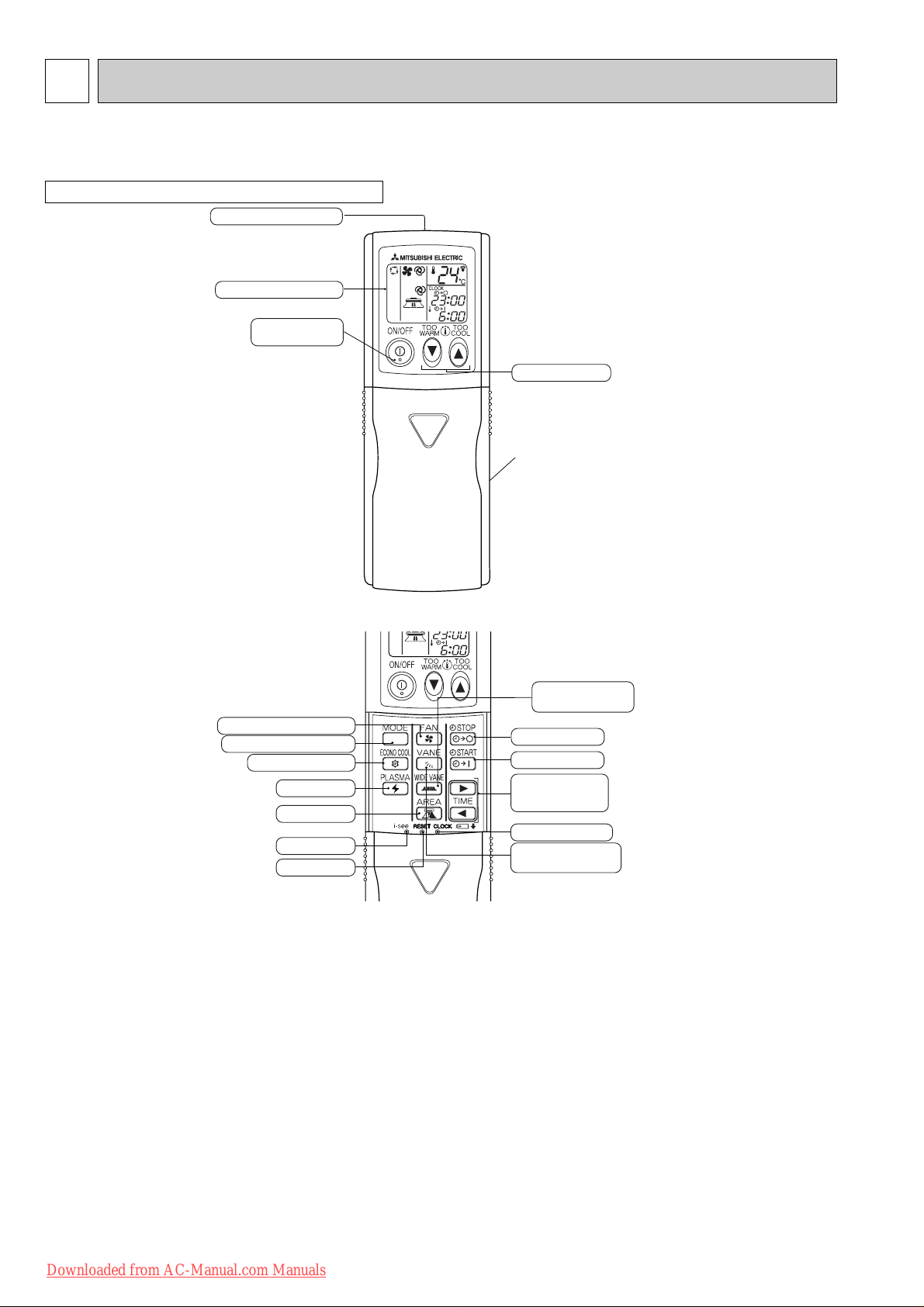
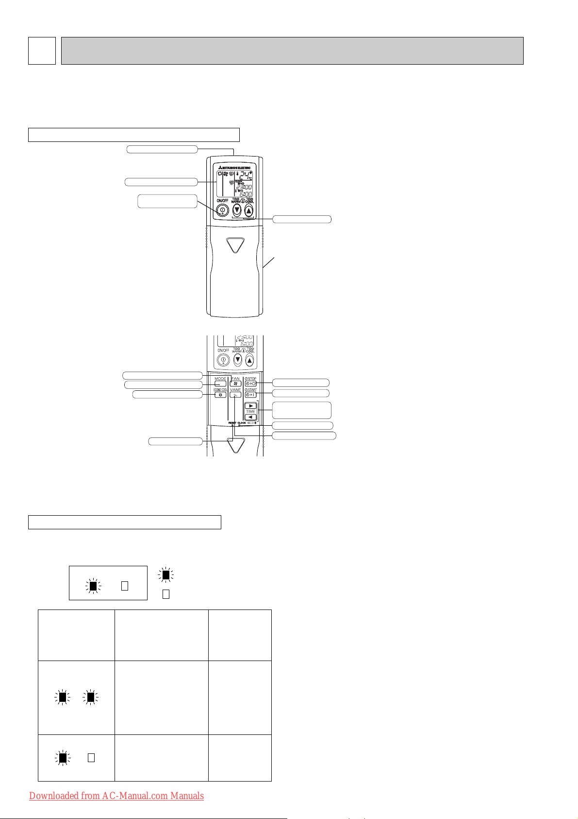
1
ON-TIMER button
CLOCK SET button
TIME SET buttons
FORWARD button
BACKWARD button
VANE CONTROL button
(Horizontal vane button)
OFF-TIMER button
i-see button
(This diagram shows an overall view.)
PLASMA button
AREA button
RESET button
WIDE VANE button
(Vertical vane button)
Signal transmitting section
Operation display section
Temperature buttons
OPERATE/STOP
(ON/OFF) button
FAN SPEED CONTROL button
OPERATION SELECT button
ECONO COOL button
(This diagram shows an overall view.)
Indication of
remote controller
model
MSZ-FA MICROPROCESSOR CONTROL
MSZ-FA25VA MUZ-FA25VA
MSZ-FA35VA MUZ-FA35VA
WIRELESS REMOTE CONTROLLER
Once the operation mode is set, the same operation mode can be repeated by simply turning OPERATE/STOP
(ON/OFF) button ON.
Indoor unit receives the signal with a beep tone.
When the system turns off, 3-minute time delay will operate to protect system from overload and compressor will not
restart for 3 minutes.
Downloaded from AC-Manual.com Manuals
4
Page 5
1-1. COOL ( ) OPERATION
(1) Press OPERATE/STOP(ON/OFF) button.
POWER lamp of the indoor unit turns on with a beep tone.
(2) Select COOL mode with OPERATION SELECT button.
(3) Press TEMPERATURE buttons (TOO WARM or TOO COOL button)to select the desired temperature.
The setting range is 16 ~ 31°C
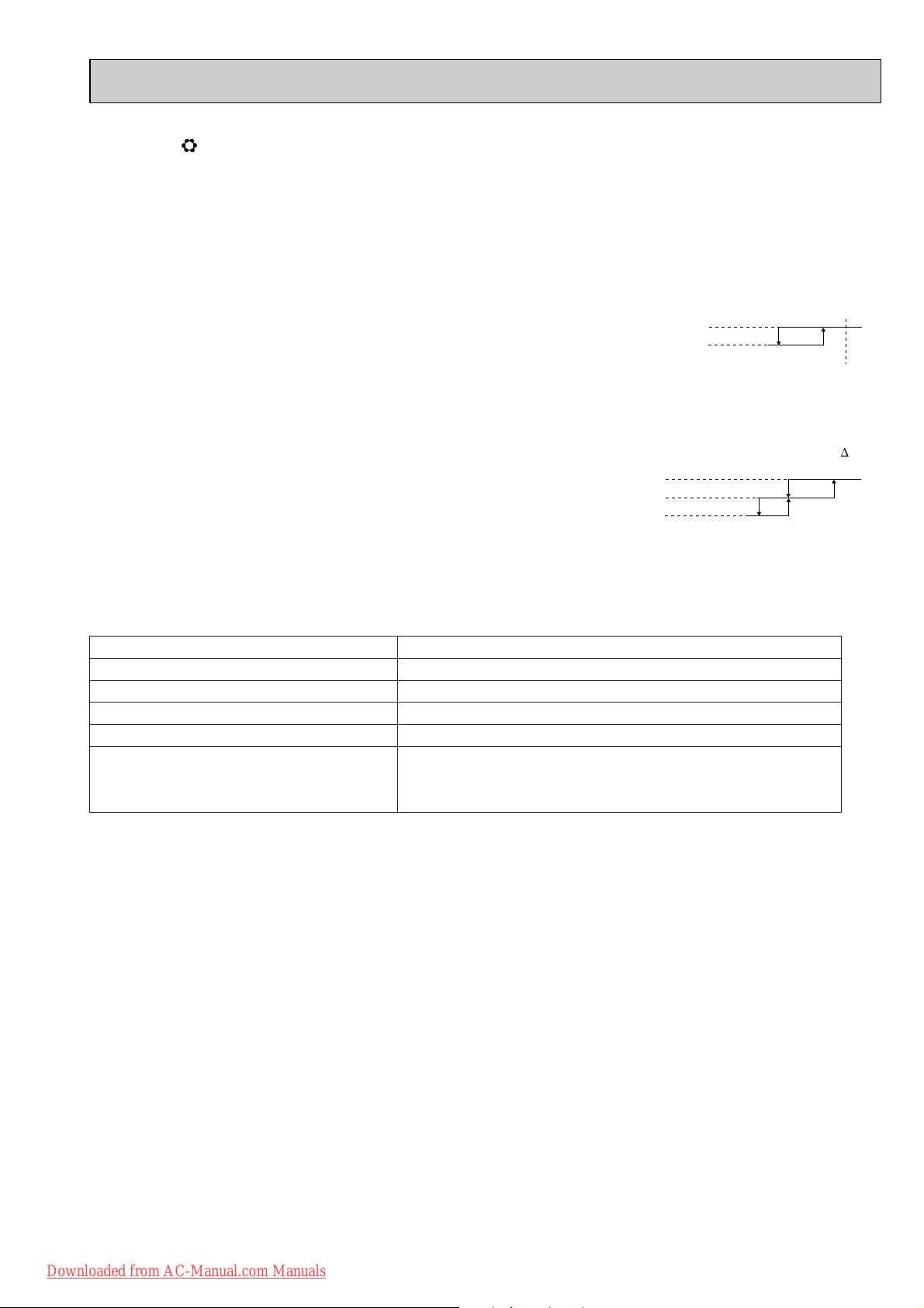
Difference between room
1. Thermostat control
Thermostat is ON or OFF by difference between room temperature and set temperature
Initial temperature difference Thermostat
Room temperature minus set temperature : -1.0 : or more··············································ON
Room temperature minus set temperature : less than -1.0 :············································OFF
2. Indoor fan speed control
Indoor fan operates continuously at the set speed by FAN SPEED CONTROLbutton
regardless of the thermostat’s OFF-ON.
In AUTO the fan speed is as follows.
Room temperature minus set temperature : 1.7
Room temperature minus set temperature : Between 1 and 1.7 :
Initial temperature difference
Fan speed
: or more ········································High
··································
Med.
Room temperature minus set temperature : less than 1 : ········································Low
3. Coil frost prevention
Temperature control
When indoor coil thermistor detects following temperature for 90 seconds, operational frequency
of compressor is controlled according to the following table.
temperature and set temperature during operation.
Difference between room
temperature and set tempera-
ture during operation ( T)
Set temperature
-1.0 :
1 :
-0.7 :
3 :
1.7 :
Temperature of indoor coil thermistor
10°C or more
Operation frequency
Normal (variable)
8°C to 10°C Raise 6 Hz
6°C to 8°C
3°C to 6°C
Fixed
Lower 3Hz
Lower 6Hz
3°C or less
when temperature of indoor coil thermistor continues 3°C or less
Compressor is turned OFF for 5 minutes
for 5 minutes or more.
The indoor fan maintains the actual speed of the moment.
4. Low outside temperature operation
If the outside temperature falls to 18°C or less during operation in COOL mode, the unit enters the low outside temperature
operation mode.
<Operation>
(1) If the unit enters the low outside temperature operation mode, the outside fan rotation speed gets slow down.
(2) Even when the unit is in the "thermostat-off" status under the low outside temperature operation mode, the outside fan
rotation does not stop.
(3) In this mode to detect the exact outside temperature the compressor turns OFF with the outdoor fan ON for 3 minutes
once 1 hour; if the outside temperature rises over 18°C, the unit goes back to the normal COOL mode, and if the outside
temperature is still 18°C or less, the unit stays in the low outside temperature operation mode.
(4) Dew drop prevention
When the ambient temperature thermistor RT65 reads -12: or less, as coil frost or dew drop from indoor unit may
occur, the compressor turns OFF with the outdoor fan ON for prevention of them.
WOther protections work as well as in the normal COOL mode.
Downloaded from AC-Manual.com Manuals
5
Page 6
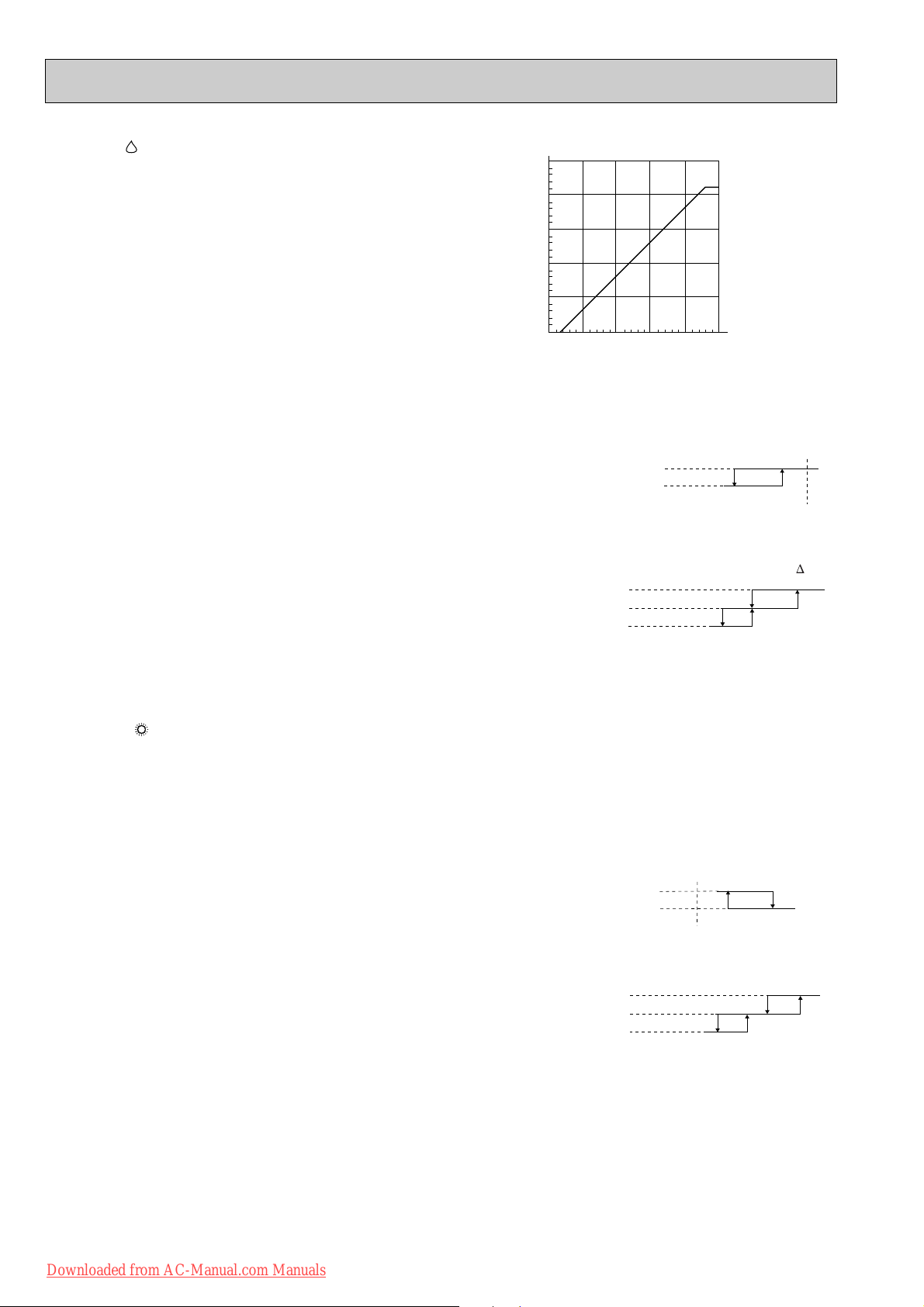
1-2. DRY ( ) OPERATION
35
30
25
20
15
10
:
10 15 20 25 30 35
Set temperature
Initial room temperature
Set temperature and
initial room temperature in dry mode
:
(1) Press OPERATE/STOP(ON/OFF) button.
POWER lamp of the indoor unit turns on with a beep tone.
(2) Select DRY mode with OPERATION SELECT button.
(3) The microprocessor reads the room temperature and determines
the set temperature. Set temperature is as shown on the right
chart.
The system for dry operation uses the same refrigerant circuit as the cooling circuit.
The compressor and the indoor fan are controlled by the room temperature.
By such controls, indoor flow amounts will be reduced in order to lower humidity without much room temperature decrease.
Difference between room
1. Thermostat control
Thermostat is ON or OFF by difference between room temperature and set temperature.
Initial temperature difference Thermostat
temperature and set temperature during operation
Set temperature
Room temperature minus set temperature : -1.0 : or more················································ON
Room temperature minus set temperature : less than -1.0 :··············································OFF
2. Indoor fan speed control
-1.0 :
Indoor fan operates at the set speed by FAN SPEED CONTROLbutton.
When thermostat OFF (compressor OFF) fan speed becomes Very Low.
In AUTO the fan speed is as follows.
Initial temperature difference
Fan speed
Difference between room
temperature and set temperature during operation ( T)
Room temperature minus set temperature : 1.7 : or more ········································High
Room temperature minus set temperature : Between 1 and 1.7 :
··································
Room temperature minus set temperature : less than 1 : ········································Low
Med.
1 :
3. Coil frost prevention
Coil frost prevention is as same as COOL mode. (1-1.3.)
The indoor fan maintains the actual speed of the moment.
4. Low outside temperature operation
Low outside temperature operation is as same as COOL mode. (1-1.4.)
1-3. HEAT ( ) OPERATION
(1) Press OPERATE/STOP(ON/OFF) button.
POWER lamp of the indoor unit turns on with a beep tone.
(2) Select HEAT mode with OPERATION SELECT button.
(3) Press TEMPERATURE buttons (TOO WARM or TOO COOL button) to select the desired temperature.
The setting range is 16 ~ 31°C.
1. Thermostat control
Thermostat is ON or OFF by difference between room temperature and set temperature.
Initial temperature difference Thermostat
Room temperature minus set temperature : less than 2.0 :···············································ON
Room temperature minus set temperature : 2.0 : or more·················································OFF
2. Indoor fan speed control
(1) Indoor fan operates at the set speed by FAN SPEED CONTROLbutton.
In Auto the fan speed is as follows.
Initial temperature difference
Set temperature minus room temperature: 2 :or more
Set temperature minus room temperature:
Between 0.2 and 2 : ·································
Set temperature minus room temperature: less than 0.2
··················································High
:··············································
(2) Cold air prevention control
1 When the compressor is not operating,
(1) if the temperature of room temperature thermistor RT11 is less than 19°C, the fan stops.
(2) if the temperature of room temperature thermistor RT11 is 19°C or more and
(1) if the temperature of RT12 is less than 0°C, the fan stops.
(2) if the temperature of RT12 is 0°C or more, the fan operates at Very Low.
2 When the compressor is operating,
(1) if the temperature of RT12 is 40°C or more, the fan operates at set speed.
(2) if the temperature of RT12 is less than 40°C and
(1) if heating operation starts after defrosting, the fan stops.
(2) if the temperature of room temperature thermistor RT11 is 19°C or less, the fan stops.
NOTE : When 3 minutes have passed since the compressor started operation, this control is released regardless of the
Downloaded from AC-Manual.com Manuals
(3) if the temperature of room temperature thermistor RT11 is more than 19°C, the fan operates at Very Low.
temperature of RT11 and RT12.
Fan speed
Med.
Low
6
Difference between room
temperature and set temperature during operation
Set temperature
1.7 :
Difference between room
temperature and set temperature during operation
0.2 :
1.7 :
1.7 :
-0.7 :
2.0 :
2 :
2.5 :
4 :
Page 7
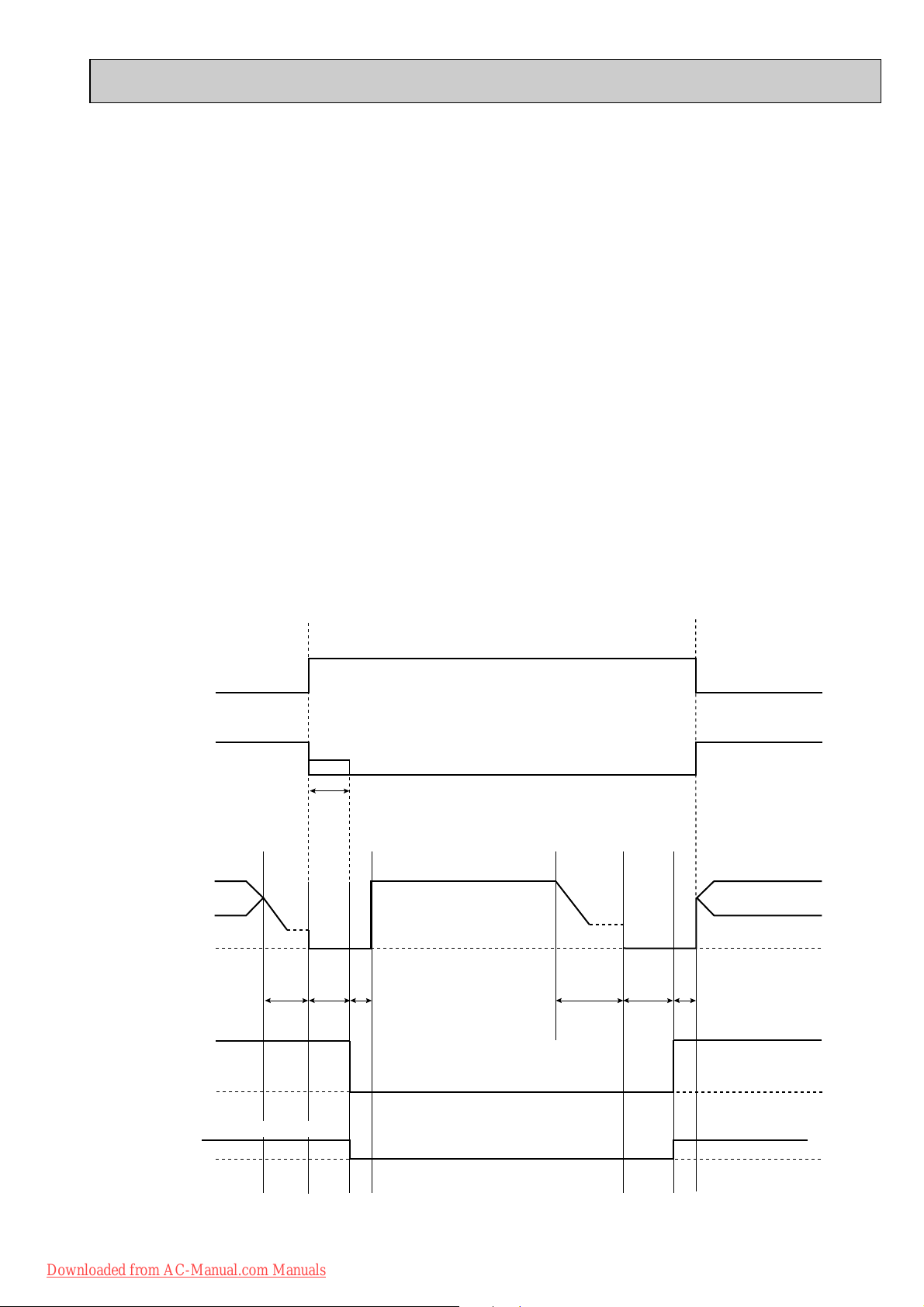
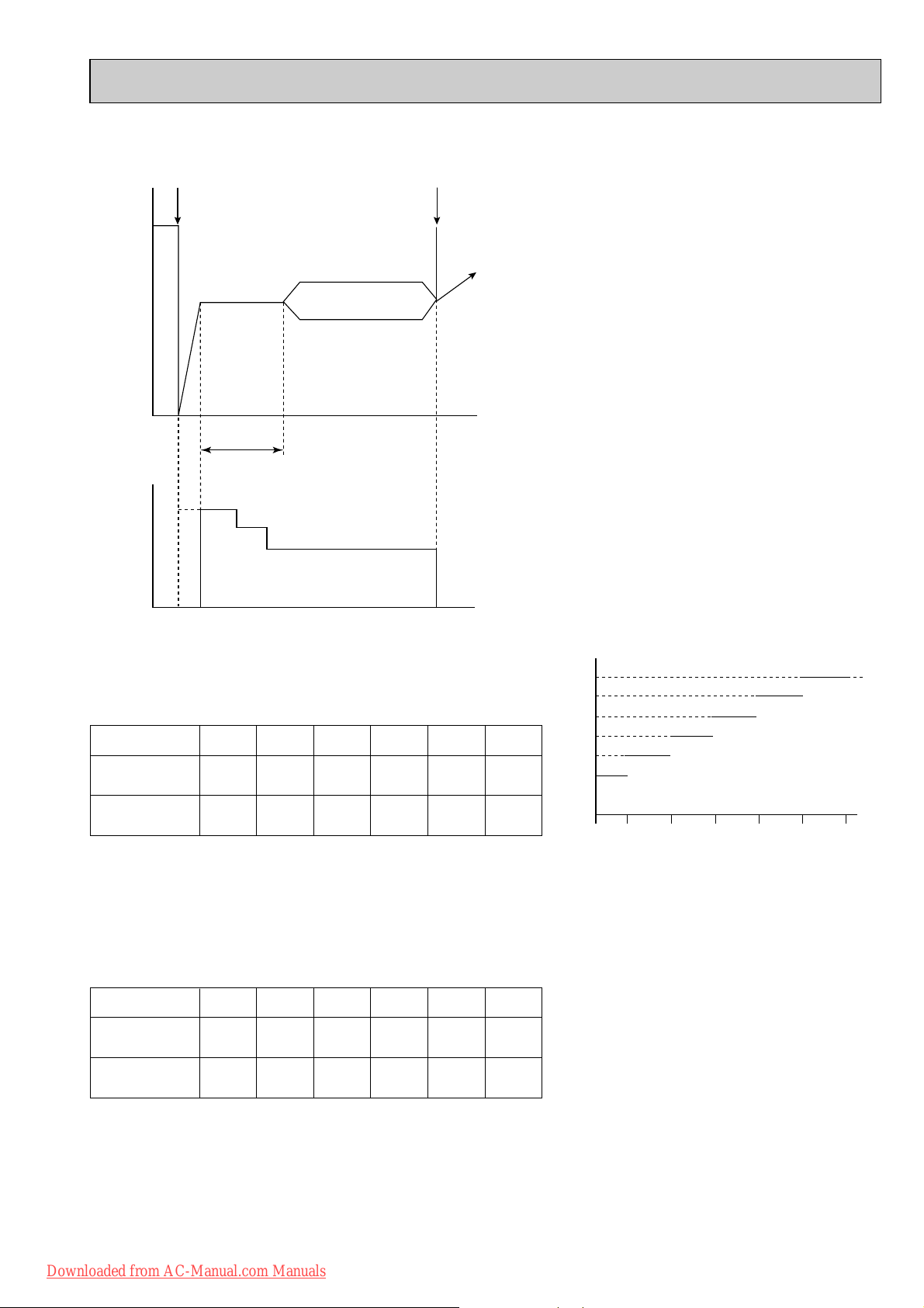
set position
set speed
set position
set speed
Indoor fan
Compressor normal
Outdoor fan
R.V. coil
(21S4)
OFF (COOL)
OFF
Maximum frequency
horizontal
Horizontal vane
Very Low (temperature of indoor coil thermistor > 18:)
30
seconds
30
seconds
30
seconds
40
seconds
5 seconds 5 seconds
40
seconds
OFF
OFF
OFF
ON (HEAT)
ON ON
ON (HEAT)
3. High pressure protection
In HEAT operation the indoor coil thermistor detects the temperature of the indoor heat exchanger. The compressor operational frequency is controlled to prevent the condensing pressure from increasing excessively.
4. Overload starting
When the room temperature thermistor RT11 reads 18°C or more, the compressor runs with its maximum frequency regulated for 10 minutes after the start-up.
5. Defrosting
(1) Starting conditions of defrosting
When the following conditions a) ~ c) are satisfied, the defrosting starts.
a) The defrost thermistor reads -3°C or less.
b) The cumulative operation time of the compressor has reached any of the set valuesw (30, 35, 40, 45, 55, 65, 75, 85,
95, 105, 115, 125, 150 minutes).
c) More than 5 minutes have passed since the start-up of the compressor.
w Set value of compressor operation time(hereinafter referred to as defrost interval)
This is decided by the temperature of defrost thermistor and ambient temperature thermistor, the previous defrosting
time. For example, the first defrost interval is 40 minutes long, and the second is 45 minutes long. The third and sub-
sequent intervals are set to be longer, and less frequent, depending on defrosting time.
The third and subsequent defrost intervals follow any of the three patterns …5 or 10 to 20 minutes longer, the same,
or 5 or 10 to 20 minutes shorter compared with the previous defrost interval … with the longest 150 minutes and the
shortest 30 minutes.
(2) Releasing conditions of defrosting
Defrosting is released when any of the following conditions is satisfied:
a) The defrost thermistor continues to read 5°C or more (MUZ-FA25VA) / 10°C or more (MUZ-FA35VA) for 30 seconds.
b) Defrosting time has exceeded 10 minutes.
c) Any other mode than HEAT mode is set during defrosting.
Time chart of defrosting in HEAT mode (reverse type)
<indoor unit>
<outdoor unit>
Downloaded from AC-Manual.com Manuals
7
Page 8
1-4. AUTO CHANGE OVER ··· AUTO MODE OPERATION
High
Med.
Low
Super High
Super High
time
Rotational frequency
COOL
Fan speed
Up
Down
Up
Down
Mode
HEAT
Compressor frequency
MUZ-FA25 MUZ-FA35
<Relation between compressor frequency and fan speed.>
43Hz
33Hz
43Hz
33Hz
54Hz
41Hz
54Hz
41Hz
Up
Down
Fan speed
High
Low
Compressor frequencyMin. Max.
Once desired temperature is set, unit operation is switched automatically between COOL and HEAT operation.
1. Mode selection
(1) Initial mode
At first indoor unit operates only indoor fan with outdoor unit OFF for 3 minutes to detect present room temperature.
Following the conditions below, operation mode is selected.
1 If the room temperature thermistor RT11 reads more than set temperature, COOL mode is selected.
2 If the room temperature thermistor RT11 reads set temperature or less, HEAT mode is selected.
(2) Mode change
In case of the following conditions the operation mode is changed.
1 COOL mode changes to HEAT mode when 15 minutes have passed with the room temperature 2 degrees below the
set temperature.
2 HEAT mode changes to COOL mode when 15 minutes have passed with the room temperature 2 degrees above the
set temperature.
In the other cases than the above conditions, the present operation mode is continued.
NOTE1: Mode selection is performed when multi standby (refer to NOTE2) is released and the unit starts operation with
ON-timer.
NOTE2: If two or more indoor units are operating in multi system, there might be a case that the indoor unit, which is
operating in AUTO ( ), cannot change over the other operating mode (COOL HEAT) and becomes a
state of standby.
(3) Indoor fan control/ Vane control
As the indoor fan speed and the horizontal vane position depend on the selected operation mode, when the operation
mode changes over, they change to the exclusive ones.
1-5. INDOOR FAN MOTOR CONTROL
(1) Rotational frequency feedback control
The indoor fan motor is equipped with a rotational frequency sensor, and outputs signal to the microprocessor to feedback
the rotational frequency. Comparing the current rotational frequency with the target rotational frequency (Super High, High,
Med., Low), the microprocessor adjusts fan motor electric current to make the current rotational frequency close to the
target rotational frequency. With this control, when the fan speed is switched, the rotational frequency changes smoothly.
(2) Fan motor lock-up protection
When the rotational frequency feedback signal has not output for 12 seconds, (or when the microprocessor cannot
detect the signal for 12 seconds) energizing to the fan motor is stopped. Then the microprocessor retries detection 3
times every 30 seconds. If the microprocessor still cannot detect the signal, the fan motor is regarded locked-up. When
the fan motor lock-up, POWER lamp flashes on and off to show the fan motor abnormality.
1-6. OUTDOOR FAN MOTOR CONTROL
Fan speed is switched according to the compressor frequency.
Downloaded from AC-Manual.com Manuals
8
Page 9
Horizontal
position
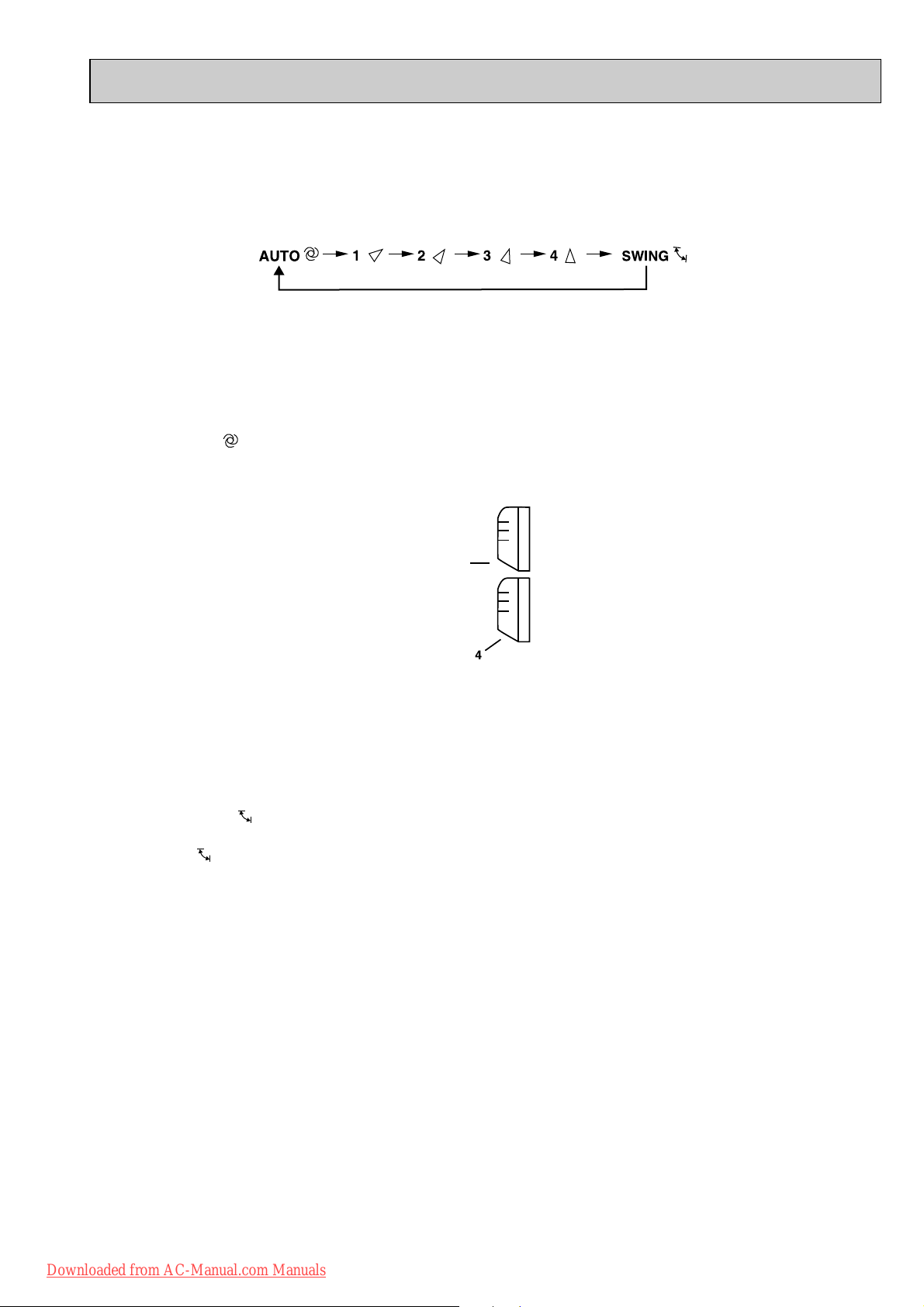
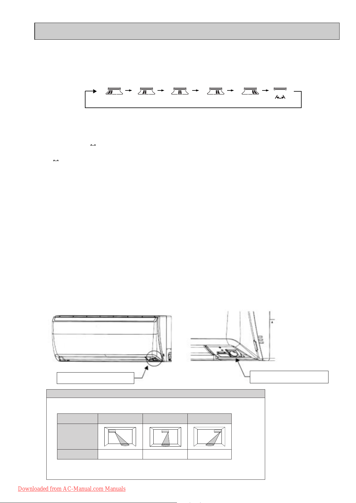
1-7. AUTO VANE OPERATION
1. Horizontal vane
(1) Vane motor drive
These models are equipped with a stepping motor for the horizontal vane. The rotating direction, speed, and angle of
the motor are controlled by pulse signals (approximate 12V) transmitted from indoor microprocessor.
(2) The horizontal vane angle and mode change as follows by pressing VANE CONTROL button.
(3) Positioning
The vane presses the vane stopper once to confirm the standard position and then moves to the set angle.
Confirming of standard position is performed in case of follows.
(a) When the operation starts or finishes (including timer operation).
(b) When the test run starts.
(c) When multi-standby starts or finishes.
(4) VANE AUTO ( ) mode
In VANE AUTO mode, the microprocessor automatically determines the vane angle and operation to make the optimum
room-temperature distribution.
(1) In COOL and DRY operation
(2) In HEAT operation
(5) STOP (operation OFF) and ON-TIMER standby
When the following cases occur, the horizontal vane returns to the closed position.
(a) When OPERATE/STOP (ON/OFF) button is pressed (POWER OFF).
(b) When the operation is stopped by the emergency operation.
(c) When ON-TIMER is ON standby.
(6) Dew prevention
During COOL or DRY operation with the vane angle at Angle 2 ~ 4 when the compressor cumulative operation time
exceeds 1 hour, the vane angle automatically changes to Angle 1 for dew prevention.
(7) SWING MODE ( )
By selecting SWING mode with VANE CONTROL button, the horizontal vane swings vertically. The remote controller
displays “”. SWING mode is cancelled when VANE CONTROL button is pressed once again.
(8) Cold air prevention in HEAT operation.
When any of the following conditions occurs in HEAT operation, the vane angle changes to Horizontal position automatically to prevent cold air blowing on users.
① Compressor is not operating.
➁ Defrosting is performed.
➂ Indoor coil thermistor RT12 reads 24: or below.
➃ Indoor coil thermistor RT12 temperature is raising from 24°C or below, but it does not exceed 39:.
⑤ For about 3 minutes after compressor starts.
Vane angle is fixed to Horizontal position.
Vane angle is fixed to Angle 4.
NOTE : When 2 or more indoor units are operated with multi outdoor unit, even if any indoor unit turns thermostat off,
this control doesn’t work in the indoor unit.
Downloaded from AC-Manual.com Manuals
9
Page 10
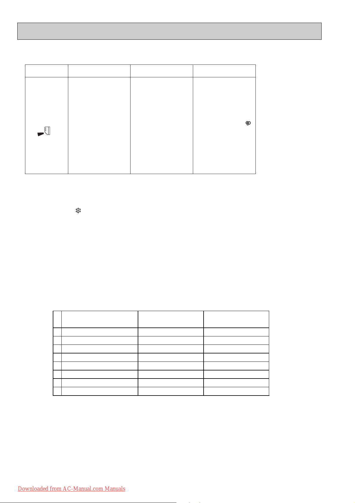
The air conditioner starts heating operation approx. 3 minutes
after the vane has moved to the
horizontal position.
• Sometimes the area
around your feet may not
war m. To warn the area
around the feet, set the
horizontal vane to
(AUTO) or the downwardblowing position.
• When VANE CONTROL
button is pressed again,
the vane returns to the
previously-set position
and the air conditioner
starts the heating operation
in approx. 3minutes.
To change the air
flow direction
When to use this function?
Use this function if you don’t
want the air from the indoor
unit to blow directly onto your
body.
• Depending on the shape of
the room,the air may blow
directly onto your body.
• Press VANE CONTROL
button again to return the
vane to the previously-set
position.
The air conditioner starts the
cooling or drying operation
approx. 3 minutes after the
vane has moved to the horizontal position.
•
Pressing and holding
VANE CONTROL
button for 2 seconds
or more causes
the horizontal vane
to reverse and
move to horizontal
position.
COOL/DRY
HEAT
NOTE:
• If you make the air flow not to blow directly onto your body by pressing VANE CONTROL button,
the compressor stops for 3 minutes even during the operation of the air conditioner.
• The air conditioner operates with decreased air flow until the compressor turns on again.
(9) To change the air flow direction not to blow directly onto your body.
Horizontal
position
When VANE CONTROL
button is pressed again,
the vane returns to the
previously-set position
and the air conditioner
starts the cooling or
drying operation in
approx. 3minutes.
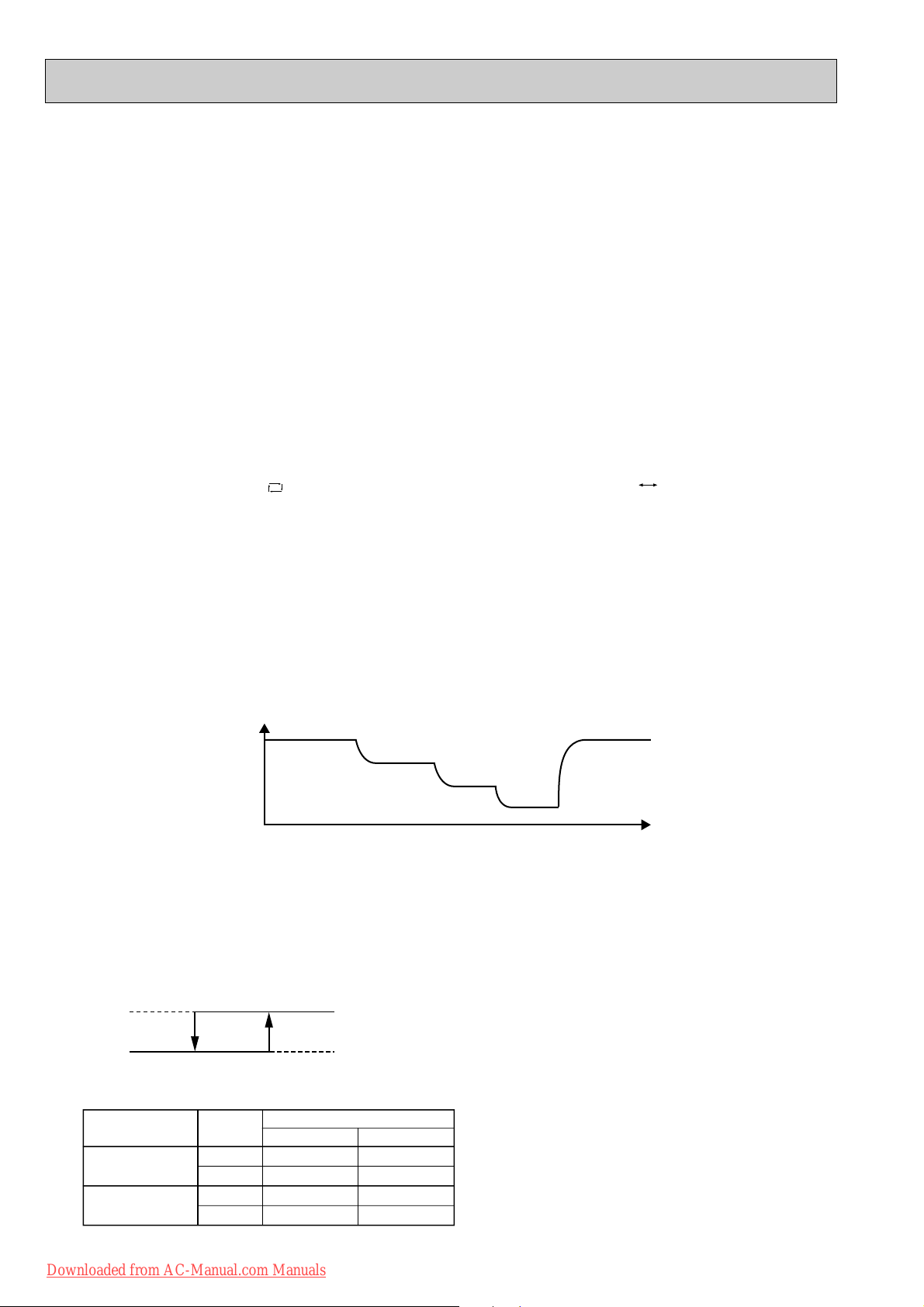
(10) ECONO COOL ( ) operation (ECONOmical operation)
When ECONO COOL button is pressed in COOL mode, set temperature is automatically set 2°C higher than that in
COOL mode.
Also the horizontal vane swings in various cycle according to the temperature of indoor heat exchanger(RT12).
SWING operation makes you feel cooler than set temperature. So, even though the set temperature is higher than that
in COOL mode, the air conditioner can keep comfort. As a result, energy can be saved.
ECONO COOL operation is cancelled when ECONO COOL button is pressed once again or VANE CONTROL
button is pressed or change to other operation mode.
<SWING operation>
In swing operation of ECONO COOL operation mode, the initial air flow direction is adjusted to “Horizontal”.
According to the temperature of indoor coil thermistor RT12 at starting of this operation, next downward blow time is
decided. Then when the downward blow has been finished, next horizontal blow time is decided.
For initial 10 minutes the swing operation is performed in table G~H for quick cooling.
Also, after 10 minutes when the difference of set temperature and room temperature is more than 2:, the swing operation is performed in table D~H for more cooling.
The air conditioner repeats the swing operation in various cycle as follows.
Temperature of indoor
coil thermistor RT12
A
B
C
D
E
F
G
H
15°C or less
15°C to 17°C
17°C to 18°C
18°C to 20°C
20°C to 21°C
21°C to 22°C
22°C to 24°C
more than 24°C
Downward blow time
(second)
2
5
8
11
14
17
20
23
Horizontal blow time
(second)
23
20
17
14
11
8
5
2
Downloaded from AC-Manual.com Manuals
10
Page 11
2. Vertical vane
(1) Vane motor drive
These models are equipped with a stepping motor for the vertical vane. The rotating direction, speed, and angle of the
motor are controlled by pulse signals (approximate 12V) transmitted from microprocessor.
(2) The vertical vane angle and mode change as follows by pressing WIDE VANE button.
1
2 3
4 5
(SWING)
(3) Positioning
The vane is once pressed to the vane stopper to confirm the standard position and then set to the desired angle.
Confirming of standard position is performed in case of follows.
(a) When OPERATE/STOP(ON/OFF) button is pressed (POWER ON).
(b) When SWING is started.
(4) SWING MODE ( )
By selecting SWING mode with WIDE VANE button, the vertical vane swings horizontally. The remote controller displays
“ ”. Swing mode is cancelled when WIDE MODE button is pressed once again.
1-8. i-see CONTROL OPERATION
The sensors constantly measure the room and floor/wall temperatures to automatically adjust to the set temperature
by estimating the temperature actually perceived by a person inside the room (“sensory temperature”).
Advantages
· The air inside the room is conditioned quickly to a comfortable condition.
· The room will not become too cold or hot even when the air conditioner is kept on for a long period.
· The air conditioner will not overcool or overheat, which means you can save on electricity.
i-see control operation is activated when i-see button is pressed with a thin stick in manual COOL or manual HEAT mode.
NOTE :
i-see control operation is activated when the remote controller is first used following replacement of the batteries or
resetting of the remote controller.
i-see control operation is cancelled when i-see button is pressed with a thin stick once again.
NOTE :
If the conditioner is turned OFF without cancelling i-see control operation, i-see control operation is activated the next
time the air conditioner is turned ON.
i-see Sensor
i-see Sensor, which is installed on the right side of the air outlet of the indoor unit, is moved with the stepping motor and it
detects the floor/ wall temperature.
i-see Sensor is installed here.
i-see Sensor
When AREA setting is not activated, the sensing range of i-see Sensor differs depending on the installation
·
location of the air conditioner.
Installation
position
Image of sensing
range
Direction of sensor
Refer to the description on service manual OB371 (8-4. Remote controller) for slide switch settinng.
Installed at left Installed at center Installed at right
Right Center Left
· Install the front panel correctly after being removed for maintenance or service so that the
floor/wall temperatures can be measured correctly.
Downloaded from AC-Manual.com Manuals
Enlarged view of i-see Sensor
11
Page 12

1-9. AREA ( ) SETTING
(1) Press OPERATE / STOP (ON/ OFF)button to start the air conditioner.
(2) Press i-see button. (NOTE 1)
(3) Press AREA button.
Each time the button is pressed, the area is changed in sequence:
NOTE1: AREA setting is only available during i-see control operation.
NOTE2: If AREA setting is canceled, the vertical vane returns to the previously set position before AREA setting.
NOTE3: The horizontal air flow direction (WIDE VANE button), including horizontal SWING, can not be set during AREA setting.
(AUTO) (LEFT) (RIGHT) Cancel
The indoor unit delivers warm air detecting the cold area in the room.
· If AREA setting is set to AUTO in heating operation, the indoor unit automatically delivers warm air to the area
where the floor/wall temperature is the lowest in the room.
· If AREA setting is set to AUTO in cooling operation, the indoor unit automatically delivers cool air to the area
where the floor/wall temperature is the highest in the room.
Ex.) In heating operation
Moving of horizontal air flow direction
Indoor unit
display
NOTE
· The horizontal air flow direction changes if i-see Sensor detects approx. 3; temperature difference.
· In AUTO of AREA setting, both right and left lamps are lighted when the room is evenly air-conditioned.
Indication of AREA setting
Day
Night
Warm area Cold area
Lighted
Not lighted
i-see Sensor moves intermittenly, measuring the floor and wall temperature.
Downloaded from AC-Manual.com Manuals
12
Page 13
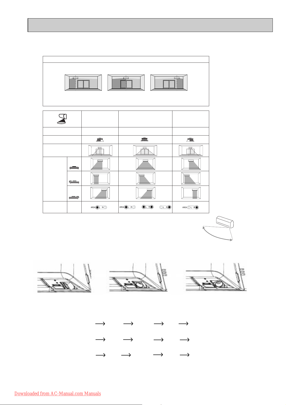
(4) AREA setting is cancelled when the "cancel" is sellected by pressing AREA button, or when WIDE VANE
button is pressed.
Indoor unit installation location and air-conditioning area
Installed at left Installed at center Installed at right
LEFT RIGHT LEFT RIGHT LEFT RIGHT
· Be sure to set the slide switch inside the remote controller to an appropriate position in accordance with the installed
position of the indoor unit. If the switch is not set correctly, the air conditioner may not function properly.
(Refer to Service manual OB371 8-4.)
To air-condition mainly
the left area of the room
Remote controller button
Remote controller display
i-see Sensor operation
Control range
of horizontal air
flow direction.
The vertical air
flow direction
conforms to the
setting on the
remote controller.
(The horizontal
air flow direction
is controlled in
this range.)
Indoor unit
display
NOTE: If the AREA setting is activated (AUTO), i-see Sensor moves in a range of 150 degrees detecting
floor/wall temperature of 3 area (left, right, center). Therefore, the detected temperatures
may be different from the temperatures measured on commercial thermometers
depending on the condition or temperature distribution on the floor and/or wall.
Installed
at center
Installed
at left
Installed
at right
AREA
Press AREA button
to select LEFT.
T o air-condition the entire room
The horizontal air flow direction and indoor unit display are switched according to the room temperature (floor/wall).
Press AREA button to select AUTO.
or
or
Operation and operating range
i-see sensor moves 30 degrees from the center in both right and left side.
To air-condition mainly
the right area of the room
Press AREA button
to select RIGHT.
Approx. 150 degrees
i-see Sensor turning to the left
i-see Sensor turning to the center
i-see Sensor turning to the right
i-see Sensor operates as follows in accordance with AREAsetting made with the remote controller.
“AUTO” in AREAsetting; first turning to the LEFT for adjusting the position then.....
CENTER RIGHT CENTER LEFT CENTER......
(The sensor turns to the right, left and center.)
“RIGHT” in AREAsetting; first turning to the LEFT for adjusting the position then....
CENTER RIGHT CENTER RIGHT CENTER......
(The sensor turns to the right and center.)
“LEFT” in AREAsetting; first turning to the LEFT for adjusting the position then....
CENTER LEFT CENTER LEFT CENTER......
(The sensor turns to the left and center.)
The sensor finishes turning to one area to another for 3 seconds and it operates one area for 5 seconds.
13
Downloaded from AC-Manual.com Manuals
Page 14
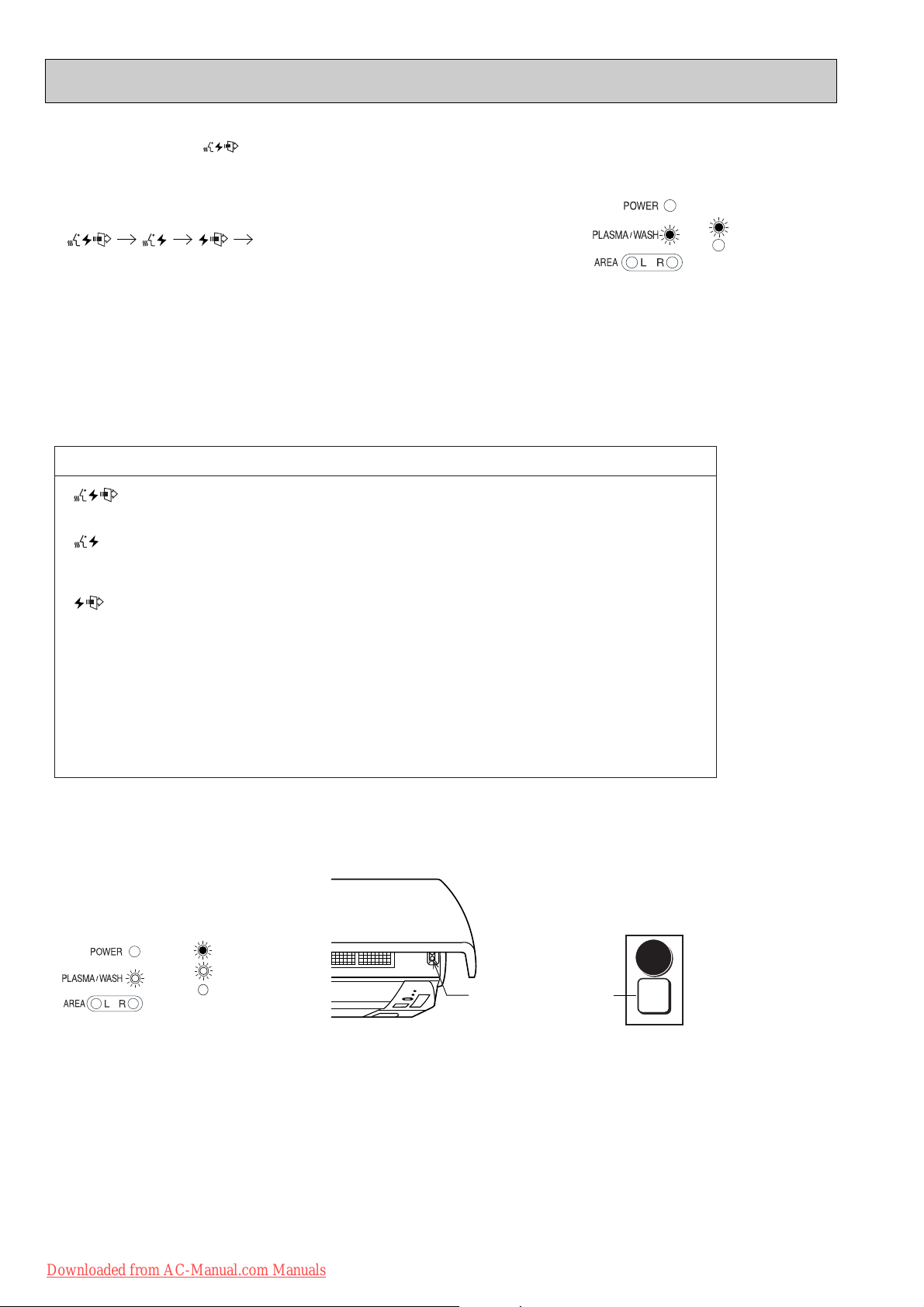
PLASMA/WASH lamp
Blinking
Not lighted
Lighted
WASH reset switch
WASH
reset
E.O.
SW
Each time this b utton is pressed, the oper ation mode of PLASMA is changed in
sequence:
Cancel (The sign of PLASMA oper ation disappears .)
PLASMA/WASH lamp tur ns on in the displa y section of the indoor unit and
PLASMA DEODORIZING and/or PLASMA AIR PURIFYING unit is energyz ed.
Adjust the air flow to your desired speed.
(1) Press OPERATE/STOP (ON/OFF) button to start the air conditioner.
(2) Press PLASMA button to set PLASMA DUO operation.
(3) PLASMA operation is cancelled when the "cancel" is selected by pressing PLASMA button.
Once PLASMA operation is selected, PLASMA operation will be performed every time
the air conditioner is turned on until the "Cancel" is selected with PLASMA button.
1-10. PLASMA DUO ( ) OPERATION
● Never touch the PLASMA DEODORIZING/AIR PURIFYING filter units during the operation of the air
conditioner. Although the filter units are safety-conscious design, touching the units could be the cause
of trouble as they discharge high voltage electricity.
PLASMA/WASH lamp
Not lighted
Lighted
Description of PLASMA DUO operation:
< function>
Both PLASMA DEODORIZING and PLASMA AIR PURIFYING operation work.
<
function>
PLASMA DEODORIZING operation cleans the air inside the room by adsorbing and decomposing
the particles of odor-releasing substances and gases such as formaldehyde.
<
function>
PLASMA AIR PURIFYING operation cleans the air inside the room by absorbing the particles of cigarette
smoke or allergens such as pollens and house dust.
NOTE1: Carbon monoxide released from cigarettes cannot be removed by PLASMA operation.
Open the windows to let the outside air in from time to time.
NOTE2: During PLASMA operation, you may smell ozone that is generated in small quantities
from PLASMA DEODORIZING/AIR PURIFYING filter units. This is not a malfunction.
NOTE3: You may hear a small "hissing" sound during PLASMA operation. This is the sound of plasma
discharge, and not a malfunction.
<Cleaning>
When PLASMA/WASH lamp is blinking, please clean PLASMA DEODORIZING/AIR PURIFYING filter units.
After cleaning of PLASMA DEODORIZING/AIR PURIFYING filter units, press WASH reset switch.
A short “beep” is heard and the blinks of PLASMA/WASH lamp will be cancelled.
Downloaded from AC-Manual.com Manuals
14
Page 15
START
STOP
START
STOP
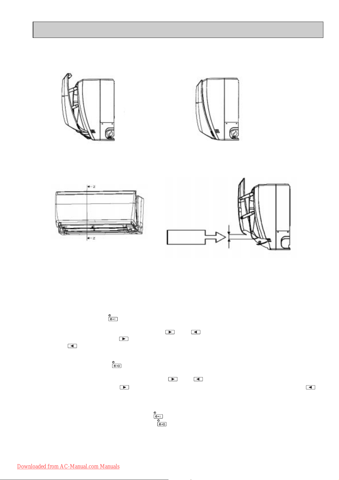
1-11. AUTO FRONT PANEL
When the unit starts operating, the front panel opens automatically to draw in air.
When the unit stops operating, the front panel closes automatically.
Open
Closed
Operation and operating range of the auto front panel
The front panel fully opens 10 mm or more upper than the level line of the top end of the nozzle assembly.
It takes about 13 seconds to open the front panel completely.
10 mm or more
Z-Z Side view
1-12. TIMER OPERATION
1. How to set the timer
(1) Press OPERATE/STOP (ON/OFF) button to start the air conditioner.
(2) Check that the current time is set correctly.
NOTE : Timer operation will not work without setting the current time. Initially “AM0:00” blinks at the current time display of
TIME MONITOR, so set the current time correctly with CLOCK SET button.
ON timer setting
(1) Press ON-TIMER button( ) to set ON timer.
Each time the button is pressed, ON timer mode alternates between ON and OFF.
(2) Set the time of the timer using TIME SET buttons ( and ).
Each time FORWARD button( ) is pressed, the set time increases by 10 minutes; each time BACKWARD
button ( ) is pressed, the set time decreases by 10 minutes.
OFF timer setting
(1) Press OFF-TIMER button ( ) to set OFF timer.
Each time the button is pressed, OFF timer mode alternates between ON and OFF.
(2) Set the time of the timer using TIME SET buttons ( and ).
Each time FORWARD button ( ) is pressed, the set time increases by 10 minutes; each time BACKWARD ( )
button is pressed, the set time decreases by 10 minutes.
2. Cancel
TIMER setting can be cancelled with ON/OFF TIMER buttons.
To cancel ON timer, press ON-TIMER button ( ).
To cancel OFF timer, press OFF-TIMER button( ).
TIMER is cancelled and the display of set time disappears.
Downloaded from AC-Manual.com Manuals
15
Page 16
EMERGENCY OPERATION switch
WASH
reset
E.O.
SW
Operation mode COOL HEAT
Set temperature
24:
24:
Fan speed Medium Medium
Horizontal vane Auto Auto
Vertical vane Straight Straight
The operation mode is indicated by the Operation Indicator lamp on the indoor unit as following figure.
Operation Indicator lamp
NOTE:
This is the indication of EMERGENCY OPERATION
mode. AREA setting is not available during EMERGENCY OPERATION.
Press again <Heat>
Press once <Cool>
Lighted
Not lighted
Press once again <Stop>
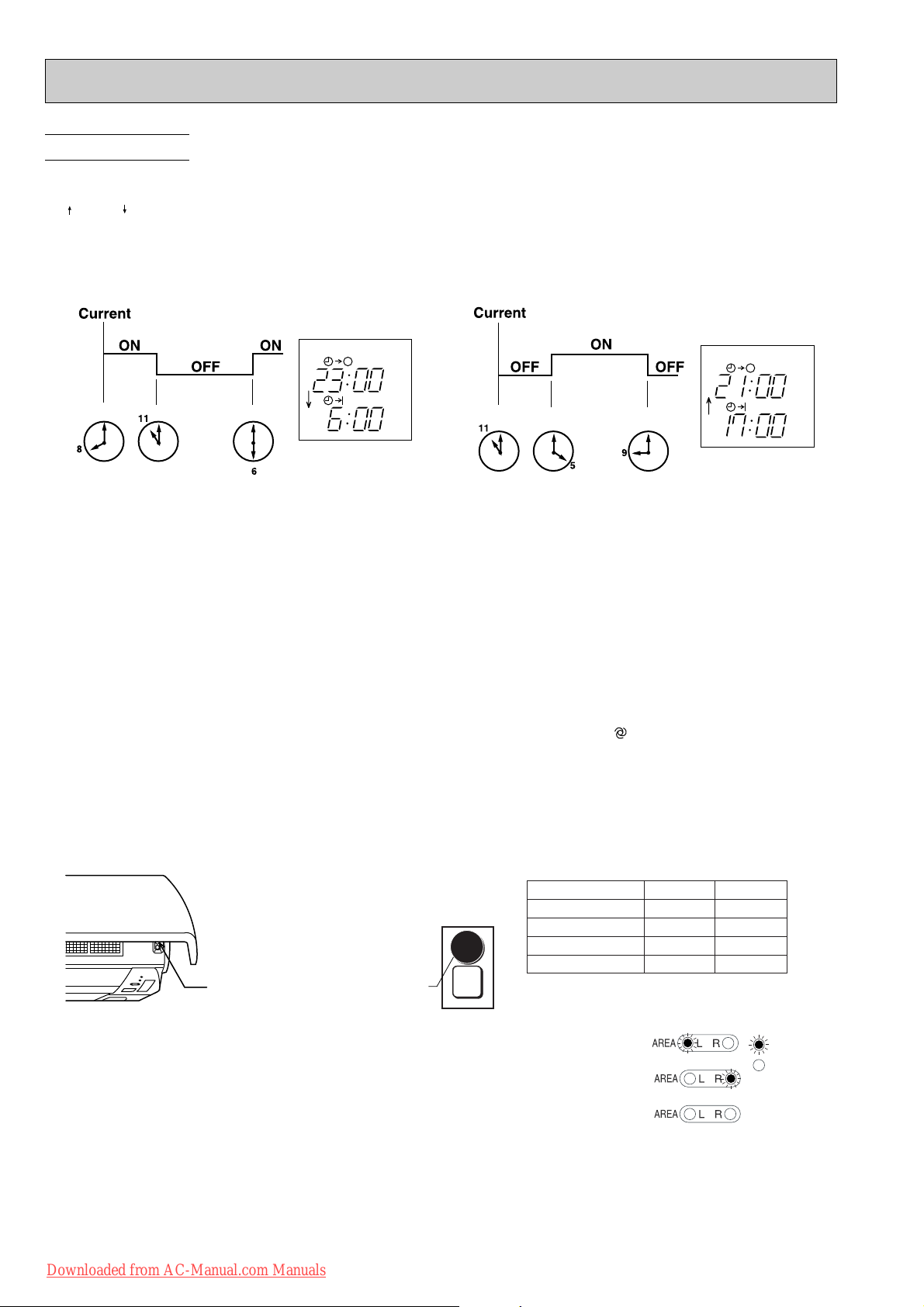
PROGRAM TIMER
• The OFF timer and ON timer can be used in combination. The timer of the set time that is reached first will operate first.
• “ ” and “ ” display shows the order of the OFF timer and the ON timer operation.
(Example 1) The current time is 8:00 PM.
The unit turns off at 11:00 PM, and on at 6:00 AM.
(Example 2) The current time is 11:00 AM.
The unit turns on at 5:00 PM, and off at 9:00 PM.
NOTE : If the main power is turned off or a power failure occurs while AUTO START/STOP timer is active, the timer setting is
cancelled. As these models are equipped with an auto restart function, the air conditioner starts operating with timer
cancelled when power is restored.
1-13. EMERGENCY / TEST OPERATION
In case of test run operation or emergency operation, use EMERGENCY OPERATION switch on the front of the indoor
unit. Emergency operation is available when the remote controller is missing, has failed or the batteries of the remote
controller run down. The unit will start and AREA lamp will light.
The first 30 minutes of operation is the test run operation. This operation is for servicing. The Indoor fan speed runs at
High speed and the system is in continuous operation (The thermostat in ON).
After 30 minutes of test run operation the system shifts to EMERGENCY COOL / HEAT MODE with a set temperature of
24°C. The fan speed shifts to Med..
The coil frost prevention works even in emergency operation, and defrosting too.
In the test run or emergency operation, the horizontal vane operates in VANE AUTO ( ) mode.
Emergency operation continues until EMERGENCY OPERATION switch is pressed once or twice or the unit receives any
signal from the remote controller. In case of latter normal operation will start.
NOTE1 : Do not press EMERGENCY OPERATION switch during normal operation.
NOTE2 : 3 seconds after EMERGENCY OPERATION switch is pressed, the front panel starts moving forward
automatically.
16
Downloaded from AC-Manual.com Manuals
Page 17
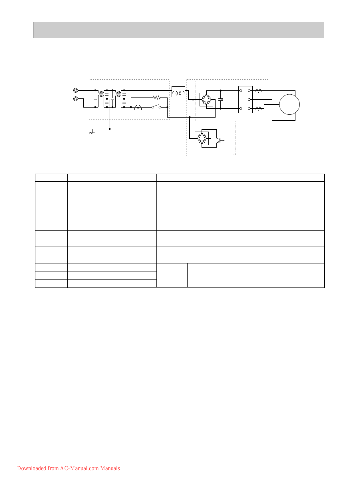
1-14. INVERTER SYSTEM CONTROL
POWER P.C. BOARD
Power
supply
INVERTER P.C. BOARD
R64A R64B
CT
TR821
DB65
X64
L62 L63
C63A
C63B
C63C
DB61
L61
P
W
V
U
N
CT761
CT781
IPM
U
W
MC
V
+
Booster chopper circucuit
SYMBOL
IPM
C63A/C63B/C63C
CT761/CT781
CT
DB61
R64A, R64B
X64
DB65
TR821
L61
NAME
INTELLIGENT POWER MODULE
SMOOTHING CAPACITOR
CURRENT TRANSFORMER
CURRENT TRANSFORMER
DIODE MODULE
CURRENT-LIMITING RESISTOR
RELAY
DIODE MODULE
SWITCHING POWER TRANSISTOR
REACTOR
FUNCTION
It supplies three-phase AC power to compressor.
It stabilizes the DC voltage.
It measures the current of the compressor motor.
It measures the value of current which is supplied to the main power
supply circuit.
It converts the AC voltage to DC voltage.
It absorbs the rush current not to run into the main power supply circuit
when the electricity turns ON.
It short-circuits the resistance which restricts rush current during the
normal operation after the compressor startup.
Booster
chopper
circuit
Function of main parts
It improves power factor.
It rectifies AC and controls its voltage.
1-14-2. Outline of main power supply circuit
1. At the start of operation
Main power supply circuit is formed when X64 (Relay) is turned ON at compressor startup.
To prevent rush current from running into the circuit when power supply is turned ON,
R64A and R64B (Current-limitting resistor) are placed in sub circuit.
2. At normal operation
1 When AC runs into POWER P.C. board, its external noise is eliminated in the noise filter circuit.
2 After noise is eliminated from AC, it is rectified to DC by DB61 (Diode module).
3 DC voltage, to which AC has been rectified by process 2, is stabilized by C63A, C63B and C63C (Smoothing capacitor)
and supplied to IPM (Intelligent power module).
4 DC voltage, which has been stabilized in process 3, is converted to three-phase AC by IPM and supplied to
compressor.
5 CT761 and CT781 (Current Transformer), which are placed in the power supply circuit to compressor, are used to
measure the value of phase current and locate the polar direction of rotor with algorithm. PWM (Pulse width modulation)
controls impressed voltage and frequency with those information.
1-14-1. Inverter main power supply circuit
Downloaded from AC-Manual.com Manuals
17
Page 18
4. Intelligent power module
IPM consists of the following components
· IGBT (x6) : Converts DC waveform to three-phase AC waveform and outputs it.
· Drive Circuit : Drives transistors.
· Protection circuit : Protects transistors from overcurrent.
Since the above components are all integrated in IPM, IPM has a merit to make the control circuit simplify and miniaturize.
5. Smoothing capacitor
C63A, C63B and C63C stabilize the DC voltage and supply it to IPM.
6. Elimination of electrical noice
Noise filter circuit, which is formed by *CMC COILS capacitors placed on the POWER P.C. board, eliminates electrical
noise of AC power that is supplied to main power supply circuit. And this circuit prevents the electrical noise generated in
the inverter circuit from leaking out.
*CMC COILS; Common mode choke coils
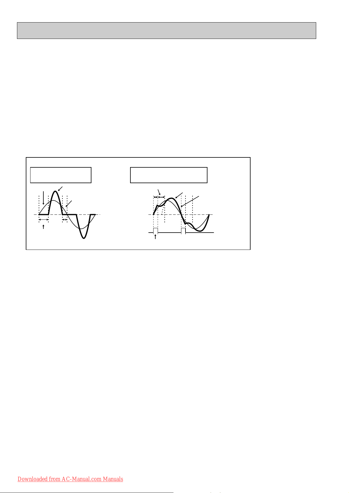
Outline of simple partial switching method
In conventional inverter models, diode module rectifies AC voltage to DC voltage, smoothing capacitor makes its DC waveform
smooth, and IPM converts its DC voltage to imitated AC voltage again in order to drive the compressor motor.
However, it has been difficult to meet IEC harmonic current emission standard by above circuit because harmonic gets
generated in the input current waveform and power factor gets down. The simple partial switching method with PAM, which has
been adopted this time, places and utilizes the booster chopper circuit (L61, DB65 and TR821) before rectifying AC voltage in
the general passive-method converter circuit. As harmonic gets suppressed and the peak of waveform gets lower by adding
booster chopper circuit as mentioned above and by synchronizing the timing of one-time switching with the zero-cross point of
waveform, the input current waveform can be improved and the requirement of IEC harmonic current emission standard can be
satisfied. Since the switching times is just once by synchronizing with the zero cross point, this simple partial switching method
has the feature of lower energy loss compared to active filter method. In addition, output and efficiency is enhanced by
combining with vector-controlled inverter in order to boost the voltage of power supplied to IPM.
Input current waveform without PAM Input current waveform with PAM
Due to the time of no electricity;
· Power factor gets worse.
· Harmonic gets increased.
Input voltage
Release of energy stored in L
Energized time is
extended by optimization
of L inductance.
Peak gets down.
Energized time is short in
case L inductance is small.
No electricity runs into
diode module because the
voltage at both sides of smoothing
capacitor is higher than input voltage.
Compulsory energizing
by switching.
Input current
Owing to the increase of energized time;
· Power factor gets better.
· Harmonic gets suppressed.
3. Purpose of PAM adoption
PAM : Pulse Amplitude Modulation
PAM has been adopted for the efficiency improvement and the adaptation to IEC harmonic current emission standard.
Sine wave control
In these air conditioners, compressor equips brushless DC motor which doesn't have Hall element.
In short, the motor is sensorless. However, it's necessary to locate the polar direction of rotor in order to drive brushless DC
motor efficiently. The general detection method of the polar direction for such a DC motor is to locate it from the voltage induced
by unenergized stator.
Therefore, It is necessary to have a certain period of time in which the stator is being unenergized for the rotor position
detection when the voltage of supplied power is impressed.
So the motor has been driven by square wave control (the conventional motor drive system) which energizes the motor only
when the range of electrical angle is within 120_ because it is forced to be unenergized within 30_ at start & end of one heap
in one waveform cycle (180_) when the voltage is impressed.
However, torque pulsation occurs at rotation in this method when the current-carrying phases are switched over to other
phases in sequence. Therefore, sine wave control system is adopted for these air conditioners because it can make the
phase-to-phase current waveform smoother (sine wave) in order to drive the motor more efficiently and smoothly.
Downloaded from AC-Manual.com Manuals
18
Page 19
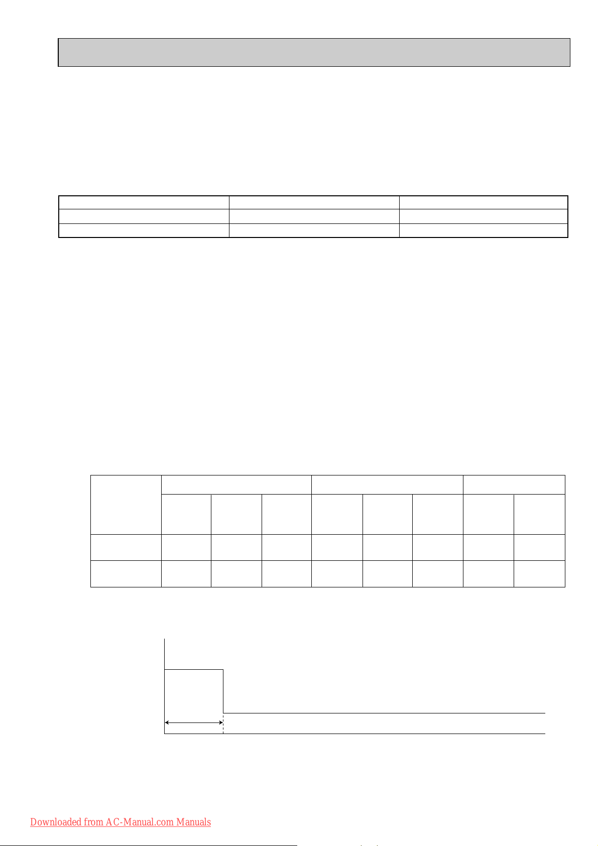
1 hour
Time
Maximum
frequency
Upper limit
frequency
Rated frequency or less
1-15. OPERATIONAL FREQUENCY CONTROL OF OUTDOOR UNIT
Rotor
Rotor Position Signal
Permanent magnet is embedded.
Necessary
DC Motor
Excited by magnetic field of stator
Unnecessary
AC Motor
1-14-3. Characteristics of sine wave control in case of brushless DC motor
● Although ordinary three-phase induction motor requires energy to excite the magnetic field of rotor, brushless DC motor
doesn't need it. So, higher efficiency and torque are provided.
● This control provides the most efficient waveform corresponding to the rotation times of compressor motor.
● The rotation can be set to higher compared to the conventional motor drive system. So, the time in which air conditioner
can be operated with energy saved is longer than conventional models. This can save annual electric consumption.
● Compared to square wave control, the torque pulsation is reduced at rotation so that the motor operates more quietly.
● Since response and efficiency of motor are enhanced in sine wave control, finer adjustment can be provided.
w In brushless DC motor, permanent magnet is embedded in the rotor. Therefore, it doesn't require energy to excite the rotor
like AC motor does. However, it's necessary to control the frequency of three-phase AC current supplied to the stator
according to the polar direction of magnet embedded in the rotor so as to drive the motor efficiently. Controlling three-phase
AC current frequency also means controlling the timing to switch the polarity of stator. Therefore, the polar direction of rotor
needs to be detected.
1-14-4. Control Method of Rotation Times
Sine wave control makes the current transformers conduct real time detection of the value of the current running into the motor,
locates the rotor position from the detected value, and decides if voltage should be impressed and if frequency should be chan ged.
Compared to the conventional control and rotor position detection method, sine wave control can provide finer adjustment of the
voltage of supplied power. The value of the current running into the motor is determined by each motor characteristic.
1. Outline
The operational frequency is as following:
First, the target operational frequency is set based on the difference between the room temperature and the set temperature.
Second, the target operational frequency is regulated by discharge temperature protection, high pressure protection,
electric current protection and overload protection and also by the maximum/minimum frequency.
2. Maximum/minimum frequency in each operation mode.
COOL
Applied
model
MUZ-FA25VA
MUZ-FA35VA
Minimum
frequency
28
28 70
Rated
frequency
57
Maximum
frequency
98
86
Minimum
frequency
45
35
HEAT
Rated
frequency
77 105
73 98 28
Maximum
frequency
Minimum
frequency
DRY
28
w The operation frequency in COOL mode is restricted the upper limit frequency after 1 hour as shown below for
dew prevention.
It is rated frequency or less.
Downloaded from AC-Manual.com Manuals
19
Maximum
frequency
58
57
Page 20

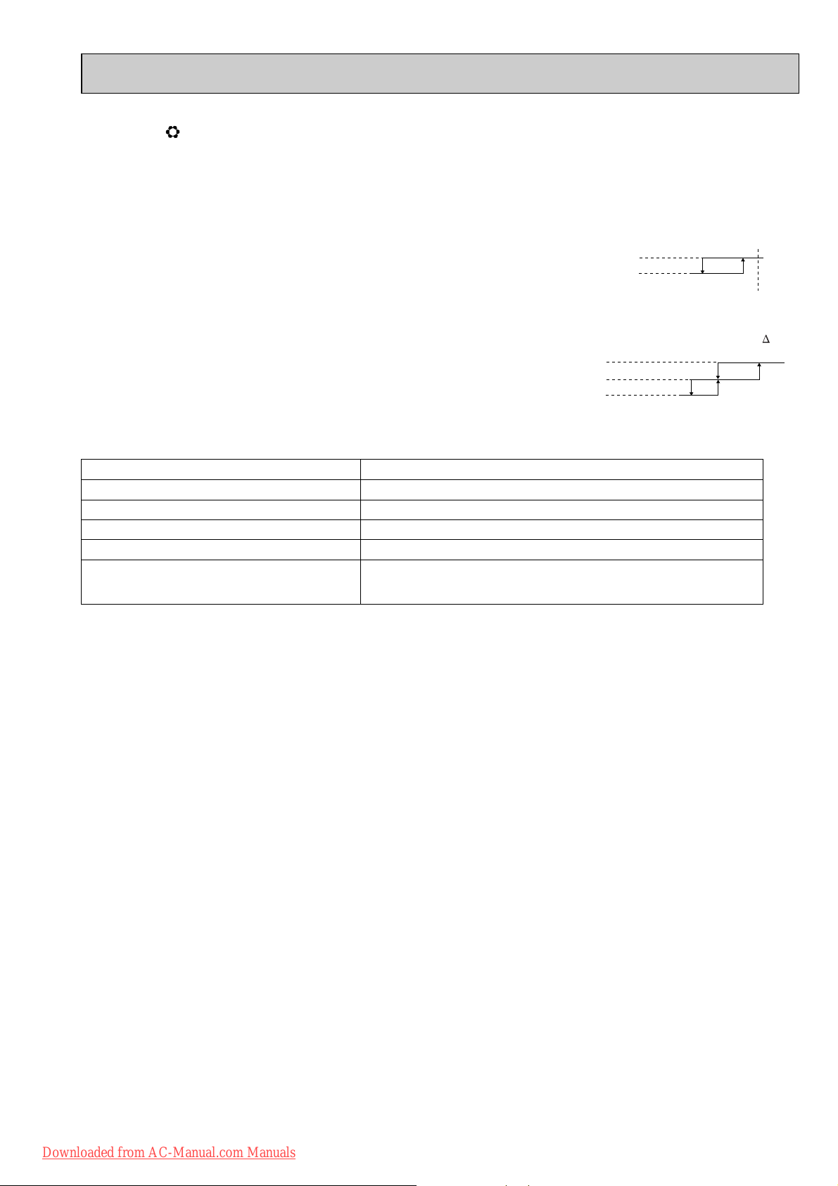
1-16. EXPANSION VALVE CONTROL (LEV CONTROL)
(1) Outline of LEV control
The LEV basic control is comprised of setting LEV opening degree to the standard opening degrees set for each opera-
tional frequency of the compressor. However, when any change in indoor/outdoor temperatures or other factors cause
air conditioning load fluctuation, the LEV control also works to correct LEV opening degree based on discharge temperature (Shell temperature) of the compressor, developing the unit’s performance.
Control range from minimum 33 pulse to maximum 500 pulse.
Actuating speed LEV opens 40 pulse/second and close 90 pulse/second
Opening degree adjustment LEV opening degree is always adjusted in opening direction.
standard
specification
Unit OFF LEV remains at maximum opening degree (reaches maxi-
Remote controller ON LEV is positioned. (first full-closed at zero pulse and then
(When reducing the opening degree, LEV is once overclosed, and then adjusted to the proper degree by opening.
mum opening degree approximate in 15 minutes after compressor stops)
positioned.)
COOL · DRY MODE
During 1 to 5 minutes after compressor starts
HEAT MODE
During 1 to 15 minutes after compressor starts
More than COOL, DRY: 5/ HEAT: 15 minutes have
passed since compressor start-up
general operation
Thermostat OFF LEV is adjusted to exclusive opening degree for thermostat
Thermostat ON
Defrosting in HEAT mode LEV is adjusted to open 500 pulse.
LEV is fixed to standard opening degree according to operational frequency of compressor.
LEV opening degree is corrected to get target discharge
temperature of compressor.
(For discharge temperature lower than target temperature,
LEV is corrected in closing direction.)
(For discharge temperature higher than target temperature,
LEV is corrected in opening direction.)
wIt may take more than 30 minutes to reach target temperature, depending on operating conditions.
OFF.
LEV is controlled in the same way as that after the compressor has started up.
Downloaded from AC-Manual.com Manuals
20
Page 21
(2) Time chart
OFF Time
Time
ON
Operational frequency
of the compressor
Commanded
to open
Standard
opening
degree
Opening degree is
corrected according
to discharge
temperature.
Positioning
Air conditioner ON
Air conditioner OFF
(thermostat off)
LEV opening degree
about 5 minutes <COOL, DRY>
about 15 minutes <HEAT>
06
05
04
03
02
01
LEV opening degree
A(target discharge temperature)
B
C
D
E
F
30 50 70
Operational frequency of the compressor
90 110 130
(Hz)
(3) Control data
(a) Reference value of target discharge temperature
(COOL/HEAT :)
Applied model
MUZ-FA25VA
MUZ-FA35VA
A
47/41B53/48C58/55
50/45
53/52 60/59
In COOL operation, the two indoor coil thermistors (one main and one sub) sense temperature ununiformity (super
heat) at the heat exchanger, and when temperature difference have developed, the indoor coil thermistors adjust
LEV opening degree to get approximate 10 degrees lower temperature than the target temperature in the table
above, thus diminishing super heat.
(b) Reference value of LEV standard opening degree
(COOL/ HEAT pulse)
Applied model
MUZ-FA25VA
MUZ-FA35VA
150/110
130/100
01
02
190/11003240/15004280/17005310/20006340/230
190/130 240/170
Downloaded from AC-Manual.com Manuals
D
63/60
66/68
260/210
E
67/65F67/65
70/76 70/76
260/230
260/230
21
Page 22
2
Approximate
2 :
or more
Difference
between target
temperature
and room
temperature
Approximate
2 :
or less
This shows that the
air conditioner is
operating to reach
the target temperature.
Please wait until the
target temperature is
obtained.
This shows that the
room temperature is
approaching the
target temperature.
Operation stateIndication
Lighted
Not lighted
•The following indication applies regardless of shape of the indicator.
Operation Indicator
MSZ-GA MICROPROCESSOR CONTROL
MSZ-GA22VA
MSZ-GA25VA MUZ-GA25VA
MSZ-GA35VA MUZ-GA35VA
WIRELESS REMOTE CONTROLLER
Signal transmitting section
Operation display section
OPERATE/STOP
(ON/OFF) button
(This diagram shows an overall view.)
Temperature buttons
Indication of
remote controller
model is on back
FAN SPEED CONTROL button
OPERATION SELECT button
ECONO COOL button
RESET button
OFF-TIMER button
ON-TIMER button
TIME SET buttons
FORWARD button
BACKWARD button
CLOCK SET button
VANE CONTROL button
Once the operation mode is set, the same operation mode can be repeated by simply turning OPERATE/STOP
(ON/OFF) button ON.
Indoor unit receives the signal with a beep tone.
When the system turns off, 3-minute time delay will operate to protect system from overload and compressor will not
restart for 3 minutes.
INDOOR UNIT DISPLAY SECTION
Operation Indicator lamp
The operation indicator at the right side of the indoor unit indicates the operation state.
Downloaded from AC-Manual.com Manuals
22
Page 23
2-1. COOL ( ) OPERATION
(1) Press OPERATE/STOP(ON/OFF) button.
OPERATION INDICATOR lamp of the indoor unit turns on with a beep tone.
(2) Select COOL mode with OPERATION SELECT button.
(3) Press TEMPERATURE buttons (TOO WARM or TOO COOL button)to select the desired temperature.
The setting range is 16 ~ 31°C
1. Thermostat control
Thermostat is ON or OFF by difference between room temperature and set temperature
Initial temperature difference Thermostat
Room temperature minus set temperature : -1.0 : or more··············································ON
Room temperature minus set temperature : less than -1.0 :············································OFF
2. Indoor fan speed control
Indoor fan operates continuously at the set speed by FAN SPEED CONTROLbutton
regardless of the thermostat’s OFF-ON.
In AUTO the fan speed is as follows.
Initial temperature difference
Fan speed
Room temperature minus set temperature : 1.7 : or more ········································High
Room temperature minus set temperature : Between 1 and 1.7 :
··································
Med.
Room temperature minus set temperature : less than 1 : ········································Low
3. Coil frost prevention
Temperature control
When indoor coil thermistor detects following temperature for 90 seconds, operational frequency
of compressor is controlled according to the following table.
Temperature of indoor coil thermistor
10°C or more
Operation frequency
Normal (variable)
8°C to 10°C Raise 6Hz
6°C to 8°C
3°C to 6°C
Fixed
Lower 3Hz
Lower 6Hz
3°C or less
Compressor is turned OFF for 5 minutes when temperature of
indoor coil thermistor continues 3°C or less for 5 minutes or more.
The indoor fan maintains the actual speed of the moment.
4. Low outside temperature operation
MSZ-GA25
When the ambient temperature thermistor RT65 reads 17: or less, the operation mode moves to cool operation in low outside temperature from normal cool operation.
Each outdoor actuators (compressor/ fan/ solenoid valve) are operated in the exclusive control, which is different from one
of normal cool operation.
Especially fan motor doesn’t operates continuously to maintain sufficient cooling capacity.
(1) Outdoor fan control
Outdoor unit (compressor) operates with outdoor fan OFF basically.
But any of following conditions is satisfied, the outdoor fan turns ON for about 5 seconds.
a). the defrost thermistor RT61 reads 50: or more.
b). the fin temperature thermistor RT64 reads 60: or more.
(2) Solenoid valve control
In low outside temperature operation solenoid valve coil is energized and solenoid valve is open.
(3) Dew drop prevention
When the ambient temperature thermistor RT65 reads -12: or less, as coil frost or dew drop from indoor unit may
occur, the compressor turns OFF with the outdoor fan ON for prevention of them.
NOTE: This control can be released by cut of the jumper line JG on the outdoor inverter P.C. board.
Be sure to cut it since user accepts that maker can’t be responsible for coil frost or dew drop from indoor unit.
(4) Outside temperature detecting control
In this mode to detect the exact outside temperature the compressor turns OFF with the outdoor fan ON for 3 minutes
once 1 hour.
MSZ-GA35
If the outside temperature falls to 18°C or less during operation in COOL mode, the unit enters the low outside temperature
operation mode.
<Operation>
(1) If the unit enters the low outside temperature operation mode, the outside fan rotation speed gets slow down.
(2) Even when the unit is in the "thermostat-off" status under the low outside temperature operation mode, the outside fan
rotation does not stop.
(3) In this mode to detect the exact outside temperature the compressor turns OFF with the outdoor fan ON for 3 minutes
once 1 hour; if the outside temperature rises over 18°C, the unit goes back to the normal COOL mode, and if the
outside temperature is still 18°C or less, the unit stays in the low outside temperature operation mode.
(4) Dew drop prevention
When the ambient temperature thermistor RT65 reads -12: or less, as coil frost or dew drop from indoor unit may
occur, the compressor turns OFF with the outdoor fan ON for prevention of them.
Difference between room
temperature and set temperature during operation.
Set temperature
-0.7 :
-1.0 :
Difference between room
temperature and set tempera-
ture during operation ( T)
3 :
1.7 :
1 :
WOther protections work as well as in the normal COOL mode.
Downloaded from AC-Manual.com Manuals
23
Page 24

2-2. DRY ( ) OPERATION
35
30
25
20
15
10
:
10 15 20 25 30 35
Set temperature
Initial room temperature
Set temperature and
initial room temperature in dry mode
:
(1) Press OPERATE/STOP(ON/OFF) button.
OPERATION INDICATOR lamp of the indoor unit turns on with a
beep tone.
(2) Select DRY mode with OPERATION SELECT button.
(3) The microprocessor reads the room temperature and determines
the set temperature. Set temperature is as shown on the right
chart.
The system for dry operation uses the same refrigerant circuit as the cooling circuit.
The compressor and the indoor fan are controlled by the room temperature.
By such controls, indoor flow amounts will be reduced in order to lower humidity without much room temperature decrease.
1. Thermostat control
Thermostat is ON or OFF by difference between room temperature and set temperature.
Room temperature minus set temperature : -1.0 : or more··············································ON
Room temperature minus set temperature : less than -1.0 :············································OFF
2. Indoor fan speed control
Indoor fan operates at the set speed by FAN SPEED CONTROLbutton.
When thermostat OFF (compressor OFF) fan speed becomes Very Low.
In AUTO the fan speed is as follows.
Room temperature minus set temperature : 1.7 : or more ········································High
Room temperature minus set temperature : Between 1 and 1.7 :
Room temperature minus set temperature : less than 1 : ········································Low
3. Coil frost prevention
Coil frost prevention is as same as COOL mode. (2-1.3.)
The indoor fan maintains the actual speed of the moment.
4. Low outside temperature operation
Low outside temperature operation is as same as COOL mode. (2-1.4.)
2-3. HEAT ( ) OPERATION
(1) Press OPERATE/STOP(ON/OFF) button.
OPERATION INDICATOR lamp of the indoor unit turns on with a beep tone.
(2) Select HEAT mode with OPERATION SELECT button.
(3) Press TEMPERATURE buttons (TOO WARM or TOO COOL button) to select the desired temperature.
The setting range is 16 ~ 31°C.
1. Thermostat control
Thermostat is ON or OFF by difference between room temperature and set temperature.
Room temperature minus set temperature : less than 2.0 :··············································ON
Room temperature minus set temperature : 2.0 : or more················································OFF
2. Indoor fan speed control
(1) Indoor fan operates at the set speed by FAN SPEED CONTROLbutton.
In Auto the fan speed is as follows.
Set temperature minus room temperature: 2 :or more
Set temperature minus room temperature:
Set temperature minus room temperature: less than 0.2
(2) Cold air prevention control
1 When the compressor is not operating,
(1) if the temperature of room temperature thermistor RT11 is less than 19°C, the fan stops.
Downloaded from AC-Manual.com Manuals
(2) if the temperature of room temperature thermistor RT11 is 19°C or more and
(1) if the temperature of RT12 is less than 0°C, the fan stops.
(2) if the temperature of RT12 is 0°C or more, the fan operates at Very Low.
2 When the compressor is operating,
(1) if the temperature of RT12 is 40°C or more, the fan operates at set speed.
(2) if the temperature of RT12 is less than 40°C and
(1) if heating operation starts after defrosting, the fan stops.
(2) if the temperature of room temperature thermistor RT11 is 19°C or less, the fan stops.
(3) if the temperature of room temperature thermistor RT11 is more than 19°C, the fan operates at Very Low.
NOTE : When 3 minutes have passed since the compressor started operation, this control is released regardless of the
temperature of RT11 and RT12.
Initial temperature difference Thermostat
Initial temperature difference
··································
Fan speed
Med.
Initial temperature difference Thermostat
Initial temperature difference
Fan speed
·················································· High
Between 0.2 and 2 : ·································
:··············································
Med.
Low
24
Difference between room
temperature and set temperature during operation
Set temperature
-1.0 :
-0.7 :
Difference between room
temperature and set temperature during operation ( T)
2.5 :
1.7 :
1 :
Difference between room
temperature and set temperature during operation
Set temperature
2.0 :
1.7 :
Difference between room
temperature and set temperature during operation
2 :
4 :
0.2 :
1.7 :
Page 25

3. High pressure protection
In HEAT operation the indoor coil thermistor detects the temperature of the indoor heat exchanger. The compressor operational frequency is controlled to prevent the condensing pressure from increasing excessively.
4. Overload starting
When the room temperature thermistor RT11 reads 18°C or more, the compressor runs with its maximum frequency regulated for 10 minutes after the start-up.
5. Defrosting
(1) Starting conditions of defrosting
When the following conditions a) ~ c) are satisfied, the defrosting starts.
a) The defrost thermistor reads -3°C or less.
b) The cumulative operation time of the compressor has reached any of the set valuesw (40, 45, 55, 65, 75, 85, 95, 105,
115, 125, 150 minutes).
c) More than 5 minutes have passed since the start-up of the compressor.
w Set value of compressor operation time(hereinafter referred to as defrost interval)
This is decided by the temperature of defrost thermistor and ambient temperature thermistor, the previous defrosting
time. For example, the first defrost interval is 40 minutes long, and the second is 45 minutes long. The third and sub-
sequent intervals are set to be longer, and less frequent, depending on defrosting time.
The third and subsequent defrost intervals follow any of the three patterns …5 or 10 to 20 minutes longer, the same,
or 5 or 10 to 20 minutes shorter compared with the previous defrost interval … with the longest 125 minutes and the
shortest 40 minutes.
(2) Releasing conditions of defrosting
Defrosting is released when any of the following conditions is satisfied:
a) The defrost thermistor continues to read 5°C or more for 30 seconds.
b) Defrosting time has exceeded 10 minutes.
c) Any other mode than HEAT mode is set during defrosting.
Downloaded from AC-Manual.com Manuals
25
Page 26

Time chart of defrosting in HEAT mode (reverse type)
set position
set speed
set position
set speed
Indoor fan
Compressor normal
Outdoor fan
R.V. coil
(21S4)
OFF (COOL)
OFF
Maximum frequency
horizontal
Horizontal vane
Very Low (temperature of indoor coil thermistor > 18:)
30
seconds
30
seconds
30
seconds
40
seconds
5 seconds 5 seconds
40
seconds
OFF
OFF
OFF
ON (HEAT)
ON ON
ON (HEAT)
<indoor unit>
<outdoor unit>
2-4. AUTO CHANGE OVER ··· AUTO MODE OPERATION
Once desired temperature is set, unit operation is switched automatically between COOL and HEAT operation.
1. Mode selection
(1) Initial mode
At first indoor unit operates only indoor fan with outdoor unit OFF for 3 minutes to detect present room temperature.
Following the conditions below, operation mode is selected.
1 If the room temperature thermistor RT11 reads more than set temperature, COOL mode is selected.
2 If the room temperature thermistor RT11 reads set temperature or less, HEAT mode is selected.
(2) Mode change
In case of the following conditions the operation mode is changed.
1 COOL mode changes to HEAT mode when 15 minutes have passed with the room temperature 2 degrees below the
set temperature.
2 HEAT mode changes to COOL mode when 15 minutes have passed with the room temperature 2 degrees above the
set temperature.
In the other cases than the above conditions, the present operation mode is continued.
NOTE1: Mode selection is performed when multi standby (refer to NOTE2) is released and the unit starts operation with
ON-timer.
NOTE2: If two or more indoor units are operating in multi system, there might be a case that the indoor unit, which is
operating in AUTO ( ), cannot change over the other operating mode (COOL HEAT) and becomes a
state of standby.
(3) Indoor fan control/ Vane control
As the indoor fan speed and the horizontal vane position depend on the selected operation mode, when the operation
mode changes over, they change to the exclusive ones.
Downloaded from AC-Manual.com Manuals
26
Page 27

2-5. INDOOR FAN MOTOR CONTROL
COOL
Fan speed
Up
Down
Up
Down
Mode
HEAT
Compressor frequency
MUZ-GA35
<Relation between compressor frequency and fan speed.>
54Hz
41Hz
54Hz
41Hz
Up
Down
Fan speed
High
Low
Compressor frequencyMin. Max.
(1) Rotational frequency feedback control
The indoor fan motor is equipped with a rotational frequency sensor, and outputs signal to the microprocessor to feedback
the rotational frequency. Comparing the current rotational frequency with the target rotational frequency (Super High, High,
Med., Low), the microprocessor adjusts fan motor electric current to make the current rotational frequency close to the
target rotational frequency. With this control, when the fan speed is switched, the rotational frequency changes smoothly.
Rotational frequency
Super High
High
Med.
Low
Super High
time
(2) Fan motor lock-up protection
When the rotational frequency feedback signal has not output for 12 seconds, (or when the microprocessor cannot
detect the signal for 12 seconds) energizing to the fan motor is stopped. Then the microprocessor retries detection 3
times every 30 seconds. If the microprocessor still cannot detect the signal, the fan motor is regarded locked-up. When
the fan motor lock-up, POWER lamp flashes on and off to show the fan motor abnormality.
2-6. OUTDOOR FAN MOTOR CONTROL MUZ-GA35
Fan speed is switched according to the compressor frequency.
2-7. AUTO VANE OPERATION
1. Horizontal vane
(1) Vane motor drive
These models are equipped with a stepping motor for the horizontal vane. The rotating direction, speed, and angle of
the motor are controlled by pulse signals (approximate 12V) transmitted from indoor microprocessor.
(2) The horizontal vane angle and mode changes as follows by pressing VANE CONTROL button.
(3) Positioning
The vane presses the vane stopper once to confirm the standard position and then moves to the set angle.
Confirming of standard position is performed in case of follows.
Downloaded from AC-Manual.com Manuals
(a) When the operation starts or finishes (including timer operation).
(b) When the test run starts.
(c) When multi-standby starts or finishes.
27
Page 28

(4) VANE AUTO ( ) mode
Horizontal
position
The air conditioner starts heating operation approx. 3 minutes
after the vane has moved to the
horizontal position.
• Sometimes the area
around your feet may not
war m. To warn the area
around the feet, set the
horizontal vane to
(AUTO) or the downwardblowing position.
• When VANE CONTROL
button is pressed again,
the vane returns to the
previously-set position
and the air conditioner
starts the heating operation
in approx. 3minutes.
To change the air
flow direction
When to use this function?
Use this function if you don’t
want the air from the indoor
unit to blow directly onto your
body.
• Depending on the shape of
the room,the air may blow
directly onto your body.
• Press VANE CONTROL
button again to return the
vane to the previously-set
position.
The air conditioner starts the
cooling or drying operation
approx. 3 minutes after the
vane has moved to the horizontal position.
•
Pressing and holding
VANE CONTROL
button for 2 seconds
or more causes
the horizontal vane
to reverse and
move to horizontal
position.
COOL/DRY
HEAT
NOTE:
• If you make the air flow not to blow directly onto your body by pressing VANE CONTROL button,
the compressor stops for 3 minutes even during the operation of the air conditioner.
• The air conditioner operates with decreased air flow until the compressor turns on again.
(9) To change the air flow direction not to blow directly onto your body.
Horizontal
position
When VANE CONTROL
button is pressed again,
the vane returns to the
previously-set position
and the air conditioner
starts the cooling or
drying operation in
approx. 3minutes.
In VANE AUTO mode, the microprocessor automatically determines the vane angle and operation to make the optimum
room-temperature distribution.
(1) In COOL and DRY operation
Vane angle is fixed to Horizontal position.
(2) In HEAT operation
Vane angle is fixed to Angle 4.
(5) STOP (operation OFF) and ON-TIMER standby
When the following cases occur, the horizontal vane returns to the closed position.
(a) When OPERATE/STOP (ON/OFF) button is pressed (POWER OFF).
(b) When the operation is stopped by the emergency operation.
(c) When ON-TIMER is ON standby.
(6) Dew prevention
During COOL or DRY operation with the vane angle at Angle 2 ~ 4 when the compressor cumulative operation time
exceeds 1 hour, the vane angle automatically changes to Angle 1 for dew prevention.
(7) SWING MODE ( )
By selecting SWING mode with VANE CONTROL button, the horizontal vane swings vertically. The remote controller
displays “”. SWING mode is cancelled when VANE CONTROL button is pressed once again.
(8) Cold air prevention in HEAT operation.
When any of the following conditions occurs in HEAT operation, the vane angle changes to Horizontal position automatically to prevent cold air blowing on users.
① Compressor is not operating.
➁ Defrosting is performed.
➂ Indoor coil thermistor RT12 reads 24: or below.
➃ Indoor coil thermistor RT12 temperature is raising from 24°C or below, but it does not exceed 39:.
⑤ For about 3 minutes after compressor starts.
NOTE: When 2 or more indoor units are operated with multi outdoor unit, even if any indoor unit turns thermostat off,
this control doesn’t work in the indoor unit.
Downloaded from AC-Manual.com Manuals
28
Page 29

(
START
STOP
START
STOP
10
) ECONO COOL ( ) operation (ECONOmical operation)
When ECONO COOL button is pressed in COOL mode, set temperature is automatically set 2°C higher than that in
COOL mode.
Also the horizontal vane swings in various cycle according to the temperature of indoor heat exchanger(RT12).
SWING operation makes you feel cooler than set temperature. So, even though the set temperature is higher than that
in COOL mode, the air conditioner can keep comfort. As a result, energy can be saved.
ECONO COOL operation is cancelled when ECONO COOL button is pressed once again or VANE CONTROL
button is pressed or change to other operation mode.
<SWING operation>
In swing operation of ECONO COOL operation mode, the initial air flow direction is adjusted to “Horizontal”.
According to the temperature of indoor coil thermistor RT12 at starting of this operation, next downward blow time is
decided. Then when the downward blow has been finished, next horizontal blow time is decided.
For initial 10 minutes the swing operation is performed in table G~H for quick cooling.
Also, after 10 minutes when the difference of set temperature and room temperature is more than 2:, the swing operation is performed in table D~H for more cooling.
The air conditioner repeats the swing operation in various cycle as follows.
Temperature of indoor
coil thermistor RT12
A
B
C
D
E
F
G
H
15°C or less
15°C to 17°C
17°C to 18°C
18°C to 20°C
20°C to 21°C
21°C to 22°C
22°C to 24°C
more than 24°C
Downward blow time
(second)
2
5
8
11
14
17
20
23
Horizontal blow time
(second)
23
20
17
14
11
8
5
2
2-8. TIMER OPERATION
1. How to set the timer
(1) Press OPERATE/STOP (ON/OFF) button to start the air conditioner.
(2) Check that the current time is set correctly.
NOTE : Timer operation will not work without setting the current time. Initially “AM0:00” blinks at the current time display of
TIME MONITOR, so set the current time correctly with CLOCK SET button.
ON timer setting
(1) Press ON-TIMER button( ) to set ON timer.
Each time the button is pressed, ON timer mode alternates between ON and OFF.
(2) Set the time of the timer using TIME SET buttons ( and ).
Each time FORWARD button( ) is pressed, the set time increases by 10 minutes; each time BACKWARD
button ( ) is pressed, the set time decreases by 10 minutes.
OFF timer setting
(1) Press OFF-TIMER button ( ) to set OFF timer.
Each time the button is pressed, OFF timer mode alternates between ON and OFF.
(2) Set the time of the timer using TIME SET buttons ( and ).
Each time FORWARD button ( ) is pressed, the set time increases by 10 minutes; each time BACKWARD ( )
button is pressed, the set time decreases by 10 minutes.
2. Cancel
TIMER setting can be cancelled with ON/OFF TIMER buttons.
To cancel ON timer, press ON-TIMER button ( ).
To cancel OFF timer, press OFF-TIMER button( ).
TIMER is cancelled and the display of set time disappears.
Downloaded from AC-Manual.com Manuals
29
Page 30

EMERGENCY OPERATION switch
E.O.
SW
Operation mode COOL HEAT
Set temperature
24:
24:
Fan speed Medium Medium
Horizontal vane Auto Auto
The operation mode is indicated by the Operation
Indicator lamp on the indoor unit as following
Operation indicator lamp
Press again <Heat>
Press once <Cool>
Press once again <Stop>
Not lighted
Lighted
PROGRAM TIMER
• OFF timer and ON timer can be used in combination. The timer of the set time that is reached first will operate first.
• “ ” and “ ” display shows the order of OFF timer and ON timer operation.
(Example 1) The current time is 8:00 PM.
The unit turns off at 11:00 PM, and on at 6:00 AM.
(Example 2) The current time is 11:00 AM.
The unit turns on at 5:00 PM, and off at 9:00 PM.
NOTE : If the main power is turned off or a power failure occurs while AUTO START/STOP timer is active, the timer setting is
cancelled. As these models are equipped with an auto restart function, the air conditioner starts operating with timer
cancelled when power is restored.
2-9. EMERGENCY/TEST OPERATION
In case of test run operation or emergency operation, use EMERGENCY OPERATION switch on the front of the indoor
unit. Emergency operation is available when the remote controller is missing, has failed or the batteries of the remote
controller run down. The unit will start and OPERATION INDICATOR lamp will light.
The first 30 minutes of operation is the test run operation. This operation is for servicing. The Indoor fan speed runs at
High speed and the system is in continuous operation (The thermostat in ON).
After 30 minutes of test run operation the system shifts to EMERGENCY COOL / HEAT MODE with a set temperature of
24°C. The fan speed shifts to Med..
The coil frost prevention works even in emergency operation, and defrosting too.
In the test run or emergency operation, the horizontal vane operates in VANE AUTO ( ) mode.
Emergency operation continues until EMERGENCY OPERATION switch is pressed once or twice or the unit receives any
signal from the remote controller. In case of latter normal operation will start.
NOTE : Do not press EMERGENCY OPERATION switch during normal operation.
Downloaded from AC-Manual.com Manuals
30
Page 31

2-10. INVERTER SYSTEM CONTROL
POWER P.C. BOARD
Power
supply
INVERTER P.C. BOARD
R64A R64B
CT
TR821
DB65
X64
L62 L63
C63A
C63B
C63C
DB61
L61
P
W
V
U
N
CT761
CT781
IPM
U
W
MC
V
+
Booster chopper circucuit
SYMBOL
IPM
C63A/C63B/C63C
CT761/CT781
CT
DB61
R64A, R64B
X64
DB65
TR821
L61
NAME
INTELLIGENT POWER MODULE
SMOOTHING CAPACITOR
CURRENT TRANSFORMER
CURRENT TRANSFORMER
DIODE MODULE
CURRENT-LIMITING RESISTOR
RELAY
DIODE MODULE
SWITCHING POWER TRANSISTOR
REACTOR
FUNCTION
It supplies three-phase AC power to compressor.
It stabilizes the DC voltage.
It measures the current of the compressor motor.
It measures the value of current which is supplied to the main power
supply circuit.
It converts the AC voltage to DC voltage.
It absorbs the rush current not to run into the main power supply circuit
when the electricity turns ON.
It short-circuits the resistance which restricts rush current during the
normal operation after the compressor startup.
Booster
chopper
circuit
Function of main parts
It improves power factor.
It rectifies AC and controls its voltage.
2-10-2. Outline of main power supply circuit
1. At the start of operation
Main power supply circuit is formed when X64 (Relay) is turned ON at compressor startup.
To prevent rush current from running into the circuit when power supply is turned ON,
R64A and R64B (Current-limitting resistor) are placed in sub circuit.
2. At normal operation
1 When AC runs into POWER P.C. board, its external noise is eliminated in the noise filter circuit.
2 After noise is eliminated from AC, it is rectified to DC by DB61 (Diode module).
3 DC voltage, to which AC has been rectified by process 2, is stabilized by C63A, C63B and C63C (Smoothing capacitor)
and supplied to IPM (Intelligent power module).
4 DC voltage, which has been stabilized in process 3, is converted to three-phase AC by IPM and supplied to
compressor.
5 CT761 and CT781 (Current Transformer), which are placed in the power supply circuit to compressor, are used to
measure the value of phase current and locate the polar direction of rotor with algorithm. PWM (Pulse width modulation)
controls impressed voltage and frequency with those information.
2-10-1. Inverter main power supply circuit
Downloaded from AC-Manual.com Manuals
31
Page 32

4. Intelligent power module
IPM consists of the following components
· IGBT (x6) : Converts DC waveform to three-phase AC waveform and outputs it.
· Drive Circuit : Drives transistors.
· Protection circuit : Protects transistors from overcurrent.
Since the above components are all integrated in IPM, IPM has a merit to make the control circuit simplify and miniaturize.
5. Smoothing capacitor
C63A, C63B and C63C stabilize the DC voltage and supply it to IPM.
6. Elimination of electrical noice
Noise filter circuit, which is formed by *CMC COILS capacitors placed on the POWER P.C. board, eliminates electrical
noise of AC power that is supplied to main power supply circuit. And this circuit prevents the electrical noise generated in
the inverter circuit from leaking out.
*CMC COILS; Common mode choke coils
Outline of simple partial switching method
In conventional inverter models, diode module rectifies AC voltage to DC voltage, smoothing capacitor makes its DC waveform
smooth, and IPM converts its DC voltage to imitated AC voltage again in order to drive the compressor motor.
However, it has been difficult to meet IEC harmonic current emission standard by above circuit because harmonic gets
generated in the input current waveform and power factor gets down. The simple partial switching method with PAM, which has
been adopted this time, places and utilizes the booster chopper circuit (L61, DB65 and TR821) before rectifying AC voltage in
the general passive-method converter circuit. As harmonic gets suppressed and the peak of waveform gets lower by adding
booster chopper circuit as mentioned above and by synchronizing the timing of one-time switching with the zero-cross point of
waveform, the input current waveform can be improved and the requirement of IEC harmonic current emission standard can be
satisfied. Since the switching times is just once by synchronizing with the zero cross point, this simple partial switching method
has the feature of lower energy loss compared to active filter method. In addition, output and efficiency is enhanced by
combining with vector-controlled inverter in order to boost the voltage of power supplied to IPM.
Input current waveform without PAM Input current waveform with PAM
Due to the time of no electricity;
· Power factor gets worse.
· Harmonic gets increased.
Input voltage
Release of energy stored in L
Energized time is
extended by optimization
of L inductance.
Peak gets down.
Energized time is short in
case L inductance is small.
No electricity runs into
diode module because the
voltage at both sides of smoothing
capacitor is higher than input voltage.
Compulsory energizing
by switching.
Input current
Owing to the increase of energized time;
· Power factor gets better.
· Harmonic gets suppressed.
3. Purpose of PAM adoption
PAM : Pulse Amplitude Modulation
PAM has been adopted for the efficiency improvement and the adaptation to IEC harmonic current emission standard.
Sine wave control
In these air conditioners, compressor equips brushless DC motor which doesn't have Hall element.
In short, the motor is sensorless. However, it's necessary to locate the polar direction of rotor in order to drive brushless DC
motor efficiently. The general detection method of the polar direction for such a DC motor is to locate it from the voltage induced
by unenergized stator.
Therefore, It is necessary to have a certain period of time in which the stator is being unenergized for the rotor position
detection when the voltage of supplied power is impressed.
So the motor has been driven by square wave control (the conventional motor drive system) which energizes the motor only
when the range of electrical angle is within 120_ because it is forced to be unenergized within 30_ at start & end of one heap
in one waveform cycle (180_) when the voltage is impressed.
However, torque pulsation occurs at rotation in this method when the current-carrying phases are switched over to other
phases in sequence. Therefore, sine wave control system is adopted for these air conditioners because it can make the
phase-to-phase current waveform smoother (sine wave) in order to drive the motor more efficiently and smoothly.
Downloaded from AC-Manual.com Manuals
32
Page 33

1 hour
Time
Maximum
frequency
Upper limit
frequency
Rated frequency or less
2-11. OPERATIONAL FREQUENCY CONTROL OF OUTDOOR UNIT
Rotor
Rotor Position Signal
Permanent magnet is embedded.
Necessary
DC Motor
Excited by magnetic field of stator
Unnecessary
AC Motor
2-10-3. Characteristics of sine wave control in case of brushless DC motor
● Although ordinary three-phase induction motor requires energy to excite the magnetic field of rotor, brushless DC motor
doesn't need it. So, higher efficiency and torque are provided.
● This control provides the most efficient waveform corresponding to the rotation times of compressor motor.
● The rotation can be set to higher compared to the conventional motor drive system. So, the time in which air conditioner
can be operated with energy saved is longer than conventional models. This can save annual electric consumption.
● Compared to square wave control, the torque pulsation is reduced at rotation so that the motor operates more quietly.
● Since response and efficiency of motor are enhanced in sine wave control, finer adjustment can be provided.
w In brushless DC motor, permanent magnet is embedded in the rotor. Therefore, it doesn't require energy to excite the rotor
like AC motor does. However, it's necessary to control the frequency of three-phase AC current supplied to the stator
according to the polar direction of magnet embedded in the rotor so as to drive the motor efficiently. Controlling three-phase
AC current frequency also means controlling the timing to switch the polarity of stator. Therefore, the polar direction of rotor
needs to be detected.
2-10-4. Control Method of Rotation Times
Sine wave control makes the current transformers conduct real time detection of the value of the current running into the motor,
locates the rotor position from the detected value, and decides if voltage should be impressed and if frequency should be chan ged.
Compared to the conventional control and rotor position detection method, sine wave control can provide finer adjustment of the
voltage of supplied power. The value of the current running into the motor is determined by each motor characteristic.
1. Outline
The operational frequency is as following:
First, the target operational frequency is set based on the difference between the room temperature and the set temperature.
Second, the target operational frequency is regulated by discharge temperature protection, high pressure protection,
electric current protection and overload protection and also by the maximum/minimum frequency.
2. Maximum/minimum frequency in each operation mode.
COOL
Applied
model
MUZ-GA25VA
MUZ-GA35VA
Minimum
frequency
28
28 88
Rated
frequency
65
Maximum
frequency
70
98
Minimum
frequency
48
45
HEAT
Rated
frequency
85 105
96 105 28
Maximum
frequency
Minimum
frequency
DRY
28
w The operation frequency in COOL mode is restricted the upper limit frequency after 1 hour as shown below for
dew prevention.
It is rated frequency or less.
Downloaded from AC-Manual.com Manuals
33
Maximum
frequency
40
58
Page 34

2-12. EXPANSION VALVE CONTROL (LEV CONTROL) MSZ-GA35
(1) Outline of LEV control
The LEV basic control is comprised of setting LEV opening degree to the standard opening degrees set for each opera-
tional frequency of the compressor. However, when any change in indoor/outdoor temperatures or other factors cause
air conditioning load fluctuation, the LEV control also works to correct LEV opening degree based on discharge temperature (Shell temperature) of the compressor, developing the unit’s performance.
Control range from minimum 33 pulse to maximum 500 pulse.
Actuating speed LEV opens 40 pulse/second and close 90 pulse/second
Opening degree adjustment LEV opening degree is always adjusted in opening direction.
standard
specification
Unit OFF LEV remains at maximum opening degree (reaches maxi-
Remote controller ON LEV is positioned. (first full-closed at zero pulse and then
(When reducing the opening degree, LEV is once overclosed, and then adjusted to the proper degree by opening.
mum opening degree approximate in 15 minutes after compressor stops)
positioned.)
COOL · DRY MODE
During 1 to 5 minutes after compressor starts
HEAT MODE
During 1 to 15 minutes after compressor starts
More than COOL, DRY: 5/ HEAT: 15 minutes have
passed since compressor start-up
general operation
Thermostat OFF LEV is adjusted to exclusive opening degree for thermostat
Thermostat ON LEV is controlled in the same way as that after the compres-
Defrosting in HEAT mode LEV is adjusted to open 500 pulse.
LEV is fixed to standard opening degree according to opera-
tional frequency of compressor.
LEV opening degree is corrected to get target discharge
temperature of compressor.
(For discharge temperature lower than target temperature,
LEV is corrected in closing direction.)
(For discharge temperature higher than target temperature,
LEV is corrected in opening direction.)
wIt may take more than 30 minutes to reach target tempera-
ture, depending on operating conditions.
OFF.
sor has started up.
Downloaded from AC-Manual.com Manuals
34
Page 35

(2) Time chart
OFF Time
Time
ON
Operational frequency
of the compressor
Commanded
to open
Standard
opening
degree
Opening degree is
corrected according
to discharge
temperature.
Positioning
Air conditioner ON
Air conditioner OFF
(thermostat off)
LEV opening degree
about 5 minutes <COOL, DRY>
about 15 minutes <HEAT>
06
05
04
03
02
01
LEV opening degree
A(target discharge temperature)
B
C
D
E
F
30 50 70
Operational frequency of the compressor
90 110 130
(Hz)
(3) Control data
(a) Reference value of target discharge temperature
Applied model
MUZ-GA35VA
(COOL/HEAT
47/41
:)
A B C D E F
53/48 58/55
In COOL operation, the two indoor coil thermistors (one main and one sub) sense temperature ununiformity (super
heat) at the heat exchanger, and when temperature difference have developed, the indoor coil thermistors adjust
LEV opening degree to get approximate 10 degrees lower temperature than the target temperature in the table
above, thus diminishing super heat.
(b) Reference value of LEV standard opening degree
(COOL/ HEAT pulse)
Applied model
MUZ-GA35VA
01 02 03 04 05 06
150/110
190/110 240/150
Downloaded from AC-Manual.com Manuals
63/60
280/170
67/65
310/200
67/65
340/230
35
Page 36

MSZ-GA50VA MSZ-GA60VA MUZ-GA50VA MUZ-GA60VA
MSZ-GA71VA MSZ-GA80VA MUZ-GA71VA MUZ-GA80VA
WIRELESS REMOTE CONTROLLER
Signal transmitting section
Operation display section
OPERATE /STOP
(ON /OFF)button
ON/OFF
TOO
WARM
TOO
COOL
TEMPERATURE buttons
Indication of remote controller
model is on back.
WIDE VANE button
(Vertical vane button)
FAN SPEED CONTROL button
OPERATION SELECT button
ECONO COOL button
LONG
LONG button
RESET button
OFF-TIMER button
ON-TIMER button
TIME SET buttons
FORWARD button
BACKWARD button
CLOCK SET button
VANE CONTROL button
(Horizontal vane button)
Once the operation mode is set, the same operation mode can be repeated by simply turning OPERATE/STOP
(ON/OFF) button ON.
Indoor unit receives the signal with a beep tone.
When the system turns off, 3-minute time delay will operate to protect system from overload and compressor will not
restart for 3 minutes.
2-13. COOL ( ) OPERATION
(1) Press OPERATE/STOP(ON/OFF) button.
OPERATION INDICATOR lamp of the indoor unit turns on with a beep tone.
(2) Select COOL mode with OPERATION SELECT button.
(3) Press TEMPERATURE buttons (TOO WARM or TOO COOL button)to select the desired temperature.
The setting range is 16 ~ 31°C
1. Thermostat control
Thermostat is ON or OFF by difference between room temperature and set temperature
Initial temperature difference Thermostat
Room temperature minus set temperature : -1.0 : or more··············································ON
Room temperature minus set temperature : less than -1.0 :············································OFF
Difference between room
temperature and set temperature during operation.
Set temperature
-1.0 :
-0.7 :
Downloaded from AC-Manual.com Manuals
36
Page 37

35
30
25
20
15
10
:
10 15 20 25 30 35
Set temperature
Initial room temperature
Set temperature and
initial room temperature in dry mode
:
2. Indoor fan speed control
Indoor fan operates continuously at the set speed by FAN SPEED CONTROLbutton
regardless of the thermostat’s OFF-ON.
In AUTO the fan speed is as follows.
Initial temperature difference
Fan speed
Room temperature minus set temperature : 1.7 : or more ········································High
Room temperature minus set temperature : Between 1 and 1.7 :
··································
Med.
Room temperature minus set temperature : less than 1 : ········································Low
3. Coil frost prevention
Temperature control
When indoor coil thermistor detects following temperature for 90 seconds, operational frequency
of compressor is controlled according to the following table.
Temperature of indoor coil thermistor
10°C or more
Operation frequency
Normal (variable)
8°C to 10°C Raise 6Hz
6°C to 8°C
3°C to 6°C
Fixed
Lower 3Hz
Difference between room
temperature and set tempera-
ture during operation ( T)
3 :
1.7 :
1 :
3°C or less
Compressor is turned OFF for 5 minutes when temperature of
indoor coil thermistor continues 3°C or less for 5 minutes or more.
The indoor fan maintains the actual speed of the moment.
4. Low outside temperature operation
If the outside temperature falls to 18°C or less during operation in COOL mode, the unit enters the low outside temperature
operation mode.
<Operation>
(1) If the unit enters the low outside temperature operation mode, the outside fan rotation speed gets slow down.
(2) Even when the unit is in the "thermostat-off" status under the low outside temperature operation mode, the outside fan
rotation does not stop.
(3) Outside temperature detecting control
In this mode to detect the exact outside temperature the compressor turns OFF with the outdoor fan ON for 3 minutes
once 1 hour; if the outside temperature rises over 18°C, the unit goes back to the normal COOL mode, and if the outside
temperature is still 18°C or less, the unit stays in the low outside temperature operation mode.
(4) Dew drop prevention
When the ambient temperature thermistor RT65 reads -12: or less, as coil frost or dew drop from indoor unit may
occur, the compressor turns OFF with the outdoor fan ON for prevention of them.
WOther protections work as well as in the normal COOL mode.
2-14. DRY ( ) OPERATION
(1) Press OPERATE/STOP(ON/OFF) button.
OPERATION INDICATOR lamp of the indoor unit turns on with a
beep tone.
(2) Select DRY mode with OPERATION SELECT button.
(3) The microprocessor reads the room temperature and determines
the set temperature. Set temperature is as shown on the right
chart.
Lower 6Hz
The system for dry operation uses the same refrigerant circuit as the cooling circuit.
The compressor and the indoor fan are controlled by the room temperature.
By such controls, indoor flow amounts will be reduced in order to lower humidity without much room temperature decrease.
Downloaded from AC-Manual.com Manuals
37
Page 38

Difference between room
1. Thermostat control
Thermostat is ON or OFF by difference between room temperature and set temperature.
Initial temperature difference Thermostat
temperature and set temperature during operation
Set temperature
Room temperature minus set temperature : -1.0 : or more··············································ON
Room temperature minus set temperature : less than -1.0 :············································OFF
-1.0 :
2. Indoor fan speed control
-0.7 :
Indoor fan operates at the set speed by FAN SPEED CONTROLbutton.
When thermostat OFF (compressor OFF) fan speed becomes Very Low.
3. Coil frost prevention
Coil frost prevention is as same as COOL mode. (2-13.3.)
The indoor fan maintains the actual speed of the moment. However, when coil frost prevention works while the compressor
is not operating it’s speed becomes the set speed.
4. Low outside temperature operation
Low outside temperature operation is as same as COOL mode. (2-13.4.)
2-15. HEAT ( ) OPERATION
(1) Press OPERATE/STOP(ON/OFF) button.
OPERATION INDICATOR lamp of the indoor unit turns on with a beep tone.
(2) Select HEAT mode with OPERATION SELECT button.
(3) Press TEMPERATURE buttons (TOO WARM or TOO COOL button) to select the desired temperature.
The setting range is 16 ~ 31°C.
1. Thermostat control
Thermostat is ON or OFF by difference between room temperature and set temperature.
Initial temperature difference Thermostat
Room temperature minus set temperature : less than 2.0 :··············································ON
Room temperature minus set temperature : 2.0 : or more················································OFF
2. Indoor fan speed control
(1) Indoor fan operates at the set speed by FAN SPEED CONTROLbutton.
In Auto the fan speed is as follows.
Initial temperature difference
Set temperature minus room temperature: 2 :or more
Set temperature minus room temperature:
Between 1 and 2 : ····································
Set temperature minus room temperature: less than 1
·················································· High
:·················································
Fan speed
Med.
Low
(2) Cold air prevention control
1 When the compressor is not operating,
(1) if the temperature of room temperature thermistor RT11 is 15°C or less, or RT12 is less than 18°C,
the fan stops.
(2) if the temperature of room temperature thermistor RT11 is more than 15°C, or RT12 is more than 18°C,
the fan operates at Very Low.
2 When the compressor is operating,
(1) if the temperature of RT12 is 18°C or more, the fan operates at set speed.
(2) if the temperature of RT12 is less than 18°C and
(1) if heating operation starts after defrosting, the fan stops.
(2) if the temperature of room temperature thermistor RT11 is 15°C or less, the fan stops.
(3) if the temperature of room temperature thermistor RT11 is more than 15°C, the fan operates at Very Low.
Difference between room
temperature and set temperature during operation
Set temperature
2.0 :
1.7 :
Difference between room
temperature and set temperature during operation
2 :
1 :
1.7 :
4 :
NOTE : When 3 minutes have passed since the compressor started operation, this control is released regardless of the
temperature of RT11 and RT12.
38
Downloaded from AC-Manual.com Manuals
Page 39

3. High pressure protection
set position
set speed
set position
set speed
Indoor fan
Compressor normal
Outdoor fan
R.V. coil
(21S4)
OFF (COOL)
OFF
Maximum frequency
horizontal
Horizontal vane
Very Low (temperature of indoor coil thermistor > 18:)
30
seconds
30
seconds
30
seconds
40
seconds
5 seconds 5 seconds
40
seconds
OFF
OFF
OFF
ON (HEAT)
ON ON
ON (HEAT)
In HEAT operation the indoor coil thermistor detects the temperature of the indoor heat exchanger. The compressor operational frequency is controlled to prevent the condensing pressure from increasing excessively.
4. Overload starting
When the room temperature thermistor RT11 reads 18°C or more, the compressor runs with its maximum frequency regulated for 10 minutes after the start-up.
5. Defrosting
(1) Starting conditions of defrosting
When the following conditions a) ~ c) are satisfied, the defrosting starts.
a) The defrost thermistor reads -3°C or less.
b) The cumulative operation time of the compressor has reached any of the set valuesw (31, 35, 45, 55, 65, 75, 85, 95,
105, 115, 150 minutes).
c) More than 5 minutes have passed since the start-up of the compressor.
w Set value of compressor operation time(hereinafter referred to as defrost interval)
This is decided by the temperature of defrost thermistor and ambient temperature thermistor, the previous defrosting
time. For example, the first defrost interval is 40 minutes long, and the second is 45 minutes long. The third and sub-
sequent intervals are set to be longer, and less frequent, depending on defrosting time.
The third and subsequent defrost intervals follow any of the three patterns …5 or 10 to 20 minutes longer, the same,
or 5 or 10 to 20 minutes shorter compared with the previous defrost interval … with the longest 125 minutes and the
shortest 40 minutes.
(2) Releasing conditions of defrosting
Defrosting is released when any of the following conditions is satisfied:
a) The defrost thermistor continues to read 15°C or more for 30 seconds.
b) Defrosting time has exceeded 10 minutes.
c) Any other mode than HEAT mode is set during defrosting.
Time chart of defrosting in HEAT mode (reverse type)
<indoor unit>
<outdoor unit>
Downloaded from AC-Manual.com Manuals
39
Page 40

2-16. AUTO CHANGE OVER ··· AUTO MODE OPERATION
High
Med.
Low
High
Rotational frequency
time
Once desired temperature is set, unit operation is switched automatically between COOL and HEAT operation.
1. Mode selection
(1) Initial mode
At first indoor unit operates only indoor fan with outdoor unit OFF for 3 minutes to detect present room temperature.
Following the conditions below, operation mode is selected.
1 If the room temperature thermistor RT11 reads more than set temperature, COOL mode is selected.
2 If the room temperature thermistor RT11 reads set temperature or less, HEAT mode is selected.
(2) Mode change
In case of the following conditions the operation mode is changed.
1 COOL mode changes to HEAT mode when 15 minutes have passed with the room temperature 2 degrees below the
set temperature.
2 HEAT mode changes to COOL mode when 15 minutes have passed with the room temperature 2 degrees above the
set temperature.
In the other cases than the above conditions, the present operation mode is continued.
NOTE1: Mode selection is performed when multi standby (refer to NOTE2) is released and the unit starts operation with
ON-timer.
NOTE2: If two or more indoor units are operating in multi system, there might be a case that the indoor unit, which is
operating in AUTO ( ), cannot change over the other operating mode (COOL HEAT) and becomes a
state of standby.
(3) Indoor fan control/ Vane control
As the indoor fan speed and the horizontal vane position depend on the selected operation mode, when the operation
mode changes over, they change to the exclusive ones.
2-17. INDOOR FAN MOTOR CONTROL
(1) Rotational frequency feedback control
The indoor fan motor is equipped with a rotational frequency sensor, and outputs signal to the microprocessor to feedback
the rotational frequency. Comparing the current rotational frequency with the target rotational frequency (High, Med., Low),
the microprocessor adjusts fan motor electric current to make the current rotational frequency close to the target
rotational frequency. With this control, when the fan speed is switched, the rotational frequency changes smoothly.
(2) Fan motor lock-up protection
When the rotational frequency feedback signal has not output for 12 seconds, (or when the microprocessor cannot
detect the signal for 12 seconds) energizing to the fan motor is stopped. Then the microprocessor retries detection 3
times every 30 seconds. If the microprocessor still cannot detect the signal, the fan motor is regarded locked-up. When
the fan motor lock-up, POWER lamp flashes on and off to show the fan motor abnormality.
Downloaded from AC-Manual.com Manuals
40
Page 41

2-18. OUTDOOR FAN MOTOR CONTROL
COOL
Fan speed
Up
Down
Up
Down
Mode
HEAT
Indoor unit operation
MUZ-GA50/60 MUZ-GA71/80
<Relation between compressor frequency and fan speed.>
54Hz
39Hz
54Hz
39Hz
44Hz
33Hz
52Hz
42Hz
Up
Down
Fan speed
High
Low
Compressor frequencyMin. Max.
Fan speed is switched according to the compressor frequency.
2-19. AUTO VANE OPERATION
1. Horizontal vane
(1) Vane motor drive
These models are equipped with a stepping motor for the horizontal vane. The rotating direction, speed, and angle of
the motor are controlled by pulse signals (approximate 12V) transmitted from indoor microprocessor.
(2) The horizontal vane angle and mode changes as follows by pressing VANE CONTROL button.
(3) Positioning
The vane presses to the vane stopper once to confirm the standard position and then moves to the set angle.
Confirming of standard position is performed in case of follows.
(a) When the power supply turns ON.
(b) When the operation starts or finishes (including timer operation).
(c) When the test run starts.
(d) When multi-standby starts or finishes
(4) VANE AUTO ( ) mode
In VANE AUTO mode, the microprocessor automatically determines the horizontal vane angle and operation to make
the optimum room-temperature distribution.
(1) In COOL and DRY operation
(2) In HEAT operation
(5) STOP (operation OFF) and ON-TIMER standby
When the following cases occur, the horizontal vane returns to the closed position.
(a) When OPERATE/STOP (ON/OFF) button is pressed (POWER OFF).
(b) When the operation is stopped by the emergency operation.
(c) When ON-TIMER is ON standby.
(6) Dew prevention
During COOL or DRY operation with the vane angle at Angle 4 or 5 when the compressor cumulative operation time
exceeds 1 hour, the vane angle automatically changes to Angle 1 for dew prevention.
Vane angle is fixed to Angle 1.
Vane angle is fixed to Angle 4.
Downloaded from AC-Manual.com Manuals
41
Page 42

Horizontal vane
Set position
Horizontal Position
22:18:
Released
Cold Air Prevention
(7) SWING MODE ( )
By selecting SWING mode with VANE CONTROL button, the horizontal vane swings vertically. The remote controller
displays “”. SWING mode is cancelled when VANE CONTROL button is pressed once again.
(8) Cold air prevention in HEAT operation.
When any of the following conditions occurs in HEAT operation, the vane angle changes to Horizontal position automatically to prevent cold air blowing on users.
① Compressor is not operating.
➁ Defrosting is performed.
➂ Indoor coil thermistor RT12 reads 18: or below.
➃ Indoor coil thermistor RT12 temperature is raising from 18°C or below, but it does not exceed 22:.
Indoor coil thermistor RT12 temperature
NOTE1: If the temperature of RT12 reads from 18: to 22: at the air conditioner starting, this control works.
NOTE2: When 2 or more indoor units are operated with multi outdoor unit, even if any indoor unit turns thermostat off,
this control doesn’t work in the indoor unit.
(9) ECONO COOL ( ) operation (ECONOmical operation)
When ECONO COOL button is pressed in COOL mode, set temperature is automatically set 2°C higher than that in
COOL mode.
Also the horizontal vane swings in various cycle according to the temperature of indoor heat exchanger(RT12).
SWING operation makes you feel cooler than set temperature. So, even though the set temperature is higher than that
in COOL mode, the air conditioner can keep comfort. As a result, energy can be saved.
ECONO COOL operation is cancelled when ECONO COOL button is pressed once again or VANE CONTROL
button is pressed or change to other operation mode.
SWING operation
In swing operation of ECONO COOL operation mode, the initial air flow direction is adjusted to “Horizontal”.
According to the temperature of indoor coil thermistor RT12 at starting of this operation, next downward blow time is
decided. Then when the downward blow has been finished, next horizontal blow time is decided.
For initial 10 minutes the swing operation is performed in table G~H for quick cooling.
Also, after 10 minutes when the difference of set temperature and room temperature is more than 2:, the swing operation is performed in table D~H for more cooling.
The air conditioner repeats the swing operation in various cycle as follows.
Temperature of indoor
coil thermistor RT12
A
B
C
D
E
F
G
H
15°C or less
15°C to 17°C
17°C to 18°C
18°C to 20°C
20°C to 21°C
21°C to 22°C
22°C to 24°C
more than 24°C
Downward blow time
(second)
2
5
8
11
14
17
20
23
Horizontal blow time
(second)
23
20
17
14
11
8
5
2
Downloaded from AC-Manual.com Manuals
42
Page 43

COOL and DRY
HEAT
About 100-
About 150-
Horizontal AIR FLOW blowing range
(10) LONG MODE ( )
COOL / DRY HEAT
Fan speed : Faster
Solid arrow : When the LONG mode is used.
Dotted arrow : When the LONG mode is not used.
By pressing LONG button indoor fan speed becomes faster than setting fan speed on the remote controller, and the horizontal vane moves to the position for LONG mode. The remote controller displays “ ”. LONG mode is cancelled
when LONG button is pressed once again or VANE button is pressed or ECONO COOL button is pressed in COOL
mode.
• In the following example, the vertical vane is set to (front.).
2. Vertical vane
(1) Vane motor drive
These models are equipped with a stepping motor for the vertical vane. The rotating direction, speed, and angle of the
motor are controlled by pulse signals (approximate 12V) transmitted from microprocessor.
(2) The vertical vane angle and mode change as follows by pressing WIDE VANE button.
2 3
4 5SWING
61
(3) Positioning
The vane presses the vane stopper once to confirm the standard position and then set to the desired angle.
Confirming of standard position is performed in case of follows.
(a) When OPERATE/STOP(ON/OFF) button is pressed (POWER ON/OFF).
(b) When SWING is started or finished.
(c) When the power supply turns ON.
(4) SWING MODE ( )
By selecting SWING mode with WIDE VANE button, the vertical vane swings horizontally. The remote controller displays
“ ”. The vane moves right and left in the width of Angle 4 repeatedly.
(5) WIDE MODE ( )
By selecting WIDE mode with WIDE VANE button, indoor fan speed becomes faster than setting fan speed on the
remote controller (W). The remote controller displays “ ”.
NOTE : The position of vane angle 3, angle 4 and angle 5 are different in COOL operation and HEAT operation.
W Indoor fan speed becomes faster than setting fan speed on the remote controller even when or is
selected.
Downloaded from AC-Manual.com Manuals
43
Page 44

START
STOP
2-20. TIMER OPERATION
START
STOP
1. How to set the timer
(1) Press OPERATE/STOP (ON/OFF) button to start the air conditioner.
(2) Check that the current time is set correctly.
NOTE : Timer operation will not work without setting the current time. Initially “AM0:00” blinks at the current time display of
TIME MONITOR, so set the current time correctly with CLOCK SET button.
(3) Press ON-TIMER button( ) to set ON timer.
Each time the button is pressed, ON timer mode alternates between ON and OFF.
(4) Set the time of the timer using TIME SET buttons ( and ).
Each time FORWARD button( ) is pressed, the set time increases by 10 minutes; each time BACKWARD
button ( ) is pressed, the set time decreases by 10 minutes.
(5) Press OFF-TIMER button ( ) to set OFF timer.
Each time the button is pressed, OFF timer mode alternates between ON and OFF.
(6) Set the time of the timer using TIME SET buttons ( and ).
Each time FORWARD button ( ) is pressed, the set time increases by 10 minutes; each time BACKWARD ( )
button is pressed, the set time decreases by 10 minutes.
2. Cancel
TIMER setting can be cancelled with ON/OFF TIMER buttons.
To cancel ON timer, press ON-TIMER button ( ).
To cancel OFF timer, press OFF-TIMER button( ).
TIMER is cancelled and the display of set time disappears.
PROGRAM TIMER
• The OFF timer and ON timer can be used in combination. The timer of the set time that is reached first will operate first.
• “ ” and “ ” display shows the order of the OFF timer and the ON timer operation.
(Example 1) The current time is 8:00 PM.
The unit turns off at 11:00 PM, and on at 6:00 AM.
(Example 2) The current time is 11:00 AM.
The unit turns on at 5:00 PM, and off at 9:00 PM.
NOTE : If the main power is turned off or a power failure occurs while AUTO START/STOP timer is active, the timer setting is
cancelled. As these models are equipped with an auto restart function, the air conditioner starts operating with timer
cancelled when power is restored.
Downloaded from AC-Manual.com Manuals
44
Page 45

2-21. EMERGENCY / TEST OPERATION
EMERGENCY
OPERATION switch
Lighted
Not lighted
Press once <Cool>
Press again <Heat>
Press once again <Stop>
OPERATION INDICATOR lamp
• The following indication applies
regardless of the shape of lamp.
2-22. INVERTER SYSTEM CONTROL
2-22-1. Inverter main power supply circuit
SYMBOL
IPM
CB1~3
CT1~2
CT61
L
PFC
R64A, R64B
X64
NAME
INTELLIGENT POWER MODULE
SMOOTHING CAPACITOR
CURRENT TRANSFORMER
CURRENT TRANSFORMER
REACTOR
POWER FACTOR CONTROLLER
CURRENT-LIMITING RESISTOR
RELAY
FUNCTION
It supplies three-phase AC power to compressor.
It stabilizes the DC voltage.
It measures the current of the compressor motor.
It measures the current of the main power supply circuit.
It rectifies AC, controls its voltage and improves the power factor of
power supply.
It restricts rush current with the resistance.
It short-circuits the resistance which restricts rush current during the
compressor operates.
Function of main parts
W
MC
V
U
W
V
U
IPM
CB3
CB2
+CB1
PFC
CT61
N/F
CT2
CT1
X64
R64A/R64B
L
POWER
SUPPLY
POWER BOARD
P. C. BOARD
FILTERNOISE
In case of test run operation or emergency operation, use EMERGENCY OPERATION switch on the front of the indoor
unit. Emergency operation is available when the remote controller is missing, has failed or the batteries of remote controller run down. The unit will start and OPERATION INDICATOR lamp will light.
The first 30 minutes of operation is the test run operation. This operation is for servicing. The indoor fan speed runs at
High speed and the system is in continuous operation. (The thermostat is ON.)
After 30 minutes of test run operation the system shifts to EMERGENCY COOL / HEAT MODE with a set temperature of
24°C.
The fan speed shifts to Med. speed.
The coil frost prevention works even in emergency operation, and defrosting too.
In the test run or emergency operation, the horizontal vane operates in VANE AUTO ( ) mode.
Emergency operation continues until EMERGENCY OPERATION switch is pressed once or twice or the unit receives any
signal from the remote controller. In case of latter normal operation will start.
NOTE : Do not press EMERGENCY OPERATION switch during normal operation.
Downloaded from AC-Manual.com Manuals
45
Page 46

4. Power transistor module
IPM consists of the following components.
· Power Transistors (x6): Converts DC waveform to three-phase AC waveform and outputs it.
· Drive Circuit : Drives transistors.
· Protection circuit : Protects transistors from over current.
Since the above components are all integrated in IPM, IPM has a merit that can get the control circuit simplified and mini-
aturized.
2-22-2. Outline of main power supply circuit
1. At the start of operation
Main power supply circuit is formed when X64 (Relay) is turned ON at compressor startup.
To prevent rush current from running into the circuit when power supply is turned ON, R64A and R64B
(Current-limiting resistor) are placed in sub circuit.
2. At normal operation
1 When AC runs into noise filter P.C. board, its external noise is eliminated in the noise filter circuit.
2 After noise being eliminated from AC, it is rectified to DC by L (Reactor) and PFC (Power factor controller). If the operating
frequency becomes 25Hz or more, DC voltage rises to 370V.
3 DC voltage, to which has AC been rectified by process 2, is stabilized by CB1~3 (Smoothing capacitor) and supplied to
IPM (Intelligent power module).
4 The DC (Bus voltage), which has been stabilized in process 3, is converted to three-phase AC by IPM and supplied to
compressor.
5 CT1 and CT2 (Current Transformer), which are placed in the power supply circuit to compressor, are used to measure the
value of phase current and locate the polar direction of rotor with algorithm. PWM (Pulse width modulation) controls impre ssed voltage and frequency with those information.
3. Power factor improvement
Booster coil L (Reactor) and PFC rectify AC to DC and control its voltage.
In the motor drive system of sine wave control, power factor can be improved by reducing harmonics PFC and L (Reactor)
stabilize the voltage of DC supplied to inverter circuit and make its waveform smooth.
2-22-3. Sine wave control
In these air conditioners, compressor equips brushless DC motor which doesn't have Hall element.
In short, the motor is sensorless. However, it's necessary to locate the polar direction of rotor in order to drive brushless DC
motor efficiently. The general detection method of the polar direction for such a DC motor is to locate it from the voltage induced
by unenergized stator.
Therefore, it is necessary to have a certain period of time in which the stator is being unenergized for the rotor position
detection when the voltage of supplied power is impressed.
So the motor has been driven by square wave control (the conventional motor drive system) which energizes the motor only
when
the range of electrical angle is within 120_ because it is forced to be unenergized within 30_ at start & end of one heap
in one
waveform cycle (180_) when the voltage is impressed.
However, torque pulsation occurs at rotation in this method when the current-carrying phases are switched over to other
phases in sequence. Therefore, sine wave control system is adopted for these air conditioners because it can make the
phase-to-phase current waveform smoother (sine wave) in order to drive the motor more efficiently and smoothly.
5. Smoothing capacitor
CB1, CB2 and CB3 stabilize the DC voltage and supply it to IPM.
6. Elimination of electrical noise
Noise filter circuit, which is formed by *CMC COILS and capacitors placed on the noise filter P.C. board, eliminates electrical
noise of AC power that is supplied to main power supply circuit. In short, common mode noise is absorbed in this circuit.
Moreover, normal mode noise is absorbed in another noise filter circuit which is formed by *NMC COILS and capacitors.
Both noise filter circuit exists for preventing the electrical noise generated in the inverter circuit from leaking out.
*CMC COILS; Common mode choke coils
*NMC COILS; Normal mode choke coils
Downloaded from AC-Manual.com Manuals
46
Page 47

1Hr
Time
Maximum
frequency
Upper limit
frequency
Rated frequency or less
2-22-5. Control Method of Rotation Times
Sine wave control makes the current transformers conduct real time detection of the value of the current running into the motor,
locates the rotor position from the detected value and decides if voltage should be impressed and if frequency should be chan ged.
Compared to the conventional control and rotor position detection method, sine wave control can provide finer adjustment of the
voltage of supplied power. The value of the current running into the motor is determined by each motor characteristic.
Rotor
Rotor Position Signal
Permanent magnet is embedded.
Necessary
DC Motor
Excited by magnetic field of stator
Unnecessary
AC Motor
2-22-4. Characteristics of sine wave control in case of brushless DC motor
● Although ordinary three-phase induction motor requires energy to excite the magnetic field of rotor, brushless DC motor
doesn't need it. So, higher efficiency and torque are provided.
● This control provides the most efficient waveform corresponding to the rotation times of compressor motor.
● The rotation can be set to higher compared to the conventional motor drive system. So, the time in which air conditioner
can be operated with energy saved is longer than conventional models. This can save annual electric consumption.
● Compared to square wave control, the torque pulsation is reduced at rotation so that the motor operates more quietly.
● Since response and efficiency are enhanced in sine wave control, finer adjustment can be provided.
w In brushless DC motor, permanent magnet is embedded in the rotor. Therefore, it doesn't require energy to excite the rotor
like AC motor does. However, it's necessary to control the frequency of three-phase AC current supplied to the stator
according to the polar direction of magnet embedded in the rotor so as to drive the motor efficiently. Controlling three-phase
AC current frequency also means controlling the timing to switch the polarity of stator. Therefore, the polar direction of rotor
needs to be detected.
2-23. OPERATIONAL FREQUENCY CONTROL OF OUTDOOR UNIT
Applied
model
COOL
DRYHEAT
Minimum
frequency
Minimum
frequency
Minimum
frequency
Rated
frequency
Rated
frequency
Maximum
frequency
Maximum
frequency
Maximum
frequency
15
15
10
20
81
96
66
76
71
87
62
76
15
15
10
20
98
102
79
94
108
108
84
94
98
102
79
94
20
20
20
20
MUZ-GA50VA
MUZ-GA60VA
MUZ-GA71VA
MUZ-GA80VA
1. Outline
The operational frequency is as following:
First, the target operational frequency is set based on the difference between the room temperature and the set temperature.
Second, the target operational frequency is regulated by discharge temperature protection, high pressure protection,
electric current protection and overload protection and also by the maximum/minimum frequency.
2. Maximum/minimum frequency in each operation mode.
w The operation frequency in COOL mode is restricted the upper limit frequency after 1 hour as shown below for
dew prevention.
It is rated frequency or less.
47
Downloaded from AC-Manual.com Manuals
Page 48

2-24. EXPANSION VALVE CONTROL (LEV CONTROL)
(1) Outline of LEV control
The LEV basic control is comprised of setting LEV opening degree to the standard opening degrees set for each opera-
tional frequency of the compressor. However, when any change in indoor/outdoor temperatures or other factors cause
air conditioning load fluctuation, the LEV control also works to correct LEV opening degree based on discharge temperature (Shell temperature) of the compressor, developing the unit’s performance.
Control range from minimum 59 pulse to maximum 500 pulse.
Actuating speed LEV opens 40 pulse/second and close 90 pulse/second
Opening degree adjustment LEV opening degree is always adjusted in opening direction.
standard
specification
Unit OFF LEV remains at maximum opening degree (reaches maxi-
Remote controller ON LEV is positioned. (first full-closed at zero pulse and then
(When reducing the opening degree, LEV is once overclosed, and then adjusted to the proper degree by opening.
mum opening degree approximate in 15 minutes after compressor stops)
positioned.)
COOL · DRY MODE
During 1 to 5 minutes after compressor starts
HEAT MODE
During 1 to 15 minutes after compressor starts
More than COOL, DRY: 5/ HEAT: 15 minutes have
passed since compressor start-up
general operation
Thermostat OFF LEV is adjusted to exclusive opening degree for thermostat
Thermostat ON LEV is controlled in the same way as that after the compres-
Defrosting in HEAT mode
LEV is fixed to standard opening degree according to opera-
tional frequency of compressor.
LEV opening degree is corrected to get target discharge
temperature of compressor.
(For discharge temperature lower than target temperature,
LEV is corrected in closing direction.)
(For discharge temperature higher than target temperature,
LEV is corrected in opening direction.)
wIt may take more than 30 minutes to reach target tempera-
ture, depending on operating conditions.
OFF.
sor has started up.
LEV is adjusted to open 500 pulse.
Downloaded from AC-Manual.com Manuals
48
Page 49

(2) Time chart
OFF Time
Time
ON
Operational frequency
of the compressor
Commanded
to open
Standard
opening
degree
Opening degree is
corrected according
to discharge
temperature.
Positioning
Air conditioner ON
Air conditioner OFF
(thermostat off)
LEV opening degree
about 5 minutes <COOL, DRY>
about 15 minutes <HEAT>
06
05
04
03
02
01
LEV opening degree
A(target discharge temperature)
B
C
D
E
F
30 50 70
Operational frequency of the compressor
90 110
(Hz)
(3) Control data
(a) Reference value of target discharge temperature
(COOL/HEAT :)
Applied model
MUZ-GA50VA
MUZ-GA60VB
A
60/60B60/63C60/65
60/60
60/63 60/65
MUZ-GA71VA
62/60
62/65 64/67
MUZ-GA80VA
62/60 62/65 64/70 68/75
In COOL operation, the two indoor coil thermistors (one main and one sub) sense temperature ununiformity (super
heat) at the heat exchanger, and when temperature difference have developed, the indoor coil thermistors adjust
LEV opening degree to get approximate 10 degrees lower temperature than the target temperature in the table
above, thus diminishing super heat.
(b) Reference value of LEV standard opening degree
(COOL/ HEAT pulse)
Applied model
MUZ-GA50VA
MUZ-GA60VA
MUZ-GA71VA
MUZ-GA80VA
01
150/130
02
166/15003186/17604206/19605230/21006260/226
150/130
170/140
166/150 186/170
200/160 240/200
140/140 170/160 210/200 250/220
Downloaded from AC-Manual.com Manuals
D
63/67
63/67
E
66/70F67/70
64/70 67/70
68/72 74/80 82/85
74/80 82/84
206/196
270/220
230/210
280/230
260/226
290/250
270/230 290/250
49
Page 50

3
MFZ MICROPROCESSOR CONTROL
MFZ-KA25VA
MFZ-KA35VA
MFZ-KA50VA
WIRELESS REMOTE CONTROLLER
Signal transmitting section
Operation display section
OPERATE/STOP
(ON/OFF) button
Temperature buttons
Open the front lid.
FAN SPEED CONTROL button
OPERATION SELECT button
ECONO COOL button
RESET button
ra verall view.)
(This diagram shows an overall view.)
Indication of
remote controller
model is on back
.)
i save button
OFF-TIMER button
ON-TIMER button
TIME SET buttons
FORWARD button
BACKWARD button
CLOCK SET button
VANE CONTROL button
Once the operation mode is set, the same operation mode can be repeated by simply turning OPERATE/STOP
(ON/OFF) button ON.
Indoor unit receives the signal with a beep tone.
When the system turns off, 3-minute time delay will operate to protect system from overload and compressor will not
restart for 3 minutes.
50
Downloaded from AC-Manual.com Manuals
Page 51

3-1. COOL ( ) OPERATION
(1) Press OPERATE/STOP(ON/OFF) button.
OPERATION INDICATOR lamp of the indoor unit turns on with a beep tone.
(2) Select COOL mode with OPERATION SELECT button.
(3) Press TEMPERATURE buttons (TOO WARM or TOO COOL button)to select the desired temperature.
The setting range is 16 ~ 31°C
Difference between room
1. Thermostat control
Thermostat is ON or OFF by difference between room temperature and set temperature
Initial temperature difference Thermostat
Room temperature minus set temperature : -1.0 : or more··············································ON
Room temperature minus set temperature : less than -1.0 :············································OFF
2. Indoor fan speed control
Indoor fan operates continuously at the set speed by FAN SPEED CONTROLbutton
regardless of the thermostat’s OFF-ON.
In AUTO the fan speed is as follows.
Initial temperature difference
Fan speed
Room temperature minus set temperature : 1.7 : or more ········································High
Room temperature minus set temperature : Between 1 and 1.7 :
··································
Med.
Room temperature minus set temperature : less than 1 : ········································Low
3. Coil frost prevention
Temperature control
When indoor coil thermistor detects following temperature for 90 seconds, operational frequency
of compressor is controlled according to the following table.
temperature and set temperature during operation.
Difference between room
temperature and set tempera-
ture during operation ( T)
Set temperature
-1.0 :
1 :
-0.7 :
3 :
1.7 :
Temperature of indoor coil thermistor
10°C or more
Operation frequency
Normal (variable)
8°C to 10°C Raise 6 Hz
6°C to 8°C
3°C to 6°C
Fixed
Lower 3Hz
Lower 6Hz
3°C or less
when temperature of indoor coil thermistor continues 3°C or less
Compressor is turned OFF for 5 minutes
for 5 minutes or more.
The indoor fan maintains the actual speed of the moment.
4. Low outside temperature operation
If the outside temperature falls to 18°C or less during operation in COOL mode, the unit enters the low outside temperature
operation mode.
<Operation>
(1) If the unit enters the low outside temperature operation mode, the outside fan rotation speed gets slow down.
(2) Even when the unit is in the "thermostat-off" status under the low outside temperature operation mode, the outside fan
rotation does not stop.
(3) In this mode to detect the exact outside temperature the compressor turns OFF with the outdoor fan ON for 3 minutes
once 1 hour; if the outside temperature rises over 18°C, the unit goes back to the normal COOL mode, and if the outside
temperature is still 18°C or less, the unit stays in the low outside temperature operation mode.
(4) Dew drop prevention
When the ambient temperature thermistor RT65 reads -12: or less, as coil frost or dew drop from indoor unit may
occur, the compressor turns OFF with the outdoor fan ON for prevention of them.
NOTE: This control can be released by cut of the jumper line JG on the outdoor inverter P.C. board.
Be sure to cut it since user accepts that maker can’t be responsible for coil frost or dew drop from indoor unit.
WOther protections work as well as in the normal COOL mode.
NOTE : Even when the damper is closed while cooling or drying operation is performed, the lower fan may rotate
intermittently.
Downloaded from AC-Manual.com Manuals
51
Page 52

3-2. DRY ( ) OPERATION
35
30
25
20
15
10
:
10 15 20 25 30 35
Set temperature
Initial room temperature
Set temperature and
initial room temperature in dry mode
:
(1) Press OPERATE/STOP(ON/OFF) button.
OPERATION INDICATOR lamp of the indoor unit turns on with a
beep tone.
(2) Select DRY mode with OPERATION SELECT button.
(3) The microprocessor reads the room temperature and determines
the set temperature. Set temperature is as shown on the right
chart.
The system for dry operation uses the same refrigerant circuit as the
cooling circuit.
The compressor and the indoor fan are controlled by the room temperature.
By such controls, indoor flow amounts will be reduced in order to
lower humidity without much room temperature decrease.
1. Thermostat control
Thermostat is ON or OFF by difference between room temperature and set temperature.
Initial temperature difference Thermostat
Room temperature minus set temperature : -1.0 : or more················································ON
Room temperature minus set temperature : less than -1.0 :··············································OFF
Difference between room
temperature and set temperature during operation
Set temperature
-1.0 :
-0.7 :
2. Indoor fan speed control
Indoor fan operates at the set speed by FAN SPEED CONTROLbutton.
When thermostat OFF (compressor OFF) fan speed becomes Very Low.
Difference between room
In AUTO the fan speed is as follows.
Initial temperature difference
Fan speed
temperature and set temperature during operation ( T)
Room temperature minus set temperature : 1.7 : or more ········································High
Room temperature minus set temperature : Between 1 and 1.7 :
··································
Med.
Room temperature minus set temperature : less than 1 : ········································Low
3. Coil frost prevention
Coil frost prevention is as same as COOL mode. (3-1.3.)
The indoor fan maintains the actual speed of the moment.
4. Low outside temperature operation
Low outside temperature operation is as same as COOL mode. (3-1.4.)
NOTE : Even when the damper is closed while cooling or drying operation is performed, the lower fan may rotate
intermittently.
3-3. HEAT ( ) OPERATION
(1) Press OPERATE/STOP(ON/OFF) button.
OPERATION INDICATOR lamp of the indoor unit turns on with a beep tone.
(2) Select HEAT mode with OPERATION SELECT button.
(3) Press TEMPERATURE buttons (TOO WARM or TOO COOL button) to select the desired temperature.
The setting range is 16 ~ 31°C.
Difference between room
1. Thermostat control
Thermostat is ON or OFF by difference between room temperature and set temperature.
Room temperature minus set temperature : less than 2.0 :···············································ON
Room temperature minus set temperature : 2.0 : or more·················································OFF
Initial temperature difference Thermostat
temperature and set temperature during operation
Set temperature
1 :
1.7 :
2.5 :
1.7 :
2.0 :
Downloaded from AC-Manual.com Manuals
52
Page 53

2. Indoor fan speed control
(1) Indoor fan operates at the set speed by FAN SPEED CONTROLbutton.
In Auto the fan speed is as follows.
Initial temperature difference
Set temperature minus room temperature: 2 :or more
Set temperature minus room temperature:
Between 0.2 and 2 : ·································
Set temperature minus room temperature: less than 0.2
··················································High
:··············································
(2) Cold air prevention control
Fan speed
Med.
Low
Difference between room
temperature and set temperature during operation
2 :
0.2 :
1.7 :
1 When the compressor is not operating,
(1) if the temperature of room temperature thermistor RT11 is less than 19°C, the fan stops.
(2) if the temperature of room temperature thermistor RT11 is 19°C or more and
(1) if the temperature of indoor coil thermistor is less than 0°C, the fan stops.
(2) if the temperature of indoor coil thermistor is 0°C or more, the fan operates at Very Low.
2 When the compressor is operating,
(1) if the temperature of indoor coil thermistor is 40°C or more, the fan operates at set speed.
(2) if the temperature of indoor coil thermistor is less than 40°C and
(1) if heating operation starts after defrosting, the fan stops.
(2) if the temperature of room temperature thermistor RT11 is 19°C or less, the fan stops.
(3) if the temperature of room temperature thermistor RT11 is more than 19°C, the fan operates at Very Low.
NOTE : When 3 minutes have passed since the compressor started operation, this control is released regardless of the
temperature of RT11 and indoor coil thermistor.
3. High pressure protection
In HEAT operation the indoor coil thermistor detects the temperature of the indoor heat exchanger. The compressor operational frequency is controlled to prevent the condensing pressure from increasing excessively.
4. Overload starting
When the room temperature thermistor RT11 reads 18°C or more (SUZ-KA25/35) / 25°C or more (SUZ-KA50) , the compressor runs with its maximum frequency regulated for 10 minutes after the start-up.
5. Defrosting
(1) Starting conditions of defrosting
When the following conditions a) ~ c) are satisfied, the defrosting starts.
a) The defrost thermistor reads -3°C or less.
b) The cumulative operation time of the compressor has reached any of the set valuesw [30, 35, 40, 45, 55, 65, 75, 85,
95, 105, 115, 125, 150 minutes (SUZ-KA25/35) / 31, 35, 45, 55, 65, 75, 85, 95, 105, 115, 150 minutes (SUZ-KA50)].
c) More than 5 minutes have passed since the start-up of the compressor.
w Set value of compressor operation time(hereinafter referred to as defrost interval)
This is decided by the temperature of defrost thermistor and ambient temperature thermistor, the previous defrosting
time. For example, the first defrost interval is 40 minutes long, and the second is 45 minutes long. The third and sub-
sequent intervals are set to be longer, and less frequent, depending on defrosting time.
The third and subsequent defrost intervals follow any of the three patterns …5 or 10 to 20 minutes longer, the same,
or 5 or 10 to 20 minutes shorter compared with the previous defrost interval … with the longest 150 minutes and the
shortest 30 minutes.
(2) Releasing conditions of defrosting
Defrosting is released when any of the following conditions is satisfied:
a) The defrost thermistor continues to read 5°C or more (SUZ-KA25) / 10°C or more (SUZ-KA35) / 15°C or more (SUZ-
KA50) for 30 seconds.
b) Defrosting time has exceeded 10 minutes.
c) Any other mode than HEAT mode is set during defrosting.
4 :
Downloaded from AC-Manual.com Manuals
53
Page 54

Time chart of defrosting in HEAT mode (reverse type)
set position
set speed
set position
set speed
Indoor fan (upper)
Compressor normal
Outdoor fan
R.V. coil
(21S4)
OFF (COOL)
OFF
Maximum frequency
vertical
Horizontal vane
Very Low (temperature of indoor coil thermistor > 18:)
30
seconds
30
seconds
30
seconds
40
seconds
5 seconds 5 seconds
40
seconds
OFF
OFF
OFF
ON (HEAT)
ON ON
ON (HEAT)
Damper
Indoor fan (lower)
OFF
CLOSE
ON
ON
OPEN or CLOSE
OPEN or CLOSE
NOTE : When the air outlet selection switch is set to blow out air from the upper air outlet only, the damper
is closed and the lower fan motor is OFF at all times.
<indoor unit>
<outdoor unit>
3-4. AUTO CHANGE OVER ··· AUTO MODE OPERATION
Once desired temperature is set, unit operation is switched automatically between COOL and HEAT operation.
1. Mode selection
(1) Initial mode
At first indoor unit operates only indoor fan with outdoor unit OFF for 3 minutes to detect present room temperature.
Following the conditions below, operation mode is selected.
1 If the room temperature thermistor RT11 reads more than set temperature, COOL mode is selected.
2 If the room temperature thermistor RT11 reads set temperature or less, HEAT mode is selected.
(2) Mode change
In case of the following conditions the operation mode is changed.
1 COOL mode changes to HEAT mode when 15 minutes have passed with the room temperature 2 degrees below the
set temperature.
2 HEAT mode changes to COOL mode when 15 minutes have passed with the room temperature 2 degrees above the
set temperature.
In the other cases than the above conditions, the present operation mode is continued.
NOTE1: Mode selection is performed when multi standby (refer to NOTE2) is released and the unit starts operation with
ON-timer.
NOTE2: If two or more indoor units are operating in multi system, there might be a case that the indoor unit, which is
operating in AUTO ( ), cannot change over the other operating mode (COOL HEAT) and becomes a
state of standby.
(3) Indoor fan control/ Vane control
As the indoor fan speed and the horizontal vane position depend on the selected operation mode, when the operation
mode changes over, they change to the exclusive ones.
Downloaded from AC-Manual.com Manuals
54
Page 55

3-5. INDOOR FAN MOTOR CONTROL
COOL
Fan speed
Up
Down
Up
Down
Mode
HEAT
Compressor frequency
SUZ-KA25 SUZ-KA35
SUZ-KA50
<Relation between compressor frequency and fan speed.>
43Hz
33Hz
43Hz
33Hz
54Hz
41Hz
54Hz
41Hz
Up
Down
Fan speed
High
Low
Compressor frequencyMin. Max.
44Hz
33Hz
52Hz
42Hz
(1) Rotational frequency feedback control
The indoor fan motor is equipped with a rotational frequency sensor, and outputs signal to the microprocessor to feedback
the rotational frequency. Comparing the current rotational frequency with the target rotational frequency (Super High, High,
Med., Low), the microprocessor adjusts fan motor electric current to make the current rotational frequency close to the
target rotational frequency. With this control, when the fan speed is switched, the rotational frequency changes smoothly.
Rotational frequency
Super High
High
Med.
Low
Super High
(2) Fan motor lock-up protection
time
When the rotational frequency feedback signal has not output for 12 seconds, (or when the microprocessor cannot
detect the signal for 12 seconds) energizing to the fan motor is stopped. Then the microprocessor retries detection 3
times every 30 seconds. If the microprocessor still cannot detect the signal, the fan motor is regarded locked-up. When
the fan motor lock-up, POWER lamp flashes on and off to show the fan motor abnormality.
3-6. OUTDOOR FAN MOTOR CONTROL
Fan speed is switched according to the compressor frequency.
3-7. AUTO VANE OPERATION
Horizontal vane
(1) Vane motor drive
These models are equipped with a stepping motor for the horizontal vane. The rotating direction, speed, and angle of
the motor are controlled by pulse signals (approximate 12V) transmitted from indoor microprocessor.
(2) The horizontal vane angle and mode change as follows by pressing VANE CONTROL button.
(3) Positioning
The vane presses the vane stopper once to confirm the standard position and then moves to the set angle.
Confirming of standard position is performed in case of follows.
(a) When the power supply turns on.
(b) When the operation starts or finishes (including timer operation).
(c) When the test run starts.
Downloaded from AC-Manual.com Manuals
(d) When multi-standby starts or finishes.
(e) When the swing operation finishes.
55
Page 56

(4) VANE AUTO ( ) mode
Horizontal vane
Set position
Horizontal Position
39:24:
Released
Cold Air Prevention
44
11
22
11
22
33
44
55
In VANE AUTO mode, the microprocessor automatically determines the vane angle and operation to make the optimum
room-temperature distribution.
(1) In COOL and DRY operation
Vane angle is fixed to Angle 1.
(2) In HEAT operation
When air comes out from upper
air outlet, vane angle is fixed to
Angle 4.
When air comes out from upper
and lower air outlets, vane angle
is fixed to Angle 2.
(5) STOP (operation OFF) and ON-TIMER standby
When the following cases occur, the horizontal vane returns to the closed position.
(a) When OPERATE/STOP (ON/OFF) button is pressed (POWER OFF).
(b) When the operation is stopped by the emergency operation.
(c) When ON-TIMER is ON standby.
(6) Dew prevention
During COOL or DRY operation with the vane angle at Angle 2 ~ 5 when the compressor cumulative operation time
exceeds 30 minutes to 1 hour, the vane angle automatically changes to Angle 1 for dew prevention.
(7) SWING MODE ( )
By selecting SWING mode with VANE CONTROL button, the horizontal vane swings vertically. The remote controller
displays “”. SWING mode is cancelled when VANE CONTROL button is pressed once again.
(8) Cold air prevention in HEAT operation.
When any of the following conditions occurs in HEAT operation, the vane angle changes to Horizontal position automatically to prevent cold air blowing on users.
① Compressor is not operating.
➁ Defrosting is performed.
➂ Indoor coil thermistor RT12 reads 24: or below.
➃ Indoor coil thermistor RT12 temperature is raising from 24°C or below, but it does not exceed 39:.
Indoor coil thermistor RT12 temperature
NOTE : When 2 or more indoor units are operated with multi outdoor unit, even if any indoor unit turns thermostat off,
this control doesn’t work in the indoor unit.
NOTE : The horizontal vane automatically moves in certain intervals to determine its position, and then it returns to the
set position.
Downloaded from AC-Manual.com Manuals
56
Page 57

Set the air outlet selection switch to
.
Set the air outlet selection switch to
.
Air blows out automatically from the upper and lower air outlets as shown in the table below.
COOL DRY HEAT
Operation
Air
flow
Conditions
Upper and lower air flow
Room temperature
and set temperature
are different.
Upper air flow
Room temperature is
close to set temperature, or the air
conditioner has
operated for 1 hour.
Upper air flow only
Upper and lower air flow
Air flow temperature
is high.
Upper air flow
Air flow temperature
is low.
(During defrosting
operation, start of
operation, etc.)
NOTE 2 : Set the air outlet selection switch to the end correctly. Otherwise, air outlet cannot be selected as intended.
Description of operation
• Be sure to keep the area around the damper of the lower air outlet free of any objects. If any objects block the normal
operation of the damper, the left operation indicator lamp may blink.
With this function, air comes out simultaneously from the upper and lower air outlets so that the room
can be cooled or heated effectively. This function is set using the switch behind the front grille of the
indoor unit. (This function is available in cooling and heating operation.)
1.How to set to blow out air from the upper
and lower air outlets:
2.How to set to blow out air from the upper
air outlet only:
NOTE 1 : Be sure to turn off the air conditioner before changing the switch setting.
• As for indoor fan motor (upper), refer to "Indoor fan speed control (3-1.2, 3-2.2, 3-3.2)" and
"INDOOR FAN MOTOR CONTROL (3-5.)".
The direction (opening and closing of the damper) and the volume of the airflow from the lower air
outlet are controlled automatically.
2: 7:
Indoor fan motor (Lower) in COOL OPERATION
Damper
OPEN
CLOSE
35: 40:
Indoor fan motor (Lower) in HEAT OPERATION
Indoor coil thermistor temperature
Damper
OPEN
CLOSE
Difference between
room temperature and
set temperature
during operation
Indoor coil thermistor
temperature
Difference between room temperature and
set temperature during operation
(9) Damper operation
57
Downloaded from AC-Manual.com Manuals
Page 58

(10) EMBEDDED INDOOR UNIT SETTING (MUST BE PERFORMED)
• When embedding the indoor unit in a wall, restrict the movement of the horizontal vane for the upper air outlet
so that it only operates horizontally.
• If this setting is not performed, heat will build up in the wall and the room will not be cooled or warmed
properly.
• Cut the wires on the left and right sides of JRFBL using a pair of nippers, etc., as shown below.
Cut the JRFBL wires.
Control board
JRFBL
JR24
Cut the wires on both ends.
Cut
• When installing a grating, use a grating with narrow upper and lower horizontal bars so that the airflow from
the upper and lower air outlets does not contact the bars. If the horizontal bars will block the lower air outlet,
use a stand, etc., to adjust the height of the indoor unit. If the upper or lower air outlet is blocked, the air
conditioner will not be able to cool or warm the room well.
• Do not block the receiver with the grating. Otherwise, the grating will interfere with the remote controller
signal and significantly reduce the distance and area (angle) from which the signals can be received.
• Use a grating with vertical bars, etc., that has at least 75% open area. If the grating has horizontal bars or if
the open area is less than 75%, performance could be reduced.
• When the indoor unit is embedded in a wall (built-in), the time will inclease for the room temperature to reach the
set temperature.
6514
6026
52
475
65
100 or more
Upper air outlet
Lower air outlet
Receiver
Grating
Indoor unit
100 or more
20 to 35
100 or
more
EMBEDDED INDOOR UNIT SETTING (MUST BE PERFORMED)
(
11
) ECONO COOL ( ) operation (ECONOmical operation)
When ECONO COOL button is pressed in COOL mode, set temperature is automatically set 2°C higher than that in
COOL mode.
Also the horizontal vane swings in various cycle according to the temperature of indoor heat exchanger(indoor coil thermistor).
SWING operation makes you feel cooler than set temperature. So, even though the set temperature is higher than that
in COOL mode, the air conditioner can keep comfort. As a result, energy can be saved.
ECONO COOL operation is cancelled when ECONO COOL button is pressed once again or VANE CONTROL
button is pressed or change to other operation mode.
58
Downloaded from AC-Manual.com Manuals
Page 59

<SWING operation>
1.How to set i-save operation
To start i-save operation:
(1) Press OPERATE/STOP(ON/OFF) button to start the air conditioner.
(2) Press OPERATION SELECT button to select COOL or HEAT mode.
i-save operation can only be set during cooling or heating operation
(Not available in dry operation or auto mode operation).
(3) Press i-save button.
The operation indicator lamp on the right side of the indoor unit lights in orange.
To set the temperature, fan speed, and air flow direction for i-save operation:
(1) Press the temperature buttons to set the desired temperature.
(2) Press VANE CONTROL button to set the desired air flow direction.
(3) Press FAN SPEED CONTROL button to set the desired fan speed.
The next time i-save button is pressed, the air conditioner starts operating
with the above settings for temperature, fan speed, and air flow direction.
To change the settings, repeat steps(1)–(3).
NOTE:
• ECONO COOL operation can be set together with COOL mode for i-save operation.
• Timer operation can be used even if i-save operation is set.
2. cancel
Press i-save button again.
i-save operation can also be cancelled by pressing OPERATION SELECT button to change the operation mode.
i-save operation has been successfully cancelled if the operation indicator lamp on the right side of the indoor unit turns
off or changes from orange to green.
i-save operation
OPERATION INDICATOR lamp
(Green ) : Lighted
(Orange) : Lighted
In swing operation of ECONO COOL operation mode, the initial air flow direction is adjusted to “Horizontal”.
According to the temperature of indoor coil thermistor RT12 at starting of this operation, next downward blow time is
decided. Then when the downward blow has been finished, next horizontal blow time is decided.
For initial 10 minutes the swing operation is performed in table G~H for quick cooling.
Also, after 10 minutes when the difference of set temperature and room temperature is more than 2:, the swing operation is performed in table D~H for more cooling.
The air conditioner repeats the swing operation in various cycle as follows.
Temperature of indoor
coil thermistor RT12
A
B
C
D
E
F
G
H
3-8 i-save OPERATION
15°C or less
15°C to 17°C
17°C to 18°C
18°C to 20°C
20°C to 21°C
21°C to 22°C
22°C to 24°C
more than 24°C
Downward blow time
(second)
2
5
8
11
14
17
20
23
Horizontal blow time
(second)
23
20
17
14
11
8
5
2
Usage of i-save operation:
1.Using as a low-energy mode
i-save operation can be used as a low-energy mode by setting the temperature 2–3: warmer than the normal cooling
Downloaded from AC-Manual.com Manuals
temperature or 2–3: cooler than the normal heating temperature. This is good to use if a room is unoccupied or while
you are sleeping.
■ Before leaving the room unoccupied:
• Press i-save button to switch to the low-energy mode before leaving the room.
• When you return to the room, the temperature will not be too hot or too cold.
• Press i-save button again and the air conditioner will operate with the normal settings for temperature, fan speed,
and air flow direction for a comfortable, air-conditioned environment.
■ Before sleeping:
• Before going to sleep, press i-save button, and then go to your bedroom.
• While you are sleeping, the room will be air-conditioned using the low-energy mode until the following morning.
• In the morning, press i-save button again, and the air conditioner will operate with the normal settings for tempera ture, fan speed, and air flow direction. The set room temperature will be obtained quicker than if the air conditioner was
stopped while you were sleeping.
2.Using as a mode for frequent settings
If you often switch between two groups of settings for temperature, fan speed, and air flow direction in the same operation
mode, save one group of settings using i-save button. This will allow you to select the desired group of settings simply
by pressing i-save button, avoiding the troublesome remote controller operations.
59
Page 60

3-9. TIMER OPERATION
START
STOP
START
STOP
1. How to set the timer
(1) Press OPERATE/STOP (ON/OFF) button to start the air conditioner.
(2) Check that the current time is set correctly.
NOTE : Timer operation will not work without setting the current time. Initially “AM0:00” blinks at the current time display of
TIME MONITOR, so set the current time correctly with CLOCK SET button.
ON timer setting
(1) Press ON-TIMER button( ) to set ON timer.
Each time the button is pressed, ON timer mode alternates between ON and OFF.
(2) Set the time of the timer using TIME SET buttons ( and ).
Each time FORWARD button( ) is pressed, the set time increases by 10 minutes; each time BACKWARD
button ( ) is pressed, the set time decreases by 10 minutes.
OFF timer setting
(1) Press OFF-TIMER button ( ) to set OFF timer.
Each time the button is pressed, OFF timer mode alternates between ON and OFF.
(2) Set the time of the timer using TIME SET buttons ( and ).
Each time FORWARD button ( ) is pressed, the set time increases by 10 minutes; each time BACKWARD ( )
button is pressed, the set time decreases by 10 minutes.
2. Cancel
TIMER setting can be cancelled with ON/OFF TIMER buttons.
To cancel ON timer, press ON-TIMER button ( ).
To cancel OFF timer, press OFF-TIMER button( ).
TIMER is cancelled and the display of set time disappears.
PROGRAM TIMER
• The OFF timer and ON timer can be used in combination. The timer of the set time that is reached first will operate first.
• “ ” and “ ” display shows the order of the OFF timer and the ON timer operation.
(Example 1) The current time is 8:00 PM.
The unit turns off at 11:00 PM, and on at 6:00 AM.
NOTE : If the main power is turned off or a power failure occurs while AUTO START/STOP timer is active, the timer setting is
cancelled. As these models are equipped with an auto restart function, the air conditioner starts operating with timer
cancelled when power is restored.
(Example 2) The current time is 11:00 AM.
The unit turns on at 5:00 PM, and off at 9:00 PM.
Downloaded from AC-Manual.com Manuals
60
Page 61

EMERGENCY OPERATION switch
E.O.
SW
Operation mode COOL HEAT
Set temperature
24:
24:
Fan speed Medium Medium
Horizontal vane Auto Auto
• The following indication does not depend on the
shape of lamp.
Press once <Cool>
Press again <Heat>
Press once again <Stop>
OPERATION INDICATOR lamp
Lighted
Not lighted
3-10. EMERGENCY / TEST OPERATION
In case of test run operation or emergency operation, use EMERGENCY OPERATION switch on the front of the indoor
unit. Emergency operation is available when the remote controller is missing, has failed or the batteries of the remote
controller run down. The unit will start and OPERATION INDICATOR lamp will light.
The first 30 minutes of operation is the test run operation. This operation is for servicing. The Indoor fan speed runs at
High speed and the system is in continuous operation (The thermostat in ON).
After 30 minutes of test run operation the system shifts to EMERGENCY COOL / HEAT MODE with a set temperature of
24°C. The fan speed shifts to Med.
The coil frost prevention works even in emergency operation, and defrosting too.
In the test run or emergency operation, the horizontal vane operates in VANE AUTO ( ) mode.
Emergency operation continues until EMERGENCY OPERATION switch is pressed once or twice or the unit receives any
signal from the remote controller. In case of latter normal operation will start.
NOTE : Do not press EMERGENCY OPERATION switch during normal operation.
Downloaded from AC-Manual.com Manuals
61
Page 62

4
POWER P.C. BOARD
Power
supply
INVERTER P.C. BOARD
R64A R64B
CT61
TR821
DB65
X64
L61 L62
C63A
C63B
C63C
DB61
L64
P
W
V
U
N
CT761
CT781
IPM
U
W
MC
V
+
Booster chopper circucuit
SYMBOL
IPM
C63A/C63B/C63C
CT761/CT781
CT61
DB61
R64A, R64B
X64
DB65
TR821
L64
NAME
INTELLIGENT POWER MODULE
SMOOTHING CAPACITOR
CURRENT TRANSFORMER
CURRENT TRANSFORMER
DIODE MODULE
CURRENT-LIMITING RESISTOR
RELAY
DIODE MODULE
SWITCHING POWER TRANSISTOR
REACTOR
FUNCTION
It supplies three-phase AC power to compressor.
It stabilizes the DC voltage.
It measures the current of the compressor motor.
It measures the value of current which is supplied to the main power
supply circuit.
It converts the AC voltage to DC voltage.
It absorbs the rush current not to run into the main power supply circuit
when the electricity turns ON.
It short-circuits the resistance which restricts rush current during the
normal operation after the compressor startup.
Booster
chopper
circuit
Function of main parts
It improves power factor.
It rectifies AC and controls its voltage.
4-1-1-2. Outline of main power supply circuit
1. At the start of operation
Main power supply circuit is formed when X64 (Relay) is turned ON at compressor startup.
To prevent rush current from running into the circuit when power supply is turned ON,
R64A and R64B (Current-limitting resistor) are placed in sub circuit.
2. At normal operation
1 When AC runs into POWER P.C. board, its external noise is eliminated in the noise filter circuit.
2 After noise is eliminated from AC, it is rectified to DC by DB61 (Diode module).
3 DC voltage, to which AC has been rectified by process 2, is stabilized by C63A, C63B and C63C (Smoothing capacitor)
and supplied to IPM (Intelligent power module).
4 DC voltage, which has been stabilized in process 3, is converted to three-phase AC by IPM and supplied to
compressor.
5 CT761 and CT781 (Current Transformer), which are placed in the power supply circuit to compressor, are used to
measure the value of phase current and locate the polar direction of rotor with algorithm. PWM (Pulse width modulation)
controls impressed voltage and frequency with those information.
3. Purpose of PAM adoption
PAM : Pulse Amplitude Modulation
PAM has been adopted for the efficiency improvement and the adaptation to IEC harmonic current emission standard.
MXZ MICROPROCESSOR CONTROL
MXZ-2A52VA MXZ-4A71VA
MXZ-3A54VA MXZ-4A80VA
4-1. INVERTER SYSTEM CONTROL
4-1-1. MXZ-2A52VA
4-1-1-1. Inverter main power supply circuit
Downloaded from AC-Manual.com Manuals
62
Page 63

Outline of simple partial switching method
Sine wave control
In these air conditioners, compressor equips brushless DC motor which doesn't have Hall element.
In short, the motor is sensorless. However, it's necessary to locate the polar direction of rotor in order to drive brushless DC
motor efficiently. The general detection method of the polar direction for such a DC motor is to locate it from the voltage induced
by unenergized stator.
Therefore, It is necessary to have a certain period of time in which the stator is being unenergized for the rotor position
detection when the voltage of supplied power is impressed.
So the motor has been driven by square wave control (the conventional motor drive system) which energizes the motor only
when the range of electrical angle is within 120_ because it is forced to be unenergized within 30_ at start & end of one heap
in one waveform cycle (180_) when the voltage is impressed.
However, torque pulsation occurs at rotation in this method when the current-carrying phases are switched over to other
phases in sequence. Therefore, sine wave control system is adopted for these air conditioners because it can make the
phase-to-phase current waveform smoother (sine wave) in order to drive the motor more efficiently and smoothly.
4-1-1-3. Characteristics of sine wave control in case of brushless DC motor
● Although ordinary three-phase induction motor requires energy to excite the magnetic field of rotor, brushless DC motor
doesn't need it. So, higher efficiency and torque are provided.
● This control provides the most efficient waveform corresponding to the rotation times of compressor motor.
● The rotation can be set to higher compared to the conventional motor drive system. So, the time in which air conditioner
can be operated with energy saved is longer than conventional models. This can save annual electric consumption.
● Compared to square wave control, the torque pulsation is reduced at rotation so that the motor operates more quietly.
● Since response and efficiency of motor are enhanced in sine wave control, finer adjustment can be provided.
In conventional inverter models, diode module rectifies AC voltage to DC voltage, smoothing capacitor makes its DC waveform
smooth, and IPM converts its DC voltage to imitated AC voltage again in order to drive the compressor motor.
However, it has been difficult to meet IEC harmonic current emission standard by above circuit because harmonic gets
generated in the input current waveform and power factor gets down. The simple partial switching method with PAM, which has
been adopted this time, places and utilizes the booster chopper circuit (L64, DB65 and TR821) before rectifying AC voltage in
the general passive-method converter circuit. As harmonic gets suppressed and the peak of waveform gets lower by adding
booster chopper circuit as mentioned above and by synchronizing the timing of switching with the zero-cross point of
waveform, the input current waveform can be improved and the requirement of IEC harmonic current emission standard can be
satisfied. Since the switching times is twice by synchronizing with the zero cross point, this simple partial switching method
has the feature of lower energy loss compared to active filter method. In addition, output and efficiency is enhanced by
combining with vector-controlled inverter in order to boost the voltage of power supplied to IPM.
Input current waveform without PAM
Due to the time of no electricity;
· Power factor gets worse.
· Harmonic gets increased.
Input voltage
No electricity runs into
diode module because the
voltage at both sides of smoothing
capacitor is higher than input voltage.
Input current
Energized time is short in
case L inductance is small.
Input current waveform with PAM
Owing to the increase of energized time;
· Power factor gets better.
· Harmonic gets suppressed.
Release of energy stored in L
Compulsory energizing
by switching.
Peak gets down.
Energized time is
extended by optimization
of L inductance.
4. Intelligent power module
IPM consists of the following components
· IGBT (x6) : Converts DC waveform to three-phase AC waveform and outputs it.
· Drive Circuit : Drives transistors.
· Protection circuit : Protects transistors from overcurrent.
Since the above components are all integrated in IPM, IPM has a merit to make the control circuit simplify and miniaturize.
5. Smoothing capacitor
C63A, C63B and C63C stabilize the DC voltage and supply it to IPM.
6. Elimination of electrical noice
Noise filter circuit, which is formed by *CMC COILS capacitors placed on the POWER P.C. board, eliminates electrical
noise of AC power that is supplied to main power supply circuit. And this circuit prevents the electrical noise generated in
the inverter circuit from leaking out.
*CMC COILS; Common mode choke coils
Downloaded from AC-Manual.com Manuals
63
Page 64

SYMBOL
IPM
CB1~3
CT1~2
CT61
L
PFC
R64A, R64B
X64
NAME
INTELLIGENT POWER MODULE
SMOOTHING CAPACITOR
CURRENT TRANSFORMER
CURRENT TRANSFORMER
REACTOR
POWER FACTOR CONTROLLER
CURRENT-LIMITING RESISTOR
RELAY
FUNCTION
It supplies three-phase AC power to compressor.
It stabilizes the DC voltage.
It measures the current of the compressor motor.
It measures the current of the main power supply circuit.
It rectifies AC, controls its voltage and improves the power factor of
power supply.
It restricts rush current with the resistance.
It short-circuits the resistance which restricts rush current during the
compressor operates.
Function of main parts
W
MC
V
U
W
V
U
IPM
CB3
CB2
+CB1
PFC
CT61
N/F
CT2
CT1
X64
R64A/R64B
L
POWER
SUPPLY
POWER BOARD
P. C. BOARD
FILTERNOISE
Rotor
Rotor Position Signal
Permanent magnet is embedded.
Necessary
DC Motor
Excited by magnetic field of stator
Unnecessary
AC Motor
w In brushless DC motor, permanent magnet is embedded in the rotor. Therefore, it doesn't require energy to excite the rotor
like AC motor does. However, it's necessary to control the frequency of three-phase AC current supplied to the stator
according to the polar direction of magnet embedded in the rotor so as to drive the motor efficiently. Controlling three-phase
AC current frequency also means controlling the timing to switch the polarity of stator. Therefore, the polar direction of rotor
needs to be detected.
4-1-1-4. Control Method of Rotation Times
Sine wave control makes the current transformers conduct real time detection of the value of the current running into the motor,
locates the rotor position from the detected value, and decides if voltage should be impressed and if frequency should be chan ged.
Compared to the conventional control and rotor position detection method, sine wave control can provide finer adjustment of the
voltage of supplied power. The value of the current running into the motor is determined by each motor characteristic.
4-1-2-2. Outline of main power supply circuit
1. At the start of operation
Main power supply circuit is formed when X64 (Relay) is turned ON at compressor startup.
To prevent rush current from running into the circuit when power supply is turned ON, R64A and R64B
(Current-limiting resistor) are placed in sub circuit.
2. At normal operation
1 When AC runs into noise filter P.C. board, its external noise is eliminated in the noise filter circuit.
2 After noise being eliminated from AC, it is rectified to DC by L (Reactor) and PFC (Power factor controller). If the operating
frequency becomes 25Hz or more, DC voltage rises to 370V.
3 DC voltage, to which has AC been rectified by process 2, is stabilized by CB1~3 (Smoothing capacitor) and supplied to
IPM (Intelligent power module).
4 The DC (Bus voltage), which has been stabilized in process 3, is converted to three-phase AC by IPM and supplied to
compressor.
5 CT1 and CT2 (Current Transformer), which are placed in the power supply circuit to compressor, are used to measure the
value of phase current and locate the polar direction of rotor with algorithm. PWM (Pulse width modulation) controls impre ssed voltage and frequency with those information.
4-1-2. MXZ-3A54VA
MXZ-4A71/80VA
4-1-2-1. Iverter main power supply circuit
Downloaded from AC-Manual.com Manuals
64
Page 65

3. Power factor improvement
Booster coil L (Reactor) and PFC rectify AC to DC and control its voltage.
In the motor drive system of sine wave control, power factor can be improved by reducing harmonics PFC and L (Reactor)
stabilize the voltage of DC supplied to inverter circuit and make its waveform smooth.
4. Power transistor module
IPM consists of the following components.
· Power Transistors (x6): Converts DC waveform to three-phase AC waveform and outputs it.
· Drive Circuit : Drives transistors.
· Protection circuit : Protects transistors from over current.
Since the above components are all integrated in IPM, IPM has a merit that can get the control circuit simplified and mini-
aturized.
5. Smoothing capacitor
CB1, CB2 and CB3 stabilize the DC voltage and supply it to IPM.
6. Elimination of electrical noise
Noise filter circuit, which is formed by *CMC COILS and capacitors placed on the noise filter P.C. board, eliminates electrical
noise of AC power that is supplied to main power supply circuit. In short, common mode noise is absorbed in this circuit.
Moreover, normal mode noise is absorbed in another noise filter circuit which is formed by *NMC COILS and capacitors.
Both noise filter circuit exists for preventing the electrical noise generated in the inverter circuit from leaking out.
*CMC COILS; Common mode choke coils
*NMC COILS; Normal mode choke coils
4-1-2-3. Sine wave control
In these air conditioners, compressor equips brushless DC motor which doesn't have Hall element.
In short, the motor is sensorless. However, it's necessary to locate the polar direction of rotor in order to drive brushless DC
motor efficiently. The general detection method of the polar direction for such a DC motor is to locate it from the voltage induced
by unenergized stator.
Therefore, it is necessary to have a certain period of time in which the stator is being unenergized for the rotor position
detection when the voltage of supplied power is impressed.
So the motor has been driven by square wave control (the conventional motor drive system) which energizes the motor only
when
the range of electrical angle is within 120_ because it is forced to be unenergized within 30_ at start & end of one heap
in one
waveform cycle (180_) when the voltage is impressed.
However, torque pulsation occurs at rotation in this method when the current-carrying phases are switched over to other
phases in sequence. Therefore, sine wave control system is adopted for these air conditioners because it can make the
phase-to-phase current waveform smoother (sine wave) in order to drive the motor more efficiently and smoothly.
4-1-2-4. Characteristics of sine wave control in case of brushless DC motor
● Although ordinary three-phase induction motor requires energy to excite the magnetic field of rotor, brushless DC motor
doesn't need it. So, higher efficiency and torque are provided.
● This control provides the most efficient waveform corresponding to the rotation times of compressor motor.
● The rotation can be set to higher compared to the conventional motor drive system. So, the time in which air conditioner
can be operated with energy saved is longer than conventional models. This can save annual electric consumption.
● Compared to square wave control, the torque pulsation is reduced at rotation so that the motor operates more quietly.
● Since response and efficiency are enhanced in sine wave control, finer adjustment can be provided.
Rotor
Rotor Position Signal
w In brushless DC motor, permanent magnet is embedded in the rotor. Therefore, it doesn't require energy to excite the rotor
like AC motor does. However, it's necessary to control the frequency of three-phase AC current supplied to the stator
according to the polar direction of magnet embedded in the rotor so as to drive the motor efficiently. Controlling three-phase
AC current frequency also means controlling the timing to switch the polarity of stator. Therefore, the polar direction of rotor
needs to be detected.
4-1-2-5. Control Method of Rotation Times
Sine wave control makes the current transformers conduct real time detection of the value of the current running into the motor,
locates the rotor position from the detected value and decides if voltage should be impressed and if frequency should be chan ged.
Compared to the conventional control and rotor position detection method, sine wave control can provide finer adjustment of the
voltage of supplied power. The value of the current running into the motor is determined by each motor characteristic.
Permanent magnet is embedded.
Necessary
DC Motor
AC Motor
Excited by magnetic field of stator
Unnecessary
Downloaded from AC-Manual.com Manuals
65
Page 66

4-2. EXPANSION VALVE CONTROL (LEV CONTROL)
When outdoor unit is operating,
some indoor units stop and
some operate.
• LEV opening for each indoor unit is determined by adding adjustment in accordance
with the number of operating unit and the capacity class to standard opening, based
on the operation frequency:
Ex.) Opening 130 pulse in standard opening 1 ➝ Minimum 80 pulse, Maximum 205
pulse. (Capacity code 4 at 1 unit operation) (Capacity code 1 at 4 units operation)
• After starting operation, adjustment in accordance with intake super heat, discharge
temperature is included in standard opening. w1
Note: LEV opening in each frequency at DRY operation and COOL operation is the
same. However, velocity and compressor operation frequency controls are
different. See 2-3. OPERATIONAL FREQUENCY RANGE
(As far as the indoor unit velocity control goes, refer to DRY operation in
MICROPROCESSOR CONTROL in indoor unit.)
• LEV opening for each indoor unit is determined by adding adjustment in accordance
with the number of operating unit and the capacity class to standard opening, based
on the operation frequency:
Ex.) Opening 120 pulse in standard opening 1 ➝ Minimum 70 pulse, Maximum 165
pulse. (Capacity code 4 at 1 unit operation) (Capacity code 1 at 4 units operation)
• After starting operation, opening becomes the one that adjustment in accordance
with discharge temperature was added to basic opening. w1
Thermostat ON in HEAT mode
LEV opening
Thermostat OFF in
COOL or DRY mode
Thermostat OFF in HEAT mode
Stop of all indoor unit
Indoor unit status
COOL : 5 pulse (full closed)
HEAT (MXZ-2A) : 59 pulse (slightly opened)
(MXZ-3A/4A) :140 pulse (slightly opened)
Thermostat ON in
COOL or DRY mode
Opening before stop ➝ 500 pulse in 15 minutes
When the outdoor unit operates (When the other indoor unit operates): 5 pulse.
When outdoor unit stops. (When the other indoor unit stops or thermo off):
Maintain LEV opening before stop ➝ 500 pulse in 15 minutes
• When the outdoor unit operates. (When the other indoor unit operates): 59 pulse
(MXZ-2A), 140pulse (MXZ-3A/4A).
• When the outdoor unit stops. (When the other indoor unit stops or thermo off):
Maintain LEV opening before stop ➝ 500 pulse in 15 minutes.
w1 LEV opening when the outdoor unit is operating: Upper limit 500 pulse, Lower limit 59 pulse(MXZ-2A),
53pulse (MXZ-3A/4A).
Linear expansion valve (LEV) is controlled by "Thermostat ON" commands given from each unit.
Determination of LEV standard opening in each indoor unit
• The standard opening is on the straight line, which connects an each standard point in the section where divided
into seven according to the operation frequency of compressor as shown in the figure below.
(LEV opening is controlled in proportion to the operation frequency.)
Note: Opening is adjusted at the standard opening according to the indoor unit conditions.
However, inclination of standard opening in each point of opening does not change with the original curve.
• Add opening provided in Difference in Capacity in the table below to the standard opening from 1 to 8,
when capacity of the indoor unit is excluding code 1.
• Add opening provided in Difference in Operation number in the table below to determined LEV opening for
each indoor unit, when 2, 3 or 4 indoor units are operated at the same time.
Note: Even when the adjusted standard opening exceeds the driving range from 59 to 500 pulse, actual
driving output opening is in a range from 59 to 500 pulse.
Downloaded from AC-Manual.com Manuals
66
Page 67

Circulation
Amount
Control
High
Pressure
Protection
wEvaporation
Temperature
Protection
Discharge
Temperature
Protection
Capacity
Distribution
COOL
Exclusive LEV
Receiver LEV
Exclusive LEV
Receiver LEV
HEAT
Indoor heat
exchanger
(MXZ-4A71VA, MXZ-4A80VA)
Outdoor
heat
exchanger
Exclusive
LEV
Receiver
LEV
Receiver
1
2
3
4
5
200
300
400
450
500
Standard No.
Number of
operating
indoor units
<MXZ-3A54VA MXZ-4A71VA>
1 unit
150
320
360
410
500
2 units
250
320
370
420
500
3 units
250
320
380
430
500
4 units
(MXZ-4A71VA)
4 units
(MXZ-4A71VA)
120
140
160
220
280
1 unit
120
140
160
220
280
2 units
120
140
160
220
280
3 units
120
140
160
220
280
COOL
LEV opening (pulse)
HEAT
1
2
3
4
5
150
250
350
400
450
Standard No.
Number of
operating
indoor units
<MXZ-4A80VA>
1 unit
250
320
360
410
460
2 units
250
320
370
420
470
3 units
250
320
380
430
480
250
300
450
460
470
1 unit
250
300
380
400
450
2 units
250
300
380
390
440
3 units4 units 4 units
240
290
380
390
430
COOL
LEV opening (pulse)
HEAT
MXZ-3A/4A
The table below shows the role of Exclusive LEV and Receiver LEV in each operation mode.
wIn COOL mode, the two indoor coil thermistor (one main and one sub) sense temperature ununiformity (super heat) at the
heat exchanger, and when temperature dif ference have developed, the indoor coil thermistors adjust LEV opening to diminish the super heat.This action is called Evaporation Temperature Protection.
The opening pulse of the Receiver LEV is fixed to the standard No.3 in cooling operation, and so is that of each Exclusive
LEV in heating operation.
However the opening pulse will be changed to the standard No.4 or No.5 when the discharge temperature protection or highpressure protection is working.
In addition to that, it will also be changed to standard No.2 or No.1 when the opening pulse of the each Exclusive LEV
becomes 100 pulse or less in cooling operation or so does that of Receiver LEV in heating operation.
Downloaded from AC-Manual.com Manuals
67
Page 68

Capacity code
Indoor unit
capacity(kw)
3
2.242.573.5105.0126.0137.1
Standard opening (pulse)
01 02 03 04 05 06 07 08
COOL
LEV Opening(code)
HEAT
126
140
130
146
134
150
138
170
140
180
142
200
182
224
228
244
09
296
272
10
310
280
Code5,6Code3,4
Difference in capacity
Difference in operation number
COOL
HEAT
3
3
6
6
Code7,8
9
9
Code9,10
12
52
Code11,12
15
55
25
65
35
75
Code13,14
Code15or above
2
-20
0
3
-30
0
4
-40
0
8 23 54 69 84 100 115 131 14638
5 14 32 41 50 59 68 77 86
MXZ-2A/3A/4A71VA
MXZ-4A80VA23
Compressor operating frequency (Hz)
4Hz
01
02
03
04
05
06
07
08
09
10
LEV Opening (code)
Standard opening (pulse)
01 02 03 04 05 06 07 08
COOL
LEV Opening(code)
HEAT
120
100
130
110
136
120
146
130
156
146
160
160
170
170
180
180
09
190
190
10
200
200
Code5,6Code3,4
Difference in capacity
Difference in operation number
COOL
HEAT
3
3
6
6
Code7,8
9
9
Code9,10
12
52
Code11,12
15
55
25
65
35
75
Code13,14
Code15or above
2
-20
0
3
-30
0
4
-40
0
Standard opening (pulse)
01 02 03 04 05 06 07 08
COOL
LEV Opening(code)
HEAT
240
200
260
220
280
250
300
280
330
300
350
320
370
340
390
360
09
400
380
10
410
400
Code5,6Code3,4
Difference in capacity
Difference in operation number
COOL
HEAT
10
5
20
10
Code7,8
30
15
2
-60
-100
MXZ-2A52VA
MXZ-3A54VA MXZ-4A71VA
MXZ-4A80VA
Downloaded from AC-Manual.com Manuals
68
Page 69

<Correction>
Operation frequency
of compressor (Hz)
Minimum ~ 23
24 ~ 38
39 ~ 54
55 ~ 69
70 ~ 85
86 ~ 100
101 ~ Maximum
1 unit
55
60
62
68
70
70
70
2 units
58
60
65
68
70
70
70
3 units
62
65
70
70
72
72
72
4 units
62
65
70
70
72
72
72
1 unit
50
56
60
60
60
60
60
2 units
50
50
56
60
60
60
60
3 units
50
55
60
60
60
60
60
4 units
50
55
60
60
60
60
60
Number of operating unit Number of operating unit
COOL
HEAT
Target discharge temperature (:)
Operation frequency
of compressor (Hz)
Minimum ~ 23
24 ~ 38
39 ~ 54
55 ~ 69
70 ~ 85
86 ~ 100
101 ~ Maximum
1 unit
56
69
59
60
61
62
63
2 units
60
61
64
67
67
69
70
1 unit
57
63
69
75
80
86
90
2 units
51
58
64
71
77
83
90
Number of operating unit Number of operating unit
COOL
HEAT
Target discharge temperature (:)
Operation frequency
of compressor (Hz)
Minimum ~ 14
15 ~ 23
24 ~ 32
33 ~ 41
42 ~ 50
51 ~ 59
60 ~ 68
69 ~ 77
78 ~ 86
87 ~ Maximum
1 unit
55
55
55
60
65
68
70
75
75
75
2 units
55
55
58
60
65
68
70
73
75
80
3 units
57
57
63
65
70
73
75
80
82
82
4 units
59
60
65
67
72
74
75
80
84
84
1 unit
52
58
65
68
68
68
68
68
68
78
2 units
62
66
74
78
78
78
78
78
78
78
3 units
50
55
60
67
72
76
76
76
76
76
4 units
50
55
60
67
72
76
76
76
76
76
Number of operating unit Number of operating unit
COOL
HEAT
Target discharge temperature (:)
COOL DRY HEAT
1 Discharge temperature
•
w 2
•
w 2
2 Each correction
• (Each gas pipe temperature thermistor - Minimum gas pipe temperature thermistor)w 1
• (Main indoor coil thermistor - Sub indoor coil thermistor)
• •
w 1 Perform this, when number of operation units is 2 units or more.
MXZ-2A52VA is excluded.
w 2 Correct the LEV opening by discharge temperature.
(1) LEV opening correction by discharge temperature
The target discharge temperature is determined according to frequency zone and number of operation unit of the
compressor.
MXZ-2A52VA
•
-
MXZ-3A54VA MXZ-4A71VA
MXZ-4A80VA
Downloaded from AC-Manual.com Manuals
69
Page 70

Correct the LEV opening according to the difference between target discharge temperature and discharge temperature.
Discharge temperature (:)
LEV opening
correction (pulse)
More than Target discharge temperature+10
Target discharge temperature+10 to Target discharge temperature+5
Target discharge temperature+5 to Target discharge temperature+2
Target discharge temperature+2 to Target discharge temperature-2
Target discharge temperature-2 to Target discharge temperature-5
Target discharge temperature-5 to Target discharge temperature-10
Target discharge temperature-10 or less
COOL
5
4
2
0
-1
-3
-4
HEAT
8
3
1
0
-1
-2
-3
Discharge temperature (:)
LEV opening
correction (pulse)
More than Target discharge temperature+12
Target discharge temperature+12 to Target discharge temperature+5
Target discharge temperature+5 to Target discharge temperature+3
Target discharge temperature+3 to Target discharge temperature-3
Target discharge temperature-3 to Target discharge temperature-5
Target discharge temperature-5 to Target discharge temperature-12
Target discharge temperature-12 or less
COOL
4
2
1
0
-1
-3
-8
HEAT
6
2
1
0
-1
-2
-8
Superheat
LEV opening
correction (pulse)
more than 9
6 to 9
3 to 6
3 or less
3
2
1
0
Superheat
LEV opening
correction (pulse)
more than 9
6 to 9
3 to 6
3 or less
12
8
4
0
MXZ-2A52VA
MXZ-3A54VA MXZ-4A71VA
MXZ-4A80VA
(2) Separate correction (COOL,DRY)
(Correction by the separate super heat)
a) Correct the LEV separately by temperature difference between each gas pipe temperature and the minimum gas pipe
temperature of all.
1 Calculate each super heat of the unit from the expression below;
(Super heat) = (Each gas pipe temperature) - (Minimum gas pipe temperature)
2 Separate correction is performed according to each super heat in the table below.
MXZ-3A54VA MXZ-4A71VA
Downloaded from AC-Manual.com Manuals
MXZ-4A80VA
70
Page 71

Number of
operating
unit
1
2
3
4
Capacity
code
1, 2, 3, 4
5, 6
7, 8
9, 10
11, 12
13, 14
15 or above
2, 3, 4, 5, 6, 7
8, 9, 10
11, 12, 13
14, 15, 16
17, 18, 19, 20, 21
22, 23, 24 or above
3, 4, 5, 6, 7, 8, 9, 10
11, 12, 13, 14, 15
16, 17, 18, 19, 20
21, 22, 23, 24, 25
26, 27, 28, 29
30 or above
4, 5, 6, 7, 8, 9, 10
11, 12, 13, 14, 15
16, 17, 18, 19, 20
21, 22, 23, 24, 25
26, 27, 28, 29, 30
31, 32, 33, 34, 35
36 or above
Min.
20
20
20
20
20
20
30
30
30
30
30
30
40
40
52
52
COOL (Hz)
Max.
65
65
65
100
100
100
100
105
105
105
105
105
105
105
105
105
DRY
(Hz)
25
25
30
75
75
75
75
52
52
52
52
100
105
105
105
105
Min.
30
30
30
30
30
30
30
58
58
58
58
58
66
66
88
88
Max.
63
63
63
100
100
100
100
100
100
100
112
112
112
112
112
112
HEAT (Hz)
Defrost
63
63
63
100
100
100
100
100
100
100
100
100
100
100
100
100
Number of
operating
unit
1
2
Capacity
code
1, 2, 3, 4
5, 6
7
2, 3, 4, 5, 6, 7
8, 9, 10
11, 12, 13
14
Min.
20
20
20
20
20
20
30
COOL (Hz)
Max.
65
65
65
100
100
100
100
DRY
(Hz)
25
25
30
75
75
75
75
Min.
30
30
30
30
30
30
30
Max.
63
63
63
100
100
100
100
HEAT (Hz)
Defrost
63
63
63
100
100
100
100
LEV opening
correction (pulse)
6[ RT
4[ RT< 6
RT<4
2
1
0
Temperature to be
decreased (:)
6[ RT
4[ RT< 6
RT<4
-10
-5
-5
RT
RT
b) Correct the LEV separately by temperature difference “ RT” between main/sub indoor coil thermistor.
In addition, decrease the target discharge temperature corresponding RT.
4-3. OPERATIONAL FREQUENCY RANGE
MXZ-2A52VA
MXZ-3A54VA MXZ-4A71VA
Downloaded from AC-Manual.com Manuals
71
Page 72

Number of
operating
unit
1
2
3
4
Capacity
code
1, 2, 3, 4
5, 6
7, 8
9, 10
11, 12
13, 14
15 or above
2, 3, 4, 5, 6, 7
8, 9, 10
11, 12, 13
14, 15, 16
17, 18, 19, 20, 21
22, 23, 24 or above
3, 4, 5, 6, 7, 8, 9, 10
11, 12, 13, 14, 15
16, 17, 18, 19, 20
21, 22, 23, 24, 25
26, 27, 28, 29
30 or above
4, 5, 6, 7, 8, 9, 10
11, 12, 13, 14, 15
16, 17, 18, 19, 20
21, 22, 23, 24, 25
26, 27, 28, 29, 30
31, 32, 33, 34, 35
36 or above
Min.
15
15
15
15
15
15
15
24
24
24
24
24
52
52
63
63
COOL (Hz)
Max.
58
58
58
62
62
62
65
80
80
80
80
80
90
90
94
94
DRY
(Hz)
20
20
25
44
44
44
44
31
31
31
31
59
65
65
65
65
Min.
22
22
22
22
22
22
22
35
35
35
35
35
39
39
52
52
Max.
37
37
37
90
90
90
90
58
58
90
94
94
94
94
94
94
HEAT (Hz)
Defrost
37
37
37
80
80
80
80
58
58
80
80
80
80
80
80
80
MXZ-4A80VA
4-4. HEAT DEFROSTING CONTROL
(1) Conditions to enter defrosting mode
1. When temperature of defrosting thermistor is -3: or less.
2. When specified non-defrosting time, is counted in the control p.c. board is satisfied.
(Total time of compressor operating)
Going to defrosting mode at both condition of 1 and 2.
(2) Defrosting operation
1. Compressor stops for 50 seconds, Indoor fan is off, Defrosting lamp lights.
2. 4-way valve reverses flow, Compressor operates by the frequency in heat defrosting control.
3. After compressor stops for 35 seconds, 4-way valve reverses flow, then defrosting finishes.
(3) Conditions to finish defrosting mode
1. When the defrosting thermistor temperature is 13.2: or more.
2. When it has spent 10 minutes for defrosting.
Defrosting finishes at condition of 1 or 2.
4-5. DISCHARGE TEMPERATURE PROTECTION CONTROL
This protection controls the compressor ON/OFF and operation frequency according to temperature of the discharge
temperature thermistor.
(1) Compressor ON/OFF
When temperature of the discharge temperature thermistor exceeds 116:, the control stops the compressor.
When temperature of the discharge temperature thermistor is 80: or less, the controls starts the compressor.
(2) Compressor operation frequency
When temperature of the discharge temperature thermistor is expected to be higher than 116:, the control decreases 12Hz
from the current frequency.
When temperature of the discharge temperature thermistor is expected to be higher than 1 11: and less than 116:, the control decreases 6Hz from the current frequency.
When temperature of the discharge temperature thermistor is expected to be higher than 104: and less than 111:, the control is set at the current frequency.
4-6. REFRIGERANT RECOVERY CONTROL ON HEATING
MXZ-2A52VA
<Control status>
The control performs when the all the following status are satisfied;
• When one or more indoor units are operating in HEAT mode. (Excluding thermostat OFF)
• When discharge temperature becomes 107: or more.
• When it passed 60 minutes or more since the operation has started or the last refrigerant recovery has controlled.
<Control details>
LEV opening of indoor unit not operating is controlled to be 80 pulse.
<Control finish status>
The control finishes either as follows. However, the LEV opening is considered to be 59 pulse.
• When it passed 60 seconds since the control has started.
• When the discharge temperature is 90: or less.
Downloaded from AC-Manual.com Manuals
72
Page 73

4-7. OUTDOOR FAN CONTROL
COOL
Fan speed
Up
Down
Up
Down
Mode
HEAT
Compressor frequency
<Relation between compressor frequency and fan speed.>
40Hz
30Hz
40Hz
30Hz
Up
Down
Fan speed
High
Low
Compressor frequencyMin. Max.
Fan speed is switched according to the number of operating indoor unit and the compressor frequency.
Note
•When the indoor coil thermistor is 57: or more on HEAT operation, fan speed is fixed to Low speed.
Or, the indoor coil thermistor is 45: or less on HEAT operation, fan speed is back to normal.
Downloaded from AC-Manual.com Manuals
73
Page 74

HEAD OFFICE: TOKYO BLDG.,2-7-3, MARUNOUCHI, CHIYODA-KU, TOKYO100-8310, JAPAN
CC
Copyright 2005 MITSUBISHI ELECTRIC ENGINEERING CO.,LTD
Distributed in Jan. 2006. No. OBT14 REVISED EDITION-A 7
Distributed in Aug. 2005. No. OBT14 8
Made in Japan
Downloaded from AC-Manual.com Manuals
New publication, effective Jan. 2006
Specifications subject to change without notice.
 Loading...