

Mitsubishi MUZ-AP42VG - ET1, MUZ-AP25VG - ET1, MUZ-AP50VG - E1, MUZ-AP50VG - ET1, MUZ-AP25VGH - E1 Service Manual
...Page 1
No. OBH789
Indoor unit service manual
MSZ-AP•VG(K) Series (OBH788)
PARTS CATALOG (OBB789)
HFC
utilized
R32
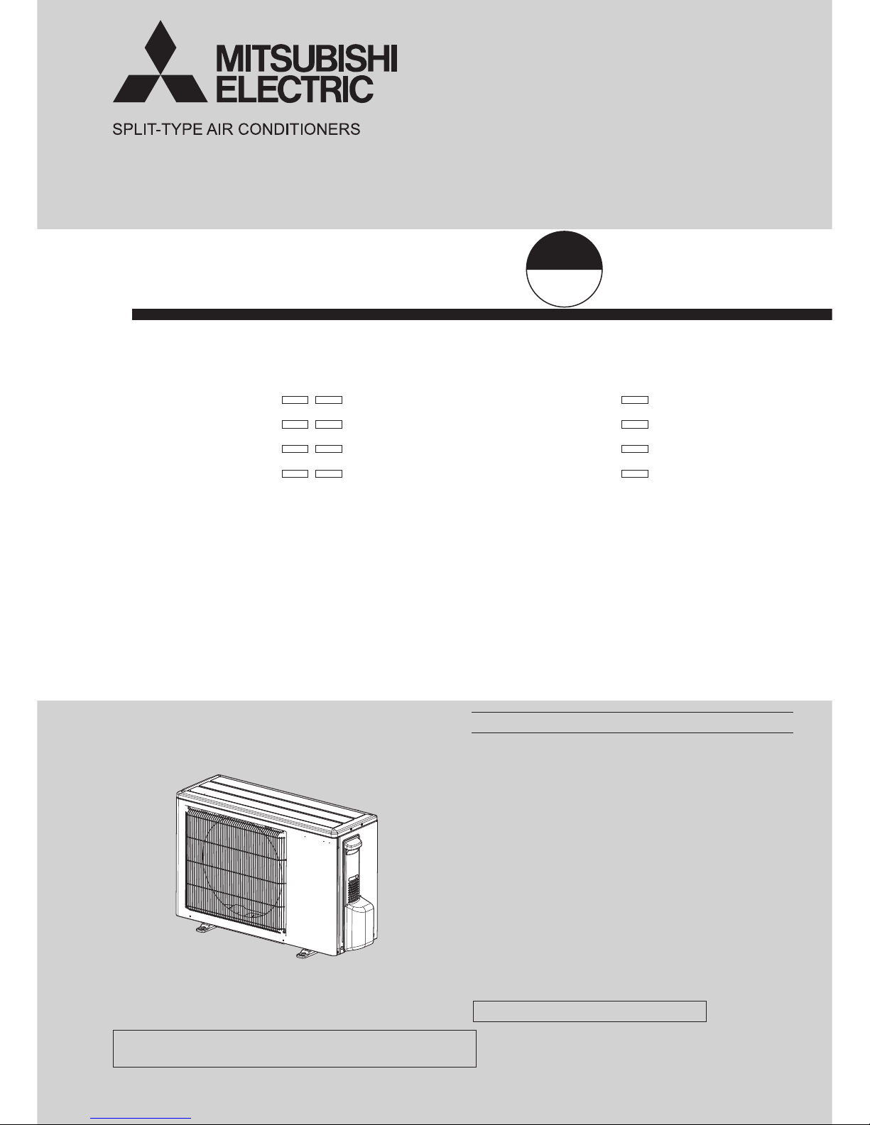
SERVICE MANUAL
OUTDOOR UNIT
NOTE:
RoHS compliant products have <G> mark on the spec name plate.
CONTENTS
1. TECHNICAL CHANGES ···································2
2. SERVICING PRECAUTIONS FOR UNITS
USING REFRIGERANT R32 ····························· 3
3. PART NAMES AND FUNCTIONS ····················· 5
4. SPECIFICATION ················································ 6
5. NOISE CRITERIA CURVES ······························ 7
6. OUTLINES AND DIMENSIONS ························ 9
7. WIRING DIAGRAM ·········································· 10
8. REFRIGERANT SYSTEM DIAGRAM ············· 13
9. PERFORMANCE CURVES ····························· 15
10. ACTUA TOR CONTROL ··································· 29
11. SERVICE FUNCTIONS ···································· 30
12. TROUBLESHOOTING ····································· 31
13. DISASSEMBLY INSTRUCTIONS ···················· 51
Models
MUZ-AP25VG
-
E1,
ET1
MUZ-AP25VGH
-
E1
MUZ-AP35VG
-
E1,
ET1
MUZ-AP35VGH
-
E1
MUZ-AP42VG
-
E1,
ET1
MUZ-AP42VGH
-
E1
MUZ-AP50VG
-
E1,
ET1
MUZ-AP50VGH
-
E1
MUZ-AP25VG
MUZ-AP35VG
MUZ-AP42VG
MUZ-AP25VGH
MUZ-AP35VGH
MUZ-AP42VGH
Page 2
2
MUZ-AP25VG
-
E1, ET1
MUZ-AP35VG
-
E1, ET1
MUZ-AP42VG
-
E1, ET1
MUZ-AP50VG
-
E1, ET1
MUZ-AP25VGH
-
E1
MUZ-AP35VGH
-
E1
MUZ-AP42VGH
-
E1
MUZ-AP50VGH
-
E1
1. New model
<Preparation before the repair service>
Prepare the proper tools.
Prepare the proper protectors.
Provide adequate ventilation.
After stopping the operation of the air conditioner, turn off the power-supply breaker and remove the power plug.
Discharge the capacitor before the work involving the electric parts.
<Precautions during the repair service>
Do not perform the work involving the electric parts with wet hands.
Do not pour water into the electric parts.
Do not touch the refrigerant.
Do not touch the hot or cold areas in the refrigeration cycle.
When the repair or the inspection of the circuit needs to be done without turning off the power, exercise great caution not to
touch the live parts.
Use the specifi ed refrigerant only
Never use any refrigerant other than that specified.
Doing so may cause a burst, an explosion, or fire when the unit is being used, serviced, or disposed of.
Correct refrigerant is specified in the manuals and on the spec labels provided with our products.
We will not be held responsible for mechanical failure, system malfunction, unit breakdown or accidents caused by
failure to follow the instructions.
TECHNICAL CHANGES
1
OBH789
Page 3

3
2
SERVICING PRECAUTIONS FOR UNITS USING REFRIGERANT R32
Servicing precautions for units using refrigerant R32
WARNING
This unit uses a flammable refrigerant.
If refrigerant leaks and comes in contact with fire or heating part, it will create harmful gas and there is risk of fire.
Do not use means to accelerate the defrosting process or to clean, other than those recommended by the manufacturer.
The appliance shall be stored in a room without continuously operating ignition sources (for example: open flames, an operating gas appliance or an operating
electric heater.)
Do not pierce or burn.
Be aware that refrigerants may not contain an odor.
Pipe-work shall be protected from physical damage.
The installation of pipe-work shall be kept to a minimum.
Compliance with national gas regulations shall be observed.
Keep any required ventilation openings clear of obstruction.
Servicing shall be performed only as recommended by the manufacturer.
The appliance shall be stored so as to prevent mechanical damage from occurring.
Basic work procedures are the same as those for conventional units using refrigerant R410A.
However, pay careful attention to the following points.
1. Information on servicing
Checks on the Area
Prior to beginning work on systems containing flammable refrigerants, safety checks are necessary to ensure that the risk of ignition is minimized.
Work Procedure
Work shall be undertaken under a controlled procedure so as to minimize the risk of a flammable gas or vapor being present while the work is being performed.
General Work Area
All maintenance staff and others working in the local area shall be instructed on the nature of work being carried out. Work in confined spaces shall be avoided.
The area around the workspace shall be sectioned off. Ensure that the conditions within the area have been made safe by control of flammable material.
Checking for Presence of Refrigerant
The area shall be checked with an appropriate refrigerant detector prior to and during work, to ensure the technician is aware of potentially toxic or flammable
atmospheres. Ensure that the leak detection equipment being used is suitable for use with all applicable refrigerants, i.e. non-sparking, adequately sealed or
intrinsically safe.
Presence of Fire Extinguisher
If any hot work is to be conducted on the refrigeration equipment or any associated parts, appropriate fire extinguishing equipment shall be available to hand.
Have a dry powder or CO2 fire extinguisher adjacent to the charging area.
No Ignition Sources
No person carrying out work in relation to a refrigeration system which involves exposing any pipe work shall use any sources of ignition in such a manner that
it may lead to the risk of fire or explosion. All possible ignition sources, including cigarette smoking, should be kept sufficiently far away from the site of installa tion, repairing, removing and disposal, during which refrigerant can possibly be released to the surrounding space. Prior to work taking place, the area around
the equipment is to be surveyed to make sure that there are no flammable hazards or ignition risks. "No Smoking" signs shall be displayed.
Ventilated Area
Ensure that the area is in the open or that it is adequately ventilated before breaking into the system or conducting any hot work. A degree of ventilation shall
continue during the period that the work is carried out. The ventilation should safely disperse any released refrigerant and preferably expel it externally into the
atmosphere.
Checks on the Refrigeration Equipment
Where electrical components are being changed, they shall be fit for the purpose and to the correct specification. At all times the manufacturer's maintenance
and service guidelines shall be followed. If in doubt, consult the manufacturer's technical department for assistance.
The following checks shall be applied to installations using flammable refrigerants:
• The charge size is in accordance with the room size within which the refrigerant containing parts are installed.
• The ventilation machinery and outlets are operating adequately and are not obstructed.
• If an indirect refrigerating circuit is being used, the secondary circuit shall be checked for the presence of refrigerant.
• Marking to the equipment continues to be visible and legible. Markings and signs that are illegible shall be corrected.
• Refrigeration pipe or components are installed in a position where they are unlikely to be exposed to any substance which may corrode refrigerant containing
components, unless the components are constructed of materials which are inherently resistant to being corroded or are suitably protected against being cor roded.
Checks on Electrical Devices
Repair and maintenance to electrical components shall include initial safety checks and component inspection procedures. If a fault exists that could compro mise safety, then no electrical supply shall be connected to the circuit until it is satisfactorily dealt with. If the fault cannot be corrected immediately but it is nec essary to continue operation, an adequate temporary solution shall be used. This shall be reported to the owner of the equipment so all parties are advised.
Initial safety checks shall include that:
• capacitors are discharged: this shall be done in a safe manner to avoid possibility of sparking;
• no live electrical components and wiring are exposed while charging, recovering or purging the system;
• there is continuity of earth bonding
2. Repairs to Sealed Components
During repairs to sealed components, all electrical supplies shall be disconnected from the equipment being worked upon prior to any removal of sealed covers,
etc. If it is absolutely necessary to have an electrical supply to equipment during servicing, then a permanently operating form of leak detection shall be located
at the most critical point to warn of a potentially hazardous situation.
Particular attention shall be paid to the following to ensure that by working on electrical components, the casing is not altered in such a way that the level of
protection is affected. This shall include damage to cables, excessive number of connections, terminals not made to original specification, damage to seals,
incorrect fitting of glands, etc.
Ensure that the apparatus is mounted securely.
Ensure that seals or sealing materials have not degraded to the point that they no longer serve the purpose of preventing the ingress of flammable atmospheres.
Replacement parts shall be in accordance with the manufacturer's specifications.
3. Repair to intrinsically Safe Components
Do not apply any permanent inductive or capacitance loads to the circuit without ensuring that this will not exceed the permissible voltage and current permitted
for the equipment in use.
Intrinsically safe components are the only types that can be worked on while live in the presence of a flammable atmosphere. The test apparatus shall be at the
correct rating.
Replace components only with parts specified by the manufacturer. Other parts may result in the ignition of refrigerant in the atmosphere from a leak.
4. Cabling
Check that cabling will not be subject to wear, corrosion, excessive pressure, vibration, sharp edges or any other adverse environmental effects. The check shall
also take into account the effects of aging or continual vibration from sources such as compressors or fans.
OBH789
Page 4

4
5. Detection of Flammable Refrigerants
Under no circumstances shall potential sources of ignition be used in the searching for or detection of refrigerant leaks. A halide torch (or any other detector
using a naked flame) shall not be used.
6. Leak Detection Methods
Electronic leak detectors may be used to detect refrigerant leaks but, in the case of flammable refrigerants, the sensitivity may not be adequate, or may need
re-calibration. (Detection equipment shall be calibrated in a refrigerant-free area.) Ensure that the detector is not a potential source of ignition and is suitable
for the refrigerant used. Leak detection equipment shall be set at a percentage of the LFL of the refrigerant and shall be calibrated to the refrigerant employed,
and the appropriate percentage of gas (25 % maximum) is confirmed.
Leak detection fluids are suitable for use with most refrigerants but the use of detergents containing chlorine shall be avoided as the chlorine may react with the
refrigerant and corrode the copper pipe-work.
If a leak is suspected, all naked flames shall be removed/extinguished.
If a leakage of refrigerant is found which requires brazing, all of the refrigerant shall be recovered from the system, or isolated (by means of shut off valves) in
a part of the system remote from the leak. For appliances containing flammable refrigerants, oxygen free nitrogen (OFN) shall then be purged through the sys tem both before and during the brazing process.
7. Removal and Evacuation
When breaking into the refrigerant circuit to make repairs - or for any other purpose conventional procedures shall be used. However, for flammable refrigerants
it is important that best practice is followed since flammability is a consideration. The following procedure shall be adhered to:
▪ remove refrigerant
▪ purge the circuit with inert gas
▪ evacuate
▪ purge again with inert gas
▪ open the circuit by cutting or brazing.
The refrigerant charge shall be recovered into the correct recovery cylinders. For appliances containing flammable refrigerants, the system shall be "flushed"
with OFN to render the unit safe. This process may need to be repeated several times. Compressed air or oxygen shall not be used for purging refrigerant sys tems.
For appliances containing flammable refrigerants, flushing shall be achieved by breaking the vacuum in the system with OFN and continuing to fill until the
working pressure is achieved, then venting to atmosphere, and finally pulling down to a vacuum. This process shall be repeated until no refrigerant is within the
system. When the final OFN charge is used, the system shall be vented down to atmospheric pressure to enable work to take place. This operation is abso-
lutely vital if brazing operations on the pipe-work are to take place.
Ensure that the outlet for the vacuum pump is not close to any ignition sources and that ventilation is available.
8. Charging Procedures
In addition to conventional charging procedures, the following requirements shall be followed:
▪ Ensure that contamination of different refrigerants does not occur when using charging equipment. Hoses or lines shall be as short as possible to minimize
the amount of refrigerant contained in them.
▪ Cylinders shall be kept upright.
▪ Ensure that the refrigeration system is earthed prior to charging the system with refrigerant.
▪ Label the system when charging is complete (if not already).
▪ Extreme care shall be taken not to overfill the refrigeration system.
Prior to recharging the system, it shall be pressure-tested with the appropriate purging gas. The system shall be leak-tested on completion of charging but prior
to commissioning. A follow up leak test shall be carried out prior to leaving the site.
9. Decommissioning
Before carrying out this procedure, it is essential that the technician is completely familiar with the equipment and all its detail. It is recommended good practice
that all refrigerants are recovered safely. Prior to the task being carried out, an oil and refrigerant sample shall be taken in case analysis is required prior to re use of reclaimed refrigerant. It is essential that electrical power is available before the task is commenced.
a) Become familiar with the equipment and its operation.
b) Isolate system electrically.
c) Before attempting the procedure, ensure that:
- mechanical handling equipment is available, if required, for handling refrigerant cylinders;
- all personal protective equipment is available and being used correctly;
- the recovery process is supervised at all times by a competent person;
- recovery equipment and cylinders conform to the appropriate standards.
d) Pump down refrigerant system, if possible.
e) If a vacuum is not possible, make a manifold so that refrigerant can be removed from various parts of the system.
f) Make sure that cylinder is situated on the scales before recovery takes place.
g) Start the recovery machine and operate in accordance with manufacturer's instructions.
h) Do not overfill cylinders. (no more than 80 % volume liquid charge).
i) Do not exceed the maximum working pressure of the cylinder, even temporarily.
j) When the cylinders have been filled correctly and the process completed, make sure that the cylinders and the equipment are removed from site promptly
and all isolation valves on the equipment are closed off.
k) Recovered refrigerant shall not be charged into another refrigeration system unless it has been cleaned and checked.
10. Labeling
Equipment shall be labeled stating that it has been de-commissioned and emptied of refrigerant. The label shall be dated and signed. For appliances containing
flammable refrigerants, ensure that there are labels on the equipment stating the equipment contains flammable refrigerant.
11. Recovery
When removing refrigerant from a system, either for servicing or decommissioning, it is recommended good practice that all refrigerants are removed safely.
When transferring refrigerant into cylinders, ensure that only appropriate refrigerant recovery cylinders are employed. Ensure that the correct number of cyl inders for holding the total system charge are available. All cylinders to be used are designated for the recovered refrigerant and labeled for that refrigerant (i.e.
special cylinders for the recovery of refrigerant). Cylinders shall be complete with pressure-relief valve and associated shut-off valves in good working order.
Empty recovery cylinders are evacuated and, if possible, cooled before recovery occurs.
The recovery equipment shall be in good working order with a set of instructions concerning the equipment that is at hand and shall be suitable for the recov ery of all appropriate refrigerants including, when applicable, flammable refrigerants. In addition, a set of calibrated weighing scales shall be available and in
good working order. Hoses shall be complete with leak-free disconnect couplings and in good condition. Before using the recovery machine, check that it is in
satisfactory working order, has been properly maintained and that any associated electrical components are sealed to prevent ignition in the event of a refriger ant release. Consult manufacturer if in doubt.
The recovered refrigerant shall be returned to the refrigerant supplier in the correct recovery cylinder, and the relevant waste transfer note arranged. Do not mix
refrigerants in recovery units and especially not in cylinders.
If compressors or compressor oils are to be removed, ensure that they have been evacuated to an acceptable level to make certa
in that flammable refriger ant does not remain within the lubricant. The evacuation process shall be carried out prior to returning the compressor to the suppliers. Only electric heating to
the compressor body shall be employed to accelerate this process. When oil is drained from a system, it shall be carried out safely.
OBH789
Page 5

5
Air outlet
Drain outlet
Piping
Drain hose
Air inlet
(back and side)
MUZ-AP25VG
MUZ-AP35VG
MUZ-AP42VG
MUZ-AP25VGH
MUZ-AP35VGH
MUZ-AP42VGH
PART NAMES AND FUNCTIONS
3
ACCESSORIES
MODELS
MUZ-AP25VG
MUZ-AP35VG
MUZ-AP42VG
MUZ-AP50VG
Drain socket 1
MUZ-AP50VG
MUZ-AP50VGH
Air outlet
Drain outlet
Piping
Drain hose
Air inlet
(back and side)
OBH789
Page 6
6
1 Measured under rated operating frequency.
Outdoor model
MUZ-AP25VG
MUZ-AP25VGH
MUZ-AP35VG
MUZ-AP35VGH
MUZ-AP42VG
MUZ-AP42VGH
MUZ-AP50VG
MUZ-AP50VGH
Power supply Single phase, 230 V, 50 Hz
Capacity
Rated frequency (Min.-Max.)
Cooling
kW
2.5 (0.9 - 3.4) 3.5 (1.1 - 3.8) 4.2 (0.9 - 4.5) 5.0 (1.4 - 5.4)
Heating 3.2 (1.0 - 4.1) 4.0 (1.3 - 4.6) 5.4 (1.3 - 6.0) 5.8 (1.4 - 7.3)
Breaker Capacity A 10 16
Electrical data
Power input 1 (Set)
Cooling
W
600 990 1,300 1,550
Heating 780 1,030 1,490 1,600
Running current
1
(Set)
Cooling
A
2.9 4.5 5.8 6.9
Heating 3.6 4.7 6.6 7.0
Power factor
1 (Set)
Cooling
%
89 95 97 97
Heating 94 95 98 99
Starting current
1 (Set) A 3.6 4.7 6.6 7.0
Coeffi cient of performance
(COP) 1 (Set)
Cooling 4.17 3.54 3.23 3.23
Heating 4.10 3.88 3.62 3.63
Compressor
Model KVB073FYXMC KVB073FYXMC SVB130FBBMC SVB130FBBMT
Output W 470 470 900 900
Current
1
Cooling
A
2.50 4.10 5.42 6.39
Heating 3.14 4.20 6.05 6.41
Refrigeration oil (Model) L 0.27 (FW68S) 0.35 (FW68S)
Fan motor
Model RC0J50-NC RC0J50-RA
Current
1
Cooling
A
0.22 0.22 0.20 0.27
Heating 0.20 0.24 0.23 0.27
Dimensions W × H × D mm 800 × 550 × 285 800 × 714 × 285
Weight kg 31 31 35 40
Special remarks
Dehumidifi cation Cooling L/h 0.3 0.6 1.4 1.9
Air fl ow
1
Cooling
High
m3/h
2,178 2,178 2,058 2,430
Low 1,038 1,038 906 1,320
Heating
High 2,076 2,076 1,962 2,430
Med. 1,788 1,788 1,686 2,238
Low 1,452 1,452 1,260 1,704
Sound level
1
Cooling
dB(A)
47 49 50 52
Heating 48 50 51 52
Fan speed
Cooling
High
rpm
940 940 940 840
Low 470 470 460 490
Heating
High 900 900 900 840
Med. 780 780 780 780
Low 640 640 600 610
Fan speed regulator 3
Refrigerant fi lling capacity (R32) kg 0.55 0.55 0.70 1.00
NOTE: Test conditions are based on ISO 5151.
Cooling: Indoor Dry-bulb temperature 27°C Wet-bulb temperature 19°C
Outdoor Dry-bulb temperature 35°C Wet-bulb temperature 24°C
Heating: Indoor Dry-bulb temperature 20°C Wet-bulb temperature 15°C
Outdoor Dry-bulb temperature 7°C Wet-bulb temperature 6°C
Refrigerant piping length (one way): 5 m
SPECIFICATION
4
OBH789
Page 7
7
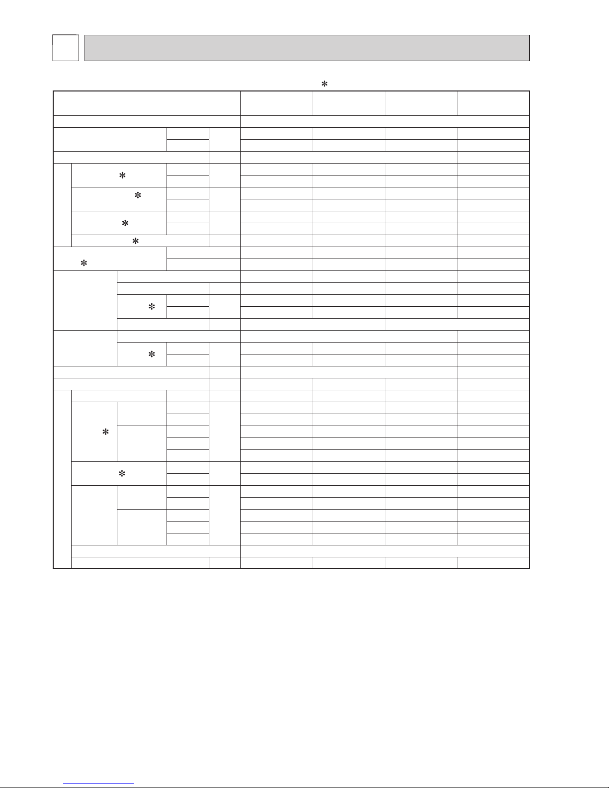
Specifi cations and rated conditions of main electric parts
Model
Item
MUZ-
AP25VG
MUZ-
AP25VGH
MUZ-
AP35VG
MUZ-
AP35VGH
MUZ-
AP42VG
MUZ-
AP42VGH
MUZ-
AP50VG
MUZ-
AP50VGH
Smoothing
capacitor
(C61) — 600 μF/ 620 μF 420 V
(C62, C63) 600 μF/ 620 μF 420 V
Diode module (DB61) 15 A 600 V 25 A 600 V
Diode module (DB65) 25 A 600 V
Fuse
(F61) 25A 250V
(F62) 15A 250V
(F701, F801, F901)
T3.15AL250V
Defrost heater (H) —
230 V
60W
—
230 V
60W
—
230 V
60W
—
230 V
130W
Power module
(IC700) 15 A 600 V 20 A 600 V
(IC932) 5 A 600 V
Expansion valve
coil
(LEV) 12 V DC
Reactor (L61) 18 mH 23 mH
Switch power
transistor
(Q821) 30 A 600 V
Current-limiting
PTC thermistor
(PTC64, PTC65)
33 Ω
Terminal block (TB1) 5 P
Relay
(X63) 3 A 250 V
(X64) 20 A 250 V
(X66) — 3 A 250 V — 3 A 250 V — 3 A 250 V — 3 A 250 V
(X69) 10 A 230 V
R.V.coil (21S4) 220 - 240 V AC
Heater protector (26H) —
Open 45°C
—
Open 45°C
—
Open 45°C
—
Open 45°C
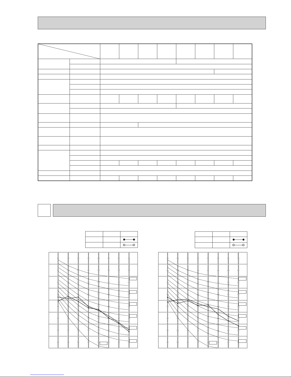
90
80
70
60
50
40
30
20
10
63 125 250 500 1000 2000 4000 8000
NC-60
NC-50
NC-40
NC-30
NC-20
NC-70
OCTAVE BAND SOUND PRESSURE LEVEL, dB re 0.0002 MICRO BAR
BAND CENTER FREQUENCIES, Hz
COOLING
FUNCTION
SPL(dB(A)) LINE
HEATING
47
48
NC-10
MUZ-AP25VG
MUZ-AP25VGH
90
80
70
60
50
40
30
20
10
63 125 250 500 1000 2000 4000 8000
NC-60
NC-50
NC-40
NC-30
NC-20
NC-70
OCTAVE BAND SOUND PRESSURE LEVEL, dB re 0.0002 MICRO BAR
BAND CENTER FREQUENCIES, Hz
COOLING
FUNCTION
SPL(dB(A))
LINE
HEATING
49
50
NC-10
MUZ-AP35VG
MUZ-AP35VGH
NOISE CRITERIA CURVES
5
OBH789
Page 8
8
90
80
70
60
50
40
30
20
10
63 125 250 500 1000 2000 4000 8000
NC-60
NC-50
NC-40
NC-30
NC-20
NC-70
OCTAVE BAND SOUND PRESSURE LEVEL, dB re 0.0002 MICRO BAR
BAND CENTER FREQUENCIES, Hz
COOLING
FUNCTION
SPL(dB(A)) LINE
HEATING
50
NC-10
51
MUZ-AP42VG
MUZ-AP42VGH
90
80
70
60
50
40
30
20
10
63 125 250 500 1000 2000 4000 8000
NC-60
NC-50
NC-40
NC-30
NC-20
NC-70
OCTAVE BAND SOUND PRESSURE LEVEL, dB re 0.0002 MICRO BAR
BAND CENTER FREQUENCIES, Hz
COOLING
FUNCTION
SPL(dB(A)) LINE
HEATING
52
NC-10
52
MUZ-AP50VG
MUZ-AP50VGH
Test conditions
Cooling: Dry-bulb temperature 35°C Wet-bulb temperature 24°C
Heating: Dry-bulb temperature 7°C Wet-bulb temperature 6°C
OUTDOOR UNIT
MICROPHONE
1 m
OBH789
Page 9
9
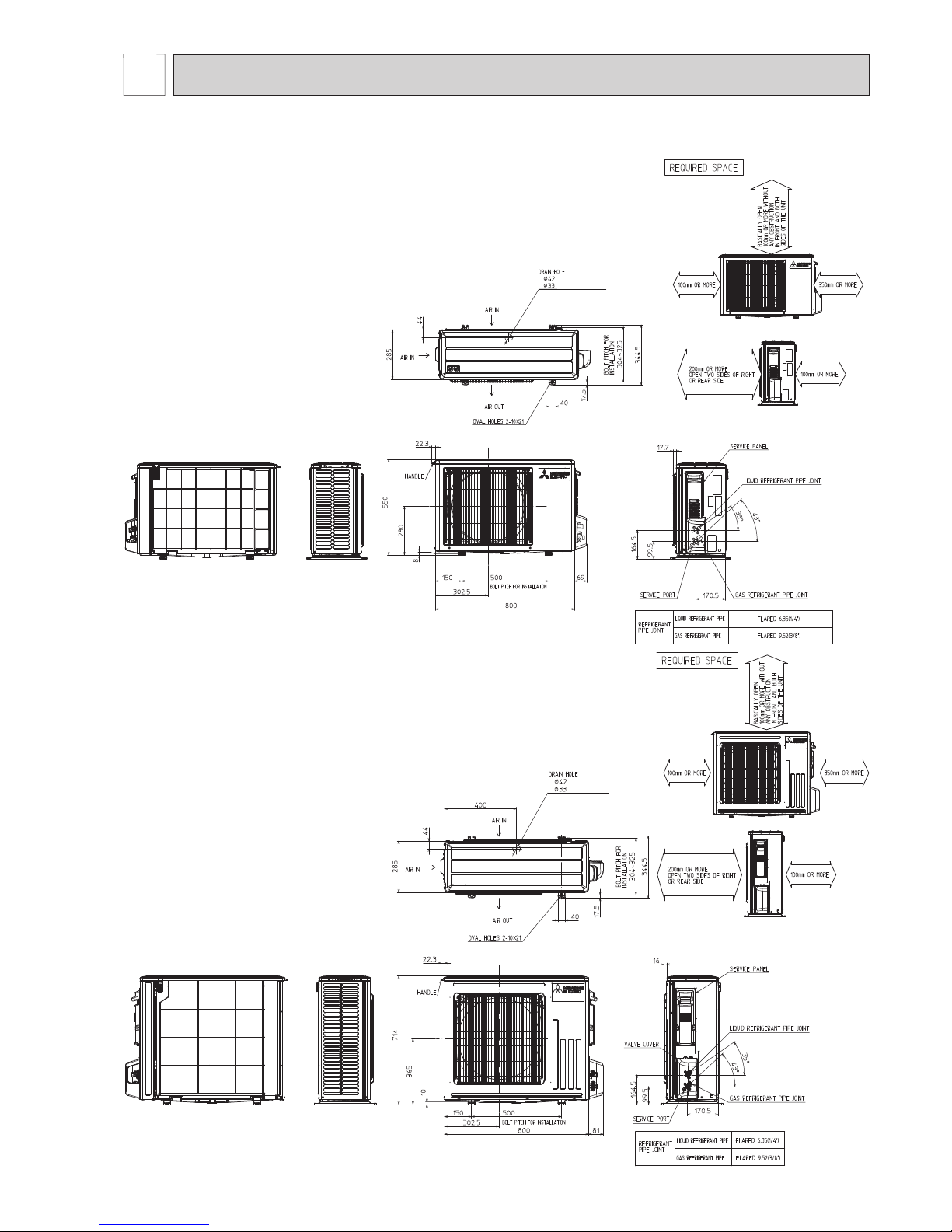
Unit: mm
MUZ-AP25VG MUZ-AP35VG MUZ-AP42VG
MUZ-AP25VGH MUZ-AP35VGH MUZ-AP42VGH
(MUZ-AP25/35/42VG)
(MUZ-AP25/35/42VGH)
MUZ-AP50VG
MUZ-AP50VGH
OUTLINES AND DIMENSIONS
6
(MUZ-AP50VG)
(MUZ-AP50VGH)
OBH789
Page 10
10
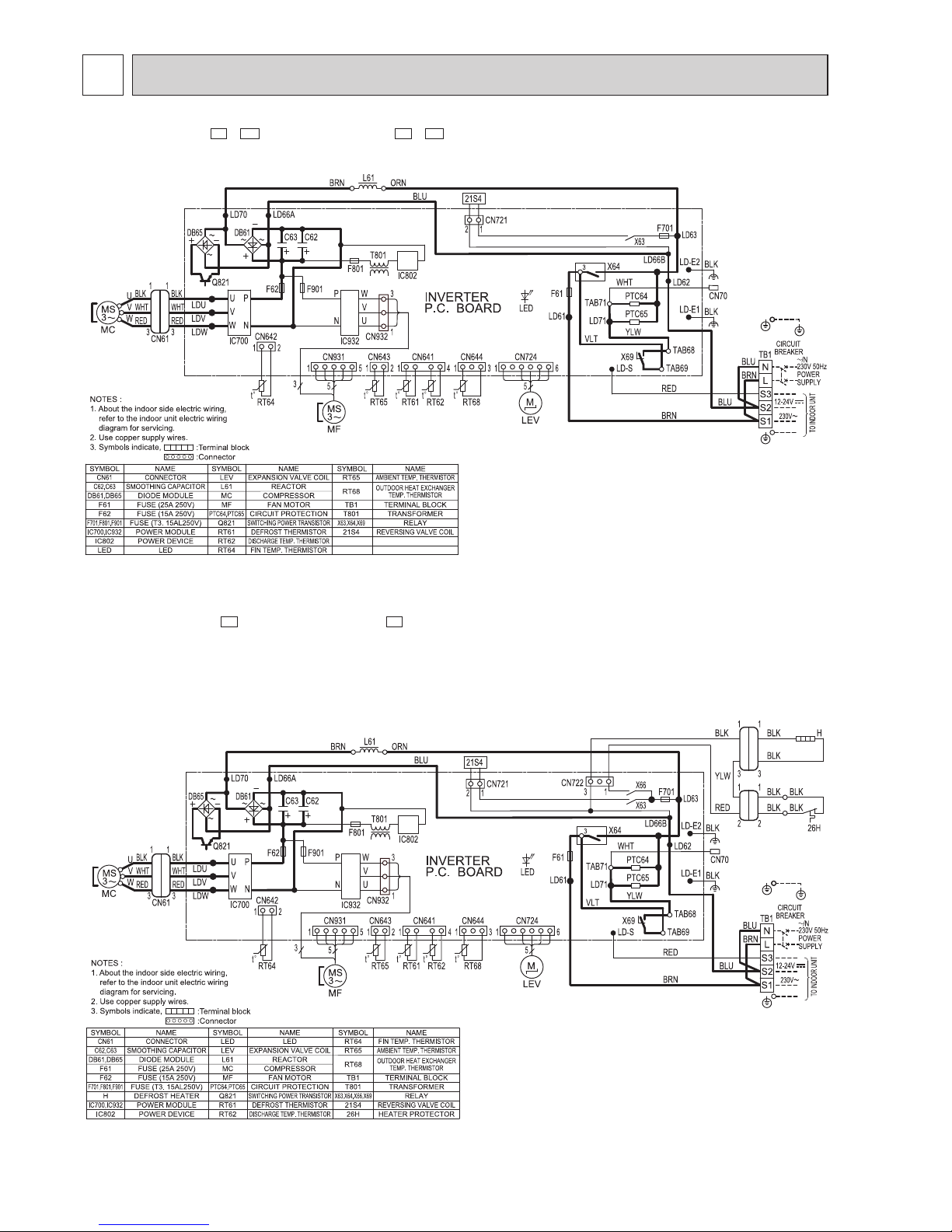
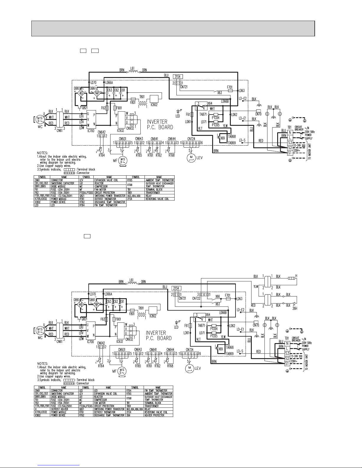
WIRING DIAGRAM
7
MUZ-AP25VG -E1,
ET1
MUZ-AP35VG -E1,
ET1
MUZ-AP25VGH -
E1
MUZ-AP35VGH -
E1
OBH789
Page 11
11
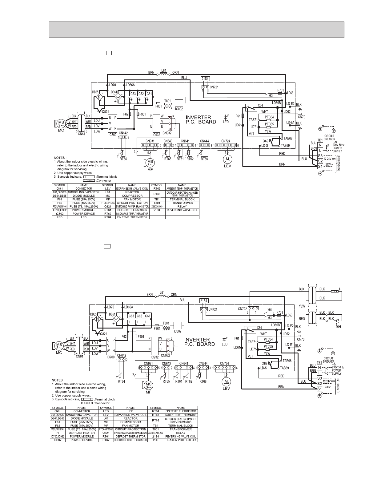
MUZ-AP42VG -E1,
ET1
MUZ-AP42VGH -
E1
OBH789
Page 12
12
MUZ-AP50VG -E1,
ET1
MUZ-AP50VGH -
E1
OBH789
Page 13

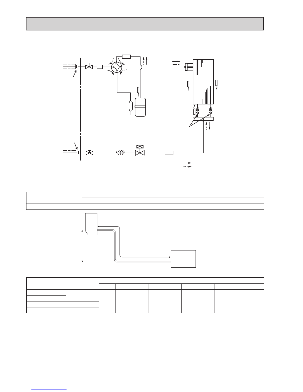
13
Unit: mm
Outdoor
heat
exchanger
Flared connection
Defrost
thermistor
RT61
Discharge
temperature
thermistor
RT62
Flared connection
Stop valve
(with strainar)
Refrigerant flow in cooling
Compressor
4-way valve
Refrigerant flow in heating
Refrigerant pipe ø9.52
(with heat insulator)
Refrigerant pipe ø6.35
(with heat insulator)
R.V. coil
heating ON
cooling OFF
Strainer
#100
LEV
Ambient
temperature
thermistor
RT65
Muffler
Capillary tube
ø4.0×ø2.4×240
Outdoor heat
exchanger
temperature
thermistor
RT68
Stop valve
(with service port)
Muffler
REFRIGERANT SYSTEM DIAGRAM
8
Unit: mm
MUZ-AP42VG
MUZ-AP42VGH
Outdoor
heat
exchanger
Flared connection
Defrost
thermistor
RT61
Discharge
temperature
thermistor
RT62
Flared connection
Stop valve
(with strainar)
Refrigerant flow in cooling
Compressor
4-way valve
Refrigerant flow in heating
Refrigerant pipe ø9.52
(with heat insulator)
Refrigerant pipe ø6.35
(with heat insulator)
R.V. coil
heating ON
cooling OFF
Strainer
#100
LEV
Ambient
temperature
thermistor
RT65
Muffler
Capillary tube
ø4.0×ø2.4×240
Outdoor heat
exchanger
temperature
thermistor
RT68
Stop valve
(with service port)
Muffler
MUZ-AP25VG MUZ-AP35VG
MUZ-AP25VGH MUZ-AP35VGH
OBH789
Page 14
14
MUZ-AP50VG
MUZ-AP50VGH
Unit: mm
Outdoor
heat
exchanger
Flared connection
Defrost
thermistor
RT61
Discharge
temperature
thermistor
RT62
Flared connection
Stop valve
(With strainer)
Stop valve
(with service port)
Capillary tube
ø
4.0×ø
2.4×240
Refrigerant flow in cooling
Compressor
4-way valve
Refrigerant flow in heating
Refrigerant pipe
ø
9.52
(with heat insulator)
Refrigerant pipe ø6.35
(with heat insulator)
LEV
R.V. coil
heating ON
cooling OFF
Muffler
Outdoor heat
exchanger
temperature
thermistor
RT68
Ambient
temperature
thermistor
RT65
Strainer
#100
Muffler
Capillary tube
ø3.0×ø2.0×210(×2)
Max. Length
A
Max. Height
difference
B
Indoor
unit
Outdoor unit
MAX. REFRIGERANT PIPING LENGTH and MAX. HEIGHT DIFFERENCE
Model
Refrigerant piping: m Piping size O.D: mm
Max. Length A Max. Height difference B Gas Liquid
MUZ-AP25/35/42/50VG(H) 20 12 9.52 6.35
ADDITIONAL REFRIGERANT CHARGE (R32: g)
Model
Outdoor unit
precharged
Refrigerant piping length (one way)
7 m 8 m 9 m 10 m 11 m 12 m 13 m 14 m 15 m 20 m
MUZ-AP25VG(H)
550
0 20 40 60 80 100 120 140 160 260
MUZ-AP35VG(H)
MUZ-AP42VG(H) 700
MUZ-AP50VG(H) 1,000
Calculation: X g = 20 g/m × (Refrigerant piping length (m) – 7)
NOTE: Refrigerant piping exceeding 7 m requires additional refrigerant charge according to the calculation.
OBH789
Page 15

15
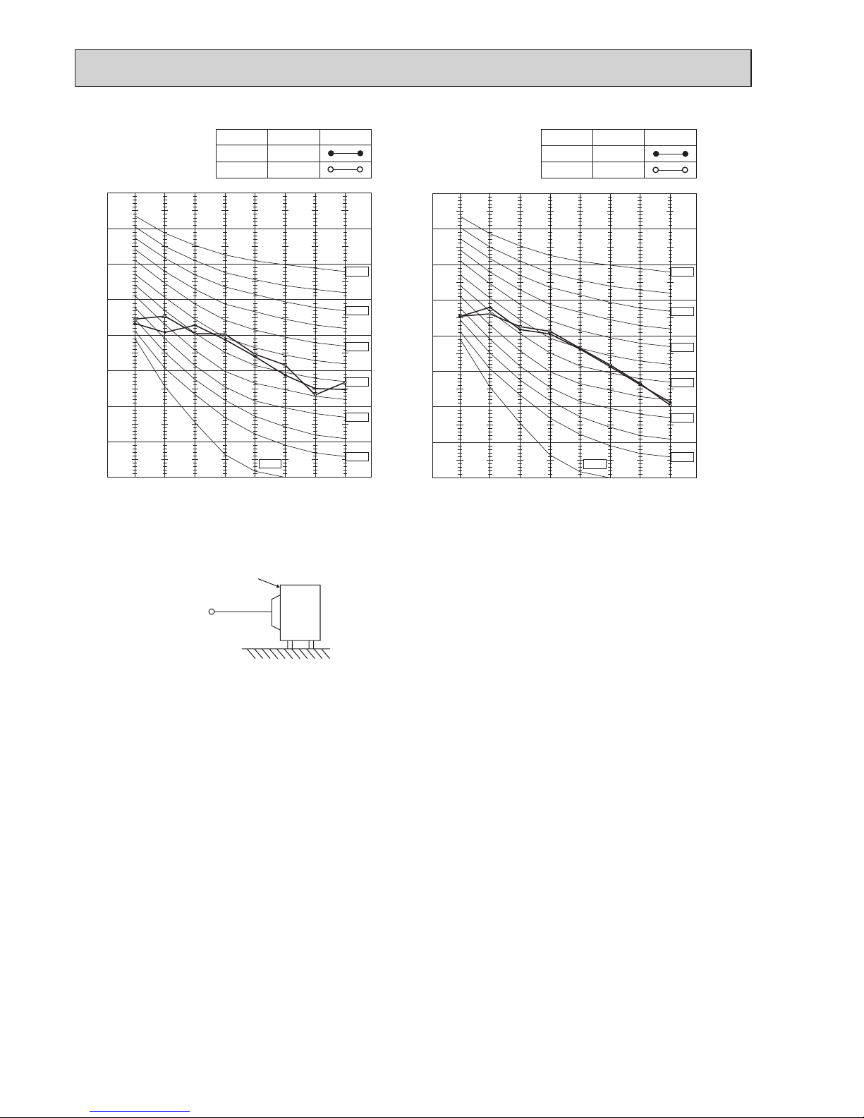
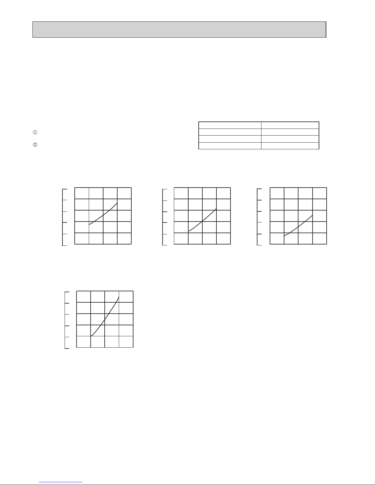
The standard specifications apply only to the operation of the air conditioner under normal conditions. Since operating conditions vary according to the areas where these units are installed, the following information has been provided to clarify the
operating characteristics of the air conditioner under the conditions indicated by the performance curve.
(1) GUARANTEED VOLTAGE
198 ~ 264 V, 50 Hz
(2) AIR FLOW
Air flow should be set at MAX.
(3) MAIN READINGS
(1) Indoor intake air wet-bulb temperature: °C [WB]
}
Cooling
(2) Indoor outlet air wet-bulb temperature: °C [WB]
(3) Outdoor intake air dry-bulb temperature: °C [DB]
(4) Total input: W
(5) Indoor intake air dry-bulb temperature: °C [DB]
}
Heating(6) Outdoor intake air wet-bulb temperature: °C [WB]
(7) Total input: W
Indoor air wet and dry bulb temperature difference on the left side of the following chart shows the difference between the
indoor intake air wet and dry bulb temperature and the indoor outlet air wet and dry bulb temperature for your reference at
service.
How to measure the indoor air wet and dry bulb temperature difference
1. Attach at least 2 sets of wet and dry bulb thermometers to the indoor air intake as shown in the figure, and at least 2 sets
of wet and dry bulb thermometers to the indoor air outlet. The thermometers must be attached to the position where air
speed is high.
2. Attach at least 2 sets of wet and dry bulb thermometers to the outdoor air intake.
Cover the thermometers to prevent direct rays of the sun.
3. Check that the air filter is cleaned.
4. Open windows and doors of room.
5. Press the EMERGENCY OPERATION switch once (twice) to start the EMERGENCY COOL (HEAT) MODE.
6. When system stabilizes after more than 15 minutes, measure temperature and take an average temperature.
7. 10 minutes later, measure temperature again and check that the temperature does not change.
MUZ-AP25VG MUZ-AP35VG MUZ-AP42VG MUZ-AP50VG
MUZ-AP25VGH MUZ-AP35VGH MUZ-AP42VGH MUZ-AP50VGH
INDOOR UNIT
OUTDOOR UNIT
Wet and dry bulb
thermometers
FRONT VIEW
Wet and dry bulb
thermometers
BACK VIEW
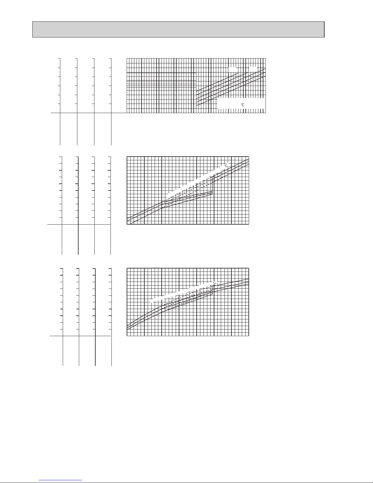
Cooling capacity (
at Rated frequency)
0.9
1.0
1.1
1.2
1.3
1.4
1.5
-10-5 0 5 1015202530354045
Outdoor intake air Dry-bulb temperature(°C)
Capacity correction factors
26
24
20
18
22
Indoor intake air Wet-bulb
temperature( )
10.7
9.9
9.0
8.2
7.4
6.7
5.9
MUZ-AP50VG
MUZ-AP42VG
MUZ-AP35VG
MUZ-AP25VG
Indoor air Wet-bulb temperature
difference (°C)
5.9
5.4
5.0
4.6
4.2
3.8
3.4
8.6
7.9
7.3
6.7
6.0
5.4
4.8
11.7
10.8
9.9
9.0
8.1
7.2
6.4
MUZ-AP25VGH
MUZ-AP50VGH
MUZ-AP42VGH
MUZ-AP35VGH
9-1. CAPACITY AND INPUT CURVES
PERFORMANCE CURVES
9
OBH789
Page 16
16
NOTE: The above broken lines are for the heating operation without any frost and defrost operation.
0.8
0.9
1.0
1.1
1.2
1.3
-10-5 0 5 1015202530354045
Outdoor intake air Dry-bulb temperature (°C)
Input correction factors
26
24
22
20
18
Indoor intake air Wet-bulb
temperature( )
Indoor air Wet-bulb temperature
difference (°C)
5.0
4.6
4.2
3.8
3.4
3.0
7.3
6.7
6.0
5.4
4.8
4.2
9.0
8.2
7.4
6.7
5.9
5.2
9.9
9.0
8.1
7.2
6.4
5.6
MUZ-AP50VG
MUZ-AP42VG
MUZ-AP35VG
MUZ-AP25VG
MUZ-AP25VGH
MUZ-AP50VGH
MUZ-AP42VGH
MUZ-AP35VGH
Total input (Cooling :
at Rated frequency
)
Indoor air Dry-bulb temperature
difference (°C)
16.2
15.0
13.7
12.5
11.2
10.0
8.7
7.5
6.2
5.0
25.2
23.3
21.3
19.4
17.5
15.5
13.6
11.6
9.7
7.8
27.1
25.0
22.9
20.8
18.8
16.7
14.6
12.5
10.4
8.3
20.3
18.7
17.2
15.6
14.0
12.5
10.9
9.4
7.8
6.2
MUZ-AP50VG
MUZ-AP42VG
MUZ-AP35VG
MUZ-AP25VG
MUZ-AP25VGH
MUZ-AP50VGH
MUZ-AP42VGH
MUZ-AP35VGH
Outdoor intake air Wet-bulb temperature (°C)
-20 -15 -10 -5 0 5 10 15
0.4
0.5
0.6
0.7
0.8
0.9
1.0
1.1
1.2
1.3
Heating capacity (
at Rated frequency)
Capacity correction factor
15
20
26
Indoor intake air Dry-bulb temperature ( )
Indoor air Dry-bulb temperature
difference (°C)
16.2
15.0
13.7
12.5
11.2
10.0
8.7
7.5
6.2
5.0
20.3
18.7
17.2
15.6
14.0
12.5
10.9
9.4
7.8
6.2
25.2
23.3
21.3
19.4
17.5
15.5
13.6
11.6
9.7
7.8
27.1
25.0
22.9
20.8
18.8
16.7
14.6
12.5
10.4
8.3
MUZ-AP50VG
MUZ-AP42VG
MUZ-AP35VG
MUZ-AP25VG
MUZ-AP25VGH
MUZ-AP50VGH
MUZ-AP42VGH
MUZ-AP35VGH
Outdoor intake air Wet-bulb temperature (°C)
-20 -15 -10 -5 0 5 10 15
0.4
0.5
0.6
0.7
0.8
0.9
1.0
1.1
1.2
1.3
Total input (Heating :
at Rated frequency
)
Input correction factor
15
20
26
Indoor intake air Dry-bulb temperature ( )
Lower limit of guaranteed operating
range in heating
MUZ-AP25/35/42/50VG: -15°C
MUZ-AP25/35/42/50VGH: -20°C
OBH789
Page 17
17
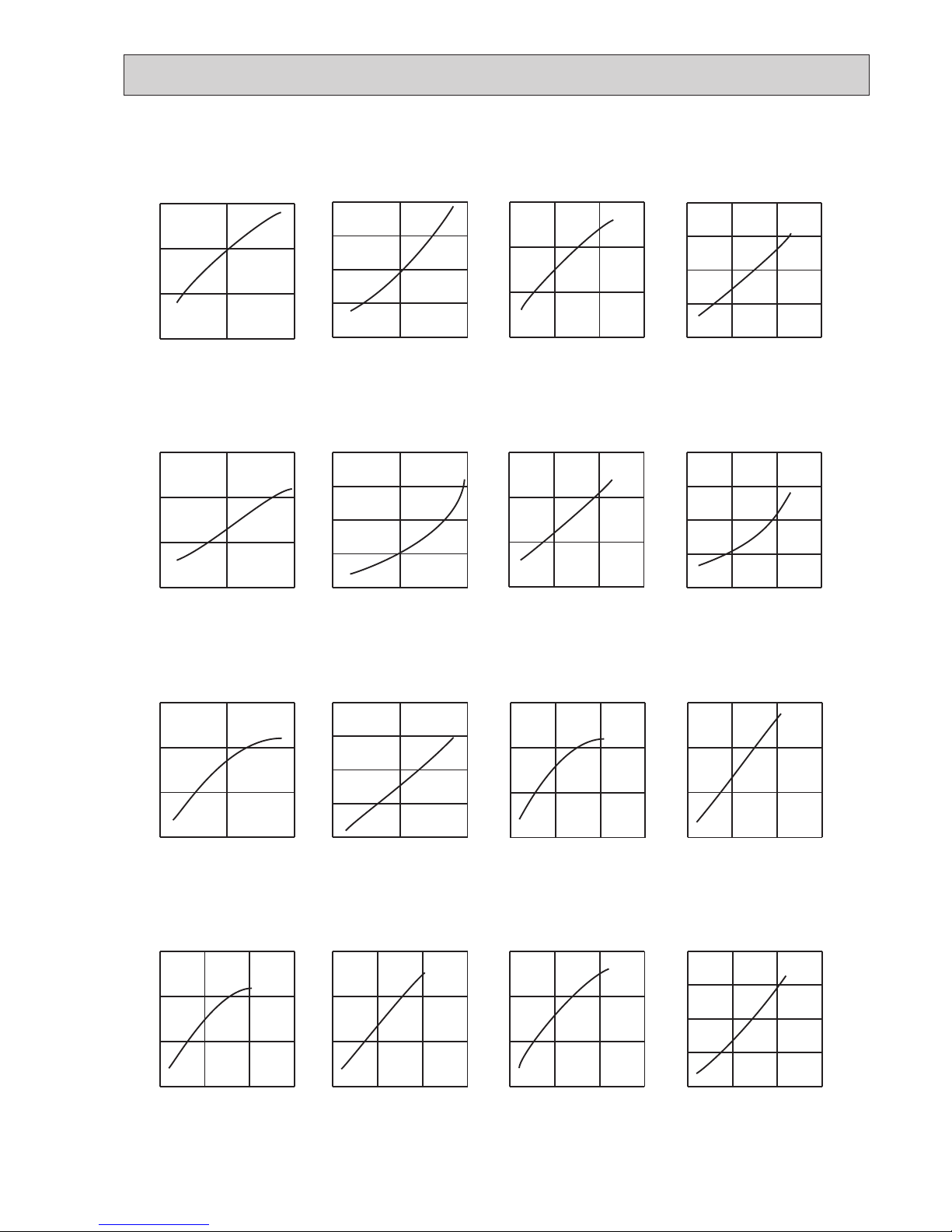
9-2. CAPACITY AND INPUT CORRECTION BY OPERATIONAL FREQUENCY OF COMPRESSOR
0 50 100
150
0.5
1.0
1.5
0 50 100
150
0.5
1.0
1.5
0 50 100
0.5
1.0
1.5
0 50 100
0.5
1.0
1.5
2.0
0 50 100
150
0.5
1.0
1.5
050100
150
0.5
1.0
1.5
0 50 100
150
0.5
1.0
1.5
0 50 100
150
0.5
1.0
1.5
2.0
0 50 100
0.5
1.0
1.5
0 50 100
0.5
1.0
1.5
2.0
0 50 100
0.5
1.0
1.5
0 50 100
0.5
1.0
1.5
2.0
0 50 100
150
0.5
1.0
1.5
050100
150
0.5
1.0
1.5
2.0
0 50 100
150
0.5
1.0
1.5
050100
150
0.5
1.0
1.5
2.0
MUZ-AP25VG
MUZ-AP25VGH
MUZ-AP35VG
MUZ-AP35VGH
Correction of Cooling capacity
Capacity correction factors
Correction of Cooling input
Input correction factors
Correction of Heating capacity
Capacity correction factors
MUZ-AP42VG
MUZ-AP42VGH
Correction of Heating input
Capacity correction factors
Correction of Cooling capacity
Capacity correction factors
Correction of Cooling input
Input correction factors
Correction of Heating capacity
Capacity correction factors
MUZ-AP50VG
MUZ-AP50VGH
Correction of Heating input
Capacity correction factors
The operatio na l freq uency
of compressor (Hz)
The operatio na l freq uency
of compressor (Hz)
The operatio na l freq uency
of compressor (Hz)
The operatio na l freq uency
of compressor (Hz)
The op erat i o na l frequency
of compressor (Hz)
The op erat i o na l frequency
of compressor (Hz)
The operational frequency
of compressor (Hz)
The operational frequency
of compressor (Hz)
Correction of Cooling ca pa ci ty
The operatio na l freq uency
of compressor (Hz)
Ca pacity correct io n f a ct o rs
Correction of Cooling input
The operational frequency
of compressor (Hz)
In put correction factors
Correction of Heati ng capacity
The operational frequency
of compressor (Hz)
Capacity correction factors
Correction of Heati ng input
The operational frequency
of compressor (Hz)
Input correction factors
Co rrect io n o f C o o ling capacity
The op erat i o na l frequency
of compressor (Hz)
Ca pacity correct io n f a ct o rs
Cor rection of Cooling input
The op erat i o na l frequency
of compressor (Hz)
Inp ut correcti o n f a ct o rs
Correction of Heati ng capacity
The operational frequency
of compressor (Hz)
Capacity correction factors
Correction of Heati ng input
The operational frequency
of compressor (Hz)
Input correction factors
OBH789
Page 18
18
15 20 25 30 35
0.5
0.7
0.9
1.1
1.3
1.5
15 20 25 30 35
0.5
0.6
0.7
0.8
0.9
1.0
15 20 25 30 35
0.5
0.7
0.9
1.1
1.3
1.5
15 20 25 30 35
0.5
0.7
0.9
1.1
1.3
1.5
(kgf/cm2 [Gauge])(MPa [Gauge])
9
7
5
11
13
15
(kgf/cm2 [Gauge])(MPa [Gauge])
7
6
5
8
9
10
(kgf/cm2 [Gauge])(MPa [Gauge])
5
9
11
7
13
15
(kgf/cm2 [Gauge])(MPa [Gauge])
7
9
3
11
13
15
50 60 70
Ambient temperature(°C)
Ambient humi di ty ( %)
50 60 70
Ambient temperature(°C)
Ambient humi di ty( %)
50 60 70
Ambient temperature(°C)
Ambient humi dity(%)
50 60 70
Ambient temperature(°C)
Ambient humi di ty( %)
Outdoor low pressure
MUZ-AP25VG MUZ-AP35VG
MUZ-AP42VG
MUZ-AP50VG
MUZ-AP25VGH
MUZ-AP35VGH MUZ-AP42VGH
MUZ-AP50VGH
COOL operation
Both indoor and outdoor unit are under the same temperature/
humidity condition.
Operation: TEST RUN OPERATION (Refer to 9-3.)
9-4. OUTDOOR LOW PRESSURE AND OUTDOOR UNIT CURRENT
Dry-bulb temperature (°C) Relative humidity (%)
20 50
25 60
30 70
9-3. HOW TO OPERATE FIXED-FREQUENCY OPERATION
<Test run operation>
1. Press EMERGENCY OPERATION switch to start COOL or HEAT mode (COOL: Press once, HEAT: Press twice).
2. Test run operation starts and continues to operate for 30 minutes.
3. Compressor operates at rated frequency in COOL mode or 58 Hz in HEAT mode.
4. Indoor fan operates at High speed.
5.
After 30 minutes, test run operation finishes and EMERGENCY OPERATION starts (operation frequency of compressor varies).
6. To cancel test run operation (EMERGENCY OPERATION), press EMERGENCY OPERATION switch or any button on
remote controller.
NOTE:
The unit of pressure has been changed to MPa on the international system of units (SI unit system)
The conversion factor is: 1 (MPa [Gauge]) = 10.2 (kgf/cm
2
[Gauge])
OBH789
Page 19

19
15 20 25 30 35
1.5
2.0
2.5
3.0
15 20 25 30 35
4
5
6
7
8
15 20 25 30 35
2.5
3.0
3.5
4.0
4.5
15 20 25 30 35
3.5
4.0
4.5
5.0
5.5
6.0
Ambient temperature(°C)
Ambient humidity(%)
Ambient temperature (°C)
Ambient humidity(%)
Ambient temperature (°C)
Ambient humidity(%)
Outdoor current (A)Outdoor current (A)
Ambient temperature (°C)
Ambient humidity(%)
Outdoor current (A)
Outdoor current (A)
MUZ-AP35VG
MUZ-AP35VGH
MUZ-AP25VG
MUZ-AP25VGH
Outdoor unit current
MUZ-AP42VG
MUZ-AP42VGH
MUZ-AP50VG
MUZ-AP50VGH
0510
15 20 25
2.0
2.5
3.0
3.5
4.0
0510
15
20 25
5.5
6.0
6.5
7.0
0510
15 20 25
2.0
2.5
3.0
3.5
4.0
0510
15
20
25
4.5
5.0
5.5
6.0
6.5
Ambient temperature (°C)
Outdoo r cu rren t ( A)
Ambient temperature (°C)
Outdoo r cu rren t ( A)
Ambient temperature (°C)
Outdoo r cu rren t ( A)
Ambient temperature (°C)
Outdoo r cu rren t ( A)
MUZ-AP35VG
MUZ-AP35VGH
MUZ-AP25VG
MUZ-AP25VGH
Outdoor unit current
MUZ-AP42VG
MUZ-AP42VGH
MUZ-AP50VG
MUZ-AP50VGH
Condition:
Operation: Test run operation (Refer to 9-3.)
HEAT operation
Indoor Outdoor
Dry bulb temperature (°C) 20.0 2 7 15 20.0
Wet bulb temperature (°C) 14.5 1 6 12 14.5
OBH789
Page 20

20
PERFORMANCE DATA COOL operation at Rated frequency
MUZ-AP25VG
MUZ-AP25VGH
CAPACITY: 2.5 kW SHF: 0.92 INPUT: 600 W
INDOOR
DB (°C)
INDOOR
WB (°C)
OUTDOOR DB (°C)
21 25 27 30
Q SHC SHF INPUT Q SHC SHF INPUT Q SHC SHF INPUT Q SHC SHF INPUT
21 18 2.94 2.17 0.74 480 2.81 2.08 0.74 504 2.70 2.00 0.74 528 2.60 1.92 0.74 552
21 20 3.06 1.90 0.62 504 2.94 1.82 0.62 534 2.85 1.77 0.62 546 2.75 1.71 0.62 570
22 18 2.94 2.29 0.78 480 2.81 2.19 0.78 504 2.70 2.11 0.78 528 2.60 2.03 0.78 552
22 20 3.06 2.02 0.66 504 2.94 1.94 0.66 534 2.85 1.88 0.66 546 2.75 1.82 0.66 570
22 22 3.19 1.72 0.54 522 3.08 1.66 0.54 555 3.00 1.62 0.54 570 2.88 1.55 0.54 594
23 18 2.94 2.41 0.82 480 2.81 2.31 0.82 504 2.70 2.21 0.82 528 2.60 2.13 0.82 552
23 20 3.06 2.14 0.70 504 2.94 2.06 0.70 534 2.85 2.00 0.70 546 2.75 1.93 0.70 570
23 22 3.19 1.85 0.58 522 3.08 1.78 0.58 555 3.00 1.74 0.58 570 2.88 1.67 0.58 594
24 18 2.94 2.53 0.86 480 2.81 2.42 0.86 504 2.70 2.32 0.86 528 2.60 2.24 0.86 552
24 20 3.06 2.27 0.74 504 2.94 2.17 0.74 534 2.85 2.11 0.74 546 2.75 2.04 0.74 570
24 22 3.19 1.98 0.62 522 3.08 1.91 0.62 555 3.00 1.86 0.62 570 2.88 1.78 0.62 594
24 24 3.35 1.68 0.50 546 3.23 1.61 0.50 576 3.15 1.58 0.50 594 3.05 1.53 0.50 624
25 18 2.94 2.64 0.90 480 2.81 2.53 0.90 504 2.70 2.43 0.90 528 2.60 2.34 0.90 552
25 20 3.06 2.39 0.78 504 2.94 2.29 0.78 534 2.85 2.22 0.78 546 2.75 2.15 0.78 570
25 22 3.19 2.10 0.66 522 3.08 2.03 0.66 555 3.00 1.98 0.66 570 2.88 1.90 0.66 594
25 24 3.35 1.81 0.54 546 3.23 1.74 0.54 576 3.15 1.70 0.54 594 3.05 1.65 0.54 624
26 18 2.94 2.76 0.94 480 2.81 2.64 0.94 504 2.70 2.54 0.94 528 2.60 2.44 0.94 552
26 20 3.06 2.51 0.82 504 2.94 2.41 0.82 534 2.85 2.34 0.82 546 2.75 2.26 0.82 570
26 22 3.19 2.23 0.70 522 3.08 2.15 0.70 555 3.00 2.10 0.70 570 2.88 2.01 0.70 594
26 24 3.35 1.94 0.58 546 3.23 1.87 0.58 576 3.15 1.83 0.58 594 3.05 1.77 0.58 624
26 26 3.45 1.59 0.46 576 3.35 1.54 0.46 606 3.30 1.52 0.46 624 3.20 1.47 0.46 642
27 18 2.94 2.88 0.98 480 2.81 2.76 0.98 504 2.70 2.65 0.98 528 2.60 2.55 0.98 552
27 20 3.06 2.63 0.86 504 2.94 2.53 0.86 534 2.85 2.45 0.86 546 2.75 2.37 0.86 570
27 22 3.19 2.36 0.74 522 3.08 2.28 0.74 555 3.00 2.22 0.74 570 2.88 2.13 0.74 594
27 24 3.35 2.08 0.62 546 3.23 2.00 0.62 576 3.15 1.95 0.62 594 3.05 1.89 0.62 624
27 26 3.45 1.73 0.50 576 3.35 1.68 0.50 606 3.30 1.65 0.50 624 3.20 1.60 0.50 642
28 18 2.94 2.94 1.00 480 2.81 2.81 1.00 504 2.70 2.70 1.00 528 2.60 2.60 1.00 552
28 20 3.06 2.76 0.90 504 2.94 2.64 0.90 534 2.85 2.57 0.90 546 2.75 2.48 0.90 570
28 22 3.19 2.49 0.78 522 3.08 2.40 0.78 555 3.00 2.34 0.78 570 2.88 2.24 0.78 594
28 24 3.35 2.21 0.66 546 3.23 2.13 0.66 576 3.15 2.08 0.66 594 3.05 2.01 0.66 624
28 26 3.45 1.86 0.54 576 3.35 1.81 0.54 606 3.30 1.78 0.54 624 3.20 1.73 0.54 642
29 18 2.94 2.94 1.00 480 2.81 2.81 1.00 504 2.70 2.70 1.00 528 2.60 2.60 1.00 552
29 20 3.06 2.88 0.94 504 2.94 2.76 0.94 534 2.85 2.68 0.94 546 2.75 2.59 0.94 570
29 22 3.19 2.61 0.82 522 3.08 2.52 0.82 555 3.00 2.46 0.82 570 2.88 2.36 0.82 594
29 24 3.35 2.35 0.70 546 3.23 2.26 0.70 576 3.15 2.21 0.70 594 3.05 2.14 0.70 624
29 26 3.45 2.00 0.58 576 3.35 1.94 0.58 606 3.30 1.91 0.58 624 3.20 1.86 0.58 642
30 18 2.94 2.94 1.00 480 2.81 2.81 1.00 504 2.70 2.70 1.00 528 2.60 2.60 1.00 552
30 20 3.06 3.00 0.98 504 2.94 2.88 0.98 534 2.85 2.79 0.98 546 2.75 2.70 0.98 570
30 22 3.19 2.74 0.86 522 3.08 2.64 0.86 555 3.00 2.58 0.86 570 2.88 2.47 0.86 594
30 24 3.35 2.48 0.74 546 3.23 2.39 0.74 576 3.15 2.33 0.74 594 3.05 2.26 0.74 624
30 26 3.45 2.14 0.62 576 3.35 2.08 0.62 606 3.30 2.05 0.62 624 3.20 1.98 0.62 642
31 18 2.94 2.94 1.00 480 2.81 2.81 1.00 504 2.70 2.70 1.00 528 2.60 2.60 1.00 552
31 20 3.06 3.06 1.00 504 2.94 2.94 1.00 534 2.85 2.85 1.00 546 2.75 2.75 1.00 570
31 22 3.19 2.87 0.90 522 3.08 2.77 0.90 555 3.00 2.70 0.90 570 2.88 2.59 0.90 594
31 24 3.35 2.61 0.78 546 3.23 2.52 0.78 576 3.15 2.46 0.78 594 3.05 2.38 0.78 624
31 26 3.45 2.28 0.66 576 3.35 2.21 0.66 606 3.30 2.18 0.66 624 3.20 2.11 0.66 642
32 18 2.94 2.94 1.00 480 2.81 2.81 1.00 504 2.70 2.70 1.00 528 2.60 2.60 1.00 552
32 20 3.06 3.06 1.00 504 2.94 2.94 1.00 534 2.85 2.85 1.00 546 2.75 2.75 1.00 570
32 22 3.19 3.00 0.94 522 3.08 2.89 0.94 555 3.00 2.82 0.94 570 2.88 2.70 0.94 594
32 24 3.35 2.75 0.82 546 3.23 2.64 0.82 576 3.15 2.58 0.82 594 3.05 2.50 0.82 624
32 26 3.45 2.42 0.70 576 3.35 2.35 0.70 606 3.30 2.31 0.70 624 3.20 2.24 0.70 642
NOTE Q : Total capacity (kW) SHF : Sensible heat factor DB : Dry-bulb temperature
SHC : Sensible heat capacity (kW) INPUT : Total power input (W) WB : Wet-bulb temperature
OBH789
Page 21

21
PERFORMANCE DATA COOL operation at Rated frequency
MUZ-AP25VG
MUZ-AP25VGH
CAPACITY: 2.5 kW SHF: 0.92 INPUT: 600 W
INDOOR
DB (°C)
INDOOR
WB (°C)
OUTDOOR DB (°C)
35 40 46
Q SHC SHF INPUT Q SHC SHF INPUT Q SHC SHF INPUT
21 18 2.45 1.81 0.74 588 2.25 1.67 0.74 624 2.08 1.54 0.74 648
21 20 2.58 1.60 0.62 612 2.40 1.49 0.62 642 2.23 1.38 0.62 678
22 18 2.45 1.91 0.78 588 2.25 1.76 0.78 624 2.08 1.62 0.78 648
22 20 2.58 1.70 0.66 612 2.40 1.58 0.66 642 2.23 1.47 0.66 678
22 22 2.73 1.47 0.54 636 2.55 1.38 0.54 672 2.38 1.28 0.54 696
23 18 2.45 2.01 0.82 588 2.25 1.85 0.82 624 2.08 1.70 0.82 648
23 20 2.58 1.80 0.70 612 2.40 1.68 0.70 642 2.23 1.56 0.70 678
23 22 2.73 1.58 0.58 636 2.55 1.48 0.58 672 2.38 1.38 0.58 696
24 18 2.45 2.11 0.86 588 2.25 1.94 0.86 624 2.08 1.78 0.86 648
24 20 2.58 1.91 0.74 612 2.40 1.78 0.74 642 2.23 1.65 0.74 678
24 22 2.73 1.69 0.62 636 2.55 1.58 0.62 672 2.38 1.47 0.62 696
24 24 2.88 1.44 0.50 660 2.70 1.35 0.50 690 2.55 1.28 0.50 720
25 18 2.45 2.21 0.90 588 2.25 2.03 0.90 624 2.08 1.87 0.9 648
25 20 2.58 2.01 0.78 612 2.40 1.87 0.78 642 2.23 1.74 0.78 678
25 22 2.73 1.80 0.66 636 2.55 1.68 0.66 672 2.38 1.57 0.66 696
25 24 2.88 1.55 0.54 660 2.70 1.46 0.54 690 2.55 1.38 0.54 720
26 18 2.45 2.30 0.94 588 2.25 2.12 0.94 624 2.08 1.95 0.94 648
26 20 2.58 2.11 0.82 612 2.40 1.97 0.82 642 2.23 1.82 0.82 678
26 22 2.73 1.91 0.70 636 2.55 1.79 0.70 672 2.38 1.66 0.70 696
26 24 2.88 1.67 0.58 660 2.70 1.57 0.58 690 2.55 1.48 0.58 720
26 26 3.03 1.39 0.46 684 2.85 1.31 0.46 714 2.68 1.23 0.46 744
27 18 2.45 2.40 0.98 588 2.25 2.21 0.98 624 2.08 2.03 0.98 648
27 20 2.58 2.21 0.86 612 2.40 2.06 0.86 642 2.23 1.91 0.86 678
27 22 2.73 2.02 0.74 636 2.55 1.89 0.74 672 2.38 1.76 0.74 696
27 24 2.88 1.78 0.62 660 2.70 1.67 0.62 690 2.55 1.58 0.62 720
27 26 3.03 1.51 0.50 684 2.85 1.43 0.50 714 2.68 1.34 0.50 744
28 18 2.45 2.45 1.00 588 2.25 2.25 1.00 624 2.08 2.08 1.00 648
28 20 2.58 2.32 0.90 612 2.40 2.16 0.90 642 2.23 2.00 0.90 678
28 22 2.73 2.13 0.78 636 2.55 1.99 0.78 672 2.38 1.85 0.78 696
28 24 2.88 1.90 0.66 660 2.70 1.78 0.66 690 2.55 1.68 0.66 720
28 26 3.03 1.63 0.54 684 2.85 1.54 0.54 714 2.68 1.44 0.54 744
29 18 2.45 2.45 1.00 588 2.25 2.25 1.00 624 2.08 2.08 1.00 648
29 20 2.58 2.42 0.94 612 2.40 2.26 0.94 642 2.23 2.09 0.94 678
29 22 2.73 2.23 0.82 636 2.55 2.09 0.82 672 2.38 1.95 0.82 696
29 24 2.88 2.01 0.70 660 2.70 1.89 0.70 690 2.55 1.79 0.70 720
29 26 3.03 1.75 0.58 684 2.85 1.65 0.58 714 2.68 1.55 0.58 744
30 18 2.45 2.45 1.00 588 2.25 2.25 1.00 624 2.08 2.08 1.00 648
30 20 2.58 2.52 0.98 612 2.40 2.35 0.98 642 2.23 2.18 0.98 678
30 22 2.73 2.34 0.86 636 2.55 2.19 0.86 672 2.38 2.04 0.86 696
30 24 2.88 2.13 0.74 660 2.70 2.00 0.74 690 2.55 1.89 0.74 720
30 26 3.03 1.88 0.62 684 2.85 1.77 0.62 714 2.68 1.66 0.62 744
31 18 2.45 2.45 1.00 588 2.25 2.25 1.00 624 2.08 2.08 1.00 648
31 20 2.58 2.58 1.00 612 2.40 2.40 1.00 642 2.23 2.23 1.00 678
31 22 2.73 2.45 0.90 636 2.55 2.30 0.90 672 2.38 2.14 0.90 696
31 24 2.88 2.24 0.78 660 2.70 2.11 0.78 690 2.55 1.99 0.78 720
31 26 3.03 2.00 0.66 684 2.85 1.88 0.66 714 2.68 1.77 0.66 744
32 18 2.45 2.45 1.00 588 2.25 2.25 1.00 624 2.08 2.08 1.00 648
32 20 2.58 2.58 1.00 612 2.40 2.40 1.00 642 2.23 2.23 1.00 678
32 22 2.73 2.56 0.94 636 2.55 2.40 0.94 672 2.38 2.23 0.94 696
32 24 2.88 2.36 0.82 660 2.70 2.21 0.82 690 2.55 2.09 0.82 720
32 26 3.03 2.12 0.70 684 2.85 2.00 0.70 714 2.68 1.87 0.70 744
NOTE Q : Total capacity (kW) SHF : Sensible heat factor DB : Dry-bulb temperature
SHC : Sensible heat capacity (kW) INPUT : Total power input (W) WB : Wet-bulb temperature
OBH789
Page 22

22
PERFORMANCE DATA COOL operation at Rated frequency
MUZ-AP35VG
MUZ-AP35VGH
CAPACITY: 3.5 kW SHF: 0.88 INPUT: 990 W
INDOOR
DB (°C)
INDOOR
WB (°C)
OUTDOOR DB (°C)
21 25 27 30
Q SHC SHF INPUT Q SHC SHF INPUT Q SHC SHF INPUT Q SHC SHF INPUT
21 18 4.11 2.88 0.70 792 3.94 2.76 0.70 832 3.78 2.65 0.70 871 3.64 2.55 0.70 911
21 20 4.29 2.49 0.58 832 4.11 2.39 0.58 881 3.99 2.31 0.58 901 3.85 2.23 0.58 941
22 18 4.11 3.04 0.74 792 3.94 2.91 0.74 832 3.78 2.80 0.74 871 3.64 2.69 0.74 911
22 20 4.29 2.66 0.62 832 4.11 2.55 0.62 881 3.99 2.47 0.62 901 3.85 2.39 0.62 941
22 22 4.46 2.23 0.50 861 4.31 2.15 0.50 916 4.20 2.10 0.50 941 4.03 2.01 0.50 980
23 18 4.11 3.21 0.78 792 3.94 3.07 0.78 832 3.78 2.95 0.78 871 3.64 2.84 0.78 911
23 20 4.29 2.83 0.66 832 4.11 2.71 0.66 881 3.99 2.63 0.66 901 3.85 2.54 0.66 941
23 22 4.46 2.41 0.54 861 4.31 2.32 0.54 916 4.20 2.27 0.54 941 4.03 2.17 0.54 980
24 18 4.11 3.37 0.82 792 3.94 3.23 0.82 832 3.78 3.10 0.82 871 3.64 2.98 0.82 911
24 20 4.29 3.00 0.70 832 4.11 2.88 0.70 881 3.99 2.79 0.70 901 3.85 2.70 0.70 941
24 22 4.46 2.59 0.58 861 4.31 2.50 0.58 916 4.20 2.44 0.58 941 4.03 2.33 0.58 980
24 24 4.69 2.16 0.46 901 4.52 2.08 0.46 950 4.41 2.03 0.46 980 4.27 1.96 0.46 1030
25 18 4.11 3.54 0.86 792 3.94 3.39 0.86 832 3.78 3.25 0.86 871 3.64 3.13 0.86 911
25 20 4.29 3.17 0.74 832 4.11 3.04 0.74 881 3.99 2.95 0.74 901 3.85 2.85 0.74 941
25 22 4.46 2.77 0.62 861 4.31 2.67 0.62 916 4.20 2.60 0.62 941 4.03 2.50 0.62 980
25 24 4.69 2.35 0.50 901 4.52 2.26 0.50 950 4.41 2.21 0.50 980 4.27 2.14 0.50 1030
26 18 4.11 3.70 0.90 792 3.94 3.54 0.90 832 3.78 3.40 0.90 871 3.64 3.28 0.90 911
26 20 4.29 3.34 0.78 832 4.11 3.21 0.78 881 3.99 3.11 0.78 901 3.85 3.00 0.78 941
26 22 4.46 2.95 0.66 861 4.31 2.84 0.66 916 4.20 2.77 0.66 941 4.03 2.66 0.66 980
26 24 4.69 2.53 0.54 901 4.52 2.44 0.54 950 4.41 2.38 0.54 980 4.27 2.31 0.54 1030
26 26 4.83 2.03 0.42 950 4.69 1.97 0.42 1000 4.62 1.94 0.42 1030 4.48 1.88 0.42 1059
27 18 4.11 3.87 0.94 792 3.94 3.70 0.94 832 3.78 3.55 0.94 871 3.64 3.42 0.94 911
27 20 4.29 3.52 0.82 832 4.11 3.37 0.82 881 3.99 3.27 0.82 901 3.85 3.16 0.82 941
27 22 4.46 3.12 0.70 861 4.31 3.01 0.70 916 4.20 2.94 0.70 941 4.03 2.82 0.70 980
27 24 4.69 2.72 0.58 901 4.52 2.62 0.58 950 4.41 2.56 0.58 980 4.27 2.48 0.58 1030
27 26 4.83 2.22 0.46 950 4.69 2.16 0.46 1000 4.62 2.13 0.46 1030 4.48 2.06 0.46 1059
28 18 4.11 4.03 0.98 792 3.94 3.86 0.98 832 3.78 3.70 0.98 871 3.64 3.57 0.98 911
28 20 4.29 3.69 0.86 832 4.11 3.54 0.86 881 3.99 3.43 0.86 901 3.85 3.31 0.86 941
28 22 4.46 3.30 0.74 861 4.31 3.19 0.74 916 4.20 3.11 0.74 941 4.03 2.98 0.74 980
28 24 4.69 2.91 0.62 901 4.52 2.80 0.62 950 4.41 2.73 0.62 980 4.27 2.65 0.62 1030
28 26 4.83 2.42 0.50 950 4.69 2.35 0.50 1000 4.62 2.31 0.50 1030 4.48 2.24 0.50 1059
29 18 4.11 4.11 1.00 792 3.94 3.94 1.00 832 3.78 3.78 1.00 871 3.64 3.64 1.00 911
29 20 4.29 3.86 0.90 832 4.11 3.70 0.90 881 3.99 3.59 0.90 901 3.85 3.47 0.90 941
29 22 4.46 3.48 0.78 861 4.31 3.36 0.78 916 4.20 3.28 0.78 941 4.03 3.14 0.78 980
29 24 4.69 3.10 0.66 901 4.52 2.98 0.66 950 4.41 2.91 0.66 980 4.27 2.82 0.66 1030
29 26 4.83 2.61 0.54 950 4.69 2.53 0.54 1000 4.62 2.49 0.54 1030 4.48 2.42 0.54 1059
30 18 4.11 4.11 1.00 792 3.94 3.94 1.00 832 3.78 3.78 1.00 871 3.64 3.64 1.00 911
30 20 4.29 4.03 0.94 832 4.11 3.87 0.94 881 3.99 3.75 0.94 901 3.85 3.62 0.94 941
30 22 4.46 3.66 0.82 861 4.31 3.53 0.82 916 4.20 3.44 0.82 941 4.03 3.30 0.82 980
30 24 4.69 3.28 0.70 901 4.52 3.16 0.70 950 4.41 3.09 0.70 980 4.27 2.99 0.70 1030
30 26 4.83 2.80 0.58 950 4.69 2.72 0.58 1000 4.62 2.68 0.58 1030 4.48 2.60 0.58 1059
31 18 4.11 4.11 1.00 792 3.94 3.94 1.00 832 3.78 3.78 1.00 871 3.64 3.64 1.00 911
31 20 4.29 4.20 0.98 832 4.11 4.03 0.98 881 3.99 3.91 0.98 901 3.85 3.77 0.98 941
31 22 4.46 3.84 0.86 861 4.31 3.70 0.86 916 4.20 3.61 0.86 941 4.03 3.46 0.86 980
31 24 4.69 3.47 0.74 901 4.52 3.34 0.74 950 4.41 3.26 0.74 980 4.27 3.16 0.74 1030
31 26 4.83 2.99 0.62 950 4.69 2.91 0.62 1000 4.62 2.86 0.62 1030 4.48 2.78 0.62 1059
32 18 4.11 4.11 1.00 792 3.94 3.94 1.00 832 3.78 3.78 1.00 871 3.64 3.64 1.00 911
32 20 4.29 4.29 1.00 832 4.11 4.11 1.00 881 3.99 3.99 1.00 901 3.85 3.85 1.00 941
32 22 4.46 4.02 0.90 861 4.31 3.87 0.90 916 4.20 3.78 0.90 941 4.03 3.62 0.90 980
32 24 4.69 3.66 0.78 901 4.52 3.52 0.78 950 4.41 3.44 0.78 980 4.27 3.33 0.78 1030
32 26 4.83 3.19 0.66 950 4.69 3.10 0.66 1000 4.62 3.05 0.66 1030 4.48 2.96 0.66 1059
NOTE Q : Total capacity (kW) SHF : Sensible heat factor DB : Dry-bulb temperature
SHC : Sensible heat capacity (kW) INPUT : Total power input (W) WB : Wet-bulb temperature
OBH789
Page 23

23
PERFORMANCE DATA COOL operation at Rated frequency
MUZ-AP35VG
MUZ-AP35VGH
CAPACITY: 3.5 kW SHF: 0.88 INPUT: 990 W
INDOOR
DB (°C)
INDOOR
WB (°C)
OUTDOOR DB (°C)
35 40 46
Q SHC SHF INPUT Q SHC SHF INPUT Q SHC SHF INPUT
21 18 3.43 2.40 0.70 970 3.15 2.21 0.70 1030 2.91 2.03 0.70 1069
21 20 3.61 2.09 0.58 1010 3.36 1.95 0.58 1059 3.12 1.81 0.58 1119
22 18 3.43 2.54 0.74 970 3.15 2.33 0.74 1030 2.91 2.15 0.74 1069
22 20 3.61 2.24 0.62 1010 3.36 2.08 0.62 1059 3.12 1.93 0.62 1119
22 22 3.82 1.91 0.50 1049 3.57 1.79 0.50 1109 3.33 1.66 0.50 1148
23 18 3.43 2.68 0.78 970 3.15 2.46 0.78 1030 2.91 2.27 0.78 1069
23 20 3.61 2.38 0.66 1010 3.36 2.22 0.66 1059 3.12 2.06 0.66 1119
23 22 3.82 2.06 0.54 1049 3.57 1.93 0.54 1109 3.33 1.80 0.54 1148
24 18 3.43 2.81 0.82 970 3.15 2.58 0.82 1030 2.91 2.38 0.82 1069
24 20 3.61 2.52 0.70 1010 3.36 2.35 0.70 1059 3.12 2.18 0.70 1119
24 22 3.82 2.21 0.58 1049 3.57 2.07 0.58 1109 3.33 1.93 0.58 1148
24 24 4.03 1.85 0.46 1089 3.78 1.74 0.46 1139 3.57 1.64 0.46 1188
25 18 3.43 2.95 0.86 970 3.15 2.71 0.86 1030 2.91 2.50 0.86 1069
25 20 3.61 2.67 0.74 1010 3.36 2.49 0.74 1059 3.12 2.31 0.74 1119
25 22 3.82 2.37 0.62 1049 3.57 2.21 0.62 1109 3.33 2.06 0.62 1148
25 24 4.03 2.01 0.50 1089 3.78 1.89 0.50 1139 3.57 1.79 0.50 1188
26 18 3.43 3.09 0.90 970 3.15 2.84 0.90 1030 2.91 2.61 0.90 1069
26 20 3.61 2.81 0.78 1010 3.36 2.62 0.78 1059 3.12 2.43 0.78 1119
26 22 3.82 2.52 0.66 1049 3.57 2.36 0.66 1109 3.33 2.19 0.66 1148
26 24 4.03 2.17 0.54 1089 3.78 2.04 0.54 1139 3.57 1.93 0.54 1188
26 26 4.24 1.78 0.42 1129 3.99 1.68 0.42 1178 3.75 1.57 0.42 1228
27 18 3.43 3.22 0.94 970 3.15 2.96 0.94 1030 2.91 2.73 0.94 1069
27 20 3.61 2.96 0.82 1010 3.36 2.76 0.82 1059 3.12 2.55 0.82 1119
27 22 3.82 2.67 0.70 1049 3.57 2.50 0.70 1109 3.33 2.33 0.70 1148
27 24 4.03 2.33 0.58 1089 3.78 2.19 0.58 1139 3.57 2.07 0.58 1188
27 26 4.24 1.95 0.46 1129 3.99 1.84 0.46 1178 3.75 1.72 0.46 1228
28 18 3.43 3.36 0.98 970 3.15 3.09 0.98 1030 2.91 2.85 0.98 1069
28 20 3.61 3.10 0.86 1010 3.36 2.89 0.86 1059 3.12 2.68 0.86 1119
28 22 3.82 2.82 0.74 1049 3.57 2.64 0.74 1109 3.33 2.46 0.74 1148
28 24 4.03 2.50 0.62 1089 3.78 2.34 0.62 1139 3.57 2.21 0.62 1188
28 26 4.24 2.12 0.50 1129 3.99 2.00 0.50 1178 3.75 1.87 0.50 1228
29 18 3.43 3.43 1.00 970 3.15 3.15 1.00 1030 2.91 2.91 1.00 1069
29 20 3.61 3.24 0.90 1010 3.36 3.02 0.90 1059 3.12 2.80 0.90 1119
29 22 3.82 2.98 0.78 1049 3.57 2.78 0.78 1109 3.33 2.59 0.78 1148
29 24 4.03 2.66 0.66 1089 3.78 2.49 0.66 1139 3.57 2.36 0.66 1188
29 26 4.24 2.29 0.54 1129 3.99 2.15 0.54 1178 3.75 2.02 0.54 1228
30 18 3.43 3.43 1.00 970 3.15 3.15 1.00 1030 2.91 2.91 1.00 1069
30 20 3.61 3.39 0.94 1010 3.36 3.16 0.94 1059 3.12 2.93 0.94 1119
30 22 3.82 3.13 0.82 1049 3.57 2.93 0.82 1109 3.33 2.73 0.82 1148
30 24 4.03 2.82 0.70 1089 3.78 2.65 0.70 1139 3.57 2.50 0.70 1188
30 26 4.24 2.46 0.58 1129 3.99 2.31 0.58 1178 3.75 2.17 0.58 1228
31 18 3.43 3.43 1.00 970 3.15 3.15 1.00 1030 2.91 2.91 1.00 1069
31 20 3.61 3.53 0.98 1010 3.36 3.29 0.98 1059 3.12 3.05 0.98 1119
31 22 3.82 3.28 0.86 1049 3.57 3.07 0.86 1109 3.33 2.86 0.86 1148
31 24 4.03 2.98 0.74 1089 3.78 2.80 0.74 1139 3.57 2.64 0.74 1188
31 26 4.24 2.63 0.62 1129 3.99 2.47 0.62 1178 3.75 2.32 0.62 1228
32 18 3.43 3.43 1.00 970 3.15 3.15 1.00 1030 2.91 2.91 1.00 1069
32 20 3.61 3.61 1.00 1010 3.36 3.36 1.00 1059 3.12 3.12 1.00 1119
32 22 3.82 3.43 0.90 1049 3.57 3.21 0.90 1109 3.33 2.99 0.90 1148
32 24 4.03 3.14 0.78 1089 3.78 2.95 0.78 1139 3.57 2.78 0.78 1188
32 26 4.24 2.80 0.66 1129 3.99 2.63 0.66 1178 3.75 2.47 0.66 1228
NOTE Q : Total capacity (kW) SHF : Sensible heat factor DB : Dry-bulb temperature
SHC : Sensible heat capacity (kW) INPUT : Total power input (W) WB : Wet-bulb temperature
OBH789
Page 24

24
PERFORMANCE DATA COOL operation at Rated frequency
MUZ-AP42VG
MUZ-AP42VGH
CAPACITY: 4.2 kW SHF: 0.77 INPUT: 1300 W
INDOOR
DB (°C)
INDOOR
WB (°C)
OUTDOOR DB (°C)
21 25 27 30
Q SHC SHF INPUT Q SHC SHF INPUT Q SHC SHF INPUT Q SHC SHF INPUT
21 18 4.94 2.91 0.59 1040 4.73 2.79 0.59 1092 4.54 2.68 0.59 1144 4.37 2.58 0.59 1196
21 20 5.15 2.42 0.47 1092 4.94 2.32 0.47 1157 4.79 2.25 0.47 1183 4.62 2.17 0.47 1235
22 18 4.94 3.11 0.63 1040 4.73 2.98 0.63 1092 4.54 2.86 0.63 1144 4.37 2.75 0.63 1196
22 20 5.15 2.62 0.51 1092 4.94 2.52 0.51 1157 4.79 2.44 0.51 1183 4.62 2.36 0.51 1235
22 22 5.36 2.09 0.39 1131 5.17 2.01 0.39 1203 5.04 1.97 0.39 1235 4.83 1.88 0.39 1287
23 18 4.94 3.31 0.67 1040 4.73 3.17 0.67 1092 4.54 3.04 0.67 1144 4.37 2.93 0.67 1196
23 20 5.15 2.83 0.55 1092 4.94 2.71 0.55 1157 4.79 2.63 0.55 1183 4.62 2.54 0.55 1235
23 22 5.36 2.30 0.43 1131 5.17 2.22 0.43 1203 5.04 2.17 0.43 1235 4.83 2.08 0.43 1287
24 18 4.94 3.50 0.71 1040 4.73 3.35 0.71 1092 4.54 3.22 0.71 1144 4.37 3.10 0.71 1196
24 20 5.15 3.04 0.59 1092 4.94 2.91 0.59 1157 4.79 2.82 0.59 1183 4.62 2.73 0.59 1235
24 22 5.36 2.52 0.47 1131 5.17 2.43 0.47 1203 5.04 2.37 0.47 1235 4.83 2.27 0.47 1287
24 24 5.63 1.97 0.35 1183 5.42 1.90 0.35 1248 5.29 1.85 0.35 1287 5.12 1.79 0.35 1352
25 18 4.94 3.70 0.75 1040 4.73 3.54 0.75 1092 4.54 3.40 0.75 1144 4.37 3.28 0.75 1196
25 20 5.15 3.24 0.63 1092 4.94 3.11 0.63 1157 4.79 3.02 0.63 1183 4.62 2.91 0.63 1235
25 22 5.36 2.73 0.51 1131 5.17 2.63 0.51 1203 5.04 2.57 0.51 1235 4.83 2.46 0.51 1287
25 24 5.63 2.19 0.39 1183 5.42 2.11 0.39 1248 5.29 2.06 0.39 1287 5.12 2.00 0.39 1352
26 18 4.94 3.90 0.79 1040 4.73 3.73 0.79 1092 4.54 3.58 0.79 1144 4.37 3.45 0.79 1196
26 20 5.15 3.45 0.67 1092 4.94 3.31 0.67 1157 4.79 3.21 0.67 1183 4.62 3.10 0.67 1235
26 22 5.36 2.95 0.55 1131 5.17 2.84 0.55 1203 5.04 2.77 0.55 1235 4.83 2.66 0.55 1287
26 24 5.63 2.42 0.43 1183 5.42 2.33 0.43 1248 5.29 2.28 0.43 1287 5.12 2.20 0.43 1352
26 26 5.80 1.80 0.31 1248 5.63 1.74 0.31 1313 5.54 1.72 0.31 1352 5.38 1.67 0.31 1391
27 18 4.94 4.10 0.83 1040 4.73 3.92 0.83 1092 4.54 3.76 0.83 1144 4.37 3.63 0.83 1196
27 20 5.15 3.65 0.71 1092 4.94 3.50 0.71 1157 4.79 3.40 0.71 1183 4.62 3.28 0.71 1235
27 22 5.36 3.16 0.59 1131 5.17 3.05 0.59 1203 5.04 2.97 0.59 1235 4.83 2.85 0.59 1287
27 24 5.63 2.65 0.47 1183 5.42 2.55 0.47 1248 5.29 2.49 0.47 1287 5.12 2.41 0.47 1352
27 26 5.80 2.03 0.35 1248 5.63 1.97 0.35 1313 5.54 1.94 0.35 1352 5.38 1.88 0.35 1391
28 18 4.94 4.29 0.87 1040 4.73 4.11 0.87 1092 4.54 3.95 0.87 1144 4.37 3.80 0.87 1196
28 20 5.15 3.86 0.75 1092 4.94 3.70 0.75 1157 4.79 3.59 0.75 1183 4.62 3.47 0.75 1235
28 22 5.36 3.37 0.63 1131 5.17 3.25 0.63 1203 5.04 3.18 0.63 1235 4.83 3.04 0.63 1287
28 24 5.63 2.87 0.51 1183 5.42 2.76 0.51 1248 5.29 2.70 0.51 1287 5.12 2.61 0.51 1352
28 26 5.80 2.26 0.39 1248 5.63 2.19 0.39 1313 5.54 2.16 0.39 1352 5.38 2.10 0.39 1391
29 18 4.94 4.49 0.91 1040 4.73 4.30 0.91 1092 4.54 4.13 0.91 1144 4.37 3.97 0.91 1196
29 20 5.15 4.06 0.79 1092 4.94 3.90 0.79 1157 4.79 3.78 0.79 1183 4.62 3.65 0.79 1235
29 22 5.36 3.59 0.67 1131 5.17 3.46 0.67 1203 5.04 3.38 0.67 1235 4.83 3.24 0.67 1287
29 24 5.63 3.10 0.55 1183 5.42 2.98 0.55 1248 5.29 2.91 0.55 1287 5.12 2.82 0.55 1352
29 26 5.80 2.49 0.43 1248 5.63 2.42 0.43 1313 5.54 2.38 0.43 1352 5.38 2.31 0.43 1391
30 18 4.94 4.69 0.95 1040 4.73 4.49 0.95 1092 4.54 4.31 0.95 1144 4.37 4.15 0.95 1196
30 20 5.15 4.27 0.83 1092 4.94 4.10 0.83 1157 4.79 3.97 0.83 1183 4.62 3.83 0.83 1235
30 22 5.36 3.80 0.71 1131 5.17 3.67 0.71 1203 5.04 3.58 0.71 1235 4.83 3.43 0.71 1287
30 24 5.63 3.32 0.59 1183 5.42 3.20 0.59 1248 5.29 3.12 0.59 1287 5.12 3.02 0.59 1352
30 26 5.80 2.72 0.47 1248 5.63 2.65 0.47 1313 5.54 2.61 0.47 1352 5.38 2.53 0.47 1391
31 18 4.94 4.89 0.99 1040 4.73 4.68 0.99 1092 4.54 4.49 0.99 1144 4.37 4.32 0.99 1196
31 20 5.15 4.48 0.87 1092 4.94 4.29 0.87 1157 4.79 4.17 0.87 1183 4.62 4.02 0.87 1235
31 22 5.36 4.02 0.75 1131 5.17 3.87 0.75 1203 5.04 3.78 0.75 1235 4.83 3.62 0.75 1287
31 24 5.63 3.55 0.63 1183 5.42 3.41 0.63 1248 5.29 3.33 0.63 1287 5.12 3.23 0.63 1352
31 26 5.80 2.96 0.51 1248 5.63 2.87 0.51 1313 5.54 2.83 0.51 1352 5.38 2.74 0.51 1391
32 18 4.94 4.94 1.00 1040 4.73 4.73 1.00 1092 4.54 4.54 1.00 1144 4.37 4.37 1.00 1196
32 20 5.15 4.68 0.91 1092 4.94 4.49 0.91 1157 4.79 4.36 0.91 1183 4.62 4.20 0.91 1235
32 22 5.36 4.23 0.79 1131 5.17 4.08 0.79 1203 5.04 3.98 0.79 1235 4.83 3.82 0.79 1287
32 24 5.63 3.77 0.67 1183 5.42 3.63 0.67 1248 5.29 3.55 0.67 1287 5.12 3.43 0.67 1352
32 26 5.80 3.19 0.55 1248 5.63 3.10 0.55 1313 5.54 3.05 0.55 1352 5.38 2.96 0.55 1391
NOTE Q : Total capacity (kW) SHF : Sensible heat factor DB : Dry-bulb temperature
SHC : Sensible heat capacity (kW) INPUT : Total power input (W) WB : Wet-bulb temperature
OBH789
Page 25

25
PERFORMANCE DATA COOL operation at Rated frequency
MUZ-AP42VG
MUZ-AP42VGH
CAPACITY: 4.2 kW SHF: 0.77 INPUT: 1300 W
INDOOR
DB (°C)
INDOOR
WB (°C)
OUTDOOR DB (°C)
35 40 46
Q SHC SHF INPUT Q SHC SHF INPUT Q SHC SHF INPUT
21 18 4.12 2.43 0.59 1274 3.78 2.23 0.59 1352 3.49 2.06 0.59 1404
21 20 4.33 2.03 0.47 1326 4.03 1.90 0.47 1391 3.74 1.76 0.47 1469
22 18 4.12 2.59 0.63 1274 3.78 2.38 0.63 1352 3.49 2.20 0.63 1404
22 20 4.33 2.21 0.51 1326 4.03 2.06 0.51 1391 3.74 1.91 0.51 1469
22 22 4.58 1.79 0.39 1378 4.28 1.67 0.39 1456 3.99 1.56 0.39 1508
23 18 4.12 2.76 0.67 1274 3.78 2.53 0.67 1352 3.49 2.34 0.67 1404
23 20 4.33 2.38 0.55 1326 4.03 2.22 0.55 1391 3.74 2.06 0.55 1469
23 22 4.58 1.97 0.43 1378 4.28 1.84 0.43 1456 3.99 1.72 0.43 1508
24 18 4.12 2.92 0.71 1274 3.78 2.68 0.71 1352 3.49 2.48 0.71 1404
24 20 4.33 2.55 0.59 1326 4.03 2.38 0.59 1391 3.74 2.21 0.59 1469
24 22 4.58 2.15 0.47 1378 4.28 2.01 0.47 1456 3.99 1.88 0.47 1508
24 24 4.83 1.69 0.35 1430 4.54 1.59 0.35 1495 4.28 1.50 0.35 1560
25 18 4.12 3.09 0.75 1274 3.78 2.84 0.75 1352 3.49 2.61 0.75 1404
25 20 4.33 2.73 0.63 1326 4.03 2.54 0.63 1391 3.74 2.35 0.63 1469
25 22 4.58 2.33 0.51 1378 4.28 2.18 0.51 1456 3.99 2.03 0.51 1508
25 24 4.83 1.88 0.39 1430 4.54 1.77 0.39 1495 4.28 1.67 0.39 1560
26 18 4.12 3.25 0.79 1274 3.78 2.99 0.79 1352 3.49 2.75 0.79 1404
26 20 4.33 2.90 0.67 1326 4.03 2.70 0.67 1391 3.74 2.50 0.67 1469
26 22 4.58 2.52 0.55 1378 4.28 2.36 0.55 1456 3.99 2.19 0.55 1508
26 24 4.83 2.08 0.43 1430 4.54 1.95 0.43 1495 4.28 1.84 0.43 1560
26 26 5.08 1.58 0.31 1482 4.79 1.48 0.31 1547 4.49 1.39 0.31 1612
27 18 4.12 3.42 0.83 1274 3.78 3.14 0.83 1352 3.49 2.89 0.83 1404
27 20 4.33 3.07 0.71 1326 4.03 2.86 0.71 1391 3.74 2.65 0.71 1469
27 22 4.58 2.70 0.59 1378 4.28 2.53 0.59 1456 3.99 2.35 0.59 1508
27 24 4.83 2.27 0.47 1430 4.54 2.13 0.47 1495 4.28 2.01 0.47 1560
27 26 5.08 1.78 0.35 1482 4.79 1.68 0.35 1547 4.49 1.57 0.35 1612
28 18 4.12 3.58 0.87 1274 3.78 3.29 0.87 1352 3.49 3.03 0.87 1404
28 20 4.33 3.24 0.75 1326 4.03 3.02 0.75 1391 3.74 2.80 0.75 1469
28 22 4.58 2.88 0.63 1378 4.28 2.70 0.63 1456 3.99 2.51 0.63 1508
28 24 4.83 2.46 0.51 1430 4.54 2.31 0.51 1495 4.28 2.18 0.51 1560
28 26 5.08 1.98 0.39 1482 4.79 1.87 0.39 1547 4.49 1.75 0.39 1612
29 18 4.12 3.75 0.91 1274 3.78 3.44 0.91 1352 3.49 3.17 0.91 1404
29 20 4.33 3.42 0.79 1326 4.03 3.19 0.79 1391 3.74 2.95 0.79 1469
29 22 4.58 3.07 0.67 1378 4.28 2.87 0.67 1456 3.99 2.67 0.67 1508
29 24 4.83 2.66 0.55 1430 4.54 2.49 0.55 1495 4.28 2.36 0.55 1560
29 26 5.08 2.19 0.43 1482 4.79 2.06 0.43 1547 4.49 1.93 0.43 1612
30 18 4.12 3.91 0.95 1274 3.78 3.59 0.95 1352 3.49 3.31 0.95 1404
30 20 4.33 3.59 0.83 1326 4.03 3.35 0.83 1391 3.74 3.10 0.83 1469
30 22 4.58 3.25 0.71 1378 4.28 3.04 0.71 1456 3.99 2.83 0.71 1508
30 24 4.83 2.85 0.59 1430 4.54 2.68 0.59 1495 4.28 2.53 0.59 1560
30 26 5.08 2.39 0.47 1482 4.79 2.25 0.47 1547 4.49 2.11 0.47 1612
31 18 4.12 4.07 0.99 1274 3.78 3.74 0.99 1352 3.49 3.45 0.99 1404
31 20 4.33 3.76 0.87 1326 4.03 3.51 0.87 1391 3.74 3.25 0.87 1469
31 22 4.58 3.43 0.75 1378 4.28 3.21 0.75 1456 3.99 2.99 0.75 1508
31 24 4.83 3.04 0.63 1430 4.54 2.86 0.63 1495 4.28 2.70 0.63 1560
31 26 5.08 2.59 0.51 1482 4.79 2.44 0.51 1547 4.49 2.29 0.51 1612
32 18 4.12 4.12 1.00 1274 3.78 3.78 1.00 1352 3.49 3.49 1.00 1404
32 20 4.33 3.94 0.91 1326 4.03 3.67 0.91 1391 3.74 3.40 0.91 1469
32 22 4.58 3.62 0.79 1378 4.28 3.38 0.79 1456 3.99 3.15 0.79 1508
32 24 4.83 3.24 0.67 1430 4.54 3.04 0.67 1495 4.28 2.87 0.67 1560
32 26 5.08 2.80 0.55 1482 4.79 2.63 0.55 1547 4.49 2.47 0.55 1612
NOTE Q : Total capacity (kW) SHF : Sensible heat factor DB : Dry-bulb temperature
SHC : Sensible heat capacity (kW) INPUT : Total power input (W) WB : Wet-bulb temperature
OBH789
Page 26

26
PERFORMANCE DATA COOL operation at Rated frequency
MUZ-AP50VG
MUZ-AP50VGH
CAPACITY: 5.0 kW SHF: 0.74 INPUT: 1550 W
INDOOR
DB (°C)
INDOOR
WB (°C)
OUTDOOR DB (°C)
21 25 27 30
Q SHC SHF INPUT Q SHC SHF INPUT Q SHC SHF INPUT Q SHC SHF INPUT
21 18 5.88 3.29 0.56 1240 5.63 3.15 0.56 1302 5.40 3.02 0.56 1364 5.20 2.91 0.56 1426
21 20 6.13 2.70 0.44 1302 5.88 2.59 0.44 1380 5.70 2.51 0.44 1411 5.50 2.42 0.44 1473
22 18 5.88 3.53 0.60 1240 5.63 3.38 0.60 1302 5.40 3.24 0.60 1364 5.20 3.12 0.60 1426
22 20 6.13 2.94 0.48 1302 5.88 2.82 0.48 1380 5.70 2.74 0.48 1411 5.50 2.64 0.48 1473
22 22 6.38 2.30 0.36 1349 6.15 2.21 0.36 1434 6.00 2.16 0.36 1473 5.75 2.07 0.36 1535
23 18 5.88 3.76 0.64 1240 5.63 3.60 0.64 1302 5.40 3.46 0.64 1364 5.20 3.33 0.64 1426
23 20 6.13 3.19 0.52 1302 5.88 3.06 0.52 1380 5.70 2.96 0.52 1411 5.50 2.86 0.52 1473
23 22 6.38 2.55 0.40 1349 6.15 2.46 0.40 1434 6.00 2.40 0.40 1473 5.75 2.30 0.40 1535
24 18 5.88 4.00 0.68 1240 5.63 3.83 0.68 1302 5.40 3.67 0.68 1364 5.20 3.54 0.68 1426
24 20 6.13 3.43 0.56 1302 5.88 3.29 0.56 1380 5.70 3.19 0.56 1411 5.50 3.08 0.56 1473
24 22 6.38 2.81 0.44 1349 6.15 2.71 0.44 1434 6.00 2.64 0.44 1473 5.75 2.53 0.44 1535
24 24 6.70 2.14 0.32 1411 6.45 2.06 0.32 1488 6.30 2.02 0.32 1535 6.10 1.95 0.32 1612
25 18 5.88 4.23 0.72 1240 5.63 4.05 0.72 1302 5.40 3.89 0.72 1364 5.20 3.74 0.72 1426
25 20 6.13 3.68 0.60 1302 5.88 3.53 0.60 1380 5.70 3.42 0.60 1411 5.50 3.30 0.60 1473
25 22 6.38 3.06 0.48 1349 6.15 2.95 0.48 1434 6.00 2.88 0.48 1473 5.75 2.76 0.48 1535
25 24 6.70 2.41 0.36 1411 6.45 2.32 0.36 1488 6.30 2.27 0.36 1535 6.10 2.20 0.36 1612
26 18 5.88 4.47 0.76 1240 5.63 4.28 0.76 1302 5.40 4.10 0.76 1364 5.20 3.95 0.76 1426
26 20 6.13 3.92 0.64 1302 5.88 3.76 0.64 1380 5.70 3.65 0.64 1411 5.50 3.52 0.64 1473
26 22 6.38 3.32 0.52 1349 6.15 3.20 0.52 1434 6.00 3.12 0.52 1473 5.75 2.99 0.52 1535
26 24 6.70 2.68 0.40 1411 6.45 2.58 0.40 1488 6.30 2.52 0.40 1535 6.10 2.44 0.40 1612
26 26 6.90 1.93 0.28 1488 6.70 1.88 0.28 1566 6.60 1.85 0.28 1612 6.40 1.79 0.28 1659
27 18 5.88 4.70 0.80 1240 5.63 4.50 0.80 1302 5.40 4.32 0.80 1364 5.20 4.16 0.80 1426
27 20 6.13 4.17 0.68 1302 5.88 4.00 0.68 1380 5.70 3.88 0.68 1411 5.50 3.74 0.68 1473
27 22 6.38 3.57 0.56 1349 6.15 3.44 0.56 1434 6.00 3.36 0.56 1473 5.75 3.22 0.56 1535
27 24 6.70 2.95 0.44 1411 6.45 2.84 0.44 1488 6.30 2.77 0.44 1535 6.10 2.68 0.44 1612
27 26 6.90 2.21 0.32 1488 6.70 2.14 0.32 1566 6.60 2.11 0.32 1612 6.40 2.05 0.32 1659
28 18 5.88 4.94 0.84 1240 5.63 4.73 0.84 1302 5.40 4.54 0.84 1364 5.20 4.37 0.84 1426
28 20 6.13 4.41 0.72 1302 5.88 4.23 0.72 1380 5.70 4.10 0.72 1411 5.50 3.96 0.72 1473
28 22 6.38 3.83 0.60 1349 6.15 3.69 0.60 1434 6.00 3.60 0.60 1473 5.75 3.45 0.60 1535
28 24 6.70 3.22 0.48 1411 6.45 3.10 0.48 1488 6.30 3.02 0.48 1535 6.10 2.93 0.48 1612
28 26 6.90 2.48 0.36 1488 6.70 2.41 0.36 1566 6.60 2.38 0.36 1612 6.40 2.30 0.36 1659
29 18 5.88 5.17 0.88 1240 5.63 4.95 0.88 1302 5.40 4.75 0.88 1364 5.20 4.58 0.88 1426
29 20 6.13 4.66 0.76 1302 5.88 4.47 0.76 1380 5.70 4.33 0.76 1411 5.50 4.18 0.76 1473
29 22 6.38 4.08 0.64 1349 6.15 3.94 0.64 1434 6.00 3.84 0.64 1473 5.75 3.68 0.64 1535
29 24 6.70 3.48 0.52 1411 6.45 3.35 0.52 1488 6.30 3.28 0.52 1535 6.10 3.17 0.52 1612
29 26 6.90 2.76 0.40 1488 6.70 2.68 0.40 1566 6.60 2.64 0.40 1612 6.40 2.56 0.40 1659
30 18 5.88 5.41 0.92 1240 5.63 5.18 0.92 1302 5.40 4.97 0.92 1364 5.20 4.78 0.92 1426
30 20 6.13 4.90 0.80 1302 5.88 4.70 0.80 1380 5.70 4.56 0.80 1411 5.50 4.40 0.80 1473
30 22 6.38 4.34 0.68 1349 6.15 4.18 0.68 1434 6.00 4.08 0.68 1473 5.75 3.91 0.68 1535
30 24 6.70 3.75 0.56 1411 6.45 3.61 0.56 1488 6.30 3.53 0.56 1535 6.10 3.42 0.56 1612
30 26 6.90 3.04 0.44 1488 6.70 2.95 0.44 1566 6.60 2.90 0.44 1612 6.40 2.82 0.44 1659
31 18 5.88 5.64 0.96 1240 5.63 5.40 0.96 1302 5.40 5.18 0.96 1364 5.20 4.99 0.96 1426
31 20 6.13 5.15 0.84 1302 5.88 4.94 0.84 1380 5.70 4.79 0.84 1411 5.50 4.62 0.84 1473
31 22 6.38 4.59 0.72 1349 6.15 4.43 0.72 1434 6.00 4.32 0.72 1473 5.75 4.14 0.72 1535
31 24 6.70 4.02 0.60 1411 6.45 3.87 0.60 1488 6.30 3.78 0.60 1535 6.10 3.66 0.60 1612
31 26 6.90 3.31 0.48 1488 6.70 3.22 0.48 1566 6.60 3.17 0.48 1612 6.40 3.07 0.48 1659
32 18 5.88 5.88 1.00 1240 5.63 5.63 1.00 1302 5.40 5.40 1.00 1364 5.20 5.20 1.00 1426
32 20 6.13 5.39 0.88 1302 5.88 5.17 0.88 1380 5.70 5.02 0.88 1411 5.50 4.84 0.88 1473
32 22 6.38 4.85 0.76 1349 6.15 4.67 0.76 1434 6.00 4.56 0.76 1473 5.75 4.37 0.76 1535
32 24 6.70 4.29 0.64 1411 6.45 4.13 0.64 1488 6.30 4.03 0.64 1535 6.10 3.90 0.64 1612
32 26 6.90 3.59 0.52 1488 6.70 3.48 0.52 1566 6.60 3.43 0.52 1612 6.40 3.33 0.52 1659
NOTE Q : Total capacity (kW) SHF : Sensible heat factor DB : Dry-bulb temperature
SHC : Sensible heat capacity (kW) INPUT : Total power input (W) WB : Wet-bulb temperature
OBH789
Page 27

27
PERFORMANCE DATA COOL operation at Rated frequency
MUZ-AP50VG
MUZ-AP50VGH
CAPACITY: 5.0 kW SHF: 0.74 INPUT: 1550 W
INDOOR
DB (°C)
INDOOR
WB (°C)
OUTDOOR DB (°C)
35 40 46
Q SHC SHF INPUT Q SHC SHF INPUT Q SHC SHF INPUT
21 18 4.90 2.74 0.56 1519 4.50 2.52 0.56 1612 4.15 2.32 0.56 1674
21 20 5.15 2.27 0.44 1581 4.80 2.11 0.44 1659 4.45 1.96 0.44 1752
22 18 4.90 2.94 0.60 1519 4.50 2.70 0.60 1612 4.15 2.49 0.60 1674
22 20 5.15 2.47 0.48 1581 4.80 2.30 0.48 1659 4.45 2.14 0.48 1752
22 22 5.45 1.96 0.36 1643 5.10 1.84 0.36 1736 4.75 1.71 0.36 1798
23 18 4.90 3.14 0.64 1519 4.50 2.88 0.64 1612 4.15 2.66 0.64 1674
23 20 5.15 2.68 0.52 1581 4.80 2.50 0.52 1659 4.45 2.31 0.52 1752
23 22 5.45 2.18 0.40 1643 5.10 2.04 0.40 1736 4.75 1.90 0.40 1798
24 18 4.90 3.33 0.68 1519 4.50 3.06 0.68 1612 4.15 2.82 0.68 1674
24 20 5.15 2.88 0.56 1581 4.80 2.69 0.56 1659 4.45 2.49 0.56 1752
24 22 5.45 2.40 0.44 1643 5.10 2.24 0.44 1736 4.75 2.09 0.44 1798
24 24 5.75 1.84 0.32 1705 5.40 1.73 0.32 1783 5.10 1.63 0.32 1860
25 18 4.90 3.53 0.72 1519 4.50 3.24 0.72 1612 4.15 2.99 0.72 1674
25 20 5.15 3.09 0.60 1581 4.80 2.88 0.60 1659 4.45 2.67 0.60 1752
25 22 5.45 2.62 0.48 1643 5.10 2.45 0.48 1736 4.75 2.28 0.48 1798
25 24 5.75 2.07 0.36 1705 5.40 1.94 0.36 1783 5.10 1.84 0.36 1860
26 18 4.90 3.72 0.76 1519 4.50 3.42 0.76 1612 4.15 3.15 0.76 1674
26 20 5.15 3.30 0.64 1581 4.80 3.07 0.64 1659 4.45 2.85 0.64 1752
26 22 5.45 2.83 0.52 1643 5.10 2.65 0.52 1736 4.75 2.47 0.52 1798
26 24 5.75 2.30 0.40 1705 5.40 2.16 0.40 1783 5.10 2.04 0.40 1860
26 26 6.05 1.69 0.28 1767 5.70 1.60 0.28 1845 5.35 1.50 0.28 1922
27 18 4.90 3.92 0.80 1519 4.50 3.60 0.80 1612 4.15 3.32 0.80 1674
27 20 5.15 3.50 0.68 1581 4.80 3.26 0.68 1659 4.45 3.03 0.68 1752
27 22 5.45 3.05 0.56 1643 5.10 2.86 0.56 1736 4.75 2.66 0.56 1798
27 24 5.75 2.53 0.44 1705 5.40 2.38 0.44 1783 5.10 2.24 0.44 1860
27 26 6.05 1.94 0.32 1767 5.70 1.82 0.32 1845 5.35 1.71 0.32 1922
28 18 4.90 4.12 0.84 1519 4.50 3.78 0.84 1612 4.15 3.49 0.84 1674
28 20 5.15 3.71 0.72 1581 4.80 3.46 0.72 1659 4.45 3.20 0.72 1752
28 22 5.45 3.27 0.60 1643 5.10 3.06 0.60 1736 4.75 2.85 0.60 1798
28 24 5.75 2.76 0.48 1705 5.40 2.59 0.48 1783 5.10 2.45 0.48 1860
28 26 6.05 2.18 0.36 1767 5.70 2.05 0.36 1845 5.35 1.93 0.36 1922
29 18 4.90 4.31 0.88 1519 4.50 3.96 0.88 1612 4.15 3.65 0.88 1674
29 20 5.15 3.91 0.76 1581 4.80 3.65 0.76 1659 4.45 3.38 0.76 1752
29 22 5.45 3.49 0.64 1643 5.10 3.26 0.64 1736 4.75 3.04 0.64 1798
29 24 5.75 2.99 0.52 1705 5.40 2.81 0.52 1783 5.10 2.65 0.52 1860
29 26 6.05 2.42 0.40 1767 5.70 2.28 0.40 1845 5.35 2.14 0.40 1922
30 18 4.90 4.51 0.92 1519 4.50 4.14 0.92 1612 4.15 3.82 0.92 1674
30 20 5.15 4.12 0.80 1581 4.80 3.84 0.80 1659 4.45 3.56 0.80 1752
30 22 5.45 3.71 0.68 1643 5.10 3.47 0.68 1736 4.75 3.23 0.68 1798
30 24 5.75 3.22 0.56 1705 5.40 3.02 0.56 1783 5.10 2.86 0.56 1860
30 26 6.05 2.66 0.44 1767 5.70 2.51 0.44 1845 5.35 2.35 0.44 1922
31 18 4.90 4.70 0.96 1519 4.50 4.32 0.96 1612 4.15 3.98 0.96 1674
31 20 5.15 4.33 0.84 1581 4.80 4.03 0.84 1659 4.45 3.74 0.84 1752
31 22 5.45 3.92 0.72 1643 5.10 3.67 0.72 1736 4.75 3.42 0.72 1798
31 24 5.75 3.45 0.60 1705 5.40 3.24 0.60 1783 5.10 3.06 0.60 1860
31 26 6.05 2.90 0.48 1767 5.70 2.74 0.48 1845 5.35 2.57 0.48 1922
32 18 4.90 4.90 1.00 1519 4.50 4.50 1.00 1612 4.15 4.15 1.00 1674
32 20 5.15 4.53 0.88 1581 4.80 4.22 0.88 1659 4.45 3.92 0.88 1752
32 22 5.45 4.14 0.76 1643 5.10 3.88 0.76 1736 4.75 3.61 0.76 1798
32 24 5.75 3.68 0.64 1705 5.40 3.46 0.64 1783 5.10 3.26 0.64 1860
32 26 6.05 3.15 0.52 1767 5.70 2.96 0.52 1845 5.35 2.78 0.52 1922
NOTE Q : Total capacity (kW) SHF : Sensible heat factor DB : Dry-bulb temperature
SHC : Sensible heat capacity (kW) INPUT : Total power input (W) WB : Wet-bulb temperature
OBH789
Page 28
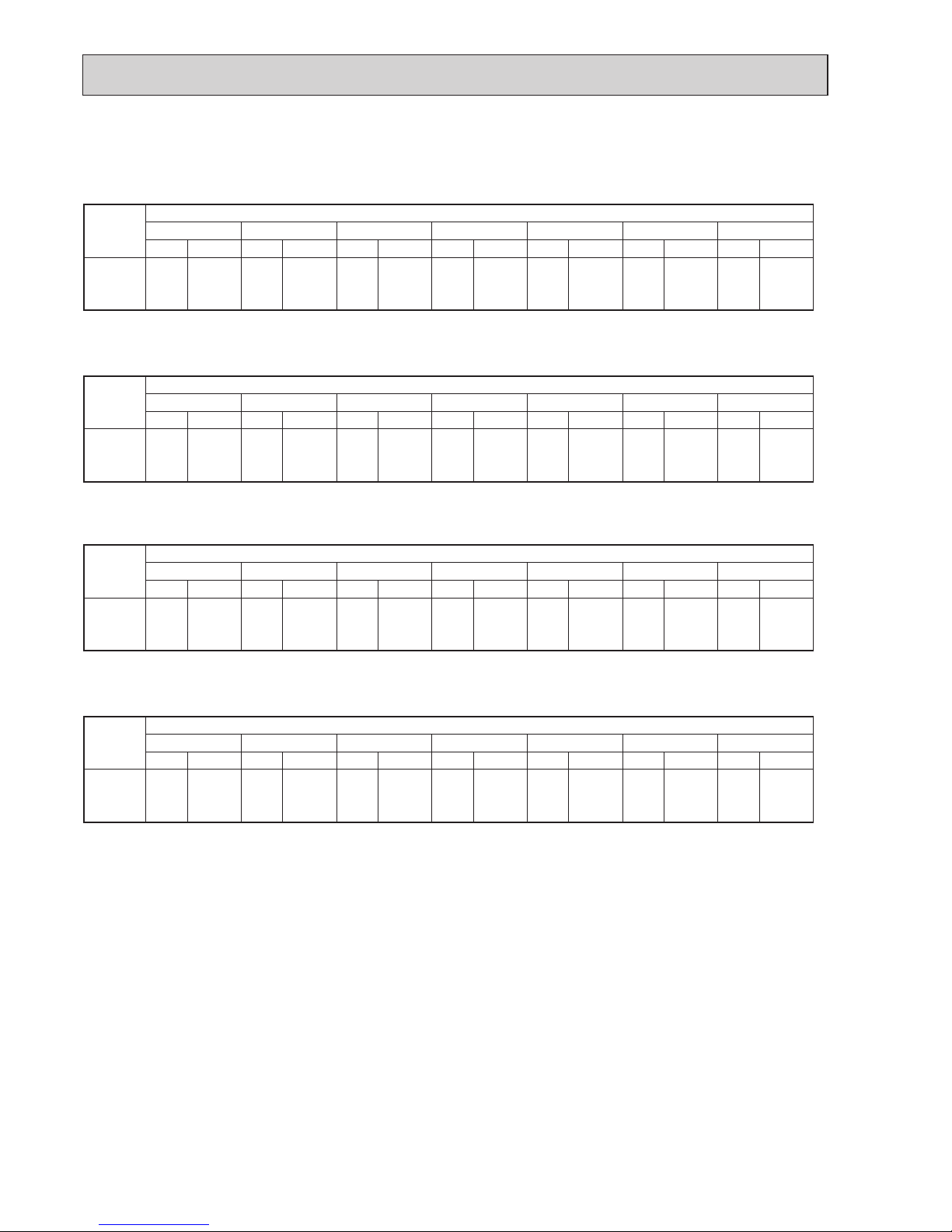
28
PERFORMANCE DATA HEAT operation at Rated frequency
MUZ-AP25VG
MUZ-AP25VGH
CAPACITY: 3.2 kW INPUT: 780 W
INDOOR
DB (°C)
OUTDOOR WB (°C)
-10 -5 0 5 10 15 20
Q INPUT Q INPUT Q INPUT Q INPUT Q INPUT Q INPUT Q INPUT
15 2.02 507 2.43 608 2.85 686 3.26 741 3.68 788 4.06 811 4.48 827
21 1.92 546 2.30 647 2.72 718 3.10 772 3.52 811 3.90 835 4.30 866
26 1.73 585 2.14 686 2.53 757 2.94 811 3.36 850 3.74 874 4.16 897
MUZ-AP35VG
MUZ-AP35VGH
CAPACITY: 4.0 kW INPUT: 1030 W
INDOOR
DB (°C)
OUTDOOR WB (°C)
-10 -5 0 5 10 15 20
Q INPUT Q INPUT Q INPUT Q INPUT Q INPUT Q INPUT Q INPUT
15 2.52 670 3.04 803 3.56 906 4.08 979 4.60 1040 5.08 1071 5.60 1092
21 2.40 721 2.88 855 3.40 948 3.88 1020 4.40 1071 4.88 1102 5.38 1143
26 2.16 773 2.68 906 3.16 999 3.68 1071 4.20 1123 4.68 1154 5.20 1185
MUZ-AP42VG
MUZ-AP42VGH
CAPACITY: 5.4 kW INPUT: 1490 W
INDOOR
DB (°C)
OUTDOOR WB (°C)
-10 -5 0 5 10 15 20
Q INPUT Q INPUT Q INPUT Q INPUT Q INPUT Q INPUT Q INPUT
15 3.40 969 4.10 1162 4.81 1311 5.51 1416 6.21 1505 6.86 1550 7.56 1579
21 3.24 1043 3.89 1237 4.59 1371 5.24 1475 5.94 1550 6.59 1594 7.26 1654
26 2.92 1118 3.62 1311 4.27 1445 4.97 1550 5.67 1624 6.32 1669 7.02 1714
MUZ-AP50VG
MUZ-AP50VGH
CAPACITY: 5.8 kW INPUT: 1600 W
INDOOR
DB (°C)
OUTDOOR WB (°C)
-10 -5 0 5 10 15 20
Q INPUT Q INPUT Q INPUT Q INPUT Q INPUT Q INPUT Q INPUT
15 3.65 1040 4.41 1248 5.16 1408 5.92 1520 6.67 1616 7.37 1664 8.12 1696
21 3.48 1120 4.18 1328 4.93 1472 5.63 1584 6.38 1664 7.08 1712 7.80 1776
26 3.13 1200 3.89 1408 4.58 1552 5.34 1664 6.09 1744 6.79 1792 7.54 1840
NOTE: Q : Total capacity (kW) INPUT : Total power input (W) DB: Dry-bulb temperature WB: Wet-bulb temperature
OBH789
Page 29
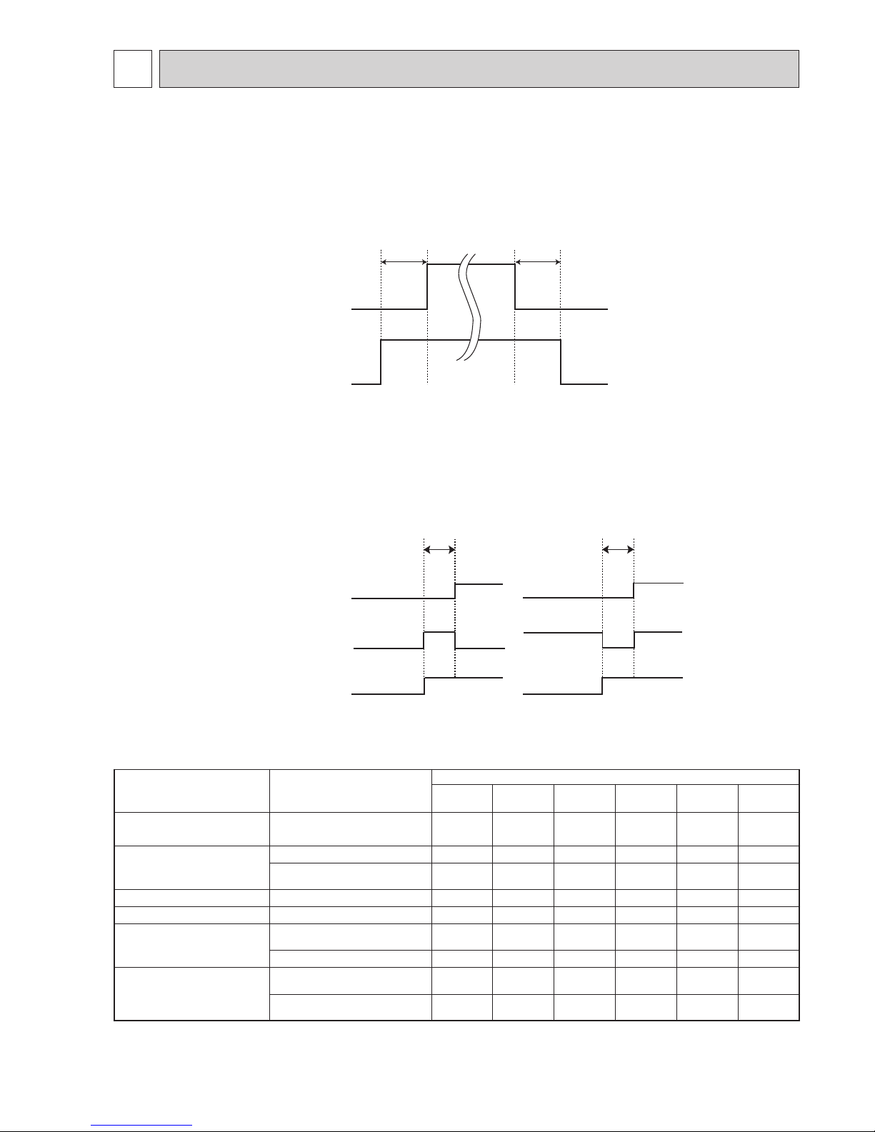
29
10-2. R.V. COIL CONTROL
Heating
. . . . . . . . . . . . . . . . .
ON
Cooling
. . . . . . . . . . . . . . . . .
OFF
Dry
. . . . . . . . . . . . . . . . . . . .
OFF
NOTE: The 4-way valve reverses for 5 seconds right before start-up of the compressor.
ON
OFF
ON
OFF
Outdoor fan
motor
Compressor
5 seconds 15 seconds
ON
OFF
Compressor
Outdoor fan
motor
R.V.coil
ON
OFF
ON
OFF
<COOL>
5 seconds
<HEAT>
5 seconds
10-1. OUTDOOR FAN MOTOR CONTROL
The fan motor turns ON/OFF, interlocking with the compressor.
[ON] The fan motor turns ON 5 seconds before the compressor starts up.
[OFF] The fan motor turns OFF 15 seconds after the compressor has stopped running.
10-3. RELATION BETWEEN MAIN SENSOR AND ACTUATOR
Sensor Purpose
Actuator
Compressor
LEV
Outdoor fan
motor
R.V. coil
Indoor fan
motor
Defrost
heater
Discharge temperature
thermistor
Protection
○○
Indoor coil temperature
thermistor
Cooling: Coil frost prevention
○
Heating: High pressure protection
○○
Defrost thermistor Heating: Defrosting
○○○○○
Fin temperature thermistor Protection
○○
Ambient temperature
thermistor
Cooling: Low ambient temperature operation
○○○
Heating: Defrosting (Heater)
○
Outdoor heat exchanger temperature thermistor
Cooling: Low ambient temperature operation
○○○
Cooling: High pressure protection
○○○
ACTUATOR CONTROL
10
MUZ-AP25VG MUZ-AP35VG MUZ-AP42VG MUZ-AP50VG
MUZ-AP25VGH MUZ-AP35VGH MUZ-AP42VGH MUZ-AP50VGH
OBH789
Page 30

30
SERVICE FUNCTIONS
11
11-1. CHANGE IN DEFROST SETTING
Changing defrost finish temperature
<JS> To change the defrost finish temperature, cut/solder the JS wire of the outdoor inverter P.C. board.
(Refer to 12-6-1.)
Jumper wire Defrost fi nish temperature (°C)
JS
Soldered (Initial setting) 5
None (Cut) 10
11-2. PRE-HEAT CONTROL SETTING
PRE-HEAT CONTROL
When moisture gets into the refrigerant cycle, it may interfere the start-up of the compressor at low outside temperature.
The pre-heat control prevents this interference. The pre-heat control turns ON when the discharge temperature thermistor is 20°C or below. When the pre-heat control turns ON, the compressor is energized. (About 50 W)
Pre-heat control setting
<JK>
ON: To activate the pre-heat control, cut the JK wire of the inverter P.C. board.
OFF: To deactivate the pre-heat control, solder the JK wire of the inverter P.C. board.
(Refer to 12-6.1)
NOTE: When the inverter P.C. board is replaced, check the jumper wires, and cut/solder them if necessary.
MUZ-AP25VG MUZ-AP35VG MUZ-AP42VG MUZ-AP50VG
MUZ-AP25VGH MUZ-AP35VGH MUZ-AP42VGH MUZ-AP50VGH
OBH789
Page 31

31
12-1. CAUTIONS ON TROUBLESHOOTING
1. Before troubleshooting, check the following
1) Check the power supply voltage.
2) Check the indoor/outdoor connecting wire for miswiring.
2. Take care of the following during servicing
1) Before servicing the air conditioner, be sure to turn OFF the main unit first with the remote controller, and then after
confirming the horizontal vane is closed, turn OFF the breaker and/or disconnect the power plug.
2) Be sure to turn OFF the power supply before removing the front panel, the cabinet, the top panel, and the electronic
control P.C. board.
3) When removing the electrical parts, be careful of the residual voltage of smoothing capacitor.
4) When removing the electronic control P.C. board, hold the edge of the board with care NOT to apply stress on the
components.
5) When connecting or disconnecting the connectors, hold the connector housing. DO NOT pull the lead wires.
TROUBLESHOOTING
12
3. Troubleshooting procedure
1) Check if the OPERATION INDICATOR lamp on the indoor unit is flashing on and off to indicate an abnormality.
To make sure, check how many times the OPERATION INDICATOR lamp is flashing on and off before starting ser-
vice work.
2) Before servicing, check that the connector and terminal are connected properly.
3) When the electronic control P.C. board seems to be defective, check the copper foil pattern for disconnection and the
components for bursting and discoloration.
4) Refer to 12-2 and 12-3.
Lead wiring
Connector housing
<Incorrect>
<Correct>
MUZ-AP25VG MUZ-AP35VG MUZ-AP42VG MUZ-AP50VG
MUZ-AP25VGH MUZ-AP35VGH MUZ-AP42VGH MUZ-AP50VGH
OBH789
Page 32

32
Outline of the function
This air conditioner can memorize the abnormal condition which has occurred once.
Even though LED indication listed on the troubleshooting check table (12-3.) disappears, the memorized failure details can be recalled.
12-2. FAILURE MODE RECALL FUNCTION
1. Flow chart of failure mode recall function for the indoor/outdoor unit
NOTE: 1. Make sure to release the failure mode recall function after it is set up, otherwise the unit cannot operate properly.
2. If the abnormal condition is not deleted from the memory, the last abnormal condition is kept memorized.
Does the upper lamp of OPERATION INDICATOR lamp on
the indoor unit blink at the interval of 0.5 seconds?
Blinks: Either indoor or outdoor unit is abnormal. Beep is
emitted at the same timing as the blinking of the upper lamp on the indoor unit.
2
Indoor unit is normal.
But the outdoor unit might be abnormal because there are some abnormalities that cannot be recalled with this way.
Check if outdoor unit is abnormal according to the detailed outdoor unit
failure mode recall function. (Refer to 12-2.2)
No
Yes
The cause of abnormality cannot be found because the abnormality does not recur.
Setting up the failure mode recall function
Turn ON the power supply.
<Preparation of the remote controller>
While pressing OPERATION SELECT button and TEMP
button on the remote
controller at the same time, press RESET button.
First, release RESET button.
Hold down the other 2 buttons for another 3 seconds. Make sure that the indicators on
the LCD screen shown in the right fi gure are all displayed. Then release the buttons.
Press STOP/OPERATE (OFF/ON) button of the remote controller (the set temperature
is displayed) with the remote controller headed towards the indoor unit.
1
Judgment of indoor/outdoor abnormality
Before blinking, does the upper lamp on the indoor unit stay
ON for 3 seconds? When it stays ON for 3 seconds (without
beep):The outdoor unit is abnormal.
The indoor unit is abnormal.
Check the blinking pattern, and identify the abnormal point by referring to the
table of indoor unit failure mode recall function. (Refer to indoor unit service
manual.)
Make sure to check at least 2 consecutive blinking cycles.
2
Releasing the failure mode recall function
Release the failure mode recall function by the following procedures.
Turn OFF the power supply and turn it ON again.
Press RESET button of the remote controller.
The outdoor unit is abnormal.
Check the blinking pattern, and identify the abnormal point by referring
to the table of outdoor unit failure mode recall function. (Refer to 12-2.3)
Make sure to check at least 2 consecutive blinking cycles.
3
Repair the failure parts.
Deleting the memorized abnormal condition
After repairing the unit, recall the failure mode again according to "Setting up the failure mode recall
function" mentioned above.
Press STOP/OPERATE (OFF/ON) button of the remote controller (the set temperature is displayed)
with the remote controller headed towards the indoor unit.
Press EMERGENCY OPERATION switch so that the memorized abnormal condition is deleted.
Release the failure mode recall function according to "Releasing the failure mode recall function"
mentioned above.
Operational procedure
Yes
(Blinks)
No
(OFF)
1. Regardless of normal or abnormal condition,
a short beep is emitted once the signal is
received.
2. Blinking pattern when the indoor unit is abnormal:
3.Blinking pattern when the outdoor unit is abnormal:
ON
OFF
Beeps
Repeated cycle Repeated cycle
ON
OFF
No beep Beeps
Repeated cycle
2.5-second OFF
Blinking at 0.5-
second interval
2.5-second OFF 3-second ON
Blinking at 0.5second interval
Beeps
Repeated cycle
2.5-second OFF
Blinking at 0.5second interval
No beep Beeps
Repeated cycle
2.5-second OFF 3-second ON
Blinking at 0.5second interval
Repeated cycle
Beeps
WEEKLY TIMER
MSZ-AP·VG(K)
OBH789
Page 33

33
2. Flow chart of the detailed outdoor unit failure mode recall function
2.Blinking pattern when outdoor unit is abnormal:
ON
OFF
No beep
Beeps
Repeated cycle
2.5-second OFF 3-second ON
Blinking at 0.5second interval
No beep Beeps
Repeated cycle
2.5-second OFF 3-second ON
Blinking at 0.5-
second interval
Repeated cycle
Does the upper lamp of OPERATION INDICATOR
lamp on the indoor unit blink at the interval of 0.5
seconds?
Blinks: The outdoor unit is abnormal. Beep is emitted
at the same timing as the blinking of the upper
lamp on the indoor unit.
2
Yes
(Blinks
)
No
(OFF)
The outdoor unit might be abnormal.
Check if outdoor unit is abnormal according to the following procedures.
Operational procedure
Make sure that the remote controller is set to the failure mode recall function.
With the remote controller headed towards the indoor unit, press TEMP
button to adjust the set temperature to 25°C. 1
1. Regardless of normal or abnormal condition, 2 short
beeps are emitted as the signal is received.
The outdoor unit is abnormal.
Check the blinking pattern, and identify the abnormal point by referring to
the table of outdoor unit failure mode recall function (12-2.3.).
Make sure to check at least 2 consecutive blinking cycles.
2
Releasing the failure mode recall function
Release the failure mode recall function by the following procedures.
Turn OFF the power supply and turn it ON again.
Press RESET button of the remote controller.
Repair the failure parts.
The outdoor unit is normal.
Release the failure mode recall function according to the left mentioned procedure.
Deleting the memorized abnormal condition
After repairing the unit, recall the failure mode again according to "Setting up the failure mode recall
function" (12-2.1.).
Press STOP/OPERATE (OFF/ON) button of the remote controller (the set temperature is displayed) with
the remote controller headed towards the indoor unit.
Press EMERGENCY OPERATION switch so that the memorized abnormal condition is deleted.
4
Release the failure mode recall function according to "Releasing the failure mode recall function" men-
tioned above.
NOTE: 1. Make sure to release the failure mode recall function after it is set up, otherwise the unit cannot operate properly.
2. If the abnormal condition is not deleted from the memory, the last abnormal condition is kept memorized.
4
The information regarding whether the
connected outdoor unit is a low-standby-
power model or a non-low-standby-power
model will also be initialized.
(Default= compatible with a low-standby-
power model)
NOTE: It takes up to 1 minute to indicate the outdoor unit abnor-
mality.
Even if the upper lamp on the indoor unit is not lighting,
keep checking at least 1 minute or longer.
OBH789
Page 34

34
3. Table of outdoor unit failure mode recall function
NOTE: Blinking patterns of this mode differ from the ones of TROUBLESHOOTING CHECK TABLE (12-3.).
Upper lamp
(Indoor unit)
Abnormal point
(Failure mode/protection)
LED indication
(Outdoor P.C. board)
Condition Remedy
Indoor/outdoor
unit failure
mode recall
function
Outdoor unit
failure mode
recall function
OFF None (Normal) — — — — —
1-time fl ash
2.5 seconds
OFF
Indoor/outdoor
communication, receiving
error
—
Any signals from the inverter P.C.
board cannot be received normally for
3 minutes.
•Refer to 12-5.
How
to check miswiring and
serial signal error.
○○
Indoor/outdoor
communication, receiving
error
—
Although the inverter P.C. board
sends signal "0", signal "1" has been
received 30 consecutive times.
•Refer to 12-5.
How
to check miswiring and
serial signal error.
2-time fl ash
2.5 seconds
OFF
Outdoor power system
—
Overcurrent protection cut-out
operates 3 consecutive times within
1 minute after the compressor gets
started.
•
Reconnect
connectors.
•
Refer to 12-5.
"How
to check inverter/
compressor".
•
Check stop valve.
○○
3-time fl ash
2.5 seconds
OFF
Discharge temperature
thermistor
1-time fl ash every
2.5 seconds
Thermistor shorts or opens during
compressor running.
•
Refer to 12-5.
"Check of outdoor
thermistors".
Defective outdoor
thermistors can be
identifi ed by checking
the blinking pattern of
LED.
○○
Defrost thermistor
Fin temperature thermistor 3-time fl ash
2.5 seconds OFF
P.C. board temperature
thermistor
4-time fl ash
2.5 seconds OFF
Ambient temperature
thermistor
2-time fl ash
2.5 seconds OFF
Outdoor heat exchanger
temperature thermistor
—
4-time fl ash
2.5 seconds
OFF
Overcurrent 11-time fl ash
2.5 seconds OFF
Large current fl ows into power module
(IC700).
•
Reconnect
compressor connector.
•
Refer to 12-5.
"How
to check inverter/
compressor".
•
Check stop valve.
—
○
Compressor synchronous
abnormality (Compressor
start-up failure protection)
12-time fl ash
2.5 seconds OFF
Waveform of compressor current is
distorted.
•
Reconnect
compressor connector.
•
Refer to 12-5.
"How
to check inverter/
compressor".
—
○
5-time fl ash
2.5 seconds
OFF
Discharge temperature
—
Temperature of discharge temperature
thermistor exceeds 116°C, compressor
stops.
Compressor can restart if discharge
temperature thermistor reads 100°C or
less 3 minutes later.
•
Check refrigerant
circuit and refrigerant
amount.
•
Refer to 12-5.
"Check
of LEV".
—
○
6-time fl ash
2.5 seconds
OFF
High pressure
—
Temperature of indoor coil thermistor
exceeds 70°C in HEAT mode.
Temperature of defrost thermistor
exceeds 70°C in COOL mode.
•
Check refrigerant
circuit and refrigerant
amount.
•
Check stop valve.
—
○
7-time fl ash
2.5 seconds
OFF
Fin temperature/P.C. board
temperature
7-time fl ash
2.5 seconds OFF
Temperature of fi n temperature thermistor
on the inverter P.C. board exceeds 75
~ 86°C, or temperature of P.C. board
temperature thermistor on the inverter P.C.
board exceeds 72 ~ 85°C.
•
Check around outdoor
unit.
•
Check outdoor unit air
passage.
•
Refer to 12-5.
"Check
of outdoor fan motor".
—
○
8-time fl ash
2.5 seconds
OFF
Outdoor fan motor
—
Outdoor fan has stopped 3 times in a
row within 30 seconds after outdoor
fan startup.
•
Refer to 12-5. "Check
of outdoor fan motor".
Refer to 12-5.
"Check
of inverter P.C. board".
—
○
9-time fl ash
2.5 seconds
OFF
Nonvolatile memory data 5-time fl ash
2.5 seconds OFF
Nonvolatile memory data cannot be
read properly.
•
Replace the inverter
P.C. board.
○○
Power module (IC700) 6-time fl ash
2.5 seconds OFF
The interface short circuit occurs in the
output of the power module (IC700).
The compressor winding shorts circuit.
•
Refer to 12-5. "How
to check inverter/
compressor".
OBH789
Page 35
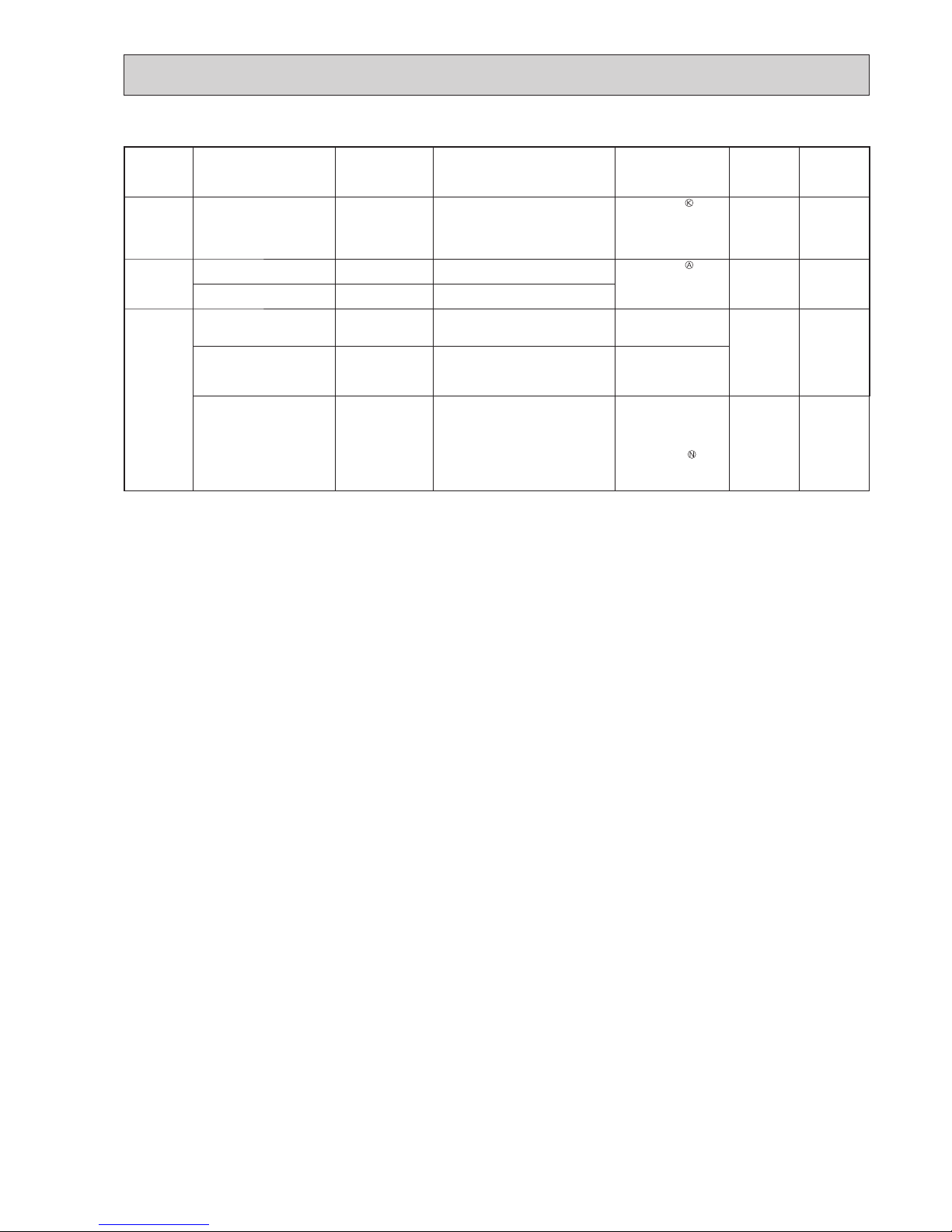
35
NOTE: Blinking patterns of this mode differ from the ones of TROUBLESHOOTING CHECK TABLE (12-3.).
Upper lamp
(Indoor unit)
Abnormal point
(Failure mode/protection)
LED indication
(Outdoor P.C. board)
Condition Remedy
Indoor/outdoor
unit failure
mode recall
function
Outdoor unit
failure mode
recall function
10-time fl ash
2.5 seconds
OFF
Discharge temperature
—
Temperature of discharge temperature
thermistor has been 50°C or less for
20 minutes.
•
Refer to 12-5.
"Check
of LEV".
•
Check refrigerant
circuit and refrigerant
amount.
—
○
11-time fl ash
2.5 seconds
OFF
Bus-bar voltage (DC) 8-time fl ash
2.5 seconds OFF
Bus-bar voltage of inverter cannot be
detected normally.
•
Refer to 12-5. "How
to check inverter/
compressor".
—
○
Each phase current of
compressor
9-time fl ash
2.5 seconds OFF
Each phase current of compressor
cannot be detected normally.
14-time fl ash
or more
2.5 seconds
OFF
Stop valve (Closed valve) 14-time fl ash
2.5 seconds OFF
Closed valve is detected by
compressor current.
•
Check stop valve.
○○
4-way valve/
Pipe temperature
16-time fl ash
2.5 seconds OFF
The 4-way valve does not work
properly.
The indoor coil thermistor detects an
abnormal temperature.
•
Check the 4-way
valve.
•
Replace the inverter
P.C. board.
Outdoor refrigerant system
abnormality
1-time fl ash
2.5 seconds OFF
A closed valve and air trapped in the
refrigerant circuit are detected based
on the temperature sensed by the
indoor and outdoor thermistors and the
current of the compressor.
•
Check for a gas leak
in a connecting piping
etc.
•
Check the stop valve.
•
Refer to 12-5.
“Check of outdoor
refrigerant circuit”.
○○
OBH789
Page 36

36
12-3. TROUBLESHOOTING CHECK TABLE
No. Symptom LED indication
Abnormal point/ Con-
dition
Condition Remedy
1
Outdoor unit
does not operate.
1-time fl ash every
2.5 seconds
Outdoor power system
Overcurrent protection cut-out operates 3 consecutive times
within 1 minute after the compressor gets started.
•
Reconnect connector of compressor.
•
Refer to 12-5.
"How to check
inverter/compressor".
•
Check stop valve.
2
Outdoor thermistors Discharge temperature thermistor, fi n temperature thermistor,
defrost thermistor, P.C. board temperature thermistor, outdoor
heat exchanger temperature thermistor or ambient temperature thermistor shorts or opens during compressor running.
•
Refer to 12-5.
"Check of outdoor
thermistors".
3
Outdoor control system
Nonvolatile memory data cannot be read properly.
(Upper lamp of OPERATION INDICATOR lamp on the indoor
unit lights up or fl ashes 7-time.)
•
Replace inverter P.C. board.
4
6-time fl ash
2.5 seconds OFF
Serial signal The communication fails between the indoor and outdoor unit
for 3 minutes.
•
Refer to 12-5.
"How to check
miswiring and serial signal error.
5
11-time fl ash
2.5 seconds OFF
Stop valve/
Closed valve
Closed valve is detected by compressor current.
•
Check stop valve.
6
14-time fl ash
2.5 seconds OFF
Outdoor unit
(Other abnormality)
Outdoor unit is defective.
•
Refer to 12-2.2. "Flow chart of the
detailed outdoor unit failure mode
recall function".
7
16-time fl ash
2.5 seconds OFF
4-way valve/
Pipe temperature
The 4-way valve does not work properly.
The indoor coil thermistor detects an abnormal temperature.
•
Refer to 12-5.
"Check of R.V.
coil".
•
Replace the inverter P.C. board.
8
17-time fl ash
2.5 seconds OFF
Outdoor refrigerant
system abnormality
A closed valve and air trapped in the refrigerant circuit are
detected based on the temperature sensed by the indoor and
outdoor thermistors and the current of the compressor.
•
Check for a gas leak in a
connecting piping etc.
•
Check the stop valve.
•
Refer to 12-5.
“Check of outdoor
refrigerant circuit”.
9
'Outdoor unit
stops and
restarts 3
minutes later'
is repeated.
2-time fl ash
2.5 seconds OFF
Overcurrent protection
Large current fl ows into power module (IC700).
•
Reconnect connector of compressor.
•
Refer to 12-5. "How to check
inverter/compressor".
•
Check stop valve.
10
3-time fl ash
2.5 seconds OFF
Discharge temperature overheat
protection
Temperature of discharge temperature thermistor exceeds
116°C, compressor stops. Compressor can restart if discharge
temperature thermistor reads 100°C or less 3 minutes later.
•
Check refrigerant circuit and refrigerant amount.
•
Refer to 12-5.
"Check of LEV".
11
4-time fl ash
2.5 seconds OFF
Fin temperature /
P.C. board temperature thermistor
overheat protection
Temperature of fi n temperature thermistor on the heat sink
exceeds 75 ~ 86°C or temperature of P.C. board temperature
thermistor on the inverter P.C. board exceeds 72 ~ 85°C.
•
Check around outdoor unit.
•
Check outdoor unit air passage.
•
Refer to 12-5.
"Check of outdoor
fan motor".
12
5-time fl ash
2.5 seconds OFF
High pressure protection
Indoor coil thermistor exceeds 70°C in HEAT mode. Defrost
thermistor exceeds 70°C in COOL mode.
•
Check refrigerant circuit and refrigerant amount.
•
Check stop valve.
13
8-time fl ash
2.5 seconds OFF
Compressor synchronous abnormality
The waveform of compressor current is distorted.
•
Reconnect connector of compressor.
•
Refer to 12-5. "How to check
inverter/compressor".
14
10-time fl ash
2.5 seconds OFF
Outdoor fan motor Outdoor fan has stopped 3 times in a row within 30 seconds
after outdoor fan start-up.
•
Refer to 12-5.
"Check of outdoor
fan motor.
•
Refer to 12-5.
"Check of inverter
P.C. board.
15
12-time fl ash
2.5 seconds OFF
Each phase current
of compressor
Each phase current of compressor cannot be detected normally.
•
Refer to 12-5.
"How to check
inverter/compressor".
16
13-time fl ash
2.5 seconds OFF
Bus-bar voltage
(DC)
Bus-bar voltage of inverter cannot be detected normally.
•
It occurs with following case.
Instantaneous power voltage drop.
(Short time power failure) (AP50)
•
Refer to 12-5.
"Check of power
supply". (AP50)
•
Refer to 12-5.
"How to check in-
verter/compressor".
17
Outdoor unit
operates.
1-time fl ash
2.5 seconds OFF
Frequency drop by
current protection
When the input current exceeds approximately 10A, compressor frequency lowers.
The unit is normal, but check the
following.
•
Check if indoor fi lters are clogged.
•
Check if refrigerant is short.
•
Check if indoor/outdoor unit air
circulation is short cycled.
18
3-time fl ash
2.5 seconds OFF
Frequency drop by
high pressure protection
Temperature of indoor coil thermistor exceeds 55°C in HEAT
mode, compressor frequency lowers.
19
Frequency drop by
defrosting in COOL
mode
Indoor coil thermistor reads 8°C or less in COOL mode, compressor frequency lowers.
4-time fl ash
2.5 seconds OFF
Frequency drop by
discharge temperature protection
Temperature of discharge temperature thermistor exceeds
111°C, compressor frequency lowers.
•
Check refrigerant circuit and refrigerant amount.
•
Refer to 12-5.
"Check of LEV".
•
Refer to 12-5.
"Check of outdoor
thermistors".
20
MUZ-
AP25/35/42
5-time fl ash
2.5 seconds OFF
Outside temperature
thermistor protection
When the outside temperature thermistor shorts or opens,
protective operation without that thermistor is performed.
•
Refer to 12-5.
Check of outdoor
thermistors.
OBH789
Page 37
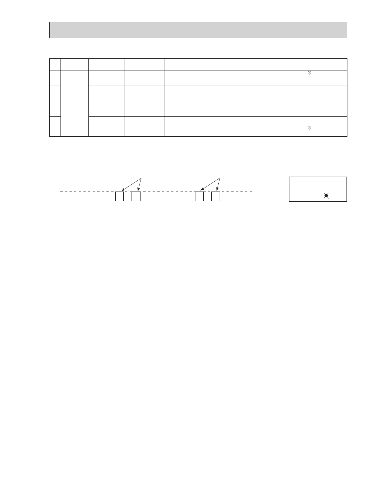
37
No. Symptom LED indication
Abnormal point/ Con-
dition
Condition Remedy
21
Outdoor unit
operates.
7-time fl ash
2.5 seconds OFF
Low discharge temperature protection
Temperature of discharge temperature thermistor has been
50°C or less for 20 minutes.
•
Refer to 12-5.
"Check of LEV".
•
Check refrigerant circuit and refrigerant amount.
22
8-time fl ash
2.5 seconds OFF
PAM protection
PAM: Pulse Amplitude Modulation
The overcurrent fl ows into PFC (Power factor correction:
IC820) or the bus-bar voltage reaches 394 V or more, PAM
stops and restarts.
This is not malfunction. PAM protection will be activated in the following cases:
1 Instantaneous power voltage
drop. (Short time power failure)
2 When the power supply voltage
is high.
23
9-time fl ash
2.5 seconds OFF
Inverter check mode The connector of compressor is disconnected, inverter check
mode starts.
•
Check if the connector of the compressor is correctly connected.
Refer to 12-5.
"How to check
inverter/compressor".
NOTE: 1. The location of LED is illustrated at the right fi gure. Refer to 12-6.1.
2. LED is lighted during normal operation.
The fl ashing frequency shows the number of times the LED blinks after every 2.5-second OFF.
(Example) When the fl ashing frequency is “2”.
ON
OFF
2.5-second OFF
2.5-second OFF
0.5-second ON
0.5-second ON
LED
Flashing →
Inverter P.C. board
OBH789
Page 38

38
12-4. TROUBLE CRITERION OF MAIN PARTS
Part name Check method and criterion Figure
Defrost thermistor (RT61)
Fin temperature
thermistor (RT64)
Ambient temperature
thermistor (RT65)
Outdoor heat exchanger
temperature thermistor
(RT68)
Measure the resistance with a tester.
Refer to 12-6. “Test point diagram and voltage”, 1. “Inverter P.C.
board”, for the chart of thermistor.
Discharge temperature
thermistor (RT62)
Measure the resistance with a tester. Before measurement, hold the
thermistor with your hands to warm it up.
Refer to 12-6. “Test point diagram and voltage”, 1. “Inverter P.C.
board”, for the chart of thermistor.
Compressor
Measure the resistance between terminals using a tester.
(Temperature: -10 ~ 40°C)
Normal (Ω)
MUZ-AP25/35VG(H) MUZ-AP42/50VG(H)
U-V
U-W
V-W
1.59 ~ 2.16 0.82 ~ 1.11
W
U
V
WHT
RED BLK
Outdoor fan motor
Measure the resistance between lead wires using a tester.
(Temperature: -10 ~ 40°C)
Color of lead wire
Normal (Ω)
MUZ-AP25/35/42VG(H) MUZ-AP50VG(H)
RED – BLK
BLK – WHT
WHT – RED
32 ~ 43 15 ~ 20
W
U
V
WHT
RED BLK
R. V. coil (21S4)
Measure the resistance using a tester. (Temperature: -10 ~ 40°C)
Normal (kΩ)
1.41 ~ 2.00
Expansion valve coil
(LEV)
Measure the resistance using a tester. (Temperature: -10 ~ 40°C)
Color of lead wire Normal (Ω)
RED – ORN
37 ~ 54
RED – WHT
RED – BLU
RED – YLW
RED
(+12V)
YLW
BLU
WHT
ORN
LEV
Defrost heater
MUZ-AP•VGH
Normal (Ω)
MUZ-AP25/35/42VGH MUZ-AP50VGH
802 ~ 980 370 ~ 428
OBH789
Page 39

39
12-5. TROUBLESHOOTING FLOW
A How to check inverter/compressor
Refer to 12-5. “Check of compressor
operation time”.
Does the compressor operate continuously?
Refer to 12-5. “Check of compressor start failure”.
OK
No
Yes
Refer to 12-5. “Check of compressor
winding”.
Is the compressor normal?
Replace the compressor.
No
Yes
B Check of open phase
C Check of compressor
● With the connector between the compressor and the power module (IC700) disconnected, activate the inverter and check if
the inverter is normal by measuring the voltage balance between the terminals.
Output voltage is 50 - 130 V. (The voltage may differ according to the tester.)
<< Operation method>>
Start cooling or heating operation by pressing EMERGENCY OPERATION switch on the indoor unit. (TEST RUN OPERA-
TION: Refer to 9-3.)
<<Measurement point>>
At 3 points
BLK (U)-WHT (V)
BLK (U)-RED (W)
WHT(V)-RED (W)
NOTE: 1. Output voltage varies according to power supply voltage.
2. Measure the voltage by analog type tester.
3. During this check, LED of the inverter P.C. board fl ashes 9 times. (Refer to 12-6.1.)
Measure AC voltage between the lead wires at 3 points.
Are the voltages balanced?
Disconnect the connector between the compressor
and the power module (IC700).
Replace the inverter P.C. board.
Check the voltage between terminals.
Check the compressor.
See 12-5. “Check of compressor”.
No
Yes
See 12-5. “Check of open phase”.
OBH789
Page 40

40
F Check of compressor start failure
D Check of compressor winding
E Check of compressor operation time
● Disconnect the connector between the compressor and the power module (IC700), and measure the resistance between the
compressor terminals.
<<Measurement point>>
At 3 points
BLK-WHT
BLK-RED
WHT-RED
<<Judgement>>
Refer to 12-4.
0 [Ω] ················Abnormal [short]
Infinite [Ω] ·······Abnormal [open]
NOTE: Be sure to zero the ohmmeter before measurement.
Measure the resistance between the lead wires at 3 points.
1
Heat the compressor with
a drier for about 20 minutes.
Do not recover refrigerant
gas while heating.
Heating part
● Connect the compressor and activate the inverter. Then measure
the time until the inverter stops due to overcurrent.
<<Operation method>>
Start heating or cooling operation by pressing EMERGENCY
OPERATION switch on the indoor unit. (TEST RUN OPERATION:
Refer to 9-3.)
<<Measurement>>
Measure the time from the start of compressor to the stop of
compressor due to overcurrent.
Compressor starts
Abnormal
(IC700 failure)
(Compressor winding short)
Abnormal
(Compressor lock out)
(Starting defect)
Abnormal
(Poor contact)
(Inverter P.C. board defect)
(Disconnected connector)
Abnormal
(Refrigerant circuit defect)
(Closed valve)
Normal
0 second
1 second
2 seconds
10 seconds
10 minutes
<<Judgement>>
After the compressor is heated with a drier,
does the compressor start?
1
Replace the compressor.
Compressor start failure. Activate pre-heat control.
(Refer to 11-2. "PRE-HEAT CONTROL SETTING")
No
Yes
Does the compressor run for 10 seconds or
more after it starts?
Check the refrigerant circuit.
Check the stop valve.
Yes
No
Confi rm that ~ is normal.
•Electrical circuit check
. Contact of the compressor connector
. Output voltage of inverter P.C. board and balance of them (See 12-5. )
. Direct current voltage between DB61(+) and (-) on the inverter P.C. board
. Voltage between outdoor terminal block S1-S2
OBH789
Page 41

41
G Check of outdoor thermistors
Replace the thermistor except RT64.
When RT64 is abnormal, replace the inverter P.C.
board.
Replace the inverter P.C. board.
No
No
Is the resistance of thermistor normal?
(Refer to 12-6.1.)
Reconnect the connector of thermistor.
Turn ON the power supply and press EMERGENCY OPERATION switch.
Does the unit operate for 10 minutes or more
without showing thermistor abnormality?
OK (Cause is poor contact.)
Yes
Yes
Disconnect the connector of thermistor in the inverter P.C. board (see
below table), and measure the resistance of thermistor.
Thermistor Symbol Connector, Pin No. Board
Defrost RT61 Between CN641 pin1 and pin2
Inverter P.C. board
Discharge temperature RT62 Between CN641 pin3 and pin4
Fin temperature RT64 Between CN642 pin1 and pin2
Ambient temperature RT65 Between CN643 pin1 and pin2
Outdoor heat exchanger temperature RT68 Between CN644 pin1 and pin3
OBH789
Page 42

42
H Check of R.V. coil
First of all, measure the resistance of R.V. coil to check if the coil is defective. Refer to 12-4.
In case CN721 is disconnected or R.V. coil is open, voltage is generated between the terminal pins of the connector
although no signal is being transmitted to R.V. coil.
Check if CN721 is connected.
Is there 230 V AC between CN721 and
on the inverter P.C. board 3 minutes
after the power supply is turned ON?
No
Yes
Replace the inverter
P.C. board.
Replace the 4-way valve.
Unit operates COOL mode even if it is set to HEAT mode.
Is there 230 V AC between CN721 and
on the inverter P.C. board 3 minutes
after the power supply is turned ON?
Yes
No
Replace the inverter
P.C. board.
Replace the 4-way valve.
Unit operates HEAT mode even if it is set to COOL mode.
Disconnect connector between the
compressor and the IGBT module
(IC700).
Turn ON the power supply and press
EMERGENCY OPERATION switch
twice (HEAT mode).
Disconnect connector between the
compressor and the IGBT module
(IC700).
Turn ON the power supply and
press EMERGENCY OPERATION
switch once (COOL mode).
OBH789
Page 43

43
I Check of outdoor fan motor
Is the resistance between each terminal of outdoor fan motor normal?
(Refer to 12-4.)
Disconnect CN932 from the inverter P.C. board, and turn on the
power supply.
Rotate the outdoor fan motor manually and measure the voltage
of CN931.
Between 1(+) and 5(-)
Between 2(+) and 5(-)
Between 3(+) and 5(-)
Does the voltage between each terminal become 5 and 0 V
DC repeatedly?
Does the outdoor fan motor rotate smoothly?
Replace the outdoor fan motor.
Replace the inverter P.C. board.
Yes
Yes
No
(Fixed to either 5 or 0 V DC)
No
No
Yes
Disconnect the connectors CN931
and CN932 from the inverter P.C.
board.
Check the connection between the
connector CN931 and CN932.
OBH789
Page 44

44
J Check of power supply
Is there voltage 230 V AC
between the indoor terminal
block S1 and S2?
No
Yes
Replace the indoor
electronic control P.C.
board.
Rectify indoor/outdoor
connecting wire.
Yes
If lights up, OK.
If fl ashes, refer to 12-3.
Does the upper lamp of
OPERATION INDICATOR lamp on
the indoor unit light up?
Does LED on the inverter P.C.
board light up or fl ash?
(Refer to 12-6.1.)
No
Replace the inverter
P.C. board.
Is there bus-bar voltage 260 - 370 V
DC between DB61 (+) and DB61 (–)
on the inverter P.C. board? (Refer to
12-6.1.)
No
Check the electric parts in main circuit.
Yes
Yes
No
Disconnect the connector between the
compressor and the
power module
(IC700). Turn ON power supply and
press EMERGENCY OPERATION
switch.
Inverter P.C. board
(Solder side)
DB61
260 - 370 V DC
OBH789
Page 45
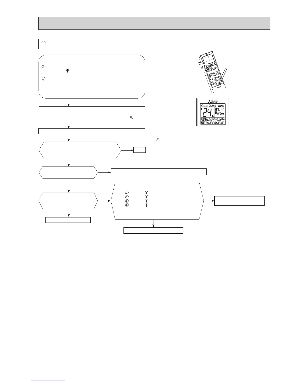
45
Press STOP/OPERATE (OFF/ON) button of the remote
controller (the set temperature is displayed) with the
remote controller headed towards the indoor unit. 1
Expansion valve operates in full-opening direction.
OK
NOTE: After check of LEV, do the undermentioned operations.
1. Turn OFF the power supply and turn it ON again.
2. Press RESET button on the remote controller.
1. Regardless of normal or abnormal condition, a short beep
is emitted once the signal is received.
Measure each voltage between connector
pins of CN724 on the inverter P.C. board.
1. Pin (-) — Pin (+)
2. Pin (-) — Pin (+)
3. Pin (-) — Pin (+)
4. Pin (-) — Pin (+)
Is there about 3 - 5 V AC between each?
NOTE: Measure the voltage by an analog
tester.
Properly fi x the LEV coil to the expansion valve.
Replace the inverter P.C.
board.
Replace the LEV coil.
Replace the expansion valve.
Is LEV coil properly fi xed to
the expansion valve?
Does the resistance of LEV
coil have the characteristics?
(Refer to 12-4.)
Do you hear the expansion valve "click,
click·······"?
Do you feel the expansion valve vibrate
when touching it ?
Turn ON the power supply.
<Preparation of the remote controller>
While pressing both OPERATION SELECT button
and TEMP button on the remote controller at the
same time, press RESET button.
First, release RESET button.
Hold down the other 2 buttons for another 3 seconds.
Make sure that the indicators on the LCD screen
shown in the right fi gure are all displayed. Then re-
lease the buttons.
Yes
No
No
Yes
No
Yes
No
Yes
K Check of LEV (Expansion valve)
WEEKLY TIMER
MSZ-AP·VG(K)
OBH789
Page 46

46
Check the outdoor fan motor.
(Refer to 12-5. .)
Is the fuse (F901) blown on the inverter P.C. board?
Check the connection of the connectors
(CN931, CN932) of the outdoor fan motor.
If the connection is poor, make it correct.
Operate the outdoor unit by starting
EMERGENCY OPERATION.
Check the LED indication on the inverter P.C. board.
Does the LED fl ash 10 times?
Replace the inverter P.C. board.
Check the corresponding parts
following LED indication.
(Refer to 12-3.)
Yes
No
Yes
(10-time fl ash)
No
L Check of inverter P.C. board
OBH789
Page 47

47
M How to check miswiring and serial signal error
• Turn OFF inverter-controlled lighting equipment.
• Turn OFF the power supply and then turn ON again.
• Press EMERGENCY OPERATION switch.
A
Is serial signal
error indicated 6
minutes later?
B
Yes
• Reinstall either the unit or the light
away from each other.
• Attach a fi lter on remote control
receiving section of the indoor unit.
No
Turn the main power supply
OFF.
Is there rated voltage in the power supply?
Yes
No
Check for incorrect indoor-outdoor connecting wiring.
Check the power supply.
A
Is there rated voltage between outdoor terminal block S1 and S2?
Yes
Check for miswiring, broken wires, and loose
wire connection between the main power
supply and outdoor terminal block S1 and
between the main power supply and outdoor
terminal block S2.
Wait for 2 or more minutes after the main power supply is turned on.
Touch S2 and S3 with tester probes and start the emergency operation.
When the emergency operation starts, does the rated voltage occur for 2
seconds between indoor terminal block S2 and S3?
Yes
No
Does the upper lamp of OPERATION INDICATOR lamp on the
indoor unit blink continuously
6 minutes after the emergency
operation starts?
No
Does the outdoor LED light up?
Replace the
indoor electronic
control P.C. board.
Yes
Does the outdoor LED blink 6
times?
Yes
Confi rm that the thermostat is OFF
and wiring is not loose.
No
Does DC (6V or more) occur
between indoor terminal block S2
and S3?
Yes
Replace the outdoor inverter P.C. board. 1
No
Replace the indoor electronic control P.C. board.
1
1.
Electric charge may remain immediately
after the main power supply is turned OFF.
Perform the procedure after 3 minutes.
Replace the outdoor inverter P.C. board. 1
Yes
Turn the main power supply ON.
B
No
No
Was the indoor unit ever connected to
the Multi (MXZ) series and operated
(turned on)?
The connection information to the Multi series is stored
in the indoor unit. Refer to “Deleting the memorized
abnormal condition” described in 12-2.1 to clear the error
history. When the error history is being cleared, the connection information also will be initialized. The indoor unit
will be compatible with a low-standby-power model after
initialization.
OK
Yes
No
OBH789
Page 48

48
N Check of the outdoor refrigerant circuit
Has the operation stopped
during pump down?
Was the operation started with
the stop valve closed, and was
it opened during operation?
No
Yes
The operation has stopped to prevent the diesel explosion caused by
air trapped in the refrigerant circuit.
Close the stop valve, and disconnect
the power plug or turn the breaker
OFF.
The unit occasionally stops when the
stop valve is opened or closed during
operation. Open the stop valve and
start the cooling operation again.
Yes
No
The refrigerant gas amount may be
60% or less than the normal amount.
Identify where the gas is leaking from,
and fi x the leak.
CAUTION : Do not start the operation again to prevent hazards.
OBH789
Page 49

49
O Electromagnetic noise enters into TV sets or radios
Yes
Is the unit earthed?
No
Earth the unit.
Yes
Is the distance between the antennas
and the indoor unit within 3 m, or is the
distance between the antennas and the
outdoor unit within 3 m?
No
Extend the distance between the antennas and
the indoor unit, and/or the antennas and the
outdoor unit.
Is the distance between the TV sets or
radios and the indoor unit within 1 m, or
is the distance between the TV sets or
radios and the outdoor unit within 3 m?
Yes
Extend the distance between the TV sets and/
or radios and the indoor unit, or the TV sets or
radios and the outdoor unit.
Are the antennas damaged?
Is the coaxial cable damaged?
Is there any poor contact in the antenna wiring?
Yes
No
No
Replace or repair the antenna.
Replace or repair the coaxial cable.
Is the indoor/outdoor connecting wire
of the air conditioner and the wiring of
the antennas close?
Yes
Extend the distance between the indoor/outdoor
connecting wire of the air conditioner and the wiring of the antennas.
No
Even if all of the above conditions are fulfi lled, the electromagnetic noise may enter, depending on the electric fi eld strength
or the installation condition (combination of specifi c conditions such as antennas or wiring).
Check the following before asking for service.
1. Devices affected by the electromagnetic noise
TV sets, radios (FM/AM broadcast, shortwave)
2. Channel, frequency, broadcast station affected by the electromagnetic noise
3. Channel, frequency, broadcast station unaffected by the electromagnetic noise
4. Layout of:
indoor/outdoor unit of the air conditioner, indoor/outdoor wiring, earth wire, antennas, wiring from antennas, receiver
5. Electric fi eld intensity of the broadcast station affected by the electromagnetic noise
6. Presence or absence of amplifi er such as booster
7. Operation condition of air conditioner when the electromagnetic noise enters in
1) Turn OFF the power supply once, and then turn ON the power supply. In this situation, check for the electromagnetic
noise.
2) Within 3 minutes after turning ON the power supply, press STOP/OPERATE (OFF/ON) button on the remote controller
for power ON, and check for the electromagnetic noise.
3) After a short time (3 minutes later after turning ON), the outdoor unit starts running. During operation, check for the
electromagnetic noise.
4) Press STOP/OPERATE (OFF/ON) button on the remote controller for power OFF, when the outdoor unit stops but the
indoor/outdoor communication still runs on. In this situation, check for the electromagnetic noise.
OBH789
Page 50

50
-20 -10 0 10 20 30 40
0
10
20
30
40
50
60
70
80
90
100
Temperature( )
Defrost thermistor(RT61)
Ambient temperature thermistor(RT65)
Outdoor heat exchanger temperature thermistor(RT68)
0 1020304050607080
0
20
40
60
80
100
120
140
160
180
200
Temperature( )
Fin temperature thermistor(RT64)
Resistance(k )
Resistance(k )
Temperature (°C)
Discharge temperature thermistor (RT62)
5HVLVWDQFHN
0
100
200
300
400
500
600
700
800
0 102030405060708090100110120
1. Inverter P.C. board
12-6. TEST POINT DIAGRAM AND VOLTAGE
Fin temperature
thermistor/RT64
(CN642)
Ambient temperature
thermistor/RT65
(CN643)
Discharge temperature
thermistor/RT62
(CN641)
Defrost thermistor
/RT61(CN641)
DB61
260 - 370 V DC
Front side of unit
230 V AC
Output to
drive
compressor
(LDU,
LDV,
LDW)
(+)
(-)
Fuse (F701)
T3.15AL250V
R.V.coil
(CN721)
230 V AC
Jumper wire for
changing defrost
setting (JS)
Signal of outdoor
fan motor (CN931)
230 V AC
Outdoor heat exchanger
temperature thermistor
/RT68 (CN644)
Jumper wire
for pre-heat
control setting
(JK)
Fuse (F801)
T3.15AL250V
Back side of unit
LEV (CN724)
Output to
drive outdoor
fan motor
(CN932)
LED
MUZ-AP25VG MUZ-AP35VG MUZ-AP42VG MUZ-AP50VG
MUZ-AP25VGH MUZ-AP35VGH MUZ-AP42VGH MUZ-AP50VGH
Defrost heater
(CN722)
(MUZ-AP•VGH)
Fuse (F62)
15 A 250 V
Fuse (F901)
T3.15AL250V
Smoothing
capacitor
(C63)
Smoothing
capacitor
(C62)
Smoothing
capacitor (C61)
(MUZ-AP42/50)
Fuse (F61)
25 A 250V
OBH789
Page 51

13-1. MUZ-AP25VG MUZ-AP35VG MUZ-AP42VG
MUZ-AP25VGH MUZ-AP35VGH MUZ-AP42VGH
NOTE: Turn OFF the power supply before disassembly.
Photos: MUZ-AP42VGH
OPERATING PROCEDURE PHOTOS
1. Removing the cabinet
(1) Remove the screw fixing the service panel.
(2) Pull down the service panel and remove it.
(3) Disconnect the power supply cord and indoor/outdoor
connecting wire.
(4) Remove the screws fixing the top panel.
(5) Remove the top panel.
(6) Remove the screws fixing the cabinet.
(7) Remove the cabinet.
(8) Remove the screws fixing the back panel.
(9) Remove the back panel.
Photo 1
Photo 2
51
(1) Slide the sleeve and check if there is a locking lever or not. (2) The terminal with this connector shown below has the
locking mechanism.
Slide the sleeve.
Pull the terminal while
pushing the locking
lever.
Hold the sleeve, and
pull out the terminal
slowly.
Connector
Sleeve
Locking lever
Back
panel
Service
panel
Screws of the
cabinet
Screws of the
top panel
<Detaching method of the terminal with locking mechanism >
The terminal which has the locking mechanism can be detached as shown below.
There are following 2 types of the terminal with locking mechanism.
The terminal without locking mechanism can be detached by pulling it out.
Check the shape of the terminal before detaching.
DISASSEMBLY INSTRUCTIONS
13
Screw of the
cabinet
Screws
of the
back
panel
Screws of
the terminal block
support and the
back panel
Screws of the
service panel
Direction to
remove
Hooks
Screws of the
top panel
Screws of the
cabinet
OBH789
Page 52

52
OPERATING PROCEDURE
PHOTOS
2. Removing the inverter assembly, inverter P.C. board
(1) Remove the cabinet and panels. (Refer to section 1.)
(2) Disconnect the lead wire to the reactor and the following con-
nectors:
<Inverter P.C. board>
CN721 (R.V. coil)
CN722 (Defrost heater)(MUZ-AP•VGH)
CN931, CN932 (Fan motor)
CN641 (Defrost thermistor and discharge temperature ther-
mistor)
CN643 (Ambient temperature thermistor)
CN644 (Outdoor heat exchanger temperature thermistor)
CN724 (LEV)
(3) Remove the compressor connector (CN61).
(4) Remove the screws fixing the heat sink support and the sep-
arator.
(5) Remove the fixing screws of the terminal block support and
the back panel.
(6) Remove the inverter assembly.
(7) Remove the screw of the earth wire and screw of the termi-
nal block support.
(8) Remove the heat sink support from the P.C. board support.
(9) Remove the screw of the inverter P.C. board and remove the
inverter P.C. board from the P.C. board support.
Photo 3
Photo 4 (Inverter assembly)
Photo 5
3. Removing R.V. coil
(1) Remove the cabinet and panels. (Refer to section 1.)
(2) Disconnect the following connectors:
<Inverter P.C. board>
CN721 (R.V. coil)
(3) Remove the R.V. coil.
4. Removing the discharge temperature thermistor,
defrost thermistor, outdoor heat exchanger temperature thermistor and ambient temperature thermistor
(1) Remove the cabinet and panels. (Refer to section 1.)
(2) Disconnect the lead wire to the reactor and the following con-
nectors:
<Inverter P.C. board>
CN641 (Defrost thermistor and discharge temperature ther-
mistor)
CN643 (Ambient temperature thermistor)
CN644 (Outdoor heat exchanger temperature thermistor)
(3) Pull out the discharge temperature thermistor from its holder.
(4) Pull out the defrost thermistor from its holder. (Photo 6)
(5) Pull out the outdoor heat exchanger temperature thermistor
from its holder. (Photo 6)
(6) Pull out the ambient temperature thermistor from its holder.
Discharge temperature thermistor
Screw of the
R.V. coil
Screws of the heat sink
support and the separator
Screws of the terminal block
support and the back panel
Heat sink
Screw of the
earth wire
Screw of the
Terminal block
support
Screw of the
inverter P.C. board
Heat sink support
P.C. board
support
Terminal
block
support
OBH789
Page 53

53
OPERATING PROCEDURE
PHOTOS
5. Removing outdoor fan motor
(1) Remove the cabinet and panels. (Refer to section 1.)
(2) Disconnect the following connectors:
<Inverter P.C. board>
CN931, CN932 (Fan motor)
(3) Remove the propeller fan nut.
(4) Remove the propeller fan.
(5) Remove the screws fixing the fan motor.
(6) Remove the fan motor.
Photo 6
NOTE: MUZ-AP25/35VG/H are different in the installa-
tion position of thermistors.
Photo 7
6. Removing the compressor and 4-way valve
(1) Remove the cabinet and panels. (Refer to section 1.)
(2) Remove the inverter assembly. (Refer to section 2.)
(3) Recover gas from the refrigerant circuit.
NOTE: Recover gas from the pipes until the pressure gauge
shows 0 kg/cm2 (0 MPa).
(4) Detach the brazed part of the suction and the discharge pipe
connected with compressor.
(5) Remove the nuts of compressor legs.
(6) Remove the compressor.
(7) Detach the brazed part of pipes connected with 4-way valve.
7. Removing the LEV assembly
(1) Detaching the brazed part of pipes connected with LEV
valve.
Photo 8
Defrost thermistor
Outdoor heat
exchanger temperature thermistor
Brazed parts of 4-way valve
Ambient temperature
thermistor
Brazed parts of LEV valve
Propeller fan nut
Screws of the outdoor fan motor
Propeller fan
OBH789
Page 54

54
13-2. MUZ-AP50VG MUZ-AP50VGH
NOTE: Turn OFF the power supply before disassembly.
OPERATING PROCEDURE
PHOTOS
1. Removing the cabinet
(1) Remove the screws of the service panel.
(2) Remove the screws of the top panel.
(3) Remove the screw of the valve cover.
(4) Remove the service panel.
(5) Remove the top panel.
(6) Remove the valve cover.
(7) Disconnect the power supply and indoor/outdoor connect-
ing wire.
(8) Remove the screws of the cabinet.
(9) Remove the cabinet.
(10)
Remove the screws of the back panel.
(11)
Remove the back panel.
Photo 2
Photo 1
Screws of
the cabinet
Screws of the top panel
Screws of
the cabinet
Screws of the top panel
Screw of the back panel
Screws of
the service panel
Screw of
the valve cover
Screws of
the cabinet
Screws of
the back panel
OBH789
Page 55

55
OPERATING PROCEDURE PHOTOS
2. Removing the inverter assembly and inverter P.C.
board
(1) Remove the cabinet and panels. (Refer to section 1.)
(2) Disconnect the lead wire to the reactor and the following con-
nectors:
<Inverter P.C. board>
CN721 (R.V. coil)
CN722 (Defrost heater)(MUZ-AP50VGH)
CN931, CN932 (Fan motor)
CN641 (Defrost thermistor and discharge temperature ther-
mistor)
CN643 (Ambient temperature thermistor)
CN644 (Outdoor heat exchanger temperature thermistor)
CN724 (LEV)
(3) Remove the compressor connector (CN61).
(4) Remove the screws fixing the heat sink support and the sep-
arator.
(5)
Remove the fixing screw of the P.B. support and the separator.
(6) Remove the fixing screws of the terminal block support and
the back panel.
(7) Remove the inverter assembly.
(8) Remove the heat sink support from the P.C. board support.
(9) Remove the screw of the inverter P.C. board and remove the
inverter P.C. board from the P.C. board support.
*
Connection procedure when attaching the inverter P.C.
board (Photo 4)
1. Connect the lead wires of the heat exchanger temperature
thermistor, the defrost thermistor and discharge temperature thermistor to the connector on the inverter P.C. board.
Pull the lead wires toward you and put them on the right
hook on the P.C. board support.
2. Connect the lead wires of the LEV to the connector on the
inverter P.C. board. Pull the lead wires toward you and put
them on the right hook on the P.C. board support.
3. Connect the lead wires of the ambient temperature thermistor to the connector on the inverter P.C. board. Pull
the lead wires toward you and put them on the left hook
on the P.C. board support so that the fan motor lead wires
are bundled up as shown in Photo 4.
Photo 3
Photo 4
Photo 5 (Inverter assembly)
Screw of the heat sink
support and the separator
Screws of
the terminal block
support and
the back panel
Screw of the P.B. support
and the separator
Heat sink
Screws of
the earth wire
Screw of the inverter P.C. board
Heat sink support
P.C. board support
Inverter P.C. board
Lead wires of
the LEV
Lead wires of
the heat exchanger
temperature and
discharge temperature
thermistor
Inverter P.C. board support
Lead wires of
the ambient
temperature
thermistor
OBH789
Page 56

56
OPERATING PROCEDURE
PHOTOS
3. Removing R. V. coil
(1) Remove the cabinet and panels. (Refer to section 1.)
(2) Disconnect the following connectors:
<Inverter P.C. board>
CN721 (R.V. coil)
(3) Remove the R.V. coil.
Photo 6
Photo 7
4. Removing the discharge temperature thermistor,
defrost thermistor, outdoor heat exchanger temperature thermistor and ambient temperature thermistor
(1) Remove the cabinet and panels. (Refer to section 1.)
(2) Disconnect the lead wire to the reactor and the following con-
nectors:
<Inverter P.C. board>
CN641 (Defrost thermistor and discharge temperature ther-
mistor)
CN643 (Ambient temperature thermistor)
CN644 (Outdoor heat exchanger temperature thermistor)
(3) Pull out the discharge temperature thermistor from its holder.
(4) Pull out the defrost thermistor from its holder.
(5) Pull out the outdoor heat exchanger temperature thermistor
from its holder.
(6) Pull out the ambient temperature thermistor from its holder.
5. Removing outdoor fan motor
(1) Remove the cabinet and panels. (Refer to section 1.)
(2) Disconnect the following connectors:
<Inverter P.C. board>
CN931, CN932 (Fan motor)
(3) Remove the propeller fan nut.
(4) Remove the propeller fan.
(5) Remove the screws fixing the fan motor.
(6) Remove the fan motor.
Photo 8
Discharge temperature thermistor
Screw of the R.V. coil
Defrost thermistor
Outdoor heat
exchanger temperature thermistor
Ambient temperature
thermistor
Screws of the outdoor fan motor
Propeller fan
Propeller fan nut
OBH789
Page 57

57
OPERATING PROCEDURE
PHOTOS
6. Removing the compressor and 4-way valve
(1) Remove the cabinet and panels. (Refer to section 1.)
(2) Remove the inverter assembly. (Refer to section 2.)
(3) Recover gas from the refrigerant circuit.
NOTE: Recover gas from the pipes until the pressure gauge
shows 0 kg/cm2 (0 MPa).
(4) Detach the brazed part of the suction and the discharge pipe
connected with compressor.
(5) Remove the compressor nuts.
(6) Remove the compressor.
(7) Detach the brazed part of pipes connected with 4-way valve.
Photo 9
Brazed parts of 4-way valve
Suction pipe
brazed part
Discharge pipe
brazed part
OBH789
Page 58

HEAD OFFICE: TOKYO BUILDING, 2-7-3, MARUNOUCHI, CHIYODA-KU, TOKYO 100-8310, JAPAN
© Copyright 2017 MITSUBISHI ELECTRIC CORPORATION
Published: Dec. 2017. No. OBH789
Made in Japan Specifications are subject to change without notice.
 Loading...