

HFC
utilized
R410A
SPLIT-TYPE, HEAT PUMP AIR CONDITIONERS
OUTDOOR UNIT
SERVICE MANUAL
Wireless type
Models
Revision A:
● MUH-GA20VB- and MUH-GA25VB -
have been added.
Please void OB387.
No. OB387
REVISED EDITION-A
E2E2
MUH-GA20VBMUH-GA20VBMUH-GA25VBMUH-GA25VBMUH-GA35VB-
MUH-GA20VB
MUH-GA25VB
MUH-GA35VB
E1
E2
E1
E2
E1
Indoor unit service manual
MSC-GA• VB Series (OB385)
MSC-CA• VB Series (OB393)
MSC-CB• VB Series (OB439)
CONTENTS
1. TECHNICAL CHANGES ····································2
2. PART NAMES AND FUNCTIONS······················3
3. SPECIFICATION·················································3
4. NOISE CRITERIA CURVES·······························5
5. OUTLINES AND DIMENSIONS·························6
6. WIRING DIAGRAM ············································7
7. REFRIGERANT SYSTEM DIAGRAM················8
8. PERFORMANCE CURVES································9
9. ACTUA TOR CONTROL····································19
10. SERVICE FUNCTIONS·····································20
11. TROUBLESHOOTING ······································20
12. DISASSEMBLY INSTRUCTIONS·····················27
13. PARTS LIST······················································30
14. RoHS PARTS LIST···········································32
NOTE:
• This service manual describes technical data of outdoor units.
• RoHS compliant products have <G> mark on the spec name plate.
For servicing of RoHS compliant products, refer to the RoHS Parts List.

Revision A:
• MUH-GA20VB- and MUH-GA25VB- have been added.
E2E2
1
MUH-A07YV- ➔MUH-GA20VB-
1. Indication of capacity has been changed. (BTU base ➔ kw)
2. Dimension of outdoor unit has been changed. (W780mm x H540mm x D255mm ➔ W800mm x H550mm x D285mm)
3. Stop valve cover has been added.
4. Outdoor fan motor has been changed. (RC6V20-AB ➔ RA6V21-AD)
5. Outdoor fan motor capacitor has been changed.
6. Compressor capacitor has been changed.
7. Outdoor heat exchanger has been changed. (L-BEND ➔ FLAT)
MUH-A09YV- ➔MUH-GA25VB-
1. Indication of capacity has been changed. (BTU base ➔ kw)
2. Dimension of outdoor unit has been changed. (W780mm x H540mm x D255mm ➔ W800mm x H550mm x D285mm)
3. Stop valve cover has been added.
4. Outdoor fan motor has been changed. (RA6V33-FB ➔ RA6V33-KB)
5. Outdoor fan motor capacitor has been changed.
6. Compressor capacitor has been changed.
7. Outdoor heat exchanger has been changed. (2 Row ➔ 1 Row)
MUH-A12YV- ➔MUH-GA35VB-
1. Indication of capacity has been changed. (BTU base ➔ kw)
2. Dimension of outdoor unit has been changed. (W780mm x H540mm x D255mm ➔ W800mm x H550mm x D285mm)
3. Stop valve cover has been added.
4. Outdoor fan motor has been changed. (RA6V33-FB ➔ RA6V33-KB)
5. Outdoor fan motor capacitor has been changed.
6. Compressor capacitor has been changed.
7. Size of stop valve (gas) has been changed.([12.7 ➔ [9.52)
8. Outdoor heat exchanger has been changed. (2 Row ➔ 1 Row)
TECHNICAL CHANGES
E1E1
E1E1
E1E1
MUH-GA20VB- ➔MUH-GA20VB-
1. Compressor has been changed. (BN092VHST ➔ KN092VDMHC)
2. Compressor capacitor has been changed.
3. Capillary tube has been changed.
4. Refrigerant filling capacity has been changed.
5. Deicer P.C. board has been changed.
MUH-GA25VB- ➔MUH-GA25VB-
1. Compressor has been changed. (RN104VHSHT ➔ KN104VTMHC)
2. Compressor capacitor has been changed.
3. Capillary tube has been changed.
4. Refrigerant filling capacity has been changed.
5. Deicer P.C. board has been changed.
E2E1
E2E1
2
2
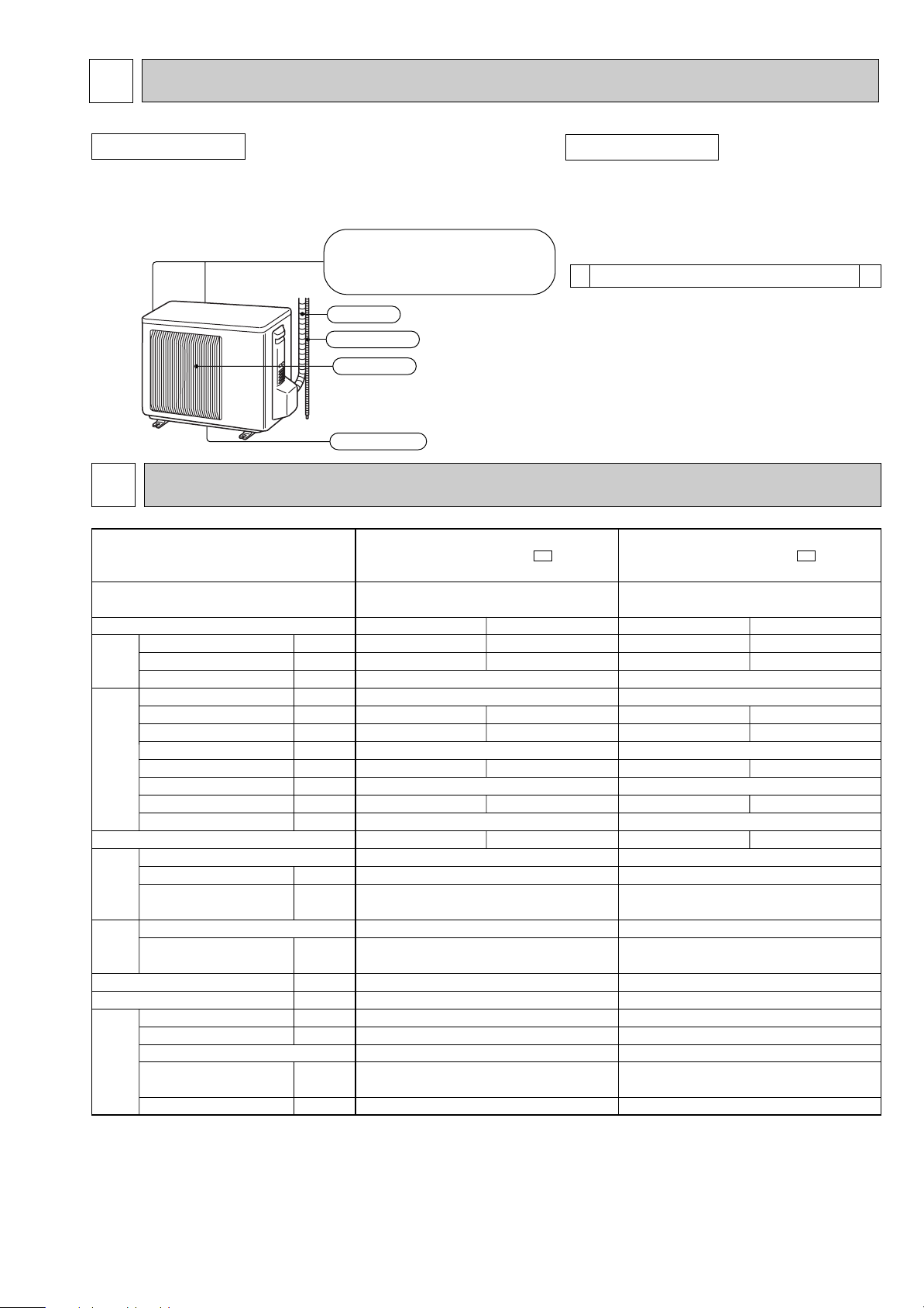
( )
Air inlet
Air outlet
Drain outlet
Piping
Drain hose
back : MUH-GA20VB
back and side : MUH-GA25VB
MUH-GA35VB
Drain socket
1
<Outdoor unit: MUH type>
1
Capacity
Dehumidification
Outdoor air flow
Power outlet
Running current
Power input
Auxiliary heater
Power factor
Starting current
Compressor motor current
Fan motor current
Model
Output
Winding
resistance (at 20:)
Model
Winding
resistance (at 20:)
Dimensions WOHOD
Weight
Sound level
Fan speed
Fan speed regulator
Refrigerant filling
capacity (R410A)
Refrigeration oil (Model)
kW
R/h
K /h
A
A
W
A(kW)
%
A
A
A
W
"
"
mm
kg
dB
rpm
kg
cc
MUH-GA20VB -
E1
Single phase
230V,50Hz
1,800
10
—
21
0.25
RN092VHSHT
600
C-R 3.87
C-S 6.14
RA6V21-AD
WHT-BLK 366
BLK-RED 274
800o550o285
32
47
745
1
0.65
350 (NEO22)
Cooling
2.3
0.9
3.00
680
99
2.76
3.22
Heating
2.5
—
2.86
655
100
2.62
3.62
Compressor
Electrical
data
Fan
motor
Special
remarks
Capacity
Coefficient of performance (C.O.P)
Outdoor unit power supply
Function
Outdoor model
MUH-GA20VB -
E2
Single phase
230V,50Hz
1,800
10
—
15.5
0.25
KN092VDMHC
650
C-R 3.62
C-S 5.40
RA6V21-AD
WHT-BLK 366
BLK-RED 274
800o550o285
29
47
745
1
0.60
350 (NEO22)
Cooling
2.3
0.9
3.00
680
99
2.76
3.22
Heating
2.5
—
2.86
655
100
2.62
3.62
PART NAMES AND FUNCTIONS
OUTDOOR UNIT
MUH-GA20VB
MUH-GA25VB
MUH-GA35VB
3
SPECIFICATION
ACCESSORIES
MUH-GA20VB
MUH-GA25VB
MUH-GA35VB
NOTE: Test conditions are based on ISO 5151.
Cooling : Indoor DB27°C WB19°C Heating : Indoor DB20°C
Indoor-Outdoor piping length : 5m
Outdoor DB35°C WB24°C Outdoor DB 7°C/WB 6°C
3
Capacity
Dehumidification
Outdoor air flow
Power outlet
Running current
Power input
Auxiliary heater
Power factor
Starting current
Compressor motor current
Fan motor current
Model
Output
Winding
resistance (at 20:)
Model
Winding
resistance (at 20:)
Dimensions WOHOD
Weight
Sound level
Fan speed
Fan speed regulator
Refrigerant filling
capacity (R410A)
Refrigeration oil (Model)
kW
R/h
K /h
A
A
W
A(kW)
%
A
A
A
W
"
"
mm
kg
dB
rpm
kg
cc
MUH-GA25VB -
E2
Single phase
230V,50Hz
1,902
10
—
19
0.33
KN104VTMHC
700
C-R 3.62
C-S 5.40
RA6V33-KB
WHT-BLK 215
BLK-RED 307
800o550o285
30
49
855
1
0.65
350 (NEO22)
Cooling
2.65
1.1
3.43
785
100
3.10
3.23
Heating
3.0
—
3.43
785
100
3.10
3.66
Compressor
Electrical
data
Fan
motor
Special
remarks
Capacity
Coefficient of performance (C.O.P)
Outdoor unit power supply
Function
Outdoor model
MUH-GA25VB - E1
Single phase
230V,50Hz
1,902
10
—
22
0.33
RN104VHSHT
700
C-R 3.40
C-S 4.56
RA6V33-KB
WHT-BLK 215
BLK-RED 307
800o550o285
32
49
855
1
0.80
350 (NEO22)
Cooling
2.65
1.1
3.43
785
100
3.10
3.23
Heating
3.0
—
3.43
785
100
3.10
3.66
MUH-GA35VB - E1
Single phase
230V,50Hz
1,902
10
—
27
0.33
RN135VHSHT
900
C-R 2.79
C-S 3.36
RA6V33-KB
WHT-BLK 215
BLK-RED 307
800o550o285
35
49
855
1
0.80
620 (NEO22)
Cooling
3.5
1.7
4.65
1,050
98
4.32
3.21
Heating
3.7
—
4.34
980
98
4.01
3.63
NOTE: Test conditions are based on ISO 5151.
Cooling : Indoor DB27°C WB19°C Heating : Indoor DB20°C
Indoor-Outdoor piping length : 5m
Outdoor DB35°C WB24°C Outdoor DB 7°C/WB 6°C
4
4
90
80
70
60
50
40
30
20
10
63 125 250 500 1000 2000 4000 8000
APPROXIMATE
THRESHOLD OF
HEARING FOR
CONTINUOUS
NOISE
NC-60
NC-50
NC-40
NC-30
NC-20
NC-70
OCTAVE BAND SOUND PRESSURE LEVEL, dB re 0.0002 MICRO BAR
BAND CENTER FREQUENCIES, Hz
Test conditions,
Cooling :DB35: WB24:
Heating :DB 7: WB 6:
MUH-GA25VB
MUH-GA35VB
COOLING
FUNCTION
49
HEATING
SPL(dB
(A)) LINE
OUTDOOR UNIT
MICROPHONE
1m
90
80
70
60
50
40
30
20
10
63 125 250 500 1000 2000 4000 8000
APPROXIMATE
THRESHOLD OF
HEARING FOR
CONTINUOUS
NOISE
NC-60
NC-50
NC-40
NC-30
NC-20
NC-70
OCTAVE BAND SOUND PRESSURE LEVEL, dB re 0.0002 MICRO BAR
BAND CENTER FREQUENCIES, Hz
Test conditions,
Cooling :DB35: WB24:
Heating :DB 7: WB 6:
MUH-GA20VB
COOLING
FUNCTION
47
HEATING
SPL(dB
(A)) LINE
NOISE CRITERIA CURVES
5
5
10
69
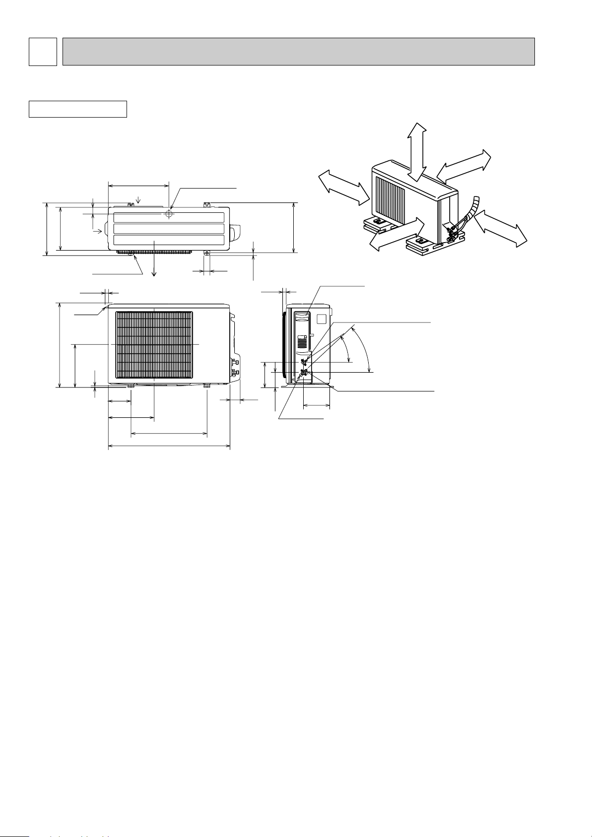
800
302.5
500 Bolt pitch for installation
150
22.3
Handle
550
280
164.5
99.5
170.5
23
Service panel
Service port
285
344.5
44
400
Air in
Air out
Air in
17.5
Bolt pitch for
installation
304~325
40
Liquid refrigerant pipe joint
Refrigerant pipe (flared) [6.35
Gas refrigerant pipe joint
Refrigerant pipe (flared) [9.52
43-
35-
2 holes 10X21
(MUH-GA25
/GA35VB)
REQUIRED SPACE
Basically open 100mm or more
without any obstruction in front
and on both sides of the unit.
350m
m
or m
ore
200m
m
or m
ore
100mm or more
100mm or more
Open two sides of left,
right, or rear side.
Drain hole [42
OUTLINES AND DIMENSIONS
MUH-GA20VB MUH-GA25VB MUH-GA35VB
OUTDOOR UNIT
Unit: mm
6
6
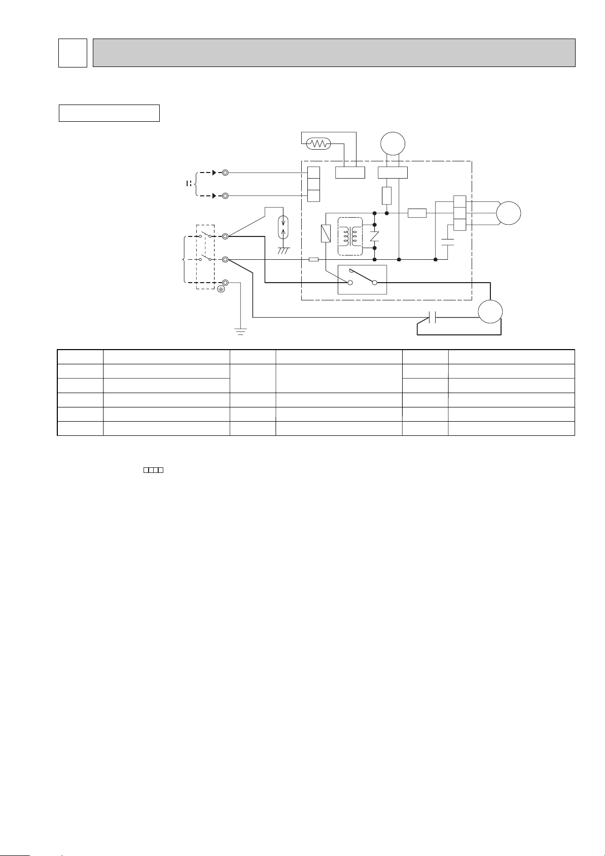
SYMBOL
T61
TB1,TB2
21S4
52C
SYMBOL
MF
NR61
RT61
SR61,SR62
SYMBOL
C1
C65
DSAR
F61
MC
NAME
NAME NAME
COMPRESSOR CAPACITOR
OUTDOOR FAN CAPACITOR
SURGE ABSORBER
FUSE(T2AL250V)
COMPRESSOR(INNER PROTECTOR)
VARISTOR
DEFROST THERMISTOR
SOLID STATE RELAY
TRANSFORMER
TERMINAL BLOCK
R.V. COIL
COMPRESSOR CONTACTOR
OUTDOOR FAN MOTOR
(INNER FUSE)
TAB20
PE
N
3
TB2
N
L
TB1
BRN
321
CN711
CN730
BLU
NR61
RT61
21S4
CN661
C65
123
SR61
SR62
CN721
T61
WHT
C
MC
S
R
RED
BLK
C1
F61
BRN
DSAR
CIRCUIT
BREAKER
BLU
POWER SUPPLY
~/N 230V 50Hz
12V
TO INDOOR
UNIT
CONNECTING
RED
BLK
GRN/YLW
3
52C
4
BLK
WHT
RED
MF
WIRING DIAGRAM
MUH-GA20VB MUH-GA25VB MUH-GA35VB
OUTDOOR UNIT
NOTE:1. About the indoor side electric wiring refer to the indoor unit electric wiring diagram for servicing.
2. Use copper conductors only. (For field wiring)
3. Symbols below indicate.
/: Terminal block, : Connector
7
7
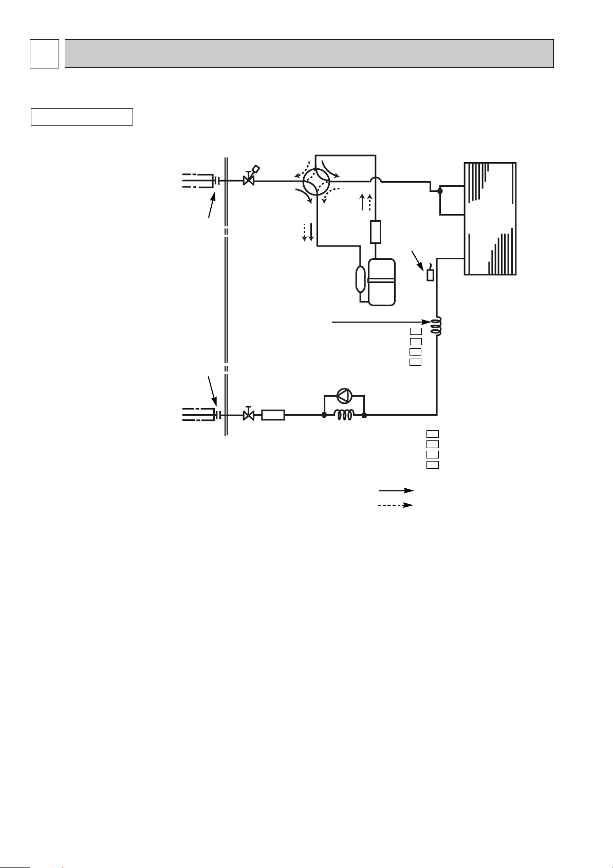
REFRIGERANT SYSTEM DIAGRAM
MUH-GA20VB MUH-GA25VB MUH-GA35VB
OUTDOOR UNIT
Refrigerant pipe [ 9.52
(with heat insulator)
Stop valve
(with service
Flared connection
Flared connection
Refrigerant pipe [6.35
(with heat insulator)
port)
Strainer
#100
Stop valve
Capillary tube
[3.0x[1.4x700 (MUH-GA20VB - )
[3.0x[1.4x900 (MUH-GA20VB - )
[3.0x[1.4x1000(MUH-GA25VB - )
[3.0x[1.6x1500(MUH-GA25VB - )
[3.0x[1.4x500 (MUH-GA35VB)
Capillary tube
[3.0x[1.4x500 (MUH-GA20VB - )
[3.0x[1.4x300 (MUH-GA20VB - , MUH-GA35VB)
[3.0x[1.4x600 (MUH-GA25VB - )
[3.0x[1.6x750 (MUH-GA25VB - )
4-way valve
Muffler
Check valve
Defrost
thermistor
RT61
Compressor
Unit:mm
Outdoor
heat
exchanger
E1
E2
E1
E2
R.V. coil
heating ON
cooling OFF
E1
E2
E1
E2
Refrigerant flow in cooling
Refrigerant flow in heating
8
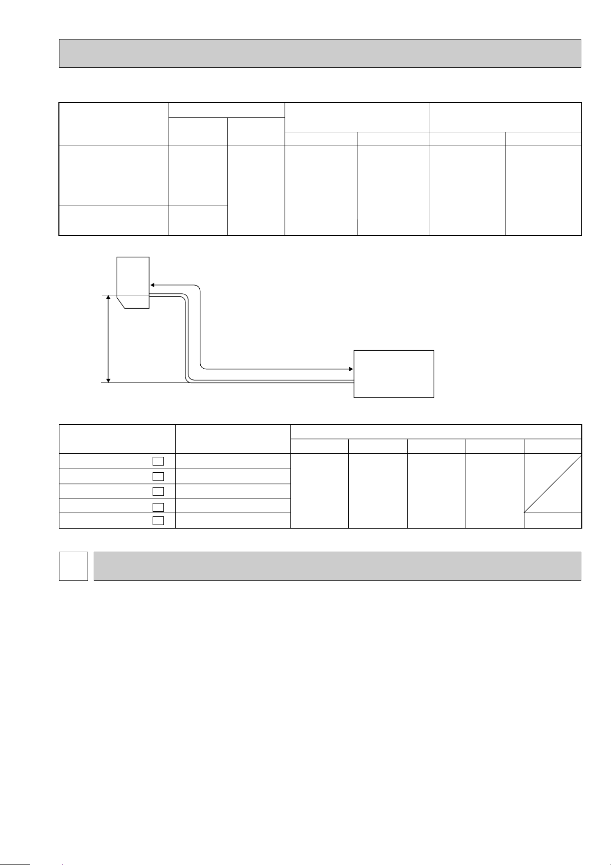
MAX. REFRIGERANT PIPING LENGTH
Refrigerant piping : m
Model
Max. lengthAMax. height
B
Piping size O.D : mm
Gas
Liquid
Length of connecting pipe : m
Indoor unit
Outdoor unit
MUH-GA20VB
MUH-GA25VB
MUH-GA35VB
20
25
10
9.52
MAX. HEIGHT DIFFERENCE
Indoor
unit
Refrigerant Piping
Max. height
B
Max. length
A
ADDITIONAL REFRIGERANT CHARGE(R410A : g)
Model
MUH-GA20VB MUH-GA20VB -
MUH-GA25VB MUH-GA25VB MUH-GA35VB -
Outdoor unit precharged
E1
E2
E1
E2
E1
650
600
800
650
800
7m
0
Gas 0.43
6.35
Liquid 0.5
Outdoor unit
Refrigerant piping length (one way)
10m
60
15m
160
Calculation : Xg = 20g/m x (A-7)m
20m
260
Gas 0
Liquid 0
25m
360
8
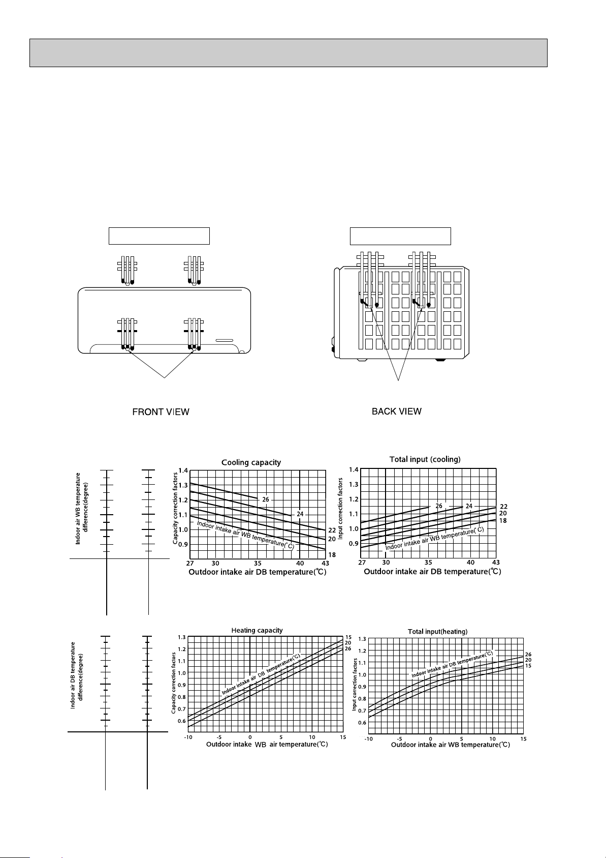
PERFORMANCE CURVES
MUH-GA20VB MUH-GA25VB MUH-GA35VB
The standard data contained in these specifications apply only to the operation of the air conditioner under normal conditions,
since operating conditions vary according to the areas where these units are installed. The following information has been provided to clarify the operating characteristics of the air conditioner under the conditions indicated by the performance curve.
(1) GUARANTEED VOLTAGE
198~264V
(2) AIR FLOW
Air flow should be set at MAX.
(3) MAIN READINGS
(1) Indoor intake air wet-bulb temperature : °CWB
(2) Indoor outlet air wet-bulb temperature : °CWB
(3) Outdoor intake air dry-bulb temperature : °CDB
(4) Total input: W
(5) Indoor intake air dry-bulb temperature : °CDB
(6) Outdoor intake air wet-bulb temperature : °CWB
(7) Total input : W
Indoor air wet/dry-bulb temperature difference on the left side of the chart on page 10 shows the difference between the
indoor intake air wet/dry-bulb temperature and the indoor outlet air wet/dry-bulb temperature for your reference at service.
9
}
}
Cooling
Heating
MSC-GA20VB
MUH-GA20VB
MUH-GA35VB
MSC-GA35VB
MUH-GA25VB
MSC-GA25VB
8.5
7.8
7.1
6.4
5.8
5.1
10.0
9.2
8.3
7.5
6.8
6.0
11.0
10.0
9.1
8.2
7.4
6.5
20.0
18.5
16.9
15.4
13.9
12.3
10.8
9.2
19.2
17.8
16.3
14.8
13.3
11.8
10.4
8.9
MSC-GA20VB
MUH-GA20VB
MUH-GA25VB
MSC-GA25VB
MUH-GA35VB
MSC-GA35VB
24.0
22.1
20.3
18.4
16.6
14.7
12.9
11.1
How to measure the indoor air wet-bulb/dry-bulb temperature difference
1. Attach at least 2 sets of wet-and dry-bulb thermometers to the indoor air intake as shown in the figure, and at least 2 sets
of wet-and dry-bulb thermometers to the indoor air outlet. The thermometers must be attached to the position where air
speed is high.
2. Attach at least 2 sets of wet-and dry-bulb thermometers to the outdoor air intake.
Cover the thermometers to prevent direct rays of the sun.
3. Check that the air filter is cleaned.
4. Open windows and doors of room.
5. Press the EMERGENCY OPERATION switch once(twice) to start the EMERGENCY COOL
(HEAT) MODE.
6. When system stabilizes after more than 15 minutes, measure temperature and take an average temperature.
7. 10 minutes later, measure temperature again and check that the temperature does not change.
INDOOR UNIT
Wet-and dry-bulb
thermometers
8-1.CAPACITY AND THE INPUT CURVES
OUTDOOR UNIT
Wet-and dry-bulb
thermometers
NOTE:The above curves are for the heating operation without any frost.
10
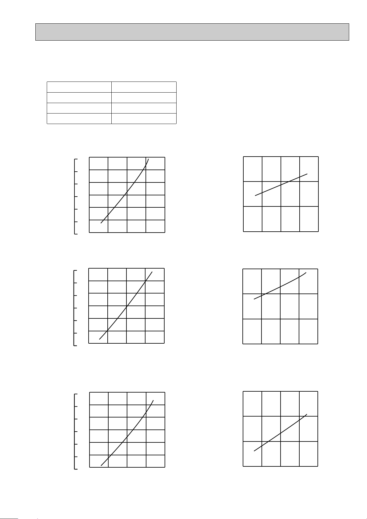
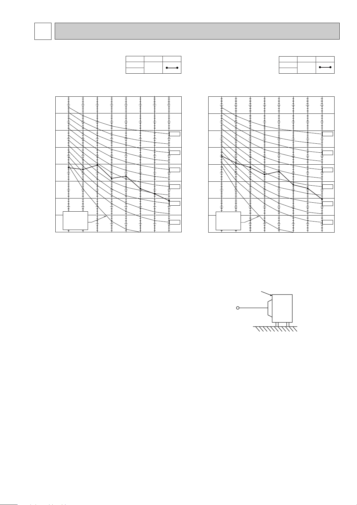
8-2.OUTDOOR LOW PRESSURE AND OUTDOOR UNIT CURRENT
18 32
7
8
9
10
11
12
13
230V
15 20
50
25
6030 70(%)
35(:)
0.7
0.8
0.9
1.0
1.1
1.2
1.3
15 20
50
25
60
30
70(%)
35(:)
1
2
4
3
18 32
230V
18 32
230V
15 20
50
25
6030 70(%)
35(:)
0.7
0.8
0.9
1.0
1.1
1.2
1.3
7
8
9
10
11
12
13
15 20
50
25
60
30
70(%)
35(:)
1
2
4
3
18 32
230V
18 32
230V
15 20
50
25
60
30
70(%)
35(:)
0.7
0.8
0.9
1.0
1.1
1.2
1.3
7
8
9
10
11
12
13
15 20
50
25
6030 70(%)
35(:)
3
4
5
6
18 32
230V
COOL operation
① Both indoor and outdoor unit are under the same temperature/humidity condition.
Dry-bulb temperature
20
25
Relative humidity(%)
50
60
30 70
➁ Air flow should be set at MAX.
③ The unit of pressure has been changed to MPa on the international system of units(SI unit system).
The conversion factor is : 1(MPa[Gauge]) =10.2(kgf/ff[Gauge] )
(kgf/F[Gauge])(MPa[Gauge])
Outdoor low pressure
(kgf/F[Gauge])(MPa[Gauge])
Outdoor unit current (A)
Ambient temperature(˚C)
Ambient humidity(%)
MUH-GA25VB
MUH-GA20VBMUH-GA20VB
Ambient temperature(˚C)
Ambient humidity(%)
MUH-GA25VB
(kgf/F[Gauge])(MPa[Gauge])
Outdoor low pressure
Ambient temperature(˚C)
Ambient humidity(%)
MUH-GA35VB
Outdoor low pressure
Ambient temperature(˚C)
Ambient humidity(%)
Outdoor unit current (A)
Ambient temperature(˚C)
Ambient humidity(%)
MUH-GA35VB
Outdoor unit current (A)
Ambient temperature(˚C)
Ambient humidity(%)
11
 Loading...