

Mitsubishi Electric MSH-18NV, MUH-18NV Service Manual
SERVICE MANUAL
SPLIT-TYPE, HEAT PUMP AIR CONDITIONERS
CONTENTS
1. TECHNICAL CHANGES····································2
2. PART NAMES AND FUNCTIONS······················2
3. SPECIFICATION·················································4
4. OUTLINES AND DIMENSIONS························ 5
5. WIRING DIAGRAM ············································6
6. REFRIGERANT SYSTEM DIAGRAM················7
7. PERFORMANCE CURVES································8
8. MICROPROCESSOR CONTROL ····················10
9. SERVICE FUNCTIONS ····································19
10. TROUBLESHOOTING······································21
11. DISASSEMBLY INSTRUCTIONS·····················30
12. PARTS LIST······················································34
13. OPTIONAL PARTS···········································37
Wireless type
Model
MSH-18NV -
(WH)
· MUH-18NV -
E4E4
No. OB229
REVISED EDITION-A
MSH-18NV -
E4
•Refer to the Service Manual OB185 REVISED EDITION C when MSH-18NV- is connected with
MXZ-32NV- or MXZ-32NV- as multi system units.
•Refer to the Service Manual OB227 REVISED EDITION-B when MSH-18NV- is connected with
MXZ-32RV- as multi system units.
E1
E4
E2E1
E4
Revision:
●Information for connecting MSH-18NV- with
MXZ-32RV- was described.
●TROUBLESHOOTING has been modified.
E1
E4
2
PART NAMES AND FUNCTIONS
2
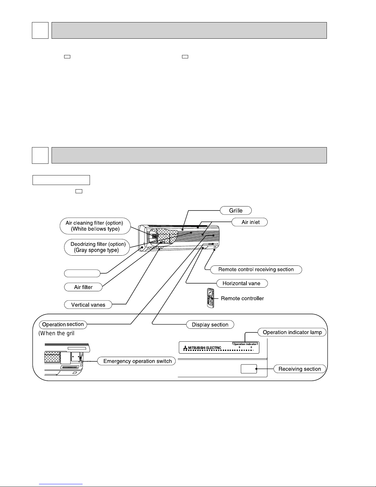
INDOOR UNIT
(When the grille is open)
Front panel
MSH-18NV -
E4
TECHNICAL CHANGES
MSH-18NV- became possible the connection to MXZ-32RV- as multi system units.
E1E4
1
3
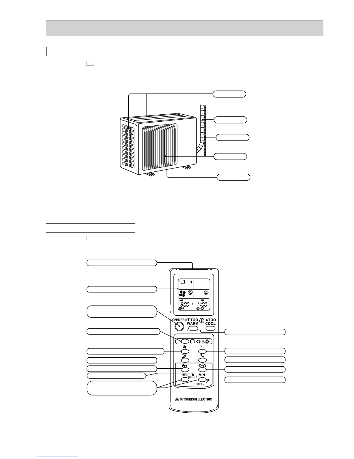
Drainage hose
Piping
Air inlet
Air outlet
Drain outlet
(back and side)
OUTDOOR UNIT
MUH-18NV -
E4
TEMPERATURE buttons
VANE CONTROL button
SWING button
OFF-TIMER button
RESET button
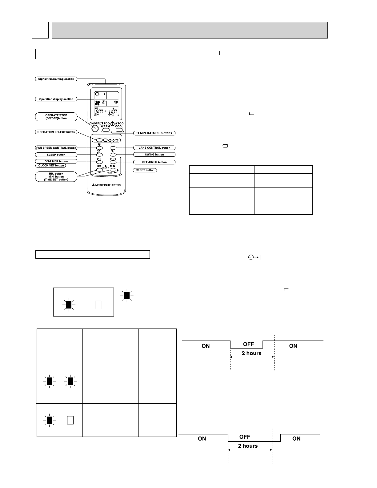
Signal transmitting section
Operation display section
OPERATE/STOP
(ON/OFF)button
OPERATION SELECT button
FAN SPEED CONTROL button
SLEEP button
ON-TIMER button
CLOCK SET button
HR. button
MIN. button
(TIMER SET button)
MSH-18NV -
E4
REMOTE CONTROLLER
4
Capacity
Electrical data
Compressor
Indoor
fan motor
Outdoor
fan motor
Dimensions
Weight
Special remarks
Model
Function
Power supply
Coefficient of performance(C.O.P)
Capacity
Dehumidification
Air flow(Hi)
Power outlet
Running current
Power input
Auxiliary heater
Power factor
Starting current
Compressor motor current
Fan motor current
Model
Output
Winding resistance(at20:)
Model
Winding resistance(at20:)
Model
Winding resistance(at20:)
Indoor unit
Outdoor unit
Indoor unit
Outdoor unit
Air direction
Sound level
(Hi)
Fan speed
(Hi)
Fan speed
regulator
Refrigerant filling capacity(R-22)
Refrigerating oil (Model)
Thermistor
Width
Height
Depth
Width
Height
Depth
Indoor unit
Outdoor unit
Indoor unit
Outdoor unit
Indoor unit
Outdoor unit
RT11(at25:)
RT12(at25:)
RT61(at0:)
kW
R/h
K /h
A
A
W
A(kW)
%
A
A
A
W
"
"
"
mm
mm
mm
mm
mm
mm
kg
kg
dB
dB
rpm
rpm
kg
cc
k"
k"
k"
MSH-18NV -
E4
Single phase,220-240V,50Hz
INDOOR 756 OUTDOOR 2142-2244
15
52-58
INDOOR 0.25 OUTDOOR 0.39
PH-36VPET
1600
C-R1.03 C-S2.04
RA4V27-EA or EF
WHT-BLK183.8 BLK-RED250.5
RA6V50-OF or OG
WHT-BLK116.4 BLK-RED111.0
1,015
320
190
850
605
290
14
54
5
42
52
1,180
810-845
4
1
1.65
900 (MS32N1)
10
10
33.18
Cooling
5.1
2.5
9.4-9.2
2,030-2,120
—
98-96
8.76-8.56
2.51-2.41
Heating
5.4
—
9.2-9.0
1,980-2,070
—
98-96
8.56-8.36
2.73-2.61
WMSH-18NV- E4 (INDOOR UNIT)
Cooling Heating
Single phase,220-240V,50Hz
— —
—
756
10
0.28
60
—
97-89
—
—
0.25
—
—
—
—
RA4V27-EA or EF
WHT-BLK183.8 BLK-RED250.5
—
—
1,015
320
190
—
—
—
14
—
5
42
—
1,180
—
4
—
—
—
10
10
—
wRefer to the Service Manual OB185 REVISED EDITION C when MSH-18NV- is connected with
MXZ-32NV- or MXZ-32NV- as multi system units.
wRefer to the Service Manual OB227 REVISED EDITION-B when MSH-18NV- is connected with
MXZ-32RV- as multi system units.
E1
E4
E2E1
E4
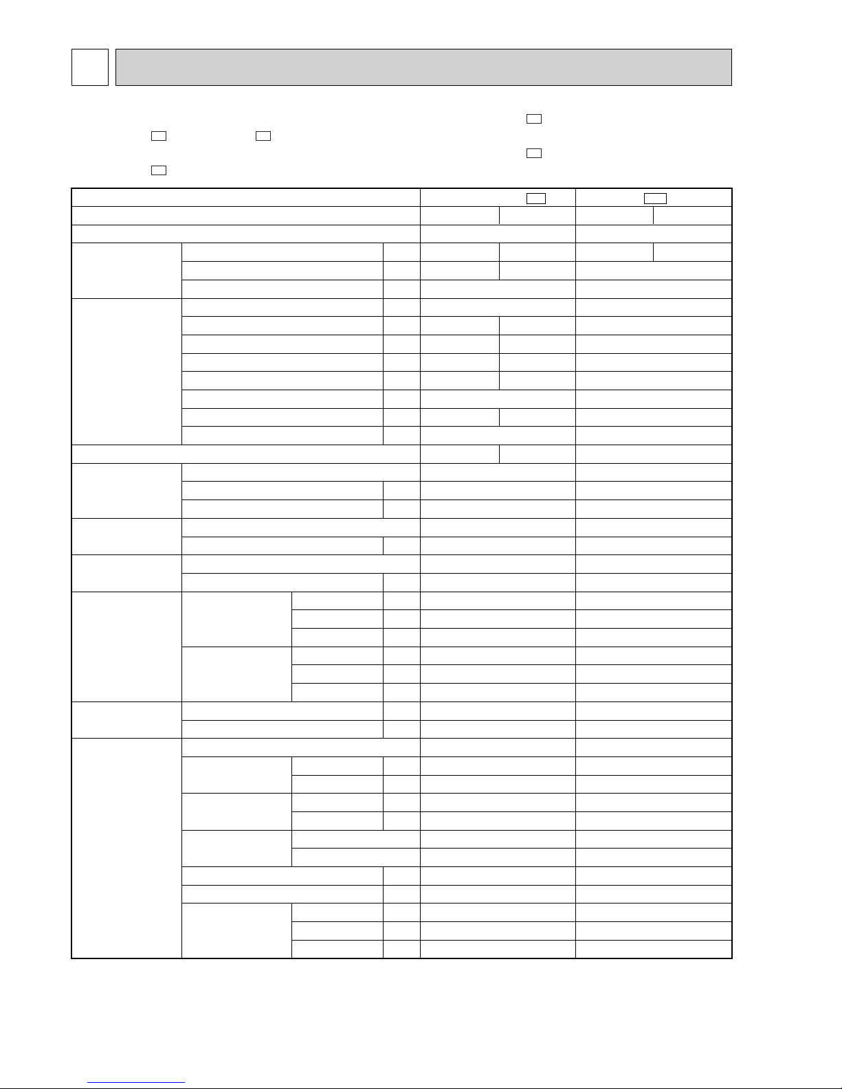
SPECIFICATION
3
NOTE:Test conditions
Cooling : Indoor DB27°C / WB19°C Heating : Indoor DB20°C /WB15.5°C
Outdoor DB35°C / WB24°C Outdoor DB7°C / WB6°C
5
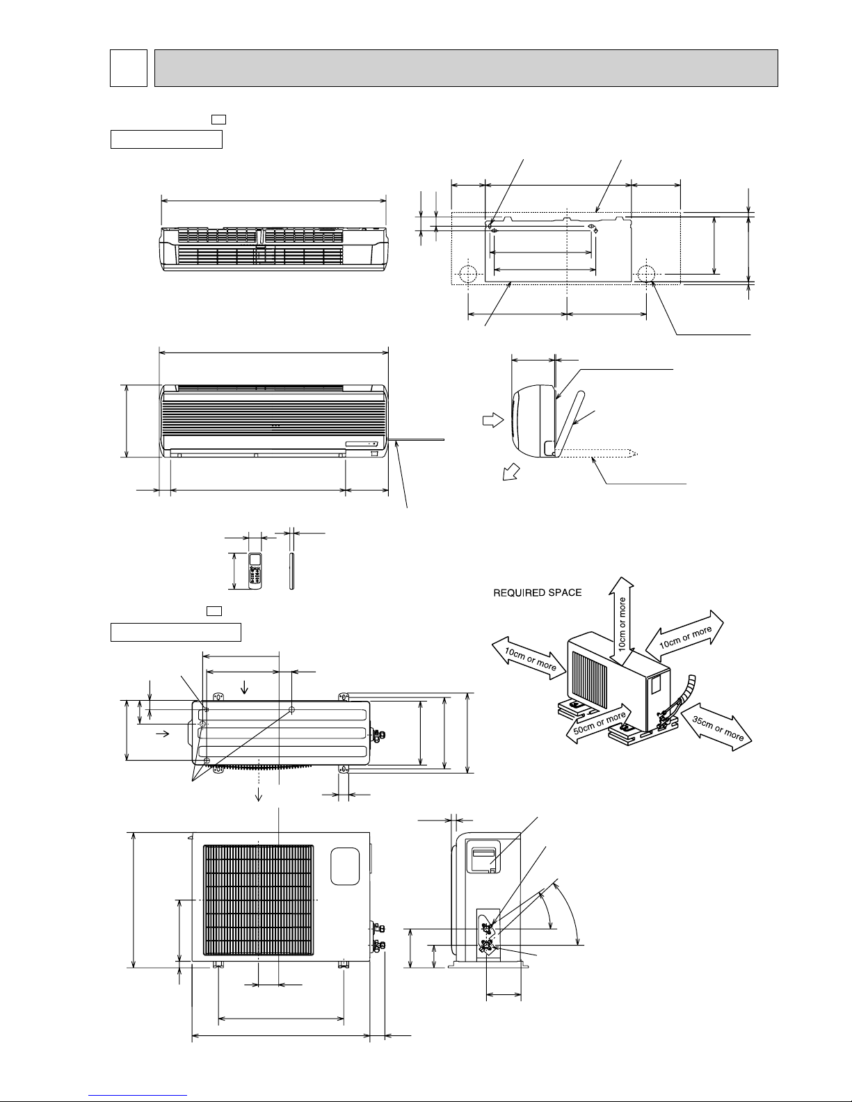
OUTLINES AND DIMENSIONS
4
Unit: mm
OUTDOOR UNIT
MSH-18NV -
E4
MUH-18NV -
E4
INDOOR UNIT
3 297
450
450
352438
254
20
60
40
150 648 217
5190
995
19077550
320
1015
17.5
160
56
4holes 11✕20
Indoor unit
Installation plate
Power supply cord
Lead to right 2m
Lead to left 1m
Wall hole [75
Installation plate
Liquid line [8-0.5m
Gas line [12-0.43m
Insulation [50 O.D
[28 I.D
Insulation [28
Drain hose [16
Air out
{
Air in
If the right/left sides or
back side is vacant, the
front has only to be 50cm
unobstructed.
If the front or right/left sides
are vacant, the top has only
to be 10cm unobstructed.
Drainage
3holes [33
Air out
Air in
Air in
Service panel
Liquid refrigerant
pipe joint
Refregerant pipe
(flared) [6.35
Gas refregerant
pipe joint
Refregerant pipe
(flared) [15.88
35-
30-
30
100
161
157
74
850
500
183
20
292
605
248
35
350
50
290
310
345
20
355
90
Drainage
hole [16.2
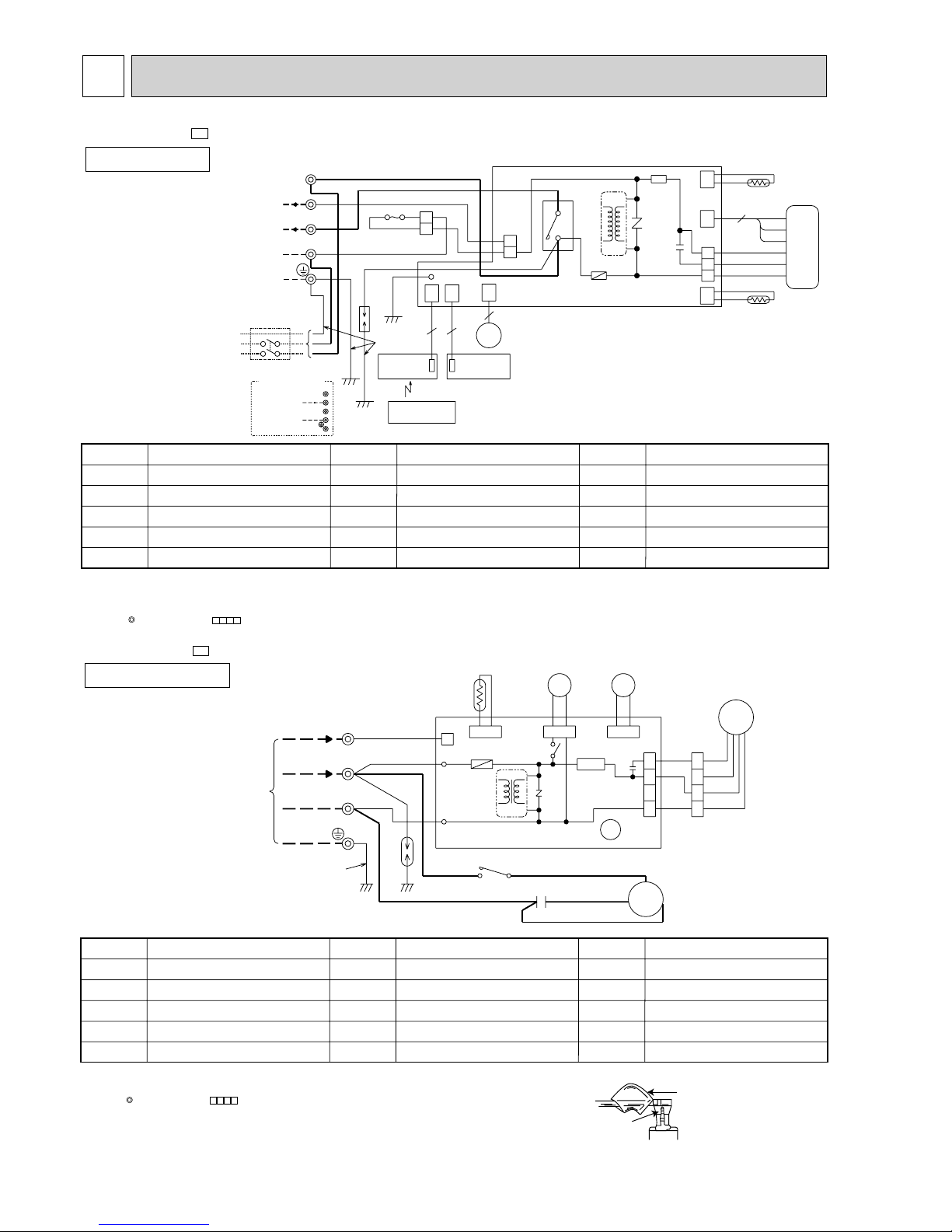
6
MSH-18NV -
E4
MUH-18NV -
E4
MODEL WIRING DIAGRAM
MODEL WIRING DIAGRAM
INDOOR UNIT
OUTDOOR UNIT
CIRCUIT BREAKER
N
2
12VDC
L
50Hz
CORD
POWER
SUPPLY
~/N 220-240V
F11
NR11
TRANS
HIC1
12VDC
220-240V~
DSAR
BRN
GRN/YLW
LD1
DISPLAY
P.C.BOARD
RECEIVER
P.C.BOARD
33
101
102
CN CN
1
TO OUTDOOR
UNIT
CONNECTING
N
BLU
GRN/YLW
MV
151
CN
5
BLU
3
BLU
ELECTRONIC CONTROL P.C BOARD
REMOTE
CONTROLLER
3
BLU
BLU
RED
2
1
F12
2
WHT
BRN
BRN
L
3
TB
CN201
CN211
121
CN
112
CN
3
4
RT11
BRN
YLW
RED
GRY
WHT
BLK
RT12
52C
IC141
C11
1
2
4
MF
FOR MULTI SYSTEM
TO OUTDOOR
UNIT
CONNECTING
3
111
CN
❈
❈
❈
❈
❈
❈
SYMBOL
RT12
TB
52C
SYMBOL
HIC1
MF
MV
NR11
RT11
SYMBOL
C11
DSAR
F11
F12
IC141
NAME
NAME NAME
INDOOR FAN CAPACITOR
SURGE ABSORBER
FUSE(3.15A)
THERMAL FUSE(93:)
HYBRID IC
DC/DC CONVERTER
INDOOR FAN MOTOR(INNER FUSE)
VANE MOTOR
VARISTOR
ROOM TEMPERATURE THERMIST OR
INDOOR COIL THERMISTOR
TERMINAL BLOCK
CONTACTOR
CN720
52C
1
X62
21S4
CN721
MF
SR61
MC
WHT
WHT
WHT
VLT
VLT
COM
52C
TAB21
DSAR
ORN
WHT
WHT
RED
RED
RED
WHT
BLU
BLU
RED
BLK
CN730
C65
DEICER P.C.BOARD
RT61
F61
IC881
X62
CN711
BLK
TRANS
TAB20
BLK
R
C
C1
FROM
INDOOR UNIT
CONNECTING
GRN/YLW
12VDC
TB
220-240V~
N
2
3
4
1
4
3
2
1
BLK
BLK
CN661
NO
NR61
S
3
2
❈
❈
❈
❈
❈
NAME
NAME NAME
SYMBOL
C1
C65
DSAR
F61
IC881
SYMBOL
TB
X62
21S4
52C
SYMBOL
MC
MF
NR61
RT61
SR61
COMPRESSOR CAPACITOR
OUTDOOR FAN CAPACITOR
SURGE ABSORBER
FUSE(2A)
DC/DC CONVERTER
COMPRESSOR(INNER THERMOSTAT)
OUTDOOR FAN MOTOR(INNER THERMOSTAT)
VARISTOR
DEFROST THERMISTOR
SOLID STATE RELAY
TERMINAL BLOCK
REVERSING VALVE COIL RELAY
REVERSING VALVE COIL
CONTACTOR
NOTE:1. For the outdoor electric wiring refer to the outdoor unit electric wiring diagram for servicing.
2. Use copper conductors only.(For field wiring)
3. Symbols below indicate.
: Terminal block, : Connector
WIRING DIAGRAM
5
Sleeve
Locking lever
NOTE: 1. Use copper conductors only (For field wiring).
2. Symbols below indicate.
: Terminal block, : Connector
3. “❈”show the terminals with a lock mechanism, so they cannot be removed when you pull
the lead wire.
Be sure to pull the wire by pushing the locking lever (projected part) of the terminal with a finger.
1.Slide the sleeve.
2.Pull the wire while
pushing the locking
lever.
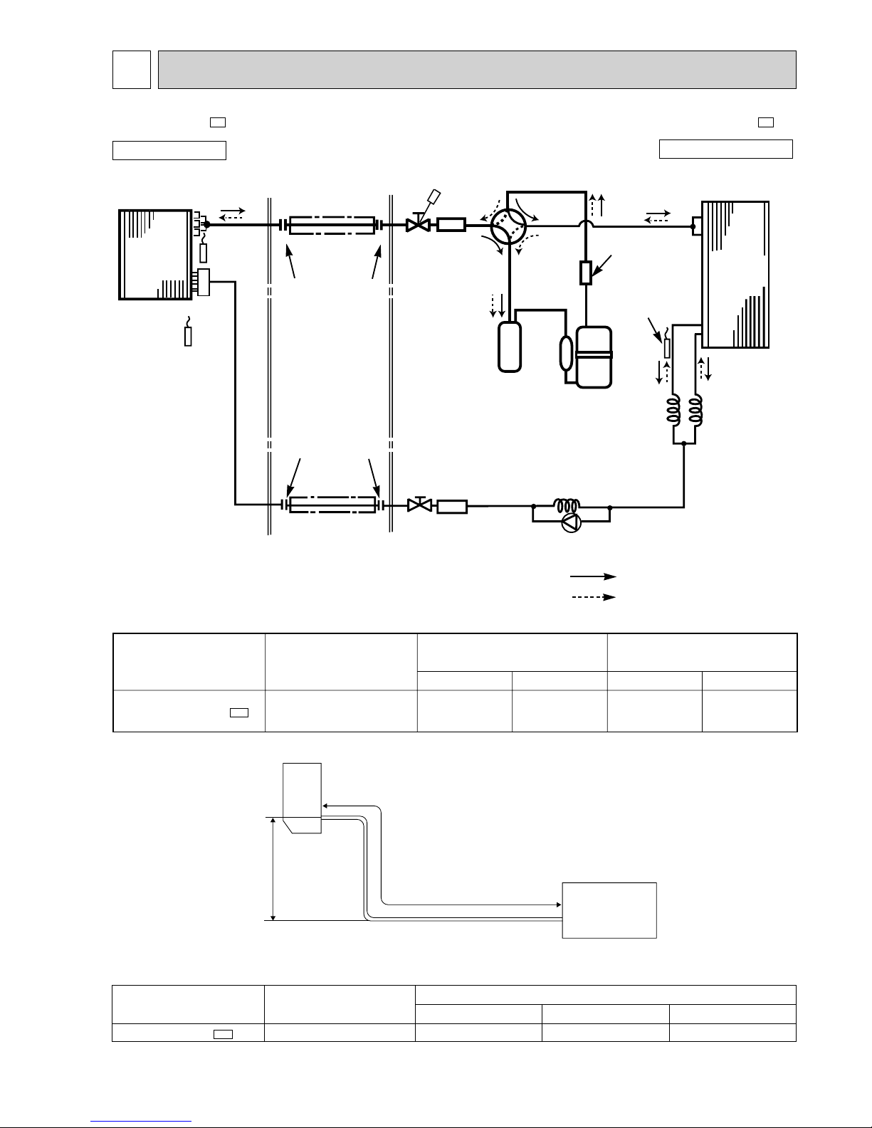
7
REFRIGERANT SYSTEM DIAGRAM
6
MSH-18NV -
E4
MUH-18NV -
E4
INDOOR UNIT
OUTDOOR UNIT
Indoor
heat
exchanger
Room temperature
thermistor
RT11
Refrigerant pipe [15.88
(Option)
Flared connection
Flared connection
Indoor coil
thermistor
RT12
Refrigerant pipe[ 6.35
(Option)
Stop valve
Strainer
Check
valve
Capillary tube
[3.0o[2.0o500
Capillary tube
[3.0o[1.6o750
(2 pcs)
Compressor
Accumulator
Stop valve
(with service port)
Muffler
Outdoor
heat
exchanger
Defrost
thermistor
RT61
Reversing valve coil
(4-way valve coil)
Heating ON
Cooling OFF
Refrigerant flow in cooling
Refrigerant flow in heating
(with heat insulator)
Strainer
Distributor
Reversing valve
(4- way valve)
Model
Piping size O.D : mm Length of connecting pipe : m
Refrigerant piping
Max. length : m
A
15
Indoor unit
Gas 0.43
Liquid 0.5
Gas
15.88
Liquid
6.35
Outdoor unit
Gas 0
Liquid 0
MSH-18NV - E4
Indoor
unit
wMax. Height
difference: 5m
A
Refrigerant Piping
Max. Length
w Height difference should be within 5m
regardless of which unit, indoor or outdoor position is high.
Outdoor unit
Model
MSH-18NV -
E4
Refrigerant piping length (one way)
Outdoor unit precharged
(up to 7m)
1650
15m
400
7m
0
10m
150
MAX. HEIGHT DIFFERENCE
ADDITIONAL REFRIGERANT CHARGE(R-22 : g)
MAX. REFRIGERANT PIPING LENGTH
Calculation : Xg=50g/m ✕ (A-7)m
(with heat insulator)
8
11.2
7.2
8.2
9.1
10.1
12.2
MSH-18NV - E4
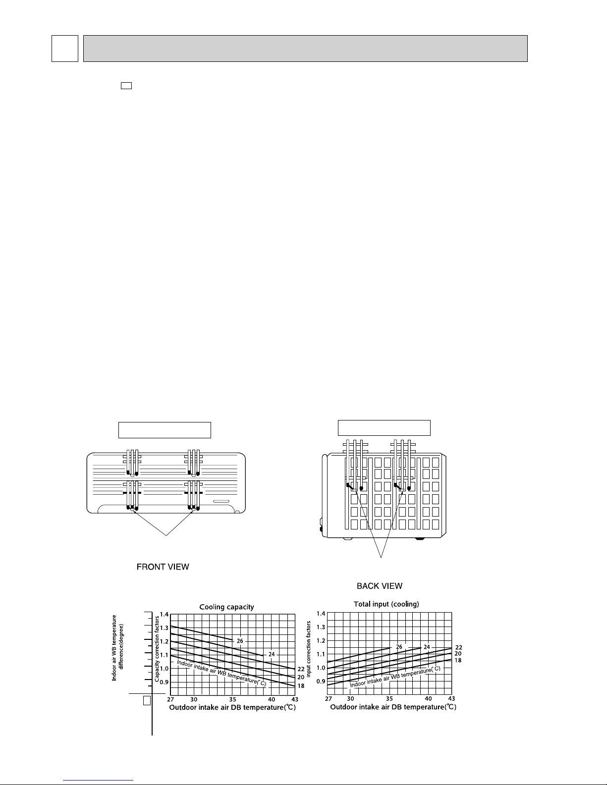
7
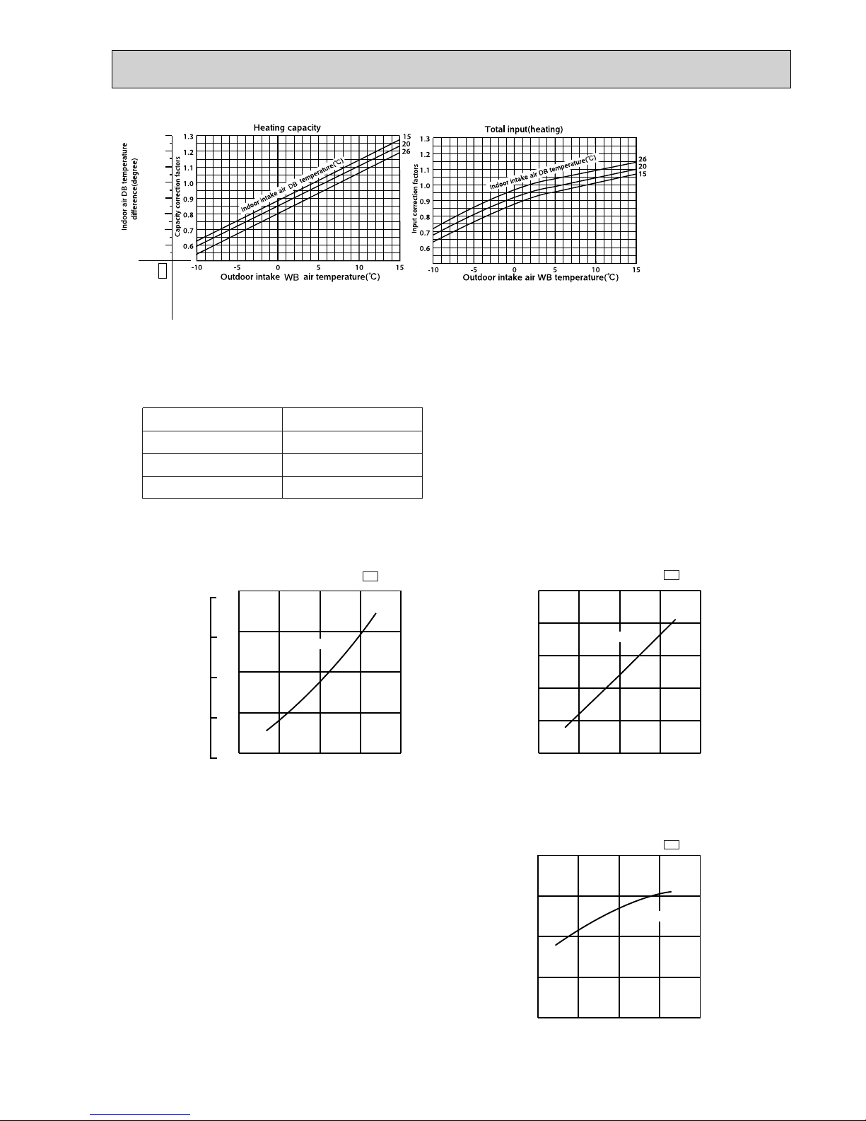
The standard data contained in these specifications apply only to the operation of the air conditioner under normal conditions,
since operating conditions vary according to the areas where these units are installed. The following information has been
provided to clarify the operating characteristics of the air conditioner under the conditions indicated by the performance curve.
(1) GUARANTEED VOLTAGE
Rated voltage : ±10% (198 ~ 264V
), 50Hz
(2) AIR FLOW
Air flow should be set at MAX.
(3) MAIN READINGS
(1) Indoor intake air wet-bulb temperature : °CWB
(2) Indoor outlet air wet-bulb temperature : °CWB
(3) Outdoor intake air dry-bulb temperature : °CDB
(4) Total input: W
(5) Indoor intake air dry-bulb temperature : °CDB
(6) Outdoor intake air wet-bulb temperature : °CWB
(7) Total input : W
Indoor air wet/dry-bulb temperature difference on the left side of the chart on this page and next page shows the
difference between the indoor intake air wet/dry-bulb temperature and the indoor outlet air wet/dry-bulb temperature for
your reference at service.
How to measure the indoor air wet-bulb/dry-bulb temperature difference
1. Attach at least 2 sets of wet-and dry-bulb thermometers to the indoor air intake as shown in the figure, and at least 2 sets
of wet-and dry-bulb thermometers to the indoor air outlet. The thermometers must be attached to the position where air
speed is high.
2. Attach at least 2 sets of wet-and dry-bulb thermometers to the outdoor air intake.
Cover the thermometers to prevent direct rays of the sun.
3. Check that the air filter is cleaned.
4. Open windows and doors of room.
5. Press the EMERGENCY OPERATION switch once(twice) to start the EMERGENCY COOL(HEAT) MODE.
6. When system stabilizes after more than 15 minutes, measure temperature and take an average temperature.
7. 10 minutes later, measure temperature again and check that the temperature does not change.
INDOOR UNIT
OUTDOOR UNIT
}
}
Cooling
Heating
PERFORMANCE CURVES
Wet-and dry-bulb
thermometers
Wet-and dry-bulb
thermometers
MSH-18NV -
E4
9
28.0
25.9
23.7
21.6
19.4
17.2
15.1
12.9
MSH-18NV - E4
NOTE:The above curves are for the heating operation without any frost.
OUTDOOR LOW PRESSURE AND OUTDOOR UNIT CURRENT
COOL operation
11
Both indoor and outdoor unit are under the same temperature/humidity condition.
22
Air flow should be set at MAX.
Dry-bulb temperature
Relative humidity(%)
20
50
25
60
30 70
33
The unit of pressure has been changed to MPa on the international system of units(SI unit system).
The conversion factor is : 1(MPa • G) =10.2(kgf/ff• G)
15 20
50
25
60
30
70(%)
35(:)
0.3
0.4
0.5
0.6
0.7
18 32
220V/240V
7
6
5
4
3
15 20
50
25
60
30
70(%)
35(:)
6
7
8
9
10
11
18 32
220V/240V
MUH-18NV -
E4
MUH-18NV -
E4
Outdoor low pressure
Ambient temperature(˚C)
Ambient humidity(%)
Ambient temperature(˚C)
Ambient humidity(%)
Outdoor unit current (A)
(kgf/F•G)(MPa•G)
HEAT operation
Condition indoor:Dry bulb temperature 20.0°C
Wet bulb temperature 14.5°C
Outdoor:Dry bulb temperature 7,15,20°C
Wet bulb temperature 6,12,14.5°C
MUH-18NV -
E4
5 10152025
7
8
9
10
11
7
21
220V/240V
(:)
Outdoor unit current (A)
Ambient temperature(˚C)
10
MICROPROCESSOR CONTROL
8
Once the operation mode are set, the same operation mode
can be repeated by simply turning the OPERATE/STOP
(ON/OFF) button ON.
Indoor unit receives the signal with a beep tone.
When the system turns off, 3-minute time delay will operate to
protect system from overload and compressor will not restart
for 3 minutes.
8-1. “I FEEL CONTROL” ( ) OPERATION
(1) Press OPERATE/STOP (ON/OFF) button on the remote
controller. Operation Indicator lamp of the indoor unit
turns on with a beep tone.
(2) Press OPERATION SELECT button to set “I FEEL
CONTROL”( ). Then a beep tone is heard.
(3) The operation mode is determined by the room
temperature at start-up of the operation.
lighting
not lighting
Approx. 2 :
or more
Difference
betweeen set
temperature
and room
temperature
Approx. 2 :
or less
This shows that the
air conditioner is
operating to reach
the target temperature.
Please wait unit the
target temperature is
obtained.
This shows that the
room temperature is
approaching the
target temperature.
Operation state
Indication
Operation Indicator
Operation Indicator lamp
The operation indicator at the right side of the indoor
unit indicates the operation state.
INDOOR UNIT DISPLAY SECTION
WIRELESS REMOTE CONTROLLER
Example
Previous operation
COOL mode of
“I FEEL CONTROL”
or COOL mode
• Once the mode is fixed, the mode does not change by
room temperature afterwards.
• Under the ON-TIMER ( ) operation, mode is
determined according to the room temperature as the
operation starts.
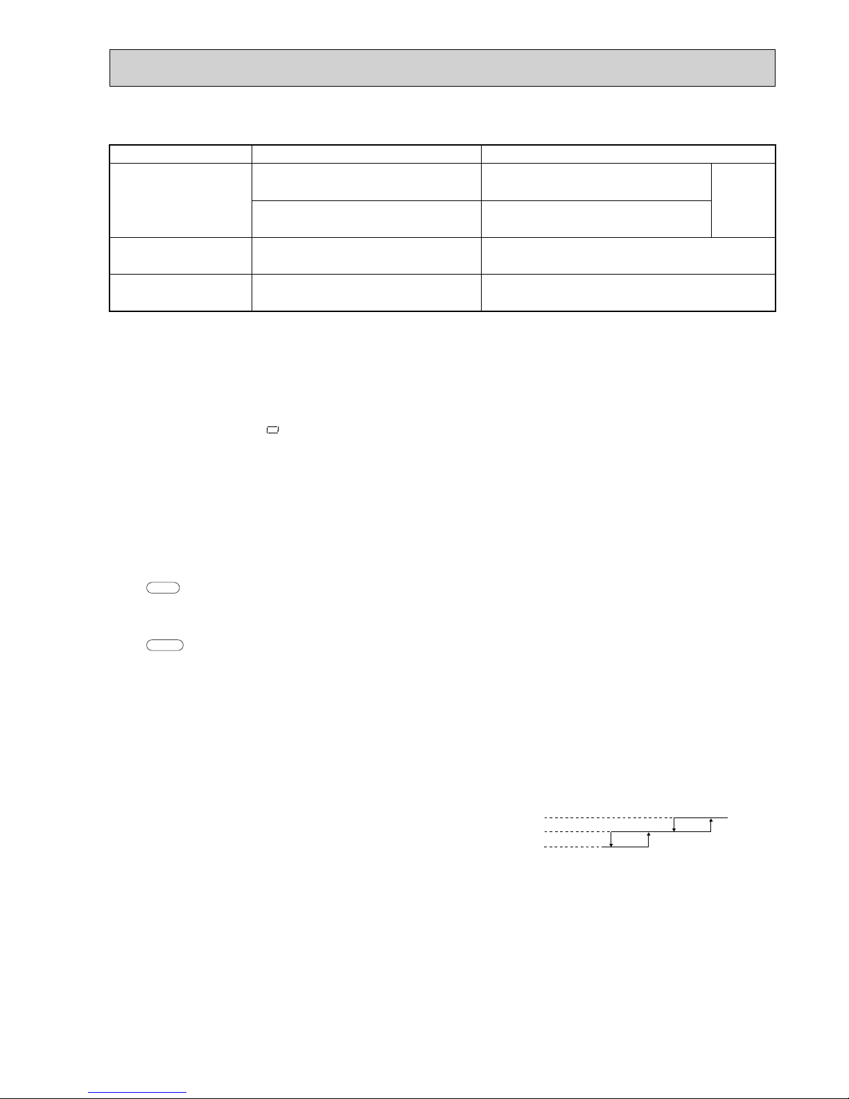
• When the system is stopped with the OPERATE/STOP
(ON/OFF) button on the remote controller, and restarted
within 2 hours in “I FEEL CONTROL” ( ) mode, the
system operates in previous mode automatically
regardless of the room temperature.
Mode
COOL mode of
"I FEEL CONTROL"
DRY mode of
"I FEEL CONTROL"
HEAT mode of
"I FEEL CONTROL"
Initial room temperature
25: or more
23:to 25:
less than 23:
Example
Previous operation
COOL mode of
“I FEEL CONTROL”
or COOL mode
When the system is restarted after 2 hours and more, the
operation mode is determined by the room temperature
at start-up of the operation.
Restart
COOL mode of
“I FEEL CONTROL”
Restart
COOL or DRY or
HEAT mode of “I FEEL
CONTROL” that
determined by room
temperature at start-up
of the operation.
MSH-18NV -
E4
11
Model
COOL mode of
"I FEEL CONTROL"
DRY mode of
"I FEEL CONTROL"
HEAT mode of
"I FEEL CONTROL"
Initial room temperature Initial set temperature
26:
26: or more
25: to 26:
less than 23:
23: to 25:
24:
Initial room temperature
minus 2:
Initial room temperature
minus 2:
❈1
❈1 When the system is restarted with the remote controller, the system operates with the previous set temperature
regardless of room temperature at restart.
The set temperature is calculated by the previous set temperature.
(5) TEMPERATURES buttons
In “I FEEL CONTROL” ( ) mode, set temperature is decided by the microprocessor based on the room temperature.
In addition, set temperature can be controlled by TOO WARM or TOO COOL buttons when you feel too cool or too warm.
Each time the TOO WARM or TOO COOL button is pressed,the indoor unit receives the signal and emits a beep tone.
• Fuzzy control
When the TOO COOL or TOO WARM button is pressed, the microprocessor changes the set temperature, considering
the room temperature, the frequency of pressing TOO COOL or TOO WARM button and the user’s preference to heat or
cool. So this is called “Fuzzy control”, and works only in “I FEEL CONTROL” mode.
In DRY mode of “I FEEL CONTROL”, the set temperature doesn’t change.
▲ TOO
COOL… To raise the set temperature 1~2 degrees(°C)
▼ TOO
WARM … To lower the set temperature 1~2 degrees(°C)
(4) The initial set temperature is decided by the initial room temperature.
1. Indoor fan speed control
Indoor fan operates at the set speed by FAN SPEED CONTROL button.
In AUTO the fan speed is as follows.
Initial temperature difference Fan Speed
Room temperature minus set temperature : 2 degrees or more
····························Hi
Room temperature minus set temperature : Between 1 and 2 degrees
·················Me
Room temperature minus set temperature : less than 1 degree
····························
Lo
— COOL mode of “I FEEL CONTROL” —
Difference between room
temperature and set temperature
during operation.
1deg. 1.7deg.
2deg. 4deg.
2. Coil frost prevention
① Temperature control
When the indoor coil thermistor RT12 reads 3°C or below, the coil frost prevention mode starts immediately.
However, the coil frost prevention doesn’t work for 5 minutes since the compressor has started.
The indoor fan operates at the set speed and the compressor stops for 5 minutes.
After that, if RT12 still reads below 3°C this mode prolonged until the RT12 reads over 3°C.
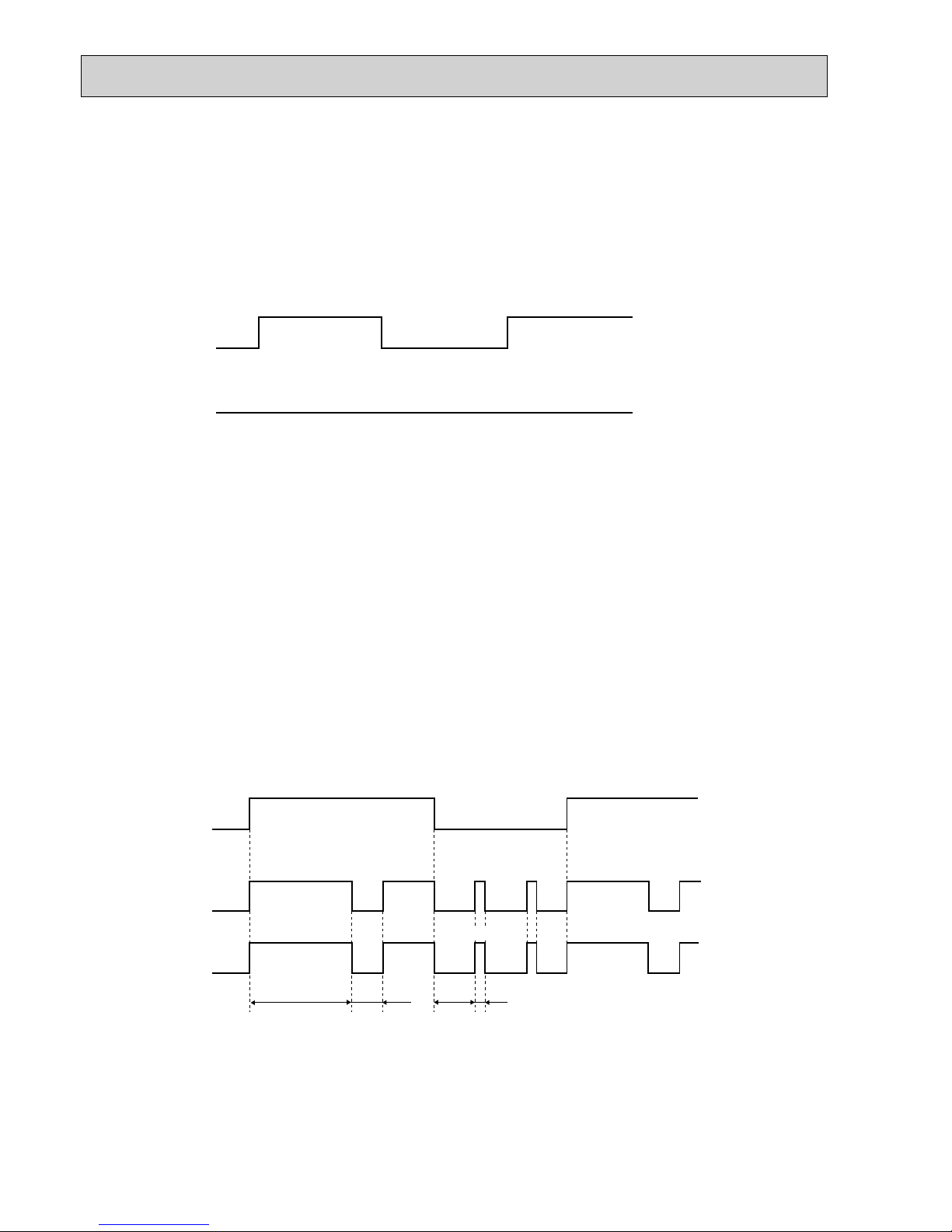
Operation time chart
Example
3. Coil frost prevention
• The operation is as same as coil frost prevention during COOL mode of “I FEEL CONTROL”.
• Indoor fan operates at the set speed and the compressor stops for 5 minutes, because protection(Coil frost
prevention) has the priority.
However, when coil frost prevention works while the compressor is not operating, it’s speed becomes Lo.
Thermostat
Indoor fan
Outdoor fan
Compressor
ON
8 min.
1 min.
4 min.
3 min.
ON
OFF
OFF
OFF
OFF
OFF
ON
ON
ON
ON
ON
ON
12
Compressor
Outdoor fan
OFF
ON
(continuously at set speed)
Indoor fan
ON
ON
OFF
Operation chart
Example
—DRY mode of “I FEEL CONTROL”—
The system for dry operation uses the same refrigerant circuit as the cooling circuit.
The compressor and the indoor fan are controlled by the room temperature.
By such controls, indoor flow amounts will be reduced in order to lower humidity without much room temperature
decrease.
1. Indoor fan speed control
Indoor fan operates at the set speed by FAN SPEED CONTROL button.
However, in AUTO fan operation, fan speed becomes Lo.
2. The operation of the compressor and indoor/ outdoor fan
Compressor operates by room temperature control and time control.
Set temperature is controlled to fall 2°C from initial room temperature.
Indoor fan and outdoor fan operate in the same cycle as the compressor.
•When the room temperature is 23°C or over:
When the thermostat is ON, the compressor repeats 8 minutes ON and 3 minutes OFF.
When the thermostat is OFF, the compressor repeats 4 minutes OFF and 1 minute ON.
•When the room temperature is under 23°C.
When the thermostat is ON, the compressor repeats 2 minutes ON and 3 minutes OFF.
When the thermostat is OFF, the compressor repeats 4 minutes OFF and 1 minute ON.
OFF
OFF
OFF
② Time control
When the three conditions as follows have been satisfied for 1 hour and 45 minutes, compressor stops for 3 minutes.
a. Compressor has been continuously operating.
b. Indoor fan speed is Lo or Me.
c. Room temperature is below 26°C.
When compressor stops, the accumulated time is cancelled and when compressor restarts, time counting starts from the
beginning.
Time counting also stops temporarily when the indoor fan speed becomes Hi or the room temperature exceeds
26°C.However, when two of the above conditions (b.and c.) are satisfied again.Time accumulation is resumed.
 Loading...