

Mitsubishi MSC-07RV-E1, MSC-07RV-E1WH, MSC-09RV-E1WH, MSC-12RV, MSC-12RV-E1 Service Manual
...Page 1
SERVICE MANUAL
SPLIT-TYPE,AIR CONDITIONERS
SPLIT-TYPE,HEAT PUMP AIR CONDITIONERS
CONTENTS
1. TECHNICAL CHANGES····································2
2. PART NAMES AND FUNCTIONS······················4
3. INDOOR/OUTDOOR
CORRESPONDENCE TABLE ···························7
4. INDOOR UNITS COMBINATION ·······················8
5. SPECIFICATION···············································13
6. NOISE CRITERIA CURVES ···························· 19
7. OUTLINES AND DIMENSIONS······················ 22
8. WIRING DIAGRAM ··········································28
9. REFRIGERANT SYSTEM DIAGRAM··············35
10. PERFORMANCE CURVES······························46
11. MICROPROCESSOR CONTROL···················102
12. SERVICE FUNCTIONS···································120
13. TROUBLESHOOTING····································122
14. DISASSEMBLY INSTRUCTIONS···················148
15. PARTS LIST····················································166
16. OPTIONAL PARTS·········································184
Wireless type
Models
MSC-07RV -
(WH)
· MU-07RV -
MSC-09RV -
(WH)
· MU-09RV -
MSC-12RV -
(WH)
· MU-12RV -
MSC-07RV -
(WH)
· MUH-07RV -
MSC-09RV -
(WH)
· MUH-09RV -
MSC-12RV -
(WH)
· MUH-12RV -
Multi system type
MSC-07RV -
(WH)
· MUX-10RV -
MSC-09RV -
(WH)
· MUX-18RV -
MSC-12RV -
(WH)
· MUX-24RV -
Inverter controlled multi system type
· MXZ-18RV -
· MXZ-32RV -
E1
E1
E1E1
E1E1
E1E1
E1E1
E1E1
E1E1
E1E1
E1E1
E1E1
No. OB227
REVISED EDITION-B
MSC-07RV MSC-09RV MSC-12RV -
E1
E1
E1
Revision:
• MUX-10/18/24RV - has been added.
• MXZ-18/32RV - has been added.
• Noise criteria curves has been added.
• Performance data has been added.
• Specification has been partially modified.
• Refrigerant system diagram has been partially
modified.
• Please void OB227 REVISED EDITION-A
E1
E1
NOTE: (Only MXZ-32RV - )
This manual describes technical data of MSC
type indoor unit .
For other indoor unit refer to the service manuals
No. OB229 REVISED EDITION-A of corresponding models.
E1
Page 2
2
TECHNICAL CHANGES
MS-07NV22MSH-07NV22MSX-05NV--
MS-09NV22MSH-09NV22MSX-09NV--
MS-12NV22MSH-12NV22MSX-12NV--
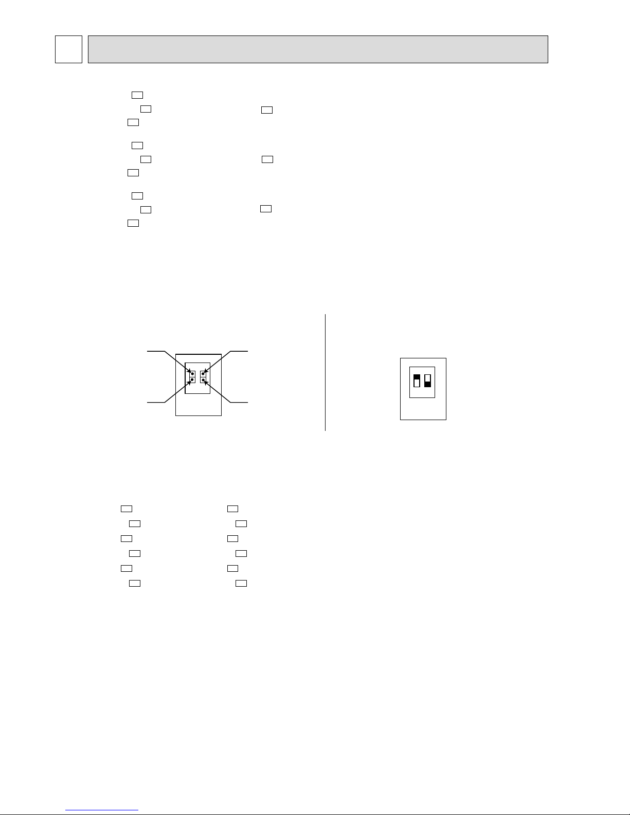
1. Switch SW2 has added on the indoor electronic control P.C. board.
• Indoor unit model has changed. Indoor units for COOL only type (MU and MUX) and COOL and HEAT type (MUH and
MXZ)are common specifications. Set switch SW2-2
according to the type of outdoor unit.
• Change switch SW2-1 for setting AUTO RESTART FUNCTION ON/OFF.
E1
E1
E1
E1
E1
E1
E1
E1
E1
1
}
➔ MSC-07RV -
E1
}
➔ MSC-09RV -
E1
}
➔ MSC-12RV -
E1
1 2
SW2
1 2
AUTO RESTART
FUNCTION :OFF
AUTO RESTART
FUNCTION :ON
OUTDOOR UNIT
MU & MUX type
OUTDOOR UNIT
MUH & MXZ type
Set of switch SW2
1 2
SW2
1 2
When the units are shipped from the factory,
switch SW2 is as follows.
SW2-1: AUTO RESTART FUNCTION OFF
SW2-2: MUH type
2. SLEEP MODE function has been removed.
3. ECONO COOL operation has been added.
4. SWING button is removed, but SWING MODE function is available by VANE CONTROLbutton.
MU-07NV - ➔ MU-07RV MUH-07NV - ➔ MUH-07RV MU-09NV - ➔ MU-09RV MUH-09NV - ➔ MUH-09RV MU-12NV - ➔ MU-12RV MUH-12NV - ➔ MUH-12RV -
1. Outdoor model has changed.
E1E2
E1E2
E1E2
E1E2
E1E2
E1E2
Page 3
3
MUX-10NV - ➔ MUX-10RV -
1.Outdoor model name has changed.
2 Refrigerant filling capacity has changed. (1.15kg ➔ 1.0kg)
MUX-18NV - ➔ MUX-18RV -
1.Outdoor model name has changed.
2 Capillary tube has changed.
([3.0O[1.4O1000 ➔ [3.0O[1.4O1100)
([3.0O[1.4O600 ➔ [3.0O[1.6O1100)
([3.0O[1.4O150 ➔ [3.0O[1.6O300)
MUX-24NV - ➔ MUX-24RV -
1.Outdoor model name has changed.
2 Refrigerant filling capacity has changed. (1.15+1.15kg ➔ 1.0+1.0kg))
MXZ-18NV - ➔ MXZ-18RV -
1.Outdoor model name has changed.
2.Possibly connected indoor units combination was changed.
(MSH-09NV(2) - O2 ➔ MSC-09RV - O2)
(MSH-07NV(2) - + MSH-12NV(2) - ➔ MSC-07RV - + MSC-12RV - )
MXZ-32NV - ➔ MXZ-32RV -
1.Outdoor model name has changed.
2.Possibly connected indoor units were changed.
(MSH-07NV(2) - ➔ MSC-07RV - )
(MSH-09NV(2) - ➔ MSC-09RV - )
(MSH-12NV(2) - ➔ MSC-12RV - )
(MSH-18NV - ➔ MSH-18NV - )
3.Control P.C. board has changed.
4.Compressor frequency controll has partly changed.
E4E3
E1E2
E1E2
E1E2
E1E2
E1E1E2E2
E1E2
E1E2
E1E1
E1E1
E1E1
Page 4
4
PART NAMES AND FUNCTIONS
2
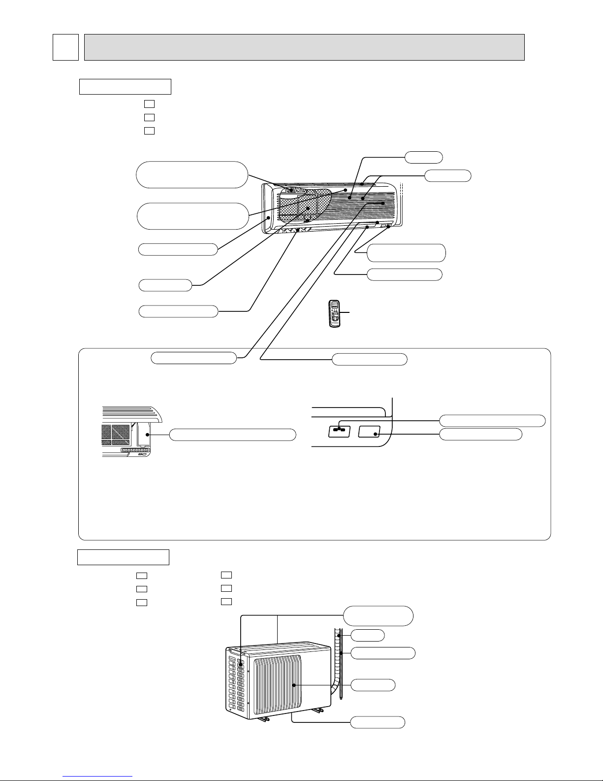
INDOOR UNIT
MSC-07RV MSC-09RV MSC-12RV -
E1
E1
E1
Emergency operation switch
Operation section
Horizontal vane
Air filter
Deodorizing filter
(gray sponge type)
Vertical vanes
Air inlet
Grille
Remote control
receiving section
Remote controller
Display section
(when the front grille is open)
Operation indicator lamp
Receiving section
Air cleaning filter
(white bellows type)
Front panel
Air inlet
Piping
Drain hose
Air outlet
Drain outlet
(back and side)
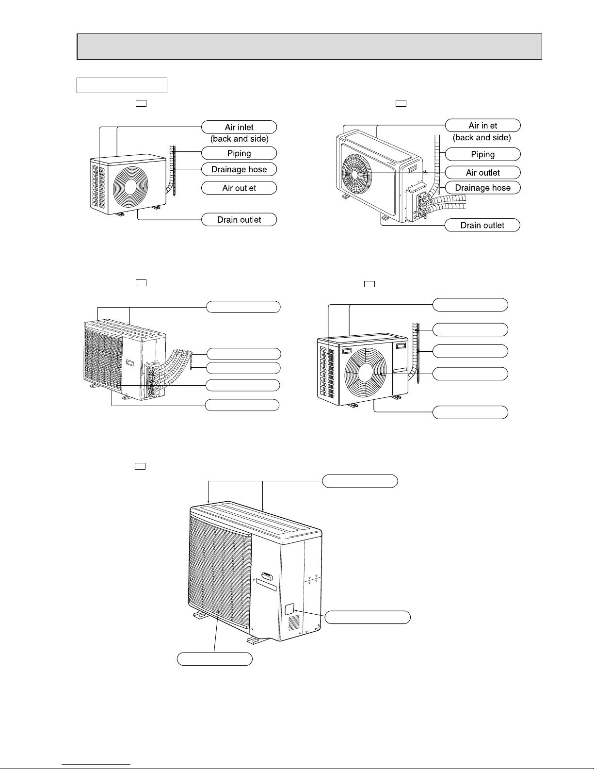
OUTDOOR UNIT
MU-07RV -
MU-09RV MU-12RV -
E1
E1
E1
MUH-07RV MUH-09RV MUH-12RV -
E1
E1
E1
Page 5
5
OUTDOOR UNIT
MUX-10RV-
E1
MUX-24RV-
E1
Air inlet
(back and side)
Piping
Drainage hose
Air outlet
Drain outlet
Air inlet
Air outlet
(back and side)
Model indication
Air inlet
Piping
Air outlet
Drain outlet
Drainage hose
(back and side)
MXZ-18RV-
E1
MXZ-32RV-
E1
MUX-18RV-
E1
Page 6
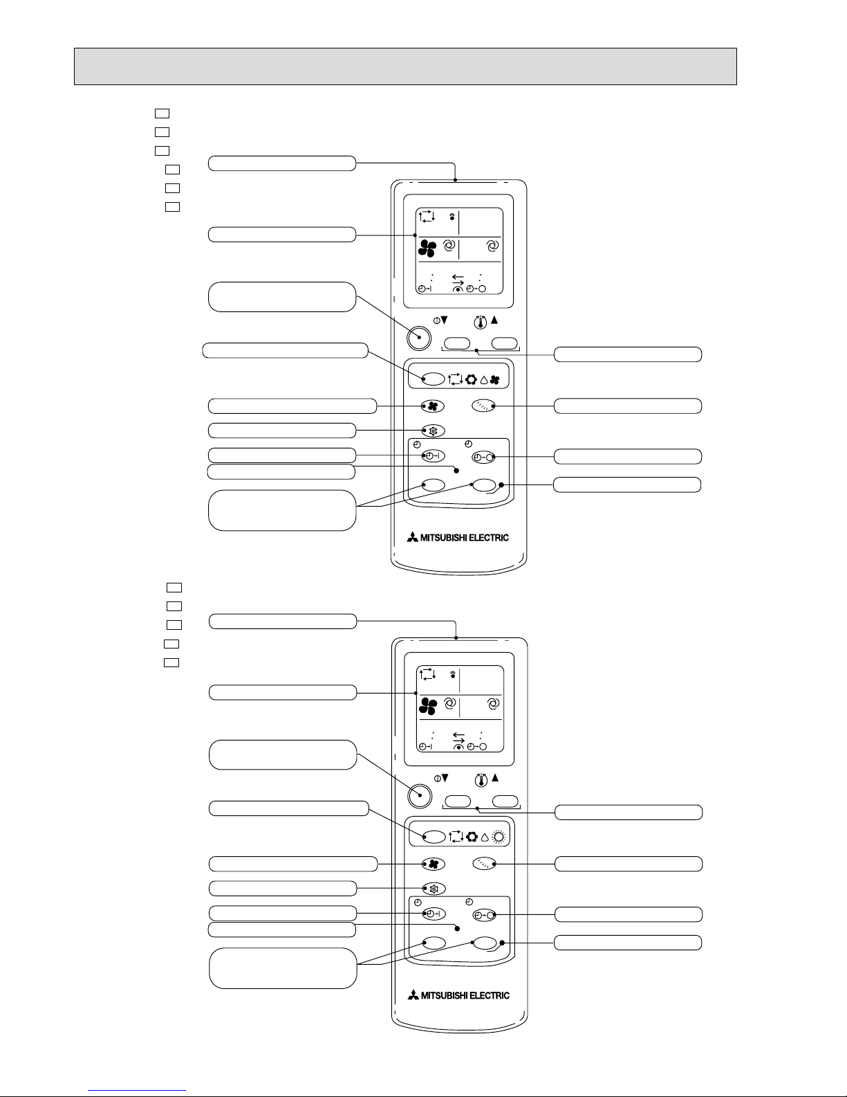
6
Signal transmitting section
Operation display section
OPERATE /STOP
(ON /OFF)button
OPERATION SELECT button
FAN SPEED CONTROL button
ECONO COOL button
ON-TIMER button
CLOCK SET button
HR. button
MIN. button
(TIME SET button)
TEMPERATURE buttons
VANE CONTROL button
OFF-TIMER button
RESET button
ON/OFF TOO
WARM
TOO
COOL
HR. MIN.
CLOCK
RESET
CLOCK
6 00
1 1 00
MODE
FAN
VANE
START
STOP
ECONO COOL
AM
PM
I FEEL
COOL DRY FAN
MU-07RV MU-09RV MU-12RV MUX-10RV MUX-18RV MUX-24RV -
E1
E1
E1
E1
E1
E1
MUH-07RV MUH-09RV MUH-12RV MXZ-18RV MXZ-32RV -
E1
E1
E1
E1
E1
Signal transmitting section
Operation display section
OPERATE /STOP
(ON /OFF)button
OPERATION SELECT button
FAN SPEED CONTROL button
ON-TIMER button
CLOCK SET button
HR. button
MIN. button
(TIME SET button)
TEMPERATURE buttons
VANE CONTROL button
OFF-TIMER button
RESET button
ON/OFF TOO
WARM
TOO
COOL
HR. MIN.
CLOCK
RESET
CLOCK
MODE
FAN
VANE
START
STOP
ECONO COOL button
ECONO COOL
I FEEL
COOL DRY HEAT
6 00
1
1 00
AM
PM
WThe remote controller is packed with the outdoor unit (MU& MUH type).
WThe remote controller is packed with the outdoor unit (MUH& MXZ type).
Page 7
7
3
INDOOR / OUTDOOR CORRESPONDENCE TABLE
❈There is no combination other than this table.
MXZ-32RV- E1
MXZ-18RV- E1
OUTDOOR UNIT
Combination of the connectable indoor units
07+07+07
07+07+09
07+07+(12 or 13)
07+07+18
07+09+09
07+09+(12 or 13)
07+09+18
07+(12 or 13)+(12 or 13)
07+(12 or 13)+18
07+18+18
09+09+09
09+09+(12 or 13)
09+09+18
09+(12 or 13)+(12 or 13)
09+(12 or 13)+18
09+18+18
(12 or 13)+(12 or 13)+(12 or 13)
(12 or 13)+(12 or 13)+18
07+07+07+07
07+07+07+09
07+07+07+(12 or 13)
07+07+07+18
07+07+09+09
07+07+09+(12 or 13)
07+07+09+18
07+07+(12 or 13)+(12 or 13)
07+07+(12 or 13)+18
07+09+09+09
07+09+09+(12 or 13)
07+09+09+18
07+09+(12 or 13)+(12 or 13)
09+09+09+09
09+09+09+(12 or 13)
09+09+09+18
09+09+(12 or 13)+(12 or 13)
OUTDOOR UNIT
09+09
07+12
MXZ-18RV
MXZ-32RV
Page 8
8
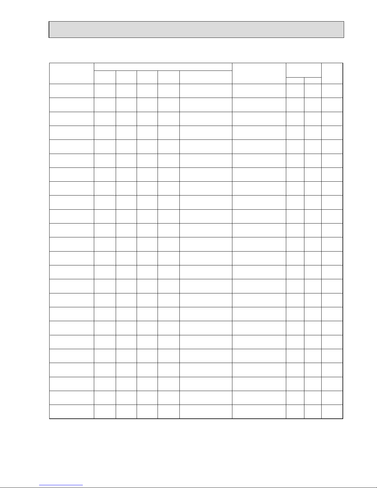
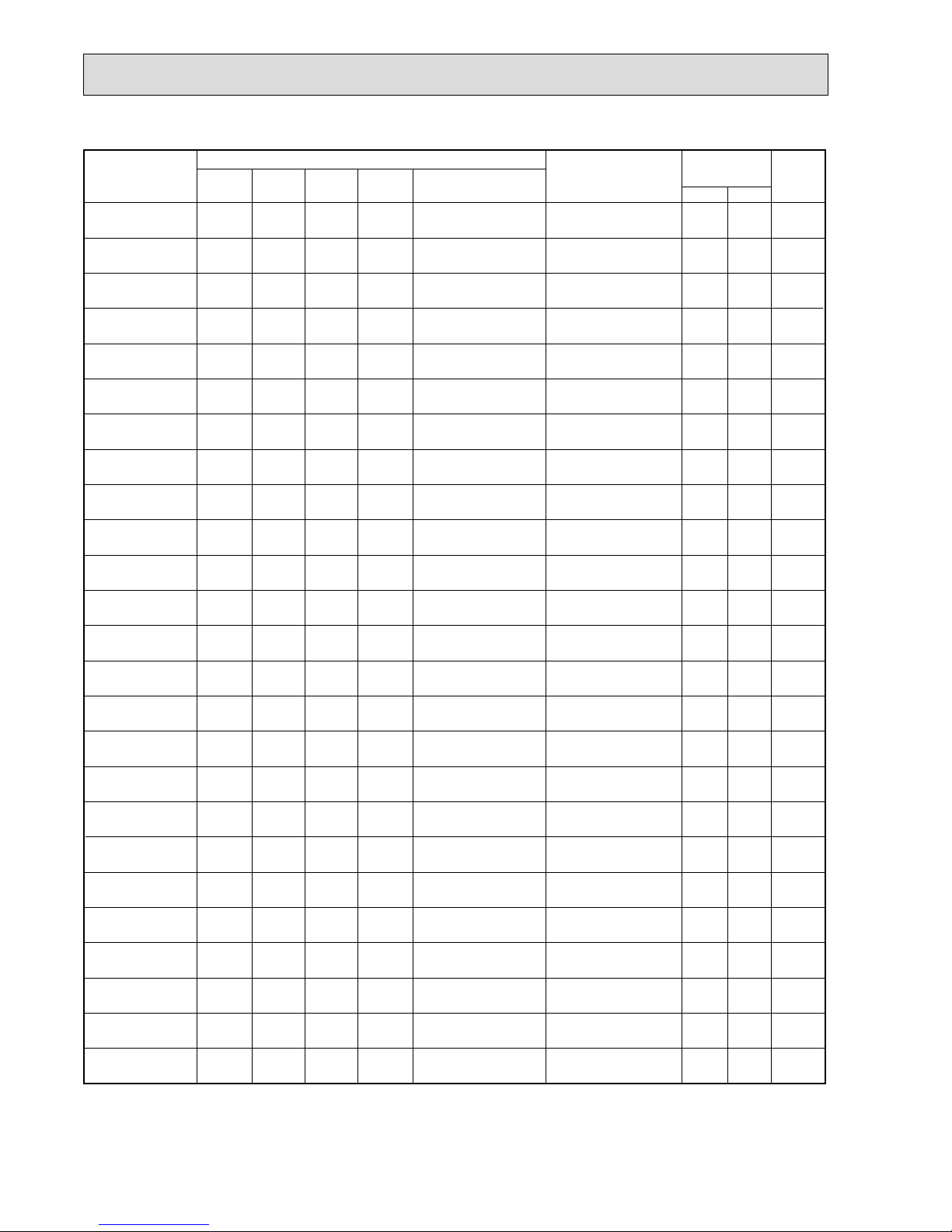
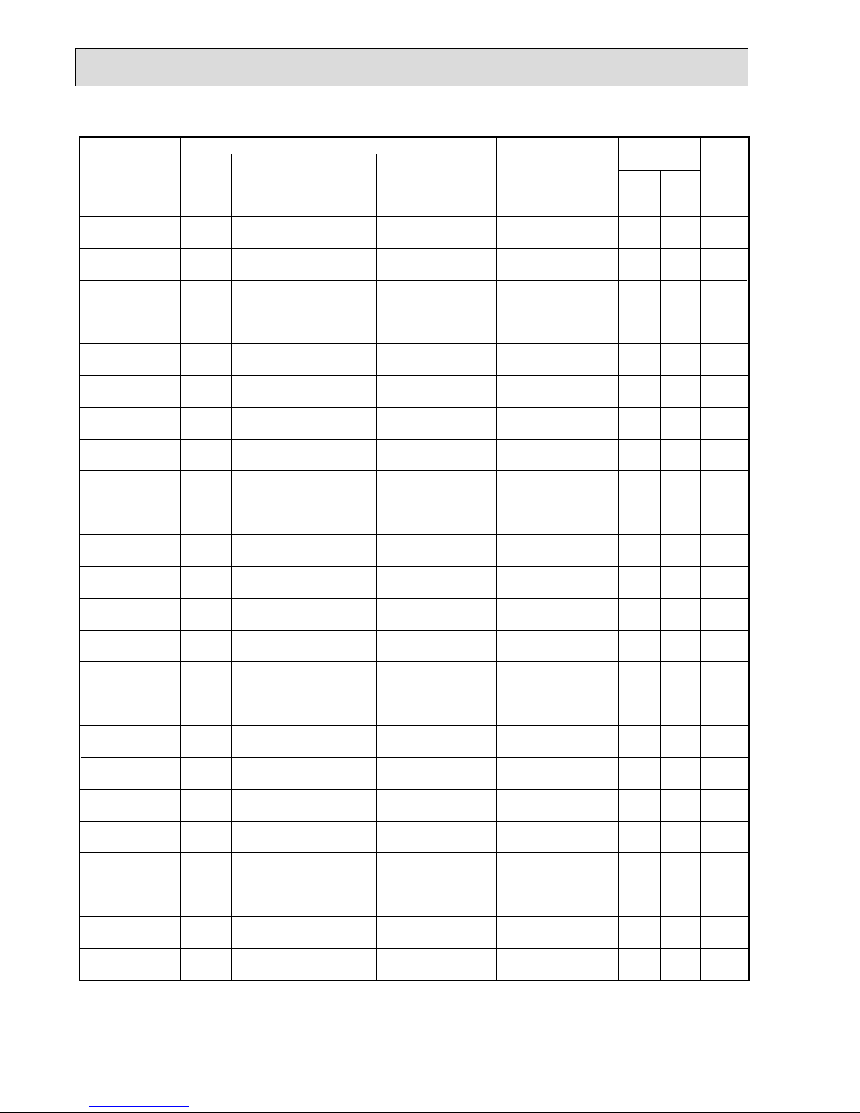
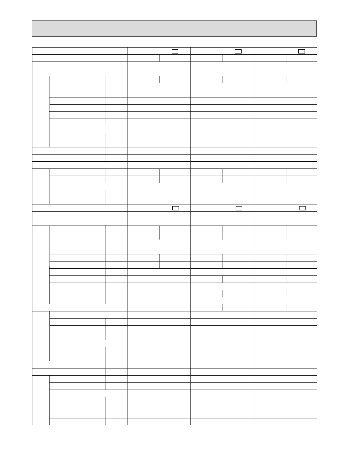
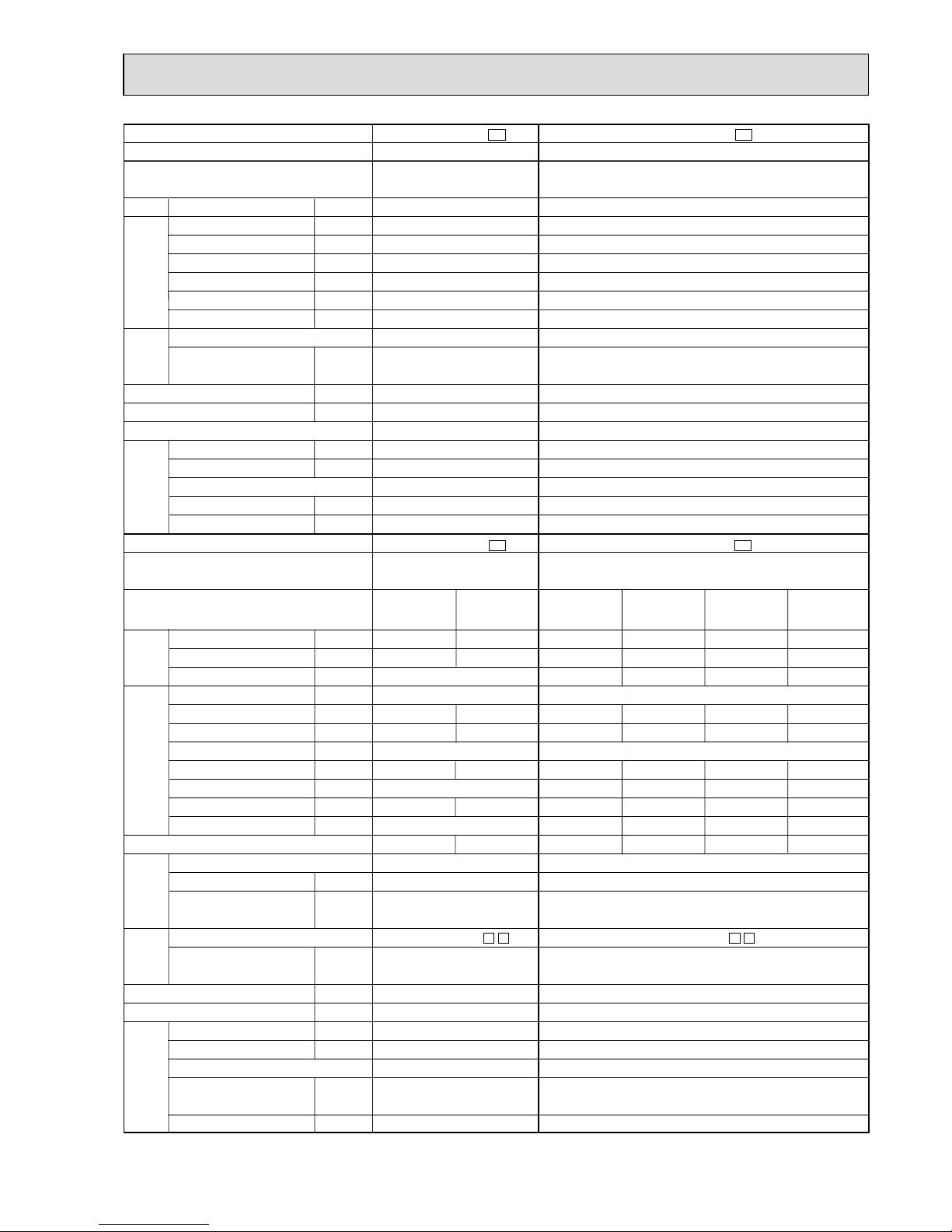
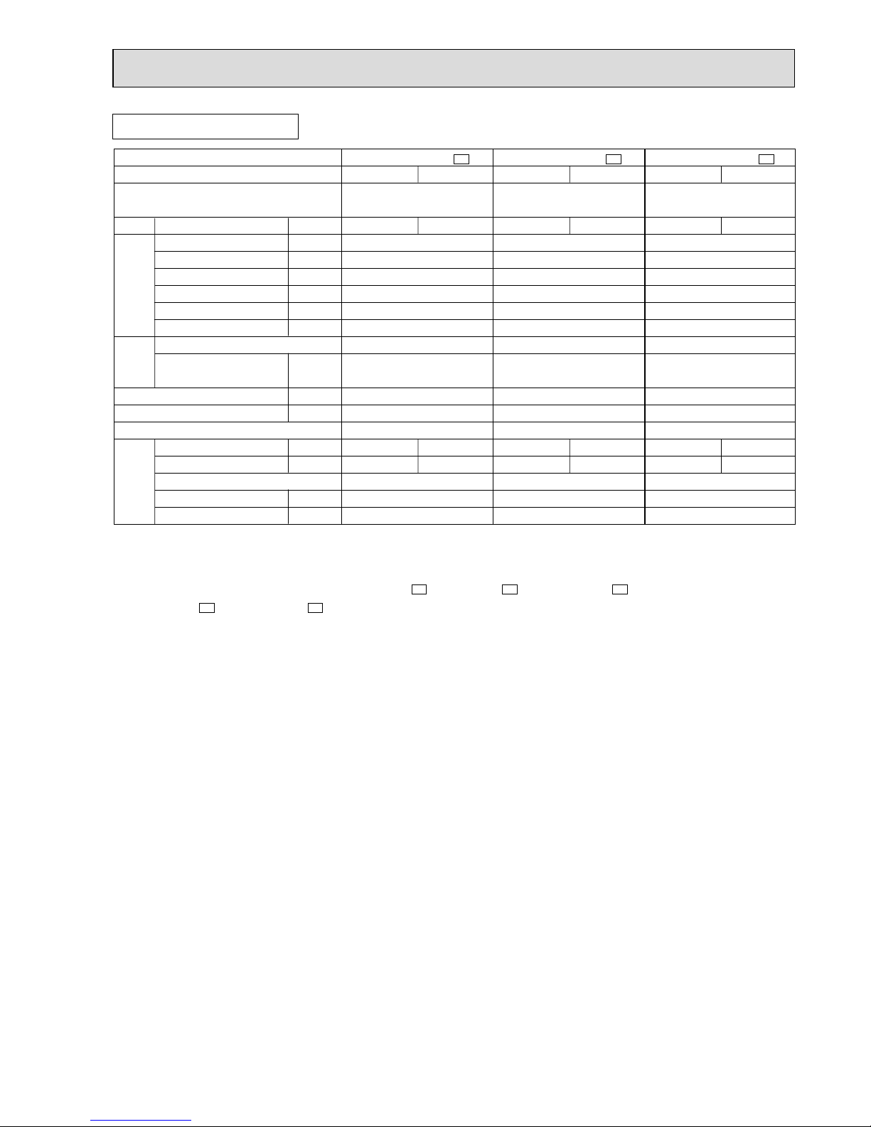
INDOOR UNITS COMBINATION
4
Outdoor unit
power consumption
(kW)
07
09
12
07+12
09+09
Indoor units
combination
Unit B
Unit A
Cooling capacity (kW)
Total
220V 240V
Current
(A)
Power
factor
(%)
2.3
2.5
3.4
2.0
2.25
-
-
-
2.5
2.25
2.3
(1.6 - 2.8)
2.5
(1.7 - 3.0)
3.4
(1.8 - 3.8)
4.5
(2.0 - 4.5)
4.5
(1.9 - 4.5)
1.02
(0.855 - 1.33)
1.05
(0.855 - 1.36)
1.45
(0.855 - 1.63)
2.00
(0.91- 2.00)
2.00
(0.91 - 2.00)
5.20
5.36
7.40
10.21
10.21
89 - 90
89 - 90
89 - 90
89 - 90
89 - 90
4.72
4.86
6.71
9.26
9.26
Outdoor unit
power consumption
(kW)
07
09
12
07+12
09+09
Indoor units
combination
Unit B
Unit A
Heating capacity (kW)
Total
220V 240V
Current
(A)
Power
factor
(%)
3.3
3.6
4.0
2.7
2.9
-
-
-
3.1
2.9
3.3
(2.0 - 4.0)
3.6
(2.0 - 4.5)
4.0
(2.2 - 4.7)
5.8
(2.1 - 5.8)
5.8
(2.0 - 5.8)
1.45
(0.69 - 1.60)
1.47
(0.69 - 1.62)
1.63
(0.69 - 1.69)
1.785
(0.69 - 1.785)
1.785
(0.69 - 1.785)
7.40
7.50
8.32
9.02
9.02
89 - 90
89 - 90
89 - 90
90 - 90
90 - 90
6.71
6.80
7.54
8.26
8.26
MXZ-18RV
NOTE:Electrical data is for outdoor unit only.
Page 9
9
07
09
12(13)
18
07+07
07+09
07+12(13)
07+18
09+09
09+12(13)
09+18
12(13)+12(13)
12(13)+18
18+18
07+07+07
07+07+09
07+07+12(13)
07+07+18
07+09+09
07+09+12(13)
07+09+18
07+12(13)+12(13)
07+12(13)+18
07+18+18
90
90
90
90
90
90
90
90
90
90
90
90
90
90
90
90
90
90
90
90
90
90
90
90
4.63
5.42
6.57
8.52
7.55
8.70
11.02
12.69
9.86
12.18
15.65
15.65
15.65
15.65
14.95
14.95
14.95
14.95
14.95
14.95
14.95
14.95
14.95
14.95
5.05
5.91
7.17
9.29
8.23
9.49
12.02
13.84
10.76
13.28
17.07
17.07
17.07
17.07
16.31
16.31
16.31
16.31
16.31
16.31
16.31
16.31
16.31
16.31
2.2
(1.8-2.7)
2.8
(1.8-3.2)
4.0
(2.2-4.5)
5.0
(2.2-5.4)
4.4
(3.0-5.4)
5.0
(3.0-6.0)
6.2
(3.0-7.2)
7.2
(3.0-7.6)
5.6
(3.0-6.4)
6.8
(3.0-7.6)
7.8
(3.0-8.6)
8.0
(3.0-8.8)
8.0
(3.0-8.8)
8.0
(3.0-8.8)
6.6
(3.7-8.1)
7.2
(3.7-8.5)
8.0
(3.7-9.0)
8.0
(3.7-9.0)
7.8
(3.7-8.8)
8.0
(3.7-9.0)
8.0
(3.7-9.0)
8.0
(3.7-9.0)
8.0
(3.7-9.0)
8.0
(3.7-9.0)
1.00
(0.96-1.14)
1.77
(0.96-1.36)
1.42
(1.00-1.63)
1.84
(1.00-1.99)
1.63
(1.30-2.03)
1.88
(1.30-2.23)
2.38
(1.30-3.60)
2.74
(1.30-3.60)
2.13
(1.30-3.60)
2.63
(1.30-3.60)
3.29
(1.30-3.60)
3.38
(1.30-3.60)
3.38
(1.30-3.60)
3.38
(1.30-3.60)
3.23
(1.30-3.96)
3.23
(1.30-3.96)
3.23
(1.30-3.96)
3.23
(1.30-3.96)
3.23
(1.30-3.96)
3.23
(1.30-3.96)
3.23
(1.30-3.96)
3.23
(1.30-3.96)
3.23
(1.30-3.96)
3.23
(1.30-3.96)
-
-
-
-
-
-
-
-
-
-
-
-
-
-
-
-
-
-
-
-
-
-
-
-
-
-
-
-
-
-
-
-
-
-
-
-
-
-
2.2
2.8
3.8
4.2
2.8
3.6
4.0
3.1
3.6
3.25
-
-
-
-
2.2
2.8
4.0
5.0
2.8
4.0
5.0
4.0
4.5
4.0
2.2
2.2
2.1
1.9
2.8
2.5
2.3
3.1
2.8
3.25
2.2
2.8
4.0
5.0
2.2
2.2
2.2
2.2
2.8
2.8
2.8
4.0
3.5
4.0
2.2
2.2
2.1
1.9
2.2
1.9
1.7
1.8
1.6
1.5
Indoor units
combination
Unit A Unit B Unit C Unit D
Cooling capacity (kw)
Total
Outdoor unit
power consumption
(kw)
Current
(A)
Power
factor
(%)
220V 240V
NOTE: Electrical data is for outdoor unit only.
MXZ-32RV
Page 10
10
Indoor units
combination
Unit A Unit B Unit C Unit D
Cooling capacity (kw)
Total
Outdoor unit
power consumption
(kw)
Current
(A)
Power
factor
(%)
220V 240V
90
90
90
90
90
90
90
90
90
90
90
90
90
90
90
90
90
90
90
90
90
90
90
90
90
14.92
14.95
14.95
14.95
14.95
14.95
14.95
14.95
14.95
14.95
14.95
14.95
14.95
14.95
14.95
14.95
14.95
14.95
14.95
14.95
14.95
14.95
14.95
14.95
14.95
16.31
16.31
16.31
16.31
16.31
16.31
16.31
16.31
16.31
16.31
16.31
16.31
16.31
16.31
16.31
16.31
16.31
16.31
16.31
16.31
16.31
16.31
16.31
16.31
16.31
8.0
(3.7-9.0)
8.0
(3.7-9.0)
8.0
(3.7-9.0)
8.0
(3.7-9.0)
8.0
(3.7-9.0)
8.0
(3.7-9.0)
8.0
(3.7-9.0)
8.0
(3.7-9.0)
8.0
(3.7-9.0)
7.9
(3.7-9.0)
8.0
(3.7-9.0)
8.0
(3.7-9.0)
8.0
(3.7-9.0)
8.0
(3.7-9.0)
8.0
(3.7-9.0)
8.0
(3.7-9.0)
8.0
(3.7-9.0)
8.0
(3.7-9.0)
8.0
(3.7-9.0)
8.0
(3.7-9.0)
8.0
(3.7-9.0)
8.0
(3.7-9.0)
8.0
(3.7-9.0)
8.0
(3.7-9.0)
8.0
(3.7-9.0)
3.23
(1.30-3.96)
3.23
(1.30-3.96)
3.23
(1.30-3.96)
3.23
(1.30-3.96)
3.23
(1.30-3.96)
3.23
(1.30-3.96)
3.23
(1.30-3.96)
3.23
(1.30-3.96)
3.23
(1.30-3.96)
3.23
(1.30-3.96)
3.23
(1.30-3.96)
3.23
(1.30-3.96)
3.23
(1.30-3.96)
3.23
(1.30-3.96)
3.23
(1.30-3.96)
3.23
(1.30-3.96)
3.23
(1.30-3.96)
3.23
(1.30-3.96)
3.23
(1.30-3.96)
3.23
(1.30-3.96)
3.23
(1.30-3.96)
3.23
(1.30-3.96)
3.23
(1.30-3.96)
3.23
(1.30-3.96)
3.23
(1.30-3.96)
-
-
-
-
-
-
-
-
2.0
2.4
2.9
3.5
2.2
2.8
3.2
2.6
3.0
2.1
2.7
3.1
2.45
2.0
2.6
3.0
2.35
2.67
3.4
3.8
3.0
3.4
3.1
2.67
3.1
2.0
1.83
1.7
1.5
2.2
2.0
1.8
2.6
2.4
2.1
1.9
1.75
2.45
2.0
1.8
1.67
2.35
2.67
2.3
2.1
2.0
1.9
1.8
2.67
2.45
2.0
1.83
1.7
1.5
1.8
1.6
1.5
1.4
1.3
1.7
1.5
1.4
1.35
2.0
1.8
1.67
1.65
2.67
2.3
2.1
3.0
2.7
3.1
2.67
2.45
2.0
1.83
1.7
1.5
1.8
1.6
1.5
1.4
1.3
2.1
1.9
1.75
1.75
2.0
1.8
1.67
1.65
09+09+09
09+09+12(13)
09+09+18
09+12(13)+12(13)
09+12(13)+18
09+18+18
12(13)+12(13)
+12(13)
12(13)+12(13)+18
07+07+07+07
07+07+07+09
07+07+07+12(13)
07+07+07+18
07+07+09+09
07+07+09+12(13)
07+07+09+18
07+07+12(13)
+12(13)
07+07+12(13)+18
07+09+09+09
07+09+09+12(13)
07+09+09+18
07+09+12(13)
+12(13)
09+09+09+09
09+09+09+12(13)
09+09+09+18
09+09+12(13)
+12(13)
NOTE: Electrical data is for outdoor unit only.
Page 11

11
NOTE: Electrical data is for outdoor unit only.
07
09
12(13)
18
07+07
07+09
07+12(13)
07+18
09+09
09+12(13)
09+18
12(13)+12(13)
12(13)+18
18+18
07+07+07
07+07+09
07+07+12(13)
07+07+18
07+09+09
07+09+12(13)
07+09+18
07+12(13)+12(13)
07+12(13)+18
07+18+18
90
90
90
90
90
90
90
90
90
90
90
90
90
90
90
90
90
90
90
90
90
90
90
90
5.55
6.62
8.29
9.72
9.17
10.32
13.05
13.05
11.01
13.05
13.05
13.05
13.05
13.05
12.87
12.87
12.87
12.87
12.87
12.87
12.87
12.87
12.87
12.87
6.06
7.22
9.04
10.61
10.00
11.26
14.24
14.24
12.02
14.24
14.24
14.24
14.24
14.24
14.04
14.04
14.04
14.04
14.04
14.04
14.04
14.04
14.04
14.04
3.4
(2.1-3.6)
4.0
(2.1-4.2)
6.0
(2.2-6.3)
7.1
(2.2-7.5)
6.8
(4.1-7.2)
7.4
(4.1-7.8)
9.3
(4.1-9.7)
9.3
(4.1-9.7)
8.0
(4.1-8.4)
9.3
(4.1-9.7)
9.3
(4.1-9.7)
9.3
(4.1-9.7)
9.3
(4.1-9.7)
9.3
(4.1-9.7)
9.3
(5.2-10.6)
9.3
(5.2-10.6)
9.3
(5.2-10.6)
9.3
(5.2-10.6)
9.3
(5.2-10.6)
9.3
(5.2-10.6)
9.3
(5.2-10.6)
9.3
(5.2-10.6)
9.3
(5.2-10.6)
9.3
(5.2-10.6)
1.20
(0.91-1.28)
1.43
(0.91-1.51)
1.79
(0.94-1.88)
2.10
(0.94-2.21)
1.98
(1.13-2.18)
2.23
(1.13-2.33)
2.82
(1.13-2.96)
2.82
(1.13-2.96)
2.38
(1.13-2.54)
2.82
(1.13-2.96)
2.82
(1.13-2.96)
2.82
(1.13-2.96)
2.82
(1.13-2.96)
2.82
(1.13-2.96)
2.78
(1.19-2.96)
2.78
(1.19-2.96)
2.78
(1.19-2.96)
2.78
(1.19-2.96)
2.78
(1.19-2.96)
2.78
(1.19-2.96)
2.78
(1.19-2.96)
2.78
(1.19-2.96)
2.78
(1.19-2.96)
2.78
(1.19-2.96)
-
-
-
-
-
-
-
-
-
-
-
-
-
-
-
-
-
-
-
-
-
-
-
-
-
-
-
-
-
-
-
-
-
-
-
-
-
-
3.1
3.4
4.3
4.7
3.25
4.1
4.5
3.65
4.0
3.75
-
-
-
-
3.4
4.0
5.95
6.45
4.0
5.6
5.95
4.65
5.0
4.65
3.1
2.95
2.5
2.3
3.25
2.8
2.6
3.65
3.4
3.75
3.4
4.0
6.0
7.1
3.4
3.4
3.35
2.85
4.0
3.7
3.35
4.65
4.3
4.65
3.1
2.95
2.5
2.3
2.8
2.4
2.2
2.0
1.9
1.8
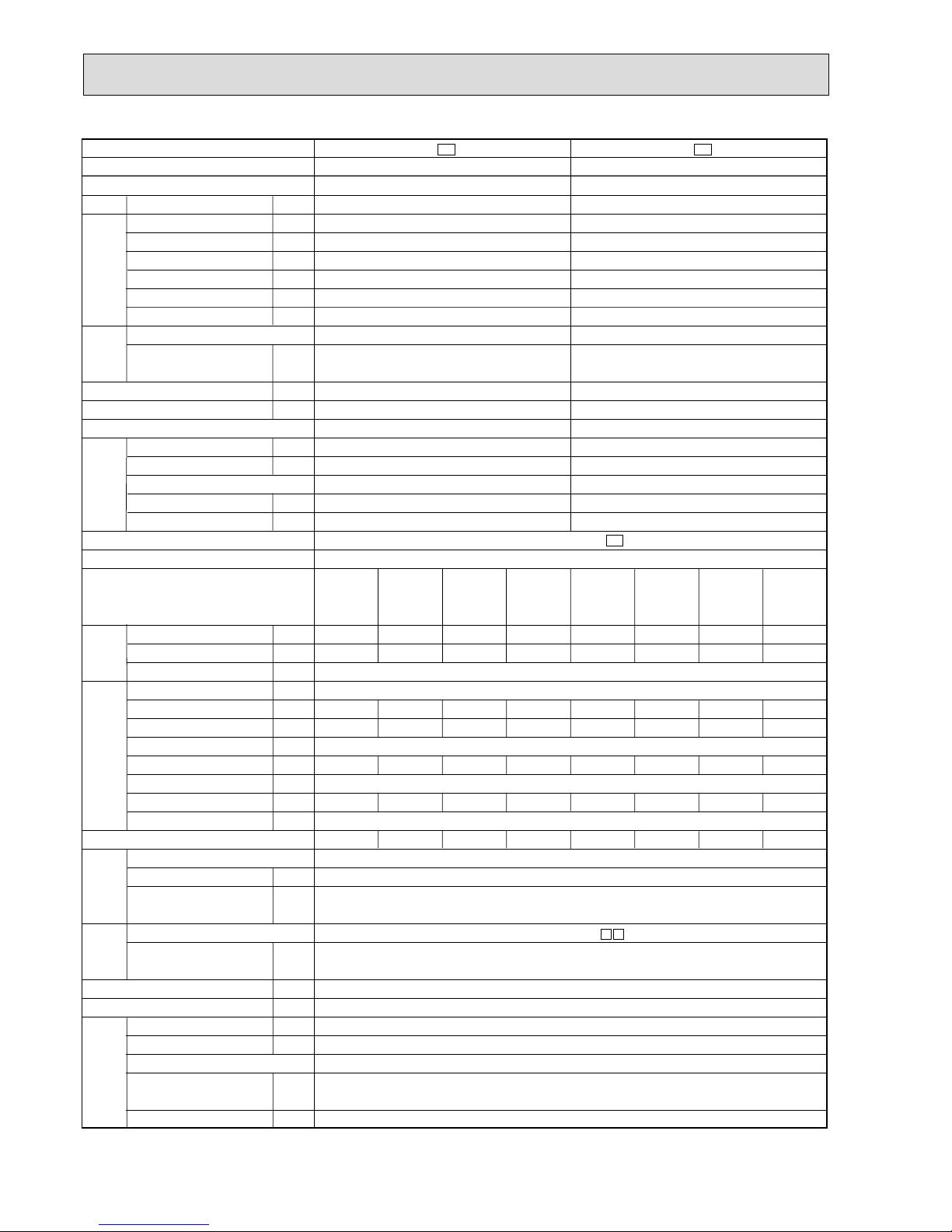
Indoor units
combination
Unit A Unit B Unit C Unit D
Heating capacity (kw)
Total
Outdoor unit
power consumption
(kw)
Current
(A)
Power
factor
(%)
220V 240V
Page 12
12
Indoor units
combination
Unit A Unit B Unit C Unit D
Heating capacity (kw)
Total
Outdoor unit
power consumption
(kw)
Current
(A)
Power
factor
(%)
220V 240V
90
90
90
90
90
90
90
90
90
90
90
90
90
90
90
90
90
90
90
90
90
90
90
90
90
12.87
12.87
12.87
12.87
12.87
12.87
12.87
12.87
12.87
12.87
12.87
12.87
12.87
12.87
12.87
12.87
12.87
12.87
12.87
12.87
12.87
12.87
12.87
12.87
12.87
14.04
14.04
14.04
14.04
14.04
14.04
14.04
14.04
14.04
14.04
14.04
14.04
14.04
14.04
14.04
14.04
14.04
14.04
14.04
14.04
14.04
14.04
14.04
14.04
14.04
9.3
(5.2-10.6)
9.3
(5.2-10.6)
9.3
(5.2-10.6)
9.3
(5.2-10.6)
9.3
(5.2-10.6)
9.3
(5.2-10.6)
9.3
(5.2-10.6)
9.2
(5.2-10.6)
9.3
(6.1-10.6)
9.3
(6.1-10.6)
9.3
(6.1-10.6)
9.3
(6.1-10.6)
9.3
(6.1-10.6)
9.3
(6.1-10.6)
9.3
(6.1-10.6)
9.3
(6.1-10.6)
9.3
(6.1-10.6)
9.3
(6.1-10.6)
9.3
(6.1-10.6)
9.3
(6.1-10.6)
9.3
(6.1-10.6)
9.3
(6.1-10.6)
9.3
(6.1-10.6)
9.3
(6.1-10.6)
9.3
(6.1-10.6)
2.78
(1.19-2.96)
2.78
(1.19-2.96)
2.78
(1.19-2.96)
2.78
(1.19-2.96)
2.78
(1.19-2.96)
2.78
(1.19-2.96)
2.78
(1.19-2.96)
2.78
(1.19-2.96)
2.78
(1.19-2.96)
2.78
(1.19-2.96)
2.78
(1.19-2.96)
2.78
(1.19-2.96)
2.78
(1.19-2.96)
2.78
(1.19-2.96)
2.78
(1.19-2.96)
2.78
(1.19-2.96)
2.78
(1.19-2.96)
2.78
(1.19-2.96)
2.78
(1.19-2.96)
2.78
(1.19-2.96)
2.78
(1.19-2.96)
2.78
(1.19-2.96)
2.78
(1.19-2.96)
2.78
(1.19-2.96)
2.78
(1.19-2.96)
-
-
-
-
-
-
-
-
2.32
2.7
3.3
3.6
2.5
3.3
3.7
2.95
3.3
2.4
3.2
3.6
2.9
2.32
3.15
3.45
2.8
3.1
4.0
4.4
3.5
3.8
3.65
3.1
3.4
2.32
2.2
2.0
1.9
2.5
2.2
2.1
2.95
2.8
2.4
2.15
2.0
2.9
2.32
2.05
1.95
2.8
3.1
2.65
2.45
3.5
3.3
3.65
3.1
2.9
2.32
2.2
2.0
1.9
2.15
1.9
1.75
1.7
1.6
2.4
2.15
2.0
1.9
2.32
2.05
1.95
1.85
3.1
2.65
2.45
2.3
2.2
2.0
3.1
2.9
2.32
2.2
2.0
1.9
2.15
1.9
1.75
1.7
1.6
2.1
1.8
1.7
1.6
2.32
2.05
1.95
1.85
09+09+09
09+09+12(13)
09+09+18
09+12(13)+12(13)
09+12(13)+18
09+18+18
12(13)+12(13)
+12(13)
12(13)+12(13)+18
07+07+07+07
07+07+07+09
07+07+07+12(13)
07+07+07+18
07+07+09+09
07+07+09+12(13)
07+07+09+18
07+07+12(13)
+12(13)
07+07+12(13)+18
07+09+09+09
07+09+09+12(13)
07+09+09+18
07+09+12(13)
+12(13)
09+09+09+09
09+09+09+12(13)
09+09+09+18
09+09+12(13)
+12(13)
NOTE: Electrical data is for outdoor unit only.
Page 13
13
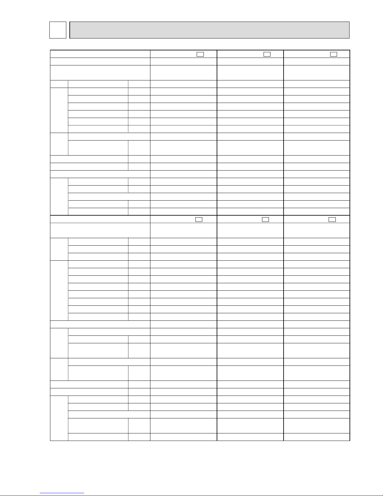
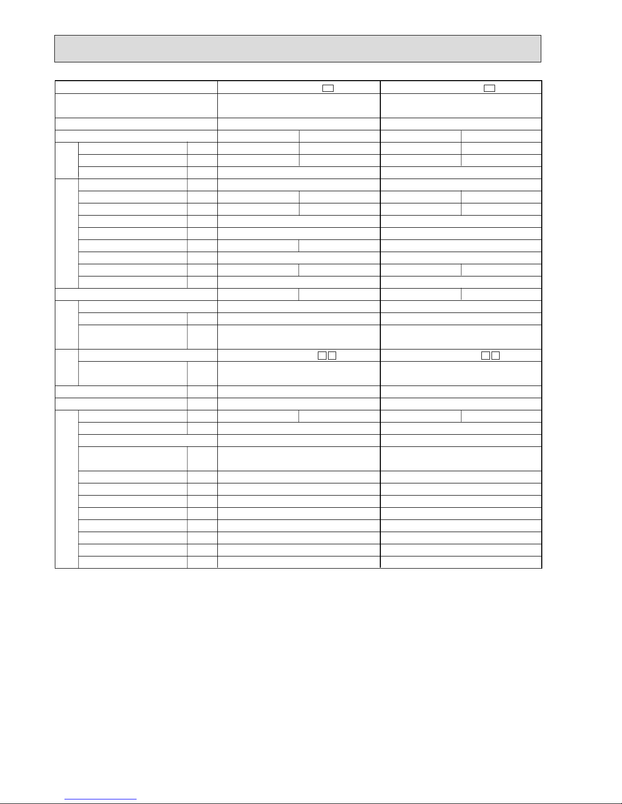
SPECIFICATION
5
Indoor model
Function
Indoor unit power supply
Air flow (Hi)
Power outlet
Running current
Power input
Power factor
Starting current
Fan motor current
Model
Winding
resistance(at20:)
Dimensions WOHOD
Weight
Air direction
Sound level (Hi)
Fan speed (Hi)
Fan speed regulator
Thermistor RT11(at25:)
Thermistor RT12(at25:)
Outdoor model
Capacity
Dehumidification
Outdoor air flow
Power outlet
Running current
Power input
Auxiliary heater
Power factor
Starting current
Compressor motor current
Fan motor current
Model
Output
Winding
resistance(at20:)
Model
Winding
resistance(at20:)
Dimensions WOHOD
Weight
Sound level
Fan speed
Fan speed regulator
Refrigerant filling
capacity(R-22)
Refrigerating oil (Model)
K /h
A
A
W
%
A
A
"
mm
kg
dB
rpm
k"
k"
kW
R/h
K /h
A
A
W
A(kW)
%
A
A
A
W
"
"
mm
kg
dB
rpm
kg
cc
MSC-07RV -
E1
Single phase
220-240V,50Hz
10
0.17
35
93.6-85.8
—
0.17
RC4V19-BA
WHT-BLK 292
BLK-RED 325
850O278O191
9
5
3
10
10
MU-07RV -
E1
Single phase
220-240V,50Hz
10
—
RH-135VGCT
650
C-R 4.18
C-S 5.76
RA6V23-EB
WHT-BLK 258
BLK-RED 385
780o540o255
32
44-45
620-670
1
0.80
300 (MS56 )
Cooling
474
36
950
2.2
0.8
1620-1752
2.98-2.93
645-675
98.4-96.0
19
2.70-2.64
0.28-0.29
3.24-3.10
MSC-09RV -
E1
Single phase
220-240V,50Hz
10
0.17
35
RC4V19-BA
WHT-BLK 292
BLK-RED 325
850O278O191
9
5
3
10
10
MU-09RV -
E1
Single phase
220-240V,50Hz
10
—
RH-145VGCT
700
C-R 4.03
C-S 5.71
RA6V23-EB
WHT-BLK 258
BLK-RED 385
780o540o255
32
44-45
620-670
1
0.85
300 (MS56 )
Cooling
474
93.6-85.8
—
0.17
36
950
2.5
1.1
1620-1752
3.43-3.28
745-775
98.7-98.5
20
3.15-2.99
0.28-0.29
3.21-3.09
MSC-12RV -
E1
Single phase
220-240V,50Hz
10
0.19
40
RC4V19-BA
WHT-BLK 292
BLK-RED 325
850O278O191
10
5
3
10
10
MU-12RV -
E1
Single phase
220-240V,50Hz
1.6
1848-1980
10
—
96.1-91.3
35
5.65-5.78
0.36-0.38
RH-231VHAT
1100
C-R 2.13
C-S 3.91
RA6V33-CB
WHT-BLK 176
BLK-RED 413
780o540o255
34
49
700-750
1
0.88
520 (MS56)
Cooling
588
95.7-87.7
—
0.19
39
1020
3.5
6.01-6.16
1270-1350
2.67-2.52
Electrical
data
Fan
motor
Special
remarks
Compressor
Electrical
data
Fan
motor
Special
remarks
Capacity
Coefficient of performance(C.O.P)
Outdoor unit power supply
Capacity
NOTE:Test conditions Cooling : Indoor DB27°C / WB19°C
Outdoor DB35°C / WB24°C
Page 14
14
Indoor model
Function
Indoor unit power supply
Air flow(Hi)
Power outlet
Running current
Power input
Power factor
Starting current
Fan motor current
Model
Winding
resistance(at20:)
Dimensions WOHOD
Weight
Air direction
Sound level (Hi)
Fan speed (Hi)
Fan speed regulator
Thermistor RT11(at25:)
Thermistor RT12(at25:)
Outdoor model
Capacity
Dehumidification
Outdoor air flow
Power outlet
Running current
Power input
Auxiliary heater
Power factor
Starting current
Compressor motor current
Fan motor current
Model
Output
Winding
resistance(at20:)
Model
Winding
resistance(at20:)
Dimensions WOHOD
Weight
Sound level
Fan speed
Fan speed regulator
Refrigerant filling
capacity(R-22)
Refrigerating oil (Model)
Thermistor
RT61(at0:)
K /h
A
A
W
%
A
A
"
mm
kg
dB
rpm
k"
k"
kW
R/h
K /h
A
A
W
A(kW)
%
A
A
A
W
"
"
mm
kg
dB
rpm
kg
cc
k"
MSC-07RV -
E1
Single phase
220-240V,50Hz
10
0.17
35
93.6-85.8
—
0.17
RC4V19-BA
WHT-BLK 292
BLK-RED 325
850O278O191
9
5
3
10
10
MUH-07RV -
E1
Single phase
220-240V,50Hz
1620-1752
10
—
25
0.28-0.29
RH-135VGHT
650
C-R 4.18
C-S 5.76
RA6V23-EA
WHT-BLK 258
BLK-RED 385
788o540o255
33
47
620-670
1
0.80
300 (MS56)
33.18
Cooling
474
36
950
2.2
0.8
3.13-3.03
675-715
98.0-98.3
2.85-2.74
3.10-2.93
Heating
504
35
1000
2.5
—
2.98-2.88
645-685
98.4-99.1
2.70-2.59
3.68-3.47
MSC-09RV -
E1
Single phase
220-240V,50Hz
10
0.17
35
93.6-85.8
—
0.17
RC4V19-BA
WHT-BLK 292
BLK-RED 325
850O278O191
9
5
3
10
10
MUH-09RV -
E1
Single phase
220-240V,50Hz
1620-1752
10
—
25
0.28-0.29
RH-174VGHT
800
C-R 3.30
C-S 5.80
RA6V23-EA
WHT-BLK 258
BLK-RED 385
780o540o255
33
47
620-670
1
0.80
300 (MS56)
33.18
Cooling
474
36
950
2.5
1.1
3.93-3.83
845-885
97.7-96.3
3.65-3.54
2.84-2.72
Heating
504
35
1000
3.1
—
4.13-3.93
885-905
97.4-95.9
3.85-3.64
3.37-3.30
MSC-12RV -
E1
Single phase
220-240V,50Hz
10
0.19
40
95.7-87.7
—
0.19
RC4V19-BA
WHT-BLK 292
BLK-RED 325
850O278O191
10
5
3
10
10
MUH-12RV -
E1
Single phase
220-240V,50Hz
1656-1758
10
—
35
0.36-0.38
RH-231VHAT
1100
C-R 2.13
C-S 3.91
RA6V33-CA
WHT-BLK 176
BLK-RED 413
780o540o255
38
49
700-740
1
1.19
520 (MS56)
33.18
Cooling
588
39
1020
3.4
1.6
5.56-5.71
1180-1260
96.5-91.9
5.20-5.33
2.79-2.62
Heating
642
39
1100
4.0
—
5.76-5.91
1220-1310
96.3-92.4
5.40-5.53
3.17-2.96
Electrical
data
Fan
motor
Special
remarks
Compressor
Electrical
data
Fan
motor
Special
remarks
Capacity
Coefficient of performance(C.O.P)
Outdoor unit power supply
Capacity
NOTE:Test conditions Cooling : Indoor DB27°C / WB19°C Heating : Indoor DB20°C
Outdoor DB35°C / WB24°C Outdoor DB 7°C / WB 6°C
Page 15
15
Indoor model
Function
Indoor unit power supply
Air flow(Hi)
Power outlet
Running current
Power input
Power factor
Starting current
Fan motor current
Model
Winding
resistance(at20:)
Dimensions WOHOD
Weight
Air direction
Sound level (Hi)
Fan speed (Hi)
Fan speed regulator
Thermistor RT11(at25:)
Thermistor RT12(at25:)
Outdoor model
Capacity
Dehumidification
Outdoor air flow
Power outlet
Running current
Power input
Auxiliary heater
Power factor
Starting current
Compressor motor current
Fan motor current
Model
Output
Winding
resistance(at20:)
Model
Winding
resistance(at20:)
Dimensions WOHOD
Weight
Sound level
Fan speed
Fan speed regulator
Refrigerant filling
capacity(R-22)
Refrigerating oil (Model)
K /h
A
A
W
%
A
A
"
mm
kg
dB
rpm
k"
k"
kW
R/h
K /h
A
A
W
A(kW)
%
A
A
A
W
"
"
mm
kg
dB
rpm
kg
cc
MSC-07RV -
E1
Cooling
Single phase
220-240V,50Hz
474
10
0.17
35
94-86
—
0.17
RC4V19-BA
WHT-BLK 292
BLK-RED 325
850O278O191
9
5
36
950
3
10
10
MUX-10RV -
E1
Single phase
220-240V,50Hz
1560
10
—
17
0.27
KH-134VLL
650
C-R 4.66
C-S 8.20
RA6V22WHT-BLK 325.0
BLK-RED 393.3
760o540o230
31
46-47
700
1
1.0
270 (MS56)
Single
A or B
2.2
0.8
3.33-3.43
705-755
96.0-92.0
3.06-3.16
2.97-2.78
Double
A+B
1.3o2
0.2o2
3.36-3.46
720-760
97.0-92.0
3.09-3.19
3.29-3.13
MSC-09RV -
E1
Cooling
Single phase
220-240V,50Hz
474
10
0.17
35
94-86
—
0.17
RC4V19-BA
WHT-BLK 292
BLK-RED 325
850O278O191
9
5
36
950
3
10
10
MUX-18RV -
E1
Single phase
220-240V,50Hz
15
—
KH-134VLLo2
650o2
C-R 4.66
C-S 8.20
RA6V50-
WHT-BLK 117.3
BLK-YLW 65.0 YLW-RED 49.6
850o605o290
54
53 (Hi)
830-860 (Hi)
2
0.75+0.75
MC1: 270 (MS56) MC2: 270 (MS56)
Single
A or B or C
2.3
0.9
1320
3.63-3.73
755-795
95.0-89.0
17
3.31-3.41
0.32
2.91-2.77
Double
A+B or A+C
2.1o2
0.8o2
1980
7.06-7.16
1500-1580
97.0-92.0
17o2
6.69-6.79
0.37
2.68-2.55
Double
B+C
1.3o2
0.2o2
1320
3.66-3.76
760-810
94.0-90.0
17
3.34-3.44
0.32
3.13-2.95
Triple
A+B+C
2.1+1.3o2
0.8+0.2o2
1980
7.09-7.19
1495-1585
96.0-92.0
17o2
6.72-6.82
0.37
2.94-2.78
Electrical
data
Fan
motor
Special
remarks
Compressor
Electrical
data
Fan
motor
Special
remarks
Capacity
Coefficient of performance(C.O.P)
Outdoor unit power supply
Indoor unit No.
Capacity
NOTE:Test conditions Cooling : Indoor DB27°C / WB19°C Outdoor DB35°C / WB24°C
Page 16
16
Indoor model
Function
Indoor unit power supply
Air flow(Hi)
Power outlet
Running current
Power input
Power factor
Starting current
Fan motor current
Model
Winding
resistance(at20:)
Dimensions WOHOD
Weight
Air direction
Sound level (Hi)
Fan speed (Hi)
Fan speed regulator
Thermistor RT11(at25:)
Thermistor RT12(at25:)
Outdoor model
Capacity
Dehumidification
Outdoor air flow
Power outlet
Running current
Power input
Auxiliary heater
Power factor
Starting current
Compressor motor current
Fan motor current
Model
Output
Winding
resistance(at20:)
Model
Winding
resistance(at20:)
Dimensions WOHOD
Weight
Sound level
Fan speed
Fan speed regulator
Refrigerant filling
capacity(R-22)
Refrigerating oil (Model)
K /h
A
A
W
%
A
A
"
mm
kg
dB
rpm
k"
k"
kW
R/h
K /h
A
A
kW
A(kW)
%
A
A
A
W
"
"
mm
kg
dB
rpm
kg
cc
MSC-09RV -
E1
(Unit C ,D)
Cooling
Single phase 220-240V,50Hz
474
10
0.17
35
94-86
—
0.17
RC4V19-BA
WHT-BLK 292
BLK-RED 325
850O278O191
9
5
36
950
3
10
10
Single
A or B
3.4
1.6
6.18-5.98
1.32-1.38
97.0-96.0
5.90-5.67
2.51-2.40
Single
C or D
2.6
1.2
4.40-4.30
0.94-0.98
97.0-95.0
4.12-3.99
2.67-2.56
MSC-12RV -
E1
(Unit A ,B)
Cooling
Single phase 220-240V,50Hz
588
10
0.19
40
96-88
—
0.19
RC4V19-BA
WHT-BLK 292
BLK-RED 325
850O278O191
10
5
39
1020
3
10
10
Double
A+B
2.0o2
0.5o2
6.46-6.46
1.38-1.48
97.0-95.0
6.18-6.15
2.74-2.56
Double
C+D
1.7o2
0.3o2
4.60-4.40
0.98-1.02
97.0-97.0
4.32-4.09
3.24-3.12
Double
A+C or A+D
B+C or B+D
3.1+2.3
1.4+0.8
10.78-10.38
2.33-2.40
98.0-96.0
10.50-10.07
2.25-2.19
Triple
A+B+C or
A+B+D
1.95o2+2.2
0.5o2+0.8
11.06-10.56
2.36-2.44
97.0-96.0
10.78-10.25
2.46-2.39
Triple
A+C+D or
B+C+D
2.9+1.55o2
1.3+0.3o2
11.08-10.58
2.37-2.45
97.0-96.0
10.80-10.27
2.42-2.35
Four
A+B+C+D
1.95o2+1.55o2
0.5o2+0.3o2
11.46-10.86
2.44-2.49
97.0-96.0
11.18-10.55
2.70-2.65
Electrical
data
Fan
motor
Special
remarks
Compressor
Electrical
data
Fan
motor
Special
remarks
Capacity
Coefficient of performance(C.O.P)
Outdoor unit power supply
Indoor unit No.
Capacity
MUX-24RV -
E1
Single phase 220-240V,50Hz
2400-2640
25
—
48
0.28-0.31
MC1: RH-231VHA MC2: RH-174VGH
RH-231VHA: 1100 RH-174VGH: 800
RH-231VHA: C-R 2.13 C-S 3.91
RH-174VGH: C-R 3.30 C-S 5.80
RA6V25WHT-BLK 142.0
BLK-RED 135.0
900o750o330
71
49
530-570
1
1.0+1.0
MC1: 520 (MS56) MC2: 300 (MS56)
NOTE:Test conditions
Cooling : Indoor DB27°C / WB19°C Outdoor DB35°C / WB24°C
Page 17
17
Indoor model
Function
Indoor unit power supply
Air flow(Hi)
Power outlet
Running current
Power input
Power factor
Starting current
Fan motor current
Model
Winding
resistance(at20:)
Dimensions WOHOD
Weight
Air direction
Sound level (Hi)
Fan speed (Hi)
Fan speed regulator
Thermistor RT11(at25:)
Thermistor RT12(at25:)
W MSC-07RV -
E1
Single phase
220-240V,50Hz
10
0.17
35
94.0-86.0
—
0.17
RC4V19-BA
WHT-BLK 292
BLK-RED 325
850O278O191
9
5
3
10
10
Cooling
474
36
950
Heating
504
35
1000
W MSC-09RV -
E1
Single phase
220-240V,50Hz
10
0.17
35
94.0-86.0
—
0.17
RC4V19-BA
WHT-BLK 292
BLK-RED 325
850O278O191
9
5
3
10
10
Cooling
474
36
950
Heating
504
35
1000
W MSC-12RV -
E1
Single phase
220-240V,50Hz
10
0.19
40
96.0-88.0
—
0.19
RC4V19-BA
WHT-BLK 292
BLK-RED 325
850O278O191
10
5
3
10
10
Cooling
588
39
1020
Heating
642
39
1100
Electrical
data
Fan
motor
Special
remarks
Capacity
W Refer to the above specification when MSC-07RV - ,MSC-09RV- and MSC-12RV- is connected with
MXZ-18RV- and MXZ-32RV- as inverter controlled multi system units.
E1E1
E1E1E1
For inverter multi system
NOTE:Test conditions Cooling : Indoor DB27°C / WB19°C Heating : Indoor DB20°C
Outdoor DB35°C / WB24°C Outdoor DB 7°C / WB 6°C
Page 18
18
Outdoor model
Indoor unit number
Function
Capacity
Dehumidification
Outdoor air flow
Power outlet
Running current
Power input
Auxiliary heater
Crankcase heater
Power factor
Starting current
Compressor motor current
Fan motor current
Model
Output
Winding
resistance(at20:)
Model
Winding
resistance(at20:)
Dimensions WOHOD
Weight
Sound level (Hi)
Fan speed (Hi)
Fan speed regulator
Refrigerant filling
capacity(R-22)
Refrigerating oil (Model)
Thermistor
RT61
Thermistor
RT62
Thermistor
RT63
Thermistor
RT64
Thermistor
RT65
Thermistor
RT66,67
Thermistor
RT68,69
kW
R/h
K /h
A
A
W
A(kW)
W
%
A
A
A
W
"
"
mm
kg
dB
rpm
kg
cc
k"
k"
k"
k"
k"
k"
k"
MXZ-18RV -
E1
Single phase
220-240V,50Hz
2
2460-2580
25
—
—
10.21-9.26
0.4
RHV-207FEM (ROTARY)
1100
U-V 1.195
V-W 1.195 W-U 1.195
RA6V50-
WHT-BLK 154.0
BLK-YLW 68.0 YLW-RED 35.0
870o650o295 (+30)
56
630-670
2
1.3
570 (MS56)
10.0 (at 25:)
13.4 (at 100:)
7.9 (at 70:)
10.0 (at 25:)
10.0 (at 25:)
10.0 (at 25:)
—
Cooling
4.5 (1.6~4.5)
—
10.21-9.26
2000(855~2000)
89.0-90.0
9.81-8.86
2.25
45
Heating
5.8 (2.0~5.8)
—
9.02-8.26
1785(690~1785)
90.0-90.0
8.62-7.86
3.25
46
Compressor
Electrical
data
Fan
motor
Special
remarks
Capacity
Coefficient of performance(C.O.P)
Outdoor unit power supply
MXZ-32RV -
E1
Single phase
220-240V,50Hz
3 or 4
2400-2640
25
—
25
90.0
16.31-14.95
0.6
CHV-253FAA (SCROLL)
2000
U-V 0.54
V-W 0.54 W-U 0.54
RA6V60-
WHT-BLK 78.7 BLK-YLW 26.9
YLW-BLU 11.7 BLU-RED 83.6
900o900o320 (+35)
84
630-675
3
4.2
1070 (MS-56)
13.4 (at 100:)
10.0 (at 25:)
17.0 (at 50:)
10.0 (at 25:)
10.0 (at 25:)
10.0 (at 25:)
10.0 (at 25:)
Cooling
8.0 (1.8~9.0)
—
16.31-14.95
3230(960~3960)
15.71-14.35
2.48
45-47
Heating
9.3 (2.1~10.6)
—
14.04-12.87
2780(910~2960)
13.44-12.27
3.35
46-48
TEST CONDITIONS COOLING INDOOR DB27.0°C WB19.0°C
OUTDOOR DB35.0°C WB24.0°C
HEATING INDOOR DB20.0°C
OUTDOOR DB 7.0°C WB 6.0°C
✽1 Electrical data is for only outdoor unit.
Page 19
19
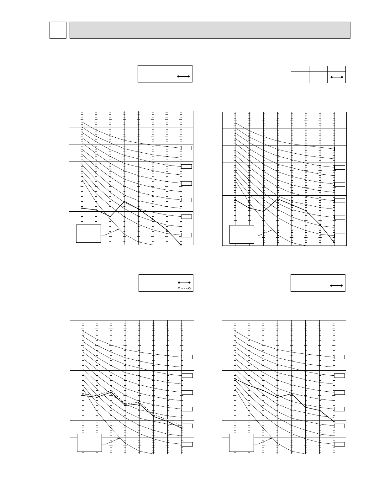
NOISE CRITERIA CURVES6
90
80
70
60
50
40
30
20
10
63 125 250 500 1000 2000 4000 8000
APPROXIMATE
TERESHOLD OF
HEARING FOR
CONTINUOUS
NOISE
NC-60
NC-50
NC-40
NC-30
NC-20
NC-70
OCTAVE BAND SOUND PRESSURE LEVEL, dB re 0.002 MICRO BAR
BAND CENTER FREQUENCIES, Hz
Test conditions.
Cooling : DB27: WB19:
Heating : DB20: WB -:
MSC-07/09RV
Hi
(220/240V)
NOTCH
36
SPL(dB
(A)) LINE
90
80
70
60
50
40
30
20
10
63 125 250 500 1000 2000 4000 8000
APPROXIMATE
TERESHOLD OF
HEARING FOR
CONTINUOUS
NOISE
NC-60
NC-50
NC-40
NC-30
NC-20
NC-70
OCTAVE BAND SOUND PRESSURE LEVEL, dB re 0.002 MICRO BAR
BAND CENTER FREQUENCIES, Hz
Test conditions.
Cooling : DB27: WB19:
Heating : DB20: WB -:
MSC-12RV
Hi
(220/240V)
NOTCH
39
SPL(dB
(A)) LINE
90
80
70
60
50
40
30
20
10
63 125 250 500 1000 2000 4000 8000
APPROXIMATE
TERESHOLD OF
HEARING FOR
CONTINUOUS
NOISE
NC-60
NC-50
NC-40
NC-30
NC-20
NC-70
OCTAVE BAND SOUND PRESSURE LEVEL, dB re 0.002 MICRO BAR
BAND CENTER FREQUENCIES, Hz
Test conditions.
Cooling : DB27: WB19:
MU-07/09RV
HI (220V)
NOTCH
44
HI (240V) 45
SPL(dB
(A)) LINE
90
80
70
60
50
40
30
20
10
63 125 250 500 1000 2000 4000 8000
APPROXIMATE
TERESHOLD OF
HEARING FOR
CONTINUOUS
NOISE
NC-60
NC-50
NC-40
NC-30
NC-20
NC-70
OCTAVE BAND SOUND PRESSURE LEVEL, dB re 0.002 MICRO BAR
BAND CENTER FREQUENCIES, Hz
Test conditions.
Cooling : DB27: WB19:
MU-12RV
Hi
(220/240V)
NOTCH
49
SPL(dB
(A)) LINE
Page 20
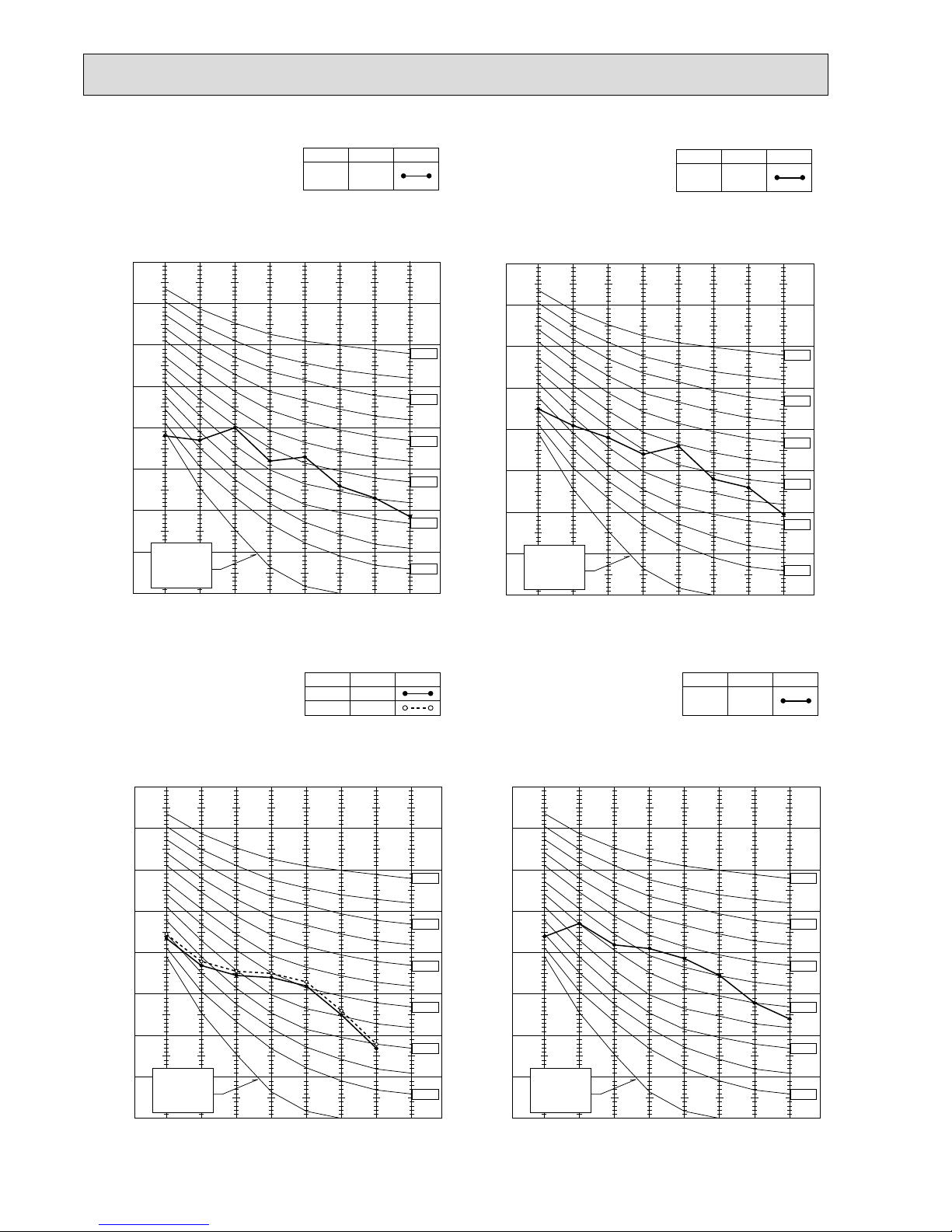
20
90
80
70
60
50
40
30
20
10
63 125 250 500 1000 2000 4000 8000
APPROXIMATE
TERESHOLD OF
HEARING FOR
CONTINUOUS
NOISE
NC-60
NC-50
NC-40
NC-30
NC-20
NC-70
OCTAVE BAND SOUND PRESSURE LEVEL, dB re 0.002 MICRO BAR
BAND CENTER FREQUENCIES, Hz
Test conditions.
Cooling :DB35: WB24:
MUX-10RV
Hi (220V)
NOTCH
46
Hi (240V) 47
SPL(dB
(A)) LINE
90
80
70
60
50
40
30
20
10
63 125 250 500 1000 2000 4000 8000
APPROXIMATE
TERESHOLD OF
HEARING FOR
CONTINUOUS
NOISE
NC-60
NC-50
NC-40
NC-30
NC-20
NC-70
OCTAVE BAND SOUND PRESSURE LEVEL, dB re 0.002 MICRO BAR
BAND CENTER FREQUENCIES, Hz
Test conditions.
Cooling :DB35: WB24:
MUX-18RV
Hi
(220/240V)
NOTCH
53
SPL(dB
(A)) LINE
90
80
70
60
50
40
30
20
10
63 125 250 500 1000 2000 4000 8000
APPROXIMATE
TERESHOLD OF
HEARING FOR
CONTINUOUS
NOISE
NC-60
NC-50
NC-40
NC-30
NC-20
NC-70
OCTAVE BAND SOUND PRESSURE LEVEL, dB re 0.002 MICRO BAR
BAND CENTER FREQUENCIES, Hz
Test conditions.
Cooling :DB35: WB24:
Heating :DB 7: WB 6:
MUH-12RV
Hi
(220/240V)
NOTCH
49
SPL(dB
(A)) LINE
90
80
70
60
50
40
30
20
10
63 125 250 500 1000 2000 4000 8000
APPROXIMATE
TERESHOLD OF
HEARING FOR
CONTINUOUS
NOISE
NC-60
NC-50
NC-40
NC-30
NC-20
NC-70
OCTAVE BAND SOUND PRESSURE LEVEL, dB re 0.002 MICRO BAR
BAND CENTER FREQUENCIES, Hz
Test conditions.
Cooling :DB35: WB24:
Heating :DB 7: WB 6:
MUH-07/09RV
Hi
(220/240V)
NOTCH
47
SPL(dB(A)) LINE
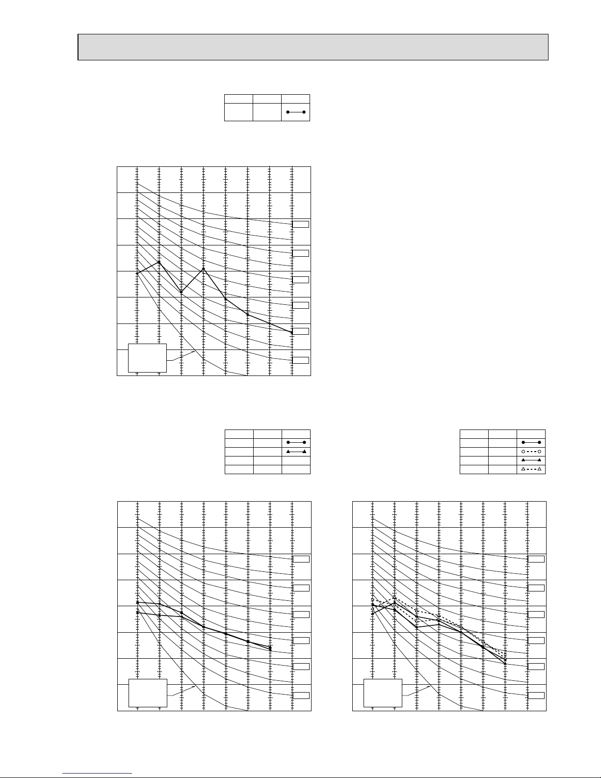
Page 21
21
90
80
70
60
50
40
30
20
10
63 125 250 500 1000 2000 4000 8000
APPROXIMATE
TERESHOLD OF
HEARING FOR
CONTINUOUS
NOISE
NC-60
NC-50
NC-40
NC-30
NC-20
NC-70
OCTAVE BAND SOUND PRESSURE LEVEL, dB re 0.002 MICRO BAR
BAND CENTER FREQUENCIES, Hz
Test conditions.
Cooling :DB35: WB24:
Heating :DB 7: WB 6:
MXZ-18RV
COOL
NOTCH
HEAT
45
SPL(dB
(A))
46
LINE
90
80
70
60
50
40
30
20
10
63 125 250 500 1000 2000 4000 8000
APPROXIMATE
TERESHOLD OF
HEARING FOR
CONTINUOUS
NOISE
NC-60
NC-50
NC-40
NC-30
NC-20
NC-70
OCTAVE BAND SOUND PRESSURE LEVEL, dB re 0.002 MICRO BAR
BAND CENTER FREQUENCIES, Hz
Test conditions.
Cooling :DB35: WB24:
Heating :DB 7: WB 6:
MXZ-32RV
COOL(220V)
NOTCH
COOL(240V)
HEAT(220V)
HEAT(240V)
45
SPL(dB
(A))
47
46
48
LINE
90
80
70
60
50
40
30
20
10
63 125 250 500 1000 2000 4000 8000
APPROXIMATE
TERESHOLD OF
HEARING FOR
CONTINUOUS
NOISE
NC-60
NC-50
NC-40
NC-30
NC-20
NC-70
OCTAVE BAND SOUND PRESSURE LEVEL, dB re 0.002 MICRO BAR
BAND CENTER FREQUENCIES, Hz
Test conditions.
Cooling :DB35: WB24:
MUX-24RV
Hi
(220/240V)
NOTCH
49
SPL(dB
(A)) LINE
Page 22

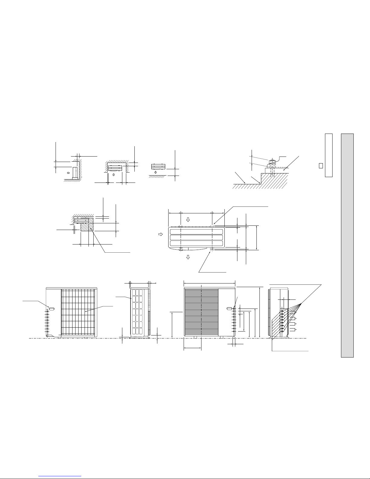
22
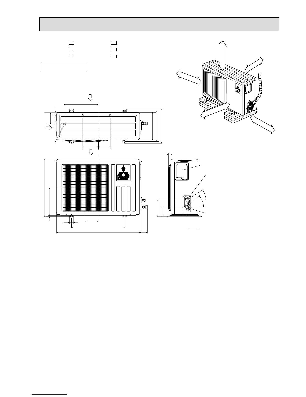
OUTLINES AND DIMENSIONS
7
MSC-07RV MSC-09RV -
E1
E1
MSC-12RV -
E1
INDOOR UNIT
INDOOR UNIT
116.581.5
78
67
818
850
16562956
7 or more
100
41
2.5
42
271 4.5
231.5
82 169
326 326
5
189
56
160
17.5
Air in
Air out
Insulation [28
Drain hose [16
(Connected part O.D)
Installation plate
Wall hole [65
Indoor unit
Installation plate
Power supply cord
Lead to right 1.0m
Lead to left 0.3m
Wireless remote controller
Liquid line [6.35-0.5m
Gas line [9.52-0.43m
Insulation [37 O.D
[21 I.D
{
278
116.581.5
818
278
850
16562956
or more
100
41
2.5
42
271 4.5
231.5
82
169
326 326
5
189
56
160
17.5
Air in
Air out
Insulation [28
Drain hose [16
(Connected part O.D)
Installation plate
Wall hole [65
Indoor unit
Installation plate
Power supply cord
Lead to right 1.0m
Lead to left 0.3m
Wireless remote controller
Liquid line [6.35-0.5m
Gas line [9.52-0.43m
Insulation [37 O.D
[21 I.D
78
67
7
{
Unit: mm
Page 23
23
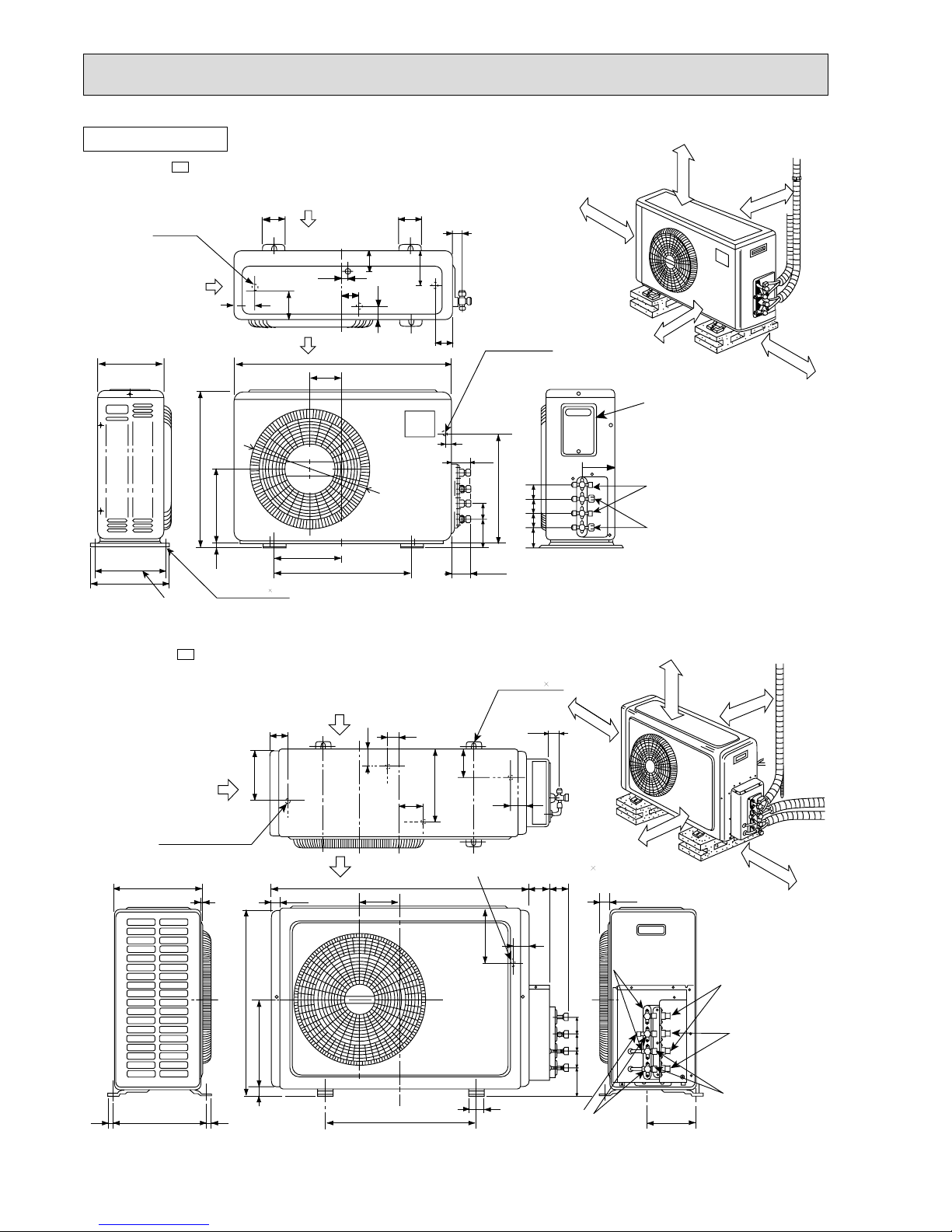
320
25
43
-
35-
155
90
104
74
260
10
780
500
122
40
540
320
285
255
Service panel
Gas refrigerant
pipe joint
Refrigerant pipe
(flared) [9.52 (MU-07/09RV
)
(MUH-07/09RV
)
[12.7 (MU-12RV
)
(MUH-12RV
)
Liquid refrigerant
pipe joint
Refrigerant pipe
(flared) [6.35
Air out
Air in
Air in
109
32
110
147
Drainage
3holes [33
If clearance
behind the outdoor
units only 40
B or 50B
side A must be
fully open.
10cm or more
10cm or more
10cm or more
Outdoor
unit
35cm or more
REQUIRED SPACE
A
40cm
or m
ore
Unit: mm
OUTDOOR UNIT
MU-07RV MU-09RV MU-12RV -
E1
E1
E1
MUH-07RV MUH-09RV MUH-12RV -
E1
E1
E1
Page 24
24
230
260
295
Bolt pitch
4 holes 10 21
Bolt pitch for installation
500
250
10
262.5
540
760
112
Wiring hole
Rear side
20
63
384.5
67 57
57
57
57
68
68
Stop valve 1/4F
Stop valve 3/8F
151
Service panel
58
60
21
35
50
70
50
50
56
105
Air in
Air in
Air out
Drainage
4 hole
[16.2
108
ø415
35cm or more
50cm ormore
10cm ormore
10cm or more
Unless any obstacle
exists in front ,right
Unless any obstacle
exists in front
and left sides.
10cm ormore
Unless any obstacle
exists in right , left and
rear sides.
REQUIRED SPACE
Unit A
MUX10RV-
E1
OUTDOOR UNIT
16 310 16
290
530
605
292
20
500
Bolt pitch for installation
50
90 57 57 57
Service port
Stop valve
3/8F
A
154.6
Service portBC
Gas side
union
3/8F
Liquid side
union
1/4F
Stop valve 1/4F
30
52
186
70 66
Electrical wiring entrance (Rear) 15 25
Unless any
obstacle exists
in right ,left ,
and rear sides.
C
B
Unless any
obstacle exists
in front, right
and left sides.
REQUIRED SPACE
4 holes-10 21
34
35
5480
236
91
51
168
57
850
133
Air out
Air in
4 Drain holes [
16.2
Air in
10cm ormore
50cm ormore
35cm ormore
10cm or more
10cm or more
A
MUX-18RV-
E1
Unit: mm
Page 25
25
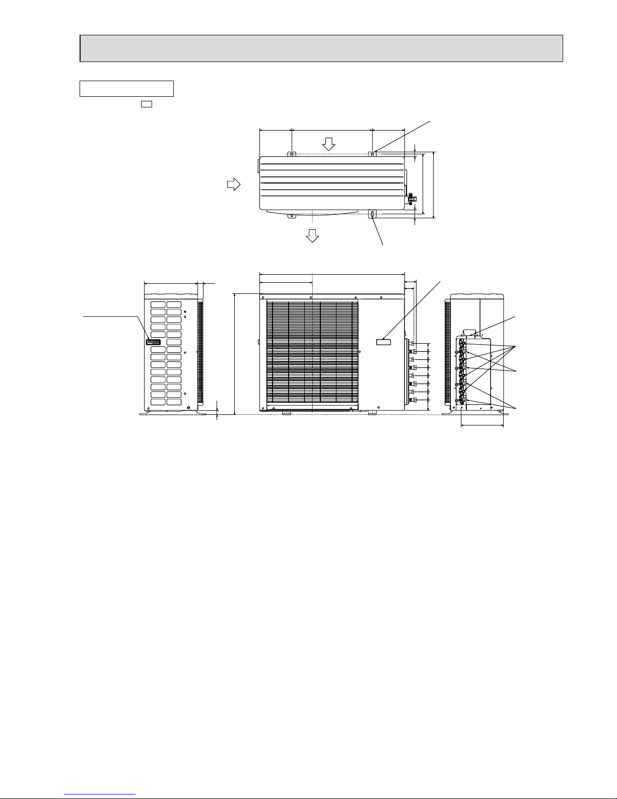
MUX-24RV-
E1
OUTDOOR UNIT
72.2
58.2
264.2
5050505050
50
50
64.8
2-U-Shape noched hols
(Base bolt M10)
Wiring hole
2-Oval hols(12Å~36)
(Base bolt M10)
Handle for moving
Gus pipe
(flared ɔ12.7)
Liquid pipe
(flared ɔ6.35)
Gus pipe
(flared ɔ9.52)
Air in
Air out
Air in
Handle for moving
372
412
200 200500
53
29
750
328
900
27
34330
Unit: mm
Page 26
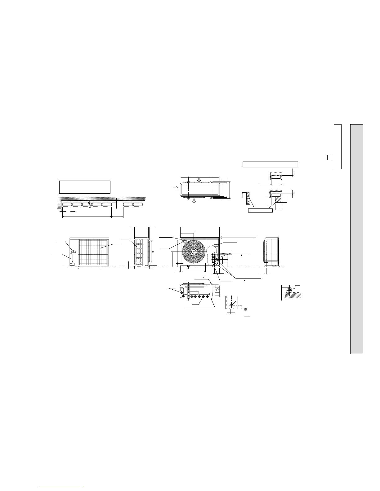
26
Necessary surrounding clearance
Necessary surrounding clearance for concentrated installation.
Leave overhead clearance fully
100
Handle for
monving
200
1000
2957
23
Max. 25
Base bolt length
To drain water in a mass, use
optional drain pan and drain
socket.
Drain pan : PAC-928DP,PAC-SA44DP
Drain socket : PAC-SA46DS
Drain hole
Drain hole
(Base bolt M10)
(Base bolt M10)
2 Oval hols (12 13)
2-U-Shape noched hols
33
524
339
302
524
77
2
25
12
17
R
6
40
116
A
B
57
107
57
57
505
30 870
650
10
Max. 10 units
Air in
Air in
Air out
185 185500
362
10
10
500
500
100
500
10
200
330
39.5 27.5
1715
Leave front clearance fully
Space for servicing
Leave overhead
clearance fully
Rear piping
hole
Rear
air-intake
Side
air-intake
Handle for
moving
Handle for moving
Liquid pipe
(flared 6.35)
Ground
terminal
Outlet guide
mounting hole
Gas pipe
(flared 9.52)
MXZ-18RV -
E1
Unit: mm
OUTDOOR UNIT
Page 27
27
MXZ-32RV -
E1
1.Installation space
2.Service space
More than
100
More than
200
More than
100
More than
500
More than
500
More than
10
More than
10
More than
500
Base bollt length
Less than
25
More than
350
More than
350
Service space
Air in
2-U-shape notched holes
(Base bolt M10)
(Base bolt M10)
Air in
Air out
200 200
387
355
27 40
(16) (16)
500
Veranda
Base
Rubber cushion
More than
500
Note : Leave front and both sides
clearance fully.
Note : Leave front and overhead
clearance fully.
Note : Leave front, overhead and
both clearance fully.
2-12 ✕ 36 Oval hole
23
10 35320
900
88
460
50
900
350.0
480.8
531.3
317
23
33
Handle for
moving
Air in
Indoor and outdoor
connect wiring
Air in
23✕45 hole
D unit connection
C unit connection
B unit connection
A unit connection
6.35 (flared) 1/4
Liquid pipe
12.7 (flared) 1/2 (A , B unit)
9.52 (flared) 3/8 (C , D unit)
[
[
[
Unit: mm
OUTDOOR UNIT
Page 28
28
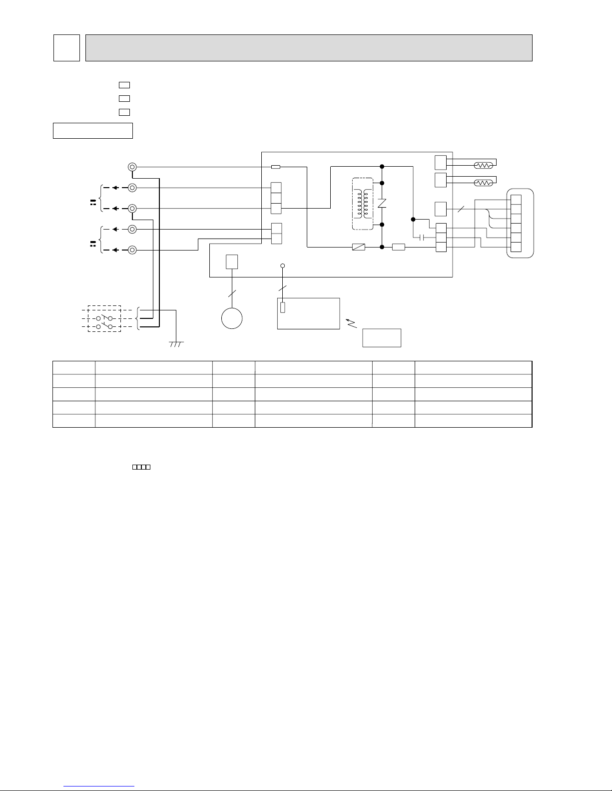
WIRING DIAGRAM
8
MSC-07RV MSC-09RV MSC-12RV -
E1
E1
E1
MODELS WIRING DIAGRAM
SYMBOL
SR141
TB
SYMBOL
MV
NR11
RT11
RT12
SYMBOL
C11
F11
HIC1
MF
NAME
NAME NAME
INDOOR FAN CAPACITOR
FUSE(3.15A)
DC/DC CONVERTER
INDOOR FAN MOTOR
VANE MOTOR
VARISTOR
ROOM TEMPERATURE THERMIST OR
INDOOR COIL THERMISTOR
SOLID STATE RELAY
TERMINAL BLOCK
CIRCUIT BREAKER
SR141
C11
RED
WHT
3
6
5
BRN
YLW
GRY
BLK
4
3
2
1
MF
121
CN
1
2
3
111
CN
112
CN
RT12
RT11
NR11
HIC1
TRANS
F11
ELECTRONIC CONTROL P.C. BOARD
CN211
TAB12
CN201
3
2
1
CN202
2
1
LD101T
151
CN
5
5
BRN
RED
BLU
WHT
BLK
BLU
BRN
TB
L
3
N
2
1
12V
TO OUTDOOR
UNIT
CONNECTING
POWER
SUPPLY
CORD
~/N 220-240V
50Hz
GRN/YLW
POWER MONITOR,
RECEIVER
P.C.BOARD
REMOTE
CONTROLLER
MV
FOR
MUH OR
MXZ TYPE
FOR
MU OR
MUX TYPE
12V
PE
INDOOR UNIT
NOTE:1. About the outdoor side electric wiring refer to the outdoor unit electric wiring diagram for servicing.
2. Use copper conductors only. (For field wiring)
3. Symbols below indicate.
/: Terminal block, : Connector
Page 29
29
MODELS WIRING DIAGRAM
OUTDOOR UNIT
SYMBOL
TB1,TB2
X62
21S4
52C
SYMBOL
MC
MF
NR61
RT61
SR61
SYMBOL
C1
C65
DSAR
F61
IC881
NAME
NAME NAME
COMPRESSOR CAPACITOR
OUTDOOR FAN CAPACITOR
SURGE ABSORBER
FUSE(2A)
DC/DC CONVERTER
COMPRESSOR(INNER THERMOSTAT)
OUTDOOR FAN MOTOR(INNER THERMOSTAT)
VARISTOR
DEFROST THERMISTOR
SOLID STATE RELAY
TERMINAL BLOCK
REVERSING VALVE COIL RELAY
REVERSING VALVE COIL
CONTACTOR
CIRCUIT BREAKER
POWER SUPPLY
~/N
220-240V
50Hz
12V
3
4
WHT
BLK
RED
MF
N
4
3
2
1
RT61
CN730
F61
SR61
GRN/YLW
3
R
S
C
WHT
RED
BLK
BLU
C1
52C
MC
21S4
3
2
1
BLK
BLK
CN721
X62
C65
TAB20
CN661
BLU
CN711
DEICER P.C. BOARD
BRN
BLK
RED
DSAR
BRN
TB2
N
FROM
INDOOR UNIT
CONNECTING
TB1
PE
L
IC881
TRANS
X62
NR61
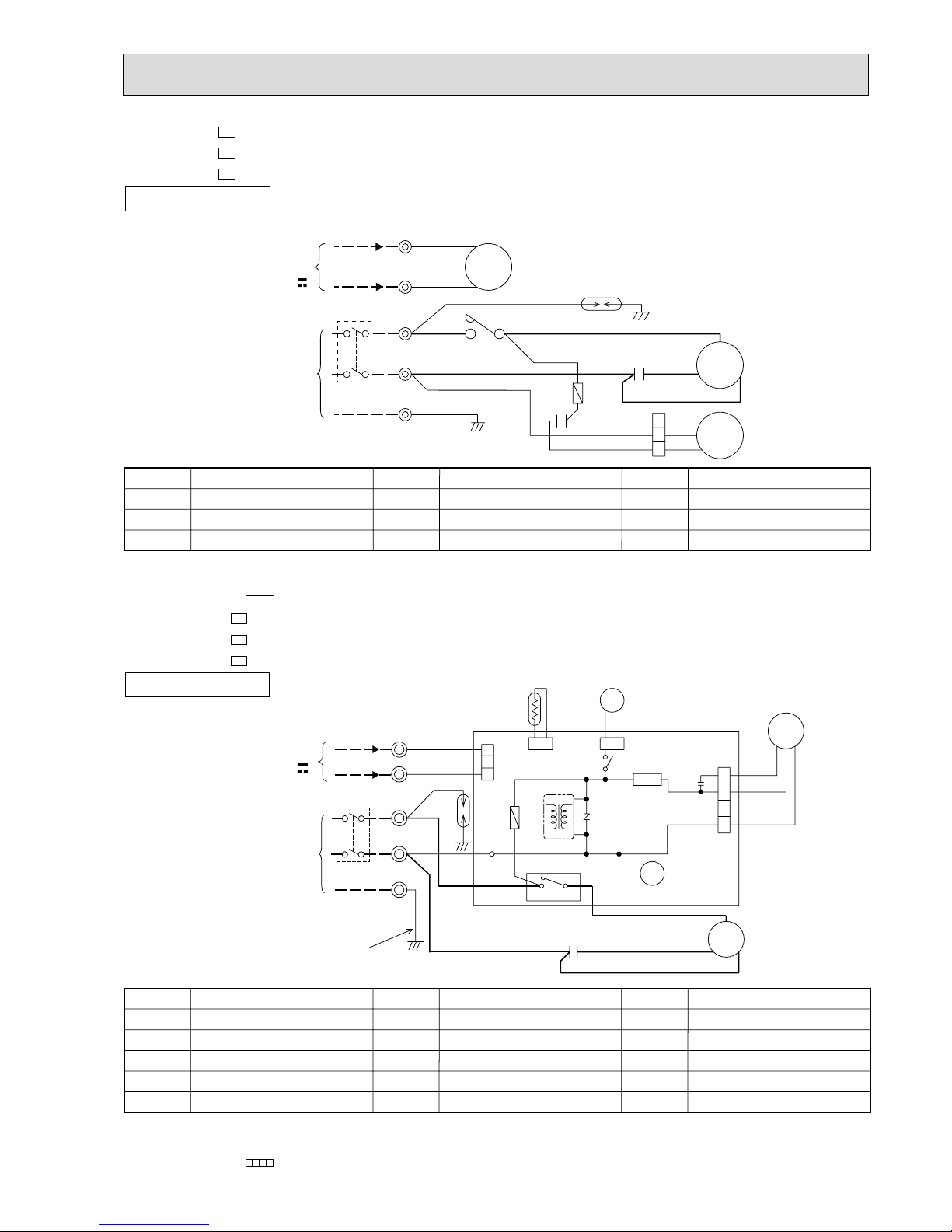
MUH-07RV MUH-09RV MUH-12RV -
E1
E1
E1
MODELS WIRING DIAGRAM
OUTDOOR UNIT
MU-07RV MU-09RV MU-12RV -
E1
E1
E1
NOTE:1. About the indoor side electric wiring refer to the indoor unit electric wiring diagram for servicing.
2.Use copper conductors only. (For field wiring)
3. Symbols below indicate.
/: Terminal block, : Connector
NOTE:1. About the indoor side electric wiring refer to the indoor unit electric wiring diagram for servicing.
2.Use copper conductors only. (For field wiring)
3. Symbols below indicate.
/: Terminal block, : Connector
CIRCUIT BREAKER
POWER SUPPLY
~/N
220-240V
50Hz
12V
GRN/YLW
TB2
RED
WHT
BLK
WHT
BLU
3
2
1
RED
MF
C2
MC
C1
S
R
C
N
2
FROM
INDOOR UNIT
CONNECTING
WHT
BLU
BLK
RED
WHT
52C
TB1
WHT
BLK
WHT
52C
PE
L
1
NO
COM
DSAR
BRN
F
BRN
SYMBOL
TB1,TB2
52C
SYMBOL
F
MC
MF
SYMBOL
C1
C2
DSAR
NAME
NAME NAME
COMPRESSOR CAPACITOR
OUTDOOR FAN CAPACITOR
SURGE ABSORBER
FUSE(2A)
COMPRESSOR(INNER THERMOSTAT)
OUTDOOR FAN MOTOR(INNER THERMOSTAT)
TERMINAL BLOCK
CONTACTOR
Page 30
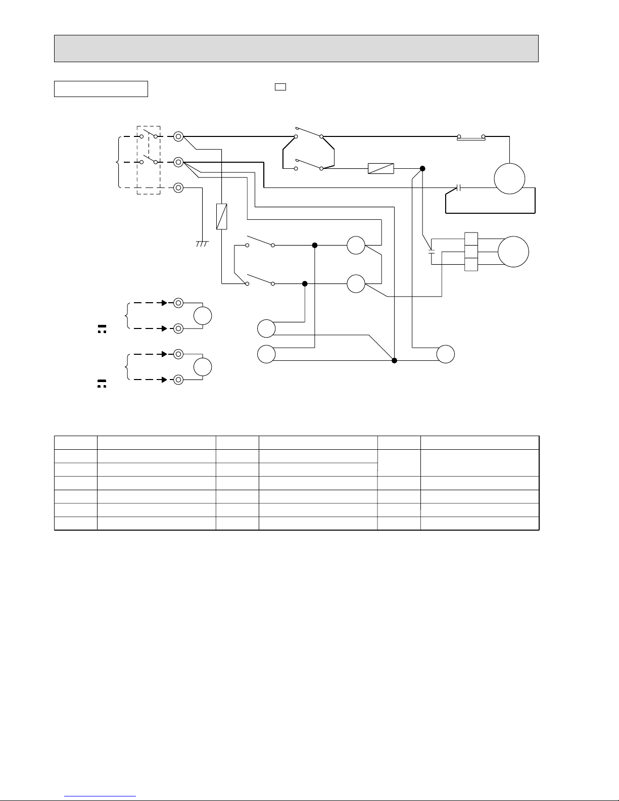
30
OUTDOOR UNIT
NOTE:1. About the indoor side electric wiring refer to the indoor unit electric wiring diagram for servicing.
2.Use copper conductors only. (For field wiring)
MODEL MUX-10RV-
E1
PE
WHT WHT
BRN
F13
F12
CIRCUIT BREAKER
WHT
1
TB2
2
TB2
TB3
1
BLU
BLU
BLK
RED
C2
2
2
1
1
43
X1
4X23
BLU
BLU
BLU
BLU
RED
YLW
RED
YLW
BLU
BRN
BLU
BLU
BLU
BRN
WHT
BRN
WHT WHT
BRN
NO COM
52C1
NO
52C2
COM
3
1
RED
BLU
RED
BLK
21R2
21R1
21R
52C1
TB
52C2
MF
WHT
2
WHT
1
51C
RS
MC
C
X2
N
L
POWER SUPPLY
~ / N
220-240V
50Hz
TB
GRN/YLW
BLK
2
2
1
1
WHT
ORN
GRY
FROM INDOOR
UNIT No.A
CONNECTING
12V
X1
1
2
1
2
FROM INDOOR
UNIT No.B
CONNECTING
12V
2
TB3
C1
SYMBOL
51C
52C1
51C2
SYMBOL
TB1,TB2,TB3
X1
X2
21R
21R1
21R2
SYMBOL
C1
C2
F12
F13
MC
MF
NAME
NAME NAME
COMPRESSOR CAPACITOR
OUTDOOR FAN CAPACITOR
FUSE(2A)
FUSE(2A)
COMPRESSOR
OUTDOOR FAN MOTOR
TERMINAL BLOCK
RELAY(A)
RELAY(B)
BYPASS VALVE SOLENOID COIL
SOLENOID COIL(A)
SOLENOID COIL(B)
OVERCURRENT RELAY
(INNER THERMOSTAT)
COMPRESSOR CONTACTOR(A)
COMPRESSOR CONTACTOR(B)
Page 31

31
FROM INDOOR
UNIT No.B
CONNECTING
12V
PE
BRN
WHT
F14
BLU
GRY
F13
CIRCUIT BREAKER
YLW
RED
BRN
BLU
BLU
BLU
WHT
F12
BLU
BLU
BLU
GRY
1
TB3
TB2
1
43
43
2
2
1
1
BLU
BLU
BLU
YLW
GRN/YLW
BLK
WHT
ORN
GRY
RED
YLW
2
1
51C2
BRN
YLW
BRN
BLU
WHT
WHT
WHT
RED
REDBLU
WHT
BRN
FROM INDOOR
UNIT No.A
CONNECTING
12V
2
TB3
TB2
X2
X1
1
2
1
2
C2
C1
RC
S
C
R
S
MC2
BLK
52CA
FROM INDOOR
UNIT No.C
CONNECTING
12V
BLU
52C2
21R2
RED 21
X2
X1
COMNO
52CA
3
X12
5
1
MF
MC1
51C1
1
1
BLK
ORN
WHT
YLW
RED
BLK
52C1
X11
X11
21R
X11
X12
21R1
X12
C3
TB
52C1
52C2
POWER SUPPLY
~ / N
220-240V
50Hz
1
2
5
4
2
3
1
L
N
4
78
4
6
2
6
2
2
87
3
1
5
3
21
4
43
BRN
BLU
BRN
BRN
WHT
RED
GRY
WHT
BLU
BLU
YLW
BLK
WHT
ORN
RED
OUTDOOR UNIT
MODEL MUX-18RV-
E1
NOTE:1. About the indoor side electric wiring refer to the indoor unit electric wiring diagram for servicing.
2.Use copper conductors only. (For field wiring)
SYMBOL
51C1
51C2
52CA
52C1
52C2
SYMBOL
TB
TB2,TB3
X1
X11
X12
X2
21R
21R1
21R2
SYMBOL
C1
C2
C3
F12
F13
F14
MC1
MC2
MF
NAME
NAME NAME
COMPRESSOR CAPACITOR(A)
COMPRESSOR CAPACITOR(B,C)
OUTDOOR FAN CAPACITOR
FUSE(2A)
FUSE(2A)
FUSE(2A)
COMPRESSOR(A)
COMPRESSOR(B,C)
OUTDOOR FAN MOTOR(INNER THERMOSTAT)
TERMINAL BLOCK
TERMINAL BLOCK
RELAY(B)
FAN MOTOR RELAY(A)
FAN MOTOR RELAY(B,C)
RELAY(C)
SOLENOID COIL
SOLENOID COIL(B)
SOLENOID COIL(C)
OVER CURRENT RELAY(A)
(INNER THERMOSTAT)
OVER CURRENT RELAY(B,C)
(INNER THERMOSTAT)
COMPRESSOR CONTACTOR(A)
COMPRESSOR CONTACTOR(B)
COMPRESSOR CONTACTOR(C)
Page 32

32
MODEL MUX-24RV-
E1
PE
1
BLU
WHT
WHT
BRN
BRN
BRN
BRN
BLU
BLU
BLU
WHT
WHT
WHT
2
1
TB9
TB8
12
1
BRN
TB10
2
BRN
BRN
BLU
BLK
RED
WHT
WHT
BLK
RED
C
MC1
R
S
C1
6
WHT
2
1
2
1
2
1
BLU
8
7
8
7
BLU
BLU
BLU
BLU
21RB
321
BLU
BLU
21
BLU
1
2
BLU
ORN
BLU
52C4
21R4
3
2
BLU
BLU
BLU
1
3
BLU
21R3
BLU
BLU
BLU
2
1
ORN
52C2
BLU
21R2
BLU
BLU
2
1
BLU
2
1
BLU
BLU
WHT
BLU
1
2
2
1
2
TB6
TB5
TB7
BLU
ORN
BLU
BLU
BRN
BRN
BRN
BRN
BRN
BLU
BLU
C11
WHT
ORN
ORN
BLU
BLU
BLU
BLU
BRN
TB4
TB3
TB2
TB1
BREAKER
2
1
X1
FROM INDOOR
UNIT No.A
CONNECTING
12V
2
1
YLW
YLW
X12
X11
21RA
52C3
52C1
21R1
34
X4
34
X3
34
X2
34
X1
3
4
43
52C4
52C3
GRY
ORN
WHT
YLW
34
43
5
1
3
N
L
1
3
2
4
5
2
1
POWER SUPPLY
~/N
220-240V
50Hz
52C1
52C2
TB
X11
BLK
RED
WHT
ORN
MF
1
5
X12
3
FROM INDOOR
UNIT No.D
CONNECTING
12V
X2
MC2
C
R
S
C2
2
1
2
1
X3
X4
FROM INDOOR
UNIT No.C
CONNECTING
12V
FROM INDOOR
UNIT No.B
CONNECTING
12V
2
1
ORN
ORN
WHT
WHT
GRY
GRY
GRN/YLW
2
2
1
1
F
CIRCUIT
OUTDOOR UNIT
NOTE:1. About the indoor side electric wiring refer to the indoor unit electric wiring diagram for servicing.
2.Use copper conductors only. (For field wiring)
SYMBOL
52C3
52C4
21R1
21R2
21R3
21R4
21RA
21RB
SYMBOL
TB
TB1~TB10
X1
X2
X3
X4
X11
X12
52C1
52C2
SYMBOL
C1
C2
C11
F
MC1
MC2
MF
NAME
NAME NAME
COMPRESSOR CAPACITOR(A,B)
OUTDOOR FAN CAPACITOR(C,D)
OUTDOOR FAN CAPACITOR
FUSE(3.15A)
COMPRESSOR(A,B)
(INNER THERMOSTAT)
COMPRESSOR(C,D)
(INNER THERMOSTAT)
OUTDOOR FAN MOTOR
(INNER THERMOSTAT)
TERMINAL BLOCK
TERMINAL BLOCK
RELAY(A)
RELAY(B)
RELAY(C)
RELAY(D)
FAN MORTOR RELAY(A,B)
FAN MORTOR RELAY(B,C)
COMPRESSOR RELAY(A)
COMPRESSOR RELAY(B)
COMPRESSOR RELAY(C)
COMPRESSOR RELAY(D)
SOLENOID COIL(A)
SOLENOID COIL(B)
SOLENOID COIL(C)
SOLENOID COIL(D)
SOLENOID COIL
SOLENOID COIL
Page 33

33
CIRCUIT BREAKER
T801
RT64 RT65
TB
FROM
INDOOR
UNIT
CONNECTING
12V
DS61
NF61
INDOOR
UNIT (A)
POWER SUPPLY
220-240V
~ / N
50Hz
INDOOR
UNIT (B)
TB
NF62
C61
C64
C63
L61
L
DS63
C67
SSR61
C65
X67
X60
MF
MC
TR
R65
21S4
R64
X64
CT61
NR61
AR61
ELECTRONIC CONTROL
P.C.BOARD
LEV A
LEV B
RELAY P.C.BOARD
RT66RT67 RT61
HPS
RT62 RT63
PE
6
5
6
1234
54321
543216
321
12
12
12
12
2
3
4
1
2
3
4
1
N
3
N
3
L
N
2
4321
8
V
WU
7
6
5
4
3
2
1
W
V
UP
N
2345
1
1
1
2
3
4
1234 1234
3
2
1
LDE1
LD62
FUSE2
F62
FUSE1
TAB91
CN683
3
4
1
~+-
~
+
~
~
~
-
+-
2
CN61
CN63
CN701
EwN
BwN
EvN
BvN
EuN
BuN
EwP
BwP
EvP
BvP
EuP
BuP
CN671CN641CN681CN661
CN682
CN731
CN621
CN801
LD77
LD74
LD73
LD71
LD72
3
4
2
1
+
-
TB62
TB61
LD61
3
4
LD63
LD64
CN941
CN771
CN761
CN601 CN611
TBAC1
TBAC2
RED
RED
BRN
BLK
WHT
ORN
GRY
GRY
GRY
GRY
GRN/YLW
BLU
RED
BLU
BLU
RED
BLU
BLU
BLU
ORN
YLW
WHT
RED
BLK
BLK
BLK
BLK
GRY
GRY
GRY
GRY
BLU
RED
BLK
WHT
WHT
BLK
RED
GRY
GRY
RED
RED
GRN
YLW
RED
BLU
BLK
WHT
BLU
RED
BLK
BLU
RED
ORN
RED
BLK
BLU
WHT WHT
BLU
GRN
YLW
ORN
RED
BRN
RED
WHT
BLK
RED
WHT
BLK
YLW
RED
BRN
RED
ORN
YLW
GRN
BLU
BLU
ORN
YLW
WHT
RED
GRN
BLK
BLU
BRN
BLK
YLW
BRN
RED
YLW
YLW
BLU
RED
BRN
RED
MODELS MXZ-18RV-
E1
NOTE:1. About the indoor side electric wiring refer to the indoor unit electric wiring diagram for servicing.
2.Use copper conductors only. (For field wiring)
SYMBOL
RT63
RT64
RT65
RT66
RT67
R64
SYMBOL
L
LEV A,B
L61
MC
MF
NF61,62
NR61
RT61
RT62
SYMBOL
AR61
CT61
C61
C63
C64
C65
C67
DS61,63
FUSE1
FUSE2
F62
HPS
NAME
NAME NAME
SURGE ABSORBER
CURRENT TRANSFORMER
POWER-FACTOR CAPACITOR
CERAMIC CAPACITOR
CERAMIC CAPACITOR
INDOOR FAN CAPACITOR
SMOOTHING CAPACITOR
DIODE MODULE
FUSE(1A)
FUSE(3.15A)
FUSE(3.15A)
HIGH PRESSURE SWITCH
REACTOR
EXPANSION VALVE
CMC COIL
COMPRESSOR
INDOOR FAN MOTOR
(INNER THERMOSTAT)
NOISE FILTER
VARISTOR
DEFROST TEMPERATURE
THERMISTOR
DISCHARGE TEMPERATURE
THERMISTOR
FIN TEMPERATURE
THERMISTOR
GAS PIPE TEMPERATURE B.
THERMISTOR
GAS PIPE TEMPERATURE A.
THERMISTOR
SUCTION TEMPERATURE
THERMISTOR
EVAPORATION TEMPERATURE
THERMISTOR
CURRENT-LIMITING
RESISTOR
SYMBOL
R65
SSR61
TB
TR
T801
X60,67
X64
21S4
NAME
CURRENT-DETECTING
RESISTOR
SOLID STATE RELAY
TERMINAL BLOCK
POWER TRANSISTOR
MODULE
TRANSFORMER
FAN MOTOR RELAY
RELAY
REVERSING VALVE
SOLENOID COIL
OUTDOOR UNIT
Page 34

34
POWER SUPPLY
~/N 220-240V
50Hz
INDOOR
UNIT (A)
CIRCUIT BRAKER
TB2
TB3
BLU
RED
TB4
X64
GRN/YLW
GRN/YLW
CN720
CN601
0
4
X64
LD62
CN913
CN791
CN901
64
2
CN902
CN851 CN852
MF61
CH
21S4 21S2
12 12
21
21
12
12
34
123456
12 34567
123456
CN912
C65
LD63
LD64
LDB
LDB
LD61
LDE
L61
F911
SSR61
SSR62
SSR63
X63
X62
X61
1
6
L
N
3
N
INDOOR
UNIT (B)
BLU
ORN
CN602
12
3
3
3
N
INDOOR
UNIT (C)
BLU
YLW
CN603
12
N
INDOOR
UNIT (D)
BLU
BRN
CN604
12
N
BLK
BRN
GRY
BLK
BLK
WHT
YLW
RED
RED
RED
BRN
BLU
ORN
YLW
WHT
ORN
WHT
BLK
BLU
YLW
RED
BLU
BLU
WHT
WHT
ORN
ORN
RED
RED
YLW
YLW
YLW
BLK
BLK
ORN
ORN
BRN
GRY
X65
X66
X67
X67
63H2
X65
X66
CN552
CN553
BLK
RELAY
P.C. BOARD
WHT
WHT
RED
WHT
V
UW
YLW
A
K
L
WHT
NOISE FILTER
P.C.BOARD
RED
DS61
DS62
C61
CT
61
C63 C62
+
+
-
+-+
-
-
BLKREDR
BLU
LEV A
CN792
123456
RED
BRN
BLU
ORN
YLW
WHT
LEV B
CN793
123456
RED
BRN
BLU
ORN
YLW
WHT
LEV C
CN794 CN722 CN663
63H1 RT63
123456
CN662
1234567812 12
123
34
RED
RED
RED
63L
BLK
BLK
BLK
BLK
RT66 RT68
RT67 RT69
GRY
GRY
GRY
GRY
GRY
GRY
GRY
GRY
CN661
CN705
7654321
CN515
1234
4321
CN801
CN501
TAB62
TAB63
T801
CT62
TAB66
TAB65
TAB64
I.P.M P.C. BOARD
F801
(1A)
CN704
CN514
CN554CN551
CN723
12345678
RT62 RT64
RT61 RT65
GRY
GRY
BLK
BLK
GRY
GRY
GRY
GRY
BRN
BLU
ORN
YLW
WHT
LEV D
ELECTRONIC CONTROL P.C. BOARD
MC
PE
FROM INDOOR UNIT
CONNECTING 12V
SYMBOL
C61
C62,63
C65
CH
CT61,62
DS61
DS62
F801
F911
L
L61
LEV A~D
SYMBOL
MC
MF61
R
RT61
RT62
RT63
RT64
RT65
RT66,67
RT68,69
SSR61,62
SSR63
NAME
POWER FACTOR CAPACITOR
SMOOTHING CAPACITOR
OUTDOOR FAN CAPACITOR
CRANKCASE HEATER
CURRENT TRANSFORMER
DIODE MODULE
DIODE STACK
FUSE (1A)
FUSE (1A)
REACTOR
COMMON MODE CHOKE COIL
EXPANSION VALVE
NAME
COMPRESSOR
OUTDOOR FAN MOTOR (INNER FUSE)
RESISTOR
DISCHARGE TEMPERATURE THERMISTOR
DEFROST TEMPERATURE THERMIST OR
FIN TEMPERATURE THERMISTOR
EVAPORATION TEMPERATURE THERMISTOR
SUCTION TEMPERATURE THERMISTOR
GUS PIPE TEMPERATURE THERMISTOR
GUS PIPE TEMPERATURE THERMISTOR
SOLENOID COIL RELAY
CRANKCASE HEATER RELAY
SYMBOL
T801
TB2,3,4
X61,62,63
X64,65
X66,67
21S2
21S4
63H1
63H2
63L
NAME
TRANSFORMER
TERMINAL BLOCK
FAN MOTOR RELAY
RELAY
RELAY
SOLENOID COIL
R.V. COIL
HIGH PRESSURE SWITCH
HIGH PRESSURE SWITCH
LOW PRESSURE SWITCH
NOTE:1. About the indoor side electric wiring refer to the indoor unit electric wiring diagram for servicing.
2.Use copper conductors only. (For field wiring)
MODELS MXZ-32RV-
E1
OUTDOOR UNIT
Page 35

35
REFRIGERANT SYSTEM DIAGRAM
9
MSC-07RV MSC-09RV -
E1
E1
MU-07RV MU-09RV -
E1
E1
MSC-12RV -
E1
MU-12RV -
E1
INDOOR UNIT
INDOOR UNIT
OUTDOOR UNIT
OUTDOOR UNIT
Indoor
heat
exchanger
Room temperature
thermistor
RT11
Refrigerant pipe [9.52
(Option)
(with heat insulator)
Outdoor
heat
exchanger
Capillary tube
[3.0x[1.4x600
Strainer
Refrigerant pipe [6.35
(Option)
(with heat insulator)
Refrigerant flow in cooling
Unit:mm
Unit:mm
Refrigerant pipe [12.7
(Option)
(with heat insulator)
Stop valve
(with service port)
Stop valve
(with service port)
Strainer
Refrigerant pipe [6.35
(Option)
(with heat insulator)
Stop valve
Capillary tube
[3.0x[1.6x600
Refrigerant flow in cooling
Outdoor
heat
exchanger
Room temperature
thermistor
RT11
Indoor coil
thermistor
RT12
Indoor coil
thermistor
RT12
Compressor
Indoor
heat
exchanger
Compressor
Flared connection
Flared connection
Flared connection
Flared connection
Page 36

36
Unit:mm
MSC-12RV -
E1
MUH-12RV -
E1
INDOOR UNIT
OUTDOOR UNIT
(with heat insulator)
(with heat insulator)
Refrigerant pipe [12.7
(Option)
Reversing valve
Muffler
Stop valve
(with service port)
Strainer
Refrigerant pipe [6.35
(Option)
Stop valve
Capillary tube
[3.0x[1.6x700
Check
valve
Refrigerant flow in cooling
Refrigerant flow in heating
Defrost
thermistor
RT61
Outdoor
heat
exchanger
Room temperature
thermistor
RT11
Indoor coil
thermistor
RT12
Capillary tube
[3.0x[1.8x300
Flared connection
Flared connection
Compressor
Indoor
heat
exchanger
Accumulator
Reversing valve coil
heating ON
cooling OFF
MSC-07RV MSC-09RV -
E1
E1
MUH-07RV MUH-09RV -
E1
E1
INDOOR UNIT
OUTDOOR UNIT
Indoor
heat
exchanger
Room temperature
thermistor
RT11
(with heat insulator)
Refrigerant pipe [ 9.52
(Option)
Muffler
Reversing valve
Defrost
thermistor
RT61
Accumulator
Strainer
Outdoor
heat
exchanger
Capillary tube
[3.0x[1.4x800
(2 pcs)
Capillary tube
[3.0x[1.6x600(MUH-07RV)
[3.0x[1.6x400(MUH-09RV)
Capillary tube
[3.0x[1.4x600(MUH-07RV)
[3.0x[1.4x550(MUH-09RV)
Check valve
Strainer
Refrigerant pipe [6.35
(Option)
(with heat insulator)
Refrigerant flow in cooling
Refrigerant flow in heating
Unit:mm
Stop valve
(with service
port)
Indoor coil
thermistor
RT12
Reversing valve coil
heating ON
cooling OFF
Capillary tube
[3.0x[1.4x500(2pcs)
Flared connection
Flared connection
Compressor
Stop valve
Strainer
Page 37

37
Piping size O.D : mm Length of connecting pipe : m
Models
Piping size O.D : mm Length of connecting pipe : m
Models
Refrigerant piping
Max. length : m
A
10
15
Indoor unit
Gas 0.43
Liquid 0.5
Gas
9.52
12.7
Liquid
6.35
Outdoor unit
Gas 0
Liquid 0
MSC-07RV - E1
MUH-07RV - E1
MSC-09RV - E1
MUH-09RV - E1
MSC-12RV - E1
MUH-12RV - E1
{
{
{
Refrigerant piping
Max. length : m
A
10
15
Indoor unit
Gas 0.43
Liquid 0.5
Gas
9.52
12.7
Liquid
6.35
Outdoor unit
Gas 0
Liquid 0
MSC-07RV - E1
MU-07RV - E1
MSC-09RV - E1
MU-09RV - E1
MSC-12RV - E1
MU-12RV - E1
{
{
{
Indoor
unit
w Max. Height
difference 5m
Height difference should be within
5m regardless of which unit,
indoor or outdoor position is high.
Outdoor unit
Refrigerant Piping
Max.length
A
Models
Refrigerant piping length (one way)
Models
Refrigerant piping length (one way)
Outdoor unit precharged
800
1190
15m
400
7m
0
10m
150
MSC-07RV - E1
MUH-07RV - E1
MSC-09RV - E1
MUH-09RV - E1
MSC-12RV - E1
MUH-12RV - E1
{
{
{
Calculation : Xg=50g/m 5 x(A-7)m
Outdoor unit precharged
800
850
880
15m
120
7m
0
10m
45
MSC-07RV - E1
MU-07RV - E1
MSC-09RV - E1
MU-09RV - E1
MSC-12RV - E1
MU-12RV - E1
{
{
{
Calculation : Xg=15g/m x(A-7)m
MAX. HEIGHT DIFFERENCE
ADDITIONAL REFRIGERANT CHARGE(R-22 : g)
MAX. REFRIGERANT PIPING LENGTH
Page 38

38
MSC-07RV
Indoor unit A
E1
MUX-10RV
Outdoor unit
Additional piping max. length 10m
Max. length
difference
5m
E1
MSC-07RV
Indoor unit B
E1
OUTDOOR UNITINDOOR UNIT
UNIT A
Indoor
heat
exchanger
Indoor coil
thermistor
RT12
Room
temperature
thermistor
RT11
UNIT B
Indoor
heat
exchanger
Outdoor
heat
exchanger
Indoor coil
thermistor
RT12
Room
temperature
thermistor
RT11
(option)
(With insulation)
Refrigerant pipe
9.52 (3/8)
(option)
(With insulation)
Refrigerant pipe
9.52 (3/8)
Flared connection
(option)
(With insulation)
Refrigerant pipe
6.35 (1/4)
(option)
(With insulation)
Refrigerant pipe
6.35 (1/4)
Flared connection
Stop valve
with service port
Solenoid valve
21R1
Solenoid valve
21R
Solenoid valve
21R2
Capillary tube
1.4 x 400
Capillary tube
1.4 x 400
Capillary tube
Capillary tube
1.4 x 200
1.6 x 1,000
Compressor
Refrigerant flow
Stop valve
with service port
Stop
valve
Stop
valve
MSC-07RV-
E1
MAX. REFRIGERANT PIPING LENGTH & MAX. HEIGHT DIFFERENCE
ADDITIONAL REFRIGERANT CHARGE (R-22:g)
PIPING PREPARATION
1 Table below shows the specifications of pipes commercially available.
2 Ensure that the 2 refrigerant pipes are well insulated to prevent condensation.
3 Refrigerant bending radius must be 10cm or more.
MUX-10RV-
E1
Unit : mm
Outdoor unit refrigerant piping length (one way,2unit total)
MSX-10RV
- precharged (g) 7m 8m 9m 10m 11m 12m 13m 14m 15m
unit+ unit 1000g 0 10 20 30 40 50 60 70 80
E1
Outside diameter Insulation
UNIT No. Pipe
mm inch thickness
Insulation material
and
UNIT
For liquid 6.35 1/4 8 mm Heat resisting foam plastic
For gas 9.52 3/8 8 mm 0.045 specific gravity
BA
A
B
Page 39

39
OUTDOOR UNIT
INDOOR UNIT
UNIT A
Indoor
heat
exchanger
Indoor coil
thermistor
RT12
Room
temperature
thermistor
RT11
UNIT B
Indoor
heat
exchanger
Outdoor
heat
exchanger
Indoor coil
thermistor
RT12
Room
temperature
thermistor
RT11
(option)
(With insulation)
Refrigerant pipe
9.52<3/8>
(option)
(With insulation)
Refrigerant pipe
9.52<3/8>
(option)
(With insulation)
Refrigerant pipe
6.35<1/4>
Flared connection
(option)
(With insulation)
Refrigerant pipe
6.35<1/4>
Flared connection
Refrigerant pipe
9.52<3/8>
(option)
(With insulation)
Refrigerant pipe
6.35<1/4>
Flared connection
Stop valve
with service port
Stop valve
Solenoid valve
21R1
Solenoid valve
21R1
Solenoid valve
21R
Stop valve
with
service port
Stop valve
with
service port
Capillary tube
1.4 ✕ 1100
Capillary tube
1.6 ✕ 1100
Capillary tube
1.6 ✕ 1100
Capillary tube
1.6 ✕ 300
Capillary tube
1.6 ✕ 1,000
Compressor(A)
Compressor(B,C)
Refrigerant flow
MSC-09RV
E1
MSC-09RV
E1
UNIT C
Indoor
heat
exchanger
Indoor coil
thermistor
RT12
Room
temperature
thermistor
RT11
MSC-09RV
E1
MSC-09RV-
E1
MUX-18RV-
E1
Unit : mm
Page 40

40
LA
Indoor unit A
MSC-09RV - E1
HL
B HLC
H
Indoor unit B
MSC-09RV - E1
Indoor unit C
MSC-09RV - E1
Outdoor unit
MUX-18RV - E1
UNIT No.
Insulation
thickness
Pipe
For liquid
For gas
Outside diameter
mm inch
6.35 1/4
9.52 3/8
8mm
8mm
, and
unit
C
BA
Insulation material
Heat resisting foam plastic
0.045 specific gravity
Outdoor unit
precharged
750g
Refrigerant piping length (one way)
7m 8m 9m 10m
0 153045
unit + unit
CB
Outdoor unit
precharged
750g
Refrigerant piping length (one way,2 unit total)
7m
0
8m
15
9m
30
10m4511m6012m7513m9014m
105
15m
120
MSX-18RV-
E1
ADDITIONAL REFRIGERANT CHARGE (R-22:g)
Max.
limits
UNIT No.
A
B
C
Pipe length
10m
10m
Total
15m
L
B
+
L
C
10m
L
A
LB
LC
Height difference (H)
5m
5m
5m
No. of bends
10
10
Total
15
10
PIPING PREPARATION
1Table below shows the specifications of pipes commercially available.
2Ensure that the 2 refrigerant pipes are well insulated to prevent condensation.
3Refrigerant bending radius must be 10cm or more.
MAX.REFRIGERANT PIPING LENGTH & MAX. HEIGHT DIFFERENCE
unit
A
Note: The length of piping to individual units (A,B,C) should not exceed 10 meters.
If units B and C are linked, the maximum combined length of piping should not exceed 15 meters.
Page 41

41
MSC-09RVMSC-12RV-
E1
E1
MUX-24RV-
E1
Unit : mm
OUTDOOR UNITINDOOR UNIT
UNIT A
Indoor
heat
exchanger
Indoor coil
thermistor
RT12
Room
temperature
thermistor
RT11
UNIT B
Indoor
heat
exchanger
Outdoor
heat
exchanger
Indoor coil
thermistor
RT12
Room
temperature
thermistor
RT11
(option)
(With insulation)
Refrigerant pipe
{12.7 (1/2)
(option)
(With insulation)
Refrigerant pipe
{12.7 (1/2)
Flared connection
(option)
(With insulation)
Refrigerant pipe
{6.35 (1/4)
(option)
(With insulation)
Refrigerant pipe
{6.35 (1/4)
Flared connection
Stop valve
with service port
Solenoid valve
21R1
Solenoid valve
21RA
Solenoid valve
21R2
Capillary tube
{1.6 x 420
Capillary tube
{1.6 x 420
Capillary tube
Capillary tube
{1.8 x 260
{1.6 x 1,000
Compressor 1
Refrigerant flow
Stop valve
with service port
Stop
valve
Stop
valve
UNIT C
Indoor
heat
exchanger
Indoor coil
thermistor
RT12
Room
temperature
thermistor
RT11
UNIT D
Indoor
heat
exchanger
Indoor coil
thermistor
RT12
Room
temperature
thermistor
RT11
(option)
(With insulation)
Refrigerant pipe
{9.52 (3/8)
(option)
(With insulation)
Refrigerant pipe
{9.52 (3/8)
Flared connection
(option)
(With insulation)
Refrigerant pipe
{6.35 (1/4)
(option)
(With insulation)
Refrigerant pipe
{6.35 (1/4)
Flared connection
Stop valve
with service port
Solenoid valve
21R3
Solenoid valve
21RB
Solenoid valve
21R4
Capillary tube
{1.6 x 650
Capillary tube
{1.6 x 650
Capillary tube
Capillary tube
{1.6 x 400
{1.6 x 1,000
Compressor 2
Stop valve
with service port
Stop
valve
Stop
valve
MSC-12RV- E1
MSC-12RV- E1
MSC-09RV- E1
MSC-09RV- E1
Page 42

42
UNIT No.
Insulation
thickness
Pipe
For liquid
For gas
For liquid
For gas
Outside diameter
mm inch
6.35 1/4
12.7
6.35
9.52
1/2
1/4
3/8
8mm
8mm
8mm
8mm
Insulation material
Heat resisting foam plastic
0.045 specific gravity
MSX-24RV-
E1
ADDITIONAL REFRIGERANT CHARGE (R-22g)
Max.
limits
UNIT No.
A
B
C
D
Pipe length
20m
20m
Total
30m
Total
30m
LC
+
LD
LA
+
LB
20m
20m
LA
LB
LC
LD
Height difference (H)
10m
10m
10m
10m
No. of bends
10
10
Total
15
Total
15
10
10
PIPING PREPARATION
MAX.REFRIGERANT PIPING LENGTH & MAX. HEIGHT DIFFERENCE
Note: The length of individual units (A,B,C,D) should not exceed 20 meters.
If units Aand B or C and D are linked, the maximum combined length of piping should not exceed 30 meters.
Outdoor unit
precharged
(g)
1000g
1000g
Refrigerant piping length (one way, 2 unit total)
10m11m12m13m14m15m16m17m18m19m20m21m22m23m24m25m26m27m28m29m30
m
0 102030405060
70 80 90 100 110 120 130 140 150 160 170 180 190 200
0
unit + unit
BA
and unit
BA
and unit
DC
UNIT No.
unit + unit
DC
Outdoor unit
MUX-24RV- E1
Indoor unit A
MSC-12RV- E1
Indoor unit B
MSC-12RV- E1
Indoor unit C
MSC-09RV- E1
Indoor unit D
MSC-09RV- E1
HLDHLCHLBHLA
10 20 30 40 50 60
70 80 90 100 110 120 130 140 150 160 170 180 190 200
Page 43

43
9.52
6.35
9.52
9.52
2.0X 0.6X500
Charge port
Capillary
tube
4.0X
2.4X
400
Capillary
tube
4.0X
2.4X
300
Expansion
valve(LEV)
Expansion
valve(LEV)
Strainer
Strainer
Capillary
tube
4.0X
2.4X
300
Ball valve with
service port
Service
port
(high pressure)
Reversing
valve
Suction temperature
thermistor
RT66
Gas pipe
thermistor
Gas pipe
thermistor
Muffler
Compressor
High pressure
switch
Discharge
temperature
thermistor
RT62
Service
port
(Low pressure)
Refrigerant flow in cooling
Refrigerant flow in heating
Reversing valve coil
heating ON
cooling OFF
Strainer
Capillary
tube
Evaporation
temperature
thermistor
RT67
Defrost
thermistor
RT61
Outdoor
heat
exchanger
6.35
Accumlator
Ball valve with
service port
Indoor unit
B
Indoor unit
A
Indoor unit
A
Indoor unit
B
Unit:mm
MXZ-32RV -
E1
MXZ-18RV -
E1
Indoor unit
D
Ball valve with
service port
Ball valve with
service port
Distributor
Strainer StrainerLEV
Oil
separator
Compressor
High pressure
switch 1
Suction
temperature
thermistor
Low pressure switch
Accumulator
Capillary tube
Capillary tube
Capillary tube
Reversing valve
2-way-valve
Discharge
temperature
thermistor
Evaporation
temperature
thermistor
(RT67)
Defrost
thermistor
Strainer
Distributor
Outdoor
heat
exchanger
High pressure
switch 2
Unit D gas pipe temperature thermistor
[9.52
Indoor unit
C
Unit C gas pipe temperature thermistor
[9.52
[6
Indoor unit
B
Unit B gas pipe temperature
thermistor
[12
Indoor unit
A
Indoor unit
A
Strainer StrainerLEV
[6
Indoor unit
B
Strainer StrainerLEV
[6
Indoor unit
C
Strainer StrainerLEV
[6
Indoor unit
D
Unit A gas pipe
temperature thermistor
[12
[16
[16
[9.52
[16
[3.0✕[2.0✕ 500
Capillary tube
[2.5✕[0.6✕ 750
[2.5✕ [0.6✕1000
[3.0✕[2.0✕500
Capillary tube
[4.0✕[2.4✕ 400
Refrigerant flow in cooling
Refrigerant flow in heating
Reversing valve coil
heating ON
cooling OFF
Crankcase
heater
Page 44

44
MXZ-32RV -
E1
Piping length each indoor unit (a, b, c, d) 25m
Total piping length (a+b+c+d) 60m
Height difference between units (H) 10m
Bending point for each unit 25
Total bending point 60
❋It does not matter which unit is higher.
a
b
c
d
Outdoor
unit
Indoor
units
H
H
H
MAX REFRIGERANT PIPING LENGTH
MXZ-18RV -
E1
Piping length for each indoor unit (a,b) 20m
Total piping length (a+b) 30m
Height difference between units (H) 7m
Bending point for each unit 15
Total bending point 30
❈ It does not matter which unit is higher
a
b
Outodoor
unit
H
H
H
Page 45

45
●Refrigerant pipe diameter is different according to indoor unit to be connected. When using extention pipes,refer to the tables
below.
●When diameter of refrigerant pipe is different from that of outdoor unit union, use optional Different-diameter pipe. For further
information on Different-diameter pipe,see page BACK COVER.
Indoor unit
Extention pipe diameter
class Pipe diameter
Liquid 6.35(1/4) Liquid 6.35(1/4)
07/09
Gas 9.52(3/8) Gas 9.52(3/8)
Liquid 6.35(1/4) Liquid 6.35(1/4)
12(13)
Gas 12.7(1/2) Gas 12.7(1/2)
Liquid 6.35(1/4) Liquid 6.35(1/4)
18
Gas 15.88(5/8) Gas 15.88(5/8)
Outdoor unit union diameter
For
Liquid 6.35(1/4)
Indoor unit A
Gas 12.7(1/2)
Liquid 6.35(1/4)
Indoor unit B
Gas 12.7(1/2)
Liquid 6.35(1/4)
Indoor unit C
Gas 9.52(3/8)
Liquid 6.35(1/4)
Indoor unit D
Gas 9.52(3/8)
Unit : mm (inch)
PIPE SIZE SELECTION
MXZ-18RV -
E1
● Refrigerant pipe diameter is different according to indoor unit to be connected. When using extension pipes, refer to the
table below.
● When diameter of refrigerant pipe is different from that of outdoor unit union, use optional L-joint. For further information on
L-joint, see page BACK COVER.
Indoor unit
Extention pipe diameter
class Pipe diameter
Liquid 6.35(1/4) Liquid 6.35(1/4)
07/09
Gas 9.52(3/8) Gas 9.52(3/8)
Liquid 6.35(1/4) Liquid 6.35(1/4)
12
Gas 12.7(1/2) Gas 12.7(1/2)
Outdoor unit union diameter
For
Liquid 6.35(1/4)
Indoor unit A
Gas 9.52(3/8)
Liquid 6.35(1/4)
Indoor unit B
Gas 9.52(3/8)
Unit : mm (inch)
MXZ-32RV -
E1
Page 46

46
10
The standard data contained in these specifications apply only to the operation of the air conditioner under normal conditions,
since operating conditions vary according to the areas where these units are installed. The following information has been provided to clarify the operating characteristics of the air conditioner under the conditions indicated by the performance curve.
(1) GUARANTEED VOLTAGE
Rated voltage : ±10% (198 ~ 264V
),50Hz
(2) AIR FLOW
Air flow should be set at MAX.
(3) MAIN READINGS
(1) Indoor intake air wet-bulb temperature : °CWB
(2) Indoor outlet air wet-bulb temperature : °CWB
(3) Outdoor intake air dry-bulb temperature : °CDB
(4) Total input: W
(5) Indoor intake air dry-bulb temperature : °CDB
(6) Outdoor intake air wet-bulb temperature : °CWB
(7) Total input : W
Indoor air wet/dry-bulb temperature difference on the left side of the chart on page 14 and 15 shows the difference
between the indoor intake air wet/dry-bulb temperature and the indoor outlet air wet/dry-bulb temperature for your reference at service.
How to measure the indoor air wet-bulb/dry-bulb temperature difference
1. Attach at least 2 sets of wet-and dry-bulb thermometers to the indoor air intake as shown in the figure, and at least 2 sets
of wet-and dry-bulb thermometers to the indoor air outlet. The thermometers must be attached to the position where air
speed is high.
2. Attach at least 2 sets of wet-and dry-bulb thermometers to the outdoor air intake.
Cover the thermometers to prevent direct rays of the sun.
3. Check that the air filter is cleaned.
4. Open windows and doors of room.
5. Press the EMERGENCY OPERATION switch once(twice) to start the EMERGENCY COOL(HEAT
<MUH-07/09/12RV
>
)
MODE.
6. When system stabilizes after more than 15 minutes, measure temperature and take an average temperature.
7. 10 minutes later, measure temperature again and check that the temperature does not change.
INDOOR UNIT
OUTDOOR UNIT
}
}
Cooling
Heating
<MUH-07/09/12RV
>
PERFORMANCE CURVES
Wet-and dry-bulb
thermometers
Wet-and dry-bulb
thermometers
MSC-07RV - E1
(MU-07RV - E1 )
(MU-12RV - E1 )
MSC-12RV - E1
(MU-09RV - E1 )
MSC-09RV - E1
8.9
8.2
7.4
6.7
6.0
5.4
11.6
10.6
9.6
8.7
7.8
6.9
10.2
9.3
8.5
7.7
6.9
6.1
MUH-07RV MUH-09RV MUH-12RV -
E1
E1
E1
MU-07RV MU-09RV MU-12RV -
E1
E1
E1
MSC-07RV MSC-09RV MSC-12RV -
E1
E1
E1
10-1-1.CAPACITY AND THE INPUT CURVES
Page 47

47
7
6
5
4
3
18 32
15 20
50
25
60
30
70(%)
35(:)
0.3
0.4
0.5
0.6
0.7
220V/240V
15 20
50
25
603070(%)
35(:)
1.5
2.0
2.5
3.0
3.5
32
18
220V
240V
Outdoor low pressure
Ambient temperature(˚C)
Ambient humidity(%)
Ambient temperature(˚C)
Ambient humidity(%)
MU-07RV -
E1
MU-07RV -
E1
Outdoor unit current (A)
(kgf/F•G)(MPa•G)
MSC-07RV - E1
(MUH-07RV - E1 )
(MUH-12RV - E1 )
MSC-12RV - E1
(MUH-09RV - E1 )
MSC-09RV - E1
11.2
10.2
9.3
8.4
7.5
6.7
8.9
8.2
7.4
6.7
6.0
5.4
10.2
9.3
8.5
7.7
6.9
6.1
24.1
22.3
20.4
18.6
16.7
14.9
13.0
11.1
19.5
18.0
16.5
15.0
13.5
12.0
10.5
9.0
MSC-07RV - E1
(MUH-07RV - E1 )
(MUH-09RV - E1 )
MSC-09RV -
E1
(MUH-12RV - E1 )
MSC-12RV - E1
24.4
22.6
20.7
18.8
16.9
15.0
13.2
11.3
NOTE:The above curves are for the heating operation without any frost.
10-1-2.OUTDOOR LOW PRESSURE AND OUTDOOR UNIT CURRENT
COOL operation
① Both indoor and outdoor unit are under the same temperature/humidity condition.
➁ Air flow should be set at MAX.
Dry-bulb temperature
Relative humidity(%)
20
50
25
60
30 70
③ The unit of pressure has been changed to MPa on the international system of units(SI unit system).
The conversion factor is : 1(MPa • G) =10.2(kgf/ff• G)
Page 48

48
15 20
50
25
60
30
70(%)
35(:)
3.0
4.0
5.0
6.0
7.0
18 32
240V
220V
15 20
50
25
603070(%)
35(:)
0.3
0.4
0.5
0.6
0.7
18 32
7
6
5
4
3
220V/240V
MU-12RV -
E1
MU-12RV -
E1
Outdoor low pressure
Ambient temperature(˚C)
Ambient humidity(%)
Ambient temperature(˚C)
Ambient humidity(%)
Outdoor unit current (A)
15 18 20
50
25
60
30 32
70(%)
35(:)
1.5
2.0
2.5
3.0
3.5
220V
240V
7
6
5
4
3
15 20
5025603070(%)
35(:)
0.3
0.4
0.5
0.6
0.7
18 32
220V/240V
MU-09RV -
E1
MU-09RV -
E1
Outdoor low pressure
Ambient temperature(˚C)
Ambient humidity(%)
Ambient temperature(˚C)
Ambient humidity(%)
Outdoor unit current (A)
(kgf/F•G)(MPa•G)
(kgf/F•G)(MPa•G)
15 20
50
25
60
30
70(%)
35(:)
0.3
0.4
0.5
0.6
0.7
18
32
7
6
5
4
3
220V/240V
15 205025
60
30
70(%)
35(:)
1.5
2.0
2.5
3.0
3.5
18
32
220V
240V
MUH-07RV -
E1
MUH-07RV -
E1
Outdoor low pressure
Ambient temperature(˚C)
Ambient humidity(%)
Ambient temperature(˚C)
Ambient humidity(%)
Outdoor unit current (A)
(kgf/F•G)(MPa•G)
15 20
50
25
60
30
70(%)
35(:)
0.3
0.4
0.5
0.6
0.7
18 32
7
6
5
4
3
220V/240V
MUH-09RV -
E1
Outdoor low pressure
Ambient temperature(˚C)
Ambient humidity(%)
15 2050256030
70(%)
35(:)
2.5
3.0
3.5
4.0
4.5
18 32
220V
240V
MUH-09RV -
E1
Ambient temperature(˚C)
Ambient humidity(%)
Outdoor unit current (A)
(kgf/F•G)(MPa•G)
Page 49

49
HEAT operation
Condition indoor:Dry bulb temperature 20.0°C
Wet bulb temperature 14.5°C
Outdoor:Dry bulb temperature 7,15,20°C
Wet bulb temperature 6,12,14.5°C
5 10152025(;)
5.0
5.5
6.0
6.5
7.0
721
240V
220V
5 10152025(;)
2.0
2.5
3.0
3.5
4.0
240V
220V
5 10152025(;)
3.0
3.5
4.0
4.5
5.0
7
21
240V
220V
Outdoor unit current (A) Outdoor unit current (A)
Outdoor unit current (A)
Ambient temperature(˚C)
Ambient temperature(˚C)
Ambient temperature(˚C)
MUH-12RV -
E1
MUH-07RV -
E1
MUH-09RV -
E1
15 20
50
25
60
30 32
70(%)
35(:)
0.3
0.4
0.5
0.6
0.7
18
7
6
5
4
3
220V/240V
MUH-12RV -
E1
Outdoor low pressure
Ambient temperature(˚C)
Ambient humidity(%)
15 20
50
25
603070(%)
35
4.0
4.5
5.0
5.5
6.0
(:)
18
32
220V/240V
MUH-12RV -
E1
Ambient temperature(˚C)
Ambient humidity(%)
Outdoor unit current (A)
(kgf/F•G)(MPa•G)
Page 50

50
0.8
0.7
0.6
0.5
0.4
0.3
(kgf/F•G)(MPa•G)
Outdoor low pressure (kgf/F•G)
7
6
5
4
3
8
0.8
0.7
0.6
0.5
0.4
(kgf/F•G)(MPa•G)
Outdoor low pressure (kgf/F•G)
7
6
5
4
8
Outdoor unit current (A)
Outdoor unit current (A)
Single operation (Unit A or B)
Multiple operation (Unit A+B)
0.8
0.7
0.6
0.5
0.4
0.3
(kgf/F•G)(MPa•G)
Outdoor low pressure (kgf/F•G)
7
6
5
4
3
8
0.8
0.7
0.6
0.5
0.4
0.3
(kgf/F•G)(MPa•G)
Outdoor low pressure (kgf/F•G)
7
6
5
4
3
8
Outdoor unit current (A)
Outdoor unit current (A)
Single operation (Unit A or B)
Unit A+B
Multiple operation Unit A+C
4
3
2
4
3
2
5
4
2
3
1
8
9
7
6
5
240V
220V
9
240V
220V
240V
220V
240V
220V
0.9
70
Dry-bulb temperature Relative humidity (%)
50
60
20
25
30
10-2-2.OUTDOOR LOW PRESSURE AND OUTDOOR UNIT CURRENT
COOL operation
① Both indoor and outdoor unit are under same temperature/humidity condition.
➁ Air flow should be set at MAX.
MUX-10RV-
E1
MUX-18RV-
E1
6.9
7.8
8.7
9.6
10.6
11.6
MUX-24RV- E1
(MSC-12RV- E1 )
6.4
7.2
8.0
8.9
9.8
10.7
MUX-24RV- E1
(MSC-09RV- E1 )
5.6
6.2
7.0
7.7
8.4
9.2
5.4
6.0
6.7
7.4
8.2
8.9
MUX-18RV- E1
(MSC-09RV- E1 )
MUX-10RV- E1
(MSC-07RV- E1 )
Indoor air WB temperature
difference (deg.)
10-2-1.CAPACITY AND THE INPUT CURVES
(ONE INDOOR UNIT WITH ONE OUTDOOR UNIT)
MSC-07RV MSC-09RV MSC-12RV -
E1
E1
E1
MUX-10RV MUX-18RV MUX-24RV -
E1
E1
E1
Page 51

51
Outdoor unit current (A)
Single operation (Unit A or B)
Multiple operation (Unit A+B)
Single operation (Unit C or D)
Multiple operation (Unit C+D)
Outdoor unit current (A)
Outdoor unit current (A)
Outdoor unit current (A)
240V
220V
0.8
0.7
0.6
0.5
0.4
7
6
5
4
3
(kgf/F•G)(MPa•G)
Outdoor low pressure (kgf/F•G)
7
6
5
4
8
9
0.7
0.6
0.5
0.4
0.3
0.2
(kgf/F•G)(MPa•G)
Outdoor low pressure (kgf/F•G)
6
5
4
3
2
7
0.7
0.6
0.5
0.4
0.3
0.2
(kgf/F•G)(MPa•G)
Outdoor low pressure (kgf/F•G)
6
5
4
3
2
7
0.8
0.7
0.6
0.5
0.4
0.3
(kgf/F•G)(MPa•G)
Outdoor low pressure (kgf/F•G)
7
6
5
4
3
8
240V
220V
8
6
5
4
3
2
8
7
7
6
5
4
3
8
7
6
5
4
3
8
2 2
0.9
220V/240V
220V/240V
MUX-24RV-
E1
Page 52

52
10-3-1.Capacity and input correction by inverter output frequency (OUTDOOR UNIT:MXZ-18RV)
NOTE 1 : Inverter output frequency : COOL 58Hz,HEAT 58Hz
NOTE 2 : The dotted line on graphs connects the frequency range in normal operation shown by the full line and the frequency
in test run shown by the point.
1.07-class unit in single operation
1.5
1.0
0.5
30 40 50 60Hz
Frequency
<COOL>Capacity
1.5
1.0
0.5
30 40 50 60Hz
Frequency
<COOL>Total input
1.5
1.0
0.5
30 40 50 60 70Hz
Frequency
<HEAT>Capacity
1.5
1.0
0.5
Frequency
<HEAT>Total input
Frequency
<COOL>Capacity
1.5
1.0
0.5
30 40 50 60 70 80Hz
Frequency
<COOL>Capacity
Frequency
<COOL>Total input
Frequency
<HEAT>Capacity
Frequency
<HEAT>Total input
1.5
1.0
0.5
30 40 50 60 70 80Hz
Frequency
<COOL>Total input
1.5
1.0
0.5
30 40 50 60 70 80Hz
Frequency
<HEAT>Capacity
1.5
1.0
0.5
30 40 50 60 70 80Hz
Frequency
<HEAT>Total input
30 40 50 60 70Hz
1.5
1.0
0.5
30 40 50 60Hz
1.5
1.0
0.5
30 40 50 60Hz
1.5
1.0
0.5
30 40 50 60 70Hz
1.5
1.0
0.5
30 40 50 60 70Hz
2.09-class unit in single operation
3.12-class unit in single operation
MSC-07RV MSC-09RV MSC-12RV -
E1
E1
E1
MXZ-18RV MXZ-32RV -
E1
E1
Page 53

53
10-3-.2.Capacity and input correction by inverter output frequency
(OUTDOOR UNIT:MXZ-32RV)
NOTE 1 : Inverter output frequency : COOL 58Hz,HEAT 40Hz
NOTE 2 : The dotted line on graphs connects the frequency range in normal operation shown by the full line and the frequency
in test run shown by the point.
1.07-class unit in single operation
1.5
1.0
0.5
30 40 50 60Hz
Frequency
<COOL>Capacity
1.5
1.0
0.5
30 40 50 60Hz
Frequency
<COOL>Total input
1.5
1.0
0.5
30 40 50 60Hz
Frequency
<HEAT>Capacity
1.5
1.0
0.5
30 40 50 60Hz
Frequency
<HEAT>Total input
1.5
1.0
0.5
30 40 50 60Hz
Frequency
<COOL>Capacity
1.5
1.0
0.5
30 40 50 60 70 80Hz
Frequency
<COOL>Capacity
1.5
1.0
0.5
30 40 50 60Hz
Frequency
<COOL>Total input
1.5
1.0
0.5
30 40 50 60Hz
Frequency
<HEAT>Capacity
1.5
1.0
0.5
30 40 50 60Hz
Frequency
<HEAT>Total input
1.5
1.0
0.5
30 40 50 60 70 80Hz
Frequency
<COOL>Total input
1.5
1.0
0.5
30 40 50 60 70 80Hz
Frequency
<HEAT>Capacity
1.5
1.0
0.5
30 40 50 60 70 80Hz
Frequency
<HEAT>Total input
1.5
1.0
0.5
30 40 50 60 70 80Hz
Frequency
<COOL>Capacity
1.5
1.0
0.5
30 40 50 60 70 80Hz
Frequency
<COOL>Total input
1.5
1.0
0.5
30 40 50 60 70 80Hz
Frequency
<HEAT>Capacity
1.5
1.0
0.5
30 40 50 60 70 80Hz
Frequency
<HEAT>Total input
2.09-class unit in single operation
3.12-class unit in single operation
4.18-class unit in single operation
Page 54

54
10-3-3.Outdoor low pressure and outdoor unit current
1.07-class unit in single operation(OUTDOOR UNIT : MXZ-18RV)
NOTE:The unit of pressure has been changed to MPa on the international system of units(SI unit system).
The converted score against the traditional unit system can be gotten according to the formula below.
1(MPa • G) =10.2(kgf/ff• G)
(1) COOL operation
1Both indoor and outdoor units are under the same
temperature/humidity condition.
Dry-bulb temperature(°C) Relative humidity(%)
20 50
25 60
30 70
<How to work fixed-frequency operation>
1.Set emergency switch to COOL or HEAT.The switch is located on indoor unit.
2.Press emergency run ON/OFF button.
3.Compressor starts running at 58Hz (COOL / HEAT).
4.Indoor fan runs at HI speed and continues for 30 minutes.
5.To cancel this operation,press emergency run ON/OFF button
or any button on remote controller.
①
➁
Indoor Outdoor
Set air flow to Hi speed.
Inverter output frequency is 58Hz.
➂
(2) HEAT operation
DB(°C) 20.0
WB(°C) 14.5
DB(°C) 2 7 15 20.0
WB(°C) 1 6 12 14.5
0.6
0.5
0.4
0.3
0.2
18 20 25 30 32(oC)
50 60 70 (%)
Ambient temperature(
o
C)
/ Ambient humidity(%)
Outdoor low pressure
8
7
6
5
4
3
18 20 25 30 32(oC)
50 60 70 (%)
Ambient temperature(
o
C)
/ Ambient humidity(%)
58Hz
58Hz
0.6
0.5
0.4
0.3
0.2
2 5 10 15 20
Ambient temperature(
o
C)
2 5 10 15 20
Ambient temperature(oC)
10
9
8
7
6
Outdoor unit current (A) Outdoor unit current (A)
58Hz
58Hz
(MPa•G)
(kgf/F• G)
6
5
4
3
2
Outdoor low pressure
(MPa•G)
(kgf/F• G)
6
5
4
3
2
220V
240V
58Hz
220V
240V
58Hz
2Air flow speed : HI
3Inverter output frequency : 58Hz
Page 55

55
2.09-class unit in single operation (OUTDOOR UNIT : MXZ-18RV)
NOTE:The unit of pressure has been changed to MPa on the international system of units(SI unit system).
The converted score against the traditional unit system can be gotten according to the formula below.
1(MPa • G) =10.2(kgf/ff• G)
(1) COOL operation
1Both indoor and outdoor units are under the same
temperature/humidity condition.
Dry-bulb temperature(°C) Relative humidity(%)
20 50
25 60
30 70
<How to work fixed-frequency operation>
1.Set emergency switch to COOL or HEAT.The switch is located on indoor unit.
2.Press emergency run ON/OFF button.
3.Compressor starts running at 58Hz (COOL / HEAT).
4.Indoor fan runs at HI speed and continues for 30 minutes.
5.To cancel this operation,press emergency run ON/OFF button
or any button on remote controller.
2Air flow speed : HI
3Inverter output frequency : 58Hz
①
➁
Indoor Outdoor
Set air flow to Hi speed.
Inverter output frequency is 58Hz.
➂
(2) HEAT operation
DB(°C) 20.0
WB(°C) 14.5
DB(°C) 2 7 15 20.0
WB(°C) 1 6 12 14.5
0.6
0.5
0.4
0.3
0.2
18 20 25 30 32(oC)
50 60 70 (%)
Ambient temperature(
o
C)
/ Ambient humidity(%)
Outdoor low pressure
8
7
6
5
4
3
18 20 25 30 32(oC)
50 60 70 (%)
Ambient temperature(
o
C)
/ Ambient humidity(%)
58Hz
58Hz
0.6
0.5
0.4
0.3
0.2
2 5 10 15 20
Ambient temperature(
o
C)
2 5 10 15 20
Ambient temperature(oC)
10
9
8
7
6
Outdoor unit current (A) Outdoor unit current (A)
58Hz
58Hz
(MPa•G)
(kgf/F• G)
6
5
4
3
2
Outdoor low pressure
(MPa•G)
(kgf/F• G)
6
5
4
3
2
220V
240V
58Hz
220V
240V
58Hz
Page 56

56
3. 12-class unit in single operation (OUTDOOR UNIT : MXZ-18RV)
NOTE:The unit of pressure has been changed to MPa on the international system of units(SI unit system).
The converted score against the traditional unit system can be gotten according to the formula below.
1(MPa • G) =10.2(kgf/ff• G)
(1) COOL operation
1Both indoor and outdoor units are under the same
temperature/humidity condition.
Dry-bulb temperature(°C) Relative humidity(%)
20 50
25 60
30 70
<How to work fixed-frequency operation>
1.Set emergency switch to COOL or HEAT.The switch is located on indoor unit.
2.Press emergency run ON/OFF button.
3.Compressor starts running at 58Hz (COOL/HEAT).
4.Indoor fan runs at HI speed and continues for 30 minutes.
5.To cancel this operation,press emergency run ON/OFF button
or any button on remote controller.
2Air flow speed : HI
3Inverter output frequency : 58Hz
①
➁
Indoor Outdoor
Set air flow to Hi speed.
Inverter output frequency is 58Hz.
➂
(2) HEAT operation
DB(°C) 20.0
WB(°C) 14.5
DB(°C) 2 7 15 20.0
WB(°C) 1 6 12 14.5
0.6
0.5
0.4
0.3
0.2
18 20 25 30 32(oC)
50 60 70 (%)
Ambient temperature(
o
C)
/ Ambient humidity(%)
Outdoor low pressure
8
7
6
5
4
3
18 20 25 30 32(oC)
50 60 70 (%)
Ambient temperature(
o
C)
/ Ambient humidity(%)
58Hz
0.6
0.5
0.4
0.3
0.2
2 5 10 15 20
Ambient temperature(
o
C)
2 5 10 15 20
Ambient temperature(oC)
10
9
8
7
6
Outdoor unit current (A) Outdoor unit current (A)
58Hz
58Hz
(MPa•G)
(kgf/F• G)
6
5
4
3
2
Outdoor low pressure
(MPa•G)
(kgf/F• G)
6
5
4
3
2
240V
58Hz
220V
240V
58Hz
Page 57

57
10-3-4.Outdoor low pressure and outdoor unit current
1. 07-class unit in single operation (OUTDOOR UNIT : MXZ-32RV)
NOTO:The unit of pressure has been changed to MPa on the international system of units(SI unit system).
The converted score against the traditional unit system can be gotten according to the formula below.
1(MPa • G) =10.2(kgf/ff• G)
(1) COOL operation
1Both indoor and outdoor units are under the same
temperature/humidity condition.
Dry-bulb temperature(°C) Relative humidity(%)
20 50
25 60
30 70
<How to work fixed-frequency operation>
1.Set emergency switch to COOL or HEAT.The switch is located on indoor unit.
2.Press emergency run ON/OFF button.
3.Compressor starts running at 58Hz (COOL) or 40Hz (HEAT).
4.Indoor fan runs at HI speed and continues for 30 minutes.
5.To cancel this operation,press emergency run ON/OFF button
or any button on remote controller.
①
➁
Indoor Outdoor
Set air flow to Hi speed.
Inverter output frequency is 40Hz.
➂
(2) HEAT operation
DB(°C) 20.0
WB(°C) 14.5
DB(°C) 2 7 15 20.0
WB(°C) 1 6 12 14.5
0.6
0.5
0.4
0.3
0.2
18 20 25 30 32(oC)
50 60 70 (%)
Ambient temperature(
o
C)
/ Ambient humidity(%)
Outdoor low pressure
11
10
9
8
7
6
18 20 25 30 32(oC)
50 60 70 (%)
Ambient temperature(
o
C)
/ Ambient humidity(%)
58Hz
58Hz
2 5 10 15 20
Ambient temperature(
o
C)
10
9
8
7
6
Outdoor unit current (A) Outdoor unit current (A)
40Hz
(MPa•G)
(kgf/F• G)
6
5
4
3
2
2Air flow speed : HI
3Inverter output frequency : 58Hz
Page 58

58
2. 09-class unit in single operation (OUTDOOR UNIT : MXZ-32RV)
NOTO:The unit of pressure has been changed to MPa on the international system of units(SI unit system).
The converted score against the traditional unit system can be gotten according to the formula below.
1(MPa • G) =10.2(kgf/ff• G)
(1) COOL operation
1Both indoor and outdoor units are under the same
temperature/humidity condition.
Dry-bulb temperature(°C) Relative humidity(%)
20 50
25 60
30 70
<How to work fixed-frequency operation>
1.Set emergency switch to COOL or HEAT.The switch is located on indoor unit.
2.Press emergency run ON/OFF button.
3.Compressor starts running at 58Hz (COOL) or 40Hz (HEAT).
4.Indoor fan runs at HI speed and continues for 30 minutes.
5.To cancel this operation,press emergency run ON/OFF button
or any button on remote controller.
2Air flow speed : HI
3Inverter output frequency : 58Hz
①
➁
Indoor Outdoor
Set air flow to Hi speed.
Inverter output frequency is 40Hz.
➂
(2) HEAT operation
DB(°C) 20.0
WB(°C) 14.5
DB(°C) 2 7 15 20.0
WB(°C) 1 6 12 14.5
7
6
5
4
3
18 20 25 30 32(oC)
50 60 70 (%)
Ambient temperature(
o
C)
/ Ambient humidity(%)
11
10
9
8
7
6
18 20 25 30 32(oC)
50 60 70 (%)
Ambient temperature(
o
C)
/ Ambient humidity(%)
58Hz
58Hz
2 5 10 15 20
Ambient temperature(
o
C)
9
8
7
6
5
Outdoor unit current (A) Outdoor unit current (A)
40Hz
0.7
0.6
0.5
0.4
0.3
Outdoor low pressure
(MPa•G)
(kgf/F• G)
Page 59

59
3. 12(13)-class unit in single operation (OUTDOOR UNIT : MXZ-32RV)
NOTO:The unit of pressure has been changed to MPa on the international system of units(SI unit system).
The converted score against the traditional unit system can be gotten according to the formula below.
1(MPa • G) =10.2(kgf/ff• G)
(1) COOL operation
1Both indoor and outdoor units are under the same
temperature/humidity condition.
Dry-bulb temperature(°C) Relative humidity(%)
20 50
25 60
30 70
<How to work fixed-frequency operation>
1.Set emergency switch to COOL or HEAT.The switch is located on indoor unit.
2.Press emergency run ON/OFF button.
3.Compressor starts running at 58Hz (COOL) or 40Hz (HEAT).
4.Indoor fan runs at HI speed and continues for 30 minutes.
5.To cancel this operation,press emergency run ON/OFF button
or any button on remote controller.
2Air flow speed : HI
3Inverter output frequency : 58Hz
①
➁
Indoor Outdoor
Set air flow to Hi speed.
Inverter output frequency is 40Hz.
➂
(2) HEAT operation
DB(°C) 20.0
WB(°C) 14.5
DB(°C) 2 7 15 20.0
WB(°C) 1 6 12 14.5
0.8
0.7
0.6
0.5
0.4
0.3
18 20 25 30 32(oC)
50 60 70 (%)
Ambient temperature(
o
C)
/ Ambient humidily(%)
11
10
9
8
7
6
18 20 25 30 32(oC)
50 60 70 (%)
Ambient temperature(
o
C)
/ Ambient humidily(%)
58Hz
58Hz
2 5 10 15 20
Ambient temperature(
o
C)
9
8
7
6
5
Outdoor unit current (A) Outdoor unit current (A)
40Hz
Outdoor low pressure
(MPa•G)
(kgf/F• G)
8
7
6
5
4
3
Page 60

60
4. 18-class unit in single operation
NOTO:The unit of pressure has been changed to MPa on the international system of units(SI unit system).
The converted score against the traditional unit system can be gotten according to the formula below.
1(MPa • G) =10.2(kgf/ff• G)
(1) COOL operation
①
➁
Both indoor and outdoor units are under the same
temperature/humidity condition.
Dry-bulb temperature(°C) Relative humidity(%)
20 50
25 60
30 70
<How to work fixed-frequency operation>
1.Set emergency switch to COOL or HEAT.The switch is located on indoor unit.
2.Press emergency run ON/OFF button.
3.Compressor starts running at 58Hz (COOL) or 40Hz (HEAT).
4.Indoor fan runs at HI speed.
5.To cancel this operation,press emergency run ON/OFF button
or any button on remote controller.
Air flow speed : HI
Inverter output frequency : 58Hz
➂
①
➁
Indoor Outdoor
Set air flow to Hi speed.
Inverter output frequency is 58Hz.
➂
(2) HEAT operation
DB(°C) 20.0
WB(°C) 14.5
DB(°C) 2 7 15 20.0
WB(°C) 1 6 12 14.5
0.8
0.7
0.6
0.5
0.4
0.3
18 20 25 30 32(oC)
50 60 70 (%)
Ambient temperature(
o
C)
/ Ambient humidily(%)
11
10
9
8
7
6
18 20 25 30 32(oC)
50 60 70 (%)
Ambient temperature(
o
C)
/ Ambient humidily(%)
58Hz
58Hz
2 5 10 15 20
Ambient temperature(
o
C)
9
8
7
6
5
Outdoor unit current (A) Outdoor unit current (A)
40Hz
Outdoor low pressure
(MPa•G)
(kgf/F• G)
8
7
6
5
4
3
Page 61

61
MSC-07RV - : MU-07RV -
E1E1
PERFORMANCE DATA
COOL operation (220V)
OUTDOOR DB(;)
INDOOR INDOOR
21 25 27 30
DB(;)WB(;)
Q SHC SHF INPUT Q SHC SHF INPUT Q SHC SHF INPUT Q SHC SHF INPUT
21 18 2.59 1.45 0.56 544 2.48 1.39 0.56 571 2.38 1.33 0.56 598 2.29 1.28 0.56 626
21 20 2.70 1.19 0.44 571 2.59 1.14 0.44 605 2.51 1.10 0.44 619 2.42 1.06 0.44 646
22 18 2.59 1.55 0.60 544 2.48 1.49 0.60 571 2.38 1.43 0.60 598 2.29 1.37 0.60 626
22 20 2.70 1.29 0.48 571 2.59 1.24 0.48 605 2.51 1.20 0.48 619 2.42 1.16 0.48 646
22 22 2.81 1.01 0.36 592 2.71 0.97 0.36 629 2.64 0.95 0.36 646 2.53 0.91 0.36 673
23 18 2.59 1.65 0.64 544 2.48 1.58 0.64 571 2.38 1.52 0.64 598 2.29 1.46 0.64 626
23 20 2.70 1.40 0.52 571 2.59 1.34 0.52 605 2.51 1.30 0.52 619 2.42 1.26 0.52 646
23 22 2.81 1.12 0.40 592 2.71 1.08 0.40 629 2.64 1.06 0.40 646 2.53 1.01 0.40 673
24 18 2.59 1.76 0.68 544 2.48 1.68 0.68 571 2.38 1.62 0.68 598 2.29 1.56 0.68 626
24 20 2.70 1.51 0.56 571 2.59 1.45 0.56 605 2.51 1.40 0.56 619 2.42 1.36 0.56 646
24 22 2.81 1.23 0.44 592 2.71 1.19 0.44 629 2.64 1.16 0.44 646 2.53 1.11 0.44 673
24 24 2.95 0.94 0.32 619 2.84 0.91 0.32 653 2.77 0.89 0.32 673 2.68 0.86 0.32 707
25 20 2.70 1.62 0.60 571 2.59 1.55 0.60 605 2.51 1.50 0.60 619 2.42 1.45 0.60 646
25 22 2.81 1.35 0.48 592 2.71 1.30 0.48 629 2.64 1.27 0.48 646 2.53 1.21 0.48 673
25 24 2.95 1.06 0.36 619 2.84 1.02 0.36 653 2.77 1.00 0.36 673 2.68 0.97 0.36 707
26 18 2.59 1.96 0.76 544 2.48 1.88 0.76 571 2.38 1.81 0.76 598 2.29 1.74 0.76 626
26 20 2.70 1.72 0.64 571 2.59 1.65 0.64 605 2.51 1.61 0.64 619 2.42 1.55 0.64 646
26 22 2.81 1.46 0.52 592 2.71 1.41 0.52 629 2.64 1.37 0.52 646 2.53 1.32 0.52 673
26 24 2.95 1.18 0.40 619 2.84 1.14 0.40 653 2.77 1.11 0.40 673 2.68 1.07 0.40 707
26 26 3.04 0.85 0.28 653 2.95 0.83 0.28 687 2.90 0.81 0.28 707 2.82 0.79 0.28 728
27 18 2.59 2.07 0.80 544 2.48 1.98 0.80 571 2.38 1.90 0.80 598 2.29 1.83 0.80 626
27 20 2.70 1.83 0.68 571 2.59 1.76 0.68 605 2.51 1.71 0.68 619 2.42 1.65 0.68 646
27 22 2.81 1.57 0.56 592 2.71 1.52 0.56 629 2.64 1.48 0.56 646 2.53 1.42 0.56 673
27 24 2.95 1.30 0.44 619 2.84 1.25 0.44 653 2.77 1.22 0.44 673 2.68 1.18 0.44 707
27 26 3.04 0.97 0.32 653 2.95 0.94 0.32 687 2.90 0.93 0.32 707 2.82 0.90 0.32 728
28 18 2.59 2.17 0.84 544 2.48 2.08 0.84 571 2.38 2.00 0.84 598 2.29 1.92 0.84 626
28 20 2.70 1.94 0.72 571 2.59 1.86 0.72 605 2.51 1.81 0.72 619 2.42 1.74 0.72 646
28 22 2.81 1.68 0.60 592 2.71 1.62 0.60 629 2.64 1.58 0.60 646 2.53 1.52 0.60 673
28 24 2.95 1.42 0.48 619 2.84 1.36 0.48 653 2.77 1.33 0.48 673 2.68 1.29 0.48 707
28 26 3.04 1.09 0.36 653 2.95 1.06 0.36 687 2.90 1.05 0.36 707 2.82 1.01 0.36 728
29 18 2.59 2.27 0.88 544 2.48 2.18 0.88 571 2.38 2.09 0.88 598 2.29 2.01 0.88 626
29 20 2.70 2.05 0.76 571 2.59 1.96 0.76 605 2.51 1.91 0.76 619 2.42 1.84 0.76 646
29 22 2.81 1.80 0.64 592 2.71 1.73 0.64 629 2.64 1.69 0.64 646 2.53 1.62 0.64 673
29 24 2.95 1.53 0.52 619 2.84 1.48 0.52 653 2.77 1.44 0.52 673 2.68 1.40 0.52 707
29 26 3.04 1.21 0.40 653 2.95 1.18 0.40 687 2.90 1.16 0.40 707 2.82 1.13 0.40 728
30 18 2.59 2.38 0.92 544 2.48 2.28 0.92 571 2.38 2.19 0.92 598 2.29 2.10 0.92 626
30 20 2.70 2.16 0.80 571 2.59 2.07 0.80 605 2.51 2.01 0.80 619 2.42 1.94 0.80 646
30 22 2.81 1.91 0.68 592 2.71 1.84 0.68 629 2.64 1.80 0.68 646 2.53 1.72 0.68 673
30 24 2.95 1.65 0.56 619 2.84 1.59 0.56 653 2.77 1.55 0.56 673 2.68 1.50 0.56 707
30 26 3.04 1.34 0.44 653 2.95 1.30 0.44 687 2.90 1.28 0.44 707 2.82 1.24 0.44 728
31 18 2.59 2.48 0.96 544 2.48 2.38 0.96 571 2.38 2.28 0.96 598 2.29 2.20 0.96 626
31 20 2.70 2.26 0.84 571 2.59 2.17 0.84 605 2.51 2.11 0.84 619 2.42 2.03 0.84 646
31 22 2.81 2.02 0.72 592 2.71 1.95 0.72 629 2.64 1.90 0.72 646 2.53 1.82 0.72 673
31 24 2.95 1.77 0.60 619 2.84 1.70 0.60 653 2.77 1.66 0.60 673 2.68 1.61 0.60 707
31 26 3.04 1.46 0.48 653 2.95 1.42 0.48 687 2.90 1.39 0.48 707 2.82 1.35 0.48 728
32 18 2.59 2.59 1.00 544 2.48 2.48 1.00 571 2.38 2.38 1.00 598 2.29 2.29 1.00 626
32 20 2.70 2.37 0.88 571 2.59 2.27 0.88 605 2.51 2.21 0.88 619 2.42 2.13 0.88 646
32 22 2.81 2.13 0.76 592 2.71 2.06 0.76 629 2.64 2.01 0.76 646 2.53 1.92 0.76 673
32 24 2.95 1.89 0.64 619 2.84 1.82 0.64 653 2.77 1.77 0.64 673 2.68 1.72 0.64 707
32 26 3.04 1.58 0.52 653 2.95 1.53 0.52 687 2.90 1.51 0.52 707 2.82 1.46 0.52 728
CAPACITY : 2.2 kW INPUT : 680 W SHF : 0.74
NOTE Q :Total capacity (kW) SHF :Sensible heat factor
SHC :Sensible heat capacity (kW) INPUT :Total power input (W)
Page 62

62
MSC-07RV - : MU-07RV -
E1E1
PERFORMANCE DATA
COOL operation (220V)
OUTDOOR DB(;)
INDOOR INDOOR
35 40 43
DB(;)WB(;)
Q SHC SHF INPUT Q SHC SHF INPUT
21 18 2.16 1.21 0.56 666 1.98 1.11 0.56 707
21 20 2.27 1.00 0.44 694 2.11 0.93 0.44 728
22 18 2.16 1.29 0.60 666 1.98 1.19 0.60 707
22 20 2.27 1.09 0.48 694 2.11 1.01 0.48 728
22 22 2.40 0.86 0.36 721 2.24 0.81 0.36 762
23 18 2.16 1.38 0.64 666 1.98 1.27 0.64 707
23 20 2.27 1.18 0.52 694 2.11 1.10 0.52 728
23 22 2.40 0.96 0.40 721 2.24 0.90 0.40 762
24 18 2.16 1.47 0.68 666 1.98 1.35 0.68 707
24 20 2.27 1.27 0.56 694 2.11 1.18 0.56 728
24 22 2.40 1.06 0.44 721 2.24 0.99 0.44 762
24 24 2.53 0.81 0.32 748 2.38 0.76 0.32 782
25 20 2.27 1.36 0.60 694 2.11 1.27 0.60 728
25 22 2.40 1.15 0.48 721 2.24 1.08 0.48 762
25 24 2.53 0.91 0.36 748 2.38 0.86 0.36 782
26 18 2.16 1.64 0.76 666 1.98 1.50 0.76 707
26 20 2.27 1.45 0.64 694 2.11 1.35 0.64 728
26 22 2.40 1.25 0.52 721 2.24 1.17 0.52 762
26 24 2.53 1.01 0.40 748 2.38 0.95 0.40 782
26 26 2.66 0.75 0.28 775 2.51 0.70 0.28 809
27 18 2.16 1.72 0.80 666 1.98 1.58 0.80 707
27 20 2.27 1.54 0.68 694 2.11 1.44 0.68 728
27 22 2.40 1.34 0.56 721 2.24 1.26 0.56 762
27 24 2.53 1.11 0.44 748 2.38 1.05 0.44 782
27 26 2.66 0.85 0.32 775 2.51 0.80 0.32 809
28 18 2.16 1.81 0.84 666 1.98 1.66 0.84 707
28 20 2.27 1.63 0.72 694 2.11 1.52 0.72 728
28 22 2.40 1.44 0.60 721 2.24 1.35 0.60 762
28 24 2.53 1.21 0.48 748 2.38 1.14 0.48 782
28 26 2.66 0.96 0.36 775 2.51 0.90 0.36 809
29 18 2.16 1.90 0.88 666 1.98 1.74 0.88 707
29 20 2.27 1.72 0.76 694 2.11 1.61 0.76 728
29 22 2.40 1.53 0.64 721 2.24 1.44 0.64 762
29 24 2.53 1.32 0.52 748 2.38 1.24 0.52 782
29 26 2.66 1.06 0.40 775 2.51 1.00 0.40 809
30 18 2.16 1.98 0.92 666 1.98 1.82 0.92 707
30 20 2.27 1.81 0.80 694 2.11 1.69 0.80 728
30 22 2.40 1.63 0.68 721 2.24 1.53 0.68 762
30 24 2.53 1.42 0.56 748 2.38 1.33 0.56 782
30 26 2.66 1.17 0.44 775 2.51 1.10 0.44 809
31 18 2.16 2.07 0.96 666 1.98 1.90 0.96 707
31 20 2.27 1.90 0.84 694 2.11 1.77 0.84 728
31 22 2.40 1.73 0.72 721 2.24 1.62 0.72 762
31 24 2.53 1.52 0.60 748 2.38 1.43 0.60 782
31 26 2.66 1.28 0.48 775 2.51 1.20 0.48 809
32 18 2.16 2.16 1.00 666 1.98 1.98 1.00 707
32 20 2.27 1.99 0.88 694 2.11 1.86 0.88 728
32 22 2.40 1.82 0.76 721 2.24 1.71 0.76 762
32 24 2.53 1.62 0.64 748 2.38 1.52 0.64 782
32 26 2.66 1.38 0.52 775 2.51 1.30 0.52 809
CAPACITY : 2.2 kW INPUT : 680 W SHF : 0.74
Q SHC SHF INPUT
1.90 1.07 0.56 721
2.04 0.90 0.44 748
1.90 1.14 0.60 721
2.04 0.98 0.48 748
2.17 0.78 0.36 775
1.90 1.22 0.64 721
2.04 1.06 0.52 748
2.17 0.87 0.40 775
1.90 1.29 0.68 721
2.04 1.14 0.56 748
2.17 0.95 0.44 775
2.31 0.74 0.32 799
2.04 1.22 0.60 748
2.17 1.04 0.48 775
2.31 0.83 0.36 799
1.90 1.45 0.76 721
2.04 1.30 0.64 748
2.17 1.13 0.52 775
2.31 0.92 0.40 799
2.43 0.68 0.28 826
1.90 1.52 0.80 721
2.04 1.38 0.68 748
2.17 1.21 0.56 775
2.31 1.02 0.44 799
2.43 0.78 0.32 826
1.90 1.60 0.84 721
2.04 1.47 0.72 748
2.17 1.30 0.60 775
2.31 1.11 0.48 799
2.43 0.88 0.36 826
1.90 1.67 0.88 721
2.04 1.55 0.76 748
2.17 1.39 0.64 775
2.31 1.20 0.52 799
2.43 0.97 0.40 826
1.90 1.75 0.92 721
2.04 1.63 0.80 748
2.17 1.47 0.68 775
2.31 1.29 0.56 799
2.43 1.07 0.44 826
1.90 1.83 0.96 721
2.04 1.71 0.84 748
2.17 1.56 0.72 775
2.31 1.39 0.60 799
2.43 1.17 0.48 826
1.90 1.90 1.00 721
2.04 1.79 0.88 748
2.17 1.65 0.76 775
2.31 1.48 0.64 799
2.43 1.26 0.52 826
NOTE Q :Total capacity (kW) SHF :Sensible heat factor
SHC :Sensible heat capacity (kW) INPUT :Total power input (W)
Page 63

63
MSC-07RV - : MU-07RV -
E1E1
PERFORMANCE DATA
COOL operation (240V)
OUTDOOR DB(;)
INDOOR INDOOR
21 25 27 30
DB(;)WB(;)
Q SHC SHF INPUT Q SHC SHF INPUT Q SHC SHF INPUT Q SHC SHF INPUT
21 18 2.59 1.45 0.56 568 2.48 1.39 0.56 596 2.38 1.33 0.56 625 2.29 1.28 0.56 653
21 20 2.70 1.19 0.44 596 2.59 1.14 0.44 632 2.51 1.10 0.44 646 2.42 1.06 0.44 675
22 18 2.59 1.55 0.60 568 2.48 1.49 0.60 596 2.38 1.43 0.60 625 2.29 1.37 0.60 653
22 20 2.70 1.29 0.48 596 2.59 1.24 0.48 632 2.51 1.20 0.48 646 2.42 1.16 0.48 675
22 22 2.81 1.01 0.36 618 2.71 0.97 0.36 657 2.64 0.95 0.36 675 2.53 0.91 0.36 703
23 18 2.59 1.65 0.64 568 2.48 1.58 0.64 596 2.38 1.52 0.64 625 2.29 1.46 0.64 653
23 20 2.70 1.40 0.52 596 2.59 1.34 0.52 632 2.51 1.30 0.52 646 2.42 1.26 0.52 675
23 22 2.81 1.12 0.40 618 2.71 1.08 0.40 657 2.64 1.06 0.40 675 2.53 1.01 0.40 703
24 18 2.59 1.76 0.68 568 2.48 1.68 0.68 596 2.38 1.62 0.68 625 2.29 1.56 0.68 653
24 20 2.70 1.51 0.56 596 2.59 1.45 0.56 632 2.51 1.40 0.56 646 2.42 1.36 0.56 675
24 22 2.81 1.23 0.44 618 2.71 1.19 0.44 657 2.64 1.16 0.44 675 2.53 1.11 0.44 703
24 24 2.95 0.94 0.32 646 2.84 0.91 0.32 682 2.77 0.89 0.32 703 2.68 0.86 0.32 738
25 20 2.70 1.62 0.60 596 2.59 1.55 0.60 632 2.51 1.50 0.60 646 2.42 1.45 0.60 675
25 22 2.81 1.35 0.48 618 2.71 1.30 0.48 657 2.64 1.27 0.48 675 2.53 1.21 0.48 703
25 24 2.95 1.06 0.36 646 2.84 1.02 0.36 682 2.77 1.00 0.36 703 2.68 0.97 0.36 738
26 18 2.59 1.96 0.76 568 2.48 1.88 0.76 596 2.38 1.81 0.76 625 2.29 1.74 0.76 653
26 20 2.70 1.72 0.64 596 2.59 1.65 0.64 632 2.51 1.61 0.64 646 2.42 1.55 0.64 675
26 22 2.81 1.46 0.52 618 2.71 1.41 0.52 657 2.64 1.37 0.52 675 2.53 1.32 0.52 703
26 24 2.95 1.18 0.40 646 2.84 1.14 0.40 682 2.77 1.11 0.40 703 2.68 1.07 0.40 738
26 26 3.04 0.85 0.28 682 2.95 0.83 0.28 717 2.90 0.81 0.28 738 2.82 0.79 0.28 760
27 18 2.59 2.07 0.80 568 2.48 1.98 0.80 596 2.38 1.90 0.80 625 2.29 1.83 0.80 653
27 20 2.70 1.83 0.68 596 2.59 1.76 0.68 632 2.51 1.71 0.68 646 2.42 1.65 0.68 675
27 22 2.81 1.57 0.56 618 2.71 1.52 0.56 657 2.64 1.48 0.56 675 2.53 1.42 0.56 703
27 24 2.95 1.30 0.44 646 2.84 1.25 0.44 682 2.77 1.22 0.44 703 2.68 1.18 0.44 738
27 26 3.04 0.97 0.32 682 2.95 0.94 0.32 717 2.90 0.93 0.32 738 2.82 0.90 0.32 760
28 18 2.59 2.17 0.84 568 2.48 2.08 0.84 596 2.38 2.00 0.84 625 2.29 1.92 0.84 653
28 20 2.70 1.94 0.72 596 2.59 1.86 0.72 632 2.51 1.81 0.72 646 2.42 1.74 0.72 675
28 22 2.81 1.68 0.60 618 2.71 1.62 0.60 657 2.64 1.58 0.60 675 2.53 1.52 0.60 703
28 24 2.95 1.42 0.48 646 2.84 1.36 0.48 682 2.77 1.33 0.48 703 2.68 1.29 0.48 738
28 26 3.04 1.09 0.36 682 2.95 1.06 0.36 717 2.90 1.05 0.36 738 2.82 1.01 0.36 760
29 18 2.59 2.27 0.88 568 2.48 2.18 0.88 596 2.38 2.09 0.88 625 2.29 2.01 0.88 653
29 20 2.70 2.05 0.76 596 2.59 1.96 0.76 632 2.51 1.91 0.76 646 2.42 1.84 0.76 675
29 22 2.81 1.80 0.64 618 2.71 1.73 0.64 657 2.64 1.69 0.64 675 2.53 1.62 0.64 703
29 24 2.95 1.53 0.52 646 2.84 1.48 0.52 682 2.77 1.44 0.52 703 2.68 1.40 0.52 738
29 26 3.04 1.21 0.40 682 2.95 1.18 0.40 717 2.90 1.16 0.40 738 2.82 1.13 0.40 760
30 18 2.59 2.38 0.92 568 2.48 2.28 0.92 596 2.38 2.19 0.92 625 2.29 2.10 0.92 653
30 20 2.70 2.16 0.80 596 2.59 2.07 0.80 632 2.51 2.01 0.80 646 2.42 1.94 0.80 675
30 22 2.81 1.91 0.68 618 2.71 1.84 0.68 657 2.64 1.80 0.68 675 2.53 1.72 0.68 703
30 24 2.95 1.65 0.56 646 2.84 1.59 0.56 682 2.77 1.55 0.56 703 2.68 1.50 0.56 738
30 26 3.04 1.34 0.44 682 2.95 1.30 0.44 717 2.90 1.28 0.44 738 2.82 1.24 0.44 760
31 18 2.59 2.48 0.96 568 2.48 2.38 0.96 596 2.38 2.28 0.96 625 2.29 2.20 0.96 653
31 20 2.70 2.26 0.84 596 2.59 2.17 0.84 632 2.51 2.11 0.84 646 2.42 2.03 0.84 675
31 22 2.81 2.02 0.72 618 2.71 1.95 0.72 657 2.64 1.90 0.72 675 2.53 1.82 0.72 703
31 24 2.95 1.77 0.60 646 2.84 1.70 0.60 682 2.77 1.66 0.60 703 2.68 1.61 0.60 738
31 26 3.04 1.46 0.48 682 2.95 1.42 0.48 717 2.90 1.39 0.48 738 2.82 1.35 0.48 760
32 18 2.59 2.59 1.00 568 2.48 2.48 1.00 596 2.38 2.38 1.00 625 2.29 2.29 1.00 653
32 20 2.70 2.37 0.88 596 2.59 2.27 0.88 632 2.51 2.21 0.88 646 2.42 2.13 0.88 675
32 22 2.81 2.13 0.76 618 2.71 2.06 0.76 657 2.64 2.01 0.76 675 2.53 1.92 0.76 703
32 24 2.95 1.89 0.64 646 2.84 1.82 0.64 682 2.77 1.77 0.64 703 2.68 1.72 0.64 738
32 26 3.04 1.58 0.52 682 2.95 1.53 0.52 717 2.90 1.51 0.52 738 2.82 1.46 0.52 760
CAPACITY : 2.2 kW INPUT : 710 W SHF : 0.74
NOTE Q :Total capacity (kW) SHF :Sensible heat factor
SHC :Sensible heat capacity (kW) INPUT :Total power input (W)
Page 64

64
MSC-07RV - : MU-07RV -
E1E1
PERFORMANCE DATA
COOL operation (240V)
OUTDOOR DB(;)
INDOOR INDOOR
35 40 43
DB(;)WB(;)
Q SHC SHF INPUT Q SHC SHF INPUT
21 18 2.16 1.21 0.56 696 1.98 1.11 0.56 738
21 20 2.27 1.00 0.44 724 2.11 0.93 0.44 760
22 18 2.16 1.29 0.60 696 1.98 1.19 0.60 738
22 20 2.27 1.09 0.48 724 2.11 1.01 0.48 760
22 22 2.40 0.86 0.36 753 2.24 0.81 0.36 795
23 18 2.16 1.38 0.64 696 1.98 1.27 0.64 738
23 20 2.27 1.18 0.52 724 2.11 1.10 0.52 760
23 22 2.40 0.96 0.40 753 2.24 0.90 0.40 795
24 18 2.16 1.47 0.68 696 1.98 1.35 0.68 738
24 20 2.27 1.27 0.56 724 2.11 1.18 0.56 760
24 22 2.40 1.06 0.44 753 2.24 0.99 0.44 795
24 24 2.53 0.81 0.32 781 2.38 0.76 0.32 817
25 20 2.27 1.36 0.60 724 2.11 1.27 0.60 760
25 22 2.40 1.15 0.48 753 2.24 1.08 0.48 795
25 24 2.53 0.91 0.36 781 2.38 0.86 0.36 817
26 18 2.16 1.64 0.76 696 1.98 1.50 0.76 738
26 20 2.27 1.45 0.64 724 2.11 1.35 0.64 760
26 22 2.40 1.25 0.52 753 2.24 1.17 0.52 795
26 24 2.53 1.01 0.40 781 2.38 0.95 0.40 817
26 26 2.66 0.75 0.28 809 2.51 0.70 0.28 845
27 18 2.16 1.72 0.80 696 1.98 1.58 0.80 738
27 20 2.27 1.54 0.68 724 2.11 1.44 0.68 760
27 22 2.40 1.34 0.56 753 2.24 1.26 0.56 795
27 24 2.53 1.11 0.44 781 2.38 1.05 0.44 817
27 26 2.66 0.85 0.32 809 2.51 0.80 0.32 845
28 18 2.16 1.81 0.84 696 1.98 1.66 0.84 738
28 20 2.27 1.63 0.72 724 2.11 1.52 0.72 760
28 22 2.40 1.44 0.60 753 2.24 1.35 0.60 795
28 24 2.53 1.21 0.48 781 2.38 1.14 0.48 817
28 26 2.66 0.96 0.36 809 2.51 0.90 0.36 845
29 18 2.16 1.90 0.88 696 1.98 1.74 0.88 738
29 20 2.27 1.72 0.76 724 2.11 1.61 0.76 760
29 22 2.40 1.53 0.64 753 2.24 1.44 0.64 795
29 24 2.53 1.32 0.52 781 2.38 1.24 0.52 817
29 26 2.66 1.06 0.40 809 2.51 1.00 0.40 845
30 18 2.16 1.98 0.92 696 1.98 1.82 0.92 738
30 20 2.27 1.81 0.80 724 2.11 1.69 0.80 760
30 22 2.40 1.63 0.68 753 2.24 1.53 0.68 795
30 24 2.53 1.42 0.56 781 2.38 1.33 0.56 817
30 26 2.66 1.17 0.44 809 2.51 1.10 0.44 845
31 18 2.16 2.07 0.96 696 1.98 1.90 0.96 738
31 20 2.27 1.90 0.84 724 2.11 1.77 0.84 760
31 22 2.40 1.73 0.72 753 2.24 1.62 0.72 795
31 24 2.53 1.52 0.60 781 2.38 1.43 0.60 817
31 26 2.66 1.28 0.48 809 2.51 1.20 0.48 845
32 18 2.16 2.16 1.00 696 1.98 1.98 1.00 738
32 20 2.27 1.99 0.88 724 2.11 1.86 0.88 760
32 22 2.40 1.82 0.76 753 2.24 1.71 0.76 795
32 24 2.53 1.62 0.64 781 2.38 1.52 0.64 817
32 26 2.66 1.38 0.52 809 2.51 1.30 0.52 845
CAPACITY : 2.2 kW INPUT : 710 W SHF : 0.74
Q SHC SHF INPUT
1.90 1.07 0.56 753
2.04 0.90 0.44 781
1.90 1.14 0.60 753
2.04 0.98 0.48 781
2.17 0.78 0.36 809
1.90 1.22 0.64 753
2.04 1.06 0.52 781
2.17 0.87 0.40 809
1.90 1.29 0.68 753
2.04 1.14 0.56 781
2.17 0.95 0.44 809
2.31 0.74 0.32 834
2.04 1.22 0.60 781
2.17 1.04 0.48 809
2.31 0.83 0.36 834
1.90 1.45 0.76 753
2.04 1.30 0.64 781
2.17 1.13 0.52 809
2.31 0.92 0.40 834
2.43 0.68 0.28 863
1.90 1.52 0.80 753
2.04 1.38 0.68 781
2.17 1.21 0.56 809
2.31 1.02 0.44 834
2.43 0.78 0.32 863
1.90 1.60 0.84 753
2.04 1.47 0.72 781
2.17 1.30 0.60 809
2.31 1.11 0.48 834
2.43 0.88 0.36 863
1.90 1.67 0.88 753
2.04 1.55 0.76 781
2.17 1.39 0.64 809
2.31 1.20 0.52 834
2.43 0.97 0.40 863
1.90 1.75 0.92 753
2.04 1.63 0.80 781
2.17 1.47 0.68 809
2.31 1.29 0.56 834
2.43 1.07 0.44 863
1.90 1.83 0.96 753
2.04 1.71 0.84 781
2.17 1.56 0.72 809
2.31 1.39 0.60 834
2.43 1.17 0.48 863
1.90 1.90 1.00 753
2.04 1.79 0.88 781
2.17 1.65 0.76 809
2.31 1.48 0.64 834
2.43 1.26 0.52 863
NOTE Q :Total capacity (kW) SHF :Sensible heat factor
SHC :Sensible heat capacity (kW) INPUT :Total power input (W)
Page 65

65
MSC-09RV - : MU-09RV -
E1E1
PERFORMANCE DATA
COOL operation (220V)
OUTDOOR DB(;)
INDOOR INDOOR
21 25 27 30
DB(;)WB(;)
Q SHC SHF INPUT Q SHC SHF INPUT Q SHC SHF INPUT Q SHC SHF INPUT
21 18 2.94 1.53 0.52 624 2.81 1.46 0.52 655 2.70 1.40 0.52 686 2.60 1.35 0.52 718
21 20 3.06 1.23 0.40 655 2.94 1.18 0.40 694 2.85 1.14 0.40 710 2.75 1.10 0.40 741
22 18 2.94 1.65 0.56 624 2.81 1.58 0.56 655 2.70 1.51 0.56 686 2.60 1.46 0.56 718
22 20 3.06 1.35 0.44 655 2.94 1.29 0.44 694 2.85 1.25 0.44 710 2.75 1.21 0.44 741
22 22 3.19 1.02 0.32 679 3.08 0.98 0.32 722 3.00 0.96 0.32 741 2.88 0.92 0.32 772
23 18 2.94 1.76 0.60 624 2.81 1.69 0.60 655 2.70 1.62 0.60 686 2.60 1.56 0.60 718
23 20 3.06 1.47 0.48 655 2.94 1.41 0.48 694 2.85 1.37 0.48 710 2.75 1.32 0.48 741
23 22 3.19 1.15 0.36 679 3.08 1.11 0.36 722 3.00 1.08 0.36 741 2.88 1.04 0.36 772
24 18 2.94 1.88 0.64 624 2.81 1.80 0.64 655 2.70 1.73 0.64 686 2.60 1.66 0.64 718
24 20 3.06 1.59 0.52 655 2.94 1.53 0.52 694 2.85 1.48 0.52 710 2.75 1.43 0.52 741
24 22 3.19 1.28 0.40 679 3.08 1.23 0.40 722 3.00 1.20 0.40 741 2.88 1.15 0.40 772
24 24 3.35 0.94 0.28 710 3.23 0.90 0.28 749 3.15 0.88 0.28 772 3.05 0.85 0.28 811
25 20 3.06 1.72 0.56 655 2.94 1.65 0.56 694 2.85 1.60 0.56 710 2.75 1.54 0.56 741
25 22 3.19 1.40 0.44 679 3.08 1.35 0.44 722 3.00 1.32 0.44 741 2.88 1.27 0.44 772
25 24 3.35 1.07 0.32 710 3.23 1.03 0.32 749 3.15 1.01 0.32 772 3.05 0.98 0.32 811
26 18 2.94 2.12 0.72 624 2.81 2.03 0.72 655 2.70 1.94 0.72 686 2.60 1.87 0.72 718
26 20 3.06 1.84 0.60 655 2.94 1.76 0.60 694 2.85 1.71 0.60 710 2.75 1.65 0.60 741
26 22 3.19 1.53 0.48 679 3.08 1.48 0.48 722 3.00 1.44 0.48 741 2.88 1.38 0.48 772
26 24 3.35 1.21 0.36 710 3.23 1.16 0.36 749 3.15 1.13 0.36 772 3.05 1.10 0.36 811
26 26 3.45 0.83 0.24 749 3.35 0.80 0.24 788 3.30 0.79 0.24 811 3.20 0.77 0.24 835
27 18 2.94 2.23 0.76 624 2.81 2.14 0.76 655 2.70 2.05 0.76 686 2.60 1.98 0.76 718
27 20 3.06 1.96 0.64 655 2.94 1.88 0.64 694 2.85 1.82 0.64 710 2.75 1.76 0.64 741
27 22 3.19 1.66 0.52 679 3.08 1.60 0.52 722 3.00 1.56 0.52 741 2.88 1.50 0.52 772
27 24 3.35 1.34 0.40 710 3.23 1.29 0.40 749 3.15 1.26 0.40 772 3.05 1.22 0.40 811
27 26 3.45 0.97 0.28 749 3.35 0.94 0.28 788 3.30 0.92 0.28 811 3.20 0.90 0.28 835
28 18 2.94 2.35 0.80 624 2.81 2.25 0.80 655 2.70 2.16 0.80 686 2.60 2.08 0.80 718
28 20 3.06 2.08 0.68 655 2.94 2.00 0.68 694 2.85 1.94 0.68 710 2.75 1.87 0.68 741
28 22 3.19 1.79 0.56 679 3.08 1.72 0.56 722 3.00 1.68 0.56 741 2.88 1.61 0.56 772
28 24 3.35 1.47 0.44 710 3.23 1.42 0.44 749 3.15 1.39 0.44 772 3.05 1.34 0.44 811
28 26 3.45 1.10 0.32 749 3.35 1.07 0.32 788 3.30 1.06 0.32 811 3.20 1.02 0.32 835
29 18 2.94 2.47 0.84 624 2.81 2.36 0.84 655 2.70 2.27 0.84 686 2.60 2.18 0.84 718
29 20 3.06 2.21 0.72 655 2.94 2.12 0.72 694 2.85 2.05 0.72 710 2.75 1.98 0.72 741
29 22 3.19 1.91 0.60 679 3.08 1.85 0.60 722 3.00 1.80 0.60 741 2.88 1.73 0.60 772
29 24 3.35 1.61 0.48 710 3.23 1.55 0.48 749 3.15 1.51 0.48 772 3.05 1.46 0.48 811
29 26 3.45 1.24 0.36 749 3.35 1.21 0.36 788 3.30 1.19 0.36 811 3.20 1.15 0.36 835
30 18 2.94 2.59 0.88 624 2.81 2.48 0.88 655 2.70 2.38 0.88 686 2.60 2.29 0.88 718
30 20 3.06 2.33 0.76 655 2.94 2.23 0.76 694 2.85 2.17 0.76 710 2.75 2.09 0.76 741
30 22 3.19 2.04 0.64 679 3.08 1.97 0.64 722 3.00 1.92 0.64 741 2.88 1.84 0.64 772
30 24 3.35 1.74 0.52 710 3.23 1.68 0.52 749 3.15 1.64 0.52 772 3.05 1.59 0.52 811
30 26 3.45 1.38 0.40 749 3.35 1.34 0.40 788 3.30 1.32 0.40 811 3.20 1.28 0.40 835
31 18 2.94 2.70 0.92 624 2.81 2.59 0.92 655 2.70 2.48 0.92 686 2.60 2.39 0.92 718
31 20 3.06 2.45 0.80 655 2.94 2.35 0.80 694 2.85 2.28 0.80 710 2.75 2.20 0.80 741
31 22 3.19 2.17 0.68 679 3.08 2.09 0.68 722 3.00 2.04 0.68 741 2.88 1.96 0.68 772
31 24 3.35 1.88 0.56 710 3.23 1.81 0.56 749 3.15 1.76 0.56 772 3.05 1.71 0.56 811
31 26 3.45 1.52 0.44 749 3.35 1.47 0.44 788 3.30 1.45 0.44 811 3.20 1.41 0.44 835
32 18 2.94 2.82 0.96 624 2.81 2.70 0.96 655 2.70 2.59 0.96 686 2.60 2.50 0.96 718
32 20 3.06 2.57 0.84 655 2.94 2.47 0.84 694 2.85 2.39 0.84 710 2.75 2.31 0.84 741
32 22 3.19 2.30 0.72 679 3.08 2.21 0.72 722 3.00 2.16 0.72 741 2.88 2.07 0.72 772
32 24 3.35 2.01 0.60 710 3.23 1.94 0.60 749 3.15 1.89 0.60 772 3.05 1.83 0.60 811
32 26 3.45 1.66 0.48 749 3.35 1.61 0.48 788 3.30 1.58 0.48 811 3.20 1.54 0.48 835
CAPACITY : 2.5 kW INPUT : 780 W SHF : 0.7
NOTE Q :Total capacity (kW) SHF :Sensible heat factor
SHC :Sensible heat capacity (kW) INPUT :Total power input (W)
Page 66

66
MSC-09RV - : MU-09RV -
E1E1
PERFORMANCE DATA
COOL operation (220V)
OUTDOOR DB(;)
INDOOR INDOOR
35 40 43
DB(;)WB(;)
Q SHC SHF INPUT Q SHC SHF INPUT
21 18 2.45 1.27 0.52 764 2.25 1.17 0.52 811
21 20 2.58 1.03 0.40 796 2.40 0.96 0.40 835
22 18 2.45 1.37 0.56 764 2.25 1.26 0.56 811
22 20 2.58 1.13 0.44 796 2.40 1.06 0.44 835
22 22 2.73 0.87 0.32 827 2.55 0.82 0.32 874
23 18 2.45 1.47 0.60 764 2.25 1.35 0.60 811
23 20 2.58 1.24 0.48 796 2.40 1.15 0.48 835
23 22 2.73 0.98 0.36 827 2.55 0.92 0.36 874
24 18 2.45 1.57 0.64 764 2.25 1.44 0.64 811
24 20 2.58 1.34 0.52 796 2.40 1.25 0.52 835
24 22 2.73 1.09 0.40 827 2.55 1.02 0.40 874
24 24 2.88 0.81 0.28 858 2.70 0.76 0.28 897
25 20 2.58 1.44 0.56 796 2.40 1.34 0.56 835
25 22 2.73 1.20 0.44 827 2.55 1.12 0.44 874
25 24 2.88 0.92 0.32 858 2.70 0.86 0.32 897
26 18 2.45 1.76 0.72 764 2.25 1.62 0.72 811
26 20 2.58 1.55 0.60 796 2.40 1.44 0.60 835
26 22 2.73 1.31 0.48 827 2.55 1.22 0.48 874
26 24 2.88 1.04 0.36 858 2.70 0.97 0.36 897
26 26 3.03 0.73 0.24 889 2.85 0.68 0.24 928
27 18 2.45 1.86 0.76 764 2.25 1.71 0.76 811
27 20 2.58 1.65 0.64 796 2.40 1.54 0.64 835
27 22 2.73 1.42 0.52 827 2.55 1.33 0.52 874
27 24 2.88 1.15 0.40 858 2.70 1.08 0.40 897
27 26 3.03 0.85 0.28 889 2.85 0.80 0.28 928
28 18 2.45 1.96 0.80 764 2.25 1.80 0.80 811
28 20 2.58 1.75 0.68 796 2.40 1.63 0.68 835
28 22 2.73 1.53 0.56 827 2.55 1.43 0.56 874
28 24 2.88 1.27 0.44 858 2.70 1.19 0.44 897
28 26 3.03 0.97 0.32 889 2.85 0.91 0.32 928
29 18 2.45 2.06 0.84 764 2.25 1.89 0.84 811
29 20 2.58 1.85 0.72 796 2.40 1.73 0.72 835
29 22 2.73 1.64 0.60 827 2.55 1.53 0.60 874
29 24 2.88 1.38 0.48 858 2.70 1.30 0.48 897
29 26 3.03 1.09 0.36 889 2.85 1.03 0.36 928
30 18 2.45 2.16 0.88 764 2.25 1.98 0.88 811
30 20 2.58 1.96 0.76 796 2.40 1.82 0.76 835
30 22 2.73 1.74 0.64 827 2.55 1.63 0.64 874
30 24 2.88 1.50 0.52 858 2.70 1.40 0.52 897
30 26 3.03 1.21 0.40 889 2.85 1.14 0.40 928
31 18 2.45 2.25 0.92 764 2.25 2.07 0.92 811
31 20 2.58 2.06 0.80 796 2.40 1.92 0.80 835
31 22 2.73 1.85 0.68 827 2.55 1.73 0.68 874
31 24 2.88 1.61 0.56 858 2.70 1.51 0.56 897
31 26 3.03 1.33 0.44 889 2.85 1.25 0.44 928
32 18 2.45 2.35 0.96 764 2.25 2.16 0.96 811
32 20 2.58 2.16 0.84 796 2.40 2.02 0.84 835
32 22 2.73 1.96 0.72 827 2.55 1.84 0.72 874
32 24 2.88 1.73 0.60 858 2.70 1.62 0.60 897
32 26 3.03 1.45 0.48 889 2.85 1.37 0.48 928
CAPACITY : 2.5 kW INPUT : 780 W SHF : 0.7
Q SHC SHF INPUT
2.16 1.12 0.52 827
2.31 0.93 0.40 858
2.16 1.21 0.56 827
2.31 1.02 0.44 858
2.46 0.79 0.32 889
2.16 1.30 0.60 827
2.31 1.11 0.48 858
2.46 0.89 0.36 889
2.16 1.38 0.64 827
2.31 1.20 0.52 858
2.46 0.99 0.40 889
2.63 0.74 0.28 917
2.31 1.30 0.56 858
2.46 1.08 0.44 889
2.63 0.84 0.32 917
2.16 1.56 0.72 827
2.31 1.39 0.60 858
2.46 1.18 0.48 889
2.63 0.95 0.36 917
2.76 0.66 0.24 948
2.16 1.64 0.76 827
2.31 1.48 0.64 858
2.46 1.28 0.52 889
2.63 1.05 0.40 917
2.76 0.77 0.28 948
2.16 1.73 0.80 827
2.31 1.57 0.68 858
2.46 1.38 0.56 889
2.63 1.16 0.44 917
2.76 0.88 0.32 948
2.16 1.82 0.84 827
2.31 1.67 0.72 858
2.46 1.48 0.60 889
2.63 1.26 0.48 917
2.76 0.99 0.36 948
2.16 1.90 0.88 827
2.31 1.76 0.76 858
2.46 1.58 0.64 889
2.63 1.37 0.52 917
2.76 1.11 0.40 948
2.16 1.99 0.92 827
2.31 1.85 0.80 858
2.46 1.67 0.68 889
2.63 1.47 0.56 917
2.76 1.22 0.44 948
2.16 2.08 0.96 827
2.31 1.94 0.84 858
2.46 1.77 0.72 889
2.63 1.58 0.60 917
2.76 1.33 0.48 948
NOTE Q :Total capacity (kW) SHF :Sensible heat factor
SHC :Sensible heat capacity (kW) INPUT :Total power input (W)
Page 67

67
MSC-09RV - : MU-09RV -
E1E1
PERFORMANCE DATA
COOL operation (240V)
OUTDOOR DB(;)
INDOOR INDOOR
21 25 27 30
DB(;)WB(;)
Q SHC SHF INPUT Q SHC SHF INPUT Q SHC SHF INPUT Q SHC SHF INPUT
21 18 2.94 1.53 0.52 648 2.81 1.46 0.52 680 2.70 1.40 0.52 713 2.60 1.35 0.52 745
21 20 3.06 1.23 0.40 680 2.94 1.18 0.40 721 2.85 1.14 0.40 737 2.75 1.10 0.40 770
22 18 2.94 1.65 0.56 648 2.81 1.58 0.56 680 2.70 1.51 0.56 713 2.60 1.46 0.56 745
22 20 3.06 1.35 0.44 680 2.94 1.29 0.44 721 2.85 1.25 0.44 737 2.75 1.21 0.44 770
22 22 3.19 1.02 0.32 705 3.08 0.98 0.32 749 3.00 0.96 0.32 770 2.88 0.92 0.32 802
23 18 2.94 1.76 0.60 648 2.81 1.69 0.60 680 2.70 1.62 0.60 713 2.60 1.56 0.60 745
23 20 3.06 1.47 0.48 680 2.94 1.41 0.48 721 2.85 1.37 0.48 737 2.75 1.32 0.48 770
23 22 3.19 1.15 0.36 705 3.08 1.11 0.36 749 3.00 1.08 0.36 770 2.88 1.04 0.36 802
24 18 2.94 1.88 0.64 648 2.81 1.80 0.64 680 2.70 1.73 0.64 713 2.60 1.66 0.64 745
24 20 3.06 1.59 0.52 680 2.94 1.53 0.52 721 2.85 1.48 0.52 737 2.75 1.43 0.52 770
24 22 3.19 1.28 0.40 705 3.08 1.23 0.40 749 3.00 1.20 0.40 770 2.88 1.15 0.40 802
24 24 3.35 0.94 0.28 737 3.23 0.90 0.28 778 3.15 0.88 0.28 802 3.05 0.85 0.28 842
25 20 3.06 1.72 0.56 680 2.94 1.65 0.56 721 2.85 1.60 0.56 737 2.75 1.54 0.56 770
25 22 3.19 1.40 0.44 705 3.08 1.35 0.44 749 3.00 1.32 0.44 770 2.88 1.27 0.44 802
25 24 3.35 1.07 0.32 737 3.23 1.03 0.32 778 3.15 1.01 0.32 802 3.05 0.98 0.32 842
26 18 2.94 2.12 0.72 648 2.81 2.03 0.72 680 2.70 1.94 0.72 713 2.60 1.87 0.72 745
26 20 3.06 1.84 0.60 680 2.94 1.76 0.60 721 2.85 1.71 0.60 737 2.75 1.65 0.60 770
26 22 3.19 1.53 0.48 705 3.08 1.48 0.48 749 3.00 1.44 0.48 770 2.88 1.38 0.48 802
26 24 3.35 1.21 0.36 737 3.23 1.16 0.36 778 3.15 1.13 0.36 802 3.05 1.10 0.36 842
26 26 3.45 0.83 0.24 778 3.35 0.80 0.24 818 3.30 0.79 0.24 842 3.20 0.77 0.24 867
27 18 2.94 2.23 0.76 648 2.81 2.14 0.76 680 2.70 2.05 0.76 713 2.60 1.98 0.76 745
27 20 3.06 1.96 0.64 680 2.94 1.88 0.64 721 2.85 1.82 0.64 737 2.75 1.76 0.64 770
27 22 3.19 1.66 0.52 705 3.08 1.60 0.52 749 3.00 1.56 0.52 770 2.88 1.50 0.52 802
27 24 3.35 1.34 0.40 737 3.23 1.29 0.40 778 3.15 1.26 0.40 802 3.05 1.22 0.40 842
27 26 3.45 0.97 0.28 778 3.35 0.94 0.28 818 3.30 0.92 0.28 842 3.20 0.90 0.28 867
28 18 2.94 2.35 0.80 648 2.81 2.25 0.80 680 2.70 2.16 0.80 713 2.60 2.08 0.80 745
28 20 3.06 2.08 0.68 680 2.94 2.00 0.68 721 2.85 1.94 0.68 737 2.75 1.87 0.68 770
28 22 3.19 1.79 0.56 705 3.08 1.72 0.56 749 3.00 1.68 0.56 770 2.88 1.61 0.56 802
28 24 3.35 1.47 0.44 737 3.23 1.42 0.44 778 3.15 1.39 0.44 802 3.05 1.34 0.44 842
28 26 3.45 1.10 0.32 778 3.35 1.07 0.32 818 3.30 1.06 0.32 842 3.20 1.02 0.32 867
29 18 2.94 2.47 0.84 648 2.81 2.36 0.84 680 2.70 2.27 0.84 713 2.60 2.18 0.84 745
29 20 3.06 2.21 0.72 680 2.94 2.12 0.72 721 2.85 2.05 0.72 737 2.75 1.98 0.72 770
29 22 3.19 1.91 0.60 705 3.08 1.85 0.60 749 3.00 1.80 0.60 770 2.88 1.73 0.60 802
29 24 3.35 1.61 0.48 737 3.23 1.55 0.48 778 3.15 1.51 0.48 802 3.05 1.46 0.48 842
29 26 3.45 1.24 0.36 778 3.35 1.21 0.36 818 3.30 1.19 0.36 842 3.20 1.15 0.36 867
30 18 2.94 2.59 0.88 648 2.81 2.48 0.88 680 2.70 2.38 0.88 713 2.60 2.29 0.88 745
30 20 3.06 2.33 0.76 680 2.94 2.23 0.76 721 2.85 2.17 0.76 737 2.75 2.09 0.76 770
30 22 3.19 2.04 0.64 705 3.08 1.97 0.64 749 3.00 1.92 0.64 770 2.88 1.84 0.64 802
30 24 3.35 1.74 0.52 737 3.23 1.68 0.52 778 3.15 1.64 0.52 802 3.05 1.59 0.52 842
30 26 3.45 1.38 0.40 778 3.35 1.34 0.40 818 3.30 1.32 0.40 842 3.20 1.28 0.40 867
31 18 2.94 2.70 0.92 648 2.81 2.59 0.92 680 2.70 2.48 0.92 713 2.60 2.39 0.92 745
31 20 3.06 2.45 0.80 680 2.94 2.35 0.80 721 2.85 2.28 0.80 737 2.75 2.20 0.80 770
31 22 3.19 2.17 0.68 705 3.08 2.09 0.68 749 3.00 2.04 0.68 770 2.88 1.96 0.68 802
31 24 3.35 1.88 0.56 737 3.23 1.81 0.56 778 3.15 1.76 0.56 802 3.05 1.71 0.56 842
31 26 3.45 1.52 0.44 778 3.35 1.47 0.44 818 3.30 1.45 0.44 842 3.20 1.41 0.44 867
32 18 2.94 2.82 0.96 648 2.81 2.70 0.96 680 2.70 2.59 0.96 713 2.60 2.50 0.96 745
32 20 3.06 2.57 0.84 680 2.94 2.47 0.84 721 2.85 2.39 0.84 737 2.75 2.31 0.84 770
32 22 3.19 2.30 0.72 705 3.08 2.21 0.72 749 3.00 2.16 0.72 770 2.88 2.07 0.72 802
32 24 3.35 2.01 0.60 737 3.23 1.94 0.60 778 3.15 1.89 0.60 802 3.05 1.83 0.60 842
32 26 3.45 1.66 0.48 778 3.35 1.61 0.48 818 3.30 1.58 0.48 842 3.20 1.54 0.48 867
CAPACITY : 2.5 kW INPUT : 810 W SHF : 0.7
NOTE Q :Total capacity (kW) SHF :Sensible heat factor
SHC :Sensible heat capacity (kW) INPUT :Total power input (W)
Page 68

68
MSC-09RV - : MU-09RV -
E1E1
PERFORMANCE DATA
COOL operation (240V)
OUTDOOR DB(;)
INDOOR INDOOR
35 40 43
DB(;)WB(;)
Q SHC SHF INPUT Q SHC SHF INPUT
21 18 2.45 1.27 0.52 794 2.25 1.17 0.52 842
21 20 2.58 1.03 0.40 826 2.40 0.96 0.40 867
22 18 2.45 1.37 0.56 794 2.25 1.26 0.56 842
22 20 2.58 1.13 0.44 826 2.40 1.06 0.44 867
22 22 2.73 0.87 0.32 859 2.55 0.82 0.32 907
23 18 2.45 1.47 0.60 794 2.25 1.35 0.60 842
23 20 2.58 1.24 0.48 826 2.40 1.15 0.48 867
23 22 2.73 0.98 0.36 859 2.55 0.92 0.36 907
24 18 2.45 1.57 0.64 794 2.25 1.44 0.64 842
24 20 2.58 1.34 0.52 826 2.40 1.25 0.52 867
24 22 2.73 1.09 0.40 859 2.55 1.02 0.40 907
24 24 2.88 0.81 0.28 891 2.70 0.76 0.28 932
25 20 2.58 1.44 0.56 826 2.40 1.34 0.56 867
25 22 2.73 1.20 0.44 859 2.55 1.12 0.44 907
25 24 2.88 0.92 0.32 891 2.70 0.86 0.32 932
26 18 2.45 1.76 0.72 794 2.25 1.62 0.72 842
26 20 2.58 1.55 0.60 826 2.40 1.44 0.60 867
26 22 2.73 1.31 0.48 859 2.55 1.22 0.48 907
26 24 2.88 1.04 0.36 891 2.70 0.97 0.36 932
26 26 3.03 0.73 0.24 923 2.85 0.68 0.24 964
27 18 2.45 1.86 0.76 794 2.25 1.71 0.76 842
27 20 2.58 1.65 0.64 826 2.40 1.54 0.64 867
27 22 2.73 1.42 0.52 859 2.55 1.33 0.52 907
27 24 2.88 1.15 0.40 891 2.70 1.08 0.40 932
27 26 3.03 0.85 0.28 923 2.85 0.80 0.28 964
28 18 2.45 1.96 0.80 794 2.25 1.80 0.80 842
28 20 2.58 1.75 0.68 826 2.40 1.63 0.68 867
28 22 2.73 1.53 0.56 859 2.55 1.43 0.56 907
28 24 2.88 1.27 0.44 891 2.70 1.19 0.44 932
28 26 3.03 0.97 0.32 923 2.85 0.91 0.32 964
29 18 2.45 2.06 0.84 794 2.25 1.89 0.84 842
29 20 2.58 1.85 0.72 826 2.40 1.73 0.72 867
29 22 2.73 1.64 0.60 859 2.55 1.53 0.60 907
29 24 2.88 1.38 0.48 891 2.70 1.30 0.48 932
29 26 3.03 1.09 0.36 923 2.85 1.03 0.36 964
30 18 2.45 2.16 0.88 794 2.25 1.98 0.88 842
30 20 2.58 1.96 0.76 826 2.40 1.82 0.76 867
30 22 2.73 1.74 0.64 859 2.55 1.63 0.64 907
30 24 2.88 1.50 0.52 891 2.70 1.40 0.52 932
30 26 3.03 1.21 0.40 923 2.85 1.14 0.40 964
31 18 2.45 2.25 0.92 794 2.25 2.07 0.92 842
31 20 2.58 2.06 0.80 826 2.40 1.92 0.80 867
31 22 2.73 1.85 0.68 859 2.55 1.73 0.68 907
31 24 2.88 1.61 0.56 891 2.70 1.51 0.56 932
31 26 3.03 1.33 0.44 923 2.85 1.25 0.44 964
32 18 2.45 2.35 0.96 794 2.25 2.16 0.96 842
32 20 2.58 2.16 0.84 826 2.40 2.02 0.84 867
32 22 2.73 1.96 0.72 859 2.55 1.84 0.72 907
32 24 2.88 1.73 0.60 891 2.70 1.62 0.60 932
32 26 3.03 1.45 0.48 923 2.85 1.37 0.48 964
CAPACITY : 2.5 kW INPUT : 810 W SHF : 0.7
Q SHC SHF INPUT
2.16 1.12 0.52 859
2.31 0.93 0.40 891
2.16 1.21 0.56 859
2.31 1.02 0.44 891
2.46 0.79 0.32 923
2.16 1.30 0.60 859
2.31 1.11 0.48 891
2.46 0.89 0.36 923
2.16 1.38 0.64 859
2.31 1.20 0.52 891
2.46 0.99 0.40 923
2.63 0.74 0.28 952
2.31 1.30 0.56 891
2.46 1.08 0.44 923
2.63 0.84 0.32 952
2.16 1.56 0.72 859
2.31 1.39 0.60 891
2.46 1.18 0.48 923
2.63 0.95 0.36 952
2.76 0.66 0.24 984
2.16 1.64 0.76 859
2.31 1.48 0.64 891
2.46 1.28 0.52 923
2.63 1.05 0.40 952
2.76 0.77 0.28 984
2.16 1.73 0.80 859
2.31 1.57 0.68 891
2.46 1.38 0.56 923
2.63 1.16 0.44 952
2.76 0.88 0.32 984
2.16 1.82 0.84 859
2.31 1.67 0.72 891
2.46 1.48 0.60 923
2.63 1.26 0.48 952
2.76 0.99 0.36 984
2.16 1.90 0.88 859
2.31 1.76 0.76 891
2.46 1.58 0.64 923
2.63 1.37 0.52 952
2.76 1.11 0.40 984
2.16 1.99 0.92 859
2.31 1.85 0.80 891
2.46 1.67 0.68 923
2.63 1.47 0.56 952
2.76 1.22 0.44 984
2.16 2.08 0.96 859
2.31 1.94 0.84 891
2.46 1.77 0.72 923
2.63 1.58 0.60 952
2.76 1.33 0.48 984
NOTE Q :Total capacity (kW) SHF :Sensible heat factor
SHC :Sensible heat capacity (kW) INPUT :Total power input (W)
Page 69

69
MSC-12RV - : MU-12RV -
E1E1
PERFORMANCE DATA
COOL operation (220V)
OUTDOOR DB(;)
INDOOR INDOOR
21 25 27 30
DB(;)WB(;)
Q SHC SHF INPUT Q SHC SHF INPUT Q SHC SHF INPUT Q SHC SHF INPUT
21 18 4.11 2.02 0.49 1048 3.94 1.93 0.49 1100 3.78 1.85 0.49 1153 3.64 1.78 0.49 1205
21 20 4.29 1.59 0.37 1100 4.11 1.52 0.37 1166 3.99 1.48 0.37 1192 3.85 1.42 0.37 1245
22 18 4.11 2.18 0.53 1048 3.94 2.09 0.53 1100 3.78 2.00 0.53 1153 3.64 1.93 0.53 1205
22 20 4.29 1.76 0.41 1100 4.11 1.69 0.41 1166 3.99 1.64 0.41 1192 3.85 1.58 0.41 1245
22 22 4.46 1.29 0.29 1140 4.31 1.25 0.29 1212 4.20 1.22 0.29 1245 4.03 1.17 0.29 1297
23 18 4.11 2.34 0.57 1048 3.94 2.24 0.57 1100 3.78 2.15 0.57 1153 3.64 2.07 0.57 1205
23 20 4.29 1.93 0.45 1100 4.11 1.85 0.45 1166 3.99 1.80 0.45 1192 3.85 1.73 0.45 1245
23 22 4.46 1.47 0.33 1140 4.31 1.42 0.33 1212 4.20 1.39 0.33 1245 4.03 1.33 0.33 1297
24 18 4.11 2.51 0.61 1048 3.94 2.40 0.61 1100 3.78 2.31 0.61 1153 3.64 2.22 0.61 1205
24 20 4.29 2.10 0.49 1100 4.11 2.02 0.49 1166 3.99 1.96 0.49 1192 3.85 1.89 0.49 1245
24 22 4.46 1.65 0.37 1140 4.31 1.59 0.37 1212 4.20 1.55 0.37 1245 4.03 1.49 0.37 1297
24 24 4.69 1.17 0.25 1192 4.52 1.13 0.25 1258 4.41 1.10 0.25 1297 4.27 1.07 0.25 1362
25 20 4.29 2.27 0.53 1100 4.11 2.18 0.53 1166 3.99 2.11 0.53 1192 3.85 2.04 0.53 1245
25 22 4.46 1.83 0.41 1140 4.31 1.77 0.41 1212 4.20 1.72 0.41 1245 4.03 1.65 0.41 1297
25 24 4.69 1.36 0.29 1192 4.52 1.31 0.29 1258 4.41 1.28 0.29 1297 4.27 1.24 0.29 1362
26 18 4.11 2.84 0.69 1048 3.94 2.72 0.69 1100 3.78 2.61 0.69 1153 3.64 2.51 0.69 1205
26 20 4.29 2.44 0.57 1100 4.11 2.34 0.57 1166 3.99 2.27 0.57 1192 3.85 2.19 0.57 1245
26 22 4.46 2.01 0.45 1140 4.31 1.94 0.45 1212 4.20 1.89 0.45 1245 4.03 1.81 0.45 1297
26 24 4.69 1.55 0.33 1192 4.52 1.49 0.33 1258 4.41 1.46 0.33 1297 4.27 1.41 0.33 1362
26 26 4.83 1.01 0.21 1258 4.69 0.98 0.21 1323 4.62 0.97 0.21 1362 4.48 0.94 0.21 1402
27 18 4.11 3.00 0.73 1048 3.94 2.87 0.73 1100 3.78 2.76 0.73 1153 3.64 2.66 0.73 1205
27 20 4.29 2.62 0.61 1100 4.11 2.51 0.61 1166 3.99 2.43 0.61 1192 3.85 2.35 0.61 1245
27 22 4.46 2.19 0.49 1140 4.31 2.11 0.49 1212 4.20 2.06 0.49 1245 4.03 1.97 0.49 1297
27 24 4.69 1.74 0.37 1192 4.52 1.67 0.37 1258 4.41 1.63 0.37 1297 4.27 1.58 0.37 1362
27 26 4.83 1.21 0.25 1258 4.69 1.17 0.25 1323 4.62 1.16 0.25 1362 4.48 1.12 0.25 1402
28 18 4.11 3.17 0.77 1048 3.94 3.03 0.77 1100 3.78 2.91 0.77 1153 3.64 2.80 0.77 1205
28 20 4.29 2.79 0.65 1100 4.11 2.67 0.65 1166 3.99 2.59 0.65 1192 3.85 2.50 0.65 1245
28 22 4.46 2.37 0.53 1140 4.31 2.28 0.53 1212 4.20 2.23 0.53 1245 4.03 2.13 0.53 1297
28 24 4.69 1.92 0.41 1192 4.52 1.85 0.41 1258 4.41 1.81 0.41 1297 4.27 1.75 0.41 1362
28 26 4.83 1.40 0.29 1258 4.69 1.36 0.29 1323 4.62 1.34 0.29 1362 4.48 1.30 0.29 1402
29 18 4.11 3.33 0.81 1048 3.94 3.19 0.81 1100 3.78 3.06 0.81 1153 3.64 2.95 0.81 1205
29 20 4.29 2.96 0.69 1100 4.11 2.84 0.69 1166 3.99 2.75 0.69 1192 3.85 2.66 0.69 1245
29 22 4.46 2.54 0.57 1140 4.31 2.45 0.57 1212 4.20 2.39 0.57 1245 4.03 2.29 0.57 1297
29 24 4.69 2.11 0.45 1192 4.52 2.03 0.45 1258 4.41 1.98 0.45 1297 4.27 1.92 0.45 1362
29 26 4.83 1.59 0.33 1258 4.69 1.55 0.33 1323 4.62 1.52 0.33 1362 4.48 1.48 0.33 1402
30 18 4.11 3.50 0.85 1048 3.94 3.35 0.85 1100 3.78 3.21 0.85 1153 3.64 3.09 0.85 1205
30 20 4.29 3.13 0.73 1100 4.11 3.00 0.73 1166 3.99 2.91 0.73 1192 3.85 2.81 0.73 1245
30 22 4.46 2.72 0.61 1140 4.31 2.63 0.61 1212 4.20 2.56 0.61 1245 4.03 2.46 0.61 1297
30 24 4.69 2.30 0.49 1192 4.52 2.21 0.49 1258 4.41 2.16 0.49 1297 4.27 2.09 0.49 1362
30 26 4.83 1.79 0.37 1258 4.69 1.74 0.37 1323 4.62 1.71 0.37 1362 4.48 1.66 0.37 1402
31 18 4.11 3.66 0.89 1048 3.94 3.50 0.89 1100 3.78 3.36 0.89 1153 3.64 3.24 0.89 1205
31 20 4.29 3.30 0.77 1100 4.11 3.17 0.77 1166 3.99 3.07 0.77 1192 3.85 2.96 0.77 1245
31 22 4.46 2.90 0.65 1140 4.31 2.80 0.65 1212 4.20 2.73 0.65 1245 4.03 2.62 0.65 1297
31 24 4.69 2.49 0.53 1192 4.52 2.39 0.53 1258 4.41 2.34 0.53 1297 4.27 2.26 0.53 1362
31 26 4.83 1.98 0.41 1258 4.69 1.92 0.41 1323 4.62 1.89 0.41 1362 4.48 1.84 0.41 1402
32 18 4.11 3.82 0.93 1048 3.94 3.66 0.93 1100 3.78 3.52 0.93 1153 3.64 3.39 0.93 1205
32 20 4.29 3.47 0.81 1100 4.11 3.33 0.81 1166 3.99 3.23 0.81 1192 3.85 3.12 0.81 1245
32 22 4.46 3.08 0.69 1140 4.31 2.97 0.69 1212 4.20 2.90 0.69 1245 4.03 2.78 0.69 1297
32 24 4.69 2.67 0.57 1192 4.52 2.57 0.57 1258 4.41 2.51 0.57 1297 4.27 2.43 0.57 1362
32 26 4.83 2.17 0.45 1258 4.69 2.11 0.45 1323 4.62 2.08 0.45 1362 4.48 2.02 0.45 1402
CAPACITY : 3.5 kW INPUT : 1310 W SHF : 0.67
NOTE Q :Total capacity (kW) SHF :Sensible heat factor
SHC :Sensible heat capacity (kW) INPUT :Total power input (W)
Page 70

70
MSC-12RV - : MU-12RV -
E1E1
PERFORMANCE DATA
COOL operation (220V)
OUTDOOR DB(;)
INDOOR INDOOR
35 40 43
DB(;)WB(;)
Q SHC SHF INPUT Q SHC SHF INPUT
21 18 3.43 1.68 0.49 1284 3.15 1.54 0.49 1362
21 20 3.61 1.33 0.37 1336 3.36 1.24 0.37 1402
22 18 3.43 1.82 0.53 1284 3.15 1.67 0.53 1362
22 20 3.61 1.48 0.41 1336 3.36 1.38 0.41 1402
22 22 3.82 1.11 0.29 1389 3.57 1.04 0.29 1467
23 18 3.43 1.96 0.57 1284 3.15 1.80 0.57 1362
23 20 3.61 1.62 0.45 1336 3.36 1.51 0.45 1402
23 22 3.82 1.26 0.33 1389 3.57 1.18 0.33 1467
24 18 3.43 2.09 0.61 1284 3.15 1.92 0.61 1362
24 20 3.61 1.77 0.49 1336 3.36 1.65 0.49 1402
24 22 3.82 1.41 0.37 1389 3.57 1.32 0.37 1467
24 24 4.03 1.01 0.25 1441 3.78 0.95 0.25 1507
25 20 3.61 1.91 0.53 1336 3.36 1.78 0.53 1402
25 22 3.82 1.56 0.41 1389 3.57 1.46 0.41 1467
25 24 4.03 1.17 0.29 1441 3.78 1.10 0.29 1507
26 18 3.43 2.37 0.69 1284 3.15 2.17 0.69 1362
26 20 3.61 2.05 0.57 1336 3.36 1.92 0.57 1402
26 22 3.82 1.72 0.45 1389 3.57 1.61 0.45 1467
26 24 4.03 1.33 0.33 1441 3.78 1.25 0.33 1507
26 26 4.24 0.89 0.21 1493 3.99 0.84 0.21 1559
27 18 3.43 2.50 0.73 1284 3.15 2.30 0.73 1362
27 20 3.61 2.20 0.61 1336 3.36 2.05 0.61 1402
27 22 3.82 1.87 0.49 1389 3.57 1.75 0.49 1467
27 24 4.03 1.49 0.37 1441 3.78 1.40 0.37 1507
27 26 4.24 1.06 0.25 1493 3.99 1.00 0.25 1559
28 18 3.43 2.64 0.77 1284 3.15 2.43 0.77 1362
28 20 3.61 2.34 0.65 1336 3.36 2.18 0.65 1402
28 22 3.82 2.02 0.53 1389 3.57 1.89 0.53 1467
28 24 4.03 1.65 0.41 1441 3.78 1.55 0.41 1507
28 26 4.24 1.23 0.29 1493 3.99 1.16 0.29 1559
29 18 3.43 2.78 0.81 1284 3.15 2.55 0.81 1362
29 20 3.61 2.49 0.69 1336 3.36 2.32 0.69 1402
29 22 3.82 2.17 0.57 1389 3.57 2.03 0.57 1467
29 24 4.03 1.81 0.45 1441 3.78 1.70 0.45 1507
29 26 4.24 1.40 0.33 1493 3.99 1.32 0.33 1559
30 18 3.43 2.92 0.85 1284 3.15 2.68 0.85 1362
30 20 3.61 2.63 0.73 1336 3.36 2.45 0.73 1402
30 22 3.82 2.33 0.61 1389 3.57 2.18 0.61 1467
30 24 4.03 1.97 0.49 1441 3.78 1.85 0.49 1507
30 26 4.24 1.57 0.37 1493 3.99 1.48 0.37 1559
31 18 3.43 3.05 0.89 1284 3.15 2.80 0.89 1362
31 20 3.61 2.78 0.77 1336 3.36 2.59 0.77 1402
31 22 3.82 2.48 0.65 1389 3.57 2.32 0.65 1467
31 24 4.03 2.13 0.53 1441 3.78 2.00 0.53 1507
31 26 4.24 1.74 0.41 1493 3.99 1.64 0.41 1559
32 18 3.43 3.19 0.93 1284 3.15 2.93 0.93 1362
32 20 3.61 2.92 0.81 1336 3.36 2.72 0.81 1402
32 22 3.82 2.63 0.69 1389 3.57 2.46 0.69 1467
32 24 4.03 2.29 0.57 1441 3.78 2.15 0.57 1507
32 26 4.24 1.91 0.45 1493 3.99 1.80 0.45 1559
CAPACITY : 3.5 kW INPUT : 1310 W SHF : 0.67
Q SHC SHF INPUT
3.03 1.48 0.49 1389
3.24 1.20 0.37 1441
3.03 1.60 0.53 1389
3.24 1.33 0.41 1441
3.45 1.00 0.29 1493
3.03 1.73 0.57 1389
3.24 1.46 0.45 1441
3.45 1.14 0.33 1493
3.03 1.85 0.61 1389
3.24 1.59 0.49 1441
3.45 1.28 0.37 1493
3.68 0.92 0.25 1539
3.24 1.72 0.53 1441
3.45 1.41 0.41 1493
3.68 1.07 0.29 1539
3.03 2.09 0.69 1389
3.24 1.85 0.57 1441
3.45 1.55 0.45 1493
3.68 1.21 0.33 1539
3.87 0.81 0.21 1592
3.03 2.21 0.73 1389
3.24 1.97 0.61 1441
3.45 1.69 0.49 1493
3.68 1.36 0.37 1539
3.87 0.97 0.25 1592
3.03 2.33 0.77 1389
3.24 2.10 0.65 1441
3.45 1.83 0.53 1493
3.68 1.51 0.41 1539
3.87 1.12 0.29 1592
3.03 2.45 0.81 1389
3.24 2.23 0.69 1441
3.45 1.97 0.57 1493
3.68 1.65 0.45 1539
3.87 1.28 0.33 1592
3.03 2.57 0.85 1389
3.24 2.36 0.73 1441
3.45 2.10 0.61 1493
3.68 1.80 0.49 1539
3.87 1.43 0.37 1592
3.03 2.69 0.89 1389
3.24 2.49 0.77 1441
3.45 2.24 0.65 1493
3.68 1.95 0.53 1539
3.87 1.59 0.41 1592
3.03 2.82 0.93 1389
3.24 2.62 0.81 1441
3.45 2.38 0.69 1493
3.68 2.09 0.57 1539
3.87 1.74 0.45 1592
NOTE Q :Total capacity (kW) SHF :Sensible heat factor
SHC :Sensible heat capacity (kW) INPUT :Total power input (W)
Page 71

71
MSC-12RV - : MU-12RV -
E1E1
PERFORMANCE DATA
COOL operation (240V)
OUTDOOR DB(;)
INDOOR INDOOR
21 25 27 30
DB(;)WB(;)
Q SHC SHF INPUT Q SHC SHF INPUT Q SHC SHF INPUT Q SHC SHF INPUT
21 18 4.11 2.02 0.49 1112 3.94 1.93 0.49 1168 3.78 1.85 0.49 1223 3.64 1.78 0.49 1279
21 20 4.29 1.59 0.37 1168 4.11 1.52 0.37 1237 3.99 1.48 0.37 1265 3.85 1.42 0.37 1321
22 18 4.11 2.18 0.53 1112 3.94 2.09 0.53 1168 3.78 2.00 0.53 1223 3.64 1.93 0.53 1279
22 20 4.29 1.76 0.41 1168 4.11 1.69 0.41 1237 3.99 1.64 0.41 1265 3.85 1.58 0.41 1321
22 22 4.46 1.29 0.29 1209 4.31 1.25 0.29 1286 4.20 1.22 0.29 1321 4.03 1.17 0.29 1376
23 18 4.11 2.34 0.57 1112 3.94 2.24 0.57 1168 3.78 2.15 0.57 1223 3.64 2.07 0.57 1279
23 20 4.29 1.93 0.45 1168 4.11 1.85 0.45 1237 3.99 1.80 0.45 1265 3.85 1.73 0.45 1321
23 22 4.46 1.47 0.33 1209 4.31 1.42 0.33 1286 4.20 1.39 0.33 1321 4.03 1.33 0.33 1376
24 18 4.11 2.51 0.61 1112 3.94 2.40 0.61 1168 3.78 2.31 0.61 1223 3.64 2.22 0.61 1279
24 20 4.29 2.10 0.49 1168 4.11 2.02 0.49 1237 3.99 1.96 0.49 1265 3.85 1.89 0.49 1321
24 22 4.46 1.65 0.37 1209 4.31 1.59 0.37 1286 4.20 1.55 0.37 1321 4.03 1.49 0.37 1376
24 24 4.69 1.17 0.25 1265 4.52 1.13 0.25 1334 4.41 1.10 0.25 1376 4.27 1.07 0.25 1446
25 20 4.29 2.27 0.53 1168 4.11 2.18 0.53 1237 3.99 2.11 0.53 1265 3.85 2.04 0.53 1321
25 22 4.46 1.83 0.41 1209 4.31 1.77 0.41 1286 4.20 1.72 0.41 1321 4.03 1.65 0.41 1376
25 24 4.69 1.36 0.29 1265 4.52 1.31 0.29 1334 4.41 1.28 0.29 1376 4.27 1.24 0.29 1446
26 18 4.11 2.84 0.69 1112 3.94 2.72 0.69 1168 3.78 2.61 0.69 1223 3.64 2.51 0.69 1279
26 20 4.29 2.44 0.57 1168 4.11 2.34 0.57 1237 3.99 2.27 0.57 1265 3.85 2.19 0.57 1321
26 22 4.46 2.01 0.45 1209 4.31 1.94 0.45 1286 4.20 1.89 0.45 1321 4.03 1.81 0.45 1376
26 24 4.69 1.55 0.33 1265 4.52 1.49 0.33 1334 4.41 1.46 0.33 1376 4.27 1.41 0.33 1446
26 26 4.83 1.01 0.21 1334 4.69 0.98 0.21 1404 4.62 0.97 0.21 1446 4.48 0.94 0.21 1487
27 18 4.11 3.00 0.73 1112 3.94 2.87 0.73 1168 3.78 2.76 0.73 1223 3.64 2.66 0.73 1279
27 20 4.29 2.62 0.61 1168 4.11 2.51 0.61 1237 3.99 2.43 0.61 1265 3.85 2.35 0.61 1321
27 22 4.46 2.19 0.49 1209 4.31 2.11 0.49 1286 4.20 2.06 0.49 1321 4.03 1.97 0.49 1376
27 24 4.69 1.74 0.37 1265 4.52 1.67 0.37 1334 4.41 1.63 0.37 1376 4.27 1.58 0.37 1446
27 26 4.83 1.21 0.25 1334 4.69 1.17 0.25 1404 4.62 1.16 0.25 1446 4.48 1.12 0.25 1487
28 18 4.11 3.17 0.77 1112 3.94 3.03 0.77 1168 3.78 2.91 0.77 1223 3.64 2.80 0.77 1279
28 20 4.29 2.79 0.65 1168 4.11 2.67 0.65 1237 3.99 2.59 0.65 1265 3.85 2.50 0.65 1321
28 22 4.46 2.37 0.53 1209 4.31 2.28 0.53 1286 4.20 2.23 0.53 1321 4.03 2.13 0.53 1376
28 24 4.69 1.92 0.41 1265 4.52 1.85 0.41 1334 4.41 1.81 0.41 1376 4.27 1.75 0.41 1446
28 26 4.83 1.40 0.29 1334 4.69 1.36 0.29 1404 4.62 1.34 0.29 1446 4.48 1.30 0.29 1487
29 18 4.11 3.33 0.81 1112 3.94 3.19 0.81 1168 3.78 3.06 0.81 1223 3.64 2.95 0.81 1279
29 20 4.29 2.96 0.69 1168 4.11 2.84 0.69 1237 3.99 2.75 0.69 1265 3.85 2.66 0.69 1321
29 22 4.46 2.54 0.57 1209 4.31 2.45 0.57 1286 4.20 2.39 0.57 1321 4.03 2.29 0.57 1376
29 24 4.69 2.11 0.45 1265 4.52 2.03 0.45 1334 4.41 1.98 0.45 1376 4.27 1.92 0.45 1446
29 26 4.83 1.59 0.33 1334 4.69 1.55 0.33 1404 4.62 1.52 0.33 1446 4.48 1.48 0.33 1487
30 18 4.11 3.50 0.85 1112 3.94 3.35 0.85 1168 3.78 3.21 0.85 1223 3.64 3.09 0.85 1279
30 20 4.29 3.13 0.73 1168 4.11 3.00 0.73 1237 3.99 2.91 0.73 1265 3.85 2.81 0.73 1321
30 22 4.46 2.72 0.61 1209 4.31 2.63 0.61 1286 4.20 2.56 0.61 1321 4.03 2.46 0.61 1376
30 24 4.69 2.30 0.49 1265 4.52 2.21 0.49 1334 4.41 2.16 0.49 1376 4.27 2.09 0.49 1446
30 26 4.83 1.79 0.37 1334 4.69 1.74 0.37 1404 4.62 1.71 0.37 1446 4.48 1.66 0.37 1487
31 18 4.11 3.66 0.89 1112 3.94 3.50 0.89 1168 3.78 3.36 0.89 1223 3.64 3.24 0.89 1279
31 20 4.29 3.30 0.77 1168 4.11 3.17 0.77 1237 3.99 3.07 0.77 1265 3.85 2.96 0.77 1321
31 22 4.46 2.90 0.65 1209 4.31 2.80 0.65 1286 4.20 2.73 0.65 1321 4.03 2.62 0.65 1376
31 24 4.69 2.49 0.53 1265 4.52 2.39 0.53 1334 4.41 2.34 0.53 1376 4.27 2.26 0.53 1446
31 26 4.83 1.98 0.41 1334 4.69 1.92 0.41 1404 4.62 1.89 0.41 1446 4.48 1.84 0.41 1487
32 18 4.11 3.82 0.93 1112 3.94 3.66 0.93 1168 3.78 3.52 0.93 1223 3.64 3.39 0.93 1279
32 20 4.29 3.47 0.81 1168 4.11 3.33 0.81 1237 3.99 3.23 0.81 1265 3.85 3.12 0.81 1321
32 22 4.46 3.08 0.69 1209 4.31 2.97 0.69 1286 4.20 2.90 0.69 1321 4.03 2.78 0.69 1376
32 24 4.69 2.67 0.57 1265 4.52 2.57 0.57 1334 4.41 2.51 0.57 1376 4.27 2.43 0.57 1446
32 26 4.83 2.17 0.45 1334 4.69 2.11 0.45 1404 4.62 2.08 0.45 1446 4.48 2.02 0.45 1487
CAPACITY : 3.5 kW INPUT : 1390 W SHF : 0.67
NOTE Q :Total capacity (kW) SHF :Sensible heat factor
SHC :Sensible heat capacity (kW) INPUT :Total power input (W)
Page 72

72
MSC-12RV - : MU-12RV -
E1E1
PERFORMANCE DATA
COOL operation (240V)
OUTDOOR DB(;)
INDOOR INDOOR
35 40 43
DB(;)WB(;)
Q SHC SHF INPUT Q SHC SHF INPUT
21 18 3.43 1.68 0.49 1362 3.15 1.54 0.49 1446
21 20 3.61 1.33 0.37 1418 3.36 1.24 0.37 1487
22 18 3.43 1.82 0.53 1362 3.15 1.67 0.53 1446
22 20 3.61 1.48 0.41 1418 3.36 1.38 0.41 1487
22 22 3.82 1.11 0.29 1473 3.57 1.04 0.29 1557
23 18 3.43 1.96 0.57 1362 3.15 1.80 0.57 1446
23 20 3.61 1.62 0.45 1418 3.36 1.51 0.45 1487
23 22 3.82 1.26 0.33 1473 3.57 1.18 0.33 1557
24 18 3.43 2.09 0.61 1362 3.15 1.92 0.61 1446
24 20 3.61 1.77 0.49 1418 3.36 1.65 0.49 1487
24 22 3.82 1.41 0.37 1473 3.57 1.32 0.37 1557
24 24 4.03 1.01 0.25 1529 3.78 0.95 0.25 1599
25 20 3.61 1.91 0.53 1418 3.36 1.78 0.53 1487
25 22 3.82 1.56 0.41 1473 3.57 1.46 0.41 1557
25 24 4.03 1.17 0.29 1529 3.78 1.10 0.29 1599
26 18 3.43 2.37 0.69 1362 3.15 2.17 0.69 1446
26 20 3.61 2.05 0.57 1418 3.36 1.92 0.57 1487
26 22 3.82 1.72 0.45 1473 3.57 1.61 0.45 1557
26 24 4.03 1.33 0.33 1529 3.78 1.25 0.33 1599
26 26 4.24 0.89 0.21 1585 3.99 0.84 0.21 1654
27 18 3.43 2.50 0.73 1362 3.15 2.30 0.73 1446
27 20 3.61 2.20 0.61 1418 3.36 2.05 0.61 1487
27 22 3.82 1.87 0.49 1473 3.57 1.75 0.49 1557
27 24 4.03 1.49 0.37 1529 3.78 1.40 0.37 1599
27 26 4.24 1.06 0.25 1585 3.99 1.00 0.25 1654
28 18 3.43 2.64 0.77 1362 3.15 2.43 0.77 1446
28 20 3.61 2.34 0.65 1418 3.36 2.18 0.65 1487
28 22 3.82 2.02 0.53 1473 3.57 1.89 0.53 1557
28 24 4.03 1.65 0.41 1529 3.78 1.55 0.41 1599
28 26 4.24 1.23 0.29 1585 3.99 1.16 0.29 1654
29 18 3.43 2.78 0.81 1362 3.15 2.55 0.81 1446
29 20 3.61 2.49 0.69 1418 3.36 2.32 0.69 1487
29 22 3.82 2.17 0.57 1473 3.57 2.03 0.57 1557
29 24 4.03 1.81 0.45 1529 3.78 1.70 0.45 1599
29 26 4.24 1.40 0.33 1585 3.99 1.32 0.33 1654
30 18 3.43 2.92 0.85 1362 3.15 2.68 0.85 1446
30 20 3.61 2.63 0.73 1418 3.36 2.45 0.73 1487
30 22 3.82 2.33 0.61 1473 3.57 2.18 0.61 1557
30 24 4.03 1.97 0.49 1529 3.78 1.85 0.49 1599
30 26 4.24 1.57 0.37 1585 3.99 1.48 0.37 1654
31 18 3.43 3.05 0.89 1362 3.15 2.80 0.89 1446
31 20 3.61 2.78 0.77 1418 3.36 2.59 0.77 1487
31 22 3.82 2.48 0.65 1473 3.57 2.32 0.65 1557
31 24 4.03 2.13 0.53 1529 3.78 2.00 0.53 1599
31 26 4.24 1.74 0.41 1585 3.99 1.64 0.41 1654
32 18 3.43 3.19 0.93 1362 3.15 2.93 0.93 1446
32 20 3.61 2.92 0.81 1418 3.36 2.72 0.81 1487
32 22 3.82 2.63 0.69 1473 3.57 2.46 0.69 1557
32 24 4.03 2.29 0.57 1529 3.78 2.15 0.57 1599
32 26 4.24 1.91 0.45 1585 3.99 1.80 0.45 1654
CAPACITY : 3.5 kW INPUT : 1390 W SHF : 0.67
Q SHC SHF INPUT
3.03 1.48 0.49 1473
3.24 1.20 0.37 1529
3.03 1.60 0.53 1473
3.24 1.33 0.41 1529
3.45 1.00 0.29 1585
3.03 1.73 0.57 1473
3.24 1.46 0.45 1529
3.45 1.14 0.33 1585
3.03 1.85 0.61 1473
3.24 1.59 0.49 1529
3.45 1.28 0.37 1585
3.68 0.92 0.25 1633
3.24 1.72 0.53 1529
3.45 1.41 0.41 1585
3.68 1.07 0.29 1633
3.03 2.09 0.69 1473
3.24 1.85 0.57 1529
3.45 1.55 0.45 1585
3.68 1.21 0.33 1633
3.87 0.81 0.21 1689
3.03 2.21 0.73 1473
3.24 1.97 0.61 1529
3.45 1.69 0.49 1585
3.68 1.36 0.37 1633
3.87 0.97 0.25 1689
3.03 2.33 0.77 1473
3.24 2.10 0.65 1529
3.45 1.83 0.53 1585
3.68 1.51 0.41 1633
3.87 1.12 0.29 1689
3.03 2.45 0.81 1473
3.24 2.23 0.69 1529
3.45 1.97 0.57 1585
3.68 1.65 0.45 1633
3.87 1.28 0.33 1689
3.03 2.57 0.85 1473
3.24 2.36 0.73 1529
3.45 2.10 0.61 1585
3.68 1.80 0.49 1633
3.87 1.43 0.37 1689
3.03 2.69 0.89 1473
3.24 2.49 0.77 1529
3.45 2.24 0.65 1585
3.68 1.95 0.53 1633
3.87 1.59 0.41 1689
3.03 2.82 0.93 1473
3.24 2.62 0.81 1529
3.45 2.38 0.69 1585
3.68 2.09 0.57 1633
3.87 1.74 0.45 1689
NOTE Q :Total capacity (kW) SHF :Sensible heat factor
SHC :Sensible heat capacity (kW) INPUT :Total power input (W)
Page 73

73
MSC-07RV - : MUH-07RV -
E1E1
PERFORMANCE DATA
COOL operation (220V)
OUTDOOR DB(;)
INDOOR INDOOR
21 25 27 30
DB(;)WB(;)
Q SHC SHF INPUT Q SHC SHF INPUT Q SHC SHF INPUT Q SHC SHF INPUT
21 18 2.59 1.45 0.56 568 2.48 1.39 0.56 596 2.38 1.33 0.56 625 2.29 1.28 0.56 653
21 20 2.70 1.19 0.44 596 2.59 1.14 0.44 632 2.51 1.10 0.44 646 2.42 1.06 0.44 675
22 18 2.59 1.55 0.60 568 2.48 1.49 0.60 596 2.38 1.43 0.60 625 2.29 1.37 0.60 653
22 20 2.70 1.29 0.48 596 2.59 1.24 0.48 632 2.51 1.20 0.48 646 2.42 1.16 0.48 675
22 22 2.81 1.01 0.36 618 2.71 0.97 0.36 657 2.64 0.95 0.36 675 2.53 0.91 0.36 703
23 18 2.59 1.65 0.64 568 2.48 1.58 0.64 596 2.38 1.52 0.64 625 2.29 1.46 0.64 653
23 20 2.70 1.40 0.52 596 2.59 1.34 0.52 632 2.51 1.30 0.52 646 2.42 1.26 0.52 675
23 22 2.81 1.12 0.40 618 2.71 1.08 0.40 657 2.64 1.06 0.40 675 2.53 1.01 0.40 703
24 18 2.59 1.76 0.68 568 2.48 1.68 0.68 596 2.38 1.62 0.68 625 2.29 1.56 0.68 653
24 20 2.70 1.51 0.56 596 2.59 1.45 0.56 632 2.51 1.40 0.56 646 2.42 1.36 0.56 675
24 22 2.81 1.23 0.44 618 2.71 1.19 0.44 657 2.64 1.16 0.44 675 2.53 1.11 0.44 703
24 24 2.95 0.94 0.32 646 2.84 0.91 0.32 682 2.77 0.89 0.32 703 2.68 0.86 0.32 738
25 20 2.70 1.62 0.60 596 2.59 1.55 0.60 632 2.51 1.50 0.60 646 2.42 1.45 0.60 675
25 22 2.81 1.35 0.48 618 2.71 1.30 0.48 657 2.64 1.27 0.48 675 2.53 1.21 0.48 703
25 24 2.95 1.06 0.36 646 2.84 1.02 0.36 682 2.77 1.00 0.36 703 2.68 0.97 0.36 738
26 18 2.59 1.96 0.76 568 2.48 1.88 0.76 596 2.38 1.81 0.76 625 2.29 1.74 0.76 653
26 20 2.70 1.72 0.64 596 2.59 1.65 0.64 632 2.51 1.61 0.64 646 2.42 1.55 0.64 675
26 22 2.81 1.46 0.52 618 2.71 1.41 0.52 657 2.64 1.37 0.52 675 2.53 1.32 0.52 703
26 24 2.95 1.18 0.40 646 2.84 1.14 0.40 682 2.77 1.11 0.40 703 2.68 1.07 0.40 738
26 26 3.04 0.85 0.28 682 2.95 0.83 0.28 717 2.90 0.81 0.28 738 2.82 0.79 0.28 760
27 18 2.59 2.07 0.80 568 2.48 1.98 0.80 596 2.38 1.90 0.80 625 2.29 1.83 0.80 653
27 20 2.70 1.83 0.68 596 2.59 1.76 0.68 632 2.51 1.71 0.68 646 2.42 1.65 0.68 675
27 22 2.81 1.57 0.56 618 2.71 1.52 0.56 657 2.64 1.48 0.56 675 2.53 1.42 0.56 703
27 24 2.95 1.30 0.44 646 2.84 1.25 0.44 682 2.77 1.22 0.44 703 2.68 1.18 0.44 738
27 26 3.04 0.97 0.32 682 2.95 0.94 0.32 717 2.90 0.93 0.32 738 2.82 0.90 0.32 760
28 18 2.59 2.17 0.84 568 2.48 2.08 0.84 596 2.38 2.00 0.84 625 2.29 1.92 0.84 653
28 20 2.70 1.94 0.72 596 2.59 1.86 0.72 632 2.51 1.81 0.72 646 2.42 1.74 0.72 675
28 22 2.81 1.68 0.60 618 2.71 1.62 0.60 657 2.64 1.58 0.60 675 2.53 1.52 0.60 703
28 24 2.95 1.42 0.48 646 2.84 1.36 0.48 682 2.77 1.33 0.48 703 2.68 1.29 0.48 738
28 26 3.04 1.09 0.36 682 2.95 1.06 0.36 717 2.90 1.05 0.36 738 2.82 1.01 0.36 760
29 18 2.59 2.27 0.88 568 2.48 2.18 0.88 596 2.38 2.09 0.88 625 2.29 2.01 0.88 653
29 20 2.70 2.05 0.76 596 2.59 1.96 0.76 632 2.51 1.91 0.76 646 2.42 1.84 0.76 675
29 22 2.81 1.80 0.64 618 2.71 1.73 0.64 657 2.64 1.69 0.64 675 2.53 1.62 0.64 703
29 24 2.95 1.53 0.52 646 2.84 1.48 0.52 682 2.77 1.44 0.52 703 2.68 1.40 0.52 738
29 26 3.04 1.21 0.40 682 2.95 1.18 0.40 717 2.90 1.16 0.40 738 2.82 1.13 0.40 760
30 18 2.59 2.38 0.92 568 2.48 2.28 0.92 596 2.38 2.19 0.92 625 2.29 2.10 0.92 653
30 20 2.70 2.16 0.80 596 2.59 2.07 0.80 632 2.51 2.01 0.80 646 2.42 1.94 0.80 675
30 22 2.81 1.91 0.68 618 2.71 1.84 0.68 657 2.64 1.80 0.68 675 2.53 1.72 0.68 703
30 24 2.95 1.65 0.56 646 2.84 1.59 0.56 682 2.77 1.55 0.56 703 2.68 1.50 0.56 738
30 26 3.04 1.34 0.44 682 2.95 1.30 0.44 717 2.90 1.28 0.44 738 2.82 1.24 0.44 760
31 18 2.59 2.48 0.96 568 2.48 2.38 0.96 596 2.38 2.28 0.96 625 2.29 2.20 0.96 653
31 20 2.70 2.26 0.84 596 2.59 2.17 0.84 632 2.51 2.11 0.84 646 2.42 2.03 0.84 675
31 22 2.81 2.02 0.72 618 2.71 1.95 0.72 657 2.64 1.90 0.72 675 2.53 1.82 0.72 703
31 24 2.95 1.77 0.60 646 2.84 1.70 0.60 682 2.77 1.66 0.60 703 2.68 1.61 0.60 738
31 26 3.04 1.46 0.48 682 2.95 1.42 0.48 717 2.90 1.39 0.48 738 2.82 1.35 0.48 760
32 18 2.59 2.59 1.00 568 2.48 2.48 1.00 596 2.38 2.38 1.00 625 2.29 2.29 1.00 653
32 20 2.70 2.37 0.88 596 2.59 2.27 0.88 632 2.51 2.21 0.88 646 2.42 2.13 0.88 675
32 22 2.81 2.13 0.76 618 2.71 2.06 0.76 657 2.64 2.01 0.76 675 2.53 1.92 0.76 703
32 24 2.95 1.89 0.64 646 2.84 1.82 0.64 682 2.77 1.77 0.64 703 2.68 1.72 0.64 738
32 26 3.04 1.58 0.52 682 2.95 1.53 0.52 717 2.90 1.51 0.52 738 2.82 1.46 0.52 760
CAPACITY : 2.2 kW INPUT : 710 W SHF : 0.74
NOTE Q :Total capacity (kW) SHF :Sensible heat factor
SHC :Sensible heat capacity (kW) INPUT :Total power input (W)
Page 74

74
MSC-07RV - : MUH-07RV -
E1E1
PERFORMANCE DATA
COOL operation (220V)
OUTDOOR DB(;)
INDOOR INDOOR
35 40 43
DB(;)WB(;)
Q SHC SHF INPUT Q SHC SHF INPUT
21 18 2.16 1.21 0.56 696 1.98 1.11 0.56 738
21 20 2.27 1.00 0.44 724 2.11 0.93 0.44 760
22 18 2.16 1.29 0.60 696 1.98 1.19 0.60 738
22 20 2.27 1.09 0.48 724 2.11 1.01 0.48 760
22 22 2.40 0.86 0.36 753 2.24 0.81 0.36 795
23 18 2.16 1.38 0.64 696 1.98 1.27 0.64 738
23 20 2.27 1.18 0.52 724 2.11 1.10 0.52 760
23 22 2.40 0.96 0.40 753 2.24 0.90 0.40 795
24 18 2.16 1.47 0.68 696 1.98 1.35 0.68 738
24 20 2.27 1.27 0.56 724 2.11 1.18 0.56 760
24 22 2.40 1.06 0.44 753 2.24 0.99 0.44 795
24 24 2.53 0.81 0.32 781 2.38 0.76 0.32 817
25 20 2.27 1.36 0.60 724 2.11 1.27 0.60 760
25 22 2.40 1.15 0.48 753 2.24 1.08 0.48 795
25 24 2.53 0.91 0.36 781 2.38 0.86 0.36 817
26 18 2.16 1.64 0.76 696 1.98 1.50 0.76 738
26 20 2.27 1.45 0.64 724 2.11 1.35 0.64 760
26 22 2.40 1.25 0.52 753 2.24 1.17 0.52 795
26 24 2.53 1.01 0.40 781 2.38 0.95 0.40 817
26 26 2.66 0.75 0.28 809 2.51 0.70 0.28 845
27 18 2.16 1.72 0.80 696 1.98 1.58 0.80 738
27 20 2.27 1.54 0.68 724 2.11 1.44 0.68 760
27 22 2.40 1.34 0.56 753 2.24 1.26 0.56 795
27 24 2.53 1.11 0.44 781 2.38 1.05 0.44 817
27 26 2.66 0.85 0.32 809 2.51 0.80 0.32 845
28 18 2.16 1.81 0.84 696 1.98 1.66 0.84 738
28 20 2.27 1.63 0.72 724 2.11 1.52 0.72 760
28 22 2.40 1.44 0.60 753 2.24 1.35 0.60 795
28 24 2.53 1.21 0.48 781 2.38 1.14 0.48 817
28 26 2.66 0.96 0.36 809 2.51 0.90 0.36 845
29 18 2.16 1.90 0.88 696 1.98 1.74 0.88 738
29 20 2.27 1.72 0.76 724 2.11 1.61 0.76 760
29 22 2.40 1.53 0.64 753 2.24 1.44 0.64 795
29 24 2.53 1.32 0.52 781 2.38 1.24 0.52 817
29 26 2.66 1.06 0.40 809 2.51 1.00 0.40 845
30 18 2.16 1.98 0.92 696 1.98 1.82 0.92 738
30 20 2.27 1.81 0.80 724 2.11 1.69 0.80 760
30 22 2.40 1.63 0.68 753 2.24 1.53 0.68 795
30 24 2.53 1.42 0.56 781 2.38 1.33 0.56 817
30 26 2.66 1.17 0.44 809 2.51 1.10 0.44 845
31 18 2.16 2.07 0.96 696 1.98 1.90 0.96 738
31 20 2.27 1.90 0.84 724 2.11 1.77 0.84 760
31 22 2.40 1.73 0.72 753 2.24 1.62 0.72 795
31 24 2.53 1.52 0.60 781 2.38 1.43 0.60 817
31 26 2.66 1.28 0.48 809 2.51 1.20 0.48 845
32 18 2.16 2.16 1.00 696 1.98 1.98 1.00 738
32 20 2.27 1.99 0.88 724 2.11 1.86 0.88 760
32 22 2.40 1.82 0.76 753 2.24 1.71 0.76 795
32 24 2.53 1.62 0.64 781 2.38 1.52 0.64 817
32 26 2.66 1.38 0.52 809 2.51 1.30 0.52 845
CAPACITY : 2.2 kW INPUT : 710 W SHF : 0.74
Q SHC SHF INPUT
1.90 1.07 0.56 753
2.04 0.90 0.44 781
1.90 1.14 0.60 753
2.04 0.98 0.48 781
2.17 0.78 0.36 809
1.90 1.22 0.64 753
2.04 1.06 0.52 781
2.17 0.87 0.40 809
1.90 1.29 0.68 753
2.04 1.14 0.56 781
2.17 0.95 0.44 809
2.31 0.74 0.32 834
2.04 1.22 0.60 781
2.17 1.04 0.48 809
2.31 0.83 0.36 834
1.90 1.45 0.76 753
2.04 1.30 0.64 781
2.17 1.13 0.52 809
2.31 0.92 0.40 834
2.43 0.68 0.28 863
1.90 1.52 0.80 753
2.04 1.38 0.68 781
2.17 1.21 0.56 809
2.31 1.02 0.44 834
2.43 0.78 0.32 863
1.90 1.60 0.84 753
2.04 1.47 0.72 781
2.17 1.30 0.60 809
2.31 1.11 0.48 834
2.43 0.88 0.36 863
1.90 1.67 0.88 753
2.04 1.55 0.76 781
2.17 1.39 0.64 809
2.31 1.20 0.52 834
2.43 0.97 0.40 863
1.90 1.75 0.92 753
2.04 1.63 0.80 781
2.17 1.47 0.68 809
2.31 1.29 0.56 834
2.43 1.07 0.44 863
1.90 1.83 0.96 753
2.04 1.71 0.84 781
2.17 1.56 0.72 809
2.31 1.39 0.60 834
2.43 1.17 0.48 863
1.90 1.90 1.00 753
2.04 1.79 0.88 781
2.17 1.65 0.76 809
2.31 1.48 0.64 834
2.43 1.26 0.52 863
NOTE Q :Total capacity (kW) SHF :Sensible heat factor
SHC :Sensible heat capacity (kW) INPUT :Total power input (W)
Page 75

75
MSC-07RV - : MUH-07RV -
E1E1
PERFORMANCE DATA
COOL operation (240V)
OUTDOOR DB(;)
INDOOR INDOOR
21 25 27 30
DB(;)WB(;)
Q SHC SHF INPUT Q SHC SHF INPUT Q SHC SHF INPUT Q SHC SHF INPUT
21 18 2.59 1.45 0.56 600 2.48 1.39 0.56 630 2.38 1.33 0.56 660 2.29 1.28 0.56 690
21 20 2.70 1.19 0.44 630 2.59 1.14 0.44 668 2.51 1.10 0.44 683 2.42 1.06 0.44 713
22 18 2.59 1.55 0.60 600 2.48 1.49 0.60 630 2.38 1.43 0.60 660 2.29 1.37 0.60 690
22 20 2.70 1.29 0.48 630 2.59 1.24 0.48 668 2.51 1.20 0.48 683 2.42 1.16 0.48 713
22 22 2.81 1.01 0.36 653 2.71 0.97 0.36 694 2.64 0.95 0.36 713 2.53 0.91 0.36 743
23 18 2.59 1.65 0.64 600 2.48 1.58 0.64 630 2.38 1.52 0.64 660 2.29 1.46 0.64 690
23 20 2.70 1.40 0.52 630 2.59 1.34 0.52 668 2.51 1.30 0.52 683 2.42 1.26 0.52 713
23 22 2.81 1.12 0.40 653 2.71 1.08 0.40 694 2.64 1.06 0.40 713 2.53 1.01 0.40 743
24 18 2.59 1.76 0.68 600 2.48 1.68 0.68 630 2.38 1.62 0.68 660 2.29 1.56 0.68 690
24 20 2.70 1.51 0.56 630 2.59 1.45 0.56 668 2.51 1.40 0.56 683 2.42 1.36 0.56 713
24 22 2.81 1.23 0.44 653 2.71 1.19 0.44 694 2.64 1.16 0.44 713 2.53 1.11 0.44 743
24 24 2.95 0.94 0.32 683 2.84 0.91 0.32 720 2.77 0.89 0.32 743 2.68 0.86 0.32 780
25 20 2.70 1.62 0.60 630 2.59 1.55 0.60 668 2.51 1.50 0.60 683 2.42 1.45 0.60 713
25 22 2.81 1.35 0.48 653 2.71 1.30 0.48 694 2.64 1.27 0.48 713 2.53 1.21 0.48 743
25 24 2.95 1.06 0.36 683 2.84 1.02 0.36 720 2.77 1.00 0.36 743 2.68 0.97 0.36 780
26 18 2.59 1.96 0.76 600 2.48 1.88 0.76 630 2.38 1.81 0.76 660 2.29 1.74 0.76 690
26 20 2.70 1.72 0.64 630 2.59 1.65 0.64 668 2.51 1.61 0.64 683 2.42 1.55 0.64 713
26 22 2.81 1.46 0.52 653 2.71 1.41 0.52 694 2.64 1.37 0.52 713 2.53 1.32 0.52 743
26 24 2.95 1.18 0.40 683 2.84 1.14 0.40 720 2.77 1.11 0.40 743 2.68 1.07 0.40 780
26 26 3.04 0.85 0.28 720 2.95 0.83 0.28 758 2.90 0.81 0.28 780 2.82 0.79 0.28 803
27 18 2.59 2.07 0.80 600 2.48 1.98 0.80 630 2.38 1.90 0.80 660 2.29 1.83 0.80 690
27 20 2.70 1.83 0.68 630 2.59 1.76 0.68 668 2.51 1.71 0.68 683 2.42 1.65 0.68 713
27 22 2.81 1.57 0.56 653 2.71 1.52 0.56 694 2.64 1.48 0.56 713 2.53 1.42 0.56 743
27 24 2.95 1.30 0.44 683 2.84 1.25 0.44 720 2.77 1.22 0.44 743 2.68 1.18 0.44 780
27 26 3.04 0.97 0.32 720 2.95 0.94 0.32 758 2.90 0.93 0.32 780 2.82 0.90 0.32 803
28 18 2.59 2.17 0.84 600 2.48 2.08 0.84 630 2.38 2.00 0.84 660 2.29 1.92 0.84 690
28 20 2.70 1.94 0.72 630 2.59 1.86 0.72 668 2.51 1.81 0.72 683 2.42 1.74 0.72 713
28 22 2.81 1.68 0.60 653 2.71 1.62 0.60 694 2.64 1.58 0.60 713 2.53 1.52 0.60 743
28 24 2.95 1.42 0.48 683 2.84 1.36 0.48 720 2.77 1.33 0.48 743 2.68 1.29 0.48 780
28 26 3.04 1.09 0.36 720 2.95 1.06 0.36 758 2.90 1.05 0.36 780 2.82 1.01 0.36 803
29 18 2.59 2.27 0.88 600 2.48 2.18 0.88 630 2.38 2.09 0.88 660 2.29 2.01 0.88 690
29 20 2.70 2.05 0.76 630 2.59 1.96 0.76 668 2.51 1.91 0.76 683 2.42 1.84 0.76 713
29 22 2.81 1.80 0.64 653 2.71 1.73 0.64 694 2.64 1.69 0.64 713 2.53 1.62 0.64 743
29 24 2.95 1.53 0.52 683 2.84 1.48 0.52 720 2.77 1.44 0.52 743 2.68 1.40 0.52 780
29 26 3.04 1.21 0.40 720 2.95 1.18 0.40 758 2.90 1.16 0.40 780 2.82 1.13 0.40 803
30 18 2.59 2.38 0.92 600 2.48 2.28 0.92 630 2.38 2.19 0.92 660 2.29 2.10 0.92 690
30 20 2.70 2.16 0.80 630 2.59 2.07 0.80 668 2.51 2.01 0.80 683 2.42 1.94 0.80 713
30 22 2.81 1.91 0.68 653 2.71 1.84 0.68 694 2.64 1.80 0.68 713 2.53 1.72 0.68 743
30 24 2.95 1.65 0.56 683 2.84 1.59 0.56 720 2.77 1.55 0.56 743 2.68 1.50 0.56 780
30 26 3.04 1.34 0.44 720 2.95 1.30 0.44 758 2.90 1.28 0.44 780 2.82 1.24 0.44 803
31 18 2.59 2.48 0.96 600 2.48 2.38 0.96 630 2.38 2.28 0.96 660 2.29 2.20 0.96 690
31 20 2.70 2.26 0.84 630 2.59 2.17 0.84 668 2.51 2.11 0.84 683 2.42 2.03 0.84 713
31 22 2.81 2.02 0.72 653 2.71 1.95 0.72 694 2.64 1.90 0.72 713 2.53 1.82 0.72 743
31 24 2.95 1.77 0.60 683 2.84 1.70 0.60 720 2.77 1.66 0.60 743 2.68 1.61 0.60 780
31 26 3.04 1.46 0.48 720 2.95 1.42 0.48 758 2.90 1.39 0.48 780 2.82 1.35 0.48 803
32 18 2.59 2.59 1.00 600 2.48 2.48 1.00 630 2.38 2.38 1.00 660 2.29 2.29 1.00 690
32 20 2.70 2.37 0.88 630 2.59 2.27 0.88 668 2.51 2.21 0.88 683 2.42 2.13 0.88 713
32 22 2.81 2.13 0.76 653 2.71 2.06 0.76 694 2.64 2.01 0.76 713 2.53 1.92 0.76 743
32 24 2.95 1.89 0.64 683 2.84 1.82 0.64 720 2.77 1.77 0.64 743 2.68 1.72 0.64 780
32 26 3.04 1.58 0.52 720 2.95 1.53 0.52 758 2.90 1.51 0.52 780 2.82 1.46 0.52 803
CAPACITY : 2.2 kW INPUT : 750 W SHF : 0.74
NOTE Q :Total capacity (kW) SHF :Sensible heat factor
SHC :Sensible heat capacity (kW) INPUT :Total power input (W)
Page 76

76
MSC-07RV - : MUH-07RV -
E1E1
PERFORMANCE DATA
COOL operation (240V)
OUTDOOR DB(;)
INDOOR INDOOR
35 40 43
DB(;)WB(;)
Q SHC SHF INPUT Q SHC SHF INPUT
21 18 2.16 1.21 0.56 735 1.98 1.11 0.56 780
21 20 2.27 1.00 0.44 765 2.11 0.93 0.44 803
22 18 2.16 1.29 0.60 735 1.98 1.19 0.60 780
22 20 2.27 1.09 0.48 765 2.11 1.01 0.48 803
22 22 2.40 0.86 0.36 795 2.24 0.81 0.36 840
23 18 2.16 1.38 0.64 735 1.98 1.27 0.64 780
23 20 2.27 1.18 0.52 765 2.11 1.10 0.52 803
23 22 2.40 0.96 0.40 795 2.24 0.90 0.40 840
24 18 2.16 1.47 0.68 735 1.98 1.35 0.68 780
24 20 2.27 1.27 0.56 765 2.11 1.18 0.56 803
24 22 2.40 1.06 0.44 795 2.24 0.99 0.44 840
24 24 2.53 0.81 0.32 825 2.38 0.76 0.32 863
25 20 2.27 1.36 0.60 765 2.11 1.27 0.60 803
25 22 2.40 1.15 0.48 795 2.24 1.08 0.48 840
25 24 2.53 0.91 0.36 825 2.38 0.86 0.36 863
26 18 2.16 1.64 0.76 735 1.98 1.50 0.76 780
26 20 2.27 1.45 0.64 765 2.11 1.35 0.64 803
26 22 2.40 1.25 0.52 795 2.24 1.17 0.52 840
26 24 2.53 1.01 0.40 825 2.38 0.95 0.40 863
26 26 2.66 0.75 0.28 855 2.51 0.70 0.28 893
27 18 2.16 1.72 0.80 735 1.98 1.58 0.80 780
27 20 2.27 1.54 0.68 765 2.11 1.44 0.68 803
27 22 2.40 1.34 0.56 795 2.24 1.26 0.56 840
27 24 2.53 1.11 0.44 825 2.38 1.05 0.44 863
27 26 2.66 0.85 0.32 855 2.51 0.80 0.32 893
28 18 2.16 1.81 0.84 735 1.98 1.66 0.84 780
28 20 2.27 1.63 0.72 765 2.11 1.52 0.72 803
28 22 2.40 1.44 0.60 795 2.24 1.35 0.60 840
28 24 2.53 1.21 0.48 825 2.38 1.14 0.48 863
28 26 2.66 0.96 0.36 855 2.51 0.90 0.36 893
29 18 2.16 1.90 0.88 735 1.98 1.74 0.88 780
29 20 2.27 1.72 0.76 765 2.11 1.61 0.76 803
29 22 2.40 1.53 0.64 795 2.24 1.44 0.64 840
29 24 2.53 1.32 0.52 825 2.38 1.24 0.52 863
29 26 2.66 1.06 0.40 855 2.51 1.00 0.40 893
30 18 2.16 1.98 0.92 735 1.98 1.82 0.92 780
30 20 2.27 1.81 0.80 765 2.11 1.69 0.80 803
30 22 2.40 1.63 0.68 795 2.24 1.53 0.68 840
30 24 2.53 1.42 0.56 825 2.38 1.33 0.56 863
30 26 2.66 1.17 0.44 855 2.51 1.10 0.44 893
31 18 2.16 2.07 0.96 735 1.98 1.90 0.96 780
31 20 2.27 1.90 0.84 765 2.11 1.77 0.84 803
31 22 2.40 1.73 0.72 795 2.24 1.62 0.72 840
31 24 2.53 1.52 0.60 825 2.38 1.43 0.60 863
31 26 2.66 1.28 0.48 855 2.51 1.20 0.48 893
32 18 2.16 2.16 1.00 735 1.98 1.98 1.00 780
32 20 2.27 1.99 0.88 765 2.11 1.86 0.88 803
32 22 2.40 1.82 0.76 795 2.24 1.71 0.76 840
32 24 2.53 1.62 0.64 825 2.38 1.52 0.64 863
32 26 2.66 1.38 0.52 855 2.51 1.30 0.52 893
CAPACITY : 2.2 kW INPUT : 750 W SHF : 0.74
Q SHC SHF INPUT
1.90 1.07 0.56 795
2.04 0.90 0.44 825
1.90 1.14 0.60 795
2.04 0.98 0.48 825
2.17 0.78 0.36 855
1.90 1.22 0.64 795
2.04 1.06 0.52 825
2.17 0.87 0.40 855
1.90 1.29 0.68 795
2.04 1.14 0.56 825
2.17 0.95 0.44 855
2.31 0.74 0.32 881
2.04 1.22 0.60 825
2.17 1.04 0.48 855
2.31 0.83 0.36 881
1.90 1.45 0.76 795
2.04 1.30 0.64 825
2.17 1.13 0.52 855
2.31 0.92 0.40 881
2.43 0.68 0.28 911
1.90 1.52 0.80 795
2.04 1.38 0.68 825
2.17 1.21 0.56 855
2.31 1.02 0.44 881
2.43 0.78 0.32 911
1.90 1.60 0.84 795
2.04 1.47 0.72 825
2.17 1.30 0.60 855
2.31 1.11 0.48 881
2.43 0.88 0.36 911
1.90 1.67 0.88 795
2.04 1.55 0.76 825
2.17 1.39 0.64 855
2.31 1.20 0.52 881
2.43 0.97 0.40 911
1.90 1.75 0.92 795
2.04 1.63 0.80 825
2.17 1.47 0.68 855
2.31 1.29 0.56 881
2.43 1.07 0.44 911
1.90 1.83 0.96 795
2.04 1.71 0.84 825
2.17 1.56 0.72 855
2.31 1.39 0.60 881
2.43 1.17 0.48 911
1.90 1.90 1.00 795
2.04 1.79 0.88 825
2.17 1.65 0.76 855
2.31 1.48 0.64 881
2.43 1.26 0.52 911
NOTE Q :Total capacity (kW) SHF :Sensible heat factor
SHC :Sensible heat capacity (kW) INPUT :Total power input (W)
Page 77

77
MSC-09RV - : MUH-09RV -
E1E1
PERFORMANCE DATA
COOL operation (220V)
OUTDOOR DB(;)
INDOOR INDOOR
21 25 27 30
DB(;)WB(;)
Q SHC SHF INPUT Q SHC SHF INPUT Q SHC SHF INPUT Q SHC SHF INPUT
21 18 2.94 1.53 0.52 704 2.81 1.46 0.52 739 2.70 1.40 0.52 774 2.60 1.35 0.52 810
21 20 3.06 1.23 0.40 739 2.94 1.18 0.40 783 2.85 1.14 0.40 801 2.75 1.10 0.40 836
22 18 2.94 1.65 0.56 704 2.81 1.58 0.56 739 2.70 1.51 0.56 774 2.60 1.46 0.56 810
22 20 3.06 1.35 0.44 739 2.94 1.29 0.44 783 2.85 1.25 0.44 801 2.75 1.21 0.44 836
22 22 3.19 1.02 0.32 766 3.08 0.98 0.32 814 3.00 0.96 0.32 836 2.88 0.92 0.32 871
23 18 2.94 1.76 0.60 704 2.81 1.69 0.60 739 2.70 1.62 0.60 774 2.60 1.56 0.60 810
23 20 3.06 1.47 0.48 739 2.94 1.41 0.48 783 2.85 1.37 0.48 801 2.75 1.32 0.48 836
23 22 3.19 1.15 0.36 766 3.08 1.11 0.36 814 3.00 1.08 0.36 836 2.88 1.04 0.36 871
24 18 2.94 1.88 0.64 704 2.81 1.80 0.64 739 2.70 1.73 0.64 774 2.60 1.66 0.64 810
24 20 3.06 1.59 0.52 739 2.94 1.53 0.52 783 2.85 1.48 0.52 801 2.75 1.43 0.52 836
24 22 3.19 1.28 0.40 766 3.08 1.23 0.40 814 3.00 1.20 0.40 836 2.88 1.15 0.40 871
24 24 3.35 0.94 0.28 801 3.23 0.90 0.28 845 3.15 0.88 0.28 871 3.05 0.85 0.28 915
25 20 3.06 1.72 0.56 739 2.94 1.65 0.56 783 2.85 1.60 0.56 801 2.75 1.54 0.56 836
25 22 3.19 1.40 0.44 766 3.08 1.35 0.44 814 3.00 1.32 0.44 836 2.88 1.27 0.44 871
25 24 3.35 1.07 0.32 801 3.23 1.03 0.32 845 3.15 1.01 0.32 871 3.05 0.98 0.32 915
26 18 2.94 2.12 0.72 704 2.81 2.03 0.72 739 2.70 1.94 0.72 774 2.60 1.87 0.72 810
26 20 3.06 1.84 0.60 739 2.94 1.76 0.60 783 2.85 1.71 0.60 801 2.75 1.65 0.60 836
26 22 3.19 1.53 0.48 766 3.08 1.48 0.48 814 3.00 1.44 0.48 836 2.88 1.38 0.48 871
26 24 3.35 1.21 0.36 801 3.23 1.16 0.36 845 3.15 1.13 0.36 871 3.05 1.10 0.36 915
26 26 3.45 0.83 0.24 845 3.35 0.80 0.24 889 3.30 0.79 0.24 915 3.20 0.77 0.24 942
27 18 2.94 2.23 0.76 704 2.81 2.14 0.76 739 2.70 2.05 0.76 774 2.60 1.98 0.76 810
27 20 3.06 1.96 0.64 739 2.94 1.88 0.64 783 2.85 1.82 0.64 801 2.75 1.76 0.64 836
27 22 3.19 1.66 0.52 766 3.08 1.60 0.52 814 3.00 1.56 0.52 836 2.88 1.50 0.52 871
27 24 3.35 1.34 0.40 801 3.23 1.29 0.40 845 3.15 1.26 0.40 871 3.05 1.22 0.40 915
27 26 3.45 0.97 0.28 845 3.35 0.94 0.28 889 3.30 0.92 0.28 915 3.20 0.90 0.28 942
28 18 2.94 2.35 0.80 704 2.81 2.25 0.80 739 2.70 2.16 0.80 774 2.60 2.08 0.80 810
28 20 3.06 2.08 0.68 739 2.94 2.00 0.68 783 2.85 1.94 0.68 801 2.75 1.87 0.68 836
28 22 3.19 1.79 0.56 766 3.08 1.72 0.56 814 3.00 1.68 0.56 836 2.88 1.61 0.56 871
28 24 3.35 1.47 0.44 801 3.23 1.42 0.44 845 3.15 1.39 0.44 871 3.05 1.34 0.44 915
28 26 3.45 1.10 0.32 845 3.35 1.07 0.32 889 3.30 1.06 0.32 915 3.20 1.02 0.32 942
29 18 2.94 2.47 0.84 704 2.81 2.36 0.84 739 2.70 2.27 0.84 774 2.60 2.18 0.84 810
29 20 3.06 2.21 0.72 739 2.94 2.12 0.72 783 2.85 2.05 0.72 801 2.75 1.98 0.72 836
29 22 3.19 1.91 0.60 766 3.08 1.85 0.60 814 3.00 1.80 0.60 836 2.88 1.73 0.60 871
29 24 3.35 1.61 0.48 801 3.23 1.55 0.48 845 3.15 1.51 0.48 871 3.05 1.46 0.48 915
29 26 3.45 1.24 0.36 845 3.35 1.21 0.36 889 3.30 1.19 0.36 915 3.20 1.15 0.36 942
30 18 2.94 2.59 0.88 704 2.81 2.48 0.88 739 2.70 2.38 0.88 774 2.60 2.29 0.88 810
30 20 3.06 2.33 0.76 739 2.94 2.23 0.76 783 2.85 2.17 0.76 801 2.75 2.09 0.76 836
30 22 3.19 2.04 0.64 766 3.08 1.97 0.64 814 3.00 1.92 0.64 836 2.88 1.84 0.64 871
30 24 3.35 1.74 0.52 801 3.23 1.68 0.52 845 3.15 1.64 0.52 871 3.05 1.59 0.52 915
30 26 3.45 1.38 0.40 845 3.35 1.34 0.40 889 3.30 1.32 0.40 915 3.20 1.28 0.40 942
31 18 2.94 2.70 0.92 704 2.81 2.59 0.92 739 2.70 2.48 0.92 774 2.60 2.39 0.92 810
31 20 3.06 2.45 0.80 739 2.94 2.35 0.80 783 2.85 2.28 0.80 801 2.75 2.20 0.80 836
31 22 3.19 2.17 0.68 766 3.08 2.09 0.68 814 3.00 2.04 0.68 836 2.88 1.96 0.68 871
31 24 3.35 1.88 0.56 801 3.23 1.81 0.56 845 3.15 1.76 0.56 871 3.05 1.71 0.56 915
31 26 3.45 1.52 0.44 845 3.35 1.47 0.44 889 3.30 1.45 0.44 915 3.20 1.41 0.44 942
32 18 2.94 2.82 0.96 704 2.81 2.70 0.96 739 2.70 2.59 0.96 774 2.60 2.50 0.96 810
32 20 3.06 2.57 0.84 739 2.94 2.47 0.84 783 2.85 2.39 0.84 801 2.75 2.31 0.84 836
32 22 3.19 2.30 0.72 766 3.08 2.21 0.72 814 3.00 2.16 0.72 836 2.88 2.07 0.72 871
32 24 3.35 2.01 0.60 801 3.23 1.94 0.60 845 3.15 1.89 0.60 871 3.05 1.83 0.60 915
32 26 3.45 1.66 0.48 845 3.35 1.61 0.48 889 3.30 1.58 0.48 915 3.20 1.54 0.48 942
CAPACITY : 2.5 kW INPUT : 880 W SHF : 0.7
NOTE Q :Total capacity (kW) SHF :Sensible heat factor
SHC :Sensible heat capacity (kW) INPUT :Total power input (W)
Page 78

78
MSC-09RV - : MUH-09RV -
E1E1
PERFORMANCE DATA
COOL operation (220V)
OUTDOOR DB(;)
INDOOR INDOOR
35 40 43
DB(;)WB(;)
Q SHC SHF INPUT Q SHC SHF INPUT
21 18 2.45 1.27 0.52 862 2.25 1.17 0.52 915
21 20 2.58 1.03 0.40 898 2.40 0.96 0.40 942
22 18 2.45 1.37 0.56 862 2.25 1.26 0.56 915
22 20 2.58 1.13 0.44 898 2.40 1.06 0.44 942
22 22 2.73 0.87 0.32 933 2.55 0.82 0.32 986
23 18 2.45 1.47 0.60 862 2.25 1.35 0.60 915
23 20 2.58 1.24 0.48 898 2.40 1.15 0.48 942
23 22 2.73 0.98 0.36 933 2.55 0.92 0.36 986
24 18 2.45 1.57 0.64 862 2.25 1.44 0.64 915
24 20 2.58 1.34 0.52 898 2.40 1.25 0.52 942
24 22 2.73 1.09 0.40 933 2.55 1.02 0.40 986
24 24 2.88 0.81 0.28 968 2.70 0.76 0.28 1012
25 20 2.58 1.44 0.56 898 2.40 1.34 0.56 942
25 22 2.73 1.20 0.44 933 2.55 1.12 0.44 986
25 24 2.88 0.92 0.32 968 2.70 0.86 0.32 1012
26 18 2.45 1.76 0.72 862 2.25 1.62 0.72 915
26 20 2.58 1.55 0.60 898 2.40 1.44 0.60 942
26 22 2.73 1.31 0.48 933 2.55 1.22 0.48 986
26 24 2.88 1.04 0.36 968 2.70 0.97 0.36 1012
26 26 3.03 0.73 0.24 1003 2.85 0.68 0.24 1047
27 18 2.45 1.86 0.76 862 2.25 1.71 0.76 915
27 20 2.58 1.65 0.64 898 2.40 1.54 0.64 942
27 22 2.73 1.42 0.52 933 2.55 1.33 0.52 986
27 24 2.88 1.15 0.40 968 2.70 1.08 0.40 1012
27 26 3.03 0.85 0.28 1003 2.85 0.80 0.28 1047
28 18 2.45 1.96 0.80 862 2.25 1.80 0.80 915
28 20 2.58 1.75 0.68 898 2.40 1.63 0.68 942
28 22 2.73 1.53 0.56 933 2.55 1.43 0.56 986
28 24 2.88 1.27 0.44 968 2.70 1.19 0.44 1012
28 26 3.03 0.97 0.32 1003 2.85 0.91 0.32 1047
29 18 2.45 2.06 0.84 862 2.25 1.89 0.84 915
29 20 2.58 1.85 0.72 898 2.40 1.73 0.72 942
29 22 2.73 1.64 0.60 933 2.55 1.53 0.60 986
29 24 2.88 1.38 0.48 968 2.70 1.30 0.48 1012
29 26 3.03 1.09 0.36 1003 2.85 1.03 0.36 1047
30 18 2.45 2.16 0.88 862 2.25 1.98 0.88 915
30 20 2.58 1.96 0.76 898 2.40 1.82 0.76 942
30 22 2.73 1.74 0.64 933 2.55 1.63 0.64 986
30 24 2.88 1.50 0.52 968 2.70 1.40 0.52 1012
30 26 3.03 1.21 0.40 1003 2.85 1.14 0.40 1047
31 18 2.45 2.25 0.92 862 2.25 2.07 0.92 915
31 20 2.58 2.06 0.80 898 2.40 1.92 0.80 942
31 22 2.73 1.85 0.68 933 2.55 1.73 0.68 986
31 24 2.88 1.61 0.56 968 2.70 1.51 0.56 1012
31 26 3.03 1.33 0.44 1003 2.85 1.25 0.44 1047
32 18 2.45 2.35 0.96 862 2.25 2.16 0.96 915
32 20 2.58 2.16 0.84 898 2.40 2.02 0.84 942
32 22 2.73 1.96 0.72 933 2.55 1.84 0.72 986
32 24 2.88 1.73 0.60 968 2.70 1.62 0.60 1012
32 26 3.03 1.45 0.48 1003 2.85 1.37 0.48 1047
CAPACITY : 2.5 kW INPUT : 880 W SHF : 0.7
Q SHC SHF INPUT
2.16 1.12 0.52 933
2.31 0.93 0.40 968
2.16 1.21 0.56 933
2.31 1.02 0.44 968
2.46 0.79 0.32 1003
2.16 1.30 0.60 933
2.31 1.11 0.48 968
2.46 0.89 0.36 1003
2.16 1.38 0.64 933
2.31 1.20 0.52 968
2.46 0.99 0.40 1003
2.63 0.74 0.28 1034
2.31 1.30 0.56 968
2.46 1.08 0.44 1003
2.63 0.84 0.32 1034
2.16 1.56 0.72 933
2.31 1.39 0.60 968
2.46 1.18 0.48 1003
2.63 0.95 0.36 1034
2.76 0.66 0.24 1069
2.16 1.64 0.76 933
2.31 1.48 0.64 968
2.46 1.28 0.52 1003
2.63 1.05 0.40 1034
2.76 0.77 0.28 1069
2.16 1.73 0.80 933
2.31 1.57 0.68 968
2.46 1.38 0.56 1003
2.63 1.16 0.44 1034
2.76 0.88 0.32 1069
2.16 1.82 0.84 933
2.31 1.67 0.72 968
2.46 1.48 0.60 1003
2.63 1.26 0.48 1034
2.76 0.99 0.36 1069
2.16 1.90 0.88 933
2.31 1.76 0.76 968
2.46 1.58 0.64 1003
2.63 1.37 0.52 1034
2.76 1.11 0.40 1069
2.16 1.99 0.92 933
2.31 1.85 0.80 968
2.46 1.67 0.68 1003
2.63 1.47 0.56 1034
2.76 1.22 0.44 1069
2.16 2.08 0.96 933
2.31 1.94 0.84 968
2.46 1.77 0.72 1003
2.63 1.58 0.60 1034
2.76 1.33 0.48 1069
NOTE Q :Total capacity (kW) SHF :Sensible heat factor
SHC :Sensible heat capacity (kW) INPUT :Total power input (W)
Page 79

79
MSC-09RV - : MUH-09RV -
E1E1
PERFORMANCE DATA
COOL operation (240V)
OUTDOOR DB(;)
INDOOR INDOOR
21 25 27 30
DB(;)WB(;)
Q SHC SHF INPUT Q SHC SHF INPUT Q SHC SHF INPUT Q SHC SHF INPUT
21 18 2.94 1.53 0.52 736 2.81 1.46 0.52 773 2.70 1.40 0.52 810 2.60 1.35 0.52 846
21 20 3.06 1.23 0.40 773 2.94 1.18 0.40 819 2.85 1.14 0.40 837 2.75 1.10 0.40 874
22 18 2.94 1.65 0.56 736 2.81 1.58 0.56 773 2.70 1.51 0.56 810 2.60 1.46 0.56 846
22 20 3.06 1.35 0.44 773 2.94 1.29 0.44 819 2.85 1.25 0.44 837 2.75 1.21 0.44 874
22 22 3.19 1.02 0.32 800 3.08 0.98 0.32 851 3.00 0.96 0.32 874 2.88 0.92 0.32 911
23 18 2.94 1.76 0.60 736 2.81 1.69 0.60 773 2.70 1.62 0.60 810 2.60 1.56 0.60 846
23 20 3.06 1.47 0.48 773 2.94 1.41 0.48 819 2.85 1.37 0.48 837 2.75 1.32 0.48 874
23 22 3.19 1.15 0.36 800 3.08 1.11 0.36 851 3.00 1.08 0.36 874 2.88 1.04 0.36 911
24 18 2.94 1.88 0.64 736 2.81 1.80 0.64 773 2.70 1.73 0.64 810 2.60 1.66 0.64 846
24 20 3.06 1.59 0.52 773 2.94 1.53 0.52 819 2.85 1.48 0.52 837 2.75 1.43 0.52 874
24 22 3.19 1.28 0.40 800 3.08 1.23 0.40 851 3.00 1.20 0.40 874 2.88 1.15 0.40 911
24 24 3.35 0.94 0.28 837 3.23 0.90 0.28 883 3.15 0.88 0.28 911 3.05 0.85 0.28 957
25 20 3.06 1.72 0.56 773 2.94 1.65 0.56 819 2.85 1.60 0.56 837 2.75 1.54 0.56 874
25 22 3.19 1.40 0.44 800 3.08 1.35 0.44 851 3.00 1.32 0.44 874 2.88 1.27 0.44 911
25 24 3.35 1.07 0.32 837 3.23 1.03 0.32 883 3.15 1.01 0.32 911 3.05 0.98 0.32 957
26 18 2.94 2.12 0.72 736 2.81 2.03 0.72 773 2.70 1.94 0.72 810 2.60 1.87 0.72 846
26 20 3.06 1.84 0.60 773 2.94 1.76 0.60 819 2.85 1.71 0.60 837 2.75 1.65 0.60 874
26 22 3.19 1.53 0.48 800 3.08 1.48 0.48 851 3.00 1.44 0.48 874 2.88 1.38 0.48 911
26 24 3.35 1.21 0.36 837 3.23 1.16 0.36 883 3.15 1.13 0.36 911 3.05 1.10 0.36 957
26 26 3.45 0.83 0.24 883 3.35 0.80 0.24 929 3.30 0.79 0.24 957 3.20 0.77 0.24 984
27 18 2.94 2.23 0.76 736 2.81 2.14 0.76 773 2.70 2.05 0.76 810 2.60 1.98 0.76 846
27 20 3.06 1.96 0.64 773 2.94 1.88 0.64 819 2.85 1.82 0.64 837 2.75 1.76 0.64 874
27 22 3.19 1.66 0.52 800 3.08 1.60 0.52 851 3.00 1.56 0.52 874 2.88 1.50 0.52 911
27 24 3.35 1.34 0.40 837 3.23 1.29 0.40 883 3.15 1.26 0.40 911 3.05 1.22 0.40 957
27 26 3.45 0.97 0.28 883 3.35 0.94 0.28 929 3.30 0.92 0.28 957 3.20 0.90 0.28 984
28 18 2.94 2.35 0.80 736 2.81 2.25 0.80 773 2.70 2.16 0.80 810 2.60 2.08 0.80 846
28 20 3.06 2.08 0.68 773 2.94 2.00 0.68 819 2.85 1.94 0.68 837 2.75 1.87 0.68 874
28 22 3.19 1.79 0.56 800 3.08 1.72 0.56 851 3.00 1.68 0.56 874 2.88 1.61 0.56 911
28 24 3.35 1.47 0.44 837 3.23 1.42 0.44 883 3.15 1.39 0.44 911 3.05 1.34 0.44 957
28 26 3.45 1.10 0.32 883 3.35 1.07 0.32 929 3.30 1.06 0.32 957 3.20 1.02 0.32 984
29 18 2.94 2.47 0.84 736 2.81 2.36 0.84 773 2.70 2.27 0.84 810 2.60 2.18 0.84 846
29 20 3.06 2.21 0.72 773 2.94 2.12 0.72 819 2.85 2.05 0.72 837 2.75 1.98 0.72 874
29 22 3.19 1.91 0.60 800 3.08 1.85 0.60 851 3.00 1.80 0.60 874 2.88 1.73 0.60 911
29 24 3.35 1.61 0.48 837 3.23 1.55 0.48 883 3.15 1.51 0.48 911 3.05 1.46 0.48 957
29 26 3.45 1.24 0.36 883 3.35 1.21 0.36 929 3.30 1.19 0.36 957 3.20 1.15 0.36 984
30 18 2.94 2.59 0.88 736 2.81 2.48 0.88 773 2.70 2.38 0.88 810 2.60 2.29 0.88 846
30 20 3.06 2.33 0.76 773 2.94 2.23 0.76 819 2.85 2.17 0.76 837 2.75 2.09 0.76 874
30 22 3.19 2.04 0.64 800 3.08 1.97 0.64 851 3.00 1.92 0.64 874 2.88 1.84 0.64 911
30 24 3.35 1.74 0.52 837 3.23 1.68 0.52 883 3.15 1.64 0.52 911 3.05 1.59 0.52 957
30 26 3.45 1.38 0.40 883 3.35 1.34 0.40 929 3.30 1.32 0.40 957 3.20 1.28 0.40 984
31 18 2.94 2.70 0.92 736 2.81 2.59 0.92 773 2.70 2.48 0.92 810 2.60 2.39 0.92 846
31 20 3.06 2.45 0.80 773 2.94 2.35 0.80 819 2.85 2.28 0.80 837 2.75 2.20 0.80 874
31 22 3.19 2.17 0.68 800 3.08 2.09 0.68 851 3.00 2.04 0.68 874 2.88 1.96 0.68 911
31 24 3.35 1.88 0.56 837 3.23 1.81 0.56 883 3.15 1.76 0.56 911 3.05 1.71 0.56 957
31 26 3.45 1.52 0.44 883 3.35 1.47 0.44 929 3.30 1.45 0.44 957 3.20 1.41 0.44 984
32 18 2.94 2.82 0.96 736 2.81 2.70 0.96 773 2.70 2.59 0.96 810 2.60 2.50 0.96 846
32 20 3.06 2.57 0.84 773 2.94 2.47 0.84 819 2.85 2.39 0.84 837 2.75 2.31 0.84 874
32 22 3.19 2.30 0.72 800 3.08 2.21 0.72 851 3.00 2.16 0.72 874 2.88 2.07 0.72 911
32 24 3.35 2.01 0.60 837 3.23 1.94 0.60 883 3.15 1.89 0.60 911 3.05 1.83 0.60 957
32 26 3.45 1.66 0.48 883 3.35 1.61 0.48 929 3.30 1.58 0.48 957 3.20 1.54 0.48 984
CAPACITY : 2.5 kW INPUT : 920 W SHF : 0.7
NOTE Q :Total capacity (kW) SHF :Sensible heat factor
SHC :Sensible heat capacity (kW) INPUT :Total power input (W)
Page 80

80
MSC-09RV - : MUH-09RV -
E1E1
PERFORMANCE DATA
COOL operation (240V)
OUTDOOR DB(;)
INDOOR INDOOR
35 40 43
DB(;)WB(;)
Q SHC SHF INPUT Q SHC SHF INPUT
21 18 2.45 1.27 0.52 902 2.25 1.17 0.52 957
21 20 2.58 1.03 0.40 938 2.40 0.96 0.40 984
22 18 2.45 1.37 0.56 902 2.25 1.26 0.56 957
22 20 2.58 1.13 0.44 938 2.40 1.06 0.44 984
22 22 2.73 0.87 0.32 975 2.55 0.82 0.32 1030
23 18 2.45 1.47 0.60 902 2.25 1.35 0.60 957
23 20 2.58 1.24 0.48 938 2.40 1.15 0.48 984
23 22 2.73 0.98 0.36 975 2.55 0.92 0.36 1030
24 18 2.45 1.57 0.64 902 2.25 1.44 0.64 957
24 20 2.58 1.34 0.52 938 2.40 1.25 0.52 984
24 22 2.73 1.09 0.40 975 2.55 1.02 0.40 1030
24 24 2.88 0.81 0.28 1012 2.70 0.76 0.28 1058
25 20 2.58 1.44 0.56 938 2.40 1.34 0.56 984
25 22 2.73 1.20 0.44 975 2.55 1.12 0.44 1030
25 24 2.88 0.92 0.32 1012 2.70 0.86 0.32 1058
26 18 2.45 1.76 0.72 902 2.25 1.62 0.72 957
26 20 2.58 1.55 0.60 938 2.40 1.44 0.60 984
26 22 2.73 1.31 0.48 975 2.55 1.22 0.48 1030
26 24 2.88 1.04 0.36 1012 2.70 0.97 0.36 1058
26 26 3.03 0.73 0.24 1049 2.85 0.68 0.24 1095
27 18 2.45 1.86 0.76 902 2.25 1.71 0.76 957
27 20 2.58 1.65 0.64 938 2.40 1.54 0.64 984
27 22 2.73 1.42 0.52 975 2.55 1.33 0.52 1030
27 24 2.88 1.15 0.40 1012 2.70 1.08 0.40 1058
27 26 3.03 0.85 0.28 1049 2.85 0.80 0.28 1095
28 18 2.45 1.96 0.80 902 2.25 1.80 0.80 957
28 20 2.58 1.75 0.68 938 2.40 1.63 0.68 984
28 22 2.73 1.53 0.56 975 2.55 1.43 0.56 1030
28 24 2.88 1.27 0.44 1012 2.70 1.19 0.44 1058
28 26 3.03 0.97 0.32 1049 2.85 0.91 0.32 1095
29 18 2.45 2.06 0.84 902 2.25 1.89 0.84 957
29 20 2.58 1.85 0.72 938 2.40 1.73 0.72 984
29 22 2.73 1.64 0.60 975 2.55 1.53 0.60 1030
29 24 2.88 1.38 0.48 1012 2.70 1.30 0.48 1058
29 26 3.03 1.09 0.36 1049 2.85 1.03 0.36 1095
30 18 2.45 2.16 0.88 902 2.25 1.98 0.88 957
30 20 2.58 1.96 0.76 938 2.40 1.82 0.76 984
30 22 2.73 1.74 0.64 975 2.55 1.63 0.64 1030
30 24 2.88 1.50 0.52 1012 2.70 1.40 0.52 1058
30 26 3.03 1.21 0.40 1049 2.85 1.14 0.40 1095
31 18 2.45 2.25 0.92 902 2.25 2.07 0.92 957
31 20 2.58 2.06 0.80 938 2.40 1.92 0.80 984
31 22 2.73 1.85 0.68 975 2.55 1.73 0.68 1030
31 24 2.88 1.61 0.56 1012 2.70 1.51 0.56 1058
31 26 3.03 1.33 0.44 1049 2.85 1.25 0.44 1095
32 18 2.45 2.35 0.96 902 2.25 2.16 0.96 957
32 20 2.58 2.16 0.84 938 2.40 2.02 0.84 984
32 22 2.73 1.96 0.72 975 2.55 1.84 0.72 1030
32 24 2.88 1.73 0.60 1012 2.70 1.62 0.60 1058
32 26 3.03 1.45 0.48 1049 2.85 1.37 0.48 1095
CAPACITY : 2.5 kW INPUT : 920 W SHF : 0.7
Q SHC SHF INPUT
2.16 1.12 0.52 975
2.31 0.93 0.40 1012
2.16 1.21 0.56 975
2.31 1.02 0.44 1012
2.46 0.79 0.32 1049
2.16 1.30 0.60 975
2.31 1.11 0.48 1012
2.46 0.89 0.36 1049
2.16 1.38 0.64 975
2.31 1.20 0.52 1012
2.46 0.99 0.40 1049
2.63 0.74 0.28 1081
2.31 1.30 0.56 1012
2.46 1.08 0.44 1049
2.63 0.84 0.32 1081
2.16 1.56 0.72 975
2.31 1.39 0.60 1012
2.46 1.18 0.48 1049
2.63 0.95 0.36 1081
2.76 0.66 0.24 1118
2.16 1.64 0.76 975
2.31 1.48 0.64 1012
2.46 1.28 0.52 1049
2.63 1.05 0.40 1081
2.76 0.77 0.28 1118
2.16 1.73 0.80 975
2.31 1.57 0.68 1012
2.46 1.38 0.56 1049
2.63 1.16 0.44 1081
2.76 0.88 0.32 1118
2.16 1.82 0.84 975
2.31 1.67 0.72 1012
2.46 1.48 0.60 1049
2.63 1.26 0.48 1081
2.76 0.99 0.36 1118
2.16 1.90 0.88 975
2.31 1.76 0.76 1012
2.46 1.58 0.64 1049
2.63 1.37 0.52 1081
2.76 1.11 0.40 1118
2.16 1.99 0.92 975
2.31 1.85 0.80 1012
2.46 1.67 0.68 1049
2.63 1.47 0.56 1081
2.76 1.22 0.44 1118
2.16 2.08 0.96 975
2.31 1.94 0.84 1012
2.46 1.77 0.72 1049
2.63 1.58 0.60 1081
2.76 1.33 0.48 1118
NOTE Q :Total capacity (kW) SHF :Sensible heat factor
SHC :Sensible heat capacity (kW) INPUT :Total power input (W)
Page 81

81
MSC-12RV - : MUH-12RV -
E1E1
PERFORMANCE DATA
COOL operation (220V)
OUTDOOR DB(;)
INDOOR INDOOR
21 25 27 30
DB(;)WB(;)
Q SHC SHF INPUT Q SHC SHF INPUT Q SHC SHF INPUT Q SHC SHF INPUT
21 18 4.00 1.96 0.49 976 3.83 1.87 0.49 1025 3.67 1.80 0.49 1074 3.54 1.73 0.49 1122
21 20 4.17 1.54 0.37 1025 4.00 1.48 0.37 1086 3.88 1.43 0.37 1110 3.74 1.38 0.37 1159
22 18 4.00 2.12 0.53 976 3.83 2.03 0.53 1025 3.67 1.95 0.53 1074 3.54 1.87 0.53 1122
22 20 4.17 1.71 0.41 1025 4.00 1.64 0.41 1086 3.88 1.59 0.41 1110 3.74 1.53 0.41 1159
22 22 4.34 1.26 0.29 1061 4.18 1.21 0.29 1129 4.08 1.18 0.29 1159 3.91 1.13 0.29 1208
23 18 4.00 2.28 0.57 976 3.83 2.18 0.57 1025 3.67 2.09 0.57 1074 3.54 2.02 0.57 1122
23 20 4.17 1.87 0.45 1025 4.00 1.80 0.45 1086 3.88 1.74 0.45 1110 3.74 1.68 0.45 1159
23 22 4.34 1.43 0.33 1061 4.18 1.38 0.33 1129 4.08 1.35 0.33 1159 3.91 1.29 0.33 1208
24 18 4.00 2.44 0.61 976 3.83 2.33 0.61 1025 3.67 2.24 0.61 1074 3.54 2.16 0.61 1122
24 20 4.17 2.04 0.49 1025 4.00 1.96 0.49 1086 3.88 1.90 0.49 1110 3.74 1.83 0.49 1159
24 22 4.34 1.60 0.37 1061 4.18 1.55 0.37 1129 4.08 1.51 0.37 1159 3.91 1.45 0.37 1208
24 24 4.56 1.14 0.25 1110 4.39 1.10 0.25 1171 4.28 1.07 0.25 1208 4.15 1.04 0.25 1269
25 20 4.17 2.21 0.53 1025 4.00 2.12 0.53 1086 3.88 2.05 0.53 1110 3.74 1.98 0.53 1159
25 22 4.34 1.78 0.41 1061 4.18 1.71 0.41 1129 4.08 1.67 0.41 1159 3.91 1.60 0.41 1208
25 24 4.56 1.32 0.29 1110 4.39 1.27 0.29 1171 4.28 1.24 0.29 1208 4.15 1.20 0.29 1269
26 18 4.00 2.76 0.69 976 3.83 2.64 0.69 1025 3.67 2.53 0.69 1074 3.54 2.44 0.69 1122
26 20 4.17 2.37 0.57 1025 4.00 2.28 0.57 1086 3.88 2.21 0.57 1110 3.74 2.13 0.57 1159
26 22 4.34 1.95 0.45 1061 4.18 1.88 0.45 1129 4.08 1.84 0.45 1159 3.91 1.76 0.45 1208
26 24 4.56 1.50 0.33 1110 4.39 1.45 0.33 1171 4.28 1.41 0.33 1208 4.15 1.37 0.33 1269
26 26 4.69 0.99 0.21 1171 4.56 0.96 0.21 1232 4.49 0.94 0.21 1269 4.35 0.91 0.21 1305
27 18 4.00 2.92 0.73 976 3.83 2.79 0.73 1025 3.67 2.68 0.73 1074 3.54 2.58 0.73 1122
27 20 4.17 2.54 0.61 1025 4.00 2.44 0.61 1086 3.88 2.36 0.61 1110 3.74 2.28 0.61 1159
27 22 4.34 2.12 0.49 1061 4.18 2.05 0.49 1129 4.08 2.00 0.49 1159 3.91 1.92 0.49 1208
27 24 4.56 1.69 0.37 1110 4.39 1.62 0.37 1171 4.28 1.59 0.37 1208 4.15 1.53 0.37 1269
27 26 4.69 1.17 0.25 1171 4.56 1.14 0.25 1232 4.49 1.12 0.25 1269 4.35 1.09 0.25 1305
28 18 4.00 3.08 0.77 976 3.83 2.95 0.77 1025 3.67 2.83 0.77 1074 3.54 2.72 0.77 1122
28 20 4.17 2.71 0.65 1025 4.00 2.60 0.65 1086 3.88 2.52 0.65 1110 3.74 2.43 0.65 1159
28 22 4.34 2.30 0.53 1061 4.18 2.22 0.53 1129 4.08 2.16 0.53 1159 3.91 2.07 0.53 1208
28 24 4.56 1.87 0.41 1110 4.39 1.80 0.41 1171 4.28 1.76 0.41 1208 4.15 1.70 0.41 1269
28 26 4.69 1.36 0.29 1171 4.56 1.32 0.29 1232 4.49 1.30 0.29 1269 4.35 1.26 0.29 1305
29 18 4.00 3.24 0.81 976 3.83 3.10 0.81 1025 3.67 2.97 0.81 1074 3.54 2.86 0.81 1122
29 20 4.17 2.87 0.69 1025 4.00 2.76 0.69 1086 3.88 2.67 0.69 1110 3.74 2.58 0.69 1159
29 22 4.34 2.47 0.57 1061 4.18 2.38 0.57 1129 4.08 2.33 0.57 1159 3.91 2.23 0.57 1208
29 24 4.56 2.05 0.45 1110 4.39 1.97 0.45 1171 4.28 1.93 0.45 1208 4.15 1.87 0.45 1269
29 26 4.69 1.55 0.33 1171 4.56 1.50 0.33 1232 4.49 1.48 0.33 1269 4.35 1.44 0.33 1305
30 18 4.00 3.40 0.85 976 3.83 3.25 0.85 1025 3.67 3.12 0.85 1074 3.54 3.01 0.85 1122
30 20 4.17 3.04 0.73 1025 4.00 2.92 0.73 1086 3.88 2.83 0.73 1110 3.74 2.73 0.73 1159
30 22 4.34 2.64 0.61 1061 4.18 2.55 0.61 1129 4.08 2.49 0.61 1159 3.91 2.39 0.61 1208
30 24 4.56 2.23 0.49 1110 4.39 2.15 0.49 1171 4.28 2.10 0.49 1208 4.15 2.03 0.49 1269
30 26 4.69 1.74 0.37 1171 4.56 1.69 0.37 1232 4.49 1.66 0.37 1269 4.35 1.61 0.37 1305
31 18 4.00 3.56 0.89 976 3.83 3.40 0.89 1025 3.67 3.27 0.89 1074 3.54 3.15 0.89 1122
31 20 4.17 3.21 0.77 1025 4.00 3.08 0.77 1086 3.88 2.98 0.77 1110 3.74 2.88 0.77 1159
31 22 4.34 2.82 0.65 1061 4.18 2.72 0.65 1129 4.08 2.65 0.65 1159 3.91 2.54 0.65 1208
31 24 4.56 2.41 0.53 1110 4.39 2.32 0.53 1171 4.28 2.27 0.53 1208 4.15 2.20 0.53 1269
31 26 4.69 1.92 0.41 1171 4.56 1.87 0.41 1232 4.49 1.84 0.41 1269 4.35 1.78 0.41 1305
32 18 4.00 3.72 0.93 976 3.83 3.56 0.93 1025 3.67 3.41 0.93 1074 3.54 3.29 0.93 1122
32 20 4.17 3.37 0.81 1025 4.00 3.24 0.81 1086 3.88 3.14 0.81 1110 3.74 3.03 0.81 1159
32 22 4.34 2.99 0.69 1061 4.18 2.89 0.69 1129 4.08 2.82 0.69 1159 3.91 2.70 0.69 1208
32 24 4.56 2.60 0.57 1110 4.39 2.50 0.57 1171 4.28 2.44 0.57 1208 4.15 2.36 0.57 1269
32 26 4.69 2.11 0.45 1171 4.56 2.05 0.45 1232 4.49 2.02 0.45 1269 4.35 1.96 0.45 1305
CAPACITY : 3.4 kW INPUT : 1220 W SHF : 0.67
NOTE Q :Total capacity (kW) SHF :Sensible heat factor
SHC :Sensible heat capacity (kW) INPUT :Total power input (W)
Page 82

82
MSC-12RV - : MUH-12RV -
E1E1
PERFORMANCE DATA
COOL operation (220V)
OUTDOOR DB(;)
INDOOR INDOOR
35 40 43
DB(;)WB(;)
Q SHC SHF INPUT Q SHC SHF INPUT
21 18 3.33 1.63 0.49 1196 3.06 1.50 0.49 1269
21 20 3.50 1.30 0.37 1244 3.26 1.21 0.37 1305
22 18 3.33 1.77 0.53 1196 3.06 1.62 0.53 1269
22 20 3.50 1.44 0.41 1244 3.26 1.34 0.41 1305
22 22 3.71 1.07 0.29 1293 3.47 1.01 0.29 1366
23 18 3.33 1.90 0.57 1196 3.06 1.74 0.57 1269
23 20 3.50 1.58 0.45 1244 3.26 1.47 0.45 1305
23 22 3.71 1.22 0.33 1293 3.47 1.14 0.33 1366
24 18 3.33 2.03 0.61 1196 3.06 1.87 0.61 1269
24 20 3.50 1.72 0.49 1244 3.26 1.60 0.49 1305
24 22 3.71 1.37 0.37 1293 3.47 1.28 0.37 1366
24 24 3.91 0.98 0.25 1342 3.67 0.92 0.25 1403
25 20 3.50 1.86 0.53 1244 3.26 1.73 0.53 1305
25 22 3.71 1.52 0.41 1293 3.47 1.42 0.41 1366
25 24 3.91 1.13 0.29 1342 3.67 1.06 0.29 1403
26 18 3.33 2.30 0.69 1196 3.06 2.11 0.69 1269
26 20 3.50 2.00 0.57 1244 3.26 1.86 0.57 1305
26 22 3.71 1.67 0.45 1293 3.47 1.56 0.45 1366
26 24 3.91 1.29 0.33 1342 3.67 1.21 0.33 1403
26 26 4.11 0.86 0.21 1391 3.88 0.81 0.21 1452
27 18 3.33 2.43 0.73 1196 3.06 2.23 0.73 1269
27 20 3.50 2.14 0.61 1244 3.26 1.99 0.61 1305
27 22 3.71 1.82 0.49 1293 3.47 1.70 0.49 1366
27 24 3.91 1.45 0.37 1342 3.67 1.36 0.37 1403
27 26 4.11 1.03 0.25 1391 3.88 0.97 0.25 1452
28 18 3.33 2.57 0.77 1196 3.06 2.36 0.77 1269
28 20 3.50 2.28 0.65 1244 3.26 2.12 0.65 1305
28 22 3.71 1.96 0.53 1293 3.47 1.84 0.53 1366
28 24 3.91 1.60 0.41 1342 3.67 1.51 0.41 1403
28 26 4.11 1.19 0.29 1391 3.88 1.12 0.29 1452
29 18 3.33 2.70 0.81 1196 3.06 2.48 0.81 1269
29 20 3.50 2.42 0.69 1244 3.26 2.25 0.69 1305
29 22 3.71 2.11 0.57 1293 3.47 1.98 0.57 1366
29 24 3.91 1.76 0.45 1342 3.67 1.65 0.45 1403
29 26 4.11 1.36 0.33 1391 3.88 1.28 0.33 1452
30 18 3.33 2.83 0.85 1196 3.06 2.60 0.85 1269
30 20 3.50 2.56 0.73 1244 3.26 2.38 0.73 1305
30 22 3.71 2.26 0.61 1293 3.47 2.12 0.61 1366
30 24 3.91 1.92 0.49 1342 3.67 1.80 0.49 1403
30 26 4.11 1.52 0.37 1391 3.88 1.43 0.37 1452
31 18 3.33 2.97 0.89 1196 3.06 2.72 0.89 1269
31 20 3.50 2.70 0.77 1244 3.26 2.51 0.77 1305
31 22 3.71 2.41 0.65 1293 3.47 2.25 0.65 1366
31 24 3.91 2.07 0.53 1342 3.67 1.95 0.53 1403
31 26 4.11 1.69 0.41 1391 3.88 1.59 0.41 1452
32 18 3.33 3.10 0.93 1196 3.06 2.85 0.93 1269
32 20 3.50 2.84 0.81 1244 3.26 2.64 0.81 1305
32 22 3.71 2.56 0.69 1293 3.47 2.39 0.69 1366
32 24 3.91 2.23 0.57 1342 3.67 2.09 0.57 1403
32 26 4.11 1.85 0.45 1391 3.88 1.74 0.45 1452
CAPACITY : 3.4 kW INPUT : 1220 W SHF : 0.67
Q SHC SHF INPUT
2.94 1.44 0.49 1293
3.15 1.16 0.37 1342
2.94 1.56 0.53 1293
3.15 1.29 0.41 1342
3.35 0.97 0.29 1391
2.94 1.68 0.57 1293
3.15 1.42 0.45 1342
3.35 1.11 0.33 1391
2.94 1.79 0.61 1293
3.15 1.54 0.49 1342
3.35 1.24 0.37 1391
3.57 0.89 0.25 1434
3.15 1.67 0.53 1342
3.35 1.37 0.41 1391
3.57 1.04 0.29 1434
2.94 2.03 0.69 1293
3.15 1.79 0.57 1342
3.35 1.51 0.45 1391
3.57 1.18 0.33 1434
3.76 0.79 0.21 1482
2.94 2.15 0.73 1293
3.15 1.92 0.61 1342
3.35 1.64 0.49 1391
3.57 1.32 0.37 1434
3.76 0.94 0.25 1482
2.94 2.26 0.77 1293
3.15 2.04 0.65 1342
3.35 1.77 0.53 1391
3.57 1.46 0.41 1434
3.76 1.09 0.29 1482
2.94 2.38 0.81 1293
3.15 2.17 0.69 1342
3.35 1.91 0.57 1391
3.57 1.61 0.45 1434
3.76 1.24 0.33 1482
2.94 2.50 0.85 1293
3.15 2.30 0.73 1342
3.35 2.04 0.61 1391
3.57 1.75 0.49 1434
3.76 1.39 0.37 1482
2.94 2.62 0.89 1293
3.15 2.42 0.77 1342
3.35 2.18 0.65 1391
3.57 1.89 0.53 1434
3.76 1.54 0.41 1482
2.94 2.74 0.93 1293
3.15 2.55 0.81 1342
3.35 2.31 0.69 1391
3.57 2.03 0.57 1434
3.76 1.69 0.45 1482
NOTE Q :Total capacity (kW) SHF :Sensible heat factor
SHC :Sensible heat capacity (kW) INPUT :Total power input (W)
Page 83

83
MSC-12RV - : MUH-12RV -
E1E1
PERFORMANCE DATA
COOL operation (240V)
OUTDOOR DB(;)
INDOOR INDOOR
21 25 27 30
DB(;)WB(;)
Q SHC SHF INPUT Q SHC SHF INPUT Q SHC SHF INPUT Q SHC SHF INPUT
21 18 4.00 1.96 0.49 1040 3.83 1.87 0.49 1092 3.67 1.80 0.49 1144 3.54 1.73 0.49 1196
21 20 4.17 1.54 0.37 1092 4.00 1.48 0.37 1157 3.88 1.43 0.37 1183 3.74 1.38 0.37 1235
22 18 4.00 2.12 0.53 1040 3.83 2.03 0.53 1092 3.67 1.95 0.53 1144 3.54 1.87 0.53 1196
22 20 4.17 1.71 0.41 1092 4.00 1.64 0.41 1157 3.88 1.59 0.41 1183 3.74 1.53 0.41 1235
22 22 4.34 1.26 0.29 1131 4.18 1.21 0.29 1203 4.08 1.18 0.29 1235 3.91 1.13 0.29 1287
23 18 4.00 2.28 0.57 1040 3.83 2.18 0.57 1092 3.67 2.09 0.57 1144 3.54 2.02 0.57 1196
23 20 4.17 1.87 0.45 1092 4.00 1.80 0.45 1157 3.88 1.74 0.45 1183 3.74 1.68 0.45 1235
23 22 4.34 1.43 0.33 1131 4.18 1.38 0.33 1203 4.08 1.35 0.33 1235 3.91 1.29 0.33 1287
24 18 4.00 2.44 0.61 1040 3.83 2.33 0.61 1092 3.67 2.24 0.61 1144 3.54 2.16 0.61 1196
24 20 4.17 2.04 0.49 1092 4.00 1.96 0.49 1157 3.88 1.90 0.49 1183 3.74 1.83 0.49 1235
24 22 4.34 1.60 0.37 1131 4.18 1.55 0.37 1203 4.08 1.51 0.37 1235 3.91 1.45 0.37 1287
24 24 4.56 1.14 0.25 1183 4.39 1.10 0.25 1248 4.28 1.07 0.25 1287 4.15 1.04 0.25 1352
25 20 4.17 2.21 0.53 1092 4.00 2.12 0.53 1157 3.88 2.05 0.53 1183 3.74 1.98 0.53 1235
25 22 4.34 1.78 0.41 1131 4.18 1.71 0.41 1203 4.08 1.67 0.41 1235 3.91 1.60 0.41 1287
25 24 4.56 1.32 0.29 1183 4.39 1.27 0.29 1248 4.28 1.24 0.29 1287 4.15 1.20 0.29 1352
26 18 4.00 2.76 0.69 1040 3.83 2.64 0.69 1092 3.67 2.53 0.69 1144 3.54 2.44 0.69 1196
26 20 4.17 2.37 0.57 1092 4.00 2.28 0.57 1157 3.88 2.21 0.57 1183 3.74 2.13 0.57 1235
26 22 4.34 1.95 0.45 1131 4.18 1.88 0.45 1203 4.08 1.84 0.45 1235 3.91 1.76 0.45 1287
26 24 4.56 1.50 0.33 1183 4.39 1.45 0.33 1248 4.28 1.41 0.33 1287 4.15 1.37 0.33 1352
26 26 4.69 0.99 0.21 1248 4.56 0.96 0.21 1313 4.49 0.94 0.21 1352 4.35 0.91 0.21 1391
27 18 4.00 2.92 0.73 1040 3.83 2.79 0.73 1092 3.67 2.68 0.73 1144 3.54 2.58 0.73 1196
27 20 4.17 2.54 0.61 1092 4.00 2.44 0.61 1157 3.88 2.36 0.61 1183 3.74 2.28 0.61 1235
27 22 4.34 2.12 0.49 1131 4.18 2.05 0.49 1203 4.08 2.00 0.49 1235 3.91 1.92 0.49 1287
27 24 4.56 1.69 0.37 1183 4.39 1.62 0.37 1248 4.28 1.59 0.37 1287 4.15 1.53 0.37 1352
27 26 4.69 1.17 0.25 1248 4.56 1.14 0.25 1313 4.49 1.12 0.25 1352 4.35 1.09 0.25 1391
28 18 4.00 3.08 0.77 1040 3.83 2.95 0.77 1092 3.67 2.83 0.77 1144 3.54 2.72 0.77 1196
28 20 4.17 2.71 0.65 1092 4.00 2.60 0.65 1157 3.88 2.52 0.65 1183 3.74 2.43 0.65 1235
28 22 4.34 2.30 0.53 1131 4.18 2.22 0.53 1203 4.08 2.16 0.53 1235 3.91 2.07 0.53 1287
28 24 4.56 1.87 0.41 1183 4.39 1.80 0.41 1248 4.28 1.76 0.41 1287 4.15 1.70 0.41 1352
28 26 4.69 1.36 0.29 1248 4.56 1.32 0.29 1313 4.49 1.30 0.29 1352 4.35 1.26 0.29 1391
29 18 4.00 3.24 0.81 1040 3.83 3.10 0.81 1092 3.67 2.97 0.81 1144 3.54 2.86 0.81 1196
29 20 4.17 2.87 0.69 1092 4.00 2.76 0.69 1157 3.88 2.67 0.69 1183 3.74 2.58 0.69 1235
29 22 4.34 2.47 0.57 1131 4.18 2.38 0.57 1203 4.08 2.33 0.57 1235 3.91 2.23 0.57 1287
29 24 4.56 2.05 0.45 1183 4.39 1.97 0.45 1248 4.28 1.93 0.45 1287 4.15 1.87 0.45 1352
29 26 4.69 1.55 0.33 1248 4.56 1.50 0.33 1313 4.49 1.48 0.33 1352 4.35 1.44 0.33 1391
30 18 4.00 3.40 0.85 1040 3.83 3.25 0.85 1092 3.67 3.12 0.85 1144 3.54 3.01 0.85 1196
30 20 4.17 3.04 0.73 1092 4.00 2.92 0.73 1157 3.88 2.83 0.73 1183 3.74 2.73 0.73 1235
30 22 4.34 2.64 0.61 1131 4.18 2.55 0.61 1203 4.08 2.49 0.61 1235 3.91 2.39 0.61 1287
30 24 4.56 2.23 0.49 1183 4.39 2.15 0.49 1248 4.28 2.10 0.49 1287 4.15 2.03 0.49 1352
30 26 4.69 1.74 0.37 1248 4.56 1.69 0.37 1313 4.49 1.66 0.37 1352 4.35 1.61 0.37 1391
31 18 4.00 3.56 0.89 1040 3.83 3.40 0.89 1092 3.67 3.27 0.89 1144 3.54 3.15 0.89 1196
31 20 4.17 3.21 0.77 1092 4.00 3.08 0.77 1157 3.88 2.98 0.77 1183 3.74 2.88 0.77 1235
31 22 4.34 2.82 0.65 1131 4.18 2.72 0.65 1203 4.08 2.65 0.65 1235 3.91 2.54 0.65 1287
31 24 4.56 2.41 0.53 1183 4.39 2.32 0.53 1248 4.28 2.27 0.53 1287 4.15 2.20 0.53 1352
31 26 4.69 1.92 0.41 1248 4.56 1.87 0.41 1313 4.49 1.84 0.41 1352 4.35 1.78 0.41 1391
32 18 4.00 3.72 0.93 1040 3.83 3.56 0.93 1092 3.67 3.41 0.93 1144 3.54 3.29 0.93 1196
32 20 4.17 3.37 0.81 1092 4.00 3.24 0.81 1157 3.88 3.14 0.81 1183 3.74 3.03 0.81 1235
32 22 4.34 2.99 0.69 1131 4.18 2.89 0.69 1203 4.08 2.82 0.69 1235 3.91 2.70 0.69 1287
32 24 4.56 2.60 0.57 1183 4.39 2.50 0.57 1248 4.28 2.44 0.57 1287 4.15 2.36 0.57 1352
32 26 4.69 2.11 0.45 1248 4.56 2.05 0.45 1313 4.49 2.02 0.45 1352 4.35 1.96 0.45 1391
CAPACITY : 3.4 kW INPUT : 1300 W SHF : 0.67
NOTE Q :Total capacity (kW) SHF :Sensible heat factor
SHC :Sensible heat capacity (kW) INPUT :Total power input (W)
Page 84

84
MSC-12RV - : MUH-12RV -
E1E1
PERFORMANCE DATA
COOL operation (240V)
OUTDOOR DB(;)
INDOOR INDOOR
35 40 43
DB(;)WB(;)
Q SHC SHF INPUT Q SHC SHF INPUT
21 18 3.33 1.63 0.49 1274 3.06 1.50 0.49 1352
21 20 3.50 1.30 0.37 1326 3.26 1.21 0.37 1391
22 18 3.33 1.77 0.53 1274 3.06 1.62 0.53 1352
22 20 3.50 1.44 0.41 1326 3.26 1.34 0.41 1391
22 22 3.71 1.07 0.29 1378 3.47 1.01 0.29 1456
23 18 3.33 1.90 0.57 1274 3.06 1.74 0.57 1352
23 20 3.50 1.58 0.45 1326 3.26 1.47 0.45 1391
23 22 3.71 1.22 0.33 1378 3.47 1.14 0.33 1456
24 18 3.33 2.03 0.61 1274 3.06 1.87 0.61 1352
24 20 3.50 1.72 0.49 1326 3.26 1.60 0.49 1391
24 22 3.71 1.37 0.37 1378 3.47 1.28 0.37 1456
24 24 3.91 0.98 0.25 1430 3.67 0.92 0.25 1495
25 20 3.50 1.86 0.53 1326 3.26 1.73 0.53 1391
25 22 3.71 1.52 0.41 1378 3.47 1.42 0.41 1456
25 24 3.91 1.13 0.29 1430 3.67 1.06 0.29 1495
26 18 3.33 2.30 0.69 1274 3.06 2.11 0.69 1352
26 20 3.50 2.00 0.57 1326 3.26 1.86 0.57 1391
26 22 3.71 1.67 0.45 1378 3.47 1.56 0.45 1456
26 24 3.91 1.29 0.33 1430 3.67 1.21 0.33 1495
26 26 4.11 0.86 0.21 1482 3.88 0.81 0.21 1547
27 18 3.33 2.43 0.73 1274 3.06 2.23 0.73 1352
27 20 3.50 2.14 0.61 1326 3.26 1.99 0.61 1391
27 22 3.71 1.82 0.49 1378 3.47 1.70 0.49 1456
27 24 3.91 1.45 0.37 1430 3.67 1.36 0.37 1495
27 26 4.11 1.03 0.25 1482 3.88 0.97 0.25 1547
28 18 3.33 2.57 0.77 1274 3.06 2.36 0.77 1352
28 20 3.50 2.28 0.65 1326 3.26 2.12 0.65 1391
28 22 3.71 1.96 0.53 1378 3.47 1.84 0.53 1456
28 24 3.91 1.60 0.41 1430 3.67 1.51 0.41 1495
28 26 4.11 1.19 0.29 1482 3.88 1.12 0.29 1547
29 18 3.33 2.70 0.81 1274 3.06 2.48 0.81 1352
29 20 3.50 2.42 0.69 1326 3.26 2.25 0.69 1391
29 22 3.71 2.11 0.57 1378 3.47 1.98 0.57 1456
29 24 3.91 1.76 0.45 1430 3.67 1.65 0.45 1495
29 26 4.11 1.36 0.33 1482 3.88 1.28 0.33 1547
30 18 3.33 2.83 0.85 1274 3.06 2.60 0.85 1352
30 20 3.50 2.56 0.73 1326 3.26 2.38 0.73 1391
30 22 3.71 2.26 0.61 1378 3.47 2.12 0.61 1456
30 24 3.91 1.92 0.49 1430 3.67 1.80 0.49 1495
30 26 4.11 1.52 0.37 1482 3.88 1.43 0.37 1547
31 18 3.33 2.97 0.89 1274 3.06 2.72 0.89 1352
31 20 3.50 2.70 0.77 1326 3.26 2.51 0.77 1391
31 22 3.71 2.41 0.65 1378 3.47 2.25 0.65 1456
31 24 3.91 2.07 0.53 1430 3.67 1.95 0.53 1495
31 26 4.11 1.69 0.41 1482 3.88 1.59 0.41 1547
32 18 3.33 3.10 0.93 1274 3.06 2.85 0.93 1352
32 20 3.50 2.84 0.81 1326 3.26 2.64 0.81 1391
32 22 3.71 2.56 0.69 1378 3.47 2.39 0.69 1456
32 24 3.91 2.23 0.57 1430 3.67 2.09 0.57 1495
32 26 4.11 1.85 0.45 1482 3.88 1.74 0.45 1547
CAPACITY : 3.4 kW INPUT : 1300 W SHF : 0.67
Q SHC SHF INPUT
2.94 1.44 0.49 1378
3.15 1.16 0.37 1430
2.94 1.56 0.53 1378
3.15 1.29 0.41 1430
3.35 0.97 0.29 1482
2.94 1.68 0.57 1378
3.15 1.42 0.45 1430
3.35 1.11 0.33 1482
2.94 1.79 0.61 1378
3.15 1.54 0.49 1430
3.35 1.24 0.37 1482
3.57 0.89 0.25 1528
3.15 1.67 0.53 1430
3.35 1.37 0.41 1482
3.57 1.04 0.29 1528
2.94 2.03 0.69 1378
3.15 1.79 0.57 1430
3.35 1.51 0.45 1482
3.57 1.18 0.33 1528
3.76 0.79 0.21 1580
2.94 2.15 0.73 1378
3.15 1.92 0.61 1430
3.35 1.64 0.49 1482
3.57 1.32 0.37 1528
3.76 0.94 0.25 1580
2.94 2.26 0.77 1378
3.15 2.04 0.65 1430
3.35 1.77 0.53 1482
3.57 1.46 0.41 1528
3.76 1.09 0.29 1580
2.94 2.38 0.81 1378
3.15 2.17 0.69 1430
3.35 1.91 0.57 1482
3.57 1.61 0.45 1528
3.76 1.24 0.33 1580
2.94 2.50 0.85 1378
3.15 2.30 0.73 1430
3.35 2.04 0.61 1482
3.57 1.75 0.49 1528
3.76 1.39 0.37 1580
2.94 2.62 0.89 1378
3.15 2.42 0.77 1430
3.35 2.18 0.65 1482
3.57 1.89 0.53 1528
3.76 1.54 0.41 1580
2.94 2.74 0.93 1378
3.15 2.55 0.81 1430
3.35 2.31 0.69 1482
3.57 2.03 0.57 1528
3.76 1.69 0.45 1580
NOTE Q :Total capacity (kW) SHF :Sensible heat factor
SHC :Sensible heat capacity (kW) INPUT :Total power input (W)
Page 85

85
MSC-07RV - : MUH-07RV -
E1E1
PERFORMANCE DATA
HEAT operation (220V)
MSC-09RV - : MUH-09RV -
E1E1
OUTDOOR DB(;)
INDOOR
-10 -5 0 5 10 15 20
DB(;)
Q INPUT Q INPUT Q INPUT Q INPUT Q INPUT Q INPUT Q INPUT
15 1.58 442 1.90 530 2.23 598 2.55 646 2.88 687 3.18 707 3.50 721
21 1.50 476 1.80 564 2.13 626 2.43 673 2.75 707 3.05 728 3.36 755
26 1.35 510 1.68 598 1.98 660 2.30 707 2.63 741 2.93 762 3.25 782
CAPACITY : 2.5 kW INPUT : 680 W
OUTDOOR DB(;)
INDOOR
-10 -5 0 5 10 15 20
DB(;)
Q INPUT Q INPUT Q INPUT Q INPUT Q INPUT Q INPUT Q INPUT
15 1.95 598 2.36 718 2.76 810 3.16 874 3.57 929 3.94 957 4.34 975
21 1.86 644 2.23 764 2.64 846 3.01 911 3.41 957 3.78 984 4.17 1021
26 1.67 690 2.08 810 2.45 892 2.85 957 3.26 1003 3.63 1030 4.03 1058
CAPACITY : 3.1 kW INPUT : 920 W
MSC-12RV - : MUH-12RV -
E1E1
OUTDOOR DB(;)
INDOOR
-10 -5 0 5 10 15 20
DB(;)
Q INPUT Q INPUT Q INPUT Q INPUT Q INPUT Q INPUT Q INPUT
15 2.52 819 3.04 983 3.56 1109 4.08 1197 4.60 1273 5.08 1310 5.60 1336
21 2.40 882 2.88 1046 3.40 1159 3.88 1247 4.40 1310 4.88 1348 5.38 1399
26 2.16 945 2.68 1109 3.16 1222 3.68 1310 4.20 1373 4.68 1411 5.20 1449
CAPACITY : 4.0 kW INPUT : 1260 W
MSC-07RV - : MUH-07RV -
E1E1
HEAT operation (240V)
OUTDOOR DB(;)
INDOOR
-10 -5 0 5 10 15 20
DB(;)
Q INPUT Q INPUT Q INPUT Q INPUT Q INPUT Q INPUT Q INPUT
15 1.58 468 1.90 562 2.23 634 2.55 684 2.88 727 3.18 749 3.50 763
21 1.50 504 1.80 598 2.13 662 2.43 713 2.75 749 3.05 770 3.36 799
26 1.35 540 1.68 634 1.98 698 2.30 749 2.63 785 2.93 806 3.25 828
CAPACITY : 2.5 kW INPUT : 720 W
MSC-09RV - : MUH-09RV -
E1E1
OUTDOOR DB(;)
INDOOR
-10 -5 0 5 10 15 20
DB(;)
Q INPUT Q INPUT Q INPUT Q INPUT Q INPUT Q INPUT Q INPUT
15 1.95 611 2.36 733 2.76 827 3.16 893 3.57 949 3.94 978 4.34 996
21 1.86 658 2.23 780 2.64 865 3.01 931 3.41 978 3.78 1006 4.17 1043
26 1.67 705 2.08 827 2.45 912 2.85 978 3.26 1025 3.63 1053 4.03 1081
CAPACITY : 3.1 kW INPUT : 940 W
MSC-12RV - : MUH-12RV -
E1E1
OUTDOOR DB(;)
INDOOR
-10 -5 0 5 10 15 20
DB(;)
Q INPUT Q INPUT Q INPUT Q INPUT Q INPUT Q INPUT Q INPUT
15 2.52 878 3.04 1053 3.56 1188 4.08 1283 4.60 1364 5.08 1404 5.60 1431
21 2.40 945 2.88 1121 3.40 1242 3.88 1337 4.40 1404 4.88 1445 5.38 1499
26 2.16 1013 2.68 1188 3.16 1310 3.68 1404 4.20 1472 4.68 1512 5.20 1553
CAPACITY : 4.0 kW INPUT : 1350 W
NOTE Q :Total capacity (kW) INPUT :Total power input (W)
Page 86

86
MSC-07RV - (Single) : MUX-10RV -
E1E1
PERFORMANCE DATA
COOL operation (220V)
INDOOR INDOOR
21 25 27 30
DB(;)WB(;)
Q SHC SHF INPUT Q SHC SHF INPUT Q SHC SHF INPUT Q SHC SHF INPUT
21 18 2.59 1.45 0.56 592 2.48 1.39 0.56 622 2.38 1.33 0.56 651 2.29 1.28 0.56 681
21 20 2.70 1.19 0.44 622 2.59 1.14 0.44 659 2.51 1.10 0.44 673 2.42 1.06 0.44 703
22 18 2.59 1.55 0.60 592 2.48 1.49 0.60 622 2.38 1.43 0.60 651 2.29 1.37 0.60 681
22 20 2.70 1.29 0.48 622 2.59 1.24 0.48 659 2.51 1.20 0.48 673 2.42 1.16 0.48 703
22 22 2.81 1.01 0.36 644 2.71 0.97 0.36 685 2.64 0.95 0.36 703 2.53 0.91 0.36 733
23 18 2.59 1.65 0.64 592 2.48 1.58 0.64 622 2.38 1.52 0.64 651 2.29 1.46 0.64 681
23 20 2.70 1.40 0.52 622 2.59 1.34 0.52 659 2.51 1.30 0.52 673 2.42 1.26 0.52 703
23 22 2.81 1.12 0.40 644 2.71 1.08 0.40 685 2.64 1.06 0.40 703 2.53 1.01 0.40 733
24 18 2.59 1.76 0.68 592 2.48 1.68 0.68 622 2.38 1.62 0.68 651 2.29 1.56 0.68 681
24 20 2.70 1.51 0.56 622 2.59 1.45 0.56 659 2.51 1.40 0.56 673 2.42 1.36 0.56 703
24 22 2.81 1.23 0.44 644 2.71 1.19 0.44 685 2.64 1.16 0.44 703 2.53 1.11 0.44 733
24 24 2.95 0.94 0.32 673 2.84 0.91 0.32 710 2.77 0.89 0.32 733 2.68 0.86 0.32 770
25 20 2.70 1.62 0.60 622 2.59 1.55 0.60 659 2.51 1.50 0.60 673 2.42 1.45 0.60 703
25 22 2.81 1.35 0.48 644 2.71 1.30 0.48 685 2.64 1.27 0.48 703 2.53 1.21 0.48 733
25 24 2.95 1.06 0.36 673 2.84 1.02 0.36 710 2.77 1.00 0.36 733 2.68 0.97 0.36 770
26 18 2.59 1.96 0.76 592 2.48 1.88 0.76 622 2.38 1.81 0.76 651 2.29 1.74 0.76 681
26 20 2.70 1.72 0.64 622 2.59 1.65 0.64 659 2.51 1.61 0.64 673 2.42 1.55 0.64 703
26 22 2.81 1.46 0.52 644 2.71 1.41 0.52 685 2.64 1.37 0.52 703 2.53 1.32 0.52 733
26 24 2.95 1.18 0.40 673 2.84 1.14 0.40 710 2.77 1.11 0.40 733 2.68 1.07 0.40 770
26 26 3.04 0.85 0.28 710 2.95 0.83 0.28 747 2.90 0.81 0.28 770 2.82 0.79 0.28 792
27 18 2.59 2.07 0.80 592 2.48 1.98 0.80 622 2.38 1.90 0.80 651 2.29 1.83 0.80 681
27 20 2.70 1.83 0.68 622 2.59 1.76 0.68 659 2.51 1.71 0.68 673 2.42 1.65 0.68 703
27 22 2.81 1.57 0.56 644 2.71 1.52 0.56 685 2.64 1.48 0.56 703 2.53 1.42 0.56 733
27 24 2.95 1.30 0.44 673 2.84 1.25 0.44 710 2.77 1.22 0.44 733 2.68 1.18 0.44 770
27 26 3.04 0.97 0.32 710 2.95 0.94 0.32 747 2.90 0.93 0.32 770 2.82 0.90 0.32 792
28 18 2.59 2.17 0.84 592 2.48 2.08 0.84 622 2.38 2.00 0.84 651 2.29 1.92 0.84 681
28 20 2.70 1.94 0.72 622 2.59 1.86 0.72 659 2.51 1.81 0.72 673 2.42 1.74 0.72 703
28 22 2.81 1.68 0.60 644 2.71 1.62 0.60 685 2.64 1.58 0.60 703 2.53 1.52 0.60 733
28 24 2.95 1.42 0.48 673 2.84 1.36 0.48 710 2.77 1.33 0.48 733 2.68 1.29 0.48 770
28 26 3.04 1.09 0.36 710 2.95 1.06 0.36 747 2.90 1.05 0.36 770 2.82 1.01 0.36 792
29 18 2.59 2.27 0.88 592 2.48 2.18 0.88 622 2.38 2.09 0.88 651 2.29 2.01 0.88 681
29 20 2.70 2.05 0.76 622 2.59 1.96 0.76 659 2.51 1.91 0.76 673 2.42 1.84 0.76 703
29 22 2.81 1.80 0.64 644 2.71 1.73 0.64 685 2.64 1.69 0.64 703 2.53 1.62 0.64 733
29 24 2.95 1.53 0.52 673 2.84 1.48 0.52 710 2.77 1.44 0.52 733 2.68 1.40 0.52 770
29 26 3.04 1.21 0.40 710 2.95 1.18 0.40 747 2.90 1.16 0.40 770 2.82 1.13 0.40 792
30 18 2.59 2.38 0.92 592 2.48 2.28 0.92 622 2.38 2.19 0.92 651 2.29 2.10 0.92 681
30 20 2.70 2.16 0.80 622 2.59 2.07 0.80 659 2.51 2.01 0.80 673 2.42 1.94 0.80 703
30 22 2.81 1.91 0.68 644 2.71 1.84 0.68 685 2.64 1.80 0.68 703 2.53 1.72 0.68 733
30 24 2.95 1.65 0.56 673 2.84 1.59 0.56 710 2.77 1.55 0.56 733 2.68 1.50 0.56 770
30 26 3.04 1.34 0.44 710 2.95 1.30 0.44 747 2.90 1.28 0.44 770 2.82 1.24 0.44 792
31 18 2.59 2.48 0.96 592 2.48 2.38 0.96 622 2.38 2.28 0.96 651 2.29 2.20 0.96 681
31 20 2.70 2.26 0.84 622 2.59 2.17 0.84 659 2.51 2.11 0.84 673 2.42 2.03 0.84 703
31 22 2.81 2.02 0.72 644 2.71 1.95 0.72 685 2.64 1.90 0.72 703 2.53 1.82 0.72 733
31 24 2.95 1.77 0.60 673 2.84 1.70 0.60 710 2.77 1.66 0.60 733 2.68 1.61 0.60 770
31 26 3.04 1.46 0.48 710 2.95 1.42 0.48 747 2.90 1.39 0.48 770 2.82 1.35 0.48 792
32 18 2.59 2.59 1.00 592 2.48 2.48 1.00 622 2.38 2.38 1.00 651 2.29 2.29 1.00 681
32 20 2.70 2.37 0.88 622 2.59 2.27 0.88 659 2.51 2.21 0.88 673 2.42 2.13 0.88 703
32 22 2.81 2.13 0.76 644 2.71 2.06 0.76 685 2.64 2.01 0.76 703 2.53 1.92 0.76 733
32 24 2.95 1.89 0.64 673 2.84 1.82 0.64 710 2.77 1.77 0.64 733 2.68 1.72 0.64 770
32 26 3.04 1.58 0.52 710 2.95 1.53 0.52 747 2.90 1.51 0.52 770 2.82 1.46 0.52 792
CAPACITY : 2.2 kW INPUT(Total=Indoor+Outdoor) : 740 W SHF : 0.74
OUTDOOR DB(;)
NOTE Q :Total capacity (kW) SHF :Sensible heat factor
SHC :Sensible heat capacity (kW) INPUT :Total power input (W)
Page 87

87
MSC-07RV - (Single) : MUX-10RV -
E1E1
PERFORMANCE DATA
COOL operation (220V)
OUTDOOR DB(;)
INDOO INDOO
35 40 43
DB(;) WB(;)
Q SHC SHF INPUT Q SHC SHF INPUT
21 18 2.16 1.21 0.56 725 1.98 1.11 0.56 770
21 20 2.27 1.00 0.44 755 2.11 0.93 0.44 792
22 18 2.16 1.29 0.60 725 1.98 1.19 0.60 770
22 20 2.27 1.09 0.48 755 2.11 1.01 0.48 792
22 22 2.40 0.86 0.36 784 2.24 0.81 0.36 829
23 18 2.16 1.38 0.64 725 1.98 1.27 0.64 770
23 20 2.27 1.18 0.52 755 2.11 1.10 0.52 792
23 22 2.40 0.96 0.40 784 2.24 0.90 0.40 829
24 18 2.16 1.47 0.68 725 1.98 1.35 0.68 770
24 20 2.27 1.27 0.56 755 2.11 1.18 0.56 792
24 22 2.40 1.06 0.44 784 2.24 0.99 0.44 829
24 24 2.53 0.81 0.32 814 2.38 0.76 0.32 851
25 20 2.27 1.36 0.60 755 2.11 1.27 0.60 792
25 22 2.40 1.15 0.48 784 2.24 1.08 0.48 829
25 24 2.53 0.91 0.36 814 2.38 0.86 0.36 851
26 18 2.16 1.64 0.76 725 1.98 1.50 0.76 770
26 20 2.27 1.45 0.64 755 2.11 1.35 0.64 792
26 22 2.40 1.25 0.52 784 2.24 1.17 0.52 829
26 24 2.53 1.01 0.40 814 2.38 0.95 0.40 851
26 26 2.66 0.75 0.28 844 2.51 0.70 0.28 881
27 18 2.16 1.72 0.80 725 1.98 1.58 0.80 770
27 20 2.27 1.54 0.68 755 2.11 1.44 0.68 792
27 22 2.40 1.34 0.56 784 2.24 1.26 0.56 829
27 24 2.53 1.11 0.44 814 2.38 1.05 0.44 851
27 26 2.66 0.85 0.32 844 2.51 0.80 0.32 881
28 18 2.16 1.81 0.84 725 1.98 1.66 0.84 770
28 20 2.27 1.63 0.72 755 2.11 1.52 0.72 792
28 22 2.40 1.44 0.60 784 2.24 1.35 0.60 829
28 24 2.53 1.21 0.48 814 2.38 1.14 0.48 851
28 26 2.66 0.96 0.36 844 2.51 0.90 0.36 881
29 18 2.16 1.90 0.88 725 1.98 1.74 0.88 770
29 20 2.27 1.72 0.76 755 2.11 1.61 0.76 792
29 22 2.40 1.53 0.64 784 2.24 1.44 0.64 829
29 24 2.53 1.32 0.52 814 2.38 1.24 0.52 851
29 26 2.66 1.06 0.40 844 2.51 1.00 0.40 881
30 18 2.16 1.98 0.92 725 1.98 1.82 0.92 770
30 20 2.27 1.81 0.80 755 2.11 1.69 0.80 792
30 22 2.40 1.63 0.68 784 2.24 1.53 0.68 829
30 24 2.53 1.42 0.56 814 2.38 1.33 0.56 851
30 26 2.66 1.17 0.44 844 2.51 1.10 0.44 881
31 18 2.16 2.07 0.96 725 1.98 1.90 0.96 770
31 20 2.27 1.90 0.84 755 2.11 1.77 0.84 792
31 22 2.40 1.73 0.72 784 2.24 1.62 0.72 829
31 24 2.53 1.52 0.60 814 2.38 1.43 0.60 851
31 26 2.66 1.28 0.48 844 2.51 1.20 0.48 881
32 18 2.16 2.16 1.00 725 1.98 1.98 1.00 770
32 20 2.27 1.99 0.88 755 2.11 1.86 0.88 792
32 22 2.40 1.82 0.76 784 2.24 1.71 0.76 829
32 24 2.53 1.62 0.64 814 2.38 1.52 0.64 851
32 26 2.66 1.38 0.52 844 2.51 1.30 0.52 881
CAPACITY : 2.2 kW INPUT(Total=Indoor+Outdoor) : 740 W SHF : 0.74
Q SHC SHF INPUT
1.90 1.07 0.56 784
2.04 0.90 0.44 814
1.90 1.14 0.60 784
2.04 0.98 0.48 814
2.17 0.78 0.36 844
1.90 1.22 0.64 784
2.04 1.06 0.52 814
2.17 0.87 0.40 844
1.90 1.29 0.68 784
2.04 1.14 0.56 814
2.17 0.95 0.44 844
2.31 0.74 0.32 870
2.04 1.22 0.60 814
2.17 1.04 0.48 844
2.31 0.83 0.36 870
1.90 1.45 0.76 784
2.04 1.30 0.64 814
2.17 1.13 0.52 844
2.31 0.92 0.40 870
2.43 0.68 0.28 899
1.90 1.52 0.80 784
2.04 1.38 0.68 814
2.17 1.21 0.56 844
2.31 1.02 0.44 870
2.43 0.78 0.32 899
1.90 1.60 0.84 784
2.04 1.47 0.72 814
2.17 1.30 0.60 844
2.31 1.11 0.48 870
2.43 0.88 0.36 899
1.90 1.67 0.88 784
2.04 1.55 0.76 814
2.17 1.39 0.64 844
2.31 1.20 0.52 870
2.43 0.97 0.40 899
1.90 1.75 0.92 784
2.04 1.63 0.80 814
2.17 1.47 0.68 844
2.31 1.29 0.56 870
2.43 1.07 0.44 899
1.90 1.83 0.96 784
2.04 1.71 0.84 814
2.17 1.56 0.72 844
2.31 1.39 0.60 870
2.43 1.17 0.48 899
1.90 1.90 1.00 784
2.04 1.79 0.88 814
2.17 1.65 0.76 844
2.31 1.48 0.64 870
2.43 1.26 0.52 899
NOTE Q :Total capacity (kW) SHF :Sensible heat factor
SHC :Sensible heat capacity (kW) INPUT :Total power input (W)
Page 88

88
MSC-07RV - (Single) : MUX-10RV -
E1E1
PERFORMANCE DATA
COOL operation (240V)
INDOO INDOO
21 25 27 30
DB(;) WB(;)
Q SHC SHF INPUT Q SHC SHF INPUT Q SHC SHF INPUT Q SHC SHF INPUT
21 18 2.59 1.45 0.56 632 2.48 1.39 0.56 664 2.38 1.33 0.56 695 2.29 1.28 0.56 727
21 20 2.70 1.19 0.44 664 2.59 1.14 0.44 703 2.51 1.10 0.44 719 2.42 1.06 0.44 751
22 18 2.59 1.55 0.60 632 2.48 1.49 0.60 664 2.38 1.43 0.60 695 2.29 1.37 0.60 727
22 20 2.70 1.29 0.48 664 2.59 1.24 0.48 703 2.51 1.20 0.48 719 2.42 1.16 0.48 751
22 22 2.81 1.01 0.36 687 2.71 0.97 0.36 731 2.64 0.95 0.36 751 2.53 0.91 0.36 782
23 18 2.59 1.65 0.64 632 2.48 1.58 0.64 664 2.38 1.52 0.64 695 2.29 1.46 0.64 727
23 20 2.70 1.40 0.52 664 2.59 1.34 0.52 703 2.51 1.30 0.52 719 2.42 1.26 0.52 751
23 22 2.81 1.12 0.40 687 2.71 1.08 0.40 731 2.64 1.06 0.40 751 2.53 1.01 0.40 782
24 18 2.59 1.76 0.68 632 2.48 1.68 0.68 664 2.38 1.62 0.68 695 2.29 1.56 0.68 727
24 20 2.70 1.51 0.56 664 2.59 1.45 0.56 703 2.51 1.40 0.56 719 2.42 1.36 0.56 751
24 22 2.81 1.23 0.44 687 2.71 1.19 0.44 731 2.64 1.16 0.44 751 2.53 1.11 0.44 782
24 24 2.95 0.94 0.32 719 2.84 0.91 0.32 758 2.77 0.89 0.32 782 2.68 0.86 0.32 822
25 20 2.70 1.62 0.60 664 2.59 1.55 0.60 703 2.51 1.50 0.60 719 2.42 1.45 0.60 751
25 22 2.81 1.35 0.48 687 2.71 1.30 0.48 731 2.64 1.27 0.48 751 2.53 1.21 0.48 782
25 24 2.95 1.06 0.36 719 2.84 1.02 0.36 758 2.77 1.00 0.36 782 2.68 0.97 0.36 822
26 18 2.59 1.96 0.76 632 2.48 1.88 0.76 664 2.38 1.81 0.76 695 2.29 1.74 0.76 727
26 20 2.70 1.72 0.64 664 2.59 1.65 0.64 703 2.51 1.61 0.64 719 2.42 1.55 0.64 751
26 22 2.81 1.46 0.52 687 2.71 1.41 0.52 731 2.64 1.37 0.52 751 2.53 1.32 0.52 782
26 24 2.95 1.18 0.40 719 2.84 1.14 0.40 758 2.77 1.11 0.40 782 2.68 1.07 0.40 822
26 26 3.04 0.85 0.28 758 2.95 0.83 0.28 798 2.90 0.81 0.28 822 2.82 0.79 0.28 845
27 18 2.59 2.07 0.80 632 2.48 1.98 0.80 664 2.38 1.90 0.80 695 2.29 1.83 0.80 727
27 20 2.70 1.83 0.68 664 2.59 1.76 0.68 703 2.51 1.71 0.68 719 2.42 1.65 0.68 751
27 22 2.81 1.57 0.56 687 2.71 1.52 0.56 731 2.64 1.48 0.56 751 2.53 1.42 0.56 782
27 24 2.95 1.30 0.44 719 2.84 1.25 0.44 758 2.77 1.22 0.44 782 2.68 1.18 0.44 822
27 26 3.04 0.97 0.32 758 2.95 0.94 0.32 798 2.90 0.93 0.32 822 2.82 0.90 0.32 845
28 18 2.59 2.17 0.84 632 2.48 2.08 0.84 664 2.38 2.00 0.84 695 2.29 1.92 0.84 727
28 20 2.70 1.94 0.72 664 2.59 1.86 0.72 703 2.51 1.81 0.72 719 2.42 1.74 0.72 751
28 22 2.81 1.68 0.60 687 2.71 1.62 0.60 731 2.64 1.58 0.60 751 2.53 1.52 0.60 782
28 24 2.95 1.42 0.48 719 2.84 1.36 0.48 758 2.77 1.33 0.48 782 2.68 1.29 0.48 822
28 26 3.04 1.09 0.36 758 2.95 1.06 0.36 798 2.90 1.05 0.36 822 2.82 1.01 0.36 845
29 18 2.59 2.27 0.88 632 2.48 2.18 0.88 664 2.38 2.09 0.88 695 2.29 2.01 0.88 727
29 20 2.70 2.05 0.76 664 2.59 1.96 0.76 703 2.51 1.91 0.76 719 2.42 1.84 0.76 751
29 22 2.81 1.80 0.64 687 2.71 1.73 0.64 731 2.64 1.69 0.64 751 2.53 1.62 0.64 782
29 24 2.95 1.53 0.52 719 2.84 1.48 0.52 758 2.77 1.44 0.52 782 2.68 1.40 0.52 822
29 26 3.04 1.21 0.40 758 2.95 1.18 0.40 798 2.90 1.16 0.40 822 2.82 1.13 0.40 845
30 18 2.59 2.38 0.92 632 2.48 2.28 0.92 664 2.38 2.19 0.92 695 2.29 2.10 0.92 727
30 20 2.70 2.16 0.80 664 2.59 2.07 0.80 703 2.51 2.01 0.80 719 2.42 1.94 0.80 751
30 22 2.81 1.91 0.68 687 2.71 1.84 0.68 731 2.64 1.80 0.68 751 2.53 1.72 0.68 782
30 24 2.95 1.65 0.56 719 2.84 1.59 0.56 758 2.77 1.55 0.56 782 2.68 1.50 0.56 822
30 26 3.04 1.34 0.44 758 2.95 1.30 0.44 798 2.90 1.28 0.44 822 2.82 1.24 0.44 845
31 18 2.59 2.48 0.96 632 2.48 2.38 0.96 664 2.38 2.28 0.96 695 2.29 2.20 0.96 727
31 20 2.70 2.26 0.84 664 2.59 2.17 0.84 703 2.51 2.11 0.84 719 2.42 2.03 0.84 751
31 22 2.81 2.02 0.72 687 2.71 1.95 0.72 731 2.64 1.90 0.72 751 2.53 1.82 0.72 782
31 24 2.95 1.77 0.60 719 2.84 1.70 0.60 758 2.77 1.66 0.60 782 2.68 1.61 0.60 822
31 26 3.04 1.46 0.48 758 2.95 1.42 0.48 798 2.90 1.39 0.48 822 2.82 1.35 0.48 845
32 18 2.59 2.59 1.00 632 2.48 2.48 1.00 664 2.38 2.38 1.00 695 2.29 2.29 1.00 727
32 20 2.70 2.37 0.88 664 2.59 2.27 0.88 703 2.51 2.21 0.88 719 2.42 2.13 0.88 751
32 22 2.81 2.13 0.76 687 2.71 2.06 0.76 731 2.64 2.01 0.76 751 2.53 1.92 0.76 782
32 24 2.95 1.89 0.64 719 2.84 1.82 0.64 758 2.77 1.77 0.64 782 2.68 1.72 0.64 822
32 26 3.04 1.58 0.52 758 2.95 1.53 0.52 798 2.90 1.51 0.52 822 2.82 1.46 0.52 845
CAPACITY : 2.2 kW INPUT(Total=Indoor+Outdoor) : 790 W SHF : 0.74
OUTDOOR DB(;)
NOTE Q :Total capacity (kW) SHF :Sensible heat factor
SHC :Sensible heat capacity (kW) INPUT :Total power input (W)
Page 89

89
MSC-07RV - (Single) :MUX-10RV -
E1E1
PERFORMANCE DATA
COOL operation (240V)
OUTDOOR DB(;)
INDOO INDOO
35 40 43
DB(;) WB(;)
Q SHC SHF INPUT Q SHC SHF INPUT
21 18 2.16 1.21 0.56 774 1.98 1.11 0.56 822
21 20 2.27 1.00 0.44 806 2.11 0.93 0.44 845
22 18 2.16 1.29 0.60 774 1.98 1.19 0.60 822
22 20 2.27 1.09 0.48 806 2.11 1.01 0.48 845
22 22 2.40 0.86 0.36 837 2.24 0.81 0.36 885
23 18 2.16 1.38 0.64 774 1.98 1.27 0.64 822
23 20 2.27 1.18 0.52 806 2.11 1.10 0.52 845
23 22 2.40 0.96 0.40 837 2.24 0.90 0.40 885
24 18 2.16 1.47 0.68 774 1.98 1.35 0.68 822
24 20 2.27 1.27 0.56 806 2.11 1.18 0.56 845
24 22 2.40 1.06 0.44 837 2.24 0.99 0.44 885
24 24 2.53 0.81 0.32 869 2.38 0.76 0.32 909
25 20 2.27 1.36 0.60 806 2.11 1.27 0.60 845
25 22 2.40 1.15 0.48 837 2.24 1.08 0.48 885
25 24 2.53 0.91 0.36 869 2.38 0.86 0.36 909
26 18 2.16 1.64 0.76 774 1.98 1.50 0.76 822
26 20 2.27 1.45 0.64 806 2.11 1.35 0.64 845
26 22 2.40 1.25 0.52 837 2.24 1.17 0.52 885
26 24 2.53 1.01 0.40 869 2.38 0.95 0.40 909
26 26 2.66 0.75 0.28 901 2.51 0.70 0.28 940
27 18 2.16 1.72 0.80 774 1.98 1.58 0.80 822
27 20 2.27 1.54 0.68 806 2.11 1.44 0.68 845
27 22 2.40 1.34 0.56 837 2.24 1.26 0.56 885
27 24 2.53 1.11 0.44 869 2.38 1.05 0.44 909
27 26 2.66 0.85 0.32 901 2.51 0.80 0.32 940
28 18 2.16 1.81 0.84 774 1.98 1.66 0.84 822
28 20 2.27 1.63 0.72 806 2.11 1.52 0.72 845
28 22 2.40 1.44 0.60 837 2.24 1.35 0.60 885
28 24 2.53 1.21 0.48 869 2.38 1.14 0.48 909
28 26 2.66 0.96 0.36 901 2.51 0.90 0.36 940
29 18 2.16 1.90 0.88 774 1.98 1.74 0.88 822
29 20 2.27 1.72 0.76 806 2.11 1.61 0.76 845
29 22 2.40 1.53 0.64 837 2.24 1.44 0.64 885
29 24 2.53 1.32 0.52 869 2.38 1.24 0.52 909
29 26 2.66 1.06 0.40 901 2.51 1.00 0.40 940
30 18 2.16 1.98 0.92 774 1.98 1.82 0.92 822
30 20 2.27 1.81 0.80 806 2.11 1.69 0.80 845
30 22 2.40 1.63 0.68 837 2.24 1.53 0.68 885
30 24 2.53 1.42 0.56 869 2.38 1.33 0.56 909
30 26 2.66 1.17 0.44 901 2.51 1.10 0.44 940
31 18 2.16 2.07 0.96 774 1.98 1.90 0.96 822
31 20 2.27 1.90 0.84 806 2.11 1.77 0.84 845
31 22 2.40 1.73 0.72 837 2.24 1.62 0.72 885
31 24 2.53 1.52 0.60 869 2.38 1.43 0.60 909
31 26 2.66 1.28 0.48 901 2.51 1.20 0.48 940
32 18 2.16 2.16 1.00 774 1.98 1.98 1.00 822
32 20 2.27 1.99 0.88 806 2.11 1.86 0.88 845
32 22 2.40 1.82 0.76 837 2.24 1.71 0.76 885
32 24 2.53 1.62 0.64 869 2.38 1.52 0.64 909
32 26 2.66 1.38 0.52 901 2.51 1.30 0.52 940
CAPACITY : 2.2 kW INPUT(Total=Indoor+Outdoor) : 790 W SHF : 0.74
Q SHC SHF INPUT
1.90 1.07 0.56 837
2.04 0.90 0.44 869
1.90 1.14 0.60 837
2.04 0.98 0.48 869
2.17 0.78 0.36 901
1.90 1.22 0.64 837
2.04 1.06 0.52 869
2.17 0.87 0.40 901
1.90 1.29 0.68 837
2.04 1.14 0.56 869
2.17 0.95 0.44 901
2.31 0.74 0.32 928
2.04 1.22 0.60 869
2.17 1.04 0.48 901
2.31 0.83 0.36 928
1.90 1.45 0.76 837
2.04 1.30 0.64 869
2.17 1.13 0.52 901
2.31 0.92 0.40 928
2.43 0.68 0.28 960
1.90 1.52 0.80 837
2.04 1.38 0.68 869
2.17 1.21 0.56 901
2.31 1.02 0.44 928
2.43 0.78 0.32 960
1.90 1.60 0.84 837
2.04 1.47 0.72 869
2.17 1.30 0.60 901
2.31 1.11 0.48 928
2.43 0.88 0.36 960
1.90 1.67 0.88 837
2.04 1.55 0.76 869
2.17 1.39 0.64 901
2.31 1.20 0.52 928
2.43 0.97 0.40 960
1.90 1.75 0.92 837
2.04 1.63 0.80 869
2.17 1.47 0.68 901
2.31 1.29 0.56 928
2.43 1.07 0.44 960
1.90 1.83 0.96 837
2.04 1.71 0.84 869
2.17 1.56 0.72 901
2.31 1.39 0.60 928
2.43 1.17 0.48 960
1.90 1.90 1.00 837
2.04 1.79 0.88 869
2.17 1.65 0.76 901
2.31 1.48 0.64 928
2.43 1.26 0.52 960
NOTE Q :Total capacity (kW) SHF :Sensible heat factor
SHC :Sensible heat capacity (kW) INPUT :Total power input (W)
Page 90

90
MSC-09RV - (Single) : MUX-18RV -
E1E1
PERFORMANCE DATA
COOL operation (220V)
INDOO INDOO
21 25 27 30
DB(;) WB(;)
Q SHC SHF INPUT Q SHC SHF INPUT Q SHC SHF INPUT Q SHC SHF INPUT
21 18 2.70 1.49 0.55 632 2.59 1.42 0.55 664 2.48 1.37 0.55 695 2.39 1.32 0.55 727
21 20 2.82 1.21 0.43 664 2.70 1.16 0.43 703 2.62 1.13 0.43 719 2.53 1.09 0.43 751
22 18 2.70 1.59 0.59 632 2.59 1.53 0.59 664 2.48 1.47 0.59 695 2.39 1.41 0.59 727
22 20 2.82 1.32 0.47 664 2.70 1.27 0.47 703 2.62 1.23 0.47 719 2.53 1.19 0.47 751
22 22 2.93 1.03 0.35 687 2.83 0.99 0.35 731 2.76 0.97 0.35 751 2.65 0.93 0.35 782
23 18 2.70 1.70 0.63 632 2.59 1.63 0.63 664 2.48 1.56 0.63 695 2.39 1.51 0.63 727
23 20 2.82 1.44 0.51 664 2.70 1.38 0.51 703 2.62 1.34 0.51 719 2.53 1.29 0.51 751
23 22 2.93 1.14 0.39 687 2.83 1.10 0.39 731 2.76 1.08 0.39 751 2.65 1.03 0.39 782
24 18 2.70 1.81 0.67 632 2.59 1.73 0.67 664 2.48 1.66 0.67 695 2.39 1.60 0.67 727
24 20 2.82 1.55 0.55 664 2.70 1.49 0.55 703 2.62 1.44 0.55 719 2.53 1.39 0.55 751
24 22 2.93 1.26 0.43 687 2.83 1.22 0.43 731 2.76 1.19 0.43 751 2.65 1.14 0.43 782
24 24 3.08 0.96 0.31 719 2.97 0.92 0.31 758 2.90 0.90 0.31 782 2.81 0.87 0.31 822
25 20 2.82 1.66 0.59 664 2.70 1.59 0.59 703 2.62 1.55 0.59 719 2.53 1.49 0.59 751
25 22 2.93 1.38 0.47 687 2.83 1.33 0.47 731 2.76 1.30 0.47 751 2.65 1.24 0.47 782
25 24 3.08 1.08 0.35 719 2.97 1.04 0.35 758 2.90 1.01 0.35 782 2.81 0.98 0.35 822
26 18 2.70 2.03 0.75 632 2.59 1.94 0.75 664 2.48 1.86 0.75 695 2.39 1.79 0.75 727
26 20 2.82 1.78 0.63 664 2.70 1.70 0.63 703 2.62 1.65 0.63 719 2.53 1.59 0.63 751
26 22 2.93 1.50 0.51 687 2.83 1.44 0.51 731 2.76 1.41 0.51 751 2.65 1.35 0.51 782
26 24 3.08 1.20 0.39 719 2.97 1.16 0.39 758 2.90 1.13 0.39 782 2.81 1.09 0.39 822
26 26 3.17 0.86 0.27 758 3.08 0.83 0.27 798 3.04 0.82 0.27 822 2.94 0.79 0.27 845
27 18 2.70 2.13 0.79 632 2.59 2.04 0.79 664 2.48 1.96 0.79 695 2.39 1.89 0.79 727
27 20 2.82 1.89 0.67 664 2.70 1.81 0.67 703 2.62 1.76 0.67 719 2.53 1.70 0.67 751
27 22 2.93 1.61 0.55 687 2.83 1.56 0.55 731 2.76 1.52 0.55 751 2.65 1.45 0.55 782
27 24 3.08 1.33 0.43 719 2.97 1.28 0.43 758 2.90 1.25 0.43 782 2.81 1.21 0.43 822
27 26 3.17 0.98 0.31 758 3.08 0.96 0.31 798 3.04 0.94 0.31 822 2.94 0.91 0.31 845
28 18 2.70 2.24 0.83 632 2.59 2.15 0.83 664 2.48 2.06 0.83 695 2.39 1.99 0.83 727
28 20 2.82 2.00 0.71 664 2.70 1.92 0.71 703 2.62 1.86 0.71 719 2.53 1.80 0.71 751
28 22 2.93 1.73 0.59 687 2.83 1.67 0.59 731 2.76 1.63 0.59 751 2.65 1.56 0.59 782
28 24 3.08 1.45 0.47 719 2.97 1.39 0.47 758 2.90 1.36 0.47 782 2.81 1.32 0.47 822
28 26 3.17 1.11 0.35 758 3.08 1.08 0.35 798 3.04 1.06 0.35 822 2.94 1.03 0.35 845
29 18 2.70 2.35 0.87 632 2.59 2.25 0.87 664 2.48 2.16 0.87 695 2.39 2.08 0.87 727
29 20 2.82 2.11 0.75 664 2.70 2.03 0.75 703 2.62 1.97 0.75 719 2.53 1.90 0.75 751
29 22 2.93 1.85 0.63 687 2.83 1.78 0.63 731 2.76 1.74 0.63 751 2.65 1.67 0.63 782
29 24 3.08 1.57 0.51 719 2.97 1.51 0.51 758 2.90 1.48 0.51 782 2.81 1.43 0.51 822
29 26 3.17 1.24 0.39 758 3.08 1.20 0.39 798 3.04 1.18 0.39 822 2.94 1.15 0.39 845
30 18 2.70 2.46 0.91 632 2.59 2.35 0.91 664 2.48 2.26 0.91 695 2.39 2.18 0.91 727
30 20 2.82 2.23 0.79 664 2.70 2.13 0.79 703 2.62 2.07 0.79 719 2.53 2.00 0.79 751
30 22 2.93 1.96 0.67 687 2.83 1.90 0.67 731 2.76 1.85 0.67 751 2.65 1.77 0.67 782
30 24 3.08 1.70 0.55 719 2.97 1.63 0.55 758 2.90 1.59 0.55 782 2.81 1.54 0.55 822
30 26 3.17 1.36 0.43 758 3.08 1.33 0.43 798 3.04 1.31 0.43 822 2.94 1.27 0.43 845
31 18 2.70 2.57 0.95 632 2.59 2.46 0.95 664 2.48 2.36 0.95 695 2.39 2.27 0.95 727
31 20 2.82 2.34 0.83 664 2.70 2.24 0.83 703 2.62 2.18 0.83 719 2.53 2.10 0.83 751
31 22 2.93 2.08 0.71 687 2.83 2.01 0.71 731 2.76 1.96 0.71 751 2.65 1.88 0.71 782
31 24 3.08 1.82 0.59 719 2.97 1.75 0.59 758 2.90 1.71 0.59 782 2.81 1.66 0.59 822
31 26 3.17 1.49 0.47 758 3.08 1.45 0.47 798 3.04 1.43 0.47 822 2.94 1.38 0.47 845
32 18 2.70 2.68 0.99 632 2.59 2.56 0.99 664 2.48 2.46 0.99 695 2.39 2.37 0.99 727
32 20 2.82 2.45 0.87 664 2.70 2.35 0.87 703 2.62 2.28 0.87 719 2.53 2.20 0.87 751
32 22 2.93 2.20 0.75 687 2.83 2.12 0.75 731 2.76 2.07 0.75 751 2.65 1.98 0.75 782
32 24 3.08 1.94 0.63 719 2.97 1.87 0.63 758 2.90 1.83 0.63 782 2.81 1.77 0.63 822
32 26 3.17 1.62 0.51 758 3.08 1.57 0.51 798 3.04 1.55 0.51 822 2.94 1.50 0.51 845
OUTDOOR DB(;)
CAPACITY : 2.3 kW INPUT(Total=Indoor+Outdoor) : 790 W SHF : 0.73
NOTE Q :Total capacity (kW) SHF :Sensible heat factor
SHC :Sensible heat capacity (kW) INPUT :Total power input (W)
Page 91

91
MSC-09RV - (Single) : MUX-18RV -
E1E1
PERFORMANCE DATA
COOL operation (220V)
INDOO INDOO
35 40 43
DB(;) WB(;)
Q SHC SHF INPUT Q SHC SHF INPUT
21 18 2.25 1.24 0.55 774 2.07 1.14 0.55 822
21 20 2.37 1.02 0.43 806 2.21 0.95 0.43 845
22 18 2.25 1.33 0.59 774 2.07 1.22 0.59 822
22 20 2.37 1.11 0.47 806 2.21 1.04 0.47 845
22 22 2.51 0.88 0.35 837 2.35 0.82 0.35 885
23 18 2.25 1.42 0.63 774 2.07 1.30 0.63 822
23 20 2.37 1.21 0.51 806 2.21 1.13 0.51 845
23 22 2.51 0.98 0.39 837 2.35 0.91 0.39 885
24 18 2.25 1.51 0.67 774 2.07 1.39 0.67 822
24 20 2.37 1.30 0.55 806 2.21 1.21 0.55 845
24 22 2.51 1.08 0.43 837 2.35 1.01 0.43 885
24 24 2.65 0.82 0.31 869 2.48 0.77 0.31 909
25 20 2.37 1.40 0.59 806 2.21 1.30 0.59 845
25 22 2.51 1.18 0.47 837 2.35 1.10 0.47 885
25 24 2.65 0.93 0.35 869 2.48 0.87 0.35 909
26 18 2.25 1.69 0.75 774 2.07 1.55 0.75 822
26 20 2.37 1.49 0.63 806 2.21 1.39 0.63 845
26 22 2.51 1.28 0.51 837 2.35 1.20 0.51 885
26 24 2.65 1.03 0.39 869 2.48 0.97 0.39 909
26 26 2.78 0.75 0.27 901 2.62 0.71 0.27 940
27 18 2.25 1.78 0.79 774 2.07 1.64 0.79 822
27 20 2.37 1.59 0.67 806 2.21 1.48 0.67 845
27 22 2.51 1.38 0.55 837 2.35 1.29 0.55 885
27 24 2.65 1.14 0.43 869 2.48 1.07 0.43 909
27 26 2.78 0.86 0.31 901 2.62 0.81 0.31 940
28 18 2.25 1.87 0.83 774 2.07 1.72 0.83 822
28 20 2.37 1.68 0.71 806 2.21 1.57 0.71 845
28 22 2.51 1.48 0.59 837 2.35 1.38 0.59 885
28 24 2.65 1.24 0.47 869 2.48 1.17 0.47 909
28 26 2.78 0.97 0.35 901 2.62 0.92 0.35 940
29 18 2.25 1.96 0.87 774 2.07 1.80 0.87 822
29 20 2.37 1.78 0.75 806 2.21 1.66 0.75 845
29 22 2.51 1.58 0.63 837 2.35 1.48 0.63 885
29 24 2.65 1.35 0.51 869 2.48 1.27 0.51 909
29 26 2.78 1.09 0.39 901 2.62 1.02 0.39 940
30 18 2.25 2.05 0.91 774 2.07 1.88 0.91 822
30 20 2.37 1.87 0.79 806 2.21 1.74 0.79 845
30 22 2.51 1.68 0.67 837 2.35 1.57 0.67 885
30 24 2.65 1.45 0.55 869 2.48 1.37 0.55 909
30 26 2.78 1.20 0.43 901 2.62 1.13 0.43 940
31 18 2.25 2.14 0.95 774 2.07 1.97 0.95 822
31 20 2.37 1.97 0.83 806 2.21 1.83 0.83 845
31 22 2.51 1.78 0.71 837 2.35 1.67 0.71 885
31 24 2.65 1.56 0.59 869 2.48 1.47 0.59 909
31 26 2.78 1.31 0.47 901 2.62 1.23 0.47 940
32 18 2.25 2.23 0.99 774 2.07 2.05 0.99 822
32 20 2.37 2.06 0.87 806 2.21 1.92 0.87 845
32 22 2.51 1.88 0.75 837 2.35 1.76 0.75 885
32 24 2.65 1.67 0.63 869 2.48 1.56 0.63 909
32 26 2.78 1.42 0.51 901 2.62 1.34 0.51 940
OUTDOOR DB(;)
CAPACITY : 2.3 kW INPUT(Total=Indoor+Outdoor) : 790 W SHF : 0.73
Q SHC SHF INPUT
1.99 1.09 0.55 837
2.13 0.91 0.43 869
1.99 1.17 0.59 837
2.13 1.00 0.47 869
2.27 0.79 0.35 901
1.99 1.25 0.63 837
2.13 1.09 0.51 869
2.27 0.88 0.39 901
1.99 1.33 0.67 837
2.13 1.17 0.55 869
2.27 0.97 0.43 901
2.42 0.75 0.31 928
2.13 1.26 0.59 869
2.27 1.06 0.47 901
2.42 0.85 0.35 928
1.99 1.49 0.75 837
2.13 1.34 0.63 869
2.27 1.16 0.51 901
2.42 0.94 0.39 928
2.54 0.69 0.27 960
1.99 1.57 0.79 837
2.13 1.43 0.67 869
2.27 1.25 0.55 901
2.42 1.04 0.43 928
2.54 0.79 0.31 960
1.99 1.65 0.83 837
2.13 1.51 0.71 869
2.27 1.34 0.59 901
2.42 1.14 0.47 928
2.54 0.89 0.35 960
1.99 1.73 0.87 837
2.13 1.60 0.75 869
2.27 1.43 0.63 901
2.42 1.23 0.51 928
2.54 0.99 0.39 960
1.99 1.81 0.91 837
2.13 1.68 0.79 869
2.27 1.52 0.67 901
2.42 1.33 0.55 928
2.54 1.09 0.43 960
1.99 1.89 0.95 837
2.13 1.77 0.83 869
2.27 1.61 0.71 901
2.42 1.42 0.59 928
2.54 1.19 0.47 960
1.99 1.97 0.99 837
2.13 1.85 0.87 869
2.27 1.70 0.75 901
2.42 1.52 0.63 928
2.54 1.30 0.51 960
NOTE Q :Total capacity (kW) SHF :Sensible heat factor
SHC :Sensible heat capacity (kW) INPUT :Total power input (W)
Page 92

92
MSC-09RV - (Single) : MUX-18RV -
E1E1
PERFORMANCE DATA
COOL operation (240V)
INDOOR INDOOR
21 25 27 30
DB(;)WB(;)
Q SHC SHF INPUT Q SHC SHF INPUT Q SHC SHF INPUT Q SHC SHF INPUT
21 18 2.70 1.49 0.55 664 2.59 1.42 0.55 697 2.48 1.37 0.55 730 2.39 1.32 0.55 764
21 20 2.82 1.21 0.43 697 2.70 1.16 0.43 739 2.62 1.13 0.43 755 2.53 1.09 0.43 789
22 18 2.70 1.59 0.59 664 2.59 1.53 0.59 697 2.48 1.47 0.59 730 2.39 1.41 0.59 764
22 20 2.82 1.32 0.47 697 2.70 1.27 0.47 739 2.62 1.23 0.47 755 2.53 1.19 0.47 789
22 22 2.93 1.03 0.35 722 2.83 0.99 0.35 768 2.76 0.97 0.35 789 2.65 0.93 0.35 822
23 18 2.70 1.70 0.63 664 2.59 1.63 0.63 697 2.48 1.56 0.63 730 2.39 1.51 0.63 764
23 20 2.82 1.44 0.51 697 2.70 1.38 0.51 739 2.62 1.34 0.51 755 2.53 1.29 0.51 789
23 22 2.93 1.14 0.39 722 2.83 1.10 0.39 768 2.76 1.08 0.39 789 2.65 1.03 0.39 822
24 18 2.70 1.81 0.67 664 2.59 1.73 0.67 697 2.48 1.66 0.67 730 2.39 1.60 0.67 764
24 20 2.82 1.55 0.55 697 2.70 1.49 0.55 739 2.62 1.44 0.55 755 2.53 1.39 0.55 789
24 22 2.93 1.26 0.43 722 2.83 1.22 0.43 768 2.76 1.19 0.43 789 2.65 1.14 0.43 822
24 24 3.08 0.96 0.31 755 2.97 0.92 0.31 797 2.90 0.90 0.31 822 2.81 0.87 0.31 863
25 20 2.82 1.66 0.59 697 2.70 1.59 0.59 739 2.62 1.55 0.59 755 2.53 1.49 0.59 789
25 22 2.93 1.38 0.47 722 2.83 1.33 0.47 768 2.76 1.30 0.47 789 2.65 1.24 0.47 822
25 24 3.08 1.08 0.35 755 2.97 1.04 0.35 797 2.90 1.01 0.35 822 2.81 0.98 0.35 863
26 18 2.70 2.03 0.75 664 2.59 1.94 0.75 697 2.48 1.86 0.75 730 2.39 1.79 0.75 764
26 20 2.82 1.78 0.63 697 2.70 1.70 0.63 739 2.62 1.65 0.63 755 2.53 1.59 0.63 789
26 22 2.93 1.50 0.51 722 2.83 1.44 0.51 768 2.76 1.41 0.51 789 2.65 1.35 0.51 822
26 24 3.08 1.20 0.39 755 2.97 1.16 0.39 797 2.90 1.13 0.39 822 2.81 1.09 0.39 863
26 26 3.17 0.86 0.27 797 3.08 0.83 0.27 838 3.04 0.82 0.27 863 2.94 0.79 0.27 888
27 18 2.70 2.13 0.79 664 2.59 2.04 0.79 697 2.48 1.96 0.79 730 2.39 1.89 0.79 764
27 20 2.82 1.89 0.67 697 2.70 1.81 0.67 739 2.62 1.76 0.67 755 2.53 1.70 0.67 789
27 22 2.93 1.61 0.55 722 2.83 1.56 0.55 768 2.76 1.52 0.55 789 2.65 1.45 0.55 822
27 24 3.08 1.33 0.43 755 2.97 1.28 0.43 797 2.90 1.25 0.43 822 2.81 1.21 0.43 863
27 26 3.17 0.98 0.31 797 3.08 0.96 0.31 838 3.04 0.94 0.31 863 2.94 0.91 0.31 888
28 18 2.70 2.24 0.83 664 2.59 2.15 0.83 697 2.48 2.06 0.83 730 2.39 1.99 0.83 764
28 20 2.82 2.00 0.71 697 2.70 1.92 0.71 739 2.62 1.86 0.71 755 2.53 1.80 0.71 789
28 22 2.93 1.73 0.59 722 2.83 1.67 0.59 768 2.76 1.63 0.59 789 2.65 1.56 0.59 822
28 24 3.08 1.45 0.47 755 2.97 1.39 0.47 797 2.90 1.36 0.47 822 2.81 1.32 0.47 863
28 26 3.17 1.11 0.35 797 3.08 1.08 0.35 838 3.04 1.06 0.35 863 2.94 1.03 0.35 888
29 18 2.70 2.35 0.87 664 2.59 2.25 0.87 697 2.48 2.16 0.87 730 2.39 2.08 0.87 764
29 20 2.82 2.11 0.75 697 2.70 2.03 0.75 739 2.62 1.97 0.75 755 2.53 1.90 0.75 789
29 22 2.93 1.85 0.63 722 2.83 1.78 0.63 768 2.76 1.74 0.63 789 2.65 1.67 0.63 822
29 24 3.08 1.57 0.51 755 2.97 1.51 0.51 797 2.90 1.48 0.51 822 2.81 1.43 0.51 863
29 26 3.17 1.24 0.39 797 3.08 1.20 0.39 838 3.04 1.18 0.39 863 2.94 1.15 0.39 888
30 18 2.70 2.46 0.91 664 2.59 2.35 0.91 697 2.48 2.26 0.91 730 2.39 2.18 0.91 764
30 20 2.82 2.23 0.79 697 2.70 2.13 0.79 739 2.62 2.07 0.79 755 2.53 2.00 0.79 789
30 22 2.93 1.96 0.67 722 2.83 1.90 0.67 768 2.76 1.85 0.67 789 2.65 1.77 0.67 822
30 24 3.08 1.70 0.55 755 2.97 1.63 0.55 797 2.90 1.59 0.55 822 2.81 1.54 0.55 863
30 26 3.17 1.36 0.43 797 3.08 1.33 0.43 838 3.04 1.31 0.43 863 2.94 1.27 0.43 888
31 18 2.70 2.57 0.95 664 2.59 2.46 0.95 697 2.48 2.36 0.95 730 2.39 2.27 0.95 764
31 20 2.82 2.34 0.83 697 2.70 2.24 0.83 739 2.62 2.18 0.83 755 2.53 2.10 0.83 789
31 22 2.93 2.08 0.71 722 2.83 2.01 0.71 768 2.76 1.96 0.71 789 2.65 1.88 0.71 822
31 24 3.08 1.82 0.59 755 2.97 1.75 0.59 797 2.90 1.71 0.59 822 2.81 1.66 0.59 863
31 26 3.17 1.49 0.47 797 3.08 1.45 0.47 838 3.04 1.43 0.47 863 2.94 1.38 0.47 888
32 18 2.70 2.68 0.99 664 2.59 2.56 0.99 697 2.48 2.46 0.99 730 2.39 2.37 0.99 764
32 20 2.82 2.45 0.87 697 2.70 2.35 0.87 739 2.62 2.28 0.87 755 2.53 2.20 0.87 789
32 22 2.93 2.20 0.75 722 2.83 2.12 0.75 768 2.76 2.07 0.75 789 2.65 1.98 0.75 822
32 24 3.08 1.94 0.63 755 2.97 1.87 0.63 797 2.90 1.83 0.63 822 2.81 1.77 0.63 863
32 26 3.17 1.62 0.51 797 3.08 1.57 0.51 838 3.04 1.55 0.51 863 2.94 1.50 0.51 888
OUTDOOR DB(;)
CAPACITY : 2.3 kW INPUT(Total=Indoor+Outdoor) : 830 W SHF : 0.73
NOTE Q :Total capacity (kW) SHF :Sensible heat factor
SHC :Sensible heat capacity (kW) INPUT :Total power input (W)
Page 93

93
MSC-09RV - (Single) : MUX-18RV -
E1E1
PERFORMANCE DATA
COOL operation (240V)
OUTDOOR DB(;)
INDOOR INDOOR
35 40 43
DB(;)WB(;)
Q SHC SHF INPUT Q SHC SHF INPUT
21 18 2.25 1.24 0.55 813 2.07 1.14 0.55 863
21 20 2.37 1.02 0.43 847 2.21 0.95 0.43 888
22 18 2.25 1.33 0.59 813 2.07 1.22 0.59 863
22 20 2.37 1.11 0.47 847 2.21 1.04 0.47 888
22 22 2.51 0.88 0.35 880 2.35 0.82 0.35 930
23 18 2.25 1.42 0.63 813 2.07 1.30 0.63 863
23 20 2.37 1.21 0.51 847 2.21 1.13 0.51 888
23 22 2.51 0.98 0.39 880 2.35 0.91 0.39 930
24 18 2.25 1.51 0.67 813 2.07 1.39 0.67 863
24 20 2.37 1.30 0.55 847 2.21 1.21 0.55 888
24 22 2.51 1.08 0.43 880 2.35 1.01 0.43 930
24 24 2.65 0.82 0.31 913 2.48 0.77 0.31 955
25 20 2.37 1.40 0.59 847 2.21 1.30 0.59 888
25 22 2.51 1.18 0.47 880 2.35 1.10 0.47 930
25 24 2.65 0.93 0.35 913 2.48 0.87 0.35 955
26 18 2.25 1.69 0.75 813 2.07 1.55 0.75 863
26 20 2.37 1.49 0.63 847 2.21 1.39 0.63 888
26 22 2.51 1.28 0.51 880 2.35 1.20 0.51 930
26 24 2.65 1.03 0.39 913 2.48 0.97 0.39 955
26 26 2.78 0.75 0.27 946 2.62 0.71 0.27 988
27 18 2.25 1.78 0.79 813 2.07 1.64 0.79 863
27 20 2.37 1.59 0.67 847 2.21 1.48 0.67 888
27 22 2.51 1.38 0.55 880 2.35 1.29 0.55 930
27 24 2.65 1.14 0.43 913 2.48 1.07 0.43 955
27 26 2.78 0.86 0.31 946 2.62 0.81 0.31 988
28 18 2.25 1.87 0.83 813 2.07 1.72 0.83 863
28 20 2.37 1.68 0.71 847 2.21 1.57 0.71 888
28 22 2.51 1.48 0.59 880 2.35 1.38 0.59 930
28 24 2.65 1.24 0.47 913 2.48 1.17 0.47 955
28 26 2.78 0.97 0.35 946 2.62 0.92 0.35 988
29 18 2.25 1.96 0.87 813 2.07 1.80 0.87 863
29 20 2.37 1.78 0.75 847 2.21 1.66 0.75 888
29 22 2.51 1.58 0.63 880 2.35 1.48 0.63 930
29 24 2.65 1.35 0.51 913 2.48 1.27 0.51 955
29 26 2.78 1.09 0.39 946 2.62 1.02 0.39 988
30 18 2.25 2.05 0.91 813 2.07 1.88 0.91 863
30 20 2.37 1.87 0.79 847 2.21 1.74 0.79 888
30 22 2.51 1.68 0.67 880 2.35 1.57 0.67 930
30 24 2.65 1.45 0.55 913 2.48 1.37 0.55 955
30 26 2.78 1.20 0.43 946 2.62 1.13 0.43 988
31 18 2.25 2.14 0.95 813 2.07 1.97 0.95 863
31 20 2.37 1.97 0.83 847 2.21 1.83 0.83 888
31 22 2.51 1.78 0.71 880 2.35 1.67 0.71 930
31 24 2.65 1.56 0.59 913 2.48 1.47 0.59 955
31 26 2.78 1.31 0.47 946 2.62 1.23 0.47 988
32 18 2.25 2.23 0.99 813 2.07 2.05 0.99 863
32 20 2.37 2.06 0.87 847 2.21 1.92 0.87 888
32 22 2.51 1.88 0.75 880 2.35 1.76 0.75 930
32 24 2.65 1.67 0.63 913 2.48 1.56 0.63 955
32 26 2.78 1.42 0.51 946 2.62 1.34 0.51 988
CAPACITY : 2.3 kW INPUT(Total=Indoor+Outdoor) : 830 W SHF : 0.73
Q SHC SHF INPUT
1.99 1.09 0.55 880
2.13 0.91 0.43 913
1.99 1.17 0.59 880
2.13 1.00 0.47 913
2.27 0.79 0.35 946
1.99 1.25 0.63 880
2.13 1.09 0.51 913
2.27 0.88 0.39 946
1.99 1.33 0.67 880
2.13 1.17 0.55 913
2.27 0.97 0.43 946
2.42 0.75 0.31 975
2.13 1.26 0.59 913
2.27 1.06 0.47 946
2.42 0.85 0.35 975
1.99 1.49 0.75 880
2.13 1.34 0.63 913
2.27 1.16 0.51 946
2.42 0.94 0.39 975
2.54 0.69 0.27 1008
1.99 1.57 0.79 880
2.13 1.43 0.67 913
2.27 1.25 0.55 946
2.42 1.04 0.43 975
2.54 0.79 0.31 1008
1.99 1.65 0.83 880
2.13 1.51 0.71 913
2.27 1.34 0.59 946
2.42 1.14 0.47 975
2.54 0.89 0.35 1008
1.99 1.73 0.87 880
2.13 1.60 0.75 913
2.27 1.43 0.63 946
2.42 1.23 0.51 975
2.54 0.99 0.39 1008
1.99 1.81 0.91 880
2.13 1.68 0.79 913
2.27 1.52 0.67 946
2.42 1.33 0.55 975
2.54 1.09 0.43 1008
1.99 1.89 0.95 880
2.13 1.77 0.83 913
2.27 1.61 0.71 946
2.42 1.42 0.59 975
2.54 1.19 0.47 1008
1.99 1.97 0.99 880
2.13 1.85 0.87 913
2.27 1.70 0.75 946
2.42 1.52 0.63 975
2.54 1.30 0.51 1008
NOTE Q :Total capacity (kW) SHF :Sensible heat factor
SHC :Sensible heat capacity (kW) INPUT :Total power input (W)
Page 94

94
MSC-09RV - (Single) : MUX-24RV -
E1E1
PERFORMANCE DATA
COOL operation (220V)
INDOOR INDOOR
21 25 27 30
DB(;)WB(;)
Q SHC SHF INPUT Q SHC SHF INPUT Q SHC SHF INPUT Q SHC SHF INPUT
21 18 3.06 1.56 0.51 780 2.93 1.49 0.51 819 2.81 1.43 0.51 858 2.70 1.38 0.51 897
21 20 3.19 1.24 0.39 819 3.06 1.19 0.39 868 2.96 1.16 0.39 887 2.86 1.12 0.39 926
22 18 3.06 1.68 0.55 780 2.93 1.61 0.55 819 2.81 1.54 0.55 858 2.70 1.49 0.55 897
22 20 3.19 1.37 0.43 819 3.06 1.31 0.43 868 2.96 1.27 0.43 887 2.86 1.23 0.43 926
22 22 3.32 1.03 0.31 848 3.20 0.99 0.31 902 3.12 0.97 0.31 926 2.99 0.93 0.31 965
23 18 3.06 1.80 0.59 780 2.93 1.73 0.59 819 2.81 1.66 0.59 858 2.70 1.60 0.59 897
23 20 3.19 1.50 0.47 819 3.06 1.44 0.47 868 2.96 1.39 0.47 887 2.86 1.34 0.47 926
23 22 3.32 1.16 0.35 848 3.20 1.12 0.35 902 3.12 1.09 0.35 926 2.99 1.05 0.35 965
24 18 3.06 1.92 0.63 780 2.93 1.84 0.63 819 2.81 1.77 0.63 858 2.70 1.70 0.63 897
24 20 3.19 1.62 0.51 819 3.06 1.56 0.51 868 2.96 1.51 0.51 887 2.86 1.46 0.51 926
24 22 3.32 1.29 0.39 848 3.20 1.25 0.39 902 3.12 1.22 0.39 926 2.99 1.17 0.39 965
24 24 3.48 0.94 0.27 887 3.35 0.91 0.27 936 3.28 0.88 0.27 965 3.17 0.86 0.27 1014
25 20 3.19 1.75 0.55 819 3.06 1.68 0.55 868 2.96 1.63 0.55 887 2.86 1.57 0.55 926
25 22 3.32 1.43 0.43 848 3.20 1.38 0.43 902 3.12 1.34 0.43 926 2.99 1.29 0.43 965
25 24 3.48 1.08 0.31 887 3.35 1.04 0.31 936 3.28 1.02 0.31 965 3.17 0.98 0.31 1014
26 18 3.06 2.17 0.71 780 2.93 2.08 0.71 819 2.81 1.99 0.71 858 2.70 1.92 0.71 897
26 20 3.19 1.88 0.59 819 3.06 1.80 0.59 868 2.96 1.75 0.59 887 2.86 1.69 0.59 926
26 22 3.32 1.56 0.47 848 3.20 1.50 0.47 902 3.12 1.47 0.47 926 2.99 1.41 0.47 965
26 24 3.48 1.22 0.35 887 3.35 1.17 0.35 936 3.28 1.15 0.35 965 3.17 1.11 0.35 1014
26 26 3.59 0.83 0.23 936 3.48 0.80 0.23 985 3.43 0.79 0.23 1014 3.33 0.77 0.23 1043
27 18 3.06 2.29 0.75 780 2.93 2.19 0.75 819 2.81 2.11 0.75 858 2.70 2.03 0.75 897
27 20 3.19 2.01 0.63 819 3.06 1.92 0.63 868 2.96 1.87 0.63 887 2.86 1.80 0.63 926
27 22 3.32 1.69 0.51 848 3.20 1.63 0.51 902 3.12 1.59 0.51 926 2.99 1.52 0.51 965
27 24 3.48 1.36 0.39 887 3.35 1.31 0.39 936 3.28 1.28 0.39 965 3.17 1.24 0.39 1014
27 26 3.59 0.97 0.27 936 3.48 0.94 0.27 985 3.43 0.93 0.27 1014 3.33 0.90 0.27 1043
28 18 3.06 2.41 0.79 780 2.93 2.31 0.79 819 2.81 2.22 0.79 858 2.70 2.14 0.79 897
28 20 3.19 2.13 0.67 819 3.06 2.05 0.67 868 2.96 1.99 0.67 887 2.86 1.92 0.67 926
28 22 3.32 1.82 0.55 848 3.20 1.76 0.55 902 3.12 1.72 0.55 926 2.99 1.64 0.55 965
28 24 3.48 1.50 0.43 887 3.35 1.44 0.43 936 3.28 1.41 0.43 965 3.17 1.36 0.43 1014
28 26 3.59 1.11 0.31 936 3.48 1.08 0.31 985 3.43 1.06 0.31 1014 3.33 1.03 0.31 1043
29 18 3.06 2.54 0.83 780 2.93 2.43 0.83 819 2.81 2.33 0.83 858 2.70 2.24 0.83 897
29 20 3.19 2.26 0.71 819 3.06 2.17 0.71 868 2.96 2.10 0.71 887 2.86 2.03 0.71 926
29 22 3.32 1.96 0.59 848 3.20 1.89 0.59 902 3.12 1.84 0.59 926 2.99 1.76 0.59 965
29 24 3.48 1.64 0.47 887 3.35 1.58 0.47 936 3.28 1.54 0.47 965 3.17 1.49 0.47 1014
29 26 3.59 1.26 0.35 936 3.48 1.22 0.35 985 3.43 1.20 0.35 1014 3.33 1.16 0.35 1043
30 18 3.06 2.66 0.87 780 2.93 2.54 0.87 819 2.81 2.44 0.87 858 2.70 2.35 0.87 897
30 20 3.19 2.39 0.75 819 3.06 2.29 0.75 868 2.96 2.22 0.75 887 2.86 2.15 0.75 926
30 22 3.32 2.09 0.63 848 3.20 2.01 0.63 902 3.12 1.97 0.63 926 2.99 1.88 0.63 965
30 24 3.48 1.78 0.51 887 3.35 1.71 0.51 936 3.28 1.67 0.51 965 3.17 1.62 0.51 1014
30 26 3.59 1.40 0.39 936 3.48 1.36 0.39 985 3.43 1.34 0.39 1014 3.33 1.30 0.39 1043
31 18 3.06 2.78 0.91 780 2.93 2.66 0.91 819 2.81 2.56 0.91 858 2.70 2.46 0.91 897
31 20 3.19 2.52 0.79 819 3.06 2.41 0.79 868 2.96 2.34 0.79 887 2.86 2.26 0.79 926
31 22 3.32 2.22 0.67 848 3.20 2.14 0.67 902 3.12 2.09 0.67 926 2.99 2.00 0.67 965
31 24 3.48 1.92 0.55 887 3.35 1.84 0.55 936 3.28 1.80 0.55 965 3.17 1.74 0.55 1014
31 26 3.59 1.54 0.43 936 3.48 1.50 0.43 985 3.43 1.48 0.43 1014 3.33 1.43 0.43 1043
32 18 3.06 2.90 0.95 780 2.93 2.78 0.95 819 2.81 2.67 0.95 858 2.70 2.57 0.95 897
32 20 3.19 2.64 0.83 819 3.06 2.54 0.83 868 2.96 2.46 0.83 887 2.86 2.37 0.83 926
32 22 3.32 2.35 0.71 848 3.20 2.27 0.71 902 3.12 2.22 0.71 926 2.99 2.12 0.71 965
32 24 3.48 2.06 0.59 887 3.35 1.98 0.59 936 3.28 1.93 0.59 965 3.17 1.87 0.59 1014
32 26 3.59 1.69 0.47 936 3.48 1.64 0.47 985 3.43 1.61 0.47 1014 3.33 1.56 0.47 1043
OUTDOOR DB(;)
CAPACITY : 2.6 kW INPUT(Total=Indoor+Outdoor) : 975 W SHF : 0.69
NOTE Q :Total capacity (kW) SHF :Sensible heat factor
SHC :Sensible heat capacity (kW) INPUT :Total power input (W)
Page 95

95
MSC-09RV - (Single) : MUX-24RV -
E1E1
PERFORMANCE DATA
COOL operation (220V)
INDOOR INDOOR
35 40 43
DB(;)WB(;)
Q SHC SHF INPUT Q SHC SHF INPUT
21 18 2.55 1.30 0.51 956 2.34 1.19 0.51 1014
21 20 2.68 1.04 0.39 995 2.50 0.97 0.39 1043
22 18 2.55 1.40 0.55 956 2.34 1.29 0.55 1014
22 20 2.68 1.15 0.43 995 2.50 1.07 0.43 1043
22 22 2.83 0.88 0.31 1034 2.65 0.82 0.31 1092
23 18 2.55 1.50 0.59 956 2.34 1.38 0.59 1014
23 20 2.68 1.26 0.47 995 2.50 1.17 0.47 1043
23 22 2.83 0.99 0.35 1034 2.65 0.93 0.35 1092
24 18 2.55 1.61 0.63 956 2.34 1.47 0.63 1014
24 20 2.68 1.37 0.51 995 2.50 1.27 0.51 1043
24 22 2.83 1.11 0.39 1034 2.65 1.03 0.39 1092
24 24 2.99 0.81 0.27 1073 2.81 0.76 0.27 1121
25 20 2.68 1.47 0.55 995 2.50 1.37 0.55 1043
25 22 2.83 1.22 0.43 1034 2.65 1.14 0.43 1092
25 24 2.99 0.93 0.31 1073 2.81 0.87 0.31 1121
26 18 2.55 1.81 0.71 956 2.34 1.66 0.71 1014
26 20 2.68 1.58 0.59 995 2.50 1.47 0.59 1043
26 22 2.83 1.33 0.47 1034 2.65 1.25 0.47 1092
26 24 2.99 1.05 0.35 1073 2.81 0.98 0.35 1121
26 26 3.15 0.72 0.23 1112 2.96 0.68 0.23 1160
27 18 2.55 1.91 0.75 956 2.34 1.76 0.75 1014
27 20 2.68 1.69 0.63 995 2.50 1.57 0.63 1043
27 22 2.83 1.45 0.51 1034 2.65 1.35 0.51 1092
27 24 2.99 1.17 0.39 1073 2.81 1.10 0.39 1121
27 26 3.15 0.85 0.27 1112 2.96 0.80 0.27 1160
28 18 2.55 2.01 0.79 956 2.34 1.85 0.79 1014
28 20 2.68 1.79 0.67 995 2.50 1.67 0.67 1043
28 22 2.83 1.56 0.55 1034 2.65 1.46 0.55 1092
28 24 2.99 1.29 0.43 1073 2.81 1.21 0.43 1121
28 26 3.15 0.98 0.31 1112 2.96 0.92 0.31 1160
29 18 2.55 2.11 0.83 956 2.34 1.94 0.83 1014
29 20 2.68 1.90 0.71 995 2.50 1.77 0.71 1043
29 22 2.83 1.67 0.59 1034 2.65 1.56 0.59 1092
29 24 2.99 1.41 0.47 1073 2.81 1.32 0.47 1121
29 26 3.15 1.10 0.35 1112 2.96 1.04 0.35 1160
30 18 2.55 2.22 0.87 956 2.34 2.04 0.87 1014
30 20 2.68 2.01 0.75 995 2.50 1.87 0.75 1043
30 22 2.83 1.79 0.63 1034 2.65 1.67 0.63 1092
30 24 2.99 1.52 0.51 1073 2.81 1.43 0.51 1121
30 26 3.15 1.23 0.39 1112 2.96 1.16 0.39 1160
31 18 2.55 2.32 0.91 956 2.34 2.13 0.91 1014
31 20 2.68 2.12 0.79 995 2.50 1.97 0.79 1043
31 22 2.83 1.90 0.67 1034 2.65 1.78 0.67 1092
31 24 2.99 1.64 0.55 1073 2.81 1.54 0.55 1121
31 26 3.15 1.35 0.43 1112 2.96 1.27 0.43 1160
32 18 2.55 2.42 0.95 956 2.34 2.22 0.95 1014
32 20 2.68 2.22 0.83 995 2.50 2.07 0.83 1043
32 22 2.83 2.01 0.71 1034 2.65 1.88 0.71 1092
32 24 2.99 1.76 0.59 1073 2.81 1.66 0.59 1121
32 26 3.15 1.48 0.47 1112 2.96 1.39 0.47 1160
OUTDOOR DB(;)
CAPACITY : 2.6 kW INPUT(Total=Indoor+Outdoor) : 975 W SHF : 0.69
Q SHC SHF INPUT
2.25 1.15 0.51 1034
2.41 0.94 0.39 1073
2.25 1.24 0.55 1034
2.41 1.03 0.43 1073
2.56 0.79 0.31 1112
2.25 1.33 0.59 1034
2.41 1.13 0.47 1073
2.56 0.90 0.35 1112
2.25 1.42 0.63 1034
2.41 1.23 0.51 1073
2.56 1.00 0.39 1112
2.73 0.74 0.27 1146
2.41 1.32 0.55 1073
2.56 1.10 0.43 1112
2.73 0.85 0.31 1146
2.25 1.60 0.71 1034
2.41 1.42 0.59 1073
2.56 1.20 0.47 1112
2.73 0.96 0.35 1146
2.87 0.66 0.23 1185
2.25 1.69 0.75 1034
2.41 1.52 0.63 1073
2.56 1.31 0.51 1112
2.73 1.06 0.39 1146
2.87 0.78 0.27 1185
2.25 1.78 0.79 1034
2.41 1.61 0.67 1073
2.56 1.41 0.55 1112
2.73 1.17 0.43 1146
2.87 0.89 0.31 1185
2.25 1.87 0.83 1034
2.41 1.71 0.71 1073
2.56 1.51 0.59 1112
2.73 1.28 0.47 1146
2.87 1.01 0.35 1185
2.25 1.96 0.87 1034
2.41 1.80 0.75 1073
2.56 1.61 0.63 1112
2.73 1.39 0.51 1146
2.87 1.12 0.39 1185
2.25 2.05 0.91 1034
2.41 1.90 0.79 1073
2.56 1.72 0.67 1112
2.73 1.50 0.55 1146
2.87 1.24 0.43 1185
2.25 2.14 0.95 1034
2.41 2.00 0.83 1073
2.56 1.82 0.71 1112
2.73 1.61 0.59 1146
2.87 1.35 0.47 1185
NOTE Q :Total capacity (kW) SHF :Sensible heat factor
SHC :Sensible heat capacity (kW) INPUT :Total power input (W)
Page 96

96
MSC-09RV - (Single) : MUX-24RV -
E1E1
PERFORMANCE DATA
COOL operation (240V)
INDOOR INDOOR
21 25 27 30
DB(;)WB(;)
Q SHC SHF INPUT Q SHC SHF INPUT Q SHC SHF INPUT Q SHC SHF INPUT
21 18 3.06 1.56 0.51 812 2.93 1.49 0.51 853 2.81 1.43 0.51 893 2.70 1.38 0.51 934
21 20 3.19 1.24 0.39 853 3.06 1.19 0.39 903 2.96 1.16 0.39 924 2.86 1.12 0.39 964
22 18 3.06 1.68 0.55 812 2.93 1.61 0.55 853 2.81 1.54 0.55 893 2.70 1.49 0.55 934
22 20 3.19 1.37 0.43 853 3.06 1.31 0.43 903 2.96 1.27 0.43 924 2.86 1.23 0.43 964
22 22 3.32 1.03 0.31 883 3.20 0.99 0.31 939 3.12 0.97 0.31 964 2.99 0.93 0.31 1005
23 18 3.06 1.80 0.59 812 2.93 1.73 0.59 853 2.81 1.66 0.59 893 2.70 1.60 0.59 934
23 20 3.19 1.50 0.47 853 3.06 1.44 0.47 903 2.96 1.39 0.47 924 2.86 1.34 0.47 964
23 22 3.32 1.16 0.35 883 3.20 1.12 0.35 939 3.12 1.09 0.35 964 2.99 1.05 0.35 1005
24 18 3.06 1.92 0.63 812 2.93 1.84 0.63 853 2.81 1.77 0.63 893 2.70 1.70 0.63 934
24 20 3.19 1.62 0.51 853 3.06 1.56 0.51 903 2.96 1.51 0.51 924 2.86 1.46 0.51 964
24 22 3.32 1.29 0.39 883 3.20 1.25 0.39 939 3.12 1.22 0.39 964 2.99 1.17 0.39 1005
24 24 3.48 0.94 0.27 924 3.35 0.91 0.27 974 3.28 0.88 0.27 1005 3.17 0.86 0.27 1056
25 20 3.19 1.75 0.55 853 3.06 1.68 0.55 903 2.96 1.63 0.55 924 2.86 1.57 0.55 964
25 22 3.32 1.43 0.43 883 3.20 1.38 0.43 939 3.12 1.34 0.43 964 2.99 1.29 0.43 1005
25 24 3.48 1.08 0.31 924 3.35 1.04 0.31 974 3.28 1.02 0.31 1005 3.17 0.98 0.31 1056
26 18 3.06 2.17 0.71 812 2.93 2.08 0.71 853 2.81 1.99 0.71 893 2.70 1.92 0.71 934
26 20 3.19 1.88 0.59 853 3.06 1.80 0.59 903 2.96 1.75 0.59 924 2.86 1.69 0.59 964
26 22 3.32 1.56 0.47 883 3.20 1.50 0.47 939 3.12 1.47 0.47 964 2.99 1.41 0.47 1005
26 24 3.48 1.22 0.35 924 3.35 1.17 0.35 974 3.28 1.15 0.35 1005 3.17 1.11 0.35 1056
26 26 3.59 0.83 0.23 974 3.48 0.80 0.23 1025 3.43 0.79 0.23 1056 3.33 0.77 0.23 1086
27 18 3.06 2.29 0.75 812 2.93 2.19 0.75 853 2.81 2.11 0.75 893 2.70 2.03 0.75 934
27 20 3.19 2.01 0.63 853 3.06 1.92 0.63 903 2.96 1.87 0.63 924 2.86 1.80 0.63 964
27 22 3.32 1.69 0.51 883 3.20 1.63 0.51 939 3.12 1.59 0.51 964 2.99 1.52 0.51 1005
27 24 3.48 1.36 0.39 924 3.35 1.31 0.39 974 3.28 1.28 0.39 1005 3.17 1.24 0.39 1056
27 26 3.59 0.97 0.27 974 3.48 0.94 0.27 1025 3.43 0.93 0.27 1056 3.33 0.90 0.27 1086
28 18 3.06 2.41 0.79 812 2.93 2.31 0.79 853 2.81 2.22 0.79 893 2.70 2.14 0.79 934
28 20 3.19 2.13 0.67 853 3.06 2.05 0.67 903 2.96 1.99 0.67 924 2.86 1.92 0.67 964
28 22 3.32 1.82 0.55 883 3.20 1.76 0.55 939 3.12 1.72 0.55 964 2.99 1.64 0.55 1005
28 24 3.48 1.50 0.43 924 3.35 1.44 0.43 974 3.28 1.41 0.43 1005 3.17 1.36 0.43 1056
28 26 3.59 1.11 0.31 974 3.48 1.08 0.31 1025 3.43 1.06 0.31 1056 3.33 1.03 0.31 1086
29 18 3.06 2.54 0.83 812 2.93 2.43 0.83 853 2.81 2.33 0.83 893 2.70 2.24 0.83 934
29 20 3.19 2.26 0.71 853 3.06 2.17 0.71 903 2.96 2.10 0.71 924 2.86 2.03 0.71 964
29 22 3.32 1.96 0.59 883 3.20 1.89 0.59 939 3.12 1.84 0.59 964 2.99 1.76 0.59 1005
29 24 3.48 1.64 0.47 924 3.35 1.58 0.47 974 3.28 1.54 0.47 1005 3.17 1.49 0.47 1056
29 26 3.59 1.26 0.35 974 3.48 1.22 0.35 1025 3.43 1.20 0.35 1056 3.33 1.16 0.35 1086
30 18 3.06 2.66 0.87 812 2.93 2.54 0.87 853 2.81 2.44 0.87 893 2.70 2.35 0.87 934
30 20 3.19 2.39 0.75 853 3.06 2.29 0.75 903 2.96 2.22 0.75 924 2.86 2.15 0.75 964
30 22 3.32 2.09 0.63 883 3.20 2.01 0.63 939 3.12 1.97 0.63 964 2.99 1.88 0.63 1005
30 24 3.48 1.78 0.51 924 3.35 1.71 0.51 974 3.28 1.67 0.51 1005 3.17 1.62 0.51 1056
30 26 3.59 1.40 0.39 974 3.48 1.36 0.39 1025 3.43 1.34 0.39 1056 3.33 1.30 0.39 1086
31 18 3.06 2.78 0.91 812 2.93 2.66 0.91 853 2.81 2.56 0.91 893 2.70 2.46 0.91 934
31 20 3.19 2.52 0.79 853 3.06 2.41 0.79 903 2.96 2.34 0.79 924 2.86 2.26 0.79 964
31 22 3.32 2.22 0.67 883 3.20 2.14 0.67 939 3.12 2.09 0.67 964 2.99 2.00 0.67 1005
31 24 3.48 1.92 0.55 924 3.35 1.84 0.55 974 3.28 1.80 0.55 1005 3.17 1.74 0.55 1056
31 26 3.59 1.54 0.43 974 3.48 1.50 0.43 1025 3.43 1.48 0.43 1056 3.33 1.43 0.43 1086
32 18 3.06 2.90 0.95 812 2.93 2.78 0.95 853 2.81 2.67 0.95 893 2.70 2.57 0.95 934
32 20 3.19 2.64 0.83 853 3.06 2.54 0.83 903 2.96 2.46 0.83 924 2.86 2.37 0.83 964
32 22 3.32 2.35 0.71 883 3.20 2.27 0.71 939 3.12 2.22 0.71 964 2.99 2.12 0.71 1005
32 24 3.48 2.06 0.59 924 3.35 1.98 0.59 974 3.28 1.93 0.59 1005 3.17 1.87 0.59 1056
32 26 3.59 1.69 0.47 974 3.48 1.64 0.47 1025 3.43 1.61 0.47 1056 3.33 1.56 0.47 1086
OUTDOOR DB(;)
CAPACITY : 2.6 kW INPUT(Total=Indoor+Outdoor) : 1015 W SHF : 0.69
NOTE Q :Total capacity (kW) SHF :Sensible heat factor
SHC :Sensible heat capacity (kW) INPUT :Total power input (W)
Page 97

97
MSC-09RV - (Single) : MUX-24RV -
E1E1
PERFORMANCE DATA
COOL operation (240V)
OUTDOOR DB(;)
INDOOR INDOOR
35 40 43
DB(;)WB(;)
Q SHC SHF INPUT Q SHC SHF INPUT
21 18 2.55 1.30 0.51 995 2.34 1.19 0.51 1056
21 20 2.68 1.04 0.39 1035 2.50 0.97 0.39 1086
22 18 2.55 1.40 0.55 995 2.34 1.29 0.55 1056
22 20 2.68 1.15 0.43 1035 2.50 1.07 0.43 1086
22 22 2.83 0.88 0.31 1076 2.65 0.82 0.31 1137
23 18 2.55 1.50 0.59 995 2.34 1.38 0.59 1056
23 20 2.68 1.26 0.47 1035 2.50 1.17 0.47 1086
23 22 2.83 0.99 0.35 1076 2.65 0.93 0.35 1137
24 18 2.55 1.61 0.63 995 2.34 1.47 0.63 1056
24 20 2.68 1.37 0.51 1035 2.50 1.27 0.51 1086
24 22 2.83 1.11 0.39 1076 2.65 1.03 0.39 1137
24 24 2.99 0.81 0.27 1117 2.81 0.76 0.27 1167
25 20 2.68 1.47 0.55 1035 2.50 1.37 0.55 1086
25 22 2.83 1.22 0.43 1076 2.65 1.14 0.43 1137
25 24 2.99 0.93 0.31 1117 2.81 0.87 0.31 1167
26 18 2.55 1.81 0.71 995 2.34 1.66 0.71 1056
26 20 2.68 1.58 0.59 1035 2.50 1.47 0.59 1086
26 22 2.83 1.33 0.47 1076 2.65 1.25 0.47 1137
26 24 2.99 1.05 0.35 1117 2.81 0.98 0.35 1167
26 26 3.15 0.72 0.23 1157 2.96 0.68 0.23 1208
27 18 2.55 1.91 0.75 995 2.34 1.76 0.75 1056
27 20 2.68 1.69 0.63 1035 2.50 1.57 0.63 1086
27 22 2.83 1.45 0.51 1076 2.65 1.35 0.51 1137
27 24 2.99 1.17 0.39 1117 2.81 1.10 0.39 1167
27 26 3.15 0.85 0.27 1157 2.96 0.80 0.27 1208
28 18 2.55 2.01 0.79 995 2.34 1.85 0.79 1056
28 20 2.68 1.79 0.67 1035 2.50 1.67 0.67 1086
28 22 2.83 1.56 0.55 1076 2.65 1.46 0.55 1137
28 24 2.99 1.29 0.43 1117 2.81 1.21 0.43 1167
28 26 3.15 0.98 0.31 1157 2.96 0.92 0.31 1208
29 18 2.55 2.11 0.83 995 2.34 1.94 0.83 1056
29 20 2.68 1.90 0.71 1035 2.50 1.77 0.71 1086
29 22 2.83 1.67 0.59 1076 2.65 1.56 0.59 1137
29 24 2.99 1.41 0.47 1117 2.81 1.32 0.47 1167
29 26 3.15 1.10 0.35 1157 2.96 1.04 0.35 1208
30 18 2.55 2.22 0.87 995 2.34 2.04 0.87 1056
30 20 2.68 2.01 0.75 1035 2.50 1.87 0.75 1086
30 22 2.83 1.79 0.63 1076 2.65 1.67 0.63 1137
30 24 2.99 1.52 0.51 1117 2.81 1.43 0.51 1167
30 26 3.15 1.23 0.39 1157 2.96 1.16 0.39 1208
31 18 2.55 2.32 0.91 995 2.34 2.13 0.91 1056
31 20 2.68 2.12 0.79 1035 2.50 1.97 0.79 1086
31 22 2.83 1.90 0.67 1076 2.65 1.78 0.67 1137
31 24 2.99 1.64 0.55 1117 2.81 1.54 0.55 1167
31 26 3.15 1.35 0.43 1157 2.96 1.27 0.43 1208
32 18 2.55 2.42 0.95 995 2.34 2.22 0.95 1056
32 20 2.68 2.22 0.83 1035 2.50 2.07 0.83 1086
32 22 2.83 2.01 0.71 1076 2.65 1.88 0.71 1137
32 24 2.99 1.76 0.59 1117 2.81 1.66 0.59 1167
32 26 3.15 1.48 0.47 1157 2.96 1.39 0.47 1208
CAPACITY : 2.6 kW INPUT(Total=Indoor+Outdoor) : 1015 W SHF : 0.69
Q SHC SHF INPUT
2.25 1.15 0.51 1076
2.41 0.94 0.39 1117
2.25 1.24 0.55 1076
2.41 1.03 0.43 1117
2.56 0.79 0.31 1157
2.25 1.33 0.59 1076
2.41 1.13 0.47 1117
2.56 0.90 0.35 1157
2.25 1.42 0.63 1076
2.41 1.23 0.51 1117
2.56 1.00 0.39 1157
2.73 0.74 0.27 1193
2.41 1.32 0.55 1117
2.56 1.10 0.43 1157
2.73 0.85 0.31 1193
2.25 1.60 0.71 1076
2.41 1.42 0.59 1117
2.56 1.20 0.47 1157
2.73 0.96 0.35 1193
2.87 0.66 0.23 1233
2.25 1.69 0.75 1076
2.41 1.52 0.63 1117
2.56 1.31 0.51 1157
2.73 1.06 0.39 1193
2.87 0.78 0.27 1233
2.25 1.78 0.79 1076
2.41 1.61 0.67 1117
2.56 1.41 0.55 1157
2.73 1.17 0.43 1193
2.87 0.89 0.31 1233
2.25 1.87 0.83 1076
2.41 1.71 0.71 1117
2.56 1.51 0.59 1157
2.73 1.28 0.47 1193
2.87 1.01 0.35 1233
2.25 1.96 0.87 1076
2.41 1.80 0.75 1117
2.56 1.61 0.63 1157
2.73 1.39 0.51 1193
2.87 1.12 0.39 1233
2.25 2.05 0.91 1076
2.41 1.90 0.79 1117
2.56 1.72 0.67 1157
2.73 1.50 0.55 1193
2.87 1.24 0.43 1233
2.25 2.14 0.95 1076
2.41 2.00 0.83 1117
2.56 1.82 0.71 1157
2.73 1.61 0.59 1193
2.87 1.35 0.47 1233
NOTE Q :Total capacity (kW) SHF :Sensible heat factor
SHC :Sensible heat capacity (kW) INPUT :Total power input (W)
Page 98

98
MSC-12RV - (Single) : MUX-24RV -
E1E1
PERFORMANCE DATA
COOL operation (220V)
INDOOR INDOOR
21 25 27 30
DB(;)WB(;)
Q SHC SHF INPUT Q SHC SHF INPUT Q SHC SHF INPUT Q SHC SHF INPUT
21 18 4.00 1.96 0.49 1084 3.83 1.87 0.49 1138 3.67 1.80 0.49 1192 3.54 1.73 0.49 1247
21 20 4.17 1.54 0.37 1138 4.00 1.48 0.37 1206 3.88 1.43 0.37 1233 3.74 1.38 0.37 1287
22 18 4.00 2.12 0.53 1084 3.83 2.03 0.53 1138 3.67 1.95 0.53 1192 3.54 1.87 0.53 1247
22 20 4.17 1.71 0.41 1138 4.00 1.64 0.41 1206 3.88 1.59 0.41 1233 3.74 1.53 0.41 1287
22 22 4.34 1.26 0.29 1179 4.18 1.21 0.29 1253 4.08 1.18 0.29 1287 3.91 1.13 0.29 1341
23 18 4.00 2.28 0.57 1084 3.83 2.18 0.57 1138 3.67 2.09 0.57 1192 3.54 2.02 0.57 1247
23 20 4.17 1.87 0.45 1138 4.00 1.80 0.45 1206 3.88 1.74 0.45 1233 3.74 1.68 0.45 1287
23 22 4.34 1.43 0.33 1179 4.18 1.38 0.33 1253 4.08 1.35 0.33 1287 3.91 1.29 0.33 1341
24 18 4.00 2.44 0.61 1084 3.83 2.33 0.61 1138 3.67 2.24 0.61 1192 3.54 2.16 0.61 1247
24 20 4.17 2.04 0.49 1138 4.00 1.96 0.49 1206 3.88 1.90 0.49 1233 3.74 1.83 0.49 1287
24 22 4.34 1.60 0.37 1179 4.18 1.55 0.37 1253 4.08 1.51 0.37 1287 3.91 1.45 0.37 1341
24 24 4.56 1.14 0.25 1233 4.39 1.10 0.25 1301 4.28 1.07 0.25 1341 4.15 1.04 0.25 1409
25 20 4.17 2.21 0.53 1138 4.00 2.12 0.53 1206 3.88 2.05 0.53 1233 3.74 1.98 0.53 1287
25 22 4.34 1.78 0.41 1179 4.18 1.71 0.41 1253 4.08 1.67 0.41 1287 3.91 1.60 0.41 1341
25 24 4.56 1.32 0.29 1233 4.39 1.27 0.29 1301 4.28 1.24 0.29 1341 4.15 1.20 0.29 1409
26 18 4.00 2.76 0.69 1084 3.83 2.64 0.69 1138 3.67 2.53 0.69 1192 3.54 2.44 0.69 1247
26 20 4.17 2.37 0.57 1138 4.00 2.28 0.57 1206 3.88 2.21 0.57 1233 3.74 2.13 0.57 1287
26 22 4.34 1.95 0.45 1179 4.18 1.88 0.45 1253 4.08 1.84 0.45 1287 3.91 1.76 0.45 1341
26 24 4.56 1.50 0.33 1233 4.39 1.45 0.33 1301 4.28 1.41 0.33 1341 4.15 1.37 0.33 1409
26 26 4.69 0.99 0.21 1301 4.56 0.96 0.21 1369 4.49 0.94 0.21 1409 4.35 0.91 0.21 1450
27 18 4.00 2.92 0.73 1084 3.83 2.79 0.73 1138 3.67 2.68 0.73 1192 3.54 2.58 0.73 1247
27 20 4.17 2.54 0.61 1138 4.00 2.44 0.61 1206 3.88 2.36 0.61 1233 3.74 2.28 0.61 1287
27 22 4.34 2.12 0.49 1179 4.18 2.05 0.49 1253 4.08 2.00 0.49 1287 3.91 1.92 0.49 1341
27 24 4.56 1.69 0.37 1233 4.39 1.62 0.37 1301 4.28 1.59 0.37 1341 4.15 1.53 0.37 1409
27 26 4.69 1.17 0.25 1301 4.56 1.14 0.25 1369 4.49 1.12 0.25 1409 4.35 1.09 0.25 1450
28 18 4.00 3.08 0.77 1084 3.83 2.95 0.77 1138 3.67 2.83 0.77 1192 3.54 2.72 0.77 1247
28 20 4.17 2.71 0.65 1138 4.00 2.60 0.65 1206 3.88 2.52 0.65 1233 3.74 2.43 0.65 1287
28 22 4.34 2.30 0.53 1179 4.18 2.22 0.53 1253 4.08 2.16 0.53 1287 3.91 2.07 0.53 1341
28 24 4.56 1.87 0.41 1233 4.39 1.80 0.41 1301 4.28 1.76 0.41 1341 4.15 1.70 0.41 1409
28 26 4.69 1.36 0.29 1301 4.56 1.32 0.29 1369 4.49 1.30 0.29 1409 4.35 1.26 0.29 1450
29 18 4.00 3.24 0.81 1084 3.83 3.10 0.81 1138 3.67 2.97 0.81 1192 3.54 2.86 0.81 1247
29 20 4.17 2.87 0.69 1138 4.00 2.76 0.69 1206 3.88 2.67 0.69 1233 3.74 2.58 0.69 1287
29 22 4.34 2.47 0.57 1179 4.18 2.38 0.57 1253 4.08 2.33 0.57 1287 3.91 2.23 0.57 1341
29 24 4.56 2.05 0.45 1233 4.39 1.97 0.45 1301 4.28 1.93 0.45 1341 4.15 1.87 0.45 1409
29 26 4.69 1.55 0.33 1301 4.56 1.50 0.33 1369 4.49 1.48 0.33 1409 4.35 1.44 0.33 1450
30 18 4.00 3.40 0.85 1084 3.83 3.25 0.85 1138 3.67 3.12 0.85 1192 3.54 3.01 0.85 1247
30 20 4.17 3.04 0.73 1138 4.00 2.92 0.73 1206 3.88 2.83 0.73 1233 3.74 2.73 0.73 1287
30 22 4.34 2.64 0.61 1179 4.18 2.55 0.61 1253 4.08 2.49 0.61 1287 3.91 2.39 0.61 1341
30 24 4.56 2.23 0.49 1233 4.39 2.15 0.49 1301 4.28 2.10 0.49 1341 4.15 2.03 0.49 1409
30 26 4.69 1.74 0.37 1301 4.56 1.69 0.37 1369 4.49 1.66 0.37 1409 4.35 1.61 0.37 1450
31 18 4.00 3.56 0.89 1084 3.83 3.40 0.89 1138 3.67 3.27 0.89 1192 3.54 3.15 0.89 1247
31 20 4.17 3.21 0.77 1138 4.00 3.08 0.77 1206 3.88 2.98 0.77 1233 3.74 2.88 0.77 1287
31 22 4.34 2.82 0.65 1179 4.18 2.72 0.65 1253 4.08 2.65 0.65 1287 3.91 2.54 0.65 1341
31 24 4.56 2.41 0.53 1233 4.39 2.32 0.53 1301 4.28 2.27 0.53 1341 4.15 2.20 0.53 1409
31 26 4.69 1.92 0.41 1301 4.56 1.87 0.41 1369 4.49 1.84 0.41 1409 4.35 1.78 0.41 1450
32 18 4.00 3.72 0.93 1084 3.83 3.56 0.93 1138 3.67 3.41 0.93 1192 3.54 3.29 0.93 1247
32 20 4.17 3.37 0.81 1138 4.00 3.24 0.81 1206 3.88 3.14 0.81 1233 3.74 3.03 0.81 1287
32 22 4.34 2.99 0.69 1179 4.18 2.89 0.69 1253 4.08 2.82 0.69 1287 3.91 2.70 0.69 1341
32 24 4.56 2.60 0.57 1233 4.39 2.50 0.57 1301 4.28 2.44 0.57 1341 4.15 2.36 0.57 1409
32 26 4.69 2.11 0.45 1301 4.56 2.05 0.45 1369 4.49 2.02 0.45 1409 4.35 1.96 0.45 1450
OUTDOOR DB(;)
CAPACITY : 3.4 kW INPUT(Total=Indoor+Outdoor) : 1355 W SHF : 0.67
NOTE Q :Total capacity (kW) SHF :Sensible heat factor
SHC :Sensible heat capacity (kW) INPUT :Total power input (W)
Page 99

99
MSC-12RV - (Single) : MUX-24RV -
E1E1
PERFORMANCE DATA
COOL operation (220V)
OUTDOOR DB(;)
INDOOR INDOOR
35 40 43
DB(;)WB(;)
Q SHC SHF INPUT Q SHC SHF INPUT
21 18 3.33 1.63 0.49 1328 3.06 1.50 0.49 1409
21 20 3.50 1.30 0.37 1382 3.26 1.21 0.37 1450
22 18 3.33 1.77 0.53 1328 3.06 1.62 0.53 1409
22 20 3.50 1.44 0.41 1382 3.26 1.34 0.41 1450
22 22 3.71 1.07 0.29 1436 3.47 1.01 0.29 1518
23 18 3.33 1.90 0.57 1328 3.06 1.74 0.57 1409
23 20 3.50 1.58 0.45 1382 3.26 1.47 0.45 1450
23 22 3.71 1.22 0.33 1436 3.47 1.14 0.33 1518
24 18 3.33 2.03 0.61 1328 3.06 1.87 0.61 1409
24 20 3.50 1.72 0.49 1382 3.26 1.60 0.49 1450
24 22 3.71 1.37 0.37 1436 3.47 1.28 0.37 1518
24 24 3.91 0.98 0.25 1491 3.67 0.92 0.25 1558
25 20 3.50 1.86 0.53 1382 3.26 1.73 0.53 1450
25 22 3.71 1.52 0.41 1436 3.47 1.42 0.41 1518
25 24 3.91 1.13 0.29 1491 3.67 1.06 0.29 1558
26 18 3.33 2.30 0.69 1328 3.06 2.11 0.69 1409
26 20 3.50 2.00 0.57 1382 3.26 1.86 0.57 1450
26 22 3.71 1.67 0.45 1436 3.47 1.56 0.45 1518
26 24 3.91 1.29 0.33 1491 3.67 1.21 0.33 1558
26 26 4.11 0.86 0.21 1545 3.88 0.81 0.21 1612
27 18 3.33 2.43 0.73 1328 3.06 2.23 0.73 1409
27 20 3.50 2.14 0.61 1382 3.26 1.99 0.61 1450
27 22 3.71 1.82 0.49 1436 3.47 1.70 0.49 1518
27 24 3.91 1.45 0.37 1491 3.67 1.36 0.37 1558
27 26 4.11 1.03 0.25 1545 3.88 0.97 0.25 1612
28 18 3.33 2.57 0.77 1328 3.06 2.36 0.77 1409
28 20 3.50 2.28 0.65 1382 3.26 2.12 0.65 1450
28 22 3.71 1.96 0.53 1436 3.47 1.84 0.53 1518
28 24 3.91 1.60 0.41 1491 3.67 1.51 0.41 1558
28 26 4.11 1.19 0.29 1545 3.88 1.12 0.29 1612
29 18 3.33 2.70 0.81 1328 3.06 2.48 0.81 1409
29 20 3.50 2.42 0.69 1382 3.26 2.25 0.69 1450
29 22 3.71 2.11 0.57 1436 3.47 1.98 0.57 1518
29 24 3.91 1.76 0.45 1491 3.67 1.65 0.45 1558
29 26 4.11 1.36 0.33 1545 3.88 1.28 0.33 1612
30 18 3.33 2.83 0.85 1328 3.06 2.60 0.85 1409
30 20 3.50 2.56 0.73 1382 3.26 2.38 0.73 1450
30 22 3.71 2.26 0.61 1436 3.47 2.12 0.61 1518
30 24 3.91 1.92 0.49 1491 3.67 1.80 0.49 1558
30 26 4.11 1.52 0.37 1545 3.88 1.43 0.37 1612
31 18 3.33 2.97 0.89 1328 3.06 2.72 0.89 1409
31 20 3.50 2.70 0.77 1382 3.26 2.51 0.77 1450
31 22 3.71 2.41 0.65 1436 3.47 2.25 0.65 1518
31 24 3.91 2.07 0.53 1491 3.67 1.95 0.53 1558
31 26 4.11 1.69 0.41 1545 3.88 1.59 0.41 1612
32 18 3.33 3.10 0.93 1328 3.06 2.85 0.93 1409
32 20 3.50 2.84 0.81 1382 3.26 2.64 0.81 1450
32 22 3.71 2.56 0.69 1436 3.47 2.39 0.69 1518
32 24 3.91 2.23 0.57 1491 3.67 2.09 0.57 1558
32 26 4.11 1.85 0.45 1545 3.88 1.74 0.45 1612
CAPACITY : 3.4 kW INPUT(Total=Indoor+Outdoor) : 1355 W SHF : 0.67
Q SHC SHF INPUT
2.94 1.44 0.49 1436
3.15 1.16 0.37 1491
2.94 1.56 0.53 1436
3.15 1.29 0.41 1491
3.35 0.97 0.29 1545
2.94 1.68 0.57 1436
3.15 1.42 0.45 1491
3.35 1.11 0.33 1545
2.94 1.79 0.61 1436
3.15 1.54 0.49 1491
3.35 1.24 0.37 1545
3.57 0.89 0.25 1592
3.15 1.67 0.53 1491
3.35 1.37 0.41 1545
3.57 1.04 0.29 1592
2.94 2.03 0.69 1436
3.15 1.79 0.57 1491
3.35 1.51 0.45 1545
3.57 1.18 0.33 1592
3.76 0.79 0.21 1646
2.94 2.15 0.73 1436
3.15 1.92 0.61 1491
3.35 1.64 0.49 1545
3.57 1.32 0.37 1592
3.76 0.94 0.25 1646
2.94 2.26 0.77 1436
3.15 2.04 0.65 1491
3.35 1.77 0.53 1545
3.57 1.46 0.41 1592
3.76 1.09 0.29 1646
2.94 2.38 0.81 1436
3.15 2.17 0.69 1491
3.35 1.91 0.57 1545
3.57 1.61 0.45 1592
3.76 1.24 0.33 1646
2.94 2.50 0.85 1436
3.15 2.30 0.73 1491
3.35 2.04 0.61 1545
3.57 1.75 0.49 1592
3.76 1.39 0.37 1646
2.94 2.62 0.89 1436
3.15 2.42 0.77 1491
3.35 2.18 0.65 1545
3.57 1.89 0.53 1592
3.76 1.54 0.41 1646
2.94 2.74 0.93 1436
3.15 2.55 0.81 1491
3.35 2.31 0.69 1545
3.57 2.03 0.57 1592
3.76 1.69 0.45 1646
NOTE Q :Total capacity (kW) SHF :Sensible heat factor
SHC :Sensible heat capacity (kW) INPUT :Total power input (W)
Page 100

100
MSC-12RV - (Single) : MUX-24RV -
E1E1
PERFORMANCE DATA
COOL operation (240V)
INDOOR INDOOR
21 25 27 30
DB(;)WB(;)
Q SHC SHF INPUT Q SHC SHF INPUT Q SHC SHF INPUT Q SHC SHF INPUT
21 18 4.00 1.96 0.49 1132 3.83 1.87 0.49 1189 3.67 1.80 0.49 1245 3.54 1.73 0.49 1302
21 20 4.17 1.54 0.37 1189 4.00 1.48 0.37 1259 3.88 1.43 0.37 1288 3.74 1.38 0.37 1344
22 18 4.00 2.12 0.53 1132 3.83 2.03 0.53 1189 3.67 1.95 0.53 1245 3.54 1.87 0.53 1302
22 20 4.17 1.71 0.41 1189 4.00 1.64 0.41 1259 3.88 1.59 0.41 1288 3.74 1.53 0.41 1344
22 22 4.34 1.26 0.29 1231 4.18 1.21 0.29 1309 4.08 1.18 0.29 1344 3.91 1.13 0.29 1401
23 18 4.00 2.28 0.57 1132 3.83 2.18 0.57 1189 3.67 2.09 0.57 1245 3.54 2.02 0.57 1302
23 20 4.17 1.87 0.45 1189 4.00 1.80 0.45 1259 3.88 1.74 0.45 1288 3.74 1.68 0.45 1344
23 22 4.34 1.43 0.33 1231 4.18 1.38 0.33 1309 4.08 1.35 0.33 1344 3.91 1.29 0.33 1401
24 18 4.00 2.44 0.61 1132 3.83 2.33 0.61 1189 3.67 2.24 0.61 1245 3.54 2.16 0.61 1302
24 20 4.17 2.04 0.49 1189 4.00 1.96 0.49 1259 3.88 1.90 0.49 1288 3.74 1.83 0.49 1344
24 22 4.34 1.60 0.37 1231 4.18 1.55 0.37 1309 4.08 1.51 0.37 1344 3.91 1.45 0.37 1401
24 24 4.56 1.14 0.25 1288 4.39 1.10 0.25 1358 4.28 1.07 0.25 1401 4.15 1.04 0.25 1472
25 20 4.17 2.21 0.53 1189 4.00 2.12 0.53 1259 3.88 2.05 0.53 1288 3.74 1.98 0.53 1344
25 22 4.34 1.78 0.41 1231 4.18 1.71 0.41 1309 4.08 1.67 0.41 1344 3.91 1.60 0.41 1401
25 24 4.56 1.32 0.29 1288 4.39 1.27 0.29 1358 4.28 1.24 0.29 1401 4.15 1.20 0.29 1472
26 18 4.00 2.76 0.69 1132 3.83 2.64 0.69 1189 3.67 2.53 0.69 1245 3.54 2.44 0.69 1302
26 20 4.17 2.37 0.57 1189 4.00 2.28 0.57 1259 3.88 2.21 0.57 1288 3.74 2.13 0.57 1344
26 22 4.34 1.95 0.45 1231 4.18 1.88 0.45 1309 4.08 1.84 0.45 1344 3.91 1.76 0.45 1401
26 24 4.56 1.50 0.33 1288 4.39 1.45 0.33 1358 4.28 1.41 0.33 1401 4.15 1.37 0.33 1472
26 26 4.69 0.99 0.21 1358 4.56 0.96 0.21 1429 4.49 0.94 0.21 1472 4.35 0.91 0.21 1514
27 18 4.00 2.92 0.73 1132 3.83 2.79 0.73 1189 3.67 2.68 0.73 1245 3.54 2.58 0.73 1302
27 20 4.17 2.54 0.61 1189 4.00 2.44 0.61 1259 3.88 2.36 0.61 1288 3.74 2.28 0.61 1344
27 22 4.34 2.12 0.49 1231 4.18 2.05 0.49 1309 4.08 2.00 0.49 1344 3.91 1.92 0.49 1401
27 24 4.56 1.69 0.37 1288 4.39 1.62 0.37 1358 4.28 1.59 0.37 1401 4.15 1.53 0.37 1472
27 26 4.69 1.17 0.25 1358 4.56 1.14 0.25 1429 4.49 1.12 0.25 1472 4.35 1.09 0.25 1514
28 18 4.00 3.08 0.77 1132 3.83 2.95 0.77 1189 3.67 2.83 0.77 1245 3.54 2.72 0.77 1302
28 20 4.17 2.71 0.65 1189 4.00 2.60 0.65 1259 3.88 2.52 0.65 1288 3.74 2.43 0.65 1344
28 22 4.34 2.30 0.53 1231 4.18 2.22 0.53 1309 4.08 2.16 0.53 1344 3.91 2.07 0.53 1401
28 24 4.56 1.87 0.41 1288 4.39 1.80 0.41 1358 4.28 1.76 0.41 1401 4.15 1.70 0.41 1472
28 26 4.69 1.36 0.29 1358 4.56 1.32 0.29 1429 4.49 1.30 0.29 1472 4.35 1.26 0.29 1514
29 18 4.00 3.24 0.81 1132 3.83 3.10 0.81 1189 3.67 2.97 0.81 1245 3.54 2.86 0.81 1302
29 20 4.17 2.87 0.69 1189 4.00 2.76 0.69 1259 3.88 2.67 0.69 1288 3.74 2.58 0.69 1344
29 22 4.34 2.47 0.57 1231 4.18 2.38 0.57 1309 4.08 2.33 0.57 1344 3.91 2.23 0.57 1401
29 24 4.56 2.05 0.45 1288 4.39 1.97 0.45 1358 4.28 1.93 0.45 1401 4.15 1.87 0.45 1472
29 26 4.69 1.55 0.33 1358 4.56 1.50 0.33 1429 4.49 1.48 0.33 1472 4.35 1.44 0.33 1514
30 18 4.00 3.40 0.85 1132 3.83 3.25 0.85 1189 3.67 3.12 0.85 1245 3.54 3.01 0.85 1302
30 20 4.17 3.04 0.73 1189 4.00 2.92 0.73 1259 3.88 2.83 0.73 1288 3.74 2.73 0.73 1344
30 22 4.34 2.64 0.61 1231 4.18 2.55 0.61 1309 4.08 2.49 0.61 1344 3.91 2.39 0.61 1401
30 24 4.56 2.23 0.49 1288 4.39 2.15 0.49 1358 4.28 2.10 0.49 1401 4.15 2.03 0.49 1472
30 26 4.69 1.74 0.37 1358 4.56 1.69 0.37 1429 4.49 1.66 0.37 1472 4.35 1.61 0.37 1514
31 18 4.00 3.56 0.89 1132 3.83 3.40 0.89 1189 3.67 3.27 0.89 1245 3.54 3.15 0.89 1302
31 20 4.17 3.21 0.77 1189 4.00 3.08 0.77 1259 3.88 2.98 0.77 1288 3.74 2.88 0.77 1344
31 22 4.34 2.82 0.65 1231 4.18 2.72 0.65 1309 4.08 2.65 0.65 1344 3.91 2.54 0.65 1401
31 24 4.56 2.41 0.53 1288 4.39 2.32 0.53 1358 4.28 2.27 0.53 1401 4.15 2.20 0.53 1472
31 26 4.69 1.92 0.41 1358 4.56 1.87 0.41 1429 4.49 1.84 0.41 1472 4.35 1.78 0.41 1514
32 18 4.00 3.72 0.93 1132 3.83 3.56 0.93 1189 3.67 3.41 0.93 1245 3.54 3.29 0.93 1302
32 20 4.17 3.37 0.81 1189 4.00 3.24 0.81 1259 3.88 3.14 0.81 1288 3.74 3.03 0.81 1344
32 22 4.34 2.99 0.69 1231 4.18 2.89 0.69 1309 4.08 2.82 0.69 1344 3.91 2.70 0.69 1401
32 24 4.56 2.60 0.57 1288 4.39 2.50 0.57 1358 4.28 2.44 0.57 1401 4.15 2.36 0.57 1472
32 26 4.69 2.11 0.45 1358 4.56 2.05 0.45 1429 4.49 2.02 0.45 1472 4.35 1.96 0.45 1514
OUTDOOR DB(;)
CAPACITY : 3.4 kW INPUT(Total=Indoor+Outdoor) : 1415 W SHF : 0.67
NOTE Q :Total capacity (kW) SHF :Sensible heat factor
SHC :Sensible heat capacity (kW) INPUT :Total power input (W)
 Loading...