

Page 1
CONTENTS
1. TECHNICAL CHANGES
····································
2
2. PART NAMES AND FUNCTIONS
······················
3
3. SPECIFICATION
·················································
4
4. OUTLINES AND DIMENSIONS
·························
5
5. WIRING DIAGRAM
············································
6
6. REFRIGERANT SYSTEM DIAGRAM
················
7
7. PERFORMANCE CURVES
································
9
8. TROUBLESHOOTING
······································
11
9. DISASSEMBLY INSTRUCTIONS
····················
12
SPLIT-TYPE, AIR CONDITIONERS
MU-GD08NDMU-GD10NDMU-GD12ND-
C1
C1
C1
TM
Indoor unit service manual
MS-GD•ND Series (TBH014)
No. TBH016
SERVICE MANUAL
Wireless type
Models
OUTDOOR UNIT
NOTE:
• RoHS compliant products have <G> mark on the spec name plate.
PARTS CATALOG (TBB016)
MU-GD08ND-
C1
Page 2

2
TECHNICAL CHANGES1
MU-A08ND-
C2
= MU-GD08ND-
C1
1. Compressor has been changed. (2R10S3R236A-6B = KS-098NARC)
2. Outdoor fan motor has been changed. (RA6N33-AA = RA6V21-BE)
3. Outdoor heat exchanger has been changed.
4. Compressor capacitor has been changed.
5. Fan motor capacitor has been changed.
MU-A12ND- C1 = MU-GD12ND-
C1
1. Compressor has been changed. (RH174NHNT = RH189NRAT)
2. Outdoor fan motor has been changed. (RA6N30-BA = RA6V33-MC)
3. Compressor capacitor has been changed.
4. Fan motor capacitor has been changed.
MU-A10ND-
C2
= MU-GD10ND-
C1
1. Model name changed.
Page 3
3
2
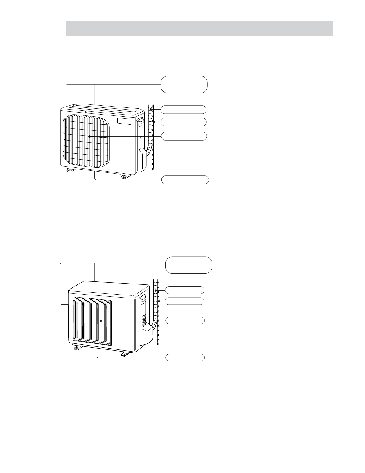
PART NAMES AND FUNCTIONS
Air outlet
Drain outlet
Piping
Drain hose
Air inlet
(back and side)
MU-C08VC
MU-C10VC
MU-C13VC
MU-C18VC
Air inlet
(back and side)
Piping
Drain hose
Air outlet
Drain outlet
MU-GD08ND
MU-GD10ND
MU-GD12ND
Page 4
4
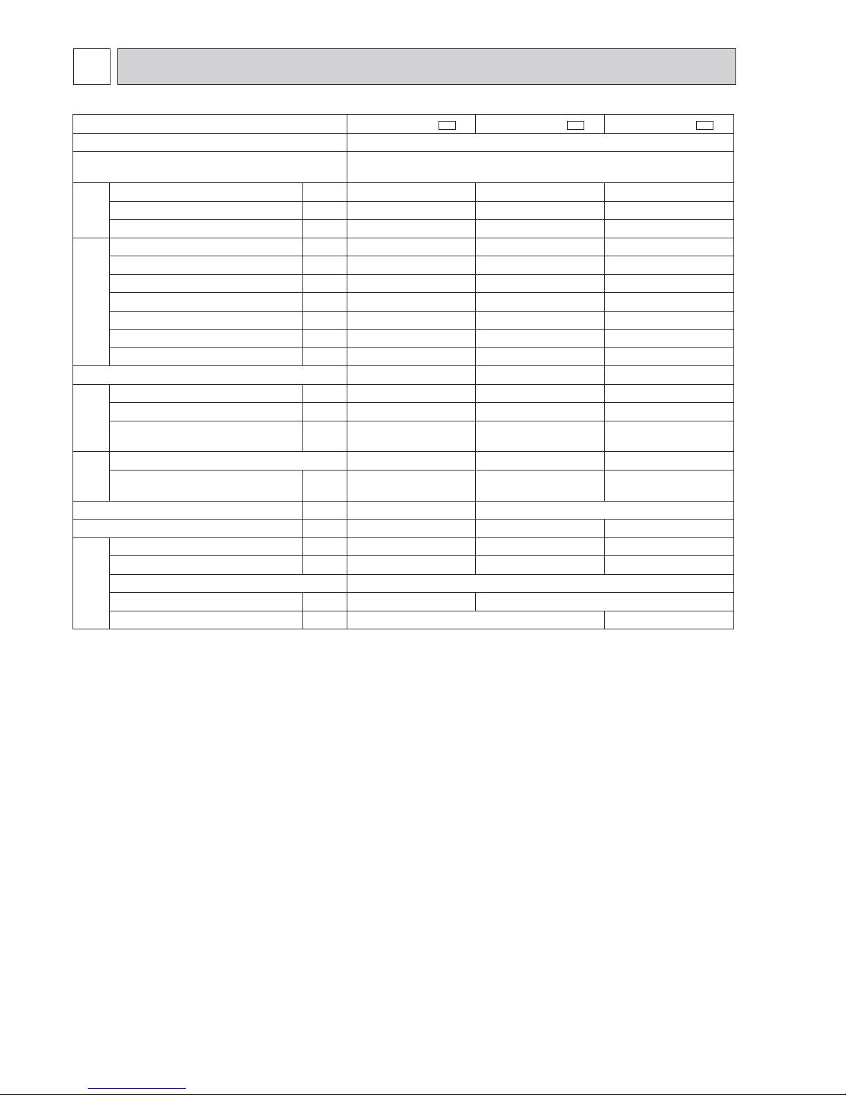
SPECIFICATION
3
Outdoor model
MU-GD08ND -
C1
MU-GD10ND -
C1
MU-GD12ND -
C1
Function Cooling
Power supply
Single phase
220-230V, 60Hz
Capacity
Capacity kW 2.2-2.2 2.9-2.9 3.6-3.6
Dehumidifi cation R/h 0.1 0.45 1.1
Air fl ow K /h 1896-1962 1452-1524 2106-2124
Electrical data
Power outlet A 10 10 10
Running current (Total) A 3.19-3.24 4.31-4.31 5.7-5.7
Power input (Total) W 680-685 930-930 1210-1210
Power factor (Total) % 97-92 98-94 96-92
Starting current A 19 26 40
Compressor motor current A 2.67-2.71 3.86-3.85 5.14-5.13
Fan motor current A 0.330-0.340 0.260-0.270 0.370-0.380
Coeffi cient of performance (C.O.P) 3.24-3.21 3.12-3.12 2.98-2.98
Compressor
Model KS098NARC RH145NHNT RH189NRAT
Output W 500 700 900
Winding
resistance (at 20:)
Ω
C-R 3.54
C-S 4.90
C-R 2.74
C-S 3.78
C-R 1.50
C-S 2.33
Fan
motor
Model RA6V21-BE RA6N21-AB RA6V33-MC
Winding
resistance (at 20:)
Ω
WHT-BLK 252
BLK-RED 278
WHT-BLK 384
BLK-RED 259
WHT-BLK 141
BLK-RED 175
Dimensions WxHxD mm 684x540x255 800x550x285
Weight kg 22 34 35
Special
remarks
Sound level dB 46-47 46-46 50-51
Fan speed rpm 820-830 690-720 980-990
Fan speed regulator 1
Refrigerant fi lling capacity (R22) kg 0.55 1.10
Refrigeration oil (Model) cc 300(NM56) 520(NM56)
NOTE: Test conditions are based on CNS 14464
Cooling : Indoor Dry-bulb temperature 27°C Wet-bulb temperature 19°C
Outdoor Dry-bulb temperature 35°C Wet-bulb temperature 24°C
Refrigerant piping length (one way) 7.5 m
Page 5

5
4
OUTLINES AND DIMENSIONS
20.8
6.441
6
.
98
255
145.5
Service panel
Service port
Air out
Liquid refrigerant pipe joint
Refrigerant pipe (flared) ;6.35
Gas refrigerant pipe joint
Refrigerant pipe (flared) ;9.52
34
04
REQUIRED SPACE
Basically open 100mm or more
without any obstruction in front
and on both sides of the unit.
ero
m
r
o m
m0
5
3
ero
m
ro
mm0
01
erom ro
m
m00
1
erom
ro mm001
Open two sides of left,
right, or rear side.
Air in
Air in
381.5
Drain hole
;33
ro
f
hct
ip t
loB
noitalla
tsni
082~462
0
03
045
072
0
1
5.74
5.
22
17.5
243
Bolt pitch for installation
500
684
61
105
Handle
2 holes 10'16
40
Unit : mm
Unit : mm
0
1
69
800
302.5
500 Bolt pitch for installation
150
22.3
Handle
055
0
82
5.
46
1
5.9
9
170.5
23
Service panel
Service port
582
5.44
3
44
400
Air in
Air out
5.7
1
r
o
f
hct
i
p
tlo
B
no
ital
lats
n
i
52
3
~
4
03
40
Liquid refrigerant pipe joint
Refrigerant pipe (flared) ;6.35
Gas refrigerant pipe joint
Refrigerant pipe (flared)
34
53
2 holes 10'21
REQUIRED SPACE
Basically open 100mm or more
without any obstruction in front
and on both sides of the unit.
erom ro m
m053
erom
ro mm002
erom ro
mm
00
1
e
rom ro mm001
Open two sides of left,
right, or rear side.
Drain hole ;42
Air in
;9.52 (MU-GD10ND)
;12.7 (MU-GD12ND)
MU-GD08ND
MU-GD10ND
MU-GD12ND
Page 6
6
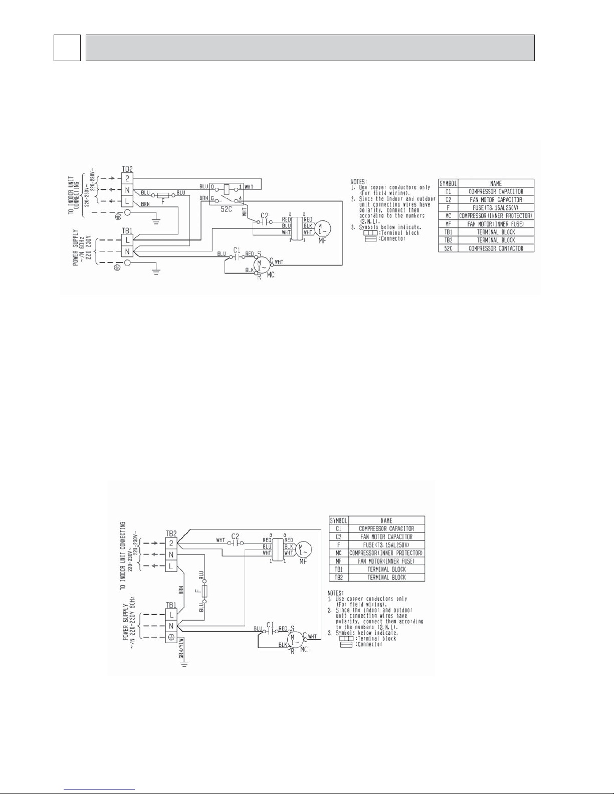
WIRING DIAGRAM
5
MU-C08VC
MU-C10VC
MU-C13VC
MU-GD08ND
MU-GD10ND
Page 7

7
MU-C18VC
REFRIGERANT SYSTEM DIAGRAM
6
Refrigerant flow in cooling
Capillary tube
X3.0 ' X 1.6 ' 650
Compressor
Stop valve
(with service port)
Stop valve
Strainer
#100
Outdoor
heat
exchanger
Refrigerant pipe
(with heat insulator)
X6.35
Refrigerant pipe
X9.52
(with heat insulator)
Flared
connection
Flared
connection
Unit : mm
MU-GD12ND
MU-GD08ND
Page 8

8
MAX.REFRIGERANT PIPING LENGTH
Model
Piping size O.D : mm
Refrigerant piping : m
Gas
X9.52
Liquid
X6.35
20
10
MU-GD08ND-
Max. lengthAMax. height
B
MU-GD10ND-
MU-GD12ND-
X12.7
30
NOTE : Calculation : Xg=15g/m x (Refrigerant piping length (m)-7)
Model
Outdoor unit precharged
Refrigerant piping length (one way)
15m
120
20m
195
7m
0
10m
45
550
1100
30m
-
345
Capillary tube
X3.0 ' X1.6 ' 850
X3.0 ' X1.6 ' 450
Stop valve
(with service port)
Stop valve
Compressor
Strainer
#100
Outdoor heat
exchanger
Refrigerant pipe X6.35
(with heat insulator)
Refrigerant pipe
X9.52 (MU-GD10ND)
X12.7 (MU-GD12ND)
(with heat insulator)
Flared
connection
Flared
connection
Refrigerant flow in cooling
MU-C18VC
C1
C1
C1
MU-GD10ND-
C1
MU-GD12ND-
C1
MU-GD08ND-
C1
Indoor
unit
Max. Height
B
Outdoor unit
Refrigerant Piping
Max. Length
A
MAX.HEIGHT DIFFERENCE
ADDITIONAL REFRIGERANT CHARGE(R22 : g)
MU-GD10ND
MU-GD12ND
Model
Refrigerant piping : m Piping size O.D : mm
Max. length
A
Max. height
B
Gas Liquid
MU-GD08ND -
C1
20 10
ø9.52
ø6.35
MU-GD10ND -
C1
MU-GD12ND -
C1
ø12.7
Model
Outdoor unit
precharged
Refrigerant piping length (one way)
7m 10m 15m 20m
MU-GD08ND -
C1
550
0 45 120 195
MU-GD10ND -
C1
110 0
MU-GD12ND -
C1
(MU-GD10ND - C1)
(MU-GD12ND - C1)
Page 9

9
PERFORMANCE CURVES7
The standard data contained in these specifications apply only to the operation of the air conditioner under normal conditions.
Since operating conditions vary according to the areas where these units are installed. The following information has been
provided to clarify the operating characteristics of the air conditioner under the conditions indicated by the performance curve.
(1) GUARANTEED VOLTAGE
198 ~ 253V, 60Hz
(2) AIR FLOW
Air flow should be set at MAX.
(3) MAIN READINGS
(1) Indoor intake air wet-bulb temperature : °CWB
(2) Indoor outlet air wet-bulb temperature : °CWB
(3) Outdoor intake air dry-bulb temperature : °CDB
(4) Total input: W
Indoor air wet/dry-bulb temperature difference on the left side of the chart on next page shows the difference between the
indoor intake air wet/dry-bulb temperature and the indoor outlet air wet/dry-bulb temperature for your reference at service.
MU-C08VC MU-C10VC MU-C13VC MU-C18VC
Wet and dry-bulb
thermometers
Wet and dry-bulb
thermometers
How to measure the indoor air wet/dry-bulb temperature difference
1. Attach at least 2 sets of wet and-dry-bulb thermometers to the indoor air intake as shown in the figure, and at least 2 sets
of wet and dry-bulb thermometers to the indoor air outlet. The thermometers must be attached to the position where air
speed is high.
2. Attach at least 2 sets of wet and dry-bulb thermometers to the outdoor air intake.
Cover the thermometers to prevent direct rays of the sun.
3. Check that the air filter is cleaned.
4. Open windows and doors of the room.
5. Press the EMERGENCY OPERATION switch once to start the EMERGENCY COOL MODE.
6. When system stabilizes after more than 15 minutes, measure temperature and take an average temperature.
7. 10 minutes later, measure temperature again and check that the temperature does not change.
INDOOR UNIT OUTDOOR UNIT
Indoor intake air WB temperature ()
Outdoor intake air DB temperature ()
Indoor intake air WB temperature ()
Outdoor intake air DB temperature ()
3.8
3.4
4.3
5.6
5.1
4.7
5.8
5.1
6.4
8.5
7.8
7.1
4.8
4.3
5.4
7.0
6.5
5.9
MS-GD08ND-
C1
MU-GD08ND-C1MS-GD12ND-
C1
MU-GD12ND-
C1
MS-GD10ND-
C1
MU-GD10ND-
C1
MU-GD08ND MU-GD10ND MU-GD12ND
Page 10

10
Both indoor and outdoor units are under the same temperature/humidity condition.
OUTDOOR LOW PRESSURE AND OUTDOOR UNIT CURRENT
COOL operation
Air flow should be set at MAX.
Dry-bulb temperature ()
Relative humidity (%)
20
50
25
60
30 70
The unit of pressure has been changed to MPa on the international system of units(SI unit system).
The conversion factor is : 1(MPa [Gauge]) =10.2(kgf/C[Gauge])
15 20
50
25
60
3070 35()
(%)
0.4
0.5
0.6
0.7
0.8
4.0
5.0
6.0
7.0
8.0
9.0
0.9
15 20
50
25
60
30
70
35()
(%)
2.0
2.5
3.0
3.5
4.0
erusser
p
wol
roodtuO
)
A
(
tnerruc tinu roo
d
t
u
O
(kgf/& [Gauge])(MPa [Gauge])
Ambient temperature (˚C)/Ambient humidity (%)
Ambient temperature (˚C)/Ambient humidity (%)
230V
220V
0.4
0.5
0.6
0.7
0.8
1
2
3
4
0.8
0.7
0.6
0.5
0.4
15 20
50
25
60
3070 35()
(%)
15 20
50
25
60
3070 35()
(%)
Ambient temperature (˚C)/Ambient humidity (%)
erusserp wol roodtuO
Ambient temperature (˚C)/Ambient humidity (%)
)A( tner
r
uc tinu roodtuO
(kgf/& [Gauge])(MPa [Gauge])
230V
220V
MU-GD10ND MU-GD10ND
MU-GD08ND MU-GD08ND
0.3
0.4
0.5
0.6
0.7
4
5
6
7
0.7
0.6
0.5
0.4
0.3
15 20
50
25
60
3070 35()
(%)
15 20
50
25
60
3070 35()
(%)
Ambient temperature (˚C)/Ambient humidity (%)
erusserp wol roodtuO
Ambient temperature (˚C)/Ambient humidity (%)
)A( tnerruc tinu roo
d
tuO
(kgf/& [Gauge])(MPa [Gauge])
220V
230V
220V
230V
MU-GD12ND MU-GD12ND
Page 11

11
8-2. Trouble criterion of main parts
$
$
:INNER PROTECTOR
TROUBLESHOOTING8
8-1. Cautions on troubleshooting
1. Before troubleshooting, check the following:
1) Check the power supply voltage.
2) Check the indoor/outdoor connecting wire for mis-wiring.
2. Take care of the following during servicing
1) Before servicing the air conditioner, be sure to turn OFF the main unit first with the remote controller, and then after
confirming the horizontal vane is closed, turn OFF the breaker and / or disconnect the power plug.
2) Be sure to turn OFF the power supply before removing the front panel,
the cabinet, the top panel and the electronic control P.C. board.
3) When removing the electronic control P.C. board, hold the edge of the
board with care NOT to apply stress on the components.
4) When connecting or disconnecting the connectors, hold the housing of the
connector. DO NOT pull the lead wires.
MU-C08VC MU-C10VC MU-C13VC MU-C18VC
Lead wiring
Housing point
Outdoor fan
motor (MF)
INNER FUSE
MU-GD08/GD12ND-
126&2 OPEN
MU-GD10ND-
145 OPEN
Measure the resistance between the terminals with a tester.
(Coil wiring temperature -10oC ~ 40oC)
WHT
RED
BLK
AUX.
MAIN
FUSE
Compressor (MC)
INNER
PROTECTOR
MU-GD08ND-
155&5 OPEN
90&10 CLOSE
MU-GD10/GD12ND-
150&5 OPEN
90&10 CLOSE
Part name
Check method and criterion
Measure the resistance between the terminals with a tester.
(Coil wiring temperature -10oC ~ 40oC)
Figure
RED
WHT
BLK
P
C
SR
C1
C1
C1
C1
MU-GD08ND MU-GD10ND MU-GD12ND
MU-GD08ND
MU-GD10ND
MU-GD12ND
Color of
lead wire
Normal
MU-GD08ND-
C1
MU-GD10ND-
C1
MU-GD12ND-
C1
C-R 3.12 ~ 3.82 Ω 2.41 ~ 2.96 Ω 1.32 ~ 1.62 Ω
C-S 4.32 ~ 5.29 Ω 3.33 ~ 4.08 Ω 2.05 ~ 2.52 Ω
Color of
lead wire
Normal
MU-GD08ND -
C1
MU-GD10ND - C1 MU-GD12ND -
C1
WHT-BLK 222 ~ 272 Ω 338 ~ 415 Ω 124 ~ 153 Ω
BLK-RED 245 ~ 300 Ω 228 ~ 280 Ω 154 ~ 189 Ω
Page 12

12
DISASSEMBLY INSTRUCTIONS
9
OPERATING PROCEDURE
PHOTOS
Photo 1
1. Removing the cabinet
(1) Remove the screws fixing the top panel. (See Photo 1.)
(2) Remove the top panel. (See Photo 1.)
(3) Remove the screw fixing the service panel. (See Photo 2.)
(4) Pull down the service panel and remove it. (See Photo 2.)
(5) Remove the screws fixing the cabinet.
(6) Remove the cabinet.
(7)
Disconnect the power supply and indoor/outdoor connecting wire.
(8) Remove the screws fixing the back panel.
(9) Remove the back panel.
Screws of
the cabinet
(1) Slide the sleeve and check if there is a locking lever or not.
(2) The terminal with this connector has the
locking mechanism.
Slide the sleeve.
Pull the terminal while
pushing the locking
lever.
Hold the sleeve, and
pull out the terminal
slowly.
The terminal which has the locking mechanism can be detached as shown below.
There are two types ( Refer to (1) and (2)) of the terminal with locking mechanism.
The terminal without locking mechanism can be detached by pulling it out.
Check the shape of the terminal before detaching.
<"Terminal with locking mechanism" Detaching points>
Connector
Sleeve
Locking lever
Photo 2
Screw of the
service panel
Direction to
remove
Hooks
Service
panel
Screw of
the top panel
Screws
of the
top panel
9-1. MU-C08VC MU-C10VC MU-C13VC
MU-GD08ND
Page 13

13
3. Removing the propeller and the outdoor fan motor
(1) Remove the cabinet. (Refer to 1.)
(2) Remove the propeller nut and the propeller.
NOTE : Loose the propeller in the rotating direction for
removal.
When attaching the propeller, align the mark on the
propeller and the motor shaft cut section.
Set the propeller in position by using the cut on the shaft
and the mark on the propeller.
(3) Remove the lead clamps and outdoor fan motor lead wires.
(4) Remove the screws fixing the outdoor fan motor.
(5) Remove the outdoor fan motor.
Photo 4
Propeller
Propeller
nut
Outdoor
fan motor
Set screws of the
outdoor fan motor
Hook
Relay panel
Outdoor fan motor lead wires
Set screws of the
outdoor fan motor
OPERATING PROCEDURE PHOTOS
2. Removing the electrical parts
(1) Remove the service panel and the cabinet.(Refer to 1.)
(2) Remove the following parts.
•Compressor capacitor (C1)
•Outdoor fan capacitor (C2)
•Terminal block (TB)
•Compressor contactor (52C)
Photo 3
Outdoor fan
capacitor
(C2)
Terminal
block (TB2)
Compressor
capacitor
(C1)
Lead clamp
Connector
Terminal
block(TB1)
Compressor
contactor
(52C)
x
xx
x
x
x
xx
x
xx
xx
xxx
x
x
x
x
xx
xx
xx
xxx
xx
xxx
xx
x
x
x
x
x
x
x
x
x
x
xxxx
x
x
xx
x
x
xx
x
x
x
x
x
x
x
xx
x
x
xx
x
x
x
x
xx
0
8
2
1
Model and type name
OMRON
G7L-1A-TUB-07
NOTE : When attaching compressor contactor (52C)
to relay panel, make sure that the side with
printed letters is facing upward.
4
6
0
1
Earth screw of
indoor/
outdoor
connecting wire
Earth screw of
power supply
Page 14

14
OPERATING PROCEDURE PHOTOS
4. Removing the compressor
(1) Remove the cabinet. (Refer to 1.)
(2) Remove the soundproof felt.
(3) Remove the screws fixing the relay panel.
(4) Remove the terminal cover.
(5) Pull out the lead wires from the glass terminal of the com-
pressor.
(6) Recover gas from the refrigerant circuit.
NOTE : Recover gas from the pipes until the pressure gauge
shows 0 kg/cm
2
(0MPa).
(7) Disconnect the welded part of the suction pipe and
discharge pipe.
(8) Remove the nuts fixing the compressor.
(9) Remove the compressor.
Photo 5
Compressor
Discharge
pipe
Compressor set nuts
(3 places)
Terminal
cover
Suction
pipe
MU-C08/10VC
Photo 6
Compressor
Discharge
pipe
Compressor set nuts
(3 places)
Terminal
cover
Suction
pipe
MU-C13VC
Page 15

15
2. Removing the electrical parts
(1) Remove the service panel and the cabinet. (Refer to 1.)
(2) Remove the following parts.
•Compressor capacitor (C1)
•Outdoor fan capacitor (C2)
•Terminal block (TB)
•Compressor contactor (52C)
OPERATING PROCEDURE PHOTOS
9-2. MU-C18VC
Photo 4
1. Removing the cabinet
(1) Remove the screws fixing the top panel. (See Photo 2 and
3.)
(2) Remove the top panel. (See Photo 3.)
(3) Remove the screw fixing the service panel. (See Photo 3.)
(4) Pull down the service panel and remove it. (See Photo 3.)
(5) Remove the screws fixing the cabinet.
(6) Remove the cabinet.
(7) Disconnect the indoor/outdoor connecting wire.
(8) Remove the screws fixing the back panel.
(9) Remove the back panel.
Photo 1
Screws of the cabinet
Screws of the front panel and motor support
Photo 3
Screws of the
top panel
Service
panel
Screw of the
cabinet
Direction
to remove
Hooks
Screw of the
service panel
Screws of
the cabinet
Photo 2
Screws of the
top panel
MU-GD10ND MU-GD12ND
MU-GD10ND
Lead clamp
Compressor
capacitor (C1)
Outdoor fan
capacitor (C2)
Connector
Terminal
block(TB1)
Earth screw of
power supply
Terminal
block (TB2)
Earth screw of indoor/
outdoor connecting wire
Page 16

16
PHOTOS
OPERATING PROCEDURE
3. Removing propeller and the outdoor fan motor
(1) Remove the cabinet. (Refer to 1.)
(2) Remove the propeller nut and remove the propeller.
NOTE : Loose the propeller in the rotating direction for
removal.
When attaching the propeller, align the mark on the
propeller and the motor shaft cut section.
Set the propeller in position by using the cut on the
shaft and the mark on the propeller.
(3) Disconnect the connector and remove the lead clamps and
outdoor fan motor lead wires.
(4) Remove the screws fixing the outdoor fan motor.
(5) Remove the outdoor fan motor.
Photo 5
MU-GD12ND
MU-GD10ND
MU-GD12ND
Relay panel
Hook
Outdoor fan motor
lead wires
Set screws of the
outdoor fan motor
Propeller
Set screws of the
outdoor fan motor
Propeller nut
Outdoor
fan motor
Set screws of the
outdoor fan motor
Propeller nut
Relay panel
Hook
Outdoor fan motor
lead wires
Set screws of the
outdoor fan motor
Propeller
Outdoor
fan motor
Lead clamp
Compressor
capacitor (C1)
Outdoor fan
capacitor (C2)
Connector
Terminal
block(TB1)
Terminal
block (TB2)
Compressor
contactor
(52C)
Page 17

17
PHOTOS
OPERATING PROCEDURE
4. Removing the compressor
(1) Remove the cabinet. (Refer to 1.)
(2) Remove the relay panel.
(3) Remove the soundproof felt.
(4) Remove the terminal cover.
(5) Pull out the lead wires from the glass terminal of the com-
pressor.
(6) Recover gas from the refrigerant circuit.
NOTE : Recover gas from the pipes until the pressure gauge
shows 0 kg/cm
2
(0MPa).
(7) Disconnect the welded part of the suction pipe and dis-
charge pipe.
(8) Remove the nuts fixing the compressor and the compres-
sor.
Glass
terminal
Compressor
Suction pipe
Discharge pipe
Compressor
nuts
Photo 6
MU-GD10ND
Glass
terminal
Discharge
pipe
Suction
pipe
Compressor nuts
(3 places)
Compressor
MU-GD12ND
Page 18

Page 19

Page 20

MITSUBISHI ELECTRIC CONSUMER PRODUCTS (THAILAND) CO., LTD.
AMATA NAKORN INDUSTRIAL ESTATE
700/406 MOO 7, TAMBON DON HUA ROH,
AMPHUR MUANG, CHONBURI 20000 THAILAND
Made in Thailand
New publication, effective Apr. 2008
Specifications subject to change without notice.
HEAD OFFICE: TOKYO DENKI BLDG., 2-7-3, MARUNOUCHI, CHIYODA-KU, TOKYO100-8310, JAPAN
TM
 Loading...