

Mitsubishi Electric MU-A08ND-c1, MU-A12ND-c1, MU-A15N-c1, DMU-A15ND-c2, MU-A08ND-c2 Service Manual
...
SPLIT-TYPE, AIR CONDITIONERS
OUTDOOR UNIT
SERVICE MANUAL
Wireless type
Models
Revision:B
• MU-A10ND - has been added.
• RoHS PARTS LIST has been added.
Please void OB403 REVISED EDITION-A.
C2
No. OB403
REVISED EDITION-B
MU-A08NDMU-A08NDMU-A10NDMU-A10NDMU-A12NDMU-A15NDMU-A15ND-
MU-A10ND
MU-A12ND
C1
C2
C1
C2
C1
C1
C2
Indoor unit service manual
MS-A•ND Series (OB402)
CONTENTS
1. TECHNICAL CHANGES ····································2
2. PART NAMES AND FUNCTIONS······················3
3. SPECIFICATION·················································4
4. OUTLINES AND DIMENSIONS·························5
5. WIRING DIAGRAM ············································8
6. REFRIGERANT SYSTEM DIAGRAM················9
7. PERFORMANCE CURVES······························12
8. TROUBLESHOOTING······································15
9. DISASSEMBLY INSTRUCTIONS ····················17
10. PARTS LIST······················································25
11. RoHS PARTS LIST···········································29
12. OPTIONAL PARTS ···········································33
TM
NOTE:
This service manual describes technical data of outdoor units.
RoHS compliant products have <G> mark on the spec name plate.
For servicing of RoHS compliant products, refer to the RoHS Parts List.
Revision A:
• MU-A08ND - and MU-A15ND - have been added.
C2C2
Revision B:
• MU-A10ND - has been added.
• RoHS PARTS LIST has been added.
C2
TECHNICAL CHANGES1
MU-09SN - ➔ MU-A08ND -
1. Compressor has been changed. (RH-130NGDT ➔ 2R10S3R236A-6B)
2. Outdoor fan motor has been changed. (RA6N23-AA ➔ RA6N33-AA)
3. Compressor capacitor has been changed.
4. Outdoor fan motor capacitor has been changed.
MU-10SN - ➔ MU-A10ND -
1. Outdoor unit model has been changed.
•Valve cover has been added.
•Dimension has been changed. (780Wo540Ho255D ➔ 800Wo550Ho285D)
2. Compressor has been changed. (RH145NGCT ➔ RH145NHNT)
3. Outdoor fan motor has been changed. (RA6N33-AA ➔ RA6N21-AB)
4. Compressor capacitor has been changed.
5. Outdoor fan motor capacitor has been changed.
6. Outdoor heat exchanger has been changed. ([9.52 L-Bend ➔ [7 Flat)
C1C2
C1C2
MU-12SN - ➔ MU-A12ND -
1. Outdoor unit model has been changed.
•Valve cover has been added.
•Dimension has been changed. (780Wo540Ho255D ➔ 800Wo550Ho285D)
2. Compressor has been changed. (RH167NHDT ➔ RH174NHNT)
3. Outdoor fan motor has been changed. (RA6N33-AA ➔ RA6N30-BA)
4. Compressor capacitor has been changed.
5. Outdoor fan motor capacitor has been changed.
6. Outdoor heat exchanger has been changed. ([9.52 L-Bend ➔ [7 Flat)
MU-15SN - ➔ MU-A15ND -
1. Compressor has been changed. (RH-207NHDT ➔ RH207NRAT)
2. Outdoor fan motor has been changed. (RN6N50-BA ➔ RA6V60-MA)
3. Compressor capacitor has been changed.
4. Outdoor fan motor capacitor has been changed.
MU-A08ND - ➔ MU-A08ND MU-A15ND - ➔ MU-A15ND -
1. Valve cover has been added.
MU-A10ND - ➔ MU-A10ND -
1. Outdoor heat exchanger has been changed.
2. Capillary tube has been changed.
C1C2
C1C2
C2C1
C2C1
C2C1
2
2
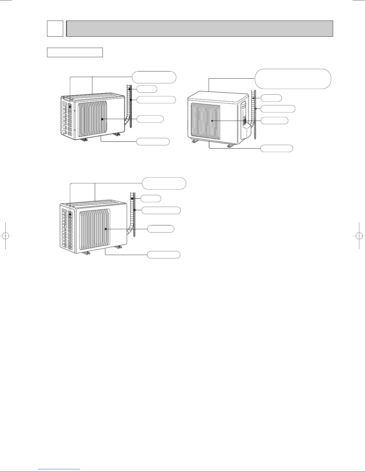
Air inlet
Piping
Drain hose
Air outlet
Drain outlet
(back and side)
Air inlet
Piping
Drain hose
Air outlet
Drain outlet
back and side : MU-A10ND
back : MU-A12ND
()
Air inlet
Piping
Drain hose
Air outlet
Drain outlet
(back and side)
PART NAMES AND FUNCTIONS
OUTDOOR UNIT
MU-A08ND
MU-A15ND
MU-A10ND
MU-A12ND
3
3
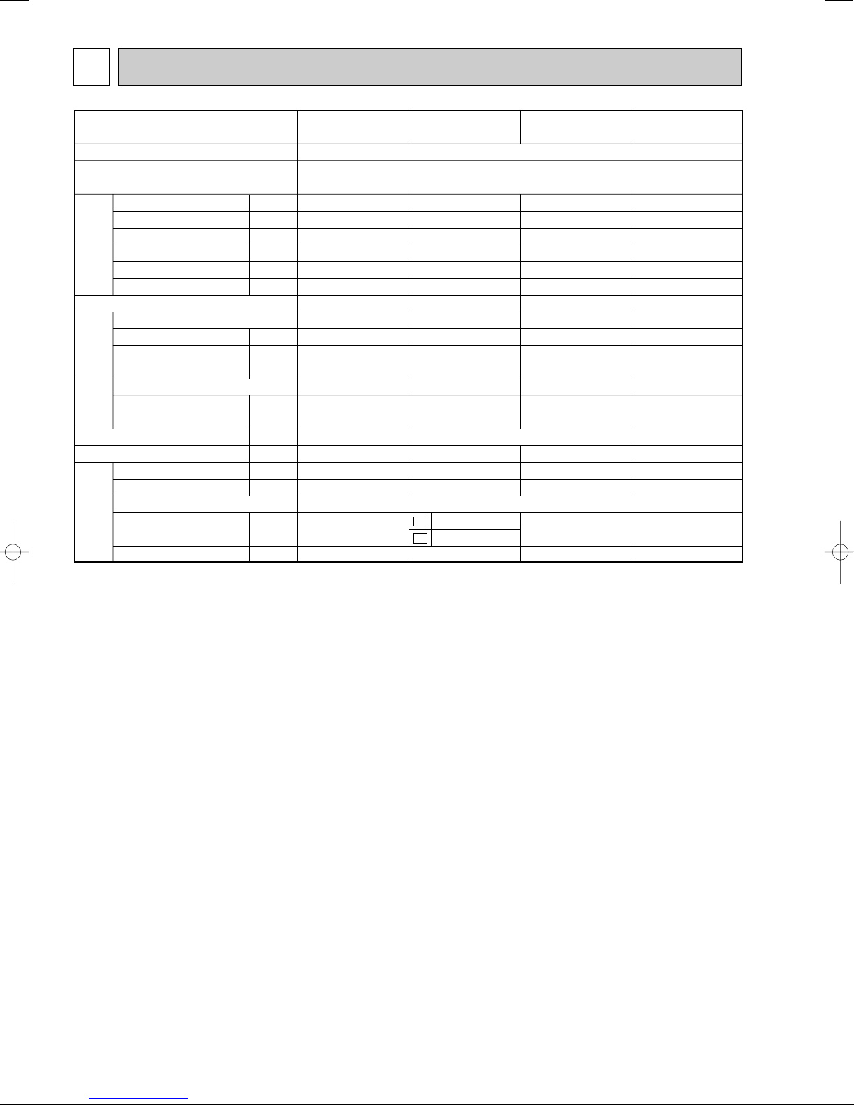
Outdoor model
Function
Power supply
Coefficient of performance (C.O.P)
Capacity
Dehumidification
Air flow
Starting current
Compressor motor current
Fan motor current
Model
Output
Winding
resistance (at 20:)
Model
Winding
resistance (at 20:)
Dimensions WOHOD
Weight
Sound level
Fan speed
Fan speed regulator
Refrigerant filling
capacity (R22)
Refrigeration oil (Model)
kW
R/h
K /h
A
A
A
W
"
"
mm
kg
dB
rpm
kg
cc
MU-A15ND
4.0
1.8
2280
35
5.62
0.5
2.97
RH207NRAT
1000
C-R 1.50
C-S 2.33
RA6V60-MA
WHT-BLK 116
BLK-RED 111
850o605o290
42
52
865
1.6
520 (MS56)
Electrical
data
Fan
motor
Special
remarks
Compressor
Capacity
MU-A08ND
2.2
0.5
1656
19
2.39
0.36
3.44
2R10S3R236A-6B
470
C-R 4.09
C-S 5.58
RA6N33-AA
WHT-BLK 150
BLK-RED 265
780o540o255
28
45
700
0.8
260 (ATM0S M60)
MU-A10ND
2.9
1.2
1896
26
3.86
0.26
3.12
RH145NHNT
700
C-R 2.74
C-S 3.78
RA6N21-AB
WHT-BLK 384
BLK-RED 259
32
46
820
0.6
1.1
300 (MS56)
1
MU-A12ND
3.6
1.7
1884
30
4.95
0.35
3.08
RH174NHNT
800
C-R 2.19
C-S 3.3
RA6N30-BA
WHT-BLK 312
BLK-RED 255
34
47
850
1.2
520 (MS56)
Cooling
Single phase
220-230V, 60Hz
800o550o285
C1
C2
SPECIFICATION
NOTE: Test conditions are based on CNS14464, ISO5151.
Cooling : Indoor DB27°C / WB19°C
Outdoor DB35°C / WB24°C
Indoor-Outdoor piping length: 5 m
4
320
25
43-
35
-
104
320
285
255
Service panel
Gas refrigerant
pipe joint
Refrigerant pipe
(flared) [9.52
Liquid refrigerant
pipe joint
Refrigerant pipe
(flared) [6.35
Airout
Air in
Air in
Service port
155
90
74
260
10
780
500
122
40
540
109
32
110
147
Drainage
3 holes [33
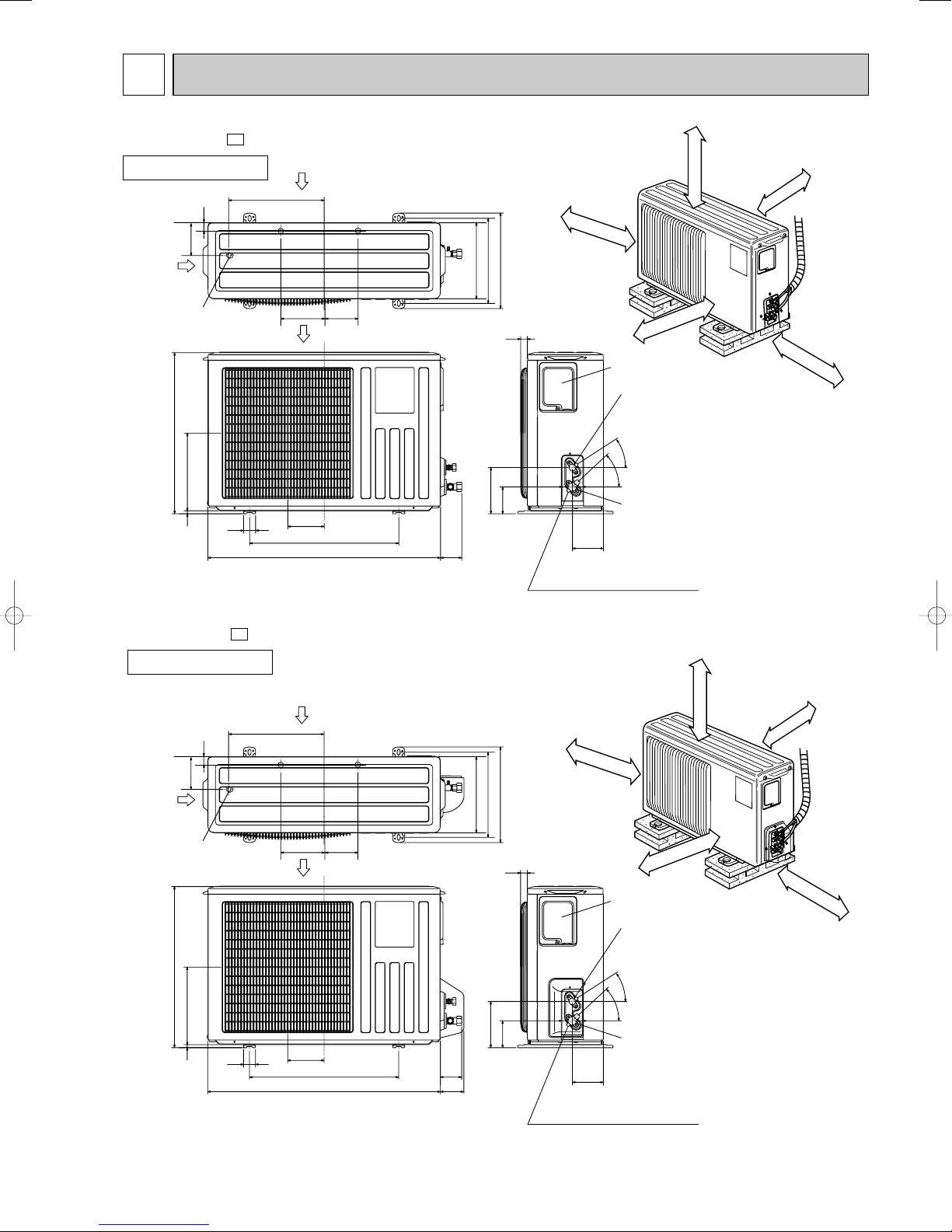
OUTLINES AND DIMENSIONS4
100mm or more
100mm or more
100mm or more
350mm or more
REQUIRED SPACE
400mm or more
MU-A08ND -
C1
OUTDOOR UNIT
Unit : mm
MU-A08ND -
C2
OUTDOOR UNIT
Air in
320
32
109
Air in
Drainage
3 holes [33
540
260
10
40
147
Airout
122
500
780
110
255
74
81
320
285
25
155
90
5
REQUIRED SPACE
100mm or more
400mm or more
Service panel
Liquid refrigerant
pipe joint
Refrigerant pipe
(flared) [6.35
-
35
43-
Gas refrigerant
pipe joint
104
Refrigerant pipe
(flared) [9.52
Service port
100mm or more
Unit : mm
100mm or more
350mm or more
100mm or more
REQUIRED SPACE
350mm or more
500mm or more
100mm or more
100mm or more
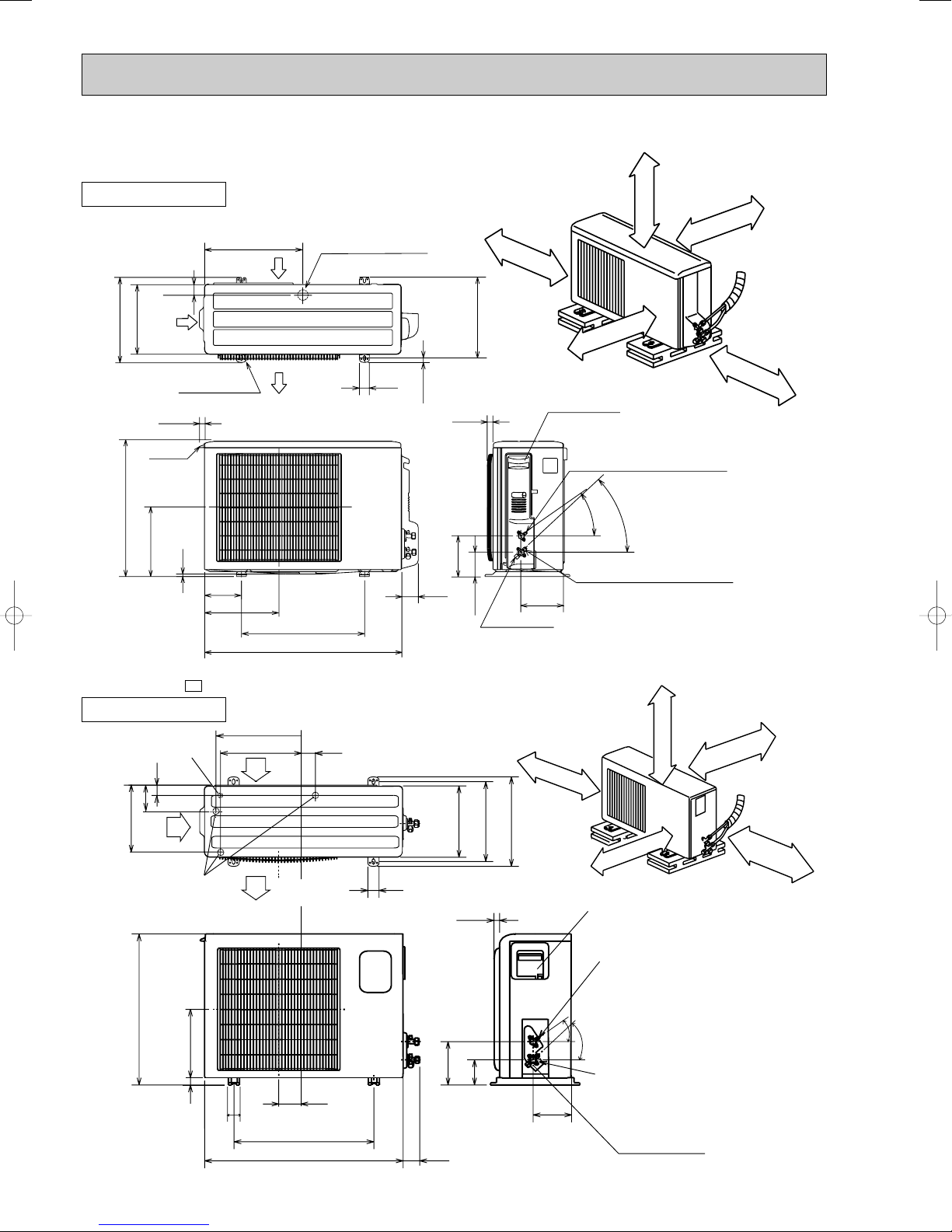
30
Service panel
Service port
605
292
20
50
183
500
850
74
157
100
161
Gas refrigerant
pipe joint
Refrigerant pipe (flared)
[12.7
Liquid refrigerant
pipe joint
Refrigerant pipe (flared)
[6.35
30
o
35
o
Drainage
3 holes [33
Air out
Air in
Air in
248
35
350
50
290
310
345
20
355
90
Drainage
hole [16.2
MU-A10ND
43-
35-
10
69
800
302.5
500
150
22.3
Handle
550
280
164.5
99.5
170.5
23
Service panel
Service port
285
344.5
44
400
Air in
Air out
Air in
(MU-A
10ND)
17.5
Bolt pitch for
installation
304~325
40
Liquid refrigerant pipe joint
Refrigerant pipe (flared) [6.35
Gas refrigerant pipe joint
Refrigerant pipe (flared) [9.52
(MU-A10ND)
Refrigerant pipe (flared) [12.7
(MU-A12ND)
2 holes 10X21
Basically open 100mm
or more without any
obstruction in front and
on both sides of the unit.
350mm or more
200mm or more
100mm or more
100mm or more
Open two sides of left,
right, or rear side.
Drain hole [42
REQUIRED SPACE
MU-A12ND
OUTDOOR UNIT
Unit : mm
MU-A15ND -
C1
OUTDOOR UNIT
6
Unit : mm
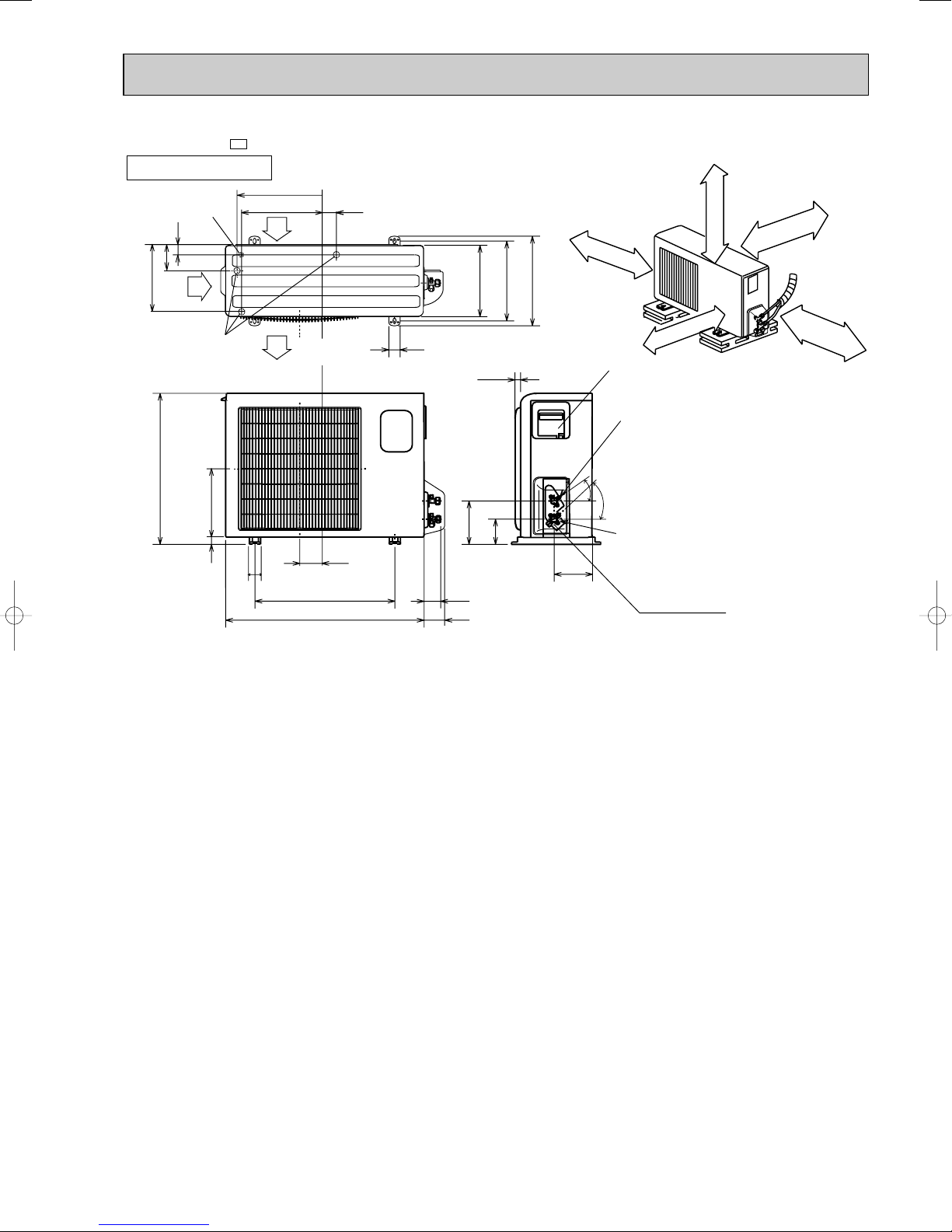
MU-A15ND -
C2
OUTDOOR UNIT
Drainage
hole [16.2
35
90
248
Air in
Drainage
3 holes [33
605
292
20
50
355
350
Air in
Air out
183
500
850
20
50
74
81
290
157
30
310
100
REQUIRED SPACE
100mm or more
345
30
161
100mm or more
500mm or more
Service panel
Liquid refrigerant
pipe joint
Refrigerant pipe (flared)
o
[6.35
o
35
Gas refrigerant
pipe joint
Refrigerant pipe (flared)
[12.7
Service port
Unit : mm
100mm or more
350mm or more
7
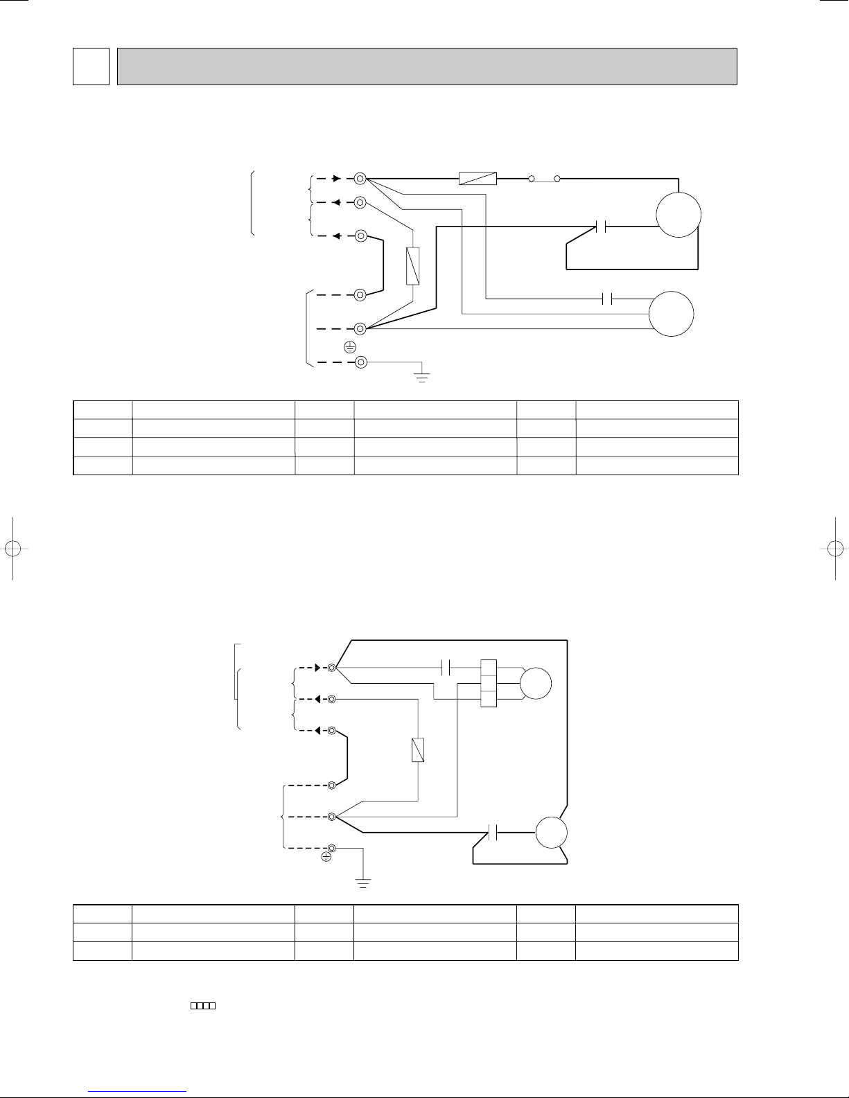
5
SYMBOL
C1
C2
F1
SYMBOL
F2
MC
MF
SYMBOL
TB1,TB2
51C
NAME
NAME NAME
COMPRESSOR CAPACITOR
OUTDOOR FAN CAPACITOR
FUSE (3.15A)
FUSE (20A)
COMPRESSOR (OUTER PROTECTOR)
OUTDOOR FAN MOTOR (INNER PROTECTOR)
TERMINAL BLOCK
OVERCURRENT RELAY
TB1
TB2
GRN/YLW
N
L
2
N
L
MF
C2
C1
S
RED
MC
R
C
BLK
POWER SUPPLY
220-230V ~/N 60Hz
CONNECTING
TO INDOOR UNIT
BRN
BLU
BLU
BLU
14
51C
WHT
WHT
BLK
WHT
RED
WHT
F1
F2
220-230V~
220-230V~
SYMBOL
C1
C2
SYMBOL
F
MC
SYMBOL
MF
TB1,TB2
NAME
NAME NAME
COMPRESSOR CAPACITOR
OUTDOOR FAN CAPACITOR
FUSE (3.15A)
COMPRESSOR (INNER PROTECTOR)
OUTDOOR FAN MOTOR (INNER FUSE
)
TERMINAL BLOCK
N
L
TB1
L
N
2
TB2
C2
220-230V~
C1
BLU BLU
WHT
WHT
RED
R
MC
C
WHT
CONNECTING
BLK
S
BLU
1
3
2
MF
WHT
BLK
RED
GRN/YLW
RED
POWER SUPPLY
220-230V
~/N 60Hz
220-230V~
F
BRN
BLU
TO INDOOR
UNIT
WIRING DIAGRAM
MU-A08ND
NOTE:1. About the indoor side electric wiring refer to the indoor unit electric wiring diagram for servicing.
2.Use copper conductors only. (For field wiring)
3. Symbols below indicate.
/: Terminal block
MU-A10ND
MU-A12ND
NOTE:1. About the indoor side electric wiring refer to the indoor unit electric wiring diagram for servicing.
2.Use copper conductors only. (For field wiring)
3. Symbols below indicate.
/: Terminal block :Connector
8
Strainer
#100
MU-A15ND
SYMBOL
C1
C2
SYMBOL
F
MC
SYMBOL
MF
TB1,TB2
NAME
NAME NAME
COMPRESSOR CAPACITOR
OUTDOOR FAN CAPACITOR
FUSE (3.15A)
COMPRESSOR (INNER PROTECTOR)
OUTDOOR FAN MOTOR (INNER PROTECTOR)
TERMINAL BLOCK
CONNECTING
TO INDOOR UNIT
R
S
2
N
L
TB2
RED
ORN
BLU
WHT
GRN/YLW
C2
RED
MF
BLK
4
WHT
ORN
321
WHT
BLK
L
N
TB1
BRN
BLU
C1
RED
C
MC
BLU
POWER SUPPLY
220-230V ~/N 60Hz
F
BLU
220-230V~
220-230V~
NOTE:1. About the indoor side electric wiring refer to the indoor unit electric wiring diagram for servicing.
2.Use copper conductors only. (For field wiring)
3. Symbols below indicate.
/: Terminal block :Connector
6
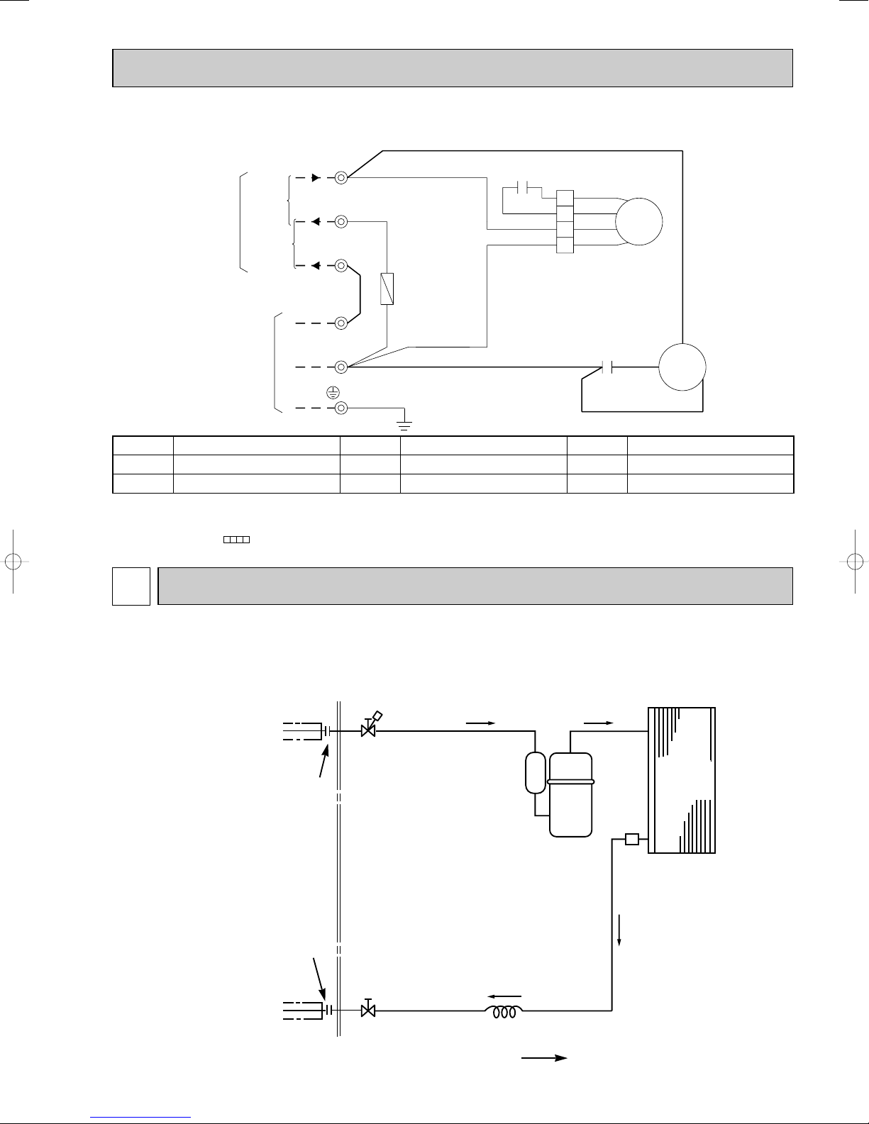
REFRIGERANT SYSTEM DIAGRAM
MU-A08ND
Refrigerant pipe
(Option) [9.52
(with heat insulator)
Flared connection
Refrigerant pipe
(Option) [6.35
(with heat insulator)
Flared connection
Stop valve
(with service port)
Stop valve
9
Compressor
Capillary tube
[3.0x[1.4x800
Outdoor
heat
exchanger
Refrigerant flow in cooling
Unit: mm
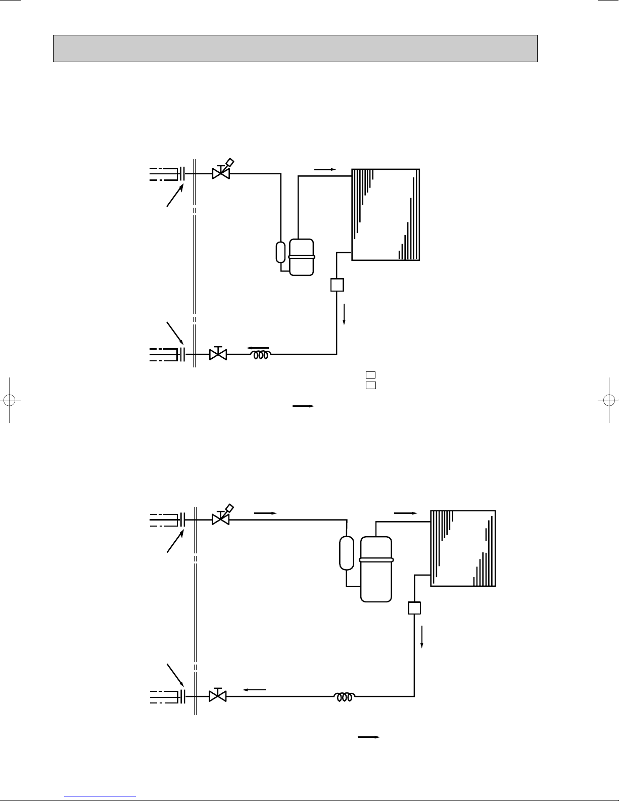
Capillary tube
{3.0 x {1.6x750
Stop valve
(with service port)
Stop valve
Compressor
Strainer
#100
Outdoor heat
exchanger
Refrigerant flow in cooling
Refrigerant pipe
(Option){6.35
(with heat insulator)
Refrigerant pipe
(Option){12.7
(with heat insulator)
Flared
connection
Flared
connection
MU-A10ND
Refrigerant flow in cooling
Capillary tube
{3.0 x { 1.6 x 500 (MU-A10ND - )
{3.0 x { 1.6 x 850 (MU-A10ND - )
Compressor
Stop valve
(with service port)
Stop valve
Strainer
#100
Outdoor
heat
exchanger
C1
C2
Refrigerant pipe
(Option){6.35
(with heat insulator)
Refrigerant pipe
(Option){9.52
(with heat insulator)
Flared
connection
Flared
connection
Unit: mm
MU-A12ND
Unit: mm
10

MU-A15ND
Strainer
#100
Muffler
Unit: mm
Refrigerant pipe
(Option) [12.7
(with heat insulator)
Flared connection
Flared connection
Refrigerant pipe
(Option) [6.35
(with heat insulator)
Stop valve
(with service port)
Outdoor
heat
exchanger
Compressor
Stop valve
Capillary tube
[3.0x[1.8x700
Refrigerant flow in cooling
11
 Loading...