

Mitsubishi Electric MU-A09WA, MU-A12WA Service Manual
SPLIT-TYPE AIR CONDITIONERS
OUTDOOR UNIT
HFC
utilized
R410A
SERVICE MANUAL
Wireless type
Models
MU-A09WA
MU-A12WA
Revision : A
● MU-A12WAPlease void OB449.
1
has been added.
No. OB449
REVISED EDITION-A
MU-A12WA-
1
MU-A09WA
MU-A12WA
Indoor unit service manual
MS-A•WA Series (OB448)
CONTENTS
1. TECHNICAL CHANGES ····································2
2. PART NAMES AND FUNCTIONS······················5
3. SPECIFICATION·················································6
4. OUTLINES AND DIMENSIONS·························8
5. WIRING DIAGRAM ············································9
6. REFRIGERANT SYSTEM DIAGRAM··············10
7. DATA·································································12
8. TROUBLESHOOTING······································16
9. DISASSEMBLY INSTRUCTIONS ····················17
10. PARTS LIST······················································22
10-1. PARTS LIST ·············································22
10-2. RoHS PARTS LIST··································24
NOTE:
This service manual describes technical data of the outdoor units.
RoHS compliant products have <G> mark on the spec name plate.
For servicing of RoHS compliant products, refer to the RoHS PARTS
LIST (RoHS compliant).
TM

Refrigeration
oil
Refrigerant
New refrigerant
R410A
HFC-32: HFC-125 (50%:50%)
Pseudo-azeotropic refrigerant
Not included
A1/A1
72.6
-60.5
225.82
3.995
Non combustible
0
1730
From liquid phase in cylinder
Possible
Incompatible oil
Non
Non
Previous refrigerant
R22
R22 (100%)
Single refrigerant
Included
A1
86.5
-41.4
136.34
2.772
Non combustible
0.055
1700
Gas phase
Possible
Compatible oil
Light yellow
Non
Refrigerant
Composition (Ratio)
Refrigerant handling
Chlorine
Safety group (ASHRAE)
Molecular weight
Boiling point (°F)
Steam pressure [77°F](PSIG)
Saturated steam density [77°F](lb/ft
3
)
Combustibility
ODP w1
GWP w2
Refrigerant charge method
Additional charge on leakage
Kind
Color
Smell
w1:Ozone Destruction Parameter : based on CFC-11
w2 :Global Warmth Parameter : based on CO
2
Revision : A
• MU-A12WA-
1
has been added.
1
TECHNICAL CHANGES
MU09TW ➔ MU-A09WA
MU12TN ➔ MU-A12WA
1.Outdoor unit model has been changed.
2.Refrigerant has been changed. (R22 ➔ R410A)
3.Compressor has been changed.
MUA12WA ➔ MU-A12WA-
1.WIRING DIAGRAM has been changed.
INFORMATION FOR THE AIR CONDITIONER WITH R410A REFRIGERANT
• This room air conditioner adopts HFC refrigerant (R410A) which never destroys the ozone layer.
• Pay particular attention to the following points, though the basic installation procedure is same as that for R22 air
conditioners.
1 As R410A has working pressure approximate 1.6 times as high as that of R22, some special tools and piping parts/
materials are required. Refer to the table below.
2 Take sufficient care not to allow water and other contaminations to enter the R410A refrigerant during storage and
installation, since it is more susceptible to contaminations than R22.
3 For refrigerant piping, use clean, pressure-proof parts/materials specifically designed for R410A. (Refer to 2. Refrigerant
piping.)
4 Composition change may occur in R410A since it is a mixed refrigerant. When charging, charge liquid refrigerant to prevent
composition change.
1
2
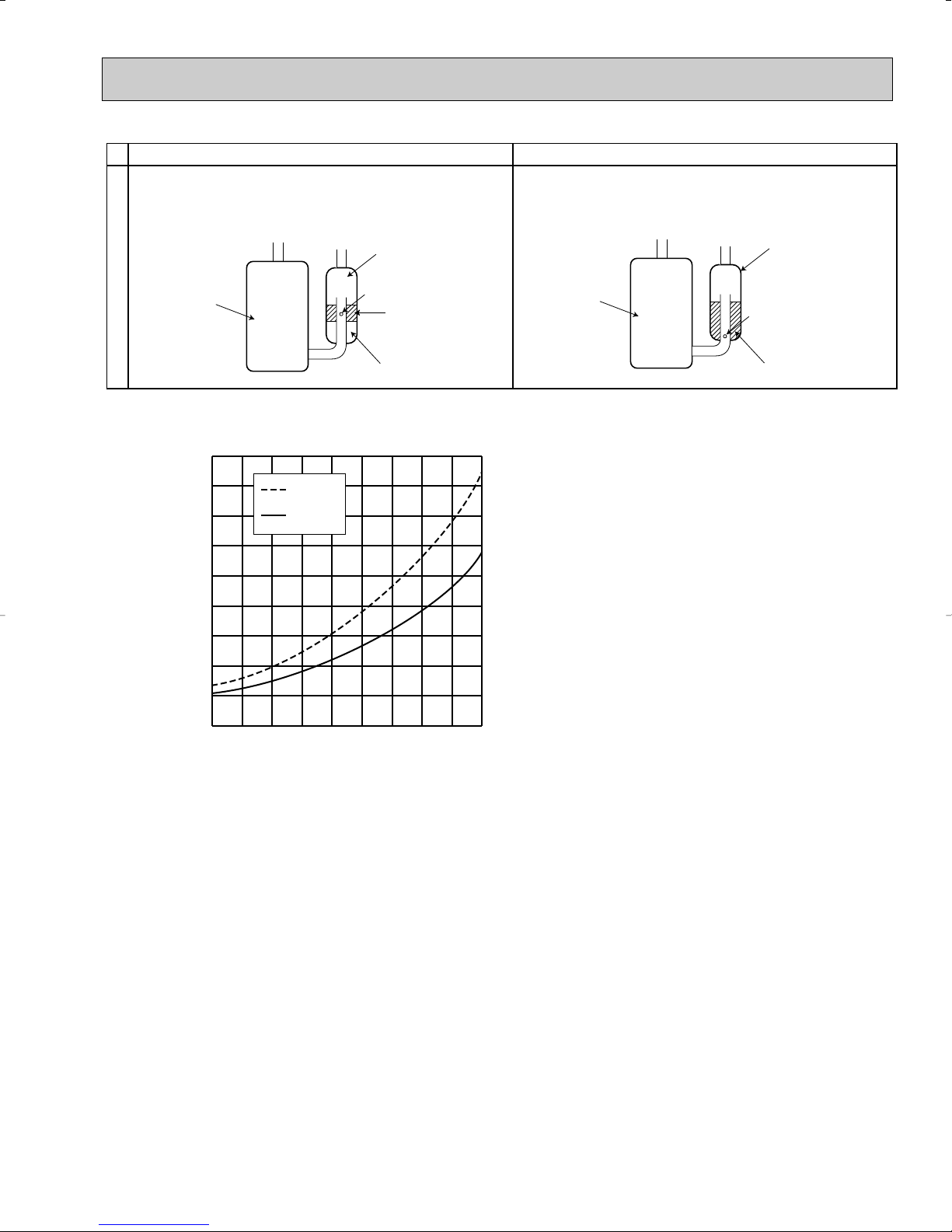
New Specification Current Specification
The incompatible refrigeration oil easily separates from
refrigerant and is in the upper layer inside the suction muffler.
Raising position of the oil back hole enables to back the
refrigeration oil of the upper layer to flow back to the
compressor.
Suction muffler
Since refrigerant and refrigeration oil are compatible each,
refrigeration oil goes back to the compressor through the
lower position oil back hole.
Suction muffler
Compressor
Compressor
Oil back hole
refrigeration oil
Refrigerant
Conversion chart of refrigerant temperature and pressure
580
508
435
363
290
(PSIG)
218
145
73
Saturated liquid pressure
0
-73
-22 -4 14 32 50 68
R410A
R22
104 122 140
86
Compressor
Oil back hole
refrigeration oil /Refrigerant
(°F)
3
R410A tools Can R22 tools be used?
Gas leak detector
R410A has high pressures beyond the measurement range of existing
gauges.
Hose material have been changed to improve the pressure resistance.
Dedicated for HFC refrigerant.
1/4in. and 3/8in.
Description
Clamp bar hole has been enlarged to reinforce the spring strength in the tool.
Provided for flaring work (to be used with R22 flare tool).
Provided to prevent the back flow of oil. This adapter enables you to use
vacuum pumps.
It is difficult to measure R410A with a charging cylinder because the
refrigerant bubbles due to high pressure and high-speed vaporization
No
No
No
Yes
Yes
New
New
New
Gauge manifold
Charge hose
Torque wrench
Flare tool
Flare gauge
Vacuum pump
adapter
Electronic scale for
refrigerant charging
No : Not Substitutable for R410A Yes : Substitutable for R410A
No 1/2in. and 5/8in.
1.Tools dedicated for the air conditioner with R410A refrigerant
R410A
Pipe diameter
inch
1/4
3/8
1/2
5/8
17 (11/16)
22 (7/8)
26 (1-1/32)
29 (1-5/32)
Dimension of flare nut
R22
mm(in.)
17 (11/16)
22 (7/8)
24 (15/16)
27 (1-1/16)
Wall thickness (in)
Outside diameter(in)
1/4
3/8
1/2
5/8
0.0315
0.0315
0.0315
0.0394
Heat resisting foam plastic
Specific gravity 0.045 Thickness 0.315 in
Insulation material
The following tools are required for R410A refrigerant. Some R22 tools can be substituted for R410A tools.
2.Refrigerant piping
1 Specifications
Use the copper or copper-alloy seamless pipes for refrigerant that meet the following specifications.
2 Flaring work and flare nut
Flaring work for R410A pipe differs from that for R22 pipe.
For details of flaring work, refer to Installation manual “FLARING WORK”.
4
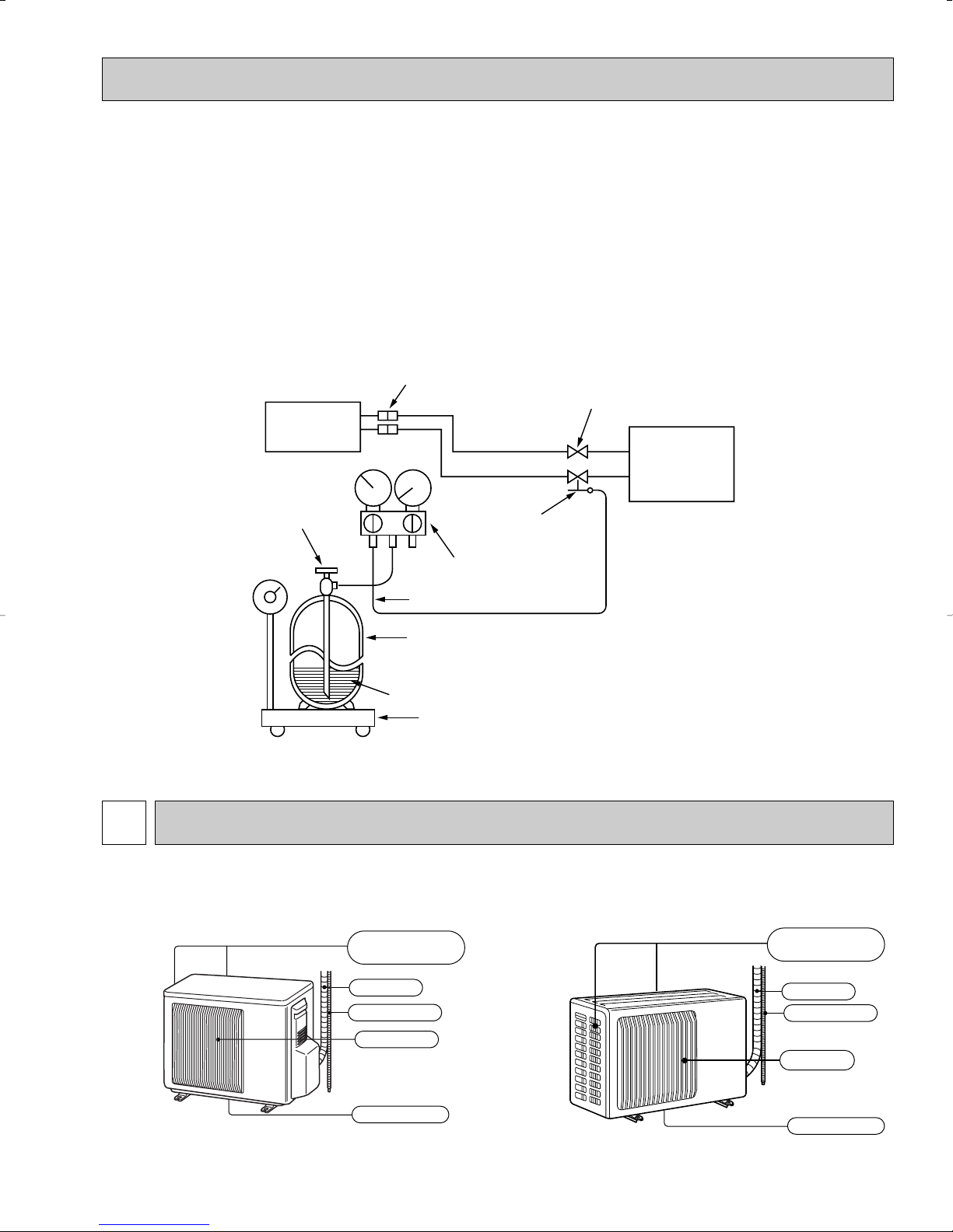
Air inlet
(back and side)
Air outlet
Drain outlet
Piping
Drain hose
Air inlet
Air outlet
(back and side)
Drain outlet
Piping
Drain hose
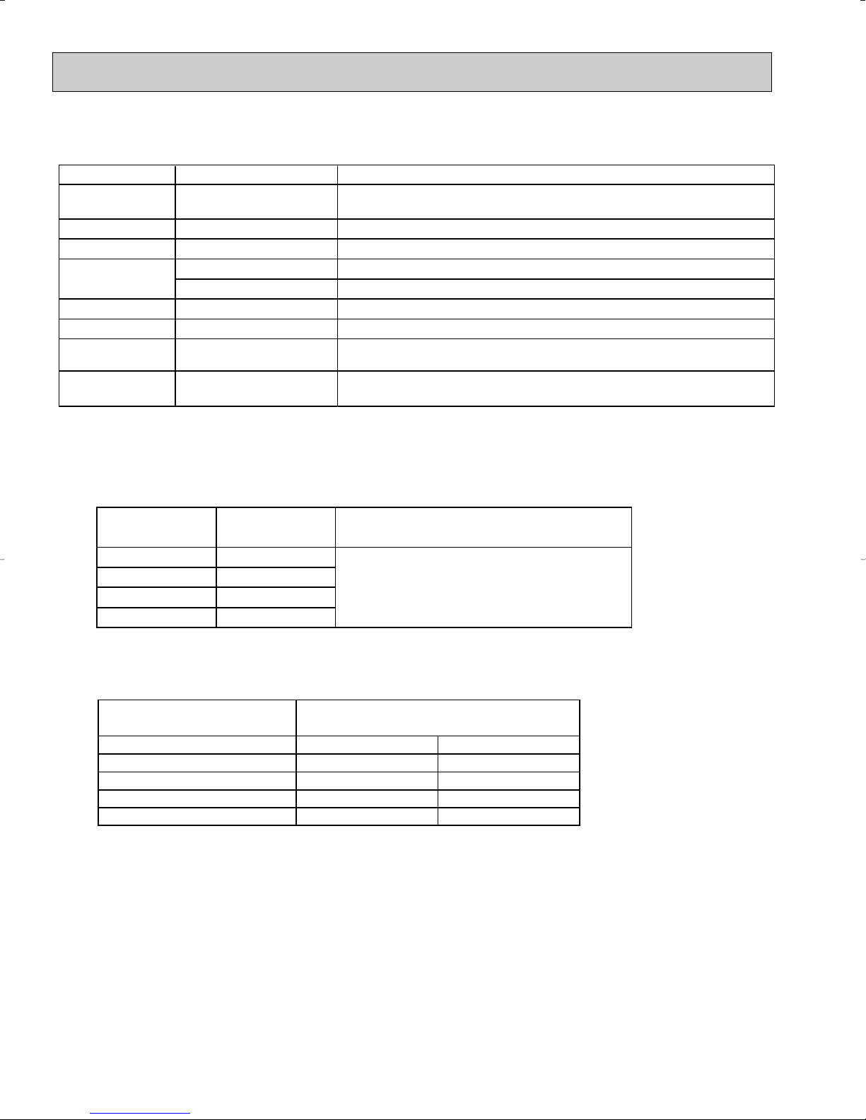
Electronic scale for refrigerant charging
Outdoor unit
Refrigerant gas
cylinder
operating valve
Refrigerant gas cylinder
for R410A with siphon
Refrigerant (liquid)
Service port
Gauge manifold
valve (for R410A)
Union
Liquid pipe
Gas pipe
Stop valve
Indoor unit
Charge hose (for R410A)
3.Refrigerant oil
Apply the special refrigeration oil (accessories: packed with indoor unit) to the flare and the union seat surfaces.
4.Air purge
• Do not discharge the refrigerant into the atmosphere.
Take care not to discharge refrigerant into the atmosphere during installation, reinstallation, or repairs to the refrigerant
circuit.
• Use the vacuum pump for air purging for the purpose of environmental protection.
5.Additional charge
For additional charging, charge the refrigerant from liquid phase of the gas cylinder.
If the refrigerant is charged from the gas phase, composition change may occur in the refrigerant inside the cylinder and the
outdoor unit. In this case, ability of the refrigeration cycle decreases or normal operation can be impossible. However,
charging the liquid refrigerant all at once may cause the compressor to be locked. Thus, charge the refrigerant slowly.
2
PART NAMES AND FUNCTIONS
MU-A09WA
5
MU-A12WA
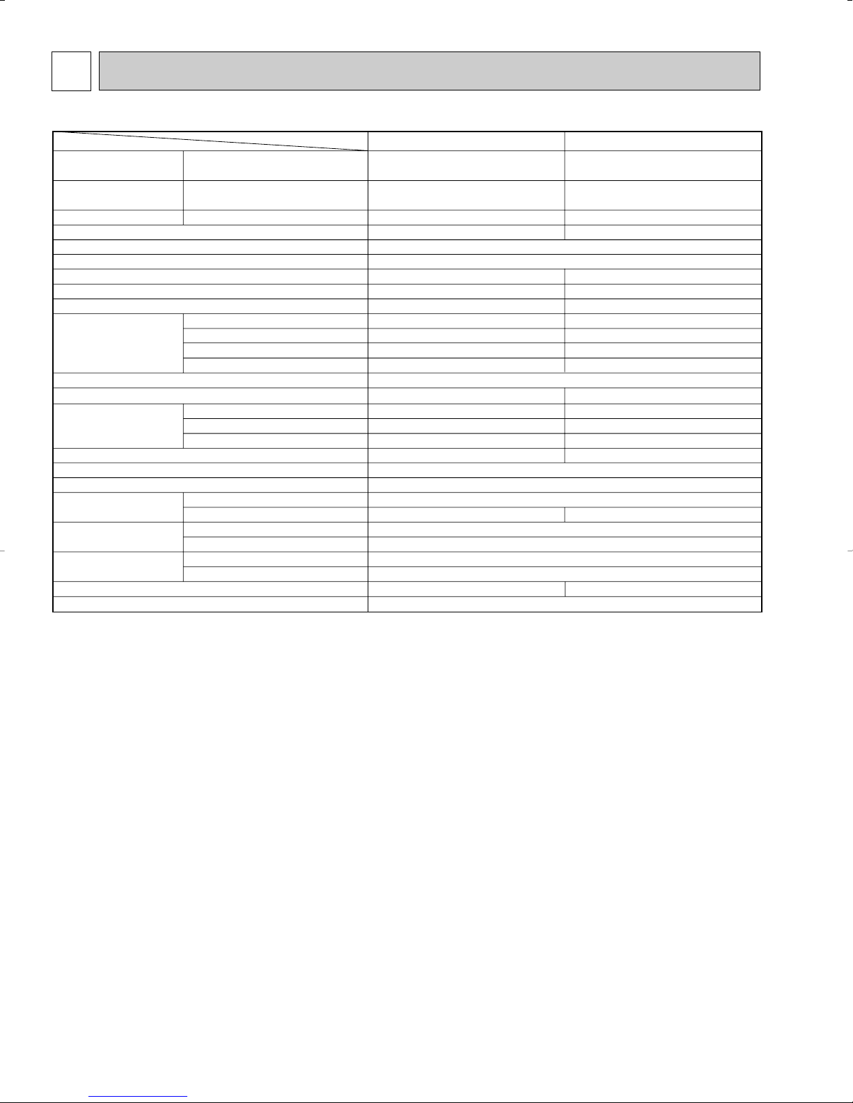
3
Item
Model
MS-A12WA
Capacity
Rated(Minimum~Maximum)
Power consumption
Rated(Minimum~Maximum)
EER [SEER]
OUTDOOR UNIT MODEL
External finish
Power supply
Max. fuse size (time delay)
Min. circuit ampacity
Fan motor
Compressor
Refrigerant control
Sound level
Dimensions
Weight
REMOTE CONTROLLER
REFRIGERANT PIPING
Refrigerant pipe size
(Min. wall thickness)
Connection method
Between the indoor
& outdoor units
Refrigerant charge (R410A)
Refrigerating oil (Model)
Btu/h
W
V, phase, Hz
A
A
F.L.A
R.L.A
L.R.A
dB(A)
in.
in.
in.
Ib.
in.
in.
ft.
ft.
cc
Munsell 3Y 7.8/1.1
115, 1, 60
Capillary tube
Wireless type
Not supplied
1/4 (0.0315)
Flared
Flared
35
65
350 (NE022)
12,000
1,070
11.2 [13.0]
MU-A12WA
20
16
0.926
RN110WHDHT
C-R 0.66 C-S 1.23
10.82
56
52
33-7/16
11-7/16
23-13/16
96
1/2 (0.0315)
3lb. 1oz.
9,500
870
10.9 [13.0]
MU-A09WA
15
14
0.63
RN092WHDHT
C-R 0.81 C-S 1.49
9.30
47
47
31-1/2
11-1/4
21-5/8
78
3/8 (0.0315)
2lb.5oz.
❈1 ❈2
❈1
❈1
Cooling
Cooling
Cooling
MS-A09WA
Model
Winding resistance (at 68˚F) Ω
W
D
H
Liquid
Gas
Indoor
Outdoor
Height difference
Piping length
SPECIFICATION
NOTE : Test conditions are based on ARI 210/240.
❈1 : Rating conditions (cooling) — Indoor : 80˚FDB, 67˚FWB, Outdoor : 95˚FDB, (75˚FWB)
6
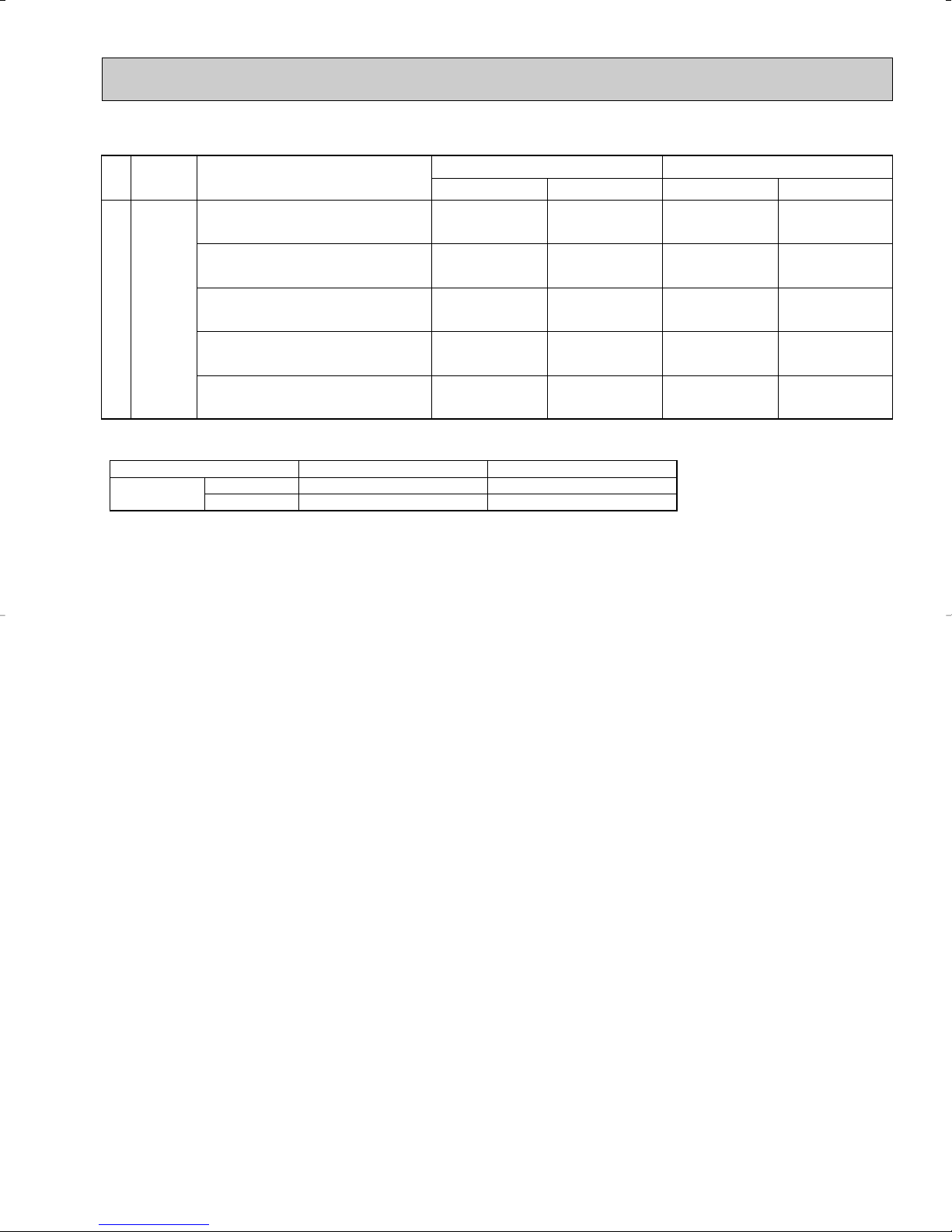
Operating Range
Cooling
Maximum
Minimum
Indoor intake air temperature
95˚FDB, 71˚FWB
67˚FDB, 57˚FWB
Outdoor intake air temperature
115˚FDB
67˚FDB
SEER
(Cooling)
ARI
Mode
"A" Cooling Steady State
at rated compressor Speed
"B-2" Cooling Steady State
at rated compressor Speed
"B-1" Cooling Steady State
at minimum compressor Speed
Low ambient Cooling Steady State
at minimum compressor Speed
Intermediate Cooling Steady State
At Intermediate compressor Speed
Test
Indoor air condition Outdoor air condition
Dry bulb
Wet bulb
Dry bulb
Wet bulb
80
80
80
80
80
67
67
67
67
67
95
82
82
67
87
(75)
(65)
(65)
(53.5)
(69)
(Unit : [˚F])
❈2
7

4
13-31/32
13-3/4
13/16
1-15/16
13-9/16
12-3/16
11-7/16
Drainage
hole [5/8
Drainage
3holes [1-5/16
9-3/4
3-17/32
1-3/8
Air in
Air out
Air in
23-13/16
11-1/2
13/16
19-11/16
7-3/16
3-3/16
2-1/4
33-7/16
6-3/16
3-15/16
1-3/16
6-5/16
30
35
Service panel
Liquid refrigerant
pipe joint
Refrigerant pipe
(flared) [1/4
Gas refrigerant
pipe joint
Rfrigerant pipe
(flared) [1/2
REQUIRED SPACE
4 in. or more
4 in. or more
4 in. or more
14 in. or more
20 in. or more
Liquid pipe : 1/4 (flared)
Gas pipe
: 3/8 (flared)
6-23/32
2
5-7/8
2-23/32
1-3/4
15-3/4
12 ~ 12-3/4
13-9/16
11/16
1-9/16
7/8
21-5/8
11-1/32
13/32
31-1/2
19-11/16
5-15/16
11-29/32
17/3229/32 11-1/4
Air in
handle
Air in
Air out
2- 3/8o13/16 Oval hole
Drainage hole 1-5/8
REQUIRED SPACE
Basically open 4inch or more
without any obstruction in front
and on both sides of the unit.
14 in. or more
8 in. or more
4 in. or more
4 in. or more
Open two sides of left,
right, or rear side.
OUTLINES AND DIMENSIONS
MU-A09WA
Unit : inch
MU-A12WA
8
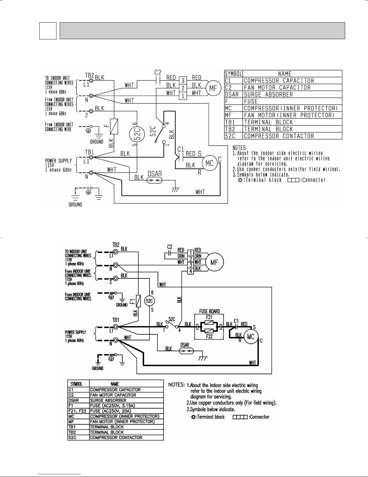
WIRING DIAGRAM5
MU-A09WA
MU-A12WA
9
 Loading...