

Page 1
SPLIT-TYPE, AIR CONDITIONERS
Revision:
●MS-09SN -, MS-10SN -, MS-12SN -, MS-15SN -
and MS-18SN - has been added.
●Please void OB256 REVISED EDITION-A.
SERVICE MANUAL
Wireless type
Models
C2C2C2C2
C1
No. OB256
REVISED EDITION-B
MS-09SN MS-09SN MS-10SN MS-10SN MS-12SN MS-12SN MS-15SN MS-15SN MS-17SN MS-18SN MS-24SN -
MS-09SN MS-09SN MS-10SN MS-10SN -
C1
C2
C1
C2
(WH)
(WH)
(WH)
(WH)
(WH)
(WH)
(WH)
(WH)
(WH)
(WH)
(WH)
· MU-09SN -
· MU-09SN -
· MU-10SN -
· MU-10SN -
· MU-12SN -
· MU-12SN -
· MU-15SN -
· MU-15SN -
· MU-17SN -
· MU-18SN -
· MU-24SN -
CONTENTS
1. TECHNICAL CHANGES ····································2
2. PART NAMES AND FUNCTIONS······················4
3. SPECIFICATION·················································6
4. OUTLINES AND DIMENSIONS·························9
5. WIRING DIAGRAM ··········································12
6. REFRIGERANT SYSTEM DIAGRAM··············18
7. PERFORMANCE CURVES······························22
8. MICROPROCESSOR CONTROL ····················25
9. SERVICE FUNCTIONS ····································32
10. TROUBLESHOOTING······································34
11. DISASSEMBLY INSTRUCTIONS ·····················42
12. PARTS LIST······················································50
13. OPTIONAL PARTS ···········································58
C1C1
C2C2
C1C1
C2C2
C1C1
C2C2
C1C1
C2C2
C1C1
C1C1
C1C1
Page 2
1
TECHNICAL CHANGES
MS-09NW - ➔ MS-09SN -
1. Power supply voltage has changed. (110V ➔ 220V)
2. Indoor unit model has changed.
3. Remote controller has changed.
• SLEEP MODE function has been removed.
• ECONO COOL operation has been added.
• SWING button was removed, but SWING MODE function is available by VANE CONTROLbutton.
MS-10SN -
New model
C1
MS-12NN - ➔ MS-12SN -
1. Design of receiver part on indoor unit has changed.
2. Remote controller has changed.
• SLEEP MODE function has been changed.
• ECONO COOL operation has been added.
• SWING button was removed, but SWING MODE function is available by VANE CONTROLbutton.
MS-15NN - ➔ MS-15SN MS-17NN - ➔ MS-17SN -
1. Design of receiver part on indoor unit has changed.
2. Remote controller has changed.
• SLEEP MODE function has been removed.
• ECONO COOL operation has been added.
• SWING button was removed, but SWING MODE function is available by VANE CONTROLbutton.
MS-24NN - ➔ MS-24SN -
1. Design of receiver part on indoor unit has changed.
2. Remote controller has changed.
• SLEEP MODE function has removed.
• ECONO COOL operation has added.
• SWING button was removed, but SWING MODE function is available by VANE CONTROLbutton.
C1C1
C1C1
C1C1
C1C1
C1C1
MS-09SN - ➔ MS-09SN MS-10SN - ➔ MS-10SN MS-12SN - ➔ MS-12SN MS-15SN - ➔ MS-15SN -
1. Fan guard has added.
2. Indoor electronic control P.C. board has changed.
Indoor fan speed has changed.
MS-18SN -
New model
C1
C2C1
C2C1
C2C1
C2C1
2
Page 3
MU-09NW - ➔ MU-09SN -
C1C1
1. Outdoor unit model has changed.
2. Additional refrigerant amount of extended pipe length over 7m has changed. (10g/m ➔ 15g/m)
MU-10SN -
C1
New model
MU-12NN - ➔ MU-12SN -
C1C1
1. Outdoor unit model has changed.
2. Additional refrigerant amount of extended pipe length over 7m has changed. (10g/m ➔ 15g/m)
3. Diameter of expansion pipe (GAS) has changed. ([15.88 ➔ [12.7)
MU-15NN - ➔ MU-15SN MU-17NN - ➔ MU-17SN -
C1C1
C1C1
1. Additional refrigerant amount of extended pipe length over 7m has changed. (10g/m ➔ 15g/m)
2. Service port has removed from outdoor unit.
3. Fusible plug has removed from outdoor unit.
MU-24NN - ➔ MU-24SN -
C1C1
1. Additional refrigerant amount of extended pipe length over 7m has changed. (10g/m ➔ 15g/m)
MU-09SN - ➔ MU-09SN MU-10SN - ➔ MU-10SN MU-12SN - ➔ MU-12SN MU-15SN - ➔ MU-15SN -
C2C1
C2C1
C2C1
C2C1
1. Sub number has changed.
MU-18SN -
C1
New model
3
Page 4
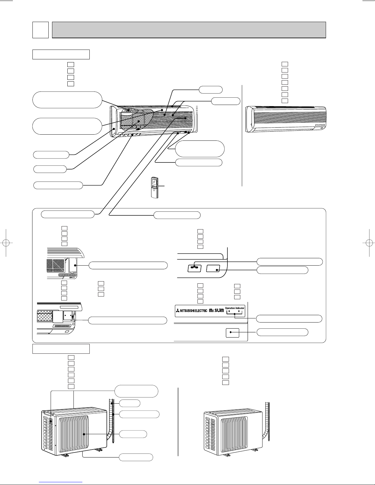
2
Emergency operation switch
Operation section
Horizontal vane
Air filter
Deodorizing filter(option)
(gray sponge type)
Vertical vane
Air inlet
Grille
Remote control
receiving section
Remote controller
Display section
(when the grille is open)
Operation indicator lamp
Receiving section
Air cleaning filter(option)
(white bellows type)
Front panel
Emergency operation switch
Operation indicator lamp
Receiving section
Air inlet
Piping
Drain hose
Air outlet
Drain outlet
(back and side)
PART NAMES AND FUNCTIONS
INDOOR UNIT
MS-09SN MS-09SN MS-10SN MS-10SN -
C1
C2
C1
C2
MS-12SN MS-12SN MS-15SN MS-15SN MS-17SN MS-18SN MS-24SN -
C1
C2
C1
C2
C1
C1
C1
MS-09SN MS-09SN MS-10SN MS-10SN -
C1
C2
C1
C2
MS-12SN MS-12SN MS-15SN MS-15SN -
C1
C2
C1
C2
OUTDOOR UNIT
MU-09SN MU-09SN MU-10SN MU-10SN MU-12SN MU-12SN -
MS-17SN MS-18SN MS-24SN -
C1
C2
C1
C2
C1
C2
MS-09SN MS-09SN MS-10SN MS-10SN -
C1
C2
C1
C2
C1
C1
C1
MS-12SN MS-12SN MS-15SN MS-15SN -
C1
MS-17SN -
C2
MS-18SN -
C1
MS-24SN -
C2
C1
C1
C1
MU-15SN MU-15SN MU-17SN MU-18SN MU-24SN -
C1
C2
C1
C1
C1
4
Page 5
ACCESSORIES
<Indoor unit>
Installation plate
Installation plate fixing screw 4 x 25 mm
Remote controller mounting hardware
Fixing screw for 3 3.5 x 16 mm (Black)
Battery (AAA) for remote controller
Wireless remote controller
Felt tape (Used for left or left-rear piping)
1
5
1
2
2
1
1
1
2
3
4
5
6
7
MS-09SNMS-09SN-
MS-12SNMS-12SNMS-15SNMS-15SN-
1
6
1
2
2
1
1
MS-17SNMS-18SNMS-24SN-
C2
C1
C2
C1
C2
C1
C1
C1
C1
REMOTE CONTROLLER
MS-09SN MS-09SN MS-10SN MS-10SN MS-12SN MS-12SN MS-15SN MS-15SN MS-17SN MS-18SN MS-24SN -
C1
C2
C1
C2
C1
C2
C1
C2
C1
C1
C1
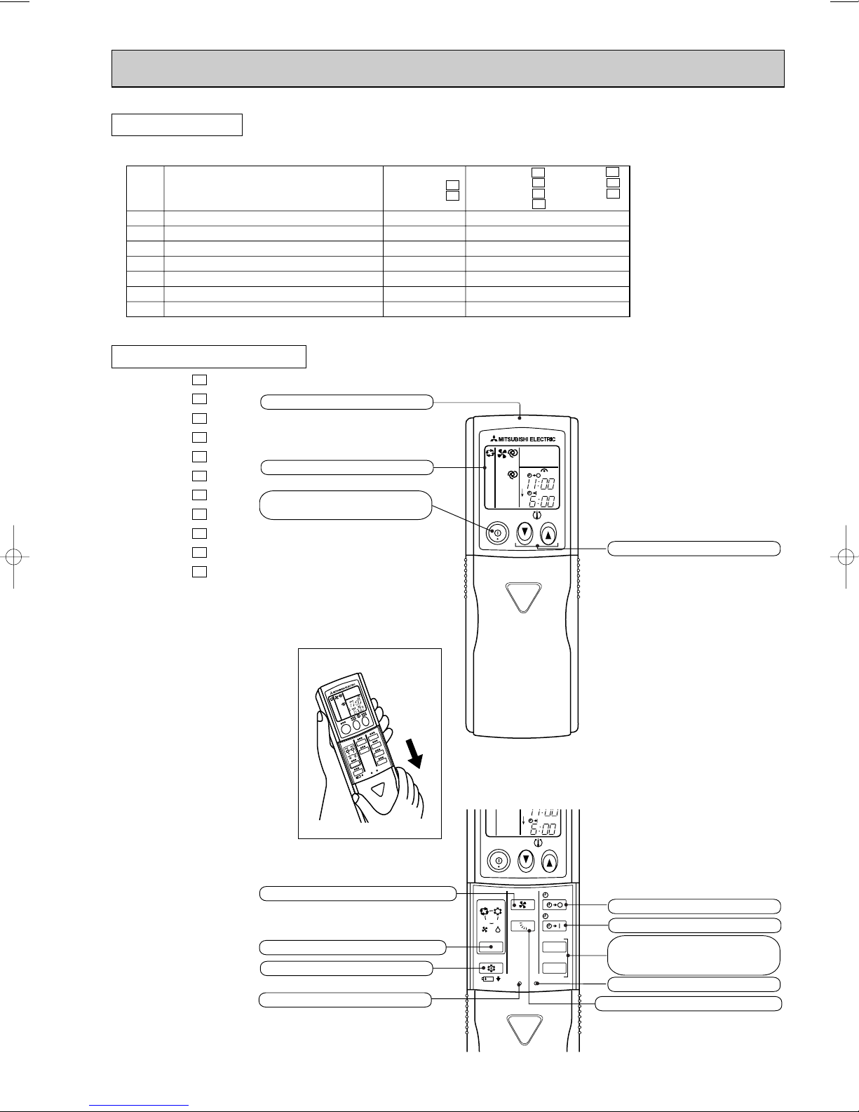
Signal transmitting section
Operation display section
OPERATE /STOP
(ON /OFF)button
ON/OFF
TOO
WARM
PM
AM
TOO
COOL
TEMPERATURE buttons
FAN SPEED CONTROL button
OPERATION SELECT button
Open the front lid.
ECONO COOL button
RESET button
5
ON/OFF
WARM
FAN
I FEEL
COOL
VANE
DRY
FAN
MODE
ECONO COOL
RESET
TOO
CLOCK
CLOCK
PM
AM
TOO
COOL
STOP
START
HR.
MIN.
OFF-TIMER button
ON-TIMER button
HR. button
MIN. button
(TIME SET button)
CLOCK SET button
VANE CONTROL button
Page 6
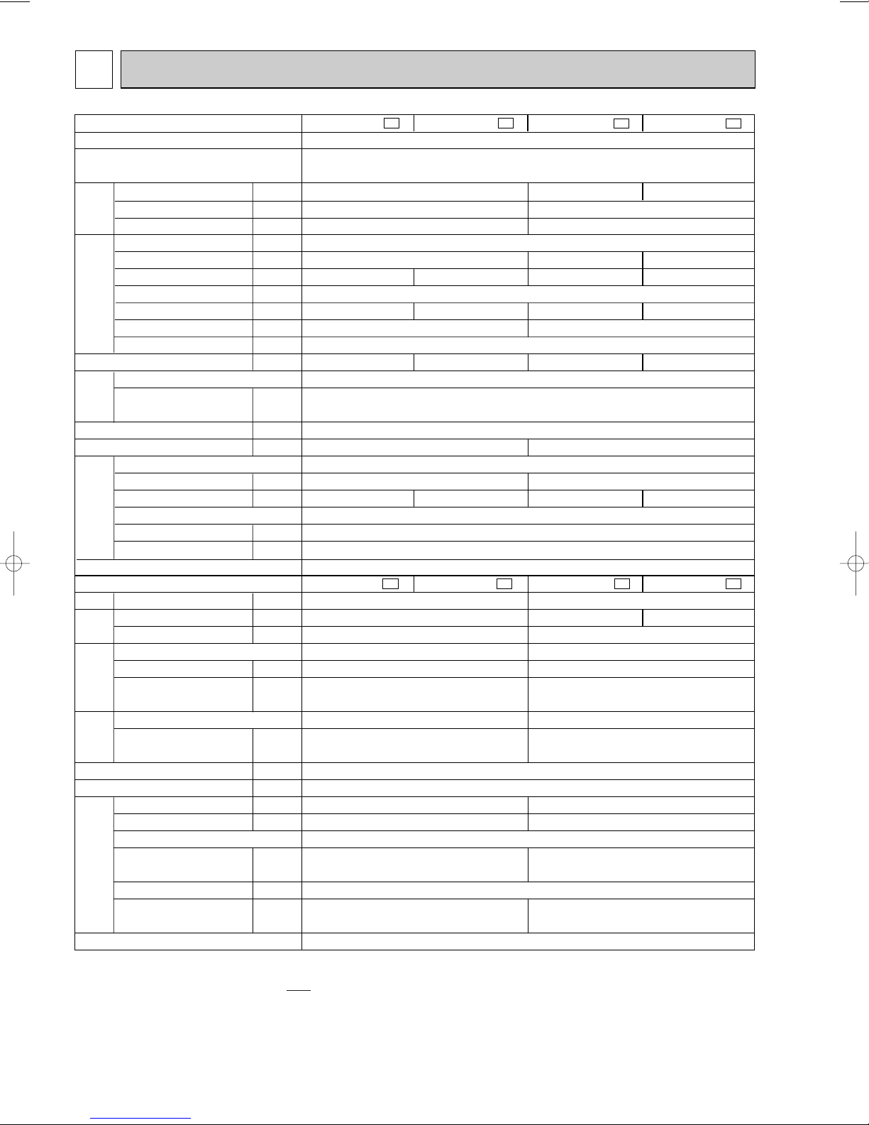
3
Indoor model
Function
Power supply
Capacity
Dehumidification
Air flow
(High/Med.w/Loww)
Power outlet
Running current
Total input
Auxiliary heater
Power factor
Starting current
Fan motor current
Model
Winding
resistance(at20:)
Dimensions WOHOD
Weight
Air direction
Sound level
(High/Med.w/Loww)
Fan speed
(High/Med.w/Loww)
Fan speed regulator
Thermistor RT11(at25:)
Thermistor RT12(at25:)
Outdoor model
Air flow
Compressor motor current
Fan motor current
Model
Output
Winding
resistance(at20:)
Model
Winding
resistance(at20:)
Dimensions WOHOD
Weight
Sound level
Fan speed
Fan speed regulator
Refrigerant filling
capacity(R22)
Refrigerating oil (Model)
Capillary tube
(Inner diameter O length)
(kcal/h)/(kW)
R/h
K /h
A
A
W
A(kW)
%
A
A
(kcal/h/W)/(W/W)
"
mm
kg
dB
rpm
k"
k"
K /h
A
A
W
"
"
mm
kg
dB
rpm
kg
cc
mm
MS-10SN -
C1
2,450/2.85
4.50
1,005
99
2.44/2.84
910/800w/680
w
MU-10SN -
C1
3.97
1.2
564/474
w
/384
w
26
10
37/33
w
/29
w
1,950
0.36
RH-145NGDT
700
C-R 2.74
C-S 3.78
RA6N33-AA
WHT-BLK 150
BLK-RED 265
49
740
0.82
[1.6 O 900
MS-10SN -
C2
2,500/2.91
4.61
992
98
2.52/2.93
940/830w/710
w
MU-10SN -
C2
4.08
Electrical
data
Fan
motor
Special
remarks
Compressor
Electrical
data
Fan
motor
Special
remarks
Capacity
Energy efficiency ratio (EER)
Capacity
Connection method
Connection method
MS-09SN -
C1
880
97
2.44/2.84
890/740w/600
w
MU-09SN -
C1
2,150/2.50
1.1
474/384
w
/300
w
4.13
21
9
35/30
w
/26
w
1,638
3.68
0.28
RH-130NGDT
650
C-R 3.19
C-S 3.55
RA6N23-AA
WHT-BLK 169
BLK-RED 226
45
630
0.80
[1.4 O 600
MS-09SN -
C2
843
93
2.55/2.97
920/770w/630
w
MU-09SN -
C2
Cooling
Single phase
220V, 60Hz
10
—
0.17
RC4N19-AA
WHT-BLK 335
BLK-RED 320
850O278O191
5
3
10
10
Flared
780o540o255
32
1
300(MS56)
Flared
SPECIFICATION
NOTE:Test conditions are based on CNS3615.
Cooling : Indoor DB 27°C / WB 19.5°C
Outdoor DB 35°C /
Indoor-Outdoor piping length 5m
w Reference value
6
Page 7
C1
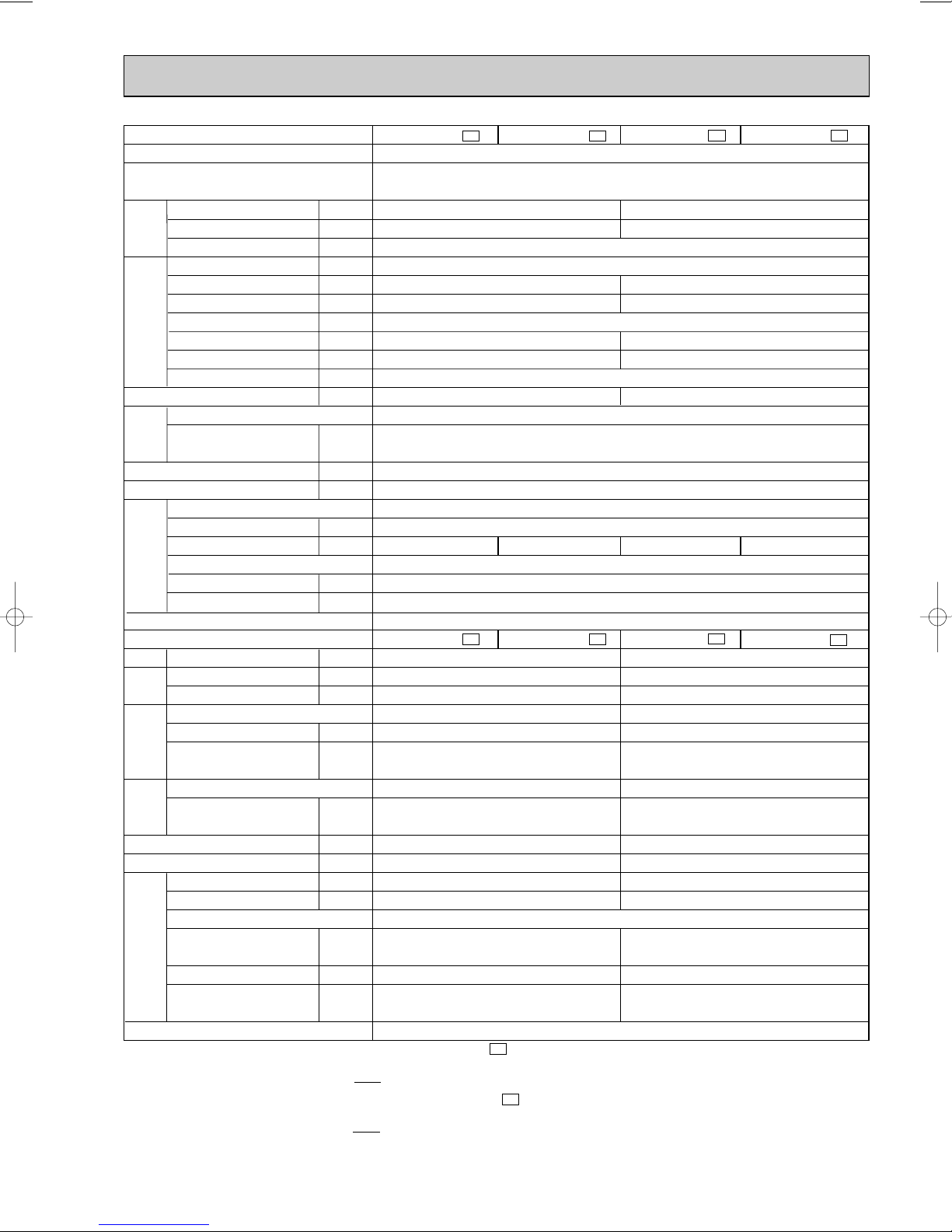
Indoor model
MS-12SN -
Function
Power supply
Capacity
Dehumidification
Capacity
Air flow
(High/Med.w/Loww)
Power outlet
Running current
Total input
Auxiliary heater
Electrical
data
Power factor
Starting current
Fan motor current
Energy efficiency ratio (EER)
(kcal/h)/(kW)
R/h
K /h
A
A
W
A(kW)
%
A
A
(kcal/h/W)(W/W)
3,150/3.66
1.5
5.14
1,120
99
30
2.81/3.27
Model
Winding
Fan
motor
resistance(at20:)
Dimensions WOHOD
Weight
"
mm
kg
Air direction
Sound level
Fan speed
Fan speed regulator
Special
remarks
Thermistor RT11(at25:)
Thermistor RT12(at25:)
(High/Med.w/Loww)
(High/Med.w/Loww)
dB
rpm
1,180/1,040w/900
w
k"
k"
Connection method
C1
Outdoor model
Capacity
Air flow
Compressor motor current
Fan motor current
Electrical
data
Model
Output
Winding
Compressor
resistance(at20:)
Model
Winding
Fan
motor
resistance(at20:)
Dimensions WOHOD
Weight
Sound level
Fan speed
MU-12SN -
K /h
A
A
W
"
"
mm
kg
dB
rpm
1,656
4.52
0.36
RH-167NHDT
800
C-R 2.16
C-S 3.11
RA6N33-AA
WHT-BLK 150
BLK-RED 265
780o540o255
36
49
700
Fan speed regulator
Refrigerant filling
capacity(R22)
Special
remarks
Refrigerating oil (Model)
Capillary tube
(Inner diameter O length)
kg
cc
mm
1.20
520(MS56)
[1.8O 500
Connection method
NOTE:Test conditions are based on CNS3615. (MS-12/15SN- )
C1
Cooling : Indoor DB 27°C / WB 19.5°C
Outdoor DB 35°C /
Test conditions are based on CNS 14464. (MS-12/15SN- )
Cooling : Indoor DB 27°C / WB 19°C
Outdoor DB 35°C /
Indoor-Outdoor piping length 5m
w Reference value
7
MS-12SN -
Single phase
220V, 60Hz
780/672
RA4N30-AB
WHT-BLK 118
BLK-RED 162
1,015O320O190
42/38
1,210/1,070w/930
MU-12SN -
C2
C2
MS-15SN -
Cooling
w
/570
15
—
0.26
14
5
w
w
/34
w
1,180/1,040w/900
3
10
10
Flared
C2
MU-15SN -
1
Flared
w
C1
MS-15SN -
3,650/4.24
2.2
6.50
1,400
98
36
2.61/3.03
w
1,210/1,070w/930
C1
MU-15SN -
2,340
5.74
0.50
RH-207NHDT
1,000
C-R 1.68
C-S 2.78
RA6N50-BA
WHT-BLK 116
BLK-RED 111
850o605o290
42
52
865
1.30
520(MS56)
[1.8 O 550
C2
w
C2
Page 8
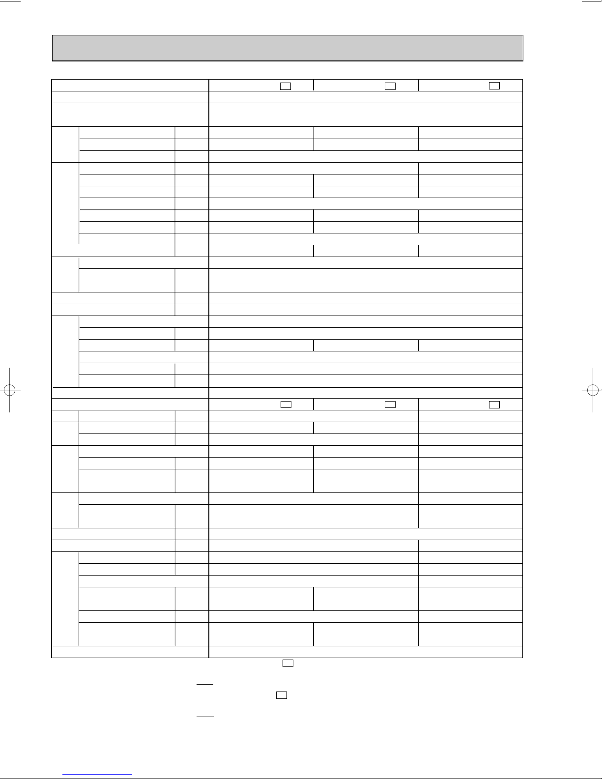
Indoor model
Function
Power supply
Capacity
Dehumidification
Air flow
(High/Med.w/Loww)
Power outlet
Running current
Total input
Auxiliary heater
Power factor
Starting current
Fan motor current
Model
Winding
resistance(at20:)
Dimensions WOHOD
Weight
Air direction
Sound level
(High/Med.w/Loww)
Fan speed
(High/Med.w/Loww)
Fan speed regulator
Thermistor RT11(at25:)
Thermistor RT12(at25:)
Outdoor model
Air flow
Compressor motor current
Fan motor current
Model
Output
Winding
resistance(at20:)
Model
Winding
resistance(at20:)
Dimensions WOHOD
Weight
Sound level
Fan speed (High)
Fan speed regulator
Refrigerant filling
capacity(R22)
Refrigerating oil (Model)
Capillary tube
(Inner diameter O length)
(kcal/h)/(kW)
R/h
K /h
A
A
W
A(kW)
%
A
A
(kcal/h/W)/(W/W)
"
mm
kg
dB
rpm
k"
k"
K /h
A
A
W
"
"
mm
kg
dB
rpm
kg
cc
mm
Electrical
data
Fan
motor
Special
remarks
Compressor
Electrical
data
Fan
motor
Special
remarks
Capacity
Energy efficiency ratio (EER)
Capacity
Connection method
Connection method
Cooling
Single phase
220V, 60Hz
—
0.29
RA4N30-AB
WHT-BLK 118
BLK-RED 162
1,015O320O190
14
5
3
10
10
Flared
850O605O290
Flared
MS-17SN -
C1
3,950/4.59
2.3
7.30
1,580
98
39
2.50/2.91
1,260/1,140
w
/1,020
w
MU-17SN -
C1
6.51
RH-231NHDT
1,100
C-R 1.65
C-S 2.67
1.35
[2.0 O 700
2,280
0.50
RA6N50-BA
WHT-BLK 116
BLK-RED 111
44
52
865
1
520(MS56)
15
MS-18SN -
C1
4,500/5.23
2.6
840/750
w
/660
w
8.77
1,910
99
49
2.36/2.74
45/41
w
/38
w
1,290/1,170w/1,050
w
MU-18SN -
C1
7.98
RH-277NHDT
1,300
C-R 1.38
C-S 2.55
1.40
[2.0 O 500
MS-24SN -
C1
5,600/6.51
3.4
20
14.00
3,040
99
56
1.84/2.14
1,260/1,140
w
/1,020
w
MU-24SN -
C1
2,460
13.08
0.63
NH-38NBDT
1,700
C-R 0.83
C-S 1.83
RA6V60-AC
WHT-BLK 81.1, BLK-RED 102
BLK-YLW 92.2
61
54
930
2
2.15
1,200(MS32)
[2.0O 700(600+100)
NOTE:Test conditions are based on CNS3615. (MS-17/24SN- )
Cooling : Indoor DB 27°C / WB 19.5°C
Outdoor DB 35°C /
Test conditions are based on CNS14464. (MS-18SN- )
Cooling : Indoor DB 27°C / WB 19°C
Outdoor DB 35°C /
Indoor-Outdoor piping length 5m
w Reference value
C1
C1
8
Page 9
4
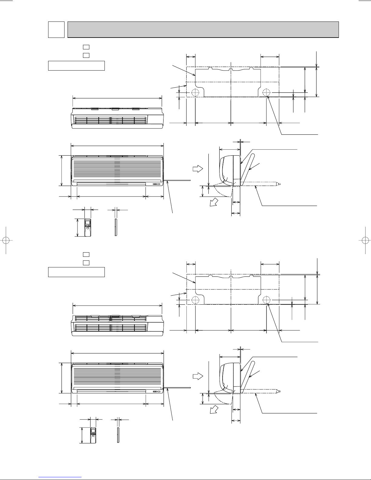
OUTLINES AND DIMENSIONS
MS-09SN MS-09SN -
INDOOR UNIT
278
58
162
231.5
42
Unit: mm
271 4.5
C1
169
2.5
116.581.5
Wall hole [65
Installation plate
Liquid line [ 6.35-0.5m
Gas line [
{
Insulation [37 O.D
Drain hose [16
(Connected part O.D)
Insulation [ 28
9.52-0.43m
[ 21 I.D
41
Air in
82
326
7 or more
100
Air out
326
5
189
67
78
C2
Installation plate
Indoor unit
818
850
16562956
19
Power supply cord
Lead to right 1.0m
Lead to left 0.3m
Wireless remote controller
MS-10SN MS-10SN -
INDOOR UNIT
278
58
162
C1
41
Air in
82
326 326
189
or more
7
100
Air out
78
5
67
C2
Installation plate
Indoor unit
818
850
16562956
19
Power supply cord
Lead to right 1.0m
Lead to left 0.3m
169
2.5
116.581.5
Wall hole [65
Installation plate
Liquid line [6.35-0.5m
Gas line [9.52-0.43m
{
Insulation [37 O.D
[21 I.D
Drain hose [16
(Connected part O.D)
Insulation [28
231.5
42
271 4.5
Wireless remote controller
9
Page 10
320
25
43-
35-
155
90
104
74
260
10
780
500
122
40
540
320
285
255
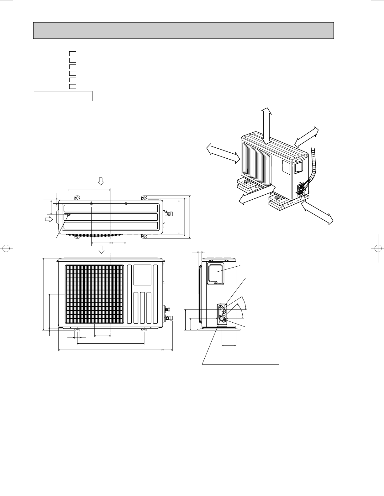
Service panel
Gas refrigerant
pipe joint
Refrigerant pipe
(flared) [9.52 (MU-09/10SN
)
[12.7 (MU-12SN
)
Liquid refrigerant
pipe joint
Refrigerant pipe
(flared) [6.35
Airout
Air in
Air in
Service port
109
32
110
147
Drainage
3holes [33
If clearance
behind the outdoor unit
is only 400
mm
or 500
mm
side A must be fully opened.
100mm or more
100mm or more
100mm or more
350mm or more
REQUIRED SPACE
A
400mm or more
MU-09SN MU-09SN MU-10SN MU-10SN MU-12SN MU-12SN -
C1
C2
C1
C2
C1
C2
OUTDOOR UNIT
Unit: mm
10
Page 11
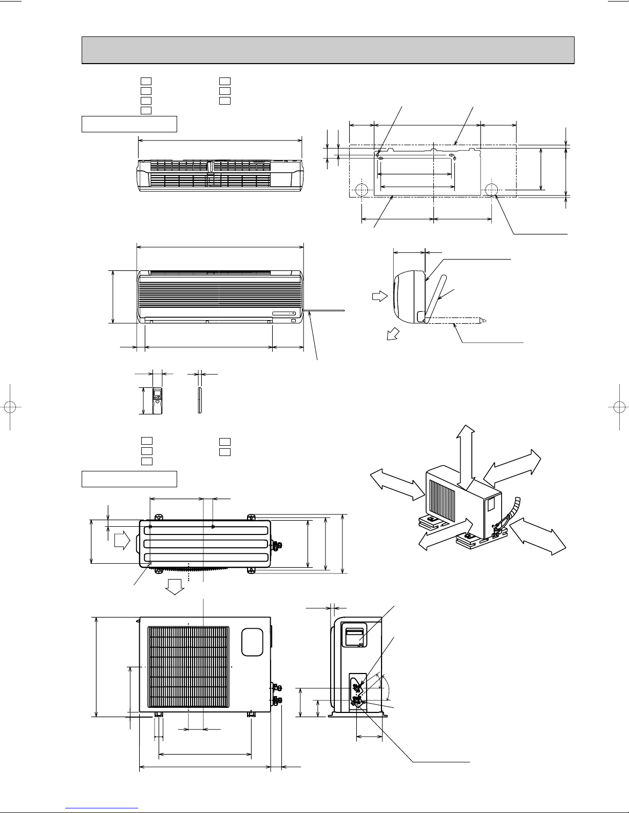
MS-12SN MS-12SN MS-15SN MS-15SN -
INDOOR UNIT
C1
MS-17SN -
C2
MS-18SN -
C1
MS-24SN -
C2
995
C1
C1
C1
60
40
4holes 11x 20
150 648 217
Indoor unit
20
320
58
162
Wireless remote controller
MU-15SN MU-15SN MU-17SN -
C1
MU-18SN -
C2
MU-24SN -
C1
OUTDOOR UNIT
35
248
Air in
350
1015
19
450
450
352438
Installation plate
5190
Installation plate
Liquid line
Gas line
Air in
19077550
Power supply cord
Lead to right 2m
Lead to left 1m
C1
C1
20
310
345
290
Air out
REQUIRED SPACE
100mm or more
If clearance
behind the
outdoor unit is
only 400
500
must be fully
opened.
mm,
or
mm
side A
{
Insulation
Drain hose
A
500mm or more
Insulation
100mm or more
[8-0.5m
[ 12-0.43m
[ 50 O.D
[ 28 I.D
100mm or more
254
Wall hole
[
16
[
28
350mm or more
3 297
[ 75
Drainage
3holes [16.2
Air out
605
292
20
183
50
500
850
74
157
30
100
11
161
Service panel
Liquid refrigerant
pipe joint
Refrigerant pipe (flared)
o
[6.35 (MU-15/17/18SN)
30
[9.52 (MU-24SN)
o
35
Gas refrigerant
pipe joint
Refrigerant pipe (flared)
[15.88
Service port
Page 12
5
SYMBOL
RT12
SR141
TB
52C
SYMBOL
MF
MV
NR11
RT11
SYMBOL
C11
F11
F12
HIC1
NAME
NAME NAME
INDOOR FAN CAPACITOR
FUSE(3.15A)
THERMAL FUSE(93:)
DC/DC CONVERTER
INDOOR FAN MOTOR(INNER FUSE)
VANE MOTOR
VARISTOR
ROOM TEMPERATURE THERMIST OR
INDOOR COIL THERMISTOR
SOLID STATE RELAY
TERMINAL BLOCK
CONTACTOR
3
2
2
3
RT12
RT11
BLK
GRY
YLW
BRN
WHT
RED
1
2
3
4
5
6
MF
F11
52C
HIC1
TRANS
NR11
C11
SR141
CN211
112
CN
CN
111
121
CN
1
3
ELECTRONIC CONTROL P.C. BOARD
TB
REMOTE
CONTROLLER
POWER MONITOR,
RECEIVER
P.C. BOARD
MV
F12
POWER
SUPPLY
CORD
1[ 220V~
60Hz
L1
L
2
1
1
2
4
3
CN201
CN
151
5
5
LD101T
GRN/YLW
BLU
WHT
BLU
BLU
BRN
BLU
BLU
BLU
C
220V~
TO OUTDOOR
UNIT
CONNECTING
BRN
GRN/YLW
FROM INDOOR
UNIT
CONNECTING
220V~
BLU
WHT
C
2
C2
TB
MF
RED
BLK
WHT
MC
C1
S
R
C
WHT
BLK
RED
SYMBOL
TB
SYMBOL
MC
MF
SYMBOL
C1
C2
NAME
NAME NAME
COMPRESSOR CAPACITOR
OUTDOOR FAN CAPACITOR
COMPRESSOR(INNER PROTECTOR)
OUTDOOR FAN MOTOR(INNER PROTECTOR)
TERMINAL BLOCK
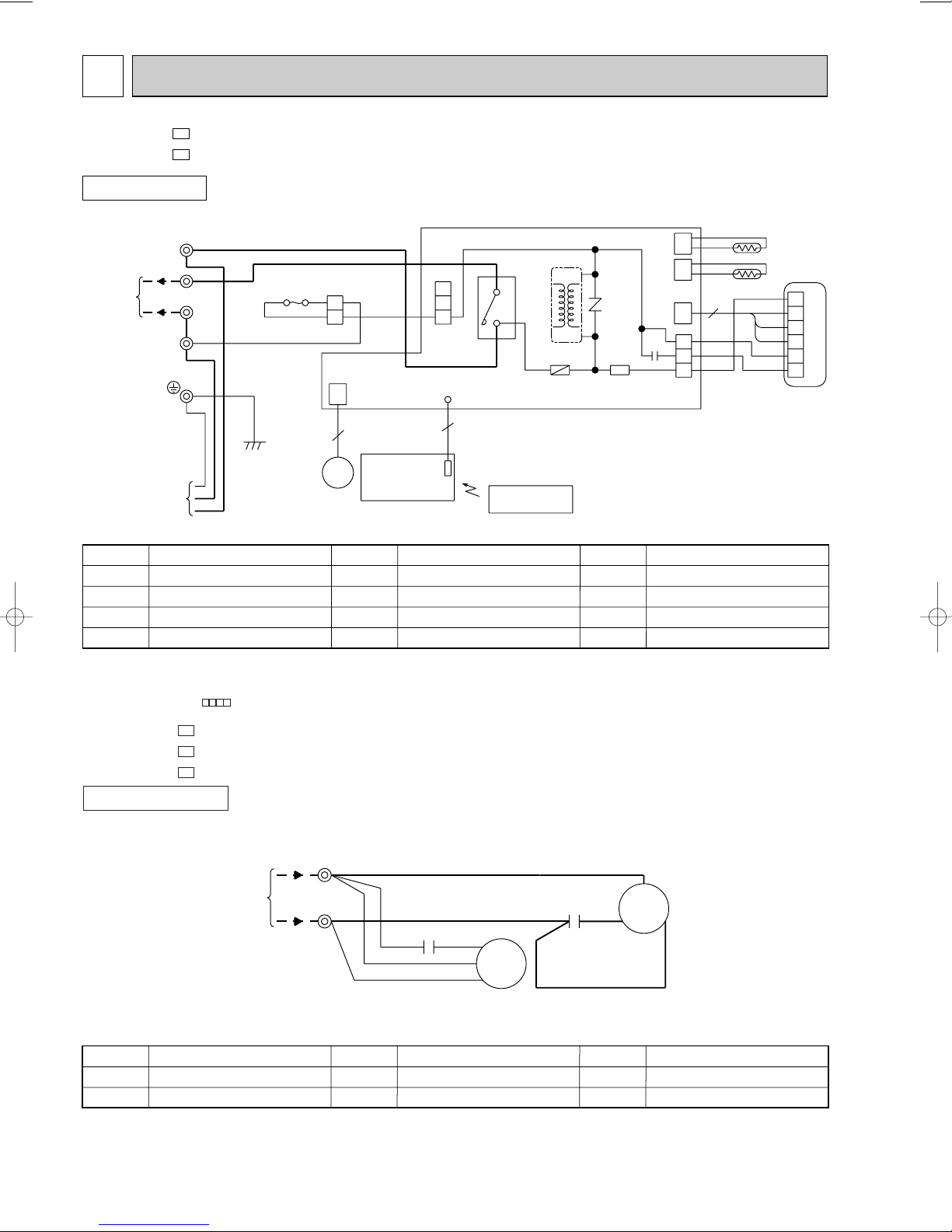
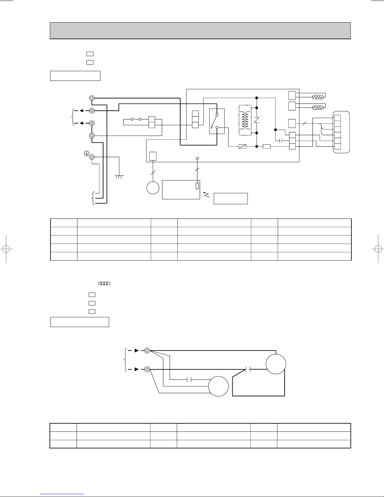
WIRING DIAGRAM
MS-09SN MS-10SN -
C1
C1
INDOOR UNIT
MODELS WIRING DIAGRAM
NOTE:1. About the outdoor side electric wiring refer to the outdoor unit electric wiring diagram for servicing.
2. Use copper conductors only. (For field wiring)
3. Symbols below indicate.
/: Terminal block, : Connector
C1
C1
C1
MODELS WIRING DIAGRAM
MU-09SN MU-10SN MU-12SN -
OUTDOOR UNIT
NOTE:1. About the indoor side electric wiring refer to the indoor unit electric wiring diagram for servicing.
2.Use copper conductors only. (For field wiring)
3. Symbols below indicate.
/: Terminal block
12
SG79B730H02
VG79B076H01
Page 13
MS-09SN -
SYMBOL
RT12
SR141
TB
52C
SYMBOL
MF
MV
NR11
RT11
SYMBOL
C11
F11
F12
HIC1
NAME
NAME NAME
INDOOR FAN CAPACITOR
FUSE(3.15A)
THERMAL FUSE(93:)
DC/DC CONVERTER
INDOOR FAN MOTOR(INNER FUSE)
VANE MOTOR
VARISTOR
ROOM TEMPERATURE THERMIST OR
INDOOR COIL THERMISTOR
SOLID STATE RELAY
TERMINAL BLOCK
CONTACTOR
3
2
2
3
RT12
RT11
BLK
GRY
YLW
BRN
WHT
RED
1
2
3
4
5
6
MF
F11
52C
HIC1
TRANS
NR11
C11
SR141
CN211
112
CN
CN
111
121
CN
1
3
ELECTRONIC CONTROL P.C. BOARD
TB
REMOTE
CONTROLLER
POWER MONITOR,
RECEIVER
P.C. BOARD
MV
F12
POWER
SUPPLY
CORD
1[ 220V~
60Hz
L1
L
2
1
1
2
4
3
CN201
CN
151
5
5
LD101T
GRN/YLW
BLU
WHT
BLU
BLU
BRN
BLU
BLU
BLU
C
220V~
TO OUTDOOR
UNIT
CONNECTING
BRN
GRN/YLW
FROM INDOOR
UNIT
CONNECTING
220V~
BLU
WHT
C
2
C2
TB
MF
RED
BLK
WHT
MC
C1
S
R
C
WHT
BLK
RED
SYMBOL
TB
SYMBOL
MC
MF
SYMBOL
C1
C2
NAME
NAME NAME
COMPRESSOR CAPACITOR
OUTDOOR FAN CAPACITOR
COMPRESSOR(INNER PROTECTOR)
OUTDOOR FAN MOTOR(INNER PROTECTOR)
TERMINAL BLOCK
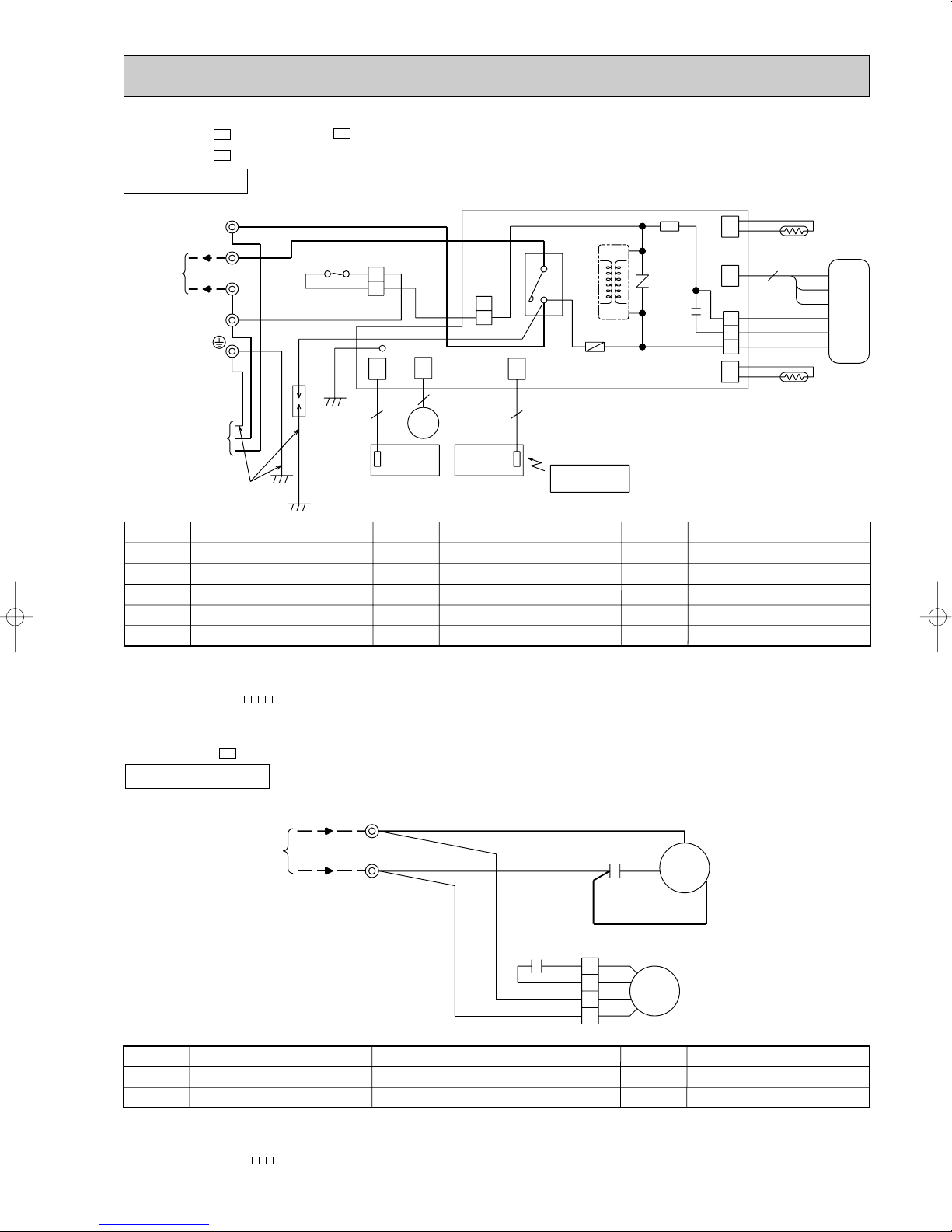
MS-10SN -
C2
C2
INDOOR UNIT
MODELS WIRING DIAGRAM
NOTE:1. About the outdoor side electric wiring refer to the outdoor unit electric wiring diagram for servicing.
2. Use copper conductors only. (For field wiring)
3. Symbols below indicate.
/: Terminal block, : Connector
C2
C2
C2
MODELS WIRING DIAGRAM
MU-09SN MU-10SN MU-12SN -
OUTDOOR UNIT
NOTE:1. About the indoor side electric wiring refer to the indoor unit electric wiring diagram for servicing.
2.Use copper conductors only. (For field wiring)
3. Symbols below indicate.
/: Terminal block
13
SG79J520H01
VG79B176H01
Page 14

MS-12SN -
SYMBOL
RT12
TB
52C
SYMBOL
IC141
MF
MV
NR11
RT11
SYMBOL
C11
DSAR
F11
F12
HIC1
NAME
NAME NAME
INDOOR FAN CAPACITOR
SURGE ABSORBER
FUSE(3.15A)
THERMAL FUSE(93:)
DC/DC CONVERTER
HYBRID IC
INDOOR FAN MOTOR(INNER FUSE)
VANE MOTOR
VARISTOR
ROOM TEMPERATURE THERMIST OR
INDOOR COIL THERMISTOR
TERMINAL BLOCK
CONTACTOR
220V~
BLU
BRN
2
60Hz
TRANS
HIC1
BRN
DSAR
GRN/YLW
LD1
REMOTE
CONTROLLER
3
1
DISPLAY
P.C.BOARD
101
CN
102
CN
151
CN
111
CN
ELECTRONIC CONTROL P.C. BOARD
4
2
1
C11
CN211
BLU
RECEIVER
P.C.BOARD
BLK
WHT
GRY
RED
RT11
MV
5
F11
33
BLU
MF
3
121
CN
CN
112
1[ 220V~
CORD
POWER
SUPPLY
TO OUTDOOR
UNIT
CONNECTING
BRN
L
L1
GRN/YLW
TB
NR11
IC141
52C
C
RT12
YLW
BRN
4
3
CN201
1
2
F12
WHT
BLU
BLU
BLU
MS-15SN -
C1
C1
INDOOR UNIT
MS-17SN -
MODELS WIRING DIAGRAM
C1
NOTE:1. About the outdoor side electric wiring refer to the outdoor unit electric wiring diagram for servicing.
2. Use copper conductors only. (For field wiring)
3. Symbols below indicate.
/: Terminal block, : Connector
MU-15SN MU-17SN -
OUTDOOR UNIT
C1
C1
MODELS WIRING DIAGRAM
FROM
INDOOR UNIT
CONNECTING
220V~
SYMBOL
C1
C2
NOTE:1. About the indoor side electric wiring refer to the indoor unit electric wiring diagram for servicing.
2.Use copper conductors only. (For field wiring)
3. Symbols below indicate.
/: Terminal block, : Connector
COMPRESSOR CAPACITOR
OUTDOOR FAN CAPACITOR
NAME
TB
2
C
SYMBOL
MC
MF
COMPRESSOR(INNER PROTECTOR)
OUTDOOR FAN MOTOR(INNER PROTECTOR)
NAME NAME
14
WHT
BLU
C2
RED
ORN
WHT
BLU
C
C1
RED
MC
S
R
BLK
RED
1
ORN
2
WHT
3
BLK
4
SYMBOL
TB
MF
TERMINAL BLOCK
Page 15
MS-12SN -
SYMBOL
RT12
TB
52C
SYMBOL
IC141
MF
MV
NR11
RT11
SYMBOL
C11
DSAR
F11
F12
HIC1
NAME
NAME NAME
INDOOR FAN CAPACITOR
SURGE ABSORBER
FUSE(3.15A)
THERMAL FUSE(93:)
DC/DC CONVERTER
HYBRID IC
INDOOR FAN MOTOR(INNER FUSE)
VANE MOTOR
VARISTOR
ROOM TEMPERATURE THERMIST OR
INDOOR COIL THERMISTOR
TERMINAL BLOCK
CONTACTOR
220V~
BLU
BRN
2
60Hz
TRANS
HIC1
BRN
DSAR
GRN/YLW
LD1
REMOTE
CONTROLLER
3
1
DISPLAY
P.C.BOARD
101
CN
102
CN
151
CN
111
CN
ELECTRONIC CONTROL P.C. BOARD
4
2
1
C11
CN211
BLU
RECEIVER
P.C.BOARD
BLK
WHT
GRY
RED
RT11
MV
5
F11
33
BLU
MF
3
121
CN
CN
112
1[ 220V~
CORD
POWER
SUPPLY
TO OUTDOOR
UNIT
CONNECTING
BRN
L
L1
GRN/YLW
TB
NR11
IC141
52C
C
RT12
YLW
BRN
4
3
CN201
1
2
F12
WHT
BLU
BLU
BLU
MS-15SN -
C2
C2
INDOOR UNIT
MS-18SN -
MODELS WIRING DIAGRAM
C1
NOTE:1. About the outdoor side electric wiring refer to the outdoor unit electric wiring diagram for servicing.
2. Use copper conductors only. (For field wiring)
3. Symbols below indicate.
/: Terminal block, : Connector
MU-15SN -
OUTDOOR UNIT
C2
MODELS WIRING DIAGRAM
FROM
INDOOR UNIT
CONNECTING
220V~
SYMBOL
C1
C2
NOTE:1. About the indoor side electric wiring refer to the indoor unit electric wiring diagram for servicing.
2.Use copper conductors only. (For field wiring)
3. Symbols below indicate.
/: Terminal block, : Connector
NAME
COMPRESSOR CAPACITOR
OUTDOOR FAN CAPACITOR
TB
2
C
SYMBOL
MC
MF
COMPRESSOR(INNER PROTECTOR)
OUTDOOR FAN MOTOR(INNER PROTECTOR)
15
VG79B123H01
WHT
C
BLU
C1
RED
MC
S
R
BLK
C2
RED
ORN
WHT
BLU
NAME NAME
RED
1
ORN
2
WHT
3
BLK
4
SYMBOL
MF
TB
TERMINAL BLOCK
VG79B175H01
Page 16
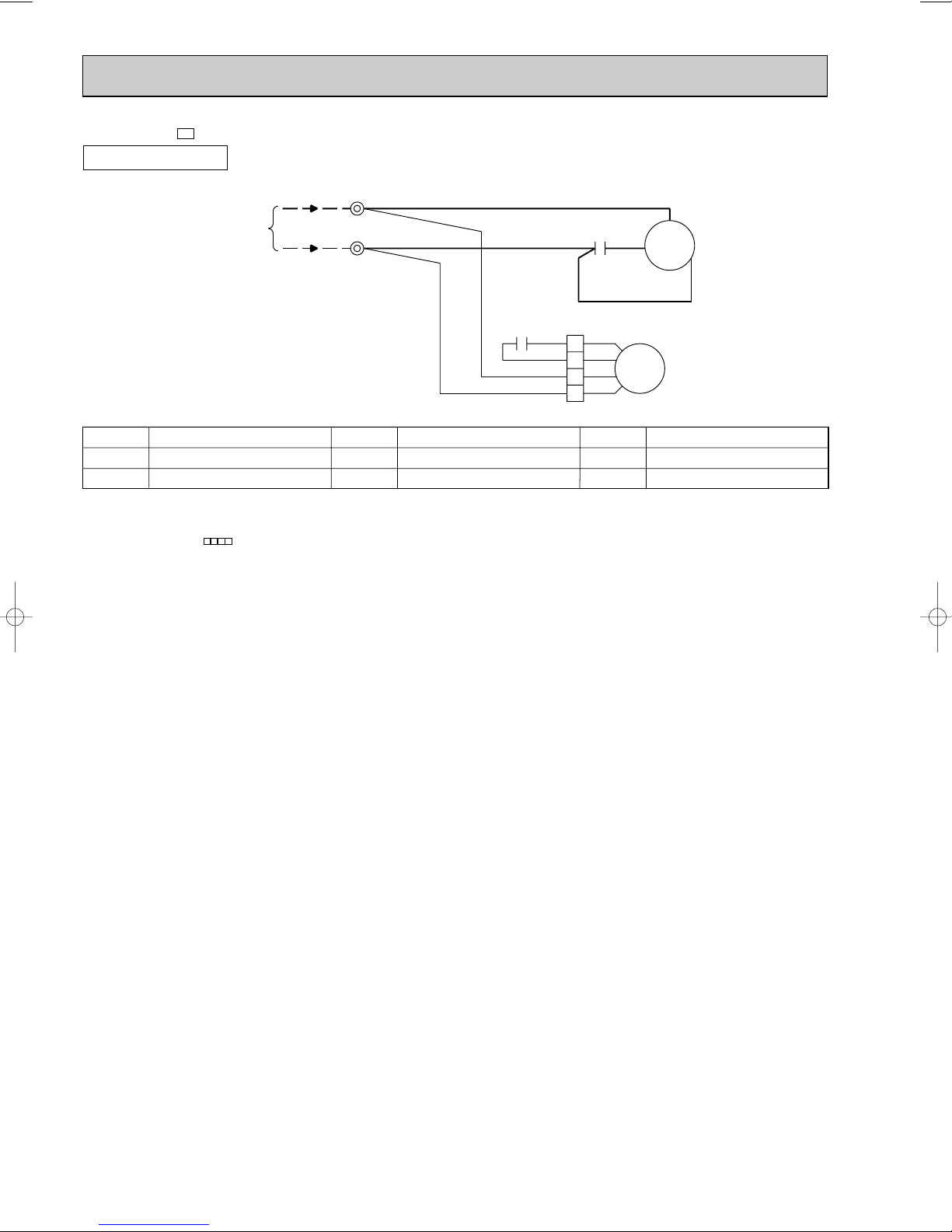
MU-18SN -
C1
OUTDOOR UNIT
FROM
INDOOR UNIT
CONNECTING
220V~
MODELS WIRING DIAGRAM
TB
2
C
WHT
BLU
C1
RED
BLK
C
MC
S
R
C2
RED
ORN
WHT
BLU
SYMBOL
C1
COMPRESSOR CAPACITOR
C2
OUTDOOR FAN CAPACITOR
NOTE:1. About the indoor side electric wiring refer to the indoor unit electric wiring diagram for servicing.
2.Use copper conductors only. (For field wiring)
3. Symbols below indicate.
/: Terminal block, : Connector
NAME
SYMBOL
MC
MF
NAME NAME
COMPRESSOR(INNER PROTECTOR)
OUTDOOR FAN MOTOR(INNER PROTECTOR)
RED
1
ORN
2
WHT
3
BLK
4
SYMBOL
MF
TERMINAL BLOCK
TB
VG79B106H01
16
Page 17
MS-24SN -
SYMBOL
RT12
TB
52C
SYMBOL
IC141
MF
MV
NR11
RT11
SYMBOL
C11
DSAR
F11
F12
HIC1
NAME
NAME NAME
INDOOR FAN CAPACITOR
SURGE ABSORBER
FUSE(3.15A)
THERMAL FUSE(93:)
DC/DC CONVERTER
HYBRID IC
INDOOR FAN MOTOR(INNER FUSE)
VANE MOTOR
VARISTOR
ROOM TEMPERATURE THERMIST OR
INDOOR COIL THERMISTOR
TERMINAL BLOCK
CONTACTOR
220V~
220V~
2
C
CN
151
CN
102
CN
101
3
5
MV
DISPLAY
P.C.BOARD
RECEIVER
P.C.BOARD
3
REMOTE
CONTROLLER
52C
RT12
IC141
112
CN
HIC1
NR11
TRANS
1
WHTWHT
DSAR
GRN/YLW
LD1
3
1
111
CN
ELECTRONIC CONTROLP.C. BOARD
4
2
1
C11
CN211
WHT
BLK
WHT
GRY
RED
RT11
F11
BLU
MF
3
121
CN
60Hz
1[ 220V~
CORD
POWER
SUPPLY
TO OUTDOOR
UNIT
CONNECTING
RED
3
GRN/YLW
TB
BLU
YLW
BRN
4
3
CN201
1
2
F12
BLU
BRN
BLU
BLU
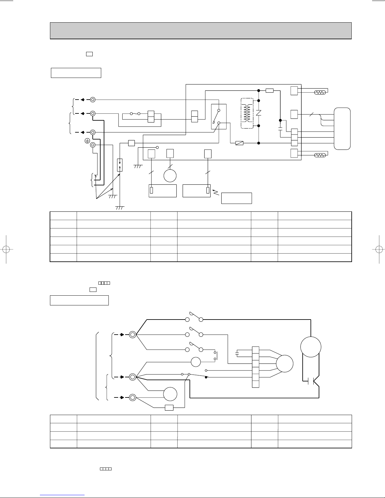
C1
INDOOR UNIT
MODEL WIRING DIAGRAM
NOTE:1. About the outdoor side electric wiring refer to the outdoor unit electric wiring diagram for servicing.
2. Use copper conductors only. (For field wiring)
3. Symbols below indicate.
/: Terminal block, : Connector
MU-24SN -
OUTDOOR UNIT
C1
MODEL WIRING DIAGRAM
TB
2
220V~
FROM INDOOR
UNIT
CCONNECTING
220V~
SYMBOL
CR
C1
C2
NOTE:1. About the indoor side electric wiring refer to the indoor unit electric wiring diagram for servicing.
2.Use copper conductors only. (For field wiring)
3. Symbols below indicate.
/: Terminal block, : Connector
CR SURGE ABSORBER
COMPRESSOR CAPACITOR
OUTDOOR FAN CAPACITOR
NAME
C
3
5
52C
1
52C
3
52C
RED
5
78
X1
RED
3
X1
1
BLU
NAME NAME
WHT
YLW
YLW
BLU
BLU
BLU
A2/b
RED
A1/a
RED
SYMBOL
MC
MF
TB
2
4
6
6
52C
GRY
CR
COMPRESSOR(INNER PROTECTOR)
OUTDOOR FAN MOTOR(INNER PROTECTOR)
TERMINAL BLOCK
17
C2
26F1
WHT
1
2
3
4
5
RED
ORN
WHT
BLK
MF
RED
ORN
WHT
BLK
YLW YLW
6
X1
26F1
52C
FAN MOTOR RELAY
THERMOSTAT(AIRFLOW CONTROL)
CONTACTOR
SYMBOL
RED
C
MC
RS
BLK
C1
Page 18
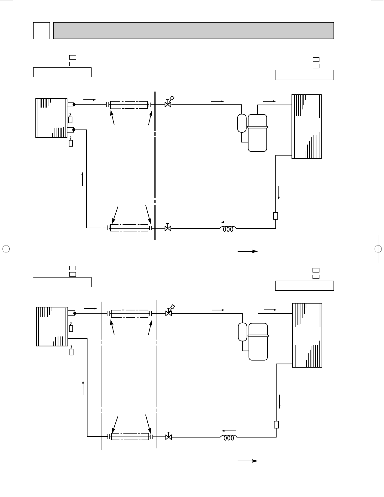
6
REFRIGERANT SYSTEM DIAGRAM
MS-09SN MS-09SN -
INDOOR UNIT
Indoor
heat
exchanger
Room temperature
thermistor
RT11
C1
C2
Indoor coil
thermistor
RT12
Refrigerant pipe [9.52
(Option)
(with heat insulator)
Flared connection
Flared connection
Stop valve
(with service port)
Stop valve
Compressor
Unit:mm
MU-09SN MU-09SN -
C1
C2
OUTDOOR UNIT
Outdoor
heat
exchanger
Strainer
MS-10SN MS-10SN -
INDOOR UNIT
Indoor
heat
exchanger
Room temperature
thermistor
RT11
C1
C2
Indoor coil
thermistor
RT12
Refrigerant pipe [6.35
(Option)
(with heat insulator)
Refrigerant pipe [9.52
(Option)
(with heat insulator)
Flared connection
Flared connection
Stop valve
(with service port)
Capillary tube
[3.0x[1.4x600
Compressor
Refrigerant flow in cooling
Unit:mm
MU-10SN MU-10SN -
C1
C2
OUTDOOR UNIT
Outdoor
heat
exchanger
Refrigerant pipe [6.35
(Option)
(with heat insulator)
Stop valve
18
Strainer
Capillary tube
[3.0x[1.6x900
Refrigerant flow in cooling
Page 19

Room
temperature
thermistor RT11
Flared
connector
Flared
connector
Refrigerant pipe {6.35
(Option)
(with heat insulator)
Refrigerant pipe {15.88
(Option)
(with heat insulator)
Refrigerant flow
Compressor
Accumulator
Stop valve
(with service port)
Stop valve
Strainer
Outdoor heat
exchanger
Distributor
MU-17SN- {3.0✕{2.0✕700
MU-18SN-
{
3.0✕{2.0✕500
C1
C1
MU-15SN- {3.0✕{1.8✕550
MU-15SN-
{
3.0✕
{1.8
✕550
C1
C2
Capillary tube
Indoor heat
exchanger
Indoor coil
thermistor
RT12
MS-12SN -
Room
temperature
thermistor RT11
Flared
connector
Flared
connector
Refrigerant pipe {6.35
(Option)
(with heat insulator)
Refrigerant pipe {12.7
(Option)
(with heat insulator)
Refrigerant flow
Compressor
Stop valve
(with service port)
Stop valve
Strainer
Outdoor heat
exchanger
Distributor
{3.0✕{1.8✕500
Capillary tube
Indoor heat
exchanger
Indoor coil
thermistor
RT12
MS-12SN -
INDOOR UNIT
Unit:mm
C1
C2
MU-12SN MU-12SN -
C1
C2
OUTDOOR UNIT
MS-15SN MS-15SN MS-17SN MS-18SN -
C1
C2
C1
C1
INDOOR UNIT
19
Unit:mm
MU-15SN MU-15SN MU-17SN MU-18SN -
C1
C2
C1
C1
OUTDOOR UNIT
Page 20

MS-24SN -
INDOOR UNIT
Indoor heat
exchanger
RT11
Room
temperature
thermistor
C1
Indoor coil
thermistor
RT12
Refrigerant pipe [15.88
(Option)
(with heat insulator)
Flared
connector
Flared
connector
Stop valve
(With service port)
Accumulator
[3.0 350[1.6
Discharge pressure
Compressor
regulator open
2.55MPa(26.0kgf/F)
Strainer
Unit:mm
MU-24SN -
C1
OUTDOOR UNIT
Outdoor heat
exchanger
Refrigerant pipe [9.52
Stop Valve
(Option)
(with heat insulator)
[3.0 600
[2.0
[3.0 100[2.0
Flow of refrigerant
20
Page 21

MAX. REFRIGERANT PIPING LENGTH
Refrigerant piping
Max. length : m
C1
C2
C1
C2
C1
C2
C1
C2
C1
C1
C1
A
15
MS-09SN MS-09SN MS-10SN MS-10SN MS-12SN MS-12SN MS-15SN MS-15SN MS-17SN MS-18SN MS-24SN -
Model
C1
C2
C1
C2
C1
C2
C1
C2
C1
C1
C1
MU-09SN MU-09SN MU-10SN MU-10SN MU-12SN MU-12SN MU-15SN MU-15SN MU-17SN MU-18SN MU-24SN -
Piping size O.D : mm Length of connecting pipe : m
Gas Liquid Indoor unit Outdoor unit
{9.52
{12.7
{15.88
{6.35
Gas 0.43
Liquid 0.5
Gas 0
Liquid 0
{9.52
MAX. HEIGHT DIFFERENCE
Indoor
unit
w Height difference should be within
7.5m regardless of which unit,
indoor or outdoor position is high.
w Max. Height
difference 7.5m
ADDITIONAL REFRIGERANT CHARGE(R22 : g)
Outdoor unit
precharged
C1
C2
C1
C2
C1
C2
C1
C2
C1
C1
C1
800
820
1200
1300
1350
1400
2150
7m
0
8m
15
MS-09SN MS-09SN MS-10SN MS-10SN MS-12SN MS-12SN MS-15SN MS-15SN MS-17SN MS-18SN MS-24SN -
Model
C1
C2
C1
C2
C1
C2
C1
C2
C1
C1
C1
MU-09SN MU-09SN MU-10SN MU-10SN MU-12SN MU-12SN MU-15SN MU-15SN MU-17SN MU-18SN MU-24SN -
Refrigerant Piping
Max.length
A
Refrigerant piping length (one way)
9m3010m
11m6012m7513m9014m
45
Outdoor unit
105
15m
120
21
Page 22

7
Wet-and dry-bulb
thermometers
Wet-and dry-bulb
thermometers
MS-10SN-
MS-12SN-
MS-12SN-
MS-15SN-
MS-15SN-
MS-18SN-
MS-17SN-
10.3
9.4
8.6
7.7
6.9
6.2
15.0
MS-24SN-
13.6
12.3
11.1
9.8
8.7
10.9
10.0
9.1
8.2
7.3
6.5
8.4
7.7
7.0
6.3
5.7
5.1
9.0
8.2
7.5
6.8
6.1
5.4
MS-10SN-
MS-09SN-
MS-09SN-
12.4
11.3
10.2
9.2
8.2
7.3
PERFORMANCE CURVES
MS-09SN MS-09SN MS-10SN MS-10SN -
C1
MS-12SN -
C2
MS-12SN -
C1
MS-15SN -
C2
MS-15SN -
C1
MS-17SN -
C2
MS-18SN -
C1
MS-24SN -
C2
C1
MU-09SN -
C1
MU-09SN -
C1
MU-10SN MU-10SN -
C1
MU-12SN -
C2
MU-12SN -
C1
MU-15SN -
C2
MU-15SN -
C1
MU-17SN -
C2
MU-18SN -
C1
MU-24SN -
C2
C1
C1
C1
The standard data contained in these specifications apply only to the operation of the air conditioner under normal conditions,
since operating conditions vary according to the areas where these units are installed. The following information has been provided to clarify the operating characteristics of the air conditioner under the conditions indicated by the performance curve.
(1) GUARANTEED VOLTAGE
198 ~ 242V
,60Hz
(2) AIR FLOW
Air flow should be set at MAX.
(3) MAIN READINGS
(1) Indoor intake air wet-bulb temperature : °CWB
(2) Indoor outlet air wet-bulb temperature : °CWB
(3) Outdoor intake air dry-bulb temperature : °CDB
(4) Total input: W
Indoor air wet/dry-bulb temperature difference on the left side of the chart on this page shows the difference between the
indoor intake air wet/dry-bulb temperature and the indoor outlet air wet/dry-bulb temperature for your reference at service.
How to measure the indoor air wet-bulb/dry-bulb temperature difference
1. Attach at least 2 sets of wet-and dry-bulb thermometers to the indoor air intake as shown in the figure, and at least 2 sets
of wet-and dry-bulb thermometers to the indoor air outlet. The thermometers must be attached to the position where air
speed is high.
2. Attach at least 2 sets of dry-bulb thermometers to the outdoor air intake.
Cover the thermometers to prevent direct rays of the sun.
3. Check that the air filter is cleaned.
4. Open windows and doors of the room.
5. Press the EMERGENCY OPERATION switch once to start the EMERGENCY COOL MODE.
6. When system stabilizes after more than 15 minutes, measure temperature and take an average temperature.
7. 10 minutes later, measure temperature again and check that the temperature does not change.
INDOOR UNIT
22
OUTDOOR UNIT
Page 23

OUTDOOR LOW PRESSURE AND OUTDOOR UNIT CURRENT
15 2050256030
70(%)
35(:)
2.5
3.0
3.5
4.0
4.5
18
32
15 20
50
25
60
30
70(%)
35(:)
0.3
0.4
0.5
0.6
0.7
18
32
7
6
5
4
3
18
32
7
6
5
4
3
2
15 20
50
256030
70(%)
35(:)
0.2
0.3
0.4
0.5
0.6
0.7
18 3215 2050256030
70(%)
35(:)
2.5
3.0
3.5
4.0
4.5
15 20
50
25
60
30
70(%)
35(:)
0.3
0.4
0.5
0.6
0.7
18 32
0.2
7
6
5
4
3
2
7.0
6.0
5.0
4.0
3.0
2.0
15 2050256030
70(%)
35(:)
18 32
COOL operation
① Both indoor and outdoor unit are under the same temperature/humidity condition.
Dry-bulb temperature(:)
Relative humidity(%)
20 50
25 60
30 70
➁ Air flow should be set at MAX.
③ The unit of pressure has been changed to MPa on the international system of units(SI unit system).
The conversion factor is : 1(MPa [Gauge]) =10.2(kgf/ff[Gauge])
(kgf/F[Gauge])(MPa[Gauge])
Outdoor low pressure
Ambient temperature(˚C)
Ambient humidity(%)
(kgf/F[Gauge])(MPa[Gauge])
MU-09SN MU-09SN -
MU-10SN MU-10SN -
C1
C2
MU-09SN MU-09SN -
Outdoor unit current (A)
Ambient temperature(˚C)
Ambient humidity(%)
C1
C2
MU-10SN MU-10SN -
C1
C2
C1
C2
Outdoor low pressure
Ambient temperature(˚C)
Ambient humidity(%)
(kgf/F[Gauge])(MPa[Gauge])
Outdoor low pressure
MU-12SN MU-12SN -
Ambient temperature(˚C)
Ambient humidity(%)
Outdoor unit current (A)
Ambient temperature(˚C)
Ambient humidity(%)
C1
C2
MU-12SN MU-12SN -
C1
C2
Outdoor unit current (A)
Ambient temperature(˚C)
Ambient humidity(%)
23
Page 24

15 20
50
25
60
30
70(%)
35(:)
18 32
0.3
0.4
0.5
0.6
0.7
0.2
3
4
5
6
7
2
14.0
13.0
12.0
11.0
10.0
9.0
15 20
50
25
60
30
70(%)
35(:)
18
32
8.0
7.0
6.0
5.0
4.0
3.0
15 20
50
25
60
30
70(%)
35(:)
18 32
15 205025
60
30
70(%)
35(:)
3
4
5
6
7
18
32
2
0.3
0.4
0.5
0.6
0.7
0.2
8.0
7.0
6.0
5.0
4.0
3.0
15 205025
60
30
70(%)
35(:)
18
32
15 20
50
25
60
30
70(%)
35(:)
18
32
0.3
0.4
0.5
0.6
0.7
0.2
3
4
5
6
7
2
(kgf/F[Gauge])(MPa[Gauge])
15
18 20
50
2560 30 32
70(%)
35(:)
5.0
6.0
7.0
8.0
9.0
10.0
18
32
3
4
5
6
7
2
15 20
25
30
70(%)
35(:)
0.2
0.3
0.4
0.5
0.6
0.7
MU-15SN MU-15SN -
C1
C2
MU-15SN MU-15SN -
C1
C2
Outdoor low pressure
Ambient temperature(˚C)
Ambient humidity(%)
(kgf/F[Gauge])(MPa[Gauge])
Outdoor low pressure
Ambient temperature(˚C)
Ambient humidity(%)
(kgf/F[Gauge])(MPa[Gauge])
MU-17SN -
MU-18SN -
Outdoor unit current(A)
Ambient temperature(˚C)
Ambient humidity(%)
C1
MU-17SN -
C1
Outdoor unit current(A)
Ambient temperature(˚C)
Ambient humidity(%)
C1
MU-18SN -
C1
Outdoor low pressure
Ambient temperature(˚C)
Ambient humidity(%)
(kgf/F[Gauge])(MPa[Gauge])
Outdoor low pressure
MU-24SN -
Ambient temperature(˚C)
Ambient humidity(%)
Outdoor unit current(A)
Ambient temperature(˚C)
Ambient humidity(%)
C1
MU-24SN -
C1
Outdoor unit current(A)
Ambient temperature(˚C)
Ambient humidity(%)
24
Page 25

8
Approx. 2 :
or more
Difference
between target
temperature
and room
temperature
Approx. 2 :
or less
This shows that the
air conditioner is
operating to reach
the target temperature.
Please wait until the
target temperature is
obtained.
This shows that the
room temperature is
approaching the
target temperature.
Operation stateIndication
lighted
not lighted
•The following indication applies regardless of shape of the indicator.
Operation Indicator
COOL mode of
"I FEEL CONTROL"
DRY mode of
"I FEEL CONTROL"
Initial room temperature
25: or more
more than 13:,
less than 25:
Mode
ON/OFF
FAN
TOO
WARM
TOO
COOL
VANE
MODE
ECONO COOL
STOP
START
HR.
MIN.
I FEEL
COOL
DRY
PM
CLOCK
AM
RESET
CLOCK
FAN
OPERATION SELECT button
FAN SPEED CONTROL button
OFF-TIMER button
HR. button
MIN. button
(TIME SET button)
ON-TIMER button
RESET button
ECONO COOL button
VANE CONTROL button
CLOCK SET button
ON/OFF
TOO
COOL
PM
AM
TOO
WARM
Signal transmitting section
Operation display section
OPERATE /STOP
(ON /OFF)button
TEMPERATURE buttons
MICROPROCESSOR CONTROL
MS-09SN MS-09SN MS-10SN MS-10SN -
C1
MS-12SN -
C2
MS-12SN -
C1
MS-15SN -
C2
MS-15SN -
C1
MS-17SN -
C2
MS-18SN -
C1
MS-24SN -
C2
WIRELESS REMOTE CONTROLLER
C1
MU-09SN -
C1
MU-09SN -
C1
MU-10SN MU-10SN -
C1
MU-12SN -
C2
MU-12SN -
C1
MU-15SN -
C2
MU-15SN -
C1
MU-17SN -
C2
MU-18SN -
C1
MU-24SN -
C2
Once the operation mode are set, the same operation mode
can be repeated by simply turning the
OPERATE/STOP(ON/OFF) button ON. Indoor unit receives
the signal with a beep tone.
When the system turns off, 3-minute time delay will operate to
protect system from overload and compressor will not restart
for 3 minutes.
8-1. “I FEEL CONTROL” ( ) OPERATION
(1) Press OPERATE/STOP(ON/OFF) button on the remote
controller. OPERATION INDICATOR lamp of the indoor
unit turns on with a beep tone.
(2) Select “I FEEL CONTROL”( ) mode with the OPERA-
TION SELECT button.
(3) The operation mode is determined by the room tempera-
ture at start-up of the operation.
● Once the mode is fixed, the mode does not change by
room temperature afterwards.
● Under the ON-TIMER ( ) operation, mode is deter-
mined according to the room temperature at set time the
operation starts.
● When the system is stopped on the remote controller
and restarted within 2 hours in “I FEEL CONTROL” ( )
mode, the system operates in previous mode automatically regardless of the room temperature.
C1
C1
C1
Operation Indicator lamp
The operation indicator located at the right side of the
indoor unit indicates the operation state.
INDOOR UNIT DISPLAY SECTION
Operation time chart
Example
Previous operation
COOL mode of
“I FEEL CONTROL”
Restart
COOL mode of
“I FEEL CONTROL”
or COOL mode
When the system is restarted after 2 hours and more,
the operation mode is determined by the room temperature at start-up of the operation.
Operation time chart
Example
Previous operation
COOL mode of
“I FEEL CONTROL”
or COOL mode
Restart
COOL or DRY mode of
“I FEEL CONTROL”
that determined by
room temperature at
start-up of the operation.
25
Page 26

Mode
COOL mode of
"I FEEL CONTROL"
DRY mode of
"I FEEL CONTROL"
Initial room temperature
Initial set temperature
more than 13:, less than 25:
24:
Initial room temperature
minus 2:
Initial room temperature
minus 2:
❈1
26: or more
25: to 26:
(4) The initial set temperature is decided by the initial room temperature.
TOO
COOL
TOO
WARM
❈1 When the system is restarted with the remote controller, the system operates with the previous set temperature regard-
less of the room temperature at restart.
The set temperature is calculated by the previous set temperature.
(5) TEMPERATURE buttons
In “I FEEL CONTROL” ( ) mode, set temperature is decided by the microprocessor based on the room temperature.
In addition, set temperature can be controlled by TOO WARM or TOO COOL buttons when you feel too cool or too
warm. Each time the TOO WARM or TOO COOL button is pressed, the indoor unit receives the signal and emits a
beep tone.
● Fuzzy control
When the TOO COOL or TOO WARM button is pressed, the microprocessor changes the set temperature, considering
the room temperature, the frequency of pressing TOO COOL or TOO WARM button and the user’s preference to heat
or cool. So this is called “Fuzzy control”, and works only in “I FEEL CONTROL” mode.
In DRY mode of “I FEEL CONTROL”, the set temperature doesn’t change.
…
To raise the set temperature 1~2 degrees(°C)
…
To lower the set temperature 1~2 degrees(°C)
8-1-1. COOL mode of “I FEEL CONTROL”
1. Indoor fan speed control
Indoor fan operates continuously at the set speed by FAN SPEED CONTROL button regardless of thermostat’s OFF-ON.
In Auto the fan speed is as follows.
MS-09/10/12/15/17/24SN-
C1
Room temperature minus set temperature : 2 degrees or more·······························High
Room temperature minus set temperature : Between 1 and 2 degrees···················Med.
Room temperature minus set temperature : less than 1 degree·······························Low
MS-09/10/12/15SN- , MS-18SN-
C1C2
Room temperature minus set temperature : 1.7 degrees or more·······························High
Room temperature minus set temperature : Between 1 and 1.7 degrees···················Med.
Room temperature minus set temperature : less than 1 degree··································Low
2. Coil frost prevention
① Temperature control
When the indoor coil thermistor RT12 reads 4°C or below(MS-09/10SN) / -1°C or below(MS-12/15/17/18/24SN) for 5 minutes, the coil frost prevention mode starts.
The indoor fan operates at the set speed and the compressor stops for 5 minutes.
After that, if RT12 still reads below 4°C(MS-09/10SN) / or below -1°C(MS-12/15/17/18/24SN), this mode is prolonged until
the RT12 reads over 4°C(MS-09/10SN) / -1°C(MS-12/15/17/18/24SN).
② Time control
When the three conditions as follows have been satisfied for 1 hour and 45 minutes, the compressor stops for 3 minutes.
The indoor fan operates at the set speed.
a. Compressor has been continuously operating.
b. Indoor fan speed is Low or Med..
c. Room temperature is below 26°C.
Initial temperature difference
Initial temperature difference
26
Fan speed
Fan speed
Difference between room
temperature and set temperature during operation
2 deg.
4 deg.
1.7 deg.
1 deg.
Difference between room
temperature and set temperature during operation
3 deg.
1.7 deg.
1 deg.
Page 27

When compressor stops, the accumulated time is cancelled. When compressor restarts, time counting starts from the
Outdoor fan speed
High
Low
Temperature of thermostat 26F1
28.5:
31:
beginning.
Time counting also stops temporarily when the indoor fan speed becomes High or the room temperature exceeds
26°C. However, when two of the above conditions (b.and c.) are satisfied again, time accumulation is resumed.
Operation chart
Example
ON
ON
Compressor
Outdoor fan
Indoor fan
3. Outdoor fan speed control MU-24SN
Outdoor fan speed is controlled according to the temperature of thermostat 26F1.
Outdoor fan High operation : Until the outside temperature decrease 28.5:.
Outdoor fan Low operation : When the outside temperature decrease to 28.5:.
8-1-2. DRY mode of “I FEEL CONTROL”
The system for dry operation uses the same refrigerant circuit as the cooling circuit.
The compressor and the indoor fan are controlled by the room temperature.
By such controls, indoor flow amounts will be reduced in order to lower humidity without much room temperature decrease.
1. Indoor fan speed control
Indoor fan operates at the set speed by FAN SPEED CONTROL button.
In Auto fan speed becomes Low.
2. The operation of the compressor and indoor / outdoor fan
Compressor operates by room temperature control and time control.
Set temperature is controlled to fall 2°C from initial room temperature.
Indoor fan and outdoor fan operate in the same cycle as the compressor.
● When the room temperature is 23°C or over.
When the thermostat is ON, the compressor repeats 8 minutes ON and 3 minutes OFF.
When the thermostat is OFF, the compressor repeats 4 minutes OFF and 1 minute ON.
● When the room temperature is under 23°C.
When the thermostat is ON, the compressor repeats 2 minutes ON and 3 minutes OFF.
When the thermostat is OFF, the compressor repeats 4 minutes OFF and 1 minute ON.
OFF
ON
( continuously at set speed)
When the outside temperature goes to 31:.
Until the outside temperature goes to 31:.
OFF
Operation time chart
Example
Thermostat
Indoor fan
Outdoor fan
Compressor
3. Coil frost prevention
The operation is as same as coil frost prevention during COOL mode of “I FEEL CONTROL” operation.(Refer to 8-1-1.
COOL mode of “I FEEL CONTROL” 2.)
However when coil frost prevention works while the indoor fan is OFF, it’s speed becomes set speed.
OFF
OFF
8-2. COOL ( ) OPERATION
(1) Press OPERATE/STOP(ON/OFF) button. OPERATION INDICATOR lamp of the indoor unit turns on with a beep tone.
(2) Select COOL mode with the OPERATION SELECT button.
(3) Press TEMPERATURE buttons (TOO WARM or TOO COOL button) to select the desired temperature.
The setting range is 16 ~ 31°C.
ON
OFF
OFFOFF
OFF
ON
ON
3 min.
ON
OFF
ON
OFF
4 min.
27
ON
ON
8 min. 1 min.
ON
Page 28

35
30
25
20
15
10
:
10 15 20 25 30 35
Set temperature
Initial room temperature
Set temperature and
initial room temperature in dry mode
:
High
Med.
Low
High
Time
1. Indoor fan speed control
Indoor fan speed control is as same as COOL mode of “I FEEL CONTROL”.(Refer to 8-1-1. COOL mode of I FEEL CON-
TROL” 1.)
2. Coil frost prevention
Coil frost prevention is as same as COOL mode of “I FEEL CONTROL”.(Refer to 8-1-1. COOL mode of I FEEL CONTROL”
2.)
8-3. DRY ( ) OPERATION
(1) Press OPERATE/STOP(ON/OFF) button.
OPERATION INDICATOR lamp of the indoor unit turns on with a
beep tone.
(2) Select DRY mode with the OPERATION SELECT button.
(3) The microprocessor reads the room temperature and determines
the set temperature. Set temperature is as shown on the right chart.
DRY operation will not function when the room temperature is 13°C
or below.
(4) When DRY operation functions the fan speed is lower than cool
operation expect at (fan speed) Low notch.
1. Indoor fan speed control
Indoor fan speed control is as same as DRY mode of “I FEEL CON-
TROL”.(Refer to 8-1-2. DRY mode of I FEEL CONTROL” 1.)
2. The operation of the compressor and indoor / outdoor fan
The operation of the compressor and indoor / outdoor fan is as same
as DRY mode of “I FEEL CONTROL”.(Refer to 8-1-2. DRY mode of
I FEEL CONTROL” 2.)
3. Coil frost prevention
Coil frost prevention is as same as DRY mode of “I FEEL CONTROL”.(Refer to 8-1-2. DRY mode of I FEEL CONTROL” 3.)
8-4. FAN ( ) OPERATION
(1) Press OPERATE/STOP(ON/OFF) button. OPERATION INDICATOR lamp of the indoor unit turns on with a beep tone.
(2) Select FAN mode with the OPERATION SELECT button.
(3) Select the desired fan speed. When AUTO, it becomes Low.
Only indoor fan operates.
Outdoor unit does not operate.
8-5. FAN MOTOR CONTROL
(1) Rotational frequency feedback control
The indoor fan motor is equipped with a rotational frequency sensor, and outputs signal to the microprocessor to feedback
the rotational frequency. Comparing the current rotational frequency with the target rotational frequency (High, Med., Low),
the microprocessor controls SR141 (MS-09/10SN) IC141 (MS-12/15/17/18/24SN) and adjusts fan motor electric current to
make the current rotational frequency close to the target rotational frequency. With this control, when the fan speed is
switched, the rotational frequency changes smoothly.
(2) Fan motor lock-up protection
When the rotational frequency feedback signal is not output for 12 seconds, (or when the microprocessor cannot detect
the signal for 12 seconds) the fan motor is regarded locked-up. Then the electric current to the fan motor is shut off. 3 minutes later, the electric current is applied to the fan motor again. During the fan motor lock-up, the OPERATION INDICATOR lamp flashes on and off to show the fan motor abnormality. (Refer to page 35.)
8-6. AUTO VANE OPERATION
(1) Vane motor drive
These models are equipped with a stepping motor for the horizontal vane. The rotating direction, speed, and angle of
the motor are controlled by pulse signals (approx. 12V) transmitted from indoor microprocessor.
(2) The horizontal vane angle and mode changes as follows by pressing the VANE CONTROL button.
28
Page 29

(3) Positioning
The vane is once pressed to the vane stopper below to confirm the standard position and then set to the desired angle.
Confirming of standard position is performed in case of follows.
(a) When the OPERATE / STOP(ON / OFF) button is pressed.
(b) When the vane control is changed from AUTO to MANUAL.
(c) When the SWING is finished.
(d) When the test run starts.
(e) When the power supply turns ON.
(4) VANE AUTO ( ) mode
In VANE AUTO mode, the microprocessor automatically determines the vane angle to make the optimum room-temperature distribution.
1 In COOL and DRY operation
Vane angle is fixed to Angle 1.
2 In FAN operation
Vane angle is fixed to Angle 4.
(5) Dew prevention
During COOL or DRY operation at Vane Angle 4 or 5 when the cumulative operation time of compressor exceeds 1
hour, the vane angle automatically changes to Angle 1 for dew prevention.
(6) SWING MODE ( )
By selecting SWING mode with the VANE CONTROLbutton, the horizontal vane swings vertically. The remote controller
displays “ ”.
(7) ECONO COOL ( ) operation (ECONOmical operation)
When the ECONO COOL button is pressed in COOL mode, set temperature is automatically set 2°C higher than that in
COOL mode.
Also the horizontal vane swings in various cycle according to the temperature of indoor heat exchanger(RT12).
SWING operation makes you feel cooler than set temperature. So, even though the set temperature is higher than that
in COOL mode, the air conditioner can keep comfort. As a result, energy can be saved.
ECONO COOL operation is cancelled when the ECONO COOL button is pressed once again or VANE CONTROL button is pressed or change to other operation mode.
NOTE : ECONO COOL operation not work in COOL mode of “I FEEL CONTROL”.
SWING operation
In swing operation of ECONO COOL mode, the initial air flow direction is adjusted to “Horizontal”.
According to the temperature of indoor coil thermistor RT12 at starting of this operation, next downward blow time is
decided. Then when the downward blow has been finished, next horizontal blow time is decided.
For initial 10 min. the swing operation is performed in table G~H for quick cooling.
Also, after 10 min. when the difference of set temperature and room temperature is more than 2 degrees, the swing
operation is performed in table D~H for more cooling.
The air conditioner repeats the swing operation in various cycle as follows.
Temperature of indoor coil
thermistor RT12 (:)
A
B
C
D
E
F
G
H
15°C or less
15°C to 17°C
17°C to 18°C
18°C to 20°C
20°C to 21°C
21°C to 22°C
22°C to 24°C
more than 24°C
Downward blow time
(sec.)
2
5
8
11
14
17
20
23
Horizontal blow time
(sec.)
23
20
17
14
11
8
5
2
29
Page 30

8-7. TIMER OPERATION
PM
AM
PM
PM
1. How to set the timer
(1) Press OPERATE/STOP(ON/OFF) button to start the air conditioner.
(2) Check that the current time is set correctly.
NOTE : Timer operation will not work without setting the current time. Initially “AM 0:00” blinks at the current time display of
TIME MONITOR, so set the current time correctly with CLOCK SET button.
(3) Press ON or OFF TIMER buttons to select the operation.
ON-TIMER button... AUTO START operation (ON timer)
OFF-TIMER button... AUTO STOP operation (OFF timer)
(4) Press HR. and MIN. button (TIME set button) to set the timer. Time setting is 10-minute units.
HR. and MIN. button will work when “ ” or “ ” mark is flashing.
These marks disappear in 1 minute.
After setting the ON timer, check that OPERATION INDICATOR lamp of the indoor unit lights.
NOTE1 : Be sure to place the remote controller at the position where its signal can reach the air conditioner even during
TIMER operation, or the set time may deviate within the range of about 10 minutes.
NOTE2 : Reset the timer in the following cases, or the set time may deviate and other malfunctions may occur.
● A power failure occurs.
● The circuit breaker functions.
2. Cancel
TIMER setting can be cancelled with the ON or OFF TIMER buttons.
To cancel the ON timer, press the ON-TIMER button.
To cancel the OFF timer, press the OFF-TIMER button.
TIMER is cancelled and the display of set time disappears.
PROGRAM TIMER
● The OFF timer and ON timer can be used in combination.
● “ ” and “ ” display shows the order of the OFF timer and ON timer operation.
(Example 1) The current time is 8:00 PM.
The unit turns off at 11:00 PM, and on at 6:00 AM.
(Example 2) The current time is 11:00 AM.
The unit turns on at 5:00 PM, and off at 9:00 PM.
NOTE : TIMER setting will be cancelled by power failure or breaker functioning.
30
Page 31

8-8. EMERGENCY-TEST OPERATION
In case of test run operation or emergency operation, use the EMERGENCY OPERATION switch on the front of the
indoor unit. Emergency operation is available when the remote controller is missing, has failed or the batteries of remote
controller run down. The unit will start and the OPERATION INDICATOR lamp will light.
The first 30 minutes of operation is the test run operation. This operation is for servicing. The indoor fan speed runs at
High speed and the system is in continuous operation. (The thermostat is ON.)
After 30 minutes of test run operation the system shifts to EMERGENCY COOL MODE with a set temperature of 24°C.
The fan speed shifts to Med. speed.
The coil frost prevention works even in emergency operation.
In the test run or emergency operation, the horizontal vane operates in VANE AUTO ( ) mode.
Emergency operation continues until the EMERGENCY OPERATION switch is pressed again or the unit receives any signal from the remote controller. In case of latter normal operation will start.
NOTE : Do not press the EMERGENCY OPERATION switch during normal operation.
MS-09/10SN
MS-12/15/17/18/24SN
•The following indication applies
regardless of shape of the indicator.
OPERATION INDICATOR lamp
Press once <Cool>
Press once again <Stop>
EMERGENCY OPERATION switch
EMERGENCY OPERATION switch
31
Page 32

No. 1 unit
No. 2 unit
No. 3 unit
No. 4 unit
1 unit operation
No modification
–
–
–
2 units operation
Same as at left
Solder J1
–
–
3 units operation
Same as at left
Same as at left
Solder J2
–
4 units operation
Same as at left
Same as at left
Same as at left
Solder both J1 and J2
9
SERVICE FUNCTIONS
MS-09SN MS-09SN MS-10SN MS-10SN -
C1
MS-12SN -
C2
MS-12SN -
C1
MS-15SN -
C2
MS-15SN -
C1
MS-17SN -
C2
MS-18SN -
C1
MS-24SN -
C2
C1
C1
C1
9-1. TIMER SHORT MODE
For service, set time can be shortened by short circuit of JPG and JPS the electronic control P.C. board.
The time will be shortened as follows. (Refer to page 40 or 41.)
Set time : 1-minute ➔ 1-second
Set time : 3-minute ➔ 3-second (It takes 3 minutes for the compressor to start operation. However, the starting time is
shortened by short circuit of JPG and JPS.)
9-2. P.C. BOARD MODIFICATION FOR INDIVIDUAL OPERATION
A maximum of 4 indoor units with wireless remote controllers can be used in a room.
In this case, to operate each indoor unit individually by each remote controller, P.C. boards of remote controller must be
modified according to the number of the indoor unit.
How to modify the remote controller P.C. board
Remove batteries before modification. The board has a print as shown below :
The P.C.board has the print “J1” and “J2”. Solder “J1” and “J2” according to the number of indoor unit as shown in Table 1.
After modification, push the RESET button.
Table 1
How to set the remote controller exclusively for particular indoor unit
After you turn the breaker ON, the first remote controller that sends the signal to the indoor unit will be regarded as the
remote controller for the indoor unit.
The indoor unit will only accepts the signal from the remote controller that has been assigned to the indoor unit once they
are set.
The setting will be cancelled if the breaker has turned off, or the power supply has shut down.
Please conduct the above setting once again after the power has restored.
32
NOTE : For remodelling, take out the batter-
ies and push the
OPERATE/STOP(ON/OFF) button
twice or 3 times at first.
After finish remodelling, put back
the batteries then push the RESET
button.
Page 33

C111
CN201
C11
CN211
IC152
CN151
SW1
CN112
CN121
IC101
CN111
JR07
52C
MS-09/10SN
IC141
C11
CN211
CN101
CN151
SW
CN111
CN121
IC101
JR06
52C
MS-12/15/17/18/24SN
RA102
RA102
CN201
BZ
CN102
CN112
9-3. AUTO RESTART FUNCTION
When the indoor unit is controlled with the remote controller, the operation mode, the set temperature, and the fan speed
are memorized by the indoor electronic control P.C.board. The “AUTO RESTART FUNCTION” sets to work the moment the
power has restored after power failure. Then, the unit will restart automatically. However if the unit is operated in “I FEEL
CONTROL” mode before power failure, the operation is not memorized. In “I FEEL CONTROL” mode, the operation is
decided by the initial room temperature.
How to set “AUTO RESTART FUNCTION”
1 Turn off the main power for the unit.
2 Pull out the indoor electronic control P.C. board and the display P.C.board. (Refer to page 42 or 44.)
3 Cut the RESISTOR JR07(MS-09/10SN) or JR06(MS-12/15/17/18/24SN) on the indoor electronic control P.C.board.
(Refer to page 40 or 41.)
Operation
1 If the main power (220V AC) has been cut, the operation settings remain.
2 After the power is restored, the unit restarts automatically according to the memory.(However, it takes at least 3 minutes
for the compressor to start running.)
NOTE
•The operation settings are memorized when 10 seconds have passed after the indoor unit was operated with the remote
controller.
•If the main power is turned off or a power failure occurs while AUTO START/STOP timer is active, the timer setting is
cancelled.
•If the unit has been off with the remote controller before power failure, the auto restart function does not works as the
power button of the remote controller is off.
•To prevent breaker off due to the rush of starting current, systematize other home appliances not to turn on at the same
time.
•When some air conditioners are connected to the same supply system, if they are operated before power failure, the
starting current of all the compressors may flow simultaneously at restart.
Therefore, the special counter-measures are required to prevent the main voltage-drop or the rush of the starting current
by adding to the system that allows the units to start one by one.
33
Page 34

10 TROUBLESHOOTING
Lead wiring
Housing point
Insert the negative pole
of the batteries first.
Check if the polarity of
the batteries is correct.
RESET button
MS-09SN MS-09SN MS-10SN MS-10SN -
C1
MS-12SN -
C2
MS-12SN -
C1
MS-15SN -
C2
MS-15SN -
C1
MS-17SN -
C2
MS-18SN -
C1
MS-24SN -
C2
C1
MU-09SN -
C1
MU-09SN -
C1
MU-10SN MU-10SN -
C1
MU-12SN -
C2
MU-12SN -
C1
MU-15SN -
C2
MU-15SN -
C1
MU-17SN -
C2
MU-18SN -
C1
MU-24SN -
C2
10-1. Cautions on troubleshooting
1. Before troubleshooting, check the following:
1) Check the power supply voltage.
2) Check the indoor/outdoor connecting wire for mis-wiring.
2. Take care the following during servicing.
1) Before servicing the air conditioner, be sure to first turn off the remote controller to stop the main unit, and then after
confirming the horizontal vane is closed, turn off the breaker and / or disconnect the power plug.
2) Be sure to unplug the power supply cord before removing the front panel, the cabinet, the top panel, and the electronic control P.C. board.
3) When removing the electronic control P.C. board, hold the edge of the board with care NOT to apply stress on the
components.
4) When connecting or disconnecting the connectors, hold the housing of the connector. DO NOT pull the lead wires.
3. Troubleshooting procedure
1) First, check if the OPERATION INDICATOR lamp on the indoor unit is flashing on and off to indicate an abnormality.
To make sure, check how many times the abnormality indication is flashing on and off before starting service work.
2) Before servicing check that the connector and terminal are connected properly.
3) If the electronic control P.C. board is supposed to be defective, check the copper foil pattern for disconnection and
the components for bursting and discoloration.
4) When troubleshooting, refer to the flow chart and the check table on page 35.
4. How to replace batteries
Weak batteries may cause the remote controller malfunction.
In this case, replace the batteries to operate the remote controller normally.
1 Remove the front lid and insert batteries.
Then re-attach the front lid.
2 Press the RESET button with tip end of ball point pen
or the like, and then use the remote controller.
C1
C1
C1
NOTE : If the RESET button is not pressed, the remote controller may not operate correctly.
34
Page 35

10-2. Instruction of troubleshooting
•The following indication applies regardless of shape of the indicator.
Operation Indicator
flashing
Start
Indoor unit
operates.
Outdoor unit
doesn't
operate.
Indoor unit
doesn't receive
the signal from
remote controller.
OPERATION INDICATOR
lamp on the indoor unit is
flashing on and off.
Outdoor unit
operates in
only Test Run
operation.
Outdoor unit
doesn't
operate
even in
Test Run
operation.
Indoor unit
operates, when
the EMERGENCY
OPERATION
switch is pressed.
Indoor unit
doesn't operate,
when the
EMERGENCY
OPERATION
switch is pressed.
Check room
temperature
thermistor.
Refer to
"Test point
diagram and
voltage" on
page 40 or 41.
Refer to D
"Check of
outdoor unit"
on page 38
or 39.
Refer to B
"Check of
remote controller
and power
monitor, receiver
P.C. board"
on page 37.
1. Check indoor /
outdoor
connecting wire.
2. Refer to C
"Check of indoor
electronic control
P.C. board"
on page 38.
2-time flash
Cause:
Indoor unit
• Trouble of
room temp erature/
indoor coil
thermistor
3-time flash
Cause:
Indoor unit
• Trouble of
indoor fan
motor
Check room
temperature
thermistor and
indoor coil
thermistor.
Refer to "Test
point diagram
and voltage" on
page 40 or 41.
Refer to A
"Check of
indoor fan
motor"
on page 37.
1. Troubleshooting check table
NOTE : Before taking measures, make sure that the symptom reappears, for accurate troubleshooting.
Self check table
Abnormal
NO.
point
Indoor coil
thermistor
1
Room
temperature thermistor
Indoor fan
2
motor
2-time flash
3-time flash
Indication
2.5-second OFF
2.5-second OFF
· Flashing of the OPERATION INDICATOR lamp (on the left-hand side)
indicates possible abnormalities.
· The OPERATION INDICATOR lamp (on the left-hand side) is lighting
during normal operation.
Symptom
Outdoor unit
does not run.
Indoor fan motor
repeats 12 seconds ON and 3
minutes OFF.
When the indoor
fan motor
breaks, the fan
keeps stopping.
35
Detect method
Detect Indoor coil/room temperature thermistor short or
open circuit every 8 seconds
during operation.
When rotational frequency
feedback pulse signal is not
emit during 12-second indoor
fan operation.
● Check resistance of thermistor.
● Re-connect connector.
● Check indoor electronic control P.C.board.
● Disconnect connector CN211 and then
check connector CN121 - to make
sure rotational frequency feedback signal
of 1.5V or over exists.
● Check indoor electronic control P.C.
board.
● Check indoor fan motor.
● Re-connect connector.
Check point
2
3
Page 36

RED
YLW
BRN
ORN
GRN
ROTOR
P
R
C
S
RED
BLK
WHT
MAINAUX.
2. Trouble criterion of main parts
BLK
FUSE
WHT
RED
B
R
N
G
R
Y
Y
L
W
RED
ORN
WHT
MU-24SN
BLKYLW
P
WHTRED
BLK
MAIN
AUX.
P
WHTRED
BLK
MAIN
AUX.
P
MU-15/17/18SN
MU-09/10/12SN
ORN
C1
MS-09SN MS-09SN MS-10SN MS-10SN -
MS-12SN -
C2
MS-12SN -
C1
MS-15SN -
C2
MS-15SN -
Part name
Room
temperature
thermistor(RT11)
Measure the resistance with a tester.
(Part temperature 10°C ~ 30°C)
Indoor coil
thermistor(RT12)
Compressor
(MC)
INNER
PROTECTOR
MU-09/10/12/15SN
i10: CLOSE
90
150i 5: OPEN
MU-17/18SN
95i10: CLOSE
150i10: OPEN
MU-24SN
102i15: CLOSE
165i 8: OPEN
Measure the resistance between the terminals with a tester.
(Coil wiring temperature 10°C ~ 40°C)
Terminal
MU-09SN MU-10SN MU-12SN MU-15SN MU-17SN MU-18SN MU-24SN
2.81~3.45Ω 2.41~2.96Ω 1.9~2.34Ω 1.48~1.82Ω 1.45~1.79Ω 1.21~1.49Ω 0.73~0.90Ω
C-R
C-S
3.13~3.83Ω 3.33~4.08Ω 2.74~3.36Ω 2.45~3.0Ω 2.35~2.89Ω 2.25~2.75Ω 1.61~1.97Ω
Measure the resistance between the terminals with a tester.
(Coil wiring temperature10°C ~ 30°C)
lead wire
Indoor fan
motor(MF)
Motor part
WHT-BLK
BLK-RED
INNER FUSE
MS-09/10SN
136i3: CUT OFF
MS-12/15/17/18/24SN
145i2: CUT OFF
Measure the voltage Power ON.
Color of lead wire
BRN-YLW
Sensor part
YLW-GRY
C1
C2
C1
C2
Color of
C1
MS-17SN MS-18SN MS-24SN -
MU-09SN -
C1
MU-09SN -
C1
MU-10SN MU-10SN -
Check method and criterion
Normal
8kΩ ~ 20kΩ
Normal
Normal
MS-09/10SN
321~349Ω 113~123Ω
307~333Ω
Normal
4.5 ~ 5.5V
(When fan revolved one time)
0V➔5V➔0V
(Approx.)
MS-12/15/17/18/24SN
C1
MU-12SN -
C2
MU-12SN -
C1
MU-15SN -
C2
MU-15SN -
Abnormal
Open or short-circuit
155~169Ω
Abnormal
Remain 0V or 5V
Abnormal
Open or
short-circuit
Abnormal
Open or
short-circuit
C1
MU-17SN -
C2
MU-18SN -
C1
MU-24SN -
C2
C1
C1
C1
Figure
Measure the resistance between the terminals with a tester.
(Coil wiring temperature 10°C ~ 40°C)
Color of
lead wire
WHT-BLK
BLK-RED
MU-09SN
149~183Ω
199~244Ω
BLK-YLW
Outdoor fan
motor(MF)
INNER
PROTECTOR
MU-09/10/12SN
95i15: CLOSE
135i 5: OPEN
MU-15/17/18SN
120i 5: OPEN
MU-24SN
135i 5: OPEN
Measure the resistance between the terminals with a tester.
Vane motor(MV)
(Part temperature10°C ~ 30°C)
MS-09/10SN 282 ~ 306Ω
MS-12/15/17/18/24SN 358 ~ 387Ω
MU-10/12SN
132~162Ω
233~286Ω
Normal
Normal
MU-15SN
102~126Ω
97~120Ω
36
MU-17/18SN
102~126Ω
97~120Ω
71.5~87.5Ω
90.2~110.2Ω
Open or short-circuit
MU-24SN
81.3~99.4Ω
Abnormal
Abnormal
Open or
short-circuit
PP
:INNER PROTECTOR
Page 37

When OPERATION INDICATOR lamp flashes 3-time.
Indoor fan motor doesn’t operate.
A
Check of indoor fan motor
Turn OFF the power supply.
Check connector CN211 visually.
No
Re-connect the lead wires.
Are lead wires connected?
Disconnect lead wires from connector CN211 on indoor electronic control P.C. board.
Measure resistance between lead wires No.1 and No.3 and then No.2 and No.3(MS-09/10SN)
Yes
{
No.1 and No.4 and then No.1 and No.2(MS-12/15/17/18/24SN)
Is resistance 0 (short circuit) or ∞ (open circuit)?
Yes ( 0 or ∞ )
Repair the indoor fan motor.
Replace the indoor electronic control P.C. board.
Is soldered point of connector normal?
Yes
Insert screwdriver into air outlet to
rotate indoor fan motor slowly for 1
revolution or over, and measure
No
voltage between YLW and GRY of
(others)
CN121.
No
Does voltage repeat 0V
Yes
Indoor unit operates by pressing the EMERGENCY OPERATION switch, but does not operate
with the remote controller.
Check of remote controller and power monitor, receiver P.C. board
B
Switch on the remote controller.
w Check the remote controller is exclusive
for this air conditioner.
Is LCD display on the remote controller visible?
Yes
Remove the batteries, then set them back
and press the RESET button. Check if the
unit operates with the remote controller.
No
(not clear)
Replace the batteries.(Refer to page 34.)
w In case of replacing the receiver P.C.
board of MS-09SN or MS-10SN replace
the indoor electronic control P.C. board
with it because they are unified.
No
Re-solder it.
}
DC and more than 5V?
Does the unit operate with the
remote controller?
Yes
OK
No
(MS-09/10SN)
Replace the indoor electronic control P.C.
board with power monitor, receiver P.C. board.
No
Turn on a radio to AM and press switch on
the remote controller.
Is noise heard from radio?
Yes
Are there any fluorescent lights of
inverter or rapid-start type within
the range of 1m?
No
(MS-12/15/17/18/24SN)
Measure the voltage between indoor receiver P.C. board connector No.2
No.1 when remote controller button is pressed.
Is the voltage approx. 4V DC?
No(5V or 0V DC)
Replace the receiver P.C. board.
No
Yes
Yes
37
Replace the remote controller.
• Re-install the unit away from lights.
• Attach a filter on receiving part.
(+)
and
Replace the indoor electronic control P.C.
board.
Page 38

Replace the fuse.
Is fuse(F11) blown?
Be sure to check both fuse
and varistor in any case.
Replace the fan motor.
Replace the
indoor electronic
control P.C. board.
Is winding resistance
of fan motor 0 "?
Is winding resistance
of vane motor 0 "?
No
Yes
Replace the vane motor.
No
Yes
Yes
Is varistor(NR11) burnt?
Replace the varistor.
Yes
Turn OFF the power supply.
Remove indoor fan motor connector CN211 and
vane motor connector CN151 from the indoor electronic
control P.C. board and turn ON the power supply.
No
No
Yes
No
Is resistance approx. 0"?
Replace the fuse (F12).
CN201
1
2
L1
F12
1
3
Terminal
block
Be sure to check both resistances.
No (∞)
Yes
Turn OFF the
power supply.
Turn OFF the
power supply.
Check both “parts side”and “pattern side” of indoor
electronic control P.C. board visually.
Does the unit operate with the remote controller?
Does the OPERATION INDICATOR lamp light up
by pressing the EMERGENCY OPERATION switch?
Measure the
resistance between
CN201
1 on the
indoor electronic
control P.C. board and
L1
(MS-09/10/12/15/17/18SN)/
c (MS-24SN) on the
terminal block with
the tester.
C
MS-09/10/12/15/17/18SN
MS-24SN
(
)
The unit doesn’t operate with the remote controller.
Start
No
Turn ON the power supply.
Press the EMERGENCY OPERATION switch.
3-minute time delay works.
Test run operation operates for 30 minutes.
Yes
Yes
Outdoor unit does not
operate.
Is the connection of wiring
in outdoor unit correct?
Check the outdoor
fan motor and compressor.
Refer to page 36.
Make the connection of
wiring in outdoor unit
correct.
No
Check the voltage to terminal block of
indoor unit. Is there 220V AC to
terminal block between
2-C?
Reconnect the continuity of indoor and
outdoor unit connection.
Yes
Replace the indoor electronic
control P.C. board.
Compressor
does not operate.
No
Yes
Is the connection of wiring
from terminal block to
compressor correct ?
Check the compressor.
Refer to page 36.
Make the connection of
wiring from terminal block
to compressor correct .
Outdoor fan motor
does not operate.
No
Yes
Is the connection of wiring
from terminal block to
outdoor fan motor correct ?
Check the outdoor fan motor.
Refer to page 36.
Make the connection of
wiring from terminal block
to outdoor fan motor
correct .
No
Does outdoor unit operate?
Yes
Ok
No
Does outdoor unit operate?
Ok
Yes
Does outdoor unit operate?
Ok
Yes
No
No
Check the voltage to terminal block of
outdoor unit. Is there 220V AC to
terminal block between
2-C.
Also, the OPERATION INDICATOR lamp doesn’t light up by pressing the EMERGENCY OPERATION switch.
Check of indoor electronic control P.C. board
C
Compressor and / or outdoor fan does not operate.
D
Check of outdoor unit
<MS-09/10/12/15/17/18SN>
38
Page 39

<MS-24SN>
Start
Turn ON the power supply.
Press the EMERGENCY OPERATION switch.
3-minute time delay works.
Test run operation operates for 30 minutes.
Check the voltage to terminal block of
outdoor unit. Is there 220V AC to
terminal block between 2-C?
Check the voltage to terminal block of
outdoor unit. Is there 220V AC to
terminal block between
3-C?
Yes
Outdoor unit does not
operate.
Compressor
does not operate.
Outdoor fan motor
does not operate.
No
Reconnect the continuity of indoor and
outdoor unit connection.
No
Check the voltage to terminal block of
indoor unit. Is there 220V AC to
terminal block between
Replace the indoor electronic
control P.C. board.
Is the connection of wiring
in outdoor unit correct?
No
Make the connection of
wiring in outdoor unit
correct.
Is the connection of wiring
from terminal block to
compressor correct ?
Make the connection of
wiring from terminal block
to compressor correct .
Is the connection of wiring
from terminal block to
outdoor fan motor correct ?
Make the connection of
wiring from terminal block
to outdoor fan motor
correct .
No
No
No
3-C?
Yes
Reconnect the continuity of indoor and
outdoor unit connection.
Replace 52C contactor.
Yes
Does 52C contactor operate?
Does outdoor unit operate?
Yes
Check the compressor.
Refer to page 36.
Does outdoor unit operate?
Yes
Check the outdoor fan motor.
Refer to page 36.
Does outdoor unit operate?
No
No
No
No
Check the outdoor
Yes
fan motor and compressor.
Refer to page 36.
Yes
Ok
Yes
Ok
Yes
Ok
39
Page 40

TEST POINT DIAGRAM AND VOLTAGE
0
0
10
20
30
40
10 20 30 40 50 60
MS-09SN MS-09SN MS-10SN MS-10SN -
Indoor electronic control P.C. board
C1
C2
C1
C2
Varistor (NR11)
Fuse 250V AC 3.15A
Fan motor power
}
supply
12V DC
5V DC
}
Power
supply
input
}
220V AC
CN201
52C
--
{
+
Room temperature
thermistor
(RT11)
Timer short mode
point(JPS,JPG)
(Refer to page 32.)
Indoor coil
thermistor (RT12)
Emergency
operation switch
+
--
Power monitor, receiver P.C. board
Auto restart function
Cut the Resistor JR07.
(Refer to page 33.)
40
Indoor coil thermistor (RT12)
Room temperature thermistor (RT11)
)
''
Resistance (k
Temperature (;;)
Page 41

TEST POINT DIAGRAM AND VOLTAGE
MS-12SN - MS-15SN - MS-17SN - MS-24SN MS-12SN - MS-15SN - MS-18SN -
C1C2C2
Indoor electronic control P.C. board
}
C1C1C1C1
Fan motor power supply
Varistor (NR11)
Fuse 250V AC 3.15A
CN201
Power supply input
220V AC
}
52C
Auto restart function
Cut the Resistor JR06.
(Refer to page 33.)
Receiver P.C. board
CN304
41
+
C144
--
Room temperature thermistor(RT11)
Indoor coil thermistor(RT12)
JPS
Timer short mode point
JPG
(Refer to page 32.)
Emergency operation switch
JPG
--
JP45
+
}
Indoor coil thermistor (RT12)
Room temperature thermistor (RT11)
5V DC
}
C144
12V DC
40
)
30
''
20
Resistance (k
10
0
0
Temperature (;;)
10 20 30 40 50 60
Page 42

11
DISASSEMBLY INSTRUCTIONS
<"Terminal with lock mechanism" Detaching points>
In case of terminal with lock mechanism, detach the terminal as shown below.
There are two types ( Refer to (1) and (2)) of the terminal with lock mechanism.
The terminal with no lock mechanism can be removed by pulling it out.
Check the shape of the terminal and work.
(1) Slide the sleeve and check if there is a locking lever or not. (2) The terminal with this connector is a terminal
Sleeve
with lock mechanism.
1Slide the sleeve.
2Pull the terminal while
Locking lever
11-1. MS-09SN - MS-10SN -
MS-09SN - MS-10SN -
pushing the locking
lever.
C1C1
C2C2
INDOOR UNIT
OPERATING PROCEDURE PHOTOS
1. Removing the front panel
(1) Remove the screw caps of the front panel.
Remove the screws.
(2) Pull the panel down to your side slightly and unhook the
catches at the top.
1Hold the sleeve, and
pull out the terminal
slowly.
Connector
Photo 1
Front panel
Screws
2. Removing the electronic control P.C. board and the
power monitor, receiver P.C. board
(1) Remove the front panel. (Refer to 1)
(2) Remove the screw of the electrical cover.
Remove the electrical cover.
(3) Remove the V.A. clamp.
(4) Remove the cord clamp.
(5) Remove the screw of the terminal block.
(6) Remove the screw of the ground wire.
(7) Disconnect all the connectors and all the lead wires on the
electronic control P.C. board.
(8) Remove the R.L holder.
(9) Remove the electronic control P.C. board.
(10)
Open the R.L holder and the power monitor, receiver P.C.
board.
42
Photo 2
Screw of the
V.A. clamp
Screw of the ground wire
Power monitor,
receiver P.C.
board
Fan motor connector
V.A. clamp
Room temperature
thermistor connector
Indoor electronic
control P.C. board
Vane motor
connector
Cord clamp
R.L holder
Page 43

OPERATING PROCEDURE PHOTOS
3. Removing the electrical box
(1) Remove the front panel. (Refer to 1)
(2) Remove the electrical cover. (Refer to 2)
(3) Disconnect the connector of the indoor coil thermistor.
(4) Disconnect the motor connector (CN211 and CN121) and
the vane motor connector (CN151) on the electronic
control P.C. board.
(5) Remove the screw of ground wire.
(6) Remove the fan motor lead wire and indoor coil thermistor
from the electrical box.
(7) Remove the lead wire of vane motor from the bottom of
electrical box.
(8) Remove the screw fixing the electrical box, remove the
electrical box.
4. Removing the vane motor
(1) Remove the front panel. (Refer to 1)
(2) Remove the electrical box. (Refer to 3)
(3) Pull out the drain hose from the nozzle assembly, remove
the nozzle assembly.
(4) Remove the screws (both upper and lower) of the vane
motor, disconnect the connector.
(5) Remove the vane motor.
Photo 3
Photo 4
Screw of the ground wire
Screw of the
electrical box
Screws of
the vane
motor
Drain hose
5. Removing the line flow fan and the indoor fan motor
(1) Remove the front panel. (Refer to 1)
(2) Remove the electrical box. (Refer to 3)
(3) Pull out the drain hose from the nozzle assembly, remove
the nozzle assembly.
(4) Remove the hexagon socket set screw from the line flow
fan.
(5) Remove the screws fixing the fan motor, remove the fan
motor.
(6) Remove the screws fixing the left side of the heat
exchanger.
(7) Lifting the left side of the heat exchanger.
(8) Remove the line flow fan.
Vane motor
Photo 5
Screws fixing the left
side of the
heat
exchanger
Photo 6
Indoor coil
thermistor
Screws of the
fan motor
43
Page 44

11-2. MS-12SN - MS-15SN - MS-17SN - MS-24SN -
MS-12SN - MS-15SN - MS-18SN -
C1C2C2
INDOOR UNIT
OPERATING PROCEDURE PHOTOS
C1C1C1C1
1. Removing the front panel
(1) Remove the screw caps at the down of the front panel.
Remove the screws.
(2) Pull the panel down to your side slightly and unhook the
catches at the top.
2. Removing the electronic control P.C. board, the
receiver P.C. board and the display P.C. board
(1) Remove the front panel. (Refer to 1)
(2) Remove the electrical cover.
(3) Remove the screw of the terminal cover.
(4) Remove the screw of the terminal block.
(5) Unhook the catch of the lamp holder.
(6) Remove the receiver holder and the receiver P.C. board.
(7) Remove the screw of the ground wire.
(8) Disconnect all the connectors and all the lead wires on the
electronic control P.C. board.
(9) Remove the electronic control P.C. board and display P.C.
board.
Photo 1
Photo 2
Lamp
holder
Front panel
Screws
Screw of the
electrical cover
Display
P.C. board
Receiver
P.C. board
Screw
of the
terminal
block
Indoor
electronic
control
P.C.
board
Screw
of the
electrical
cover
Receiver
holder
44
Page 45

OPERATING PROCEDURE PHOTOS
3. Removing the electrical box
(1) Remove the front panel. (Refer to 1)
(2) Remove the electrical cover.
(3) Disconnect the connector of the indoor coil thermistor.
(4) Disconnect the motor connector (CN211 and CN121) and
the vane motor connector (CN151) on the electronic control P.C. board.
(5) Remove the screw of the electrical box, remove the electri-
cal box.
4. Removing the vane motor
(1) Remove the front panel. (Refer to 1)
(2) Remove the electrical box. (Refer to 3)
(3) Pull out the drain hose from the nozzle assembly, remove
the nozzle assembly.
(4) Remove the screws (both upper and lower) of the vane
motor, disconnect the connector.
(5) Remove the vane motor.
Photo 3
Screw of the
ground wire
Vane motor
Screw of the
electrical cover
Screws
of the
vane
motor
Screw of the
electrical cover
5. Removing the indoor fan motor and the line flow fan
(1) Remove the front panel.
(2) Remove the electrical box.
(3) Unhook the catches on the both sides of the nozzle
assembly.
(4) Remove the nozzle assembly.
(5) Remove the screws of the bearing support.
(6) Remove the screw of the heat exchanger unhook the catch.
(7) Lifting the heat exchanger, remove the bearing support.
(8) Loose the screw fixing the line flow fan, remove the line
flow fan.
(9) Remove the screws of the motor band, remove the fan
motor.
Photo 4
Heat exchanger
Catch
Screw of the
heat exchanger
Bearing support
screws
Photo 5
Indoor fan motor
Screws
of the
motor
band
45
Line flow fan
Screw of the
motor band
Page 46

11-3. MU-09SN - MU-10SN - MU-12SN -
MU-09SN - MU-10SN - MU-12SN OUTDOOR UNIT
OPERATING PROCEDURE PHOTOS
C1C1C1
C2C2C2
1. Removing the cabinet
(1) Remove the screws of the top panel.
(2) Remove the screw of the service panel.
(3) Remove the screws of the cabinet.
(4) Remove the screws of the front panel and motor support.
(5) Remove the service panel, and remove the screw from
the insides.
(6) Remove the top panel.
(7) Remove the cabinet.
Photo 3
Screws of the
service panel
Screws of the
top panel
Service
panel
Photo 1
Screws
of the
cabinet
Photo 2
Screws of the front panel
and motor support
Screws of the cabinet
Screws of
the top panel
Screws of
the cabinet
2. Removing the electrical parts
(1) Remove the service panel and the cabinet.(Refer to 1)
(2) Remove the following parts.
•Compressor capacitor (C1)
•Outdoor fan capacitor (C2)
•Terminal block
Photo 4
Outdoor fan capacitor
Compressor capacitor
Terminal block
46
Page 47

OPERATING PROCEDURE PHOTOS
3. Removing the propeller fan and the outdoor fan
motor
(1) Remove the cabinet. (Refer to 1.)
(2) Remove the propeller fan nut.
(3) Remove the propeller fan.
NOTE : Loose the propeller fan in the rotating direction for
removal.
When attaching the propeller fan, align the mark on the
propeller fan and the motor shaft cut section.
Set the propeller fan in position by using the cut on the
shaft and the mark on the propeller fan.
(4) Remove lead clamps and fan motor lead wires.
(5) Remove screws fixing the fan motor.
(6) Remove the fan motor.
Photo 5
Set screws of
outdoor fan motor
Propeller fan
Propeller fan nut
Hook
Outdoor
fan motor
Lead clamps
4. Removing the compressor
(1) Remove the cabinet. (Refer to 1)
(2) Remove the relay panel.
(3) Remove the soundproof felt.
(4) Remove the terminal cover on the compressor.
(5) Disconnect lead wires from the glass terminal of the com-
pressor.
(6) Recover gas from the refrigerant circuit.
(7) Disconnect the welded part of the discharge pipe.
(8) Disconnect the welded part of the suction pipe.
(9) Remove nuts fixing the compressor.
)
(
Remove the compressor.
10
NOTE
● Before using a burner, reclaim gas from the pipes until the
pressure gauge shows 0 kg/cm
● Use the burner under the condition that gas can be recovered
even when the inner pressure rises by heat.
2
(0 MPa).
Photo 6
Glass
terminal
Compressor
Discharge pipe
Compressor
set nuts
Suction pipe
Terminal cover
47
Page 48

11-4. MU-15SN - MU-17SN - MU-24SN -
MU-15SN - MU-18SN -
C1C2
OUTDOOR UNIT
OPERATING PROCEDURE PHOTOS
C1C1C1
1. Removing the cabinet
(1) Remove the screws of the cabinet.
(2) Hold the down of the cabinet on the both sides to remove
the cabinet.
Photo 2
Screws
of the
cabinet
2. Removing the electrical parts
(1) Remove the cabinet.(Refer to 1)
(2) Remove the following parts.
•Compressor capacitor (C1)
•Outdoor fan capacitor (C2)
•Terminal block
MU-24SN only
•Contactor(52C)
•CR surge absorber (CR)
•Fan motor relay (X1)
•Thermostat (26F1)
Photo 1
Service
panel
Photo 3
Outdoor fan capacitor
Contactor
Screws
of the
cabinet
Terminal
block
48
Compressor
capacitor
CR surge
absorber
Fan motor
relay
Page 49

OPERATING PROCEDURE
3. Removing the propeller fan and the outdoor fan
motor
(1) Remove the cabinet. (Refer to 1)
(2) Disconnect the connector remove the hooked lead wire
from the fan motor.
(3) Remove the propeller fan nut and remove the propeller fan.
(4) Remove screws fixing the fan motor.
Photo 4
PHOTOS
Hook
Connector
4. Removing the compressor
(1) Remove the cabinet. (Refer to 1)
(2) Remove the soundproof felt.
(3) Remove the terminal cover on the compressor.
(4) Remove the electrical assembly.(Refer to 2)
(5) Recover gas from the refrigerant circuit.
(6) Disconnect the welded part of the discharge pipe.
(7) Disconnect the welded part of the suction pipe.
(8) Remove nuts fixing the compressor.
(9) Remove the compressor.
Propeller fan
Propeller fan nut
Photo 5
Glass
terminal
Suction
pipe
Discharge
pipe
Compressor
Compressor set nuts
49
Page 50

12
No.
1
2
3
4
5
6
7
8
9
E02 408 970
E02 409 234
E02 411 234
E02 409 976
E02 424 000
E02 409 067
E02 424 010
E02 408 142
E02 408 100
E02 410 100
E02 409 975
INSTALLATION PLATE
BOX (WH)
BOX (WH)
CORNER BOX LEFT (WH)
FRONT PANEL ASSEMBLY (WH)
SCREW CAP (WH)
GRILLE (WH)
CATCH
AIR FILTER
AIR FILTER
CORNER BOX RIGHT (WH)
Symbol
in Wiring
Diagram
Q'ty/unit
1
1
1
1
2
1
3
2
1
Including No.5,6,7
2PCS/SET
3PCS/SET
Remarks
Part No.
Part Name
MS-09
SN (WH)
C1
MS-09
SN (WH)
C2
MS-10
SN (WH)
C1
MS-10
SN (WH)
C2
1
1
1
1
2
1
3
2
1
1
1
1
1
2
1
3
2
1
1
1
1
1
2
1
3
2
1
10
11
REMOTE CONTROLLER
REMOTE CONTROLLER HOLDER
E02 468 426
E02 527 083
1
1
1
1
1
1
1
1
PARTS LIST
MS-09SN - (WH)
MS-09SN - (WH)
MS-10SN - (WH)
MS-10SN - (WH)
C1
C2
C1
C2
12-1. INDOOR UNIT STRUCTURAL PARTS
1
2(W)
3
4
5
6
7
8(W)
12-2. ACCESSORY AND
REMOTE CONTROLLER
1110
9
Optional parts
(See page 58.)
12-1. INDOOR UNIT STRUCTURAL PARTS
12-2. ACCESSORY AND REMOTE CONTROLLER
50
W These figures show MS-09SN.
Page 51

19
20
21
INDOOR HEAT EXCHANGER
INDOOR HEAT EXCHANGER
UNION(LIQUID)
UNION(GAS)
{6.35
{9.52
1
1
1
1
1
1
1
1
1
1
1
1
E02 462 620
E02 515 620
E02 151 667
E02 151 666
MS-09SN - (WH)
MS-09SN - (WH)
MS-10SN - (WH)
MS-10SN - (WH)
C1
C2
C1
C2
12-3. INDOOR UNIT ELECTRICAL PARTS
AND FUNCTIONAL PARTS
1
2
3
SLEEVE
BEARING
17
16
12-4. INDOOR UNIT HEAT EXCHANGER
19(W)
15
4
5
6
ROOM TEMPERATURE
THERMISTOR
13
14
12
7
FUSE
8
VARISTOR
109
11
20
21
12-3. INDOOR UNIT ELECTRICAL PARTS AND FUNCTIONAL PARTS
Part number that is circled is not shown in the illustration.
Part No.
No.
E02 408 302
1
E02 408 509
2
E02 001 504
3
E02 408 702
4
E02 409 235
E02 715 235
5
E02 716 235
E02 409 040
6
E02 409 041
7
E02 127 382
8
E02 336 385
9
E02 408 034
10
E02 469 452
E02 715 452
11
E02 654 452
E02 716 452
E02 408 303
12
E02 408 308
13
E02 462 300
14
E02 469 375
15
E02 151 505
16
E02 408 307
17
E02 408 381
18
Part Name
LINE FLOW FAN
BEARING MOUNT
SLEEVE BEARING
DRAIN HOSE
NOZZLE (WH)
NOZZLE (WH)
NOZZLE (WH)
VANE UPPER (WH)
VANE LOWER (WH)
FUSE
VARISTOR
VANE CRANK SET
ELECTRONIC CONTROL P.C. BOARD
ELECTRONIC CONTROL P.C. BOARD
ELECTRONIC CONTROL P.C. BOARD
ELECTRONIC CONTROL P.C. BOARD
VANE MOTOR
ROOM TEMPERATURE THERMISTOR
INDOOR FAN MOTOR
TERMINAL BLOCK
FAN MOTOR RUBBER MOUNT
INDOOR COIL THERMISTOR
THERMAL FUSE
Symbol
in Wiring
Diagram
F11
NR11
MV
RT11
MF
TB
RT12
F12
MS-09
SN-
(WH)
1
1
1
1
1
1
1
1
1
1
1
1
1
1
1
2
1
1
C1
Q'ty/unit
MS-09
C2
SN-
(WH)
1
1
1
1
1
1
1
1
1
1
1
1
1
1
1
2
1
1
MS-10
SN-
(WH)
W This figure shows MS-10SN.
MS-10
C1
SN-
(WH)
1
1
1
1
1
1
1
1
1
1
1
1
1
1
1
2
1
1
1
1
1
1
1
1
1
1
1
1
1
1
1
1
1
2
1
1
Remarks
C2
Including fan guard
Including fan guard
3.15A
AUTO RESTART
AUTO RESTART
AUTO RESTART
AUTO RESTART
RC4N19-
2PCS/SET
93:
12-4. INDOOR UNIT HEAT EXCHANGER
51
Page 52

No.
Part No.
Part name
Remarks
Symbol
in Wiring
Diagram
Q'ty/unit
1
2
3
4
5
6
7
8
9
10
11
12
13
14
15
16
17
18
E02 336 297
E02 336 515
E02 336 630
E02 336 232
E02 336 521
E02 336 501
E02 462 301
E02 463 301
E02 462 900
E02 654 900
E02 336 506
E02 339 290
E02 339 661
E02 339 662
E02 336 245
E02 339 233
E02 469 374
E02 085 353
E02 095 350
E02 339 936
E02 289 936
TOP PANEL
MOTOR SUPPORT
OUTDOOR HEAT EXCHANGER
CABINET
GRILLE
PROPELLER FAN
OUTDOOR FAN MOTOR
OUTDOOR FAN MOTOR
COMPRESSOR
COMPRESSOR
COMPRESSOR RUBBER SET
BASE
STOP VALVE(GAS)
STOP VALVE(LIQUID)
SERVICE PANEL
BACK PANEL
TERMINAL BLOCK
COMPRESSOR CAPACITOR
OUTDOOR FAN CAPACITOR
CAPILLARY TUBE
CAPILLARY TUBE
RA6N23RA6N33RH-130NGDT
RH-145NGDT
3RUBBERS/SET
{9.52
{6.35
3P
25+ /440VAC
1.5+ /440VAC
{3.0x{1.4x600
{3.0x{1.6x900
1
1
1
1
1
1
1
1
3
1
1
1
1
1
1
1
1
1
MF
MF
MC
MC
TB
C1
C2
MU-09
SN-
MU-09
SN-
MU-10
SN-
MU-10
SN-
1
1
1
1
1
1
1
1
3
1
1
1
1
1
1
1
1
1
1
1
1
1
1
1
1
1
3
1
1
1
1
1
1
1
1
1
1
1
1
1
1
1
1
1
3
1
1
1
1
1
1
1
1
1
C1 C2 C1 C2
MU-09SN MU-09SN MU-10SN MU-10SN -
C1
C2
C1
C2
12-5. OUTDOOR UNIT
STRUCTURAL PARTS,
ELECTRICAL PARTS AND
FUNCTIONAL PARTS
1
2
3
4
5
17
16
15
14
13
6
Part number that is circled is not shown in the illustration.
7
8
52
9
10
11
12
Page 53

8
9
REMOTE CONTROLLER
REMOTE CONTROLLER HOLDER
1
1
1
1
1
1
1
1
E02 468 426
E02 527 083
1
1
1
1
1
1
MS-12SN - (WH)
MS-12SN - (WH)
MS-15SN - (WH)
MS-15SN - (WH)
C1
C2
C1
C2
MS-17SN - (WH)
MS-18SN - (WH)
MS-24SN - (WH)
C1
C1
C1
12-6. INDOOR UNIT STRUCTURAL PARTS
1
2
3
12-7. ACCESSORY AND
REMOTE CONTROLLER
98
4
5
6
Optional parts
(See page 58.)
12-6. INDOOR UNIT STRUCTURAL PARTS
Part number that is circled is not shown in the illustration.
Symbol
No.
Part No. Part Name Remarks
E02 141 970
1
E02 143 234
2
E02 138 000
3
E02 138 010
4
E02 143 067
5
E02 141 100
6
E02 470 007
7
INSTALLATION PLATE
BOX(WH)
FRONT PANEL ASSEMBLY(WH)
GRILLE(WH)
SCREW CAP(WH)
AIR FILTER
LAMP PANEL
in Wiring
Diagram
MS-12
MS-12
C1 C2 C1
SN-
(WH)
1
1
1
1
3
2
1
MS-15
SN-
(WH)
1
1
1
1
3
2
1
Q'ty / unit
MS-15
SN-
SN-
(WH)
(WH)
1
1
1
1
3
2
1
MS-17
C2
SN-
(WH)
1
1
1
1
1
1
1
1
3
3
2
2
1
1
MS-18
MS-24
C1 C1 C1
SN-
(WH)
1
1
1
1
3
2
1
SN-
(WH)
1
1
Including No.4,5
1
1
3PCS/SET
3
2
1
12-7. ACCESSORY AND REMOTE CONTROLLER
53
Page 54

MS-12SN - (WH)
No.
Part No. Part Name Remarks
Symbol
in Wiring
Diagram
Q'ty / unit
1
2
3
4
5
6
7
8
9
10
11
12
13
14
15
16
17
18
19
LINE FLOW FAN
BEARING MOUNT
SLEEVE BEARING
DRAIN HOSE
NOZZLE(WH)
NOZZLE(WH)
VANE(WH)
INDOOR COIL THERMISTOR
VANE MOTOR
VANE MOTOR
TERMINAL BLOCK
TERMINAL BLOCK
ROOM TEMPERATURE THERMISTOR
RECEIVER P.C. BOARD
ELECTRONIC CONTROL P.C. BOARD
ELECTRONIC CONTROL P.C. BOARD
ELECTRONIC CONTROL P.C. BOARD
ELECTRONIC CONTROL P.C. BOARD
FAN MOTOR RUBBER MOUNT
INDOOR FAN MOTOR
DISPLAY P.C. BOARD
VARISTOR
FUSE
THERMAL FUSE
THERMAL FUSE
SURGE ABSORBER
SURGE ABSORBER
RT12
MV
MV
TB
TB
RT11
MF
NR11
F11
F12
F12
DSAR
DSAR
1
1
1
1
1
1
1
1
1
1
1
1
2
1
1
1
1
1
1
1
1
1
1
1
1
1
1
1
1
1
1
2
1
1
1
1
1
1
1
1
1
1
1
1
1
1
1
1
1
1
2
1
1
1
1
1
1
1
1
1
1
1
1
1
1
1
1
1
1
2
1
1
1
1
1
1
Including fan guard
AUTO RESTART
AUTO RESTART
AUTO RESTART
AUTO RESTART
2PCS/SET
RA4N30 -
3.15A
93:
93:
(WH)
MS-12
SN-
C1
(WH)
MS-12
SN-
C2
(WH)
MS-15
SN-
C1
(WH)
MS-15
SN-
C2
(WH)
MS-17
SN-
C1
(WH)
MS-18
SN-
C1
(WH)
MS-24
SN-
C1
E02 141 302
E02 141 509
E02 001 504
E02 408 702
E02 143 235
E02 717 235
E02 143 040
E02 138 307
E02 141 303
E02 408 303
E02 470 375
E02 473 375
E02 138 308
E02 141 468
E02 470 452
E02 717 452
E02 472 452
E02 719 452
E02 001 505
E02 172 300
E02 138 329
E02 336 385
E02 127 382
E02 205 381
E02 209 381
E02 138 383
E02 147 383
1
1
1
1
1
1
1
1
1
1
1
1
2
1
1
1
1
1
1
1
1
1
1
1
1
1
1
1
1
1
1
2
1
1
1
1
1
1
1
1
1
1
1
1
1
1
1
1
1
1
2
1
1
1
1
1
1
MS-12SN - (WH)
MS-15SN - (WH)
MS-15SN - (WH)
C1
C2
C1
C2
MS-17SN - (WH)
MS-18SN - (WH)
MS-24SN - (WH)
C1
C1
C1
12-8. INDOOR UNIT ELECTRICAL PARTS
AND FUNCTIONAL PARTS
1
2
SLEEVE
BEARING
3
4
5
6
15
13
14
12-9. INDOOR UNIT HEAT EXCHANGER
12
11
20
INDOOR COIL
THERMISTOR
7
8
12-8. INDOOR UNIT ELECTRICAL PARTS AND FUNCTIONAL PARTS
Part numbers that are circled are not shown in the illustration.
12-9. INDOOR UNIT HEAT EXCHANGER
20
21
22
E02 141 620
E02 138 667
E02 176 667
E02 179 667
E02 138 666
INDOOR HEAT EXCHANGER
UNION (LIQUID)
UNION (LIQUID)
UNION (GAS)
UNION (GAS)
9
ROOM TEMPERATURE
10
THERMISTOR
54
21
1
1
1
1
1
1
22
1
1
1
1
1
1
1
1
1
1
1
1
1
1
1
{6.35
{9.52
{12.7
{15.88
Page 55

MU-12SN MU-12SN -
C1
C2
12-10. OUTDOOR UNIT
STRUCTURAL PARTS,
ELECTRICAL PARTS AND
FUNCTIONAL PARTS
1
2
3
4
5
17
16
15
14
13
6
Part number that is circled is not shown in the illustration.
No.
E02 336 297
1
E02 442 515
2
E02 498 630
3
E02 336 232
4
E02 336 521
5
E02 336 501
6
E02 463 301
7
E02 270 900
8
E02 075 506
9
E02 340 290
10
E02 340 661
11
E02 339 662
12
E02 336 245
13
E02 339 233
14
E02 469 374
15
E02 270 353
16
E02 095 350
17
E02 285 936
18
Part No.
TOP PANEL
MOTOR SUPPORT
OUTDOOR HEAT EXCHANGER
CABINET
GRILLE
PROPELLER FAN
OUTDOOR FAN MOTOR
COMPRESSOR
COMPRESSOR RUBBER SET
BASE
STOP VALVE(GAS)
STOP VALVE(LIQUID)
SERVICE PANEL
BACK PANEL
TERMINAL BLOCK
COMPRESSOR CAPACITOR
OUTDOOR FAN CAPACITOR
CAPILLARY TUBE
Part name
7
8
Symbol
in Wiring
Diagram
MF
MC
TB
C1
C2
55
MU-12SN- MU-12SN-
10 119
Q'ty/unit
C1 C2
1
1
1
1
1
1
1
1
3
1
1
1
1
1
1
1
1
1
12
Remarks
1
1
1
1
1
1
1
1
3
1
1
1
1
1
1
1
1
1
RA6N33RH-167NHDT
3RUBBERS/SET
{12.7
{6.35
3P
25+ /370VAC
1.5+ /440VAC
{3.0x{1.8x500
Page 56

MU-15SN MU-15SN MU-17SN MU-18SN MU-24SN -
C1
C2
C1
C1
C1
12-11. OUTDOOR UNIT
STRUCTURAL PARTS,
ELECTRICAL PARTS AND
FUNCTIONAL PARTS
16
15
14
1
2
3
13
4
5
9
6 11
56
8
7
10
12
Page 57

No.
Part No. Part Name Remarks
Symbol
in Wiring
Diagram
Q'ty / unit
1
2
3
4
5
6
7
8
9
10
11
12
13
14
15
16
17
18
19
20
21
BACK PANEL
MOTOR SUPPORT
MOTOR SUPPORT
MOTOR SUPPORT
OUTDOOR HEAT EXCHANGER
OUTDOOR HEAT EXCHANGER
OUTDOOR HEAT EXCHANGER
CABINET
GRILLE
PROPELLER FAN
OUTDOOR FAN MOTOR
OUTDOOR FAN MOTOR
COMPRESSOR RUBBER SET
COMPRESSOR RUBBER SET
COMPRESSOR
COMPRESSOR
COMPRESSOR
COMPRESSOR
BASE
BASE
BASE
STOP VALVE(GAS)
STOP VALVE(LIQUID)
STOP VALVE(LIQUID)
SERVICE PANEL
TERMINAL BLOCK
TERMINAL BLOCK
OUTDOOR FAN CAPACITOR
COMPRESSOR CAPACITOR
COMPRESSOR CAPACITOR
COMPRESSOR CAPACITOR
COMPRESSOR CAPACITOR
CAPILLARY TUBE
CAPILLARY TUBE
CAPILLARY TUBE
CAPILLARY TUBE
CAPILLARY TUBE
CAPILLARY TUBE
CONTACTOR
FAN MOTR RELAY
THERMOSTAT
CR SURGE ABSORBER
MF
MF
MC
MC
MC
MC
TB
TB
C2
C1
C1
C1
C1
52C
X1
26F1
CR
1
1
1
1
1
1
1
3
1
1
1
1
1
1
1
1
1
1
1
1
1
1
1
1
3
1
1
1
1
1
1
1
1
1
1
1
1
1
1
1
1
4
1
1
1
1
1
1
1
1
1
1
1
1
1
1
1
RA6N50 RA6V60 3RUBBERS/SET
4RUBBERS/SET
RH-207NHDT
RH-231NHDT
RH-277NHDT
NH-38NBDT
{15.88
{6.35
{9.52
3P
3P
3.0+ /440VAC
30+ /370VAC
35+ /370VAC
40+ /440VAC
50+ /440VAC
{3.0✕{1.8✕550
{3.0✕{2.0✕700
{3.0✕{2.0✕500
{3.0✕{2.0✕100
{3.0✕{1.6✕350
{3.0✕{2.0✕600
E02 140 233
E02 138 515
E02 139 515
E02 496 515
E02 138 630
E02 147 630
E02 561 630
E02 141 232
E02 141 521
E02 141 501
E02 270 301
E02 147 301
E02 075 506
E02 138 506
E02 271 900
E02 272 900
E02 719 900
E02 177 900
E02 270 290
E02 156 290
E02 176 290
E02 150 661
E02 139 662
E02 176 662
E02 141 245
E02 469 374
E02 473 374
E02 138 351
E02 271 353
E02 272 353
E07 058 353
E02 082 353
E02 271 936
E02 138 936
E02 064 936
E02 147 937
E02 176 936
E02 238 936
E02 177 342
E02 288 343
E02 253 381
E02 364 384
MU-15
SN-
C1
MU-15
SN-
C2
MU-17
SN-
C1
MU-18
SN-
C1
MU-24
SN-
C1
1
1
1
1
1
1
1
3
1
1
1
1
1
1
1
1
1
1
1
1
1
1
1
1
3
1
1
1
1
1
1
1
1
1
12-11. OUTDOOR UNIT
STRUCTURAL PARTS, ELECTRICAL PARTS AND FUNCTIONAL PARTS
Part numbers that are circled are not shown in the illustration.
57
Page 58

13
Model
Part No.
MAC-1300FT
C1
C2
C1
C1
C1
C2
C1
C2
C1
C2
MAC-1100FT
MS-10SNMS-10SN-
MS-17SNMS-18SNMS-24SN-
MS-09SNMS-09SN-
MS-12SNMS-12SNMS-15SNMS-15SN-
C1
MAC-1800DF
MAC-1600DF
Model
Part No.
MS-09SNMS-09SN-
MS-12SNMS-12SNMS-15SNMS-15SN-
C1
C2
C1
C2
C1
C2
C1
C2
MS-10SNMS-10SN-
MS-17SNMS-18SNMS-24SN-
C1
C1
C1
Model Part No. Pipe length
Pipe size O.D mm (in.)
Cross-section
A - Gas B - Liquid
Insulation
Additional
refrigerant
charge
R-22(g)
CD
C1
MS-09SN -
MS-12SN -
9.52 (3/8)
12.7 (1/2)
2127
2731
6.35 (1/4)
6.35 (1/4)
MAC-440PI
MAC-441PI
MAC-442PI
MAC-443PI
MAC-660PI
MAC-661PI
MAC-662PI
MAC-663PI
MAC-664PI
MAC-670PI
MAC-671PI
MAC-672PI
MAC-673PI
MAC-674PI
MAC-860PIE
MAC-861PIE
MAC-862PIE
MAC-863PIE
MAC-864PIE
3m
5m
7m
10m
3m
5m
7m
10m
15m
3m
5m
7m
10m
15m
3m
5m
7m
10m
15m
0
45
0
45
120
0
45
120
0
45
120
15.88 (5/8)
15.88 (5/8)
27
27
31
31
6.35 (1/4)
9.52 (3/8)
MS-15SN -
MU-15SN -
MS-17SN -
MU-17SN -
MS-18SN -
MU-18SN -
MU-09SN -
MU-12SN -
MS-24SN MU-24SN -
MS-10SN MU-10SN -
C1
C1
C1
C1
C1
C1
C1
C1
C1
C1
C1
C2
C2
C2
C2
C2
C2
C2
C2
C1
C1
OPTIONAL PARTS
13-1. REFRIGERANT PIPES
The air conditioner has flared connections its indoor and outdoor sides.
Please use the optional extension pipe as follows.
13-2. AIR CLEANING FILTER
● AIR CLEANING FILTER removes fine dust of 0.01 micron from air by means of static electricity.
● Normal life of AIR CLEANING FILTER is 4 months. However, when it becomes dirty, replace it as soon as possible.
● Clogged AIR CLEANING FILTER may reduce the air conditioner capacity or cause frost on the air outlet.
● DO NOT reuse AIR CLEANING FILTER even if it is washed.
● DO NOT remove or attach AIR CLEANING FILTER during unit operation.
13-3. DEODORIZING FILTER
● DEODORIZING FILTER removes ammonia and hydrogen sulphide emitted from tobacco, and odor of pets.
● Clean DEODORIZING FILTER every two weeks. If the filter is particularly dirty, clean the filter more often.
● For cleaning, soak the filter in warm water for a while, and then wash and rinse it. Dry the filter in the shade
thoroughly.
● When the filter color is still dark even after cleaning, replace the filter with a new one.
Replace the filter at least once a year.
● DEODORIZING FILTER and AIR CLEANING FILTER can be attached on either side.
58
Page 59

Page 60

HEAD OFFICE: MITSUBISHI DENKI BLDG., 2-2-3, MARUNOUCHI, CHIYODA-KU, TOKYO100-8310, JAPAN
CC
Copyright 2000 MITSUBISHI ELECTRIC ENGINEERING CO.,LTD
Distributed in Feb. 2002. No.OB256 REVISED EDITION-B 122
Reprinted in May 2001. No.OB256 REVISED EDITION-A 50
Distributed in May 2001. No.OB256 REVISED EDITION-A 123
Distributed in Jul. 2000. No.OB256 173
Made in Japan
New publication, effective Feb. 2002
Specifications subject to change without notice.
 Loading...