How it Works
Log In / Sign Up
Buy Points
How it Works
FAQ
Contact Us
Questions and Suggestions
Users
Mitsubishi Electric
Loading...
M
MSZ-AP42VGKD
2
MSZ-AP50VG
9
MSZ-AP50VGD
MSZ-AP50VGK
5
MSZ-AP50VG(K)D
2
MSZ-AP60VG
5
MSZ-AP60VGD
2
MSZ-AP60VGK
4
MSZ-AP60VGKD
2
MSZ-AP71VG
5
MSZ-AP71VGD
2
MSZ-AP71VG(K)
4
MSZ-AP71VGKD
2
MSZ-AP80VG
MSZ-AP80VGD
MSZ-AP80VGKD
MSZ-AS90VGD
MSZ-BT20VG
MSZ-BT25VG
MSZ-BT35VG
MSZ-CA25VB
MSZ-CA35VB
MSZ-CB22VA
2
MSZ-CB25VA
2
MSZ-CB35VA
2
MSZ-CGE22VA
MSZ-CGE22VA-E1
MSZ-CGE25VA
MSZ-CGE25VA-E1
MSZ-CGE35VA
MSZ-CGE35VA-E1
MSZ-CGE42VA
MSZ-CGE42VA-E1
MSZ-CGE50VA
MSZ-CGE50VA-E1
MSZ-CGE-VA
MSZ-CGE-VA – E
MSZ-CHC-VA
MSZ-CHC-VA – E
MSZ-D30
2
MSZ-D30-36NA
MSZ-D30NA
10
MSZ-D30NA-8
3
MSZ-D36NA
10
MSZ-D36NA-8
3
MSZ-DM25VA
7
MSZ-DM35VA
7
MSZ-DM50VA
MSZ-DM60VA
3
MSZ-DM71VA
3
MSZ-D NA
MSZ-EF
2
MSZ-EF09NAB
2
MSZ-EF09NAS
2
MSZ-EF09NAW
3
MSZ-EF12NAB
3
MSZ-EF12NAS
2
MSZ-EF12NAW
2
MSZ-EF15NAB
2
MSZ-EF15NAS
2
MSZ-EF15NAW
2
MSZ-EF18NAB
2
MSZ-EF18NAS
2
MSZ-EF18NAW
4
MSZ-EF18VE2B
3
MSZ-EF18VE2S
3
MSZ-EF18VE2W
3
MSZ-EF18VE3
MSZ-EF18VE3B
3
MSZ-EF18VE3S
3
MSZ-EF18VE3W
2
MSZ-EF18VEB
MSZ-EF18VES
MSZ-EF18VGB
2
MSZ-EF18VGKB
MSZ-EF18VGKS
MSZ-EF18VGKW
MSZ-EF18VGS
2
MSZ-EF18VGW
2
MSZ-EF22VAB
MSZ-EF22VAS
MSZ-EF22VE
2
MSZ-EF22VE2B
3
MSZ-EF22VE2S
3
MSZ-EF22VE2W
3
MSZ-EF22VE3
2
MSZ-EF22VE3B
3
MSZ-EF22VE3S
3
MSZ-EF22VE3W
3
MSZ-EF22VEB
6
MSZ-EF22VES
6
MSZ-EF22VEW
5
MSZ-EF22VGB
3
MSZ-EF22VGKB
2
MSZ-EF22VGKS
2
MSZ-EF22VGKW
2
MSZ-EF22VGS
3
MSZ-EF-VEB
MSZ-EF-VES
MSZ-EF-VEW
Loading...
Loading...
Nothing found
MSZ-DM71VA
Datasheet
4 pgs
1.78 Mb
0
Installation guide
4 pgs
428.71 Kb
0
User guide
28 pgs
2.98 Mb
0
Table of contents
Loading...
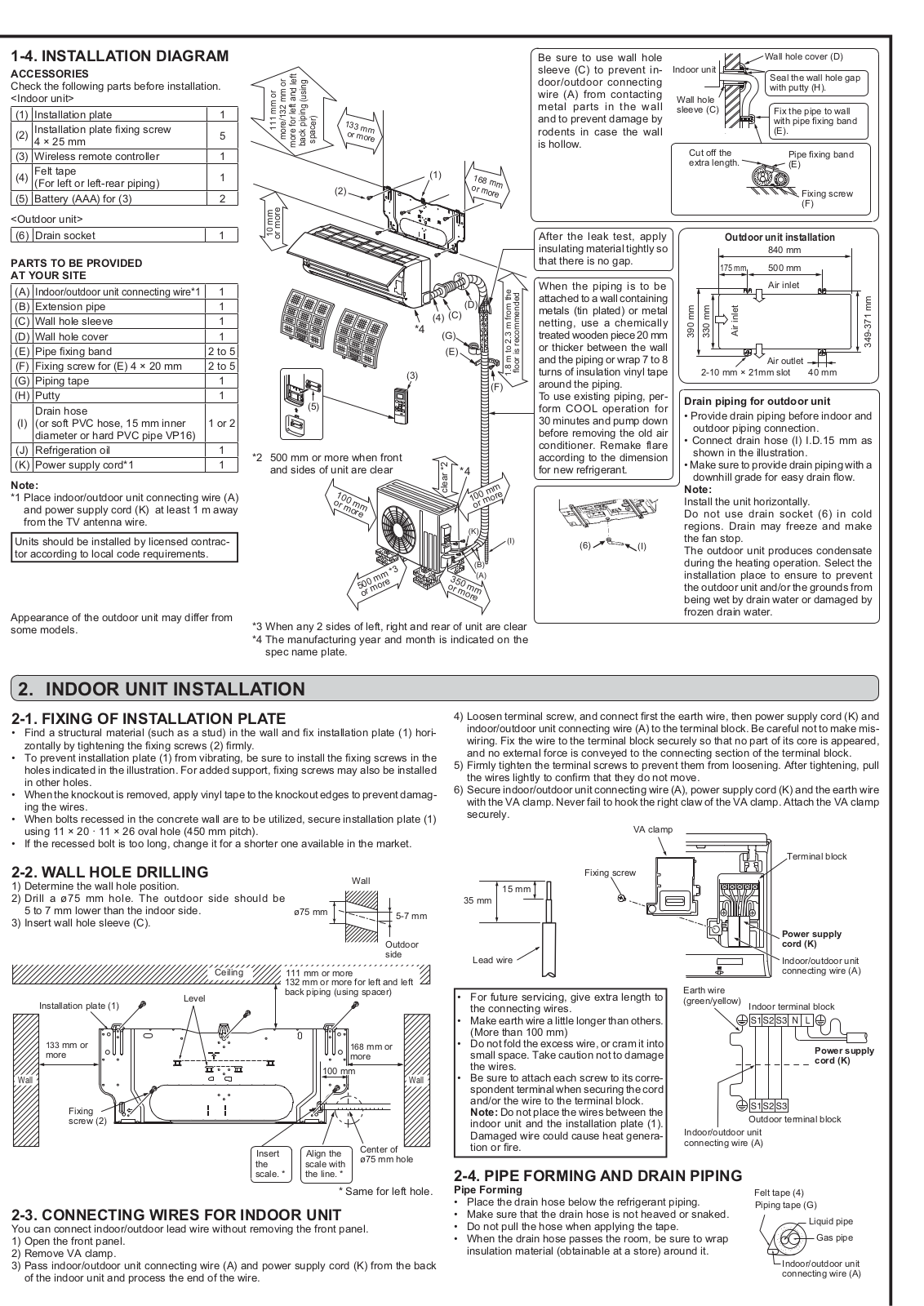
Mitsubishi Electric MSZ-DM71VA, MSZ-DM60VA, MUZ-DM71VA, MUZ-DM60VA Installation guide
...
Mitsubishi Electric Installation guide
Download
Specifications and Main Features
Frequently Asked Questions
User Manual
Download
Page 1
Page 2
Page 3
Page 4
Loading...
+
hidden pages
Unhide
You need points to download manuals.
1 point = 1 manual.
You can buy points or you can get point for every manual you upload.
Buy points
Upload your manuals