

Mitsubishi Electric Mr. Slim SEZ-KD09, Mr. Slim SEZ-KD12, Mr. Slim SEZ-KD15, Mr. Slim SEZ-KD18NA Operation Manual
Page 1
Air-Conditioners
SEZ-KD09,KD12,KD15,KD18NA
OPERATION MANUAL
For safe and correct use, please read this operation manual thoroughly before operating the air-conditioner unit.
FOR USER
English
MANUEL D’UTILISATION
Pour une utilisation correcte sans risques, veuillez lire le manuel d’utilisation en entier avant de vous servir du
climatiseur.
POUR L’UTILISATEUR
Français
KB79K741H01_cover.pm6 08.9.19, 3:17 PM1
Page 2
2
Contents
s Before installing the unit, make sure you read all the “Safety
Precautions”.
s The “Safety Precautions” provide very important points regard-
ing safety. Make sure you follow them.
s Please report to or take consent by the supply authority be-
fore connection to the system.
1. Safety Precautions
2. Parts Names
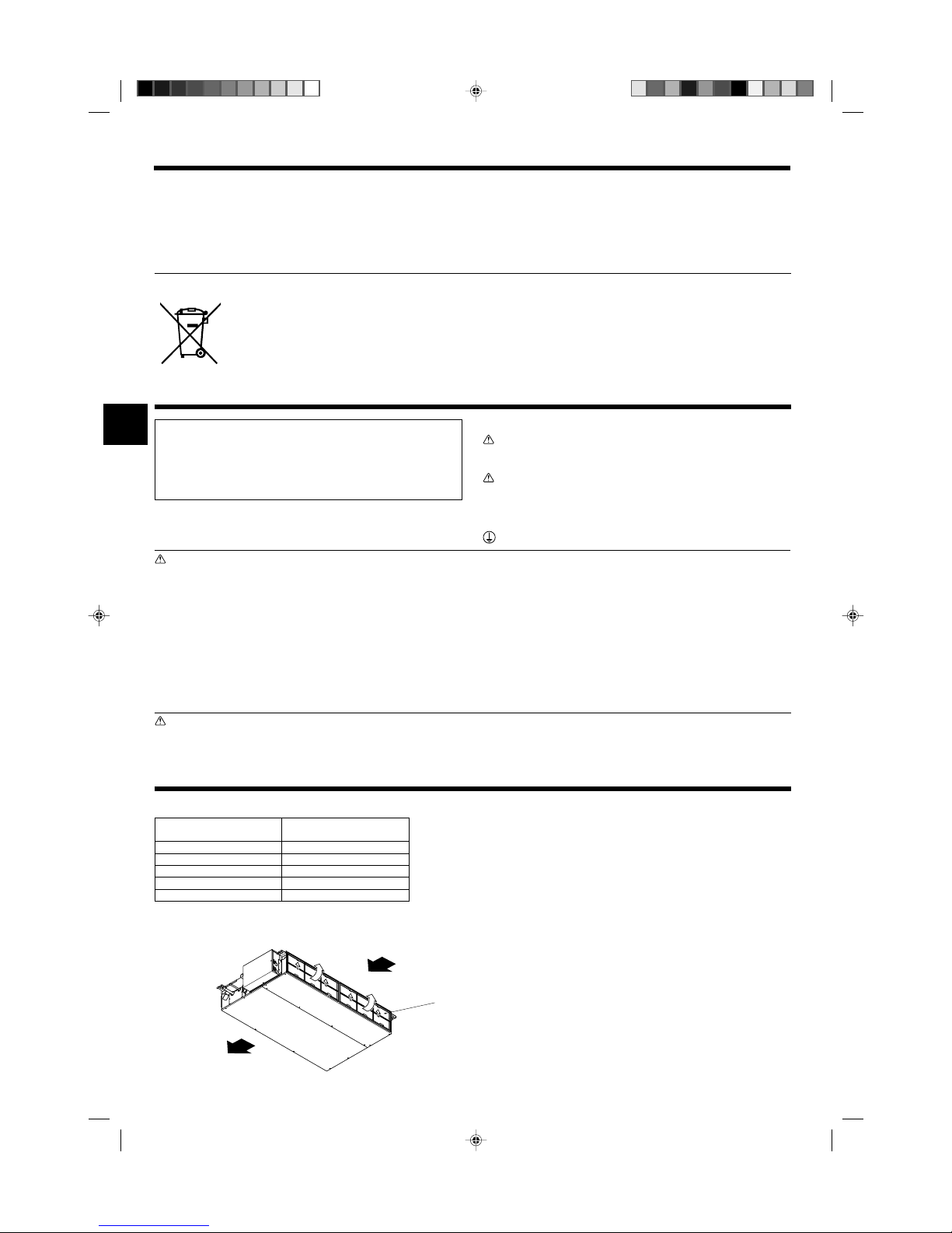
■ Indoor Unit
SEZ-KD·NA
Fan steps 3 steps
Vane –
Louver –
Filter Normal
Filter cleaning indication –
This symbol mark is for EU countries only.
This symbol mark is according to the directive 2002/96/EC Article 10 Information for users and Annex IV.
Your MITSUBISHI ELECTRIC product is designed and manufactured with high quality materials and components which can be
recycled and reused.
This symbol means that electrical and electronic equipment, at their end-of-life, should be disposed of separately from your household waste.
Please, dispose of this equipment at your local community waste collection/recycling center.
In the European Union there are separate collection systems for used electrical and electronic product.
Please, help us to conserve the environment we live in!
Symbols used in the text
Warning:
Describes precautions that should be observed to prevent danger of
injury or death to the user.
Caution:
Describes precautions that should be observed to prevent damage
to the unit.
Symbols used in the illustrations
: Indicates a part which must be grounded.
Warning:
• The unit must not be installed by the user. Ask the dealer or an
authorized company to install the unit. If the unit is installed improperly, water leakage, electric shock or fire may result.
• Do not stand on, or place any items on the unit.
• Do not splash water over the unit and do not touch the unit with
wet hands. An electric shock may result.
• Do not spray combustible gas close to the unit. Fire may result.
• Do not place a gas heater or any other open-flame appliance where
it will be exposed to the air discharged from the unit. Incomplete
combustion may result.
• Do not remove the front panel or the fan guard from the outdoor
unit when it is running.
• When you notice exceptionally abnormal noise or vibration, stop
operation, turn off the power switch, and contact your dealer.
• Never insert fingers, sticks etc. into the intakes or outlets.
• If you detect odd smells, stop using the unit, turn off the power
switch and consult your dealer. Otherwise, a breakdown, electric
shock or fire may result.
• This air conditioner is NOT intended for use by children or infirm
persons without supervision.
• Young children must be supervised to ensure that they do not play
with the air conditioner.
•
If the refrigeration gas blows out or leaks, stop the operation of the
air conditioner, thoroughly ventilate the room, and contact your dealer.
Caution:
• Do not use any sharp object to push the buttons, as this may damage the remote controller.
• Never block or cover the indoor or outdoor unit’s intakes or outlets.
Disposing of the unit
When you need to dispose of the unit, consult your dealer.
Note (Marking
for WEEE)
■ SEZ-KD·NA
Ceiling Concealed
1. Safety Precautions ................................................................ 2
2. Parts Names .......................................................................... 2
3. Screen Configuration............................................................. 4
4. Setting the Day of the Week and Time .................................. 4
5. Operation............................................................................... 5
6. Timer ..................................................................................... 6
7. Other Functions ..................................................................... 9
8. Function Selection ............................................................... 10
9. Care and Cleaning .............................................................. 14
10. Troubleshooting ................................................................. 15
11. Installation, relocation and inspection ............................... 16
12. Specifications .................................................................... 17
Air outlet
Air intake
Filter
KB79K741H01_en.pm6 08.10.7, 10:26 AM2
Page 3
3
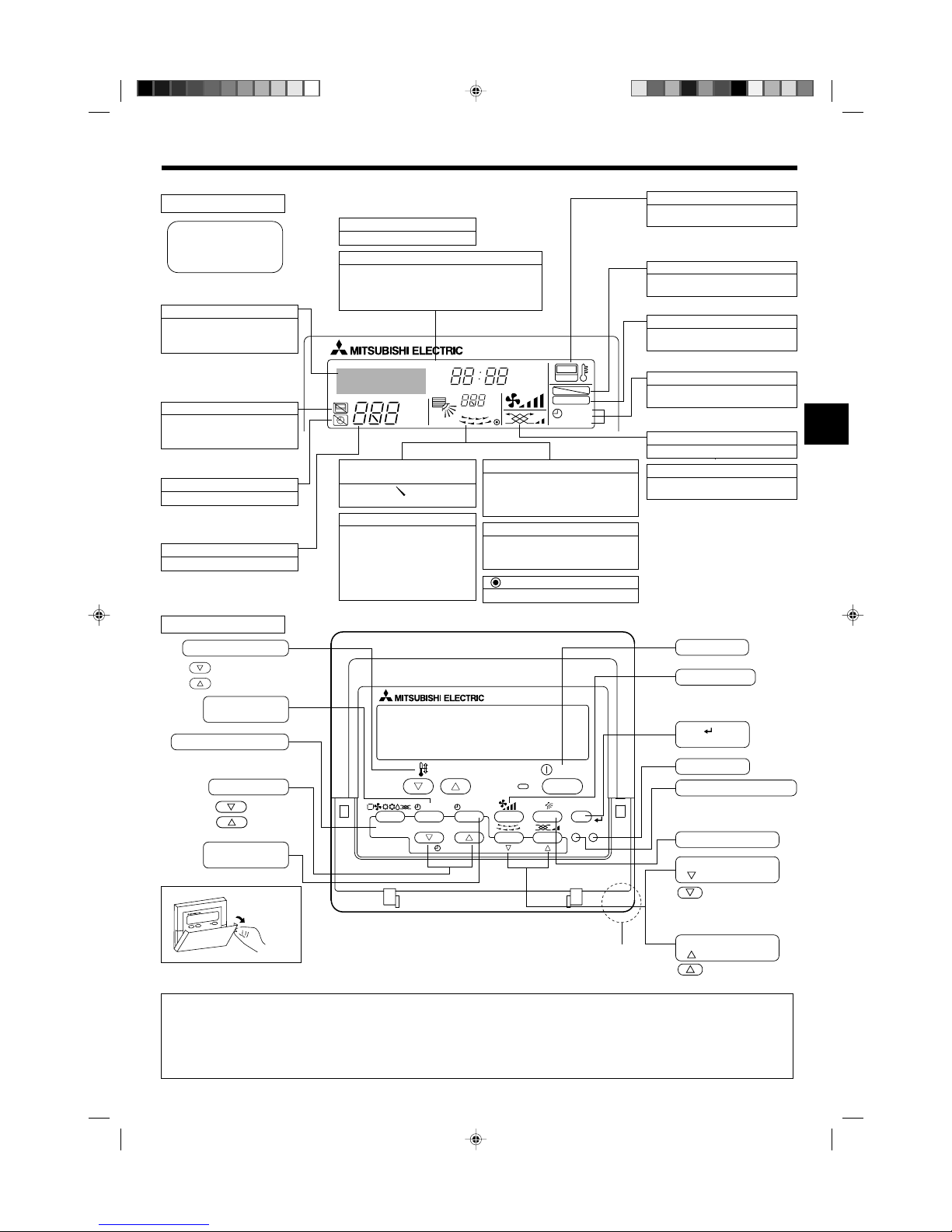
■ Wired Remote-Controller
Display Section
For information purposes, all parts
of the display are shown as lit.
During actual operation, only the
relevant items will be lit.
˚F˚C
˚F˚C
ERROR CODE
AFTER
TIMER
TIME SUN MON TUE WED THU FRI SAT
ON
OFF
Hr
AFTER
FILTER
FUNCTION
ONLY1Hr.
WEEKLY
SIMPLE
AUTO OFF
Identifies the current operation
Displays the operating mode, etc.
* Multilanguage display is sup-
ported.
“Centrally Controlled” indicator
Indicates that operation of the remote controller has been prohibited by a master controller.
“Timer is Off” indicator
Indicates that the timer is off.
Temperature Setting
Shows the target temperature.
Day-of-Week
Shows the current day of the week.
Time/Timer Display
Shows the current time (the 12 hour clock or the 24
hour clock ), unless the simple or Auto Off timer is set.
If the simple or Auto Off timer is set, shows the time
remaining.
“Sensor” indication
Displayed when the remote controller
sensor is used.
“Locked” indicator
Indicates that remote controller buttons have been locked.
“Clean The Filter” indicator
Comes on when it is time to clean the
filter.
Timer indicators
The indicator comes on if the corresponding timer is set.
Up/Down Air Direction indicator
The indicator shows the direction of the outcoming airflow.
“One Hour Only” indicator
Displayed if the airflow is set to
weak and downward during COOL
or DRY mode. (Operation varies
according to model.)
The indicator goes off after one
hour, at which time the airflow direction also changes.
Room Temperature display
Shows the room temperature. The room temperature display range is 46 °F [8 °C]–102 °F [39 °C].
The display flashes if the temperature is less than
46 °F [8 °C] or 102 °F [39 °C] or more.
Louver display
Indicates the action of the swing louver.
Does not appear if the louver is stationary.
(Power On indicator)
Indicates that the power is on.
Fan Speed indicator
Shows the selected fan speed.
Ventilation indicator
Appears when the unit is running in
Ventilation mode.
Operation Section
PAR-21MAA
ON/OFF
FILTER
CHECK
OPERATION
CLEAR
TEST
TEMP.
MENU
BACK DAY
MONITOR/SET
CLOCK
ON/OFF
Set Temperature buttons
Down
Up
Timer Menu button
(Monitor/Set button)
Mode button (Return button)
Set Time buttons
Back
Ahead
Timer On/Off button
(Set Day button)
Opening the
door.
ON/OFF button
Fan Speed button
Filter button
(<Enter> button)
Test Run button
Check button (Clear button)
Airflow Up/Down button
Louver button
(
Operation button)
To preceding operation
number.
Ventilation button
(
Operation button)
To next operation
number.
2. Parts Names
Built-in temperature sensor
Note:
● “PLEASE WAIT” message
This message is displayed for approximately 3 minutes when power is supplied to the indoor unit or when the unit is recovering from a power failure.
● “NOT AVAILABLE” message
This message is displayed if a button is pressed to operate a function that the indoor unit does not have.
If a single remote controller is used to simultaneously operate multiple indoor units that are different models, this message will not be displayed if
any of the indoor units is equipped with the function.
KB79K741H01_en.pm6 08.10.1, 3:35 PM3
Page 4
4
2. Parts Names
Note:
● The day and time will not appear if clock use has been disabled at the Function Selection of remote controller.
● After the power supply returns, the indoor unit does not operate for three
minutes. Above operation is normal.
● If the setting
11
11
1 or
22
22
2 is set, the 12 hour clock (AM/PM) will be displayed.
11
11
1CHANGE LANGUAGE setting = English [Refer to page 12]
22
22
2Temperature display setting =
°F [Refer to page 12]
If the settings above are not set, the 24 hour clock (rail road time/military
time) will be displayed.
Only “Set Day/Time”, “Standard Control Screens”, “Timer Monitor” and
“Timer Set UP” screens are applicable to the settings.
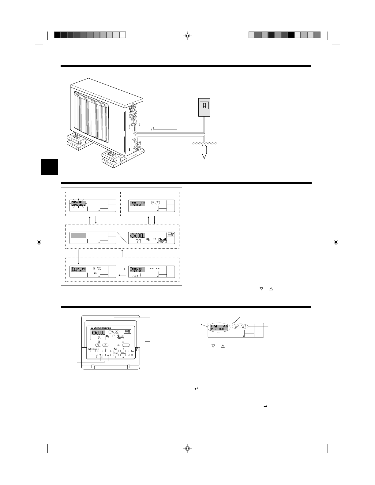
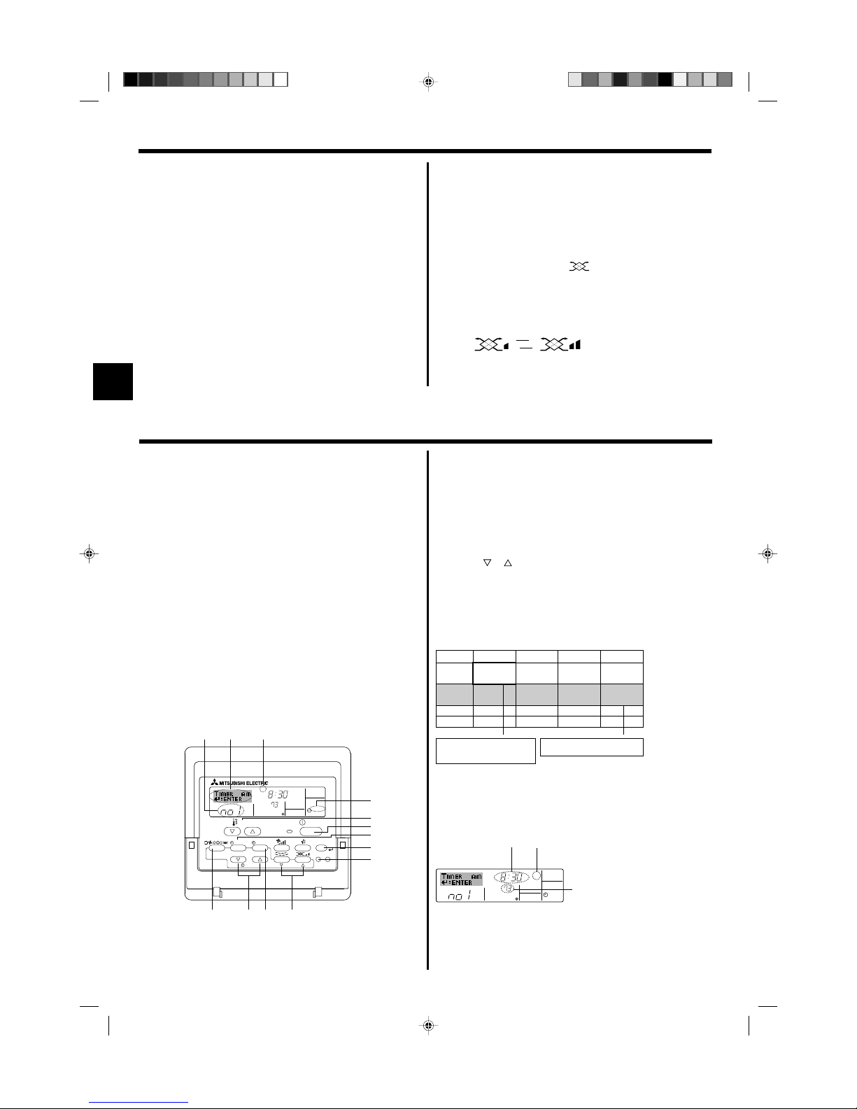
3. Screen Configuration
■ Outdoor unit
<Screen Types>
For details on setting the language for the remote controller display, refer
to Section 8: Function Selection.
The initial language setting is English.
● Function Selection of remote controller:
Set the functions and ranges available to the remote controller (timer functions, operating restrictions, etc.)
● Set Day/Time: Set the current day of the week or time.
● Standard Control Screens:
View and set the air conditioning system’s operating status
● Timer Monitor: View the currently set timer (weekly timer, sim-
ple timer, or Auto Off timer)
● Timer Setup: Set the operation of any of the timers (weekly
timer, simple timer, or Auto Off timer).
<How to change the screen>
A : Hold down both the Mode button and the Timer On/Off button for 2
seconds.
B : Press the Timer Menu button.
C : Press the Mode (Return) button.
D : Press either of the Set Time buttons ( or ).
˚F˚F
TIMER
MON
OFF
WEEKLY
SUN MON TUE WED THU FRI SAT
WEEKLY
˚F˚F
˚F
TIME SUN
Function Selection of remote controller
Set Day/Time
Standard Control Screens
OFF ON
Timer Monitor Timer Setup
ADC
BC
B
1. Press the or Set Time button A to show display 2.
2. Press the Timer On/Off (Set Day) button 9 to set the day.
*Each press advances the day shown at 3 : Sun → Mon → ... → Fri →
Sat.
3. Press the appropriate Set Time button A as necessary to set the time.
*As you hold the button down, the time (at 4) will increment first in
minute intervals, then in ten-minute intervals, and then in one-hour intervals.
4. After making the appropriate settings at Steps 2 and 3, press the Filter
button 4 to lock in the values.
Note:
● Your new entries at Steps 2 and 3 will be cancelled if you press the Mode
(Return) button
22
22
2 before pressing the Filter
button
44
44
4.
5. Press the Mode (Return) button 2 to complete the setting procedure.
This will return the display to the standard control screen, where 1 will
now show the newly set day and time.
4. Setting the Day of the Week and Time
Day of the Week &
Time display
˚F
˚F
TIME SUN
PAR-21MAA
ON/OFF
FILTER
CHECK
OPERATION
CLEAR
TEST
TEMP.
MENU
BACK DAY
MONITOR/SET
CLOCK
ON/OFF
2
4
9
1
A
Time Setting
TIME SUN
2
3
4
Day of the Week Setting
Power
Ground
Indoor-Outdoor
Connection wire
Refrigerant
Pipes
KB79K741H01_en.pm6 08.10.7, 9:33 AM4
Page 5

5
˚F
˚F
PAR-21MAA
ON/OFF
FILTER
CHECK
OPERATION
CLEAR
TEST
TEMP.
MENU
BACK DAY
MONITOR/SET
CLOCK
ON/OFF
2
7
2
3
3
8
6
4
5
8
7
1
1
5
6
5. Operation
5.1. Description of “AUTO RESTART FUNCTION”
• This unit is equipped with the auto restart function. When the main power is
turned on, the air conditioner will start operation automatically in the same
mode as set with the remote controller before the shutoff of main power.
• If the unit was set to off with the remote controller before the shutoff of
main power, it will remain stopped even after the main power is turned on.
• If the unit was in the TEST RUN before the shutoff of main power, it will
start operation, at main power on, in the same mode as set with the
remote controller before the TEST RUN.
Mode
Temperature setting
Fan speed
Remote Controller settings
Last operation mode
Last set temperature
Last set fan speed
5.2. Turning ON/OFF
<To Start Operation>
■ Press the ON/OFF button 1.
• The ON lamp 1 and the display area come on.
Note:
● When the unit is restarted, initial settings are as follows.
<To Stop Operation>
■ Press the ON/OFF button 1 again.
• The ON lamp 1 and the display area go dark.
Note:
Even if you press the ON/OFF button immediately after shutting down the operation is progress, the air conditioner will not start for about three minutes.
This is to prevent the internal components from being damaged.
5.3. Mode select
■ If the unit is off, press the ON/OFF button to turn it on.
• 1 The ON indicator should light up.
■ Press the operation mode ( ) button 2 and select the opera-
tion mode 2.
Cooling mode
Drying mode
Fan mode
Heating mode
Automatic (cooling/heating) mode
Ventillation mode
Only indicated on the following condition
Wired remote controller used
LOSSNAY connected
Information for multi system air conditioner (Outdoor
unit: MXZ series)
ss
ss
sMulti system air conditioner (Outdoor unit: MXZ series) can con-
nect two or more indoor units to one outdoor unit. According to the
capacity, two or more units can operate simultaneously.
• When you try to operate two or more indoor units with one outdoor unit
simultaneously, one for the cooling and the other for heating, the operation mode of the indoor unit that operates earlier is selected. The other
indoor units that will start the operation later cannot operate, and will
flash the operation state.
In this case, set all the indoor units to the same operation mode.
• There might be a case that the indoor unit, which is operating in
(AUTO) mode. It cannot change over to the operating mode (COOL ↔
HEAT) and goes to stand by mode.
• When indoor unit starts the operation while the outdoor unit is in defrost
mode, it takes a few minutes (max. about 15 minutes) to blow out the
warm air.
• In heating operation, though an indoor unit that is not operating may it
get warm or the sound of refrigerant flowing may be heard, it is not malfunctioning. That the refrigerant continuously flows into it.
Automatic operation
■ According to a set temperature, cooling operation starts if the room temperature is too hot and heating operation starts if the room temperature
is too cold.
■ During automatic operation, if the room temperature changes and remains 4 °F [2 °C] or more above the set temperature for 15 minutes, the
air conditioner switches to cooling mode. If the room temperature remains 4 °F [2 °C] or more below the set temperature for 15 minutes, the
air conditioner switches to heating mode.
■ Because the room temperature is automatically adjusted in order to
maintain a fixed effective temperature, cooling operation is performed a
few degrees warmer and heating operation is performed a few degrees
cooler than the set room temperature once the temperature is reached
(automatic energy-saving operation).
Cooling mode
15 minutes (switches
from heating to cooling)
Set temperature +4 °F [2 °C]
Set temperature
Set temperature -4 °F [2 °C]
15 minutes (switches
from cooling to heating )
5.4. Temperature setting
ss
ss
sTo decrease the room temperature:
Press button 3 to set the desired temperature.
The selected temperature is displayed 3.
• Each time you press the button, the temperature value decreases by 2 °F
[1 °C].
ss
ss
sTo increase the room temperature:
Press button 3 to set the desired temperature.
The selected temperature is displayed 3.
• Each time you press the button, the temperature value decreases by 2 °F
[1 °C].
• Available temperature ranges are as follows:
Cooling/Drying: 67 °F [19 °C] - 86 °F [30 °C]
Heating: 63 °F [17 °C] - 83 °F [28 °C]
Automatic: 67 °F [19 °C] - 83 °F [28 °C]
• The display flashes either 47 °F [8 °C] - 103 °F [39 °C] to inform you if
the room temperature is lower or higher than the displayed temperature.
5.5. Fan speed setting
■ Press 5 button to select a desired fan speed.
• Each time you press the button, available options change with the
display 5 on the remote controller, as shown below.
Fan speed
Remote controller display
Low Medium High Auto
3-stage
▼
( )
( )
( )
▼
▼
▼
s
Note:
Auto Mode is not recommended if this indoor unit is connected to a MXZ type
outdoor unit.
KB79K741H01_en.pm6 08.10.7, 9:33 AM5
Page 6
6
5. Operation
6.1. For Wired Remote-controller
This section explains how to set and use the timer. You can use Function
Selection of remote controller to select which of three types of timer to use:
1 Weekly timer, 2 Simple timer, or 3 Auto Off timer.
For information about how to set the Function Selection of remote controller, refer to section 8. [4]–3 (3).
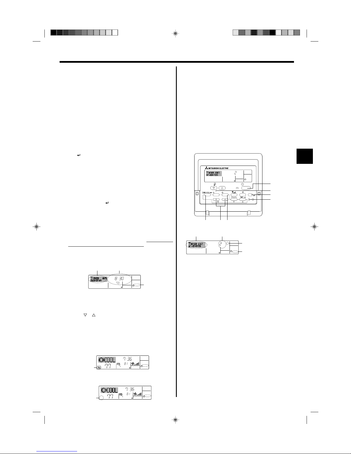
6.1.1. Weekly Timer
■ The weekly timer can be used to set up to eight operations for each day
of the week.
• Each operation may consist of any of the following: ON/OFF time
together with a temperature setting, or ON/OFF time only, or temperature setting only.
• When the current time reaches a time set at this timer, the air
conditioner carries out the action set by the timer.
■ Time setting resolution for this timer is 1 minute.
Note:
*1. Weekly Timer/Simple Timer/Auto Off Timer cannot be used at the same time.
*2. The weekly timer will not operate when any of the following conditions is in
effect.
The timer feature is off; the system is in an malfunction state; a test run is
in progress; the remote controller is undergoing self-check or remote controller check; the user is in the process of setting a function; the user is in
the process of setting the timer; the user is in the process of setting the
current day of the week or time; the system is under central control. (Specifically, the system will not carry out operations (unit on, unit off, or temperature setting) that are prohibited during these conditions.)
˚F
SUN
ON
WEEKLY
PAR-21MAA
ON/OFF
FILTER
CHECK
OPERATION
CLEAR
TEST
TEMP.
MENU
BACK DAY
MONITOR/SET
CLOCK
ON/OFF
2
42 3
A9 78
0
4
1
3
B
1
Operation No.
Day Setting
<How to Set the Weekly Timer>
1. Be sure that you are at a standard control screen, and that the weekly
timer indicator 1 is shown in the display.
2. Press the Timer Menu button B, so that the “Set Up” appears on the
screen (at 2). (Note that each press of the button toggles the display
between “Set Up” and “Monitor”.)
3. Press the Timer On/Off (Set Day) button 9 to set the day. Each press
advances the display at 3 to the next setting, in the following sequence:
“Sun Mon Tues Wed Thurs Fri Sat” → “Sun” → ... → “Fri” → “Sat” → “Sun
Mon Tues Wed Thurs Fri Sat”...
4. Press the or Operation button (7 or 8) as necessary to select the
appropriate operation number (1 to 8) 4.
* Your inputs at Steps 3 and 4 will select one of the cells from the matrix
illustrated below.
(The remote-controller display at left shows how the display would
appear when setting Operation 1 for Sunday to the values indicated
below.)
6. Timer
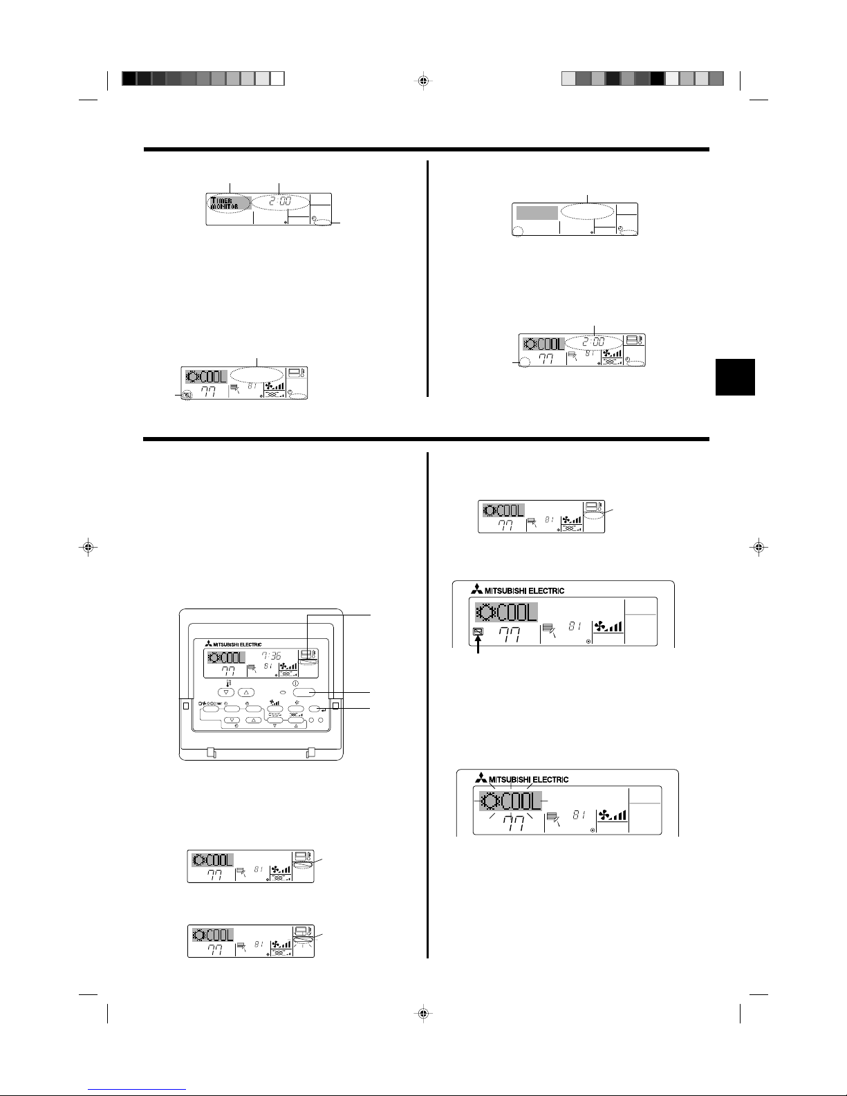
5.6. Ventilation
ss
ss
sFor LOSSNAY combination
5.6.1. For Wired Remote-controller
● To run the ventilator together with the indoor unit:
■ Press the ON/OFF button 1.
• The Vent indication appears on the screen (at 8). The ventilator will
now automatically operate whenever the indoor unit is running.
● To run the ventilator independently:
■ Press the Mode button 2 until appears on the display. This will
cause the ventilator to start.
● To change the ventilator force:
■ Press the Ventilation button 8 as necessary.
• Each press toggles the setting, as shown below.
Note:
By setting the day to “Sun Mon Tues Wed Thurs Fri Sat”, you can set the same
operation to be carried out at the same time every day.
(Example: Operation 2 above, which is the same for all days of the week.)
<Setting the Weekly Timer>
˚F
SUN
ON
WEEKLY
6
7
5
Shows the selected operation (ON or OFF)
* Does not appear if operation is not set.
Shows the temperature setting
* Does not appear if temperature is not
set.
Shows the time
setting
The display and the fan speed of the unit will differ in the following situations:
• When STAND BY and DEFROST are displayed.
• Just after the heating mode (while waiting to change to another mode).
• When the temperature of the room is higher than the temperature set-
ting of the unit operating in the heating mode.
• In the dry operation, the indoor fan automatically turns to low-speed
operation. Switching of fan speed is impossible.
• When the temperature of the heat exchanger is low in the heating mode
(e.g., immediately after heating operation starts).
Note:
● In the following cases, the actual fan speed generated by the unit will differ
from the speed shown the remote controller display.
1. While the display is showing “STAND BY” or “DEFROST”.
2. When the temperature of the heat exchanger is low in the heating mode.
(e.g. immediately after heating operation starts)
3. In HEAT mode, when room temperature is higher than the temperature
setting.
4. When the unit is in DRY mode.
▲
▲
Low High
Op No. Sunday Monday … Saturday
No. 1
No. 2
…
No. 8
• 8:30
• ON
• 73 °F [23 °C]
• 10:00
• OFF
• 10:00
• OFF
• 10:00
• OFF
• 10:00
• OFF
▲
Setup Matrix
<Operation 1 settings for Sunday>
Start the air conditioner at 8:30, with
the temperature set to 73 °F [23 °C].
▲
<Operation 2 settings for every day>
Turn off the air conditioner at 10:00.
KB79K741H01_en.pm6 08.10.1, 3:35 PM6
Page 7
7
6. Timer
5. Press the appropriate Set Time button A as necessary to set the
desired time (at 5).
* As you hold the button down, the time first increments in minute inter-
vals, then in ten-minute intervals, and then in one-hour intervals.
6. Press the ON/OFF button 1 to select the desired operation (ON or
OFF), at 6.
* Each press changes the next setting, in the following sequence:
No display (no setting) → “ON” → “OFF”
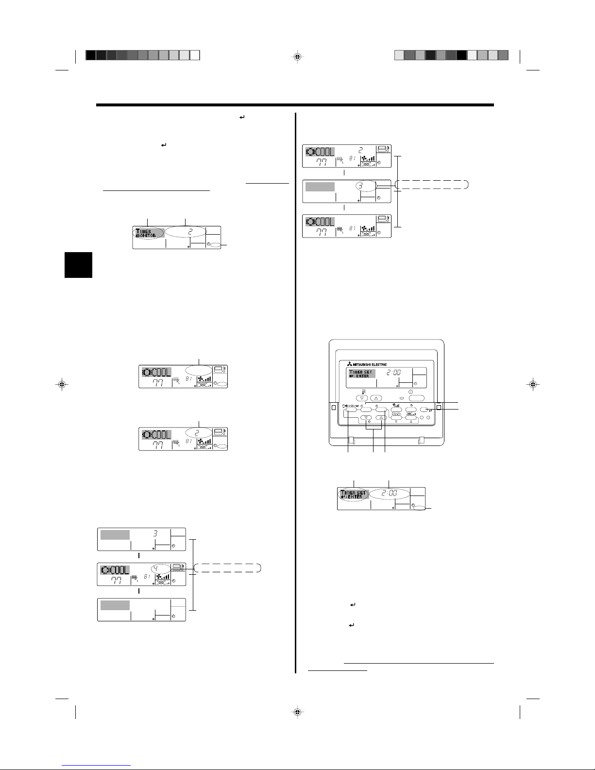
6.1.2. Simple Timer
■ You can set the simple timer in any of three ways.
• Start time only:
The air conditioner starts when the set time has elapsed.
• Stop time only:
The air conditioner stops when the set time has elapsed.
• Start & stop times:
The air conditioner starts and stops at the respective elapsed times.
■ The simple timer (start and stop) can be set only once within a 72-hour
period.
The time setting is made in hour increments.
Note:
*1. Weekly Timer/Simple Timer/Auto Off Timer cannot be used at the same time.
*2. The simple timer will not operate when any of the following conditions is in
effect.
The timer is off; the system is in malfunction state; a test run is in progress;
the remote controller is undergoing self-check or remote controller check;
the user is in the process of selecting a function; the user is in the process
of setting the timer; the system is under central control. (Under these conditions, On/Off operation is prohibited.)
ONHr
AFTER
SIMPLE
PAR-21MAA
ON/OFF
FILTER
CHECK
OPERATION
CLEAR
TEST
TEMP.
MENU
BACK DAY
MONITOR/SET
CLOCK
ON/OFF
2A9
0
4
1
B
Action (On or Off)
* “— —” is displayed if there is no
setting.
<How to Set the Simple Timer>
1. Be sure that you are at a standard control screen, and that the simple
timer indicator is visible in the display (at 1).
When something other than the Simple Timer is displayed, set it to
SIMPLE TIMER using the function selection of remote controller (see
8.[4]–3 (3)) timer function setting.
2. Press the Timer Menu button B, so that the “Set Up” appears on the
screen (at 2). (Note that each press of the button toggles the display
between “Set Up” and “Monitor”.)
3. Press the ON/OFF button 1 to display the current ON or OFF simple
timer setting. Press the button once to display the time remaining to ON,
and then again to display the time remaining to OFF. (The ON/OFF
indication appears at 3).
•“ON” timer:
The air conditioner will start operation when the specified number of
hours has elapsed.
•“OFF” timer:
The air conditioner will stop operation when the specified number of
hours has elapsed.
4. With “ON” or “OFF” showing at 3: Press the appropriate Set Time button
A as necessary to set the hours to ON (if “ON” is displayed) or the hours
to OFF (if “OFF” is displayed) at 4.
• Available Range: 1 to 72 hours
5. To set both the ON and OFF times, repeat Steps 3 and 4.
* Note that ON and OFF times cannot be set to the same value.
6. To clear the current ON or OFF setting: Display the ON or OFF setting
(see step 3) and then press the Check (Clear) button 0 so that the time
setting clears to “—” at 4. (If you want to use only an ON setting or only
an OFF setting, be sure that the setting you do not wish to use is shown
as “—”.)
˚F
˚F
TIME SUN
WEEKLY
0
˚F
˚F
TIME SUN
WEEKLY
0
7. Press the appropriate Set Temperature button 3 to set the desired
temperature (at 7).
* Each press changes the setting, in the following sequence: No
display (no setting) ⇔ 76 °F [24 °C] ⇔ 78 °F [25 °C] ⇔ ... ⇔
84 °F [29 °C] ⇔ 86 ° F [30 °C] ⇔ 54 °F [12 °C] ⇔ ... ⇔ 73 °F
[23 °C] ⇔ No display.
(Available range: The range for the setting is 54 °F [12 °C] to 86 °F
[30 °C]. The actual range over which the temperature can be controlled, however, will vary according to the type of the connected
unit.)
8. After making the appropriate settings at Steps 5, 6 and 7, press the
Filter button 4 to lock in the values.
To clear the currently set values for the selected operation, press and
quickly release the Check (Clear) button 0 once.
* The displayed time setting will change to “—:—”, and the On/Off
and temperature settings will all disappear.
(To clear all weekly timer settings at once, hold down the Check
(Clear) button 0 for two seconds or more. The display will begin
flashing, indicating that all settings have been cleared.)
Note:
Your new entries will be cancelled if you press the Mode (Return) button 2
before pressing the Filter
button 4.
If you have set two or more different operations for exactly the same time,
only the operation with the highest Operation No. will be carried out.
9. Repeat Steps 3 to 8 as necessary to fill as many of the available cells
as you wish.
10.Press the mode (Return) button 2 to return to the standard control
screen and complete the setting procedure.
11.To activate the timer, press the Timer On/Off button 9, so that the
“Timer Off” indication disappears from the screen. Be sure that the
“Timer Off” indication is no longer displayed.
* If there are no timer settings, the “Timer Off” indication will flash on
the screen.
<How to View the Weekly Timer Settings>
1.
Be sure that the weekly timer indicator is visible on the screen (at 1).
2. Press the Timer Menu button B so that “Monitor” is indicated on the
screen (at 8).
3. Press the Timer On/Off (Set Day) button 9 as necessary to select
the day you wish to view.
4. Press the or Operation button (7 or 8) as necessary to change
the timer operation shown on the display (at 9).
* Each press will advance to the next timer operation, in order of
time setting.
5. To close the monitor and return to the standard control screen, press
the Mode (Return) button 2.
<To Turn Off the Weekly Timer>
Press the Timer On/Off button 9 so that “Timer Off” appears at 0.
Timer Settings
˚F
TIMER
SUN
ON
OFF
WEEKLY
1
9
8
ONHr
AFTER
SIMPLE
4
1
3
2
Timer Setting
<To Turn On the Weekly Timer>
Press the Timer On/Off button 9 so that the “Timer Off” indication (at 0)
goes dark.
KB79K741H01_en.pm6 08.10.1, 3:35 PM7
Page 8
8
6. Timer
7. After completing steps 3 to 6 above, press the Filter button 4 to lock
in the value.
Note:
Your new settings will be cancelled if you press the Mode (Return) button 2
before pressing the Filter
button 4.
8. Press the Mode (Return) button 2 to return to the standard control
screen.
9. Press the Timer On/Off button 9 to start the timer countdown. When the
timer is running, the timer value is visible on the display. Be sure that the
timer value is visible and appropriate.
<Viewing the Current Simple Timer Settings>
TIMER ON
OFFHrAFTER
SIMPLE
1
6
5
1. Be sure that the simple timer indicator is visible on the screen (at 1).
2. Press the Timer Menu button B, so that the “Monitor” appears on the
screen (at 5).
• If the ON or OFF simple timer is running, the current timer value will
appear at 6.
• If ON and OFF values have both been set, the two values appear
alternately.
3. Press the Mode (Return) button 2 to close the monitor display and return
to the standard control screen.
<To Turn Off the Simple Timer...>
Press the Timer On/Off button 9 so that the timer setting no longer appears on the screen (at 7).
Timer Setting
˚F
˚F
SIMPLE
7
˚F
˚F
ONHr
AFTER
SIMPLE
7
<To Turn On the Simple Timer...>
Press the Timer On/Off button 9 so that the timer setting becomes visible
at 7.
Examples
If ON and OFF times have both been set at the simple timer, operation and
display are as indicated below.
Example 1:
Start the timer, with ON time set sooner than OFF time
ON Setting: 3 hours
OFF Setting: 7 hours
ONHr
AFTER
SIMPLE
˚F
˚F
OFFHrAFTER
SIMPLE
SIMPLE
˚F
˚F
OFFHrAFTER
SIMPLE
ONHr
AFTER
SIMPLE
▲
▲
▲
At 3 hours after timer start
Display changes to show the timer’s OFF setting (hours remaining to OFF).
The time displayed is OFF setting (7 hours) –
ON setting (3 hours) = 4 hours.
At Timer Start
Display shows the timer’s ON setting (hours
remaining to ON).
At 7 hours after timer start
The air conditioner goes off, and will remain off
until someone restarts it.
˚F
˚F
SIMPLE
▲
At 2 hours after timer start
Display changes to show the timer’s ON setting
(hours remaining to ON).
The time displayed is ON setting (5 hours) –
OFF setting (2 hours) = 3 hours.
At Timer Start
Display shows the timer’s OFF setting (hours
remaining to OFF).
At 5 hours after timer start
The air conditioner comes on, and will continue
to run until someone turns it off.
6.1.3. Auto Off Timer
■ This timer begins countdown when the air conditioner starts, and shuts
the air conditioner off when the set time has elapsed.
■ Available settings run from 30 minutes to 4 hours, in 30-minute intervals.
Note:
*1. Weekly Timer/Simple Timer/Auto Off Timer cannot be used at the same time.
*2. The Auto Off timer will not operate when any of the following conditions is
in effect.
The timer is off; the system is in malfunction state; a test run is in progress;
the remote controller is undergoing self-check or remote controller check;
the user is in the process of selecting a function; the user is in the process
of setting the timer; the system is under central control. (Under these conditions, On/Off operation is prohibited.)
AFTER OFF
AUTO OFF
PAR-21MAA
ON/OFF
FILTER
CHECK
OPERATION
CLEAR
TEST
TEMP.
MENU
BACK DAY
MONITOR/SET
CLOCK
ON/OFF
2A9
4
B
AFTER OFF
AUTO OFF
3
1
2
Timer Setting
<How to Set the Auto Off Timer>
1. Be sure that you are at a standard control screen, and that the Auto Off
timer indicator is visible in the display (at 1).
When something other than the Auto Off Timer is displayed, set it to
AUTO OFF TIMER using the function selection of remote controller (see
8.[4]–3 (3)) timer function setting.
2. Hold down the Timer Menu button B for 3 seconds, so that the “Set Up”
appears on the screen (at 2).
(Note that each press of the button toggles the display between “Set Up”
and “Monitor”.)
3. Press the appropriate Set Time button A as necessary to set the OFF
time (at 3).
4. Press the Filter button 4 to lock in the setting.
Note:
Your entry will be cancelled if you press the Mode (Return) button 2 before
pressing the Filter
button 4.
5. Press the Mode (Return) button 2 to complete the setting procedure and
return to the standard control screen.
6. If the air conditioner is already running, the timer starts countdown
immediately. Be sure to check that the timer setting appears cor-
rectly on the display.
Example 2:
Start the timer, with OFF time is sooner than ON time
ON Setting: 5 hours
OFF Setting: 2 hours
KB79K741H01_en.pm6 08.10.1, 3:35 PM8
Page 9
9
6. Timer
<Checking the Current Auto Off Timer Setting>
1. Be sure that the “Auto Off” is visible on the screen (at 1).
2. Hold down the Timer Menu button B for 3 seconds, so that “Monitor” is
indicated on the screen (at 4).
• The timer remaining to shutdown appears at 5.
3. To close the monitor and return to the standard control screen, press the
Mode (Return) button 2.
<To Turn Off the Auto Off Timer...>
● Hold down the Timer On/Off button 9 for 3 seconds, so that “Timer Off”
appears (at 6) and the timer value (at 7) disappears.
˚F
˚F
AUTO OFF
6
7
AUTO OFF
7
˚F
˚F
AFTER OFF
AUTO OFF
6
7
<To Turn On the Auto Off Timer...>
● Hold down the Timer On/Off button 9 for 3 seconds. The “Timer Off”
indication disappears (at 6), and the timer setting comes on the display
(at 7).
● Alternatively, turn on the air conditioner. The timer value will appear at 7.
AFTER
TIMER
OFF
AUTO OFF
5
1
4
Timer Setting
● Alternatively, turn off the air conditioner itself. The timer value (at 7) will
disappear from the screen.
7. Other Functions
˚F
˚F
TIME SUN
FUNCTION
PAR-21MAA
ON/OFF
FILTER
CHECK
OPERATION
CLEAR
TEST
TEMP.
MENU
BACK DAY
MONITOR/SET
CLOCK
ON/OFF
4
1
1
Lock Indicator
7.1. Locking the Remote Controller Buttons (Operation
function limit controller)
■ If you wish, you can lock the remote controller buttons. You can use the
Function Selection of remote controller to select which type of lock to use.
(For information about selecting the lock type, see section 8, item [4]–2
(1)).
Specifically, you can use either of the following two lock types.
1Lock All Buttons:
Locks all of the buttons on the remote controller.
2Lock All Except ON/OFF:
Locks all buttons other than the ON/OFF button.
Note:
The “Locked” indicator appears on the screen to indicate that buttons are currently locked.
<How to Lock the Buttons>
1. While holding down the Filter button 4, press and hold down the ON/OFF
button 1 for 2 seconds. The “Locked” indication appears on the screen
(at 1), indicating that the lock is now engaged.
* If locking has been disabled in Function Selection of remote controller,
the screen will display the “Not Available” message when you press the
buttons as described above.
˚F
˚F
FUNCTION
1
˚F
˚F
FUNCTION
1
˚F
˚F
1
• If you press a locked button, the “Locked” indication (at 1) will blink
on the display.
<How to Unlock the Buttons>
1. While holding down the Filter button 4, press and hold down the ON/OFF
button 1 for 2 seconds—so that the “Locked” indication disappears from
the screen (at 1).
ON/OFF
TEMP.
˚F
˚F
ON/OFF
TEMP.
˚F
˚F
7.2. Other indications
7.2.1. Centrally Controlled
■ When flashes continuously
Displayed when another indoor unit connected to the outdoor unit is
already operating in a different operation mode.
Match with the operation mode of the other indoor unit.
■ When mode switched after display flashes
Displayed when operation mode is restricted for each season by central
controller, etc.
Use another operation mode.
● Displayed when operation is controlled by central controller, etc.
Restricted operations are shown below.
• ON/OFF (including timer operation)
• Operation mode
• Set temperature
Note:
May also be individually restricted.
7.2.2. Flashing Mode Indicator
KB79K741H01_en.pm6 08.10.1, 3:36 PM9
Page 10
10
7. Other Functions
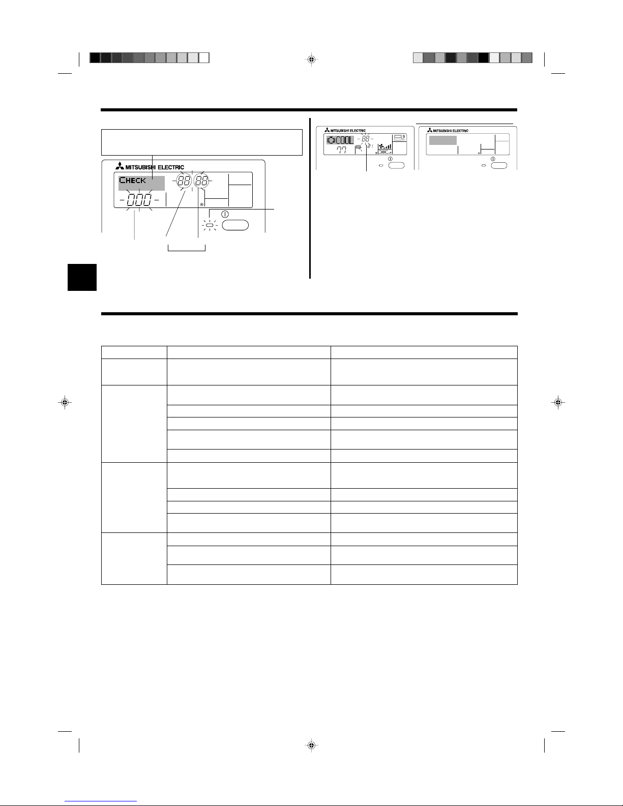
ON/OFF
ERROR CODE
If you have entered contact number to be called in the event of a problem, the screen displays this number. (You can set this up under Function Selection of remote controller. For information, refer to section 8.)
Indoor Unit’s
Refrigerant
Address
Error Code
Indoor Unit No.
Alternating
Display
ON/OFF
˚F
˚F
ERROR CODE
ON/OFF
CALL:XXXX
XXX:XXX
Error Code
When the Check button is pressed:
ON lamp
(Flashing)
7.2.3. Error Codes indication
● If the ON lamp and error code are both flashing: This means that the air
conditioner is out of order and operation has been stopped (and cannot
resume). Take note of the indicated unit number and error code, then
switch off the power to the air conditioner and call your dealer or servicer.
● If only the error code is flashing (while the ON lamp remains lit): Operation is continuing, but there may be a problem with the system. In this
case, you should note down the error code and then call your dealer or
servicer for advice.
* If you have entered contact number to be called in the event of a
problem, push the Check button to display it on the screen. (You can
set this up under Function Selection of remote controller. For information, refer to section 8.)
8. Function Selection
Function selection of remote controller
The setting of the following remote controller functions can be changed using the remote controller function selection mode. Change the setting when
needed.
Item 1
1. Change Language
(“CHANGE
LANGUAGE”)
2. Function limit
(“FUNCTION
SELECTION”)
3. Mode selection
(“MODE SELECTION”)
4. Display change
(“DISP MODE
SETTING”)
Item 2
Language setting to display
(1) Operation function limit setting (operation lock) (“LOCKING
FUNCTION”)
(2) Use of automatic mode setting (“SELECT AUTO MODE”)
(3) Temperature range limit setting (“LIMIT TEMP FUNCTION”)
(4) Use of automatic filter elevation panel up/down operation
mode setting
(5) Use of fixed airflow direction mode setting
(1) Remote controller main/sub setting (“CONTROLLER MAIN/
SUB”)
(2) Use of clock setting (“CLOCK”)
(3) Timer function setting (“WEEKLY TIMER”)
(4) Contact number setting for error situation (“CALL.”)
(1) Temperature display °C/°F setting (“TEMP MODE °C/°F”)
(2) Suction air temperature display setting (“ROOM TEMP DISP
SELECT”)
(3) Automatic cooling/heating display setting (“AUTO MODE
DISP C/H”)
Item 3 (Setting content)
• Display in multiple languages is possible
• Setting the range of operation limit (operation lock)
• Setting the use or non-use of “automatic” operation mode
• Setting the temperature adjustable range (maximum, minimum)
(For this model, this function is not available.)
(For this model, this function is not available.)
• Selecting main or sub remote controller
* When two remote controllers are connected to one group, one controller
must be set to sub.
• Setting the use or non-use of clock function
• Setting the timer type
• Contact number display in case of error
• Setting the telephone number
• Setting the temperature unit (°F or °C) to display
• Setting the use or non-use of the display of indoor (suction) air tempera-
ture
• Setting the use or non-use of the display of “Cooling” or “Heating” display
during operation with automatic mode
KB79K741H01_en.pm6 08.10.1, 3:36 PM10
Page 11
11
8. Function Selection
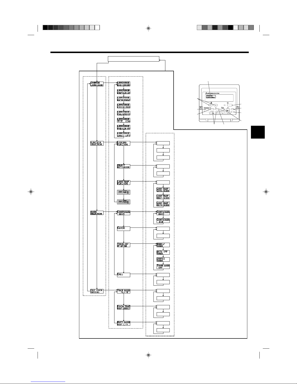
[Function selection flowchart]
Setting language (English)
OFF
on1
on2
OFF
ON
OFF
ON
OFF
OFF
CALL-
ON
OFF
ON
OFF
°C
°F
PAR-21MAA
ON/OFF
FILTER
CHECK
OPERATION
CLEAR
TEST
TEMP.
MENU
BACK DAY
MONITOR/SET
CLOCK
ON/OFF
F
E
G
C
D
H
B
A
I
G
G
G
G
G
G
E
E
G
G
G
G
G
E
G
E
G
G
G
G
G
G
D
D
D
D
D
D
D
D
D
D
D
D
D
D
D
D
D
D
D
D
D
D
D
D
D
D
D
D
D
D
English
Germany
Spanish
Russian
Italy
Chinese
French
Japanese
*
*
Hold down the E button and press the D button for 2 seconds.
Hold down the E button and press the D button for 2 seconds.
Remote controller function selection mode
E Press the operation mode button.
G Press the TIMER MENU button.
D Press the TIMER ON/OFF button.
Item1 Item2
Dot display
Item3
Room air temperature is not displayed.
One of “Automatic cooling” and “Automatic heating” is displayed
under the automatic mode is running. (Initial setting value)
Only “Automatic” is displayed under the automatic mode.
Normal display
(Display when the air condition is not running)
Change
Language
Function
selection
Mode
selection
Display
mode setting
Operation lock setting is not used.
(Initial setting value)
Operation lock setting is except On/Off button.
Operation lock setting is All buttons.
The automatic mode is displayed when the operation mode is
selected. (Initial setting value)
The automatic mode is not displayed when the operation mode
is selected.
The temperature range limit is not active. (Initial setting value)
The temperature range can be changed on cooling/dry mode.
The temperature range can be changed on heating mode.
The temperature range can be changed on automatic mode.
The remote controller will be the main controller. (Initial setting value)
The remote controller will be the sub controller.
The clock function can be used. (Initial setting value)
The clock function can not be used.
Weekly timer can be used. (Initial setting value)
Auto off timer can be used.
Simple timer can be used.
Timer mode can not be used.
The set contact numbers are not displayed in case of error.
(Initial setting value)
The set contact numbers are displayed in case of error.
The temperature unit °C is used. (Initial setting value)
The temperature unit °F is used.
Room air temperature is displayed. (Initial setting value)
*) For this model, this function is not available.
KB79K741H01_en.pm6 08.10.1, 3:36 PM11
Page 12

12
8. Function Selection
[Detailed setting]
[4]–1. CHANGE LANGUAGE setting
The language that appears on the dot display can be selected.
• Press the [ MENU] button G to change the language.
1 English (GB), 2 German (D), 3 Spanish (E), 4 Russian (RU),
5 Italian (I), 6 Chinese (CH), 7 French (F), 8 Japanese (JP)
Refer to the dot display table.
[4]–2. Function limit
(1) Operation function limit setting (operation lock)
• To switch the setting, press the [ ON/OFF] button D.
1 no1 : Operation lock setting is made on all buttons other than the
[ ON/OFF] button.
2 no2: Operation lock setting is made on all buttons.
3 OFF (Initial setting value): Operation lock setting is not made.
* To make the operation lock setting valid on the normal screen, it is
necessary to press buttons (Press and hold down the [FILTER] and
[ ON/OFF] buttons at the same time for two seconds.) on the
normal screen after the above setting is made.
(2) Use of automatic mode setting
When the remote controller is connected to the unit that has automatic
operation mode, the following settings can be made.
• To switch the setting, press the [ ON/OFF] button D.
1 ON (Initial setting value):
The automatic mode is displayed when the operation mode is
selected.
2 OFF:
The automatic mode is not displayed when the operation mode
is selected.
(3) Temperature range limit setting
After this setting is made, the temperature can be changed within the
set range.
• To switch the setting, press the [ ON/OFF] button D.
1 LIMIT TEMP COOL MODE:
The temperature range can be changed on cooling/dry mode.
2 LIMIT TEMP HEAT MODE:
The temperature range can be changed on heating mode.
3 LIMIT TEMP AUTO MODE:
The temperature range can be changed on automatic mode.
4 OFF (initial setting): The temperature range limit is not active.
* When the setting, other than OFF, is made, the temperature range
limit setting on cooling, heating and automatic mode is made at the
same time. However, the range cannot be limited when the set
temperature range has not changed.
• To increase or decrease the temperature, press the [ TEMP. ( )
or ( )] button F.
• To switch the upper limit setting and the lower limit setting, press the
[ ] button H. The selected setting will flash and the temperature
can be set.
• Settable range
Cooling/Dry mode:
Lower limit: 67 °F [19 °C] ~ 86 °F [30 °C]
Upper limit: 86 °F [30 °C] ~ 67 °F [19 °C]
Heating mode:
Lower limit: 63 °F [17 °C] ~ 83 °F [28 °C]
Upper limit: 83 °F [28 °C] ~ 63 °F [17 °C]
Automatic mode:
Lower limit: 67 °F [19 °C] ~ 83 °F [28 °C]
Upper limit: 83 °F [28 °C] ~ 67 °F [19 °C]
* The settable range varies depending on the unit to connect (Mr.
Slim units, CITY MULTI units, and intermediate temperature units)
(4) Use of automatic filter elevation panel up/down operation mode set-
ting
For this model, this function is not available.
(5) Use of fixed airflow direction mode setting
For this model, this function is not available.
[4]–3. Mode selection setting
(1) Remote controller main/sub setting
• To switch the setting, press the [ ON/OFF] button D.
1 Main: The controller will be the main controller.
2 Sub: The controller will be the sub controller.
(2) Use of clock setting
• To switch the setting, press the [ ON/OFF] button D.
1 ON: The clock function can be used.
2 OFF: The clock function cannot be used.
(3) Timer function setting
• To switch the setting, press the [ ON/OFF] button D (Choose one
of the followings.).
1 WEEKLY TIMER (initial setting value):
The weekly timer can be used.
2 AUTO OFF TIMER:
The auto off timer can be used.
3 SIMPLE TIMER:
The simple timer can be used.
4 TIMER MODE OFF:
The timer mode cannot be used.
* When the use of clock setting is OFF, the “WEEKLY TIMER” cannot
be used.
(4) Contact number setting for error situation
• To switch the setting, press the [ ON/OFF] button D.
1 CALL OFF:
The set contact numbers are not displayed in case of error.
2 CALL **** *** ****:
The set contact numbers are displayed in case of error.
CALL_:
The contact number can be set when the display is as shown on
the left.
• Setting the contact numbers
To set the contact numbers, follow the following procedures.
Move the flashing cursor to set numbers. Press the [ TEMP.
( ) and ( )] button F to move the cursor to the right (left). Press
the [ CLOCK ( ) and ( )] button C to set the numbers.
[4]–4. Display change setting
(1) Temperature display °C/°F setting
• To switch the setting, press the [ ON/OFF] button D.
1 °C: The temperature unit °C is used.
2 °F: The temperature unit °F is used.
(2) Suction air temperature display setting
• To switch the setting, press the [ ON/OFF] button D.
1 ON: The suction air temperature is displayed.
2 OFF: The suction air temperature is not displayed.
(3) Automatic cooling/heating display setting
• To switch the setting, press the [ ON/OFF] button D.
1 ON:
One of “Automatic cooling” and “Automatic heating” is displayed
under the automatic mode is running.
2 OFF:
Only “Automatic” is displayed under the automatic mode.
KB79K741H01_en.pm6 08.10.1, 3:36 PM12
Page 13

13
8. Function Selection
[Dot display table]
Waiting for start-up
Operation mode Cool
Dry
Heat
Auto
Auto (Cool)
Auto (Heat)
Fan
Ventilation
Stand by
(Hot adjust)
Defrost
Set temperature
Fan speed
Not available
Check (Error)
Test run
Self check
Unit function selection
Setting of ventilation
Selecting language
English Germany Spanish Russian Italy Chinese French Japanese
CHANGE LANGUAGE
Function selection
Operation function limit setting
Use of automatic mode setting
Temperature range limit setting
Use of automatic filter elevation panel
up/down operation mode setting
Use of fixed airflow direction mode
setting
Limit temperature cooling/day
mode
Limit temperature heating mode
Limit temperature auto mode
Mode selection
Remote controller setting MAIN
Remote controller setting SUB
Use of clock setting
Setting the day of the week and
time
Timer set
Timer monitor
Weekly timer
Timer mode off
Auto off timer
Simple timer
Selecting language
English Germany Spanish Russian Italy Chinese French Japanese
KB79K741H01_en.pm6 08.10.1, 3:36 PM13
Page 14

14
ON/OFF
TEMP.
˚F
˚F
FILTER
■ Indicates that the filter needs cleaning.
Clean the filter.
■ When resetting “FILTER” display
When the [FILTER] button is pressed two times successively after
cleaning the filter, the display goes off and is reset.
Note:
● When two or more different types of indoor unit are controlled, the cleaning
period differs with the type of filter. When the master unit cleaning period
arrives, “FILTER” is displayed. When the filter display goes off, the cumulative time is reset.
● “FILTER” indicates the cleaning period when the air conditioner was used
under general indoor air conditions by criteria time. Since the degree of dirtiness depends on the environmental conditions, clean the filter accordingly.
● The filter cleaning period cumulative time differs with the model.
● This indication is not available for wireless remote controller.
ss
ss
sCleaning the filters
• Clean the filters using a vacuum cleaner. If you do not have a vacuum
cleaner, tap the filters against a solid object to knock off dirt and dust.
• If the filters are especially dirty, wash them in lukewarm water. Take care
to rinse off any detergent thoroughly and allow the filters to dry completely before putting them back into the unit.
Caution:
• Do not dry the filters in direct sunlight or by using a heat source,
such as an electric heater: this may warp them.
• Do not wash the filters in hot water (above 122 °F [50 °C]), as this
may warp them.
• Make sure that the air filters are always installed. Operating the
unit without air filters can cause malfunction.
Caution:
• Before you start cleaning, stop operation and turn OFF the power
supply.
• Indoor units are equipped with filters to remove the dust of sucked-in
air. Clean the filters using the methods shown in the following sketches.
9. Care and Cleaning
ss
ss
sFilter removal
Caution:
• In removing the filter, precautions must be taken to protect your
eyes from dust. Also, if you have to climb up on a stool to do the
job, be careful not to fall.
• When the filter is removed, do not touch the metallic parts inside
the indoor unit, otherwise injury may result.
■ SEZ-KD·NA
• While lifting the filter knob, pull it.
A Air intake B Air outlet C Filter D Knob
B
C
A
D
D
Contact number setting of error
situation
Display change
Temperature display °C/°F setting
Room air temperature display
setting
Automatic cooling/heating display
setting
Selecting language
English Germany Spanish Russian Italy Chinese French Japanese
8. Function Selection
KB79K741H01_en.pm6 08.10.1, 3:36 PM14
Page 15

15
10. Troubleshooting
Troubleshooting
Air conditioner does not heat or cool well.
When heating operation starts, warm air does not blow from the indoor unit
immediately.
During heating mode, the air conditioner stops before the set room temperature is reached.
When the airflow direction is changed, the vanes always move up and down
past the set position before finally stopping at the position.
A flowing water sound or occasional hissing sound is heard.
A cracking or creaking sound is heard.
The room has an unpleasant odor.
A white mist or vapor is emitted from the indoor unit.
Water or vapor is emitted from the outdoor unit.
The operation indicator does not appear in the remote controller display.
“ ” appears in the remote controller display.
When restarting the air conditioner soon after stopping it, it does not operate even though the ON/OFF button is pressed.
Air conditioner operates without the ON/OFF button being pressed.
Air conditioner stops without the ON/OFF button being pressed.
Remote controller timer operation cannot be set.
“PLEASE WAIT” appears in the remote controller display.
An error code appears in the remote controller display.
Draining water or motor rotation sound is heard.
Solution
■ Clean the filter. (Airflow is reduced when the filter is dirty or clogged.)
■ Check the temperature adjustment and adjust the set temperature.
■ Make sure that there is plenty of space around the outdoor unit. Is the
indoor unit air intake or outlet blocked?
■ Has a door or window been left open?
■ Warm air does not blow until the indoor unit has sufficiently warmed up.
■ When the outdoor temperature is low and the humidity is high, frost may
form on the outdoor unit. If this occurs, the outdoor unit performs a defrosting operation. Normal operation should begin after approximately
10 minutes.
■ When the airflow direction is changed, the vanes move to the set position
after detecting the base position.
■ These sounds can be heard when refrigerant is flowing in the air conditioner or when the refrigerant flow is changing.
■ These sounds can be heard when parts rub against each due to expansion and contraction from temperature changes.
■ The indoor unit draws in air that contains gases produced from the walls,
carpeting, and furniture as well as odors trapped in clothing, and then
blows this air back into the room.
■ If the indoor temperature and the humidity are high, this condition may
occur when operation starts.
■ During defrosting mode, cool airflow may blow down and appear like a
mist.
■ During cooling mode, water may form and drip from the cool pipes and
joints.
■ During heating mode, water may form and drip from the heat exchanger.
■ During defrosting mode, water on the heat exchanger evaporates and
water vapor may be emitted.
■
Turn on the power switch. “ ” will appear in the remote controller display.
■ During central control, “ ” appears in the remote controller display and
air conditioner operation cannot be started or stopped using the remote
controller.
■ Wait approximately three minutes.
(Operation has stopped to protect the air conditioner.)
■ Is the on timer set?
Press the ON/OFF button to stop operation.
■ Is the air conditioner connected to a central remote controller?
Consult the concerned people who control the air conditioner.
■ Does “ ” appear in the remote controller display?
Consult the concerned people who control the air conditioner.
■ Has the auto recovery feature from power failures been set?
Press the ON/OFF button to stop operation.
■ Is the off timer set?
Press the ON/OFF button to restart operation.
■ Is the air conditioner connected to a central remote controller?
Consult the concerned people who control the air conditioner.
■ Does “ ” appear in the remote controller display?
Consult the concerned people who control the air conditioner.
■ Are timer settings invalid?
If the timer can be set,
WEEKLY
,
SIMPLE
, or
AUTO OFF
appears in
the remote controller display.
■ The initial settings are being performed. Wait approximately 3 minutes.
■ The protection devices have been operated to protect the air conditioner.
■ Do not attempt to repair this equipment by yourself.
Turn off the power switch immediately and consult your dealer. Be sure
to provide the dealer with the model name and information that appeared
in the remote controller display.
■ When cooling operation stops, the drain pump operates and then stops.
Wait approximately 3 minutes.
KB79K741H01_en.pm6 08.10.7, 9:33 AM15
Page 16

16
Installation Area
Avoid installing the air conditioner in the following places.
• Where flammable gas could leak.
Caution:
Do not install the unit in an area where flammable gas could leak.
If gas leaks and collects around the unit, it may cause an explosion.
• Where there is a lot of machine oil in the atmosphere.
• Salty place such as the seaside.
• Where sulfide gas is generated such as a hot spring.
• Where there is oil splashing or much oily smoke in the atomosphere.
Warning:
If the air conditioner operates but does not cool or heat (depending
on model) the room, consult your dealer since there may be a refrigerant leak. Be sure to ask the service representative whether there is
refrigerant leakage or not when repairs are performed.
The refrigerant charged in the air conditioner is safe. Refrigerant normally does not leak, however, if refrigerant gas leaks indoors, and
comes into contact with the fire of a fan heater, space heater, stove,
etc., harmful substances will be generated.
10. Troubleshooting
Troubleshooting Solution
Operating sound is louder than specifications.
Nothing appears in the wireless remote controller display, the display is
faint, or signals are not received by the indoor unit unless the remote controller is close.
The operation lamp near the receiver for the wireless remote controller on
the indoor unit is flashing.
■ The indoor operation sound level is affected by the acoustics of the particular room as shown in the following table and will be higher than the
sound specification, which was measured in an echo-free room.
■ The batteries are low.
Replace the batteries and press the Reset button.
■ If nothing appears even after the batteries are replaced, make sure that
the batteries are installed in the correct directions (+, –).
■ The self diagnosis function has operated to protect the air conditioner.
■ Do not attempt to repair this equipment by yourself.
Turn off the power switch immediately and consult your dealer. Be sure
to provide the dealer with the model name.
High soundabsorbing rooms
Broadcasting
studio, music
room, etc.
3 to 7 dB
Normal rooms
Reception room,
hotel lobby, etc.
6 to 10 dB
Low soundabsorbing rooms
Office, hotel
room
9 to 13 dB
Location
examples
Noise levels
Inverter type
fluorescent lamp
To prevent the
effect of a
fluorescent lamp,
keep it away as
far apart as
possible.
To prevent
picture
distortion or
noise, keep
1 m [39-3/8 in]
or more apart.
TV
Radio
100 mm
[3-15/16 in]
or more
400 mm
[15-3/4 in]
or more
Wellventilated dry
place
Wall, etc.
11. Installation, relocation and inspection
Electrical work
• Provide an exclusive circuit for power supply of the air conditioner.
• Be sure to observe the breaker capacity.
Warning:
• The customer should not install this unit. If the unit is installed incorrectly, fire, electric shock, injury, water leakage, etc. may result.
• Do not connect using branched outlet or an extension cord, and do not attach many loads to one electric outlet.
A fire or electric shock may result from poor contact, poor insulation, exceeding the permissible current, etc.
Consult your dealer.
Caution:
• Include a ground wire.
Do not connect a ground wire to a gas pipe, water pipe, lightning rod or ground wire of a telephone.
If a ground is incorrect, it may cause an electric shock.
• Install a ground leakage breaker depending on the place where the air conditioner is to be installed (humid place, etc.).
If the ground leakage breaker is not installed, it may cause an electric shock.
Inspection and maintenance
• When the air conditioner is used for several seasons, the capacity may be reduced due to dirt inside the unit.
• Depending upon the conditions of use, an odor may be generated or dirt, dust, etc. may prevent proper drainage.
• It is recommended to apply inspection and maintenance (charged) by a specialist in addition to normal maintenance. Consult your dealer.
KB79K741H01_en.pm6 08.10.7, 9:51 AM16
Page 17

17
Also consider operation sound
• Do not put an object around the air outlet of the outdoor unit. It may cause lowering of capacity or increase operating sound.
• If abnormal sound is heard during operation, consult your dealer.
Relocation
• When the air conditioner is to be removed or reinstalled because of rebuilding, moving, etc., special techniques and work are required.
Warning:
Repair or relocation should not be done by the customer.
If this is done incorrectly, it may cause a fire, electric shock, injury, water leakage, etc. Consult your dealer.
Disposal
• To dispose of this product, consult your dealer.
If you have any question, consult your dealer.
11. Installation, relocation and inspection
12. Specifications
Notes: 1. Rating conditions (cooling) Indoor : 80 °F [26.7 °C] D.B., 67 °F [19.4 °C] W.B. Outdoor : 95 °F [35 °C] D.B.
2. Rating conditions (heating) Indoor : 70
°
F [21.1 °C] D.B. Outdoor : 47 °F [8.3 °C] D.B., 43 °F [6.1 °C] W.B.
3. The capacity is indicated the value when one indoor unit is connected to the outdoor unit.
4. Specifications subject to change without notice.
5. The external static pressure is set to 15 Pa at factory shipment.
Guaranteed operating range
Indoor
Cooling
Upper limit
95 °F [35 °C] D.B.
71 °F [21.7 °C] W.B.
Lower limit
67 °F [19.4 °C] D.B.
57 °F [13.9 °C] W.B.
Heating
Upper limit
80 °F [26.7 °C] D.B.
–
Lower limit
70 °F [21.1 °C] D.B.
–
Notes: 1. Units should be installed by licensed electric contractor accordingly to local code requirement.
2. For outdoor units to be connected, refer to the Installation Manual that comes with the units.
SEZ-KD12NA
Cooling Heating
12,000 13,600
0.07 0.05
7-9-11
247-317-388
116-150-183
0.02-0.06-0.14-0.20
[5/15/35/50]
23-28-33
21 [48]
Model
Function
Power supply
Capacity BTU/h
Input kW
CMM
Airflow (Lo-Mid-Hi) CFM
L/S
Ext. static pressure
in. WG
[Pa]
Noise level (Lo-Mid-Hi) dB
Weight kg [Ib]
SEZ-KD15NA
Cooling Heating
15,000 18,000
0.09 0.07
10-12.5-15
353-441-529
167-208-250
0.02-0.06-0.14-0.20
[5/15/35/50]
30-34-37
23 [52]
SEZ-KD18NA
Cooling Heating
22,000 23,200
0.09 0.07
12-15-18
423-529-635
200-250-300
0.02-0.06-0.14-0.20
[5/15/35/50]
30-34-38
27 [60]
SEZ-KD09NA
Cooling Heating
9,000 10,900
0.06 0.04
5.5-7-9
194-247-317
91-116-150
0.02-0.06-0.14-0.20
[5/15/35/50]
23-26-30
18 [40]
~/N, 208/230V, 60Hz
KB79K741H01_en.pm6 08.10.1, 3:36 PM17
Page 18

18
Index
■ Unité interne
SEZ-KD·NA
Modes du ventilateur 3 modes
Ailette –
Louvre –
Filtre Normal
Témoin de nettoyage du filtre –
Ce symbole est utilisé uniquement pour les pays de l’UE.
Ce symbole est conforme à la directive 2002/96/EC Article 10 Informations à l’attention des usagers et Annexe IV.
Votre produit Mitsubishi Electric est conçu et fabriqué avec des matèriels et des composants de qualité supérieure qui peuvent être recyclés et réutilisés.
Ce symbole signifie que les équipements électriques et électroniques, à la fin de leur durée de service, doivent être éliminés séparément des ordures ménagères.
Nous vous prions donc de confier cet équipement à votre centre local de collecte/recyclage.
Dans l’Union Européenne, il existe des systèmes sélectifs de collecte pour les produits électriques et électroniques usagés.
Aidez-nous à conserver l’environnement dans lequel nous vivons !
Remarque (Marquage WEEE)
■ SEZ-KD·NA
Dissimulé dans le plafond
Grille de
refoulement d’air
Admission d’air
2. Nomenclature
s Avant d’installer le climatiseur, lire attentivement toutes les
“Consignes de sécurité”.
s Les “Consignes de sécurité” reprennent des points très im-
portants concernant la sécurité. Veillez bien à les suivre.
s Veuillez consulter ou obtenir la permission votre compagnie
d’électricité avant de connecter votre système.
1. Consignes de sécurité
Symboles utilisés dans le texte
Avertissement:
Précautions à suivre pour éviter tout danger de blessure ou de décès de l’utilisateur.
Précaution:
Décrit les précautions qui doivent être prises pour éviter d’endommager l’appareil.
Symboles utilisés dans les illustrations
: Indique un élément qui doit être mis à la terre.
Avertissement:
• Cet appareil ne doit pas être installé par l’utilisateur. Demander au revendeur
ou à une société agréée de l’installer. Si l’appareil n’est pas correctement installé il peut y avoir un risque de fuite d’eau, d’électrocution ou d’incendie.
• Ne pas marcher sur l’appareil ni y déposer des objets.
• Ne jamais éclabousser l’appareil ni le toucher avec des mains humides. Il
pourrait en résulter un risque d’électrocution.
• Ne pas vaporiser de gaz inflammable à proximité de l’appareil sous risque
d’incendie.
• Ne pas placer de chauffage au gaz ou tout autre appareil fonctionnant avec
une flamme vive là où il serait exposé à l’échappement d’air du climatiseur.
Cela risquerait de provoquer une mauvaise combustion.
• Ne pas retirer la face avant ou la protection du ventilateur de l’appareil extérieur pendant son fonctionnement.
• Si vous remarquez des vibrations ou des bruits particulièrement anormaux,
arrêter l’appareil, éteindre l’interrupteur et prendre contact avec le revendeur.
• Ne jamais mettre des doigts, des bâtons, etc. dans les entrées et sorties d’air.
• Si vous sentez des odeurs étranges, arrêter l’appareil, le mettre hors tension
et contacter le revendeur. Si vous ne procédez pas de cette façon, il pourrait y
avoir risque de panne, d’électrocution ou d’incendie.
• Ne JAMAIS laisser des enfants ou des personnes handicapées utiliser le climatiseur sans surveillance.
• Toujours surveiller que les jeunes enfants ne jouent pas avec le climatiseur.
• Si le gaz de réfrigérant fuit, arrêter le fonctionnement du climatiseur, aérer
convenablement la pièce et prendre contact avec le revendeur.
Précaution:
• Ne pas utiliser d’objet pointu pour enfoncer les boutons car cela risquerait
d’endommager la commande à distance.
• Ne jamais obstruer les entrées et sorties des appareils extérieurs et intérieurs.
Rangement de l’appareil
Lorsque vous devez ranger l’appareil, veuillez consulter votre revendeur.
F
iltre
1. Consignes de sécurité ........................................................ 18
2. Nomenclature ...................................................................... 18
3. Configuration d’écran .......................................................... 20
4. Régler le jour de la semaine et l’heure ............................... 20
5. Fonctionnement .................................................................. 21
6. Minuterie ............................................................................. 22
7. Autres fonctions .................................................................. 25
8. Sélection des fonctions ....................................................... 26
9. Entretien et nettoyage ......................................................... 30
10. Guide de dépannage ........................................................ 31
11. Installation, deplacement et inspection ............................. 32
12. Spécifications techniques ................................................. 33
KB79K741H01_F.pm6 08.10.1, 3:33 PM18
Page 19

19
■ Pour la télécommande à fil
PAR-21MAA
ON/OFF
FILTER
CHECK
OPERATION
CLEAR
TEST
TEMP.
MENU
BACK DAY
MONITOR/SET
CLOCK
ON/OFF
Remarque :
● Message “PLEASE WAIT” (VEUILLEZ PATIENTER)
Ce message s’affiche pendant 3 minutes environ lorsque l’appareil intérieur est alimenté ou suite à une coupure d’électricité.
● Message “NOT AVAILABLE” (INDISPONIBLE)
Ce message s’affiche quand vous appuyez sur une touche pour lancer une fonction qui est indisponible pour cet appareil intérieur.
Si une télécommande unique est utilisée pour contrôler simultanément plusieurs appareils intérieurs de modèle différent, ce message ne s’affichera pas si l’un des
appareils intérieurs présente cette fonction.
2. Nomenclature
Capteur de température intégré
Section de l’affichage
Pour cette explication, toutes les
parties de l’affichage sont montrées allumées. Lors du fonctionnement réel, seuls les éléments
correspondants seront allumés.
˚F˚C
˚F˚C
ERROR CODE
AFTER
TIMER
TIME SUN MON TUE WED THU FRI SAT
ON
OFF
Hr
AFTER
FILTER
FUNCTION
ONLY1Hr.
WEEKLY
SIMPLE
AUTO OFF
Indique l’opération en cours
Montre le mode de fonctionnement, etc.
* les affichages peuvent être en
plusieurs langues.
Témoin “Commande centrale”
Indique que le fonctionnement de
la commande à distance a été
désactivée par une commande
maîtresse.
Témoin “Programmateur éteint”
Indique que le programmateur est
éteint.
Réglage de température
Indique la température souhaitée.
Jour de la semaine
Indique le jour de la semaine.
Affichage heure/programmateur
Indique l’heure actuelle (horloge de 12 heures ou horloge de 24
heures), à moins que la minuterie simple ou d'arrêt auto soit en service.
Si le programmateur simple ou arrêt auto est en activé, l’affichage
indique le temps restant.
Témoin “Capteur”
S’affiche lors de l’utilisation du capteur
de la télécommande.
Indicateur “Verrouillé”
Indique que les boutons de la commande à distance ont été bloqués.
Témoin “Nettoyer le filtre”
S’allume quand il est temps de nettoyer le filtre.
Témoins du programmateur
Ce témoin s’allume quand le programmateur correspondant est en fonction.
Témoin de montée/descente
d’air
Ce témoin indique dans quelle
direction souffle l’air sortant.
Témoin “une heure seulement”
Il s’affiche si le courant d’air est
réglé sur faible et descendant, lors
des modes FROID ou SEC. (L’opé-
ration varie en fonction du modèle.)
Le témoin s’éteint au bout d’une
heure, et à ce moment-là le flux
d’air change aussi.
Affichage de température
ambiante
Donne la température ambiante. La plage d’affichage de la température de la pièce est comprise
entre 46 °F [8 °C]–102 °F [39 °C]. L’affichage
clignote si la température descend au-dessous de
46 °F [8 °C] ou monte au-dessus de 102 °F [39 °C].
Témoin de vitesse du ventilateur
Montre la vitesse sélectionnée pour le
ventilateur.
Témoin de ventilation
Apparaît quand l’unité fonctionne en
mode Ventilation.
Affichage du louvre
Montre l’action de la grille de transfert.
N’apparaît pas si la grille reste stationnaire.
(Témoin de marche)
Indique que l’appareil est en marche.
Section de commandes
Boutons de réglage de température
Baisser
Monter
Bouton de menu du programmateur
(Bouton Monitor/Set)
Bouton de mode
(bouton d’entrée)
Boutons de réglage horaire
Reculer
Avancer
Bouton marche/arrêt du programmateur
(Bouton de réglage de la date)
Ouvrir la
porte.
Bouton ON/OFF
Bouton de vitesse du ventilateur
Bouton du filtre
(Bouton )
Bouton de test de
fonctionnement
Bouton Check
(bouton d’effacement)
Bouton de ventilation montante/descendante
Bouton de louvre
(Bouton opération
)
pour la précédente
opération
Bouton de ventilation
(bouton opération
)
pour l’opération suivante
KB79K741H01_F.pm6 08.10.1, 3:33 PM19
Page 20

20
2. Nomenclature
■ Unité externe
Alimentation
Masse
Intérieur-Extérieur
Câble de
raccordement
Tuyaux de
réfrigérant
Remarque :
● Le jour et l’heure n’apparaîtront pas si l’horloge a été déconnectée dans la
sélection des fonctions.
● Au retour de l’alimentation, l’appareil intérieur ne fonctionnera pas pendant
trois minutes. Le fonctionnement décrit ci-dessus est normal.
● Si
1 1
1 1
1 ou
22
22
2 est spécifié comme réglage, l’horloge de 12 heures (AM/PM)
apparaît.
11
11
1Réglage CHANGE LANGUAGE = Anglais [Reportez-vous à la page 28]
22
22
2Réglage de l’affichage de la température =
°F [Reportez-vous à la page 28]
Si ces réglages ne sont pas effectués, l’horloge de 24 heures (heures des
chemins de fer/heure militaire) apparaîtra.
Seuls les écrans “Régler date/deure”, “Écrans de contrôle standard”, “Moniteur du programmateur” et “Configuration du programmateur” sont concernés par ces réglages.
˚F
˚F
TIME SUN
PAR-21MAA
ON/OFF
FILTER
CHECK
OPERATION
CLEAR
TEST
TEMP.
MENU
BACK DAY
MONITOR/SET
CLOCK
ON/OFF
2
4
9
1
A
1. Appuyez sur le bouton de réglage horaire A ou pour appeler l’affichage 2.
2. Appuyez sur le bouton 9 Timer On/Off pour régler le jour.
* À chaque fois que vous appuyez, vous avancez le jour affiché en 3 : Dim →
Lun → … → Ven → Sam.
3. Appuyez sur le bouton de réglage correspondant A afin de régler l’heure.
* À chaque fois que vous maintenez le bouton appuyé, l’heure (en 4) augmen-
tera d’abord toutes les minutes, puis toutes les 10 minutes, puis toutes les heures.
4. Après avoir effectué les réglages nécessaires des étapes 2 et 3, appuyez sur le
bouton 4 Filter
pour valider ces informations.
Remarque :
● Vos nouvelles informations des étapes 2 et 3 seront effacées si vous tapez le
bouton
22
22
2 Mode (Entrée) avant d’appuyer sur le bouton
44
44
4 Filter
.
5. Appuyez sur le bouton 2 Mode (Entrée) pour terminer la procédure de réglage.
Cela ramènera l’affichage sur l’écran de contrôle standard, où 1 vous indiquera le
nouveau jour et la nouvelle heure.
TIME SUN
2
3
4
4. Régler le jour de la semaine et l’heure
<Types d’écrans>
Le paramétrage de la langue d’affichage peut être modifié pour que le français devienne la langue par défaut en sélectionnant la fonction appropriée sur la télécom-
mande. Voyez la Section 8: Sélection des fonctions.
La langue de base est l’Anglais.
● Sélection des fonctions : Règle les fonctions et les plages disponibles
pour la télécommande (fonctions du programmateur, restrictions de fonctionnement, etc.)
● Régler date / heure : Règle le jour de la semaine et l’heure.
● Écrans de contrôle standards : Visualise et règle le fonctionnement du système
de conditionnement.
● Moniteur du programmateur : Affiche le programmateur en place (hebdoma-
daire, simple ou arrêt automatique)
● Configuration du programmateur : Règle le fonctionnement des programmateurs
(hebdomadaire, simple ou arrêt automatique)
<Comment changer d’écran>
Pour aller à A : Appuyer sur les boutons Mode et On/Off du programmateur durant
2 secondes.
Pour aller à B : Appuyez sur le bouton Menu du programmateur.
Pour aller à C : Appuyez sur le bouton Mode (Entrée).
Pour aller à D : Appuyez sur l’un ou l’autre des boutons de réglage horaire (
ou
).
˚F˚F
TIMER
MON
OFF
WEEKLY
SUN MON TUE WED THU FRI SAT
WEEKLY
˚F˚F
˚F
TIME SUN
OFF ON
ADC
BC
B
3. Configuration d’écran
Sélection des fonctions Règle date / heure
Filtres de contrôle standards
Moniteur du programmateur Configuration du programmateur
Affichage du jour de la
semaine et de l’heure
Réglage de l’heure
Réglage du jour de la semaine
KB79K741H01_F.pm6 08.10.7, 4:12 PM20
Page 21

21
˚F
˚F
PAR-21MAA
ON/OFF
FILTER
CHECK
OPERATION
CLEAR
TEST
TEMP.
MENU
BACK DAY
MONITOR/SET
CLOCK
ON/OFF
2
7
2
3
3
8
6
4
5
8
7
1
1
5
6
Mode
Réglage de température
Vitesse de ventilateur
Réglages de télécommande
Dernier réglage
Dernier réglage
Dernier réglage
5.2. MARCHE/ARRET
<Pour commencer l’opération>
■ Appuyez sur le bouton ON/OFF 1.
• Le témoin de marche 1 et la zone d’affichage s’allument.
Remarque :
● Quand l’unité est relancée, les réglages de base sont les suivants.
5. Fonctionnement
5.1. Description de la “FONCTION DE REDEMARRAGE
AUTOMATIQUE”
• Cet appareil est équipé de la fonction de redémarrage automatique. Lorsqu’il est
remis sous tension, le climatiseur se met automatiquement à fonctionner dans le
mode demandé par la télécommande au moment de sa mise hors tension.
• Si l’appareil avait été éteint par la télécommande avant sa mise hors tension, il
reste arrêté même après sa remise sous tension.
• Si l’appareil avait adopté le test de fonctionnement avant la coupure de l’alimenta-
tion, lors de sa remise sous tension, il recommence à fonctionner dans le mode
programmé par la télécommande avant l’entrée en test de fonctionnement.
<Pour arrêter le fonctionnement>
■ Appuyez de nouveau sur le bouton ON/OFF 1.
• Le témoin de marche 1 et la zone d’affichage s’éteignent.
Remarque :
Même si vous appuyez sur le bouton ON/OFF immédiatement après avoir arrêté la fonction en cours, le climatiseur ne se remettra en route que trois minutes plus tard. Ceci est une précaution pour éviter l’endommagement de tout
composant interne.
5.3. Choix du mode
■ Si l’appareil est éteint, appuyer sur le bouton ON/OFF pour l’allumer.
• 1 Le voyant ON devrait s’allumer.
■ Appuyer sur la touche du mode de fonctionnement (
) 2 pour sélec-
tionner le mode de fonctionnement souhaité 2.
Mode de refroidissement
Mode de assèchement
Mode de soufflerie
Mode de chauffage
Mode automatique (refroidissement/chauffage)
Mode de ventilation
Indiqué uniquement dans les conditions suivantes
Télécommande reliée utilisée
Avec un appareil LOSSNAY branché
Informations concernant les climatiseurs multisystemes (Appareil exterieur de la serie MXZ)
ss
ss
s Les climatiseurs multi-systèmes (avec un appareil extérieur de la série MXZ)
permettent de raccorder deux ou davantage d’appareils intérieurs à un appareil extérieur. En fonction de la capacité, plusieurs appareils intérieurs
peuvent ainsi fonctionner simultanément.
• Lorsque vous essayez de faire fonctionner simultanément deux ou davantage d’ap-
pareils intérieurs reliés à un seul appareil extérieur, un pour le refroidissement et
l’autre pour le chauffage, le mode de fonctionnement sélectionné sera celui de
l’appareil intérieur qui a été mis en fonctionnement en premier. Les autres appareils intérieures dont le fonctionnement démarre plus tard ne peuvent pas fonctionner et l’état de fonctionnement clignote.
Dans ce cas, régler tous les appareils intérieurs sur le même mode de fonctionnement.
■ La température de la pièce étant ajustée automatiquement de façon à rester stable, l’opération de refroidissement se met en marche à quelques degrés au-dessus, et l’opération de chauffage à quelques degrés au-dessous, de la température
définie lorsque cette dernière est atteinte (fonction automatique d’économie d’énergie).
Mode de refroidissement
15 minutes (passage du mode de
chauffage au mode de refroidissement)
Température définie
+4 °F [2 °C]
Température définie
Température définie
-4 °F [2 °C]
15 minutes (passage du mode de refroidissement au mode de chauffage)
• Il se peut que l’unité intérieure, qui fonctionne en mode
(AUTO). Il n’est pas
possible de changer le mode de fonctionnement (REFROIDISSEMENT ↔ CHAUFFAGE) puis de passer en mode de veille.
• Si l’appareil intérieure démarre alors que l’appareil extérieure est en mode de
dégivrage, quelques minutes (environ 15 minutes maximum) sont nécessaires pour
éliminer l’air chaud.
• Lorsque l’appareil fonctionne en mode chauffage, si le dessus de l’appareil chauffe
ou que vous entendez le flux de gaz à l’intérieur, cette situation n’a rien d’anormal.
Le réfrigérant circule dedans de manière permanente.
Fonctionnement automatique
■ En fonction de la température définie préalablement, l’opération de refroidissement débutera si la température de la pièce est trop élevée ; à l’inverse, l’opération
de chauffage débutera si la température de la pièce est trop basse.
■ En mode de fonctionnement automatique, le climatiseur passera en mode de refroidissement si la température de la pièce varie et affiche 4 °F [2 °C] ou plus audessus de la température définie pendant 15 minutes. De la même façon, le climatiseur passera en mode de chauffage si la température de la pièce affiche 4 °F
[2 °C] ou plus au-dessous de la température définie pendant 15 minutes.
Vitesse de
ventilateur
Affichage de la télécommande
Faible (Low) Moyenne Elevée (High) Automatique
3 vitesses
▼
( )
(
)
(
)
▼
▼
▼
s
5.4. Réglage de la température
ss
ss
s Pour réduire la température ambiante:
Appuyer sur le bouton
3 pour sélectionner la température désirée.
La température sélectionnée est affichée 3.
• A chaque fois que vous appuyez sur le bouton, la valeur de la température baisse
de 2 °F [1 °C].
ss
ss
s Pour augmenter la température ambiante:
Appuyer sur le bouton
3 pour sélectionner la température désirée.
La température sélectionnée est affichée 3.
• A chaque fois que vous appuyez sur le bouton, la valeur de la température baisse
de 2 °F [1 °C].
• Plages de températures à votre disposition:
Rafraichissement et Assèchement: 67 °F [19 °C]- 86 °F [30 °C]
Chauffage: 63 °F [17 °C]- 83 °F [28 °C]
Automatique: 67 °F [19 °C]- 83 °F [28 °C]
• L’affichage clignote sur 47 °F [8 °C] ou 103 °F [39 °C] pour signaler que la température de la pièce est inférieure ou supérieure à la température affichée.
5.5. Réglage de la vitesse du ventilateur
■ Appuyer sur le bouton 5 pour sélectionner la vitesse du ventilateur désirée.
• A chaque fois que vous appuyez sur le bouton, les options disponibles chan-
gent en même temps que l’affichage 5 sur la télécommande, de la manière
suivante.
Remarque :
Le mode Auto n’est pas conseillé si l’appareil intérieure est reliée à un appareil
extérieure de type MXZ.
KB79K741H01_F.pm6 08.10.1, 4:03 PM21
Page 22

22
5. Fonctionnement
6.1. Pour la télécommande à fil
Cette section explique comment régler et utiliser le minuteur. Vous pouvez utiliser la
sélection des fonctions pour sélectionner le type de programmateur, entre les trois
disponibles. 1 Hebdomadaire, 2 Simple, ou 3 Arrêt auto.
Pour de plus amples informations sur comment régler la sélection des fonctions,
voyez la section 8. [4]–3 (3).
6.1.1. Minuterie hebdomadaire
■ Le programmateur hebdomadaire peut servir à régler les huit opérations pour
chaque jour de la semaine.
• Chaque opération permet l’une ou l’autre des fonctions suivantes : Program-
mateur Marche/Arrêt avec un réglage de température ou programmateur Marche/Arrêt seulement, ou réglage de température seulement.
• À l’heure dite, le conditionneur d’air effectue l’action programmée.
■ La précision horaire de ce programmateur est de 1 minute.
Remarque :
*1. Les programmateurs hebdomadaire / simple / Arrêt auto ne peuvent être
utilisés en même temps.
*2. Le programmateur hebdomadaire ne fonctionne pas dans les conditions
suivantes.
La fonction de temporisateur est désactivée ; le système est dans un état
anormal ; une exécution de test est en cours ; la télécommande est soumise à un auto-diagnostic ou à un diagnostic externe ; l’utilisateur est en
train de définir une fonction ; l’utilisateur est en train de régler le temporisateur ; l’utilisateur est en train de régler l’heure ou le jour de la semaine ;
le système est sous commande centralisée. (Précisément, le système n’exécute pas les opérations (allumage, extinction ou réglage de la température)
désactivées dans ces situations.)
˚F
SUN
ON
WEEKLY
PAR-21MAA
ON/OFF
FILTER
CHECK
OPERATION
CLEAR
TEST
TEMP.
MENU
BACK DAY
MONITOR/SET
CLOCK
ON/OFF
2
42 3
A9 78
0
4
1
3
B
1
<Comment régler le programmateur hebdomadaire>
1. Assurez-vous que vous êtes sur l’écran de contrôle standard, et que le témoin du
programmateur hebdomadaire 1 s’affiche.
2. Appuyez sur le bouton Menu du programmateur B, de manière à ce que le “Ré-
glage” apparaisse à l’écran (en 2). (Notez qu’à chaque fois que vous appuyez
sur le bouton, vous passez de “Réglage” à “Moniteur” (moniteur).)
3. Appuyez sur le bouton On/Off du programmateur 9 pour régler le jour. À chaque
fois que vous appuyez, vous changez le réglage en 3, selon la séquence suivante : “Dim Lun Mar Mer Jeu Ven Sam” → “Dim” → … → “Ven” → “Sam” →
“Dim Lun Mar Mer Jeu Ven Sam”…
4. Appuyez sur le bouton (7 ou 8) d’opération
ou autant de fois que nécessaire pour sélectionner le numéro d’opération approprié (1 à 8) 4.
* Vos choix aux étapes 3 et 4 sélectionneront l’une des cellules de la matrice
affichée ci-dessous.
(l’affichage de la commande à distance à gauche montre comment l’affichage
devrait apparaître lors du réglage de l’opération 1 pour dimanche aux valeurs
indiquées ci-dessous).
6. Minuterie
▲
▲
5.6. Ventilation
ss
ss
s Pour les appareils combinés LOSSNAY
5.6.1. Pour la télécommande à fil
● Pour lancer le ventilateur conjointement à l’unité intérieure:
■ Appuyez sur le bouton ON/OFF 1.
• Quand l’indication de ventilation apparaît à l’écran (en 8). Le ventilateur
sera désormais lancé automatiquement à chaque fois que l’unité intérieure
démarrera.
● Pour faire fonctionner le ventilateur indépendamment :
■ Appuyez sur le bouton Mode 2 jusqu’à ce que
apparaisse à l’affichage.
Cela lancera le ventilateur.
● Changer la force du ventilateur :
■ Appuyez sur le bouton de ventilation 8 autant que nécessaire.
• À chaque fois que vous appuyez sur le bouton, vous changez le réglage
comme indiqué ci-dessous.
Remarque :
En réglant le jour sur “Dim Lun Mar Mer Jeu Ven Sam”, vous pouvez régler la
même opération à effectuer au même moment tous les jours.
(Exemple : L’opération 2 ci-dessus, qui est la même pour tous les jours de la
semaine.)
<Régler le programmateur hebdomadaire>
N ° d’op. Sunday Monday … Saturday
No. 1
No. 2
…
No. 8
• 8:30
• ON
• 73 °F [23 °C]
• 10:00
• OFF
• 10:00
• OFF
• 10:00
• OFF
• 10:00
• OFF
▲
Matrice de réglage
<Réglage de l’opération 1 pour dimanche>
Démarrer le conditionneur d’air à 8:30, avec la
température à 73 °F [23 °C].
▲
<Réglage de l’opération 2 pour tous les jours>
Éteindre le conditionneur d’air à 10:00.
˚F
SUN
ON
WEEKLY
6
7
5
5. Appuyez sur le bouton de réglage de l’heure A approprié autant de fois que né-
cessaire pour régler l’heure choisie (en 5).
* Quand vous maintenez le bouton appuyé, l’heure augmentera d’abord toutes
les minutes, puis toutes les 10 minutes, puis toutes les heures.
6. Appuyez sur le bouton ON/OFF 1 pour sélectionner l’opération choisie (Marche
ou Arrêt), en 6.
* À chaque fois que vous appuyez vous passez au réglage suivant, selon la sé-
quence suivante : aucun affichage (pas dé réglage) → “MARCHE” → “ARRET”
Faible Forte
N° de fonctionnement
Réglage du jour
Affiche le réglage de la température
* N’apparaît pas si la température n’est pas
réglée.
Affiche le réglage de
l’heure
Affiche l’opération choisie (Marche ou Arrêt)
* N’apparaît pas si l’opération n’est pas réglée.
L’affichage et la vitesse de ventilation de l’appareil différeront dans les cas suivants:
• Lorsque les indications STAND BY (veilleuse) et DEFROST (dégivrage) sont affichées.
• Juste après la mise en marche du mode de chauffage (en attendant de passer à
un autre mode).
• Lorsque la température de la pièce est supérieure au réglage de température de
l’appareil qui fonctionne en mode de chauffage.
• Lors de l’opération de déshumidification, le ventilateur intérieur se met automatiquement sur faible vitesse et il est alors impossible de changer de vitesse.
• Lorsque la température de l’échangeur thermique est basse en mode de chauffage (par ex., juste après le lancement de l’opération de chauffage).
Remarque :
● Dans les cas suivants, la vitesse de ventilation actuelle générée par l’unité
différera de la vitesse indiquée au niveau de la commande à distance.
1. Quand l’affichage indique “ATTENTE” ou “DEGIVRE”.
2. Lorsque la température de l’échangeur thermique est basse en mode de
chauffage. (par ex. immédiatement après le lancement de l’opération de
chauffage)
3. En mode CHAUFFAGE, quand la température ambiante dans la pièce est
supérieure à la température réglée.
4. Quand l’unité est en mode SEC.
KB79K741H01_F.pm6 08.10.7, 9:34 AM22
Page 23

23
6.1.2. Minuterie simple
■ Vous pouvez régler le programmateur simple de trois manières possible.
• Heure de démarrage uniquement : Le conditionneur d’air démarre quand le
temps indiqué s’est écoulé.
• Heure d’arrêt uniquement : Le conditionneur d’air s’arrête quand le
temps indiqué s’est écoulé.
• Horaires de marche & d’arrêt : Le conditionneur d’air démarre et s’arrête
quand les temps indiqués se sont écoulés.
■ Le programmateur simple (démarrage et arrêt) peut être régler une fois seulement
sur une période de 72 heures. Le réglage se fait heure par heure.
Remarque :
*1. Les programmateurs hebdomadaire / simple / Arrêt auto ne peuvent être
utilisés en même temps.
*2. Le programmateur simple n’opérera pas dans les cas suivants.
La fonction programmateur est éteinte ; anomalie du système ; un test est
en cours ; la commande à distance effectue un auto-test ou un diagnostic ;
l’utilisateur est en train de sélectionner une fonction ; l’utilisateur est en
train de régler le programmateur ; le système est sous contrôle central.
(Dans ces conditions, l’opération Marche/Arrêt est désactivée.)
ONHr
AFTER
SIMPLE
PAR-21MAA
ON/OFF
FILTER
CHECK
OPERATION
CLEAR
TEST
TEMP.
MENU
BACK DAY
MONITOR/SET
CLOCK
ON/OFF
2A9
0
4
1
B
ONHr
AFTER
SIMPLE
4
1
3
2
<Comment régler le programmateur simple>
1. Assurez-vous que vous êtes sur un écran de contrôle standard, et que le témoin
du programmateur simple s’affiche (en 1).
Lorsque qu’une fonction autre que le temporisateur simple est affichée, réglez la
télécommande sur SIMPLE TIMER en utilisant le paramètre de fonction temporisateur de la sélection des fonctions (voir 8.[4]–3 (3)).
2. Appuyez sur le bouton Menu B, de manière à ce que le “Réglage” apparaisse à
l’écran (en 2). (Notez qu’à chaque fois que vous appuyez sur le bouton, vous
passez de “Réglage” à “Moniteur”.)
3. Appuyez sur le bouton ON/OFF 1 pour afficher le réglage du programmateur
simple (Marche ou Arrêt). Appuyez une fois sur le bouton pour afficher le temps
restant sur Marche, et une fois encore pour afficher le temps restant sur Arrêt
(l’indication Marche/Arrêt apparaît en 3):
• Programmateur “Marche” : Le conditionneur d’air démarre quand le nombre
d’heures indiqué s’est écoulé.
• Programmateur “Arrêt” : Le conditionneur d’air s’arrête quand le nombre
d’heures indiqué s’est écoulé.
4. Avec l’indication “Marche” ou “Arrêt” en 3: Appuyez sur le bouton de réglage
d’heure A approprié autant de fois que nécessaire pour régler l’heure sur Marche
(si “Marche” s’affiche) ou sur Arrêt (si “Arrêt” s’affiche en 4).
• Plage disponible : 1 à 72 heures
5. Pour régler à la fois pour Marche et pour Arrêt, répéter les étapes 3 et 4.
* Notez que les temps pour Marche et Arrêt ne peuvent avoir la même valeur.
6. Pour effacer le réglage Marche ou Arrêt actuel : Afficher le réglage Marche ou
Arrêt (voir étape 3) puis appuyer sur le bouton Check (Clear) 0 de manière à ce
que le réglage passe à “—” en 4. (Si vous souhaitez utiliser un réglage Marche ou
Arrêt uniquement, assurez-vous que le réglage dont vous ne voulez pas est bien
sur “—”.)
˚F
TIMER
SUN
ON
OFF
WEEKLY
1
9
8
˚F
˚F
TIME SUN
WEEKLY
0
˚F
˚F
TIME SUN
WEEKLY
0
6. Minuterie
7. Appuyez sur le bouton de réglage de température 3 approprié pour régler la
température choisie (en 7).
* À chaque fois que vous appuyez vous changez le réglage, selon la sé-
quence suivante : aucun affichage (pas de réglage) ⇔ 76 °F [24 °C] ⇔
78 °F [25 °C] ⇔ ... ⇔ 84 °F [29 °C] ⇔ 86 ° F [30 °C] ⇔ 54 °F [12 °C] ⇔
... ⇔ 73 °F [23 °C] ⇔ pas d’affichage.
(Plage disponible : La plage disponible pour ce réglage va de 54 °F [12 °C]
à 86 °F [30 °C]. La plage réelle au-delà de laquelle la température peut être
contrôlée, toutefois, peut changer en fonction du type d’unité connectée.)
8. Après avoir effectué les réglages nécessaires des étapes 5, 6 et 7, appuyez
sur le bouton 4 Filter
pour valider ces informations.
pour effacer les valeurs actuelles de l’opération choisie, appuyez et relâchez
rapidement le bouton 0 Check (Clear) une fois.
* Le réglage du temps affiché devient “—:—”, et les réglages de température
et On/Off s’éteignent tous.
(Pour effacer tous les réglages du programmateur hebdomadaire d’un coup,
appuyez sur le bouton 0 Check (Clear) pendant 2 secondes ou plus. L’affichage commencera à clignoter, ce qui indiquera que tous les réglages ont
été effacés.)
Remarque :
Vos nouvelles informations seront effacées si vous tapez le bouton 2
Mode (Entrée) avant d’appuyer sur le bouton 4 Filter
.
Si vous avez réglé deux opérations différentes ou plus pour le même
temps exactement, seule l’opération ayant le n
°le plus élevé sera effec-
tuée.
9. Répétez les étapes 3 à 8 autant de fois que nécessaire pour remplir les cellules disponibles que vous souhaitez.
10. Appuyez sur le bouton 2 Mode (Retour) pour revenir à l’écran de contrôle
standard et terminer la procédure de réglage.
11. Pour activer le programmateur, appuyez sur le bouton Timer On/Off (programmateur Marche/arrêt) 9, de manière à ce que l’indication “Timer Off” (arrêt
programmateur) disparaisse de l’écran.
Veillez à ce que l’indication “Timer
Off” ne s’affiche plus.
* Si le programmateur n’est pas réglé, l’indication “arrêt programmateur” cli-
gnote à l’écran.
<Comment visualiser les réglages du programmateur hebdomadaire>
1. Assurez-vous que l’indication du programmateur hebdomadaire apparaisse à
l’écran (en 1).
2. Appuyez sur le bouton Menu du programmateur B, de manière à ce que l’écran
affiche “Moniteur” (en 8).
3. Appuyez sur le bouton Marche/Arrêt du programmateur (régler date) 9 tant
qu’il faut pour choisir le jour.
4. Appuyez sur le bouton (7 ou 8) d’opération
ou autant que nécessaire
pour changer l’opération du programmateur à l’affichage (en 9).
* À chaque fois que vous appuyez, vous passez à l’opération du programma-
teur suivante, dans l’ordre du réglage horaire.
5. Pour fermer le moniteur et retourner à l’écran de contrôle standard, appuyez
sur le bouton Mode (Entrée) 2.
<Pour éteindre le programmateur hebdomadaire>
Appuyez sur le bouton Marche/Arrêt du programmateur 9, de manière à ce que
l’indication “arrêt programmateur” apparaisse en 0.
<Pour allumer le programmateur hebdomadaire>
Appuyez sur le bouton Marche/Arrêt du programmateur 9, de manière à ce que
l’indication “arrêt programmateur” s’éteigne en 0.
Réglage du programmateur
Réglage du programmateur
Action (Marche ou Arrêt)
* “— —” s’affiche s’il n’ y a pas de
réglage.
KB79K741H01_F.pm6 08.10.7, 10:18 AM23
Page 24

24
7. Après avoir effectué les étapes 3 à 6, appuyez sur le bouton 4 Filter pour
valider ces informations.
Remarque :
Vos nouvelles informations seront effacées si vous tapez le bouton 2 Mode
(Entrée) avant d’appuyer sur le bouton 4 Filter
.
8. Appuyez sur le bouton 2 Mode (Entrée) pour retourner à l’écran de contrôle
standard.
9. Appuyez sur le bouton Marche/Arrêt du programmateur 9 pour lancer le compte
à rebours. Pendant que le programme s’exécute, l’affichage indique l’état du pro-
grammateur.
Veillez à ce que la valeur du programmateur soit visible et con-
venable.
<Afficher les réglages actuels du programmateur simple>
TIMER ON
OFFHrAFTER
SIMPLE
1
6
5
1. Assurez-vous que l’indication du programmateur simple apparaisse à l’écran (sur
1).
2. Appuyez sur le bouton Menu B, de manière à ce que le “Moniteur” apparaisse à
l’écran (en 5).
• Si le programmateur simple Marche ou Arrêt est en fonction, son état actuel
apparaîtra en 6.
• Si les valeurs Marche et Arrêt ont été réglées toutes les deux, les deux valeurs
apparaîtront alternativement.
3. Appuyez sur le bouton 2 Mode (Entrée) pour fermer le moniteur et retourner à
l’écran de contrôle standard.
<Pour éteindre le programmateur simple...>
Appuyez sur le bouton Marche/Arrêt du programmateur 9, de manière à ce que le
réglage du programmateur n’apparaisse plus à l’écran (en 7).
˚F
˚F
SIMPLE
7
˚F
˚F
ONHr
AFTER
SIMPLE
7
<Pour lancer le programmateur simple…>
Appuyez sur le bouton Marche/Arrêt du programmateur 9, de manière à ce que le
réglage du programmateur apparaisse en 7.
Exemples
Si les horaires de marche et d’arrêt ont été réglés pour le programmateur simple,
l’opération et l’affichage sont comme indiqués comme ci-dessous.
Exemple 1 :
Démarrer le programmateur, avec l’heure de démarrage avant l’heure d’arrêt
Réglage Marche : 3 heures
Réglage Arrêt : 7 heures
ONHr
AFTER
SIMPLE
˚F
˚F
OFFHrAFTER
SIMPLE
SIMPLE
˚F
˚F
OFFHrAFTER
SIMPLE
ONHr
AFTER
SIMPLE
▲
▲
▲
3 heures après le démarrage du programmateur
l’Affichage change pour montrer le réglage d’arrêt du
programmateur (les heures restant avant l’arrêt).
L’affichage indique l’horaire de la manière suivante:
ARRÊT (7 heures) – MARCHE (3 heures) = 4
heures.
Au démarrage du programmateur
Affiche le réglage de démarrage du programmateur (les heures restant avant le démar-
rage).
7 heures après le démarrage du programmateur
Le conditionneur d’air s’éteint, et restera éteint
jusqu’à ce que quelqu’un le relance.
˚F
˚F
SIMPLE
▲
2 heures après le démarrage du programmateur
l’Affichage change pour montrer le réglage de démarrage du programmateur (les heures restant avant le
démarrage).
L’affichage indique l’horaire de la manière suivante:
MARCHE (5 heures) – ARRÊT (2 heures) = 3 heures.
Au démarrage du programmateur
Affiche le réglage d’arrêt du programmateur (les
heures restant avant l’arrêt).
5 heures après le démarrage du programmateur
Le conditionneur d’air s’allume, et restera allumé jusqu’à ce que quelqu’un l’éteigne.
6.1.3. Minuterie “Auto Off” (Arrêt auto)
■ Ce programmateur commence le compte à rebours au démarrage du conditionneur
d’air, et éteint le conditionneur quand le temps indiqué s’est écoulé.
■ les réglages possibles vont de 30 minutes à 4 heures, par tranches de 30 minutes.
Remarque :
*1. Les programmateurs hebdomadaire / simple / Arrêt auto ne peuvent être
utilisés en même temps.
*2. Le programmateur Arrêt Auto n’opérera pas quand l’une des conditions
suivantes est en fonction.
La fonction programmateur est éteinte ; anomalie du système ; un test est
en cours ; la commande à distance effectue un auto-test ou un diagnostic ;
l’utilisateur est en train de sélectionner une fonction ; l’utilisateur est en
train de régler le programmateur ; le système est sous contrôle central.
(Sous ces conditions, l’opération Marche/Arrêt est désactivée.)
AFTER OFF
AUTO OFF
PAR-21MAA
ON/OFF
FILTER
CHECK
OPERATION
CLEAR
TEST
TEMP.
MENU
BACK DAY
MONITOR/SET
CLOCK
ON/OFF
2A9
4
B
AFTER OFF
AUTO OFF
3
1
2
<Comment régler le programmateur Arrêt Auto>
1. Assurez-vous que vous êtes sur un écran de contrôle standard, et que le témoin du
programmateur Arrêt Auto s’affiche (en 1).
Lorsque qu’une fonction autre que le temporisateur à extinction automatique est
affichée, réglez la télécommande sur AUTO OFF TIMER en utilisant le paramètre
de fonction temporisateur de la sélection des fonctions (voir 8.[4]–3 (3)).
2. Appuyez sur le bouton Menu du programmateur B pendant 3 secondes, de ma-
nière à ce que le “Réglage” apparaisse à l’écran (en 2).
(Notez qu’à chaque fois que vous appuyez sur le bouton, vous passez de “Ré-
glage” à “Moniteur”.)
3. Appuyez sur le bouton de réglage d’heure A approprié autant de fois que néces-
saire pour régler l’heure d’arrêt (en 3).
4. Appuyez sur le bouton 4 Filter
pour enregistrer le réglage.
Remarque :
Vos informations seront effacées si vous tapez le bouton 2 Mode (Entrée) avant
d’appuyer sur le bouton 4 Filter
.
5. Appuyez sur le bouton 2 Mode (Entrée) pour terminer la procédure de réglage et
retourner à l’écran de contrôle standard.
6. Si le conditionneur d’air est déjà en fonction, le programmateur démarre le compte
à rebours immédiatement.
Veillez à vérifier que le réglage du programmateur
apparaisse correctement à l’écran.
Exemple 2 :
Démarrer le programmateur, avec l’heure d’arrêt avant l’heure de démarrage
Réglage Marche : 5 heures
Réglage Arrêt : 2 heures
6. Minuterie
Réglage du programmateur
Réglage du programmateur
KB79K741H01_F.pm6 08.10.1, 3:33 PM24
Page 25

25
AFTER
TIMER
OFF
AUTO OFF
5
1
4
Réglage du programmateur
<Vérifier le réglage actuel du programmateur Arrêt Auto>
1. Assurez-vous que l’indication “Arrêt Auto” apparaisse à l’écran (sur 1).
2. Appuyez sur le bouton Menu du programmateur B pendant 3 secondes, de ma-
nière à ce que “Moniteur” apparaisse à l’écran (en 4).
• Le temps restant avant l’extinction apparaît en 5.
3. Pour fermer le moniteur et retourner à l’écran de contrôle standard, appuyez sur le
bouton Mode (Entrée) 2.
<Pour éteindre le programmateur Arrêt Auto...>
● Appuyez sur le bouton Marche/Arrêt du programmateur 9 pendant 3 secondes,
de manière à ce que l’indication “Arrêt programmateur” apparaisse en 6 et que la
valeur du programmateur (en 7) disparaisse.
˚F
˚F
AUTO OFF
6
7
AUTO OFF
7
˚F
˚F
AFTER OFF
AUTO OFF
6
7
<Pour démarrer le programmateur Arrêt Auto...>
● Appuyez sur le bouton Marche/Arrêt du programmateur 9 pendant 3 secondes.
L’indication “Arrêt programmateur” disparaît (en 6), et le réglage du programma-
teur apparaît (en 7).
● Sinon, il est possible d’allumer le conditionneur d’air lui-même. La valeur du pro-
grammateur apparaît en 7.
7. Autres fonctions
˚F
˚F
TIME SUN
FUNCTION
PAR-21MAA
ON/OFF
FILTER
CHECK
OPERATION
CLEAR
TEST
TEMP.
MENU
BACK DAY
MONITOR/SET
CLOCK
ON/OFF
4
1
1
7.1. Verrouiller les boutons de la télécommande (limite
de fonctionnement d’opération)
■ Vous pouvez verrouillez les boutons de la télécommande si vous le souhaitez.
Vous pouvez utiliser la sélection de fonction de la télécommande pour sélection-
ner le type de verrouillage. (Pour de plus amples informations sur comment sélec-
tionner ce verrouillage, voyez la section 8, paragraphe [4]–2 (1).)
Vous pouvez utiliser spécifiquement l’un ou l’autre des verrouillages ci-dessous.
1 Blocage de tous les boutons : Bloque tous les boutons de la télécommande.
2 Blocage de tout sauf ON/OFF (Marche/Arrêt) :
Bloque tous les boutons autres que ON/OFF.
Remarque :
L’indicateur “verrouillé” apparaît à l’écran pour indiquer que les boutons sont
actuellement bloqués.
<Comment bloquer les boutons>
1. Tout en pressant le bouton Filter 4, maintenez appuyé le bouton ON/OFF 1
pendant 2 secondes. L’indicateur “verrouillé” apparaît à l’écran (en 1), indiquant
que le verrouillage est enclenché.
* Si le verrouillage a été désactivé pour la sélection des fonctions, l’écran affi-
chera le message “indisponible” quand vous appuyez sur les boutons de la
manière indiquée ci-dessus.
• Si vous appuyez sur un bouton bloqué, l’indication “Verrouillé” (en 1) clignotera
à l’écran.
˚F
˚F
FUNCTION
1
˚F
˚F
FUNCTION
1
˚F
˚F
1
<Comment débloquer les boutons>
1. Tout en pressant le bouton Filter 4, maintenez appuyé le bouton ON/OFF 1
pendant 2 secondes—de manière à ce que l’indication “verrouillé” disparaisse de
l’écran (en 1).
6. Minuterie
Indicateurs de
blocage
● Sinon, il est possible d’éteindre le conditionneur d’air lui-même. La valeur du
programmateur (en 7) disparaîtra de l’écran.
ON/OFF
TEMP.
˚F
˚F
ON/OFF
TEMP.
˚F
˚F
7.2. Autres indications
7.2.1. Commande centralisée
● S’affiche lorsque le fonctionnement est contrôlé par un contrôleur central, etc.
Les fonctionnements réduits sont illustrés ci-dessous.
• ON/OFF (y compris le fonctionnement de la minuterie)
• Mode de fonctionnement
• Réglage de la température
Remarque:
Peut aussi être réduit de manière individuelle.
7.2.2. Indicateur de mode clignotant
■ Lorsqu’il clignote de manière continue
S’affiche lorsqu’un autre appareil intérieur connecté à l’appareil extérieur fonctionne déjà dans un autre mode.
Correspond au mode de fonctionnement de l’autre appareil intérieur.
■ Si le mode est activé après le clignotement de l’affichage
S’affiche si le mode de fonctionnement est réduit pour chaque saison par un contrôleur central, etc.
Utilisez un autre mode de fonctionnement.
KB79K741H01_F.pm6 08.10.1, 3:33 PM25
Page 26

26
ON/OFF
˚F
˚F
ERROR CODE
ON/OFF
CALL:XXXX
XXX:XXX
7.2.3. Indication des codes d’erreur
● Si le témoin de marche et le code d’erreur clignotent tous les deux : Cela signifie
que le conditionneur d’air est hors service et que le fonctionnement est arrêté (et
qu’il ne peut être relancé). Notez le numéro d’unité et le code d’erreur, puis étei-
gnez l’alimentation du conditionneur et appelez votre fournisseur ou votre technicien de maintenance.
● Si seul le code d’erreur clignote (alors que le témoin de marche reste allumé):
L’opération continue, mais il se peut que le système ait un problème. Dans ce cas,
vous devez noter le code d’erreur, puis appeler votre fournisseur ou votre technicien pour lui demander son avis.
* Si vous avez entré un numéro de téléphone à appeler en cas de problème,
appuyez sur le bouton Check pour l’afficher à l’écran. (Vous pouvez effectuer
ce réglage sous la sélection des fonctions. Pour de plus amples informations,
reportez-vous section 8.)
7. Autres fonctions
ON/OFF
ERROR CODE
Si vous avez entré un numéro de téléphone à appeler en cas de problème, l’écran
affiche ce numéro. (Vous pouvez effectuer ce réglage sous la sélection des fonctions. Pour de plus amples informations, reportez-vous section 8.)
Adresse du réfri-
gérant de l’unité
intérieure
Code d’erreur
N° d’unité intérieure
Affichage alternant
Témoin de
marche
(clignotant)
Code d’erreur
Quand on appuie sur le bouton Check :
8. Sélection des fonctions
Sélection des fonctions de la commande à distance
Le réglage des fonctions de la commande suivantes peut être modifié à l’aide du mode de sélection des fonctions de la commande à distance. Modifiez le réglage au besoin.
Elément 1
1. Modification de la
langue
(“CHANGE LANGUAGE”)
2. Limitation des
fonctions
(“SELECTION
FONCTIONS”)
3. Sélection des modes
(“SELECTION DU
MODE”)
4. Modification de
l’affichage
(“AFFICHAGE SOUS
MENU”)
Elément 2
Réglage des langues d’affichage
(1) Réglage de la limitation des fonctions de fonctionnement (ver-
rouillage de fonctionnement) (“BLOCAGE FONCTIONS”)
(2) Utilisation du réglage du mode automatique (“SELECTION DU
MODE AUTO”)
(3) Réglage de la limitation de la plage de températures (“LIMITA-
TION TEMPERATURE”)
(4) Utilisation du réglage du mode de fonctionnement automatique
ascendant/descendant du panneau d’élévation du filtre
(5) Utilisation du réglage du mode de direction de sor tie d’air fixe
(1) Réglage de la commande à distance principale/secondaire
(“TELCOMMANDE PRINCIPALE/SECONDAIRE”)
(2) Utilisation du réglage de l’horloge (“AFFICHAGE HORLOGE”)
(3) Réglage de la fonction de minuterie (“PROG HEBDO MADAIRE”)
(4) Réglage du numéro à contacter en cas d’erreur (“CALL.”)
(1) Réglage de l’affichage de la température °C/°F (“TEMPERA-
TURE °C/°F”)
(2) Réglage de l’affichage de la température de l’air d’aspiration
(“TEMPERATURE AMBIANTE”)
(3) Réglage de l’affichage du refroidissement/chauffage automati-
que (“AFFICHAGE AUTO F/C”)
Elément 3 (contenu de réglage)
• L’affichage en plusieurs langues est possible
• Réglage de la plage de limitation de fonctionnement (verrouillage de fonc-
tionnement)
• Activation ou désactivation du mode de fonctionnement “automatique”
• Réglage de la plage de températures ajustable (maximum, minimum)
(Pour ce modèle, cette fonction n’est pas disponible.)
(Pour ce modèle, cette fonction n’est pas disponible.)
• Sélection de la commande à distance principale ou secondaire
* Lorsque deux commandes à distance sont connectées à un groupe,
l’une des deux doit être réglée en tant que commande secondaire.
• Activation ou désactivation de la fonction d’horloge
• Réglage du type de minuterie
• Affichage du numéro à contacter en cas d’erreur
• Réglage du numéro de téléphone
• Réglage de l’unité de température (°F ou °C) à afficher
• Activation ou désactivation de l’affichage de la température de l’air (d’as-
piration) intérieur
• Activation ou désactivation de l’affichage “Cooling” (Refroidissement) ou
“Heating” (Chauffage) pendant le fonctionnement en mode automatique
KB79K741H01_F.pm6 08.10.1, 3:33 PM26
Page 27

27
[Organigramme de sélection des fonctions]
Langue par défaut (Anglais)
OFF
on1
on2
OFF
ON
OFF
ON
OFF
OFF
CALL-
ON
OFF
ON
OFF
°C
°F
PAR-21MAA
ON/OFF
FILTER
CHECK
OPERATION
CLEAR
TEST
TEMP.
MENU
BACK DAY
MONITOR/SET
CLOCK
ON/OFF
F
E
G
C
D
H
B
A
I
G
G
G
G
G
G
E
E
G
G
G
G
G
E
G
E
G
G
G
G
G
G
D
D
D
D
D
D
D
D
D
D
D
D
D
D
D
D
D
D
D
D
D
D
D
D
D
D
D
D
D
D
English
Germany
Spanish
Russian
Italy
Chinese
French
Japanese
*
*
Maintenez la touche E enfoncée et appuyez sur la touche D
pendant deux secondes.
Maintenez la touche E enfoncée et appuyez sur la touche D pendant deux secondes.
Mode de sélection des fonctions de la commande à distance
E Appuyez sur la touche “operation mode” (mode de fonctionnement).
G Appuyez sur la touche “TIMER MENU” (MENU DE LA MINUTERIE).
D
Appuyez sur la touche “TIMER ON/OFF” (MINUTERIE MARCHE/ARRET).
Elément 1 Elément 2
Ecran à pixels
Elément 3
La température de l’air de la pièce n’est pas affichée.
Le mode “Automatic cooling” (refroidissement auto) ou “Automatic
heating” (chauffage auto) s’affiche en mode automatique. (Valeur de
paramétrage initiale)
Seul “Automatic” s’affiche en mode automatique.
Affichage normal (affichage lorsque le climatiseur
ne fonctionne pas)
Modification
de la langue
Sélection des
fonctions
Sélection des
modes
Modification
de l’affichage
8. Sélection des fonctions
Le paramétrage de verrouillage des opérations est inactif.
(Valeur de paramétrage initiale)
Le paramétrage de verrouillage des opérations est actif sauf pour les
touche “On/Off” (Marche/Arrêt).
Le paramétrage de verrouillage des opérations concerne toutes les
touches.
Le mode automatique s’affiche lorsque le mode de fonctionnement
est sélectionné. (Valeur de paramétrage initiale)
Le mode automatique ne s’affiche pas lorsque le mode de fonctionnement est sélectionné.
Les limites de la plage de température sont inactives. (Valeur de
paramétrage initiale)
La plage de température peut être modifiée en mode de refroidissement/séchage.
La plage de température peut être modifiée en mode de chauffage.
La plage de température peut être modifiée en mode automatique.
*) Pour ce modèle, cette fonction n’est pas disponible.
La télécommande deviendra alors la commande principale. (Valeur
de paramétrage initiale)
La télécommande deviendra alors la commande auxiliaire.
La fonction horloge peut être utilisée. (Valeur de paramétrage initiale)
La fonction horloge ne peut pas être utilisée.
La minuterie hebdomadaire peut être utilisée. (Valeur de paramétrage
initiale)
La minuterie “Auto off” (Arrêt auto) peut être utilisée.
La minuterie simple peut être utilisée.
Le mode minuterie ne peut pas être utilisé.
Les numéros programmés ne s’affichent pas en cas d’erreur.
(Valeur de paramétrage initiale)
Les numéros programmés s’affichent en cas d’erreur.
La température de l’appareil est affichée en °C. (Valeur de paramétrage
initiale)
La température de l’appareil est affichée en °F.
La température de l’air de la pièce est affichée. (Valeur de paramétrage
initiale)
KB79K741H01_F.pm6 08.10.1, 3:33 PM27
Page 28

28
[Réglage détaillé]
[4]–1. Réglage CHANGE LANGUAGE (Modification de la langue)
La langue d’affichage de l’écran à pixels peut être sélectionnée.
• Appuyez sur la touche [
MENU] G pour modifier la langue.
1 Anglais (GB), 2 Allemand (D), 3 Espagnol (E), 4 Russe (RU),
5 Italien (I), 6 Chinois (CH), 7 Français (F), 8 Japonais (JP)
Consultez le tableau d’affichage par point.
[4]–2. Limitation des fonctions
(1) Réglage de la limitation des fonctions de fonctionnement (verrouillage de fonc-
tionnement)
• Pour commuter le réglage, appuyez sur la touche [
ON/OFF] D.
1 no1 : Le réglage du verrouillage de fonctionnement est appliqué à tou-
tes les touches autres que la touche [
ON/OFF].
2 no2 : Le réglage du verrouillage de fonctionnement est appliqué à tou-
tes les touches.
3 OFF (valeur de réglage initial) :
Le réglage du verrouillage de fonctionnement n’est pas appliqué.
* Pour appliquer le réglage du verrouillage de fonctionnement à l’écran nor-
mal, il est nécessaire d’appuyer sur les touches (Appuyez simultanément
sur les touches [FILTER] et [
ON/OFF] en même temps et les maintenir
enfoncées pendant deux secondes.) sur l’écran normal après avoir effectué
le réglage ci-dessus.
(2) Utilisation du réglage du mode automatique
Lorsque la commande à distance est connectée à l’appareil disposant du mode
de fonctionnement automatique, les réglages suivants peuvent être effectués.
• Pour commuter le réglage, appuyez sur la touche [
ON/OFF] D.
1 ON (valeur de réglage initial) : Le mode automatique s’affiche lorsque ce
mode de fonctionnement est sélectionné.
2 OFF : Le mode automatique ne s’affiche pas
lorsque ce mode de fonctionnement est
sélectionné.
(3) Réglage de la limitation de la plage de températures
Une fois ce réglage effectué, la température peut être modifiée dans la plage
définie.
• Pour commuter le réglage, appuyez sur la touche [
ON/OFF] D.
1 LIMITE TEMP MODE FROID :
Le mode de la plage de températures peut être modifié en mode refroidissement/déshumidification.
2 LIMITE TEMP MODE CHAUD :
Le mode de la plage de températures peut être modifié en mode chauffage.
3 LIMITE TEMP MODE AUTO :
Le mode de la plage de températures peut être modifié en mode automatique.
4 OFF (programmation initiale) :
La limitation de la plage de températures n’est pas active.
* Lorsqu’un réglage autre que OFF est sélectionné, le réglage de la limitation
de la plage de températures des modes refroidissement, chauffage et automatique s’effectue en même temps. Toutefois, la plage ne peut pas être
limitée lorsque la plage de températures réglée n’a pas été modifiée.
• Pour augmenter ou diminuer la température, appuyez sur la touche
[
TEMP. ( ) ou ( )] F.
• Pour commuter entre le réglage maximal et minimal, appuyez sur la touche
[
] H. Le réglage sélectionné clignote et la température peut être ré-
glée.
• Plage réglable
Mode refroidissement/déshumidification :
Limite inférieure : 67 °F [19 °C] à 86 °F [30 °C]
Limite supérieure : 86 °F [30 °C] à 67 °F [19 °C]
Mode chauffage :
Limite inférieure : 63 °F [17 °C] à 83 °F [28 °C]
Limite supérieure : 83 °F [28 °C] à 63 °F [17 °C]
Mode automatique :
Limite inférieure : 67 °F [19 °C] à 83 °F [28 °C]
Limite supérieure : 83 °F [28 °C] à 67 °F [19 °C]
* La plage réglable varie en fonction de l’appareil à connecter (Mr. Slim, CITY
MULTI et à température intermédiaire)
(4) Utilisation du réglage du mode de fonctionnement automatique ascendant/
descendant du panneau d’élévation du filtre
Pour ce modèle, cette fonction n’est pas disponible.
(5) Utilisation du réglage de mode de direction de sortie d’air fixe
Pour ce modèle, cette fonction n’est pas disponible.
[4]–3. Réglage de la sélection des modes
(1) Réglage de la commande à distance principale/secondaire
• Pour commuter le réglage, appuyez sur la touche [
ON/OFF] D.
1 Principale : La commande devient la commande principale.
2 Secondaire : La commande devient la commande secondaire.
(2) Utilisation du réglage de l’horloge
• Pour commuter le réglage, appuyez sur la touche [
ON/OFF] D.
1 ON : La fonction d’horloge peut être utilisée.
2 OFF : La fonction d’horloge ne peut pas être utilisée.
(3) Réglage de la fonction de minuterie
• Pour commuter le réglage, appuyez sur la touche [
ON/OFF] D (Choisissez l’une des fonctions suivantes.).
1 PROG HEBDO MADAIRE (Valeur de réglage initial):
La minuterie hebdomadaire peut être utilisée.
2 PROG HORAIRE ARRET AUTO:
L’arrêt différé automatique peut être utilisé.
3 PROG HORAIRE SIMPLIFIE:
La minuterie simple peut être utilisée.
4 PROG HORAIRE INACTIF:
Le mode de minuterie ne peut pas être utilisé.
* Lorsque l’utilisation du réglage de l’horloge est définie sur OFF, la fonction
“PROG HEBDO MADAIRE” ne peut pas être utilisée.
(4) Réglage du numéro à contacter en cas d’erreur
• Pour commuter le réglage, appuyez sur la touche [
ON/OFF] D.
1 CALL OFF : Les numéros à contacter définis ne s’affichent pas
en cas d’erreur.
2 CALL **** *** **** : Les numéros à contacter définis s’affichent en cas
d’erreur.
CALL_ : Le numéro à contacter peut être réglé lorsque l’affi-
chage est tel qu’illustré à gauche.
• Réglage des numéros à contacter
Pour régler les numéros à contacter, effectuez la procédure suivante.
Déplacez le curseur clignotant sur les numéros réglés. Appuyez sur la
touche [
TEMP. ( ) et ( )] F pour déplacer le curseur vers la droite
(gauche). Appuyez sur la touche [
CLOCK ( ) et ( )] C pour régler
les numéros.
[4]–4. Réglage de l’affichage
(1) Réglage de l’affichage de la température °C/°F
• Pour commuter le réglage, appuyez sur la touche [
ON/OFF] D.
1 °C:L’unité de température °C est utilisée.
2 °F:L’unité de température °F est utilisée.
(2) Réglage de l’affichage de la température de l’air d’aspiration
• Pour commuter le réglage, appuyez sur la touche [
ON/OFF] D.
1 ON : La température de l’air d’aspiration s’affiche.
2 OFF : La température de l’air d’aspiration ne s’affiche pas.
(3) Réglage de l’affichage du refroidissement/chauffage automatique
• Pour commuter le réglage, appuyez sur la touche [
ON/OFF] D.
1 ON : L’une des fonctions “Automatic cooling” (Refroidissement automa-
tique) ou “Automatic heating” (Chauffage automatique) s’affiche
en mode automatique.
2 OFF : Seule la fonction “Automatic” (Automatique) s’affiche en mode
automatique.
8. Sélection des fonctions
KB79K741H01_F.pm6 08.10.1, 3:33 PM28
Page 29

29
[Tableau d’affichage par point]
8. Sélection des fonctions
Attendre le démarrage
Mode de
fonctionnement
Température définie
Vitesse du ventilateur
Non disponible
Contrôle (Erreur)
Marche d’essai
Auto-contrôle
Sélection des fonctions
Réglage de la ventilation
Modification de la langue
Sélection des fonctions
Blocage des fonctions
Sélection du mode automatique
Limites de la plage de température
Utilisation du réglage du mode de fonctionnement automatique ascendant/descendant du panneau d’élévation du filtre
Utilisation du réglage de mode de
direction de sortie d’air fixe
Limites de température mode refroidissement
Limites de température mode chauffage
Limites de température mode auto
Sélection du mode
Réglage télécommande PRINCIPALE
Réglage télécommande SECONDAIRE
Réglage de l’horloge
Réglage jour/heure
Réglage minuterie
Contrôle minuterie
Minuterie hebdomadaire
Mode de minuterie “off” (Arrêt)
Minuterie “Auto Off” (Arrêt auto)
Minuterie simple
Langue par défaut
Langue par défaut
English Germany Spanish Russian Italy Chinese French Japanese
English Germany Spanish Russian Italy Chinese French Japanese
Refroidissement
Assèchement
Chauffage
Automatique
Automatique
(Refroidissement)
Automatique
(Chauffage)
Soufflerie
Ventilation
Attente
(Pré-chauffage)
Dégivrage
KB79K741H01_F.pm6 08.10.1, 3:33 PM29
Page 30

30
ON/OFF
TEMP.
˚F
˚F
FILTER
■ Affiche qu’il faut nettoyer le filtre.
Nettoyez le filtre.
■ Pour réinitialiser l’affichage “FILTER” (filtre)
Si vous appuyez deux fois successives sur la touche [FILTER] (filtre) après avoir
nettoyé le filtre, l’affichage s’éteint puis est réinitialisé.
Remarque :
● Si deux types d’appareils intérieurs (ou plus) sont contrôlés, la période en-
tre les nettoyages dépend du type de filtre. Si vous devez nettoyer le filtre de
l’appareil principal, “FILTER” (filtre) s’affiche. Si l’affichage s’éteint, la période cumulée est réinitialisée.
● “FILTER” (filtre) indique la période entre les nettoyages en heure si le clima-
tiseur est utilisé dans des conditions d’air intérieur normales. Toutefois, le
degré d’encrassement du filtre dépend des conditions environnementales ;
nettoyez-le donc en conséquence.
● La période cumulée avant le nettoyage du filtre varie selon les modèles.
● Cette indication est indisponible pour la télécommande sans fil.
ss
ss
s Nettoyage des filtres
• Nettoyer les filtres avec un aspirateur. Si vous ne possédez pas d’aspirateur, bat-
tre les filtres contre un objet dur afin de les secouer et de retirer toutes les saletés
et la poussière.
• Si les filtres sont particulièrement sales, les laver à l’eau tiède. Veiller à rincer
soigneusement toute trace de détergent et laisser sécher les filtres complètement
avant de les remonter dans le climatiseur.
Précaution:
• Ne jamais laisser sécher les filtres au soleil ni les sécher en utilisant une
source de chaleur comme un chauffage électrique : vous risqueriez de les
déformer.
• Ne jamais laver les filtres à l’eau chaude (au-dessus de 122
°F [50 °C]) car
vous risqueriez de les faire gondoler.
• Veiller à ce que les filtres à air soient toujours en place. La mise en marche
de l’appareil alors que les filtres sont retirés pourrait en effet être à l’origine
d’un mauvais fonctionnement.
Précaution:
• Avant de commencer le nettoyage, arrêter l’appareil et couper l’alimentation.
• Les appareils intérieurs sont équipés de filtres servant à extraire les poussières de l’air aspiré. Nettoyer les filtres selon les méthodes illustrées ciaprès.
ss
ss
s Retrait du filtre
Précaution:
• Lors du retrait du filtre, se protéger les yeux de la poussière. Si vous devez
monter sur le rebord d’une fenêtre pour effectuer l’opération, attention de ne
pas tomber.
• Une fois le filtre retiré, ne pas toucher les pièces métalliques internes de
l’appareil intérieur sous peine de blessure.
■ SEZ-KD·NA
9. Entretien et nettoyage
8. Sélection des fonctions
Langue par défaut
English Germany Spanish Russian Italy Chinese French Japanese
Paramétrage des numéros en situation d’erreur
Modification de l’affichage
Réglage de l’affichage de la température en °C/°F
Réglage de l’affichage de la température de l’air de la pièce
Réglage de l’affichage refroidissement/chauffage automatique
B
C
A
D
D
• Tout en levant le bouton de filtre, le tirer.
A Entrée d’air B Sortie d’air C Filtre D Bouton
KB79K741H01_F.pm6 08.10.1, 3:33 PM30
Page 31

31
10. Guide de dépannage
Solution
■ Nettoyez le filtre. (Le débit d’air est réduit lorsque le filtre est sale ou colmaté.)
■ Contrôlez la température et ajustez la température définie en conséquence.
■ Assurez-vous qu’il y a suffisamment d’espace autour de l’appareil extérieur. L’ad-
mission ou la sortie d’air de l’appareil intérieur est-elle bloquée ?
■ Une porte ou une fenêtre a-t-elle été laissée ouverte ?
■ De l’air chaud est expulsé uniquement lorsque l’appareil intérieur est suffisamment
chaud.
■ Lorsque la température extérieure est basse et l’humidité de l’air importante, du
givre peut se former sur l’appareil extérieur. Dans ce cas, l’appareil extérieur procède à une opération de dégivrage. Un fonctionnement normal de l’appareil devrait débuter au bout de 10 minutes environ.
■ Lorsque la direction du débit d’air est modifiée, les ailettes se placent sur la posi-
tion déterminée après être passées par la position de base.
■ Ces bruits peuvent être perçus lorsque le réfrigérant circule dans le climatiseur ou
lorsque le flux du réfrigérant a été modifié.
■ Ces bruits peuvent être perçus lorsque les pièces du climatiseur frottent les unes
contre les autres en raison de l’expansion et de la contraction qui résultent des
variations de température.
■ L’appareil intérieur aspire de l’air qui contient des gaz produits par les murs, les
moquettes et les meubles ainsi que des odeurs véhiculées par les vêtements, puis
il les expulse à nouveau dans la pièce.
■ Si la température intérieure et l’humidité de l’air sont élevées, cette situation peut
se produire en début d’opération.
■ En mode de dégivrage, de l’air froid peut être expulsé et avoir l’apparence de la
buée.
■ En mode de refroidissement, de l’eau peut se former et suinter des tuyaux et des
raccords froids.
■ En mode de chauffage, de l’eau peut se former et suinter de l’échangeur thermi-
que.
■ En mode de dégivrage, l’eau présent sur l’échangeur thermique s’évapore provo-
quant ainsi une émission de vapeur d’eau.
■ Mettez l’appareil sous tension. Le signe “
” apparaîtra sur l’écran de la télécom-
mande.
■ Lors du contrôle centralisé, le signe “ ” apparaît sur l’écran de la télécommande
et le fonctionnement du climatiseur ne peut être lancé ou arrêté à l’aide de la télé-
commande.
■ Patientez trois minutes environ.
(Le fonctionnement s’est arrêté pour protéger le climatiseur.)
■ La fonction de marche de la minuterie a-t-elle été réglée ?
Appuyez sur la touche “ON/OFF” (Marche/Arrêt) pour l’arrêter.
■ Le climatiseur est-il relié à une télécommande centralisée ?
Veuillez consulter les personnes responsables du contrôle du climatiseur.
■ Le signe “
” apparaît-il sur l’écran de la télécommande ?
Veuillez consulter les personnes responsables du contrôle du climatiseur.
■ La fonction de recouvrement auto en cas de coupure d’électricité a-t-elle été réglée ?
Appuyez sur la touche “ON/OFF” (Marche/Arrêt) pour l’arrêter.
■ La fonction d’arrêt de la minuterie a-t-elle été réglée ?
Appuyez sur la touche “ON/OFF” (Marche/Arrêt) pour relancer l’opération.
■ Le climatiseur est-il relié à une télécommande centralisée ?
Veuillez consulter les personnes responsables du contrôle du climatiseur.
■ Le signe “
” apparaît-il sur l’écran de la télécommande ?
Veuillez consulter les personnes responsables du contrôle du climatiseur.
■ Les paramétrages de la minuterie sont-ils invalides ?
Si la minuterie peut être réglée, les signes
WEEKLY
,
SIMPLE
, ou
AUTO OFF
doivent apparaître sur l’écran de la télécommande.
■ Les paramétrages initiaux sont en cours d’exécution. Patientez trois minutes envi-
ron.
■ Les dispositifs de protection ont fonctionné pour protéger le climatiseur.
■ N’essayez pas de réparer cet appareil vous-même.
Mettez l’appareil hors tension immédiatement et consultez votre revendeur. Vous
devrez fournir au revendeur le nom du modèle et les informations qui apparaissent
sur l’écran de la télécommande.
■ A l’arrêt de l’opération de refroidissement, la pompe de vidange se met en marche
puis s’arrête. Patientez 3 minutes environ.
Guide de dépannage
Le climatiseur ne chauffe ni ne refroidit correctement.
Lorsque l’opération de chauffage débute, de l’air chaud n’est pas expulsé immédiate-
ment de l’appareil intérieur.
En mode de chauffage, le climatiseur s’arrête avant que la température définie pour la
pièce soit atteinte.
Lorsque la direction du débit d’air est modifiée, les ailettes se déplacent toujours vers
le haut et vers le bas au-delà de la position déterminée avant de s’arrêter sur la position souhaitée.
Un bruit d’eau qui ruisselle ou plus rarement un souffle peut être perçu.
Un craquement ou un grincement peut être perçu.
La pièce a une odeur désagréable.
Une buée ou vapeur blanche sort de l’appareil intérieur.
De l’eau ou de la vapeur sort de l’appareil extérieur.
Le témoin de fonctionnement n’apparaît pas sur l’écran de la télécommande.
Le signe “
” apparaît sur l’écran de la télécommande.
Lorsque le climatiseur est redémarré immédiatement après avoir été éteint, son fonctionnement est bloqué même si la touche “ON/OFF” (Marche/Arrêt) est sollicitée.
Le climatiseur fonctionne sans que la touche “ON/OFF” (Marche/Arrêt) soit sollicitée.
Le climatiseur s’arrête sans que la touche “ON/OFF” (Marche/Arrêt) soit sollicitée.
Le fonctionnement de la minuterie de la télécommande ne peut pas être réglé.
Le message “PLEASE WAIT” (VEUILLEZ PATIENTER) apparaît sur l’écran de la télé-
commande.
Un code d’erreur apparaît sur l’écran de la télécommande.
Un bruit de goutte à goutte ou de moteur qui tourne peut être perçu.
KB79K741H01_F.pm6 08.10.1, 3:33 PM31
Page 32

32
Installation électrique
• Installez un circuit électrique réservé exclusivement au climatiseur.
• Respectez la capacité du disjoncteur.
Avertissement:
• Le client ne doit pas installer l’appareil. En cas d’installation incorrecte de l’appareil, il y aura un risque d’incendie, de choc électrique, de blessure, de fuite d’eau,
etc.
• N’utilisez pas de dérivation ou de rallonge pour le connecter, et ne branchez pas plusieurs appareils à la même prise.
Un incendie ou un choc électrique pourrait être le résultat d’un mauvais contact, une mauvais isolation, trop de courant, etc.
Veuillez consulter votre concessionnaire.
Précaution:
• Ne pas oublier le conducteur de masse
Ne connectez pas un fil de mise à la terre à un tuyau de gaz, un tuyau d’eau, un paratonnerre ou au fil de mise à la terre d’un téléphone.
Une mauvaise mise à la terre pourrait être la cause d’un choc électrique.
• Installez un disjoncteur différentiel selon l’endroit où le climatiseur sera installé (endroit humide, etc.)
Si le disjoncteur différentiel n’est pas installé, il y aura risque de choc électrique.
Inspection et entretien
• Si le climatiseur a été utilisé pendant plusieurs saisons, sa capacité peut être réduite du fait des saletés accumulées à l’intérieur.
• Suivant les conditions d’utilisation, il se peut qu’il y ait une odeur ou que l’eau accumulée durant l’assèchement ne s’évacue pas correctement à cause de la saleté, la
poussière, etc.
• Il est recommandé de faire inspecter et réviser l’appareil (à vos frais) par un spécialiste en plus de l’entretien normal. Veuillez consulter votre concessionnaire.
Guide de dépannage Solution
Le bruit de fonctionnement est supérieur aux spécifications.
Rien n’apparaît sur l’écran de la télécommande sans fil, l’écran est flou, ou l’appareil
intérieur ne reçoit aucun signal sauf si la télécommande est éteinte.
Le témoin de fonctionnement situé près du récepteur de la télécommande sans fil sur
l’appareil intérieur clignote.
■ Le niveau sonore du fonctionnement intérieur dépend de l’acoustique de la pièce
dans laquelle l’appareil est installé (voir tableau suivant), et sera supérieur aux
caractéristiques sonores (mesurées dans une pièce sans écho).
■ Les piles sont faibles.
Remplacez les piles et appuyez sur la touche “Reset” (Réinitialiser).
■ Si rien n’apparaît suite au remplacement des piles, assurez-vous que les piles sont
insérées conformément à la polarité indiquée (+, –).
■ La fonction d’auto-diagnostic a fonctionné pour protéger le climatiseur.
■ N’essayez pas de réparer cet appareil vous-même.
Mettez l’appareil hors tension immédiatement et consultez votre revendeur. Veuillez
fournir au revendeur le nom du modèle.
Pièces présentant une
absorption phonique élevée
Studio de
radiodiffusion, salle
de musique, etc.
3 à 7 dB
Pièces présentant une
absorption phonique normale
Salle de réception,
entrée d’hôtel, etc.
6 à 10 dB
Pièces présentant une
absorption phonique faible
Bureau, chambre
d’hôtel
9 à 13 dB
Exemples de
pièce
Niveaux sonores
10. Guide de dépannage
Conseils concernant l’emplacement
Evitez d’installer le climatiseur dans les endroits suivants.
• Où il y a risque de fuite de gaz inflammable.
Précaution:
N’installez pas l’appareil dans un endroit où il pourrait y avoir une fuite de gaz
combustible.
Si le gaz fuit et s’accumule autour de l’appareil, il y aura un risque d’explosion.
• Si la teneur de l’air en huile machine est très élevée.
• Dans un endroit à haute teneur en sel, par exemple au bord de la mer.
• Près d’une source chaude émanant du soufre.
• Où il pourrait y avoir des éclaboussements d’huile ou de la fumée de graisse.
Avertissement:
Si le climatiseur fonctionne sans refroidir ou sans chauffer la pièce (en fonction
du modèle), contacter le revendeur car il pourrait alors y avoir une fuite de gaz
réfrigérant. Toujours demander au représentant du service technique s’il n’y a
pas de fuite de réfrigérant après une intervention technique.
Le réfrigérant présent dans le climatiseur est sûr et normalement il ne doit pas y
avoir de fuite. Néanmoins, en cas de fuite à l’intérieur, si le gaz réfrigérant entre
en contact avec la partie chauffante d’un chauffage à ventilation, d’un chauffage
d’appoint, d’un poêle, etc., il dégagera des substances toxiques.
11. Installation, deplacement et inspection
Lampe á
modèle de tube
fluorescent onduleur
Pour éviter les
effets dûs à une
lampe fluorescente, le mettre
dans un endroit
le plus éloigné
possible.
Pour éviter la
distorsion de
l’image ou les
parasites,
placez à 1 m
[39-3/8 in] de
distance ou
plus.
TV
Radio
100 mm
[3-15/16 in]
ou plus
400 mm
[15-3/4 in]
ou plus
Endroit sec et
bien ventilé
mur, etc.
KB79K741H01_F.pm6 08.10.1, 3:33 PM32
Page 33

33
Bruit de l’appareil
• Ne placez pas d’objet près de la sortie d’air de l’appareil extérieur. Cela pourrait en amoindrir la performance ou augmenter le bruit durant le fonctionnement.
• Si un bruit anormal est entendu pendant la marche, veuillez consulter votre concessionnaire.
Entsorgung
• Quand le climatiseur doit être enlevé ou réinstallé à cause de travaux, d’un déménagement, etc., cela doit être fait par un technicien qualifié.
Avertissement:
Le client ne doit pas réparer ou déplacer l’appareil lui-même.
Si cela est fait incorrectement, il y aura un risque d’incendie, de choc électrique, de blessure, de fuite d’eau, etc. Veuillez consulter votre concessionnaire.
Pour s’en débarrasser
• Pour jeter ce produit, veuillez consulter votre concessionnaire.
Si vous avez d’autres questions, veuillez consulter votre concessionnaire.
11. Installation, deplacement et inspection
12. Spécifications techniques
Remarques: 1. Conditions de tension (refroidissement) A l’intérieur: 80 °F [26,7 °C] D.B., 67 °F [19,4 °C] W.B. A l’extérieur: 95 °F [35 °C] D.B.
2. Conditions de tension (chauffage) A l’intérieur: 70
°
F [21,1 °C] D.B. A l’extérieur: 47 °F [8,3 °C] D.B., 43 °F [6,1 °C] W.B.
3. La valeur indique la capacité quand un appareil intérieur est raccordé à un appareil extérieur.
4. Spécifications sujettes à modifications sans avis préalable.
5. La pression statique externe a été réglée sur la valeur 15 Pa en usine.
Fourchette de fonctionnement garantie
A l’intérieur
Maximum
95 °F [35 °C] D.B.
71 °F [21,7 °C] W.B.
Refroidissement
Minimum
67 °F [19,4 °C] D.B.
57 °F [13,9 °C] W.B.
Chauffage
Maximum
80 °F [26,7 °C] D.B.
–
Minimum
70 °F [21,1 °C] D.B.
–
Remarques: 1. Les appareils doivent être installés par un électricien professionnel agréé en fonction des normes locales.
2. Pour le raccordement des appareils extérieurs, reportez-vous au manuel d'installation fourni avec les appareils.
SEZ-KD12NA
Refroidissement
Chauffage
12 000 13 600
0,07 0,05
7-9-11
247-317-388
116-150-183
0,02-0,06-0,14-0,20
[5/15/35/50]
23-28-33
21 [48]
Modèle
Fonction
Alimentation principale
Puissance BTU/h
Entrée kW
CMM
Débit d’air (Bas-Moyen-Haut)
CFM
L/S
Pression statique extérieure
in. WG
[Pa]
Niveau de bruit (Bas-Moyen-Haut)
dB
Poids kg [Ib]
SEZ-KD15NA
Refroidissement
Chauffage
15 000 18 000
0,09 0,07
10-12,5-15
353-441-529
167-208-250
0,02-0,06-0,14-0,20
[5/15/35/50]
30-34-37
23 [52]
SEZ-KD18NA
Refroidissement
Chauffage
22 000 23 200
0,09 0,07
12-15-18
423-529-635
200-250-300
0,02-0,06-0,14-0,20
[5/15/35/50]
30-34-38
27 [60]
SEZ-KD09NA
Refroidissement
Chauffage
9 000 10 900
0,06 0,04
5,5-7-9
194-247-317
91-116-150
0,02-0,06-0,14-0,20
[5/15/35/50]
23-26-30
18 [40]
~/N, 208/230V, 60Hz
KB79K741H01_F.pm6 08.10.7, 9:34 AM33
Page 34

GB
E
F
INL
E
PGRRUTR
blank 07.11.28, 4:55 PM2
Page 35

GB
E
F
NL
E
PGRRUTR
blank 07.11.28, 4:55 PM3
Page 36

Please be sure to put the contact address/telephone number on
this manual before handing it to the customer.
This product is designed and intended for use in the residential,
commercial and light-industrial environment.
HEAD OFFICE: TOKYO BLDG., 2-7-3, MARUNOUCHI, CHIYODA-KU, TOKYO 100-8310, JAPAN
KB79K741H01
KB79K741H01_cover.pm6 08.8.18, 10:26 AM2
 Loading...