

Mitsubishi Electric Mr. Slim PEAD-RP EA, Mr. Slim PUHZ-RP HA, Mr. Slim PEAD-RP GA, Mr. Slim PU-P GAA, Mr. Slim PH-P GAA Operation Manual
Page 1
Air-Conditioners
PEAD-RP·EA PUHZ-RP·HA
PEAD-RP·GA PU(H)-P·GAA
OPERATION MANUAL
For safe and correct use, please read this operation manual thoroughly before operating the air-conditioner unit.
BEDIENUNGSHANDBUCH
Zum sicheren und einwandfreien Gebrauch der Klimaanlage dieses Bedienungshandbuch vor Inbetriebnahme
gründlich durchlesen.
MANUEL D’UTILISATION
Pour une utilisation correcte sans risques, veuillez lire le manuel d’utilisation en entier avant de vous servir du
climatiseur.
DRIFTSMANUAL
Läs denna driftsmanual noga för säkert och korrekt bruk innan luftkonditioneringen används.
BEDIENINGSHANDLEIDING
Voor een veilig en juist gebruik moet u deze bedieningshandleiding grondig doorlezen voordat u de
airconditioner gebruikt.
ISTRUZIONI DI FUNZIONAMENTO
Leggere attentamente questi istruzioni di funzionamento prima di avviare l’unità, per un uso corretto e sicuro
della stessa.
MANUAL DE INSTRUCCIONES
Lea este manual de instrucciones hasta el final antes de poner en marcha la unidad de aire acondicionado
para garantizar un uso seguro y correcto.
MANUAL DE OPERAÇÃO
Para segurança e utilização correctas, leia atentamente o manual de operação antes de pôr a funcionar a
unidade de ar condicionado.
DRIFTSMANUAL
Læs venligst denne driftsmanual grundigt før airconditionanlægget betjenes af hensyn til sikker og korrekt brug.
E°XEIPI¢IO O¢H°IøN XPH™Eø™
°И· ·ЫК¿ПВИ· О·И ЫˆЫЩ‹ ¯Ъ‹ЫЛ, ·Ъ·О·ПВ›ЫЩВ ‰И·‚¿ЫВЩВ ЪФЫВ¯ЩИО¿ ·˘Щfi ЩФ ВБ¯ВИЪ›‰ИФ ¯Ъ‹ЫВˆ˜ ЪИУ ı¤ЫВЩВ ЫВ
ПВИЩФ˘ЪБ›· ЩЛ МФУ¿‰· ОПИМ·ЩИЫМФ‡.
Iflletme Elkitab›
Emniyetli ve do¤ru biçimde nas›l kullan›laca¤›n› ö¤renmek için lütfen klima cihaz›n› iflletmeden önce bu
elkitab›n› dikkatle okuyunuz.
РУКОВОДСТВО ПО ЭКСПЛУАТАЦИИ
Для обеспечения правильного и безопасного использования следует ознакомиться с инструкциями,
указанными в данном руководстве по эксплуатации, тщательным образом до того, как приступать к
использованию кондиционера.
FOR USER
FÜR BENUTZER
POUR L’UTILISATEUR
FÖR ANVÄNDAREN
VOOR DE GEBRUIKER
PER L’UTENTE
PARA EL USUARIO
PARA O UTILIZADOR
TIL BRUGER
°π∞ ∆√¡ Ã∏™∆∏
KULLANICI ‹Ç‹N
ДЛЯ ПОЛЬЗОВАТЕЛЯ
English
Deutsch
Français
Nederlands
Español
Italiano
∂ППЛУИО¿
Português
Dansk
Svenska
Türkçe
Русский
Page 2
2
Contents
ss
ss
s Before installing the unit, make sure you read all the “Safety precautions”.
ss
ss
s The “Safety precautions” provide very important points regarding safety. Make sure you follow them.
ss
ss
s Please report to or take consent from the supply authority before connection to the system.
Symbols used in the text
Warning:
Describes precautions that should be observed to prevent danger of injury or death to the user.
Caution:
Describes precautions that should be observed to prevent damage to the unit.
Symbols used in the illustrations
: Indicates an action that must be avoided.
: Indicates that important instructions must be followed.
: Indicates a part which must be grounded.
: Indicates that caution should be taken with rotating parts.
: Beware of electric shock.
Warning:
Carefully read the labels affixed to the main unit.
Warning:
• The unit should not be installed by the user. Ask the dealer or an authorized company to install the unit. If the unit is installed improperly,
water leakage, electric shock or fire may result.
• Do not stand on, or place any items on the unit.
• Do not splash water over the unit and do not touch the unit with wet hands. An electric shock may result.
• Do not spray combustible gas close to the unit. Fire may result.
• Do not place a gas heater or any other open-flame appliance where it will be exposed to the air discharged from the unit. Incomplete
combustion may result.
• Do not remove the front panel or the fan guard from the outdoor unit when it is running.
• When you notice exceptionally abnormal noise or vibration, stop operation, turn off the power switch, and contact your dealer.
• Never insert fingers, sticks etc. into the intakes or outlets.
• If you detect odd smells, stop using the unit, turn off the power switch and consult your dealer. Otherwise, a breakdown, electric shock or
fire may result.
• This air conditioner is NOT intended for use by children or infirm persons without supervision.
• Young children should be supervised to ensure that they do not play with the air conditioner.
• If the refrigeration gas blows out or leaks, stop the operation of the air conditioner, thoroughly ventilate the room, and contact your dealer.
Caution:
• Do not use any sharp object to push the buttons, as this may damage the remote controller.
• Never block or cover the indoor or outdoor unit’s intakes or outlets.
Disposing of the unit
When you need to dispose of the unit, consult your dealer.
1. Safety Precautions
1. Safety Precautions ..................................................................................................................................................................... 2
2. Operation.................................................................................................................................................................................... 3
2.1. Switching the unit on/off .................................................................................................................................................... 3
2.2. Mode select ....................................................................................................................................................................... 4
2.3. Selecting a temperature
TEMP.
.......................................................................................................................................... 4
2.4. Selecting a fan speed
............................................................................................................................................... 4
2.5. Using the timer .................................................................................................................................................................. 4
2.6. Others ................................................................................................................................................................................ 5
3. Care and cleaning ...................................................................................................................................................................... 6
3.1. Cleaning the filters and the indoor unit .............................................................................................................................. 6
4. Troubleshooting .......................................................................................................................................................................... 7
5. Specification ............................................................................................................................................................................... 8
Page 3
3
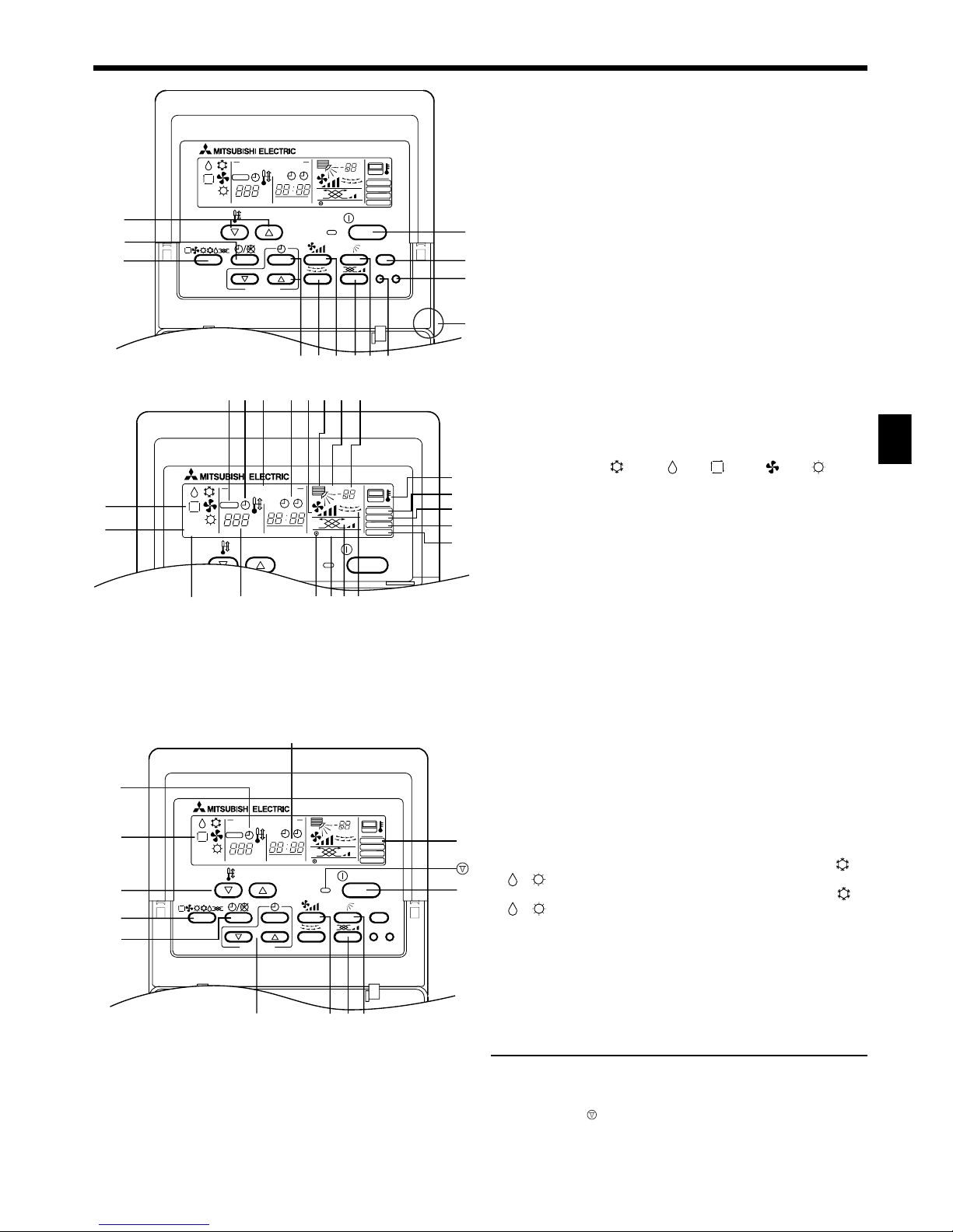
Remote controller-Button
2. Operation
PAR-20MAA
ON/OFF
CENTRALLY CONTROLLED
ERROR CODE
CLOCK
ON OFF
˚C
CHECK
CHECK MODE
FILTER
TEST RUN
FUNCTION
˚C
1Hr.
NOT AVAILABLE
STAND BY
DEFROST
FILTER
CHECK TEST
TEMP.
TIMER SET
1
2
3
456 879
0
C
A
B
1 [Room temperature adjustment] Button
2 [Timer/continuous] Button
3 [Selecting operation] Button
4 [Time selection] Button
[Time-setting] Button
5 [Louver] Button
6 [Fan speed adjustment] Button
7 [Up/down airflow direction] Button
8 [Ventilation] Button
9 [Checking/built-in] Button
0 [Test run] Button
A [Filter] Button
B [ON/OFF] Button
C Position of built-in room temperature sensor
• Never expose the remote controller to direct sunlight. Doing so can result in the erroneous measurement of room temperature.
• Never place any obstacle around the lower right-hand section of the
remote controller. Doing so can result in the erroneous measurement of
room temperature.
ON/OFF
CENTRALLY CONTROLLED
ERROR CODE
CLOCK
ON OFF
˚C
CHECK
CHECK MODE
FILTER
TEST RUN
FUNCTION
˚C
1Hr.
NOT AVAILABLE
STAND BY
DEFROST
TEMP.
ABCD
E
F
HIKLJ
M
P
N
O
R
SQTU
G
Remote controller-Display
A Current time/Timer
B Centralized control
C Timer ON
D Abnormality occurs
E Operation mode: COOL, DRY, AUTO, FAN, HEAT
F Preparing for Heating mode
G Defrost mode
H Set temperature
I Power ON
J Louver
K Not available function
L Ventilation
M Function setting mode
N Test run mode
O Error check mode
P Filter sign
Q Set effective for 1 hr.
R Sensor position
S Room temperature
T Airflow
U Fan speed
Before starting operation
• Start running after the “HO” display has disappeared. The “HO” display
briefly appears on the room temperature display (max. 3 minutes) when
the power is turned on and after a power failure. This does not indicate
any failure of the air conditioner.
• The operation modes of the indoor units’ cooling operation, dry operation, and heating operation are different from those of the outdoor units.
When the operation is started with cooling/dry (heating) and other indoor units connected to the counterpart outdoor units are already running in the same operation mode, the remote control displays “ ” or
“ ” (“ ”) mode. However, the operation comes to stop, and you cannot
get a desired mode. When this occurs, you will be notified by the “ ” or
“ ” (“ ”) display that flashes in the liquid crystal display of the remote
controller. Set to the operation mode of other indoor unit by the operation switch button.
The above does not apply to the models that simultaneously run both
the cooling operation and heating operation.
• The outdoor units stop when all the indoor units connected to the counterpart outdoor units stop.
• During heating operation, even if the indoor unit is set to operation while
the outdoor unit is in defrosting operation, operation starts after the defrosting operation of the outdoor unit has ended.
2.1. Switching the unit on/off
Start an operation
1. Press the
BB
BB
B [ON/OFF] button
Operation lamp lights up and operation starts.
Stop an operation
1. Press the
BB
BB
B [ON/OFF] button again
Operation lamp goes off and operation stops.
TIMER SET
PAR-20MAA
ON/OFF
CENTRALLY CONTROLLED
ERROR CODE
CLOCK
ON OFF
˚C
CHECK
CHECK MODE
FILTER
TEST RUN
FUNCTION
˚C
1Hr.
NOT AVAILABLE
STAND BY
DEFROST
FILTER
CHECK TEST
TEMP.
3
2
E
C
A
1
6
87
4
B
A
Page 4

4
• Once the buttons have been set, pressing of the [ON/OFF] button only
can repeat the same operation thereafter.
• During operation, the operation lamp above the [ON/OFF] button lights
up.
Caution:
Even if the operation button is pressed immediately after the operation is stopped, operation is not restarted for about 3 minutes. This
function protects the machine. It automatically starts operation after
the lapse of approximately 3 minutes.
2.2. Mode select
When selecting operation
1. Press the
33
33
3 [selecting operation] button
Consecutive press of the selecting operation button switches the operation over to E “ ”, “ ”, “ ”, (“ ”), and (“ ”). For the contents of
operation, check the display.
For cooling
Press the
33
33
3 [selecting operation] button and bring up the “ ” dis-
play.
For dry
Press the
33
33
3 [selecting operation] button and bring up the “ ” dis-
play.
• The indoor fan turns to the low-speed operation, disabling the change of
fan speed.
• Dry operation cannot be carried out at a room temperature of less than
18 °C.
For fan
Press the
33
33
3 [selecting operation] button and bring up the “ ” dis-
play.
• The fan operation functions to circulate the air in the room.
• The temperature of the room cannot be set by fan operation.
Caution:
Never expose your body directly to cool air for a long time. Excessive
exposure to cool air is bad for your health, and should therefore be
avoided.
Dry operation
The dry is a microcomputer-controlled dehumidifying operation which controls excessive air-cooling according to the room temperature of your choice.
(Not usable for heating.)
1. Until reaching room temperature of your choice
The compressor and indoor fan function are linked together according
to the change of the room temperature and automatically repeat ON/
OFF.
2. When reaching room temperature of your choice
Both the compressor and indoor fan stop.
When stop continues for 10 minutes, the compressor and indoor fan are
operated for 3 minutes to keep the humidity low.
For heating
Press the
33
33
3 [selecting operation] button to bring up the “ ” display.
Regarding displays during heating operation “DEFROST”
Displayed only during the defrosting operation.
“STAND BY”
Displayed from the start of heating operation until the moment warm air
blows out.
Caution:
• When the air conditioner is used together with burners, thoroughly
ventilate the area. Insufficient ventilation can result in accidents
due to oxygen deficiency.
• Never place a burner at a place where it is exposed to the airflow
from the air conditioner.
Doing so can result in imperfect combustion of the burner.
• The microcomputer functions in the following cases:
• Air does not blow out when heating starts.
- To prevent any cool air from escaping, the indoor fan is gradually
switched in sequence from faint airflow/weak airflow/set airflow according to the temperature rise of the blown out air. Wait a moment
until the airflow comes out naturally.
• The fan is not moving at the set speed.
- In some models, the system switches over to faint airflow when the
temperature of the room reaches the set temperature. In other cases,
2. Operation
it stops to prevent any cool air from escaping during the defrosting
operation.
• Air flows out even if operation is stopped.
- Approximately 1 minute after the stop of operation, the indoor fan
sometimes rotates to eliminate extra heat generated by the electric
heater, etc. The fan speed comes to low or high.
For ventilation
Press the
33
33
3 [selecting operation] button to bring up the “
” dis-
play.
• Used to provide ventilation without using the heat or air conditioning
functions of the unit.
• The
display will not appear when the ventilation equipment is not
attached.
For automatic
Press the
33
33
3 [selecting operation] button to bring up the “ ” dis-
play.
NOTE:
The heating display and the automatic display does not appear on models that
operate exclusively as cooling only air-conditioner.
2.3. Selecting a temperature
TEMP.
To change room temperature
Press the
11
11
1 [room temperature adjustment] button and set the room
temperature of your choice.
Pressing or once changes the setting by 1 °C.
If the pressing is continued, the setting continues to change by 1 °C.
• Indoor temperature can be set within the following range.
Cooling/dry: 19 - 30 °C
Heating: 17 - 28 °C
• It is impossible to set the room temperature by the air-blow operation.
* The range of room temperature display is 8 - 39 °C. Outside this range,
the display flashes either 8 - 39 °C to inform you if the room temperature
is lower or higher than the displayed temperature.
2.4. Selecting a fan speed
To change fan speed
Every time you press the 6 [fan speed] button once, it switches from the
low-speed to high-speed settings successively.
In the electronic dry operation, the indoor fan automatically turns to lowspeed operation. Switching the fan speed is impossible. (Only the display
on the remote controller changes.)
* Every time the fan speed adjustment button is pressed once, the fan
speed is changed.
Display: (Low) → (High)
2.5. Using the timer
1) Set the current time
• Set the current time after turning ON the power of the air conditioner or
after restoration from a power failure.
• It can be set regardless of the operation of the indoor unit.
• During the time operation, the time-setting button becomes void, disa-
bling time setting.
1. Press the
44
44
4 [time selection] button and bring up the
AA
AA
A “current
time” display
• Every time it is pressed, the display changes.
Caution:
When the current time is not yet set, the “CLOCK (current time)” dis-
play flashes, disabling the setting of timer operation.
2. Set the current time by pressing the
44
44
4 or button
• The time cannot be set while the C “timer on” is displayed.
• While the A “CLOCK” time is displayed, press the time setting 4 /
buttons and set the time.
CLOCK
“current
time”
(no display)
“timer end
time”
“timer start
time”
ON
OFF
Page 5

5
TIMER SET
ON/OFF
CLOCK
˚C
˚C
FILTER
CHECK TEST
TEMP.
A
2
1
B
TIMER SET
ON/OFF
CLOCK
ON OFF
˚C
˚C
FILTER
CHECK TEST
TEMP.
1
D
B
2
3
CA
2. Operation
• The setting advances one minute every time the 4 button is pressed
once, and retrogresses one minute every time the 4 button is
pressed once.
When respective 4 / buttons are pressed continuously, the
time display goes fast forward. It advances in the order of 1 minute unit
- 10 minute unit - one hour unit.
• About 10 seconds after the button operation has been completed, the
C “current time” and A “CLOCK” displays disappear.
Caution:
• Remote controller is equipped with a simplified clock with a precision of about + or - one minute per month.
• The time must be re-adjusted (reset) every time the air conditioner
is subjected to a power stop of the air conditioner or a power failure.
2) Timer setting
• If the timer is set, the unit starts (stops) at the set time, and the time
mode is terminated.
• When you wish to confirm the starting and ending time, press the 4
[time selection] button while C “ ” is displayed.
Function of timer
On-timer
Set the on-timer for the time the working day begins in your company.
When the set start time arrives, the air conditioner starts operation.
Off-timer
Use the off-timer as a reminder to turn off the air conditioner. When the set
end-work time arrives, the air conditioner stops operation.
There are three methods for using the timer.
1. ON/OFF Timer: When setting both starting and ending time
2. On-timer: When only setting the starting time
(Ending time is set to “ - - : - - ”)
3. Off-timer: When only setting the ending time
(Starting time is set to “ - - : - - ”)
Display example of timer setting
ON OFF
ON OFF
The example shows a timer set for operation start
at 8:00 and end at 17:00.
1. Press the
22
22
2 [timer/continuous] button and bring up the
CC
CC
C no dis-
play
2. Press the
44
44
4 [time selection] button and bring up the
AA
AA
A “Timer start
time” display
3. Press the
44
44
4
( ) button of the
44
44
4 [time selection] and set
the starting time
When using it as an off-timer, set the starting time to “ - - : - - ”.
The “ - - : - - ” is displayed next to 23:50.
4. Press the
44
44
4 [time selection] button and bring up the
AA
AA
A “Timer end
time” display
5. Press the
44
44
4 ( ) button of the [time switch] and set the
ending time
When using it as an on-timer, set the ending time to “ - - : - - ”.
The “ - - : - - ” is displayed next to 23:50.
6. Press the
22
22
2 [timer/continuous] button and bring up the
CC
CC
C “ ”
display
Bringing up the C “ ” display completes the setting.
Every time the 4 ( ) button of the 4 [timer selection] is pressed
once, it advances (or retrogresses) by 10 minutes.
If the button is pressed continuously, it advances (or retrogresses) continuously.
First set the hour digit and then set the minute digit.
When the ON/OFF timer mode is set, you can run (on-timer) or stop (offtimer) operation by pressing the B [ON/OFF] button even when there is
remaining time.
Release
Press the
22
22
2 [timer/continuous] button and the “ ” display disap-
pears.
3) Ventilator-Airconditioner combined operation
1. If the unit is off, press the B ON/OFF button to turn it on.
The ON indicator should light up.
• The ventilation equipment will operate automatically when connected to
the unit.
2. Press the 8 button.
• You can set the ventilation speed at LOW or HIGH.
4) Changing the ventilation setting
Press the 8 button.
• The setting changes each time the button is pushed.
→
[Low] ← [High]
2.6. Others
CENTRALLY CONTROLLED
: Displayed when control is executed by a sepa-
rately sold centralized control unit, etc.
STAND BY
DEFROST
: Displayed from the start of heating operation un-
til the moment warm air blows out.
CHECK
: This displays indication when some abnormal-
ity occurs in the unit.
NOT AVAILABLE
: When a button is pressed for any function which
the indoor unit cannot perform, this display
flashes concurrently with the display of that function.
: In the system in which the [Sensor] display is
indicated as the “remote controller”, room temperature measurement is performed by the room
temperature sensor built into the remote controller. Therefore, pay attention to the following:
FILTER
: Displayed when it is time to clean the filter.
Press the A [Filter] button twice, then the display will disappear.
ON OFF
ON OFF
Page 6

6
3.1. Cleaning the filters and the indoor unit
Care and cleaning
• Be sure to turn the ON/OFF switch to the OFF position before proceeding with care and handling of the unit.
Cleaning the indoor unit
• Wipe the unit with a dry, soft cloth.
• Do not attempt to pull the vertical air vanes forcibly by hands to prevent
possible damage or malfunction.
• Use a household detergent (for tableware cleaning or cloth washing) to
remove fingerprint and oil stains.
• Do not use gasoline, benzine, thinner, and polishing powder which could
damage the unit.
3. Care and cleaning
A
B
A
C
B
Removing the air filter
Be sure to check on the location and the way of setting with the contractor
when the unit performs a trial run.
A Air intake B Filter C Screw (Only RP·EA)
Cleaning filters
• Air filter cleaning method varies according to filter material. Read instruction concerning filter material and cleaning method carefully. General method for cleaning filters is shown below.
• Tap lightly or clean with vacuum cleaner. Rinse in water or neutral detergent dissolved in lukewarm water if filters are especially dirty. Be sure to
throughly rinse off any detergent used.Dry before reinstalling into air
conditioner.
Caution:
• Do not dry filters in direct sunlight or by other heat sources. Heat
may disfigure filters.
• Washing in hot water (over 50 °C) may disfigure filters.
Page 7

7
Problem
Unit does not cool or heat very well.
The unit stops operating before ar-
riving at the set temperature in the
heating mode.
A white mist is expelled from the indoor unit.
The indicators of the remote controller do not light up when operated.
CENTRALLY CONTROLLED is displayed in the remote controller.
Problem
The start and stop functions are not
available just after restarting the unit.
“H0” is displayed in the remote controller.
An error code is displayed in the remote controller.
The operating display of the wireless
remote controller’s receiver is flashing.
Solution
Wait about three minutes (operation
has stopped to prevent damage to
the air conditioner).
An automatic startup test is being
performed (will last for about three
minutes).
A self-diagnostic function is being
performed to preserve the air conditioner.
*Do not attempt to make repairs
yourself. Turn the main switch off
and contact the dealer from whom
you bought the air conditioner. Provide him or her with the name of the
unit and the information displayed
in the remote controller.
Solution
Clean the filter.
Frost forms when the outdoor tem-
perature is low and humidity is high.
Wait for about 10 minutes for the frost
to melt.
This may occur just after the unit is
turned on when a high level of humidity is present in the room.
Turn on the power switch. “ ” will be
displayed.
The start and stop functions of the
remote controller are not available
when the CENTRALLY CONTROLLED message is lit.
Before you call out a repair man, check the following table to see whether there is a simple solution to your problem.
NOTE: After a power cut, the unit will not restart automatically. You will have to restart it by pressing the POWER - ON/OFF button on the remote controller.
If none of the above apply, turn the main switch off and contact the dealer from whom you bought the air-conditioner, telling him the model name and the
nature of the problem. Do not try to fix the unit yourself.
In any of the following cases, turn off the main power switch
and contact your local dealer for service:
• The operation lamp (on the main unit) flashes.
• The switches do not work properly.
• The circuit breaker trips frequently (or the fuse blows frequently).
• Water has accidentally been splashed into the unit.
• Water leaks from the unit.
• Something is accidentally dropped into the air-conditioner.
• An unusual noise is heard during operation.
The following do not indicate any malfunction:
Odours: smells such as tobacco or cosmetic odours may persist after they have been sucked into the unit.
Sound of liquid flowing inside indoor unit: this can occur during or after operation and is simply the sound of refrigerant being circulated inside the unit.
Ticking sound coming from indoor unit: this can occur when cooling or heating has just begun or has just stopped. It is caused by the indoor unit shrinking
or expanding slightly due to the change in temperature.
The message “CENTRALLY CONTROLLED” appearing on the LCD panel: from time to time, this message may come up on the LCD panel. This does not
indicate any malfunction.
Operating range
Indoor air intake temperature Outdoor air intake temperature
Cooling
Maximum 35 °C DB, 22.5 °C WB 46 °C DB
Minimum 19 °C DB, 15 °C WB –5 °C DB
Heating
Maximum 28 °C DB 21 °C DB, 15 °C WB
Minimum 17 °C DB –11 °C DB, –12 °C WB
4. Troubleshooting
Page 8

8
5. Specification
䡵 PEAD-RP·EA/GA + PU(H)-P·GAA
Indoor model
Capacity (Cooling/Heating) <kW> *1
Total Input (Cooling/Heating) <kW> *1
Indoor power source (<V>/<Hz>)
Indoor dimension (Height) <mm>
Indoor dimension (Width) <mm>
Indoor dimension (Depth) <mm>
Indoor fan airflow rate (L-H) <m
3
/min>
Indoor noise level (L-H) <dB> *2
Indoor net weight <kg>
RP1.6EA
4.45/4.85
1.71/1.73
295
935
700
11-14
34-38
33
䡵 PEAD-RP·EA/GA + PUHZ-RP·VHA
Indoor model
Capacity (Cooling/Heating) <kW> *1
Total Input (Cooling/Heating) <kW> *1
Indoor power source (<V>/<Hz>)
Indoor dimension (Height) <mm>
Indoor dimension (Width) <mm>
Indoor dimension (Depth) <mm>
Indoor fan airflow rate (L-H) <m3/min>
Indoor noise level (L-H) <dB> *2
Indoor net weight <kg>
䡵 PU(H)-P·GAA
Outdoor model
Outdoor power source (<V>/<Hz>)
Outdoor dimension (Height) <mm>
Outdoor dimension (Width) <mm>
Outdoor
dimension (Depth) <mm>
Outdoor
fan airflow rate <m3/min>
Outdoor
net weight <kg>
䡵 PUHZ-RP·VHA
Outdoor model
Outdoor power source (<V>/<Hz>)
Outdoor dimension (Height) <mm>
Outdoor dimension (Width) <mm>
Outdoor
dimension (Depth) <mm>
Outdoor
fan airflow rate <m3/min>
Outdoor
net weight <kg>
*1. Cooling: Indoor 27 °CDB/19 °CWB, Outdoor 35 °CDB
Heating: Indoor 20 °CDB, Outdoor 7 °CDB/6 °CWB
*2. GA model: 50 Pa, 230 V
RP1.6 ~ 2.5EA model: 30 Pa, 230 V
RP3 ~ 6EA model: 70 Pa, 230 V
RP2EA
5.60/6.30
2.53/2.20
295
935
700
13.5-17
36-40
35
RP2.5EA
6.60/7.15
2.65/2.36
295
1175
700
17-21
37-41
42
RP2.5GA
6.60/7.15
2.74/2.50
275
1171
16.5-21
35-40
42
RP3EA
325
1175
44
RP3GA
275
1171
42
RP4EA
3.83/4.00
325
1415
27-34
41-46
62
RP4GA
3.68/3.67
275
1411
26.5-33
42-45
60
RP5EA
12.20/14.00
4.87/4.74
1415
33.5-42
44-50
65
RP6EA
14.00/16.60
5.81/5.90
1715
36.5-46
46-51
70
~/N 220-230-240/50
7.60/9.05
3.35/3.18
20-25
37-41
325
740
9.60/10.30
RP1.6EA
3.60/4.10
1.12/1.26
295
935
700
11-14
34-38
33
RP2EA
4.90/6.00
1.52/1.65
295
935
700
13.5-17
36-40
35
RP2.5EA
6.00/7.00
1.86/1.90
295
1175
700
17-21
37-41
42
RP2.5GA
6.00/7.00
1.68/1.77
275
1171
16.5-21
35-40
42
RP3EA
325
1175
44
RP3GA
275
1171
42
RP4EA
325
1415
27-34
41-46
62
RP4GA
275
1411
26.5-33
42-45
60
RP5EA
12.50/14.00
3.69/4.11
1415
33.5-41
44-50
65
RP6EA
14.00/16.00
4.91/4.76
1715
36.5-46
46-51
70
~/N 220-230-240/50
7.10/8.00
2.15/2.34
20-25
37-41
325
740
10.00/11.20
3.08/3.48
P1.6V
P1.6Y
650
45
54
V: ~/N 220-230-240/50 Y: 3N~380-400-415/50
P2V
P2Y
855
55
74
P2.5V
P2.5Y
855
P3V
P3Y
P4V
P4Y
85
97
P5Y
95
112
P6Y
100
113
900
1260
1050
330+20
50
79
RP1.6
V: ~/N 220-230-240/50
RP2 RP2.5 RP3 RP4 RP5 RP6
943
55
75
950
330+30
600
800
300+15
35
45
1350
100
121
Page 9

Please be sure to put the contact address/telephone number on
this manual before handing it to the customer.
• Low Voltage Directive 73/23/ EEC
• Electromagnetic Compatibility Directive 89/
336/ EEC
This product is designed and intended for use in the residential,
commercial and light-industrial environment.
HEAD OFFICE: MITSUBISHI DENKI BLDG., 2-2-3, MARUNOUCHI, CHIYODA-KU, TOKYO 100-8310, JAPAN
Printed in UNITED KINGDOM
WT04004X04
The product at hand is
based on the following
EU regulations:
Page 10

 Loading...