

Page 1
Page 2
SAFETY PRECAUTIONS
(Please read these instructions before using this equipment.)
Before using this product, please read this manual and the relevant manuals introduced in this manual
carefully and pay full attention to safety to handle the product correctly.
These precautions apply only to this product.
In this manual, the safety instructions are ranked as "DANGER" and "CAUTION".
Indicates that incorrect handling may cause hazardous
Depending on circumstances, procedures indicated by
results.
In any case, it is important to follow the directions for usage.
Please save this manual to make it accessible when required and always forward it to the end user.
DANGER
CAUTION
conditions, resulting in death or severe injury.
Indicates that incorrect handling may cause hazardous
conditions, resulting in medium or slight personal injury or
physical damage.
CAUTION may also be linked to serious
A - 1
Page 3
For Safe Operations
1. Prevention of electric shocks
DANGER
Never open the front case or terminal covers of the servo amplifier while the power is ON or the
unit is running, as this may lead to electric shocks.
Never run the unit with the front case or terminal cover of the servo amplifier removed. The high
voltage terminal and charged sections will be exposed and may lead to electric shocks.
Never open the front case or terminal cover of the servo amplifier at times other than wiring work
or periodic inspections even if the power is OFF. The insides of the position board and servo
amplifier are charged and may lead to electric shocks.
Completely turn off the externally supplied power used in the system before mounting or
removing the position board, performing wiring work, or inspections. Failing to do so may lead to
electric shocks.
When performing wiring work or inspections, turn the power OFF, wait at least ten minutes, and
then check the voltage with a tester, etc. Failing to do so may lead to electric shocks.
Be sure to ground the controller incorporating the position board, servo amplifier and servo
motor. (Ground resistance : 100
The wiring work and inspections must be done by a qualified technician.
Wire the units after installing the position board, servo amplifier and servo motor. Failing to do so
may lead to electric shocks or damage.
Never operate the switches with wet hands, as this may lead to electric shocks.
Do not damage, apply excessive stress, place heavy things on or sandwich the cables, as this
may lead to electric shocks.
Do not touch the position board, servo amplifier or servo motor terminal blocks while the power is
ON, as this may lead to electric shocks.
Do not touch the built-in power supply, built-in grounding or signal wires of the position board
and servo amplifier, as this may lead to electric shocks.
2. For fire prevention
or less) Do not ground commonly with other devices.
CAUTION
Install the position board, servo amplifier, servo motor and regenerative resistor on incombustible.
Installing them directly or close to combustibles will lead to fire.
If a fault occurs in the position board or servo amplifier, shut the power OFF at the servo
amplifier’s power source. If a large current continues to flow, fire may occur.
When using a regenerative resistor, shut the power OFF with an error signal. The regenerative
resistor may abnormally overheat due to a fault in the regenerative transistor, etc., and may lead
to fire.
Always take heat measures such as flame proofing for the inside of the control panel where the
servo amplifier or regenerative resistor is installed and for the wires used. Failing to do so may
lead to fire.
Do not damage, apply excessive stress, place heavy things on or sandwich the cables, as this
may lead to fire.
A - 2
Page 4
3. For injury prevention
CAUTION
Do not apply a voltage other than that specified in this manual and the instruction manual of the
product you are using on any terminal.
Doing so may lead to destruction or damage.
Do not mistake the terminal connections, as this may lead to destruction or damage.
Do not mistake the polarity ( + / - ), as this may lead to destruction or damage.
Do not touch the heat radiating fins of position board or servo amplifier, regenerative resistor and
servo motor, etc., while the power is ON and for a short time after the power is turned OFF. In this
timing, these parts become very hot and may lead to burns.
Always turn the power OFF before touching the servo motor shaft or coupled machines, as these
parts may lead to injuries.
Do not go near the machine during test operations or during operations such as teaching.
Doing so may lead to injuries.
4. Various precautions
Strictly observe the following precautions.
Mistaken handling of the unit may lead to faults, injuries or electric shocks.
(1) System structure
CAUTION
Always install a leakage breaker on the controller incorporating the position board and servo
amplifier power source.
If installation of an electromagnetic contactor for power shut off during an error, etc., is specified in
the instruction manual for the servo amplifier, etc., always install the electromagnetic contactor.
Install the emergency stop circuit externally so that the operation can be stopped immediately and
the power shut off.
Use the position board, servo amplifier, servo motor and regenerative resistor with the correct
combinations listed in the instruction manual. Other combinations may lead to fire or faults.
If safety standards (ex., robot safety rules, etc.,) apply to the system using the position board,
servo amplifier and servo motor, make sure that the safety standards are satisfied.
Construct a safety circuit externally of the position board or servo amplifier if the abnormal
operation of the position board or servo amplifier differ from the safety directive operation in the
system.
In systems where coasting of the servo motor will be a problem during the forced stop, emergency
stop, servo OFF or power supply OFF, use dynamic brakes.
Make sure that the system considers the coasting amount even when using dynamic brakes.
In systems where perpendicular shaft dropping may be a problem during the forced stop,
emergency stop, servo OFF or power supply OFF, use both dynamic brakes and electromagnetic
brakes.
A - 3
Page 5
CAUTION
The dynamic brakes must be used only on errors that cause the forced stop, emergency stop, or
servo OFF. These brakes must not be used for normal braking.
The brakes (electromagnetic brakes) assembled into the servo motor are for holding applications,
and must not be used for normal braking.
The system must have a mechanical allowance so that the machine itself can stop even if the
stroke limits switch is passed through at the max. speed.
Use wires and cables that have a wire diameter, heat resistance and bending resistance
compatible with the system.
Use wires and cables within the length of the range described in the instruction manual.
The ratings and characteristics of the parts (other than position board, servo amplifier and servo
motor) used in a system must be compatible with the position board, servo amplifier and servo
motor.
Install a cover on the shaft so that the rotary parts of the servo motor are not touched during
operation.
There may be some cases where holding by the electromagnetic brakes is not possible due to the
life or mechanical structure (when the ball screw and servomotor are connected with a timing belt,
etc.). Install a stopping device to ensure safety on the machine side.
(2) Parameter settings and programming
CAUTION
Set the parameter values to those that are compatible with the position board, servo amplifier,
servo motor and regenerative resistor model and the system application. The protective functions
may not function if the settings are incorrect.
The regenerative resistor model and capacity parameters must be set to values that conform to
the operation mode and servo amplifier. The protective functions may not function if the settings
are incorrect.
Set the mechanical brake output and dynamic brake output validity parameters to values that are
compatible with the system application. The protective functions may not function if the settings
are incorrect.
Set the stroke limit input validity parameter to a value that is compatible with the system
application. The protective functions may not function if the setting is incorrect.
Set the servo motor encoder type (increment, absolute position type, etc.) parameter to a value
that is compatible with the system application. The protective functions may not function if the
setting is incorrect.
Set the servo motor capacity and type (standard, low-inertia, flat, etc.) parameter to values that
are compatible with the system application. The protective functions may not function if the
settings are incorrect.
Set the servo amplifier capacity and type parameters to values that are compatible with the
system application. The protective functions may not function if the settings are incorrect.
Use the program commands for the program with the conditions specified in the instruction
manual.
A - 4
Page 6

(3) Transportation and installation
CAUTION
Transport the product with the correct method according to the mass.
Use the servo motor suspension bolts only for the transportation of the servo motor. Do not
transport the servo motor with machine installed on it.
Do not stack products past the limit.
When transporting, installing, and removing the position board, never touch the print board
inner part and electronic components. Hold the front panel or edge of the print board.
When transporting the position board or servo amplifier, never hold the connected wires or
cables.
When transporting the servo motor, never hold the cables, shaft or detector.
When transporting the position board or servo amplifier, never hold the front case as it may fall
off.
When transporting, installing or removing the position board or servo amplifier, never hold the
edges.
Install the unit according to the instruction manual in a place where the mass can be withstood.
Do not get on or place heavy objects on the product.
Always observe the installation direction.
Mount the position board to a connector or slot that is compatible with standards, and keep the
designated clearance between the position board and other boards.
Keep the designated clearance between the position board or servo amplifier and control panel
inner surface or the position board and servo amplifier, position board or servo amplifier and
other devices.
Do not install or operate position board, servo amplifiers or servo motors that are damaged or
that have missing parts.
Do not block the intake/outtake ports of the servo amplifier and servo motor with cooling fan.
Do not allow conductive matter such as screw or cutting chips or combustible matter such as oil
enter the position board, servo amplifier or servo motor.
The position board, servo amplifier and servo motor are precision machines, so do not drop or
apply strong impacts on them.
Securely fix the position board, servo amplifier and servo motor to the machine according to the
instruction manual. If the fixing is insufficient, these may come off during operation.
A - 5
Page 7

CAUTION
Always install the servo motor with reduction gears in the designated direction. Failing to do so
may lead to oil leaks.
Store and use the unit in the following environmental conditions.
Environment
Position board/Servo amplifier Servomotor
Ambient
temperature
Ambient humidity According to each instruction manual.
Storage
temperature
Atmosphere
Altitude 1000m (3280.84ft.) or less above sea level
Vibration According to each instruction manual
According to each instruction manual.
According to each instruction manual.
Indoors (where not subject to direct sunlight).
No corrosive gases, flammable gases, oil mist or dust must exist
Conditions
0°C to +40°C (With no freezing)
(32°F to +104°F)
80% RH or less
(With no dew condensation)
-20°C to +65°C
(-4°F to +149°F)
When coupling with the synchronous encoder or servo motor shaft end, do not apply impact such
as by hitting with a hammer. Doing so may lead to detector damage.
Do not apply a load larger than the tolerable load onto the synchronous encoder and servo motor
shaft. Doing so may lead to shaft breakage.
When not using for a long time, disconnect the power line from the servo amplifier.
Place the position board and servo amplifier in static electricity preventing vinyl bags and store.
When storing for a long time, please contact with our sales representative.
Also, execute a trial operation.
When fumigants that contain halogen materials such as fluorine, chlorine, bromine, and iodine
are used for disinfecting and protecting wooden packaging from insects, they cause malfunction
when entering our products.
Please take necessary precautions to ensure that remaining materials from fumigant do not
enter our products, or treat packaging with methods other than fumigation (heat method).
Additionally, disinfect and protect wood from insects before packing products.
A - 6
Page 8
(4) Wiring
CAUTION
Correctly and securely wire the wires. Reconfirm the connections for mistakes and the terminal
screws for tightness after wiring. Failing to do so may lead to run away of the servo motor.
After wiring, install the protective covers such as the terminal covers to the original positions.
Do not install a phase advancing capacitor, surge absorber or radio noise filter (option FR-BIF)
on the output side of the servo amplifier.
Correctly connect the output side (terminal U, V, W) and ground. Incorrect connections will lead
the servo motor to operate abnormally.
Do not connect a commercial power supply to the servo motor, as this may lead to trouble.
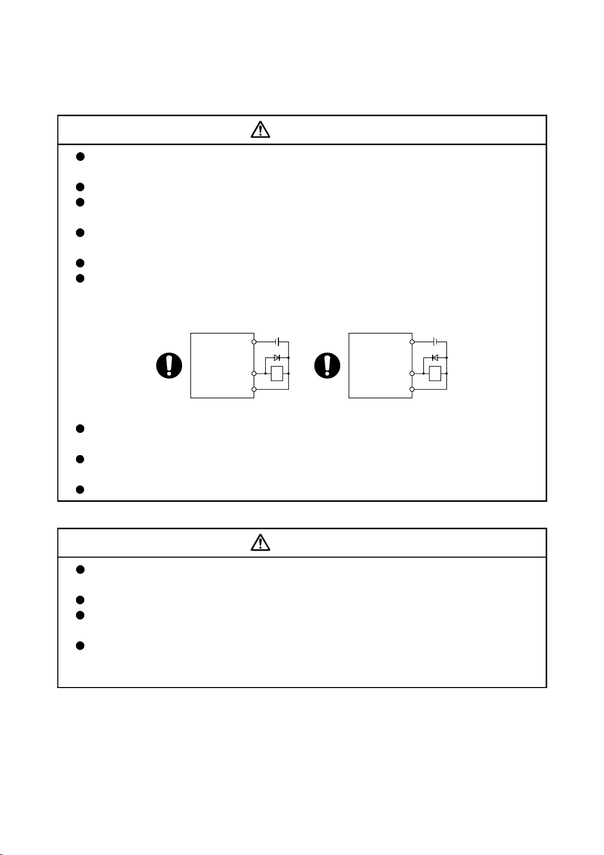
Do not mistake the direction of the surge absorbing diode installed on the DC relay for the control
signal output of brake signals, etc. Incorrect installation may lead to signals not being output
when trouble occurs or the protective functions not functioning.
Servo amplifier
DOCOM
24VDC
Servo amplifier
DOCOM
24VDC
Control output
signal
DICOM
For the sink output interface For the source output interface
RA
Control output
signal
DICOM
RA
Do not connect or disconnect the connection cables between each unit or the encoder cable
while the power is ON.
Securely tighten the cable connector fixing screws and fixing mechanisms. Insufficient fixing may
lead to the cables coming off during operation.
Do not bundle the power line or cables.
(5) Trial operation and adjustment
CAUTION
Confirm and adjust the program and each parameter before operation. Unpredictable
movements may occur depending on the machine.
Extreme adjustments and changes may lead to unstable operation, so never make them.
When using the absolute position system function, on starting up, and when the position board
or absolute value motor has been replaced, always perform a home position return.
Before starting test operation, set the parameter speed limit value to the slowest value, and
make sure that operation can be stopped immediately by the forced stop, etc. if a hazardous
state occurs.
A - 7
Page 9
(6) Usage methods
CAUTION
Immediately turn OFF the power if smoke, abnormal sounds or odors are emitted from the
position board, servo amplifier or servo motor.
Always execute a test operation before starting actual operations after the program or
parameters have been changed or after maintenance and inspection.
Do not attempt to disassemble and repair the units excluding a qualified technician whom our
company recognized.
Do not make any modifications to the unit.
Keep the effect or electromagnetic obstacles to a minimum by installing a noise filter or by using
wire shields, etc. Electromagnetic obstacles may affect the electronic devices used near the
position board or servo amplifier.
When using the CE Mark-compliant equipment, refer to this manual for the position boards and
refer to the corresponding EMC guideline information for the servo amplifiers, inverters and other
equipment.
Use the units with the following conditions.
Item Conditions
Input power According to each instruction manual.
Input frequency According to each instruction manual.
Tolerable momentary power failure According to each instruction manual.
(7) Corrective actions for errors
CAUTION
If an error occurs in the self diagnosis of the position board or servo amplifier, confirm the check
details according to the instruction manual, and restore the operation.
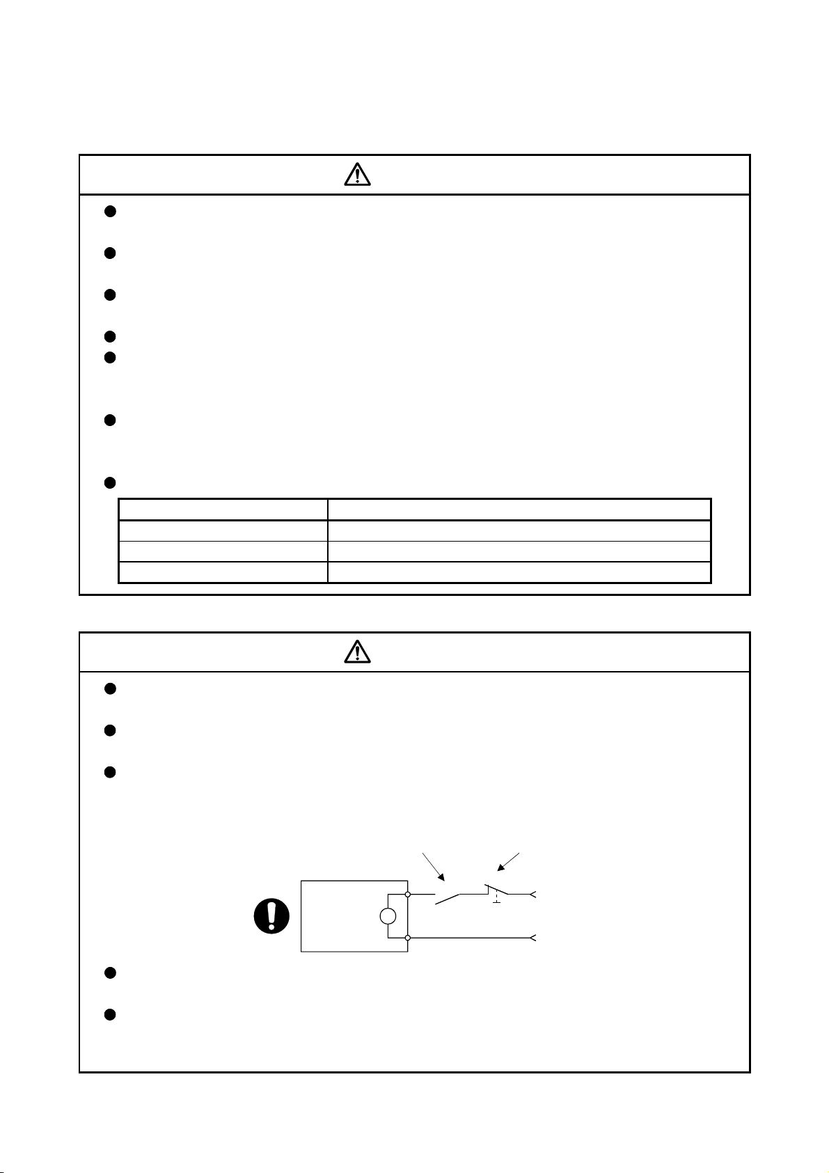
If a dangerous state is predicted in case of a power failure or product failure, use a servo motor
with electromagnetic brakes or install a brake mechanism externally.
Use a double circuit construction so that the electromagnetic brake operation circuit can be
operated by emergency stop signals set externally.
Shut off with servo ON signal OFF,
alarm, electromagnetic brake signal.
Servo motor
RA1
Electromagnetic
brakes
B
Shut off with the
emergency stop
signal (EMG).
EMG
24VDC
If an error occurs, remove the cause, secure the safety and then resume operation after alarm
release.
The unit may suddenly resume operation after a power failure is restored, so do not go near the
machine. (Design the machine so that personal safety can be ensured even if the machine
restarts suddenly.)
A - 8
Page 10

(8) Maintenance, inspection and part replacement
CAUTION
Perform the daily and periodic inspections according to the instruction manual.
Perform maintenance and inspection after backing up the program and parameters for the
position board and servo amplifier.
Do not place fingers or hands in the clearance when opening or closing any opening.
Periodically replace consumable parts such as batteries according to the instruction manual.
Do not touch the lead sections such as ICs or the connector contacts.
Before touching the position board, always touch grounded metal, etc. to discharge static
electricity from human body. Failure to do so may cause the position board to fail or malfunction.
Do not directly touch the position board's conductive parts and electronic components.
Touching them could cause an operation failure or give damage to the position board.
Do not place the position board or servo amplifier on metal that may cause a power leakage or
wood, plastic or vinyl that may cause static electricity buildup.
Do not perform a megger test (insulation resistance measurement) during inspection.
When replacing the position board or servo amplifier, always set the new position board
settings correctly.
When the position board or absolute value motor has been replaced, carry out a home position
return operation from the user program. Failing to do so may cause position displacement.
After maintenance and inspections are completed, confirm that the position detection of the
absolute position detector function is correct.
Do not drop or impact the battery installed to the module.
Doing so may damage the battery, causing battery liquid to leak in the battery. Do not use the
dropped or impacted battery, but dispose of it.
Do not short circuit, charge, overheat, incinerate or disassemble the batteries.
The electrolytic capacitor will generate gas during a fault, so do not place your face near the
position board or servo amplifier.
The electrolytic capacitor and fan will deteriorate. Periodically replace these to prevent secondary
damage from faults. Replacements can be made by our sales representative.
Lock the control panel and prevent access to those who are not certified to handle or install
electric equipment.
Do not burn or break a position board and servo amplifier. Doing so may cause a toxic gas.
A - 9
Page 11

(9) About processing of waste
When you discard position board, servo amplifier, a battery (primary battery) and other option articles,
please follow the law of each country (area).
CAUTION
This product is not designed or manufactured to be used in equipment or systems in situations
that can affect or endanger human life.
When considering this product for operation in special applications such as machinery or systems
used in passenger transportation, medical, aerospace, atomic power, electric power, or
submarine repeating applications, please contact your nearest Mitsubishi sales representative.
Although this product was manufactured under conditions of strict quality control, you are strongly
advised to install safety devices to forestall serious accidents when it is used in facilities where a
breakdown in the product is likely to cause a serious accident.
(10) General cautions
All drawings provided in the instruction manual show the state with the covers and safety
partitions removed to explain detailed sections. When operating the product, always return the
covers and partitions to the designated positions, and operate according to the instruction
manual.
A - 10
Page 12

REVISIONS
The manual number is given on the bottom left of the back cover.
Print Date Manual Number Revision
Dec., 2013 IB(NA)-0300223-A First edition
Dec., 2014 IB(NA)-0300223-B [Additional model]
MR-MC240, MR-MC241
[Additional function]
Speed-torque control, Mark detection, Continuous operation to torque
control, External forced stop disabled
[Additional correction]
Alarm history, Home position return change while system is running,
High speed monitor position droop, Table map, Log data (event code
list, information for each event), Parameters (servo parameters,
control parameters), Monitor number (operation information), Alarm
number (system alarm, operation alarm), Supplementary explanation
for the use of linear servo system, Supplementary explanation for the
use of SSCNET
compatible servo amplifier, Connector exterior
dimensions
Japanese Manual Number IB(NA)-0300222
This manual confers no industrial property rights or any rights of any other kind, nor does it confer any patent
licenses. Mitsubishi Electric Corporation cannot be held responsible for any problems involving industrial property
rights which may occur as a result of using the contents noted in this manual.
© 2013 MITSUBISHI ELECTRIC CORPORATION
A - 11
Page 13

INTRODUCTION
Thank you for choosing the Mitsubishi position board MR-MC210/MR-MC211/MR-MC240/MR-MC241.
Before using the equipment, please read this manual carefully to develop full familiarity with the functions
and performance of the position board you have purchased, so as to ensure correct use.
CONTENTS
Safety Precautions ......................................................................................................................................... A- 1
Revisions ........................................................................................................................................................A-11
Contents .........................................................................................................................................................A-12
About Manuals ................................................................................................................................................A-21
1. SUMMARY 1- 1 to 1-24
1.1 Summary ................................................................................................................................................... 1- 1
1.2 Features..................................................................................................................................................... 1- 6
1.3 Specifications ............................................................................................................................................ 1- 9
1.3.1 General specifications ........................................................................................................................ 1- 9
1.3.2 List of specifications of position board .............................................................................................. 1-10
1.4 Name of each section .............................................................................................................................. 1-13
1.4.1 Name of parts for PCI bus compatible position board ..................................................................... 1-13
®
1.4.2 Name of parts for PCI Express
bus compatible position board ..................................................... 1-15
1.5 Bus interface ............................................................................................................................................. 1-17
1.5.1 Configuration register ........................................................................................................................ 1-17
1.5.2 Dual port memory map...................................................................................................................... 1-19
1.5.3 Module information ............................................................................................................................ 1-20
1.6 SSCNET
cables .................................................................................................................................... 1-22
1.7 Forced stop input terminal ....................................................................................................................... 1-23
2. SYSTEM CONFIGURATION 2- 1 to 2- 8
2.1 Position board configuration ..................................................................................................................... 2- 1
2.1.1 MR-MC210 system configuration ...................................................................................................... 2- 1
2.1.2 MR-MC211 system configuration ...................................................................................................... 2- 2
2.1.3 MR-MC240 system configuration ...................................................................................................... 2- 3
2.1.4 MR-MC241 system configuration ...................................................................................................... 2- 4
2.2 System configuration equipment .............................................................................................................. 2- 5
2.3 Checking serial number and operating system software version ............................................................ 2- 6
2.3.1 Checking serial number ..................................................................................................................... 2- 6
2.3.2 Checking software version ................................................................................................................. 2- 6
2.4 Restrictions by the Software's Version ..................................................................................................... 2- 7
3. INSTALLATION AND WIRING 3- 1 to 3- 6
3.1 Board installation ....................................................................................................................................... 3- 1
3.1.1 Instructions for handling ..................................................................................................................... 3- 1
3.1.2 Installation environment ..................................................................................................................... 3- 1
3.2 Connection and disconnection of cable.................................................................................................... 3- 2
3.2.1 SSCNET
cable ................................................................................................................................ 3- 2
A - 12
Page 14

3.2.2 Forced stop input cable ...................................................................................................................... 3- 6
4. SYSTEM STARTUP 4- 1 to 4-18
4.1 Startup procedures .................................................................................................................................... 4- 1
4.2 Check of wiring and ambient environm ent ............................................................................................... 4- 2
4.3 Position board setting ................................................................................................................................ 4- 3
4.4 Servo amplifier setting ............................................................................................................................... 4- 4
4.5 Parameter setting ...................................................................................................................................... 4- 6
4.5.1 Parameter initialization ....................................................................................................................... 4- 6
4.5.2 System option 1 setting ...................................................................................................................... 4- 7
4.5.3 System option 2 setting ...................................................................................................................... 4- 9
4.5.4 Control option 1 setting ..................................................................................................................... 4-10
4.5.5 Axis No. assignment.......................................................................................................................... 4-11
4.5.6 Sensor input option setting................................................................................................................ 4-13
4.5.7 Vendor ID and type code setting ...................................................................................................... 4-16
4.6 System startup processing ...................................................................................................................... 4-17
5. OPERATIONAL FUNCTIONS 5- 1 to 5-42
5.1 JOG operation ........................................................................................................................................... 5- 2
5.1.1 Summary ............................................................................................................................................ 5- 2
5.1.2 Start operation method ....................................................................................................................... 5- 2
5.1.3 Resuming operation ........................................................................................................................... 5- 3
5.2 Incremental feed ........................................................................................................................................ 5- 4
5.2.1 Summary ............................................................................................................................................ 5- 4
5.2.2 Start operation method ....................................................................................................................... 5- 5
5.3 Automatic operation .................................................................................................................................. 5- 6
5.3.1 Summary ............................................................................................................................................ 5- 6
5.3.2 Start operation method ....................................................................................................................... 5- 7
5.3.3 Auxiliary command ............................................................................................................................. 5- 8
5.3.4 Other axes start specification ............................................................................................................ 5-15
5.3.5 S-curve ratio ...................................................................................................................................... 5-15
5.4 Linear interpolation ................................................................................................................................... 5-16
5.4.1 Summary ........................................................................................................................................... 5-16
5.4.2 Settings .............................................................................................................................................. 5-18
5.4.3 Start operation method ...................................................................................................................... 5- 19
5.4.4 Processing for exceeding speed limit for each axis ......................................................................... 5-20
5.4.5 Restrictions ........................................................................................................................................ 5-21
5.5 Home position return ................................................................................................................................ 5-22
5.5.1 Summary ........................................................................................................................................... 5-22
5.5.2 Home position return method ........................................................................................................... 5-24
5.5.3 Start operation method ...................................................................................................................... 5- 25
5.5.4 Home position return using a dog method ....................................................................................... 5-27
5.5.5 Home position return using a data set method ................................................................................ 5-29
5.5.6 Home position return using a stopper method ................................................................................. 5-29
5.5.7 Home position return using a dog cradle method ............................................................................ 5-30
5.5.8 Home position return using a limit switch combined method........................................................... 5-32
5.5.9 Home position return using a limit switch front end method ............................................................ 5-32
5.5.10 Home position return using a dog front end method ...................................................................... 5-33
A - 13
Page 15

5.5.11 Home position return using a Z-phase detection method .............................................................. 5-35
5.5.12 Home position return using a scale home position signal detection method ................................ 5-38
5.5.13 Home position return using a scale home position signal detection method 2 ............................. 5-39
5.6 Home position reset function (data set function) ..................................................................................... 5-40
6. APPLICATION FUNCTIONS 6- 1 to 6-146
6.1 Command units ......................................................................................................................................... 6- 1
6.1.1 Position command unit - electronic gear ........................................................................................... 6- 1
6.1.2 Settings ............................................................................................................................................... 6- 3
6.1.3 Setting example of electronic gears .................................................................................................. 6- 3
6.1.4 Restrictions ......................................................................................................................................... 6- 4
6.2 Speed unit ................................................................................................................................................. 6- 5
6.2.1 Settings ............................................................................................................................................... 6- 5
6.2.2 Setting example of speed units .......................................................................................................... 6- 6
6.2.3 Speed limit .......................................................................................................................................... 6- 6
6.3 Acceleration/deceleration .......................................................................................................................... 6- 7
6.3.1 Linear acceleration/deceleration ........................................................................................................ 6- 7
6.3.2 Smoothing filter ................................................................................................................................... 6- 8
6.3.3 Start up speed validity ........................................................................................................................ 6- 8
6.3.4 S-curve acceleration/deceleration (Sine acceleration/deceleration) ................................................ 6- 9
6.4 Servo off ................................................................................................................................................... 6-13
6.5 Forced stop ............................................................................................................................................... 6-14
6.6 Stop operation .......................................................................................................................................... 6-15
6.7 Rapid stop operation ................................................................................................................................ 6-16
6.8 Limit switch (stroke end) .......................................................................................................................... 6-17
6.9 Software limit ............................................................................................................................................ 6-18
6.10 Interlock .................................................................................................................................................. 6-20
6.11 Rough match output ............................................................................................................................... 6-22
6.12 Torque limit ............................................................................................................................................. 6-23
6.13 Command change .................................................................................................................................. 6-24
6.13.1 Speed change ................................................................................................................................. 6-24
6.13.2 Change of time constants ............................................................................................................... 6-25
6.13.3 Position change ............................................................................................................................... 6-26
6.14 Backlash ................................................................................................................................................. 6-32
6.15 Position switch ........................................................................................................................................ 6-33
6.16 Completion of operation signal .............................................................................................................. 6-34
6.17 Interference check function .................................................................................................................... 6-40
6.17.1 Interface ........................................................................................................................................... 6-42
6.17.2 Interference check operation image diagram ................................................................................. 6-43
6.17.3 Checks prior to start up ................................................................................................................... 6-44
6.17.4 Operation check .............................................................................................................................. 6-45
6.18 Home position search limit ..................................................................................................................... 6-48
6.18.1 Summary ......................................................................................................................................... 6-48
6.18.2 Set items .......................................................................................................................................... 6-48
6.18.3 Home position search limit operation example .............................................................................. 6-49
6.19 Gain changing ........................................................................................................................................ 6-50
6.20 PI-PID switching ..................................................................................................................................... 6-52
6.21 Absolute position detection system ....................................................................................................... 6-53
6.21.1 Parameters ...................................................................................................................................... 6-53
A - 14
Page 16

6.21.2 Processing procedure ..................................................................................................................... 6-54
6.21.3 Sequence example ......................................................................................................................... 6-56
6.22 Home position return request ................................................................................................................ 6-58
6.23 Other axes start ...................................................................................................................................... 6-60
6.23.1 Summary ......................................................................................................................................... 6-60
6.23.2 Settings ............................................................................................................................................ 6-60
6.23.3 Interface ........................................................................................................................................... 6-66
6.23.4 Operation example .......................................................................................................................... 6-69
6.24 High response I/F ................................................................................................................................... 6-73
6.24.1 Summary ......................................................................................................................................... 6-73
6.24.2 Interface ........................................................................................................................................... 6-74
6.24.3 Fast start operation ......................................................................................................................... 6-75
6.24.4 Interrupt processing high speed completion .................................................................................. 6-76
6.25 In-position signal .................................................................................................................................... 6-77
6.26 Digital input/output ................................................................................................................................. 6-78
6.26.1 Summary ......................................................................................................................................... 6-78
6.26.2 Interface ........................................................................................................................................... 6-79
6.27 Servo amplifier general input/output ...................................................................................................... 6-80
6.27.1 Summary ......................................................................................................................................... 6-80
6.27.2 Settings ............................................................................................................................................ 6-82
6.28 Dual port memory exclusive control ...................................................................................................... 6-85
6.28.1 Summary ......................................................................................................................................... 6-85
6.28.2 Exclusive control of digital output ................................................................................................... 6-85
6.29 Pass position interrupt............................................................................................................................ 6-87
6.29.1 Summary ......................................................................................................................................... 6-87
6.29.2 Pass position interrupt setting method ........................................................................................... 6-88
6.29.3 Interface ........................................................................................................................................... 6-89
6.29.4 Operation example ........................................................................................................................ 6-100
6.30 Mark detection ...................................................................................................................................... 6-104
6.30.1 Summary ....................................................................................................................................... 6-104
6.30.2 Interface ......................................................................................................................................... 6-108
6.30.3 Function details ............................................................................................................................. 6-116
6.30.4 Operation example ........................................................................................................................ 6-118
6.31 Continuous operation to torque control ............................................................................................... 6-121
6.31.1 Summary ....................................................................................................................................... 6-121
6.31.2 Interface ......................................................................................................................................... 6-123
6.31.3 Control mode switch ...................................................................................................................... 6-134
6.31.4 Operation timing ............................................................................................................................ 6-136
6.31.5 Operation during continuous operation to torque control mode .................................................. 6-140
6.31.6 Stop factors during continuous operation to torque control ......................................................... 6-141
6.31.7 Combinations of continuous operation to torque control and other functions ............................. 6-143
6.31.8 Restrictions on servo amplifier functions ..............................................................................
........ 6-145
XILIARY FUNCTION 7- 1 to 7-108
AU
7.
7.1 Reading/writing parameters ...................................................................................................................... 7- 1
7.1.1 Writing par ameters ............................................................................................................................. 7- 1
7.1.2 Reading parameters ........................................................................................................................... 7- 3
7.2 Changing parameters at the servo ........................................................................................................... 7- 4
7.3 Alarm and system error ............................................................................................................................. 7- 6
A - 15
Page 17

7.4 Monitor function ......................................................................................................................................... 7- 8
7.4.1 Summary ............................................................................................................................................ 7- 8
7.4.2 Monitor latch function ........................................................................................................................ 7-10
7.5 High speed monitor function .................................................................................................................... 7-11
7.5.1 Summary ........................................................................................................................................... 7-11
7.5.2 Monitor latch function ........................................................................................................................ 7-12
7.6 Interrupt .................................................................................................................................................... 7-13
7.6.1 Interrupt sequence ............................................................................................................................ 7-13
7.6.2 Interrupt conditions ............................................................................................................................ 7-15
7.6.3 Factor of interrupt .............................................................................................................................. 7-16
7.6.4 Interrupt processing example............................................................................................................ 7-24
7.7 User watchdog function ........................................................................................................................... 7-25
7.8 Software reboot function .......................................................................................................................... 7-26
7.9 Parameter backup .................................................................................................................................... 7-27
7.10 Test mode ............................................................................................................................................... 7-31
7.10.1 Structural diagram ........................................................................................................................... 7-31
7.10.2 Test operation mode ....................................................................................................................... 7-32
7.11 Reconnect/disconnect function .............................................................................................................. 7-33
7.11.1 Disconnection function summary .................................................................................................... 7-33
7.11.2 Reconnect function summary ......................................................................................................... 7-34
7.11.3 Interface ........................................................................................................................................... 7-35
7.11.4 Disconnection method..................................................................................................................... 7-36
7.11.5 Reconnection method ..................................................................................................................... 7-37
7.11.6 Restrictions ...................................................................................................................................... 7-38
7.12 Sampling ................................................................................................................................................. 7-39
7.12.1 Summary ......................................................................................................................................... 7-39
7.12.2 Command/status bit ........................................................................................................................ 7-40
7.12.3 Command/status data ..................................................................................................................... 7-43
7.12.4 Sampling setting write/read ............................................................................................................. 7-46
7.12.5 Details for sampling function settings ............................................................................................. 7- 47
7.12.6 Number of sampled points .............................................................................................................. 7-53
7.12.7 Sampling items ................................................................................................................................ 7-54
7.12.8 Sampling trigger .............................................................................................................................. 7-60
7.12.9 Sampling data read ......................................................................................................................... 7-63
7.12.10 Timing chart for sampling function ................................................................................................ 7-65
7.13 Log .......................................................................................................................................................... 7-74
7.13.1 Summary ......................................................................................................................................... 7-74
7.13.2 Log data details ............................................................................................................................... 7-75
7.13.3 Event code list ................................................................................................................................. 7-76
7.13.4 Information for each event .............................................................................................................. 7-78
7.13.5 Log function interface ...................................................................................................................... 7-87
7.13.6 Timing chart for reading of log data ................................................................................................ 7-90
7.13.7 Log acquiring selection ................................................................................................................... 7-90
7.14 Operation cycle monitor function ........................................................................................................... 7-91
7.14.1 Summary ................................................................................................................
2 Interface ........................................................................................................................................... 7-91
4.
7.1
7.14.3 Operation timing .............................................................................................................................. 7-92
7.15 External forced stop disabled ................................................................................................................ 7-94
7.15.1 Summary ......................................................................................................................................... 7-94
7.15.2 Interface ........................................................................................................................................... 7-94
......................... 7-91
A - 16
Page 18

7.15.3 Setting method ................................................................................................................................ 7-94
7.16 Amplifier-less axis function .................................................................................................................... 7-95
7.16.1 Summary ......................................................................................................................................... 7-95
7.16.2 Interface ........................................................................................................................................... 7-95
7.16.3 Control details .................................................................................................................................. 7-96
7.17 Alarm history function............................................................................................................................. 7-97
7.17.1 Summary ......................................................................................................................................... 7-97
7.17.2 Alarm history data details ................................................................................................................ 7-98
7.17.3 Interface ......................................................................................................................................... 7-103
7.17.4 Timing chart for alarm history read ............................................................................................... 7-106
7.17.5 Alarm history initialization pr ocedure ............................................................................................ 7-107
7.17.6 List of system errors that do not apply to alarm history storage .................................................. 7-107
8. TANDEM DRIVE 8- 1 to 8-32
8.1 Drive modes .............................................................................................................................................. 8- 1
8.1.1 Synchronous mode ............................................................................................................................ 8- 2
8.1.2 Non-synchronous micro-adjustment control mode ........................................................................... 8- 2
8.1.3 Changing of drive mode ..................................................................................................................... 8- 3
8.2 Parameter settings .................................................................................................................................... 8- 4
8.2.1 Designation of tandem drive axes ..................................................................................................... 8- 4
8.2.2 Servo parameters ............................................................................................................................... 8- 4
8.2.3 Control parameters ............................................................................................................................. 8- 4
8.3 Axis data classifications ............................................................................................................................ 8- 5
8.3.1 Only data from master axis is valid .................................................................................................... 8- 5
8.3.2 Individual data for master axis/slave axis .......................................................................................... 8- 5
8.4 Tandem drive axis operation .................................................................................................................... 8- 6
8.4.1 Home position return during tandem drive ........................................................................................ 8- 6
8.4.2 JOG operation during tandem drive ................................................................................................. 8-24
8.4.3 Incremental feed while using tandem drive ...................................................................................... 8-25
8.4.4 Automatic operation during tandem drive ......................................................................................... 8-26
8.4.5 Linear interpolation during tandem drive .......................................................................................... 8-27
8.5 Servo on and servo off during tandem drive axis operation ................................................................... 8-29
8.6 Tandem drive axis limit switch ................................................................................................................. 8-30
8.7 Tandem drive axis software limit ............................................................................................................. 8-31
8.8 Tandem drive interference check ............................................................................................................ 8-31
8.9 Tandem drive axis servo alarms .............................................................................................................. 8-32
8.10 Deviation monitoring function ................................................................................................................ 8-32
9. INTERFACE MODE 9- 1 to 9-40
9.1 Summary ................................................................................................................................................... 9- 1
9.2 Combinations with functions ..................................................................................................................... 9- 2
9.3 Parameters ................................................................................................................................................ 9- 4
9.4 Interface ..................................................................................................................................................... 9- 6
9.5 Control method ......................................................................................................................................... 9-11
9.5.1 Control mode ..................................................................................................................................... 9-11
9.5.2 Position control mode ........................................................................................................................ 9-12
9.5.3 Speed control mode .......................................................................................................................... 9-14
9.5.4 Torque control mode ......................................................................................................................... 9-16
A - 17
Page 19

9.5.5 Control method for interrupt output invalid ....................................................................................... 9-18
9.5.6 Control method for interrupt output valid .......................................................................................... 9- 21
9.5.7 Procedure for switching control mode .............................................................................................. 9-26
9.5.8 Examples of switching control mode ................................................................................................ 9-28
9.6 Interrupt output cycle ................................................................................................................................ 9-31
9.7 Command data update cycle ................................................................................................................... 9-32
9.8 Servo off ................................................................................................................................................... 9-33
9.9 Home position return ................................................................................................................................ 9-34
9.10 Coordinate management ....................................................................................................................... 9-36
9.10.1 Incremental system ......................................................................................................................... 9-36
9.10.2 Absolute position system ................................................................................................................ 9-38
9.11 Precautions............................................................................................................................................. 9-40
10. TABLE MAP 10- 1 to 10-52
10.1 Table list ................................................................................................................................................ 10- 1
10.2 System information ............................................................................................................................... 10- 3
10.3 System command/status table ............................................................................................................. 10- 5
10.4 Factor of interrupt ................................................................................................................................. 10-17
10.5 System configuration information table ............................................................................................... 10-25
10.6 Axis data ............................................................................................................................................... 10-26
10.6.1 Axis data command table .............................................................................................................. 10-26
10.6.2 Axis data status table .................................................................................................................... 10-33
10.7 Servo parameter change number ........................................................................................................ 10-41
10.8 Point number offset .............................................................................................................................. 10-45
10.9 Command buffers ................................................................................................................................. 10-46
10.10 Digital input/output table .................................................................................................................... 10-48
10.11 Mark detection command/status table .............................................................................................. 10-49
10.12 Mark detection data tables ................................................................................................................. 10- 50
10.13 Continuous operation to torque control data table ............................................................................ 10-51
11. PARAMETERS 11- 1 to 11-36
11.1 System parameters ............................................................................................................................... 11- 2
11.2 Servo parameters .................................................................................................................................. 11- 4
11.2.1 Servo amplifier MR-J4(W
11.3 Control parameters .............................................................................................................................. 11-22
12. MONITOR NUMBER 12- 1 to 12-20
12.1 Servo information (1)............................................................................................................................. 12- 1
12.2 Servo information (2)............................................................................................................................. 12- 3
12.3 Operation information ........................................................................................................................... 12- 8
12.4 Operation information (double word) ................................................................................................... 12-11
12.5 System information .............................................................................................................................. 12-12
12.6 Servo parameter information ............................................................................................................... 12-1 4
13. ALARM NUMBER 13- 1 to 13-12
13.1 System alarm ........................................................................................................................................ 13- 1
13.2 Servo alarm ........................................................................................................................................... 13- 2
13.3 Operation alarm..................................................................................................................................... 13- 4
13.4 System error ......................................................................................................................................... 13-11
)- B .................................................................................................... 11- 4
A - 18
Page 20

14. EMC AND LOW VOLTAGE DIRECTIVES 14- 1 to 14- 6
14.1 Requirements for compliance with the EMC directive ......................................................................... 14- 1
14.1.1 Standards relevant to the EMC directive ....................................................................................... 14- 2
14.1.2 Installation instructions for EMC directive ..................................................................................... 14- 3
14.1.3 Parts of measure against noise ..................................................................................................... 14- 5
14.2 Requirements for compliance with the low voltage directive ............................................................... 14- 6
APPENDIX App.- 1 to App.-82
App. 1 Supplementary explanation for the use of linear servo system .................................................. App.- 1
App. 1.1 Position board ........................................................................................................................ App.- 1
App. 1.2 Position board utility software ................................................................................................ App.- 1
App. 1.3 Servo amplifier ....................................................................................................................... App.- 1
App. 1.4 Operations and functions of the linear servo system ........................................................... App.- 2
App. 2 Supplementary explanation for the use of fully closed loop system ........................................... App.-13
App. 2.1 Position board ........................................................................................................................ App.-13
App. 2.2 Position board utility software ................................................................................................ App.-13
App. 2.3 Servo amplifier ....................................................................................................................... App.-13
App. 2.4 Operations and functions of the fully closed loop control ..................................................... App.-14
App. 3 Supplementary explanation for the use of direct drive servo system ......................................... App.-21
App. 3.1 Position board ........................................................................................................................ App.-21
App. 3.2 Position board utility software ................................................................................................ App.-21
App. 3.3 Servo amplifier ....................................................................................................................... App.-21
App. 3.4 Operations and functions of the direct drive servo system .................................................. App.-22
App. 4 Supplementary explanation for the use of multiple-axis servo amplifier (MR-J4W
App. 4.1 Position board ........................................................................................................................ App.-28
App. 4.2 Position board utility software ................................................................................................ App.-28
App. 4.3 Servo amplifier ....................................................................................................................... App.-28
App. 4.4 Operations and functions of the servo amplifier ................................................................... App.-28
App. 5 Supplementary explanation for the use of SSCNET
(MR-J3(W)-
App. 5.1 Position board ........................................................................................................................ App.-30
App. 5.2 Position board utility software ................................................................................................ App.-30
App. 5.3 Connectable units .................................................................................................................. App.-30
App. 5.4 System setting ....................................................................................................................... App.-31
App. 5.5 System configuration ............................................................................................................. App.-31
App. 5.5.1 System configuration diagram ....................................................................................... App.-31
App. 5.6 Axis No. setting ...................................................................................................................... App.-32
App. 5.6.1 Servo amplifier setting .................................................................................................... App.-32
App. 5.7 Parameter setting .................................................................................................................. App.-33
App. 5.7.1 System option 1 setting .................................................................................................. App.-33
App. 5.8 Control option 1 setting .......................................................................................................... App.-35
App. 5.9 Axis No. assignment .............................................................................................................. App.-36
App. 5.10 Sensor input option setting .................................................................................................. App.-38
App. 5.11 Vendor ID and type code setting ......................................................................................... App.-41
App. 5.12 System startup processing .................................................................................................. App.-41
App. 5.13 Restrictions when using J3 compatibility mode .................................................................. App.-42
App. 5.14 Supported functions ............................................................................................................. App.-44
App. 5.14.1 Application functions .................................................................................................... App.-46
B) ........................................................................................................................... App.-30
compatible servo amplifier
- B) ....... App.-28
A - 19
Page 21

App. 5.14.2 Auxiliary function .......................................................................................................... App.-50
App. 5.15 Table map ............................................................................................................................ App.-51
App. 5.15.1 Table list ....................................................................................................................... App.-52
App. 5.15.2 System information ...................................................................................................... App.-53
App. 5.15.3 Servo parameter change number ................................................................................ App.-54
App. 5.16 Parameters .......................................................................................................................... App.-55
App. 5.16.1 System parameters ...................................................................................................... App.-55
App. 5.16.2 Servo parameters ......................................................................................................... App.-56
App. 5.16.3 Control parameters ...................................................................................................... App.-63
App. 5.17 Monitor ................................................................................................................................. App.-64
App. 5.17.1 Servo information (1) .................................................................................................... App.-64
App. 5.17.2 Servo information (2) .................................................................................................... App.-66
App. 5.17.3 Servo parameter information ....................................................................................... App.-71
App. 5.18 System alarm ....................................................................................................................... App.-73
App. 5.18.1 Servo alarm .................................................................................................................. App.-73
App. 6 Cables ........................................................................................................................................... App.-74
App. 6.1 SSCNET
cables .................................................................................................................. App.-74
App. 6.2 Forced stop input cable ......................................................................................................... App.-77
App. 6.3 SSCNET
cables (SC-J3BUS M-C) manufactured by Mitsubishi Electric System &
Service.................................................................................................................................... App.-78
App. 7 Exterior dimensions ...................................................................................................................... App.-79
App. 7.1 PCI bus compatible position board ....................................................................................... App.-79
App. 7.2 PCI Express
®
bus compatible position board ....................................................................... App.-80
App. 7.3 Connector ............................................................................................................................... App.-81
A - 20
Page 22

About Manuals
The following manuals are also related to this product.
In necessary, order them by quoting the details in the tables below.
Related Manuals
(1) Position Board
MR-MC210/MR-MC211/MR-MC240/MR-MC241 Position Board User's Manual (Details)
This manual explains specifications of the position board, information on how to establish a system,
maintenance/inspection, trouble shooting, functions for the positioning control of the position board,
programming, dual port memory and others.
Manual Name
Manual Number
(Model Code)
IB-0300223
(1XB968)
MR-MC210/MR-MC211/MR-MC240/MR-MC241 Position Board User's Manual (API Library)
This manual explains the library of functions and others that the host controller uses to control the position
board.
IB-0300225
(1XB970)
A - 21
Page 23
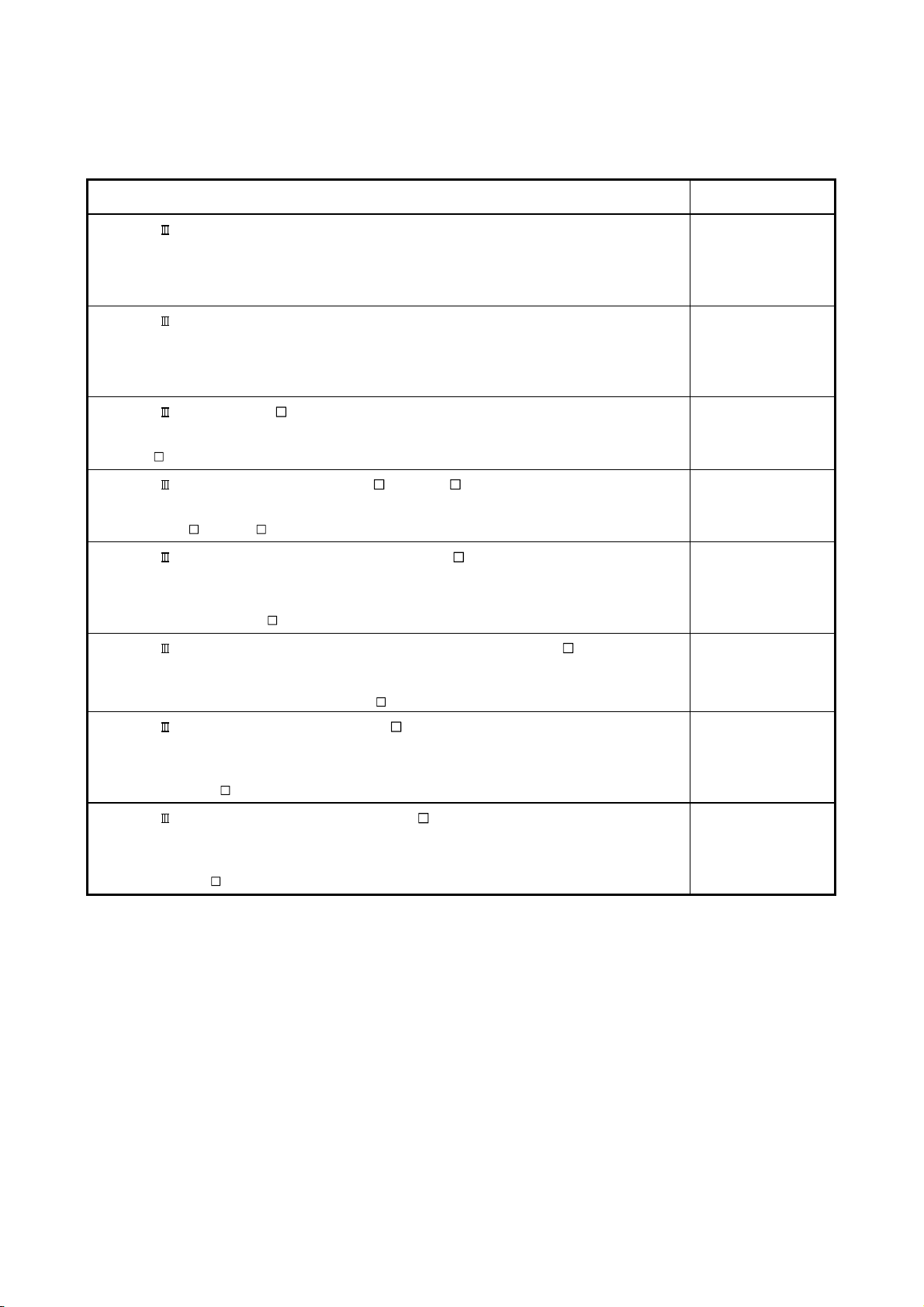
(2) Servo amplifier
SSCNET /H interface AC Servo MR-J4_B(-RJ)/MR-J4_B4(-RJ)/MR-J4_B1(-RJ) Servo
amplifier Instruction Manual
This manual explains the I/O signals, parts names, parameters, start-up procedure and others for AC
Servo MR-J4_B(-RJ)/MR-J4_B4(-RJ)/MR-J4_B1(-RJ) Servo amplifier.
SSCNET /H interface Multi-axis AC Servo MR-J4W2-_B/MR-J4W3-_B Servo amplifier
Instruction Manual
This manual explains the I/O signals, parts names, parameters, start-up procedure and others for Multi-
axis AC Servo MR-J4W2-_B/MR-J4W3-_B Servo amplifier.
Manual Name
Manual Number
(Model Code)
SH-030106
(1CW805)
SH-030105
(1CW806)
SSCNET interface MR-J3- B Servo amplifier Instruction Manual
This manual explains the I/O signals, parts names, parameters, start-up procedure and others for
MR-J3-
B Servo amplifier.
SSCNET Compatible Linear Servo MR-J3- B-RJ004U Instruction Manual
This manual explains the I/O signals, parts names, parameters, start-up procedure and others for Linear
Servo MR-J3-
B-RJ004U Servo amplifier.
SSCNET Compatible Fully Closed Loop Control MR-J3- B-RJ006 Servo amplifier
Instruction Manual
This manual explains the I/O signals, parts names, parameters, start-up procedure and others for Fully
Closed Loop Control MR-J3-
B-RJ006 Servo amplifier.
SSCNET interface 2-axis AC Servo AmplifierMR-J3W-0303BN6/MR-J3W- B Servo
amplifier Instruction Manual
This manual explains the I/O signals, parts names, parameters, start-up procedure and others for 2-axis
AC Servo Amplifier MR-J3W-0303BN6/MR-J3W-
B Servo amplifier.
SSCNET Interface Direct Drive Servo MR-J3- B-RJ080W Servo amplifier Instruction
Manual
This manual explains the I/O signals, parts names, parameters, start-up procedure and others for Direct
Drive Servo MR-J3-
B-RJ080W Servo amplifier.
SSCNET interface Drive Safety integrated MR-J3- B Safety Servo amplifier Instruction
Manual
This manual explains the I/O signals, parts names, parameters, start-up procedure and others for safety
integrated MR-J3-
B Safety Servo amplifier.
SH-030051
(1CW202)
SH-030054
(1CW943)
SH-030056
(1CW304)
SH-030073
(1CW604)
SH-030079
(1CW601)
SH-030084
(1CW205)
A - 22
Page 24
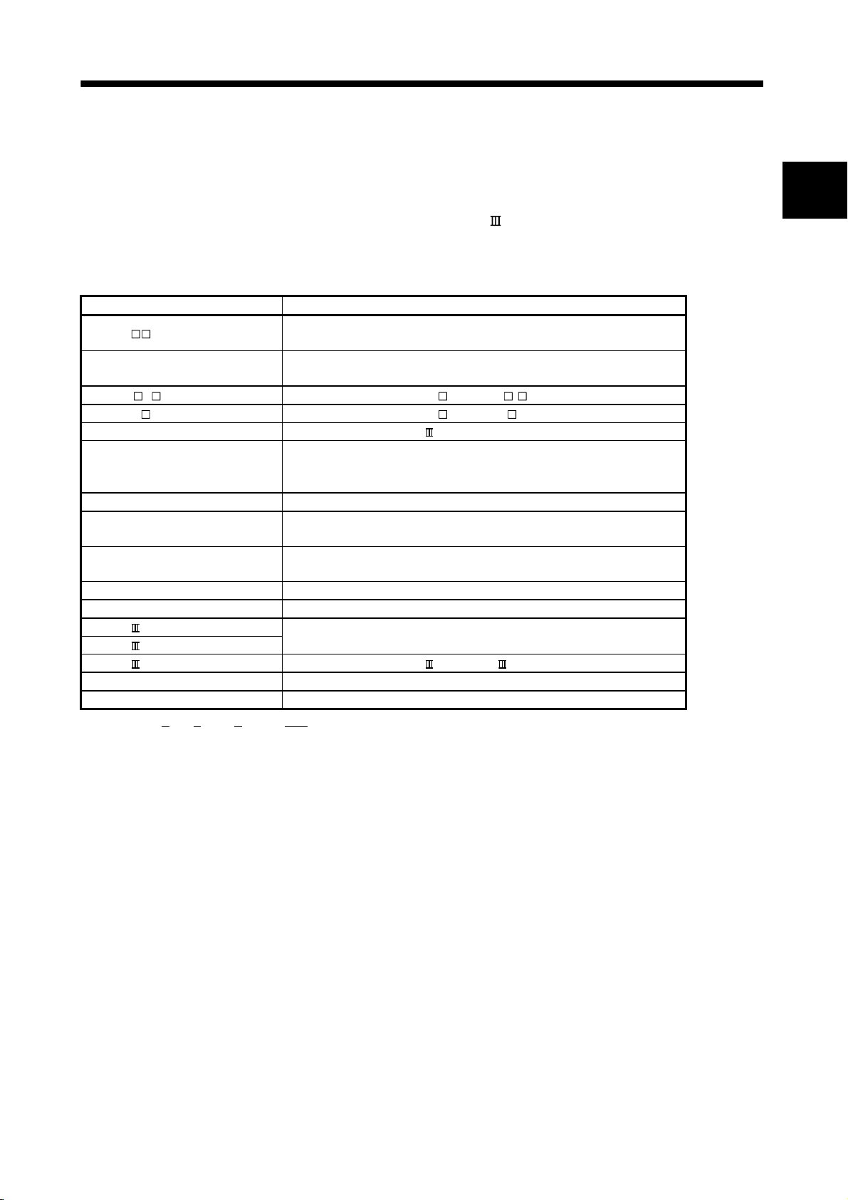
1. SUMMARY
1. SUMMARY
1.1 Summary
This manual describes the specifications and handling of SSCNET
/H compatible position board
(MR-MC210/MR-MC211/MR-MC240/MR-MC241).
In this manual, the following abbreviations are used.
Generic term/Abbreviation Description
MR-MC2 or position board
Host controller
MR-J4(W )- B Servo amplifier model MR-J4- B/MR-J4W - B
MR-J3(W)- B Servo amplifier model MR-J3- B/MR-J3W- B
Servo amplifier General name for SSCNET /H compatible servo amplifier.
Utility software
Test tool Abbreviation for start-up and examination tool for position board.
API library
MR Configurator2
User program Program created by the user that operates on the host controller.
System program Internal program that controls the position board.
SSCNET /H(Note)
SSCNET (Note)
SSCNET (/H)(Note) General name for SSCNET /H, SSCNET .
Board Ver. System version of position board.
API Ver. Software version of the API library for position board.
Note. SSCNET: Servo System Controller NETwork
General name for PCI bus compatible position board MR-MC210/MR-MC211/
PCI Express
General name for computer equipped with position board and operates user
program.
General name for the Position Board Utility2 (MRZJW3-MC2-UTL) which
includes test tool for start-up and examination, and the API library for position
board.
General name for the library of functions for positioning control that the host
controller uses to control the position board.
Abbreviation for the Servo set-up software MR Configurator2 version 1.10L or
later.
High-speed synchronized network between the position board and the servo
amplifier.
®
bus compatible position board MR-MC240/MR-MC241
1
1 - 1
Page 25
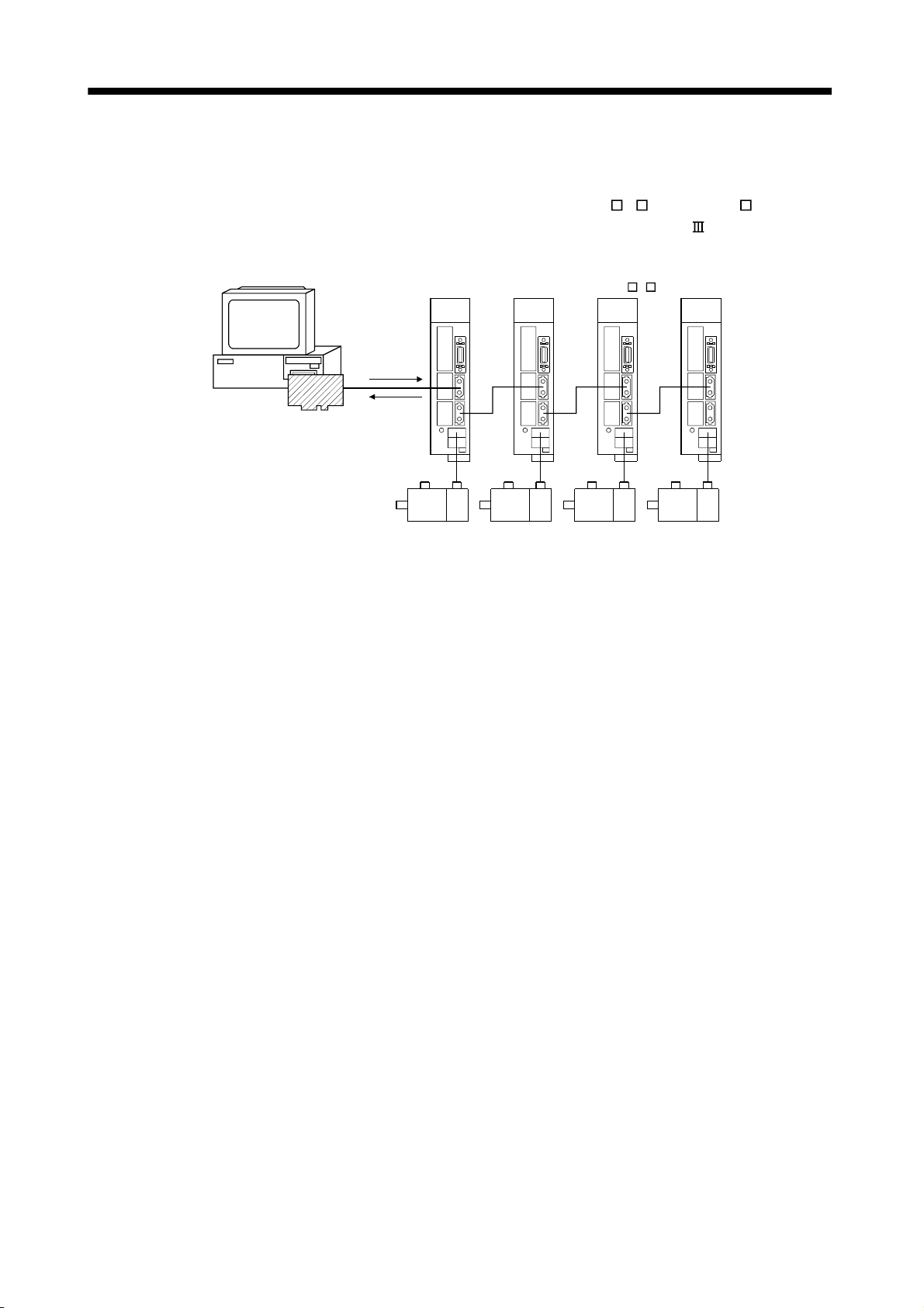
1. SUMMARY
(1) PCI bus compatible position board
The PCI bus compatible position board (MR-MC210/MR-MC211) is a board compatible with PCI bus
mounted to the host controller and controls our servo amplifiers (MR-J4(W
bus compatible position board and the servo amplifiers are connected with SSCNET
)- B/MR-J3(W)- B). The PCI
/H, which is a high
speed synchronous network.
Host controller
Position
instructions
parameters
Servo amplifier (MR-J4(W )- B)Servo amplifier (MR-J4(W )- B)
Position
board
Position
feedback
Speed
feedback
For the PCI bus compatible position board, there are two types, MR-MC210 and MR-MC211.
The MR-MC210 has one SSCNET control channel (hereinafter: CH) and one SSCNET line (hereinafter:
line), and can control positioning for up to 20 axes. The MR-MC211 has one SSCNET control channel and
two SSCNET lines, and can control positioning for up to 32 axes (up to 20 axes per line). By reading and
writing the dual port memory mapped to the memory space of the PCI bus, the host controller can
command position board to start operation, and get servo amplifier status. The host controller can also
receive position pass and positioning complete interruptions via PCI bus.
The position board is equipped with standard mode and interface mode for positioning control. The
positioning control mode that corresponds with the application can be selected by parameter. The mode
cannot be changed during SSCNET communication (while system is running). Positioning in standard
mode is performed using a point table mapped on the dual port memory of the position board. Arbitrary
positioning is possible by writing data to this point table from the host controller.
Also, startup of JOG operation and home position return, etc. as well as parameters changing and
monitoring are possible through accessing this dual port memory on the position board from the host
controller.
Interface mode is a sequential positioning command method that uses a user program on the host
controller. The user program controls the servo amplifier with an arbitrary acceleration/deceleration pattern
by writing the position command to the position command buffer of the position board every communication
cycle (control cycle). Some functions from standard mode cannot be used, or are restricted when in
interface mode.
1 - 2
Page 26
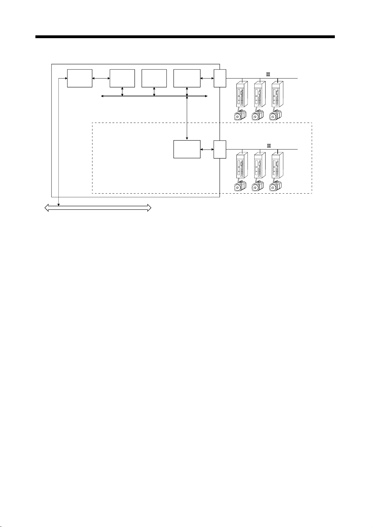
1. SUMMARY
Bus
interface
Dual port
memory
PCI bus
CPU
Local bus
SSCNET
Communi-
cation IC
SSCNET
Communi-
cation IC
CH1
CH2
Inside the dotted line: only when using MR-MC211
SSCNET /H
(Max 20 axes)
SSCNET /H
(Max 12 axes)
1 - 3
Page 27
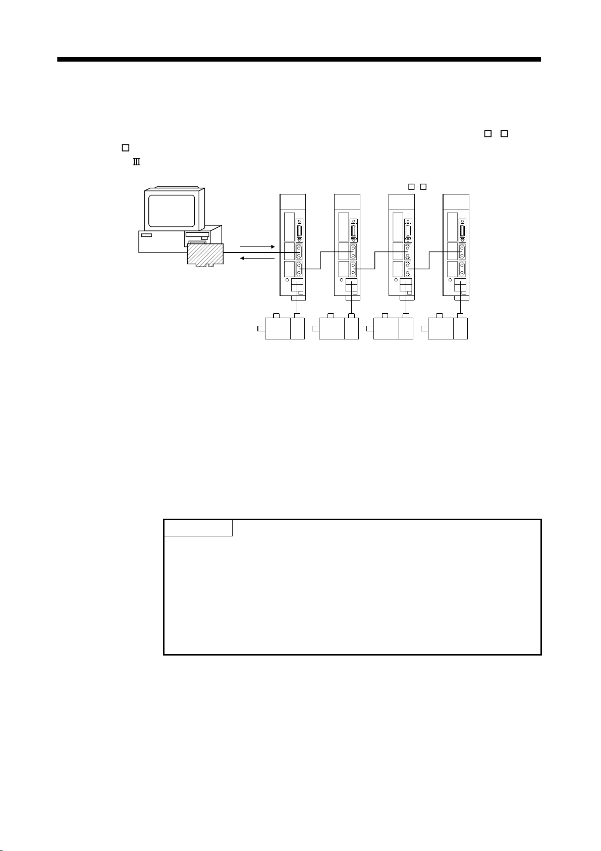
1. SUMMARY
(2) PCI Express
The PCI Express
Express
MR-J3(W)with SSCNET
®
bus compatible position board
®
®
bus mounted to a PCI Express® system and controls our servo amplifiers (MR-J4(W )- B/
bus compatible position board (MR-MC240/MR-MC241) is a board compatible with PCI
B). The PCI Express® bus compatible position board and the servo amplifiers are connected
/H, which is a high speed synchronous network.
Host controller
Position
board
Position
instructions
parameters
Position
feedback
Speed
feedback
Servo amplifier (MR-J4(W )- B)Servo amplifier (MR-J4(W )- B)
For the PCI Express
®
bus compatible position board, there are two types, MR-MC240 and MR-MC241.
The MR-MC240 has one SSCNET control channel (hereinafter: CH) and one SSCNET communication line
(hereinafter: line), and can control positioning for up to 20 axes. The MR-MC241 has one SSCNET control
channel and two SSCNET communication lines, and can control positioning for up to 32 axes (up to 20
axes per communication line). Positioning is performed using a point table mapped on the dual port
®
memory of the PCI Express
bus compatible position board. Arbitrary positioning is possible by writing data
to this point table from the PCI bus compatible host controller.
Also, startup of JOG operation and home position return, etc. as well as parameter changing and
monitoring are possible through accessing this dual port memory on the position board from the host
®
controller. The dual port memory is mapped on the memory space of the PCI Express
bus.
POINT
• Depending on the specifications of the host controller, the PCI Express® slot
may be directly connected to the CPU of the host controller.
®
If the PCI Express
compatible position board is mounted to a PCI Express
slot that is directly connected to the CPU of the host controller, it may not be
able to operate.
®
Mount the PCI Express
compatible position board to a PCI Express® slot that
is not directly connected to the CPU of the host controller (connected to a
chipset).
®
1 - 4
Page 28
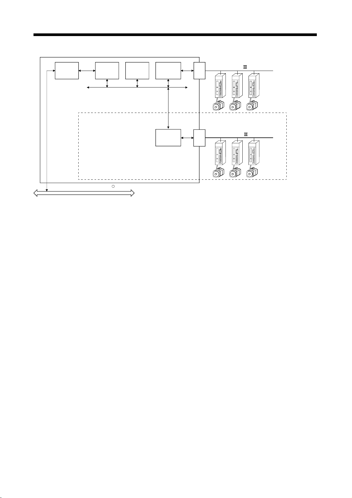
1. SUMMARY
Bus
interface
Dual port
memory
PCI Express bus
R
CPU
Local bus
SSCNET
Communi-
cation IC
SSCNET
Communi-
cation IC
CH1
CH2
Inside the dotted line: only when using MR-MC241
SSCNET /H
(Max 20 axes)
SSCNET /H
(Max 12 axes)
1 - 5
Page 29

1. SUMMARY
1.2 Features
The position board has the following features.
(1) Structuring of SSCNET
The position board can be directly connected to the Mitsubishi servo amplifiers of MR-J4-B series using
SSCNET
(a) By connecting the position board and servo amplifier and servo amplifiers with a high speed
synchronous network by SSCNET
between the position board and servo amplifier, or servo amplifier and servo amplifier for the SSCNET
cable on the same bus is 100(328.08)[m(ft.)]. This increases flexibility at system design.
(b) By using SSCNET
servo amplifiers and such is reduced.
(c) The servo parameters can be set on the position board side and written to the servo amplifier, or read
from the servo amplifier using the SSCNET communication.
(d) The current feedback position and error description contained in the servo can be checked by the dual
port memory of the position board.
(e) Communication between MR Configurator2 and the servo amplifiers is possible via the position board
USB.
(2) Programming in C programming language with the API library
Positioning control for the servo in C programming language is enabled with the API library included with
the Position Board Utility2 (MRZJW3-MC2-UTL).
(3) Supports event-driven programming
The host controller is notified by interrupt via PCI bus when the conditions for an interrupt such as passing
through a preset point or positioning complete are met. The user program can create event-driven
programs according to interrupt factors.
(4) High-speed operation starting time
High-speed operation starting time within the control cycle (0.22ms fastest) is achieved for the maximum
number of synchronous startup axes or less.
/H.
/H communication servo system by computer control
/H, the reduction of wiring is achieved. The maximum distance
cable (optical communication), the influence of electromagnetic noise etc. from
1 - 6
Page 30

1. SUMMARY
(5) Wide variety of positioning control functions
The main functions (such as home position return control, standard mode, and interface mode (sequential
positioning command method)) which are required for any positioning system and the sub functions which
limit and add functions to those controls are supported.
(a) Enhanced home position return control
Additional features of home position return control
Ten home position return methods are provided: dog cradle method, dog method, data set method,
continuous operation to torque method, limit switch combined method, scale home position signal
detection method, limit switch front end method, dog front end method, Z-phase detection method, and
scale home position signal detection method 2. Select an applicable method according to the system.
(b) Wide variety of control methods
Positioning control methods such as positioning control are provided.
1) Independent control of each axis
Position control can be performed independently for each axis at any given timing.
2) Interpolation control
Interpolation controls using multiple axes can be performed.
(2-axis to 4-axis linear interpolation control)
3) Tandem drive
Tandem drive for 2 axes can be performed. In scale home position signal detection method and scale
home position signal detection method 2, the deviation between the 2 axes at home position return
can be compensated.
4) Interface mode
The user program controls the servo amplifier with an arbitrary acceleration/deceleration pattern that
is not supported in standard mode by writing the position command to the position command buffer of
(6) Supports other axes start function
(7) High maintainability
the position board every communication cycle (control cycle).
(c) Continuous processing of multiple positioning data
Multiple positioning data can be processed continuously within one operation start.
(d) Acceleration/deceleration processing
Four acceleration/deceleration processing methods are provided: Linear acceleration/deceleration,
S-curve acceleration/deceleration, start up speed, and smoothing filter.
The acceleration/deceleration curve can be selected according to the machine characteristic.
With the other axes start function, the position board can determine the conditions and automatically start
other axes, and turn on/off output signals. The position board does not go through user program processing
so there are no delays or dispersions. This also lessens the load on the user program.
Maintainability is enhanced in the position board.
(a) Data retention without battery
Parameter data can be stored in the flash ROM inside the position board. This feature allows the
retaining of data without a battery.
(b) Alarm collection function
The alarm details when an alarm occurs are automatically stored in the flash ROM inside the position
board.
Storing the alarm information allows the user to check the alarm from the user program or test tool even
after the position board is powered off or reset.
1 - 7
Page 31

1. SUMMARY
(8) Setting, monitoring, and testing through test tool
Using the test tool of Position Board Utility2 (MRZJW3-MC2-UTL), users can check the validity of the preset
parameters and point table by performing test operation of the position board before creating a user
program.
The control monitor/graph function allows users to debug programs efficiently.
(9) Forced stop function
The batch forced stop is available for connected servo amplifiers by the forced stop input signal of the
external input.
(10) Easy application to the absolute position system
(a) The MR-J4(W
Absolute position system can be used by connecting the battery for absolute position system to the
servo amplifier.
(b) Once the home position has been established, the home position return operation is unnecessary at the
system's power supply ON.
(c) With the absolute position system, the data set method home position return is used to establish the
home position. The wiring of proximity dog, etc. is unnecessary.
)- B series servo amplifiers and servo motors support the absolute position system.
1 - 8
Page 32

1. SUMMARY
1.3 Specifications
1.3.1 General specifications
General specifications of the position board are shown below.
Items Specification
Operating ambient temperature 0 to 55°C (32 to 131°F)
Storage ambient temperature -20 to 65°C (4 to 149°F)
Operating ambient humidity 10 to 90% RH, non-condensing
Storage ambient humidity 10 to 90% RH, non-condensing
Operating ambience Indoors (where not subject to direct sunlight), no corrosive gas, no significant amount of dirt or dust
Cooling method Self cooling
MR-MC210 MR-MC211 MR-MC240 MR-MC241
Power supply
Power supply
voltage
Leakage current
5VDC ± 5% 3.3VDC ± 9%
Less than
450mA
Less than
700mA
Less than
1100mA
Less than
1500mA
CAUTION
The position board must be stored and used under the conditions listed in the table of
specifications above.
When not using for a long time, disconnect the power line from the servo amplifier.
Place the position board and servo amplifier in static electricity preventing vinyl bags and store.
When storing for a long time, please contact with our sales representative.
Also, execute a trial operation.
1 - 9
Page 33

1. SUMMARY
1.3.2 List of specifications of position board
(1) Position board control specifications
Function
System
function
Operation
function
(Note 1, 2)
Application
function
Note 1. The position board can move within the limits of -2147483648 to 2147483647. Movement outside the limits is not covered with
warranty. If software limits have been disabled, be careful not to move it outside of the physical limits.
2. For the absolute position detection system, the command limits of the position after calculation using the electronic gear are
also -2147483648 to 2147483647. It is possible for the moveable limits to be narrower than -2147483648 to 2147483647,
depending on the electronic gear.
Control cycle 0.88ms/0.44ms/0.22ms (Select using parameters.)
Control axes Max 20 Max 32 Max 20 Max 32
Control mode Standard mode: Position controlling method by position
SSCNET communication SSCNET /H, SSCNET
JOG operation Provided
Incremental feed Provided
Automatic operation Point table method, 1 axis control,
Linear interpolation Point table method, MAX 4 axes interpolation is
Home position return Dog cradle method, Dog method, Data set method,
Electronic gear
Speed units Command unit/min, command unit/s, and r/min can be
Acceleration/deceleration Command speed limits: 1 to speed limit
Stop function Forced stop, Stop operation, Rapid stop operation
Limit switch Provided (Hardware stroke limit)
Software limit Provided (Software stroke limit)
Interlock Provided
Rough match output Provided
Torque limit Provided
Command change Location, speed, time constant
Backlash Provided
Position switch Provided
Completion of operation signal Provided
Interference check Provided Unavailable when the
Home position search limit Provided
MR-MC210 MR-MC211 MR-MC240 MR-MC241
Interface mode : Sequential positioning command
Continuous operation to torque control
available
Stopper method, Limit switch combined method, Scale
home position signal detection method,
Limit switch front end method, Dog front end method,
Z-phase detection method,
Scale home position signal detection method 2
Home position reset (data set) The current position can
Electronic gear numerator
Electronic gear denominator
selected.
Limits of Start speed: 1 to speed limit
Time constant limits: 0 to 20000 ms/speed limit
Separate setting of constants for deceleration and
acceleration: provided
Setting of constants for separate points: provided
Acceleration/deceleration method:
Linear acceleration/deceleration,
smoothing filter, start up speed,
S-curve acceleration/deceleration
(sine acceleration/deceleration)
Contents
board
method by user program
: 1 to 5242879
: 1 to 589823
Remarks
Unavailable when the
control cycle is 0.22ms
Can indicate direction
for home position return
Proximity dog is for level
detection
Can change home
position return method
while system is running
be reset to the home
position
control cycle is 0.22ms
1 - 10
Page 34

1. SUMMARY
Function
Application
function
Help function Reading/writing parameters Provided
Tandem drive Up to 2 axes × 8 groups
Interface mode Positioning control, speed-torque control
Board ID 0 to 3 Select using DIP-SW
DI Limit switch None DI signals are input from
DO None
Note 3. This is not the watch dog for the CPU on the position board.
Gain switching Provided
PI-PID switching Provided
Absolute position detection
system
Home position return request Provided
Other axes start Provided
High response I/F Provided
In-position signal Provided
Digital input/output Provided
Servo amplifier general
input/output
Dual port memory exclusive
control
Pass position interrupt Provided
Mark detection Provided
Continuous operation to torque
control
Changing parameters at the
servo
Alarm and system error Provided
Monitor Current command position, Current feedback position,
High speed monitor Current command position, Current feedback position,
Interrupt
User watchdog function Provided (Check for the watchdog of the of the user
Software reboot function Provided
Parameter backup Parameters can be saved to the flash ROM.
Test mode By connecting MR Configurator2 via the position board,
Reconnect/disconnect function Provided
Sampling
Log History of start operation, alarms, etc, can be recorded.
Operation cycle monitor function Provided
External forced stop disabled Provided
Amplifier-less axis function Provided
Alarm history function Alarm history is saved to the flash ROM.
Limit switch None
Proximity dog None
Forced stop 1 point
MR-MC210 MR-MC211 MR-MC240 MR-MC241
Provided
Provided
Provided
Provided
Provided
Speed command, Position droop,
Electrical current command, Servo alarm number,
External signal status, etc.
Moving speed, Feedback moving speed,
External signal, Electrical current feedback,
Position droop (interface mode only)
During start operation, Operation stoppage
(During operation, in-position, during smoothing of
stopping, rough match, etc.)
When alarm goes off (servo alarm/operation alarm), etc.
program)
the servo amplifier can be simply tested.
The maximum sampling point: 65536.
(Ring buffer of 8192 points)
Contents
Remarks
Can be latched
Updated per control
cycle
Can be latched
Interrupt generation
conditions can be
selected.
Processed by
software.(Note 3)
the servo amplifier or
the dual port memory,
etc. by the parameter
setting.
1 - 11
Page 35

1. SUMMARY
(2) PCI bus specifications
Items Specification
Address bit 32 bit
Data bit 32 bit
System clock 33MHz
System voltage +5V
Shape [mm(inch)] Short size (106.7(4.20) × 167.6(6.60))
Hot swap Not supported
Base address Set configuration register by BIOS
(3) PCI Express
Bus specification PCI Express®1.1
Shape [mm(inch)] Short size (111.15(4.38) × 167.6(6.60))
Link width ×1
Transfer rate 2.5Gbps
System voltage +3.3V
Note. Depending on the specifications of the host controller, the PCI Express® slot may
be directly connected to the CPU of the host controller.
If the PCI Express
that is directly connected to the CPU of the host controller, it may not be able to
operate.
Mount the PCI Express
not directly connected to the CPU of the host controller (connected to a chipset).
®
bus specifications
Items Specification
®
compatible position board is mounted to a PCI Express
®
compatible position board to a PCI Express
®
®
slot that is
slot
1 - 12
Page 36

4
1. SUMMARY
1.4 Name of each section
1.4.1 Name of parts for PCI bus compatible position board
(1) MR-MC210
4)
5)
7)
3)
2)
SW1
(2) MR-MC211
)
5)
6)
7)
1)
2) 3)
SW1
1)
1 - 13
Page 37

2
1. SUMMARY
No. Item Function
1) Setting switch (SW1)
ON
1234
<Board ID selection>
Define a board ID in order to distinguish between multiple position
boards.
Switch 2 Switch 1 Board ID
ON ON 3
ON OFF 2
OFF ON 1
OFF OFF
<For manufacturer setting>
This switch is provided for manufacturer setting.
Make sure the switch is always OFF.
Switch 3 For manufacturer setting
OFF
<Interrupt output mask selection>
Masks interrupt output when interrupt occurs.
Switch 4 Interrupt output mask
ON Valid
OFF
0
(default value)
Invalid
(default value)
2) Operation indicator (green) At power ON: ON
At system startup: Flicker
At power OFF: OFF
3) Error indicator (red) Normal: OFF
At system error (E001 to E302) occurrence: ON
4) USB connector A communication connector to connect with the position board test tool, MR Configurator2.
(connects MR-J3USBCBL3M)
5) SSCNET connector (line 1)
(Note 1)
6) SSCNET connector (line 2)
(Note 1)
7) Forced stop input connector The following is the pin layout and connections of the forced stop input connector as viewed
Note 1. Put the SSCNET cable in the duct or fix the cable at the closest part to the position board with bundle material in order to prevent
SSCNET
cable from putting it's own weight on SSCNET connector.
Connector for communication with a servo amplifier. (connects MR-J3BUS M)
from the front.
Pin No. Signal name
1
3
<Cable-side connector model name>
Manufacturer Name Model Reference
Molex
Note. Do not connect to any of the terminals explained as "No connect".
Crimp
housing
Crimp
terminal
Hand crimp
tool
1 EMI
2 No connect
3 EMI.COM
51103-0300
50351-8100
63811-8100 Applicable terminal: 50351
Applicable wire size (AWG): 22, 24, 26, 28
Two crimp terminals are required per housing.
1 - 14
Page 38

1. SUMMARY
1.4.2 Name of parts for PCI Express
(1) MR-MC240
5)
6)
8)
®
bus compatible position board
2) 3) 4)
SW1
1)
(2) MR-MC241
5)
6)
7)
8)
2) 3) 4)
SW1
1)
1 - 15
Page 39

2
1. SUMMARY
No. Item Function
1) Setting switch (SW1)
Switch 2 Switch 1 Board ID
ON
1234
<Board ID selection>
Define a board ID in order to distinguish between multiple position
boards.
ON ON 3
ON OFF 2
OFF ON 1
OFF OFF
<For manufacturer setting>
This switch is provided for manufacturer setting.
Make sure the switch is always OFF.
Switch 3 For manufacturer setting
OFF
(default value)
0
<Interrupt output mask selection>
Masks interrupt output when interrupt occurs.
Switch 4 Interrupt output mask
ON Valid
OFF
(default value)
Invalid
2) PCI Express® link (green) PCI Express® link up: ON
PCI Express
3) Operation indicator (green) At power ON: ON
At system startup: Flicker
At power OFF: OFF
4) Error indicator (red) Normal: OFF
At system error (E001 to E302) occurrence: ON
5) USB connector A communication connector to connect with the position board test tool, MR Configurator2.
(connects MR-J3USBCBL3M)
6) SSCNET connector (line 1)
(Note 1)
7) SSCNET connector (line 2)
(Note 1)
8) Forced stop input connector The following is the pin layout and connections of the forced stop input connector as viewed
Note 1. Put the SSCNET cable in the duct or fix the cable at the closest part to the position board with bundle material in order to prevent
SSCNET
cable from putting it's own weight on SSCNET connector.
Connector for communication with a servo amplifier. (connects MR-J3BUS M)
from the front.
<Cable-side connector model name>
Manufacturer Name Model Reference
Molex
®
disconnected: OFF
1
3
Crimp
housing
Crimp
terminal
Hand crimp
tool
Pin No. Signal name
1 EMI
2 No connect
3 EMI.COM
Note. Do not connect to any of the terminals explained as "No connect".
51103-0300
50351-8100
63811-8100 Applicable terminal: 50351
Applicable wire size (AWG): 22, 24, 26, 28
Two crimp terminals are required per housing.
1 - 16
Page 40

1. SUMMARY
1.5 Bus interface
1.5.1 Configuration register
The following shows the configuration register of PCI bus compatible position board (MR-MC210/MR-MC211)
and PCI Express
®
bus compatible position board (MR-MC240/MR-MC241).
(1) PCI bus compatible position board (MR-MC210/MR-MC211)
Address 31 to 24 23 to16 15 to 8 7 to 0 Remarks
Device ID
00
0624
04 Status Command
Class Code
08
118000
BIST
0C
(Note)
10 Base Address Register 0
14 Base Address Register 1
18 Base Address Register 2
1C Base Address Register 3 (Note)
20 Base Address Register 4 (Note)
24 Base Address Register 5 (Note)
28 Cardbus CIS Pointer (Note)
Subsystem ID
2C
0601
30 Expansion ROM Base Address (Note)
34 (Reserved) (Note) CAP_PTR (Note)
38 (Reserved) (Note)
3C Max_Lat (Note) Min_Gnt (Note) Interrupt Pin 01 Interrupt Line Interrupt Pin: 01(INTA use)
Note. Has not been implemented, therefore, if read an indefinite value will be returned.
Header Type
(Note)
Vendor ID
10BA
Revision ID
01
Latency Timer
(Note)
Subsystem Vendor ID
10BA
Cache Line Size
(Note)
Vender ID: Mitsubishi Electric 10BA
Device ID: 0624
Revision ID: 01
Class Code: 118000 (data processing controller)
Dual port memory (including board ID) leading
address
Memory Space Indicator (bit0):
0 (Memory space)
Type (bit1 to 2):
00 (32 bits, arbitrary position of address space)
Prefetchable (bit3):
0 (Prefetch prohibited)
Subsystem Vender ID: Mitsubishi Electric 10BA
Subsystem ID: 0601
1 - 17
Page 41

1. SUMMARY
(2) PCI Express
®
bus compatible position board (MR-MC240/MR-MC241)
Address 31 to 24 23 to16 15 to 8 7 to 0 Remarks
Device ID
00
0624
04 Status Command
Class Code
08
118000
BIST
0C
(Note)
10 Base Address Register 0
14 Base Address Register 1
18 Base Address Register 2
1C Base Address Register 3 (Note)
20 Base Address Register 4 (Note)
24 Base Address Register 5 (Note)
28 Cardbus CIS Pointer (Note)
Subsystem ID
2C
0601
30 Expansion ROM Base Address (Note)
34 (Reserved) (Note) CAP_PTR (Note)
38 (Reserved) (Note)
3C Max_Lat (Note) Min_Gnt (Note) Interrupt Pin 01 Interrupt Line Interrupt Pin: 01(INTA use)
40 PM Capability NxtCap PM Cap
44 Data BSE PMCSR
48 MSI Control NxtCap MSI Cap MSI Control (bit0): 0 INTA interrupt
4C Message Address (Lower)
50 Message Address (Upper)
54 Reserved Message Data
58 PE Capability NxtCap PE Cap
5C PCI Express Device Capabilities
60 Device Status Device Control
64 PCI Express Link Capabilities
68 Link Status Link Control
6C-FF
10C-FFF
Note. Has not been implemented, therefore, if read an indefinite value will be returned.
Reserved Legacy Configuration
Space (Returns 0x00000000)
100 Next Cap
104 PCI Express Device Serial Number (1st)
108 PCI Express Device Serial Number (2nd)
Reserved Extended Configuration
Space (Returns Completion with 0x00000000)
Header Type
(Note)
Capability
Version
Vendor ID
10BA
Revision ID
01
Latency Timer
(Note)
Subsystem Vendor ID
10BA
PCI Express Extended
Capability - DSN
Cache Line Size
(Note)
Vender ID: Mitsubishi Electric 10BA
Device ID: 0624
Revision ID: 01
Class Code: 118000 (data processing controller)
Dual port memory (including board ID) leading
address
Memory Space Indicator (bit0):
0 (Memory space)
Type (bit1 to 2):
00 (32 bits, arbitrary position of address space)
Prefetchable (bit3):
0 (Prefetch prohibited)
Subsystem Vender ID: Mitsubishi Electric 10BA
Subsystem ID: 0601
1 - 18
Page 42

1. SUMMARY
1.5.2 Dual port memory map
The bus width of dual port memory is 32 bits. For the address map of the dual port memory on the position
board side, refer to Chapter 10.
PCI bus/PCI Express® bus
Offset address
+000000h
Memory space of 1CH
+00FFFFh
+010000h
Reserved
+01FFFFh
+020000h
+02000Fh
Module information
1 - 19
Page 43

1. SUMMARY
1.5.3 Module information
The (R)s in the table designate read only, while the (W)s designate write only capability.
Address bit7 bit6 bit5 bit4 bit3 bit2 bit1 bit0
020000 Bus type (R)
020001 Reserved
020002
020003
020004 Reserved
020005
020006
020007
020008 Reserved
020009
02000A
02000B
02000C Reserved
02000D
02000E
02000F
Implemented CH
information (R)
Interrupt output mask
information (R)
Reserved
Reserved
Reserved
Reserved
Reserved Board ID information (R)
Number of SSCNET
lines (R)
Signal during interrupt
output (R)
Interrupt signal clear
register (1CH) (W)
(1) Board ID information (address 020000h)
Status set with the dip switch is displayed.
bit1 bit0 Content
0 0 0
0 1 1
1 0 2
1 1 3
(2) Interrupt output mask information (address 020000h)
Status set with the dip switch is displayed.
bit3 Content
0 Invalid
1 Valid
(3) Implemented CH information (address 020000h)
bit5 bit4 Content
0 0 1CH
0 1 Reserved
1 0 Reserved
1 1 Reserved
(4) Bus type (address 020000h)
bit7 bit6 Content
0 0 PCI bus
0 1 Reserved
1 0 PCI Express® bus
1 1 Reserved
1 - 20
Page 44

1. SUMMARY
(5) Number of SSCNET lines (address 020001h)
bit1 bit0 Content
0 0 1 line
0 1 2 lines
1 0 Reserved
1 1 Reserved
(6) Signal during interrupt output (address 020004h)
bit1 bit0 Content
0 0 Interrupts are not generated
0 1 During interrupt output
(7) Interrupt signal clear register (1CH) (address 020008h)
bit1 bit0 Content
0 0 Invalid
0
1 1CH interrupt signal is cleared
1 - 21
Page 45

1. SUMMARY
1.6 SSCNET
cables
Connect the position board and servo amplifiers, or servo amplifier and servo amplifier by SSCNET
When using MR-MC210/MR-MC240, the SSCNET
line only. When using MR-MC211/MR-MC241, the SSCNET
cable for connecting servo amplifiers can be used for one
cable for connecting servo amplifiers can be
used for up to two lines (use 1CH and 2CH). Up to 32 servo amplifiers can be connected.
(1) SSCNET
MR-J3BUS M
MR-J3BUS M-A
MR-J3BUS M-B
cable specifications
Model name Cable length [m(ft.)] Description
MR-J3BUS015M 0.15 (0.49)
MR-J3BUS03M 0.3 (0.98)
MR-J3BUS05M 0.5 (1.64)
MR-J3BUS1M 1 (3.28)
MR-J3BUS3M 3 (9.84)
MR-J3BUS5M-A 5 (16.40)
MR-J3BUS10M-A 10 (32.81)
MR-J3BUS20M-A 20 (65.62)
MR-J3BUS30M-B 30 (98.43)
MR-J3BUS40M-B 40 (131.23)
MR-J3BUS50M-B 50 (164.04)
• Position board
• Servo amplifier
Servo amplifier
Servo amplifier
(2) Connection between the position board and servo amplifiers
Connect the SSCNET
Refer to Section 3.2.1 for the connection and disconnection of SSCNET
cables to the following connectors.
cable.
SSCNET /H Line 1
Position board
cable.
Attach a cap to
connectors of
channel not being
used.
1CH
2CH
(Note)
(Note) MR-MC211/
MR-MC241 only
SSCNET cable length
MR-J3BUS M use
1) 3m(9.84ft.)
MR-J3BUS M-A use
1) 20m(65.62ft.)
MR-J3BUS M-B use
1) 50m(164.04ft.)
1)
Servo amplifier Servo amplifier
1)
Servo amplifier Servo amplifier
CN1A
1)
CN1B
SSCNET /H Line 2
CN1A
1)
CN1B
Note. It cannot communicate if the connection of
CN1A and CN1B is mistaken.
CN1A
Cap
CN1B
CN1A
Cap
CN1B
1 - 22
Page 46

1. SUMMARY
1.7 Forced stop input terminal
(1) Table of the forced stop input terminal specifications
Item Specifications
Number of input points Forced stop signal: 1 point
Input method Positive common/Negative common shared type
Rated input current 2.4mA
Isolation method Photocoupler
Operating voltage range
(+10/ -15%, ripple ratio 5% or less)
20.4 to 26.4VDC
ON voltage/current 17.5VDC or more/2.0mA or more
OFF voltage/current 1.8VDC or less/0.18mA or less
Input resistance Approx. 10k
Response time
OFF to ON
ON to OFF
1ms or less
External connector type 3 pin connector
2
Recommended wire size
0.08 to 0.32mm
(AWG22 to AWG28)
(2) Forced stop circuit
(a) Positive common
Stabilizing power supply
+24V
24G
Forced stop input connector
EMI.COM
EMI
10k
Position board side
Control
circuit
Forced stop
(b) Negative common
Stabilizing power supply
+24V
24G
Forced stop input connector
EMI.COM
EMI
10k
Position board side
Control
circuit
Forced stop
1 - 23
Page 47

1. SUMMARY
MEMO
1 - 24
Page 48

2. SYSTEM CONFIGURATION
2. SYSTEM CONFIGURATION
This section describes the system configuration and equipment settings for the position board.
2.1 Position board configuration
2.1.1 MR-MC210 system configuration
SSCNET /H-compatible
Servo amplifier MR-J4-B
Axis 2Axis 1 Axis 20
PCI bus compatible
position board
MR-MC210
USB
SSCNET
EMI
DI signal
Forced stop (EMI 1)
SSCNET Cable
MR-J3BUS M
MR-J3BUS M-A
MR-J3BUS M-B
DI signal
side limit switch (LSP 1)
side limit switch (LSN 1)
Proximity dog (DOG 1)
DI signal (LSP, LSN and DOG) from Servo Amplifier
can be input
2
2 - 1
Page 49

2. SYSTEM CONFIGURATION
2.1.2 MR-MC211 system configuration
SSCNET /H-compatible
Servo amplifier MR-J4-B
Axis 2Axis 1 Axis 20
PCI bus compatible
position board
MR-MC211
SSCNET line 1
SSCNET line 2
USB
EMI
DI signal
Forced stop (EMI 1)
SSCNET Cable
MR-J3BUS M
MR-J3BUS M-A
MR-J3BUS M-B
Axis 2Axis 1 Axis 12
DI signal
side limit switch (LSP 1)
side limit switch (LSN 1)
Proximity dog (DOG 1)
DI signal (LSP, LSN and DOG) from Servo Amplifier
can be input
POINT
Refer to Section 4.5.5 to change the number of axes distributed to line 1 and
line 2
2 - 2
Page 50
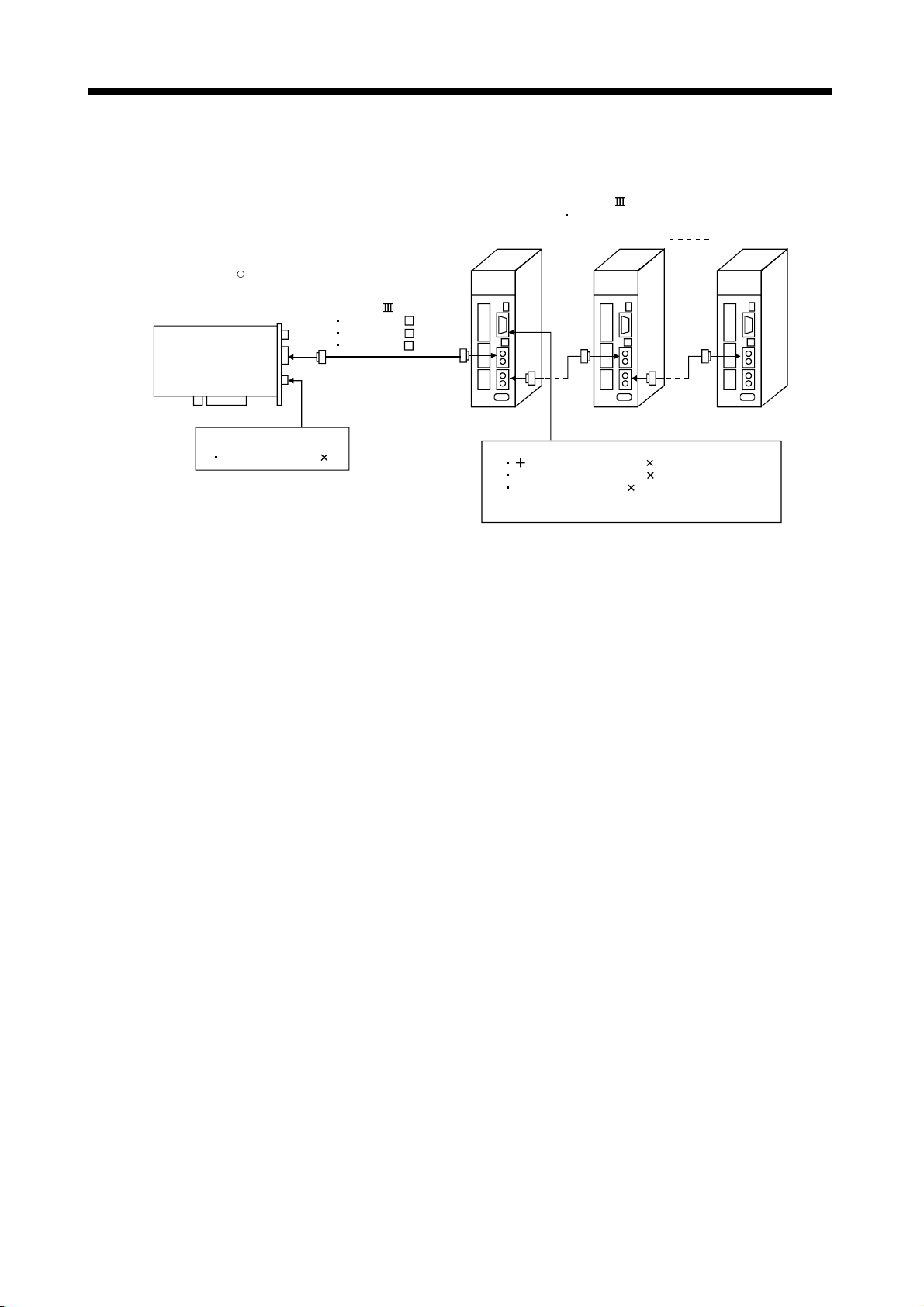
2. SYSTEM CONFIGURATION
2.1.3 MR-MC240 system configuration
SSCNET /H-compatible
Servo amplifier MR-J4-B
Axis 2Axis 1 Axis 20
PCI Express bus
compatible
position board
MR-MC240
R
SSCNET Cable
MR-J3BUS M
USB
SSCNET
EMI
DI signal
Forced stop (EMI 1)
MR-J3BUS M-A
MR-J3BUS M-B
DI signal
side limit switch (LSP 1)
side limit switch (LSN 1)
Proximity dog (DOG 1)
DI signal (LSP, LSN and DOG) from Servo Amplifier
can be input
2 - 3
Page 51

2. SYSTEM CONFIGURATION
2.1.4 MR-MC241 system configuration
SSCNET /H-compatible
Servo amplifier MR-J4-B
Axis 2Axis 1 Axis 20
PCI Express bus
compatible
position board
MR-MC241
SSCNET line 1
SSCNET line 2
R
USB
EMI
DI signal
Forced stop (EMI 1)
SSCNET Cable
MR-J3BUS M
MR-J3BUS M-A
MR-J3BUS M-B
Axis 2Axis 1 Axis 12
DI signal
side limit switch (LSP 1)
side limit switch (LSN 1)
Proximity dog (DOG 1)
DI signal (LSP, LSN and DOG) from Servo Amplifier
can be input
POINT
Refer to Section 4.5.5 to change the number of axes distributed to line 1 and
line 2
2 - 4
Page 52

2. SYSTEM CONFIGURATION
2.2 System configuration equipment
(1) MR-MC2
Part name
Position board
USB cable MR-J3USBCBL3M Position board MR-MC2 host controller
SSCNET
cable
Note 1. =Cable length (015: 0.15m(0.49ft.), 03: 0.3m(0.98ft.), 05: 0.5m(1.64ft.), 1: 1m(3.28ft.), 2: 2m(6.56ft.), 3: 3m(9.84ft.),
5: 5m(16.40ft.), 10: 10m(32.81ft.), 20: 20m(65.62ft.), 25: 25m(82.02ft.), 30: 30m(98.43ft.), 40: 40m(131.23ft.), 50: 50m(164.04ft.)
2. Cable for forced stop input is not attached to the position board. The cable should be made by the customer.
3. Please contact your nearest Mitsubishi sales representative for the cable of less than 30m(98.43ft.).
related module
Model name
(Note 1)
MR-MC210 Up to 20 axes control, Operation cycle 0.22[ms], 0.44[ms], 0.88[ms], PCI bus compatible (Note 2)
MR-MC211 Up to 32 axes control, Operation cycle 0.22[ms], 0.44[ms], 0.88[ms], PCI bus compatible (Note 2)
MR-MC240
MR-MC241
MR-J3BUS
MR-J3BUS M-A
MR-J3BUS M-B
(Note 3)
Up to 20 axes control, Operation cycle 0.22[ms], 0.44[ms], 0.88[ms], PCI Express
(Note 2)
Up to 32 axes control, Operation cycle 0.22[ms], 0.44[ms], 0.88[ms], PCI Express
(Note 2)
• MR-MC2
M
• Standard cord for inside panel 0.15m(0.49ft.), 0.3m(0.98ft.), 0.5m(1.64ft.), 1m(3,28ft.), 3m(9.84ft.)
• MR-MC2
• Standard cable for outside panel 5m(16.40ft.), 10m(32.81ft.), 20m(65.62ft.)
• MR-MC2 MR-J4(W )- B/MR-J4(W )- B MR-J4(W )- B
• Long distance cable 30m(98.43ft.), 40m(131.23ft.), 50m(164.04ft.)
MR-J4(W )- B/MR-J4(W )- B MR-J4(W )- B
MR-J4(W )- B/MR-J4(W )- B MR-J4(W )- B
Description
®
bus compatible
®
bus compatible
(2) Servo amplifier
Part name Model name Description Remarks
MR-J4 series
servo amplifier
MR-J3 series
servo amplifier
MR-J4-
MR-J4- B-RJ
MR-J4W- B For 2-axis type, 3-axis type
MR-J3- B
MR-J3W- B For 2-axis type
MR-J3- B-RJ006 For fully closed control
MR-J3- B-RJ004 For linear servo motor
MR-J3- B-RJ080W For direct drive motor
MR-J3- B Safety For drive safety servo
MR-J3W-0303BN6 For 2-axis type
B
Refer to the servo amplifier
instruction manuals.
(3) Software packages
(a) Utility software
Model name Software package
Position Board Utility2 MRZJW3-MC2-UTL
(b) Servo set-up software package
Model name Software package
MR Configurator2 SW1DNC-MRC2-E
2 - 5
Page 53

2. SYSTEM CONFIGURATION
2.3 Checking serial number and operating system software version
Checking for the serial number of position board and software version are shown below.
2.3.1 Checking serial number
(1) Rating plate
The serial number is printed on the rating plate which is on the position board.
See
SERIAL
MR-MC240
Voyez MR-MC240 mode d'emploi.
MADE IN JAPAN
MITSUBISHI
ELECTRIC
MR-MC240 Instructi on manual.
A21001999
3.3VDC 1.5A
Rating
plate
C
80M1
IND. CONT. EQ.
LISTED
U
L
US
MSIP-REI-MEK-
DATE 2014-02
TC510A875G51
BC370C286H01
PASSED
Serial number
POINT
• When the position board is mounted to the host controller, the serial number
cannot be checked. Take note of the serial number before mounting.
2.3.2 Checking software version
The software version of the position board can be checked on the system program software version (0030h to
003Fh) of system information. System program software version is stored as ASCII code.
0030h
System program
software version
0031h0032h0033h
B
(42h)C(43h)D(44h)-(2Dh)
0034h
0035h
0036h
B
5
(35h)
2
(32h)
(42h)
Software type name
0037h
0038h
W
(57h)
(31h)
101: MR-MC21
0039h
1
0
(30h)
Type name
003Ah
1
(31h)
003Bh
003Ch
003Dh
003Eh
-
A
(41h)
3
(33h)
(2Dh)
Version
Note. In (): ASCII code
: Space
(20h)
003Fh
\0
(00h)
API LIBRARY
• To check the software version, use the sscGetBoardVersion function.
2 - 6
Page 54

2. SYSTEM CONFIGURATION
2.4 Restrictions by the Software's Version
There are restrictions in the function that can be used by the version of the software.
Function/Item name Change details
Digital input/output Addition A1 or later 1.20 or later
Servo amplifier general input/output
Digital output signal control for the
other axes start
Dual port memory exclusive control
Pass position interrupt
Alarm history function
Interface mode
Addition of waiting for SSCNET
response (0009h) to system status
code
Speed-torque control
(interface mode only)
Addition of operation cycle alarm to
system alarms
Addition of position droop to high
speed monitor (interface mode only)
Mark detection function compatible
Change home position return method
while system is running.
Continuous operation to torque control
(automatic operation in standard mode
only)
External forced stop disabled function
Addition
Addition
Addition
Addition
Addition
Addition
Addition
Addition
Addition
Addition
Addition
Addition
Addition
Addition
MR-MC2 MRZJW3-MC2-UTL
A1 or later 1.20 or later
A1 or later 1.20 or later
A1 or later 1.20 or later
A1 or later 1.20 or later
A3 or later 1.50 or later
A3 or later 1.50 or later
A3 or later 1.50 or later
A4 or later 1.60 or later
A4 or later 1.60 or later
A4 or later 1.60 or later
A5 or later 1.70 or later
A5 or later 1.70 or later
A5 or later 1.70 or later
A5 or later 1.70 or later
Version
2 - 7
Page 55

2. SYSTEM CONFIGURATION
MEMO
2 - 8
Page 56

3. INSTALLATION AND WIRING
3. INSTALLATION AND WIRING
3.1 Board installation
This section explains instructions for handling and installation environment of the position board.
3.1.1 Instructions for handling
The following explains instructions for handling.
CAUTION
• Do not touch any connectors while power is ON. Doing so may cause electric shock or
malfunction.
• Do not directly touch any conductive parts and electronic components of the board. Doing so
may cause malfunction or failure of the board.
• Do not disassemble or modify the board. Doing so may cause failure, malfunction, injury, or fire.
• Before handling the board, touch a conducting object such as a grounded metal to discharge the
static electricity from the human body. Failure to do so may cause the board to fail or
malfunction.
• Handle the board in a place where static electricity will not be generated. Failure to do so may
cause a failure or malfunction.
• The board is included in a static electricity preventing vinyl bag. When storing or transporting it,
be sure to put it in the static electricity preventing vinyl bag. Failure to do so may cause a failure
or malfunction.
• Do not drop or apply a strong impact to the board. Doing so may cause a failure or malfunction.
3
3.1.2 Installation environment
For installation of the host controller in which the position board is installed, refer to the manual for the host
controller.
(1) Instructions for board installation environment
Use the board in an environment that meets the general specifications in this manual. Failure to do so may
result in electric shock, fire, malfunction, or damage to or deterioration of the product.
(2) Instructions for host controller installation environment
Always ground the host controller to the protective ground conductor. Failure to do so may cause a
malfunction.
3 - 1
Page 57

3. INSTALLATION AND WIRING
3.2 Connection and disconnection of cable
3.2.1 SSCNET
(1) Precautions for handling the SSCNET
• Do not stamp the SSCNET
• When laying the SSCNET
cable
cable
cable.
cable, be sure to secure the minimum cable bend radius or more. If the bend
radius is less than the minimum cable bend radius, it may cause malfunctions due to characteristic
deterioration, wire breakage, etc.
• For connection and disconnection of SSCNET
Position board
cable, hold surely a tab of cable connector.
1CH
2CH
(2) Connection of SSCNET
• For connection of SSCNET
2CH of position board while holding a tab of SSCNET
• If the cord tip for the SSCNET
cable
cable to the position board, connect it to the SSCNET connector 1CH or
cable connector. Be sure to insert it until it clicks.
cable is dirty, optical transmission is interrupted and it may cause
malfunctions. If it becomes dirty, wipe with a bonded textile, etc. Do not use solvent such as alcohol.
(3) Disconnection of SSCNET
• For disconnection of SSCNET
cable
cable, pull out it while holding a tab of SSCNET cable connector or the
connector.
• After disconnection of SSCNET
cable, be sure to put a cap (attached to position board or servo
amplifier) to the position board and servo amplifier.
• For SSCNET
cable, attach the tube for protection optical cord's end face on the end of connector.
3 - 2
Page 58

3. INSTALLATION AND WIRING
(4) Precautions of SSCNET
SSCNET
cable is made from optical fiber. If optical fiber is added a power such as a major shock, lateral
cable wiring
pressure, haul, sudden bending or twist, its inside distorts or breaks, and optical transmission will not be
available. Especially, as optical fiber for MR-J3BUS
M and MR-J3BUS M-A is made of synthetic resin, it
melts down if being left near the fire or high temperature. Therefore, do not make it touched the part, which
becomes high temperature, such as radiator or regenerative option of servo amplifier, or servo motor.
Be sure to use optical fiber within the range of operating temperature described in this manual.
Read described item of this section carefully and handle it with caution.
(a) Minimum bend radius
Make sure to lay the cable with greater radius than the minimum bend radius. Do not press the cable to
edges of equipment or others. For SSCNET
cable, the appropriate length should be selected with due
consideration for the dimensions and arrangement of position board and servo amplifier. When closing
the door of control panel, pay careful attention for avoiding the case that SSCNET
by the door and the cable bend becomes smaller than the minimum bend radius.
Model name of SSCNET cable Minimum bend radius[mm(inch)]
MR-J3BUS M 25(0.98)
MR-J3BUS M-A
MR-J3BUS M-B
Enforced covering cord : 50 (1.97)
Cord : 25 (0.98)
Enforced covering cord : 50 (1.97)
Cord : 30 (1.18)
cable is hold down
(b) Tension
If tension is added on the SSCNET
external force which concentrates on the fixing part of SSCNET
SSCNET
connector. At worst, the breakage of SSCNET cable or damage of SSCNET connector
cable, the increase of transmission loss occurs because of
cable or the connecting part of
may occur. For cable laying, handle without putting forced tension. (Refer to "APPENDIX 6.1 SSCNET
cables" for the tension strength.)
(c) Lateral pressure
If lateral pressure is added on the SSCNET
stressed, and then transmission loss will increase. At worst, the breakage of SSCNET
occur. As the same condition also occurs at cable laying, do not tighten up SSCNET
cable, the cable itself distorts, internal optical fiber gets
cable may
cable with a thing
such as nylon band (TY-RAP). Do not trample it down or tuck it down with the door of control panel or
others.
(d) Twisting
If SSCNET
cable is twisted, it will become the same stress added condition as when local lateral
pressure or bend is added. Consequently, transmission loss increases, and the breakage of SSCNET
cable may occur at worst.
(e) Disposal
When incinerating optical cable (cord) used for SSCNET
cable, hydrogen fluoride gas or hydrogen
chloride gas which is corrosive and harmful may be generated. For disposal of SSCNET
request for specialized industrial waste disposal services who has incineration facility for disposing
hydrogen fluoride gas or hydrogen chloride gas.
cable,
3 - 3
Page 59

3. INSTALLATION AND WIRING
POINT
• Be sure to connect SSCNET cable with the above connector. If the
connection is mistaken, between the position board and servo amplifier
cannot be communicated.
• Forced removal of the SSCNET
the position board and SSCNET
• After removal of the SSCNET
connector. Otherwise, adhesion of dirt deteriorates in characteristic and it may
cause malfunctions.
• Do not remove the SSCNET
position board and servo amplifier.
Do not see directly the light generated from SSCNET
board or servo amplifier and the end of SSCNET
into eye, may feel something is wrong for eye. (The light source of SSCNET
cable complies with class1 defined in JISC6802 or IEC60825-1.)
• If the SSCNET
pressure, haul, sudden bending or twist, its inside distorts or brakes, and
optical transmission will not be available.
Be sure to take care enough so that the short SSCNET
twist easily.
• Be sure to use the SSCNET
described in this manual. Especially, as optical fiber for MR-J3BUS
MR-J3BUS
the fire or high temperature. Therefore, do not make it touched the part which
becomes high temperature, such as radiator or regenerative option of servo
amplifier, or servomotor.
cable is added a power such as a major shock, lateral
M-A are made of synthetic resin, it melts down if being left near
cable from the position board will damage
cables.
cable, be sure to put a cap on the SSCNET
cable while turning on the power supply of
connector of position
cable. When the light gets
cable is added a
cable within the range of operating temperature
M and
• When laying the SSCNET
radius or more.
• Put the SSCNET
position board with bundle material in order to prevent SSCNET
putting its own weight on SSCNET
When laying cable, the optical cord should be given loose slack to avoid from
becoming smaller than the minimum bend radius, and it should not be twisted.
When bundling the cable, fix and hold it in position by using cushioning such
as sponge or rubber which does not contain migratable plasticizing.
If using adhesive tape for bundling the cable, fire resistant acetate cloth
adhesive tape 570F (Teraoka Seisakusho Co., Ltd) is recommended.
cable in the duct or fix the cable at the closest part to the
cable, be sure to secure the minimum cable bend
cable from
connector.
3 - 4
Page 60

3. INSTALLATION AND WIRING
POINT
• Migratable plasticizer is used for vinyl tape. Keep the MR-J3BUS M, and
MR-J3BUS
characteristic may be affected.
M-A cables away from vinyl tape because the optical
Cable
SSCNET cable Cord Cable
MR-J3BUS M
MR-J3BUS M-A
MR-J3BUS M-B
Optical cord
: Normally, cable is not affected by plasticizer.
: Phthalate ester plasticizer such as DBP and DOP may affect optical
characteristic of cable.
Generally, soft polyvinyl chloride (PVC), polyethylene resin (PE) and fluorine
resin contain non-migratable plasticizer and they do not affect the optical
characteristic of SSCNET
cable. However, some wire sheaths and cable
ties, which contain migratable plasticizer (phthalate ester), may affect
MR-J3BUS
MR-J3BUS
• If the adhesion of solvent and oil to the cord part of SSCNET
M and MR-J3BUS M-A cables (made of plastic). In addition,
M-B cable (made of quartz glass) is not affected by plasticizer.
cable may
lower the optical characteristic and machine characteristic. If it is used such
an environment, be sure to do the protection measures to the cord part.
• When keeping the position board or servo amplifier, be sure to put on a cap
to connector part so that a dirt should not adhere to the end of SSCNET
connector.
• SSCNET
connector to connect the SSCNET cable is put a cap to protect
light device inside connector from dust. For this reason, do not remove a cap
until just before connecting SSCNET
SSCNET
cable, make sure to put a cap.
• Keep the cap and the tube for protecting light cord end of SSCNET
in a plastic bag with a zipper of SSCNET
cable. Then, when removing
cable
cable to prevent them from
becoming dirty.
• When exchanging the position board or servo amplifier, make sure to put a
cap on SSCNET
amplifier for some troubles, make also sure to put a cap on SSCNET
connector. When asking repair of position board or servo
connector. When the connector is not put a cap, the light device may be
damaged at the transit. In this case, exchange and repair of light device is
required.
3 - 5
Page 61

3. INSTALLATION AND WIRING
3.2.2 Forced stop input cable
(1) Precautions for handling the forced stop input cable
• For connection or removal of the forced stop input cable, do it surely while holding a connector of forced
stop input cable.
Position board
Ta b
(2) Connection of the forced stop input cable
• For connection of a forced stop input cable to the position board, connect it surely to an EMI connector of
position board while holding a connector. Be sure to insert it until it clicks.
(3) Removal of the forced stop input cable
• For removal of the forced stop input cable, push a tab and pull out the cable while holding a connector.
POINT
The following handling will damage the position board or forced stop input
cable.
• Forced removal of the forced stop input cable from the position board.
• The forced stop input cable is twined other cables.
• Excessive power is applied at cable laying.
Wire the cable correctly.
3 - 6
Page 62

A
r
4. SYSTEM STARTUP
4. SYSTEM STARTUP
The following explains the preparations and settings for system startup.
4.1 Startup procedures
Check of wiring and ambient environment
Position board setting
Servo amplifier setting
Parameter setting
System startup
Perform operation
Visually check whether the position board and servo amplifier are wired
correctly. Also check the ambient environment.
(Refer to Section 4.2 Check of wiring and ambient environment)
Set board ID by position board ID selection (SW1).
(Refer to Section 4.3 Position board setting)
Set axis No. on the axis selection rotary switch of the servo amplifier.
(Refer to Section 4.4 Servo amplifier setting)
Set parameter initialization (system command code: 0003h).
fter parameter initialization, set the parameters according to the
system for control cycle, control option 1, sensor input option, vendo
ID, and type code. For other parameters, set them according to need.
(Refer to Section 4.5 Parameter setting)
Set start system startup (system command code: 000Ah).
(Refer to Section 4.6 System startup processing)
Then operate where necessary.
4
POINT
• When a test operation is necessary before creating a user program,
parameter settings, system startup, operation and such can be performed
using the test tool attached to the utility software.
4 - 1
Page 63

4. SYSTEM STARTUP
4.2 Check of wiring and ambient environment
(1) Wiring
Refer to "Chapter 3 INSTALLATION AND WIRING".
(2) Cable treatment
The wiring cables should not be strained.
The connector part should not be strained.
(3) Environment
Signal cables and bus of host controller are not shorted by wire offcuts and metallic dust.
4 - 2
Page 64

4. SYSTEM STARTUP
4.3 Position board setting
Board ID is set by board ID selection (SW1) switch of the position board.
(1) Board ID
Board ID and board ID selection switch No. are correlated as shown on the table below. Set board ID so
that it will not be duplicated. If it is duplicated, it may interfere with board identification on the host controller
side.
Board ID selection
Board ID Switch 2 Switch 1
3 ON ON
2 ON OFF
1 OFF ON
0 OFF OFF
The following is a setting example for controlling four position boards.
Bus on host controller
Other company’s
board
Position board
Board ID: 0
Board ID Switch 2 Switch 1
Position board
Board ID: 2
0 OFF OFF
2 ON OFF
1 OFF ON
3 ON ON
Position board
Board ID: 1
Position board
Board ID: 3
POINT
• The board ID may be in no particular order, and can be arbitrarily selected
between 0 to 3.
• No. of connectable position boards vary by bus specifications of the host
controller.
4 - 3
Page 65

4. SYSTEM STARTUP
4.4 Servo amplifier setting
(1) MR-J4(W
Axis No. of MR-J4(W
)- B
)- B is set by the axis selection rotary switch (SW1) and the axis No. auxiliary
setting (SW2) on the servo amplifier.
MR-J4- B
ON
1234
MR-J4W - B
ON
321456
3-digit, 7-segment LED
Axis selection rotary switch
Axis 1 to 20
Note. For when set with the axis No.
auxiliary setting
Axis No. auxiliary setting switch
3-digit, 7-segment LED
Axis selection rotary switch
Axis 1 to 20
Note. For when set with the axis No.
auxiliary setting
Axis No. auxiliary setting switch
Servo amplifier
axis No.
d1 0
d2 1 02
d3 2 03
d4 3 04
d5 4 05
d6 5 06
d7 6 07
d8 7 08
d9 8 09
d10 9 10
d11 A 11
d12 B 12
d13 C 13
d14 D 14
d15 E 15
d16 F 16
d17 0
d18 1 18
d19 2 19
d20 3 20
Axis selection
rotary switch
Axis No. auxiliary
setting switch
ON
OFF
ON
OFF
Servo amplifier display
(3-digit, 7-segment LED)
01
17
4 - 4
Page 66

4. SYSTEM STARTUP
POINT
• For each switch setting, refer to the Servo Amplifier Instruction Manual for
your servo amplifier.
• If the "An axis that has not been mounted exists" (system error E400)
occurred, the axis with wrong axis No. set can be confirmed with "information
concerning axis that is not mounted" (monitor No.0480 to 0482).
• The servo amplifier axis No. and the axis No. to be managed on the position
board are different. For details, refer to Section 4.5.5.
The following is a setting example for controlling six axes (MR-J4using MR-MC211.
Line 1
B) for each line by control cycle 0.88ms
Position board
Line 2
Servo
amplifier
d15
Servo
amplifier
d17
Servo
amplifier
d16 d1 d2 d5 d6
Servo
amplifier
d16 d1 d2 d5 d6
Servo
amplifier
Servo
amplifier
Servo
amplifier
Servo
amplifier
Servo
amplifier
Servo
amplifier
Servo
amplifier
Servo
amplifier
Line 1 Line 2
Servo amplifier
axis No.
d15 E OFF OFF d17 0 OFF ON
d20 3 OFF ON d16 F OFF OFF
d1 0 OFF OFF d1 0 OFF OFF
d2 1 OFF OFF d2 1 OFF OFF
d5 4 OFF OFF d5 4 OFF OFF
d6 5 OFF OFF d6 5 OFF OFF
Axis selection
rotary switch
Axis No. auxiliary
setting switch
3 4 3 4
Servo amplifier
axis No.
Axis selection
rotary switch
Axis No. auxiliary
setting switch
POINT
• The servo amplifier axis No. may be in no particular order, and can be
arbitrarily selected between d1 to d20.
• No. of connectable servo amplifiers vary by control cycle.
4 - 5
Page 67

4. SYSTEM STARTUP
4.5 Parameter setting
After parameter initialization, set the parameters according to the system such as for control cycle and external
signal (sensor) input option.
4.5.1 Parameter initialization
After turning on the position board power, initialize parameter and set before system startup starts.
Position board
Host
controller
3) 1)
Dual port
memory
Parameter
data
(Internal
memory)
Servo
2)
Parameter
initial value
Parameter backup
(Flash ROM)
amplifier
Figure 4.1 Parameter data flow during parameter initialization
Procedure Description Remarks
Confirm system preparation completion (system status code 0001h) Confirmation of system preparation completion
1
To read parameter initial values,
perform the parameter
initialization (system command
2
code: 0003h).
Check the parameter initialization
3
completion (system status code:
0003h).
Write parameter from user program if required 3) in Fig. 4.1
4
To read parameters from the flash
ROM, perform the flash ROM
parameter read (system command
code: 0004h).
Check the flash ROM parameter read
completion (system command code:
0004h).
uses sscGetSystemStatusCode.
1) and 2) in Fig. 4.1
Always initialize parameter or read parameter
from the flash ROM.
Procedure 2 and procedure 3 of parameter
initialization uses the sscResetAllParameter
function.
Parameter writing uses
sscChangeParameter/sscChange2Parameter.
4 - 6
Page 68

4. SYSTEM STARTUP
4.5.2 System option 1 setting
SSCNET communication method and control cycle is set by System option 1 (parameter No.0001).
SSCNET communication method is used for communication between a position board and connected units
such as servo amplifiers and SSCNET
/H method is available.
Control cycle is a cycle in which the position board controls command import, position control, status output,
and communication with servo amplifier and 0.88ms, 0.44ms and 0.22ms are available.
Number of servo amplifier axes which a position board can control is shown below for each control cycle.
(1) For MR-MC210/MR-MC240
(a) When SSCNET communication method is SSCNET
Control cycle
0.88ms 20 axes 20 axes Axis 1 to 20
0.44ms 16 axes 16 axes Axis 1 to 16
0.22ms 8 axes 8 axes Axis 1 to 8
Max. No. of
axes connected
Max. No. of axes
connected for each
/H
Controllable axis No.
line
(2) For MR-MC211/MR-MC241
(a) When SSCNET communication method is SSCNET
Control cycle
0.88ms 32 axes 20 axes Axis 1 to 32
0.44ms 16 axes 16 axes Axis 1 to 16
0.22ms 8 axes 8 axes Axis 1 to 8
Note 1. Do not connect more servo amplifiers than the max. No. of axes connected. When more servo
amplifiers are connected than the max. No. of axes connected, system setting error
(alarm No. 38, detail 01) will occur.
2. Use servo amplifier software version A3 or later when the control cycle is 0.22ms, and the
3-axis servo amplifier MR-J4W3-
Max. No. of
axes connected
B is used.
Max. No. of axes
connected for each
/H
Controllable axis No.
line
4 - 7
Page 69

4. SYSTEM STARTUP
Control cycle settings are imported during system startup (system command code: 000Ah), and cannot be
changed during system running (system status code: 000Ah).
(1) System parameter
Parameter
No.
0001 *SYSOP1 System option 1
0002 *SYSOP2 System option 2
Abbreviation Name Function
00
Control cycle setting
Set the control cycle
0: 0.88ms
1: 0.44ms
2: 0.22ms
SSCNET communication method
Set the SSCNET communication
method.
0: SSCNET /H
(Note) SSCNET communication
method is shared in lines
1 and 2.
00
(2) System information
Axis No. assignment
Set 1 when validating axis No.
assignment. When axis No.
assignment is invalid, axis No. is
automatically assigned.
0: Invalid
1: Valid
Consistency check selection at
system startup
Set whether to perform consistency
check for controlled axes setting at
system startup.
0: Valid
1: Invalid
Address Name Description
0004h Control cycle status 0001h: 0.88ms
0005h
0006h Reserved
0007h
0002h: 0.44ms
0003h: 0.22ms
4 - 8
Page 70

4. SYSTEM STARTUP
4.5.3 System option 2 setting
Set control mode (standard mode or interface mode) by System option 2 (parameter No.0002).
When using interface mode, select "1: Interface mode".
When interface mode is assigned and system is startup, the in interface mode signal (IFMO) turns ON.
Control mode setting is imported during system startup (system command code: 000Ah), and cannot be
changed during system running (system status code: 000Ah).
(1) System parameter
Parameter
No.
0002 *SYSOP2 System
Abbreviation Name Initial value Units
option 2
0000h 0000h
Setting
range
to
1101h
Function
0
Axis No. assignment
Set 1 when validating axis No.
assignment. When axis No.
assignment is invalid, axis No. is
automatically assigned.
0: Invalid
1: Valid
Consistency check selection at
system startup
Set whether to perform consistency
check for controlled axes setting at
system startup.
0: Valid
1: Invalid
Control mode selection
Set the control mode.
0: Standard mode
1: Interface mode
4 - 9
Page 71

4. SYSTEM STARTUP
4.5.4 Control option 1 setting
When controlling servo amplifier, set "1: control" for control axis of control option 1 (parameter No.0200). When
the axis No. is set out of the controllable range, the corresponding axis will be system setting error (alarm No.
38) and cannot be controlled. If the servo amplifier set is in a state where communication cannot be made,
such as not connected or control circuit power is off, the "An axis that has not been mounted exists" (system
error E400) will occur during system startup (system command code: 000Ah).
POINT
• If the "An axis that has not been mounted exists" (system error E400)
occurred, the axis with wrong No. set can be confirmed with "information
concerning axis that is not mounted" (monitor No.0402).
Control axis settings are imported during system startup (system command code: 000Ah), and cannot be
changed during system running (system status code: 000Ah).
(1) Control parameter
Parameter
No.
0200 *OPC1 Control
Abbreviation Name Initial value Units
option 1
0000h 0000h
Setting
range
to
2111h
Function
Control axis
Set 1 when controlling servo
amplifier.
0: Do not control
1: Control
Amplifier-less axis function
Set 1 when not communicating
with servo amplifier.
When setting 1 with control axis,
operation without servo amplifier
(simulation) is available.
0: Invalid
1: Valid
No home position
Set 1 when setting the position at
the time of power on as the home
position. After returning to home
position, the home position will be
the position where home position
return is complete.
0: Invalid
1: Valid
Speed unit
Set the speed command unit.
0: Position command unit / min
1: Position command unit / s
2: r/min
POINT
• When the amplifier-less axis function is valid, the position board simulates the
operations of servo amplifier and operates as if it is connected. Operation can
be checked without connecting the servo amplifier. When the setting is valid,
the position board do not communicate with the servo amplifier.
4 - 10
Page 72

4. SYSTEM STARTUP
4.5.5 Axis No. assignment
With Axis No. assignment, the axis No. (on the position board) can be assigned by the axis No. on the servo
amplifier.
(1) When Axis No. assignment is invalid
When Axis No. assignment is invalid, correspondence between the axis No. on a position board and the
axis No. on a servo amplifier is shown in the following table.
(a) When SSCNET communication method is SSCNET
Servo amplifier
axis No.
Axis
0.88ms 1 2 3 4 5 6 7 8 9 10 11 12 13 14 15 16 17 18 19 20
No.
0.44ms 1 2 3 4 5 6 7 8 9 10 11 12 13 14 15 16 - - - -
0.22ms 1 2 3 4 5 6 7 8 - - - - - - - - - - - -
d1 d2 d3 d4 d5 d6 d7 d8 d9 d10 d11 d12 d13 d14 d15 d16 d17 d18 d19 d20
/H
Line 1
Servo amplifier
axis No.
Axis
0.88ms 21 22 23 24 25 26 27 28 29 30 31 32 - - - - - - - -
No.
0.44ms - -- - - ---------- - - - --
0.22ms - -- - - ---------- - - - --
d1 d2 d3 d4 d5 d6 d7 d8 d9 d10 d11 d12 d13 d14 d15 d16 d17 d18 d19 d20
Line 2
(2) When Axis No. assignment is valid
When Axis No. assignment is valid, the axis Nos. 1 to 32 (on the position board) can be assigned by the
servo amplifier axis Nos. d1 to d20 arbitrarily.
To assign the axis Nos., set the following parameters.
POINT
• To set servo amplifier axis Nos., use the axis No. assignment (parameter
No.0203).
Valid servo amplifier axis Nos. differ depending on the control cycle. Up to 20
axes can be set.
(a) System parameter
Parameter
No.
0002 *SYSOP2 System option 2
Control cycle SSCNET /H
0.88ms 1 to 20
0.44ms 1 to 16
Abbreviation Name Function
0.22ms 1 to 8
0
00
Axis No. assignment selection
Set 1 when validating axis No.
assignment. When axis No.
assignment is invalid, axis No. is
automatically assigned.
0: Invalid
1: Valid
4 - 11
Page 73

4. SYSTEM STARTUP
(b) Control parameter
Parameter
No.
0203 *AXALC Axis No.
Note 1. An axis No. out of the valid range causes the system setting error (alarm No. 38, detail 03).
2. Regardless of the control axis setting (parameter No.0200), set the axis No. so that the axis No. assignment is not duplicated.
3. When Control is set in the control axis setting (parameter No.0200), always set the axis Nos. (1 to 20). When 0 is set, system
Abbreviation Name Initial value Units
0000h 0000h
assignment
(Except for 00: No axis No. assignment) Duplicated axis Nos. cause the system setting error (alarm No. 38, detail 04).
setting error (alarm No. 38, detail 02) will occur.
Setting
range
to
011Fh
Function
0
Servo amplifier axis No.
Set the servo amplifier axis No. to
be assigned to the axis Nos. on the
position board. (Note 1, 2 and 3)
00h: No axis No. assignment
01h to 14h: Axis No.
Example) 0Ah: Axis No. 10
Servo amplifier line No.
Set the servo amplifier line No. to be
assigned to the axis Nos. on the
position board.
0 to 1: Line No.-1
The following is a setting example for controlling six axes for each line.
Line 1
Position board
Line 2
Servo
amplifier
d1
Axis 1
Servo
amplifier
d1
Axis 5d2Axis 6
amplifier
amplifier
Servo
d2
Axis 2
Servo
Servo
amplifier
d3
Axis 3
Servo
amplifier
d3
Axis 7
Servo
amplifier
d4
Axis 4
Servo
amplifier
d4
Axis 8
Servo
amplifier
d5
Axis 10d6Axis 11
Servo
amplifier
d5
Axis 12d6Axis 13
Servo
amplifier
Servo
amplifier
Axis No. 1 2 3 4 5 6 7 8 10 11 12 13
Control
parameter
No.0203
setting
value
Servo
amplifier
axis No.
0001h 0002h 0003h 0004h 0101h 0102h 0103h 0104h 0005h 0006h 0105h 0106h
Line 1
d1
Line 1
d2
Line 1
d3
Line 1
d4
Line 2
d1
Line 2
d2
Line 2
d3
Line 2
d4
Line 1
d5
Line 1
d6
Line 2
d5
Line 2
d6
4 - 12
Page 74

4. SYSTEM STARTUP
4.5.6 Sensor input option setting
External signal (sensor) is connected by setting sensor input options (parameter No.0219).
Parameter
0219 *SOP Sensor input
021A *SLSP Sensor
021B *SLSN Sensor
021C *SDOG Sensor
Abbreviation Name Initial Value Units
No.
options
signal (LSP)
connection
specification
signal (LSN)
connection
specification
signal (DOG)
connection
specification
0000h
0000h
0000h
0000h
Setting
range
0000h to
0304h
0000 to
3FF1h
0000 to
3FF1h
0000 to
3FF1h
Function
0
0
Sensor input system
Set the input system of the sensor
(LSP, LSN, DOG).
0: Not use
1: Driver input
2: Digital input
3: Not connected (does not detect
LSP, LSN, DOG)
4: Dual port memory input
Limit switch signal selection
Set valid / invalid of limit switch.
0: LSP/LSN are valid
1: LSP is valid, LSN is invalid
2: LSP is invalid, LSN is valid
3: LSP/LSN are invalid
Digital input assignment
Set valid/invalid for the digital input
assignment where LSP is
connected.
0: Not assigned
1: Assigned
Digital input number assignment
Set the digital input number where
the LSP is connected.
000h to 3FFh: DI_000 to DI_3FF
Digital input assignment
Set valid/invalid for the digital input
assignment where LSN is
connected.
0: Not assigned
1: Assigned
Digital input number assignment
Set the digital input number where
LSN is connected.
000h to 3FFh: DI_000 to DI_3FF
Digital input assignment
Set valid/invalid for the digital input
assignment where DOG is
connected.
0: Not assigned
1: Assigned
Digital input number assignment
Set the digital input number where
DOG is connected.
000h to 3FFh: DI_000 to DI_3FF
4 - 13
Page 75
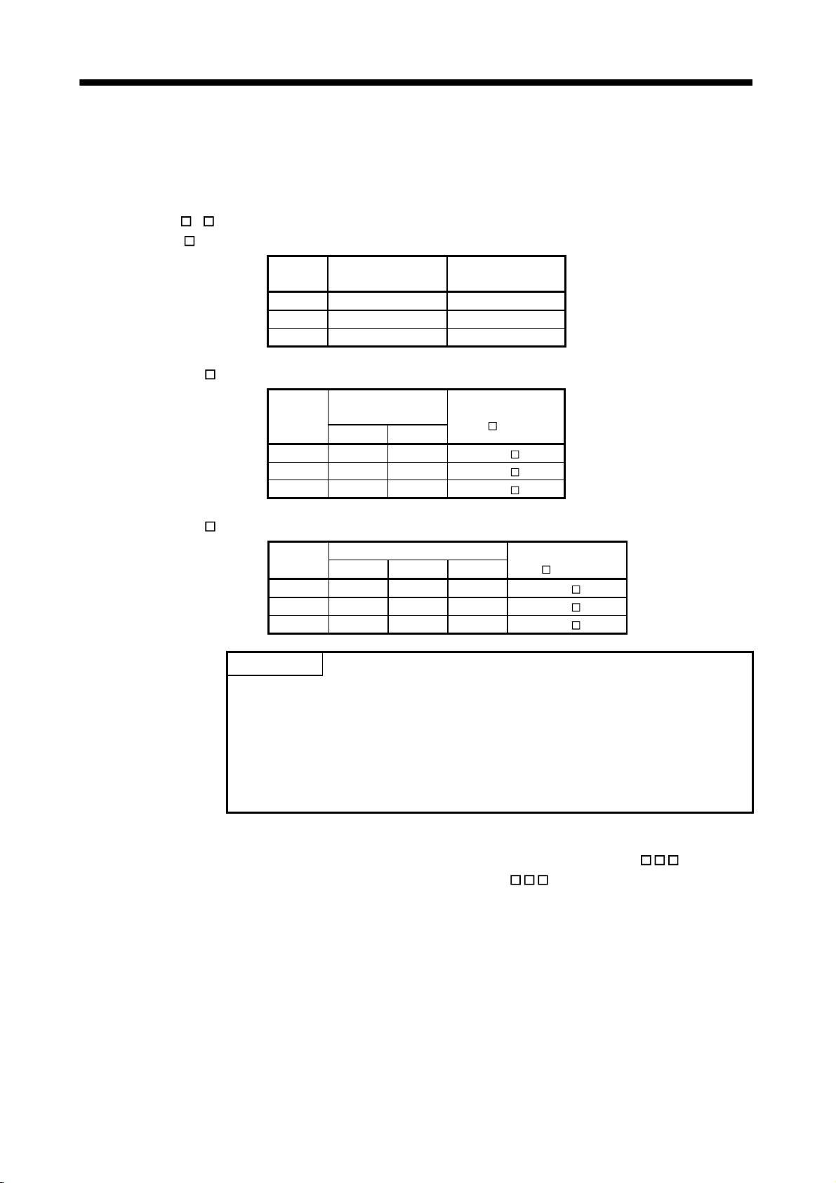
4. SYSTEM STARTUP
(1) When selecting the driver input
When 1 (driver input) is selected as the sensor destination, the sensor (LSP, LSN, DOG) status connected
to the driver (such as a servo amplifier) is imported via SSCNET.
(a) MR-J4(W
1) MR-J4-
)- B is used as a servo amplifier
B
Signal
Name
LSP CN3-2 D11
LSN CN3-12 D12
DOG CN3-19 D13
Destination connector
pin No.
Abbreviation
2) MR-J4W2-
B
Signal
Name
LSP CN3-7 CN3-20 DI1
LSN CN3-8 CN3-21 DI2
DOG CN3-9 CN3-22 DI3
Destination
connector pin No.
A-axis B-axis
Abbreviation
(
: A, B)
3) MR-J4W3-
B
Signal
Name
LSP CN3-7 CN3-20 CN3-1 DI1
LSN CN3-8 CN3-21 CN3-2 DI2
DOG CN3-9 CN3-22 CN3-15 DI3
Destination connector pin No.
A-axis B-axis C-axis
Abbreviation
(
: A, B, C)
POINT
• For sensor connection to the driver, refer to the instruction manual of the
driver.
• If communication error (system error E401 to E407) occurs, sensor (LSP,
LSN, DOG) input status turns off.
• If communication error (system error E400) occurs, the input status of the
corresponding axis turns off.
(2) When selecting the digital input
When 2 (digital input) is selected as the sensor destination, the digital input signal (DI_
the sensor (LSP, LSN, DOG). Specify the digital input signal (DI_
) in the sensor signal connection
) is used as
specification (parameter No.021A to 021C).
Refer to Section 6.26 and 6.27.
(3) When selecting not connected
When 3 (not connected) is selected as the sensor destination, the sensor (LSP/LSN/DOG) is not detected.
Limit switch functions are always invalid. In the home position return using the proximity dog, the position
board operates without detected proximity dog.
4 - 14
Page 76

4. SYSTEM STARTUP
(4) When selecting dual port memory
When 4 (dual port memory input) is selected as the sensor destination,
(LSPC),
side limit switch input signal (LSNC) and proximity dog input signal (DOGC) are imported as
substitutes for sensors.
Address Bit Abbreviation Signal Name
1004 0 ITL Interlock Master
1 RMONR High speed monitor latch
command
2
3
4 LSPC side limit switch input Each axis
5 LSNC side limit switch input Each axis
6 DOGC Proximity dog input Each axis
7 Reserved
Note 1: The above address is the address for the axis 1. For the axis 2 and above, add C0h
for each axis.
Reserved
POINT
• When the sensor input command (LSPC, LSNC, DOGC) is turned on, a
normally-open contact turns on (a normally-closed contact turns off). The
polarity of the limit switch input command is the normally closed contact. The
polarity of the proximity dog input command can be changed by proximity dog
input polarity (parameter No.0240).
side limit switch input signal
When tandem drive
is being used
Each axis
CAUTION
• When "1: driver input" and "2: digital input" are selected as sensor destinations, a delay occurs due
to the communication to detect the signal status. Take the delay time due to communication into
consideration when installing each sensor.
• Communication delay when control cycle is 0.88ms: approx. 2ms
• Communication delay when control cycle is 0.44ms: approx. 1.5ms
• Communication delay when control cycle is 0.22ms: approx. 1.3ms
4 - 15
Page 77

4. SYSTEM STARTUP
4.5.7 Vendor ID and type code setting
Available functions, parameter settings and ranges will vary by servo amplifier type. At the time the
communication with the servo amplifier has started, the position board will perform consistency check between
vendor ID and type code of the servo amplifier connected and the parameter set. If a consistency check error
occurs, driver type code error (system error E405) will be output, therefore set correct vendor ID and type code.
POINT
• If driver type code error (system error E405) occurred, the axis that has set an
incorrect type code can be confirmed with "type code erroneous axis
information" (monitor No.0484 to 0485).
(1) Control parameters
Parameter
No.
021D *VEND Vendor ID Set the vendor ID.
021E *CODE Type code Set the type code.
Abbreviation Name Function
0000: Mitsubishi Electric
1000: MR-J4(W
)- B
4 - 16
Page 78

4. SYSTEM STARTUP
4.6 System startup processing
(1) System startup procedure
After parameter initialization, start system startup before performing operations.
Host
controller
Position board
Dual port
memory
Parameter
data
(Internal
memory)
Parameter
initial value
Parameter backup
(Flash ROM)
1)
Servo
amplifier
Figure 4.2 Parameter data flow during system startup
Procedure Description Remarks
1 The number of seconds passed since 0000hrs, January 1,
1970 is stored in system startup time.
2 Perform the start system startup command (system
command code 000Ah)
3 Confirm the during system running (system status code
000Ah).
The time is used to create data for alarm history function.
When using the API library, the time is automatically set in
the sscSystemStart API function.
1) of Figure 4.2
The position board will start communicating with the servo
amplifier and write the servo parameters according to the
parameters set (refer to Section 4.5.1), and system running
will be in process (system status code: 000Ah).
Start of system startup uses the
sscSetSystemCommandCode function.
Confirmation of during system running uses the
sscSetSystemCommandCode function.
API LIBRARY
• Use the sscSystemStart function to start system startup.
• For a detailed procedure for system startup, refer to the sample programs
(InterruptDrive/AllParamWrite) contained on the utility software.
4 - 17
Page 79

4. SYSTEM STARTUP
(2) Sequence example
Turn Power
ON
sscGetSystemStatusCode function
sscOpen function
Board search and dual port memory access
preparation(open memory access)
Wait for completion of system preparation
(Wait until the system is preparing code 0001h is
set in the system status code)
sscResetAllParameter function
User program Position board
System initialization such as memory check
System preparation completion
(Set "system is preparing code" 0001h in the
system status code)
Parameter initialization command
(set the system command code to 0003h)
Waiting for completion of parameter initialization
(wait until the system status code is set to 0003h)
sscChangeParameter function
Perform writing of parameters as needed.
(data flow 3 in Fig. 4.1)
Setting of system startup time
(set the number of seconds passed since
0000hrs, January 1, 1970)
sscSystemStart function
Start system startup
(set the system command code to 000Ah.)
Start system
startup
Waiting for parameter initialization command
(wait until the system command code is set to
0003h)
Complete parameter initialization
(set the system status code to 0003h)
(data flow 1 in Fig. 4.1)
Waiting for system startup command
(wait until the system command code is set to
000Ah.)
Waiting for SSCNET response
(Set system status code to 0009h)
Initialization of operation functions
Start of communication with servo amplifiers
(data flow 1 in Fig. 4.2)
Wait for completion of system startup
(wait until the system status code is set to 000Ah.)
System startup
completion
Note 1. If an error occurs during system startup, an error code is set in the system status code.
Refer to Section 13.4 concerning error codes.
2. When the system status code does not become 000Ah (an error code is not stored either.), the following is possible: the
SSCNET communication cable is disconnected, the connected equipment is turned off, the SSCNET communication method
(parameter No.0001) is incorrect. The set communication method can be confirmed in SSCNET communication method
(address 0008h).
3. Communication with the axes for which parameter No.0200 control axis is set to "1: control performed" will be implemented,
therefore be sure to set the control axis parameters.
Complete system startup
(set the system status code to 000Ah.)
4 - 18
Page 80

5. OPERATIONAL FUNCTIONS
5. OPERATIONAL FUNCTIONS
POINT
Refer to Chapter 10 for the table bit for each signal.
There are restrictions for the number of axes which can start simultaneously in each operation function and in
start operation using other axes start. When the number of started axes exceeds the maximum number of
simultaneous start axes, start operation will be performed for the rest of axes in the next control cycle or later.
Control cycle Max. No. of simultaneous start axes
0.88ms 16
0.44ms 6
0.22ms 2
POINT
For the start operation of linear interpolation, one group is regarded to consist
of four axes, irrespective of the number of axes in the group.
For the start operation of tandem drive, one group is regarded to consist of
one axis.
Start operation by other axes start takes priority, the other axes start in order.
When the number of axes which is set in start axis designation of the other
axes start table exceeds the maximum number of simultaneous start axes,
other axes start error occurs when the other axes start conditions are fulfilled.
5
The following shows the operation when axes 9 to 14 are started by other axes start by control cycle of 0.44ms,
the other 14 axes are started in normal start operation.
Operation start
axis
Axis01
Axis02
Axis03
Axis04
Axis05
Axis06
Axis07
Axis08
Axis09
Axis10
Axis11
Axis12
Axis13
Axis14
Axis15
Axis16
Axis17
Axis18
Axis19
Axis20
2)
3)
Axis09
Axis10
1)
3)
4)
Axis11
Axis12
Axis13
Axis14
Cycle n + 1Cycle n
Axis01
Axis02
Axis03
Axis04
Axis05
Axis06
Axis09
Axis10
Axis11
Axis12
Axis13
Axis14
Axis01
Axis02
Axis03
Axis04
Axis05
Axis06
Axis07
Axis08
Axis09
Axis10
Axis11
Axis12
Axis13
Axis14
Axis15
Axis16
Axis17
Axis18
Cycle n + 3Cycle n + 2
Axis01
Axis02
Axis03
Axis04
Axis05
Axis06
Axis07
Axis08
Axis09
Axis10
Axis11
Axis12
Axis13
Axis14
Axis15
Axis16
Axis17
Axis18
Axis19
Axis20
: Normal start axis
: Other axes start axis
: After start axis
5 - 1
Page 81

5. OPERATIONAL FUNCTIONS
5.1 JOG operation
5.1.1 Summary
When the movement direction is specified and the start operation signal (ST) input, it starts in the designated
direction and movement continues until the start operation signal (ST) is turned OFF. When the start operation
signal (ST) is turned off, it slows and comes to a stop. JOG operation can be used without completing home
position return. JOG operation can be used without completing home position return (home position return
request (ZREQ) is ON).
sscJogStart function sscJogStop function
Speed
JOG mode (JOG)
Movement direction
(DIR)
Start operation (ST)
Completion of
operation (OPF)
ON
OFF
ON
OFF
ON
OFF
ON
OFF
Start of operation
Stop of operation
5.1.2 Start operation method
Start operation is performed according to the following procedure.
(1) Turn on the JOG operation mode signal (JOG).
(2) Set the manual feed speed, manual feed acceleration constant, and manual feed deceleration constant.
(3) Use the movement direction signal (DIR) to set the movement direction of the axis.
When the movement direction signal (DIR) is OFF, the axis moves in the
the axis moves in the
direction.
direction. And when it is ON,
(4) Turn on the start operation signal (ST).
POINT
The manual feed speed, manual feed acceleration constant, manual feed
deceleration constant, and movement direction signal (DIR) are read at the
leading edge of the start operation signal (ST). It follows that after start
operation, even if there are changes to the data or signal, they are ignored.
API LIBRARY
Use the sscJogStart function to perform procedures (1) to (4) above.
Use the sscJogStop or sscJogStopNoWait functions to perform stop operation.
5 - 2
Page 82

5. OPERATIONAL FUNCTIONS
5.1.3 Resuming operation
When the start operation signal (ST) is turned off, deceleration is started; however, if the start operation signal
(ST) is turned back on while decelerating, it does not completely stop but reaccelerates.
Speed
Start operation (ST)
Completion of
operation (OPF)
ON
OFF
ON
OFF
Start of operation Stop of operation Start of operation
5 - 3
Page 83

5. OPERATIONAL FUNCTIONS
5.2 Incremental feed
5.2.1 Summary
A prescribed feed amount is implemented for each fast start operation signal (FST). The feed amount is
defined using the incremental feed movement amount.
Incremental feed can be used without completing home position return (home position return request (ZREQ)
is ON).
sscWaitIntDriveFin function/
sscGetDriveFinStatus functionsscIncStart function
After moving the movement amount
designated as the incremental feed
Speed
movement amount, it stops.
Incremental feed
mode (S)
Movement direction
(DIR)
Fast Start operation
(FST)
Completion of
operation (OPF)
ON
OFF
ON
OFF
ON
OFFONOFF
ON
OFF
Start of operation
5 - 4
Page 84

5. OPERATIONAL FUNCTIONS
5.2.2 Start operation method
Start operation is performed according to the following procedure.
(1) Turn on the incremental feed mode signal (S).
(2) Set the manual feed speed, manual feed acceleration constant, and manual feed deceleration constant.
(3) Set the incremental feed movement amount.
(4) Use the movement direction signal (DIR) to set the movement direction of the axis.
When the movement direction signal (DIR) is OFF, the axis moves in the
axis moves in the
(5) Turn on the fast start operation signal (FST).
direction.
POINT
The manual feed speed, manual feed acceleration constant, manual feed
deceleration constant, movement direction signal (DIR), and incremental feed
movement are read at the leading edge of the fast start operation signal
(FST). It follows that after start operation, even if there are changes to the
data or signal, they are ignored.
direction and when it is ON, the
Only positive numbers are valid for the incremental feed movement amount.
Movement direction is designated by the movement direction signal (DIR).
API LIBRARY
Use the sscIncStart function to perform procedures (1) to (5) above.
Use the sscGetDriveFinStatus or sscWaitIntDriveFin functions to check
completion of operation.
Use the sscDriveStop or sscDriveStopNoWait functions to perform stop
operation.
5 - 5
Page 85

5. OPERATIONAL FUNCTIONS
5.3 Automatic operation
5.3.1 Summary
Automatic operation (positioning) uses the point table for operation. Position data and feed speed designation
is set in the point table. When the fast start operation signal (FST) is turned on, instructions are executed in
order from the instruction set at the start point number to the end point number. If automatic operation is
started prior to completion of home position return (home position return request (ZREQ) is ON), a home
position return not complete error (operation alarm 90, detail 01) occurs upon starting operation and the
operation stops.
POINT
The first point number for each of the axis point tables is 0000h.
The first point number for each of the axis point tables can be designated
using point number offset. Refer to Section 10.8 concerning point number
offset.
Point table
Position data
[Command units]
Point
4 bytes 4 bytes 2 bytes 2 bytes
0000 2000 2000 20 30 0 0000h 00000000h 0 0
0001 5000 2000 30 50 0 0000h 00000000h 0 0
: : : : : : : : : :
Note. Time specified by the acceleration constant, the deceleration constant and the dwell are rounded off based on the control cycle.
(The value is rounded to the nearest integer.)
For example, the dwell is specified to 10ms with the control cycle of 0.88ms, the time until executing point is completed after the
completion of the point movement is 11 control cycles (approx. 9.778ms).
Feed speed
[Speed units]
(Note)
Acceleration time
constant [ms]
sscAutoStart function
(Note)
Deceleration time
constant [ms]
(Note)
Dwell/pre
dwell [ms]
2 bytes 2 bytes 4 bytes
Auxiliary
command
Other axes
start
specification
sscWaitIntDriveFin function/
sscGetDriveFinStatusfunction
S-curve
ratio [%]
1 bytes 11 bytes
Reserved
Rough match
output limits
Speed
Automatic operation
mode (AUT)
Fast Start operation
(FST)
Completion of
operation (OPF)
(Note)
Rough match (CPO)
Positioning complete
(PF)
Operation point number
Note. The rough match signal (CPO) is determined when the end point is executed. Therefore, it does not turn on when passing points
on the way.
ON
OFF
ON
OFF
ON
OFF
ON
OFF
ON
OFF
Start of operation
01 20
(parameter No.
0230, 0231)
Stops after moving
to the end point
position.
5 - 6
Page 86

5. OPERATIONAL FUNCTIONS
5.3.2 Start operation method
Start operation is performed according to the following procedure.
(1) Set up the point table.
(2) Set the start point number and the end point number.
(3) Turn on the automatic operation mode signal (AUT).
(4) Turn on the fast start operation signal (FST).
POINT
For stoppage of operation mid way, turn on the stop operation signal (STP).
The operation point number can be checked in the operation point number of
the axis status table (same as monitor No.030A).
The point number starts from 0.
The point table is a total of 320 points for all axes. The number of points
distributed to each axis can be adjusted using the point number offset. For
details, refer to Section 10.8.
API LIBRARY
Use the sscSetPointDataEx function to set up point table in (1) above.
Use the sscAutoStart function to perform procedures (2) to (4) above.
Use the sscGetDriveFinStatus or sscWaitIntDriveFin functions to check
completion of operation.
Use the sscDriveStop or sscDriveStopNoWait functions to perform stop
operation.
Use the sscSetPointOffset/sscCheckPointOffset functions to set/get point
number offset.
For a detailed procedure from startup of automatic operation to check
completion of operation, refer to the sample programs
(InterruptDrive/PollingDrive) contained on the utility software.
5 - 7
Page 87

5. OPERATIONAL FUNCTIONS
5.3.3 Auxiliary command
The auxiliary command can be set in the following procedure.
b15
0 0 0
b12
0 0 0
b8 b4
b0
0 0 0
Reserved(bit10 to 15)
Position command system(bit0)
Reserved(bit1 to 3)
Deceleration check system(bit4 to 5)
Speed switching point specification(bit6)
Dwell specification(bit7)
Pass position interrupt specification(bit8)
Continuous operation to torque control
specification(bit9)
(Example) For designation of position command system as 1 (relative position command) and
the deceleration check system as 2 (continue operation), set to "0021h".
(1) Position command system
Select the position data command system.
0: Absolute position command
1: Relative position command
POINT
If the setting of the position command system is incorrect, it causes a point
table setting error (operation alarm 25, detail 01) and operation is stopped.
(a) Absolute position command
Position data is position from the home position.
(b) Relative position command
Position data is the movement distance from the current command position.
(2) Deceleration check system
Designates the point movement completion conditions.
0: In-position stop
1: Smoothing stop
2: Continue operation
POINT
If the setting of the deceleration check system is incorrect, it causes a point
table setting error (operation alarm 25, detail 01) and operation is stopped.
5 - 8
Page 88

5. OPERATIONAL FUNCTIONS
(a) In-position stop
After completion of the command pulse output, if it is in-position, the point movement is completed.
Command speed
Actual speed
When the actual position is within the in-position boundaries, movement to the
next point is started.
Movement to next point
(b) Smoothing stop
After completion of the command pulse output, point movement is complete.
Command speed
Actual speed
If the command is zero, movement to the next point is started.
Movement to next point
(c) Continue operation
After arriving at the position commanded to go to, the speed is changed to the speed commanded for
the next point and movement to the next point is started. The acceleration and deceleration time
constants for changing speeds are set to the acceleration and deceleration time constants of the next
point.
However, continuous operation is not performed under the following conditions.
• When a dwell is set
If there is a dwell defined, after coming to a smoothing stop and completion of the dwell time setting,
movement to the next point is started.
• When there is end point
Operation that is the same as a smoothing stop is performed.
Command speed
Movement to next point
After arriving at the position commanded to go to, speed is changed to the
speed commanded for the next point and movement to the next point is started.
5 - 9
Page 89

t
v
5. OPERATIONAL FUNCTIONS
For the end point of continuous operation, if the position after deceleration stop exceeds the command
position. A selection can be made from the following control option 2 (parameter No.0201).
1) Stop by the alarm
2) After completion of the deceleration stop, return to the command position
3) Stop at the command position
For selection 2), the stop position over-bound signal (POV) is turned on. The stop position over-bound
signal (POV) is turned off at the next start up.
2) After completion of the deceleration stop, return to the command position
Deceleration
time constant
Speed limit
value
Command
speed
3) Stop at the command position
Speed limi
alue
Command
speed
Previous point position
POINT
Next point position
Deceleration
time constant
Previous point position
Next point position
There are times, such as that shown below, where the deceleration position
exceeds the command position. This causes a position exceeded during
positioning (operation alarm 24, detail 01) and operation is stopped.
For when the movement direction is reversed when position of the next
point from the point designated by the deceleration check system under
continuous operation.
For the case where deceleration check system goes from continuous
operation (point n) to smoothing stop (point n
then goes to reverse direction (point n
this order, if point n
1 positioning distance is not satisfied by the necessary
2) even when the point table is in
1) or in-position stop and
deceleration distance from the point n command speed.
5 - 10
Page 90

5. OPERATIONAL FUNCTIONS
(3) Speed switching point specification
If "2: Continue operation" is selected in the deceleration check system, a point where speed change is
completed can be specified.
0: After point switching
1: Before point switching
(a) After point switching
Command speed 2
Command speed 1
Operation point
number
(b) Before point switching
Command speed 2
Command speed 1
Operation point
number
n
n + 1
n
n + 1
POINT
If "1: Before point switching" is specified, the point table (feed speed) of the
next point is imported (read) at start operation or timing when the point
switches next point. If the setting of the point table of the next point is
incorrect, it causes a point table setting error (operation alarm 25, detail 01)
and operation is stopped.
5 - 11
Page 91

5. OPERATIONAL FUNCTIONS
(4) Dwell specification
Specify the system of dwell.
0: Dwell
1: Predwell
POINT
If the setting of the dwell specification is incorrect, it causes a point table
setting error (operation alarm 25, detail 01) and operation is stopped.
(a) Dwell
Specify the time until executing point is completed after the point movement is completed. For the pass
point, after the time specified with dwell has elapsed, the next point starts moving. For the end point,
after the time specified with dwell has elapsed, the completion of operation signal (OPF) turns on.
POINT
The setting range of dwell is 0 to 65535ms.
1) When the deceleration check system is Smoothing stop
Time is counted after the during smoothing of stopping signal (SMZ) turns on. The following shows
the case for the pass point.
Speed
Point 0 is moving.
Point 0 is being executed.
During operation (OP)
During smoothing of
stopping (SMZ)
ON
OFF
ON
OFF
Dwell
Point 1 is moving.
Point 1 is being
executed.
5 - 12
Page 92

5. OPERATIONAL FUNCTIONS
2) When the deceleration check system is In-position stop
Time is counted after the in-position signal (INP) turns on after the during smoothing of stopping
signal (SMZ) turns on. The following shows the case for the end point.
Speed
Dwell
Point 0 is moving.
Point 0 is being executed.
During operation (OP)
During smoothing of
stopping (SMZ)
In-position (INP)
Completion of operation
(OPF)
ON
OFF
ON
OFF
ON
OFF
ON
OFF
3) When the deceleration check system is Continue operation
When dwell is set, the condition of point movement completion is a smoothing stop. Therefore, the
control is the same as when Smoothing stop is set to the decelerate check system.
(b) Predwell
Point starts moving after the time specified with predwell has elapsed.
POINT
The setting of predwell is valid only in the start point. If predwell is set in the
other points, it causes a point table setting error (operation alarm 25, detail
0A) and operation is stopped.
In the initial setting, the setting range of predwell is 0 to 3000ms. If the value
which is out of the range is set, it causes a point table setting error (operation
alarm 25, detail 0A) and operation is stopped.
To remove the limit of the setting range, set 1: 0 to 65535ms to predwell
setting range (parameter No.0206).
5 - 13
Page 93

5. OPERATIONAL FUNCTIONS
CAUTION
If large value is set by mistake, the wait time of axis is long and it may look as if axes did not
operate. In that case, it is dangerous to approach the moving part because axes operate
unexpectedly. Do not approach the moving parts even when axes do not operate while during
operation signal (OP) is on because the axes may operate.
Predwell
Speed
Point 1 is moving.
Point 1 is being
executed.
During operation (OP)
During smoothing of
stopping (SMZ)
Point 0 is moving.
Point 0 is being executed.
ON
OFF
ON
OFF
(5) Pass position interrupt specification
Select valid or invalid for the pass position interrupt.
0: Pass position interrupt invalid
1: Pass position interrupt valid
POINT
This setting in the point data of the start point number is valid only. If the point
data after the start number are set, it causes a point table setting error
(operation alarm 25, detail 0C) and the operation is stopped.
(6) Continuous operation to torque control specification
Select valid or invalid for continuous operation to torque control.
0: Continuous operation to torque control invalid
1: Continuous operation to torque control valid
POINT
• Refer to Section 6.31 for continuous operation to torque control.
5 - 14
Page 94

5. OPERATIONAL FUNCTIONS
5.3.4 Other axes start specification
Set other axes start data number (1 to 32). When the other axes start data number is set, the position board
starts the other axes according to other axes start conditions and operation details of their start data. Up to 2
other axes start data number can be set. For details of other axes start function, refer to Section 6.23.
POINT
If the setting of the other axes start specification is incorrect, it causes a point
table setting error (operation alarm 25, detail 09) and operation is stopped.
5.3.5 S-curve ratio
Perform S-curve acceleration/deceleration for acceleration/deceleration selected in speed options (parameter
No.0220). For automatic operation, this setting is valid regardless of the setting of S-curve ratio (parameter
No.0221).
0: S-curve acceleration/deceleration invalid
1 to 100: S-curve acceleration/deceleration
5 - 15
Page 95

5. OPERATIONAL FUNCTIONS
5.4 Linear interpolation
5.4.1 Summary
Linear interpolation operation has interpolation control performed for the axes set up as a group. This system
enables a maximum of 4 axis interpolation control. When the feed speed and position data are defined in the
point table and the fast start operation signal (FST) is input, all of the axes setup in the group perform linear
interpolation operation. If linear interpolation operation is started prior to completion of home position return
(home position return request (ZREQ) is ON), a home position return not complete error (operation alarm 90,
detail 01) occurs upon starting operation and the operation stops.
Afterwards, the fast start operation signal (FST) is input on a primary axis and other axes are referred to as
auxiliary axes.
sscWaitIntDriveFin function/
sscLinearStart function
Primary axis speed
sscGetDriveFinStatus function
Stops after moving
to the end point
position.
Auxiliary axis speed
Primary axis
linear interpolation
mode signal (LIP)
Auxiliary axis
linear interpolation
mode signal (LIP)
Primary axis
fast Start operation
(FST)
Primary axis
completion of
operation (OPF)
Primary axis
positioning complete
(PF)
Primary axis
operation point number
ON
OFF
ON
OFF
ON
OFF
ON
OFF
ON
OFF
Start of operation
01 20
POINT
The group setting is set using the linear interpolation group (parameter
No.0260). If the group number is set to 0, the axis becomes an independent
axis, making it so linear interpolation operation can not be performed. The
number of groups that can be defined differs with the control cycle and the
maximum number of groups is 8.
Control cycle Valid group number
0.88 ms 1 to 8
0.44 ms 1 to 4
0.22 ms 0
The fast start operation signal (FST) is only to be input on a primary axis.
5 - 16
Page 96

5. OPERATIONAL FUNCTIONS
An example of the feed speed and speed of axis 1 and 2 when each axis is interpolated is shown below.
Linear
interpolation
speed limit
value
Feed speed
Actual
acceleration
time
Acceleration time
constant
Speed for each axis is figured out by dividing feed speed by distance ratio.
Axis 2
End point
Axis 2 speed
Feed speed
1st axis speed
2nd axis speed
Actual
deceleration
time
Deceleration time
constant
Start position
Axis 1 speed
Axis 1
5 - 17
Page 97

5. OPERATIONAL FUNCTIONS
5.4.2 Settings
The following items are defined for performing linear interpolation. Refer to Section 5.3 concerning details for
the point table.
(1) Setting 1: Items set for all axes to be interpolated.
Items Content Remarks
Point table Position data Define setting within maximum moveable limits.
(Maximum moveable limit
Other axes start specification Define the setting when using the other axes start.
Pass position interrupt specification Define the setting when using the pass position
interrupt.
Axis data Start point number
End point number
Axis data (command bit) Linear interpolation mode signal (LIP) Turn on this bin.
Control parameter Linear interpolation group (parameter No.0260) Define the valid group number.
Speed limit value (parameter No.0222, 0223) Defines the speed limit for each axis. Used when
Define the settings such that the number of points
between start and finish is the same for all axes in the
group configuration.
The maximum number of axes that can be defined for
a group is 4.
For tandem drive axes, only the master axis must be
set.
selecting "speed clamp" or "alarm stop" as control
options for excessive speed processing.
999999999)
(2) Setting 2: Items defined for the primary axis (axis where start operation signal (ST) is input)
Items Content Remarks
Point table for primary axis Feed speed
Acceleration time constant (ms)
Deceleration time constant (ms)
Dwell (ms)
Auxiliary command
S-curve ratio [%]
Control parameters for the
primary axis
Speed units (parameter No.0200)
Linear interpolation options (parameter No.0261)
Linear interpolation speed limit value
(parameter No.0262, 0263)
Start up speed (parameter No.0224, 0225)
Speed units multiplication factor (parameter
No.020E, 020F)
The r/min of the units for speed can not be set.
5 - 18
Page 98

5. OPERATIONAL FUNCTIONS
5.4.3 Start operation method
Start operation is performed according to the following procedure.
(1) Define the linear interpolation group, the linear interpolation speed limit, and the linear interpolation options
in the control parameters. The group number is valid during system startup. Other than that it is valid during
writing of parameters.
(2) Set up the point table. At this time, all items are set up for the primary axis and only position data is set up
for auxiliary axes. Settings for other items are invalid.
(3) Set the start point number and end point number for all of the axes in the group configuration.
Define the setting so that the numbers of points for all of the aces are the same.
(4) Turn on the linear interpolation mode signal (LIP) for all of the axes in the group.
(5) Turn on the fast start operation signal (FST) for the primary axis.
POINT
To stop the operation, turn on stop operation signal (STP) of any axis in the
linear interpolation group.
The operation point number can be checked in the operation point number of
the axis status table (same as monitor No.030A).
The point number starts from 0.
The point table is a total of 320 points for all axes. The number of points
distributed to each axis can be adjusted using the point number offset. For
details, refer to Section 10.8.
API LIBRARY
Use the sscSetPointDataEx function to set up point data in (2) above.
Use the sscLinearStart function to perform procedures (3) to (5) above.
Use the sscDriveStop or sscDriveStopNoWait functions to perform stop
operation.
Use the sscGetDriveFinStatus or sscWaitIntDriveFin functions to check
completion of operation.
Use the sscSetPointOffset/sscCheckPointOffset functions to set/get point
number offset.
5 - 19
Page 99

5. OPERATIONAL FUNCTIONS
5.4.4 Processing for exceeding speed limit for each axis
Processing is different concerning exceeding speed limit for each axis depending on the setting for excessive
speed processing (parameter No.0261).
(1) Using a speed clamp
When parameter No.0261 is set to 0, if there is an axis that exceeds the speed limit, other axes grouped
with the axis are also clamped.
The actual acceleration time is the time until the feed speed after clamping is reached.
Original feed speed
Original speed of each axis
Feed speed after clamp
Speed of each axis after clamp
Acrual acceleration time Actual deceleration time
Start operation
(ST)
Operation
alarm
(OALM)
ON
OFF
ON
OFF
(2) For using alarm stop (example for continuous operation point change)
When parameter No.0261 is set to 1, if there is an axis that exceeds the speed limit for point toggling other
than start up or continuous operation, an alarm is set and start up can not be performed.
During continuous operation, if there is an axis that exceeds the speed limit, an alarm is set and
deceleration to a stop is performed.
Point change
Speed limit for each axis
Speed for each axis for next point
Speed for each axis
Actual deceleration time
Start operation
(ST)
Operation alarm
(OALM)
ON
OFF
ON
OFF
5 - 20
Page 100

5. OPERATIONAL FUNCTIONS
(3) No processing
When parameter No.0261 is set to 2, normal operation is continued even if the speed limit is exceeded.
Feed speed
Speed limit for each axis
Start operation
(ST)
Note. This enables operation at the limits of the motor; however, there is the possibility of setting overload or over speed
alarms.
ON
OFF
Speed of each axis
5.4.5 Restrictions
The following restrictions apply concerning use of linear interpolation.
(1) A primary axis linear interpolation start up error (operation alarm 40) occurs for the following.
• If axes that have been set to something besides linear interpolation mode (LIP) are included in the same
group. (operation alarm 40, detail 01)
• If a single group is defined with 5 or more axes. (operation alarm 40, detail 02)
• If a group number that exceeds the valid group number is defined when performing start operation for
linear interpolation. (operation alarm 40, detail 03)
• If the numbers of points defined for axes in the group are different. (operation alarm 40, detail 04)
• If the speed unit (parameter No.0200) is defined to be "2: r/min". (operation alarm 40, detail 05)
(2) A primary axis linear interpolation point data error (operation alarm 41) and an auxiliary axis group error
(operation alarm 16, detail 01) occur for the following.
• If there is an axis within the group whose movement amount exceeds the maximum of 999999999.
(operation alarm 41, detail 01)
• If the speed limit for the group configured axis is exceeded. (operation alarm 41, detail 02)
(If excessive speed processing (parameter No.0261) is defined to be "1: alarm stop".)
(3) If there is an auxiliary axis in operation or has an alarm set upon starting linear interpolation mode, "can't
start linear interpolation auxiliary axis error" (operation alarm 42) occurs on the primary axis.
(4) If an alarm occurs during operation, the axis that caused the error occurs to the particular alarm and the
other axes in the group are set to "group error" (operation alarm 16, detail 01).
(5) If there is an axis such as the axes defined below within the group, a "software limit error" occurs.
• If there is movement from within Software limits to outside the limits. (operation alarm A1, detail 01)
• If there is movement from outside Software limits in the direction of outside the limits. (operation alarm A2,
detail 01)
(6) The command change signal is input to the primary axis. Input of the signal to auxiliary axes is invalid.
• When changing speeds.
• When changing time constants.
• When changing position.
5 - 21
 Loading...