

Page 1

General-Purpose AC Servo
Ethernet Interface
MODEL
MR-JE-_C
SERVO AMPLIFIER
INSTRUCTION MANUAL
(PROFILE MODE)
C
Page 2
Safety Instructions
Please read the instructions carefully before using the equipment.
To use the equipment correctly, do not attempt to install, operate, maintain, or inspect the equipment until
you have read through this Instruction Manual, Installation guide, and appended documents carefully. Do not
use the equipment until you have a full knowledge of the equipment, safety information and instructions.
In this Instruction Manual, the safety instruction levels are classified into "WARNING" and "CAUTION".
WARNING
CAUTION
Note that the CAUTION level may lead to a serious consequence according to conditions.
Please follow the instructions of both levels because they are important to personnel safety.
What must not be done and what must be done are indicated by the following diagrammatic symbols.
Indicates that incorrect handling may cause hazardous conditions,
resulting in death or severe injury.
Indicates that incorrect handling may cause hazardous conditions,
resulting in medium or slight injury to personnel or may cause physical
damage.
Indicates what must not be done. For example, "No Fire" is indicated by .
Indicates what must be done. For example, grounding is indicated by .
In this Instruction Manual, instructions at a lower level than the above, instructions for other functions, and so
on are classified into "POINT".
After reading this Instruction Manual, keep it accessible to the operator.
A - 1
Page 3
1. To prevent electric shock, note the following
WARNING
Before wiring and inspections, turn off the power and wait for 15 minutes or more until the charge lamp
turns off. Otherwise, an electric shock may occur. In addition, when confirming whether the charge lamp
is off or not, always confirm it from the front of the servo amplifier.
Ground the servo amplifier and servo motor securely.
Any person who is involved in wiring and inspection should be fully competent to do the work.
Do not attempt to wire the servo amplifier and servo motor until they have been installed. Otherwise, it
may cause an electric shock.
Do not operate switches with wet hands. Otherwise, it may cause an electric shock.
The cables should not be damaged, stressed, loaded, or pinched. Otherwise, it may cause an electric
shock.
To prevent an electric shock, always connect the protective earth (PE) terminal (marked ) of the servo
amplifier to the protective earth (PE) of the cabinet.
To avoid an electric shock, insulate the connections of the power supply terminals.
2. To prevent fire, note the following
CAUTION
Install the servo amplifier, servo motor, and regenerative resistor on incombustible material. Installing
them directly or close to combustibles will lead to smoke or a fire.
Always connect a magnetic contactor between the power supply and the power supply (L1/L2/L3) of the
servo amplifier, in order to configure a circuit that shuts down the power supply on the side of the servo
amplifier’s power supply. If a magnetic contactor is not connected, continuous flow of a large current may
cause smoke or a fire when the servo amplifier malfunctions.
Always connect a molded-case circuit breaker, or a fuse to each servo amplifier between the power
supply and the power supply (L1/L2/L3) of the servo amplifier, in order to configure a circuit that shuts
down the power supply on the side of the servo amplifier’s power supply. If a molded-case circuit breaker
or fuse is not connected, continuous flow of a large current may cause smoke or a fire when the servo
amplifier malfunctions.
When using the regenerative resistor, switch power off with the alarm signal. Otherwise, a regenerative
transistor malfunction or the like may overheat the regenerative resistor, causing smoke or a fire.
When you use a regenerative option with an MR-JE-40C to MR-JE-100C, remove the built-in
regenerative resistor and wiring from the servo amplifier.
Provide adequate protection to prevent screws and other conductive matter, oil and other combustible
matter from entering the servo amplifier and servo motor.
A - 2
Page 4
3. To prevent injury, note the following
CAUTION
Only the power/signal specified in the Instruction Manual must be supplied/applied to each terminal.
Otherwise, an electric shock, fire, injury, etc. may occur.
Connect cables to the correct terminals. Otherwise, a burst, damage, etc. may occur.
Ensure that polarity (+/-) is correct. Otherwise, a burst, damage, etc. may occur.
The servo amplifier heat sink, regenerative resistor, servo motor, etc., may be hot while the power is on
and for some time after power-off. Take safety measures such as providing covers to avoid accidentally
touching them by hands and parts such as cables.
4. Additional instructions
The following instructions should also be fully noted. Incorrect handling may cause a malfunction, injury,
electric shock, fire, etc.
(1) Transportation and installation
CAUTION
Transport the products correctly according to their mass.
Stacking in excess of the specified number of product packages is not allowed.
Do not hold the lead of the built-in regenerative resistor, cables, or connectors when carrying the servo
amplifier. Otherwise, it may drop.
Install the servo amplifier and the servo motor in a load-bearing place in accordance with the Instruction
Manual.
Do not get on or put heavy load on the product. Otherwise, it may cause injury.
The equipment must be installed in the specified direction.
Leave specified clearances between the servo amplifier and the cabinet walls or other equipment.
Do not install or operate the servo amplifier and servo motor which have been damaged or have any
parts missing.
Do not block the intake and exhaust areas of the servo amplifier. Otherwise, it may cause a malfunction.
Do not drop or apply heavy impact on the servo amplifiers and the servo motors. Otherwise, injury,
malfunction, etc. may occur.
Do not strike the connector. Otherwise, a connection failure, malfunction, etc. may occur.
When you keep or use the equipment, please fulfill the following environment.
Item Environment
Ambient
temperature
Storage -20 °C to 65 °C (non-freezing)
Ambient
humidity
Storage
Ambience Indoors (no direct sunlight), free from corrosive gas, flammable gas, oil mist, dust, and dirt
Altitude 2000 m or less above sea level (Contact your local sales office for the altitude for options.)
Vibration resistance 5.9 m/s2, at 10 Hz to 55 Hz (directions of X, Y and Z axes)
When the product has been stored for an extended period of time, contact your local sales office.
When handling the servo amplifier, be careful about the edged parts such as corners of the servo
amplifier.
Operation 0 °C to 55 °C (non-freezing)
Operation
5 %RH to 90 %RH (non-condensing)
A - 3
Page 5
r
CAUTION
The servo amplifier must be installed in a metal cabinet.
When fumigants that contain halogen materials such as fluorine, chlorine, bromine, and iodine are used
for disinfecting and protecting wooden packaging from insects, they cause malfunction when entering our
products. Please take necessary precautions to ensure that remaining materials from fumigant do not
enter our products, or treat packaging with methods other than fumigation (heat method). Additionally,
disinfect and protect wood from insects before packing products.
To prevent a fire or injury from occurring in case of an earthquake or other natural disasters, securely
install, mount, and wire the servo motor in accordance with the Instruction Manual.
(2) Wiring
CAUTION
Before removing the CNP1 connector of MR-JE-40C to MR-JE-100C, disconnect the lead wires of the
regenerative resistor from the CNP1 connector.
Wire the equipment correctly and securely. Otherwise, the servo motor may operate unexpectedly.
Make sure to connect the cables and connectors by using the fixing screws and the locking mechanism.
Otherwise, the cables and connectors may be disconnected during operation.
Do not install a power capacitor, surge killer, or radio noise filter (optional FR-BIF) on the servo amplifier
output side.
To avoid a malfunction, connect the wires to the correct phase terminals (U/V/W) of the servo amplifier
and servo motor.
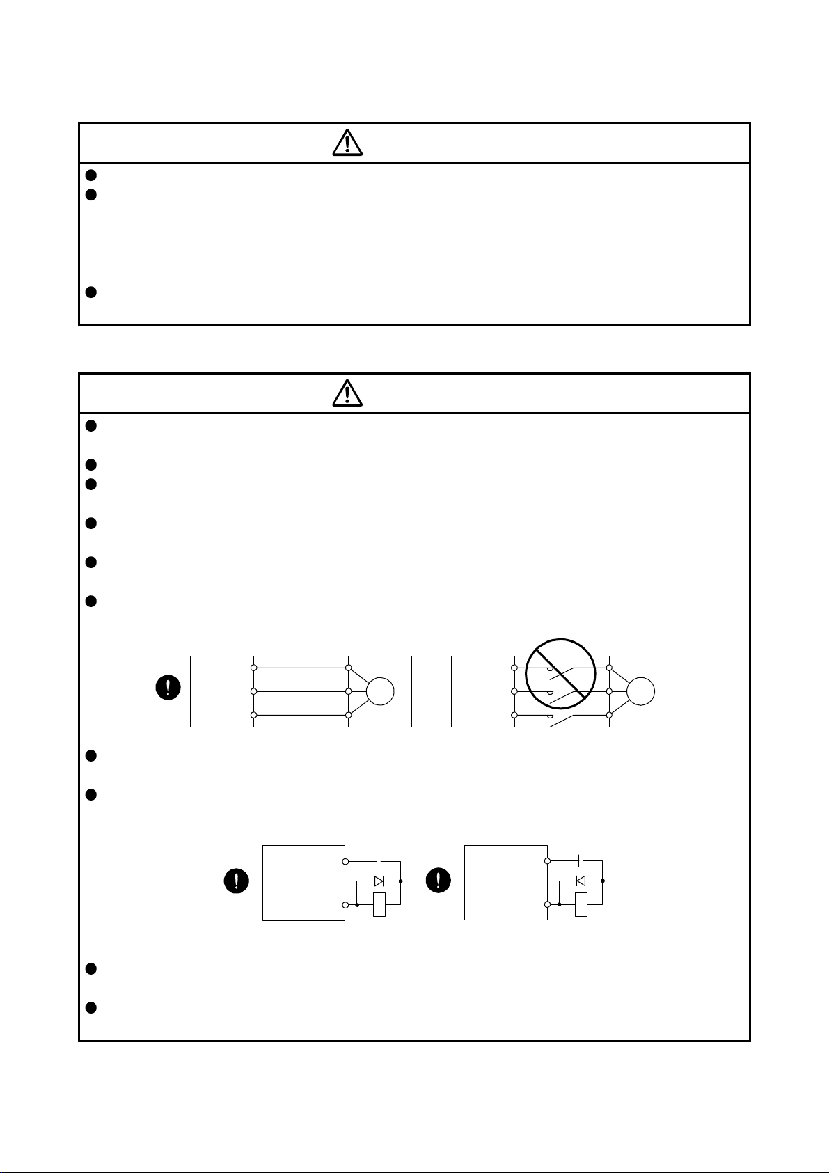
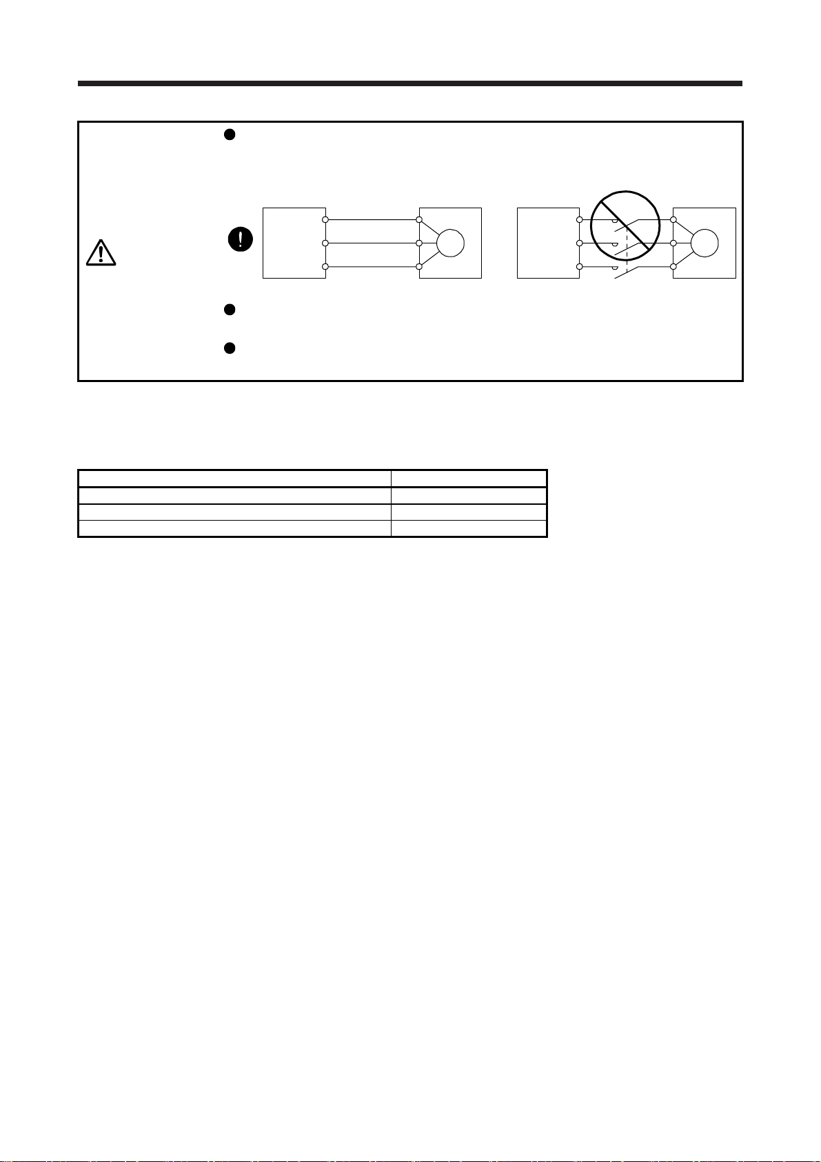
Connect the servo amplifier power output (U/V/W) to the servo motor power input (U/V/W) directly. Do
not let a magnetic contactor, etc. intervene. Otherwise, it may cause a malfunction.
Servo amplifier
U
V
W
Servo motor
U
V
W
Servo motorServo amplifier
U
M
V
W
U
V
W
M
The connection diagrams in this instruction manual are shown for sink interfaces, unless stated
otherwise.
The surge absorbing diode installed to the DC relay for control output should be fitted in the specified
direction. Otherwise, the emergency stop and other protective circuits may not operate.
Servo amplifier
DOCOM
Control output
signal
For sink output interface
24 V DC
RA
Servo amplifie
DOCOM
Control output
signal
For source output interface
24 V DC
RA
When the cable is not tightened enough to the terminal block, the cable or terminal block may generate
heat because of the poor contact. Be sure to tighten the cable with specified torque.
Connecting a servo motor of the wrong axis to U, V, W, or CN2 of the servo amplifier may cause a
malfunction.
A - 4
Page 6
CAUTION
Configure a circuit to turn off EM2 or EM1 when the power supply is turned off to prevent an unexpected
restart of the servo amplifier.
To prevent malfunction, avoid bundling power lines (input/output) and signal cables together or running
them in parallel to each other. Separate the power lines from the signal cables.
(3) Test run and adjustment
CAUTION
When executing a test run, follow the notice and procedures in this instruction manual. Otherwise, it may
cause a malfunction, damage to the machine, or injury.
Before operation, check the parameter settings. Improper settings may cause some machines to operate
unexpectedly.
Never adjust or change the parameter values extremely as it will make operation unstable.
Do not get close to moving parts during the servo-on status.
(4) Usage
CAUTION
When it is assumed that a hazardous condition may occur due to a power failure or product malfunction,
use a servo motor with an external brake to prevent the condition.
For equipment in which the moving part of the machine may collide against the load side, install a limit
switch or stopper to the end of the moving part. The machine may be damaged due to a collision.
Do not disassemble, repair, or modify the product. Otherwise, an electric shock, fire, injury, etc. may
occur. Disassembled, repaired, and/or modified products are not covered under warranty.
Before resetting an alarm, make sure that the run signal of the servo amplifier is off in order to prevent a
sudden restart. Otherwise, it may cause an accident.
Use a noise filter, etc. to minimize the influence of electromagnetic interference. Electromagnetic
interference may be given to the electronic equipment used near the servo amplifier.
Burning or breaking a servo amplifier may cause a toxic gas. Do not burn or break it.
Use the servo amplifier with the specified servo motor.
Correctly wire options and peripheral equipment, etc. in the correct combination. Otherwise, an electric
shock, fire, injury, etc. may occur.
The electromagnetic brake on the servo motor is designed to hold the motor shaft and should not be
used for ordinary braking.
For such reasons as incorrect wiring, service life, and mechanical structure (e.g. where a ball screw and
the servo motor are coupled via a timing belt), the electromagnetic brake may not hold the motor shaft.
To ensure safety, install a stopper on the machine side.
If the dynamic brake is activated at power-off, alarm occurrence, etc., do not rotate the servo motor by an
external force. Otherwise, it may cause a fire.
A - 5
Page 7
(5) Corrective actions
CAUTION
Ensure safety by confirming the power off, etc. before performing corrective actions. Otherwise, it may
cause an accident.
If it is assumed that a power failure, machine stoppage, or product malfunction may result in a hazardous
situation, use a servo motor with an electromagnetic brake or provide an external brake system for
holding purpose to prevent such hazard.
When any alarm has occurred, eliminate its cause, ensure safety, and deactivate the alarm before
restarting operation.
If the molded-case circuit breaker or fuse is activated, be sure to remove the cause and secure safety
before switching the power on. If necessary, replace the servo amplifier and recheck the wiring.
Otherwise, it may cause smoke, fire, or an electric shock.
Provide an adequate protection to prevent unexpected restart after an instantaneous power failure.
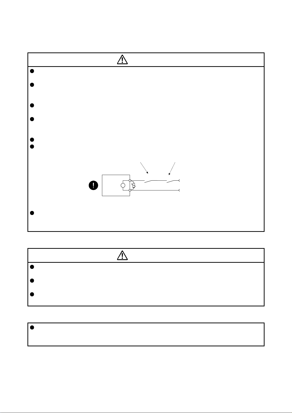
Configure an electromagnetic brake circuit which is interlocked with an external emergency stop switch.
Contacts must be opened when ALM
(Malfunction) or MBR (Electromagnetic
brake interlock) turns off.
Contacts must be opened
with the emergency stop switch.
Servo motor
B
Electromagnetic brake
To prevent an electric shock, injury, or fire from occurring after an earthquake or other natural disasters,
ensure safety by checking conditions, such as the installation, mounting, wiring, and equipment before
switching the power on.
RA
U
24 V DC
(6) Maintenance, inspection and parts replacement
CAUTION
Make sure that the emergency stop circuit operates properly such that an operation can be stopped
immediately and a power is shut off by the emergency stop switch.
It is recommended that the servo amplifier be replaced every 10 years when it is used in general
environment.
When using a servo amplifier whose power has not been turned on for a long time, contact your local
sales office.
(7) General instruction
To illustrate details, the equipment in the diagrams of this Instruction Manual may have been drawn
without covers and safety guards. When the equipment is operated, the covers and safety guards must
be installed as specified. Operation must be performed in accordance with this Instruction Manual.
A - 6
Page 8
DISPOSAL OF WASTE
Please dispose a servo amplifier, battery (primary battery) and other options according to your local laws and
regulations.
EEP-ROM life
The number of write times to the EEP-ROM, which stores parameter settings, etc., is limited to 100,000. If
the total number of the following operations exceeds 100,000, the servo amplifier may malfunction when the
EEP-ROM reaches the end of its useful life.
Write to the EEP-ROM due to parameter setting changes
Write to the EEP-ROM due to device changes
Compliance with global standards
For the compliance with global standards, refer to app. 3 of "MR-JE-_C Servo Amplifier Instruction Manual".
«About the manual»
You must have this Instruction Manual and the following manuals to use this servo. Ensure to prepare
them to use the servo safely.
Relevant manuals
Manual name Manual No.
MELSERVO MR-JE-_C Servo Amplifier Instruction Manual SH(NA)030257ENG
MELSERVO-JE Servo Amplifier Instruction Manual (Troubleshooting) SH(NA)030166ENG
MELSERVO MR-JE-_C Servo Amplifier Instruction Manual (Positioning Mode) SH(NA)030277ENG
MELSERVO MR-JE-_C Servo Amplifier Instruction Manual (Network) SH(NA)030256ENG
MELSERVO HG-KN/HG-SN Servo Motor Instruction Manual SH(NA)030135ENG
MELSERVO EMC Installation Guidelines IB(NA)67310ENG
This Instruction Manual does not describe the following items. Refer to the section of the detailed explanation
field for details. "MR-JE-_C" means "MR-JE-_C Servo Amplifier Instruction Manual".
INSTALLATION MR-JE-_C chapter 2
NORMAL GAIN ADJUSTMENT MR-JE-_C chapter 6
SPECIAL ADJUSTMENT FUNCTIONS MR-JE-_C chapter 7
TROUBLESHOOTING MR-JE-_C chapter 8
DIMENSIONS MR-JE-_C chapter 9
CHARACTERISTICS MR-JE-_C chapter 10
OPTIONS AND PERIPHERAL EQUIPMENT MR-JE-_C chapter 11
ABSOLUTE POSITION DETECTION SYSTEM (Note) MR-JE-_C chapter 12
Note. For the communication-based absolute position transfer system, refer to "MR-JE-_C
Servo Amplifier Instruction Manual (Network)".
Item Detailed explanation
A - 7
Page 9

«Cables used for wiring»
Wires mentioned in this Instruction Manual are selected based on the ambient temperature of 40 °C.
«U.S. customary units»
U.S. customary units are not shown in this manual. Convert the values if necessary according to the
following table.
Quantity SI (metric) unit U.S. customary unit
Mass 1 [kg] 2.2046 [lb]
Length 1 [mm] 0.03937 [inch]
Torque 1 [N•m] 141.6 [oz•inch]
Moment of inertia 1 [(× 10-4 kg•m2)] 5.4675 [oz•inch2]
Load (thrust load/axial load) 1 [N] 0.2248 [lbf]
Temperature N [°C] × 9/5 + 32 N [°F]
A - 8
Page 10

CONTENTS
1. FUNCTIONS AND CONFIGURATION 1- 1 to 1- 4
1.1 Profile mode specification list ........................................................................................................... 1- 2
2. SIGNALS AND WIRING 2- 1 to 2- 6
2.1 I/O signal connection example .......................................................................................................... 2- 3
2.2 Connectors and pin assignment ....................................................................................................... 2- 4
2.3 Signal (device) explanations ............................................................................................................. 2- 5
2.4 Power-on sequence .......................................................................................................................... 2- 5
3. STARTUP 3- 1 to 3- 2
3.1 Startup .............................................................................................................................................. 3- 1
4. PARAMETERS 4- 1 to 4-34
4.1 Parameter list .................................................................................................................................... 4- 1
4.1.1 Basic setting parameters ([Pr. PA_ _ ]) ...................................................................................... 4- 2
4.1.2 Gain/filter setting parameters ([Pr. PB_ _ ]) ............................................................................... 4- 3
4.1.3 Extension setting parameters ([Pr. PC_ _ ]) .............................................................................. 4- 5
4.1.4 I/O setting parameters ([Pr. PD_ _ ]) ......................................................................................... 4- 7
4.1.5 Extension setting 2 parameters ([Pr. PE_ _ ]) ............................................................................ 4- 8
4.1.6 Extension setting 3 parameters ([Pr. PF_ _ ]) ........................................................................... 4-10
4.1.7 Positioning control parameters ([Pr. PT_ _ ]) ............................................................................ 4-11
4.2 Detailed list of parameters ............................................................................................................... 4-13
4.2.1 Basic setting parameters ([Pr. PA_ _ ]) ..................................................................................... 4-13
4.2.2 Extension setting parameters ([Pr. PC_ _ ]) ............................................................................. 4-17
4.2.3 I/O setting parameters ([Pr. PD_ _ ]) ........................................................................................ 4-19
4.2.4 Extension setting 2 parameters ([Pr. PE_ _ ]) ........................................................................... 4-21
4.2.5 Positioning control parameters ([Pr. PT_ _ ]) ............................................................................ 4-23
4.3 Software limit ................................................................................................................................... 4-30
4.4 How to set the electronic gear ......................................................................................................... 4-30
4.4.1 Electronic gear setting for the profile mode .............................................................................. 4-30
4.5 Restrictions on using objects/registers ............................................................................................ 4-33
4.5.1 Restrictions on input devices .................................................................................................... 4-33
4.5.2 Restrictions on objects/registers ............................................................................................... 4-33
5. CiA 402 DRIVE PROFILE 5- 1 to 5- 8
5.1 State machine control of the servo amplifier .................................................................................... 5- 2
5.1.1 Function description ................................................................................................................... 5- 2
5.1.2 Related objects/registers............................................................................................................ 5- 4
5.1.3 Directions for use ....................................................................................................................... 5- 6
5.2 Control mode .................................................................................................................................... 5- 7
5.2.1 Function description ................................................................................................................... 5- 7
5.2.2 Related objects/registers............................................................................................................ 5- 8
1
Page 11

6. SERVO MOTOR DRIVING 6- 1 to 6-44
6.1 Homing mode (hm) ........................................................................................................................... 6- 1
6.1.1 Function description ................................................................................................................... 6- 1
6.1.2 Related objects/registers............................................................................................................ 6- 2
6.1.3 Directions for use ....................................................................................................................... 6- 9
6.2 Profile position mode (pp) ................................................................................................................ 6-32
6.2.1 Function description .................................................................................................................. 6-32
6.2.2 Related objects/registers........................................................................................................... 6-32
6.2.3 Directions for use ...................................................................................................................... 6-35
6.3 Profile velocity mode (pv) ................................................................................................................ 6-36
6.3.1 Function description .................................................................................................................. 6-36
6.3.2 Related objects/registers........................................................................................................... 6-36
6.3.3 Directions for use ...................................................................................................................... 6-39
6.4 Profile torque mode (tq) ................................................................................................................... 6-41
6.4.1 Function description .................................................................................................................. 6-41
6.4.2 Related objects/registers........................................................................................................... 6-41
6.4.3 Directions for use ...................................................................................................................... 6-43
7. APPLICATION OF FUNCTIONS 7- 1 to 7- 2
7.1 Infinite feed function .......................................................................................................................... 7- 1
2
Page 12

1. FUNCTIONS AND CONFIGURATION
1. FUNCTIONS AND CONFIGURATION
This instruction manual describes the items required for using the MR-JE-_C servo amplifier in the profile
mode. For details of the objects/registers and communication, refer to "MR-JE-_C Servo Amplifier Instruction
Manual (Network)".
The items shown in the following table are the same with the contents of "MR-JE-_C Servo Amplifier
Instruction Manual”. For details, refer to each section indicated in the detailed explanation field. "MR-JE-_C"
means "MR-JE-_C Servo Amplifier Instruction Manual".
Combinations of servo amplifiers and servo motors MR-JE-_C section 1.4
Function list MR-JE-_C section 1.5
Model designation MR-JE-_C section 1.6
Structure (parts identification) MR-JE-_C section 1.7
Configuration including peripheral equipment MR-JE-_C section 1.8
Item Detailed explanation
1 - 1
Page 13

1. FUNCTIONS AND CONFIGURATION
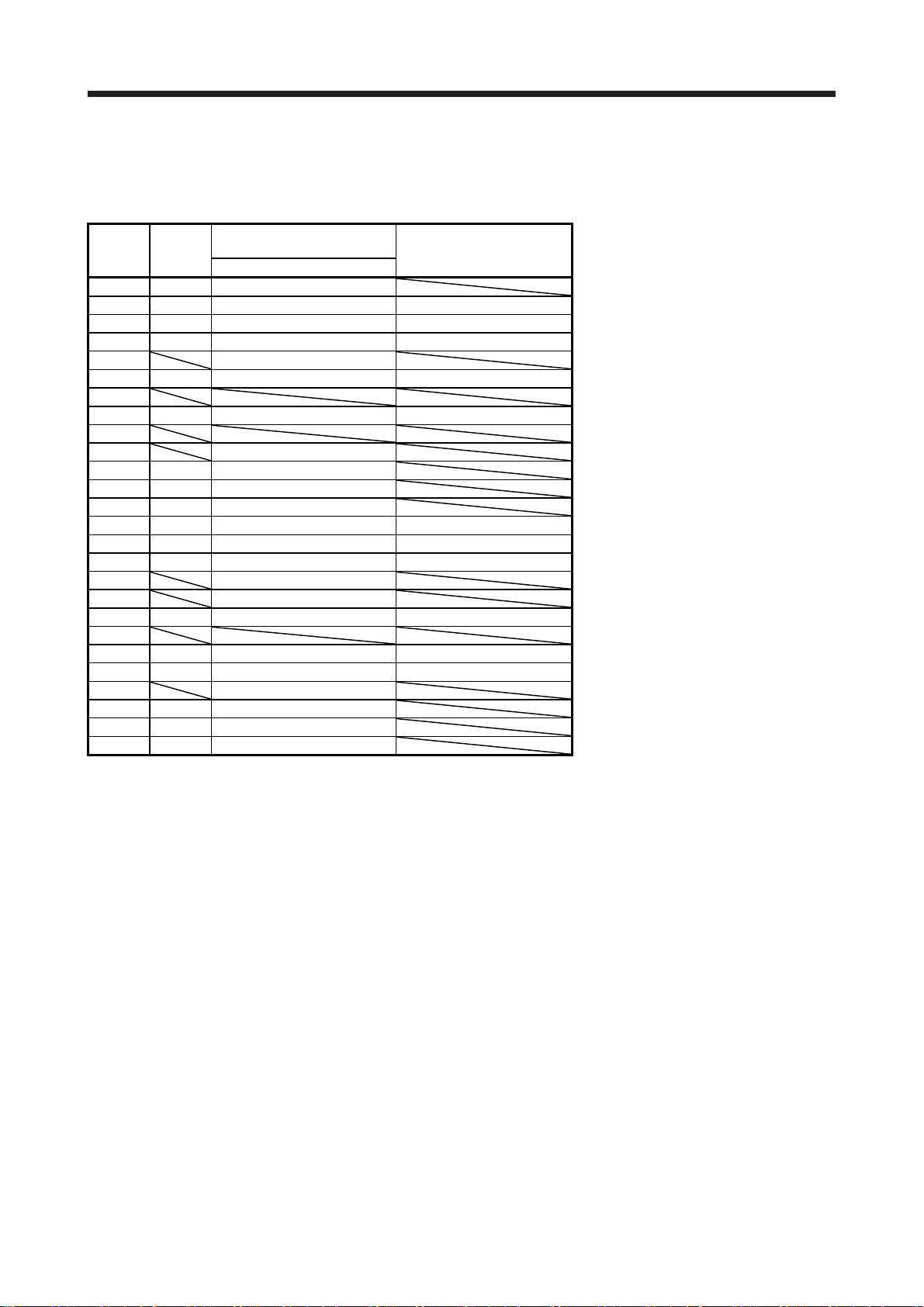
1.1 Profile mode specification list
Only the specifications of the profile mode are listed here. For other specifications, refer to section 1.3 of
"MR-JE-_C Servo Amplifier Instruction Manual".
Profile mode
Profile
position mode
Profile
velocity mode
Profile torque
mode
Data set type The current position is set as the home position.
Stopper type
Home position
Homing mode
Homing on positive
Homing on negative
Item Description
Servo amplifier model MR-JE-_C
Command position range
Command multiplication Electronic gear A/B multiple, A: 1 to 16777215, B: 1 to 16777215, 1/27649 < A/B < 8484
In-position range setting 0 pulse to ±65535 pulses (command pulse unit)
Error excessive ±3 revolutions
Torque limit Set with parameters or objects/registers.
Command speed range -21474836.48 r/min to 21474836.47 r/min (Clamped at the permissible speed)
Torque limit Set with parameters or objects/registers (Clamped at the maximum torque).
Command torque range -3276.8% to 3276.7% (Clamped at the maximum torque)
Speed limit Set with parameters or objects/registers (Clamped at the permissible speed).
Manufacturer-specific
Dog type
(Rear end detection,
Z-phase reference)
Count type
(Front end detection,
Z-phase reference)
(Stopper position
reference)
ignorance
(servo-on position as
home position)
Dog type
(Rear end detection,
rear end reference)
Count type
(Front end detection,
front end reference)
Dog cradle type
Dog type last Z-phase
reference
Dog type front end
reference
Dogless Z-phase
reference
CiA 402 type
Homing on positive
home switch and index
pulse
(method 3)
home switch and index
pulse
(method 4)
home switch and index
pulse
(method 5)
Deceleration starts at the front end of the proximity dog. After the rear end is passed, the position
specified by the first Z-phase signal, or the position of the first Z-phase signal shifted by the specified
home position shift distance is used as the home position. If the stroke end is detected during home
position return, the direction of movement is reversed.
At the front end of the proximity dog, deceleration starts. After the front end is passed, the position
specified by the first Z-phase signal after the set distance or the position of the Z-phase signal shifted
by the set home position shift distance is set as a home position. If the stroke end is detected during
home position return, the direction of movement is reversed.
A workpiece is pressed against a mechanical stopper, and the position where it is stopped is set as
the home position. If the stroke end is detected during home position return, [AL. 90 Home position
return incomplete warning] occurs.
The current position at servo-on is set as a home position. A home position can be set without
switching to the home position return mode (Homing Mode).
Deceleration starts from the front end of the proximity dog. After the rear end is passed, the position
is shifted by the travel distance after proximity dog and the home position shift distance. The position
after the shifts is set as the home position. If the stroke end is detected during home position return,
the direction of movement is reversed.
Deceleration starts from the front end of the proximity dog. The position is shifted by the travel
distance after proximity dog and the home position shift distance. The position after the shifts is set
as the home position. If the stroke end is detected during home position return, the direction of
movement is reversed.
A position, which is specified by the first Z-phase signal after the front end of the proximity dog is
detected, is set as the home position. If the stroke end is detected during home position return, the
direction of movement is reversed.
After the front end of the proximity dog is detected, the position is shifted away from the proximity dog
in the reverse direction. Then, the position specified by the first Z-phase signal or the position of the
first Z-phase signal shifted by the home position shift distance is used as the home position. If the
stroke end is detected during home position return, the direction of movement is reversed.
Starting from the front end of the proximity dog, the position is shifted by the travel distance after
proximity dog and the home position shift distance. The position after the shifts is set as the home
position. If the stroke end is detected during home position return, the direction of movement is
reversed.
The position specified by the first Z-phase signal, or the position of the first Z-phase signal shifted by
the home position shift distance is used as the home position. If the stroke end is detected during
home position return, [AL. 90 Home position return incomplete warning] occurs.
Same as the dog type last Z-phase reference home position return. Note that if the stroke end is
detected during home position return, [AL. 90 Home position return incomplete warning] occurs.
Same as the dog cradle type home position return. Note that if the stroke end is detected during
home position return, [AL. 90 Home position return incomplete warning] occurs.
Same as the dog type last Z-phase reference home position return. Note that if the stroke end is
detected during home position return, [AL. 90 Home position return incomplete warning] occurs.
Setting range of feed length: -999999 to 999999 [pulse],
Setting range of rotation angle: -360.000 to 360.000 [degree]
Set with objects/registers.
1 - 2
Page 14

1. FUNCTIONS AND CONFIGURATION
Profile mode
Homing on home
Homing without index
Homing without index
Homing mode
Homing without index
Homing without index
Homing on index pulse
Homing on index pulse
Homing on current
Homing on current
Item Description
CiA 402 type
Homing on negative
home switch and index
pulse
(method 6)
Homing on home
switch and index pulse
(method 7)
Homing on home
switch and index pulse
(method 8)
Homing on home
switch and index pulse
(method 11)
switch and index pulse
(method 12)
pulse (method 19)
Homing without index
pulse (method 20)
pulse (method 21)
Homing without index
pulse (method 22)
pulse (method 23)
Homing without index
pulse (method 24)
pulse (method 27)
Homing without index
pulse (method 28)
(method 33)
(method 34)
position (method 35)
position (method 37)
Same as the dog cradle type home position return. Note that if the stroke end is detected during
home position return, [AL. 90 Home position return incomplete warning] occurs.
Same as the dog type last Z-phase reference home position return.
Same as the dog cradle type home position return.
Same as the dog type last Z-phase reference home position return. The direction of rotation is
opposite to that of the method 7.
Same as the dog cradle type home position return. The direction of rotation is opposite to that of the
method 8.
Same as the dog type front end reference home position return. Note that if the stroke end is
detected during home position return, [AL. 90 Home position return incomplete warning] occurs.
Although this type is the same as the dog cradle type home position return, the stop position is not on
the Z-phase. Starting from the front end of the dog, the position is shifted by the travel distance after
proximity dog and the home position shift distance. The position after the shifts is set as the home
position. If the stroke end is detected during home position return, [AL. 90 Home position return
incomplete warning] occurs.
Same as the dog type front end reference home position return.
Although this type is the same as the dog cradle type home position return, the stop position is not on
the Z-phase. Starting from the front end of the dog, the position is shifted by the travel distance after
proximity dog and the home position shift distance. The position after the shifts is set as the home
position.
Although this type is the same as the dogless Z-phase reference home position return, the creep
speed is applied as the movement start speed.
Although this type is the same as the dogless Z-phase reference home position return, the creep
speed is applied as the movement start speed.
The current position is set as the home position. This type can be executed not in the Operational
enabled state.
The current position is set as the home position. This type can be executed not in the Operational
enabled state.
1 - 3
Page 15

1. FUNCTIONS AND CONFIGURATION
MEMO
1 - 4
Page 16
2. SIGNALS AND WIRING
r
2. SIGNALS AND WIRING
Any person who is involved in wiring should be fully competent to do the work.
Before wiring, turn off the power and wait for 15 minutes or more until the charge
lamp of the servo amplifier is off. Otherwise, an electric shock may occur. In
addition, when confirming whether the charge lamp is off or not, be sure to look at
the lamp from the front of the servo amplifier.
WARNING
CAUTION
Ground the servo amplifier and servo motor securely.
Do not attempt to wire the servo amplifier and servo motor until they have been
installed. Otherwise, it may cause an electric shock.
The cables should not be damaged, stressed, loaded, or pinched. Otherwise, it
may cause an electric shock.
To avoid an electric shock, insulate the connections of the power supply
terminals.
Before removing the CNP1 connector from MR-JE-40C to MR-JE-100C,
disconnect the lead wires of the regenerative resistor from the CNP1 connector.
Wire the equipment correctly and securely. Otherwise, the servo motor may
operate unexpectedly, resulting in injury.
Connect cables to the correct terminals. Otherwise, a burst, damage, etc., may
occur.
Ensure that polarity (+/-) is correct. Otherwise, a burst, damage, etc., may occur.
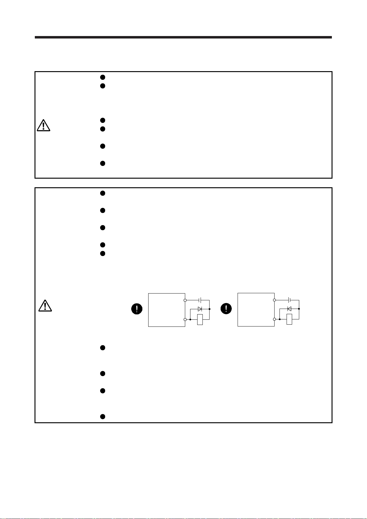
The surge absorbing diode installed to the DC relay for control output should be
fitted in the specified direction. Otherwise, the converter unit and the drive unit will
malfunction and will not output signals, disabling the emergency stop and other
protective circuits.
Servo amplifier
DOCOM
Control output
signal
For sink output interface
24 V DC
RA
Servo amplifie
Control output
signal
For source output interface
DOCOM
24 V DC
RA
Use a noise filter, etc., to minimize the influence of electromagnetic interference.
Electromagnetic interference may affect the electronic equipment used near the
servo amplifier.
Do not install a power capacitor, surge killer or radio noise filter (optional FR-BIF)
with the power line of the servo motor.
When using the regenerative resistor, shut the power off with an alarm signal.
Otherwise, a transistor fault or the like may overheat the regenerative resistor,
causing a fire.
Do not modify the equipment.
2 - 1
Page 17
2. SIGNALS AND WIRING
Connect the servo amplifier power output (U/V/W) to the servo motor power input
(U/V/W) directly. Do not connect a magnetic contactor and others between them.
Otherwise, it may cause a malfunction.
Servo motor
U
V
W
Servo motorServo amplifier
U
M
V
W
U
V
M
W
CAUTION
Servo amplifier
U
V
W
Connecting a servo motor of the wrong axis to U, V, W, or CN2 of the servo
amplifier may cause a malfunction.
Before wiring, switch operation, etc., eliminate static electricity. Otherwise, it may
cause a malfunction.
The items shown in the following table are the same with the contents of "MR-JE-_C Servo Amplifier
Instruction Manual”. For details, refer to each section indicated in the detailed explanation field. "MR-JE-_C"
means "MR-JE-_C Servo Amplifier Instruction Manual".
Item Detailed explanation
Connection example of power circuit MR-JE-_C section 3.1
Explanation of power supply system MR-JE-_C section 3.3
Signal (device) explanations MR-JE-_C section 3.5
2 - 2
Page 18
2. SIGNALS AND WIRING
A
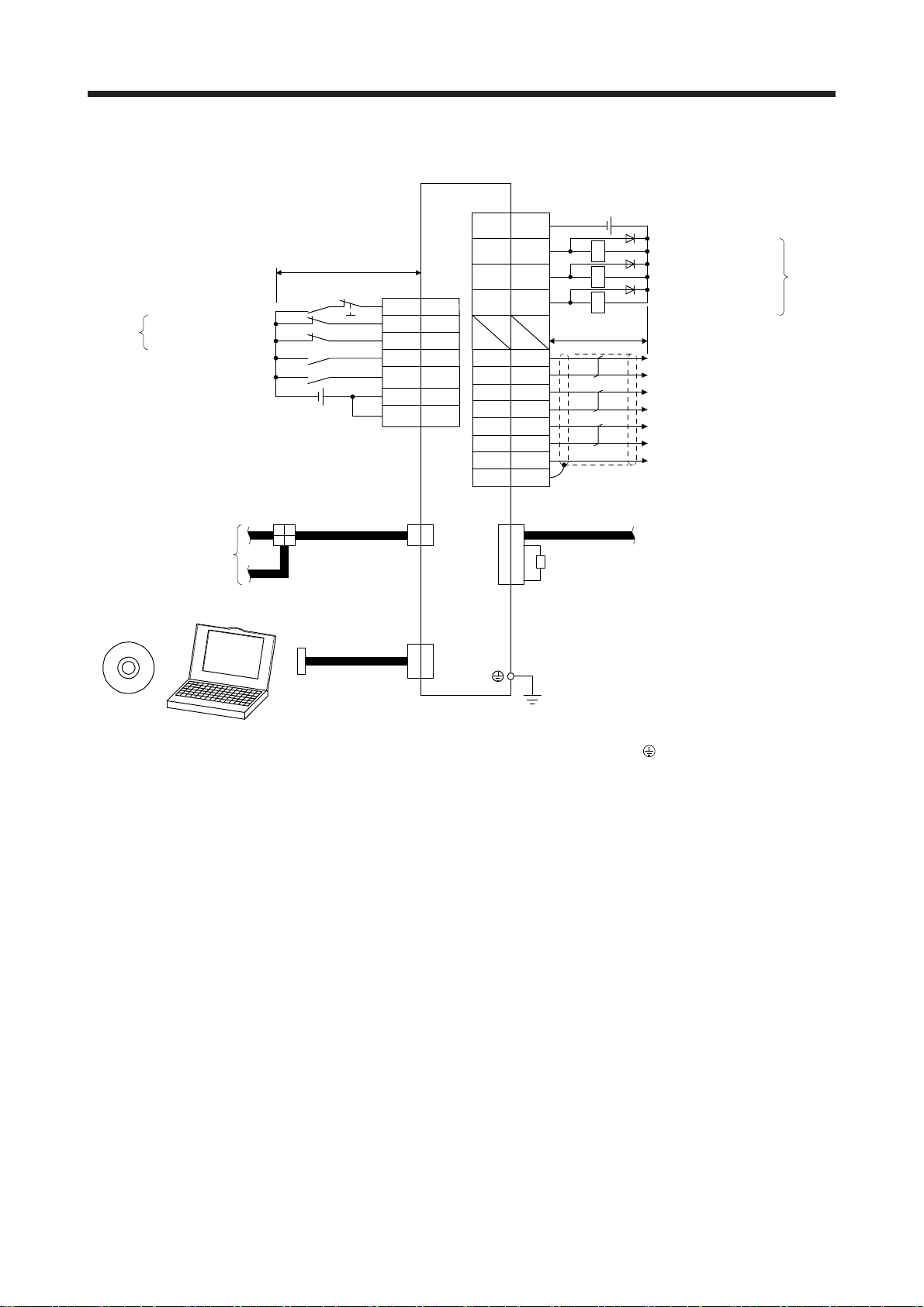
2.1 I/O signal connection example
Servo amplifier
Forced stop2 (Note 3)
Forward rotation
(Note 5)
CC-Link IE Field Network
Basic, SLMP or Modbus/
TCP
(Note 10, 12, 13)
(Note 7)
MR Configurator2
stroke end
Reverse rotation
stroke end
Proximity dog
Touch probe 1
Personal
computer
+
(Note 8)
Power supply
(Note 4, 11)
Switching
hub
10 m or less
24 V DC
Ethernet cable
USB cable
(option)
EM2
LSP
LSN
DOG
TPR1
DICOM
OPC
CN3
17
15 ALM
CN3
1
3
4
2
6
(Note 15)
5
18
(Note 15)
CN1 CN6
CN5
22 INP
13 LZ
26
11 LA
24 LAR
12 LB
25 LBR
23 LG
Plate
DOCOM
LZR
SD
(Note 1)
24 V DC (Note 4, 11)
(Note 2)
RA1
RA2
RA3
10 m or less
(Note 14)
Malfunction (Note 6)
Encoder Z-phase pulse
(open collector)
In-position
Encoder Z-phase pulse
(differential line driver)
Encoder A-phase pulse
(differential line driver)
Encoder B-phase pulse
(differential line driver)
Control common
Modbus RTU
(Note 10, 12, 13)
(Note 9)16 OP
Note 1. To prevent an electric shock, be sure to connect the protective earth (PE) terminal (marked ) of the servo amplifier to the
protective earth (PE) of the cabinet.
2. Connect the diode in the correct direction. If it is connected reversely, the servo amplifier will malfunction and will not output
signals, disabling EM2 (Forced stop 2) and other protective circuits.
3. The forced stop switch (normally closed contact) must be installed.
4. Supply 24 V DC ± 10% to interfaces from outside. The total current capacity of these power supplies must be 300 mA or lower.
300 mA is the value applicable when all I/O signals are used. The current capacity can be decreased by reducing the number
of I/O points. Refer to section 3.9.2 (1) of "MR-JE-_C Servo Amplifier Instruction Manual" that gives the current value
necessary for the interface. The illustration of the 24 V DC power supply is divided between input signal and output signal for
convenience. However, they can be configured by one.
5. When starting operation, always turn on EM2 (Forced stop 2), LSP (Forward rotation stroke end) and LSN (Reverse rotation
stroke end) (normally closed contact).
6.
LM (Malfunction) turns on in normal alarm-free condition (normally closed contact). When this signal is switched off (at
occurrence of an alarm), the output of the programmable controller should be stopped by the sequence program.
7. Use SW1DNC-MRC2-_. MR-JE-_C Servo Amplifier Instruction Manual section 11.4
8. Configure a circuit to turn off EM2 when the power is turned off to prevent an unexpected restart of the servo amplifier.
9. You can change devices of these pins with [Pr. PD30], [Pr. PD31], [Pr. PD32], and [Pr. PD38].
10. For communication function, refer to the "MR-JE-_C Servo Amplifier Instruction Manual (Network)”.
11. This diagram shows sink I/O interface.
12. Modbus/TCP can be used on servo amplifiers with software version A3 or later. Modbus RTU can be used on servo amplifiers
with software version A4 or later.
13. Ethernet communication (CC-Link IE field network Basic, SLMP and Modbus/TCP) and RS-485 communication (Modbus RTU)
are exclusively independent functions. Only the communication function selected in [Pr. PN08] "Select communication
function" can be used.
14. If this servo amplifier is the last axis, connect a 150 Ω resistor between DA and DB, and terminate the servo amplifier. For
details, refer to the "MR-JE-_C Servo Amplifier Instruction Manual (Network)”.
15. When CN3-6 pin is used as the input device of sink interface, supply + of 24 V DC to CN3-18 pin (OPC: power input for opencollector sink interface).
2 - 3
Page 19
2. SIGNALS AND WIRING
2.2 Connectors and pin assignment
For the pins which are given parameters in the related parameter column, their devices can be changed
using those parameters.
Pin No.
1 I EM2
2 I DOG PD07
3 I LSP PD10
4 I LSN PD13
5 DICOM
6 I TPR1 (Note 5) PD25
7
8 I (Note 3) PD16
9
10 LG
11 O LA
12 O LB
13 O LZ
14 O RD PD29
15 O ALM PD30
16 O OP PD31/PD38
17 DOCOM
18 OPC
19 I (Note 4) PD28
20
21 I (Note 3) PD19
22 O INP PD32
23 LG
24 O LAR
25 O LBR
26 O LZR
I/O
(Note 1)
Note 1. I: input signal, O: output signal
2. pp: Profile position mode, pv: Profile velocity mode, tq: Profile torque mode
3. Input devices are not assigned by default. Assign the input devices with [Pr. PD16] and [Pr. PD19] as necessary.
4. Input devices are not assigned by default. When using CN3-19 pin as the input device of sink interface, assign the device with
[Pr. PD28] as necessary. In addition, supply + of 24 V DC to CN3-18 pin (OPC: power input for open-collector sink interface).
5. When CN3-6 pin is used as the input device of sink interface, supply + of 24 V DC to CN3-18 pin (OPC: power input for open-
collector sink interface).
I/O signals in control modes
(Note 2)
pp/pv/tq
Related parameter
2 - 4
Page 20
2. SIGNALS AND WIRING
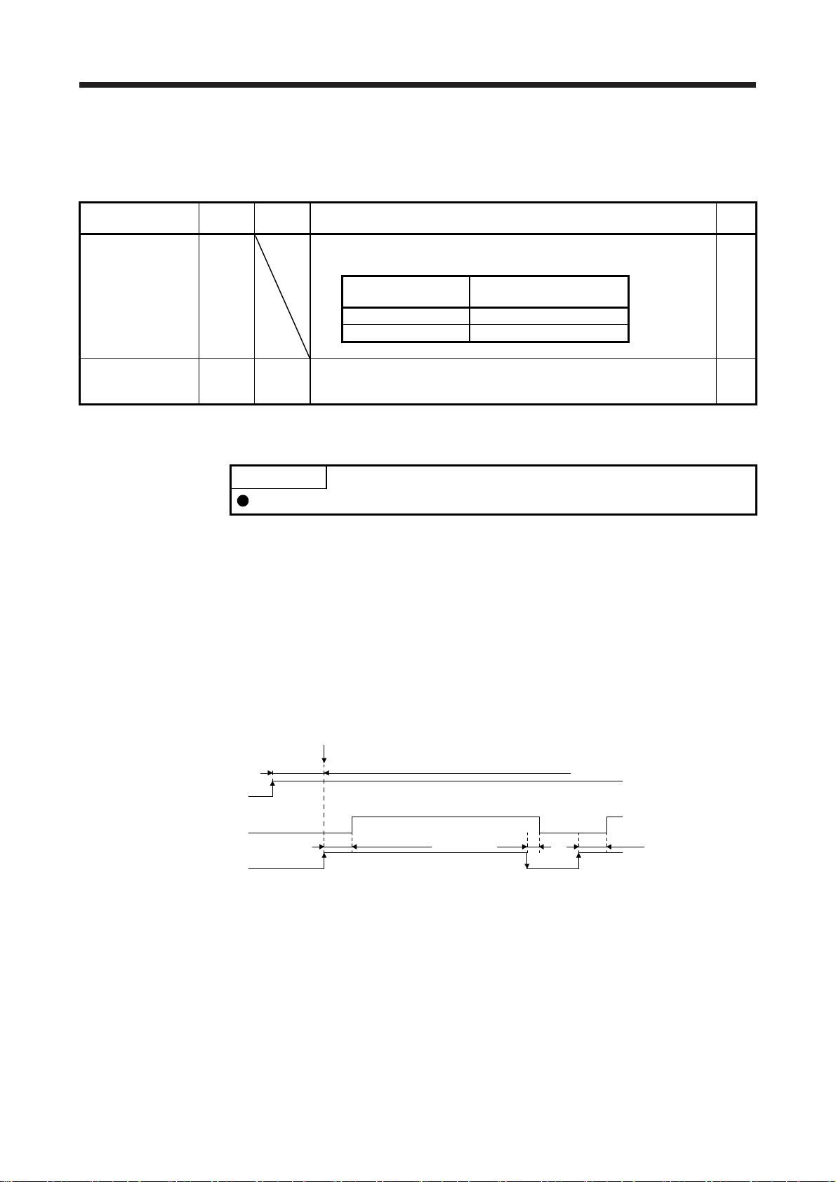
2.3 Signal (device) explanations
For details of the devices and I/O interfaces (symbols in I/O division column in the table) not described in the
table, refer to sections 3.5 and 3.9 in "MR-JE-_C Servo Amplifier Instruction Manual".
Device Symbol
Proximity dog DOG Turning off DOG will detect a proximity dog. The polarity for dog detection can
Connector
pin No.
be changed with [Pr. PT29].
Function and application
_ _ _ 0 Detection with off
_ _ _ 1 Detection with on
Touch probe 1 TPR1 CN3-6 The touch probe function that executes current position latch by sensor input
can be used. For details of the touch probe function, refer to "MR-JE-_C Servo
Amplifier Instruction Manual (Network)".
[Pr. PT29]
Polarity for proximity dog
detection
2.4 Power-on sequence
POINT
The output signal, etc. may be unstable at power-on.
I/O
division
DI-1
DI-1
(1) Power-on procedure
1) Always wire the power supply as shown in above section 3.1 of "MR-JE-_C Servo Amplifier
Instruction Manual" using the magnetic contactor with the power supply (L1/L2/L3). Configure up
an external sequence to switch off the magnetic contactor as soon as an alarm occurs.
2) The servo amplifier receives the servo-on command in 3 s to 4 s + network initial communication
time after the power supply is switched on.
(Refer to (2) in this section.)
(2) Timing chart
Power supply
Base circuit
Servo-on command
(from controller)
ON
OFF
ON
OFF
ON
OFF
Servo-on command accepted
(3 s to 4 s + network initial communication time)
95 ms 10 ms 95 ms
2 - 5
Page 21

2. SIGNALS AND WIRING
MEMO
2 - 6
Page 22

3. STARTUP
3. STARTUP
The items shown in the following table are the same with the contents of "MR-JE-_C Servo Amplifier
Instruction Manual”. For details, refer to each section indicated in the detailed explanation field. "MR-JE-_C"
means "MR-JE-_C Servo Amplifier Instruction Manual".
Switching power on for the first time MR-JE-_C section 4.1
Display and operation section MR-JE-_C section 4.5
Test operation MR-JE-_C section 4.6
Test operation mode MR-JE-_C section 4.7
3.1 Startup
Connect the servo motor with a machine after confirming that the servo motor operates properly alone.
(1) Power on
When the power is switched on, "b01" (when the identification number is 01h) appears on the servo
amplifier display.
When you use the absolute position detection system, first power-on results in [AL. 25 Absolute position
erased] and the servo-on cannot be ready. [AL. 25] can be deactivated by cycling the power.
Also, if the power is switched on when the servo motor is rotated at a speed of 3000 r/min or higher, a
position mismatch may occur due to external force or the like. Power must therefore be switched on
when the servo motor is at a stop.
(2) Parameter setting
Item Detailed explanation
POINT
The following encoder cables are of four-wire type. When using any of these
encoder cables, set [Pr. PC04] to "1 _ _ _" to select the four-wire type. An
incorrect setting will result in [AL. 16 Encoder initial communication error 1].
MR-EKCBL30M-L
MR-EKCBL30M-H
MR-EKCBL40M-H
MR-EKCBL50M-H
Set the parameters according to the structure and specifications of the machine. Refer to chapter 4 for
details.
After setting the above parameters, turn off the power as necessary. Then switch power on again to
enable the parameter values.
(3) Servo-on
Enable the servo-on with the following procedure.
(a) Turn on the power.
(b) Transmit the servo-on command with the controller.
When the servo-on status is enabled, the servo amplifier is ready to operate and the servo motor is
locked.
3 - 1
Page 23

3. STARTUP
(4) Home position return
Always perform home position return before starting positioning operation.
(5) Stop
If any of the following situations occurs, the servo amplifier suspends and stops the operation of the
servo motor.
Turn off the servo-on command after the servo motor has stopped, and then switch the power off.
Refer to section 3.10 in "MR-JE-_C Servo Amplifier Instruction Manual" for the servo motor with an
electromagnetic brake.
Controller
Servo amplifier
Note 1. This is for CC-Link IE Field Network Basic. If an error occurs, RX (n + 3) F is set to "0" (cyclic communication ready turns off).
2. Refer to "MELSERVO-JE Servo Amplifier Instruction Manual (Troubleshooting)" for details of alarms and warnings.
Operation/command Stopping condition
Servo-off command The base circuit is shut off, and the servo motor coasts.
Ready-off command
Quick stop command The servo motor decelerates to a stop.
Error occurrence (Note 1) The servo motor decelerates to a stop.
Alarm occurrence
EM2 (Forced stop 2) off
LSP (Forward rotation
stroke end) off or LSN
(Reverse rotation stroke
end) off
The base circuit is shut off and the dynamic brake operates to bring the servo motor to
a stop.
The servo motor decelerates to a stop. With some alarms; however, the dynamic
brake operates to stop the servo motor. (Note 2)
The servo motor decelerates to a stop. [AL. E6 Servo forced stop warning] occurs. In
the torque control mode, EM2 functions the same as EM1
The servo motor stops immediately and will be servo locked. Operation in the
opposite direction is possible.
3 - 2
Page 24
4. PARAMETERS
4. PARAMETERS
CAUTION
4.1 Parameter list
Never make a drastic adjustment or change to the parameter values as doing so
will make the operation unstable.
Do not change the parameter settings as described below. Doing so may cause
an unexpected condition, such as failing to start up the servo amplifier.
Changing the values of the parameters for manufacturer setting
Setting a value out of the range
Changing the fixed values in the digits of a parameter
When you write parameters with the controller, make sure that the identification
No. of the servo amplifier is set correctly. Otherwise, the parameter settings of
another identification No. may be written, possibly causing the servo amplifier to
be an unexpected condition.
POINT
To enable a parameter whose symbol is preceded by *, cycle the power after
setting it. However, the time will be longer depending on a setting value of [Pr.
PF25 Instantaneous power failure tough drive - Detection time] when
"instantaneous power failure tough drive selection" is enabled in [Pr. PA20].
Refer to chapter 5 in "MR-JE-_C Servo Amplifier Instruction Manual" for the parameters with "MR-JE-_C" in
the detailed explanation field.
4 - 1
Page 25
4. PARAMETERS
4.1.1 Basic setting parameters ([Pr. PA_ _ ])
POINT
The following parameters cannot be used in the profile mode.
[Pr. PA05 Number of command input pulses per revolution]
[Pr. PA13 Command pulse input form]
No. Symbol Name
PA01 *STY Operation mode 1000h Section 4.2.1
PA02 *REG Regenerative option 0000h MR-JE-_C
PA03 *ABS Absolute position detection system 0000h Section 4.2.1
PA04 *AOP1 Function selection A-1 2000h MR-JE-_C
PA05 *FBP Number of command input pulses per revolution 10000
PA06 CMX Electronic gear numerator (command pulse multiplication numerator) 1 Section 4.2.1
PA07 CDV Electronic gear denominator (command pulse multiplication denominator) 1
PA08 ATU Auto tuning mode 0001h MR-JE-_C
PA09 RSP Auto tuning response 16
PA10 INP In-position range 100 [pulse] Section 4.2.1
PA11 TLP Forward rotation torque limit 1000.0 [%]
PA12 TLN Reverse rotation torque limit 1000.0 [%]
PA13 *PLSS Command pulse input form 0100h MR-JE-_C
PA14 *POL Rotation direction selection 0 Section 4.2.1
PA15 *ENR Encoder output pulses 4000 [pulse/rev] MR-JE-_C
PA16 *ENR2 Encoder output pulses 2 1
PA17 For manufacturer setting 0000h
PA18 0000h
PA19 *BLK Parameter writing inhibit 00AAh
PA20 *TDS Tough drive setting 0000h
PA21 *AOP3 Function selection A-3 0001h Section 4.2.1
PA22 For manufacturer setting 0000h MR-JE-_C
PA23 DRAT Drive recorder arbitrary alarm trigger setting 0000h
PA24 AOP4 Function selection A-4 0000h
PA25 OTHOV One-touch tuning - Overshoot permissible level 0 [%]
PA26 *AOP5 Function selection A-5 0000h
PA27 For manufacturer setting 0000h
PA28 *AOP6 Function selection A-6 0000h
PA29 For manufacturer setting 0000h
PA30 0000h
PA31 0000h
PA32 0000h
Initial
value
Unit
Detailed
explanation
4 - 2
Page 26
4. PARAMETERS
4.1.2 Gain/filter setting parameters ([Pr. PB_ _ ])
No. Symbol Name
PB01 FILT Adaptive tuning mode (adaptive filter II) 0000h MR-JE-_C
PB02 VRFT Vibration suppression control tuning mode (advanced vibration
suppression control II)
PB03 PST Position command acceleration/deceleration time constant (position
smoothing)
PB04 FFC Feed forward gain 0 [%]
PB05 For manufacturer setting 500
PB06 GD2 Load to motor inertia ratio 7.00 [Multiplier]
PB07 PG1 Model loop gain 15.0 [rad/s]
PB08 PG2 Position loop gain 37.0 [rad/s]
PB09 VG2 Speed loop gain 823 [rad/s]
PB10 VIC Speed integral compensation 33.7 [ms]
PB11 VDC Speed differential compensation 980
PB12 OVA Overshoot amount compensation 0 [%]
PB13 NH1 Machine resonance suppression filter 1 4500 [Hz]
PB14 NHQ1 Notch shape selection 1 0000h
PB15 NH2 Machine resonance suppression filter 2 4500 [Hz]
PB16 NHQ2 Notch shape selection 2 0000h
PB17 NHF Shaft resonance suppression filter 0000h
PB18 LPF Low-pass filter setting 3141 [rad/s]
PB19 VRF11 Vibration suppression control 1 - Vibration frequency 100.0 [Hz]
PB20 VRF12 Vibration suppression control 1 - Resonance frequency 100.0 [Hz]
PB21 VRF13 Vibration suppression control 1 - Vibration frequency damping 0.00
PB22 VRF14 Vibration suppression control 1 - Resonance frequency damping 0.00
PB23 VFBF Low-pass filter selection 0100h
PB24 *MVS Slight vibration suppression control 0000h
PB25 *BOP1 Function selection B-1 0000h
PB26 *CDP Gain switching function 0000h
PB27 CDL Gain switching condition 10 [kpulse/s]/
PB28 CDT Gain switching time constant 1 [ms]
PB29 GD2B Load to motor inertia ratio after gain switching 7.00 [Multiplier]
PB30 PG2B Position loop gain after gain switching 0.0 [rad/s]
PB31 VG2B Speed loop gain after gain switching 0 [rad/s]
PB32 VICB Speed integral compensation after gain switching 0.0 [ms]
PB33 VRF11B Vibration suppression control 1 - Vibration frequency after gain switching 0.0 [Hz]
PB34 VRF12B Vibration suppression control 1 - Resonance frequency after gain
switching
PB35 VRF13B Vibration suppression control 1 - Vibration frequency damping after gain
switching
PB36 VRF14B Vibration suppression control 1 - Resonance frequency damping after
gain switching
PB37
PB38 0.00
PB39 0.00
PB40 0.00
PB41 0000h
PB42 0000h
PB43 0000h
PB44 0.00
PB45 CNHF Command notch filter 0000h
PB46 NH3 Machine resonance suppression filter 3 4500 [Hz]
PB47 NHQ3 Notch shape selection 3 0000h
For manufacturer setting 1600
Initial
value
0000h
0 [ms]
0.0 [Hz]
0.00
0.00
Unit
[pulse]/
[r/min]
Detailed
explanation
4 - 3
Page 27
4. PARAMETERS
No. Symbol Name
PB48 NH4 Machine resonance suppression filter 4 4500 [Hz] MR-JE-_C
PB49 NHQ4 Notch shape selection 4 0000h
PB50 NH5 Machine resonance suppression filter 5 4500 [Hz]
PB51 NHQ5 Notch shape selection 5 0000h
PB52 VRF21 Vibration suppression control 2 - Vibration frequency 100.0 [Hz]
PB53 VRF22 Vibration suppression control 2 - Resonance frequency 100.0 [Hz]
PB54 VRF23 Vibration suppression control 2 - Vibration frequency damping 0.00
PB55 VRF24 Vibration suppression control 2 - Resonance frequency damping 0.00
PB56 VRF21B Vibration suppression control 2 - Vibration frequency after gain switching 0.0 [Hz]
PB57 VRF22B Vibration suppression control 2 - Resonance frequency after gain
switching
PB58 VRF23B Vibration suppression control 2 - Vibration frequency damping after gain
switching
PB59 VRF24B Vibration suppression control 2 - Resonance frequency damping after
gain switching
PB60 PG1B Model loop gain after gain switching 0.0 [rad/s]
PB61 For manufacturer setting 0.0
PB62 0000h
PB63 0000h
PB64 0000h
Initial
value
0.0 [Hz]
0.00
0.00
Unit
Detailed
explanation
4 - 4
Page 28
4. PARAMETERS
4.1.3 Extension setting parameters ([Pr. PC_ _ ])
POINT
The following parameters cannot be used in the profile mode.
[Pr. PC04 Torque command time constant]
[Pr. PC05 Internal speed command 1/internal speed limit 1]
[Pr. PC06 Internal speed command 2/internal speed limit 2]
[Pr. PC07 Internal speed command 3/internal speed limit 3]
[Pr. PC08 Internal speed command 4/internal speed limit 4]
[Pr. PC09 Internal speed command 5/internal speed limit 5]
[Pr. PC10 Internal speed command 6/internal speed limit 6]
[Pr. PC11 Internal speed command 7/internal speed limit 7]
[Pr. PC12 Analog speed command - Maximum speed/Analog speed limit Maximum speed]
[Pr. PC13 Analog torque command maximum output]
[Pr. PC32 Command input pulse multiplication numerator 2]
[Pr. PC33 Command input pulse multiplication numerator 3]
[Pr. PC34 Command input pulse multiplication numerator 4]
No. Symbol Name
PC01 STA Acceleration time constant 0 [ms] Section 4.2.2
PC02 STB Deceleration time constant 0 [ms]
PC03 STC S-pattern acceleration/deceleration time constant 0 [ms] MR-JE-_C
PC04 TQC Torque command time constant 0 [ms]
PC05 SC1 Internal speed command 1 100.00 [r/min]
Internal speed limit 1
PC06 SC2 Internal speed command 2 500.00 [r/min]
Internal speed limit 2
PC07 SC3 Internal speed command 3 1000.00 [r/min]
Internal speed limit 3
PC08 SC4 Internal speed command 4 200.00 [r/min]
Internal speed limit 4
PC09 SC5 Internal speed command 5 300.00 [r/min]
Internal speed limit 5
PC10 SC6 Internal speed command 6 500.00 [r/min]
Internal speed limit 6
PC11 SC7 Internal speed command 7 800.00 [r/min]
Internal speed limit 7
PC12 VCM Analog speed command - Maximum speed 0.00 [r/min]
Analog speed limit - Maximum speed
PC13 TLC Analog torque command maximum output 100.0 [%]
PC14
PC15 0000h
PC16 MBR Electromagnetic brake sequence output 0 [ms]
PC17 ZSP Zero speed 50 [r/min]
PC18 *BPS Alarm history clear 0000h
PC19 *ENRS Encoder output pulse selection 0000h
PC20
PC21 0000h
PC22 *COP1 Function selection C-1 0020h
PC23 *COP2 Function selection C-2 0000h
PC24 *COP3 Function selection C-3 0000h
For manufacturer setting 0000h
For manufacturer setting 0
Initial
value
Unit
Detailed
explanation
4 - 5
Page 29
4. PARAMETERS
No. Symbol Name
PC25 *COP4 Function selection C-4 0000h Section 4.2.2
PC26 *COP5 Function selection C-5 0000h MR-JE-_C
PC27 *COP6 Function selection C-6 0000h
PC28 For manufacturer setting 0000h
PC29 *COP8 Function selection C-8 0120h Section 4.2.2
PC30 STA2 Acceleration time constant 2 0 [ms] MR-JE-_C
PC31 STB2 Deceleration time constant 2 0 [ms]
PC32 CMX2 Command input pulse multiplication numerator 2 1
PC33 CMX3 Command input pulse multiplication numerator 3 1
PC34 CMX4 Command input pulse multiplication numerator 4 1
PC35 TL2 Internal torque limit 2 1000.0 [%]
PC36 For manufacturer setting 0000h
PC37 VCO Analog speed command offset 0 [mV]
PC38 TPO Analog torque command offset 0 [mV]
Analog torque limit offset
PC39
PC40 0
PC41 0
PC42 0
PC43 ERZ Error excessive alarm detection level 0 [rev]
PC44
PC45 0000h
PC46 0
PC47 0
PC48 0
PC49 0
PC50 0000h
PC51 RSBR Forced stop deceleration time constant 100 [ms]
PC52
PC53 0
PC54 RSUP1 Vertical axis freefall prevention compensation amount 0 [0.0001 rev]
PC55
PC56 100
PC57 0000h
PC58 0
PC59 0000h
PC60 *COPD Function selection C-D 0000h
PC61 For manufacturer setting 0000h
PC62 0000h
PC63 0000h
PC64 0000h
PC65 0000h
PC66 0
PC67 0
PC68 0
PC69 0
PC70 0
PC71 0040h
PC72 0000h
PC73 ERW Error excessive warning level 0 [rev]
PC74 For manufacturer setting 0000h
For manufacturer setting 0
For manufacturer setting 0000h
For manufacturer setting 0
For manufacturer setting 0
Initial
value
Unit
Detailed
explanation
4 - 6
Page 30
4. PARAMETERS
No. Symbol Name
PC75 FEWL Following error output level 0000h 10-3 [degree]/
PC76 FEWH 00C0h
PC77 FEWF Following error output filtering time 10 [ms]
PC78 For manufacturer setting 0000h MR-JE-_C
PC79 0000h
PC80 0000h
Initial
value
Unit
[pulse]
4.1.4 I/O setting parameters ([Pr. PD_ _ ])
POINT
The following parameters cannot be used in the profile mode.
[Pr. PD05 Input device selection 1L]
[Pr. PD06 Input device selection 1M]
[Pr. PD08 Input device selection 2L]
[Pr. PD09 Input device selection 2M]
[Pr. PD11 Input device selection 3L]
[Pr. PD12 Input device selection 3M]
[Pr. PD14 Input device selection 4L]
[Pr. PD15 Input device selection 4M]
[Pr. PD17 Input device selection 5L]
[Pr. PD18 Input device selection 5M]
[Pr. PD23 Input device selection 7L]
[Pr. PD24 Input device selection 7M]
[Pr. PD26 Input device selection 8L]
[Pr. PD27 Input device selection 8M]
Detailed
explanation
Section 4.2.2
No. Symbol Name
PD01 *DIA1 Input signal automatic on selection 1 0000h MR-JE-_C
PD02 For manufacturer setting 0000h
PD04 0000h
PD05 *DI1L Input device selection 1L 0202h
PD06 *DI1M Input device selection 1M 0202h
PD07 *DI1H Input device selection 1H 002Bh Section 4.2.3
PD08 *DI2L Input device selection 2L 0A0Ah MR-JE-_C
PD09 *DI2M Input device selection 2M 0700h
PD10 *DI2H Input device selection 2H 000Ah Section 4.2.3
PD11 *DI3L Input device selection 3L 0B0Bh MR-JE-_C
PD12 *DI3M Input device selection 3M 0800h
PD13 *DI3H Input device selection 3H 000Bh Section 4.2.3
PD14 *DI4L Input device selection 4L 0703h MR-JE-_C
PD15 *DI4M Input device selection 4M 3807h
PD16 *DI4H Input device selection 4H 0000h Section 4.2.3
PD17 *DI5L Input device selection 5L 0806h MR-JE-_C
PD18 *DI5M Input device selection 5M 2008h
PD19 *DI5H Input device selection 5H 0000h Section 4.2.3
Initial
value
Unit
Detailed
explanation
PD03 0000h
4 - 7
Page 31

4. PARAMETERS
No. Symbol Name
PD20
PD21 0000h
PD22 0000h
PD23 *DI7L Input device selection 7L 0000h
PD24 *DI7M Input device selection 7M 0000h
PD25 *DI7H Input device selection 7H 002Ch Section 4.2.3
PD26 *DI8L Input device selection 8L 0000h MR-JE-_C
PD27 *DI8M Input device selection 8M 0000h
PD28 *DI8H Input device selection 8H 0000h
PD29 *DO1 Output device selection 1 0002h
PD30 *DO2 Output device selection 2 0003h
PD31 *DO3 Output device selection 3 0000h
PD32 *DO4 Output device selection 4 0004h
PD33 For manufacturer setting 0000h MR-JE-_C
PD34 *DIF Input filter setting 0004h
PD35 *DOP1 Function selection D-1 0101h Section 4.2.3
PD36 For manufacturer setting 0000h MR-JE-_C
PD37 *DOP3 Function selection D-3 0000h
PD38 *DOP4 Function selection D-4 3000h Section 4.2.3
PD39 *DOP5 Function selection D-5 0000h MR-JE-_C
PD40 For manufacturer setting 0000h
PD41 *TPOP Touch probe function selection 0000h Section 4.2.3
PD42
PD43 0000h
PD44 0000h
PD45 0000h
PD46 0000h
PD47 0000h
PD48 0000h
For manufacturer setting 0000h
For manufacturer setting 0
Initial
value
Unit
4.1.5 Extension setting 2 parameters ([Pr. PE_ _ ])
Detailed
explanation
MR-JE-_C
Section 4.2.3
MR-JE-_C
No. Symbol Name
PE01
PE02 0000h
PE03 0000h
PE04 0
PE05 0
PE06 0
PE07 0
PE08 0
PE09 0000h
PE10 0000h
PE11 0000h
PE12 0000h
PE13 0000h
PE14 0111h
PE15 20
PE16 0000h
PE17 0000h
PE18 0000h
For manufacturer setting 0000h
Initial
value
Unit
Detailed
explanation
MR-JE-_C
4 - 8
Page 32

4. PARAMETERS
No. Symbol Name
PE19
PE20 0000h
PE21 0000h
PE22 0000h
PE23 0000h
PE24 0000h
PE25 0000h
PE26 0000h
PE27 0000h
PE28 0000h
PE29 0000h
PE30 0000h
PE31 0000h
PE32 0000h
PE33 0000h
PE34 0
PE35 0
PE36 0.0
PE37 0.00
PE38 0.00
PE39 0
PE40 0000h
PE41 EOP3 Function selection E-3 0000h
PE42
PE43 0.0
PE44 LMCP Lost motion compensation positive-side compensation value selection 0 [0.01%] Section 4.2.4
PE45 LMCN Lost motion compensation negative-side compensation value selection 0 [0.01%]
PE46 LMFLT Lost motion filter setting 0 [0.1 ms]
PE47 TOF Torque offset 0 [0.01%]
PE48 *LMOP Lost motion compensation function selection 0000h
PE49 LMCD Lost motion compensation timing 0 [0.1 ms]
PE50 LMCT Lost motion compensation non-sensitive band 0 [pulse]/
PE51
PE52 0000h
PE53 0000h
PE54 0000h
PE55 0000h
PE56 0000h
PE57 0000h
PE58 0000h
PE59 0000h
PE60 0000h
PE61 0.00
PE62 0.00
PE63 0.00
PE64 0.00
For manufacturer setting 0000h
For manufacturer setting 0
For manufacturer setting 0000h
Initial
value
Unit
[kpulse]
Detailed
explanation
MR-JE-_C
MR-JE-_C
4 - 9
Page 33

4. PARAMETERS
4.1.6 Extension setting 3 parameters ([Pr. PF_ _ ])
No. Symbol Name
PF01
PF02 0000h
PF03 0000h
PF04 0
PF05 0
PF06 0000h
PF07 1
PF08 1
PF09 *FOP5 Function selection F-5 0003h
PF10
PF11 0000h
PF12 10000
PF13 100
PF14 100
PF15 2000
PF16 0000h
PF17 10
PF18 0000h
PF19 0000h
PF20 0000h
PF21 DRT Drive recorder switching time setting 0 [s]
PF22 For manufacturer setting 200
PF23 OSCL1 Vibration tough drive - Oscillation detection level 50 [%]
PF24 *OSCL2 Vibration tough drive function selection 0000h
PF25 CVAT Instantaneous power failure tough drive - Detection time 200 [ms]
PF26
PF27 0
PF28 0
PF29 0000h
PF30 0
PF31 FRIC Machine diagnosis function - Friction judgment speed 0 [r/min]
PF32
PF33 0000h
PF34 0000h
PF35 0000h
PF36 0000h
PF37 0000h
PF38 0000h
PF39 0000h
PF40 0
PF41 0
PF42 0
PF43 0
PF44 0
PF45 0000h
PF46 0
PF47 0000h
PF48 0000h
For manufacturer setting 0000h
For manufacturer setting 0000h
For manufacturer setting 0
For manufacturer setting 50
Initial
value
Unit
Detailed
explanation
MR-JE-_C
4 - 10
Page 34

4. PARAMETERS
4.1.7 Positioning control parameters ([Pr. PT_ _ ])
No. Symbol Name
PT01 *CTY Command mode selection 0300h Section 4.2.5
PT02 For manufacturer setting 0001h
PT03 *FTY Feeding function selection 0000h Section 4.2.5
PT04 For manufacturer setting 0000h
PT05 ZRF Home position return speed 100.00 [r/min] Section 4.2.5
PT06 CRF Creep speed 10.00 [r/min]
PT07 ZST Home position shift distance 0 10-3 [degree]/
PT08 For manufacturer setting 0
PT09 DCT Travel distance after proximity dog 0 10-3 [degree]/
PT10 ZTM Stopper type home position return stopper time 100 [ms]
PT11 ZTT Stopper type home position return torque limit value 15.0 [%]
PT12 For manufacturer setting 0
PT13 100.00
PT14 0
PT15 LMPL Software limit + 0000h 10-3 [degree]/
PT16 LMPH 0000h 10-3 [degree]/
PT17 LMNL Software limit - 0000h 10-3 [degree]/
PT18 LMNH 0000h 10-3 [degree]/
PT19 For manufacturer setting 0000h
PT20 0000h
PT21 0000h
PT22 0000h
PT23 0
PT24 0
PT25 0
PT26 *TOP2 Function selection T-2 0000h Section 4.2.5
PT27 For manufacturer setting 0000h
PT28 8
PT29 *TOP3 Function selection T-3 0000h Section 4.2.5
PT30 For manufacturer setting 0000h
PT31 0000h
PT32 0000h
PT33 0000h
PT34 0000h
PT35 0000h
PT36 0000h
PT37 10
PT38 0000h
PT39 100
PT40 0
PT41 ORP Home position return inhibit function selection 0000h Section 4.2.5
PT42 For manufacturer setting 0
PT43 0
PT44 0000h
Initial
value
Unit
[pulse]
[pulse]
[pulse]
[pulse]
[pulse]
[pulse]
Detailed
explanation
Section 4.2.5
Section 4.2.5
4 - 11
Page 35

4. PARAMETERS
No. Symbol Name
PT45 HMM Home position return method 37 Section 4.2.5
PT46 For manufacturer setting 0000h
PT47 0000h
PT48 0000h
PT49 TQS Torque slope 0.0 [%/s] Section 4.2.5
PT50 PVC Profile speed command 100.00 [r/min]
PT51 MPVC Maximum profile speed 20000.00 [r/min]
PT52 VLMT Speed limit 500.00 [r/min]
PT53 For manufacturer setting 0000h
PT54 0000h
PT55 0000h
PT56 0000h
PT57 ZSTH Home position shift distance (extension parameter) 0 10-3 [degree]/
PT58 For manufacturer setting 0
PT59 DCTH Travel distance after proximity dog (extension parameter) 0 10-3 [degree]/
PT60 *TOP8 Function selection T-8 0000h
PT61 HMA Home position return acceleration time constant 0 [ms]
PT62 HMB Home position return deceleration time constant 0 [ms]
PT63 ZSP2L Zero speed 2 level 50.00 [r/min]
PT64 ZSP2F Zero speed 2 filtering time 10 [ms]
PT65 INP2R In-position 2 output range 100 10-3 [degree]/
PT66 INP2F In-position 2 output filtering time 10 [ms]
PT67 SA2R Speed reached 2 output range 20.00 [r/min]
PT68 SA2F Speed reached 2 output filtering time 10 [ms]
PT69 For manufacturer setting 0000h
PT70 0000h
PT71 0000h
PT72 0000h
PT73 0000h
PT74 0000h
PT75 0000h
PT76 0000h
PT77 0000h
PT78 0000
PT79 0000
PT80 0000
Initial
value
Unit
[pulse]
[pulse]
[pulse]
Detailed
explanation
Section 4.2.5
Section 4.2.5
4 - 12
Page 36

4. PARAMETERS
4.2 Detailed list of parameters
POINT
For parameters which are not described in this section, refer to chapter 5 of
"MR-JE-_C Servo Amplifier Instruction Manual".
Set a value to each "x" in the "Setting digit" columns.
4.2.1 Basic setting parameters ([Pr. PA_ _ ])
No./symbol/
name
PA01
*STY
Operation
mode
_ _ x _ For manufacturer setting 0h
_ x _ _ 0h
x _ _ _ 1h
PA03
*ABS
Absolute
position
detection
system
_ _ x _ For manufacturer setting 0h
_ x _ _ 0h
x _ _ _ 0h
Setting
digit
_ _ _ x Control mode selection
To use the profile mode, select "9" (Profile mode (pp/pv/tq)).
0: Position control mode (P)
1: Position control mode and speed control mode (P/S)
2: Speed control mode (S)
3: Speed control mode and torque control mode (S/T)
4: Torque control mode (T)
5: Torque control mode and position control mode (T/P)
6: Positioning mode (point table method) (CP)
8: Positioning mode (indexer method) (PS)
9: Profile mode (pp/pv/tq)
_ _ _ x Absolute position detection system selection
Set this digit when using the absolute position detection system.
0: Disabled (used in the incremental system)
2: Enabled (absolute position detection system)
Setting "1" will trigger [AL. 37].
Function
Initial
value
[unit]
0h
0h
4 - 13
Page 37

4. PARAMETERS
No./symbol/
name
PA06
CMX
Electronic
gear
numerator
(command
pulse
multiplication
numerator)
Setting
digit
Set an electronic gear numerator.
To enable the parameter, select "Electronic gear (0 _ _ _)" of "Electronic gear selection" in [Pr.
PA21].
In the profile mode, cycle the power to enable the parameter.
The following shows a standard of the setting range of the electronic gear.
1
27649
If the set value is outside this range, noise may be generated during acceleration/deceleration or
operation may not be performed at the preset speed and/or acceleration/deceleration time
constants.
<
CMX
CDV
< 8484
Function
Number of command input pulses per revolution
([Pr. PA05] "1000" to "1000000")
Initial
value
[unit]
1
PA07
CDV
Electronic
gear
denominator
(command
pulse
multiplication
denominator)
PA10
INP
In-position
range
Command
pulse train
Electronic gear selection
(x _ _ _ ) ([Pr. PA21])
"0" (initial value)
"1"
Pt (servo motor resolution): 131072 pulses/rev
Electronic gear
([Pr. PA06]/[Pr. PA07])
CMX
CDV
Pt
FBP
+
Deviation
counter
-
Be sure to set the electronic gear with servo-off state to prevent unexpected operation due to
improper setting.
This parameter corresponds to "Motor revolutions (Index: 6091h, Sub: 1)". When this parameter is
mapped to the link device of CC-Link IE Field Network Basic, the value written with MR
Configurator2 is overwritten by the controller. Thus, do not write a value with MR Configurator2.
Setting range: 1 to 16777215
Set an electronic gear denominator.
To enable the parameter, select "Electronic gear (0 _ _ _)" of "Electronic gear selection" in [Pr.
PA21].
In the profile mode, cycle the power to enable the parameter.
Setting range: 1 to 16777215
Set an in-position range per command pulse.
To change it to the servo motor encoder pulse unit, set [Pr. PC24].
-3
When [Pr. PC24] is set to "_ _ _ 0" in the profile mode, the unit can be changed 10
[degree] or
[pulse] with the setting of [Pr. PT01].
Setting range: 0 to 65535
Servo motor
M
Encoder
1
100
Refer to
Function
column
for unit.
4 - 14
Page 38

4. PARAMETERS
No./symbol/
name
PA11
TLP
Forward
rotation
torque limit
PA12
TLN
Reverse
rotation
torque limit
Setting
digit
You can limit the torque generated by the servo motor.
Set the parameter on the assumption that the rated torque is 100.0 [%]. Set the parameter to limit
the torque of the servo motor in the CW power running or CCW regeneration.
The polarity of the torque limit changes depending on the [Pr. PA14] setting. Set this parameter to
"0.0" to generate no torque.
If a value larger than the maximum torque of the servo motor is set, the value will be limited to the
maximum torque of the servo motor.
This parameter corresponds to "Positive torque limit value (Index: 60E0h)". When this parameter is
mapped to the link device of CC-Link IE Field Network Basic, the value written with MR
Configurator2 is overwritten by the controller. Thus, do not write a value with MR Configurator2.
Setting range: 0.0 to 1000.0
You can limit the torque generated by the servo motor.
Set the parameter on the assumption that the rated torque is 100.0 [%]. Set this parameter when
limiting the torque of the servo motor in the CW power running or CCW regeneration.
The polarity of the torque limit changes depending on the [Pr. PA14] setting. Set this parameter to
"0.0" to generate no torque.
If a value larger than the maximum torque of the servo motor is set, the value will be limited to the
maximum torque of the servo motor.
This parameter corresponds to "Negative torque limit value (Index: 60E1h)". When this parameter
is mapped to the link device of CC-Link IE Field Network Basic, the value written with MR
Configurator2 is overwritten by the controller. Thus, do not write a value with MR Configurator2.
Setting range: 0.0 to 1000.0
Function
Initial
value
[unit]
1000.0
[%]
1000.0
[%]
4 - 15
Page 39

4. PARAMETERS
No./symbol/
name
PA14
*POL
Rotation
direction
selection
0 CCW CW
1 CW CCW
Setting value Servo motor rotation direction
Setting
digit
Select a rotation direction or travel direction.
The torque polarity changes depending on the combination of this parameter and [Pr. PC29 POL
reflection selection at torque mode].
In the profile position mode/profile velocity mode
Setting
value
In the profile torque mode
[Pr. PA14] [Pr. PC29]
The following shows the servo motor rotation directions.
Positioning address
Speed command: Positive
0
1
Servo motor rotation direction
Position mode
increase/
Velocity mode
0 _ _ _:
Enabled
1 _ _ _:
Disabled
0 _ _ _:
Enabled
1 _ _ _:
Disabled
Function
Position mode
Positioning address
decrease/
Velocity mode
Speed command: Negative
Torque mode
Torque command: Forward
CCW CW
CCW CW
CW CCW
CCW CW
Torque mode
Torque command: Reverse
Initial
value
[unit]
0
Forward rotation (CCW)
Reverse rotation (CW)
Setting range: 0, 1
PA21
*AOP3
Function
selection A-3
_ _ x _ For manufacturer setting 0h
_ x _ _ 0h
x _ _ _ Electronic gear selection
_ _ _ x One-touch tuning function selection
0: Disabled
1: Enabled
When the digit is "0", the one-touch tuning is not available.
0: Electronic gear ([Pr. PA06] and [Pr. PA07])
1: Number of command input pulses per revolution ([Pr. PA05])
"1" is not used in the profile mode. Setting "1" triggers [AL. 37 Parameter error].
1h
0h
4 - 16
Page 40

4. PARAMETERS
4.2.2 Extension setting parameters ([Pr. PC_ _ ])
No./symbol/
name
PC01
STA
Acceleration
time constant
PC02
STB
Deceleration
time constant
PC25
*COP4
Function
selection C-4
Setting
digit
Set the acceleration time taken from 0 r/min to the rated speed for the command.
Set the acceleration time constant in the profile position mode and the profile velocity mode.
Setting a value exceeding 20000 ms in the profile position mode will trigger [AL. F4].
Servo motor speed
Rated
speed
Function
If the preset speed command is lower
than the rated speed, acceleration/
deceleration time will be shorter.
Initial
value
[unit]
0
[ms]
0 r/min
[Pr. PC01] setting
For example, for the servo motor with the rated speed of 3000 r/min, set 3000 (3 s) to increase
speed from 0 r/min to 1000 r/min in 1 s.
This parameter corresponds to "Profile acceleration (Index: 6083h)". When this parameter is
mapped to the link device of CC-Link IE Field Network Basic, the value written with MR
Configurator2 is overwritten by the controller. Thus, do not write a value with MR Configurator2.
Setting range: 0 to 50000
Set the deceleration time taken from the rated speed to 0 r/min for the command.
Set the deceleration time constant in the profile position mode and the profile velocity mode.
Setting a value exceeding 20000 ms in the profile position mode will trigger [AL. F4].
This parameter corresponds to "Profile deceleration (Index: 6084h)". When this parameter is
mapped to the link device of CC-Link IE Field Network Basic, the value written with MR
Configurator2 is overwritten by the controller. Thus, do not write a value with MR Configurator2.
Setting range: 0 to 50000
_ _ _ x For manufacturer setting 0h
_ _ x _ 0h
_ x _ _ 0h
x _ _ _ [AL. E9 Main circuit off warning] selection
Select an occurring condition of [AL. E9 Main circuit off warning].
0: Detection with ready-on and servo-on command
1: Detection with servo-on command
This function will be enabled in the profile mode.
[Pr. PC02] setting
Time
0
[ms]
0h
4 - 17
Page 41

4. PARAMETERS
Initial
value
[unit]
1h
0000h
Refer to
Function
column
for unit.
0000h
Refer to
Function
column
for unit.
No./symbol/
name
PC29
*COP8
Function
selection C-8
Setting
digit
_ _ _ x For manufacturer setting 0h
_ _ x _ 2h
_ x _ _ POL reflection selection at torque mode
The polarity of "Target torque (Index: 6071h)", "Torque demand (Index: 6074h)", "Positive torque
limit value (Index: 60E0h)", "Negative torque limit value (Index: 60E1h)", and "Torque actual value
(Index: 6077h)" changes depending on the combination of this parameter and [Pr. PA14 Rotation
direction selection].
0: Enabled
1: Disabled
Function
Setting value Servo motor rotation direction/travel direction
x _ _ _ For manufacturer setting 0h
PC75
FEWL
Following
error output
level
(Lower four
digits)
PC76
FEWH
Following
error output
level
(Upper four
digits)
[Pr. PA14] [Pr. PC29]
digits
0 _ _ _:
Enabled
1 _ _ _:
Disabled
0 _ _ _:
Enabled
1 _ _ _:
Disabled
Lower four
digits
-3
[degree] or [pulse] with the setting of [Pr. PT01].
-3
[degree] or [pulse] with the setting of [Pr. PT01].
0
1
Set a following error output level.
Upper and lower are a set.
This function will be enabled in the profile position mode.
When the state in which the value of droop pulses exceeds the setting value for [Pr. PC75, Pr.
PC76] continues for the time set in [Pr. PC77] or longer, "Statusword (Index: 6041h) bit 13
Following error" will be turned on. However, setting "FFFFFFFFh" will disable it.
Set a value in hexadecimal.
Setting value:
Upper four
The unit can be changed to 10
This parameter corresponds to "Following error window (Index: 6065h)". When this parameter is
mapped to the link device of CC-Link IE Field Network Basic, the value written with MR
Configurator2 is overwritten by the controller. Thus, do not write a value with MR Configurator2.
Setting range: 00000000h to FFFFFFFFh
Set a following error output level.
Upper and lower are a set.
This function will be enabled in the profile position mode.
Refer to [Pr. PC75] for details.
The unit can be changed to 10
Torque mode
Torque command: Forward
CCW or positive direction CW or negative direction
CCW or positive direction CW or negative direction
CW or negative direction CCW or positive direction
CCW or positive direction CW or negative direction
[Pr. PC75]
[Pr. PC76]
Torque mode
Torque command: Reverse
4 - 18
Page 42

4. PARAMETERS
No./symbol/
name
PC77
FEWF
Following
error output
filtering time
4.2.3 I/O setting parameters ([Pr. PD_ _ ])
Setting
digit
Set the time until the following error output turns on.
When the state in which the value of droop pulses exceeds the setting value for [Pr. PC75, Pr.
PC76] continues for the time set in the parameter setting value or longer, "Statusword (Index:
6041h) bit 13 Following error" will be turned on.
This function will be enabled in the profile position mode.
The following error output will be disabled when both [Pr. PC75] and [Pr. PC76] are "FFFFh".
This parameter corresponds to "Following error time out (Index: 6066h)". When this parameter is
mapped to the link device of CC-Link IE Field Network Basic, the value written with MR
Configurator2 is overwritten by the controller. Thus, do not write a value with MR Configurator2.
Setting range: 0 to 65535
Function
Initial
value
[unit]
0000h
Refer to
Function
column
for unit.
No./symbol/
name
PD07
*DI1H
Input device
selection 1H
Setting
digit
Any input device can be assigned to the CN3-2 pin.
_ _ x x Communication command mode - Device selection
Refer to table 4.1 for settings.
_ x _ _ For manufacturer setting 0h
x _ _ _ 0h
Function
Initial
value
[unit]
Table 4.1 Selectable input devices
04 PC (Proportional control)
0A LSP (Forward rotation stroke end)
0B LSN (Reverse rotation stroke end)
0D CDP (Gain switching)
2B DOG (Proximity dog)
2C TPR1 (touch probe 1) (Note)
Note. This can be used when TRP1 is assigned to CN3-6 with [Pr. PD25 Input device selection 7H].
PD10
*DI2H
Input device
selection 2H
x _ _ _ 0h
PD13
*DI3H
Input device
selection 3H
x _ _ _ 0h
PD16
*DI4H
Input device
selection 4H
PD19
*DI5H
Input device
selection 5H
x _ _ _ 0h
Any input device can be assigned to the CN3-3 pin.
_ _ x x Communication command mode - Device selection
_ x _ _ For manufacturer setting 0h
Any input device can be assigned to the CN3-4 pin.
_ _ x x Communication command mode - Device selection
_ x _ _ For manufacturer setting 0h
Any input device can be assigned to the CN3-8 pin.
_ _ x x Communication command mode - Device selection
_ x _ _ For manufacturer setting 0h
x _ _ _ 0h
Any input device can be assigned to the CN3-21 pin.
_ _ x x Communication command mode - Device selection
_ x _ _ For manufacturer setting 0h
Setting
value
Refer to table 4.1 in [Pr. PD07] for settings.
Refer to table 4.1 in [Pr. PD07] for settings.
Refer to table 4.1 in [Pr. PD07] for settings.
Refer to table 4.1 in [Pr. PD07] for settings.
Input device
2Bh
0Ah
0Bh
00h
00h
4 - 19
Page 43

4. PARAMETERS
No./symbol/
name
PD25
*DI7H
Input device
selection 7H
x _ _ _ 0h
PD28
*DI8H
Input device
selection 8H
x _ _ _ 0h
PD29
*DO1
Output device
selection 1
_ x _ _ For manufacturer setting 0h
x _ _ _ 0h
Setting
digit
Any input device can be assigned to the CN3-6 pin.
_ _ x x Communication command mode - Device selection
Refer to table 4.1 in [Pr. PD07] for settings.
_ x _ _ For manufacturer setting 0h
Any input device can be assigned to the CN3-19 pin.
_ _ x x Communication command mode - Device selection
Refer to table 4.1 in [Pr. PD07] for settings.
_ x _ _ For manufacturer setting 0h
_ _ x x Device selection
Any output device can be assigned to the CN3-14 pin.
When "CN3-14 (1 _ _ _)" is selected in "OP output selection" of [Pr. PD38], this digit is disabled
and OP (Encoder Z-phase pulse (open collector)) is assigned to the CN3-14 pin.
Refer to table 4.2 for settings.
Function
Table 4.2 Selectable output devices
_ _ 0 0 Always off
_ _ 0 2 RD (Ready)
_ _ 0 3 ALM (Malfunction)
_ _ 0 4 INP (In-position)
_ _ 0 5 MBR (Electromagnetic brake interlock)
_ _ 0 7 TLC (Limiting torque)
_ _ 0 8 WNG (Warning)
_ _ 0 9 BWNG (Battery warning)
_ _ 0 A SA (Speed reached)
_ _ 0 B VLC (Limiting speed)
_ _ 0 C ZSP (Zero speed detection)
_ _ 0 D MTTR (During tough drive)
_ _ 0 F CDPS (Variable gain selection)
_ _ 1 1 ABSV (Absolute position undetermined)
PD30
*DO2
Output device
selection 2
PD31
*DO3
Output device
selection 3
_ _ x x Device selection
_ x _ _ For manufacturer setting 0h
x _ _ _ 0h
_ _ x x Device selection
_ x _ _ For manufacturer setting 0h
x _ _ _ 0h
Setting
value
Any output device can be assigned to the CN3-15 pin.
When "CN3-15 (2 _ _ _)" is selected in "OP signal output selection" of [Pr. PD38], this digit is
disabled and OP (Encoder Z-phase pulse (open collector)) is assigned to the CN3-15 pin.
Refer to table 4.2 in [Pr. PD29] for settings.
Any output device can be assigned to the CN3-16 pin.
This parameter cannot be used to assign output devices since the OP signal is assigned to the
CN3-16 pin with "OP signal assignment selection" of [Pr. PD38] in the initial setting. To assign
output devices, select a value other than "CN3-16 (3 _ _ _)" (initial value) in "OP signal assignment
selection" of [Pr. PD38].
Refer to table 4.2 in [Pr. PD29] for settings.
Output device
Initial
value
[unit]
2Ch
00h
02h
03h
00h
4 - 20
Page 44

4. PARAMETERS
No./symbol/
name
PD32
*DO4
Output device
selection 4
PD35
*DOP1
Function
selection D-1
_ x _ _ For manufacturer setting 1h
x _ _ _ 0h
PD38
*DOP4
Function
selection D-4
PD41
*TPOP
Touch probe
function
selection
_ x _ _ For manufacturer setting 0h
x _ _ _ 0h
Setting
digit
_ _ x x Device selection
Any output device can be assigned to the CN3-22 pin.
When "CN3-22 (4 _ _ _)" is selected in "OP signal output selection" of [Pr. PD38], this digit is
disabled and OP (Encoder Z-phase pulse (open collector)) is assigned to the CN3-22 pin.
Refer to table 4.2 in [Pr. PD29] for settings.
_ x _ _ For manufacturer setting 0h
x _ _ _ 0h
_ _ _ x It is not used in the profile mode. 1h
_ _ x _ Base circuit status selection for RES (Reset) on
0: Base circuit shut-off
1: No base circuit shut-off
_ _ _ x For manufacturer setting 0h
_ _ x _ 0h
_ x _ _ 0h
x _ _ _ OP signal assignment selection
Select a pin to which the OP (Encoder Z-phase pulse (open collector)) is assigned.
For example, if the OP is assigned to the CN3-14 pin, the OP is outputted regardless of the setting
in [Pr. PD29].
0: Not assigned
1: CN3-14 ([Pr. PD29] disabled)
2: CN3-15 ([Pr. PD30] disabled)
3: CN3-16 ([Pr. PD31] disabled)
4: CN3-22 ([Pr. PD32] disabled)
_ _ _ x For manufacturer setting 0h
_ _ x _ Touch probe signal filter selection
0: Not assigned
1: 0.111 ms
2: 0.222 ms
3: 0.444 ms
Function
4.2.4 Extension setting 2 parameters ([Pr. PE_ _ ])
Initial
value
[unit]
04h
0h
3h
0h
No./symbol/
name
PE44
LMCP
Lost motion
compensation
positive-side
compensation
value
selection
PE45
LMCN
Lost motion
compensation
negative-side
compensation
value
selection
Setting
digit
Set the lost motion compensation for when reverse rotation (CW) switches to forward rotation
(CCW) in increments of 0.01% assuming the rated torque as 100%.
This function will be enabled in the profile position mode.
Setting range: 0 to 30000
Set the lost motion compensation for when forward rotation (CCW) switches to reverse rotation
(CW) in increments of 0.01% assuming the rated torque as 100%.
This function will be enabled in the profile position mode.
Setting range: 0 to 30000
Function
4 - 21
Initial
value
[unit]
0
[0.01%]
0
[0.01%]
Page 45

4. PARAMETERS
No./symbol/
name
PE46
LMFLT
Lost motion
filter setting
PE47
TOF
Torque offset
PE48
*LMOP
Lost motion
compensation
function
selection
_ x _ _ For manufacturer setting 0h
x _ _ _ 0h
PE49
LMCD
Lost motion
compensation
timing
PE50
LMCT
Lost motion
compensation
non-sensitive
band
Setting
digit
Set the time constant of the lost motion compensation filter in increments of 0.1 ms.
When "0" is set, the torque is compensated with the value set in [Pr. PE44] and [Pr. PE45]. When
other than "0" is set, the torque is compensated with the high-pass filter output value of the set time
constant, and the lost motion compensation will continue.
This function will be enabled in the profile position mode.
Setting range: 0 to 30000
Set this when canceling unbalanced torque of vertical axis. Set this assuming the rated torque of
the servo motor as 100%. The torque offset does not need to be set for a machine not generating
unbalanced torque.
The torque offset set with this parameter will be enabled in the position control mode, speed control
mode, and torque control mode. Input commands considering the torque offset in the torque control
mode.
Setting range: -10000 to 10000
_ _ _ x Lost motion compensation selection
0: Disabled
1: Enabled
This function will be enabled in the profile position mode.
_ _ x _ Unit setting of lost motion compensation non-sensitive band
0: 1 pulse unit
1: 1 kpulse unit
This function will be enabled in the profile position mode.
Set the lost motion compensation timing in increments of 0.1 ms.
You can delay the timing to perform the lost motion compensation for the set time.
This function will be enabled in the profile position mode.
Setting range: 0 to 30000
Set the lost motion compensation non-sensitive band. When the fluctuation of droop pulses is
equal to or less than the setting value, the speed will be 0. The setting unit can be changed in [Pr.
PE48]. Set the parameter per encoder unit.
This function will be enabled in the profile position mode.
Setting range: 0 to 65535
Function
Initial
value
[unit]
[0.1 ms]
[0.01 %]
[0.1 ms]
[pulse]/
[kpulse]
0
0
0h
0h
0
0
4 - 22
Page 46

4. PARAMETERS
4.2.5 Positioning control parameters ([Pr. PT_ _ ])
No./symbol/
name
PT01
*CTY
Command
mode
selection
x _ _ _ For manufacturer setting 0h
PT03
*FTY
Feeding
function
selection
x _ _ _ For manufacturer setting 0h
PT05
ZRF
Home
position
return speed
PT06
CRF
Creep speed
PT07
ZST
Home
position shift
distance
PT09
DCT
Travel
distance after
proximity dog
Setting
digit
_ _ _ x For manufacturer setting 0h
_ _ x _ 0h
_ x _ _ Position data unit
0: mm
1: inch
2: degree
3: pulse
"0" and "1" are not used in the profile mode. Setting "0" or "1” triggers [AL. 37 Parameter error].
_ _ _ x For manufacturer setting 0h
_ _ x _ 0h
_ x _ _ Shortest rotation selection per degree
0: Rotation direction specifying
1: Shortest rotation
2: Rotation in address decreasing direction
3: Rotation in address increasing direction
This parameter corresponds to "Positioning option code (Index: 60F2h)". When this parameter is
mapped to the link device of CC-Link IE Field Network Basic, the value written with MR
Configurator2 is overwritten by the controller. Thus, do not write a value with MR Configurator2.
Set the servo motor speed for the home position return.
Setting range: 0 to instantaneous permissible speed
This parameter corresponds to "Speed during search for switch (Index: 6099h, Sub: 1)". When this
parameter is mapped to the link device of CC-Link IE Field Network Basic, the value written with
MR Configurator2 is overwritten by the controller. Thus, do not write a value with MR
Configurator2.
Set a creep speed after proximity dog at home position return.
Setting range: 0 to instantaneous permissible speed
This parameter corresponds to "Speed during search for zero (Index: 6099h, Sub: 2)". When this
parameter is mapped to the link device of CC-Link IE Field Network Basic, the value written with
MR Configurator2 is overwritten by the controller. Thus, do not write a value with MR
Configurator2.
Set the shift distance from Z-phase pulse detection position in the encoder or from the position that
has been set in [Pr. PT09].
31
Up to 2
The unit will be changed to 10
Refer to the Function column of [Pr. PA10] for the command unit of [pulse].
Setting range: 0 to 65535
Set a travel distance after proximity dog at home position return for the count type (front end
detection, Z-phase reference) (Homing method -2, -34) and dog reference.
Up to 2
The following shows the home position return of the dog reference.
Homing without index pulse (Homing method 19, 20, 21, 22, 23, 24, 27, 28)
The unit will be changed to 10
Setting range: 0 to 65535
can be set with [Pr. PT57].
31
can be set with [Pr. PT59].
Dog type (rear end detection, rear end reference) (Homing method -6, -38)
Count type (front end detection, front end reference) (Homing method -7, -39)
Dog type front end reference (Homing method -10, -42)
-3
[degree] or [pulse] with the setting of [Pr. PT01].
-3
[degree] or [pulse] with the setting of [Pr. PT01].
Function
Initial
value
[unit]
100.00
[r/min]
10.00
[r/min]
Refer to
Function
column
for unit.
Refer to
Function
column
for unit.
3h
0h
0
0
4 - 23
Page 47

4. PARAMETERS
No./symbol/
name
PT10
ZTM
Stopper type
home position
return stopper
time
PT11
ZTT
Stopper type
home position
return torque
limit value
PT15
LMPL
Software limit
+
(lower four
digits)
PT16
LMPH
Software limit
+
(upper four
digits)
Setting
digit
Set a time from a moving part touches the stopper and torques reaches to the torque limit of [Pr.
PT11 Stopper type home position return - Torque limit value] to a home position is set for the
stopper type home position return.
Setting range: 5 to 1000
Set a torque limit value with [%] to the maximum torque at stopper type home position return.
Setting "0.0" will be the same as setting "1.0".
Setting range: 0 to 1000
Set an address increasing side of the software stroke limit.
Upper and lower are a set.
Set an address in hexadecimal.
Setting address:
Setting an identical value for "Software limit -" and this parameter will disable the software limit.
(Refer to section 4.3.)
When changing the setting with the parameter, change it during servo-off, in the homing mode,
velocity mode, or torque mode.
In the position mode during servo-on, changing the setting in a certain order may trigger [AL. 35],
[AL. 69], or [AL. 98].
This function will be enabled in the profile mode and cyclic synchronous mode.
The unit can be changed to 10
This parameter corresponds to "Max position limit (Index: 607Dh, Sub: 2)". When this parameter is
mapped to the link device of CC-Link IE Field Network Basic, the value written with MR
Configurator2 is overwritten by the controller. Thus, do not write a value with MR Configurator2.
Setting range: 00000000h to FFFFFFFFh
Upper four
digits
Function
Lower four
digits
[Pr. PT15]
[Pr. PT16]
-3
[degree] or [pulse] with the setting of [Pr. PT01].
Initial
value
[unit]
100
[ms]
15.0
[%]
0000h
Refer to
Function
column
for unit.
0000h
Refer to
Function
column
for unit.
4 - 24
Page 48

4. PARAMETERS
No./symbol/
name
PT17
LMNL
Software limit
(lower four
digits)
PT18
LMNH
Software limit
(upper four
digits)
PT26
*TOP2
Function
selection T-2
_ _ x _ For manufacturer setting 0h
_ x _ _ 0h
x _ _ _ 0h
PT29
*TOP3
Function
selection T-3
Setting
digit
Set an address decreasing side of the software stroke limit.
Upper and lower are a set.
Set an address in hexadecimal.
Setting address:
Upper four
digits
Setting a same value with "Software limit +" will disable the software stroke limit. (Refer to section
4.3.)
When changing the setting with the parameter, change it during servo-off, in the homing mode,
velocity mode, or torque mode.
In the position mode during servo-on, changing the setting in a certain order may trigger [AL. 35],
[AL. 69], or [AL. 98].
This function will be enabled in the profile mode and cyclic synchronous mode.
The unit can be changed to 10
This parameter corresponds to "Min position limit (Index: 607Dh, Sub: 1)". When this parameter is
mapped to the link device of CC-Link IE Field Network Basic, the value written with MR
Configurator2 is overwritten by the controller. Thus, do not write a value with MR Configurator2.
Setting range: 00000000h to FFFFFFFFh
_ _ _ x Electronic gear fraction clear selection
0: Disabled
1: Enabled
Selecting "Enabled" will clear a fraction of the previous command by the electronic gear at start of
the profile mode.
Set the DOG polarity.
_ _ _ x
(HEX)
_ _ x _ For manufacturer setting 0h
_ x _ _ 0h
x _ _ _ 0h
Convert the setting value into hexadecimal as follows.
_ _ _ x (BIN): DOG (Proximity dog) polarity selection
0: Dog detection with off
1: Dog detection with on
_ _ x _ (BIN): For manufacturer setting
_ x _ _ (BIN): For manufacturer setting
x _ _ _ (BIN): For manufacturer setting
Lower four
digits
-3
[degree] or [pulse] with the setting of [Pr. PT01].
Function
[Pr. PT17]
[Pr. PT18]
Initial
value
[unit]
0000h
Refer to
Function
column
for unit.
0000h
Refer to
Function
column
for unit.
0h
0h
000
Setting
DOG (Proximity dog) polarity selection
4 - 25
Initial value
BIN HEX
0
0
0
0
0
Page 49

4. PARAMETERS
No./symbol/
name
PT41
ORP
Home
position
return inhibit
function
selection
PT45
HMM
Home
position
return method
Setting
-2 Count type -34 Count type
-3 Data set type -36 Stopper type
-4 Stopper type
-38 Dog type
-6 Dog type
-39 Count type
-40 Dog cradle type
-9 Dog type last Z-phase
-42 Dog type front end
-10 Dog type front end
-43 Dogless Z-phase
-11 Dogless Z-phase
Setting
digit
_ _ _ x Home position return inhibit selection
0: Disabled (home position return allowed)
1: Enabled (home position return inhibited)
_ _ x _ For manufacturer setting 0h
_ x _ _ 0h
x _ _ _ 0h
Set a home position return method.
Refer to the following table for details.
"Statusword bit13 Homing error" is turned on when the setting is different from the setting value.
This parameter corresponds to "Homing method (Index: 6098h)". When this parameter is mapped
to the link device of CC-Link IE Field Network Basic, the value written with MR Configurator2 is
overwritten by the controller. Thus, do not write a value with MR Configurator2.
Home position
value
-1
-7 Count type
-8 Dog cradle type -41 Dog type last Z-phase
return direction
Address increasing
direction
Home position return
method
Dog type -33
(rear end detection,
Z-phase reference)
(front end detection,
Z-phase reference)
(Stopper position
reference)
(rear end detection,
rear end reference)
(front end detection,
front end reference)
reference
reference
reference
Function
Setting
value
(Stopper position
(rear end detection,
(front end detection,
Home position
return direction
Address decreasing
direction
Home position return
method
Dog type
(rear end detection,
Z-phase reference)
(front end detection,
Z-phase reference)
reference)
rear end reference)
front end reference)
reference
reference
reference
Initial
value
[unit]
0h
37
4 - 26
Page 50

4. PARAMETERS
No./symbol/
name
PT45
HMM
Home
position
return method
5 Address decreasing
6 Address decreasing
7 Address increasing
8 Address increasing
11 Address decreasing
12 Address decreasing
19 Address increasing
20 Address increasing
PT49
TQS
Torque slope
PT50
PVC
Profile speed
command
PT51
MPVC
Maximum
profile speed
PT52
VLMT
Speed limit
Setting
digit
Setting
value
3 Address increasing
4 Address increasing
Set the rate of change of the torque command per second.
Set the speed of the profile speed command.
Set the maximum profile speed.
Set the maximum speed in the torque control.
Home position
return direction
direction
direction
direction
direction
direction
direction
direction
direction
direction
direction
However, setting "0.0" will disable the torque slope.
This function will be enabled in the profile torque mode.
This parameter corresponds to "Torque slope (Index: 6087h)". When this parameter is mapped to
the link device of CC-Link IE Field Network Basic, the value written with MR Configurator2 is
overwritten by the controller. Thus, do not write a value with MR Configurator2.
Setting range: 0.0 to 1000000.0
The fractional portion of the parameter will be rounded down.
This function will be enabled in the profile position mode.
This parameter corresponds to "Profile velocity (Index: 6081h)". When this parameter is mapped to
the link device of CC-Link IE Field Network Basic, the value written with MR Configurator2 is
overwritten by the controller. Thus, do not write a value with MR Configurator2.
Setting range: 0.00 to instantaneous permissible speed
This function will be enabled in the profile position mode and profile velocity mode.
The fractional portion of this parameter will be rounded down in the profile position mode.
This parameter corresponds to "Max profile velocity (Index: 607Fh)". When this parameter is
mapped to the link device of CC-Link IE Field Network Basic, the value written with MR
Configurator2 is overwritten by the controller. Thus, do not write a value with MR Configurator2.
Setting range: 0.00 to 20000.00
This function will be enabled in the profile mode.
This parameter corresponds to "Velocity limit value (Index: 2D20h)". When this parameter is
mapped to the link device of CC-Link IE Field Network Basic, the value written with MR
Configurator2 is overwritten by the controller. Thus, do not write a value with MR Configurator2.
Setting range: 0.00 to instantaneous permissible speed
Home position return
method
Method 3 21 Address decreasing
Method 4 22 Address decreasing
Method 5 23 Address increasing
Method 6 24 Address increasing
Method 7 27 Address decreasing
Method 8 28 Address decreasing
Method 11 33 Address decreasing
Method 12 34 Address increasing
Method 19 35 Method 35
Method 20
Function
Setting
Home position
value
37 Method 37
return direction
direction
direction
direction
direction
direction
direction
direction
direction
Home position return
method
Method 21
Method 22
Method 23
Method 24
Method 27
Method 28
Method 33
Method 34
(Data set type)
Initial
value
[unit]
0.0
[%/s]
100.00
[r/min]
20000.00
[r/min]
500.00
[r/min]
4 - 27
Page 51

4. PARAMETERS
No./symbol/
name
PT57
ZSTH
Home
position shift
distance
(extension
parameter)
PT59
DCTH
Travel
distance after
proximity dog
(extension
parameter)
PT60
*TOP8
Function
selection T-8
_ _ x _ For manufacturer setting 0h
_ x _ _ 0h
x _ _ _ 0h
PT61
HMA
Home
position
return
acceleration
time constant
PT62
HMB
Home
position
return
deceleration
time constant
PT63
ZSP2L
Zero speed 2
level
Setting
digit
This parameter is the extension parameter of [Pr. PT07].
When [Pr. PT57] is used, the home position shift distance is calculated as follows.
Home position shift distance = [Pr. PT07] + ([Pr. PT57] × 65536)
This function will be enabled in the profile mode.
The unit can be changed to 10
Setting range: 0 to 32767
This parameter is the extension parameter of [Pr. PT09].
When [Pr. PT59] is used, the travel distance after proximity dog is calculated as follows.
Travel distance after proximity dog = [Pr. PT09] + ([Pr. PT59] × 65536)
This function will be enabled in the profile mode.
The unit can be changed to 10
Setting range: 0 to 32767
_ _ _ x Home position return - Deceleration time constant selection
Select a parameter used for setting the deceleration time constant at home position return.
The acceleration time constant is fixed to [Pr. PT61].
0: Using [Pr. PT61] as deceleration time constant
1: Using [Pr. PT62] as deceleration time constant
Set the acceleration time constant for the home position return. Set an acceleration time taken from
0 r/min to the rated speed.
This function will be enabled in the profile mode.
When "Using [Pr. PT61] as deceleration time constant (_ _ _ 0)" is selected in "Home position
return - Deceleration time constant selection" of [Pr. PT60], the value set in this parameter is used
as a deceleration time constant at home position return.
This parameter corresponds to "Homing acceleration (Index: 609Ah)". When this parameter is
mapped to the link device of CC-Link IE Field Network Basic, the value written with MR
Configurator2 is overwritten by the controller. Thus, do not write a value with MR Configurator2.
Setting range: 0 to 20000
Set the deceleration time constant at the home position return. Set a deceleration time taken from
the rated speed to 0 r/min.
This function will be enabled in the profile mode.
When "Using [Pr. PT62] as deceleration time constant (_ _ _ 1)" is selected in "Home position
return - Deceleration time constant selection" of [Pr. PT60], the value set in this parameter is
enabled.
Setting range: 0 to 20000
Set a speed level for turning on the zero speed 2.
When the state in which the absolute value of the servo motor speed exceeds the parameter
setting value continues for the time set in [Pr. PT64 Zero speed 2 filtering time] or longer,
"Statusword (Index: 6041h) bit 12 Speed" will be turned off.
This function will be enabled in the profile velocity mode.
This parameter corresponds to "Velocity threshold (Index: 606Fh)". When this parameter is
mapped to the link device of CC-Link IE Field Network Basic, the value written with MR
Configurator2 is overwritten by the controller. Thus, do not write a value with MR Configurator2.
Setting range: 0.00 to 655.35
-3
[degree] or [pulse] with the setting of [Pr. PT01].
-3
[degree] or [pulse] with the setting of [Pr. PT01].
Function
Initial
value
[unit]
Refer to
Function
column
for unit.
Refer to
Function
column
for unit.
50.00
[r/min]
0
0
0h
0
[ms]
0
[ms]
4 - 28
Page 52

4. PARAMETERS
No./symbol/
name
PT64
ZSP2F
Zero speed 2
filtering time
PT65
INP2R
In-position 2
output range
PT66
INP2F
In-position 2
output
filtering time
PT67
SA2R
Speed
reached 2
output range
PT68
SA2F
Speed
reached 2
output
filtering time
Setting
digit
Set the zero speed 2 filtering time.
When the state in which the absolute value of the servo motor speed exceeds [Pr. PT63 Zero
speed 2 level] continues for the time set in this parameter or longer, "Statusword (Index: 6041h) bit
12 Speed" will be turned off.
This function will be enabled in the profile velocity mode.
This parameter corresponds to "Velocity threshold time (Index: 6070h)". When this parameter is
mapped to the link device of CC-Link IE Field Network Basic, the value written with MR
Configurator2 is overwritten by the controller. Thus, do not write a value with MR Configurator2.
Setting range: 0 to 65535
Set a position range for turning on the in-position 2 output.
When the state in which an error between the command position and current position is within the
parameter setting value continues for the time set in [Pr. PT66 In-position 2 output filtering time] or
longer, "Statusword (Index: 6041h) bit 10 Target reached" will be turned on. However, when this
parameter is set to "65535", "Statusword (Index: 6041h) bit 10 Target reached" will be always on.
This function will be enabled in the profile position mode and homing mode.
The unit can be changed to 10
This parameter corresponds to "Position window (Index: 6067h)". When this parameter is mapped
to the link device of CC-Link IE Field Network Basic, the value written with MR Configurator2 is
overwritten by the controller. Thus, do not write a value with MR Configurator2.
Setting range: 0 to 65535
Set the time until the in-position 2 output turns on.
When the state in which an error between the command position and current position is within [Pr.
PT65 In-position 2 output range] continues for the time set in this parameter or longer, "Statusword
(Index: 6041h) bit 10 Target reached" will be turned on. However, when this parameter is set to
"65535", "Statusword (Index: 6041h) bit 10 Target reached" will be always on.
This function will be enabled in the profile position mode and homing mode.
This parameter corresponds to "Position window time (Index: 6068h)". When this parameter is
mapped to the link device of CC-Link IE Field Network Basic, the value written with MR
Configurator2 is overwritten by the controller. Thus, do not write a value with MR Configurator2.
Setting range: 0 to 65535
Set a speed range for turning on the speed reached 2 output.
When the state in which an error between the command speed and servo motor speed is within the
parameter setting value continues for the time set in [Pr. PT68 Speed reached 2 output filtering
time] or longer, "Statusword (Index: 6041h) bit 10 Target reached" will be turned on.
This function will be enabled in the profile velocity mode.
This parameter corresponds to "Velocity window (Index: 606Dh)". When this parameter is mapped
to the link device of CC-Link IE Field Network Basic, the value written with MR Configurator2 is
overwritten by the controller. Thus, do not write a value with MR Configurator2.
Setting range: 0.00 to 655.35
Set the time until the speed reached 2 output turns on.
When the state in which an error between the speed command and servo motor speed is within
[Pr. PT67 Speed reached 2 output range] continues for the time set in this parameter or longer,
"Statusword (Index: 6041h) bit 10 Target reached" will be turned on.
This function will be enabled in the profile velocity mode.
This parameter corresponds to "Velocity window time (Index: 606Eh)". When this parameter is
mapped to the link device of CC-Link IE Field Network Basic, the value written with MR
Configurator2 is overwritten by the controller. Thus, do not write a value with MR Configurator2.
Setting range: 0 to 65535
Function
-3
[degree] or [pulse] with the setting of [Pr. PT01].
Initial
value
[unit]
10
[ms]
100
Refer to
Function
column
for unit.
10
[ms]
20.00
[r/min]
10
[ms]
4 - 29
Page 53

4. PARAMETERS
r
4.3 Software limit
The limit stop with the software limit ([Pr. PT15] to [Pr. PT18]) is the same as the motion of the stroke end.
Exceeding a setting range will stop and servo-lock the shaft. This will be enabled at power-on and will be
disabled in the profile velocity mode, profile torque mode, and homing mode. Setting a same value to
"Software limit +" and "Software limit -" will disable this function. Setting a larger value to "Software limit -"
than "Software limit +" will disable this function.
Inhibited range
Travel
impossible
Current position
Movable range
Travel possible
Software limit
4.4 How to set the electronic gear
4.4.1 Electronic gear setting for the profile mode
(1) Setting [pulse] with "Position data unit" of [Pr. PT01]
Adjust [Pr. PA06] and [Pr. PA07] to match the servo amplifier setting with the travel distance of the
machine.
Electronic gea
([Pr. PA06]/[Pr. PA07])
Travel distance
: Servo motor encoder resolution: 131072 [pulse/rev]
P
t
CMX
CDV
+
-
Deviation counter
Servo motor
M
Encoder
ΔS: Travel distance per servo motor revolution [pulse/rev]
CMX/CDV = P
/ΔS
t
The following setting example explains how to calculate the electronic gear.
POINT
To calculate the electronic gear, the following specification symbols are
required.
Pb: Ball screw lead [mm]
1/n: Reduction ratio
P
: Servo motor encoder resolution [pulse/rev]
t
ΔS: Travel distance per servo motor revolution [mm/rev]
4 - 30
Page 54

4. PARAMETERS
(a) Setting example of a ball screw
Machine specifications
Ball screw lead Pb = 10 [mm]
Reduction ratio: 1/n = Z
Z
: Number of gear teeth on servo motor side
1
Z
: Number of gear teeth on load side
2
Servo motor encoder resolution: P
CMX
CDV
Note. Because the command unit is "pulse", α is 1.
Therefore, set CMX = 131072 and CDV = 5.
(b) Setting example of a conveyor
Machine specifications
Pulley diameter: r = 160 [mm]
Reduction ratio: 1/n = Z
Z
: Number of gear teeth on servo motor side
1
Z
: Number of gear teeth on load side
2
Servo motor encoder resolution: P
CMX
CDV
Note. Because the command unit is "pulse", α is 1.
Reduce CMX and CDV to within the setting range or lower and round off each value to the closest
whole number.
Therefore, set CMX = 16384 and CDV = 21.
P
t
==
ΔS
=
ΔS
1/n Pb α (Note)
P
t
=
1/n r πα (Note)
1/Z2
P
t
1/Z2
P
= 1/2
= 1/3
t
= 131072 [pulse/rev]
t
131072
=
1/2 10 1
= 131072 [pulse/rev]
t
131072
=
1/3 160 π 1
131072
=
r = 160 [mm]
1/n = Z1/Z2 = 1/2
Servo motor encoder resolution
131072 [pulse/rev]
5
1/n
1/n = Z1/Z2 = 1/3
131072
=
167.6
1/n
2
Z
Pb = 10 [mm]
1
Z
Servo motor encoder resolution
131072 [pulse/rev]
1Z2
Z
16384
21
4 - 31
Page 55

4. PARAMETERS
(2) Setting [degree] with "Position data unit" of [Pr. PT01].
Set the number of gear teeth on machine side to [Pr. PA06] and the number of gear teeth on servo
motor side to [Pr. PA07].
Electronic gear
([Pr. PA06]/[Pr. PA07])
Travel distance
: Servo motor encoder resolution: 131072 [pulse/rev]
P
t
CMX
CDV
P
360000
+
t
-
Deviation counter
Set the electronic gear within the following range. Setting out of the range will trigger [AL. 37 Parameter
error].
(a) Set values to make numerator and denominator 16384 or lower if the electronic gear (CMX/CDV) is
reduced to its lowest terms.
(b) Set values to make numerator and denominator 16777216 or lower if (CMX × Pt)/(CDV × 360000) is
reduced to its lowest terms.
The following shows a setting example of the electronic gear.
Number of gear teeth on machine side: 25, number of gear teeth on servo motor side: 11
Set [Pr. PA06] = 25 and [Pr. PA07] = 11.
Servo motor
M
Encoder
Machine
Servo motor
: (servo motor resolution): 131072 pulses/rev
P
t
Z2
Z1
Z1: Number of gear teeth on servo motor side
Z2: Number of gear teeth on machine side
Z1: Z2 = 11:25
4 - 32
Page 56

4. PARAMETERS
4.5 Restrictions on using objects/registers
4.5.1 Restrictions on input devices
The following input devices can be used when [Pr. PA01] = "_ _ _ 0" to "_ _ _ 5" (Position/speed/torque
control mode). They cannot be used when [Pr. PA01] = "_ _ _ 9" (Profile mode).
Device Symbol
Servo-on SON
Reset RES
Control switching LOP
Forward rotation start/reverse rotation
selection
Reverse rotation start/forward rotation
selection
ST1/RS2
ST2/RS1
(Position/speed/torque control mode)
_ _ _ 0 to _ _ _ 5
4.5.2 Restrictions on objects/registers
The following objects/registers can be used when [Pr. PA01] = "_ _ _ 9" (Profile mode). They cannot be used
when [Pr. PA01] = "_ _ _ 0" to "_ _ _ 5" (Position/speed/torque control mode).
objects/registers name Index
(Position/speed/torque control mode)
Controlword 6040h
Modes of operation 6060h
_ _ _ 0 to _ _ _ 5
Pr. PA01
_ _ _ 9
(Profile mode)
Pr. PA01
_ _ _ 9
(Profile mode)
4 - 33
Page 57

4. PARAMETERS
MEMO
4 - 34
Page 58

5. CiA 402 DRIVE PROFILE
5. CiA 402 DRIVE PROFILE
POINT
The following is shown in the "Access" column.
"ro": Only reading is available.
"wo": Only writing is available.
"rw": Reading and writing are available.
This chapter describes how to drive a servo motor in the communication. For MR-JE-_C servo amplifier,
objects/registers are assigned according to Index of the CiA 402 drive profile. By accessing the assigned
objects/registers, the controller can drive the servo motor.
The following table lists the usable functions. For details of the objects/registers, refer to "MR-JE-_C Servo
Amplifier Instruction Manual (Network)".
Function Description
State machine control of the
servo amplifier
Control mode The profile mode can be selected. Section 5.2
Homing mode This is a mode where the servo amplifier performs a home position return operation
Profile mode This is a mode which drives the servo motor based on the position data (target
The controller can control the state machine of the servo amplifier to drive the servo
motor.
using the method directed by the controller.
position), servo motor speed, and acceleration/deceleration time constants set by the
controller.
Detailed
explanation
Section 5.1
Section 6.1
Section 6.2
Section 6.3
Section 6.4
5 - 1
Page 59

5. CiA 402 DRIVE PROFILE
5.1 State machine control of the servo amplifier
5.1.1 Function description
The servo amplifier status is managed based on the state machine below. Setting the Controlword (6040h)
from the master station (controller) changes the status of the slave stations (servo amplifiers). The current
servo amplifier status can be read with the Statusword (6041h).
Power on
(0)
Servo initialization
in process
(A) Not ready to switch on
Ready-off/Servo-off
(During main circuit
charging)
In wait for forced stop
reset
In wait for main
circuit charging
(ready-off)
(12)
Drive standby
(servo-off)
Forced stop
deceleration
(F) Quick stop active
Transition by slave
Transition by master
Transition by slave or master
(10)
(1)
(B) Switch on disabled
(2)
(C) Ready to switch on
(3) (6)
(D) Switched on
(4) (5)
(16)
(E) Operation enabled
(11)
In normal drive
(servo-on)
(7)
(15)
(H) Fault
(14)
(9)(8)
(G) Fault reaction active
(13)
Error occurs
Occurrence of
alarm
Ready-off/Servo-off
(Main circuit charging
completed)
Ready-on/Servo-on
Alarm handling in process
(forced stop deceleration, alarm
history writing, and alarm display
change)
5 - 2
Page 60

5. CiA 402 DRIVE PROFILE
Table 5.1 State transition
Transition
No.
(0) The power is turned on. Initialization
(1) The state automatically transitions when the power is turned on. Communication setting
(2) The state transitions with the Shutdown command from the master.
(3) The state transitions with the Switch on command from the master. RA turns on.
The state transitions with the Enable operation command from the
(4)
master.
The state transitions with the Disable operation command from the
(5)
master.
(6) The state transitions with the Shutdown command from the master. RA turns off.
The state transitions with the Disable Voltage command or Quick
(7)
Stop command from the master.
(8) The state transitions with the Shutdown command from the master. Operation is disabled after servo-off or RA-off.
The state transitions with the Disable Voltage command from the
(9)
master.
The state transitions with the Disable Voltage command or Quick
(10)
Stop command from the master.
(11) The state transitions with the Quick Stop command from the master. Quick Stop starts.
(a) The state automatically transitions after Quick Stop is completed.
(12)
(13) Alarm occurrence Processing against the alarm is executed.
(14) Automatic transition
(15) The state transitions with the Fault Reset command from the master.
(16)
(Not
compatible)
(Note)
(If the Quick Stop option code is 1, 2, 3, or 4)
(b) The state transitions with the Disable Voltage command from the
master.
The state transitions with the Enable Operation command from the
master.
(If the Quick Stop option code is 5, 6, 7, or 8)
Note. This is not available with MR-JE-_C servo amplifier.
Event Remark
The operation becomes ready after servo-on.
The operation is disabled after servo-off.
Operation is disabled after servo-off or RA-off.
RA turns off.
Operation is disabled after servo-off or RA-off.
After processing against the alarm has been
completed, servo-off or RA-off is performed and the
operation is disabled.
Alarms are reset.
Alarms that can be reset are reset.
The operation becomes ready.
5 - 3
Page 61

5. CiA 402 DRIVE PROFILE
5.1.2 Related objects/registers
Index Sub Index Access Name Data Type Default
6040h 0 rw Controlword U16
6041h 0 ro Statusword U16
(1) Controlword (6040h)
This object/register issues a command from the master station (controller) to the slave stations (servo
amplifiers).
Index Sub Index Access Name Data Type Default
6040h 0 rw Controlword U16
The current control command status can be checked.
In addition, control commands can be written.
The following table lists the bits of this object/register. The slave can be controlled with bit 0 to bit 3 and
bit 7.
Bit Symbol Description
0 SO Switch On
1 EV Enable Voltage
2 QS Quick Stop
3 EO Enable Operation
4 to 6 OMS
7 FR Fault Reset
8 HALT
9
10 to 14
15
Note 1. The description changes depending on the control mode.
2. The value at reading is undefined. Set "0" when writing.
The following table lists the commands issued to the servo amplifier. Turn on the bit that corresponds to
the command.
Command
Fault Reset
Shutdown 0 1 1 0 (2)/(6)/(8)
Switch On 0 0 1 1 1 (3)
Disable Voltage 0 0 (7)/(9)/(10)/(12)
Quick Stop 0 0 1 (7)/(10)/(11)
Disable Operation 0 0 1 1 1 (5)
Enable Operation 0 1 1 1 1 (4)
Fault Reset 0 → 1 (Note) (15)
Note. To prevent the command from failing to be recognized in faulty communication, hold the state in which Bit 7 is " 1" for at least 10
ms for the Fault Reset command.
Operation Mode Specific
Differs depending on Modes of operation (6060h). (Refer to chapter 6.)
Halt
0: Operation ready
1: Temporary stop
Operation Mode Specific
Differs depending on Modes of operation (6060h). (Refer to chapter 6.)
Reserved
The value at reading is undefined. Set "0" when writing.
New set-point
0: The servo motor is stopped.
1: The servo motor is driven.
This is used in the profile velocity mode. (Refer to section 6.3.2.)
Command bit setting of Controlword
Bit 7
Bit 3
Enable Operation
Bit 2
Quick Stop
Bit 1
Enable Voltage
Bit 0
Switch On
Transition No.
5 - 4
Page 62

5. CiA 402 DRIVE PROFILE
(2) Statusword (6041h)
Index Sub Index Access Name Data Type Default
6041h 0 ro Statusword U16
The current control status can be checked.
The following table lists the bits of this object/register. The status can be checked with bit 0 to bit 7.
Bit Symbol Description
0 RTSO Ready To Switch On
1 SO Switched On
2 OE Operation Enabled
3 F Fault
Voltage-enabled
4 VE
5 QS
6 SOD Switch On Disabled
7 W
8
9 RM
10 TR
11 ILA
12 to 13 OMS
14 to 15 Reserved The value at reading is undefined.
The following table lists the servo amplifier statuses that can be read with bit 0 to bit 7.
Bit 7 Bit 6 Bit 5 Bit 4 Bit 3 Bit 2 Bit 1 Bit 0 Status
0 0 0 0 0 Not ready to switch on
1 0 0 0 0 Switch on disable
0 1 0 0 0 1 Ready to switch on
0 1 0 0 1 1 Switch on
0 1 0 1 1 1 Operation enabled
0 0 0 1 1 1 Quick stop active
0 1 1 1 1 Fault reaction active
0 1 0 0 0 Fault
1 Main power on (power input on)
1 Warning (warning occurrence)
Bit 11 turns on when the stroke limit, software limit, or positioning command is outside the range.
0: The bus voltage is lower than the certain (RA) level.
1: The bus voltage is equal to or higher than the certain level.
Quick stop
0: During a quick stop
1: No during a quick stop (including during the test mode)
Warning
0: No warning has occurred.
1: A warning is occurring.
Reserved
The value at reading is undefined.
Reserved
The value at reading is undefined.
Target reached
Differs depending on Modes of operation (6060h). (Refer to chapter 6.)
Internal limit active
0: The forward rotation stroke end, reverse rotation stroke end, and software position limit have
not been reached.
1: The forward rotation stroke end, reverse rotation stroke end, or software position limit has
been reached (Enabled in the pp, pv, or hm mode).
Operation Mode Specific
Differs depending on Modes of operation (6060h). (Refer to chapter 6.)
5 - 5
Page 63

5. CiA 402 DRIVE PROFILE
Bit 0 to Bit 3, Bit 5, and Bit 6 are switched depending on the state machine (internal state of the MR-JE_C_ servo amplifier). Refer to the following table for details.
x0xx xxx0 x0xx 0000 Not ready to switch on (Note)
x0xx xxx0 x1xx 0000 Switch on disabled
x0xx xxx0 x01x 0001 Ready to switch on
x0xx xxx0 x01x 0011 Switched on
x0xx xxx0 x01x 0111 Operation enabled
x0xx xxx0 x00x 0111 Quick stop active
x0xx xxx0 x0xx 1111 Fault reaction active
x0xx xxx0 x0xx 1000 Fault
Note. Statusword is not sent in the Not ready to switch on state.
5.1.3 Directions for use
A control command allows a transition to the target status, skipping the statuses in between.
The statuses can transition as shown in the following table, for example. (Refer to the figure in section 5.1.1.)
(B) Switch on disabled Switch on (D) Switched on
(B) Switch on disabled Enable operation (E) Operation enabled
(C) Ready to switch on Enable operation (E) Operation enabled
Statusword (bin) State machine
Current status Command Status after transition
5 - 6
Page 64

5. CiA 402 DRIVE PROFILE
5.2 Control mode
This section describes the control modes of the MR-JE-_C servo amplifier.
5.2.1 Function description
A control mode of the MR-JE-_C servo amplifier can be selected with Modes of operation (6060h).
The following is the chart of control modes, switchable from the current mode.
Position (Note 1)
Speed (Note 1)
Torque (Note 1)
Control mode
before
switching
: Switchable : Non-switchable
Note 1. When Modbus RTU communication is not used, switch any one of the control modes (positioning/speed/torque) with [Pr.
PA01] and LOP (control switching). When Modbus RTU communication is used, setting [Pr. PC71] “Control switching method
selection” to "2 _ _ _” (object (6060h)) enables the control modes (positioning/speed/torque) to be switched with the
objects/registers.
2. When [Pr. PN08] “Command interface selection” is set for the general-purpose interface ( _ _ _ 0), change the control mode
with the input devices (MD0, MD1).
Profile
Positioning
(Note 2)
Home position return
Position Speed Torque
pp
pv
tq
pt
idx
jg
The following table lists the control switching conditions of the profile mode.
Switching operation Switching condition
(1) Profile position mode → Profile velocity mode
(2) Profile velocity mode → Profile position mode
(3) Profile position mode → Profile torque mode
(4) Profile torque mode → Profile position mode
(5) Profile velocity mode → Profile torque mode
(6) Profile torque mode → Profile velocity mode
(7) Profile position mode → Homing mode
(8) Profile velocity mode → Homing mode
(9) Profile torque mode → Homing mode
(10) Homing mode → Profile position mode
(11) Homing mode → Profile velocity mode
(12) Homing mode → Profile torque mode
Note 1. You can switch the control mode in the zero speed status. To ensure safety, switch modes after the servo motor has stopped.
For the zero speed, refer to section 3.5 (1) (b) in "MR-JE-_C Servo Amplifier Instruction Manual".
2. When the mode is switched from the profile velocity mode to the profile torque mode, the servo motor speed may fluctuate for
a moment. Therefore, it is recommended that the servo motor be stopped before the mode switching from the profile velocity
mode to the profile torque mode.
After switching control modes, check that the control modes have been switched by monitoring the Modes of
operation display (6061h).
Control mode after switching
Profile Positioning
pp pv tq pt idx jg
While the servo motor is stopped (Note 1)
Not restricted (Note 2)
While the servo motor is stopped (Note 1)
Home
position
return
5 - 7
Page 65

5. CiA 402 DRIVE PROFILE
5.2.2 Related objects/registers
Index Sub Index Access Name Data Type Default
6060h 0 rw Modes of operation I8 0
6061h 0 ro Modes of operation display I8 -20
6502h 0 ro Supported Drive Modes U32
5 - 8
Page 66

6. SERVO MOTOR DRIVING
6. SERVO MOTOR DRIVING
POINT
The following is shown in the "Access" column.
"ro": Only reading is available.
"wo": Only writing is available.
"rw": Reading and writing are available.
6.1 Homing mode (hm)
This section describes how to perform a home position return operation in the communication.
6.1.1 Function description
Perform a home position return operation following the instruction below.
For specified home position return operation, set Homing method (6098h), Homing speed (6099h), and
Homing acceleration (609Ah), and then start the operation with Controlword (6040h). The completion of the
home position return operation can be checked with Statusword (6041h).
Controlword (6040h)
Homing method (6098h)
Homing speeds (6099h)
Homing acceleration (609Ah)
Homing
method
Statusword (6041h)
Home offset (607Ch)
6 - 1
Page 67

6. SERVO MOTOR DRIVING
6.1.2 Related objects/registers
Index Sub Index Access Name Data Type Default Description
The home position saved in
EEP-ROM is stored at poweron. If a home position return
is executed in the homing
607Ch 0 ro Home offset I32
6098h 0 rw Homing Method I8 37
0 ro Homing Speeds U8 2
1 rw Speed during search for switch U32 10000
6099h
2 rw Speed during search for zero U32 1000
609Ah 0 rw Homing acceleration U32 0
0 ro Supported Homing Method U8 40 (Note 3)
1 ro 1st supported homing method I8 37
60E3h
to
th
40
(Note 2)
ro
40
supported homing method
(Note 2)
I8 -43
Note 1. In the homing mode (hm), the servo motor is brought to a sudden stop according to the deceleration time constant when the
stroke end is detected. Set the home position return speed carefully.
2. For servo amplifiers with prior A3 software version, the maximum value of Sub Index is 39, and Name is 39
method.
3. In the case of a servo amplifier with prior A3 software version, the Default value is 39.
mode (hm), the home position
will be updated. If [Pr. PA03
Absolute position detection
system] is disabled, 0 is
always stored.
Specify a home position
return method. Refer to (2) in
this section for supported
home position return
methods.
Number of entries of the
home position return speed
Specify the travel speed until
dog detection.
Unit: Vel unit (0.01 r/min)
Range: 0 to servo motor
maximum speed
Specify the travel speed up to
the home position after dog
detection. (Note 1)
Unit: Vel unit (0.01 r/min)
Range: 0 to servo motor
maximum speed
Acceleration/deceleration
time constant at home
position return Unit: ms
Number of entries of the
supported home position
return method
The home position return
method that uses the current
position as a home position is
supported.
The dogless Z-phase
reference home position
return method (reverse
rotation) is supported.
th
supported homing
6 - 2
Page 68

6. SERVO MOTOR DRIVING
(1) Controlword (6040h)
Index Sub Index Access Name Data Type Default
6040h 0 rw Controlword U16
The current control command status can be checked.
In addition, control commands can be written.
The following table lists the bits of this object/register that relate to the home position return operation.
(2) Homing method (6098h)
Bit Description
0 to 3 Refer to section 5.1.2.
4 Homing Operation Start
0: Do not start homing procedure
1: Start or continue homing procedure
5 to 6 Reserved (Note)
7 Refer to section 5.1.2.
8 Halt
0: Bit 4 enable
1: Stop axis according to halt option code (605Dh)
9 Reserved (Note)
10 to 14 Refer to section 5.1.2.
15 Reserved (Note)
Note. The value at reading is undefined. Set "0" when writing.
To start a home position return operation, turn bit 4 from "0" to "1". When the home position return
operation is completed or an alarm is issued during the operation, turn bit 4 from "1" to "0".
When bit 8 (Halt) of the Controlword (6040h) is set to "1", the servo motor decelerates to a stop. After
that, when bit 8 (Halt) is set to "0" and bit 4 is turned to "0" and then "1", the home position return
operation is performed again.
Index Sub Index Access Name Data Type Default
6098h 0 rw Homing method I8 37
The current home position return method can be read.
In addition, a home position return method can be set. To enable the written home position return
method after turning the power back on, execute Store Parameters (1010h). After the execution of Store
Parameters, the setting value of [Pr. PT45] is changed.
6 - 3
Page 69

6. SERVO MOTOR DRIVING
The setting values that can be selected are as follows.
Setting value Home position return method
3
4
5
6
7
8
11
12
19 Homing without index pulse Forward rotation
20 Homing without index pulse Forward rotation
21 Homing without index pulse Reverse rotation
22 Homing without index pulse Reverse rotation
23 Homing without index pulse Forward rotation Same as the dog type front end reference home position return.
24 Homing without index pulse Forward rotation
27 Homing without index pulse Reverse rotation Same as the dog type front end reference home position return.
Homing on positive home
switch and index pulse
Homing on positive home
switch and index pulse
Homing on negative home
switch and index pulse
Homing on negative home
switch and index pulse
Homing on home switch and
index pulse
Homing on home switch and
index pulse
Homing on home switch and
index pulse
Homing on home switch and
index pulse
Direction of
rotation
Forward rotation
Forward rotation
Reverse rotation
Reverse rotation
Forward rotation
Forward rotation
Reverse rotation
Reverse rotation
Description
Same as the dog type last Z-phase reference home position
return.
Note that if the stroke end is detected during home position
return, [AL. 90 Home position return incomplete warning]
occurs.
Same as the dog cradle type home position return.
Note that if the stroke end is detected during home position
return, [AL. 90 Home position return incomplete warning]
occurs.
Same as the dog type last Z-phase reference home position
return.
Same as the dog cradle type home position return.
Same as the dog type last Z-phase reference home position
return.
The direction of rotation is opposite to that of the method 7.
Same as the dog cradle type home position return.
The direction of rotation is opposite to that of the method 8.
Same as the dog type front end reference home position return.
Note that if the stroke end is detected during home position
return, [AL. 90 Home position return incomplete warning]
occurs.
Although this type is the same as the dog cradle type home
position return, the stop position is not on the Z-phase. Starting
from the front end of the dog, the position is shifted by the travel
distance after proximity dog and the home position shift
distance. The position after the shifts is set as the home
position.
If the stroke end is detected during home position return, [AL.
90 Home position return incomplete warning] occurs.
Same as the dog type front end reference home position return.
Note that if the stroke end is detected during home position
return, [AL. 90 Home position return incomplete warning]
occurs.
Although this type is the same as the dog cradle type home
position return, the stop position is not on the Z-phase. Starting
from the front end of the dog, the position is shifted by the travel
distance after proximity dog and the home position shift
distance. The position after the shifts is set as the home
position. If the stroke end is detected during home position
return, [AL. 90 Home position return incomplete warning]
occurs.
Although this type is the same as the dog cradle type home
position return, the stop position is not on the Z-phase. Starting
from the front end of the dog, the position is shifted by the travel
distance after proximity dog and the home position shift
distance. The position after the shifts is set as the home
position.
6 - 4
Page 70

6. SERVO MOTOR DRIVING
Setting value Home position return method
28 Homing without index pulse Reverse rotation
33 Homing on index pulse Reverse rotation
34 Homing on index pulse Forward rotation
35 Homing on current position
37 Homing on current position
Direction of
rotation
Description
Although this type is the same as the dog cradle type home
position return, the stop position is not on the Z-phase. Starting
from the front end of the dog, the position is shifted by the travel
distance after proximity dog and the home position shift
distance. The position after the shifts is set as the home
position.
Although this type is the same as the dogless Z-phase
reference home position return, the creep speed is applied as
the movement start speed.
Although this type is the same as the dogless Z-phase
reference home position return, the creep speed is applied as
the movement start speed.
The current position is set as the home position. This type can
be executed not in the Operational enabled state.
The current position is set as the home position. This type can
be executed not in the Operational enabled state.
6 - 5
Page 71

6. SERVO MOTOR DRIVING
Setting value Home position return method
-1
(Rear end detection, Z-phase
-33 Reverse rotation
-3
-4
-36 Reverse rotation
-2
-34 Reverse rotation
-6
-38 Reverse rotation
-7
-39 Reverse rotation
-8
-40 Reverse rotation
-9
-41 Reverse rotation
-10
-42 Reverse rotation
-11
-43 Reverse rotation
Data set type home position
(Stopper position reference)
(Front end detection, Z-phase
(Rear end detection, rear end
(Front end detection, front
Dog type front end reference
Dogless Z-phase reference
Dog type
reference)
return
Stopper type
Count type
reference)
Dog type
reference)
Count type
end reference)
Dog cradle type
Dog type last Z-phase
reference
Direction of
rotation
Forward rotation
Forward rotation
Forward rotation
Forward rotation
Forward rotation
Forward rotation
Forward rotation
Forward rotation
Forward rotation
Description
Deceleration starts at the front end of the proximity dog. After
the rear end is passed, the position specified by the first Zphase signal, or the position of the first Z-phase signal shifted
by the specified home position shift distance is used as the
home position. If the stroke end is detected during home
position return, the direction of movement is reversed.
The current position is set as the home position.
A workpiece is pressed against a mechanical stopper, and the
position where it is stopped is set as the home position. If the
stroke end is detected during home position return, [AL. 90
Home position return incomplete warning] occurs.
At the front end of the proximity dog, deceleration starts. After
the front end is passed, the position specified by the first Zphase signal after the set distance or the position of the Zphase signal shifted by the set home position shift distance is
set as a home position. If the stroke end is detected during
home position return, the direction of movement is reversed.
Deceleration starts from the front end of the proximity dog. After
the rear end is passed, the position is shifted by the travel
distance after proximity dog and the home position shift
distance. The position after the shifts is set as the home
position. If the stroke end is detected during home position
return, the direction of movement is reversed.
Deceleration starts from the front end of the proximity dog. The
position is shifted by the travel distance after proximity dog and
the home position shift distance. The position after the shifts is
set as the home position. If the stroke end is detected during
home position return, the direction of movement is reversed.
A position, which is specified by the first Z-phase signal after
the front end of the proximity dog is detected, is set as the
home position. If the stroke end is detected during home
position return, the direction of movement is reversed.
After the front end of the proximity dog is detected, the position
is shifted away from the proximity dog in the reverse direction.
Then, the position specified by the first Z-phase signal or the
position of the first Z-phase signal shifted by the home position
shift distance is used as the home position. If the stroke end is
detected during home position return, the direction of
movement is reversed.
Starting from the front end of the proximity dog, the position is
shifted by the travel distance after proximity dog and the home
position shift distance. The position after the shifts is set as the
home position. If the stroke end is detected during home
position return, the direction of movement is reversed.
The position specified by the first Z-phase signal, or the
position of the first Z-phase signal shifted by the home position
shift distance is used as the home position. If the stroke end is
detected during home position return, [AL. 90 Home position
return incomplete warning] occurs.
6 - 6
Page 72

6. SERVO MOTOR DRIVING
(3) Homing speed (6099h)
Index Sub Index Access Name Data Type Default
0 ro
6099h
1
2 Speed during search for zero U32 1000
rw
Homing speed
The current home position return speed can be read. At this time, "02h" is returned to Number of entries.
The current home position return speed is returned to Speed during search for switch in units of r/min.
The current creep speed is returned to Speed during search for zero in units of r/min.
Set a home position return speed. At this time, write "02h" in Number of entries.
Set a home position return speed in Speed during search for switch in units of r/min.
Set a creep speed in Speed during search for zero in units of r/min.
(4) Statusword (6041h)
POINT
When the mode is switched to the hm mode after home position return
completion, Statusword (6041h) is "Homing procedure is completed
successfully" unless "0" is set in Bit 12. The following shows the conditions when
"0" is set in Bit 12.
For incremental system
At power-on
At communication shut-off by controller reset
At home position return start
At home position erasure
For absolute position detection system
At home position return start
At home position erasure
To check the home position return status with Statusword (6041h), note the
following.
When the mode is switched to the hm mode, Modes of operation display
(6061h) is changed to 6 (hm) and Statusword (6041h) changes at the same
time.
The transition of Statusword (6041h) may take 50 ms at a maximum after Bit 4
(Homing operation start) of Controlword (6040h) is set. To obtain the status of
Statusword without any fault, wait 50 ms or more before obtaining Statusword
(6041h).
Before updating the position after a home position return completion, check that
both Bit 12 and Bit 10 of Statusword (6041h) are changed to "1" and then wait 8
ms. It may take approximately 8 ms for the position information to be correctly
updated.
Number of entries U8 2
Speed during search for switch U32 10000
Index Sub Index Access Name Data Type Default
6041h 0 ro Statusword U16
6 - 7
Page 73

6. SERVO MOTOR DRIVING
The current control status can be checked.
The following table lists the bits of this object/register that relate to the home position return operation.
Bit Description
0 to 9 Refer to section 5.1.2.
Target reached
10
Refer to (a) and the following table for the definition.
11 Refer to section 5.1.2.
Homing attained
12
Refer to (b) and the following table for the definition.
Homing error
13
Refer to (c) and the following table for the definition.
14 to 15 Refer to section 5.1.2.
(a) Bit 10 (Target reached) of Statusword (6041h)
Bit 10 turns on (1) when the command position is reached. If bit 8 (Halt) of Controlword (6040h) is
set to "1", bit 10 turns on (1) when a deceleration stop is completed.
If a command is input again, bit 10 turns off (0).
(b) Bit 12 (Homing attained) of Statusword (6041h)
Bit 12 turns off (0) when a home position return operation is started and turns on (1) when the
operation is completed. For absolute position detection system, bit 12 turns on (1) after the power
supply is turned on.
(c) Bit 13 (Homing error) of Statusword (6041h)
Bit 13 turns on (1) when an alarm or warning ([AL 90.2], [AL 90.3], [AL 90.5], [AL 96.1], [AL 96.2], or
[AL 96.3]) occurs during a home position return operation.
The following shows the definition of Bit 10, Bit 12, and Bit 13 of Statusword (6041h) in the hm mode.
Bit 13 Bit 12 Bit 10 Definition
0 0 0 Homing procedure is in progress
0 0 1 Homing procedure is interrupted or not started
0 1 0 Homing is attained, but target is not reached
0 1 1 Homing procedure is completed successfully
1 0 0 Homing error occurred, velocity is not 0
1 0 1 Homing error occurred, velocity is 0
1 1 reserved
6 - 8
Page 74

6. SERVO MOTOR DRIVING
6.1.3 Directions for use
(1) How to execute home position return in the profile mode
[Precondition setting]
Set an IP address that can communicate with the controller.
Set the profile mode in "Control mode selection" of [Pr. PA01].
Set Homing method (6098h).
Save the parameter in the EEP-ROM with Save manufacturer defined parameters of
Set Speed during search for switch and Speed during search for zero for Homing speed (6099h).
Save the parameter in the EEP-ROM with Save application parameters of
Specify Homing mode (hm) on Modes of operation (6060h).
Confirm the switching to Homing mode (hm) on Modes of operation display (6061h).
Set 0Fh in Controlword (6040h)→ Operation enable
Set 1Fh in Controlword (6040h) to start home position return.
Store Parameters (1010h).
Cycle the power.
Set Homing acceleration (609Ah).
Store Parameters (1010h).
Skip if the setting does
not need to be changed.
Save the parameter in the
EEP-ROM if necessary.
Check that bit 12 (Homing attained) of Statusword (6041h) turns on (1).
Home position return completion
6 - 9
Page 75

6. SERVO MOTOR DRIVING
(2) CiA 402-type homing method
(a) Home position return type in CiA 402 type
The following shows the CiA 402-type home position return.
1) Method 3 and 4: Homing on positive home switch and index pulse
These home position return types use the front end of the proximity dog as reference and set the
Z-phase right before and right after the dog as a home position.
Method 3 has the operation of the dog type last Z-phase reference home position return, and
Method 4 has the operation of the dog cradle type home position return at a forward rotation start.
However, if the stroke end is detected during home position return, [AL. 90] occurs.
3
3
4
4
Index Pulse
Home Switch
2) Method 5 and 6: Homing on negative home switch and index pulse
These home position return types use the front end of the proximity dog as reference and set the
Z-phase right before and right after the dog as a home position. Method 5 and 6 differ from
Method 3 and Method 4 in the starting direction: the starting direction of Method 5 and 6 is the
reversed direction.
6 - 10
Page 76

6. SERVO MOTOR DRIVING
3) Method 7, 8, 11, 12: Homing on home switch and index pulse
These types include the operation at stroke end detection in addition to the operation of Method 3
to Method 6. Thus, the home position is the same as that of Method 3 to Method 6. Method 7 has
the operation of the dog type last Z-phase reference home position return. Method 8 has the
operation of the dog cradle type home position return at a forward rotation start. Method 11 and
12 differ from Method 7 and Method 8 only in the starting direction: the starting direction of
Method 11 and 12 is the reversed direction.
8
7
7
8
7
8
Index Pulse
Home Switch
Positive Limit Switch
4) Method 17 to 30: Homing without index pulse
Method 17 to 30 have the operation of Method 1 to Method 14; however, these types set the
home position not on the Z-phase but on the dog. Method 17 to 30 have the operation of Method
1 to Method 14; however, these types set the home position not on the Z-phase but on the dog.
The following figure shows the operation of the home position return type of Method 19 and
Method 20. Method 19 and Method 20 have the operation of Method 3 and Method 4; however,
these types set the home position not on the Z-phase but on the dog Method 19 has the
operation of the dog type front end reference home position return. Method 20 has the operation
of the dog cradle type home position return; however, the stop position is not on the Z-phase but
on the dog.
19
19
20
20
Home Switch
6 - 11
Page 77

6. SERVO MOTOR DRIVING
5) Method 33 and 34: Homing on index pulse
These home position return types set the Z-phase detected first as a home position. The
operation is the same as that of the dogless Z-phase reference home position return except that
the creep speed is applied at the start.
Index Pulse
6) Method 35 and 37: Homing on current position
These home position return types set the current position as a home position. The operation is
the same as that of the data set type home position return; however, these types can be
executed even during servo-off.
33
34
Statusword bit 10
Target reached
Statusword bit 12
Homing attained
Servo motor speed
Controlword bit 4
Homing operation start
ON
OFF
ON
OFF
Forward
rotation
0 r/min
Reverse
rotation
ON
OFF
Home position
return position data
6 - 12
Page 78

6. SERVO MOTOR DRIVING
(b) Operation example of the CiA 402-type Homing method
The following shows an operation example of the home position return in the CiA 402-type Homing
Statusword bit 10
Target reached
Statusword bit 12
Homing attained
method.
1) Method 3 (Homing on positive home switch and index pulse) and Method 5 (Homing on negative
home switch and index pulse)
The following figure shows the operation of Homing method 3. The operation direction of Homing
method 5 is opposite to that of Homing method 3.
ON
OFF
ON
OFF
Servo motor speed
Z-phase
DOG (Proximity dog)
Controlword bit 4
Homing operation start
Servo motor speed
Forward
rotation
0 r/min
Reverse
rotation
ON
OFF
ON
OFF
ON
OFF
Acceleration time
constant
10 ms or shorter
Home position shift distance
Home position
return direction
0 r/min
Reverse
rotation
After retracting to before proximity dog,
the home position return starts from here.
Home position return speed
Proximity dog
Deceleration time constant
Creep speed
Proximity dog
Home position return start position
Home position return position data
When a home position return is started from the proximity dog
Home position
Forward
Servo motor speed 0 r/min
rotation
Home position return start position
return direction
Stroke end
The servo motor stops due to
the occurrence of [AL. 90].
When the stroke end is detected
6 - 13
Page 79

6. SERVO MOTOR DRIVING
2) Method 4 (Homing on positive home switch and index pulse) and Method 6 (Homing on negative
home switch and index pulse)
The following figure shows the operation of Homing method 4. The operation direction of Homing
method 6 is opposite to that of Homing method 4.
Statusword bit 10
Target reached
Statusword bit 12
Homing attained
Servo motor speed
ON
OFF
ON
OFF
Forward
rotation
0 r/min
Reverse
rotation
Acceleration time
constant
Home position return speed
10 ms or shorter
Deceleration time constant
Creep speed
Proximity dog
Home position
shift distance
Home position return
position data
Z-phase
DOG (Proximity dog)
Controlword bit 4
Homing operation start
Servo motor speed
Servo motor speed 0 r/min
ON
OFF
ON
OFF
ON
OFF
Home position
return direction
Forward
rotation
0 r/min
Reverse
rotation
shift distance
Proximity dog
Home position
return position data
Home position return start positionHome position
When a home position return is started from the proximity dog
Home position
return direction
Forward
rotation
Home position return start position
Stroke end
The servo motor stops due to
the occurrence of [AL. 90].
When the stroke end is detected
6 - 14
Page 80

6. SERVO MOTOR DRIVING
3) Method 7 and Method 11 (Homing on home switch and index pulse)
The following figure shows the operation of Homing method 7. The operation direction of Homing
method 11 is opposite to that of Homing method 7.
Statusword bit 10
Target reached
Statusword bit 12
Homing attained
ON
OFF
ON
OFF
Servo motor speed
Z-phase
DOG (Proximity dog)
Controlword bit 4
Homing operation start
Servo motor speed
Forward
rotation
0 r/min
Reverse
rotation
ON
OFF
ON
OFF
ON
OFF
Acceleration time
constant
10 ms or shorter
Home position shift distance
Home position
return direction
0 r/min
Reverse
rotation
After retracting to before proximity dog,
the home position return starts from here.
Home position return speed
Proximity dog
Deceleration time constant
Creep speed
Proximity dog
Home position return start position
Home position return position data
When a home position return is started from the proximity dog
Home position
return direction
Forward
rotation
Servo motor speed
Note. This is not available with the software limit.
0 r/min
Reverse
rotation
The home position return starts from here.
Home position return start position
Proximity dog
Stroke end (Note)
When the servo motor returns at the stroke end
6 - 15
Page 81

6. SERVO MOTOR DRIVING
4) Method 8 and Method 12 (Homing on home switch and index pulse)
The following figure shows the operation of Homing method 8. The operation direction of Homing
method 12 is opposite to that of Homing method 8.
Statusword bit 10
Target reached
Statusword bit 12
Homing attained
Servo motor speed
ON
OFF
ON
OFF
Forward
rotation
0 r/min
Reverse
rotation
Acceleration time
constant
Home position return speed
10 ms or shorter
Deceleration time constant
Creep speed
Proximity dog
Home position
shift distance
Home position return
position data
Z-phase
DOG (Proximity dog)
Controlword bit 4
Homing operation start
Servo motor speed
Servo motor speed
ON
OFF
ON
OFF
ON
OFF
Home position
return direction
Forward
rotation
0 r/min
Reverse
rotation
shift distance
Proximity dog
Home position
return position data
Home position return start positionHome position
When a home position return is started from the proximity dog
Home position
return direction
Home position return
start position
Forward
rotation
0 r/min
Reverse
rotation
Home position
shift distance
Proximity dog
Home position return
position data
Stroke end (Note)
Note. This is not available with the software limit.
When the servo motor returns at the stroke end
6 - 16
Page 82

6. SERVO MOTOR DRIVING
5) Method 19 and Method 21 (Homing without index pulse)
The following figure shows the operation of Homing method 19. The operation direction of
Homing method 21 is opposite to that of Homing method 19.
Statusword bit 10
Target reached
Statusword bit 12
Homing attained
Servo motor speed
DOG (Proximity dog)
Controlword bit 4
Homing operation start
ON
OFF
ON
OFF
Forward
rotation
0 r/min
Reverse
rotation
ON
OFF
ON
OFF
Acceleration time
constant
Home position return position data
10 ms or shorter
Home position
return speed
Deceleration time constant
Creep speed
Travel distance after proximity dog
Home position shift distance
Proximity dog
+
Home position
Servo motor speed
After retracting to before proximity dog,
the home position return starts from here.
0 r/min
Reverse
rotation
return direction
Proximity dog
Home position return start position
When a home position return is started from the proximity dog
Home position
Forward
Servo motor speed 0 r/min
rotation
Home position return start position
return direction
Stroke end
The servo motor stops due to
the occurrence of [AL. 90].
When the stroke end is detected
6 - 17
Page 83

6. SERVO MOTOR DRIVING
6) Method 20 and Method 22 (Homing without index pulse)
The following figure shows the operation of Homing method 20. The operation direction of
Homing method 22 is opposite to that of Homing method 20.
Statusword bit 10
Target reached
Statusword bit 12
Homing attained
Servo motor speed
ON
OFF
ON
OFF
Forward
rotation
0 r/min
Reverse
rotation
Acceleration time
constant
Home position return speed
10 ms or shorter
Deceleration time
constant
Creep speed
Home position shift distance
Travel distance after proximity dog
Proximity dog
+
Home position return
position data
Z-phase
DOG (Proximity dog)
Controlword bit 4
Homing operation start
Servo motor speed
Servo motor speed 0 r/min
ON
OFF
ON
OFF
ON
OFF
Home position
return direction
Forward
rotation
0 r/min
Reverse
rotation
Home position shift distance
Travel distance after proximity dog
+
Proximity dog
Home position
return position data
Home position return start position
When a home position return is started from the proximity dog
Home position
return direction
Forward
rotation
Home position return start position
Stroke end
The servo motor stops due to
the occurrence of [AL. 90].
When the stroke end is detected
6 - 18
Page 84

6. SERVO MOTOR DRIVING
7) Method 23 and Method 27 (Homing without index pulse)
The following figure shows the operation of Homing method 23. The operation direction of
Homing method 27 is opposite to that of Homing method 23.
Statusword bit 10
Target reached
Statusword bit 12
Homing attained
Servo motor speed
DOG (Proximity dog)
Controlword bit 4
Homing operation start
ON
OFF
ON
OFF
Forward
rotation
0 r/min
Reverse
rotation
ON
OFF
ON
OFF
Acceleration time
constant
Home position return position data
10 ms or shorter
Home position
return speed
Deceleration time constant
Creep speed
Travel distance after proximity dog
Home position shift distance
Proximity dog
+
Home position
Servo motor speed
After retracting to before proximity dog,
the home position return starts from here.
0 r/min
Reverse
rotation
return direction
Proximity dog
Home position return start position
When a home position return is started from the proximity dog
Home position
return direction
Forward
rotation
Servo motor speed
Note. This is not available with the software limit.
0 r/min
Reverse
rotation
The home position return starts from here.
Home position return start position
Proximity dog
Stroke end (Note)
When the servo motor returns at the stroke end
6 - 19
Page 85

6. SERVO MOTOR DRIVING
8) Method 24 and Method 28 (Homing without index pulse)
The following figure shows the operation of Homing method 24. The operation direction of
Homing method 28 is opposite to that of Homing method 24.
Statusword bit 10
Target reached
Statusword bit 12
Homing attained
Servo motor speed
ON
OFF
ON
OFF
Forward
rotation
0 r/min
Reverse
rotation
Acceleration time
constant
Home position return speed
10 ms or shorter
Deceleration time
constant
Creep speed
Home position shift distance
Travel distance after proximity dog
Proximity dog
+
Home position return
position data
Z-phase
DOG (Proximity dog)
Controlword bit 4
Homing operation start
Servo motor speed
Servo motor speed
ON
OFF
ON
OFF
ON
OFF
Home position
return direction
Forward
rotation
0 r/min
Reverse
rotation
Home position shift distance
Travel distance after proximity dog
+
Proximity dog
Home position
return position data
Home position return start position
When a home position return is started from the proximity dog
Home position
return direction
Home position return
start position
Forward
rotation
0 r/min
Reverse
rotation
Home position
shift distance
Proximity dog
Home position return
position data
Stroke end (Note)
Note. This is not available with the software limit.
When the servo motor returns at the stroke end
6 - 20
Page 86

6. SERVO MOTOR DRIVING
9) Method 33 and Method 34 (Homing on index pulse)
The following figure shows the operation of Homing method 34. The operation direction of
Homing method 33 is opposite to that of Homing method 34.
Statusword bit 10
Target reached
Statusword bit 12
Homing attained
ON
OFF
ON
OFF
Servo motor speed
Z-phase
Controlword bit 4
Homing operation start
Servo motor speed 0 r/min
10) Method 35 and Method 37 (Homing on current position)
The following figure shows the operation of Homing method 35 and Homing method 37. These
methods can be performed in the servo-off status.
Forward
rotation
0 r/min
Reverse
rotation
OFF
ON
OFF
Acceleration time
constant
Creep speed
10 ms or shorter
Home position return
position data
Home position shift distanceON
Home position
return direction
Forward
rotation
Home position return start position
When the stroke end is detected
Deceleration time
constant
Creep speed
Stroke end
The servo motor stops due to
the occurrence of [AL. 90].
Statusword bit 10
Target reached
Statusword bit 12
Homing attained
Servo motor speed
Controlword bit 4
Homing operation start
ON
OFF
ON
OFF
Forward
rotation
0 r/min
Reverse
rotation
ON
OFF
6 - 21
Home position
return position data
Page 87

6. SERVO MOTOR DRIVING
(3) Operation example of Manufacturer-specific Homing method
The following shows an operation example of the Manufacturer-specific home return.
(a) Method -1 and -33 (Dog type home position return)
The following figure shows the operation of Homing method -1. The operation direction of Homing
method -33 is opposite to that of Homing method -1.
Statusword bit 10
Target reached
Statusword bit 12
Homing attained
Servo motor speed
ON
OFF
ON
OFF
Forward
rotation
0 r/min
Reverse
rotation
Acceleration time
constant
Home position return speed
10 ms or shorter
Deceleration time
constant
Creep speed
td
Proximity dog(Note)
Home position
shift distance
Home position return
position data
Z-phase
DOG (Proximity dog)
Controlword bit 4
Homing operation start
Note. After the front end of the proximity dog is detected, if the distance after proximity dog is traveled without reaching the creep speed,
[AL. 90] occurs. Set the travel distance after proximity dog enough for the servo motor to decelerate from the home position return
speed to the creep speed.
ON
OFF
ON
OFF
ON
OFF
Home position
Servo motor speed
After retracting to before proximity dog,
the home position return starts from here.
0 r/min
Reverse
rotation
return direction
Proximity dog
Home position return start position
When a home position return is started from the proximity dog
Home position
return direction
Proximity dog
Stroke end (Note)
Forward
rotation
Servo motor speed
Note. This is not available with the software limit.
0 r/min
Reverse
rotation
The home position return starts from here.
Home position return start position
When the servo motor returns at the stroke end
6 - 22
Page 88

6. SERVO MOTOR DRIVING
(b) Method -2 and -34 (Count type home position return)
Home position return speed
Travel distance after
proximity dog
The following figure shows the operation of Homing method -2. The operation direction of Homing
method -34 is opposite to that of Homing method -2.
Statusword bit 10
Target reached
Statusword bit 12
Homing attained
Servo motor speed
ON
OFF
ON
OFF
Forward
rotation
0 r/min
Reverse
rotation
POINT
For the count type home position return, after the front end of the proximity dog
is detected, the position is shifted by the distance set in the travel distance after
proximity dog. Then, the first Z-phase is set as the home position. Therefore,
when the on-time of the proximity dog is 10 ms or more, the length of the
proximity dog has no restrictions. Use this home position return type when the
dog type home position return cannot be used because the length of the
proximity dog cannot be reserved or other cases.
Acceleration time
constant
10 ms or shorter
Deceleration time
constant
Proximity dog(Note)
Creep speed
Home position
shift distance
Home position return
position data
Z-phase
DOG (Proximity dog)
Controlword bit 4
Homing operation start
Note. After the front end of the proximity dog is detected, if the distance after proximity dog is traveled without reaching the creep speed,
[AL. 90] occurs. Set the travel distance after proximity dog enough for the servo motor to decelerate from the home position return
speed to the creep speed.
ON
OFF
ON
OFF
ON
OFF
Home position
Servo motor speed
After retracting to before proximity dog,
the home position return starts from here.
return direction
0 r/min
Reverse
rotation
Proximity dog
Home position return start position
When a home position return is started from the proximity dog
6 - 23
Page 89

6. SERVO MOTOR DRIVING
Home position
return direction
Forward
Servo motor speed
Note. This is not available with the software limit.
rotation
0 r/min
Reverse
rotation
The home position return starts from here.
Home position return start position
When the servo motor returns at the stroke end
(c) Method -3 (Data set type home position return)
The following figure shows the operation of Homing method -3. This type cannot be executed during
servo-off.
Statusword bit 10
Target reached
Statusword bit 12
Homing attained
Servo motor speed
Controlword bit 4
Homing operation start
ON
OFF
ON
OFF
Forward
rotation
0 r/min
Reverse
rotation
ON
OFF
Proximity dog
Stroke end (Note)
Home position
return position data
6 - 24
Page 90

6. SERVO MOTOR DRIVING
(d) Method -4 and -36 (stopper type home position return)
Acceleration time
constant
Home position return speed
10 ms or shorter
The following figure shows the operation of Homing method -4. The operation direction of Homing
method -36 is opposite to that of Homing method -4.
Statusword bit 10
Target reached
Statusword bit 12
Homing attained
Servo motor speed
Controlword bit 4
Homing operation start
TLC (Limiting torque)
Torque limit value
ON
OFF
ON
OFF
Forward
rotation
0 r/min
Reverse
rotation
ON
OFF
ON
OFF
POINT
Since the workpiece collides with the mechanical stopper, the home position
return speed must be low enough.
Torque limit value (Note 1) [Pr. PT11] Torque limit value (Note 1)
5 ms or longer
Stopper time [Pr. PT10]
Stopper
Home position return
position data
(Note 2)
Note 1. When Method -4 is set, the torque limit value of Positive torque limit value (60E0h) is applied. When Method -36 is set, the
torque limit value of Negative torque limit value (60E1h) is applied.
2. If the torque limit value is reached, TLC remains on after the home position return is completed.
Home position
Servo motor speed
return direction
Forward
rotation
0 r/min
Home position return start position
Stroke end
The servo motor stops due to
the occurrence of [AL. 90].
When the stroke end is detected
6 - 25
Page 91

6. SERVO MOTOR DRIVING
(e) Method -6 and -38 (dog type rear end reference home position return)
Home position return speed
Deceleration time
constant
Proximity dog(Note)
The following figure shows the operation of Homing method -6. The operation direction of Homing
method -38 is opposite to that of Homing method -6.
Statusword bit 10
Target reached
Statusword bit 12
Homing attained
Servo motor speed
DOG (Proximity dog)
Controlword bit 4
Homing operation start
ON
OFF
ON
OFF
Forward
rotation
0 r/min
Reverse
rotation
ON
OFF
ON
OFF
POINT
This home position return type depends on the timing of reading DOG (Proximity
dog) that has detected the rear end of the proximity dog. Therefore, when the
creep speed is set to 100 r/min and a home position return is performed, the
home position has an error of ± (Encoder resolution) × 100/65536 [pulse]. The
higher the creep speed, the greater the error of the home position.
Acceleration time
constant
10 ms or shorter
Travel distance after proximity dog
Home position shift distance
Creep speed
+
Home position return
position data
Note. After the front end of the proximity dog is detected, if the rear end of the proximity dog is detected without reaching the creep
speed, [AL. 90] occurs. Revise the length of the proximity dog or revise both the home position return speed and creep speed.
Home position
Servo motor speed
After retracting to before proximity dog,
the home position return starts from here.
0 r/min
Reverse
rotation
return direction
Proximity dog
Home position return start position
When a home position return is started from the proximity dog
Home position
return direction
Forward
rotation
Servo motor speed
Note. This is not available with the software limit.
0 r/min
Reverse
rotation
The home position return starts from here.
Home position return start position
Proximity dog
Stroke end (Note)
When the servo motor returns at the stroke end
6 - 26
Page 92

6. SERVO MOTOR DRIVING
(f) Method -7 and -39 (count type front end reference home position return)
Home position return speed
Deceleration time
constant
The following figure shows the operation of Homing method -7. The operation direction of Homing
method -39 is opposite to that of Homing method -7.
Statusword bit 10
Target reached
Statusword bit 12
Homing attained
Servo motor speed
DOG (Proximity dog)
Controlword bit 4
Homing operation start
ON
OFF
ON
OFF
Forward
rotation
0 r/min
Reverse
rotation
ON
OFF
ON
OFF
POINT
This home position return type depends on the timing of reading DOG (Proximity
dog) that has detected the front end of the proximity dog. Therefore, when the
creep speed is set to 100 r/min and a home position return is performed, the
home position has an error of ± (Encoder resolution) × 100/65536 [pulse]. The
faster home position return speed sets a larger error in the home position.
Acceleration time
constant
10 ms or shorter
Travel distance after proximity dog
Home position shift distance
Creep speed
Proximity dog
+
Home position return
position data
Home position
Servo motor speed
After retracting to before proximity dog,
the home position return starts from here.
0 r/min
Reverse
rotation
return direction
Proximity dog
Home position return start position
When a home position return is started from the proximity dog
Home position
return direction
Forward
rotation
Servo motor speed
Note. This is not available with the software limit.
0 r/min
Reverse
rotation
The home position return starts from here.
Home position return start position
Proximity dog
Stroke end (Note)
When the servo motor returns at the stroke end
6 - 27
Page 93

6. SERVO MOTOR DRIVING
(g) Method -8 and -40 (dog cradle type home position return)
The following figure shows the operation of Homing method -8. The operation direction of Homing
method -40 is opposite to that of Homing method -8.
Statusword bit 10
Target reached
Statusword bit 12
Homing attained
Servo motor speed
ON
OFF
ON
OFF
Forward
rotation
0 r/min
Reverse
rotation
Acceleration time
constant
Home position return speed
10 ms or shorter
Deceleration time constant
Creep speed
Proximity dog
Home position
shift distance
Home position return
position data
Z-phase
DOG (Proximity dog)
Controlword bit 4
Homing operation start
Servo motor speed
When a home position return is started from the proximity dog
Servo motor speed
ON
OFF
ON
OFF
ON
OFF
Home position
return direction
Forward
rotation
0 r/min
Reverse
rotation
shift distance
Forward
rotation
0 r/min
Reverse
rotation
Home position
shift distance
Proximity dog
Home position return
position data
Proximity dog
Home position
return position data
Home position return start positionHome position
Home position
return direction
Home position return
start position
Stroke end (Note)
Note. This is not available with the software limit.
When the servo motor returns at the stroke end
6 - 28
Page 94

6. SERVO MOTOR DRIVING
(h) Method -9 and -41 (dog type last Z-phase reference home position return)
The following figure shows the operation of Homing method -9. The operation direction of Homing
method -41 is opposite to that of Homing method -9.
Statusword bit 10
Target reached
Statusword bit 12
Homing attained
ON
OFF
ON
OFF
Acceleration time
constant
Forward
Servo motor speed
Z-phase
DOG (Proximity dog)
Controlword bit 4
Homing operation start
Note. After the front end of the proximity dog is detected, if the rear end of the proximity dog is detected without stop, [AL. 90] occurs.
Revise the length of the proximity dog or revise both the home position return speed and creep speed.
rotation
0 r/min
Reverse
rotation
ON
OFF
ON
OFF
ON
OFF
10 ms or shorter
Home position shift distance
Home position return speed
Creep speed
(Note)
Deceleration time constant
Home position return position data
Proximity dog
Home position
Servo motor speed
0 r/min
Reverse
rotation
return direction
Proximity dog
Home position return start position
After retracting to before proximity dog,
the home position return starts from here.
When a home position return is started from the proximity dog
Home position
return direction
Forward
rotation
Servo motor speed
Note. This is not available with the software limit.
0 r/min
Reverse
rotation
The home position return starts from here.
Home position return start position
Proximity dog
Stroke end (Note)
When the servo motor returns at the stroke end
6 - 29
Page 95

6. SERVO MOTOR DRIVING
(i) Method -10 and -42 (dog type front end reference home position return)
The following figure shows the operation of Homing method -10. The operation direction of Homing
method -42 is opposite to that of Homing method -10.
Statusword bit 10
Target reached
Statusword bit 12
Homing attained
Servo motor speed
ON
OFF
ON
OFF
Forward
rotation
0 r/min
Reverse
rotation
Acceleration time
constant
Home position return position data
10 ms or shorter
Home position
return speed
Deceleration time constant
Creep speed
Travel distance after proximity dog
Home position shift distance
+
(Note)
DOG (Proximity dog)
Controlword bit 4
Homing operation start
Note. After the front end of the proximity dog is detected, if the rear end of the proximity dog is detected without reaching the creep
speed, [AL. 90] occurs. Revise the length of the proximity dog or revise both the home position return speed and creep speed.
ON
OFF
ON
OFF
Proximity dog
Home position
Servo motor speed
After retracting to before proximity dog,
the home position return starts from here.
0 r/min
Reverse
rotation
return direction
Proximity dog
Home position return start position
When a home position return is started from the proximity dog
Home position
return direction
Proximity dog
Stroke end (Note)
Forward
rotation
Servo motor speed
Note. This is not available with the software limit.
0 r/min
Reverse
rotation
The home position return starts from here.
Home position return start position
When the servo motor returns at the stroke end
6 - 30
Page 96

6. SERVO MOTOR DRIVING
(j) Method -11 and -43 (dogless Z-phase reference home position return)
The following figure shows the operation of Homing method -11. The operation direction of Homing
method -43 is opposite to that of Homing method -11.
Statusword bit 10
Target reached
Statusword bit 12
Homing attained
ON
OFF
ON
OFF
Acceleration time
constant
Home position return speed
Deceleration time
constant
Servo motor speed
Z-phase
Controlword bit 4
Homing operation start
Servo motor speed 0 r/min
Forward
rotation
0 r/min
Reverse
rotation
ON
OFF
ON
OFF
Home position return
position data
10 ms or shorter
Home position shift distance
Home position
return direction
Forward
rotation
Home position return start position
When the stroke end is detected
Creep speed
Stroke end
The servo motor stops due to
the occurrence of [AL. 90].
6 - 31
Page 97

6. SERVO MOTOR DRIVING
6.2 Profile position mode (pp)
The following shows the functions and related objects/registers of the profile position mode (pp).
6.2.1 Function description
Torque limit value (60E0h, 60E1h)
Motion profile type (6086h)
Profile Acceleration (6083h)
Profile deceleration (6084h)
Quick Stop Deceleration (6085h)
Quick stop option code (605Ah)
Profile velocity (6081h)
Max profile velocity (607Fh)
Max motor speed (6080h)
Target position (607Ah)
Software position limit (607Dh)
Gear ratio (6091h)
Polarity (607Eh)
Following error actual value (60F4h)
Acceleration
limit
Function
Velocity
limit
function
Position
limit
function
+
-
×××
Position
trajectry
Generator
×
×
×
Position
control
Control
effort
(60FAh)
Velocity
control
Torque
control
Motor
Encoder
×
Position actual value (6064h)
Velocity actual value (606Ch)
Torque actual value (6077h)
×
Position actual internal value (6063h)×
×
6.2.2 Related objects/registers
Index Sub Index Access Name Data Type Default Description
607Ah 0 rw Target position I32 0
Command position (Pos
units)
0 ro Position range limit U8 2 Number of entries
Minimum value of the position
range limit
The value is automatically set
1 rw Min position range limit I32
according to the setting of
"Position data unit" of [Pr.
PT01].
pulse: -2147483648
607Bh
degree: 0
Maximum value of the
position range limit
The value is automatically set
2 rw Max position range limit I32
according to the setting of
"Position data unit" of [Pr.
PT01].
pulse: 2147483647
degree: 359999
0 ro Software position limit U8 2 Number of entries
607Dh
1 rw Min position limit I32 0
2 rw Max position limit I32 0
607Fh 0 rw Max profile velocity U32 2000000
6080h 0 rw Max motor speed U32
Minimum position Index (Pos
units)
Maximum position Index (Pos
units)
maximum speed
Unit: Vel unit (0.01 r/min)
Servo motor maximum speed
Unit: r/min
6 - 32
Page 98

6. SERVO MOTOR DRIVING
Index Sub Index Access Name Data Type Default Description
Speed after acceleration
6081h 0 rw Profile velocity U32 10000
6083h 0 rw Profile Acceleration U32 0
6084h 0 rw Profile deceleration U32 0
6085h 0 rw Quick stop deceleration U32 100
6086h 0 rw Motion profile type I16 -1
605Ah 0 rw Quick stop option code I16 2
6063h 0 ro Position actual internal value I32
6064h 0 ro Position actual value I32 Current position (Pos units)
606Ch 0 ro Velocity actual value I32
6077h 0 ro Torque actual value I16
0 ro Feed constant U8 2
6092h
60F4h 0 ro Following error actual value I32 Droop pulses (Pos units)
60FAh 0 ro Control effort I32 0
60E0h 0 rw Positive torque limit value U16 10000
60E1h 0 rw Negative torque limit value U16 10000
6091h
607Eh 0 rw Polarity U8 00h
1
2 Shaft revolutions
0 ro Gear ratio U8 2 Gear ratio
1
2 Shaft revolutions 1
rw
rw
Feed
Motor revolutions
Travel distance setting
U32
1
U32
completed
Unit: Vel unit (0.01 r/min)
Acceleration at start of
movement to target position
Unit: ms
Deceleration at arrival at
target position
Unit: ms
Deceleration at deceleration
to a stop by Quick stop
Unit: ms
Acceleration/deceleration
type selection
-1: S-pattern
0: Linear ramp (not
compatible) (Note 1)
2
ramp (not compatible)
1: sin
(Note 1)
2: Jerk-free ramp (not
compatible) (Note 1)
3: Jerk-limited ramp (not
compatible) (Note 1)
Operation setting for Quick
stop (Note 2)
Current position (Enc inc)
Unit: pulse
Current speed
Unit: Vel unit (0.01 r/min)
Current torque
Unit: 0.1% (rated torque of
100%)
Travel distance per revolution
of an output shaft
Number of servo motor shaft
revolutions
Position control loop output
(speed command)
Unit: Vel unit (0.01 r/min)
Torque limit value (forward)
Unit: 0.1% (rated torque of
100%)
Torque limit value (reverse)
Unit: 0.1% (rated torque of
100%)
Number of revolutions of the
servo motor axis (numerator)
Number of revolutions of the
drive axis (denominator)
Polarity selection
Bit 7: Position POL
Bit 6: Velocity POL
Bit 5: Torque POL
(Note 2)
6 - 33
Page 99

6. SERVO MOTOR DRIVING
Index Sub Index Access Name Data Type Default Description
SI unit position
60A8h 0 rw SI unit position U32
60A9h 0 rw SI unit velocity U32 FEB44700h
Note 1. This is not compatible with the MR-JE-_C servo amplifier.
2. Refer to "MR-JE-_C Servo Amplifier Instruction Manual (Network)".
(1) Details on the Controlword (6040h) (pp mode)
Bit Symbol Description
4
5
6
8
9
New set-point
Change set
immediately
abs/rel
HALT
Change on set-point
New positioning parameters are obtained when this bit turns on.
0: Set of set-points
1: Single set-point
0: Absolute position command
1: Relative position command
When the unit is set to degree, relative position commands are disabled. When the relative
position command is specified and positioning is started, [AL. F4.8] occurs and positioning cannot
be started.
0: Positioning is executed.
1: The servo motor stops according to Halt option code (605Dh).
Enabled only for Set of set-points (Bit 5 = 0).
0: The next positioning starts after the current positioning is completed (stopped). (Black line
(Refer to section 6.2.3 (2).))
1: The next positioning starts after positioning is executed with Profile velocity (6081h) held up to
the current set-point. (Gray line (Refer to section 6.2.3 (2).))
(2) Details on the Statusword (6041h) (pp mode)
Bit Symbol Description
0 (Halt (Bit 8) = 0): Target position not reached.
0 (Halt (Bit 8) = 1): Axis decelerates
1 (Halt (Bit 8) = 0): Target position reached.
10 Target reached
12
13 Following error
Set-point
acknowledge
1 (Halt (Bit 8) = 1): Velocity of axis is 0
Judgment condition for Target position reached
If the error between Position actual value (6064h) and Target position (607Ah) has stayed within
Position window (6067h) for Position window time (6068h) or more, Target position reached is
stored.
0: Positioning completed (wait for next command)
1: Positioning being executed (The set-point can be overwritten.)
0: No following error
1: Following error
The value is automatically set
according to the setting of
"Position data unit" of [Pr.
PT01].
SI unit velocity
FEB44700h (0.01 r/min)
6 - 34
Page 100

6. SERVO MOTOR DRIVING
T
t
y
A
t
t
T
t
T
A
t
T
t
6.2.3 Directions for use
(1) Single Set-point
Update of positioning parameters during a positioning operation is immediately accepted. (The current
positioning operation is cancelled and the next positioning is started.)
ctual
speed
New
set-point
(bit 4)
arge
position
(set-point)
Profile velocit
Current targe
position
processed
Set-poin
acknowledge
(bit 12)
arge
reached
(bit 10)
t
t
t
t
t
t
t
(2) Set of set-points
After the current positioning operation is completed, the next positioning is started. Whether positioning
is stopped at the first positioning point when at an update of the positioning parameter before completion
of the positioning can be switched. To switch the setting, use Change on set-point (Bit 9 of Controlword).
ctual
speed
New
set-point
(bit 4)
arget position
(set-point)
Profile velocity
Current
arget
position
processed
Set-point
acknowledge
(bit 12)
arge
reached
(bit 10)
t
t
t
t
t
t
t
6 - 35
 Loading...