


General-Purpose AC Servo
General-Purpose Interface AC Servo
MODEL
MR-JE-_A
SERVO AMPLIFIER
INSTRUCTION MANUAL
E
Safety Instructions
Please read the instructions carefully before using the equipment.
To use the equipment correctly, do not attempt to install, operate, maintain, or inspect the equipment until
you have read through this Instruction Manual, Installation guide, and appended documents carefully. Do not
use the equipment until you have a full knowledge of the equipment, safety information and instructions.
In this Instruction Manual, the safety instruction levels are classified into "WARNING" and "CAUTION".
WARNING
CAUTION
Note that the CAUTION level may lead to a serious consequence according to conditions.
Please follow the instructions of both levels because they are important to personnel safety.
What must not be done and what must be done are indicated by the following diagrammatic symbols.
Indicates that incorrect handling may cause hazardous conditions,
resulting in death or severe injury.
Indicates that incorrect handling may cause hazardous conditions,
resulting in medium or slight injury to personnel or may cause physical
damage.
Indicates what must not be done. For example, "No Fire" is indicated by .
Indicates what must be done. For example, grounding is indicated by .
In this Instruction Manual, instructions at a lower level than the above, instructions for other functions, and so
on are classified into "POINT".
After reading this Instruction Manual, keep it accessible to the operator.
A - 1
1. To prevent electric shock, note the following
WARNING
Before wiring and inspections, turn off the power and wait for 15 minutes or more until the charge lamp
turns off. Otherwise, an electric shock may occur. In addition, when confirming whether the charge lamp
is off or not, always confirm it from the front of the servo amplifier.
Ground the servo amplifier and servo motor securely.
Any person who is involved in wiring and inspection should be fully competent to do the work.
Do not attempt to wire the servo amplifier and servo motor until they have been installed. Otherwise, it
may cause an electric shock.
Do not operate switches with wet hands. Otherwise, it may cause an electric shock.
The cables should not be damaged, stressed, loaded, or pinched. Otherwise, it may cause an electric
shock.
To prevent an electric shock, always connect the protective earth (PE) terminal (marked ) of the servo
amplifier to the protective earth (PE) of the cabinet.
To avoid an electric shock, insulate the connections of the power supply terminals.
2. To prevent fire, note the following
CAUTION
Install the servo amplifier, servo motor, and regenerative resistor on incombustible material. Installing
them directly or close to combustibles will lead to smoke or a fire.
Always connect a magnetic contactor between the power supply and the power supply (L1, L2, and L3)
of the servo amplifier, in order to configure a circuit that shuts down the power supply on the side of the
servo amplifier’s power supply. If a magnetic contactor is not connected, continuous flow of a large
current may cause smoke or a fire when the servo amplifier malfunctions.
Always connect a molded-case circuit breaker, or a fuse to each servo amplifier between the power
supply and the main circuit power supply (L1, L2, and L3) of the servo amplifier, in order to configure a
circuit that shuts down the power supply on the side of the servo amplifier’s power supply. If a moldedcase circuit breaker or fuse is not connected, continuous flow of a large current may cause smoke or a
fire when the servo amplifier malfunctions.
When using the regenerative resistor, switch power off with the alarm signal. Otherwise, a regenerative
transistor malfunction or the like may overheat the regenerative resistor, causing smoke or a fire.
When you use a regenerative option with an MR-JE-40A to MR-JE-100A, remove the built-in
regenerative resistor and wiring from the servo amplifier.
Provide adequate protection to prevent screws and other conductive matter, oil and other combustible
matter from entering the servo amplifier and servo motor.
3. To prevent injury, note the following
CAUTION
Only the voltage specified in the Instruction Manual should be applied to each terminal. Otherwise, a
burst, damage, etc. may occur.
Connect cables to the correct terminals. Otherwise, a burst, damage, etc. may occur.
Ensure that polarity (+/-) is correct. Otherwise, a burst, damage, etc. may occur.
The servo amplifier heat sink, regenerative resistor, servo motor, etc. may be hot while power is on or for
some time after power-off. Take safety measures, e.g. provide covers, to avoid accidentally touching the
parts (cables, etc.) by hand.
A - 2
4. Additional instructions
The following instructions should also be fully noted. Incorrect handling may cause a malfunction, injury,
electric shock, fire, etc.
(1) Transportation and installation
CAUTION
Transport the products correctly according to their mass.
Stacking in excess of the specified number of product packages is not allowed.
Do not hold the lead wire of the regenerative resistor when transporting the servo amplifier.
Install the servo amplifier and the servo motor in a load-bearing place in accordance with the Instruction
Manual.
Do not get on or put heavy load on the equipment.
The equipment must be installed in the specified direction.
Leave specified clearances between the servo amplifier and the cabinet walls or other equipment.
Do not install or operate the servo amplifier and servo motor which have been damaged or have any
parts missing.
Do not block the intake and exhaust areas of the servo amplifier. Otherwise, it may cause a malfunction.
Do not drop or strike the servo amplifier and servo motor. Isolate them from all impact loads.
When you keep or use the equipment, please fulfill the following environment.
Item Environment
Ambient
temperature
Storage -20 ˚C to 65 ˚C (non-freezing)
Ambient
humidity
Storage
Ambience Indoors (no direct sunlight), free from corrosive gas, flammable gas, oil mist, dust, and dirt
Altitude 1000 m or less above sea level
Vibration resistance 5.9 m/s2, at 10 Hz to 55 Hz (directions of X, Y and Z axes)
When the product has been stored for an extended period of time, contact your local sales office.
When handling the servo amplifier, be careful about the edged parts such as corners of the servo
amplifier.
The servo amplifier must be installed in a metal cabinet.
When fumigants that contain halogen materials such as fluorine, chlorine, bromine, and iodine are used
for disinfecting and protecting wooden packaging from insects, they cause malfunction when entering our
products. Please take necessary precautions to ensure that remaining materials from fumigant do not
enter our products, or treat packaging with methods other than fumigation (heat method). Additionally,
disinfect and protect wood from insects before packing products.
Operation 0 ˚C to 55 ˚C (non-freezing)
Operation
90 %RH or less (non-condensing)
A - 3
r
(2) Wiring
CAUTION
Before removing the CNP1 connector of MR-JE-40A to MR-JE-100A, disconnect the lead wires of the
regenerative resistor from the CNP1 connector.
Wire the equipment correctly and securely. Otherwise, the servo motor may operate unexpectedly.
Do not install a power capacitor, surge killer, or radio noise filter (optional FR-BIF) on the servo amplifier
output side.
To avoid a malfunction, connect the wires to the correct phase terminals (U, V, and W) of the servo
amplifier and servo motor.
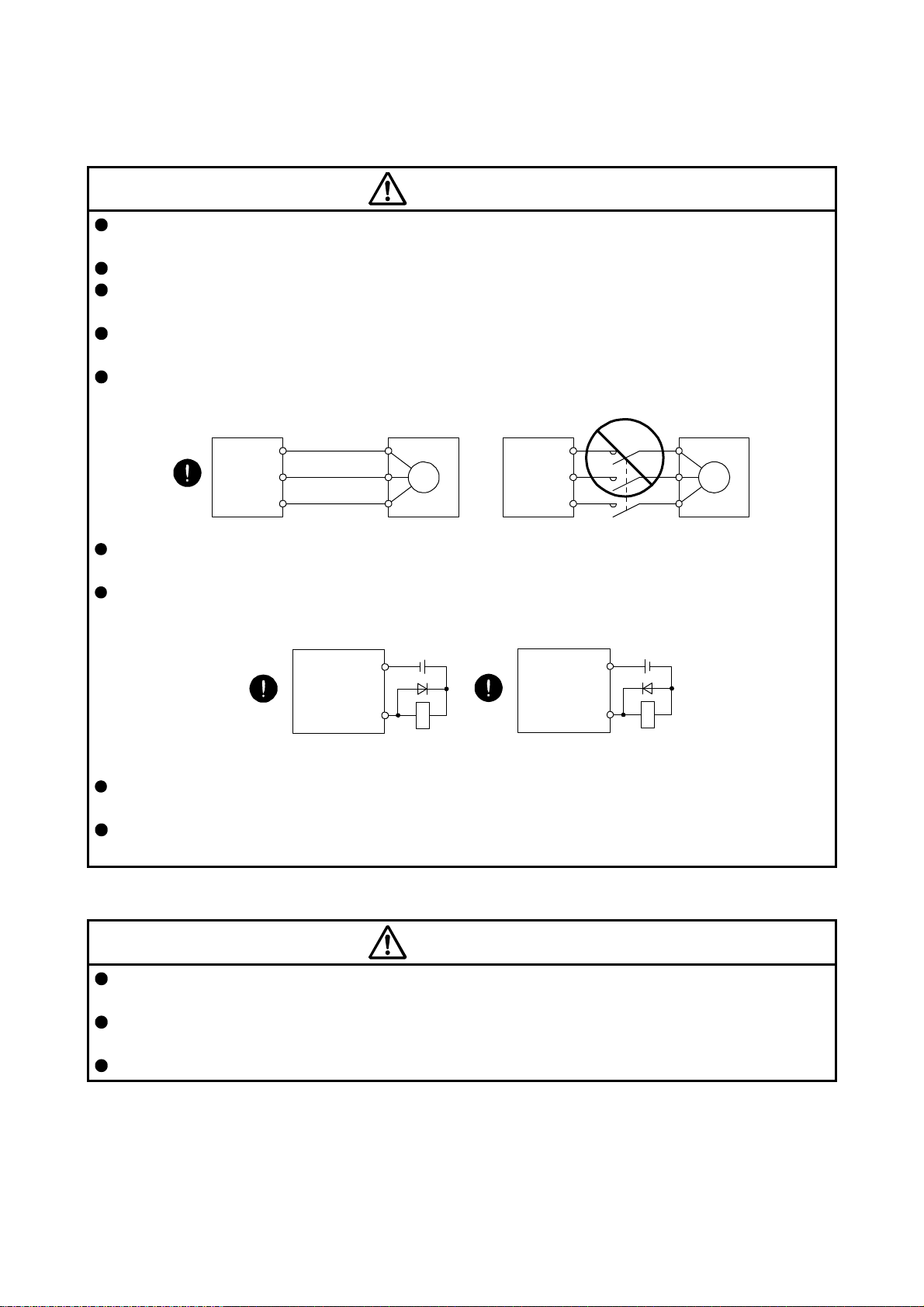
Connect the servo amplifier power output (U, V, and W) to the servo motor power input (U, V, and W)
directly. Do not let a magnetic contactor, etc. intervene. Otherwise, it may cause a malfunction.
Servo amplifier
U
V
W
Servo motor
U
V
W
Servo motorServo amplifier
U
M
V
W
U
V
W
M
The connection diagrams in this instruction manual are shown for sink interfaces, unless stated
otherwise.
The surge absorbing diode installed to the DC relay for control output should be fitted in the specified
direction. Otherwise, the emergency stop and other protective circuits may not operate.
Servo amplifier
DOCOM
Control output
signal
For sink output interface
24 V DC
RA
Servo amplifie
DOCOM
Control output
signal
For source output interface
24 V DC
RA
When the cable is not tightened enough to the terminal block, the cable or terminal block may generate
heat because of the poor contact. Be sure to tighten the cable with specified torque.
Connecting a servo motor of the wrong axis to U, V, W, or CN2 of the servo amplifier may cause a
malfunction.
(3) Test run and adjustment
CAUTION
Before operation, check the parameter settings. Improper settings may cause some machines to operate
unexpectedly.
Never make a drastic adjustment or change to the parameter values as doing so will make the operation
unstable.
Do not get close to moving parts during the servo-on status.
A - 4
(4) Usage
CAUTION
When it is assumed that a hazardous condition may occur due to a power failure or product malfunction,
use a servo motor with an external brake to prevent the condition.
Do not disassemble, repair, or modify the equipment.
Before resetting an alarm, make sure that the run signal of the servo amplifier is off in order to prevent a
sudden restart. Otherwise, it may cause an accident.
Use a noise filter, etc. to minimize the influence of electromagnetic interference. Electromagnetic
interference may be given to the electronic equipment used near the servo amplifier.
Burning or breaking a servo amplifier may cause a toxic gas. Do not burn or break it.
Use the servo amplifier with the specified servo motor.
The electromagnetic brake on the servo motor is designed to hold the motor shaft and should not be
used for ordinary braking.
For such reasons as service life and mechanical structure (e.g. where a ball screw and the servo motor
are coupled via a timing belt), the electromagnetic brake may not hold the motor shaft. To ensure safety,
install a stopper on the machine side.
(5) Corrective actions
CAUTION
When it is assumed that a hazardous condition may occur due to a power failure or product malfunction,
use a servo motor with an electromagnetic brake or external brake to prevent the condition.
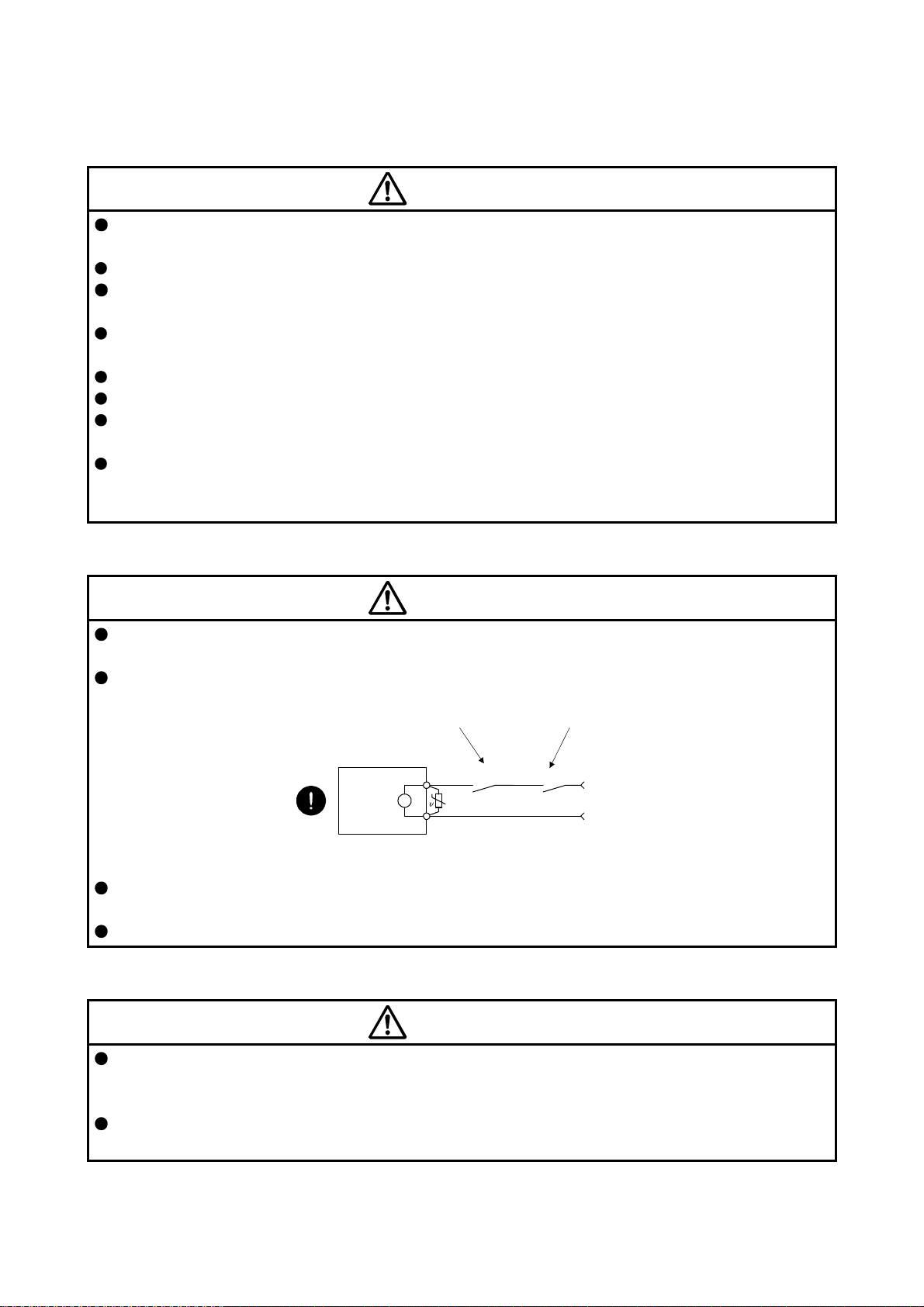
Configure an electromagnetic brake circuit so that it is activated also by an external EMG stop switch.
Contacts must be opened when ALM
(Malfunction) or MBR (Electromagnetic
brake interlock) turns off.
Servo motor
B
Electromagnetic brake
When any alarm has occurred, eliminate its cause, ensure safety, and deactivate the alarm before
restarting operation.
Provide an adequate protection to prevent unexpected restart after an instantaneous power failure.
Contacts must be opened
with the EMG stop switch.
RA
24 V DC
(6) Maintenance, inspection and parts replacement
CAUTION
With age, the electrolytic capacitor of the servo amplifier will deteriorate. To prevent a secondary
accident due to a malfunction, it is recommend that the electrolytic capacitor be replaced every 10 years
when it is used in general environment. For replacement, please contact your local sales office.
When using a servo amplifier whose power has not been turned on for a long time, contact your local
sales office.
A - 5
(7) General instruction
To illustrate details, the equipment in the diagrams of this Instruction Manual may have been drawn
without covers and safety guards. When the equipment is operated, the covers and safety guards must
be installed as specified. Operation must be performed in accordance with this Instruction Manual.
DISPOSAL OF WASTE
Please dispose a servo amplifier and other options according to your local laws and regulations.
EEP-ROM life
The number of write times to the EEP-ROM, which stores parameter settings, etc., is limited to 100,000. If
the total number of the following operations exceeds 100,000, the servo amplifier may malfunction when the
EEP-ROM reaches the end of its useful life.
Write to the EEP-ROM due to parameter setting changes
Write to the EEP-ROM due to device changes
Compliance with global standards
Refer to appendix 2 for the compliance with global standard.
Using HF-KN series and HF-SN series servo motors
For the combinations and characteristics when using HF-KN series and HF-SN series servo motors, refer to
appendix 5.
«About the manual»
You must have this Instruction Manual and the following manuals to use this servo. Ensure to prepare
them to use the servo safely.
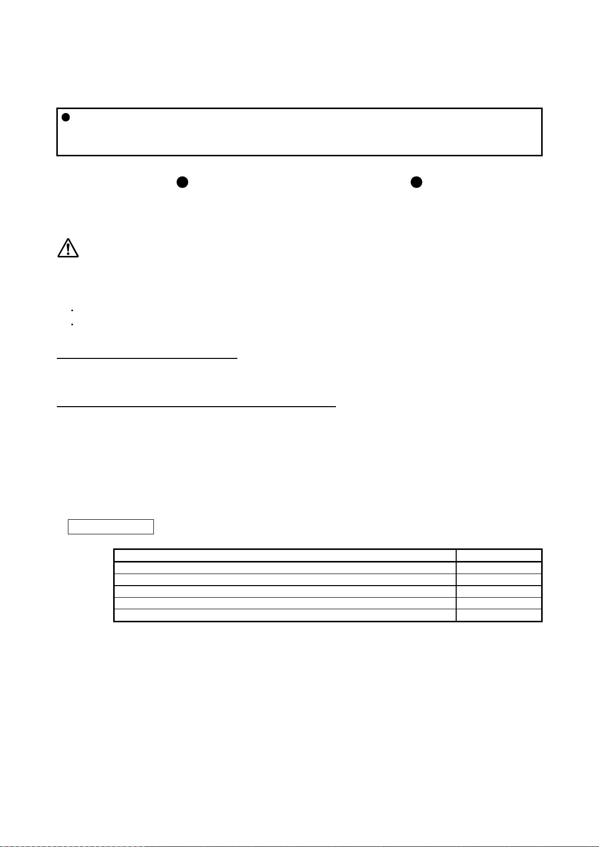
Relevant manuals
Manual name Manual No.
MELSERVO-JE Servo Amplifier Instruction Manual (Troubleshooting) SH(NA)030166
MELSERVO-JE-_A Servo Amplifier Instruction Manual (Positioning Mode) SH(NA)030150
MELSERVO-JE-_A Servo Amplifier Instruction Manual (Modbus-RTU Protocol) SH(NA)030177
MELSERVO HG-KN/HG-SN Servo Motor Instruction Manual SH(NA)030135
EMC Installation Guidelines IB(NA)67310
«Cables used for wiring»
Wires mentioned in this Instruction Manual are selected based on the ambient temperature of 40 ˚C.
A - 6

«U.S. customary units»
U.S. customary units are not shown in this manual. Convert the values if necessary according to the
following table.
Quantity SI (metric) unit U.S. customary unit
Mass 1 [kg] 2.2046 [lb]
Length 1 [mm] 0.03937 [inch]
Torque 1 [N•m] 141.6 [oz•inch]
Moment of inertia 1 [(× 10-4 kg•m2)] 5.4675 [oz•inch2]
Load (thrust load/axial load) 1 [N] 0.2248 [lbf]
Temperature N [°C] × 9/5 + 32 N [°F]
A - 7

MEMO
A - 8

CONTENTS
1. FUNCTIONS AND CONFIGURATION 1- 1 to 1-14
1.1 Summary ........................................................................................................................................... 1- 1
1.2 Function block diagram ..................................................................................................................... 1- 2
1.3 Servo amplifier standard specifications ............................................................................................ 1- 4
1.4 Combinations of servo amplifiers and servo motors ........................................................................ 1- 6
1.5 Function list ....................................................................................................................................... 1- 7
1.6 Model designation ............................................................................................................................. 1- 9
1.7 Structure .......................................................................................................................................... 1-10
1.7.1 Parts identification ..................................................................................................................... 1-10
1.8 Configuration including peripheral equipment ................................................................................. 1-12
2. INSTALLATION 2- 1 to 2- 6
2.1 Installation direction and clearances ................................................................................................ 2- 2
2.2 Keep out foreign materials ................................................................................................................ 2- 3
2.3 Encoder cable stress ........................................................................................................................ 2- 4
2.4 Inspection items ................................................................................................................................ 2- 4
2.5 Parts having service lives ................................................................................................................. 2- 5
3. SIGNALS AND WIRING 3- 1 to 3-66
3.1 Input power supply circuit ................................................................................................................. 3- 2
3.2 I/O signal connection example .......................................................................................................... 3- 7
3.2.1 Position control mode ................................................................................................................. 3- 7
3.2.2 Speed control mode .................................................................................................................. 3-12
3.2.3 Torque control mode ................................................................................................................. 3-14
3.3 Explanation of power supply system ............................................................................................... 3-16
3.3.1 Signal explanations ................................................................................................................... 3-16
3.3.2 Power-on sequence .................................................................................................................. 3-17
3.3.3 Wiring CNP1 and CNP2 ............................................................................................................ 3-18
3.4 Connectors and pin assignment ...................................................................................................... 3-20
3.5 Signal (device) explanations ............................................................................................................ 3-23
3.6 Detailed explanation of signals ........................................................................................................ 3-31
3.6.1 Position control mode ................................................................................................................ 3-31
3.6.2 Speed control mode .................................................................................................................. 3-36
3.6.3 Torque control mode ................................................................................................................. 3-38
3.6.4 Position/speed control switching mode ..................................................................................... 3-41
3.6.5 Speed/torque control switching mode ....................................................................................... 3-43
3.6.6 Torque/position control switching mode.................................................................................... 3-45
3.7 Forced stop deceleration function ................................................................................................... 3-46
3.7.1 Forced stop deceleration function ............................................................................................. 3-46
3.7.2 Base circuit shut-off delay time function ................................................................................... 3-48
3.7.3 Vertical axis freefall prevention function ................................................................................... 3-49
3.7.4 Residual risks of the forced stop function (EM2) ...................................................................... 3-49
3.8 Alarm occurrence timing chart ......................................................................................................... 3-50
3.8.1 When you use the forced stop deceleration function ................................................................ 3-50
3.8.2 When you do not use the forced stop deceleration function ..................................................... 3-51
1

3.9 Interfaces ......................................................................................................................................... 3-52
3.9.1 Internal connection diagram ...................................................................................................... 3-52
3.9.2 Detailed explanation of interfaces ............................................................................................. 3-54
3.9.3 Source I/O interfaces ................................................................................................................ 3-58
3.10 Servo motor with an electromagnetic brake .................................................................................. 3-60
3.10.1 Safety precautions .................................................................................................................. 3-60
3.10.2 Timing chart ............................................................................................................................ 3-62
3.11 Grounding ...................................................................................................................................... 3-65
4. STARTUP 4- 1 to 4-36
4.1 Switching power on for the first time ................................................................................................. 4- 1
4.1.1 Startup procedure ...................................................................................................................... 4- 1
4.1.2 Wiring check ............................................................................................................................... 4- 2
4.1.3 Surrounding environment ........................................................................................................... 4- 3
4.2 Startup in position control mode ....................................................................................................... 4- 4
4.2.1 Power on and off procedures ..................................................................................................... 4- 4
4.2.2 Stop ............................................................................................................................................ 4- 4
4.2.3 Test operation ............................................................................................................................ 4- 5
4.2.4 Parameter setting ....................................................................................................................... 4- 6
4.2.5 Actual operation ......................................................................................................................... 4- 6
4.2.6 Trouble at start-up ...................................................................................................................... 4- 7
4.3 Startup in speed control mode .......................................................................................................... 4- 9
4.3.1 Power on and off procedures ..................................................................................................... 4- 9
4.3.2 Stop ............................................................................................................................................ 4- 9
4.3.3 Test operation ........................................................................................................................... 4-10
4.3.4 Parameter setting ...................................................................................................................... 4-11
4.3.5 Actual operation ........................................................................................................................ 4-12
4.3.6 Trouble at start-up ..................................................................................................................... 4-12
4.4 Startup in torque control mode ........................................................................................................ 4-13
4.4.1 Power on and off procedures .................................................................................................... 4-13
4.4.2 Stop ........................................................................................................................................... 4-13
4.4.3 Test operation ........................................................................................................................... 4-14
4.4.4 Parameter setting ...................................................................................................................... 4-15
4.4.5 Actual operation ........................................................................................................................ 4-15
4.4.6 Trouble at start-up ..................................................................................................................... 4-16
4.5 Display and operation sections ........................................................................................................ 4-17
4.5.1 Summary .................................................................................................................
.................. 4-17
4.5.2 Display flowchart ....................................................................................................................... 4-18
4.5.3 Status display mode .................................................................................................................. 4-19
4.5.4 Diagnostic mode ....................................................................................................................... 4-23
4.5.5 Alarm mode ............................................................................................................................... 4-25
4.5.6 Parameter mode ....................................................................................................................... 4-26
4.5.7 External I/O signal display ......................................................................................................... 4-28
4.5.8 Output signal (DO) forced output .............................................................................................. 4-31
4.5.9 Test operation mode ................................................................................................................. 4-32
5. PARAMETERS 5- 1 to 5-46
5.1 Parameter list .................................................................................................................................... 5- 1
5.1.1 Basic setting parameters ([Pr. PA_ _ ]) ...................................................................................... 5- 1
2

5.1.2 Gain/filter setting parameters ([Pr. PB_ _ ]) ............................................................................... 5- 2
5.1.3 Extension setting parameters ([Pr. PC_ _ ]) .............................................................................. 5- 3
5.1.4 I/O setting parameters ([Pr. PD_ _ ]) ......................................................................................... 5- 5
5.1.5 Extension setting 2 parameters ([Pr. PE_ _ ]) ............................................................................ 5- 6
5.1.6 Extension setting 3 parameters ([Pr. PF_ _ ]) ............................................................................ 5- 7
5.2 Detailed list of parameters ................................................................................................................ 5- 8
5.2.1 Basic setting parameters ([Pr. PA_ _ ]) ...................................................................................... 5- 8
5.2.2 Gain/filter setting parameters ([Pr. PB_ _ ]) .............................................................................. 5-17
5.2.3 Extension setting parameters ([Pr. PC_ _ ]) ............................................................................. 5-28
5.2.4 I/O setting parameters ([Pr. PD_ _ ]) ........................................................................................ 5-39
5.2.5 Extension setting 2 parameters ([Pr. PE_ _ ]) ........................................................................... 5-44
5.2.6 Extension setting 3 parameters ([Pr. PF_ _ ]) ........................................................................... 5-44
6. NORMAL GAIN ADJUSTMENT 6- 1 to 6-24
6.1 Different adjustment methods ........................................................................................................... 6- 1
6.1.1 Adjustment on a single servo amplifier ...................................................................................... 6- 1
6.1.2 Adjustment using MR Configurator2 .......................................................................................... 6- 2
6.2 One-touch tuning .............................................................................................................................. 6- 3
6.2.1 One-touch tuning flowchart ........................................................................................................ 6- 3
6.2.2 Display transition and operation procedure of one-touch tuning ............................................... 6- 5
6.2.3 Caution for one-touch tuning ..................................................................................................... 6-13
6.3 Auto tuning ....................................................................................................................................... 6-14
6.3.1 Auto tuning mode ...................................................................................................................... 6-14
6.3.2 Auto tuning mode basis ............................................................................................................. 6-15
6.3.3 Adjustment procedure by auto tuning ....................................................................................... 6-16
6.3.4 Response level setting in auto tuning mode ............................................................................. 6-17
6.4 Manual mode ................................................................................................................................... 6-18
6.5 2 gain adjustment mode .................................................................................................................. 6-22
7. SPECIAL ADJUSTMENT FUNCTIONS 7- 1 to 7-28
7.1 Filter setting ...................................................................................................................................... 7- 1
7.1.1 Machine resonance suppression filter ....................................................................................... 7- 1
7.1.2 Adaptive filter II ........................................................................................................................... 7- 4
7.1.3 Shaft resonance suppression filter ............................................................................................. 7- 6
7.1.4 Low-pass filter ............................................................................................................................ 7- 7
7.1.5 Advanced vibration suppression control II ................................................................................. 7- 7
7.1.6 Command notch filter ................................................................................................................ 7-12
7.2 Gain switching function .................................................................................................................... 7-13
7.2.1 Applications ............................................................................................................................... 7-13
7.2.2 Function block diagram ............................................................................................................. 7-14
7.2.3 Parameter .................................................................................................................................. 7-15
7.2.4 Gain switching procedure ......................................................................................................... 7-17
7.3 Tough drive function ........................................................................................................................ 7-21
7.3.1 Vibration tough drive function.................................................................................................... 7-21
7.3.2 Instantaneous power failure tough drive function ..................................................................... 7-23
7.4 Model adaptive control disabled ...................................................................................................... 7-27
3

8. TROUBLESHOOTING 8- 1 to 8-8
8.1 Explanations of the lists .................................................................................................................... 8- 1
8.2 Alarm list ........................................................................................................................................... 8- 2
8.3 Warning list ....................................................................................................................................... 8- 6
9. DIMENSIONS 9- 1 to 9- 6
9.1 Servo amplifier .................................................................................................................................. 9- 1
9.2 Connector ......................................................................................................................................... 9- 4
10. CHARACTERISTICS 10- 1 to 10- 6
10.1 Overload protection characteristics .............................................................................................. 10- 1
10.2 Power supply capacity and generated loss .................................................................................. 10- 2
10.3 Dynamic brake characteristics ...................................................................................................... 10- 4
10.3.1 Dynamic brake operation ....................................................................................................... 10- 4
10.3.2 Permissible load to motor inertia when the dynamic brake is used ....................................... 10- 5
10.4 Cable bending life ......................................................................................................................... 10- 6
10.5 Inrush current at power-on ........................................................................................................... 10- 6
11. OPTIONS AND PERIPHERAL EQUIPMENT 11- 1 to 11-32
11.1 Cable/connector sets .................................................................................................................... 11- 1
11.1.1 Combinations of cable/connector sets ................................................................................... 11- 2
11.2 Regenerative option ...................................................................................................................... 11- 4
11.2.1 Combination and regenerative power .................................................................................... 11- 4
11.2.2 Selection of regenerative option ............................................................................................ 11- 5
11.2.3 Parameter setting ................................................................................................................... 11- 6
11.2.4 Selection of regenerative option ............................................................................................ 11- 7
11.2.5 Dimensions ........................................................................................................................... 11-11
11.3 Junction terminal block MR-TB50 ................................................................................................ 11-13
11.4 MR Configurator2 ........................................................................................................................ 11-15
11.4.1 Specifications ........................................................................................................................ 11-15
11.4.2 System requirements ............................................................................................................ 11-15
11.4.3 Precautions for using USB communication function ............................................................. 11-17
11.5 Selection example of wires .......................................................................................................... 11-18
11.6 Molded-case circuit breakers, fuses, magnetic contactors ......................................................... 11-19
11.7 Power factor improving AC reactor .............................................................................................. 11-20
11.8 Relay (recommended) ................................................................................................................. 11-21
11.9 Noise reduction techniques ......................................................................................................... 11-22
11.10 Earth-leakage current breaker ................................................................................................... 11-28
11.11 EMC filter (recommended) ........................................................................................................ 11-30
12. COMMUNICATION FUNCTION (MITSUBISHI GENERAL-PURPOSE AC SERVO PROTOCOL) 12- 1 to 12-34
12.1 Structure ....................................................................................................................................... 12- 1
12.1.1 Configuration diagram ............................................................................................................ 12- 1
12.1.2 Precautions for using RS422/USB communication function .................................................. 12- 2
12.2 Communication specifications ...................................................................................................... 12- 3
12.2.1 Outline of communication ...................................................................................................... 12- 3
4

12.2.2 Parameter setting ................................................................................................................... 12- 3
12.3 Protocol ......................................................................................................................................... 12- 4
12.3.1 Transmission data configuration ............................................................................................ 12- 4
12.3.2 Character codes ..................................................................................................................... 12- 5
12.3.3 Error codes ............................................................................................................................. 12- 6
12.3.4 Checksum .............................................................................................................................. 12- 6
12.3.5 Time-out processing............................................................................................................... 12- 6
12.3.6 Retry processing .................................................................................................................... 12- 7
12.3.7 Initialization ............................................................................................................................ 12- 7
12.3.8 Communication procedure example ...................................................................................... 12- 8
12.4 Command and data No. list .......................................................................................................... 12- 9
12.4.1 Reading command ................................................................................................................. 12- 9
12.4.2 Writing commands ................................................................................................................ 12-13
12.5 Detailed explanations of commands ............................................................................................ 12-15
12.5.1 Data processing .................................................................................................................... 12-15
12.5.2 Status display mode .............................................................................................................. 12-17
12.5.3 Parameter ............................................................................................................................. 12-18
12.5.4 External I/O signal status (DIO diagnosis) ............................................................................ 12-22
12.5.5 Input device on/off ................................................................................................................. 12-25
12.5.6 Disabling/enabling I/O devices (DIO) .................................................................................... 12-25
12.5.7 Input devices on/off (test operation) ...................................................................................... 12-26
12.5.8 Test operation mode ............................................................................................................. 12-27
12.5.9 Output signal pin on/off (output signal (DO) forced output) .................................................. 12-30
12.5.10 Alarm history ....................................................................................................................... 12-31
12.5.11 Current alarm ...................................................................................................................... 12-32
12.5.12 Software version ................................................................................................................. 12-33
APPENDIX App. - 1 to App. -17
App. 1 Peripheral equipment manufacturer (for reference) .............................................................. App.- 1
App. 2 Compliance with global standards ........................................................................................ App.- 1
App. 3 Analog monitor ..................................................................................................................... App.-11
App. 4 Low-voltage directive ........................................................................................................... App.-14
App. 5 Using HF-KN series and HF-SN series servo motors ......................................................... App.-15
App. 6 When turning on or off the input power supply with DC power supply ................................ App.-17
5

MEMO
6

1. FUNCTIONS AND CONFIGURATION
1. FUNCTIONS AND CONFIGURATION
1.1 Summary
The Mitsubishi general-purpose AC servo MELSERVO-JE series have limited functions with keeping high
performance based on MELSERVO-J4 series.
The servo amplifier has position, speed, and torque control modes. In the position control mode, the
maximum pulse train of 4 Mpulses/s is supported. Further, it can perform operation with the control modes
switched, e.g. position/speed control, speed/torque control and torque/position control. Hence, it is
applicable to a wide range of fields, not only precision positioning and smooth speed control of machine tools
and general industrial machines but also line control and tension control.
With one-touch tuning and real-time auto tuning, you can automatically adjust the servo gains according to
the machine.
The tough drive function, drive recorder function, and preventive maintenance support function strongly
support machine maintenance.
The servo amplifier has a USB communication interface. Therefore, you can connect the servo amplifier to
the personal computer with MR Configurator2 installed to perform the parameter setting, test operation, gain
adjustment, and others.
The MELSERVO-JE series servo motor equipped with an incremental encoder whose resolution is 131072
pulses/rev will enable a high-accuracy positioning.
1 - 1
1. FUNCTIONS AND CONFIGURATION
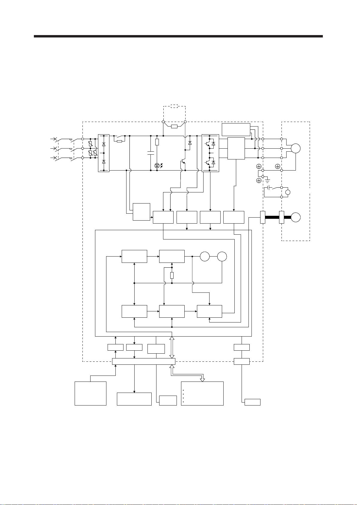
1.2 Function block diagram
The function block diagram of this servo is shown below.
(1) MR-JE-100A or less
Regenerative
option
(Note 2)
Power
supply
W
RA
24 V DC
Servo motor
U
V
B1
B
B2
Encoder
M
Electromagnetic
brake
P+
Diode
stack
MCMCCB
L1
U
L2
U U
L3
Relay
Position
command
input
Control
circuit
power
Model
position
control
Model position
(Note 1)
+
Regenerative
TR
CHARGE
lamp
Base
amplifier
Model
speed
control
Model speed Model torque
C
Voltage
detection
Overcurrent
protection
Virtual
motor
brake circuit
detection
Virtual
encoder
Dynamic
Current
encoder
Current
U
V
W
CN2
Analog
(2 channels)
Actual
position
control
CN1
Analog monitor
(2 channels)
RS-422/
RS-485
Actual
speed
control
Controller
RS-422/
RS-485
Current
I/F
D I/O control
Servo-on
Input command pulse.
Start
Malfunction, etc.
control
USBA/D D/A
CN3
Note 1. The built-in regenerative resistor is not provided for MR-JE-10A and MR-JE-20A.
2. For 1-phase 200 V AC to 240 V AC, connect the power supply to L1 and L3. Leave L2 open.
For the power supply specifications, refer to section 1.3.
Personal
computer
USB
1 - 2
1. FUNCTIONS AND CONFIGURATION
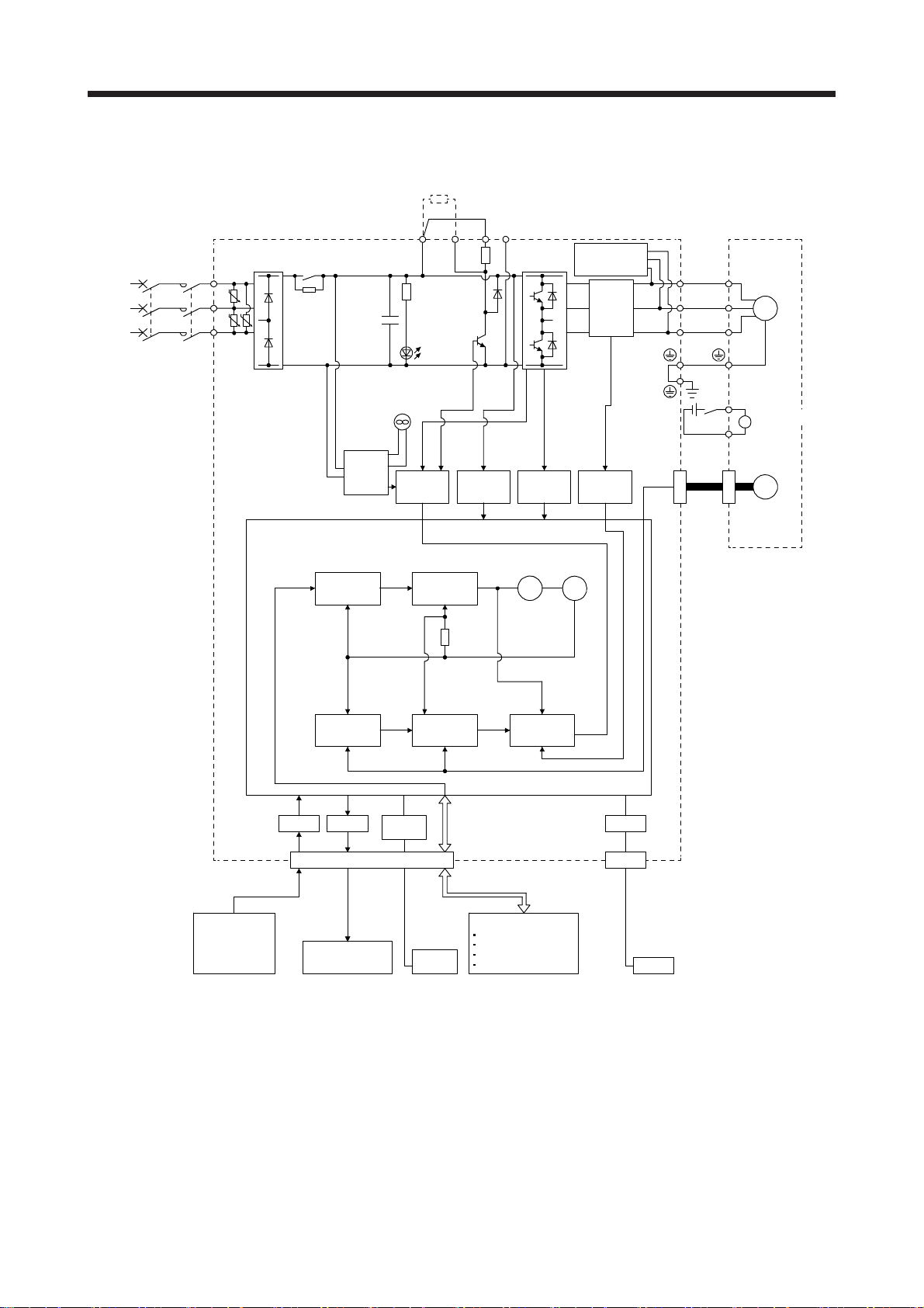
(2) MR-JE-200A or more
Regenerative
option
(Note 1)
Power
supply
W
RA
24 V DC
Servo motor
U
V
B1
B
B2
Encoder
M
Electromagnetic
brake
N- (Note 2)CDP+
Diode
stack
MCMCCB
L1
U
L2
U U
L3
Relay
Position
command
input
Control
circuit
power
Model
position
control
Model position
+
CHARGE
lamp
Cooling fan
Base
amplifier
Regenerative
TR
Voltage
detection
Model
speed
control
Model speed Model torque
Overcurrent
protection
Virtual
motor
brake circuit
detection
Virtual
encoder
Dynamic
Current
encoder
Current
U
V
W
CN2
Analog
(2 channels)
Actual
position
control
CN1
Analog monitor
(2 channels)
RS-422/
RS-485
Actual
speed
control
Controller
RS-422/
RS-485
Note 1. For the power supply specifications, refer to section 1.3.
2. This is for manufacturer adjustment. Leave this open.
Current
I/F
D I/O control
Servo-on
Input command pulse.
Start
Malfunction, etc.
control
USBA/D D/A
CN3
Personal
computer
USB
1 - 3
1. FUNCTIONS AND CONFIGURATION
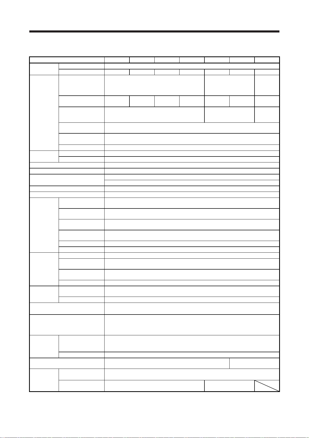
1.3 Servo amplifier standard specifications
Model: MR-JE- 10A 20A 40A 70A 100A 200A 300A
Output
Power supply
input
Interface
power supply
Control method Sine-wave PWM control, current control method
Dynamic brake Built-in
Communication function
Encoder output pulses Compatible (A/B/Z-phase pulse)
Analog monitor Two channels
Position
control mode
Speed control
mode
Torque
control mode
Positioning mode
Protective functions
Compliance
to global
standards
Structure (IP rating) Natural cooling, open (IP20)
Close
mounting
(Note 2)
Rated voltage 3-phase 170 V AC
Rated current [A] 1.1 1.5 2.8 5.8 6.0 11.0 11.0
Voltage/Frequency
Rated current
(Note 5)
Permissible voltage
fluctuation
Permissible frequency
fluctuation
Power supply capacity
[kVA]
Inrush current [A] Refer to section 10.5.
Voltage 24 V DC ± 10%
Current capacity [A] (Note 1) 0.3
Max. input pulse
frequency
Positioning feedback
pulse
Command pulse
multiplying factor
In-position range
setting
Error excessive ±3 revolutions
Torque limit Set by parameter setting or external analog input (0 V DC to +10 V DC/maximum torque)
Speed control range Analog speed command 1: 2000, internal speed command 1: 5000
Analog speed
command input
Speed fluctuation ratio
Torque limit Set by parameter setting or external analog input (0 V DC to +10 V DC/maximum torque)
Analog torque
command input
Speed limit Set by parameter setting or external analog input (0 V DC to 10 V DC/rated speed)
CE marking
UL standard UL 508C
3-phase power supply
input
1-phase power supply
input
3-phase or 1-phase 200 V AC to 240 V AC, 50
[A]
0.9 1.5 2.6 3.8 5.0 10.5 14.0
3-phase or 1-phase 170 V AC to 264 V AC
Within ±5%
Refer to section 10.2.
USB: connection to a personal computer or others (MR Configurator2-compatible)
RS-422/RS-485: Connection to controller (1: n communication up to 32 axes) (Note 4, 7)
4 Mpulses/s (for differential receiver) (Note 3), 200 kpulses/s (for open collector)
Encoder resolution (resolution per servo motor revolution): 131072 pulses/rev
Electronic gear A:1 to 16777215, B:1 to 16777215, 1/10 < A/B < 4000
0 to ±10 V DC/rated speed (The speed at 10 V is changeable with [Pr. PC12].)
±0.01% or less (load fluctuation 0% to 100%), 0% (power fluctuation ±10%), ±0.2% or less
(ambient temperature 25 °C ± 10 °C) when using analog speed command
0 V DC to ±8 V DC/maximum torque (input impedance 10 kΩ to 12 kΩ)
Refer to section 1.1 of "MR-JE-_A Servo Amplifier Instruction Manual (Positioning Mode)"
The positioning mode is available with servo amplifiers with software version B7 or later.
Overcurrent shut-off, regenerative overvoltage shut-off, overload shut-off (electronic thermal),
servo motor overheat protection, encoder error protection, regenerative error protection,
undervoltage protection, instantaneous power failure protection, overspeed protection, and
Possible
Possible Impossible
Hz/60 Hz
0 pulse to ±65535 pulses (command pulse unit)
error excessive protection
LVD: EN 61800-5-1
EMC: EN 61800-3
MD: EN ISO 13849-1, EN 61800-5-2, EN 62061
3-phase or 1-phase
200 V AC to 240 V AC,
50 Hz/60 Hz (Note 6)
3-phase or 1-phase
170 V AC to 264 V AC
(Note 6)
Force cooling, open
3-phase
200 V AC to
240 V AC,
50 Hz/60 Hz
3-phase
170 V AC to
264 V AC
(IP20)
1 - 4

1. FUNCTIONS AND CONFIGURATION
/s
Model: MR-JE- 10A 20A 40A 70A 100A 200A 300A
Ambient
temperature
Ambient
Environment
Mass [kg] 0.8 1.5 2.1
humidity
Ambience
Altitude 1000 m or less above sea level
Vibration resistance 5.9 m/s2, at 10 Hz to 55 Hz (directions of X, Y and Z axes)
Note 1. 0.3 A is the value applicable when all I/O signals are used. The current capacity can be decreased by reducing the number of
I/O points.
2. When closely mounting the servo amplifier of 3.5 kW or less, operate them at the ambient temperatures of 0 °C to 45 °C or at
75% or smaller effective load ratio.
3. 1 Mpulse/s or lower commands are supported in the initial setting. When inputting commands over 1 Mpulse/s and 4 Mpulses
or lower, change the setting in [Pr. PA13].
4. The RS-422 communication function is supported by servo amplifier manufactured in December 2013 or later. Refer to section
1.6 (1) for the year and month of manufacture.
5. These are current values for 3-phase power supply.
6. When using 1-phase 200 V AC to 240 V AC power supply, operate the servo amplifier at 75% or smaller effective load ratio.
7. The RS-485 communication function is available with servo amplifiers manufactured in May 2015 or later. Refer to section 1.6
(1) for the year and month of manufacture.
Operation 0 °C to 55 °C (non-freezing)
Storage -20 °C to 65 °C (non-freezing)
Operation
Storage
free from corrosive gas, flammable gas, oil mist, dust, and dirt
90 %RH or less (non-condensing)
Indoors (no direct sunlight),
1 - 5

1. FUNCTIONS AND CONFIGURATION
1.4 Combinations of servo amplifiers and servo motors
Servo amplifier Servo motor
MR-JE-10A HG-KN13_
MR-JE-20A HG-KN23_
MR-JE-40A HG-KN43_
MR-JE-70A HG-KN73_
MR-JE-100A HG-SN102_
MR-JE-200A HG-SN152_
MR-JE-300A HG-SN302_
HG-SN52_
HG-SN202_
1 - 6
1. FUNCTIONS AND CONFIGURATION
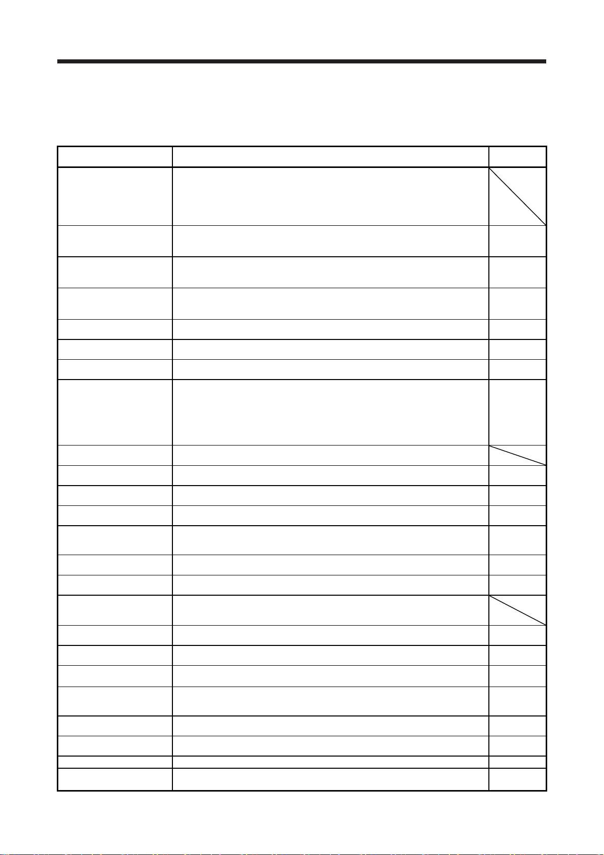
1.5 Function list
The following table lists the functions of this servo. For details of the functions, refer to each section
indicated in the detailed explanation field.
Function Description
This function achieves a high response and stable control following the ideal model.
The two-degree-of-freedom-model model adaptive control enables you to set a
Model adaptive control
Position control mode This servo is used as a position control servo.
Speed control mode This servo is used as a speed control servo.
Torque control mode This servo is used as a torque control servo.
Position/speed control switch
mode
Speed/torque control switch
mode
Torque/position control switch
mode
Positioning mode
High-resolution encoder
Gain switching function
Advanced vibration
suppression control II
Machine resonance
suppression filter
Shaft resonance suppression
filter
Adaptive filter II
Low-pass filter
Machine analyzer function
Robust filter
Slight vibration suppression
control
Electronic gear Input pulses can be multiplied by 1/10 to 4000.
S-pattern
acceleration/deceleration time
constant
Auto tuning
Regenerative option
Alarm history clear Alarm history is cleared. [Pr. PC18]
Output signal selection
(device settings)
response to the command and response to the disturbance separately.
Additionally, this function can be disabled. Refer to section 7.4 for disabling this
function. Used by servo amplifiers with software version B4 or later. Check the
software version using MR Configurator2.
Using an input device, control can be switched between position control and speed
control.
Using an input device, control can be switched between speed control and torque
control.
Using an input device, control can be switched between torque control and position
control.
In this mode, MR-JE-_A servo amplifiers are used in with point table or program
method. For details, refer to "MR-JE-_A Servo Amplifier Instruction Manual
(Positioning Mode)." The positioning mode is available with servo amplifiers with
software version B7 or later.
High-resolution encoder of 131072 pulses/rev is used for the encoder of the servo
motor compatible with the MELSERVO-JE series.
You can switch gains during rotation and during stop, and can use an input device to
switch gains during operation.
This function suppresses vibration at the arm end or residual vibration. Section 7.1.5
This is a filter function (notch filter) which decreases the gain of the specific frequency
to suppress the resonance of the mechanical system.
When a load is mounted to the servo motor shaft, resonance by shaft torsion during
driving may generate a mechanical vibration at high frequency. The shaft resonance
suppression filter suppresses the vibration.
Servo amplifier detects mechanical resonance and sets filter characteristics
automatically to suppress mechanical vibration.
Suppresses high-frequency resonance which occurs as servo system response is
increased.
Analyzes the frequency characteristic of the mechanical system by simply connecting
an MR Configurator2 installed personal computer and servo amplifier.
MR Configurator2 is necessary for this function.
This function provides better disturbance response in case low response level that
load to motor inertia ratio is high for such as roll send axes.
Suppresses vibration of ±1 pulse produced at a servo motor stop. [Pr. PB24]
Speed can be increased and decreased smoothly. [Pr. PC03]
Automatically adjusts the gain to optimum value if load applied to the servo motor
shaft varies.
Used when the built-in regenerative resistor of the servo amplifier does not have
sufficient regenerative capability for the regenerative power generated.
ST1 (Forward rotation start), ST2 (Reverse rotation start), and SON (Servo-on) and
other input device can be assigned to any pins.
Detailed
explanation
Section 3.2.1
Section 3.6.1
Section 4.2
Section 3.2.2
Section 3.6.2
Section 4.3
Section 3.2.3
Section 3.6.3
Section 4.4
Section 3.6.4
Section 3.6.5
Section 3.6.6
MR-JE-_A
Servo
Amplifier
Instruction
Manual
(Positioning
Mode)
Section 7.2
Section 7.1.1
Section 7.1.3
Section 7.1.2
Section 7.1.4
[Pr. PE41]
[Pr. PA06]
[Pr. PA07]
Section 6.3
Section 11.2
[Pr. PD03] to
[Pr. PD20]
1 - 7
1. FUNCTIONS AND CONFIGURATION
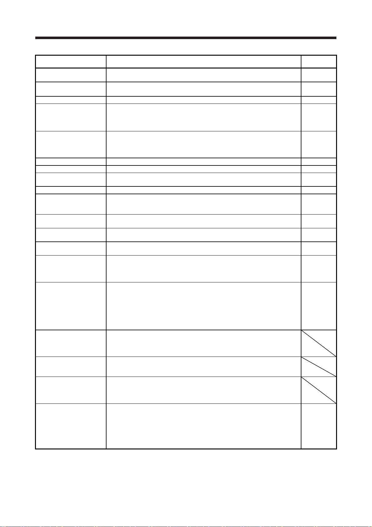
Function Description
Output signal selection
(device settings)
Output signal (DO) forced
output
Command pulse selection Command pulse train form can be selected from among three different types. [Pr. PA13]
Torque limit Servo motor torque can be limited to any value.
Speed limit Servo motor speed can be limited to any value.
Status display Servo status is shown on the 5-digit, 7-segment LED display. Section 4.5.3
External I/O signal display On/off statuses of external I/O signals are shown on the display. Section 4.5.7
Automatic VC offset
Alarm code output If an alarm has occurred, the corresponding alarm number is outputted in 3-bit code. Chapter 8
Test operation mode
Analog monitor output Servo status is outputted in terms of voltage in real time.
MR Configurator2
One-touch tuning
Tough drive function
Drive recorder function
Servo amplifier life diagnosis
function
Power monitoring function
Machine diagnosis function
Modbus-RTU communication
function
The output devices including MBR (Electromagnetic brake interlock) can be assigned
to certain pins of the CN1 connector.
Output signal can be forced on/off independently of the servo status.
Use this function for checking output signal wiring, etc.
Voltage is automatically offset to stop the servo motor if it does not come to a stop
when VC (Analog speed command) or VLA (Analog speed limit is 0 V.
Jog operation, positioning operation, motor-less operation, DO forced output, and
program operation
MR Configurator2 is required for the positioning operation and program operation.
Using a personal computer, you can perform the parameter setting, test operation,
monitoring, and others.
Gain adjustment is performed just by one click on a certain button on MR
Configurator2 or operation section.
This function makes the equipment continue operating even under the condition that
an alarm occurs.
The tough drive function includes two types: the vibration tough drive and the
instantaneous power failure tough drive.
This function continuously monitors the servo status and records the status transition
before and after an alarm for a fixed period of time. You can check the recorded data
on the drive recorder window on MR Configurator2 by clicking the "Graph" button.
However, the drive recorder will not operate on the following conditions.
1. You are using the graph function of MR Configurator2.
2. You are using the machine analyzer function.
3. [Pr. PF21] is set to "-1".
You can check the cumulative energization time and the number of on/off times of the
inrush relay. This function gives an indication of the replacement time for parts of the
servo amplifier including a capacitor and a relay before they malfunction.
MR Configurator2 is necessary for this function.
This function calculates the power running energy and the regenerative power from
the data in the servo amplifier such as speed and current. Power consumption and
others are displayed on MR Configurator2.
From the data in the servo amplifier, this function estimates the friction and vibrational
component of the drive system in the equipment and recognizes an error in the
machine parts, including a ball screw and bearing.
MR Configurator2 is necessary for this function.
The Modbus protocol uses dedicated message frames for the serial communication
between a master and slaves. The dedicated message frames have functions for
reading and writing data, and users can write parameters from servo amplifiers and
check the operation status of the servo amplifiers by using this function.
Detailed
explanation
[Pr. PD24] to
[Pr. PD28]
Section 4.5.8
Section 3.6.1
(5)
[Pr. PA11]
[Pr. PA12]
Section 3.6.3
(3)
[Pr. PC05] to
[Pr. PC11]
Section 4.5.4
Section 4.5.9
[Pr. PC14],
[Pr. PC15]
Section 11.4
Section 6.2
Section 7.3
[Pr. PA23]
MR-JE-_A
Servo
Amplifier
Instruction
Manual
(Modbus-RTU
Protocol)
1 - 8
1. FUNCTIONS AND CONFIGURATION
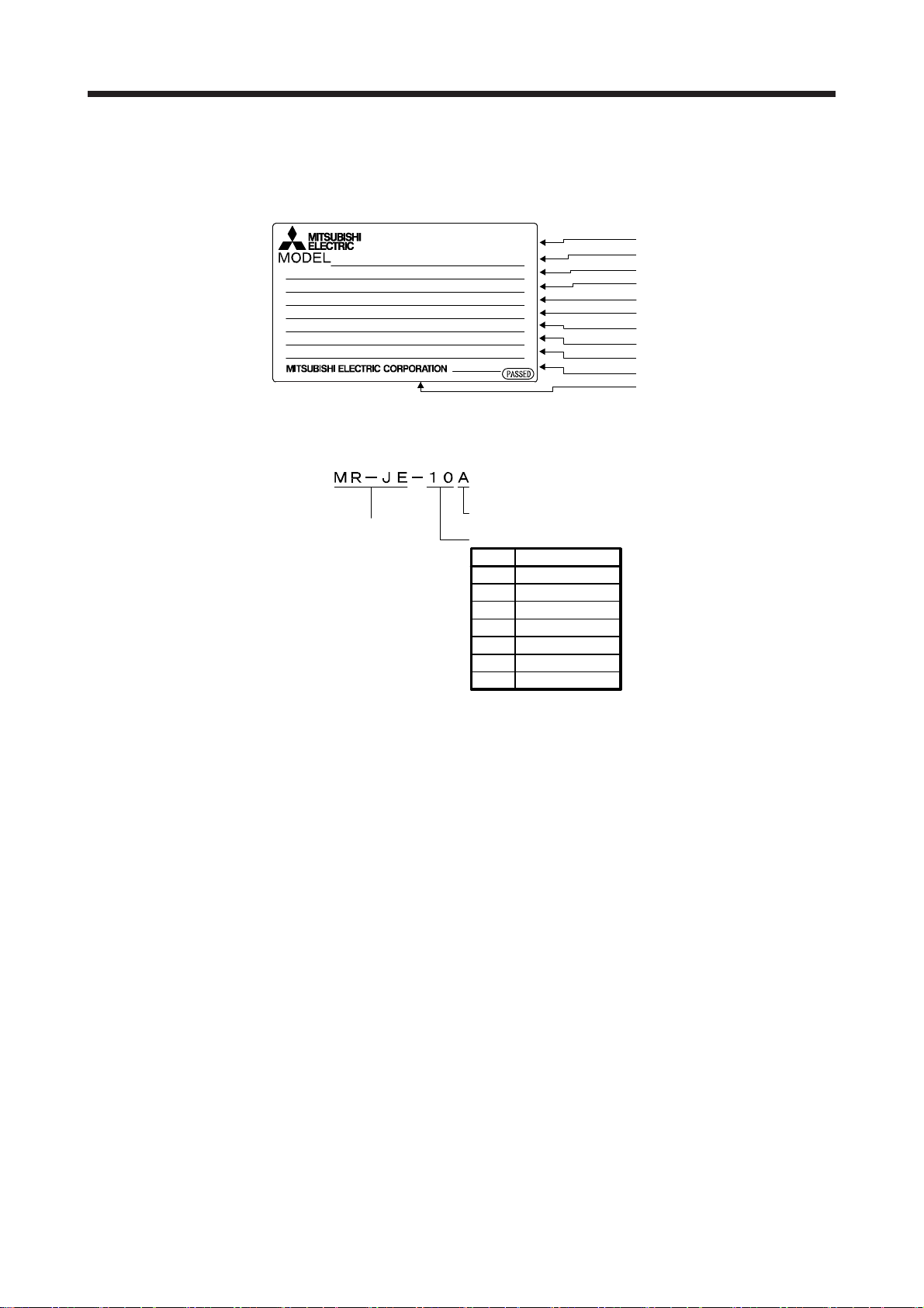
1.6 Model designation
(1) Rating plate
The following shows an example of rating plate for explanation of each item.
AC SERVO
SER. S4Y001001
MR-JE-10A
POWER
: 100W
INPUT
: 3AC/200-240V 0.9A/1.5A 50/60Hz
OUTPUT
: 3PH170V 0-360Hz 1.1A
STD.: IEC/EN61800-5-1 MAN.: IB(NA)0300194
Max. Surrounding Air Temp.: 55°C
IP20
KCC-REI-MEK-TC300A745G51
TOKYO 100-8310, JAPAN MADE IN JAPAN
DATE: 2014-11
(2) Model
The following describes what each block of a model name indicates.
General-purpose interface
Series
Rated output
Symbol Rated output [kW]
10 0.1
20 0.2
40 0.4
70 0.75
100 1
200 2
300 3
Serial number
Model
Capacity
Applicable power supply
Rated output current
Standard, Manual number
Ambient temperature
IP rating
KC certification number
The year and month of manufacture
Country of origin
1 - 9
1. FUNCTIONS AND CONFIGURATION
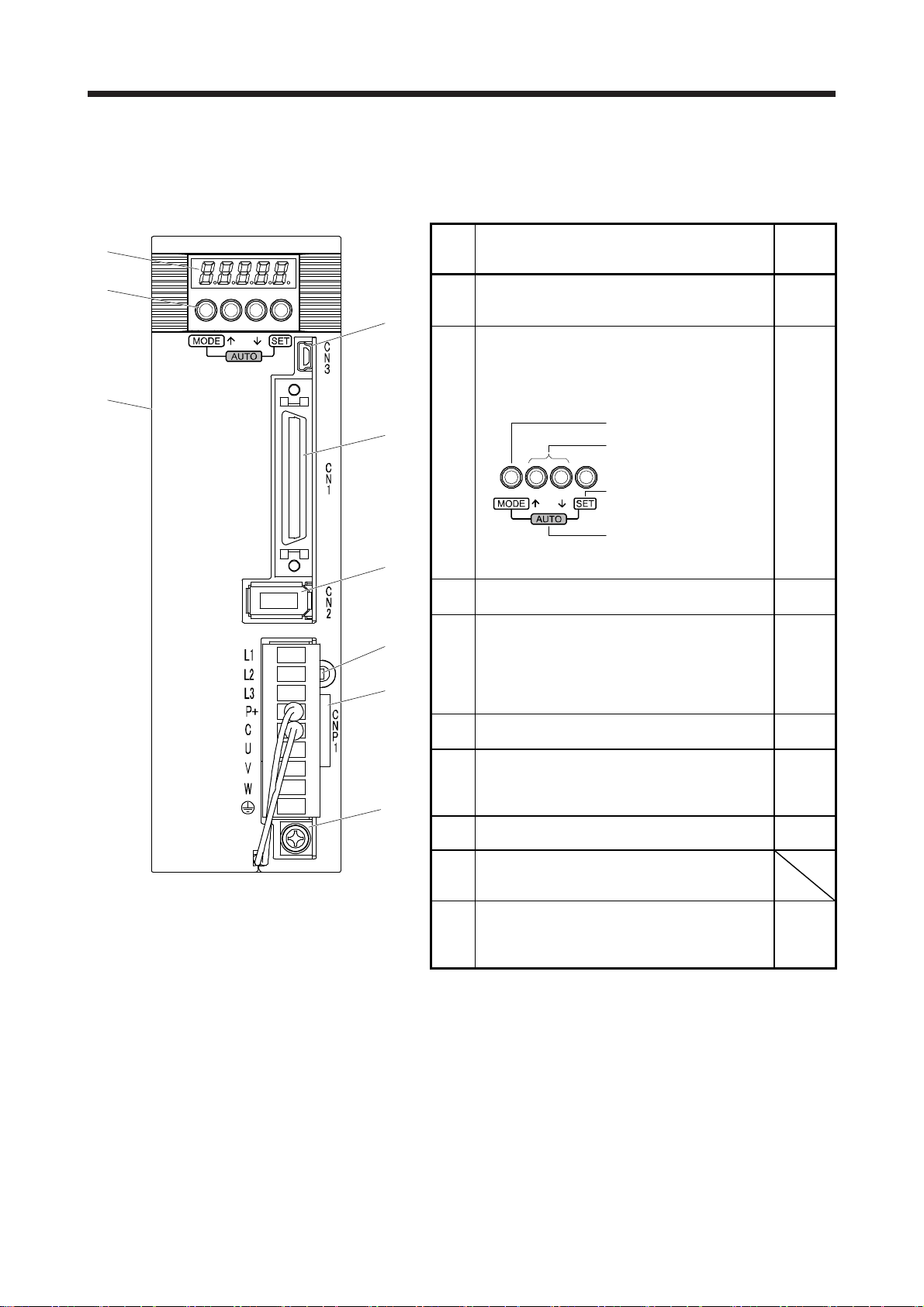
1.7 Structure
1.7.1 Parts identification
(1) MR-JE-100A or less
(1)
(2)
(3)
(7)
Side
(4)
No. Name/Application
(1)
(2)
Display
The 5-digit, 7-segment LED shows the servo status
and the alarm number.
Operation section
Used to perform status display, diagnostic, alarm,
and parameter setting operations. Push the "MODE"
and "SET" buttons at the same time for 3 s or more
to switch to the one-touch tuning mode.
Used to change the mode.
Used to change the
display or data in each
mode.
Used to set data.
Detailed
explanati
on
Section
4.5
Section
4.5
Section
6.2
To the one-touch tuning
mode
Section
11.4
Section
3.2
Section
3.4
Chapter
12
Section
3.4
Section
3.1
Section
3.3
1.6
Section
3.1
Section
3.3
Bottom
(9)
(5)
(8)
(6)
USB communication connector (CN3)
(3)
Connect with the personal computer.
I/O signal connector (CN1)
Digital I/O signal, analog input signal, analog
monitor output signal, and RS-422/RS-485
(4)
communication controller are connected.
Encoder connector (CN2)
(5)
Used to connect the servo motor encoder.
Power connector (CNP1)
Input power supply, built-in regenerative resistor,
(6)
regenerative option, and servo motor are connected.
Rating plate Section
(7)
Charge lamp
(8)
When the main circuit is charged, this will light up.
While this lamp is lit, do not reconnect the cables.
Protective earth (PE) terminal
Grounding terminal
(9)
1 - 10
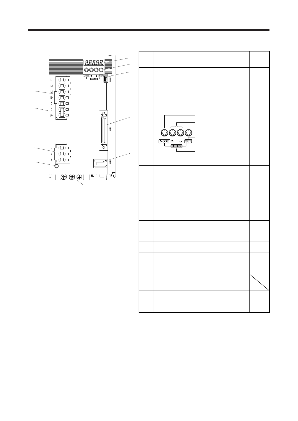
1. FUNCTIONS AND CONFIGURATION
(2) MR-JE-200A or more
(1)
No. Name/Application
(2)
(3)
(1)
(6)
(7)
Side
(4)
(2)
Display
The 5-digit, 7-segment LED shows the servo status
and the alarm number.
Operation section
Used to perform status display, diagnostic, alarm,
and parameter setting operations. Push the "MODE"
and "SET" buttons at the same time for 3 s or more
to switch to the one-touch tuning mode.
Used to change the mode.
Used to change the
display or data in each
mode.
Used to set data.
Detailed
explanati
on
Section
4.5
Section
4.5
Section
6.2
(8)
(9)
(10)
Bottom
(5)
To the one-touch tuning
mode
USB communication connector (CN3)
(3)
Connect with the personal computer.
I/O signal connector (CN1)
Digital I/O signal, analog input signal, analog
monitor output signal, and RS-422/RS-485
(4)
communication controller are connected.
Encoder connector (CN2)
(5)
Used to connect the servo motor encoder.
Power connector (CNP1)
Input power supply and regenerative option are
(6)
connected.
Rating plate Section
(7)
Servo motor power connector (CNP2)
Connect the servo motor.
(8)
Charge lamp
(9)
When the main circuit is charged, this will light up.
While this lamp is lit, do not reconnect the cables.
Protective earth (PE) terminal
Grounding terminal
(10)
Section
11.4
Section
3.2
Section
3.4
Chapter
12
Section
3.4
Section
3.1
Section
3.3
1.6
Section
3.1
Section
3.3
Section
3.1
Section
3.3
1 - 11
1. FUNCTIONS AND CONFIGURATION
A
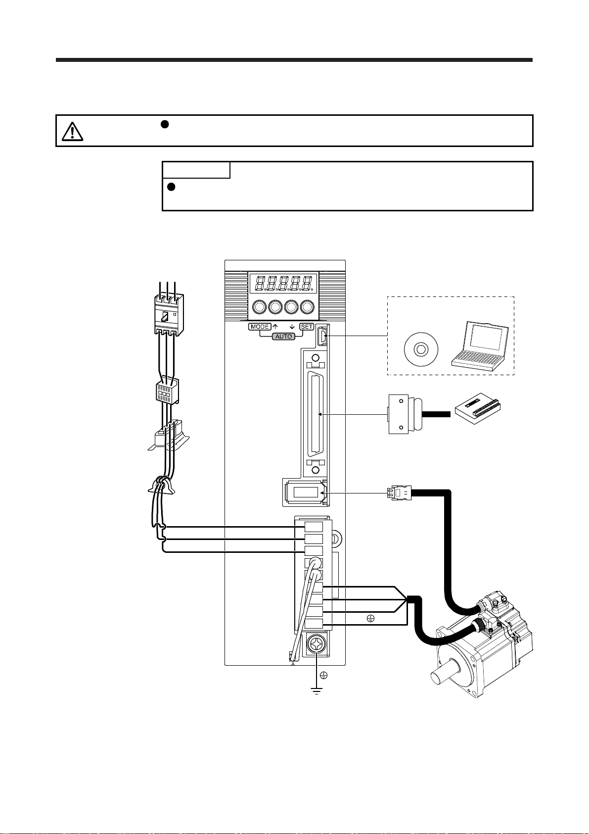
1.8 Configuration including peripheral equipment
CAUTION
(1) MR-JE-100A or less
The diagram shows MR-JE-40A.
Connecting a servo motor of the wrong axis to U, V, W, or CN2 of the servo
amplifier may cause a malfunction.
POINT
Equipment other than the servo amplifier and servo motor are optional or
recommended products.
(Note 1)
Power
supply
Molded-case
circuit breaker
(Note 2)
Magnetic
contactor
(MC)
Power factor
improving AC
reactor
(FR-HAL)
Line noise
filter
(FR-BSF01)
RST
Personal
computer
MR Configurator2
CN3
CN1
Junction terminal block
CN2
L1
L2
L3
U
V
W
Note 1. A 1-phase 200 V AC to 240 V AC power supply may be used with the servo amplifier of MR-JE-70A or less. For 1-phase 200 V
C to 240 V AC, connect the power supply to L1 and L3. Leave L2 open. For the power supply specifications, refer to section
1.3.
2. Depending on the power supply voltage and operation pattern, bus voltage can decrease. This can shift the mode to the
dynamic brake deceleration during forced stop deceleration. When dynamic brake deceleration is not required, slow the time to
turn off the magnetic contactor.
Servo motor
1 - 12
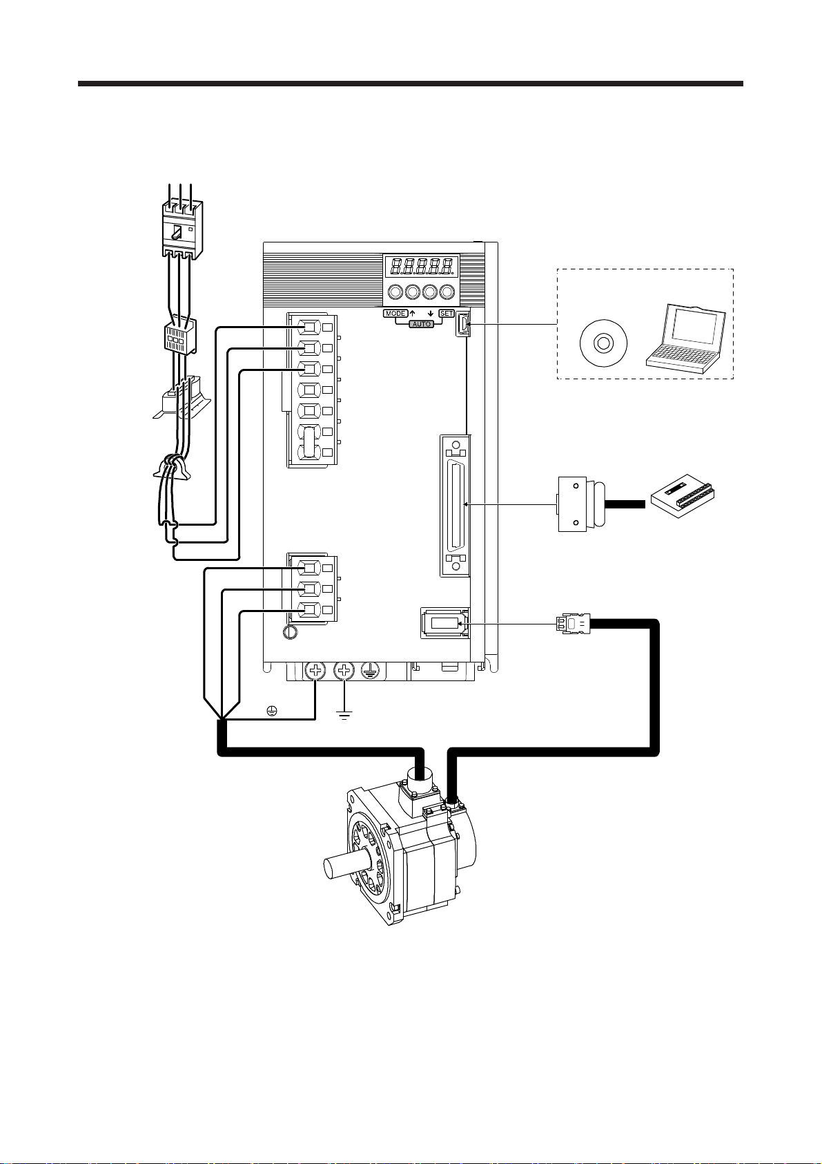
1. FUNCTIONS AND CONFIGURATION
(2) MR-JE-200A or more
The diagram shows MR-JE-200A.
(Note 1)
Power
supply
Molded-case
circuit breaker
(Note 2)
Magnetic
contactor
(MC)
Power factor
improving AC
reactor
(FR-HAL)
Line noise
filter
(FR-BSF01)
RS T
CN3
MR Configurator2
Personal
computer
L1
L2
L3
CN1
Junction terminal block
U
V
W
CN2
Servo motor
Note 1. For the power supply specifications, refer to section 1.3.
2. Depending on the power supply voltage and operation pattern, bus voltage can decrease. This can shift the mode to the
dynamic brake deceleration during forced stop deceleration. When dynamic brake deceleration is not required, slow the time to
turn off the magnetic contactor.
1 - 13

1. FUNCTIONS AND CONFIGURATION
MEMO
1 - 14
2. INSTALLATION
2. INSTALLATION
WARNING
CAUTION
To prevent electric shock, ground each equipment securely.
Stacking in excess of the specified number of product packages is not allowed.
Do not hold the lead wire of the regenerative resistor when transporting the servo
amplifier.
Install the equipment on incombustible material. Installing them directly or close to
combustibles will lead to a fire.
Install the servo amplifier and the servo motor in a load-bearing place in
accordance with the Instruction Manual.
Do not get on or put heavy load on the equipment. Otherwise, it may cause injury.
Use the equipment within the specified environment. For the environment, refer to
section 1.3.
Provide an adequate protection to prevent screws and other conductive matter, oil
and other combustible matter from entering the servo amplifier.
Do not block the intake and exhaust areas of the servo amplifier. Otherwise, it
may cause a malfunction.
Do not drop or strike the servo amplifier. Isolate it from all impact loads.
Do not install or operate the servo amplifier which has been damaged or has any
parts missing.
When the product has been stored for an extended period of time, contact your
local sales office.
When handling the servo amplifier, be careful about the edged parts such as
corners of the servo amplifier.
The servo amplifier must be installed in a metal cabinet.
When fumigants that contain halogen materials such as fluorine, chlorine,
bromine, and iodine are used for disinfecting and protecting wooden packaging
from insects, they cause malfunction when entering our products. Please take
necessary precautions to ensure that remaining materials from fumigant do not
enter our products, or treat packaging with methods other than fumigation (heat
method). Additionally, disinfect and protect wood from insects before packing
products.
2 - 1

2. INSTALLATION
2.1 Installation direction and clearances
The equipment must be installed in the specified direction. Otherwise, it may
CAUTION
MR-JE-40A to MR-JE-100A have a regenerative resistor on their back face. The regenerative resistor
generates heat of 100 ˚C higher than the ambient temperature. Please fully consider heat dissipation,
installation position, etc. when mounting it.
(1) Installation clearances of the servo amplifier
(a) Installation of one servo amplifier
10 mm
or more
cause a malfunction.
Leave specified clearances between the servo amplifier and the cabinet walls or
other equipment. Otherwise, it may cause a malfunction.
Cabinet Cabinet
40 mm
or more
Servo
amplifier
10 mm
or more
Wiring allowance
80 mm
or more
Top
Bottom
40 mm
or more
2 - 2

2. INSTALLATION
(b) Installation of two or more servo amplifiers
POINT
Close mounting is possible depending on the capacity of the servo amplifier.
Refer to section 1.3 for availability of close mounting.
Leave a large clearance between the top of the servo amplifier and the cabinet walls, and install a
cooling fan to prevent the internal temperature of the cabinet from exceeding the environment.
When mounting the servo amplifiers closely, leave a clearance of 1 mm between the adjacent servo
amplifiers in consideration of mounting tolerances. In this case, keep the ambient temperature within
0 ˚C to 45 ˚C or use the servo amplifier with 75% or less of the effective load ratio.
Cabinet
Cabinet
30 mm
or more
100 mm or more
10 mm or more
30 mm
or more
40 mm or more
Leaving clearance Mounting closely
1 mm
100 mm or more
1 mm
40 mm or more
(2) Others
When using heat generating equipment such as the regenerative option, install them with full
consideration of heat generation so that the servo amplifier is not affected.
Install the servo amplifier on a perpendicular wall in the correct vertical direction.
2.2 Keep out foreign materials
30 mm
or more
Top
Bottom
(1) When drilling in the cabinet, prevent drill chips and wire fragments from entering the servo amplifier.
(2) Prevent oil, water, metallic dust, etc. from entering the servo amplifier through openings in the cabinet or
a cooling fan installed on the ceiling.
(3) When installing the cabinet in a place where toxic gas, dirt and dust exist, conduct an air purge (force
clean air into the cabinet from outside to make the internal pressure higher than the external pressure) to
prevent such materials from entering the cabinet.
2 - 3

2. INSTALLATION
2.3 Encoder cable stress
(1) The way of clamping the cable must be fully examined so that bending stress and cable's own weight
stress are not applied to the cable connection.
(2) For use in any application where the servo motor moves, fix the cables (encoder, power supply, and
brake) with having some slack from the connector connection part of the servo motor to avoid putting
stress on the connector connection part. Use the optional encoder cable within the bending life range.
Use the power supply and brake wiring cables within the bending life of the cables.
(3) Avoid any probability that the cable sheath might be cut by sharp chips, rubbed by a machine corner or
stamped by workers or vehicles.
(4) For installation on a machine where the servo motor moves, the flexing radius should be made as large
as possible. Refer to section 10.4 for the bending life.
2.4 Inspection items
Before starting maintenance and/or inspection, turn off the power and wait for 15
minutes or more until the charge lamp turns off. Otherwise, an electric shock may
WARNING
CAUTION
It is recommended that the following points periodically be checked.
(1) Check for loose terminal block screws. Retighten any loose screws.
(2) Check the cables and the like for scratches or cracks. Inspect them periodically according to operating
conditions especially when the servo motor is movable.
(3) Check that the connector is securely connected to the servo amplifier.
(4) Check that the wires are not coming out from the connector.
(5) Check for dust accumulation on the servo amplifier.
(6) Check for unusual noise generated from the servo amplifier.
occur. In addition, when confirming whether the charge lamp is off or not, always
confirm it from the front of the servo amplifier.
To avoid an electric shock, only qualified personnel should attempt inspections.
For repair and parts replacement, contact your local sales office.
Do not perform insulation resistance test on the servo amplifier. Otherwise, it may
cause a malfunction.
Do not disassemble and/or repair the equipment on customer side.
2 - 4

2. INSTALLATION
2.5 Parts having service lives
Service lives of the following parts are listed below. However, the service life vary depending on operating
methods and environment. If any fault is found in the parts, they must be replaced immediately regardless of
their service lives. For parts replacement, please contact your local sales office.
(1) Smoothing capacitor
The characteristic of smoothing capacitor is deteriorated due to ripple currents, etc. The life of the
capacitor greatly depends on ambient temperature and operating conditions. The capacitor will reach
the end of its life in 10 years of continuous operation in normal air-conditioned environment (40 ˚C
surrounding air temperature or less).
(2) Relays
Contact faults will occur due to contact wear arisen from switching currents. Relays will reach the end of
their lives depending on their power supply capacity when the number of power-on times and number of
forced stop times by EM1 (Forced stop 1) are 100,000 times in total.
(3) Servo amplifier cooling fan
The cooling fan bearings reach the end of their life in 50,000 hours to 70,000 hours. Normally, therefore,
the cooling fan must be replaced in seven to eight years of continuous operation as a guideline. It must
also be changed if unusual noise or vibration is found during inspection.
The life indicates under the yearly average ambient temperature of 40 ˚C, free from corrosive gas,
flammable gas, oil mist, dust and dirt.
Part name Life guideline
Smoothing capacitor 10 years
Relay
Cooling fan
Number of power-on and forced stop times
by EM1 (Forced stop 1): 100,000 times
50,000 hours to 70,000 hours (7 years to 8
years)
2 - 5

2. INSTALLATION
MEMO
2 - 6

3. SIGNALS AND WIRING
r
3. SIGNALS AND WIRING
Any person who is involved in wiring should be fully competent to do the work.
Before wiring, turn off the power and wait for 15 minutes or more until the charge
lamp turns off. Otherwise, an electric shock may occur. In addition, when
confirming whether the charge lamp is off or not, always confirm it from the front
of the servo amplifier.
WARNING
Ground the servo amplifier and servo motor securely.
Do not attempt to wire the servo amplifier and servo motor until they have been
installed. Otherwise, it may cause an electric shock.
The cables should not be damaged, stressed, loaded, or pinched. Otherwise, it
may cause an electric shock.
To avoid an electric shock, insulate the connections of the power supply
terminals.
Before removing the CNP1 connector from MR-JE-40A to MR-JE-100A,
disconnect the lead wires of the regenerative resistor from the CNP1 connector.
Wire the equipment correctly and securely. Otherwise, the servo motor may
operate unexpectedly, resulting in injury.
Connect cables to the correct terminals. Otherwise, a burst, damage, etc. may
occur.
Ensure that polarity (+/-) is correct. Otherwise, a burst, damage, etc. may occur.
The surge absorbing diode installed to the DC relay for control output should be
fitted in the specified direction. Otherwise, the emergency stop and other
protective circuits may not operate.
Servo amplifier
DOCOM
24 V DC
Servo amplifie
24 V DC
DOCOM
CAUTION
Control output
signal
For sink output interface
RA
Control output
signal
For source output interface
RA
Use a noise filter, etc. to minimize the influence of electromagnetic interference.
Electromagnetic interference may be given to the electronic equipment used near
the servo amplifier.
Do not install a power capacitor, surge killer or radio noise filter (optional FR-BIF)
with the power line of the servo motor.
When using the regenerative resistor, switch power off with the alarm signal.
Otherwise, a transistor fault or the like may overheat the regenerative resistor,
causing a fire.
Do not modify the equipment.
Connect the servo amplifier power output (U, V, and W) to the servo motor power
input (U, V, and W) directly. Do not let a magnetic contactor, etc. intervene.
Otherwise, it may cause a malfunction.
Servo amplifier
U
V
W
Servo motor
U
V
W
Servo motorServo amplifier
U
M
V
W
U
V
W
Connecting a servo motor of the wrong axis to U, V, W, or CN2 of the servo
amplifier may cause a malfunction.
M
3 - 1

3. SIGNALS AND WIRING
3.1 Input power supply circuit
Always connect a magnetic contactor between the power supply and the power
supply (L1, L2, and L3) of the servo amplifier, in order to configure a circuit that
shuts down the power supply on the side of the servo amplifier’s power supply. If
a magnetic contactor is not connected, continuous flow of a large current may
cause a fire when the servo amplifier malfunctions.
Use ALM (Malfunction) to switch power off. Not doing so may cause a fire when a
regenerative transistor malfunctions or the like may overheat the regenerative
resistor.
Before removing the CNP1 connector from MR-JE-40A to MR-JE-100A,
disconnect the lead wires of the regenerative resistor from the CNP1 connector.
CAUTION
Not doing so may break the lead wires of the regenerative resistor.
Check the servo amplifier model, and then input proper voltage to the servo
amplifier power supply. If input voltage exceeds the upper limit of the
specification, the servo amplifier will break down.
The servo amplifier has a built-in surge absorber (varistor) to reduce noise and to
suppress lightning surge. The varistor can break down due to its aged
deterioration. To prevent a fire, use a molded-case circuit breaker or fuse for input
power supply.
Connecting a servo motor of the wrong axis to U, V, W, or CN2 of the servo
amplifier may cause a malfunction.
The N- terminal is not a neutral point of the power supply. Incorrect wiring will
cause a burst, damage, etc.
POINT
EM2 has the same function as EM1 in the torque control mode.
When a 1-phase 200 V AC to 240 V AC power supply is used, the connection
destination differs depending on the servo amplifier. Ensure that the connection
destination is correct.
Configure the wirings so that the power supply is shut off and SON (Servo-on) is turned off after deceleration
to a stop due to an alarm occurring, enabled servo forced stop, etc. A molded-case circuit breaker (MCCB)
must be used with the input cables of the main circuit power supply.
3 - 2

3. SIGNALS AND WIRING
(1) For 3-phase 200 V AC to 240 V AC power supply of MR-JE-10A to MR-JE-100A
3-phase
200 V AC to
240 V AC
MCCB
EMG stop switch
(Note 5)
MC
(Note 1)
OFF
Malfunction
Servo amplifier
CNP1
L1
Built-in
L2
regenerative
resistor
L3
P+
C
ON
RA1
W
(Note 7)
CN2
MC
U
V
MC
SK
(Note 4, 7)
(Note 2)
Encoder cable
Servo motor
U
V
W
Encoder
Motor
M
(Note 6)
Power
(Note 3)
Note 1. MR-JE-40A to MR-JE-100A have a built-in regenerative resistor. (factory-wired) When using the regenerative option,
refer to section 11.2.
2. For the encoder cable, use of the option cable is recommended. For selecting cables, refer to "HG-KN/HG-SN Servo
Motor Instruction Manual".
3. This diagram shows sink I/O interface. For source I/O interface, refer to section 3.9.3.
4. For connecting servo motor power wires, refer to "HG-KN/HG-SN Servo Motor Instruction Manual".
5. Use a magnetic contactor with an operation delay time (interval between current being applied to the coil until closure of
contacts) of 80 ms or less. Depending on the power supply voltage and operation pattern, bus voltage can decrease.
This can shift the mode to the dynamic brake deceleration during forced stop deceleration. When dynamic brake
deceleration is not required, slow the time to turn off the magnetic contactor.
6. Configure a circuit to turn off EM2 when the power is turned off to prevent an unexpected restart of the servo amplifier.
7. Connecting a servo motor of the wrong axis to U, V, W, or CN2 of the servo amplifier may cause a malfunction.
8. The illustration of the 24 V DC power supply is divided between input signal and output signal for convenience. However,
they can be configured by one.
Forced stop 2
Servo-on
supply
24 V DC (Note 8)
CN1
EM2
SON
DICOM
CN1
DOCOM
ALM
24 V DC (Note 8)
RA1
Malfunction
(Note 3)
3 - 3

3. SIGNALS AND WIRING
(2) For 1-phase 200 V AC to 240 V AC power supply of MR-JE-10A to MR-JE-100A
POINT
Connect the 1-phase 200 V AC to 240 V AC power supply to L1 and L3. One of
the connecting destinations is different from MR-JE-200A Servo Amplifier's.
MCCB
1-phase
200 V AC to
240 V AC
EMG stop switch
(Note 5)
MC
(Note 1)
OFF
Malfunction
Servo amplifier
CNP1
L1
Built-in
L2
regenerative
resistor
L3
P+
C
RA1
ON
W
U
V
MC
MC
SK
(Note 4, 7)
Servo motor
U
V
W
Motor
M
(Note 7)
CN2
(Note 6)
Power
(Note 3)
Note 1. MR-JE-40A and MR-JE-70A have a built-in regenerative resistor. (factory-wired) When using the regenerative option,
refer to section 11.2.
2. For the encoder cable, use of the option cable is recommended. For selecting cables, refer to "HG-KN/HG-SN Servo
Motor Instruction Manual".
3. This diagram shows sink I/O interface. For source I/O interface, refer to section 3.9.3.
4. For connecting servo motor power wires, refer to "HG-KN/HG-SN Servo Motor Instruction Manual".
5. Use a magnetic contactor with an operation delay time (interval between current being applied to the coil until closure of
contacts) of 80 ms or less. Depending on the power supply voltage and operation pattern, bus voltage can decrease.
This can shift the mode to the dynamic brake deceleration during forced stop deceleration. When dynamic brake
deceleration is not required, slow the time to turn off the magnetic contactor.
6. Configure a circuit to turn off EM2 when the power is turned off to prevent an unexpected restart of the servo amplifier.
7. Connecting a servo motor of the wrong axis to U, V, W, or CN2 of the servo amplifier may cause a malfunction.
8. The illustration of the 24 V DC power supply is divided between input signal and output signal for convenience. However,
they can be configured by one.
Forced stop 2
Servo-on
supply
24 V DC (Note 8)
CN1
EM2
SON
DICOM
CN1
DOCOM
ALM
(Note 2)
Encoder cable
24 V DC (Note 8)
RA1
Encoder
Malfunction
(Note 3)
3 - 4

3. SIGNALS AND WIRING
(3) For 3-phase 200 V AC to 240 V AC power supply of MR-JE-200A or MR-JE-300A
3-phase
200 V AC to
240 V AC
MCCB
EMG stop switch
(Note 5)
MC
(Note 1)
OFF
Malfunction
Servo amplifier
CNP1
L1
L2
L3
N-
C
D
P+
RA1
ON
CNP2
U
V
W
MC
MC
SK
(Note 4, 7)
Servo motor
U
V
W
Motor
M
(Note 7)
CN2
(Note 6)
Power
(Note 3)
Note 1. Always connect between P+ and D terminals. (factory-wired) When using the regenerative option, refer to section 11.2.
2. For the encoder cable, use of the option cable is recommended. For selecting cables, refer to "HG-KN/HG-SN Servo
Motor Instruction Manual".
3. This diagram shows sink I/O interface. For source I/O interface, refer to section 3.9.3.
4. For connecting servo motor power wires, refer to "HG-KN/HG-SN Servo Motor Instruction Manual".
5. Use a magnetic contactor with an operation delay time (interval between current being applied to the coil until closure of
contacts) of 80 ms or less. Depending on the power supply voltage and operation pattern, bus voltage can decrease.
This can shift the mode to the dynamic brake deceleration during forced stop deceleration. When dynamic brake
deceleration is not required, slow the time to turn off the magnetic contactor.
6. Configure a circuit to turn off EM2 when the power is turned off to prevent an unexpected restart of the servo amplifier.
7. Connecting a servo motor of the wrong axis to U, V, W, or CN2 of the servo amplifier may cause a malfunction.
8. The illustration of the 24 V DC power supply is divided between input signal and output signal for convenience. However,
they can be configured by one.
Forced stop 2
Servo-on
supply
24 V DC (Note 8)
CN1
EM2
SON
DICOM
CN1
DOCOM
ALM
(Note 2)
Encoder cable
24 V DC (Note 8)
RA1
Encoder
Malfunction
(Note 3)
3 - 5

3. SIGNALS AND WIRING
(4) For 1-phase 200 V AC to 240 V AC power supply of MR-JE-200A
POINT
Connect the 1-phase 200 V AC to 240 V AC power supply to L1 and L2. One of
the connecting destinations is different from MR-JE-100A or less Servo
Amplifier's.
1-phase
200 V AC to
240 V AC
MCCB
EMG stop switch
(Note 5)
MC
(Note 1)
OFF
Malfunction
Servo amplifier
CNP1
L1
L2
L3
N-
C
D
P+
RA1
CNP2
ON
W
U
V
MC
MC
SK
(Note 4, 7)
Servo motor
U
V
W
Motor
M
(Note 7)
CN2
(Note 6)
Power
(Note 3)
Note 1. Always connect between P+ and D terminals. (factory-wired) When using the regenerative option, refer to section 11.2.
2. For the encoder cable, use of the option cable is recommended. For cable selection, refer to "HG-KN/HG-SN Servo
3. This is for the sink I/O interface. For source I/O interface, refer to section 3.9.3.
4. For connection of servo motor power wires, refer to "HG-KN/HG-SN Servo Motor Instruction Manual".
5. Use a magnetic contactor with an operation delay time (interval between current being applied to the coil until closure of
6. Configure a circuit to turn off EM2 when the power is turned off to prevent an unexpected restart of the servo amplifier.
7. Connecting a servo motor of the wrong axis to U, V, W, or CN2 of the servo amplifier may cause a malfunction.
8. The illustration of the 24 V DC power supply is divided between input signal and output signal for convenience. However,
Forced stop 2
Servo-on
Motor Instruction Manual".
contacts) of 80 ms or less. Depending on the power supply voltage and operation pattern, bus voltage can decrease.
This can shift the mode to the dynamic brake deceleration during forced stop deceleration. When dynamic brake
deceleration is not required, slow the time to turn off the magnetic contactor.
they can be configured by one.
supply
24 V DC (Note 8)
CN1
EM2
SON
DICOM
CN1
DOCOM
ALM
(Note 2)
Encoder cable
24 V DC (Note 8)
RA1
Encoder
Malfunction
(Note 3)
3 - 6

3. SIGNALS AND WIRING
r
3.2 I/O signal connection example
3.2.1 Position control mode
(1) When you use a positioning module RD75D
(a) For sink I/O interface
Positioning module
(Note 3, 5)
(Note 5)
Analog torque limit
+10 V/maximum torque
(Note 9)
MR Configurator2
+
RD75D
CLEARCOM
CLEAR
RDYCOM
READY
PULSE F+
PULSE F-
PULSE R+
PULSE R-
PG0
PG0 COM
Forced stop 2
Servo-on
Reset
Forward rotation
stroke end
Reverse rotation
stroke end
Personal
computer
24 V DC (Note 4)
14
13
12
11
15
16
17
18
9
10
(Note 10)
10 m or less (Note 8)
(Note 11)
Power supply
24 V DC (Note 4)
0 V to +10 V
(Note 15)
USB cable (option)
10 m or less
2 m or less
DICOM
DOCOM
CR
RD
PP
PG
NP
NG
LZ
LZR
LG
SD
EM2
SON
RES
LSP
LSN
DICOM
TLA
LG 28
SD
Servo amplifie
(Note 7)
CN1
20
46
41
49
10
11
35
36
8
9
3
Plate
CN1
42
15
19
43
44
21
27
Plate
CN3
CN1
47 DOCOM
48 ALM
23 ZSP
24 INP
34 LG
33
Plate
(Note 7)
CN1
26
30 LG
29
Plate
(Note 7)
(Note 7)
4
LA
5
LAR
6LB
7
LBR
OP
SD
2 m or less
MO1
MO2
SD
2 m or less
(Note 1)
24 V DC (Note 4)
(Note 2)
RA1
RA2
RA3
10 m or less
Control common
Encoder Z-phase pulse
(open collector)
Malfunction (Note 6)
Zero speed detection
In-position
Encoder A-phase pulse
(differential line driver)
Encoder B-phase pulse
(differential line driver)
Control common
± 10 V DC
± 10 V DC
Analog monitor 1
Analog monitor 2
(Note 14)
3 - 7

3. SIGNALS AND WIRING
A
Note 1. To prevent an electric shock, always connect the protective earth (PE) terminal (marked ) of the servo amplifier to the
protective earth (PE) of the cabinet.
2. Connect the diode in the correct direction. If it is connected reversely, the servo amplifier will malfunction and will not output
signals, disabling EM2 (Forced stop 2) and other protective circuits.
3. The forced stop switch (normally closed contact) must be installed.
4. Supply 24 V DC ± 10% to interfaces from outside. The total current capacity is up to 300 mA. 300 mA is the value applicable
when all I/O signals are used. The current capacity can be decreased by reducing the number of I/O points. Refer to section
3.9.2 (1) that gives the current value necessary for the interface. The illustration of the 24 V DC power supply is divided
between input signal and output signal for convenience. However, they can be configured by one.
5. When starting operation, always turn on EM2 (Forced stop 2), LSP (Forward rotation stroke end) and LSN (Reverse rotation
stroke end) (normally closed contact).
6.
7. The pins with the same signal name are connected in the servo amplifier.
8. This length applies to the command pulse train input in the differential line driver type. It is 2 m or less in the open-collector
9. Use SW1DNC-MRC2-_. (Refer to section 11.4.)
10. This connection is not necessary for RD75D. However, to enhance noise tolerance, it is recommended to connect LG of servo
11. Configure a circuit to turn off EM2 when the power is turned off to prevent an unexpected restart of the servo amplifier.
12. Plus and minus of the power of source interface are the opposite of those of sink interface.
13. CLEAR and CLEARCOM of source interface are interchanged to sink interface.
14. When a command cable for connection with the controller side malfunctions due to disconnection or noise, a position
15. The USB communication function and RS-422/RS-485 communication function are mutually exclusive. They cannot be used
LM (Malfunction) turns on in normal alarm-free condition (normally closed contact). When this signal is switched off (at
occurrence of an alarm), the output of the programmable controller should be stopped by the sequence program.
type.
amplifier and control common depending on the positioning module.
mismatch can occur. To avoid position mismatch, it is recommended that Encoder A-phase pulse and Encoder B-phase pulse
be checked.
together.
3 - 8

3. SIGNALS AND WIRING
(b) For source I/O interface
POINT
For notes, refer to (1) (a) in this section.
Positioning module
(Note 13)
(Note 3, 5)
(Note 5)
Analog torque limit
+10 V/maximum torque
(Note 9)
MR Configurator2
+
RD75D
CLEAR
CLEARCOM
RDYCOM
READY
PULSE F+
PULSE FPULSE R+
PULSE R-
PG0
PG0 COM
Forced stop 2
Servo-on
Reset
Forward rotation
stroke end
Reverse rotation
stroke end
Personal
computer
24 V DC (Note 4, 12)
13
14
12
11
15
16
17
18
9
10
(Note 10)
10 m or less (Note 8)
(Note 11)
Power supply
24 V DC (Note 4, 12)
0 V to +10 V
(Note 15)
USB cable (option)
10 m or less
2 m or less
Servo amplifier
(Note 7)
DICOM
DOCOM
CR
RD
PP
PG
NP
NG
LZ
LZR
LG
SD
(Note 7)
CN1
20
46
41
49
10
11
35
36
8
9
3
Plate
CN1
47 DOCOM
48 ALM
23 ZSP
24 INP
4
5
6LB
7
34 LG
33
Plate
24 V DC (Note 4, 12)
(Note 2)
10 m or less
LA
LAR
LBR
OP
SD
2 m or less
RA1
RA2
RA3
Malfunction (Note 6)
Zero speed detection
In-position
Encoder A-phase pulse
(differential line driver)
Encoder B-phase pulse
(differential line driver)
Control common
Control common
Encoder Z-phase pulse
(open collector)
(Note 14)
(Note 7)
CN1
42
15
19
43
44
21
27
Plate
CN3
(Note 7)
CN1
26 MO1
30 LG
29
Plate
MO2
SD
2 m or less
(Note 1)
± 10 V DC
± 10 V DC
Analog monitor 1
Analog monitor 2
EM2
SON
RES
LSP
LSN
DICOM
TLA
LG 28
SD
3 - 9

3. SIGNALS AND WIRING
(2) When you use a positioning module FX
Programmable controller
FX
-_ _MT/ES (Note 11)
3U
Programmable
controller
power supply
(Note 12)
(Note 13)
(Note 14)
S/S
24 V
0 V
Y000
COM1
Y010
COM3
Y004
COM2
X _ _ _
X _ _ _
X000
2 m or less (Note 8)
L
N
24 V DC
(Note 4)
-_ _MT/ES (For sink I/O interface)
3U
Servo amplifier
(Note 7)
(Note 7)
DICOM
OPC
DOCOM
PP
NP
CN1
20
12
46
10
35
CN1
47 DOCOM
48 ALM
23 ZSP
24 V DC (Note 4)
(Note 2)
RA1
RA2
10 m or less
8LZ
CR
41
9 LZR
4LA
5 LAR
INP 24
49
RD
33
OP
LG
Plate
SD
3
6LB
7 LBR
34 LG
SD
Plate
Malfunction (Note 6)
Zero speed detection
Encoder Z-phase pulse
(differential line driver)
Encoder A-phase pulse
(differential line driver)
Encoder B-phase pulse
(differential line driver)
Control common
(Note 15)
(Note 3, 5)
(Note 5)
Analog torque limit
+10 V/maximum torque
(Note 9)
MR Configurator2
+
Forced stop 2
Servo-on
Reset
Forward rotation
stroke end
Reverse rotation
stroke end
Personal
computer
0 V to +10 V
10 m or less
(Note 10)
Power supply
24 V DC (Note 4)
2 m or less
(Note 16)
USB cable (option)
EM2
SON
RES
LSP
LSN
DICOM
TLA
LG 28
SD
(Note 7)
CN1
42
15
19
43
44
21
27
Plate
CN3
(Note 7)
CN1
26
30 LG
29 MO2
Plate
MO1
SD
2 m or less
(Note 1)
± 10 V DC
± 10 V DC
Analog monitor 1
Analog monitor 2
3 - 10

3. SIGNALS AND WIRING
A
Note 1. To prevent an electric shock, always connect the protective earth (PE) terminal (marked ) of the servo amplifier to the
protective earth (PE) of the cabinet.
2. Connect the diode in the correct direction. If it is connected reversely, the servo amplifier will malfunction and will not output
signals, disabling EM2 (Forced stop 2) and other protective circuits.
3. The forced stop switch (normally closed contact) must be installed.
4. Supply 24 V DC ± 10% to interfaces from outside. The total current capacity is up to 300 mA. 300 mA is the value applicable
when all I/O signals are used. The current capacity can be decreased by reducing the number of I/O points. Refer to section
3.9.2 (1) that gives the current value necessary for the interface. The illustration of the 24 V DC power supply is divided
between input signal and output signal for convenience. However, they can be configured by one.
5. When starting operation, always turn on EM2 (Forced stop 2), LSP (Forward rotation stroke end) and LSN (Reverse rotation
stroke end) (normally closed contact).
6.
7. The pins with the same signal name are connected in the servo amplifier.
8. Connect them within 2 m because of open-collector type.
9. Use SW1DNC-MRC2-_. (Refer to section 11.4.)
10. Configure a circuit to turn off EM2 when the power is turned off to prevent an unexpected restart of the servo amplifier.
11. Select the number of I/O points of the programmable controller depending on your system.
12. It will be COM0 for FX
13. It will be COM4 for FX
14. Select it within X000 to X007.
15. When a command cable for connection with the controller side malfunctions due to disconnection or noise, a position
16. The USB communication function and RS-422/RS-485 communication function are mutually exclusive. They cannot be used
LM (Malfunction) turns on in normal alarm-free condition (normally closed contact). When this signal is switched off (at
occurrence of an alarm), the output of the programmable controller should be stopped by the sequence program.
-16MT/ES.
3U
-16MT/ES.
3U
mismatch can occur. To avoid position mismatch, it is recommended that Encoder A-phase pulse and Encoder B-phase pulse
be checked.
together.
3 - 11

3. SIGNALS AND WIRING
A
3.2.2 Speed control mode
(1) For sink I/O interface
(Note 10)
(Note 3, 5)
(Note 5)
(Note 8) Analog torque limit
(Note 9)
MR Configurator2
Forced stop 2
Servo-on
Forward rotation start
Reverse rotation start
Forward rotation
stroke end
Reverse rotation
stroke end
Analog speed command
±10 V/rated speed
+10 V/maximum torque
+
Personal
computer
Power supply
24 V DC (Note 4)
-10 V to +10 V
0 V to +10 V
(Note 12)
USB cable (option)
10 m or less
2 m or less
EM2
SON
ST1
ST2
LSP
LSN
DICOM
VC
LG
TLA
SD
Servo amplifier
(Note 7)
CN1
46 DOCOM
47 DOCOM
(Note 7)
CN1
42
15
19
41
43
44
20
21DICOM
2
28
27
Plate
CN3
48
23 ZSP
24
49
8LZ
9 LZR
4LA
5 LAR
6LB
7 LBR
34
33 OP
Plate
(Note 7)
CN1
26 MO1
30
29
Plate
ALM
SA
RD
LG
SD
2 m or less
LG
MO2
SD
2 m or less
24 V DC (Note 4)
(Note 2)
RA1
RA2
RA3
RA4
10 m or less
Encoder Z-phase pulse
(open collector)
± 10 V DC
± 10 V DC
Malfunction (Note 6)
Zero speed detection
Speed reached
Ready
Encoder Z-phase pulse
(differential line driver)
Encoder A-phase pulse
(differential line driver)
Encoder B-phase pulse
(differential line driver)
Control common
Analog monitor 1
Analog monitor 2
(Note 1)
Note 1. To prevent an electric shock, always connect the protective earth (PE) terminal (marked ) of the servo amplifier to the
protective earth (PE) of the cabinet.
2. Connect the diode in the correct direction. If it is connected reversely, the servo amplifier will malfunction and will not output
signals, disabling EM2 (Forced stop 2) and other protective circuits.
3. The forced stop switch (normally closed contact) must be installed.
4. Supply 24 V DC ± 10% to interfaces from outside. The total current capacity is up to 300 mA. 300 mA is the value applicable
when all I/O signals are used. The current capacity can be decreased by reducing the number of I/O points. Refer to section
3.9.2 (1) that gives the current value necessary for the interface. The illustration of the 24 V DC power supply is divided
between input signal and output signal for convenience. However, they can be configured by one.
5. When starting operation, always turn on EM2 (Forced stop 2), LSP (Forward rotation stroke end) and LSN (Reverse rotation
stroke end) (normally closed contact).
6.
7. The pins with the same signal name are connected in the servo amplifier.
8. TLA will be available when TL (External torque limit selection) is enabled with [Pr. PD03], [Pr. PD11], [Pr. PD13], [Pr. PD17],
9. Use SW1DNC-MRC2-_. (Refer to section 11.4.)
10. Configure a circuit to turn off EM2 when the power is turned off to prevent an unexpected restart of the servo amplifier.
11. Plus and minus of the power of source interface are the opposite of those of sink interface.
12. The USB communication function and RS-422/RS-485 communication function are mutually exclusive. They cannot be used
LM (Malfunction) turns on in normal alarm-free condition (normally closed contact).
and [Pr. PD19]. (Refer to section 3.6.1 (5).)
together.
3 - 12

3. SIGNALS AND WIRING
r
(2) For source I/O interface
POINT
For notes, refer to (1) in this section.
Servo amplifie
(Note 7)
CN1
46 DOCOM
24 V DC (Note 4, 11)
(Note 3, 5)
(Note 5)
(Note 8) Analog torque limit
(Note 9)
MR Configurator2
Forced stop 2
Servo-on
Forward rotation start
Reverse rotation start
Forward rotation
stroke end
Reverse rotation
stroke end
Analog speed command
±10 V/rated speed
+10 V/maximum torque
+
Personal
computer
10 m or less
(Note 10)
Power supply
24 V DC (Note 4, 11)
-10 V to +10 V
0 V to +10 V
2 m or less
(Note 12)
USB cable (option)
EM2
SON
ST1
ST2
LSP
LSN
DICOM
VC
LG
TLA
SD
(Note 7)
CN1
42
15
19
41
43
44
20
21DICOM
2
28
27
Plate
CN3
47 DOCOM
48
23 ZSP
24 SA
49 RD
8LZ
9 LZR
4LA
5 LAR
6LB
7 LBR
34 LG
33 OP
Plate
(Note 7)
CN1
26 MO1
30
29
Plate
ALM
SD
2 m or less
LG
MO2
SD
2 m or less
(Note 2)
RA1
RA2
RA3
RA4
10 m or less
Encoder Z-phase pulse
(open collector)
Malfunction (Note 6)
Zero speed detection
Speed reached
Ready
Encoder Z-phase pulse
(differential line driver)
Encoder A-phase pulse
(differential line driver)
Encoder B-phase pulse
(differential line driver)
Control common
± 10 V DC
± 10 V DC
Analog monitor 1
Analog monitor 2
(Note 1)
3 - 13

3. SIGNALS AND WIRING
r
A
3.2.3 Torque control mode
POINT
EM2 has the same function as EM1 in the torque control mode.
(1) For sink I/O interface
(Note 8)
(Note 3)
Analog torque command
±8 V/maximum torque
Analog speed limit
0 to ±10 V/rated speed
(Note 7)
MR Configurator2
+
Forced stop 2
Servo-on
Forward rotation start
Reverse rotation start
Personal
computer
Power supply
24 V DC (Note 4)
-8 V to +8 V
-10 V to +10 V
(Note 10)
USB cable (option)
10 m or less
2 m or less
EM2
SON
RS1
RS2
DICOM
TC
LG
VLA
SD
Servo amplifie
(Note 6)
CN1
46 DOCOM
47 DOCOM
(Note 6)
CN1
42
15
41
19
20
21DICOM
27
28
2
Plate
CN3
48 ALM
23 ZSP
49 RD
8LZ
9
4LA
5 LAR
6LB
7 LBR
34 LG
33 OP
Plate
(Note 6)
CN1
26 MO1
30
29
Plate
LZR
SD
2 m or less
LG
MO2
SD
2 m or less
24 V DC (Note 4)
(Note 2)
RA1
RA2
RA3
10 m or less
Encoder Z-phase pulse
(open collector)
± 10 V DC
± 10 V DC
Malfunction (Note 6)
Zero speed detection
Ready
Encoder Z-phase pulse
(differential line driver)
Encoder A-phase pulse
(differential line driver)
Encoder B-phase pulse
(differential line driver)
Control common
Analog monitor 1
Analog monitor 2
(Note 1)
Note 1. To prevent an electric shock, always connect the protective earth (PE) terminal (marked ) of the servo amplifier to the
protective earth (PE) of the cabinet.
2. Connect the diode in the correct direction. If it is connected reversely, the servo amplifier will malfunction and will not output
signals, disabling EM2 (Forced stop 2) and other protective circuits.
3. The forced stop switch (normally closed contact) must be installed.
4. Supply 24 V DC ± 10% to interfaces from outside. The total current capacity is up to 300 mA. 300 mA is the value applicable
when all I/O signals are used. The current capacity can be decreased by reducing the number of I/O points. Refer to section
3.9.2 (1) that gives the current value necessary for the interface. The illustration of the 24 V DC power supply is divided
between input signal and output signal for convenience. However, they can be configured by one.
5.
6. The pins with the same signal name are connected in the servo amplifier.
7. Use SW1DNC-MRC2-_. (Refer to section 11.4.)
8. Configure a circuit to turn off EM2 when the power is turned off to prevent an unexpected restart of the servo amplifier.
9. Plus and minus of the power of source interface are the opposite of those of sink interface.
10. The USB communication function and RS-422/RS-485 communication function are mutually exclusive. They cannot be used
LM (Malfunction) turns on in normal alarm-free condition (normally closed contact).
together.
3 - 14

3. SIGNALS AND WIRING
r
(2) For source I/O interface
POINT
For notes, refer to (1) in this section.
Servo amplifie
(Note 6)
CN1
46 DOCOM
24 V DC (Note 4, 9)
(Note 3)
Analog torque command
±8 V/maximum torque
Analog speed limit
0 to ±10 V/rated speed
(Note 7)
MR Configurator2
+
Forced stop 2
Servo-on
Forward rotation start
Reverse rotation start
24 V DC (Note 4, 9)
-8 V to +8 V
-10 V to +10 V
Personal
computer
10 m or less
(Note 8)
Power supply
2 m or less
(Note 10)
USB cable (option)
EM2
SON
RS1
RS2
DICOM
DICOM
TC
LG
VLA
SD
(Note 6)
CN1
42
15
41
19
20
21
27
28
2
Plate
CN3
47 DOCOM
48 ALM
23 ZSP
49 RD
8LZ
9
4LA
5 LAR
6LB
7 LBR
34 LG
33 OP
Plate
(Note 6)
CN1
26
30 LG
29 MO2
Plate
LZR
SD
2 m or less
MO1
SD
2 m or less
(Note 2)
RA1
RA2
RA3
10 m or less
Encoder Z-phase pulse
(open collector)
Malfunction (Note 5)
Zero speed detection
Ready
Encoder Z-phase pulse
(differential line driver)
Encoder A-phase pulse
(differential line driver)
Encoder B-phase pulse
(differential line driver)
Control common
± 10 V DC
± 10 V DC
Analog monitor 1
Analog monitor 2
(Note 1)
3 - 15

3. SIGNALS AND WIRING
3.3 Explanation of power supply system
3.3.1 Signal explanations
POINT
For the layout of connector and terminal block, refer to chapter 9 DIMENSIONS.
Symbol
Connection target
(application)
Supply the following power to L1, L2, and L3. For 1-phase 200 V AC to 240 V AC, connect the
power supply to L1 and L3. Leave L2 open.
When using 1-phase 200 V AC to 240 V AC for MR-JE-200A, connect the power supply to L1 and
L2. Leave L3 open.
Description
L1/L2/L3 Power supply
P+/C/D
U/V/W
N-
Regenerative
option
Servo motor
power output
Protective earth
(PE)
Servo amplifier
Power supply
3-phase 200 V AC to 240 V AC,
50 Hz/60 Hz
1-phase 200 V AC to 240 V AC,
50 Hz/60 Hz
1) MR-JE-100A or less
MR-JE-10A to MR-JE-100A do not have D.
When using a servo amplifier built-in regenerative resistor, connect P+ and C. (factory-wired)
MR-JE-10A and MR-JE-20A do not have a built-in regenerative resistor.
When using a regenerative option, disconnect wires of P+ and C for the built-in regenerative
resistor. And then connect wires of the regenerative option to P+ and C.
2) MR-JE-200A or more
When using a servo amplifier built-in regenerative resistor, connect P+ and D. (factory-wired)
When using a regenerative option, disconnect P+ and D, and connect the regenerative option to
P+ and C.
Refer to section 11.2 for details.
Connect them to the servo motor power supply (U, V, and W). Connect the servo amplifier power
output (U, V, and W) to the servo motor power input (U, V, and W) directly. Do not let a magnetic
contactor, etc. intervene. Otherwise, it may cause a malfunction.
This is for manufacturer adjustment.
Leave this open.
MR-JE-10A to MR-JE-100A do not have N-.
Connect it to the grounding terminal of the servo motor and to the protective earth (PE) of the
cabinet for grounding.
MR-JE-10A to
MR-JE-100A
L1/L2/L3
L1/L3 L1/L2
MR-JE-200A MR-JE-300A
3 - 16

3. SIGNALS AND WIRING
3.3.2 Power-on sequence
POINT
The voltage of analog monitor output, output signal, etc. may be unstable at
power-on.
(1) Power-on procedure
1) Always wire the power supply as shown in above section 3.1 using the magnetic contactor with
the power supply (L1/L2/L3). Configure an external sequence to switch off the magnetic contactor
as soon as an alarm occurs.
2) The servo amplifier receives the SON (Servo-on) 2.5 s to 3.5 s after the power supply is switched
on. Therefore, when SON (Servo-on) is switched on simultaneously with the power supply, the
base circuit will switch on in about 2.5 s to 3.5 s, and the RD (Ready) will switch on in further
about 5 ms, making the servo amplifier ready to operate. (Refer to (2) of this section.)
3) When RES (Reset) is switched on, the base circuit is shut off and the servo motor shaft coasts.
(2) Timing chart
SON (Servo-on) accepted
(2.5 s to 3.5 s)
Power supply
Base circuit
SON (Servo-on)
RES (Reset)
RD (Ready)
ALM No alarm
(Malfunction)
No alarm (ON)
Alarm (OFF)
ON
OFF
ON
OFF
ON
OFF
ON
OFF
ON
OFF
2.5 s to 3.5 s
10 ms
10 ms5 ms
95 ms
95 ms
10 ms
10 ms5 ms
5 ms 10 ms
3 - 17

3. SIGNALS AND WIRING
r
3.3.3 Wiring CNP1 and CNP2
POINT
For the wire sizes used for wiring, refer to section 11.5.
To wire to CNP1 and CNP2, use servo amplifier power connectors packed with the amplifier or optional
connectors (refer to section 11.1.1).
(1) Connector
(a) MR-JE-10A to MR-JE-100A
Servo amplifie
CNP1
Connector
CNP1 09JFAT-SAXGDK-H5.0 AWG 18 to 14 3.9 mm or shorter 9 J-FAT-OT JST
Receptacle
assembly
(b) MR-JE-200A/MR-JE-300A
Connector
CNP1 07JFAT-SAXGFK-XL
CNP2 03JFAT-SAXGFK-XL
Receptacle
assembly
Table 3.1 Connector and applicable wire
Applicable wire
Size Insulator OD
Servo amplifier
CNP1
CNP2
Table 3.2 Connector and applicable wire
Applicable wire
Size Insulator OD
AWG 16 to 10 4.7 mm or shorter 11.5 J-FAT-OT-EXL JST
Stripped
length [mm]
Stripped
length [mm]
Open tool
Open tool
Manu-
facturer
Manu-
facturer
3 - 18

3. SIGNALS AND WIRING
r
(2) Cable connection procedure
(a) Fabrication on cable insulator
Refer to table 3.1 and 3.2 for stripped length of cable insulator. The appropriate stripped length of
cables depends on their type, etc. Set the length considering their status.
Twist strands lightly and straighten them as follows.
Insulato
Stripped length
Core
You can also use a ferrule to connect with the connectors. When you use a ferrule, use the following
ferrules and crimp terminal.
MR-JE-200A to
(b) Inserting wire
Insert the open tool as follows and push down it to open the spring. While the open tool is pushed
down, insert the stripped wire into the wire insertion hole. Check the insertion depth so that the wire
insulator does not get caught by the spring.
Release the open tool to fix the wire. Pull the wire lightly to confirm that the wire is surely connected.
The following shows a connection example of the CNP2 connector for 2 kW and 3 kW.
Servo amplifier Wire size
MR-JE-10A to
MR-JE-100A
MR-JE-300A
AWG 16 AI1.5-10BK AI-TWIN2×1.5-10BK
AWG 14 AI2.5-10BU
AWG 16 AI1.5-10BK AI-TWIN2×1.5-10BK
AWG 14 AI2.5-10BU AI-TWIN2×2.5-10BU
AWG 12 AI4-10GY
Loose and bent strands Twist and straighten
Ferrule model (Phoenix Contact)
For one For two
1) Push down the open tool.
the strands.
Crimp terminal
(Phoenix Contact)
CRIMPFOX-ZA3
3) Release the open tool to fix the wire.
2) Insert the wire.
3 - 19

3. SIGNALS AND WIRING
3.4 Connectors and pin assignment
POINT
The pin assignment of the connectors are as viewed from the cable connector
wiring section.
For the CN1 connector, securely connect the external conductor of the shielded
cable to the ground plate and fix it to the connector shell.
Screw
Cable
Screw
Ground plate
PP (CN1-10 pin) and NP (CN1-35 pin) are mutually exclusive as well as PP2
(CN1-37 pin) and NP2 (CN1-38 pin). They cannot be used together.
The servo amplifier front view shown is that of the MR-JE-40A or less. Refer to chapter 9 DIMENSIONS for
the appearances and connector layouts of the other servo amplifiers.
CN3 (USB connector)
CN2
2
LG 8
1
P5
This is a connector of 3M.
4
MRR
3
MR
6
5
10
MDR
9
7
MD
Refer to section 11.4
The frames of the CN1 connector
are connected to the protective earth
terminal in the servo amplifier.
2
4
6
8
10
11
12
13
14
15
16
17
18
19
20
21
22
23
24
25 50
CN1
1
3
5
7
9
26
27
28
29
30
31
32
33
34
35
36
37
38
39
40
41
42
43
44
45
46
47
48
49
3 - 20

3. SIGNALS AND WIRING
The device assignment of CN1 connector pins changes depending on the control mode. For the pins
which are given parameters in the related parameter column, their devices will be changed using those
parameters.
Pin No.
(Note 7)
(Note 7)
(Note 1)
I/O
1
2 I -/VC VC VC/VLA VLA VLA/-
3 LG LG LG LG LG LG
4 O LA LA LA LA LA LA
5 O LAR LAR LAR LAR LAR LAR
6 O LB LB LB LB LB LB
7 O LBR LBR LBR LBR LBR LBR
8 O LZ LZ LZ LZ LZ LZ
9 O LZR LZR LZR LZR LZR LZR
10 I PP PP/- (Note 5) (Note 5) (Note 5) -/PP Pr. PD43/Pr. PD44 (Note 4)
11 I PG PG/- -/PG
12 OPC OPC/- -/OPC
13 O SDP SDP SDP SDP SDP SDP
14 O SDN SDN SDN SDN SDN SDN
15 I SON SON SON SON SON SON Pr. PD03/Pr. PD04
16
17
18
19 I RES RES/ST1 ST1 ST1/RS2 RS2 RS2/RES Pr. PD11/Pr. PD12
20 DICOM DICOM DICOM DICOM DICOM DICOM
21 DICOM DICOM DICOM DICOM DICOM DICOM
22
23 O ZSP ZSP ZSP ZSP ZSP ZSP Pr. PD24
24 O INP INP/SA SA SA/- -/INP Pr. PD25
25
26 O MO1 MO1 MO1 MO1 MO1 MO1 Pr. PC14
27 I TLA
28 LG LG LG LG LG LG
29 O MO2 MO2 MO2 MO2 MO2 MO2 Pr. PC15
30 LG LG LG LG LG LG
31 I TRE TRE TRE TRE TRE TRE
32
33 O OP OP OP OP OP OP
34 LG LG LG LG LG LG
35 I NP NP/- (Note 5) (Note 5) (Note 5) -/NP Pr. PD43/Pr. PD44 (Note 4)
36 I NG NG/- -/NG
37
38
39 I RDP RDP RDP RDP RDP RDP
40 I RDN RDN RDN RDN RDN RDN
41 I CR CR/ST2 ST2 ST2/RS1 RS1 RS1/CR Pr. PD13/Pr. PD14
42 I EM2 EM2 EM2 EM2 EM2 EM2
43 I LSP LSP LSP LSP/- -/LSP Pr. PD17/Pr. PD18
44 I LSN LSN LSN LSN/- -/LSN Pr. PD19/Pr. PD20
45
I PP2 PP2/- (Note 6) (Note 6) (Note 6) -/PP2 Pr. PD43/Pr. PD44 (Note 4)
I NP2 NP2/- (Note 6) (Note 6) (Note 6) -/NP2 Pr. PD45/Pr. PD46 (Note 4)
(Note 2) I/O signals in control modes
P P/S S S/T T T/P
(Note 3)
TLA
(Note 3)
TLA
(Note 3)
TLA/TC
TC
(Note 3)
TC/TLA
Related parameter
3 - 21

3. SIGNALS AND WIRING
Pin No.
(Note 1)
I/O
46 DOCOM DOCOM DOCOM DOCOM DOCOM DOCOM
47 DOCOM DOCOM DOCOM DOCOM DOCOM DOCOM
48 O ALM ALM ALM ALM ALM ALM
49 O RD RD RD RD RD RD Pr. PD28
50
Note 1. I: input signal, O: output signal
2. P: position control mode, S: speed control mode, T: torque control mode, P/S: position/speed control switching
mode, S/T: speed/torque control switching mode, T/P: torque/position control switching mode
3. TLA will be available when TL (External torque limit selection) is enabled with [Pr. PD03], [Pr. PD11], [Pr. PD13],
[Pr. PD17], and [Pr. PD19].
4. This is available with servo amplifiers with software version B7 or later.
5. This is used with sink interface. Input devices are not assigned by default. Assign the input devices with [Pr.
PD43] to [Pr. PD46] as necessary. In addition, supply + of 24 DC V to the CN1-12 pin of OPC (power input for
open-collector sink interface). This is available with servo amplifiers with software version B7 or later.
6. This is used with source interface. Input signals are not assigned by default. Assign the input devices with [Pr.
PD43] to [Pr. PD46] as necessary.
7. These pins are available with servo amplifiers having software version B7 or later, and manufactured in May,
2015 or later.
(Note 2) I/O signals in control modes
P P/S S S/T T T/P
Related parameter
3 - 22

3. SIGNALS AND WIRING
3.5 Signal (device) explanations
For the I/O interfaces (symbols in I/O division column in the table), refer to section 3.9.2. In the control mode
field of the table
P: position control mode, S: speed control mode, T: torque control mode Torque control mode
: devices used with initial setting status, : devices used by setting [Pr. PA04] and [Pr. PD03] to [Pr.
PD28]
The pin numbers in the connector pin No. column are those in the initial status.
(1) I/O device
(a) Input device
Device Symbol
Forced stop 2 EM2 CN1-42 Turn off EM2 (open between commons) to decelerate the servo motor to a
Connector
pin No.
stop with commands.
Turn EM2 on (short between commons) in the forced stop state to reset
that state.
The following shows the setting of [Pr. PA04].
Function and application
[Pr. PA04]
setting
EM2 or EM1 is off Alarm occurred
0 _ _ _ EM1
2 _ _ _ EM2
EM2 and EM1 are mutually exclusive.
EM2 has the same function as EM1 in the torque control mode.
Forced stop 1 EM1 (CN1-42) When using EM1, set [Pr. PA04] to "0 _ _ _" to enable EM1.
Turn EM1 off (open between commons) to bring the motor to a forced stop
state. The base circuit is shut off, the dynamic brake is operated and
decelerate the servo motor to a stop.
Turn EM1 on (short between commons) in the forced stop state to reset
that state.
Servo-on SON CN1-15 Turn SON on to power on the base circuit and make the servo amplifier
ready to operate. (servo-on status)
Turn it off to shut off the base circuit and coast the servo motor.
Set "_ _ _ 4" in [Pr. PD01] to switch this signal on (keep terminals
connected) automatically in the servo amplifier.
Reset RES CN1-19 Turn on RES for more than 50 ms to reset the alarm.
Some alarms cannot be deactivated by RES (Reset). Refer to section 8.1.
Turning RES on in an alarm-free status shuts off the base circuit. The base
circuit is not shut off when " _ _ 1 _ " is set in [Pr. PD30].
This device is not designed to make a stop. Do not turn it on during
operation.
EM2/EM1
MBR (Electromagnetic
brake interlock) turns
off without the forced
stop deceleration.
MBR (Electromagnetic
brake interlock) turns
off after the forced
stop deceleration.
Deceleration method
MBR (Electromagnetic
brake interlock) turns
off without the forced
stop deceleration.
MBR (Electromagnetic
brake interlock) turns
off after the forced
stop deceleration.
division
I/O
DI-1
DI-1
DI-1
DI-1
Control
mode
P S T
3 - 23

3. SIGNALS AND WIRING
Control
Device Symbol
Forward rotation
stroke
end
LSP CN1-43 To start operation, turn on LSP and LSN. Turn it off to bring the motor to a
Connector
pin No.
sudden stop and make it servo-locked.
Setting [Pr. PD30] to " _ _ _ 1" will enable a slow stop.
Function and application
Reverse rotation
stroke end
1 1
0 1
1 0
0 0
Set [Pr. PD01] as indicated below to switch on the signals (keep terminals
LSN CN1-44 (Note) Input device Operation
Note. 0: Off
connected) automatically in the servo amplifier.
LSP LSN
1: On
CCW
direction
CW
direction
LSP LSN
When LSP or LSN turns off, [AL. 99 Stroke limit warning] occurs, and WNG
(Warning) turns on. When using WNG, enable it by setting [Pr. PD24], [Pr.
PD25] and [Pr. PD28].
External torque
limit selection
Internal torque
limit selection
Forward rotation
start
TL Turning off TL will enable [Pr. PA11 Forward torque limit] and [Pr. PA12
Reverse torque limit], and turning on it will enable TLA (Analog torque
limit). For details, refer to section 3.6.1 (5).
TL1 To select [Pr. PC35 Internal torque limit 2], enable TL1 with [Pr. PD03] to
[Pr. PD20]. For details, refer to section 3.6.1 (5).
ST1 This is used to start the servo motor.
The following shows the directions.
[Pr. PD01]
_ 4 _ _
_ 8 _ _
_ C _ _
Status
Automatic
on
Automatic
on
Automatic
on
Automatic
on
(Note) Input device
ST2 ST1
0 0 Stop (servo-lock)
0 1 CCW
1 0 CW
1 1 Stop (servo-lock)
Reverse rotation
start
ST2 If both ST1 and ST2 are switched on or off during operation, the servo
Note. 0: Off
1: On
motor will be decelerated to a stop according to the [Pr. PC02] setting and
servo-locked.
When " _ _ _1" is set in [Pr. PC23], the servo motor is not servo-locked
after deceleration to a stop.
Servo motor starting direction
I/O
division
DI-1
DI-1
DI-1
DI-1
mode
PST
3 - 24

3. SIGNALS AND WIRING
Control
Device Symbol
Forward rotation
selection
RS1 Select a servo motor torque generation directions.
Connector
pin No.
The following shows the torque generation directions.
Function and application
(Note) Input device
RS2 RS1
0 0 Torque is not generated.
Reverse rotation
selection
1 1 Torque is not generated.
Speed selection 1 SP1 1. For speed control mode
RS2
0 1
1 0
Note. 0: Off
1: On
Select the command speed for operation.
Torque generation direction
Forward rotation in power
running mode/reverse rotation
in regenerative mode
Reverse rotation in power
running mode/forward rotation
in regenerative mode
Speed selection 2 SP2 (Note) Input device
SP3 SP2 SP1
Speed selection 3 SP3 0 0 0 VC (Analog speed command) DI-1
2. For the torque control mode
Select the limited speed for operation.
0 0 1
0 1 0
0 1 1
1 0 0
1 0 1
1 1 0
1 1 1
Note. 0: Off
1: On
Speed command
Pr. PC05 Internal speed
command 1
Pr. PC06 Internal speed
command 2
Pr. PC07 Internal speed
command 3
Pr. PC08 Internal speed
command 4
Pr. PC09 Internal speed
command 5
Pr. PC10 Internal speed
command 6
Pr. PC11 Internal speed
command 7
(Note) Input device
SP3 SP2 SP1
0 0 0 VLA (Analog speed limit)
0 0 1 Pr. PC05 Internal speed limit 1
0 1 0 Pr. PC06 Internal speed limit 2
0 1 1 Pr. PC07 Internal speed limit 3
1 0 0 Pr. PC08 Internal speed limit 4
1 0 1 Pr. PC09 Internal speed limit 5
1 1 0 Pr. PC10 Internal speed limit 6
1 1 1 Pr. PC11 Internal speed limit 7
Note. 0: Off
1: On
Speed limit
I/O
division
DI-1
DI-1
DI-1
mode
PST
3 - 25

3. SIGNALS AND WIRING
Control
Device Symbol
Proportion
control
Clear CR CN1-41 Turn CR on to clear the position control counter droop pulse on its leading
Electronic gear
selection 1
Connector
pin No.
PC Turn PC on to switch the speed amplifier from the proportional integral type
to the proportional type.
If the servo motor at a stop is rotated even one pulse due to any external
factor, it generates torque to compensate for a position shift. When the
servo motor shaft is to be locked mechanically after positioning completion
(stop), switching on the PC (Proportion control) upon positioning
completion will suppress the unnecessary torque generated to compensate
for a position shift.
When the shaft is to be locked for a long time, switch on the PC
(Proportion control) and TL (External torque limit selection) at the same
time to make the torque less than the rated by TLA (Analog torque limit).
edge. The pulse width should be 10 ms or longer.
The delay amount set in [Pr. PB03 Position command
acceleration/deceleration time constant] is also cleared. When " _ _ _1 " is
set to [Pr. PD32], the pulses are always cleared while CR is on.
CM1 The combination of CM1 and CM2 enables you to select four different
electronic gear numerators set in the parameters.
Function and application
(Note) Input device
CM2 CM1
0 0 Pr. PA06
Electronic gear
selection 2
1 1 Pr. PC34
Gain switching CDP Turn on CDP to use the values of [Pr. PB29] to [Pr. PB36] and [Pr. PB56]
CM2 0 1 Pr. PC32 DI-1
1 0 Pr. PC33
Note. 0: Off
1: On
to [Pr. PB60] as the load to motor inertia ratio and gain values.
Electronic gear numerator
I/O
division
DI-1
DI-1
DI-1
DI-1
mode
PST
3 - 26

3. SIGNALS AND WIRING
Control
Device Symbol
Control switching LOP «Position/speed control switching mode»
Connector
pin No.
This is used to select the control mode in the position/speed control
switching mode.
Function and application
(Note)
LOP
0 Position
1 Speed
«Speed/torque control switch mode»
Note. 0: Off
1: On
This is used to select the control mode in the speed/torque control
switching mode.
Control
mode
(Note)
LOP
0 Speed
1 Torque
«Torque/position control switch mode»
Note. 0: Off
1: On
This is used to select the control mode in the torque/position control
switching mode.
Control
mode
(Note)
LOP
0 Torque
1 Position
Second
acceleration/
deceleration
selection
(Note)
0 Pr. PC01 Acceleration time
1 Pr. PC30 Acceleration time
STAB2
Note. 0: Off
1: On
The device allows selection of the acceleration/deceleration time constants
at servo motor rotation in the speed control mode or torque control mode.
The s-pattern acceleration/deceleration time constant is always uniform.
STAB2
Note. 0: Off
1: On
Control
mode
Acceleration/deceleration time
Pr. PC02 Deceleration time
Pr. PC31 Deceleration time
constant
constant
constant
constant 2
constant 2
I/O
division
DI-1 Refer to
DI-1
mode
PST
Function
and
application.
3 - 27

3. SIGNALS AND WIRING
(b) Output device
Device Symbol
Malfunction ALM CN1-48 When an alarm occurs, ALM will turn off.
Ready RD CN1-49 Enabling servo-on to make the servo amplifier ready to operate will turn on
In-position INP CN1-24 When the number of droop pulses is in the preset in-position range, INP
Speed reached SA When the servo motor speed reaches the following range, SA will turn on.
Limiting speed VLC VLC turns on when speed reaches a value limited with any of [Pr. PC05
Limiting torque TLC TLC turns on when a generated torque reaches a value set with any of [Pr.
Zero speed
detection
Connector
pin No.
When an alarm does not occur, ALM will turn on after 2.5 s to 3.5 s after
power-on.
When [Pr. PD34] is "_ _ 1 _", an alarming or warning will turn off ALM.
RD.
will turn on. The in-position range can be changed using [Pr. PA10]. When
the in-position range is increased, INP may be on during low-speed
rotation.
INP turns on when servo-on turns on.
Set speed ± ((Set speed × 0.05) + 20) r/min
When the preset speed is 20 r/min or less, SA always turns on.
SA does not turn on even when the SON (Servo-on) is turned off or the
servo motor speed by the external force reaches the preset speed while
both ST1 (Forward rotation start) and ST2 (reverse rotation start) are off.
Internal speed limit 1] to [Pr. PC11 Internal speed limit 7] or VLA (Analog
speed limit).
This turns off when SON (Servo-on) turns off.
PA11 Forward torque limit], [Pr. PA12 Reverse torque limit], or TLA
(Analog torque limit).
ZSP CN1-23 ZSP turns on when the servo motor speed is zero speed (50r/min) or less.
Zero speed can be changed with [Pr. PC17].
Function and application
Control
I/O
division
DO-1
DO-1
DO-1
DO-1
DO-1
DO-1
DO-1
mode
PST
Forward
rotation
direction
Servo motor
speed
Reverse
rotation
direction
ZSP
(Zero speed
detection)
ZSP will turn on when the servo motor is decelerated to 50 r/min (at 1)),
and will turn off when the servo motor is accelerated to 70 r/min again (at
2)).
ZSP will turn on when the servo motor is decelerated again to 50 r/min (at
3)), and will turn off when the servo motor speed has reached -70 r/min (at
4)).
The range from the point when the servo motor speed has reached on
level, and ZSP turns on, to the point when it is accelerated again and has
reached off level is called hysteresis width.
Hysteresis width is 20 r/min for this servo amplifier.
Electromagnetic
brake interlock
Warning WNG When warning has occurred, WNG turns on. When a warning is not
MBR When using the device, set operation delay time of the electromagnetic
brake in [Pr. PC16].
When a servo-off status or alarm occurs, MBR will turn off.
occurring, turning on the power will turn off WNG after 2.5 s to 3.5 s.
OFF level
70 r/min
ON level
50 r/min
0 r/min
ON level
-50 r/min
OFF level
-70 r/min
ON
OFF
1)
3)
2)
4)
20 r/min
(Hysteresis width)
[Pr. PC17]
[Pr. PC17]
20 r/min
(Hysteresis width)
DO-1
DO-1
3 - 28

3. SIGNALS AND WIRING
Device Symbol
Alarm code ACD0 (CN1-24) To use these signals, set " _ _ _ 1" in [Pr. PD34].
ACD1 (CN1-23)
ACD2 (CN1-49)
Variable gain
selection
During tough
drive
Connector
pin No.
This signal is outputted when an alarm occurs.
When an alarm is not occurring, respective ordinary signals are outputted.
For details of the alarm codes, refer to chapter 8.
When you select alarm code output while MBR or ALM is selected for
CN1-23, CN1-24, or CN1-49 pin, [AL. 37 Parameter error] will occur.
CDPS CDPS turns on during gain switching. DO-1
MTTR When a tough drive is enabled in [Pr. PA20], activating the instantaneous
power failure tough drive will turn on MTTR.
Function and application
division
DO-1
(2) Input signal
Device Symbol
Analog torque
limit
Analog torque
command
Analog speed
command
Analog speed
limit
Forward rotation
pulse train
Reverse rotation
pulse train
Connector
pin No.
TLA CN1-27 To use the signal, enable TL (External torque limit selection) with [Pr.
TC This is used to control torque in the full servo motor output torque range.
VC CN1-2 Apply 0 V to ±10 V DC between VC and LG. Speed set in [Pr. PC12] is
VLA Apply 0 V to ±10 V DC between VLA and LG. Speed set in [Pr. PC12] is
PP
CN1-10
NP
CN1-35
PP2
NP2
PG
NG
CN1-37
CN1-38
CN1-11
CN1-36
PD03] to [Pr. PD20].
When TLA is enabled, torque is limited in the full servo motor output torque
range. Apply 0 V to +10 V DC between TLA and LG. Connect the positive
terminal of the power supply to TLA. The maximum torque is generated at
+10 V. (Refer to section 3.6.1 (5).)
If a value equal to or larger than the maximum torque is inputted to TLA,
the value is clamped at the maximum torque.
Resolution: 10 bits
Apply 0 V to ±8 V DC between TC and LG. The maximum torque is
generated at ±8 V. (Refer to section 3.6.3 (1).) The speed at ±8 V can be
changed with [Pr. PC13].
If a value equal to or larger than the maximum torque is inputted to TC, the
value is clamped at the maximum torque.
provided at ±10 V. (Refer to section 3.6.2 (1).)
If a value equal to or larger than the permissible speed is inputted to VC,
the value is clamped at the permissible speed.
Resolution: 14 bits or equivalent
provided at ±10 V. (Refer to section 3.6.3 (3).)
If a limited value equal to or larger than the permissible speed is inputted
to VLA, the value is clamped at the permissible speed.
This is used to enter a command pulse train.
The command input pulse train form, pulse train logic, and command input
pulse train filter are changed in [Pr. PA13].
For open-collector type, set [Pr. PA13] to "_ 3 _ _".
For differential receiver type, set [Pr. PA13] depending on the maximum
input frequency.
1) For open-collector type (sink input interface)
The maximum input frequency is 200 kpulses/s. For A-phase/B-phase
pulse train, 200 kpulses/s will be the frequency after multiplication by
four.
a) Sink input interface
Input the forward rotation pulse train between PP and DOCOM.
Input the reverse rotation pulse train between NP and DOCOM.
b) Source input interface
Input the forward rotation pulse train between PP2 and PG.
Input the reverse rotation pulse train between NP2 and NG.
2) For differential receiver type
The maximum input frequency is 4 Mpulses/s. For A-phase/B-phase
pulse train, 4 Mpulses/s will be the frequency after multiplication by
four.
Input the forward rotation pulse train between PG and PP.
Input the reverse rotation pulse train between NG and NP.
Function and application
division
Analog
Analog
Analog
Analog
I/O
DI-1
I/O
input
input
input
input
DI-2
Control
mode
PST
Control
mode
PST
3 - 29

3. SIGNALS AND WIRING
(3) Output signal
Device Symbol
Encoder Aphase pulse
(differential line
driver)
Encoder Bphase pulse
(differential line
driver)
Encoder Zphase pulse
(differential line
driver)
Encoder Zphase pulse
(open-collector)
Analog monitor 1 MO1 CN1-26 This is used to output the data set in [Pr. PC14] to between MO1 and LG in
Analog monitor 2 MO2 CN1-29 This signal outputs the data set in [Pr. PC15] to between MO2 and LG in
Connector
pin No.
LA
LAR
LB
LBR
LZ
LZR
OP CN1-33 The encoder zero-point signal is outputted in the open-collector type. DO-2
CN1-4
CN1-5
CN1-6
CN1-7
CN1-8
CN1-9
These devices output pulses of encoder output pulse set in [Pr. PA15] in
the differential line driver type.
In CCW rotation of the servo motor, the encoder B-phase pulse lags the
encoder A-phase pulse by a phase angle of π/2.
The relation between rotation direction and phase difference of the Aphase and B-phase pulses can be changed with [Pr. PC19].
The encoder zero-point signal is outputted in the differential line driver
type. One pulse is outputted per servo motor revolution. This turns on
when the zero-point position is reached. (negative logic)
The minimum pulse width is about 400 μs. For home position return using
this pulse, set the creep speed to 100 r/min. or less.
terms of voltage.
Resolution: 10 bits or equivalent
terms of voltage.
Resolution: 10 bits or equivalent
Function and application
division
DO-2
DO-2
Analog
output
Analog
output
(4) Communication
Device Symbol
RS-422/RS-485
I/F
RDP CN1-39
RDN CN1-40
TRE CN1-31
Connector
pin No.
SDP CN1-13 These are terminals for RS-422/RS-485 communication.
SDN CN1-14
Function and application
division
(5) Power supply
Device Symbol
Digital I/F power
supply input
Open-collector
sink interface
power supply
input
Digital I/F
common
Control common LG CN1-3
Shield SD Plate Connect the external conductor of the shielded wire.
DICOM CN1-20
DOCOM CN1-46
Connector
pin No.
Input 24 V DC (24 V DC ± 10% 300 mA) for I/O interface. The power
CN1-21
OPC CN1-12 When inputting a pulse train in the open-collector type with sink interface,
CN1-47
CN1-28
CN1-30
CN1-34
supply capacity changes depending on the number of I/O interface points
to be used.
For sink interface, connect + of 24 V DC external power supply.
For source interface, connect - of 24 V DC external power supply.
supply this terminal with the positive (+) power of 24 V DC.
Common terminal of input signal such as EM2 of the servo amplifier. This
is separated from LG.
For sink interface, connect - of 24 V DC external power supply.
For source interface, connect + of 24 V DC external power supply.
This is a common terminal for TLA, TC, VC, VLA, OP, MO1, and MO2.
Pins are connected internally.
Function and application
division
Control
I/O
mode
PST
Control
I/O
mode
PST
Control
I/O
mode
PST
3 - 30

3. SIGNALS AND WIRING
3.6 Detailed explanation of signals
3.6.1 Position control mode
POINT
Adjust the logic of a positioning module and command pulse as follows.
MELSEC iQ-R series/MELSEC-Q series/MELSEC-L series positioning
module
Positioning module
Open-collector type
Negative logic Negative logic (_ _ 1 _)
Differential line driver type
Negative logic (Note) Positive logic (_ _ 0 _)
Note. For MELSEC iQ-R series/MELSEC-Q series/MELSEC-L series, the logic means N-side
waveform. Therefore, reverse the input pulse logic of the servo amplifier.
MELSEC-F series positioning module
Open-collector type
Differential line driver type
(1) Pulse train input
(a) Input pulse waveform selection
You can input command pulses in any of three different forms, and can choose positive or negative
logic. Set the command pulse train form in [Pr. PA13]. Refer to section 5.2.1 for details.
(b) Connection and waveform
1) Open-collector type
Connect as follows.
Servo amplifier
Signal type
Signal type
Command pulse logic setting
MR-JE-_A servo amplifier
Pr. 23 setting
Positive logic Positive logic (_ _ 0 _)
Positive logic (Note) Negative logic (_ _ 1 _)
Command pulse logic setting
Positioning module (fixed)
Negative logic Negative logic (_ _ 1 _)
[Pr. PA13] setting
MR-JE-_A servo amplifier
[Pr. PA13] setting
Servo amplifier
24 V DC
(Note)
OPC
DOCOM
PP
NP
SD
Approximately
1.2 kΩ
Approximately
1.2 kΩ
Approximately
20 mA
VCES ≤ 1.0 V
I
CEO ≤ 100 μA
Approximately
20 mA
VCES ≤ 1.0 V
I
CEO ≤ 100 μA
(Note)
(Note)
24 V DC ± 10%
300 mA
For sink input interface For source input interface
Note. Pulse train input interface is comprised of a photocoupler.
If a resistor is connected to the pulse train signal line, it may malfunction due to reduction in current.
3 - 31
PG
PP2
NG
NP2
SD
Approximately
1.2 kΩ
Approximately
1.2 kΩ

3. SIGNALS AND WIRING
The following section explains about the case where the negative logic and the forward/reverse
rotation pulse trains are set to "_ _ 1 0" in [Pr. PA13].
Forward rotation pulse train
(transistor)
Reverse rotation pulse train
(transistor)
(OFF) (OFF)(ON) (ON)
(ON)
(OFF)
(ON) (OFF) (ON) (OFF) (ON)
(OFF)
Reverse rotation commandForward rotation command
2) Differential line driver type
Connect as follows.
Servo amplifier
Approximately
100Ω
PP
PG
(Note)
Note. Pulse train input interface is comprised of a photocoupler.
If a resistor is connected to the pulse train signal line, it may malfunction due to
reduction in current.
NP
NG
SD
Approximately
100Ω
The following example shows that an input waveform has been set to the negative logic and
forward/reverse rotation pulse trains by setting "_ _ 1 0" in [Pr. PA13]. The waveforms of PP, PG,
NP, and NG are based on LG.
Forward rotation
pulse train
PP
PG
Reverse rotation
pulse train
NP
NG
Forward rotation
Reverse rotation
3 - 32

3. SIGNALS AND WIRING
(2) INP (In-position)
INP turns on when the number of droop pulses in the deviation counter falls within the preset in-position
range ([Pr. PA10]). INP may turn on continuously during a low-speed operation with a large value set as
the in-position range.
SON (Servo-on)
Alarm
ON
OFF
Alarm
No alarm
Droop pulses
INP (In-position)
ON
OFF
In-position range
(3) RD (Ready)
SON (Servo-on)
Alarm
RD (Ready)
ON
OFF
Alarm
No alarm
ON
OFF
100 ms
or shorter
10 ms or shorter
10 ms or shorter
(4) Electronic gear switching
The combination of CM1 and CM2 enables you to select four different electronic gear numerators set in
the parameters.
As soon as CM1/CM2 is turned on or off, the numerator of the electronic gear changes. Therefore, if a
shock occurs at switching, use the position smoothing ([Pr. PB03]) to relieve the shock.
(Note) Input device
CM2 CM1
0 0 Pr. PA06
0 1 Pr. PC32
1 0 Pr. PC33
1 1 Pr. PC34
Electronic gear numerator
Note. 0: Off
1: On
3 - 33

3. SIGNALS AND WIRING
r
(5) Torque limit
CAUTION
(a) Torque limit and torque
By setting [Pr. PA11 Forward rotation torque limit] or [Pr. PA12 Reverse rotation torque limit], torque
is always limited to the maximum value during operation. A relation between the limit value and
servo motor torque is as follows.
If the torque limit is canceled during servo-lock, the servo motor may suddenly
rotate according to position deviation in respect to the command position.
Maximum
torque
CCW directionCW direction
A relation between the applied voltage of TLA (Analog torque limit) and the torque limit value of the
servo motor is as follows. Torque limit values will vary about 5% relative to the voltage depending on
products. At the voltage of less than 0.05 V, torque may vary as it may not be limited sufficiently.
Therefore, use this function at the voltage of 0.05 V or more.
(b) Torque limit value selection
The following shows how to select a torque limit using TL (External torque limit selection) from [Pr.
PA11 Forward torque limit] or [Pr. PA12 Reverse torque limit] and TLA (Analog torque limit).
When TL1 (Internal torque limit selection) is enabled with [Pr. PD03] to [Pr. PD22], select [Pr. PC35
Internal torque limit 2].
However, if [Pr. PA11] and [Pr. PA12] value is less than the limit value selected by TL/TL1, [Pr.
PA11] and [Pr. PA12] value will be enabled.
Torque
100
Torque limit value
in [Pr. PA12]
Maximum
torque
Torque
000.05
TLA applied voltage [V]
Note. This diagram shows sink I/O interface. For source I/O interface, refer to section 3.9.3.
0 100 [%]
Torque limit value
in [Pr. PA11]
±5%
0 V to +10 V
Servo amplifie
24 V DC
Connection exampleTLA applied voltage vs. torque limit value
TL
DICOM
TLA
LG
SD
(Note)
3 - 34

3. SIGNALS AND WIRING
(Note) Input device
TL1 TL
0 0 Pr. PA11 Pr .PA12
TLA >
0 1
TLA <
Pr. PC35 >
1 0
Pr. PC35 <
1 1
Note. 0: Off
1: On
(c) TLC (Limiting torque)
TLC turns on when the servo motor torque reaches the torque limited using the forward rotation
torque limit, reverse rotation torque limit or analog torque limit.
TLA > Pr. PC35 Pr. PC35 Pr. PC35
TLA < Pr. PC35 TLA TLA
Limit value status
Pr. PA11
Pr. PA12
Pr. PA11
Pr. PA12
Pr. PA11
Pr. PA12
Pr. PA11
Pr. PA12
Enabled torque limit value
CCW power running/CW
regeneration
Pr. PA11 Pr. PA12
TLA TLA
Pr. PA11 Pr. PA12
Pr. PC35 Pr. PC35
CW power running/CCW
regeneration
3 - 35

3. SIGNALS AND WIRING
r
3.6.2 Speed control mode
(1) Speed setting
(a) Speed command and speed
The servo motor is run at the speeds set in the parameters or at the speed set in the applied voltage
of VC (Analog speed command). A relation between VC (Analog speed command) applied voltage
and the servo motor speed is as follows.
Rated speed is achieved at ±10 V with initial setting. The speed at ±10 V can be changed with [Pr.
PC12].
CW
direction
-10
Rated speed [r/min]
Speed
[r/min]
0
VC applied voltage [V]
Rated speed [r/min]
CCW direction
+10
Forward rotation
(CCW)
Reverse rotation
(CW)
The following table indicates the rotation direction according to ST1 (Forward rotation start) and ST2
(Reverse rotation start) combination.
(Note 1) Input device (Note 2) Rotation direction
ST2 ST1
0 0
0 1 CCW
1 0 CW CCW CW
1 1
Polarity: + 0 V Polarity: -
Stop
(servo-lock)
Stop
(servo-lock)
VC (Analog speed command)
Stop
(servo-lock)
Stop
(no servo-lock)
Stop
(servo-lock)
Internal speed command
Stop
(servo-lock)
CW CCW
Stop
(servo-lock)
Stop
(servo-lock)
Stop
(servo-lock)
Note 1. 0: Off
1: On
2. If the torque limit is canceled during servo-lock, the servo motor may suddenly rotate according to position deviation in respect
to the command position.
Normally, connect as follows.
Servo amplifie
ST1
(Note)
24 V DC
-10 V to +10 V
Note. This diagram shows sink I/O interface. For source I/O interface, refer to section 3.9.3.
ST2
DICOM
VC
LG
SD
3 - 36

3. SIGNALS AND WIRING
(b) Speed command value selection
To select VC (Analog speed command) and a speed command value of internal speed commands 1
to 7, enable SP1 (Speed selection 1), SP2 (Speed selection 2), and SP3 (Speed selection 3) with
(2) SA (Speed reached)
[Pr. PD03] to [Pr. PD20].
(Note) Input device
SP3 SP2 SP1
0 0 0 VC (Analog speed command)
0 0 1 Pr. PC05 Internal speed command 1
0 1 0 Pr. PC06 Internal speed command 2
0 1 1 Pr. PC07 Internal speed command 3
1 0 0 Pr. PC08 Internal speed command 4
1 0 1 Pr. PC09 Internal speed command 5
1 1 0 Pr. PC10 Internal speed command 6
1 1 1 Pr. PC11 Internal speed command 7
Note. 0: Off
1: On
Speed command value
You can change the speed during rotation. To accelerate/decelerate, set acceleration/deceleration
time constant in [Pr. PC01] or [Pr. PC02].
When the internal speed commands are used to command a speed, the speed does not vary with
the ambient temperature.
SA turns on when the servo motor speed has nearly reached the speed set to the internal speed
command or analog speed command.
Internal speed
Set speed selection
Internal speed
command 1
command 2
(3) Torque limit
As in section 3.6.1 (5)
ST1 or ST2
Servo motor speed
SA (Speed reached)
ON
OFF
ON
OFF
3 - 37

3. SIGNALS AND WIRING
3.6.3 Torque control mode
(1) Torque limit
(a) Torque command and torque
The following shows a relation between the applied voltage of TC (Analog torque command) and the
torque by the servo motor.
The maximum torque is generated at ±8 V. The speed at ±8 V can be changed with [Pr. PC13].
Maximum torque
Torque
-8+8-0.05
CW direction
CCW direction
+0.05
TC applied voltage [V]
Maximum torque
Forward rotation
(CCW)
Reverse rotation
(CW)
Generated torque command values will vary about 5% relative to the voltage depending on products.
The torque may vary if the voltage is low (-0.05 V to 0.05 V) and the actual speed is close to the limit
value. In such a case, increase the speed limit value.
The following table indicates the torque generation directions determined by RS1 (Forward rotation
selection) and RS2 (Reverse rotation selection) when TC (Analog torque command) is used.
(Note) Input device Rotation direction
RS2 RS1
0 0 Torque is not generated.
0 1
1 0
1 1 Torque is not generated. Torque is not generated.
Polarity: + 0 V Polarity: -
CCW
(Forward rotation in
power running
mode/reverse rotation in
regenerative mode)
CW
(Reverse rotation in
power running
mode/forward rotation in
regenerative mode)
TC (Analog torque command)
Torque is not generated.
Torque is not generated.
CW
(Reverse rotation in
power running
mode/forward rotation in
regenerative mode)
CCW
(Forward rotation in
power running
mode/reverse rotation in
regenerative mode)
Note. 0: Off
1: On
Normally, connect as follows.
Servo amplifier
RS1
(Note)
24 V DC
-8 V to 8 V
Note. This diagram shows sink I/O interface. For source I/O interface, refer to section 3.9.3.
RS2
DICOM
TC
LG
SD
3 - 38

3. SIGNALS AND WIRING
(b) Analog torque command offset
Using [Pr. PC38], the offset voltage of -9999 mV to 9999 mV can be added to the TC applied voltage
as follows.
Maximum torque
Torque
[Pr. PC38]
offset range
-9999 mV to 9999 mV
0 8 (-8)
TC applied voltage [V]
(2) Torque limit
By setting [Pr. PA11 Forward rotation torque limit] or [Pr. PA12 Reverse rotation torque limit], torque is
always limited to the maximum value during operation. A relation between limit value and servo motor
torque is as in section 3.6.1 (5).
Note that TLA (Analog torque limit) is unavailable.
(3) Speed limit
(a) Speed limit value and speed
The speed is limited to the values set with [Pr. PC05 Internal speed limit 0] to [Pr. PC11 Internal
speed limit 7] or the value set in the applied voltage of VLA (Analog speed limit). A relation between
VLA (Analog speed limit) applied voltage and the servo motor speed is as follows.
When the servo motor speed reaches the speed limit value, torque control may become unstable.
Make the set value more than 100 r/min greater than the desired speed limit value.
CW
direction
-10
Rated speed [r/min]
Speed
[r/min]
0
VLA applied voltage [V]
Rated speed [r/min]
CCW direction
+10
Forward rotation
(CCW)
Reverse rotation
(CW)
The following table indicates the limit direction according to RS1 (Forward rotation selection) and
RS2 (Reverse rotation selection) combination.
(Note) Input device Speed limit direction
RS1 RS2
1 0 CCW CW CCW
0 1 CW CCW CW
VLA (Analog speed limit)
Polarity: + Polarity: -
Internal speed command
Note. 0: Off
1: On
3 - 39

3. SIGNALS AND WIRING
r
Normally, connect as follows.
Servo amplifie
(b) Speed limit value selection
To select VLA (Analog speed limit) and a speed limit value of internal speed limit 1 to 7, enable SP1
(Speed selection 1), SP2 (Speed selection 2), and SP3 (Speed selection 3) with [Pr. PD03] to [Pr.
PD20].
When the internal speed limits 1 to 7 are used to limit a speed, the speed does not vary with the
ambient temperature.
(c) VLC (Limiting speed)
VLC turns on when the servo motor speed reaches a speed limited with internal speed limits 1 to 7
or analog speed limit.
-10 V to +10 V
VLA
LG
SD
(Note) Input device
SP3 SP2 SP1
0 0 0 VLA (Analog speed limit)
0 0 1 Pr. PC05 Internal speed limit 1
0 1 0 Pr. PC06 Internal speed limit 2
0 1 1 Pr. PC07 Internal speed limit 3
1 0 0 Pr. PC08 Internal speed limit 4
1 0 1 Pr. PC09 Internal speed limit 5
1 1 0 Pr. PC10 Internal speed limit 6
1 1 1 Pr. PC11 Internal speed limit 7
Note. 0: Off
1: On
Speed limit
3 - 40

3. SIGNALS AND WIRING
3.6.4 Position/speed control switching mode
Set " _ _ _ 1" in [Pr. PA01] to switch to the position/speed control switching mode.
(1) LOP (control switching)
Use LOP (Control switching) to switch between the position control mode and the speed control mode
with an external contact. The following shows a relation between LOP and control modes.
You can switch the control mode in the zero speed status. To ensure safety, switch modes after the
servo motor has stopped. When position control mode is switched to speed control mode, droop pulses
will be reset.
If LOP is switched on/off at the speed higher than the zero speed, the control mode cannot be changed
regardless of the speed. The following shows a switching timing chart.
(Note)
LOP
0 Position control mode
1 Speed control mode
Note. 0: Off
1: On
Control mode
Position control
mode
Speed control
mode
Position control
mode
Servo motor speed
ZSP
(Zero speed detection)
LOP
(Control switching)
Note. When ZSP is not turned on, the control mode is not switched even if LOP is turned
(2) Torque limit in position control mode
As in section 3.6.1 (5)
Zero speed
level
ON
OFF
ON
OFF
on/off. After LOP is turned on/off, even if ZSP is turned on, the control mode is not
switched.
(Note)(Note)
3 - 41

3. SIGNALS AND WIRING
r
(3) Speed setting in speed control mode
(a) Speed command and speed
The servo motor is run at the speeds set in the parameters or at the speed set in the applied voltage
of VC (Analog speed command). The relation between an applied voltage of VC (Analog speed
command) and servo motor speed, and the rotation direction with turning on ST1/ST2 are the same
as section 3.6.2 (1) (a).
Normally, connect as follows.
-10 V to +10 V
Note. This diagram shows sink I/O interface. For source I/O interface, refer to section 3.9.3.
(b) Speed command value selection
To select VC (Analog speed command) and a speed command value of internal speed commands 1
to 7, enable SP1 (Speed selection 1), SP2 (Speed selection 2), and SP3 (Speed selection 3) with
[Pr. PD03] to [Pr. PD20].
SP3 SP2 SP1
Note. 0: Off
You can change the speed during rotation. Acceleration/deceleration is performed with the setting
values of [Pr. PC01] and [Pr. PC02].
When the internal speed commands 1 to 7 are used to command a speed, the speed does not vary
with the ambient temperature.
(c) SA (Speed reached)
As in section 3.6.2 (2)
Servo amplifie
ST1
(Note)
24 V DC
(Note) Input device
0 0 0 VC (Analog speed command)
0 0 1 Pr. PC05 Internal speed command 1
0 1 0 Pr. PC06 Internal speed command 2
0 1 1 Pr. PC07 Internal speed command 3
1 0 0 Pr. PC08 Internal speed command 4
1 0 1 Pr. PC09 Internal speed command 5
1 1 0 Pr. PC10 Internal speed command 6
1 1 1 Pr. PC11 Internal speed command 7
1: On
ST2
DICOM
VC
LG
SD
Speed command value
3 - 42

3. SIGNALS AND WIRING
3.6.5 Speed/torque control switching mode
Set " _ _ _ 3" in [Pr. PA01] to switch to the speed/torque control switching mode.
(1) LOP (control switching)
Use LOP (Control switching) to switch between the speed control mode and the torque control mode
with an external contact. The following shows a relation between LOP and control modes.
The control mode may be switched at any time. The following shows a switching timing chart.
(Note)
LOP
0 Speed control mode
1 Torque control mode
Note. 0: Off
1: On
LOP
(Control switching)
Control mode
ON
OFF
Speed control
mode
Torque control
mode
Speed control
mode
Servo motor speed
TC
(Analog torque command)
Note. When ST1 (Forward rotation start) and ST2 (Reverse rotation start) are switched off
(2) Speed setting in speed control mode
As in section 3.6.2 (1)
(3) Torque limit in speed control mode
As in section 3.6.1 (5)
(4) Speed limit in torque control mode
(a) Speed limit value and speed
The speed is limited to the limit value of the parameter or the value set in the applied voltage of VLA
(Analog speed limit).
A relation between the VLA (Analog speed limit) applied voltage and the limit value is as in section
3.6.3 (3) (a).
(Note)
10V
0
as soon as a mode is switched to the speed control, the servo motor comes to a stop
according to the deceleration time constant. A shock may occur at switching control
modes.
Load torque
Forward rotation
in driving mode
3 - 43

3. SIGNALS AND WIRING
r
Normally, connect as follows.
Servo amplifie
-10 V to +10 V
(b) Speed limit value selection
To select VLA (Analog speed limit) and a speed limit value of internal speed limit 1 to 7, enable SP1
(Speed selection 1), SP2 (Speed selection 2), and SP3 (Speed selection 3) with [Pr. PD03] to [Pr.
PD20].
SP3 SP2 SP1
0 0 0 VLA (Analog speed limit)
0 0 1 Pr. PC05 Internal speed limit 1
0 1 0 Pr. PC06 Internal speed limit 2
0 1 1 Pr. PC07 Internal speed limit 3
1 0 0 Pr. PC08 Internal speed limit 4
1 0 1 Pr. PC09 Internal speed limit 5
1 1 0 Pr. PC10 Internal speed limit 6
1 1 1 Pr. PC11 Internal speed limit 7
Note. 0: Off
1: On
When the internal speed command 1 is used to command a speed, the speed does not vary with the
ambient temperature.
(c) VLC (Limiting speed)
As in section 3.6.3 (3) (c)
(5) Torque control in torque control mode
As in section 3.6.3 (1)
(6) Torque limit in torque control mode
As in section 3.6.3 (2)
VLA
LG
SD
(Note) Input device
Speed limit
3 - 44

3. SIGNALS AND WIRING
3.6.6 Torque/position control switching mode
Set " _ _ _ 5" in [Pr. PA01] to switch to the torque/position control switching mode.
(1) LOP (control switching)
Use LOP (Control switching) to switch between the torque control mode and the position control mode
with an external contact. The following shows a relation between LOP and control modes.
You can switch the control mode in the zero speed status. To ensure safety, switch modes after the
servo motor has stopped. When position control mode is switched to torque control mode, droop pulses
will be reset.
If LOP is switched on/off at the speed higher than the zero speed, the control mode cannot be changed
regardless of the speed. The following shows a switching timing chart.
(Note)
LOP
0 Torque control mode
1 Position control mode
Note. 0: Off
1: On
Control mode
Position control
mode
Torque control
mode
Position control
mode
Servo motor
speed
TC (Analog
torque command)
ZSP (Zero
speed detection)
LOP
(Control switching)
Note. When ZSP is not turned on, the control mode is not switched even if LOP is turned
on/off. After LOP is turned on/off, even if ZSP is turned on, the control mode is not
switched.
(2) Speed limit in torque control mode
As in section 3.6.3 (3)
(3) Torque control in torque control mode
As in section 3.6.3 (1)
(4) Torque limit in torque control mode
As in section 3.6.3 (2)
(5) Torque limit in position control mode
As in section 3.6.1 (5)
Zero speed
level
10 V
0 V
ON
OFF
ON
(Note) (Note)
OFF
3 - 45

3. SIGNALS AND WIRING
3.7 Forced stop deceleration function
POINT
When alarms not related to the forced stop function occur, control of motor
deceleration can not be guaranteed. (Refer to chapter 8.)
In the torque control mode, the forced stop deceleration function is not available.
3.7.1 Forced stop deceleration function
When EM2 is turned off, dynamic brake will start to stop the servo motor after forced stop deceleration.
During this sequence, the display shows [AL. E6 Servo forced stop warning].
During normal operation, do not use EM2 (Forced stop 2) to alternate stop and drive. The the servo amplifier
life may be shortened.
(1) Connection diagram
Servo amplifier
24 V DC
(Note)
Forced stop 2
Note. This diagram shows sink I/O interface. For source I/O interface, refer to section
3.9.3.
DICOM
EM2
3 - 46

3. SIGNALS AND WIRING
t
c
(2) Timing chart
POINT
When LSP/LSN is turned on during a forced stop deceleration, the motor will
stop depending on the setting of [Pr. PD30] as follows.
[Pr. PD30] Stop system
_ _ _ 0 Switching to sudden stop
_ _ _ 1 Continuing forced stop deceleration
When EM2 (Forced stop 2) turns off, the motor will decelerate according to [Pr. PC51 Forced stop
deceleration time constant]. Once the motor speed is below [Pr. PC17 Zero speed] after completion of
the deceleration command, base power is cut and the dynamic brake activates.
EM2 (Forced stop 2)
Rated speed
ON
OFF (Enabled)
Ordinary
operation
Forced stop
deceleration
Dynamic brake
Electromagnetic brake
+
Servo motor speed
Base circuit
(Energy supply to
he servo motor)
MBR
(Electromagneti
brake interlock)
0 r/min
ON
OFF
ON
OFF (Enabled)
Command
Deceleration time
[Pr. PC51]
Zero speed
([Pr. PC17])
3 - 47

3. SIGNALS AND WIRING
t
3.7.2 Base circuit shut-off delay time function
The base circuit shut-off delay time function is used to prevent vertical axis from dropping at a forced stop
(EM2 goes off) or alarm occurrence due to delay time of the electromagnetic brake. Use [Pr. PC16] to set
the delay time between completion of EM2 (Forced stop 2) or activation of MBR (Electromagnetic brake
interlock) due to an alarm occurrence, and shut-off of the base circuit.
(1) Timing chart
EM2 (Forced stop 2)
Servo motor speed
ON
OFF (Enabled)
0 r/min
When EM2 (Forced stop 2) turns off or an
alarm occurs during driving, the servo motor
will decelerate based on the deceleration
time constant. MBR (Electromagnetic brake
interlock) will turn off, and then after the
delay time set in [Pr. PC16], the servo
amplifier will be base circuit shut-off status.
Base circuit
(Energy supply to
he servo motor)
MBR
(Electromagnetic
brake interlock)
ON
OFF
[Pr. PC16]
ON
OFF (Enabled)
(2) Adjustment
While the servo motor is stopped, turn off EM2 (Forced stop 2), adjust the base circuit shut-off delay
time in [Pr. PC16], and set the value to approximately 1.5 times of the smallest delay time in which the
servo motor shaft does not freefall.
3 - 48

3. SIGNALS AND WIRING
A
3.7.3 Vertical axis freefall prevention function
The vertical axis freefall prevention function avoids machine damage by pulling up the shaft slightly like the
following case.
When the servo motor is used for operating vertical axis, the servo motor electromagnetic brake and the
base circuit shut-off delay time function avoid dropping axis at forced stop. However, the functions may not
avoid dropping axis a few μm due to the backlash of the servo motor electromagnetic brake.
The vertical axis freefall prevention function is enabled with the following conditions.
Other than "0" is set to [Pr. PC54 Vertical axis freefall prevention compensation amount].
The servo motor speed decelerates lower than the value of zero speed by turning off EM2 (Forced stop
2) or by an alarm occurrence.
The base circuit shut-off delay time function is enabled.
EM2 (Forced stop 2) turned off or an alarm occurred while the servo motor speed is zero speed or less.
(1) Timing chart
EM2 (Forced stop 2)
ON
OFF (Enabled)
Position
Base circuit
(Energy supply to
the servo motor)
MBR
(Electromagnetic
brake interlock)
ctual operation of
electromagnetic brake
ON
OFF
ON
OFF (Enabled)
Disabled
Enabled
Travel distance
Set the base circuit shut-off delay time. ([Pr. PC16])
(2) Adjustment
Set the freefall prevention compensation amount in [Pr. PC54].
While the servo motor is stopped, turn off the EM2 (Forced stop 2). Adjust the base circuit shut-off
delay time in [Pr. PC16] in accordance with the travel distance ([Pr. PC54). Adjust it considering the
freefall prevention compensation amount by checking the servo motor speed, torque ripple, etc.
3.7.4 Residual risks of the forced stop function (EM2)
(1) The forced stop function is not available for alarms that activate the dynamic brake when the alarms
occur.
(2) When an alarm that activates the dynamic brake during forced stop deceleration occurs, the braking
distance until the servo motor stops will be longer than that of normal forced stop deceleration without
the dynamic brake.
3 - 49

3. SIGNALS AND WIRING
3.8 Alarm occurrence timing chart
When an alarm has occurred, remove its cause, make sure that the operation
CAUTION
To deactivate an alarm, cycle the power, push the "SET" button in the current alarm window, or cycle the
RES (Reset) However, the alarm cannot be deactivated unless its cause is removed.
3.8.1 When you use the forced stop deceleration function
signal is not being input, ensure safety, and reset the alarm before restarting
operation.
POINT
In the torque control mode, the forced stop deceleration function is not available.
POINT
To enable the function, set "2 _ _ _ (initial value)" in [Pr. PA04].
(1) When the forced stop deceleration function is enabled
Alarm occurrence
Servo motor speed
0 r/min
Base circuit
(Energy supply to
the servo motor)
Servo amplifier
display
MBR
(Electromagnetic
brake interlock)
ALM (Malfunction)
Note. The model speed command is a speed command generated in the servo amplifier for forced stop deceleration
of the servo motor.
ON
OFF
ON
OFF
ON (no alarm)
OFF (alarm)
Command is not received.
Alarm No.No alarm
(Note)
Model speed command 0
and equal to or less than
zero speed
3 - 50

3. SIGNALS AND WIRING
(2) When the forced stop deceleration function is not enabled
Alarm occurrence
Braking by the dynamic brake
Servo motor speed
0 r/min
Base circuit
(Energy supply to
the servo motor)
Servo amplifier
display
MBR
(Electromagnetic
brake interlock)
ALM (Malfunction)
ON
OFF
No alarm Alarm No.
Operation delay time of the electromagnetic brake
ON
OFF
ON (no alarm)
OFF (alarm)
3.8.2 When you do not use the forced stop deceleration function
POINT
To disable the function, set "0 _ _ _" in [Pr. PA04].
The operation status during an alarm is the same as section 3.8.1 (2).
Dynamic brake
+ Braking by the electromagnetic brake
3 - 51

3. SIGNALS AND WIRING
r
3.9 Interfaces
3.9.1 Internal connection diagram
The following diagram is for sink I/O interface when command pulse train input is differential line driver type.
(Note 3)
(Note 4)
24 V DC
(Note 2)
USB
(Note 1)
PST
SON SON SON
RES ST1
CR ST2 41
EM2
LSP 43LSP
LSN 44
LSN
OPC
DICOM
DICOM
PP
PP2
PG
NP
NP2
NG 36
(Note 1)
TLA TLA TC
(Note 1)
PST
D- 2
D+
GND
CN1
RS2
RS1
CN1PST
CaseSD
CN3
Approx.
6.2 kΩ
15
19
42
Approx.
6.2 kΩ
12
20
21
10
37
Approx.1.2 kΩ
11
35
38
Approx.1.2 kΩ
2VC VLA
27
3LG
3
5
Servo amplifie
100 Ω
Approx.
Approx. 100 Ω
Approx.
1.2 kΩ
Approx.
1.2 kΩ
Insulated
(Note 1)
CN1
46 DOCOM
47
23
24
48
49
CN1
4
5
6
7
8
9
33
34
CN1 P S T
13
14
39
40
28
31
CN1
26
P
DOCOM
ZSP
ZSP
INP
ALM
RD
(Note 1)
P
LAR
LBR
LZR
(Note 1)
SDP
SDN
RDP
RDN
TRE
(Note 1)
P
MO1
ST
ZSP
SA
RD
ST
LA
LB
LZ
OP
LG
LG
ST
RD
(Note 5)
Analog monitor
(Note 4)
24 V DC
RA
RA
Differential line
driver output
(35 mA or lower)
Open-collector
output
RS-422/
RS-485
(Note 3)
29
30
CN2 P S T
7
8
3
4
2
MO2
LG
(Note 1)
MD
MDR
MR
MRR
LG
Servo motor
Encoder
E
± 10 V DC
M
± 10 V DC
3 - 52

3. SIGNALS AND WIRING
Note 1. P: position control mode, S: speed control mode, T: torque control mode
2. This is for the differential line driver pulse train input. For the open-collector pulse train input, connect as follows.
24 V DC
For sink input interface For source input interface
3. This diagram shows sink I/O interface. For source I/O interface, refer to section 3.9.3.
4. The illustration of the 24 V DC power supply is divided between input signal and output signal for convenience. However, they
can be configured by one.
5. To use the RS-422/RS-485 communication function, connect between TRE and RDN of the final axis servo amplifier. (Refer to
section 12.1.1.)
DOCOM 46
OPC 12
DICOM
DOCOM
PP 10
PP2 37
PG 11
NP
NP2 38
NG 36
20
47
35
DOCOM 46
24 V DC
OPC 12
DICOM
DOCOM
PP 10
PP2 37
PG 11
NP
NP2 38
NG 36
20
47
35
3 - 53

3. SIGNALS AND WIRING
r
r
3.9.2 Detailed explanation of interfaces
This section provides the details of the I/O signal interfaces (refer to the I/O division in the table) given in
section 3.5. Refer to this section and make connection with the external device.
(1) Digital input interface DI-1
This is an input circuit whose photocoupler cathode side is input terminal. Transmit signals from sink
(open-collector) type transistor output, relay switch, etc. The following is a connection diagram for sink
input. Refer to section 3.9.3 for source input.
For transisto
Approximately
5 mA
Switch
TR
V
I
CES
CEO
1.0 V
100 A
24 V DC ± 10%
300 mA
The following shows when the CN1-10 pin and the CN1-35 pin are used as digital input interface:
24 V DC ± 10%
300 mA
10 m or less
Approximately
20 mA
OPC
CN1-10, CN1-35
Servo amplifie
EM2
etc.
Approximately
6.2 kΩ
DICOM
Servo amplifier
Approximately
1.2 k
Ω
DOCOM
V
1.0 V
≤
CES
I
≤
CEO
SD
(2) Digital output interface DO-1
This is a circuit in which the collector side of the output transistor is the output terminal. When the output
transistor is turned on, the current flows from the collector terminal.
A lamp, relay or photocoupler can be driven. Install a diode (D) for an inductive load, or install an inrush
current suppressing resistor (R) for a lamp load.
(Rated current: 40 mA or less, maximum current: 50 mA or less, inrush current: 100 mA or less) A
maximum of 2.6 V voltage drop occurs in the servo amplifier.
The following shows a connection diagram for sink output. Refer to section 3.9.3 for source output.
Servo amplifier
If polarity of diode is
reversed, servo amplifier
ALM
etc.
DOCOM
Load
(Note) 24 V DC ± 10%
300 mA
will malfunction.
Note. If the voltage drop (maximum of 2.6 V) interferes with the relay operation, apply high
voltage (maximum of 26.4 V) from external source.
3 - 54

3. SIGNALS AND WIRING
r
(3) Pulse train input interface DI-2
Give a pulse train signal in the differential line driver type or open-collector type.
(a) Differential line driver type
1) Interface
Servo amplifie
Max. input pulse
frequency 4 Mpulses/s
10 m or less
(Note 1)
(Note 2)
PP (NP)
Approximalely
PG (NG)
100 Ω
2) Input pulse condition
(b) Open-collector type
1) Interface
Am26LS31 or equivalent
VOH: 2.5 V
V
: 0.5 VV
OL
Note 1. Pulse train input interface is comprised of a photocoupler.
If a resistor is connected to the pulse train signal line, it may malfunction due to
reduction in current.
2. When the input pulse frequency is 4 Mpulses/s, set [Pr. PA13] to "_ 0 _ _".
tc tHL
PP PG
NP NG
(Note)
0.9
0.1
tc tLH
24 V DC
2 m or less
SD
tLH = tHL < 50 ns
tc > 75 ns
tF > 3 µs
tF
Servo amplifier
Max. input pulse
frequency 200 kpulses/s
OPC
Approximately
PP, NP
1.2 kΩ
DOCOM
SD
Note. Pulse train input interface is comprised of a photocoupler.
If a resistor is connected to the pulse train signal line, it may malfunction due to
reduction in current.
3 - 55

3. SIGNALS AND WIRING
r
r
2) Input pulse condition
PP
0.9
0.1
tc tHL
tLH = tHL < 0.2 µs
tc > 2 µs
tF > 3 µs
(4) Encoder output pulse DO-2
(a) Open-collector type
Interface
Maximum sink current: 35 mA
Servo amplifier
OP
LG
SD
NP
tc tLH
tF
Servo amplifier
OP
LG
SD
5 V DC to 24 V DC
Photocoupler
(b) Differential line driver type
1) Interface
Maximum output current: 35 mA
Servo amplifie
LA
(LB, LZ)
LAR
(LBR, LZR)
LG
SD
Am26LS32 or equivalent
150 Ω
Servo amplifie
LA
(LB, LZ)
LAR
(LBR, LZR)
SD
100 Ω
High-speed photocoupler
3 - 56

3. SIGNALS AND WIRING
r
2) Output pulse
LA
LAR
LB
LBR
LZ
LZR
(5) Analog input
Input impedance
10 kΩ to 12 kΩ
Servo motor CCW rotation
T
/2
OP
400
s or more
Servo amplifier
Time cycle (T) is determined by the settings of
[Pr. PA15] and [Pr. PC19].
(6) Analog output
VC etc.
Approx.
LG
10 kΩ
SD
Servo amplifie
MO1
(MO2)
LG
Note. Output voltage range varies depending on the monitored signal.
Output voltage: ±10 V (Note)
Maximum output current: 1 mA
Resolution: 10 bits or equivalent
3 - 57

3. SIGNALS AND WIRING
r
3.9.3 Source I/O interfaces
In this servo amplifier, source type I/O interfaces can be used.
(1) Digital input interface DI-1
This is an input circuit whose photocoupler anode side is the input terminal. Transmit signals from
source (open-collector) type transistor output, relay switch, etc.
For transistor
TR
Approximately
5 mA
V
1.0 V
CES
I
100 A
CEO
Switch
DC 24 V ± 10%
300 mA
The following shows when the CN1-37 pin and the CN1-38 pin are used as digital input interface:
Servo amplifie
EM2
etc.
Approximately
6.2 kΩ
DICOM
Servo amplifier
Switch
PG
PP2
(CN1-37)
Approximately
1.2 kΩ
Switch
24 V DC ± 10%
300 mA
NG
NP2
(CN1-38)
SD
Approximately
1.2 kΩ
(2) Digital output interface DO-1
This is a circuit in which the emitter side of the output transistor is the output terminal. When the output
transistor is turned on, the current flows from the output terminal to a load.
A maximum of 2.6 V voltage drop occurs in the servo amplifier.
Servo amplifier
If polarity of diode is
reversed, servo amplifier
ALM
etc.
DOCOM
Load
(Note) 24 V DC ± 10%
300 mA
will malfunction.
Note. If the voltage drop (maximum of 2.6 V) interferes with the relay operation, apply high
voltage (maximum of 26.4 V) from external source.
3 - 58

3. SIGNALS AND WIRING
r
(3) Pulse train input interface DI-2
Give a pulse train signal in the open-collector type.
1) Interface
Approximately
20 mA
VCES ≤ 1.0 V
I
CEO ≤
Approximately
20 mA
VCES ≤ 1.0 V
ICEO ≤
Note. Pulse train input interface is comprised of a photocoupler.
If a resistor is connected to the pulse train signal line, it may malfunction due to
reduction in current.
2) Input pulse condition
PP2
0.9
0.1
(Note)
(Note)
24 V DC ± 10%
300 mA
tc tHL
Servo amplifie
Maximum input pulse
frequency 200 kpulses/s
PG
Approximately
PP2
NG
NP2
SD
tLH = tHL < 0.2 µs
tc > 2 µs
tF > 3 µs
1.2 kΩ
Approximately
1.2 kΩ
NP2
tc tLH
tF
3 - 59

3. SIGNALS AND WIRING
3.10 Servo motor with an electromagnetic brake
3.10.1 Safety precautions
Configure an electromagnetic brake circuit so that it is activated also by an
external EMG stop switch.
Contacts must be opened when ALM (Malfunction)
or MBR (Electromagnetic brake interlock) turns off.
Electromagnetic brake
Servo motor
B
Contacts must be opened with the
EMG stop switch.
RA
U
24 V DC
CAUTION
for ordinary braking.
Before operating the servo motor, be sure to confirm that the electromagnetic
brake operates properly.
Do not use the 24 V DC interface power supply for the electromagnetic brake.
Always use the power supply designed exclusively for the electromagnetic brake.
Otherwise, it may cause a malfunction.
When using EM2 (Forced stop 2), use MBR (Electromagnetic brake interlock) for
operating the electromagnetic brake. Operating the electromagnetic brake without
using MBR during deceleration to a stop will saturate servo motor torques at the
maximum value due to brake torques of the electromagnetic brake and can result
The electromagnetic brake is provided for holding purpose and must not be used
in delay of the deceleration to a stop from a set value.
POINT
Refer to "HG-KN/HG-SN Servo Motor Instruction Manual" for specifications such
as the power supply capacity and operation delay time of the electromagnetic
brake.
Refer to "HG-KN/HG-SN Servo Motor Instruction Manual" for the selection of a
surge absorber for the electromagnetic brake.
Note the following when the servo motor with an electromagnetic brake is used.
1) The brake will operate when the power (24 V DC) turns off.
2) The status is base circuit shut-off during RES (Reset) on. When you use the motor in vertical axis
system, use MBR (Electromagnetic brake interlock).
3) Turn off SON (Servo-on) after the servo motor stopped.
3 - 60

3. SIGNALS AND WIRING
r
(1) Connection diagram
Servo amplifie
(Note 2)
24 V DC
DOCOM
MBR
Note 1. Create the circuit in order to shut off by interlocking with the emergency stop switch.
2. Do not use the 24 V DC interface power supply for the electromagnetic brake.
24 V DC
RA1
MBR
RA1
(2) Setting
(a) Enable MBR (Electromagnetic brake interlock) with [Pr. PD03] to [Pr. PD20].
(b) In [Pr. PC16 Electromagnetic brake sequence output], set a delay time (Tb) from MBR
(Electromagnetic brake interlock) off to base circuit shut-off at a servo-off as in the timing chart in
section 3.10.2 (1).
ALM
(Malfaunction)
(Note 1)
B1
U
B2
Servo motor
B
3 - 61

3. SIGNALS AND WIRING
3.10.2 Timing chart
(1) When you use the forced stop deceleration function
POINT
To enable the function, set "2 _ _ _ (initial value)" in [Pr. PA04].
(a) SON (Servo-on) on/off
When SON (Servo-on) is turned off, the servo lock will be released after Tb [ms], and the servo
motor will coast. If the electromagnetic brake is enabled during servo-lock, the brake life may be
shorter. Therefore, set Tb about 1.5 times of the minimum delay time where the moving part will not
drop down for a vertical axis system, etc.
Tb [Pr. PC16 Electromagnetic brake sequence output]
Servo motor speed
Base circuit
MBR
(Electromagnetic
brake interlock)
SON (Servo-on)
Position command
(Note 4)
Electromagnetic
brake
Note 1. ON: Electromagnetic brake is not activated.
OFF: Electromagnetic brake has been activated.
2. Electromagnetic brake is released after the release delay time of electromagnetic brake and operation time of external circuit
relay, etc. For the release delay time of electromagnetic brake, refer to "HG-KN/HG-SN Servo Motor Instruction Manual".
3. Give a position command after the electromagnetic brake is released.
4. This is in position control mode.
0 r/min
(Note 1)
0 r/min
Release
Activate
ON
OFF
ON
OFF
ON
OFF
Approx. 95 ms
Approx. 95 ms
(Note 3)
Release delay time and external relay, etc. (Note 2)
Coasting
Operation delay time of
the electromagnetic brake
3 - 62

3. SIGNALS AND WIRING
A
A
(b) Forced stop 2 on/off
POINT
In the torque control mode, the forced stop deceleration function is not available.
Servo motor speed
0 r/min
(Note 2)
Model speed command 0
and equal to or less than
zero speed
(c) Alarm occurrence
The operation status during an alarm is the same as section 3.8.
(d) Power off
Base circuit
(Energy supply to
the servo motor)
EM2 (Forced stop 2)
MBR
(Electromagnetic
brake interlock)
LM (Malfunction)
Note 1. ON: Electromagnetic brake is not activated.
OFF: Electromagnetic brake has been activated.
2. The model speed command is a speed command generated in the servo amplifier for forced stop
deceleration of the servo motor.
ON
OFF
ON
OFF
ON
(Note 1)
OFF
ON (no alarm)
OFF (alarm)
Servo motor speed
Base circuit
MBR
(Electromagnetic
brake interlock)
larm
[AL.10 Undervoltage]
(Note 2)
0 r/min
ON
OFF
ON
OFF
No alarm
Alarm
Approx. 10 ms
(Note 1)
Dynamic brake
Dynamic brake
+ Electromagnetic brake
Electromagnetic brake
Operation delay time of
the electromagnetic brake
Power supply
Note 1. Variable according to the operation status.
2. ON: Electromagnetic brake is not activated.
OFF: Electromagnetic brake has been activated.
ON
OFF
3 - 63

3. SIGNALS AND WIRING
(2) When you do not use the forced stop deceleration function
(Note)
0 r/min
ON
OFF
ON
OFF
(a) SON (Servo-on) on/off
It is the same as (1) (a) in this section.
(b) EM1 (Forced stop 1) on/off
POINT
To disable the function, set "0 _ _ _" in [Pr. PA04].
Servo motor speed
Base circuit
MBR
(Electromagnetic
brake interlock)
Dynamic brake
Dynamic brake
+ Electromagnetic brake
Electromagnetic brake
Approx. 10 ms
Operation delay time
of the electromagnetic
brake
Electromagnetic brake
has released.
Approx. 210 ms
Approx. 210 ms
(c) Alarm occurrence
The operation status during an alarm is the same as section 3.8.
(d) Power off
It is the same as (1) (d) of this section.
EM1 (Forced stop)
Note. ON: Electromagnetic brake is not activated.
OFF: Electromagnetic brake has been activated.
Disabled (ON)
Enabled (OFF)
3 - 64

3. SIGNALS AND WIRING
3.11 Grounding
Ground the servo amplifier and servo motor securely.
WARNING
The servo amplifier switches the power transistor on-off to supply power to the servo motor. Depending on
the wiring and ground cable routing, the servo amplifier may be affected by the switching noise (due to di/dt
and dv/dt) of the transistor. To prevent such a fault, refer to the following diagram and always ground.
To conform to the EMC Directive, refer to the EMC Installation Guidelines (IB(NA)67310).
(Note)
Power
supply
To prevent an electric shock, always connect the protective earth (PE) terminal
(marked
MCCB
) of the servo amplifier to the protective earth (PE) of the cabinet.
Cabinet
Line filter
MC
Servo amplifier
CN2
L1
L2
L3
Servo motor
Encoder
CN1
Protective earth (PE)
U
V
W
controller
Programmable
Outer
box
U
M
V
W
Ensure to connect the
wire to the PE terminal
of the servo amplifier.
Do not connect the wire
directly to the grounding
of the cabinet.
Note. For the power supply specifications, refer to section 1.3.
3 - 65
 Loading...