


General-Purpose AC Servo
Ethernet Interface
MODEL
MR-JE-_C
SERVO AMPLIFIER
INSTRUCTION MANUAL
(CC-Link IE Field Network Basic)
B
Safety Instructions
Please read the instructions carefully before using the equipment.
To use the equipment correctly, do not attempt to install, operate, maintain, or inspect the equipment until
you have read through this Instruction Manual, Installation guide, and appended documents carefully. Do not
use the equipment until you have a full knowledge of the equipment, safety information and instructions.
In this Instruction Manual, the safety instruction levels are classified into "WARNING" and "CAUTION".
WARNING
CAUTION
Note that the CAUTION level may lead to a serious consequence according to conditions.
Please follow the instructions of both levels because they are important to personnel safety.
What must not be done and what must be done are indicated by the following diagrammatic symbols.
Indicates that incorrect handling may cause hazardous conditions,
resulting in death or severe injury.
Indicates that incorrect handling may cause hazardous conditions,
resulting in medium or slight injury to personnel or may cause physical
damage.
Indicates what must not be done. For example, "No Fire" is indicated by
Indicates what must be done. For example, grounding is indicated by
In this Instruction Manual, instructions at a lower level than the above, instructions for other functions, and so
on are classified into "POINT".
After reading this Instruction Manual, keep it accessible to the operator.
.
.
A - 1

1. To prevent electric shock, note the following
WARNING
Before wiring and inspections, turn off the power and wait for 15 minutes or more until the charge lamp
turns off. Otherwise, an electric shock may occur. In addition, when confirming whether the charge lamp
is off or not, always confirm it from the front of the servo amplifier.
Ground the servo amplifier and servo motor securely.
Any person who is involved in wiring and inspection should be fully competent to do the work.
Do not attempt to wire the servo amplifier and servo motor until they have been installed. Otherwise, it
may cause an electric shock.
Do not operate switches with wet hands. Otherwise, it may cause an electric shock.
The cables should not be damaged, stressed, loaded, or pinched. Otherwise, it may cause an electric
shock.
To prevent an electric shock, always connect the protective earth (PE) terminal (marked ) of the servo
amplifier to the protective earth (PE) of the cabinet.
To avoid an electric shock, insulate the connections of the power supply terminals.
2. To prevent fire, note the following
CAUTION
Install the servo amplifier, servo motor, and regenerative resistor on incombustible material. Installing
them directly or close to combustibles will lead to smoke or a fire.
Always connect a magnetic contactor between the power supply and the power supply (L1/L2/L3) of the
servo amplifier, in order to configure a circuit that shuts down the power supply on the side of the servo
amplifier’s power supply. If a magnetic contactor is not connected, continuous flow of a large current may
cause smoke or a fire when the servo amplifier malfunctions.
Always connect a molded-case circuit breaker, or a fuse to each servo amplifier between the power
supply and the power supply (L1/L2/L3) of the servo amplifier, in order to configure a circuit that shuts
down the power supply on the side of the servo amplifier’s power supply. If a molded-case circuit breaker
or fuse is not connected, continuous flow of a large current may cause smoke or a fire when the servo
amplifier malfunctions.
When using the regenerative resistor, switch power off with the alarm signal. Otherwise, a regenerative
transistor malfunction or the like may overheat the regenerative resistor, causing smoke or a fire.
When you use a regenerative option with an MR-JE-40C to MR-JE-100C, remove the built-in
regenerative resistor and wiring from the servo amplifier.
Provide adequate protection to prevent screws and other conductive matter, oil and other combustible
matter from entering the servo amplifier and servo motor.
3. To prevent injury, note the following
CAUTION
Only the power/signal specified in the Instruction Manual must be supplied/applied to each terminal.
Otherwise, an electric shock, fire, injury, etc. may occur.
Connect cables to the correct terminals. Otherwise, a burst, damage, etc. may occur.
Ensure that polarity (+/-) is correct. Otherwise, a burst, damage, etc. may occur.
The servo amplifier heat sink, regenerative resistor, servo motor, etc., may be hot while the power is on
and for some time after power-off. Take safety measures such as providing covers to avoid accidentally
touching them by hands and parts such as cables.
A - 2

4. Additional instructions
The following instructions should also be fully noted. Incorrect handling may cause a malfunction, injury,
electric shock, fire, etc.
(1) Transportation and installation
CAUTION
Transport the products correctly according to their mass.
Stacking in excess of the specified number of product packages is not allowed.
Do not hold the lead of the built-in regenerative resistor, cables, or connectors when carrying the servo
amplifier. Otherwise, it may drop.
Install the servo amplifier and the servo motor in a load-bearing place in accordance with the Instruction
Manual.
Do not get on or put heavy load on the equipment. Otherwise, it may cause injury.
The equipment must be installed in the specified direction.
Leave specified clearances between the servo amplifier and the cabinet walls or other equipment.
Do not install or operate the servo amplifier and servo motor which have been damaged or have any
parts missing.
Do not block the intake and exhaust areas of the servo amplifier. Otherwise, it may cause a malfunction.
Do not drop or apply heavy impact on the servo amplifiers and the servo motors. Otherwise, injury,
malfunction, etc. may occur.
Do not strike the connector. Otherwise, a connection failure, malfunction, etc. may occur.
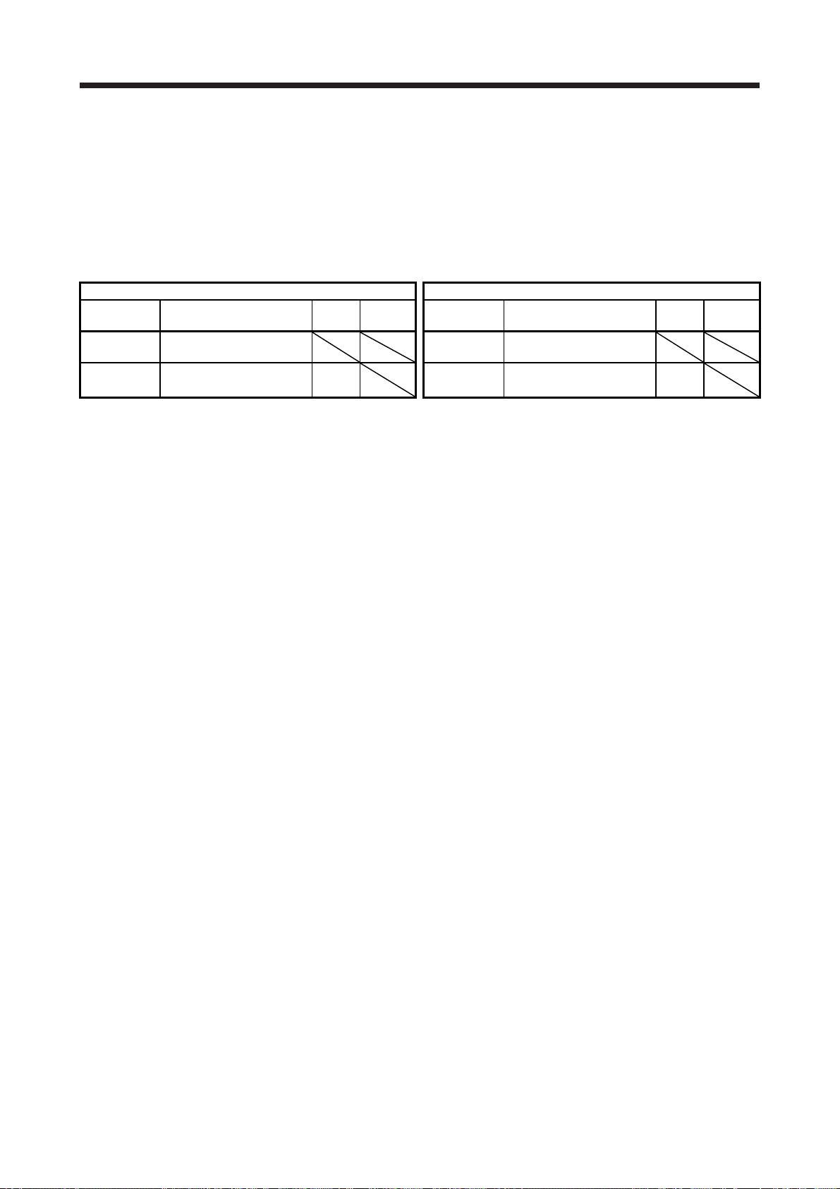
When you keep or use the equipment, please fulfill the following environment.
Item Environment
Ambient
temperature
Storage -20 °C to 65 °C (non-freezing)
Ambient
humidity
Storage
Ambience Indoors (no direct sunlight), free from corrosive gas, flammable gas, oil mist, dust, and dirt
Altitude 2000 m or less above sea level (Contact your local sales office for the altitude for options.)
Vibration resistance 5.9 m/s2, at 10 Hz to 55 Hz (directions of X, Y and Z axes)
When the product has been stored for an extended period of time, contact your local sales office.
When handling the servo amplifier, be careful about the edged parts such as corners of the servo
amplifier.
The servo amplifier must be installed in a metal cabinet.
When fumigants that contain halogen materials such as fluorine, chlorine, bromine, and iodine are used
for disinfecting and protecting wooden packaging from insects, they cause malfunction when entering our
products. Please take necessary precautions to ensure that remaining materials from fumigant do not
enter our products, or treat packaging with methods other than fumigation (heat method). Additionally,
disinfect and protect wood from insects before packing products.
To prevent a fire or injury from occurring in case of an earthquake or other natural disasters, securely
install, mount, and wire the servo motor in accordance with the Instruction Manual.
Operation 0 °C to 55 °C (non-freezing)
Operation
5 %RH to 90 %RH (non-condensing)
A - 3

r
(2) Wiring
CAUTION
Before removing the CNP1 connector of MR-JE-40C to MR-JE-100C, disconnect the lead wires of the
regenerative resistor from the CNP1 connector.
Wire the equipment correctly and securely. Otherwise, the servo motor may operate unexpectedly.
Make sure to connect the cables and connectors by using the fixing screws and the locking mechanism.
Otherwise, the cables and connectors may be disconnected during operation.
Do not install a power capacitor, surge killer, or radio noise filter (optional FR-BIF) on the servo amplifier
output side.
To avoid a malfunction, connect the wires to the correct phase terminals (U/V/W) of the servo amplifier
and servo motor.
Connect the servo amplifier power output (U/V/W) to the servo motor power input (U/V/W) directly. Do
not let a magnetic contactor, etc. intervene. Otherwise, it may cause a malfunction.
Servo amplifier
U
V
W
Servo motor
U
V
W
Servo motorServo amplifier
U
M
V
W
U
V
W
M
The connection diagrams in this instruction manual are shown for sink interfaces, unless stated
otherwise.
The surge absorbing diode installed to the DC relay for control output should be fitted in the specified
direction. Otherwise, the emergency stop and other protective circuits may not operate.
Servo amplifier
DOCOM
Control output
signal
For sink output interface
24 V DC
RA
Servo amplifie
DOCOM
Control output
signal
For source output interface
24 V DC
RA
When the cable is not tightened enough to the terminal block, the cable or terminal block may generate
heat because of the poor contact. Be sure to tighten the cable with specified torque.
Connecting a servo motor of the wrong axis to U, V, W, or CN2 of the servo amplifier may cause a
malfunction.
Configure a circuit to turn off EM2 or EM1 when the power supply is turned off to prevent an unexpected
restart of the servo amplifier.
To prevent malfunction, avoid bundling power lines (input/output) and signal cables together or running
them in parallel to each other. Separate the power lines from the signal cables.
(3) Test run and adjustment
CAUTION
When executing a test run, follow the notice and procedures in this instruction manual. Otherwise, it may
cause a malfunction, damage to the machine, or injury.
Before operation, check the parameter settings. Improper settings may cause some machines to operate
unexpectedly.
A - 4
CAUTION
Never adjust or change the parameter values extremely as it will make operation unstable.
Do not get close to moving parts during the servo-on status.
(4) Usage
CAUTION
When it is assumed that a hazardous condition may occur due to a power failure or product malfunction,
use a servo motor with an external brake to prevent the condition.
For equipment in which the moving part of the machine may collide against the load side, install a limit
switch or stopper to the end of the moving part. The machine may be damaged due to a collision.
Do not disassemble, repair, or modify the product. Otherwise, an electric shock, fire, injury, etc. may
occur. Disassembled, repaired, and/or modified products are not covered under warranty.
Before resetting an alarm, make sure that the run signal of the servo amplifier is off in order to prevent a
sudden restart. Otherwise, it may cause an accident.
Use a noise filter, etc. to minimize the influence of electromagnetic interference. Electromagnetic
interference may be given to the electronic equipment used near the servo amplifier.
Burning or breaking a servo amplifier may cause a toxic gas. Do not burn or break it.
Use the servo amplifier with the specified servo motor.
Correctly wire options and peripheral equipment, etc. in the correct combination. Otherwise, an electric
shock, fire, injury, etc. may occur.
The electromagnetic brake on the servo motor is designed to hold the motor shaft and should not be
used for ordinary braking.
For such reasons as incorrect wiring, service life, and mechanical structure (e.g. where a ball screw and
the servo motor are coupled via a timing belt), the electromagnetic brake may not hold the motor shaft.
To ensure safety, install a stopper on the machine side.
If the dynamic brake is activated at power-off, alarm occurrence, etc., do not rotate the servo motor by an
external force. Otherwise, it may cause a fire.
(5) Corrective actions
CAUTION
Ensure safety by confirming the power off, etc. before performing corrective actions. Otherwise, it may
cause an accident.
If it is assumed that a power failure, machine stoppage, or product malfunction may result in a hazardous
situation, use a servo motor with an electromagnetic brake or provide an external brake system for
holding purpose to prevent such hazard.
When any alarm has occurred, eliminate its cause, ensure safety, and deactivate the alarm before
restarting operation.
If the molded-case circuit breaker or fuse is activated, be sure to remove the cause and secure safety
before switching the power on. If necessary, replace the servo amplifier and recheck the wiring.
Otherwise, it may cause smoke, fire, or an electric shock.
Provide an adequate protection to prevent unexpected restart after an instantaneous power failure.
A - 5
CAUTION
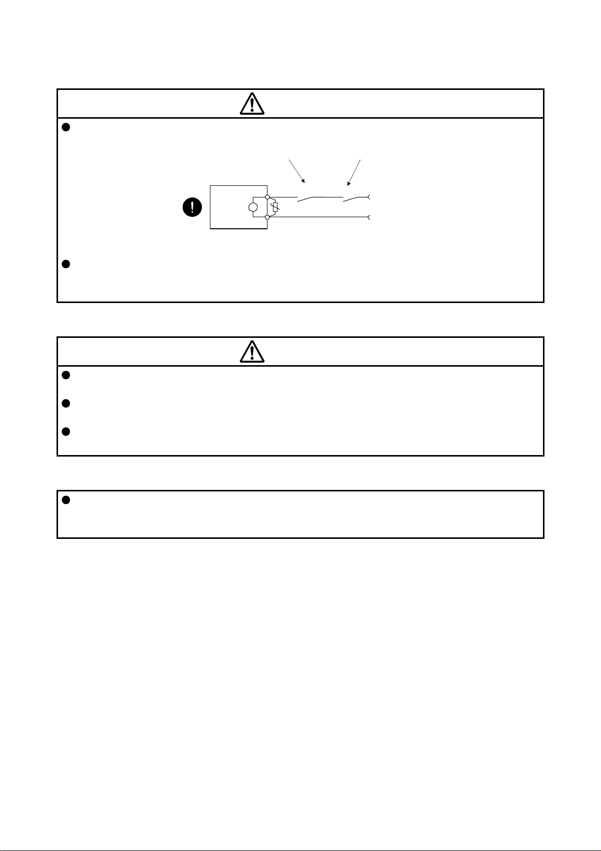
Configure an electromagnetic brake circuit which is interlocked with an external emergency stop switch.
Contacts must be opened when ALM
(Malfunction) or MBR (Electromagnetic
brake interlock) turns off.
Contacts must be opened
with the emergency stop switch.
Servo motor
B
Electromagnetic brake
To prevent an electric shock, injury, or fire from occurring after an earthquake or other natural disasters,
ensure safety by checking conditions, such as the installation, mounting, wiring, and equipment before
switching the power on.
RA
U
24 V DC
(6) Maintenance, inspection and parts replacement
CAUTION
Make sure that the emergency stop circuit operates properly such that an operation can be stopped
immediately and a power is shut off by the emergency stop switch.
It is recommended that the servo amplifier be replaced every 10 years when it is used in general
environment.
When using a servo amplifier whose power has not been turned on for a long time, contact your local
sales office.
(7) General instruction
To illustrate details, the equipment in the diagrams of this Instruction Manual may have been drawn
without covers and safety guards. When the equipment is operated, the covers and safety guards must
be installed as specified. Operation must be performed in accordance with this Instruction Manual.
A - 6

DISPOSAL OF WASTE
Please dispose a servo amplifier, battery (primary battery) and other options according to your local laws and
regulations.
EEP-ROM life
The number of write times to the EEP-ROM, which stores parameter settings, etc., is limited to 100,000. If
the total number of the following operations exceeds 100,000, the servo amplifier may malfunction when the
EEP-ROM reaches the end of its useful life.
Write to the EEP-ROM due to parameter setting changes
Write to the EEP-ROM due to device changes
Compliance with global standards
For the compliance with global standards, refer to app. 3 of "MR-JE-_C Servo Amplifier Instruction Manual".
«About the manual»
You must have this Instruction Manual and the following manuals to use this servo. Ensure to prepare
them to use the servo safely.
Relevant manuals
Manual name Manual No.
MELSERVO MR-JE-_C Servo Amplifier Instruction Manual SH(NA)030257ENG
MELSERVO-JE Servo Amplifier Instruction Manual (Troubleshooting) SH(NA)030166ENG
MELSERVO MR-JE-_C Servo Amplifier Instruction Manual (Profile Mode) SH(NA)030254ENG
MELSERVO HG-KN/HG-SN Servo Motor Instruction Manual SH(NA)030135ENG
MELSERVO EMC Installation Guidelines IB(NA)67310ENG
«Cables used for wiring»
Wires mentioned in this Instruction Manual are selected based on the ambient temperature of 40 °C.
«U.S. customary units»
U.S. customary units are not shown in this manual. Convert the values if necessary according to the
following table.
Quantity SI (metric) unit U.S. customary unit
Mass 1 [kg] 2.2046 [lb]
Length 1 [mm] 0.03937 [inch]
Torque 1 [N•m] 141.6 [oz•inch]
Moment of inertia 1 [(× 10-4 kg•m2)] 5.4675 [oz•inch2]
Load (thrust load/axial load) 1 [N] 0.2248 [lbf]
Temperature N [°C] × 9/5 + 32 N [°F]
A - 7

MEMO
A - 8

CONTENTS
1. FUNCTIONS AND CONFIGURATION 1- 1 to 1- 6
1.1 Outline of CC-Link IE Field Network Basic ....................................................................................... 1- 1
1.1.1 Features ..................................................................................................................................... 1- 1
1.2 Function List ...................................................................................................................................... 1- 2
1.3 Communication specifications .......................................................................................................... 1- 5
1.3.1 Communication specifications of CC-Link IE Field Network Basic .......................................... 1- 5
1.3.2 SLMP communication specifications ......................................................................................... 1- 6
2. CC-Link IE FIELD NETWORK BASIC PROTOCOL 2- 1 to 2- 4
2.1 Summary ........................................................................................................................................... 2- 1
2.2 Message format ................................................................................................................................ 2- 1
2.3 Link device ........................................................................................................................................ 2- 2
2.4 Mapping data details of link device ................................................................................................... 2- 3
3. SLMP 3- 1 to 3- 8
3.1 Summary ........................................................................................................................................... 3- 1
3.2 Message format ................................................................................................................................ 3- 2
3.3 Command ......................................................................................................................................... 3- 4
3.4 CiA 402 read/write command ........................................................................................................... 3- 4
3.4.1 SDO Upload (CiA 402 object read) ............................................................................................ 3- 5
3.4.2 SDO Download (CiA 402 object write) ....................................................................................... 3- 5
3.4.3 SDO Object SubID Block Upload (CiA 402 object sub ID continuous read) ............................. 3- 6
3.4.4 SDO Object SubID Block Download (CiA 402 object sub ID continuous write) ........................ 3- 7
3.5 Error codes ....................................................................................................................................... 3- 8
4. STARTUP 4- 1 to 4- 2
4.1 CC-Link IE Field Network Basic initial communication setting ......................................................... 4- 1
4.2 IP address setting ............................................................................................................................. 4- 2
5. PARAMETERS 5- 1 to 5- 8
5.1 List of communication-related parameters ....................................................................................... 5- 1
5.2 Detailed list of communication-related parameters .......................................................................... 5- 3
6. MANUFACTURER FUNCTIONS 6- 1 to 6- 6
6.1 Stroke end ......................................................................................................................................... 6- 1
6.2 One-touch tuning .............................................................................................................................. 6- 2
6.3 Machine diagnosis function .............................................................................................................. 6- 4
6.4 Servo amplifier life diagnosis function .............................................................................................. 6- 5
7. OBJECT LIBRARY 7- 1 to 7-44
7.1 Object library list ............................................................................................................................... 7- 1
7.2 Object library details (objects in the 1000s) ..................................................................................... 7-17
7.2.1 Writing command to EEP-ROM (1010h) ................................................................................... 7-17
1

7.2.2 Restore default EEP-ROM parameters (1011h) ....................................................................... 7-18
7.2.3 Response message mapping (1A00h) ..................................................................................... 7-19
7.3 Object library details (objects in the 2000s) ..................................................................................... 7-20
7.3.1 External input pin status (2C10h) .............................................................................................. 7-20
7.3.2 External output pin status (2C11h) ........................................................................................... 7-21
7.3.3 Input device status (2C12h) ...................................................................................................... 7-21
7.3.4 Control input (2D01h to 2D0Ah) ................................................................................................ 7-23
7.3.5 Control output (2D11h to 2D1Ah) ............................................................................................. 7-28
7.4 Object library details (objects in the 6000s) ..................................................................................... 7-34
7.4.1 Control status (6041h) ............................................................................................................... 7-34
7.4.2 Quick stop option code (605Ah) ................................................................................................ 7-35
7.4.3 Halt option code (605Dh) .......................................................................................................... 7-36
7.4.4 Control mode display (6061h) ................................................................................................... 7-37
7.4.5 Software limit (607Dh) ............................................................................................................... 7-37
7.4.6 Polarity (607Eh) ........................................................................................................................ 7-38
7.4.7 Degree (60F2h) ......................................................................................................................... 7-38
7.4.8 Touch probe (60B8h to 60BBh) ................................................................................................ 7-40
7.4.9 Touch probe function setting (60B8h) ....................................................................................... 7-41
7.4.10 Touch probe function status (60B9h) ...................................................................................... 7-42
7.4.11 Rising edge position of touch probe (60BAh) ......................................................................... 7-42
7.4.12 Falling edge position of touch probe (60BBh) ......................................................................... 7-42
7.4.13 Supported control mode (6502h) ............................................................................................ 7-43
2

1. FUNCTIONS AND CONFIGURATION
1. FUNCTIONS AND CONFIGURATION
1.1 Outline of CC-Link IE Field Network Basic
CC-Link IE Field Network Basic is a standard Ethernet-based protocol used to perform cyclic communication
by the installed software without using a dedicated ASIC. You can establish a highly flexible system because
CC-Link IE Field Network Basic can be used together with TCP/IP communications.
Up to 64 axes of servo amplifiers (up to 16 axes of servo amplifiers per group) can be monitored by the
controller.
In the profile position mode, positioning operation can be performed based on the position data (target
position) given via the controller.
1.1.1 Features
(1) High-speed communication
High-speed communication can be established by cyclic transmission of not only bit data but also word
data.
The maximum communication speed is 100 Mbps.
(2) General-purpose Ethernet supported
Dedicated control wiring is unnecessary, and Ethernet network can be integrated.
1 - 1

1. FUNCTIONS AND CONFIGURATION
1.2 Function List
The following table lists the functions of this servo. For details of the functions, refer to each section
indicated in the detailed explanation field.
Function Description
Position control mode (P)
(pulse train input)
Speed control mode (S)
(Analog input/DI input)
Torque control mode (T)
(Analog input)
Position/speed control
switching mode (P/S)
Speed/torque control switch
mode (S/T)
Torque/position control switch
mode (T/P)
Profile position mode (pp) The servo amplifier operates in the profile position mode.
Profile velocity mode (pv) The servo amplifier operates in the profile velocity mode.
Profile torque mode (tq) The servo amplifier operates in the profile torque mode.
Homing mode (hm) The servo amplifier operates in the home position return mode.
Absolute position detection
system
Model adaptive control
Touch probe function
Command pulse selection Command pulse train form can be selected from among three different types.
High-resolution encoder
Gain switching function
Advanced vibration
suppression control II
Machine resonance
suppression filter
Shaft resonance suppression
filter
Adaptive filter II
Low-pass filter
This servo amplifier is used as a position control servo.
This servo amplifier is used as a speed control servo.
This servo amplifier is used as a torque control servo.
Using an input device, control can be switched between position control and speed
control.
Using an input device, control can be switched between speed control and torque
control.
Using an input device, control can be switched between torque control and position
control.
Setting a home position once makes home position return unnecessary at every
power-on.
This function achieves a high response and stable control following the ideal model.
The two-degrees-of-freedom model adaptive control enables you to set a response
to the command and a response to the disturbance separately.
Additionally, this function can be disabled. To disable this function, refer to section
7.4 of "MR-JE-C_ Servo Amplifier Instruction Manual".
The touch probe function is available only in the profile mode. When the touch probe
1 signal turns on, the current position latch function will latch the current position.
The latched data can be read with communication commands.
High-resolution encoder of 131072 pulses/rev is used for the encoder of the servo
motor compatible with the MELSERVO-JE series.
You can switch gains during rotation and during stop, and can use an
input device to switch gains during operation.
This function suppresses vibration or residual vibration at an arm end.
This filter function (notch filter) decreases the gain of the specific frequency to
suppress the resonance of the mechanical system.
When a load is mounted to the servo motor shaft, resonance by shaft torsion during
driving may generate a mechanical vibration of high frequency. The shaft resonance
suppression filter suppresses the vibration.
The servo amplifier detects mechanical resonance and sets filter characteristics
automatically to suppress mechanical vibration.
Suppresses high-frequency resonance which occurs as the servo system response is
increased.
explanation
"MR-JE-_C
Servo Amplifier
Instruction
Manual"
"MR-JE-_C
Servo Amplifier
Instruction
Manual (Profile
Mode)"
"MR-JE-_C
Servo Amplifier
Instruction
Manual" /
"MR-JE-_C
Servo Amplifier
Instruction
Manual (Profile
Mode)"
Section 7.4.8
"MR-JE-_C
Servo Amplifier
Instruction
Manual"
"MR-JE-_C
Servo Amplifier
Instruction
Manual"
Detailed
1 - 2

1. FUNCTIONS AND CONFIGURATION
Function Description
Analyzes the frequency characteristic of the mechanical system by simply
Machine analyzer function
Robust filter
Slight vibration suppression
control
Electronic gear
S-pattern
acceleration/deceleration time
constant
Auto tuning
Regenerative option
Alarm history clear Clears alarm histories.
Input signal selection (device
settings)
Output signal selection
(device settings)
Output signal (DO) forced
output
Torque limit Limits the servo motor torque.
Speed limit Servo motor speed can be limited to any value.
Automatic VC offset
Alarm code output If an alarm has occurred, the corresponding alarm number is outputted in 3-bit code.
Test operation mode
MR Configurator2
One-touch tuning
Tough drive function
Drive recorder function
connecting an MR Configurator2 installed personal computer and the servo
amplifier.
MR Configurator2 is necessary for this function.
Improves a disturbance response when a response performance cannot be
increased because of a large load to motor inertia ratio, such as a roll feed axis.
Suppresses vibration of ±1 pulse generated at a servo motor stop.
The position control is performed based on a value obtained by multiplying the
position command from the controller by the set electronic gear ratio.
When the position control mode is used, the input pulses can be multiplied by 1/10
to 4000.
When the profile position mode is used, the position commands can be multiplied by
1/27649 to 8484.
Enables smooth acceleration and deceleration.
Set S-pattern acceleration/deceleration time constants with [Pr. PC03].
As compared with linear acceleration/deceleration, the acceleration/deceleration
time will be longer for the S-pattern acceleration/deceleration time constants
regardless of command speed.
Automatically adjusts the gain to optimum value if load applied to the servo motor
shaft varies.
Use a regenerative option when the built-in regenerative resistor of the servo
amplifier does not have sufficient regenerative capacity for a large regenerative
power generated.
ST1 (Forward rotation start), ST2 (Reverse rotation start), and SON (Servo-on) and
other input device can be assigned to certain pins of the CN3 connector.
The output devices including MBR (Electromagnetic brake interlock) can be
assigned to certain pins of the CN3 connector.
Turns on/off the output signals forcibly independently of the servo status.
Use this function for checking output signal wiring, etc.
Voltage is automatically offset to stop the servo motor if it does not come to a stop
when VC (Analog speed command) is 0 V.
MR Configurator2 is necessary for this function.
Jog operation, positioning operation, motor-less operation, DO forced output, and
program operation
MR Configurator2 is necessary for this function.
Using a personal computer, you can perform the parameter setting, test operation,
monitoring, and others.
Gain adjustment is performed just by one click on MR Configurator2.
This function is available with MR Configurator2 or via a network.
This function makes the equipment continue operating even under the condition that
an alarm occurs.
The tough drive function includes two types: the vibration tough drive and the
instantaneous power failure tough drive.
This function continuously monitors the servo status and records the status transition
before and after an alarm for a fixed period of time. You can check the recorded data
by clicking the Waveform-Display button in the drive recorder window of MR
Configurator2.
However, the drive recorder is not available when:
1. You are using the graph function of MR Configurator2.
2. You are using the machine analyzer function.
3. [Pr. PF21] is set to "-1".
Detailed
explanation
"MR-JE-_C
Servo Amplifier
Instruction
Manual"
"MR-JE-_C
Servo Amplifier
Instruction
Manual"
Section 6.2
"MR-JE-_C
Servo Amplifier
Instruction
Manual"
"MR-JE-_C
Servo Amplifier
Instruction
Manual"
1 - 3

1. FUNCTIONS AND CONFIGURATION
Function Description
You can check the cumulative energization time and the number of on/off times of the
Servo amplifier life diagnosis
function
Power monitoring function
Machine diagnosis function
Modbus/TCP
CC-Link IE Field Network
Basic
SLMP
IP address filtering function
Operation specification IP
address function
Lost motion compensation
function
Limit switch
Software limit
inrush relay. This function gives an indication of the replacement time for parts of the
servo amplifier including a capacitor and a relay before they malfunction.
This function is available with MR Configurator2 or via a network. (Refer to section
6.4.)
This function calculates the power running energy and the regenerative power from
the data in the servo amplifier such as speed and current. Power consumption and
others are displayed on MR Configurator2.
From the data in the servo amplifier, this function estimates the friction and
vibrational component of the drive system in the equipment and recognizes an error
in the machine parts, including a ball screw and bearing.
This function is available with MR Configurator2 or via a network. (Refer to section
6.3.)
The Modbus/TCP uses dedicated message frames for the Ethernet communication
between a client (master) and servers (slaves). The dedicated message frames have
functions for reading and writing data, you can set the parameters of servo amplifiers
and monitor it by using this function. In the profile mode, driving the servo motor is
also possible. This function is used with servo amplifiers with software version A3 or
later.
CC-Link IE Field Network Basic enables fixed cycle communication between the
master and slave stations using a general-purpose Ethernet connector. The
parameters of servo amplifiers can be set (read/written) and monitored. In the profile
mode, driving the servo motor is also possible.
SLMP (SeamLess Message Protocol) is a protocol to access SLMP-compatible
devices from external devices (such as a personal computer and an HMI) or
programmable controller CPU via Ethernet. The parameters of servo amplifiers can
be set (read/written) and monitored. In the profile mode, driving the servo motor is
also possible.
Register the range of IP addresses in advance to limit the network devices allowed
to be connected to the servo amplifier.
In Ethernet communication (CC-Link IE Field Network Basic, SLMP, or
Modbus/TCP), to limit the network devices to which the operation right is given, set
the range of the device IP addresses.
Monitoring/parameter reading can be performed with the network devices having no
operation right.
This function improves the response delay generated when the machine moving
direction is reversed.
Limits travel intervals using LSP (Forward rotation stroke end) and LSN (Reverse
rotation stroke end).
Limits travel intervals by address using parameters.
Enables the same function with the limit switch by setting parameters.
Detailed
explanation
"MELSERVO
MR-JE-_C
Servo Amplifier
Instruction
Manual
(Modbus/TCP)"
Chapter 2
Chapter 3
Chapter 5
"MR-JE-_C
Servo Amplifier
Instruction
Manual"
Section 7.4.5
1 - 4

1. FUNCTIONS AND CONFIGURATION
1.3 Communication specifications
1.3.1 Communication specifications of CC-Link IE Field Network Basic
Function Description
Communication protocol UDP
Port No.
Cyclic data 32 points (64 bytes)
IP address
Subnet mask Default value: 255.255.255.0
Message format Refer to chapter 2.
Physical layer 1000BASE-T
Communication connector RJ45, 1 port (CN1)
Communication cable CAT5e, shielded twisted pair (4 pair) straight cable
Network topology Star
Variable communication
speed
Transmission speed between
stations
Number of nodes
Standard response time
(Note 1)
(Link scan time/timeout time
(Note 2, 3))
Note 1. Standard response time refers to the time from when the servo amplifier receives a command from the master station until
when it returns a response to the master station.
2. Calculate the link scan time as follows. Also, use the standard response time for Ns.
MELSEC iQ-R/MELSEC-Q/L: Ls = Ns + Nm
MELSEC iQ-F: Ls = SM + {(Ns + Nm)/SM}
Ls: Link scan time, Ns: Response time of slave station, Nm: Request time of master station, SM: Sequence scan time
3. Check the current link scan time (when all the slave stations are in a normal state) using the CC-Link IE Field Network Basic
diagnosis function. Then, set the timeout time approximately 5 times the link scan time (example: 50 ms when the current link
scan time is 10 ms).
No. 61450 (cyclic data)
No. 61451 (NodeSearch and IPAddressSet dedicated for CC-Link IE Field Network Basic only)
IPv4 range: 0.0.0.1 to 223.255.255.254
Use the same network address for both the master and slave stations.
Default value: 192.168.3.0
100 Mbps
Max. 100 m
Max. 64 stations (max. number of connections per group: 16 stations)
Number of usable stations: 1 station per MR-JE-_C servo amplifier
10 ms
1 - 5

1. FUNCTIONS AND CONFIGURATION
1.3.2 SLMP communication specifications
Function Description
Communication protocol UDP/TCP (Note)
iQSS No. 45237 (NodeSearch and IPAddressSet only)
Port No.
IP address
Subnet mask Default value: 255.255.255.0
Message format Refer to chapter 3.
Physical layer 1000BASE-T
Communication connector RJ45, 1 port (CN1)
Communication cable CAT5e, shielded twisted pair (4 pair) straight cable
Network topology Star
Variable communication
speed
Transmission speed between
stations
Maximum number
of connections
Note. TCP is supported by servo amplifiers with software version A3 or later.
UDP No. 5010
TCP
(Note)
UDP No limit
TCP
(Note)
No. 5012
IPv4 range: 0.0.0.0 to 255.255.255.255
Use the same network address for both the master and slave stations.
Default value: 192.168.3.0
100 Mbps
Max. 100 m
1
1 - 6

2. CC-Link IE FIELD NETWORK BASIC PROTOCOL
2. CC-Link IE FIELD NETWORK BASIC PROTOCOL
2.1 Summary
In CC-Link IE Field Network Basic, a command that a master station (controller) sends to slave stations
(servo amplifiers) is called a request message, and a command that the slave stations (servo amplifiers)
send back to the master station (controller) is called a response message.
The master station (controller) sends the request message using the directed broadcast to all slave stations
(servo amplifiers). When the servo amplifier receives the request message, it acquires data for own station
and returns the response message to the master station (controller) using the unicast after the servo
amplifier response time. The servo amplifier response time differs depending on the command to send.
Use link devices (RWr, RWw, RX, and RY) for data communications. Sending and receiving the request
message and response message at a constant cycle allow the master station (controller) to perform link
refresh.
The servo amplifier reads the received data as an object library to drive a servo motor and return monitor
data.
Constant cycle
Request message (directed broadcast)
Master station
(controller)
Response message (unicast)
Slave station
(servo amplifier)
2.2 Message format
The following shows the request message format to be used when the master station (controller) sends a
message, and the response message format to be used when the slave stations (servo amplifiers) return a
message.
Messages are sent by using UDP/IP.
(1) Request message format
Ethernet
header
IP
header
UDP
header
CCIEF
Basic
header
Command,
etc.
Link device (for 16 stations)
(RY, RWw)
(2) Response message format
Ethernet
header
IP
header
UDP
header
CCIEF
Basic
header
Slave
station
notification
information
Link device
(RX, RWr)
2 - 1
2. CC-Link IE FIELD NETWORK BASIC PROTOCOL
2.3 Link device
In cyclic communication, communication data of the request message and response message is read as
object data (RWwn, RWrn, RYn, RXn) of the servo amplifier. Table 2.1 and 2.2 list initial settings.
The setting of the response message can be changed. When changing it from the initial setting, refer to
section 7.2.3.
Table 2.1 RYn/RXn mapping (supporting the position/speed/torque control mode, profile mode, and home
position return mode)
(Note)
Device No.
RYn0 to RY
(n + 3) E
RY (n + 3) F
Note. "n" depends on the station No. setting.
Master station → Servo amplifier (RYn) Servo amplifier → Master station (RXn)
Device Symbol Remark
Not used
Cyclic communication ready
command
CSR
(Note)
Device No.
RXn0 to RX
(n + 3) E
RX (n + 3) F Cyclic communication ready SSR
Not used
Device Symbol Remark
2 - 2

2. CC-Link IE FIELD NETWORK BASIC PROTOCOL
Table 2.2 RWwn/RWrn mapping (supporting the position/speed/torque control mode, profile mode, and
home position return mode)
Master station → Servo amplifier (RWwn) Servo amplifier → Master station (RWrn)
(Note)
Device No.
RWwn00 6060 Control mode
RWwn01 6040 Control command Controlword RWrn01
RWwn02 2D01 Control input 1 Control DI 1 RWrn02 6041 Control status Statusword
RWwn03 2D02 Control input 2 Control DI 2 RWrn03
RWwn04 2D03 Control input 3 Control DI 3 RWrn04
RWwn05
RWwn06 RWrn06
RWwn07
RWwn08 RWrn08
RWwn09
RWwn0A
RWwn0B 6071
RWwn0C
RWwn0D RWrn0D 2A42 Alarm No. Current alarm 2
RWwn0E
RWwn0F
RWwn10
RWwn11 RWrn10
RWwn12
RWwn13 RWrn12
RWwn14 60E0
RWwn15 60E1
RWwn16 RWrn17
RWwn17 60B8
RWwn18 60F2
RWwn19 2D05 Control input 5 Control DI 5 RWrn1C
RWwn1A RWrn1D
RWwn1B RWrn1E
RWwn1C RWrn1F
RWwn1D
RWwn1E
RWwn1F
Index Device
Modes of
operation
607A
60FF
2D20 Speed limit value (tq) Velocity limit value RWrn09 6077 Current torque
6081
6083
6084
6087
Position command
(pp)
Speed command
(pv)
Torque command
(tq)
Command speed
(pp)
Acceleration time
constant (pp, pv)
Deceleration time
constant (pp, pv)
Amount of torque
command change
(per second) (tq)
Torque limit value
(forward)
Torque limit value
(reverse)
Touch probe
function setting
Positioning
operation setting
Target position
Target velocity
Target torque
Profile velocity
Profile acceleration RWrn0E 60B9
Profile deceleration
Torque slope
Positive torque
limit value
Negative torque
limit value
Touch probe
function
Positioning option
code
Note. "n" depends on the station No. setting.
2.4 Mapping data details of link device
(Note)
Device No.
RWrn00 6061
RWrn05
RWrn07
RWrn0A 2D11 Control output 1 Status DO 1
RWrn0B 2D12 Control output 2 Status DO 2
RWrn0C 2D13 Control output 3 Status DO 3
RWrn0F
RWrn11
RWrn13
RWrn14
RWrn15
RWrn16
RWrn18
RWrn19
RWrn1A
RWrn1B
Index Device
Control mode
display
6064
606C Current speed
60F4 Droop pulses
60BA
60BB
2C12 Input device status 1
Current position
(command unit)
Touch probe
function status
Touch probe 1
Position latched at
the rising edge
Touch probe 1
Position latched at
the falling edge
Modes of
operation display
Position actual
value
Velocity actual
value
Following error
actual value
Torque actual
value
Touch probe status
Touch probe pos1
pos value
Touch probe pos1
neg value
External Input
signal display1
Refer to chapter 7.
2 - 3

2. CC-Link IE FIELD NETWORK BASIC PROTOCOL
MEMO
2 - 4

3. SLMP
3. SLMP
3.1 Summary
POINT
SLMP (UDP) is supported by servo amplifiers with software version A0 or later.
SLMP (TCP) is supported by servo amplifiers with software version A3 or later.
In SLMP (TCP), if connection with a client disconnects during establishment, the
connection may not close and this may cause reconnection failure. In case you
cannot reconnect, cycle the power of the servo amplifier.
SLMP (SeamLess Message Protocol) is a common protocol which allows applications to communicate
seamlessly regardless of different types of networks and network layers. SLMP communications can be
performed for the connection with external devices, such as a programmable controller, a personal
computer, and HMI, that can send and receive messages by using SLMP control procedures. The MR-JE_C servo amplifier is compatible only with the binary code. It is not compatible with the ASCII code.
For the compatibility of SLMP with external devices, refer to manuals for external devices.
In SLMP, a command that a master station (external device) sends to slave stations (servo amplifiers) is
called a request message, and a command that the slave stations (servo amplifiers) send back to the master
station (external device) is called a response message.
When the servo amplifier receives the request message, it returns the response message to the external
device after the servo amplifier response time.
The external device cannot send the next request message until it completes receiving the response
message.
Master station (external device)
Slave station (servo amplifier)
Request
message
Response
message
Servo amplifier response time (Note)
Request
message
Response
message
Note. The servo amplifier response time differs depending on the command to send.
3 - 1

3. SLMP
3.2 Message format
The following shows the request message format to be used when the master station (external device)
sends a message, and the response message formats to be used when the slave stations (servo amplifiers)
return a message.
(1) Request message format
SLMP
Ethernet
header
IP
header
UDP
header
Subheader
Request
destination
network No.
Request
destination
station No.
Request
destination
module
I/O No.
(2) Response message format
The response message has two different formats for normal completion and abnormal completion.
(a) At normal completion
SLMP
Ethernet
header
IP
header
UDP
header
Subheader
Request
destination
network No.
Request
destination
station No.
Request
destination
module
I/O No.
Request
destination
multi-drop
station No.
Request
destination
multi-drop
station No.
Request
data
length
Response
data
length
Monitoring
timer
End code
Request data
Response data
Footer
Footer
(b) At abnormal completion
UDP
Ethernet
header
IP
header
header
SLMP
Subheader
Request
destination
network No.
Request
destination
station No.
Request
destination
module
I/O No.
Request
destination
multi-drop
station No.
Response
data
length
SLMP
End code Command
Network No.
(responding
station)
Station No.
(responding
station)
Request
destination
module
I/O No.
Request
destination
multi-drop
station No.
Error information
Sub
command
Footer
3 - 2

3. SLMP
Item Size Endian Description
Header This header is for TCP/IP and UDP/IP. Add the header on the external device
side before sending a message.
TCP/IP is supported by servo amplifiers with software version A3 or later.
Subheader
(QnA compatible 3E
frame)
Subheader
(QnA compatible 4E
frame)
Request destination
network No.
Request destination
station No.
Request destination unit
I/O No.
Request destination
multi-drop station No.
Request data length 2 bytes Little Specify the data length from the monitoring timer to the request data in
Monitoring timer 2 bytes Little Set the waiting time until the servo amplifier that had received a request
Request data Variable Little Specify the command, sub command, and data that indicate the request
Command 2 bytes Little Refer to section 3.3.
Sub command 2 bytes Little Refer to section 3.3.
Response data length 2 bytes Little The data length from the end code to the response data (at normal
End code 2 bytes Little The command processing result is stored. 0 is stored at normal completion. An
Response data Variable Little The read data and others corresponding to the command are stored at normal
Error information 9 bytes The network No. (responding station) (1 byte), station No. (responding station)
Footer This footer is for TCP/IP and UDP/IP. Add the footer on the external device
2 bytes Big At a request: H5000
At a response: HD000
6 bytes Big At a request: H5400 + Serial number + H0000
At a response: HD400 + Serial number + H0000
1 bytes Specify the network No. of the access destination. Specify it in hexadecimal.
Store a value of a request message.
1 bytes Specify the station number of the access destination. Specify it in
hexadecimal.
Store a value of a request message.
2 bytes Little Fixed to H03FF
1 bytes Fixed to H00
hexadecimal.
Example) For 24 bytes: H1800
message from an external device completes read or write processing.
When the servo amplifier cannot return a response message within the
waiting time, the response message will be discarded.
H0000: Waiting until the processing is completed
H0001 to HFFFF (1 to 65535): Waiting time (Unit: 0.25 s)
content.
completion) or error information (at abnormal completion) is stored in
hexadecimal. (Unit: byte)
error code of the servo amplifier is stored at abnormal completion.
Refer to section 3.5 for the error code.
completion.
(1 byte), request destination module I/O No. (2 bytes), and request destination
multi-drop station No. (1 byte) of a station that responds an error are stored at
abnormal completion. Numbers that do not correspond to the content of the
request message may be stored because the information of the station that
responds an error is stored at abnormal completion. The command (2 bytes)
and sub command (2 bytes) in which an error occurs are also stored.
side before sending a message.
TCP/IP is supported by servo amplifiers with software version A3 or later.
3 - 3

3. SLMP
3.3 Command
The following table lists applicable commands.
Name Command
CiA 402 object
read/write
0002h Writes data specified by using the CiA 402 object from the external
0005h Reads data of consecutive sub commands specified by using the CiA
0006h Writes data of consecutive sub commands specified by using the CiA
NodeSearch 0E30h 0000h Detects the server device in the network.
IPAddressSet 0E31h 0000h Sets the IP address of the server device in the network.
Model code read 0101h 0000h Reads the servo amplifier model.
4020h 0001h Reads data specified by using the CiA 402 object from the servo
3.4 CiA 402 read/write command
The MR-JE-_C servo amplifier supports the CiA 402 read/write command.
Service
SDO Upload 4020h 0001h Reads data specified by using the CiA 402 object from the servo
SDO Download 4020h 0002h Writes data specified by using the CiA 402 object from the external
SDO Object SubID Block Upload 4020h 0005h Reads data of consecutive sub commands specified by using the CiA
SDO Object SubID Block
Download
Sub
command
amplifier to the external device.
device to the servo amplifier.
402 object from the servo amplifier to the external device.
402 object from the external device to the servo amplifier.
SLMP
Command
4020h 0006h Writes data of consecutive sub commands specified by using the CiA
Sub
command
amplifier to the external device.
device to the servo amplifier.
402 object from the servo amplifier to the external device.
402 object from the external device to the servo amplifier.
Description
Description
Detailed
explanation
Section
3.4.1
Section
3.4.2
Section
3.4.3
Section
3.4.4
3 - 4

3. SLMP
3.4.1 SDO Upload (CiA 402 object read)
When the slave stations (servo amplifiers) receive the CiA 402 object read request from the master station
(external device), they return a value of the object corresponding to the specified Index or Sub Index.
(1) Request message (command and the following)
Command Sub command Index
L H L H L H - - L H
20h 40h 01h 00h Refer to (3) in this section for details.
(2) Response message
(a) At normal completion (end code and the following)
End code Index
L H L H - - L H L or H (variable)
00h 00h Refer to (3) in this section for details.
Sub
Index
Reserved
(b) At abnormal completion
The response message is the same as that of 3.2 (2) (b).
(3) Item list
Command 2 bytes Little H4020
Sub command 2 bytes Little H0001
Index 2 bytes Little Specify Index of the object. (Refer to chapter 7.)
Sub Index 1 bytes Little Specify Sub Index of the object. (Refer to chapter 7.)
Reserved 1 bytes Fixed to H00
Number of data value 2 bytes Little Read data: Fixed to H00
Read data Variable Little The response data of the object is stored.
Item Size Endian Description
For the response message, the value specified in the request message is
stored.
For the response message, the value specified in the request message is
stored.
3.4.2 SDO Download (CiA 402 object write)
Sub
Index
Number of data
Reserved
value
Number of data
value
Read data
When the slave stations (servo amplifiers) receive the CiA 402 object write request from the master station
(external device), they write a specified value to the object corresponding to the specified Index or Sub
Index.
(1) Request message (command and the following)
Command Sub command Index
L H L H L H - - L H L or H (variable)
20h 40h 02h 00h Refer to (3) in this section for details.
Sub
Index
Reserved
Number of data
value
Write data
(2) Response message
(a) At normal completion (end code and the following)
End code Index
L H L H - - L H
00h 00h Refer to (3) in this section for details.
Sub
Index
Reserved
Number of data
value
3 - 5

3. SLMP
(b) At abnormal completion
The response message is the same as that of 3.2 (2) (b).
(3) Item list
Command 2 bytes Little H4020
Sub command 2 bytes Little H0002
Index 2 bytes Little Specify Index of the object. (Refer to chapter 7.)
Sub Index 1 bytes Little Specify Sub Index of the object. (Refer to chapter 7.)
Reserved 1 bytes Fixed to H00
Number of data value 2 bytes Little Write data: Specify the size in hexadecimal.
Write data Variable Little Specify the write data of the object.
3.4.3 SDO Object SubID Block Upload (CiA 402 object sub ID continuous read)
When the slave stations (servo amplifiers) receive the CiA 402 object sub ID continuous read request from
the master station (external device), they return a value of the object corresponding to the specified Index or
consecutive Sub Index.
(1) Request message (command and the following)
(2) Response message
(3) Item list
Command 2 bytes Little H4020
Sub command 2 bytes Little H0005
Index 2 bytes Little Specify Index of the object. (Refer to chapter 7.)
Sub Index 1 bytes Little Specify Sub Index of the object. (Refer to chapter 7.)
Reserved 1 bytes Fixed to H00
Number of data value 2 bytes Little Read data: Fixed to H00
Read data Variable Little The response data of the object is stored.
Item Size Endian Description
For the response message, the value specified in the request message is
stored.
For the response message, the value specified in the request message is
stored.
Command Sub command Index
L H L H L H - - L H
20h 40h 05h 00h Refer to (3) in this section for details.
Sub
Index
Reserved
Number of data
value
(a) At normal completion (end code and the following)
End code Index
L H L H - - L H L or H (variable)
00h 00h Refer to (3) in this section for details.
Sub
Index
Reserved
Number of data
value
Read data
(b) At abnormal completion
The response message is the same as that of 3.2 (2) (b).
Item Size Endian Description
For the response message, the value specified in the request message is
stored.
For the response message, the value specified in the request message is
stored.
3 - 6

3. SLMP
3.4.4 SDO Object SubID Block Download (CiA 402 object sub ID continuous write)
When the slave stations (servo amplifiers) receive the CiA 402 object sub ID continuous write request from
the master station (external device), they write a specified value to the object corresponding to the specified
Index or consecutive Sub Index.
(1) Request message (command and the following)
Command Sub command Index
L H L H L H - - L H L or H (variable)
20h 40h 06h 00h Refer to (3) in this section for details.
(2) Response message
(a) At normal completion (end code and the following)
End code Index
L H L H - - L H
00h 00h Refer to (3) in this section for details.
Sub
Index
Reserved
(b) At abnormal completion
The response message is the same as that of 3.2 (2) (b).
(3) Item list
Command 2 bytes Little H4020
Sub command 2 bytes Little H0006
Index 2 bytes Little Specify Index of the object. (Refer to chapter 7.)
Sub Index 1 bytes Little Specify Sub Index of the object. (Refer to chapter 7.)
Reserved 1 bytes Fixed to H00
Number of data value 2 bytes Little Write data: Specify the size in hexadecimal.
Write data Variable Little Specify the write data of the object.
Item Size Endian Description
For the response message, the value specified in the request message is
stored.
For the response message, the value specified in the request message is
stored.
Sub
Index
Number of data
Reserved
value
Number of data
value
Write data
3 - 7

3. SLMP
3.5 Error codes
The following table lists error codes that are stored in the end code at abnormal completion in SLMP.
Error code Cause
C059h The sub command is specified incorrectly. Or, a command that is not prescribed is received.
C05Ch The request message is incorrect.
C061h The request data length does not correspond to the number of data points.
CCCAh A non-existent Index is specified.
CCD0h Number of data value differs from the prescribed value.
CCD1h Number of data value is greater than the prescribed value.
CCD2h Number of data value is smaller than the prescribed value.
CCD3h A non-existent Sub Index is specified.
CCC8h The Write only object is read.
CCC9h (1) A value is written to the Read only object.
(2) A value is written to an object which is not the Read only object for all AL states but for the present AL state with
Write disabled.
CCC7h (1) A value is written to the object mapped to a response message.
(2) The following writings are performed when the object mapped to a response message is not allowed to be
changed.
A value other than "0" is written to Sub Index0.
A value is written to the corresponding Sub Index 1 to 32.
CCCBh The object that cannot be mapped to response message is written to the object mapped to a response message.
CCCCh The total size of the object mapped to a response message exceeds 64 bytes.
CCD4h A value outside the parameter range was written.
CCD5h A value that is greater than the parameter range is written.
CCD6h A value that is smaller than the parameter range is written.
CCDAh A value is written to a parameter object outside the writing range set in the Parameter block setting.
3 - 8

4. STARTUP
4. STARTUP
POINT
Setting [Pr. PN02 Communication error detection time] to several milliseconds
may trigger [AL. 86.1] in the following condition. The power of the servo amplifier
is cycled, or an instantaneous power failure occurs during CC-Link IE Field
Network Basic communication.
Setting [Pr. PN10 Ethernet communication time-out selection] to several
milliseconds may trigger [AL. 86.4] in the following condition. The power of the
servo amplifier is cycled, or an instantaneous power failure occurs during SLMP
communication.
This chapter describes the network setting of the MR-JE-_C servo amplifier. Refer to "MR-JE-_C Servo
Amplifier Instruction Manual" and "MR-JE-_C Servo Amplifier Instruction Manual (Profile Mode)" for other
startup settings.
4.1 CC-Link IE Field Network Basic initial communication setting
Start the cyclic communication in the following procedure.
Network setting
IP address setting
Subnet mask setting
Default gateway setting
Slave station (servo amplifier)
Communication start
procedure
Master station (controller)
cyclic communication start
Cyclic communication ready
power cycling
[IP address setting]
The initial value is 192.168.3.0. To change the initial value, set it with any of the following
(1) to (3). (Refer to section 4.2.)
(1) Identification number setting rotary switch (SW1/SW2)
(2) Parameter ([Pr. PN11] to [Pr. PN14])
(3) SLMP communication (IP Address Set command)
[Subnet mask setting]
The initial value is 255.255.255.0. To change the initial value, set it with either of the
following (1) or (2). (Refer to chapter 5.)
(1) Parameter ([Pr. PN15] to [Pr. PN18])
(2) SLMP communication (IP Address Set command)
[Default gateway setting]
The initial value is 192.168.3.1. To change the initial value, set it with either of the
following (1) or (2). (Refer to chapter 5.)
(1) Parameter ([Pr. PN19] to [Pr. PN22])
(2) SLMP communication (IP Address Set command)
[Slave station (servo amplifier) power cycling]
The settings of the IP address, subnet mask, and default gateway are reflected.
[Cyclic communication start]
Start the cyclic communication of the master station (controller).
[Cyclic communication ready]
Set RY (n + 3) F of the master station (controller) to "01h". For the slave stations (servo
amplifiers), start importing the word device (RWw) and set RX (n + 3) F to "01h".
For the master station (controller), check that RX (n + 3) F is "01h" and read the word
device (RWr).
4 - 1

4. STARTUP
4.2 IP address setting
POINT
Use a twisted pair cable with Ethernet Category 5e (1000BASE-T) or higher as
an Ethernet cable. The maximum cable length between nodes is 100 m.
Use a hub with a transmission speed of 100 Mbps or faster when branching the
Ethernet communication using a switching hub.
For the switching hub without the auto-negotiation function, set it to the
transmission speed 100 Mbps and half duplex.
The initial value of the IP address is 192.168.3.0.
The 4th octet can be set to 1 to 255 by using the identification number setting
rotary switch (SW1/SW2).
Cycle the power of the servo amplifier after changing the parameter setting of
the IP address or identification number setting rotary switch (SW1/SW2).
The IP address range of CC-Link IE Field Network Basic is between 0.0.0.0 to
223.255.255.254. Set the IP address within the range.
Set the IP address by using the SLMP command with the identification number setting rotary switch
(SW1/SW2) on the display of the servo amplifier, MR Configurator2, or controller.
When the IP address is changed with the identification number setting rotary switch (SW1/SW2), change it
before powering on the servo amplifier.
The IP address can be changed by specifying a MAC address when the SLMP command (IPAddressSet) is
used. Refer to section 3.3 for details on the command.
The IP address you set can be checked in the system configuration window of MR Configurator 2.
The IP address can be set as follows.
Identification number setting
rotary switch (SW1/SW2)
00h
01h to FFh
IP address
1st octet The setting value of [Pr. PN11] is used.
2nd octet The setting value of [Pr. PN12] is used.
3rd octet The setting value of [Pr. PN13] is used.
4th octet The setting value of [Pr. PN14] is used.
1st octet The setting value of [Pr. PN11] is used.
2nd octet The setting value of [Pr. PN12] is used.
3rd octet The setting value of [Pr. PN13] is used.
4th octet
The setting value of the identification number setting rotary switch
(SW1/SW2) is used.
4 - 2

5. PARAMETERS
5. PARAMETERS
Never make a drastic adjustment or change to the parameter values as doing so
will make the operation unstable.
Do not change the parameter settings as described below. Doing so may cause
an unexpected condition, such as failing to start up the servo amplifier.
Changing the values of the parameters for manufacturer setting
CAUTION
5.1 List of communication-related parameters
Setting a value out of the range
Changing the fixed values in the digits of a parameter
When you write parameters with the controller, make sure that the identification
No. of the servo amplifier is set correctly. Otherwise, the parameter settings of
another identification No. may be written, possibly causing the servo amplifier to
be an unexpected condition.
POINT
To enable a parameter whose symbol is preceded by *, cycle the power after
setting it. However, the time will be longer depending on a setting value of [Pr.
PF25 Instantaneous power failure tough drive - Detection time] when
"instantaneous power failure tough drive selection" is enabled in [Pr. PA20].
The following parameters cannot be used with CC-Link IE Field Network Basic
communication.
[Pr. PN10 Ethernet communication time-out selection]
[Pr. PN23 KeepAlive time]
No. Symbol Name
PN01 For manufacturer setting 0h
PN02 CERT Communication error detection time 1000 ms [ms]
PN03 For manufacturer setting 0000h
PN04 0000h
PN05 0000h
PN06 0000h
PN07 0000h
PN08 0000h
PN09 1
PN10 EIC Ethernet communication time-out selection 0 [s]
PN11 *IPAD1 IP address setting 1 192
PN12 *IPAD2 IP address setting 2 168
PN13 *IPAD3 IP address setting 3 3
PN14 *IPAD4 IP address setting 4 0
PN15 *SNMK1 Subnet mask setting 1 255
PN16 *SNMK2 Subnet mask setting 2 255
PN17 *SNMK3 Subnet mask setting 3 255
PN18 *SNMK4 Subnet mask setting 4 0
PN19 *DGW1 Default gateway setting 1 192
PN20 *DGW2 Default gateway setting 2 168
PN21 *DGW3 Default gateway setting 3 3
PN22 *DGW4 Default gateway setting 4 1
PN23 *KAA KeepAlive time 3600 [s]
Initial
value
Unit
5 - 1

5. PARAMETERS
No. Symbol Name
PN24 *IPAF1 IP address filter 1 0
PN25 *IPAF2 IP address filter 2 0
PN26 *IPAF3 IP address filter 3 0
PN27 *IPAF4 IP address filter 4 0
PN28 *IPFR2 IP address filter 2 range setting 256
PN29 *IPFR3 IP address filter 3 range setting 256
PN30 *IPFR4 IP address filter 4 range setting 256
PN31 *IPOA1 Operation specification IP address 1 0
PN32 *IPOA2 Operation specification IP address 2 0
PN33 *IPOA3 Operation specification IP address 3 0
PN34 *IPOA4 Operation specification IP address 4 0
PN35 *IPOR3 Operation specification IP address 3 range specification 256
PN36 *IPOR4 Operation specification IP address 4 range specification 256
PN37 For manufacturer setting 0000h
PN38 0000h
PN39 0000h
PN40 0000h
PN41 0000h
PN42 0000h
PN43 0000h
PN44 0000h
PN45 0000h
PN46 0000h
PN47 0000h
PN48 0000h
Initial
value
Unit
5 - 2

5. PARAMETERS
5.2 Detailed list of communication-related parameters
POINT
Set a value to each "x" in the "Setting digit" columns.
No./symbol/
name
PN02
CERT
Communica-
tion error
detection time
PN10
*CONN
Ethernet
communication time-out
selection
PN11
*IPAD1
IP address
setting 1
Setting
digit
Set the time until [AL. 86.1 Network communication error 1] is detected.
Setting "0" will disable the detection of [AL. 86.1 Network communication error 1].
Setting range: 0 to 1000
Set the network number of the servo amplifier.
Set the time until [AL. 86.4 Network communication error 4] is detected.
Setting "0" will disable the detection of [AL. 86.4 Network communication error 4].
This parameter is enabled with SLMP.
Setting range: 0 to 60
Set the 1st octet of the IP address in decimal.
Set the IP address assigned by the network administrator.
When SLMP command (IPAdressSet) is received, the setting of the first octet will be
written to this parameter.
Refer to table 5.1 for the relation between the setting value of the identification
number setting rotary switch and the parameter setting value.
Setting range: 0 to 255
Table 5.1 Relation between IP address setting and identification number setting rotary switch
Identification number
setting rotary switch
(SW1/SW2)
2nd octet The setting value of [Pr. PN12] is used.
3rd octet The setting value of [Pr. PN13] is used.
4th octet The setting value of [Pr. PN14] is used.
2nd octet The setting value of [Pr. PN12] is used.
3rd octet The setting value of [Pr. PN13] is used.
PN12
*IPAD2
IP address
setting 2
PN13
*IPAD3
IP address
setting 3
00h
01h to FFh
Set the 2nd octet of the IP address in decimal.
Set the IP address assigned by the network administrator.
When SLMP command (IPAdressSet) is received, the setting of the second octet will
be written to this parameter.
Refer to table 5.1 for the relation between the setting value of the identification
number setting rotary switch and the parameter setting value.
Setting range: 0 to 255
Set the 3rd octet of the IP address in decimal.
Set the IP address assigned by the network administrator.
When SLMP command (IPAdressSet) is received, the setting of the third octet will
be written to this parameter.
Refer to table 5.1 for the relation between the setting value of the identification
number setting rotary switch and the parameter setting value.
Setting range: 0 to 255
1st octet The setting value of [Pr. PN11] is used.
1st octet The setting value of [Pr. PN11] is used.
4th octet
Function
IP address
The setting value of the identification number setting
rotary switch (SW1/SW2) is used.
Initial
value
[unit]
1000
[ms]
0
[s]
192
168
3
5 - 3

5. PARAMETERS
No./symbol/
name
PN14
*IPAD4
IP address
setting 4
PN15
*SNMK1
Subnet mask
setting 1
PN16
*SNMK2
Subnet mask
setting 2
PN17
*SNMK3
Subnet mask
setting 3
PN18
*SNMK4
Subnet mask
setting 4
PN19
*DGW1
Default
gateway
setting 1
PN20
*DGW2
Default
gateway
setting 2
PN21
*DGW3
Default
gateway
setting 3
PN22
*DGW4
Default
gateway
setting 4
Setting
digit
Set the 4th octet of the IP address in decimal.
Set the IP address assigned by the network administrator.
When SLMP command (IPAdressSet) is received, the setting of the fourth octet will
be written to this parameter.
Refer to table 5.1 for the relation between the setting value of the identification
number setting rotary switch and the parameter setting value.
Setting range: 0 to 255
Set the 1st octet of the subnet mask in decimal.
Set the subnet mask assigned by the network administrator.
The subnet mask can also be changed simultaneously by the SLMP command
(IPAdressSet).
Setting range: 0 to 255
Set the 2nd octet of the subnet mask in decimal.
Set the subnet mask assigned by the network administrator.
The subnet mask can also be changed simultaneously by the SLMP command
(IPAdressSet).
Setting range: 0 to 255
Set the 3rd octet of the subnet mask in decimal.
Set the subnet mask assigned by the network administrator.
The subnet mask can also be changed simultaneously by the SLMP command
(IPAdressSet).
Setting range: 0 to 255
Set the 4th octet of the subnet mask in decimal.
Set the subnet mask assigned by the network administrator.
The subnet mask can also be changed simultaneously by the SLMP command
(IPAdressSet).
Setting range: 0 to 255
Set the 1st octet of the default gateway in decimal.
Set the default gateway assigned by the network administrator.
The default gateway can also be changed simultaneously by the SLMP command
(IPAdressSet).
Setting range: 0 to 255
Set the 2nd octet of the default gateway in decimal.
Set the default gateway assigned by the network administrator.
The default gateway can also be changed simultaneously by the SLMP command
(IPAdressSet).
Setting range: 0 to 255
Set the 3rd octet of the default gateway in decimal.
Set the default gateway assigned by the network administrator.
The default gateway can also be changed simultaneously by the SLMP command
(IPAdressSet).
Setting range: 0 to 255
Set the 4th octet of the default gateway in decimal.
Set the default gateway assigned by the network administrator.
The default gateway can also be changed simultaneously by the SLMP command
(IPAdressSet).
Setting range: 0 to 255
Function
Initial
value
[unit]
0
255
255
255
0
192
168
3
1
5 - 4

5. PARAMETERS
No./symbol/
name
PN24
*IPAF1
IP address
filter 1
PN25
*IPAF2
IP address
filter 2
PN26
*IPAF3
IP address
filter 3
PN27
*IPAF4
IP address
filter 4
PN28
*IPAF2
IP address
filter 2 range
specification
PN29
*IPAF3
IP address
filter 3 range
specification
PN30
*IPAF4
IP address
filter 4 range
specification
PN31
*IPOA1
Operation
specification
IP address 1
Setting
digit
Set the 1st octet of the IP address of the network device allowed to be connected in
decimal.
When [Pr. PN24] to [Pr. PN27] are all set to "0", the function is disabled.
Setting range: 0 to 255
Set the 2nd octet of the IP address of the network device allowed to be connected in
decimal.
When [Pr. PN24] to [Pr. PN27] are all set to "0", the function is disabled.
Setting range: 0 to 255
Set the 3rd octet of the IP address of the network device allowed to be connected in
decimal.
When [Pr. PN24] to [Pr. PN27] are all set to "0", the function is disabled.
Setting range: 0 to 255
Set the 4th octet of the IP address of the network device allowed to be connected in
decimal.
When [Pr. PN24] to [Pr. PN27] are all set to "0", the function is disabled.
Setting range: 0 to 255
Set a value for the 2nd octet range of the IP address of the network device allowed
to be connected. The range for the IP address of the network device allowed to be
connected is between [Pr. PN25] and [Pr. PN28].
Set a value in decimal.
Setting "256" will disable the function.
Setting range: 0 to 256
Set a value for the 3rd octet range of the IP address of the network device allowed to
be connected. The range for the IP address of the network device allowed to be
connected is between [Pr. PN26] and [Pr. PN29].
Set a value in decimal.
Setting "256" will disable the function.
Setting range: 0 to 256
Set a value for the 4th octet range of the IP address of the network device allowed to
be connected. The range for the IP address of the network device allowed to be
connected is between [Pr. PN27] and [Pr. PN30].
Set a value in decimal.
Setting "256" will disable the function.
Setting range: 0 to 256
Set the 1st octet of the IP address of the network device allowed to be connected in
decimal.
When [Pr. PN31] to [Pr. PN34] are set to all "0", the function is disabled.
When the function is enabled, the servo amplifier allows the following data 1) to 3) to
be imported only if the IP address of the master station (external device) matches
with the operation specification IP address. If they are mismatched, the data is
discarded.
1) SDO Download (command: 4020h, sub command: 0002h)
2) SDO Object SubID Block Download (command: 4020h, sub command: 0006h)
3) CC-Link IE Field Network Basic request message (RWwn)
Monitoring, parameter setting, and test operation can be executed via Ethernet when
the IP addresses of a personal computer (MR Configurator2) and GOT are within the
range of the operation specification IP address. When out of the range,
communication to the servo amplifier cannot be established.
Setting range: 0 to 255
Function
Initial
value
[unit]
0
0
0
0
256
256
256
0
5 - 5

5. PARAMETERS
No./symbol/
name
PN32
*IPOA2
Operation
specification
IP address 2
PN33
*IPOA3
Operation
specification
IP address 3
PN34
*IPOA4
Operation
specification
IP address 4
PN35
*IPOR3
Operation
specification
IP address 3
range
specification
Setting
digit
Set the 2nd octet of the IP address of the network device allowed to be connected in
decimal.
When [Pr. PN31] to [Pr. PN34] are all set to "0", the function is disabled.
When the function is enabled, the servo amplifier allows the following data 1) to 3) to
be imported only if the IP address of the master station (external device) matches
with the operation specification IP address. If they are mismatched, the data is
discarded.
1) SDO Download (command: 4020h, sub command: 0002h)
2) SDO Object SubID Block Download (command: 4020h, sub command: 0006h)
3) CC-Link IE Field Network Basic request message (RWwn)
Monitoring, parameter setting, and test operation can be executed via Ethernet when
the IP addresses of a personal computer (MR Configurator2) and GOT are within the
range of the operation specification IP address. When out of the range,
communication to the servo amplifier cannot be established.
Setting range: 0 to 255
Set the 3rd octet of the IP address of the network device allowed to be connected in
decimal.
When [Pr. PN31] to [Pr. PN34] are all set to "0", the function is disabled.
When the function is enabled, the servo amplifier allows the following data 1) to 3) to
be imported only if the IP address of the master station (external device) matches
with the operation specification IP address. If they are mismatched, the data is
discarded.
1) SDO Download (command: 4020h, sub command: 0002h)
2) SDO Object SubID Block Download (command: 4020h, sub command: 0006h)
3) CC-Link IE Field Network Basic request message (RWwn)
Monitoring, parameter setting, and test operation can be executed via Ethernet when
the IP addresses of a personal computer (MR Configurator2) and GOT are within the
range of the operation specification IP address. When out of the range,
communication to the servo amplifier cannot be established.
Setting range: 0 to 255
Set the 4th octet of the IP address of the network device allowed to be connected in
decimal.
When [Pr. PN31] to [Pr. PN34] are all set to "0", the function is disabled.
When the function is enabled, the servo amplifier allows the following data 1) to 3) to
be imported only if the IP address of the master station (external device) matches
with the operation specification IP address. If they are mismatched, the data is
discarded.
1) SDO Download (command: 4020h, sub command: 0002h)
2) SDO Object SubID Block Download (command: 4020h, sub command: 0006h)
3) CC-Link IE Field Network Basic request message (RWwn)
Monitoring, parameter setting, and test operation can be executed via Ethernet when
the IP addresses of a personal computer (MR Configurator2) and GOT are within the
range of the operation specification IP address. When out of the range,
communication to the servo amplifier cannot be established.
Setting range: 0 to 255
Set a value for the 3rd octet range of the IP address of the network device allowed to
be connected.
The range for the IP address of the network device allowed to be connected is
between [Pr. PN33] and [Pr. PN35]. Set a value in decimal.
Setting "256" will disable the function.
Setting range: 0 to 256
Function
Initial
value
[unit]
0
0
0
256
5 - 6

5. PARAMETERS
No./symbol/
name
PN36
*IPOA4
Operation
specification
IP address 4
range
specification
Setting
digit
Set a value for the 4th octet range of the IP address of the network device allowed to
be connected.
The range for the IP address of the network device allowed to be connected is
between [Pr. PN34] and [Pr. PN36]. Set a value in decimal.
Setting "256" will disable the function.
Setting range: 0 to 256
Function
Initial
value
[unit]
256
5 - 7

5. PARAMETERS
MEMO
5 - 8

6. MANUFACTURER FUNCTIONS
6. MANUFACTURER FUNCTIONS
6.1 Stroke end
When LSP (Forward rotation stroke end) or LSN (Reverse rotation stroke end) is turned off, a slow stop is
performed by either of the following stop methods.
During rotation at constant speed During deceleration to a stop
No S-pattern acceleration/
deceleration
With S-pattern acceleration/
deceleration
Servo motor speed
0 r/min
LSP
or
LSN
ON
OFF
Perform a return as follows when the stroke end is detected.
Mode Return method
Profile position mode (pp) Input the position command of the direction opposite to the limit to Target position (607Ah).
Profile velocity mode (pv) Input the speed command of the direction opposite to the limit to Target velocity (60FFh).
Operation status
Part of droop
pulses
No S-pattern acceleration/
deceleration
With S-pattern acceleration/
deceleration
Servo motor speed
LSP
or
LSN
0 r/min
ON
OFF
Travels for the droop pulse
portion and stops the servo
motor.
A difference will be
Part of
droop
generated between the
pulses
command position and the
current position.
Perform a home position
return again.
Remark
6 - 1

6. MANUFACTURER FUNCTIONS
6.2 One-touch tuning
Refer to "MR-JE-_C Servo Amplifier Instruction Manual" for one-touch tuning. Using One-touch tuning mode
(2D50h) allows one-touch tuning from the master station (controller).
(1) Related object
Index
2D50h 0 Read/write One-touch tuning mode 1 bytes 0
2D51h 0 Reading One-touch tuning status 1 bytes 0
2D52h 0 Writing One-touch tuning Stop 2 bytes 0
2D53h 0 Writing One-touch tuning Clear 2 bytes 0
2D54h 0 Reading One-touch tuning Error Code 2 bytes 0
Sub-
address
Read/write Name
Data
type
Initial
value
Description
Setting a value of "1" to "3" starts onetouch tuning. After one-touch tuning is
completed, the setting value automatically
changes to "0".
0: During one-touch tuning stop
1: Basic mode
2: High mode
3: Low mode
Regardless of whether one-touch tuning is
properly completed or not, the setting
value changes to 100% at the completion.
Unit: %
Writing "1EA5h" stops one-touch tuning.
Writing a value other than "1EA5h" will
trigger the error code "CCD4h".
The parameter changed in one-touch
tuning can be returned to the value before
the change.
0000h: Restores the initial value.
0001h: Restores the value before one-
touch tuning.
The setting value of the restored
parameter is stored to the EEP-ROM.
The following shows the details of the onetouch tuning error codes.
0000h: Finished normally
C000h: Tuning canceled
C001h: Overshoot exceeded
C002h: Servo-off during tuning
C003h: Control mode error
C004h: Time-out
C005h: Load to motor inertia ratio
misestimated
C00Fh: One-touch tuning disabled
6 - 2

6. MANUFACTURER FUNCTIONS
(2) Procedure of one-touch tuning via a network
Perform one-touch tuning via a network in the following procedure.
Start
Startup of the system
Operation
One-touch tuning execution
One-touch tuning in progress
One-touch tuning completion
Tuning result check
End
Refer to "MR-JE-_C Servo Amplifier Instruction Manual" and "MR-JE-_C
Servo Amplifier Instruction Manual (Profile Mode)" to start the system.
Rotate the servo motor by a controller. (One-touch tuning cannot be
performed if the servo motor is not operating.)
Write a value corresponding to the response mode (High mode, basic mode,
or Low mode) to perform in One-touch tuning mode (2D50h) during servo
motor driving to perform one-touch tuning.
Gains and filters will be adjusted automatically. During one-touch tuning, the
progress can be checked with One-touch tuning status (2D51h).
Check whether one-touch tuning is completed normally with One-touch tuning
Error Code (2D54h). When the one-touch tuning is completed normally, the
parameters will be set automatically. Refer to "MR-JE-_C Servo Amplifier
Instruction Manual" for the parameters that are set automatically.
After a tuning error is returned, take the appropriate action according to "MRJE-_C Servo Amplifier Instruction Manual".
Check the tuning result.
If the tuning result is not satisfactory, you can return the parameter to the
value before the one-touch tuning or the initial value using One-touch tuning
Clear (2D53h).
6 - 3

6. MANUFACTURER FUNCTIONS
2
2
2
2
6.3 Machine diagnosis function
This function estimates the friction and vibrational component of the drive system in the equipment based on
the data in the servo amplifier, and recognizes an error in the machine parts, including a ball screw and
bearing. The information of the machine diagnosis function can be obtained with the following objects.
C20h
Bit 0 to Bit 3
Friction estimation status at forward rotation
Bit 4 to Bit 7
Friction estimation status at reverse rotation
Bit 8 to Bit 11
Vibration estimation status
During estimation
During estimation Estimation completed
During estimation
Estimation completed
Estimation completed
C21h/2C22h
C23h/2C24h
C25h to 2C28h
Index
2C20h 0 Reading Machine diagnostic status 2 bytes Refer to section 7.1.
2C21h 0 Reading
2C22h 0 Reading
2C23h 0 Reading
2C24h 0 Reading
2C25h 0 Reading
2C26h 0 Reading
2C27h 0 Reading
2C28h 0 Reading
Sub-
address
Read/write Name
Static friction torque at
forward rotation
Dynamic friction torque at
forward rotation (at rated
Static friction torque at
reverse rotation
Dynamic friction torque at
reverse rotation (at rated
Oscillation frequency during
motor stop
Vibration level during motor
Oscillation frequency during
motor operating
Vibration level during motor
Undefined value Estimated value
Undefined value Estimated value
Undefined value Estimated value
speed)
speed)
stop
operating
Data
type
2 bytes
2 bytes
2 bytes
2 bytes
2 bytes
2 bytes
2 bytes
2 bytes
Initial
value
Static friction at forward rotation torque is
displayed in increments of 0.1%.
Kinetic friction at forward rotation torque at
the rated speed is displayed in increments
of 0.1%.
Static friction at reverse rotation torque is
displayed in increments of 0.1%.
Kinetic friction at reverse rotation torque at
the rated speed is displayed in increments
of 0.1%.
Vibration frequency at stop/servo-lock
Vibration frequency during stop/servo-lock
is displayed in increments of 1 Hz.
Vibration level at stop/servo-lock
Vibration level during stop/servo-lock is
displayed in increments of 0.1%.
Vibration frequency during operation
Vibration frequency during operation is
displayed in increments of 1 Hz.
Vibration level during operation
Vibration level during operation is
displayed in increments of 0.1%.
Description
6 - 4

6. MANUFACTURER FUNCTIONS
6.4 Servo amplifier life diagnosis function
You can check the cumulative energization time and the number of on/off times of the inrush relay based on
the data in the servo amplifier. This function gives an indication of the replacement time for parts of the servo
amplifier including a capacitor and a relay before they malfunction. The information of the servo amplifier life
diagnosis function can be obtained with the following objects.
Index
2C18h 0 Reading Power ON cumulative time 4 bytes
2C19h 0 Reading Inrush relay ON/OFF number 4 bytes
Sub-
address
Read/write Name
Data
type
Initial
value
Description
The cumulative energization time of the
servo amplifier is returned.
The number of on/off times of the inrush
relay of the servo amplifier is returned.
6 - 5

6. MANUFACTURER FUNCTIONS
MEMO
6 - 6

7. OBJECT LIBRARY
7. OBJECT LIBRARY
Each data such as control parameters, command values, and feedback values is handled as an object
composed of an address, object name, data type, access rule, and other elements. The object data can be
exchanged between the master station (controller) and the slave stations (servo amplifiers). The aggregate
of these objects is called object library.
7.1 Object library list
Sub
Index
Index
1000 0 Supported profile information (Device Type)
The servo drive defined with the CiA 402 profile is
indicated.
1001 0 Alarm information (Error Register)
The error occurrence is returned.
Bit 0: Turns on when an alarm has occurred.
Bit 1 to Bit 7: Unused
1008 0 Servo amplifier model (Manufacturer Device
1009 0 Hardware version (Manufacturer Hardware
100A 0 Servo amplifier software version (Manufacturer
1010 0 Writing command to EEP-ROM (Store
1 Saving all parameters (Save all parameters)
1011 0 Restoring default EEP-ROM parameters (Restore
1 Restoring all default parameters (Restore all
1018 0 Device information (Identity Object)
1 Vendor ID (Vendor ID)
2 Product number (Product Code)
3 Revision number (Revision Number)
4 Serial number (Serial Number)
Name)
The model name of the servo amplifier is
returned.
Version)
The hardware version of the network module is
returned.
Software Version)
The software version of the servo amplifier is
returned.
parameters)
The number of entries is returned.
[Writing]
Writing "save" (= 65766173h) saves all the objects
which can be stored in the EEP-ROM.
[Reading]
Bit 0: 0: The parameter cannot be saved with the
1: The parameter can be saved with the
Bit 1: 0: The parameter is not automatically saved.
default parameters)
The number of entries is returned.
default parameters)
The parameter of the servo amplifier can be
rewritten with the factory setting.
When "64616F6Ch" (= reverse order of ASCII
code of "load") is written to Restore all default
parameters (1011h: 1) and the power is cycled,
the parameter is initialized.
The number of entries is returned.
The vendor ID of a servo amplifier is returned.
The servo amplifier serial number is returned.
The revision number of a servo amplifier is
returned.
The serial number of the network module is
returned.
Name and function
command. (A parameter is being saved.)
command. (No parameter is being saved.)
Data
type
4
bytes
1
bytes
Character
string
Character
string
Character
string
1
bytes
4
bytes
1
bytes
4
bytes
1
bytes
4
bytes
4
bytes
4
bytes
4
bytes
Read/
Variable
write
mapping
Reading Impos-
Reading Impos-
Reading Impos-
Reading Impos-
Reading Impos-
Reading Impos-
Read/
write
Reading Impos-
Read/
write
Reading Impos-
Reading Impos-
Reading Impos-
Reading Impos-
Reading Impos-
sible
sible
sible
sible
sible
sible
Impos-
sible
sible
Impos-
sible
sible
sible
sible
sible
sible
Initial value Range Unit
00020192h 00020192h
(fixed)
00h
to
01h
1 01h
00000001h
1 01h (fixed)
00000001h
4 04h (fixed)
00000002h 00000002h
(fixed)
00001003h 00001003h
(fixed)
00000000h
to
FFFFFFFFh
00000000h 00000000h
to
FFFFFFFFh
Saved
to EEP-
ROM
Parameter
7 - 1

7. OBJECT LIBRARY
Sub
Index
Index
1A00 0 Response message mapping (Transmit PDO
1
2001
to
2021
2081
to
20C0
2101
to
2150
2181
to
21B0
2201
to
2240
2281
to
22B0
2481
to
24D0
2581
to
25B0
Mapping)
The number of objects to be mapped is set.
Response message mappings 1 to 32 (Mapped
Object 001 to 032)
to
The object to be mapped is set.
32
Bit 0 to Bit 7: Length of the object to be mapped
Bit 8 to Bit 15: Sub Index of the object to be
Bit 16 to Bit 31: Index of the object to be mapped
0 PA01 to PA32
The values of the basic setting parameters ([Pr.
PA_ _ ]) can be obtained and set.
For details, refer to "MR-JE-_C Servo Amplifier
Instruction Manual".
0 PB01 to PB64
The values of the gain/filter setting parameters
([Pr. PB_ _ ]) can be obtained and set.
For details, refer to "MR-JE-_C Servo Amplifier
Instruction Manual".
0 PC01 to PC80
The values of the extension setting parameters
([Pr. PC_ _ ]) can be obtained and set.
For details, refer to "MR-JE-_C Servo Amplifier
Instruction Manual".
0 PD01 to PD48
The values of the I/O setting parameters ([Pr.
PD_ _ ]) can be obtained and set.
For details, refer to "MR-JE-_C Servo Amplifier
Instruction Manual".
0 PE01 to PE64
The values of the extension setting 2 parameters
([Pr. PE_ _ ]) can be obtained and set.
For details, refer to "MR-JE-_C Servo Amplifier
Instruction Manual".
0 PF01 to PF48
The values of the extension setting 3 parameters
([Pr. PF_ _ ]) can be obtained and set.
For details, refer to "MR-JE-_C Servo Amplifier
Instruction Manual".
0 PT01 to PT80
The values of the positioning control parameters
([Pr. PT_ _ ]) can be obtained and set.
For details, refer to "MR-JE-_C Servo Amplifier
Instruction Manual (Profile Mode)."
0 PN01 to PN48
The values of the network setting parameters
([Pr. PN_ _ ]) can be obtained and set.
Refer to chapter 5 for details.
Name and function
(Bit unit)
mapped
Data
type
1
bytes
4
bytes
4
bytes
4
bytes
4
bytes
4
bytes
4
bytes
4
bytes
4
bytes
4
bytes
Read/
write
Read/
write
Read/
write
Read/
write
Read/
write
Read/
write
Read/
write
Read/
write
Read/
write
Read/
write
Read/
write
Variable
mapping
Impos-
sible
Impos-
sible
Impos-
sible
Impos-
sible
Impos-
sible
Impos-
sible
Impos-
sible
Impos-
sible
Impos-
sible
Impos-
sible
Initial value Range Unit
15 00h to 20h
(32)
60610008h 00000000h
to
FFFFFFFFh
Saved
to EEP-
ROM
Parameter
PA01
to
PA32
PB01
to
PB64
PC01
to
PC80
PD01
to
PD48
PE01
to
PE64
PF01
to
PF48
PT01
to
PT80
PN01
to
PN48
7 - 2

7. OBJECT LIBRARY
Sub
Index
Index
2A00
2A0F
0 Alarm history 0 to Alarm history 15 (Alarm history
to
newest)
The number of entries in the latest alarm of the
alarm history is returned.
1 Alarm No. (Alarm No.)
The number of the alarm that has occurred is
returned.
The description is as follows.
Bit 0 to Bit 15: Alarm detail number
Bit 16 to Bit 31: Alarm number
When no history exists, "0" is returned.
2 Alarm occurrence time (Alarm time (Hour))
Alarm occurrence time is returned.
When no history exists, "0" is returned.
3 Alarm 2 No. (Alarm2 No.)
The number of the alarm that has occurred is
returned.
The description is as follows.
Bit 0 to Bit 7: Alarm detail number
Bit 8 to Bit 15: Alarm number
When no history exists, "0" is returned.
2A40 0 Alarm history clear (Clear alarm history)
Writing "1EA5h" clears the alarm history.
2A41 0 Current alarm (Current alarm)
The number of the current alarm is returned.
When no alarm has occurred, "00000000h" is
returned.
Bit 0 to Bit 15: Alarm detail number
Bit 16 to Bit 31: Alarm number
2A42 0 Current alarm 2 (Current alarm 2)
The number of the current alarm is returned.
When no alarm has occurred, "0000h" is returned.
Bit 0 to Bit 7: Alarm detail number
Bit 8 to Bit 15: Alarm number
2A44 0 Number of parameter errors (Parameter error
number)
When [AL. 37 Parameter error] has occurred, the
number of the parameters which cause the error
is returned. Refer to Parameter error list (2A45h)
for the number of each parameter which causes
the error.
2A45 0 Parameter error No. (Parameter error list)
When [AL. 37 Parameter error] has occurred, the
number of entries of the parameter which causes
the error is returned.
1
Parameter error No. 1 to 32 (Parameter error list 1
to
to 32)
32
When [AL. 37 Parameter error] has occurred, the
1st to 32nd numbers of the parameter which
causes the alarm is returned.
Bit 0 to Bit 7: Parameter number
Bit 8 to Bit 15: Parameter group number
00: [Pr. PA _ _ ]
01: [Pr. PB _ _ ]
02: [Pr. PC _ _ ]
03: [Pr. PD _ _ ]
04: [Pr. PE _ _ ]
05: [Pr. PF _ _ ]
06: Parameter for manufacturer setting
07: Parameter for manufacturer setting
08: Parameter for manufacturer setting
09: Parameter for manufacturer setting
0A: Parameter for manufacturer setting
0B: Parameter for manufacturer setting
0C: [Pr. PT _ _ ]
0E: [Pr. PN _ _ ]
Name and function
Data
Read/
type
write
mapping
1
Read Impos-
bytes
Variable
4
Reading Impos-
bytes
4
Reading Impos-
bytes
2
Reading Impos-
bytes
2
Writing Impos-
bytes
4
Reading Possible 00000000h
Initial value Range Unit
3 03h (fixed)
sible
0 00000000h
sible
0 00000000h
sible
0 0000h to
sible
sible
bytes
2
Reading Possible 0000h to
bytes
2
bytes
1
bytes
2
bytes
Reading Impos-
sible
Reading Impos-
sible
Reading Impos-
sible
0000h to
20h
(32)
0 0000h to
to
FFFFFFFFh
to
FFFFFFFFh
FFFFh
to
FFFFFFFFh
FFFFh
01F4h
(500)
20h (32)
(fixed)
FFFFh
Saved
to EEP-
hour
ROM
Parameter
7 - 3

7. OBJECT LIBRARY
Sub
Index
Index
2A46 0 Alarm reset (Reset alarm)
Writing the value "1EA5h" resets an alarm.
Any value other than "1EA5h" is ignored.
2B01 0 Cumulative feedback pulses (Cumulative
2B02 0 Servo motor speed (Servo motor speed)
2B03 0 Droop pulses (Droop pulses)
2B04 0 Cumulative command pulses (Cumulative
2B05 0 Command pulse frequency (Command pulse
2B06 0 Analog speed command voltage (Analog speed
2B07 0 Analog torque limit voltage/Analog torque
2B08 0 Regenerative load ratio (Regenerative load ratio)
2B09 0 Effective load ratio (Effective load ratio)
2B0A 0 Peak load ratio (Peak load ratio)
2B0B 0 Instantaneous torque (Instantaneous torque)
2B0C 0 Position within one-revolution (Within one-
2B0D 0 Multi-revolution counter (ABS counter)
2B0E 0 Load to motor inertia ratio (Load to motor inertia
2B0F 0 Bus voltage (Bus voltage)
2B16 0 F/B cumulative value of A/B-phase output pulse
2B25 0 Internal temperature of encoder (Internal
2B26 0 Settling time (Settling time)
2B27 0 Oscillation detection frequency (Oscillation
2B28 0 Number of tough drive operations (Number of
2B2A 0 Internal temperature of amplifier (Internal
feedback pulses)
The cumulative feedback pulses are returned.
Writing "00001EA5h" clears the cumulative
feedback pulses.
The servo motor speed is returned.
The droop pulses (encoder unit) are returned.
command pulses)
The cumulative command pulses are returned.
frequency)
The command pulse frequency is returned.
command voltage)
The analog speed command voltage is returned.
command voltage (Analog torque limit
voltage/Analog torque command voltage)
The analog torque limit voltage/analog torque
command voltage is returned.
The regenerative load ratio is returned.
The effective load ratio is returned.
The peak load ratio is returned.
The instantaneous torque is returned.
revolution position)
The position within one-revolution is returned.
Returns the multi-revolution counter.
ratio)
The load to motor inertia ratio is returned.
The bus voltage is returned.
(Cumulative encoder out pulses)
The feedback cumulative value of A/B-phase
output pulse is returned.
temperature of encoder)
The internal temperature of encoder is returned.
The settling time is returned.
detection frequency)
The oscillation detection frequency is returned.
tough drive operations)
The number of tough drive operations is returned.
temperature of amplifier)
The internal temperature of amplifier is returned.
Name and function
Data
Read/
type
2
bytes
4
bytes
4
Reading Possible 80000000h
bytes
4
Reading Possible 80000000h
bytes
4
Reading Possible 80000000h
bytes
4
Reading Possible 80000000h
bytes
2
bytes
2
Reading Possible 8000h to
bytes
2
Reading Possible 0000h to
bytes
2
Reading Possible 0000h to
bytes
2
Reading Possible 0000h to
bytes
2
Reading Possible 8000h to
bytes
4
Reading Possible 80000000h
bytes
4
Reading Possible 80000000h
bytes
2
Reading Possible 0000h to
bytes
2
Reading Possible 0000h to
bytes
4
bytes
2
Reading Possible 8000h to
bytes
2
Reading Possible 8000h to
1
bytes
2
Reading Possible 8000h to
bytes
2
Reading Possible 0000h to
bytes
2
Reading Possible 8000h to
bytes
Variable
write
mapping
Writing Impos-
Read/
Possible 80000000h
write
Read Possible 8000h to
Read Possible 80000000h
Initial value Range Unit
0 0000h to
sible
FFFFh
to
7FFFFFFFh
to
7FFFFFFFh
to
7FFFFFFFh
to
7FFFFFFFh
to
7FFFFFFFh
7FFFh
7FFFh
FFFFh
FFFFh
FFFFh
7FFFh
to
7FFFFFFFh
to
7FFFFFFFh
FFFFh
FFFFh
to
7FFFFFFFh
7FFFh
7FFFh
7FFFh
FFFFh
7FFFh
Saved
to EEP-
pulse
r/min
pulse
pulse
kpulse/s
V
V
%
%
%
%
pulse
rev
0.01
times
V
pulse
°C
ms
Hz
times
°C
Parameter
ROM
7 - 4

7. OBJECT LIBRARY
Sub
Index
Index
2B2D 0 Unit power consumption (Unit power
2B2E 0 Unit total power consumption (Unit total power
2B2F 0 Current position (Current position)
2B30 0 Command position (Command position)
2B31 0 Command remaining distance (Command
2B81 0 Cumulative feedback pulses at alarm occurrence
2B82 0 Servo motor speed at alarm occurrence (Alarm
2B83 0 Droop pulses at alarm occurrence (Alarm Monitor
2B84 0 Cumulative command pulses at alarm occurrence
2B85 0 Command pulse frequency at alarm occurrence
2B86 0 Analog speed command voltage at alarm
2B87 0 Analog torque limit voltage/
2B88 0 Regenerative load ratio at alarm occurrence
2B89 0 Effective load ratio at alarm occurrence (Alarm
2B8A 0 Peak load ratio at alarm occurrence (Alarm
2B8B 0 Instantaneous torque at alarm occurrence (Alarm
2B8C 0 Position within one-revolution at alarm
consumption)
The unit power consumption is returned.
consumption)
The unit total power consumption is returned.
The current position is returned.
The command position is returned.
remaining distance)
The command remaining distance is returned.
(Alarm Monitor 1 Cumulative feedback pulses)
The cumulative feedback pulses at alarm
occurrence are returned.
Monitor 2 Servo motor speed)
The servo motor speed at alarm occurrence is
returned.
3 Droop pulses)
The droop pulses at alarm occurrence are
returned.
(Alarm Monitor 4 Cumulative command pulses)
The cumulative command pulses (encoder unit)
at alarm occurrence are returned.
(Alarm Monitor 5 Command pulse frequency)
The command pulse frequency at alarm
occurrence is returned.
occurrence
(Alarm Monitor 6 Analog speed command voltage)
The analog speed command voltage at alarm
occurrence is returned.
Analog torque command voltage at alarm
occurrence (Alarm Monitor 7 Analog torque limit
voltage/
Analog torque command voltage)
The analog torque limit voltage/analog torque
command voltage at alarm occurrence is returned.
(Alarm Monitor 8 Regenerative load ratio)
The regenerative load ratio at alarm occurrence is
returned.
Monitor 9 Effective load ratio)
The effective load ratio at alarm occurrence is
returned.
Monitor 10 Peak load ratio)
The peak load ratio at alarm occurrence is
returned.
Monitor 11 Instantaneous torque)
The instantaneous torque at alarm occurrence is
returned.
occurrence (Alarm Monitor 12 Within onerevolution position)
The position within one-revolution at alarm
occurrence is returned.
Name and function
Data
Read/
type
2
Reading Possible 8000h to
bytes
4
Reading Possible 80000000h
bytes
4
Reading Possible 80000000h
bytes
4
Reading Possible 80000000h
bytes
4
bytes
4
Reading Possible 80000000h
bytes
4
Reading Possible 80000000h
bytes
4
Reading Possible 80000000h
bytes
4
Reading Possible 80000000h
bytes
4
Reading Possible 80000000h
bytes
2
Reading Possible 8000h to
bytes
2
Reading Possible 8000h to
bytes
2
Reading Possible 0000h to
bytes
2
Reading Possible 0000h to
bytes
2
Reading Possible 0000h to
bytes
2
Reading Possible 8000h to
bytes
4
Reading Possible 80000000h
bytes
Variable
write
mapping
Read Possible 80000000h
Initial value Range Unit
7FFFh
to
7FFFFFFFh
to
7FFFFFFFh
to
7FFFFFFFh
to
7FFFFFFFh
to
7FFFFFFFh
to
7FFFFFFFh
to
7FFFFFFFh
to
7FFFFFFFh
to
7FFFFFFFh
7FFFh
7FFFh
FFFFh
FFFFh
FFFFh
7FFFh
to
7FFFFFFFh
Saved
to EEP-
W
Wh
pulse
r/min
pulse
pulse
kpulse/s
V
V
%
%
%
%
pulse
ROM
Parameter
7 - 5

7. OBJECT LIBRARY
Sub
Index
Index
2B8D 0 Multi-revolution counter at alarm occurrence
2B8E 0 Load to motor inertia ratio at alarm occurrence
2B8F 0 Bus voltage at alarm occurrence (Alarm Monitor
2B96 0 F/B cumulative value of A/B-phase output pulse at
2BA5 0 Internal temperature of encoder at alarm
2BA6 0 Settling time at alarm occurrence (Alarm Monitor
2BA7 0 Oscillation detection frequency at alarm
2BA8 0 Number of tough drive operations at alarm
2BAA 0 Internal temperature of amplifier at alarm
2BAD 0 Unit power consumption at alarm occurrence
2BAE 0 Unit total power consumption at alarm occurrence
2BAF 0 Current position at alarm occurrence (Alarm
2BB0 0 Command position at alarm occurrence (Alarm
2BB1 0 Command remaining distance at alarm
2C10 0 External input pin status (External Input pin
1 External input pin status 1 (External Input pin
(Alarm Monitor 13 ABS counter)
The ABS counter at alarm occurrence is returned.
(Alarm Monitor 14 Load to motor inertia ratio)
The load to motor inertia ratio at alarm occurrence
is returned.
15 Bus voltage)
The bus voltage at alarm occurrence is returned.
alarm occurrence (Alarm Monitor 22 Cumulative
encoder out pulses)
The feedback cumulative value of A/B-phase
output pulse at alarm occurrence is returned.
occurrence (Alarm Monitor 37 Internal temperature
of encoder)
The internal temperature of encoder at alarm
occurrence is returned.
38 Settling time)
The settling time at alarm occurrence is returned.
occurrence (Alarm Monitor 39 Oscillation detection
frequency)
The oscillation detection frequency at alarm
occurrence is returned.
occurrence (Alarm Monitor 40 Number of tough
drive operations)
The number of tough drive operations at alarm
occurrence is returned.
occurrence (Alarm Monitor 42 Internal
temperature of amplifier)
The internal temperature of amplifier at alarm
occurrence is returned.
(Alarm Monitor 45 Unit power consumption)
The unit power consumption at alarm occurrence
is returned.
(Alarm Monitor 46 Unit total power consumption)
The unit total power consumption at alarm
occurrence is returned.
Monitor 47 Current position)
The current position at alarm occurrence is
returned.
Monitor 48 Command position)
The command position at alarm occurrence is
returned.
occurrence (Alarm Monitor 49 Command
remaining distance)
The command remaining distance at alarm
occurrence is returned.
display)
The number of entries in external input pin status
is returned.
display1)
The external input pin status is returned.
Name and function
Data
Read/
write
Variable
mapping
type
4
Reading Possible 80000000h
bytes
2
Reading Possible 0000h to
bytes
2
Reading Possible 0000h to
bytes
4
Reading Possible 80000000h
bytes
2
Reading Possible 8000h to
bytes
2
Reading Possible 8000h to
bytes
2
Reading Possible 8000h to
bytes
2
Reading Possible 0000h to
bytes
2
Reading Possible 8000h to
bytes
2
Reading Possible 8000h to
bytes
4
Reading Possible 80000000h
bytes
4
Reading Possible 80000000h
bytes
4
Reading Possible 80000000h
bytes
4
Reading Possible 80000000h
bytes
1
Reading Impos-
bytes
4
Reading Possible 00000000h
bytes
Initial value Range Unit
1 01h (fixed)
sible
to
7FFFFFFFh
FFFFh
FFFFh
to
7FFFFFFFh
7FFFh
7FFFh
7FFFh
FFFFh
7FFFh
7FFFh
to
7FFFFFFFh
to
7FFFFFFFh
to
7FFFFFFFh
to
7FFFFFFFh
to
FFFFFFFFh
Saved
to EEP-
rev
0.01
times
V
pulse
°C
ms
Hz
times
°C
W
Wh
Parameter
ROM
7 - 6

7. OBJECT LIBRARY
Sub
Index
Index
2C11 0 External output pin status (External Output pin
1 External output pin status 1 (External Output pin
2C12 0 Input device status (External Input signal display)
1 Input device status 1 (External Input signal
2 Input device status 2 (External Input signal
3 Input device status 3 (External Input signal
4 Input device status 4 (External Input signal
2C18 0 Power ON cumulative time (Power ON cumulative
2C19 0 Number of inrush relay ON/OFF times (Number
display)
The number of entries in external output pin
status is returned.
display1)
The external input pin status is returned.
The number of entries in input device status is
returned.
display1)
The input device status 1 is returned.
display2)
The input device status 2 is returned.
display3)
The input device status 3 is returned.
display4)
The input device status 4 is returned.
time)
The cumulative time after power on of the servo
amplifier is returned.
of inrush relay on/off times)
The number of on/off times of the inrush relay of
the servo amplifier is returned.
Name and function
Data
Read/
type
1
bytes
4
Reading Possible 00000000h
bytes
1
Reading Impos-
bytes
4
Reading Possible 00000000h
bytes
4
Reading Possible 00000000h
bytes
4
Reading Possible 00000000h
bytes
4
Reading Possible 00000000h
bytes
4
Reading Impos-
bytes
4
Reading Impos-
bytes
Variable
write
mapping
Read Impos-
Initial value Range Unit
1 01h (fixed)
sible
4 04h (fixed)
sible
0 00000000h
sible
0 00000000h
sible
to
FFFFFFFFh
to
FFFFFFFFh
to
FFFFFFFFh
to
FFFFFFFFh
to
FFFFFFFFh
to
FFFFFFFFh
to
FFFFFFFFh
Saved
to EEP-
hour
times
ROM
Parameter
7 - 7

7. OBJECT LIBRARY
Sub
Index
Index
2C20 0 Machine diagnostic status (Machine diagnostic
2C21 0 Static friction torque at forward rotation (Static
2C22 0 Dynamic friction torque at forward rotation (at
2C23 0 Static friction torque at reverse rotation (Static
status)
[Bit 0 to Bit 3: Friction estimation status at forward
rotation]
0: Normal (Friction is being estimated.)
1: Normal (Estimation is completed.)
2: Warning (The servo motor may rotate in one
direction too frequently.)
3: Warning (The servo motor speed may too slow
for friction estimation.)
4: Warning (The change in the servo motor
speed may be small for friction estimation.)
5: Warning (The acceleration/deceleration time
constants may be too short for friction
estimation.)
6: Warning (The operation time may not be
enough.)
When warning conditions for 2 to 6 are met at the
same time, the smaller number is returned.
When an estimation is completed even though a
warning has once occurred, the status changes to
Estimation is completed.
[Bit 4 to Bit 7: Friction estimation status at reverse
rotation]
0: Normal (Friction is being estimated.)
1: Normal (Estimation is completed.)
2: Warning (The servo motor may rotate in one
direction too frequently.)
3: Warning (The servo motor speed may too slow
for friction estimation.)
4: Warning (The change in the servo motor
speed may be small for friction estimation.)
5: Warning (The acceleration/deceleration time
constants may be too short for friction
estimation.)
6: Warning (The operation time may not be
enough.)
When warning conditions for 2 to 6 are met at the
same time, the smaller number is returned.
When an estimation is completed even though a
warning has once occurred, the status changes to
Estimation is completed.
[Bit 8 to Bit 11: Vibration estimation status]
0: During estimation
1: Estimation is completed.
[Bit 12 to Bit 15: reserved]
The value at reading is undefined.
friction torque at forward rotation)
Coulomb friction at forward rotation torque is
returned in increments of 0.1%.
rated speed) (Dynamic friction torque at forward
rotation (at rated speed))
Friction torque at forward rotation torque at rated
speed is returned in increments of 0.1%.
friction torque at reverse rotation)
Coulomb friction at reverse rotation torque is
returned in increments of 0.1%.
Name and function
Data
type
2
bytes
2
bytes
2
bytes
2
bytes
Read/
Variable
write
mapping
Reading Impos-
Reading Impos-
Reading Impos-
Reading Impos-
sible
sible
sible
sible
Initial value Range Unit
0 0000h to
FFFFh
0 8000h to
7FFFh
0 8000h to
7FFFh
0 8000h to
7FFFh
0.1
%
0.1
%
0.1
%
Saved
to EEP-
Parameter
ROM
7 - 8

7. OBJECT LIBRARY
Sub
Index
Index
2C24 0 Dynamic friction torque at reverse rotation (at
2C25 0 Vibration frequency during stop/servo-lock
2C26 0 Vibration level during stop/servo-lock (Vibration
2C27 0 Vibration frequency during operation (Oscillation
2C28 0 Vibration level during operation (Vibration level
2D01
to
2D0A
2D11
to
2D1A
2D20 0 Speed limit value (Velocity limit value)
2D28 0 Servo motor rated speed (Motor rated speed)
2D29 0 Servo motor maximum speed (Motor max speed)
2D30 0 Device name (character string) (Manufacturer
2D31 0 Hardware version (character string) (Manufacturer
2D32 0 Software version (character string) (Manufacturer
2D33 0 Serial No. (character string) (Serial Number 2)
2D35 0 Encoder status display (Encoder status)
1 Encoder status 1 (Encoder status1)
rated speed)
(Dynamic friction torque at reverse rotation (at
rated speed))
Friction torque at reverse rotation torque at rated
speed is returned in increments of 0.1%.
(Oscillation frequency during motor stop)
Vibration frequency during stop/servo-lock is
returned in increments of 1 Hz.
level during motor stop)
Vibration level during stop/servo-lock is returned in
increments of 0.1%.
frequency during motor operating)
Vibration frequency during operation is returned
in increments of 1 Hz.
during motor operating)
Vibration level during operation is returned in
increments of 0.1%.
0 Control input 1 to Control input 10 (Control DI 1 to
Control DI 10)
The on/off status of input device can be read. The
on/off status of input device can also be set.
0 Control output 1 to Control output 10 (Status DO
1 to Status DO 10)
The on/off status of output device can be read.
The speed limit value is set.
The servo motor rated speed is returned.
The servo motor maximum speed is returned.
Device Name 2)
The model name of the servo amplifier is returned.
The description is the same as that of
Manufacturer Device Name (1008h).
Hardware Version 2)
The hardware version of the servo amplifier is
returned.
Software Version 2)
The software version of the servo amplifier is
returned.
The servo amplifier serial number is returned.
The number of entries is returned.
The encoder status is returned.
Bit 0: Whether the servo amplifier is used in an
absolute position detection system or not is
returned.
0 = Incremental system
1 = Absolute position detection system
Bit 1 to Bit 31: Reserved
Name and function
Data
type
2
bytes
2
bytes
2
bytes
2
bytes
2
bytes
2
bytes
2
bytes
4
bytes
4
bytes
4
bytes
Character
string
Character
string
Character
string
Character
string
1
bytes
4
bytes
Read/
Variable
write
mapping
Reading Impos-
Reading Impos-
Reading Impos-
Reading Impos-
Reading Impos-
Read/
Possible 0 0000h to
write
Reading Possible 0000h to
Read/
Possible 50000 00000000h
write
Reading Impos-
Reading Impos-
Reading Impos-
Reading Impos-
Reading Impos-
Reading Impos-
Reading Impos-
Reading Impos-
Initial value Range Unit
0 8000h to
sible
0 8000h to
sible
0 8000h to
sible
0 8000h to
sible
0 8000h to
sible
permissible
instantane-
ous speed
00000000h
sible
FFFFFFFFh
00000000h
sible
FFFFFFFFh
sible
sible
sible
sible
1 01h (fixed)
sible
00000000h
sible
00000001h
7FFFh
7FFFh
7FFFh
7FFFh
7FFFh
FFFFh
FFFFh
to
to
to
to
Saved
to EEP-
0.1
%
Hz
0.1
%
Hz
0.1
%
0.01
r/min
r/min
r/min
Parameter
ROM
PT52
7 - 9

7. OBJECT LIBRARY
Sub
Index
Index
2D42 0 Maximum value of multi-revolution counter (Max
2D50 0 One-touch tuning command (One-touch tuning
2D51 0 One-touch tuning status (One-touch tuning
2D52 0 Stop of one-touch tuning (One-touch tuning Stop)
2D53 0 Returning parameters changed in one-touch
2D54 0 One-touch tuning error code (One-touch tuning
603F 0 Latest error No. display (Error code)
6040 0 Control command (Controlword)
ABS counter)
The maximum value of the multi-revolution
counter is displayed.
mode)
Setting a value of "1" to "3" starts one-touch
tuning. After one-touch tuning is completed, the
setting value automatically changes to "0".
1: Basic setting
2: High setting
3: Low setting
status)
The one-touch tuning progress is returned.
Writing "1EA5h" can stop one-touch tuning. Any
value other than "1EA5h" is ignored.
tuning (One-touch tuning Clear)
The parameter changed in one-touch tuning can
be returned to the value before the change. The
description of the setting values is as follows.
0000: Restores the default value
0001: Restores the value before one-touch tuning.
Error Code)
An error code of the one-touch tuning is returned.
The description of the error codes is as follows.
0000: Finished normally
C000: Tuning canceled
C001: Overshoot exceeded
C002: Servo-off during tuning
C003: Control mode error
C004: Time-out
C005: Load to motor inertia ratio misestimated
C00F: One-touch tuning disabled
The latest error No. that occurred after the power
on is returned. The error number is as follows.
1000h: Generic error
Set control commands to control the servo
amplifier.
Bit 0: switch on
Bit 1: enable voltage
Bit 2: quick stop
Bit 3: enable operation
Bit 4 to Bit 6: operation mode specific
Bit 7: fault reset
Bit 8: halt
Bit 9: operation mode specific
Bit 10 to Bit 14: reserved
Bit 15: operation mode specific
Name and function
Data
Read/
type
4
Reading Impos-
bytes
1
bytes
1
bytes
2
bytes
2
bytes
2
Reading Impos-
bytes
2
Reading Possible 0 0000h to
bytes
2
bytes
Variable
write
mapping
Read/
write
Read Impos-
Writing Impos-
Writing Impos-
Read/
Possible 0 0000h to
write
Initial value Range Unit
sible
Impos-
sible
sible
sible
sible
sible
00000000h
0 00h to 03h
0 00h to 64h %
0 0000h/
0 0000h to
0 0000h to
to
FFFFFFFFh
1EA5h
0001h
C00Fh
FFFFh
FFFFh
Saved
to EEP-
rev
ROM
Parameter
7 - 10

7. OBJECT LIBRARY
Sub
Index
Index
6041 0 Control status (Statusword)
The current control status can be checked.
Bit 0: ready to switch on
Bit 1: switched on
Bit 2: operation enabled
Bit 3: fault
Bit 4: voltage enabled
Bit 5: quick stop
Bit 6: switch disabled
Bit 7: warning
Bit 8: reserved
Bit 9: remote
Bit 10: target reached
Bit 11: internal limit active
Bit 12 to Bit 13: operation mode specific
Bit 14 to Bit 15: reserved
605A 0 Quick stop option code
The operation method of deceleration to a stop
can be specified.
605D 0 Halt option code
Set how to decelerate the servo motor to a stop
at Halt reception.
6060 0 Control mode (Modes of operation)
Set the control mode.
0: No mode assigned
1: Profile position mode (pp)
3: Profile velocity mode (pv)
4: Profile torque mode (tq)
6: Homing mode (hm)
-20: Position control mode
-21: Speed control mode
-22: Torque control mode
6061 0 Control mode display (Modes of operation
display)
The current control mode is returned.
0: No mode assigned
1: Profile position mode (pp)
3: Profile velocity mode (pv)
4: Profile torque mode (tq)
6: Homing mode (hm)
-20: Position control mode
-21: Speed control mode
-22: Torque control mode
6063 0 Current position (absolute position) [ENC unit]
(Position actual internal value)
The current position is returned.
6064 0 Current position (Position actual value)
The current position in the command unit on the
basis of the home position is returned. When the
home position is not set, the current position in
the command unit on the basis of the zero point
of the encoder is returned.
6065 0 Error excessive width (Following error window)
In the profile position mode (pp), when the time set
with Following error time out (6066h) has elapsed
with the number of droop pulses exceeding the
setting value of this object, bit 13 of Statusword
(6041h) is turned on. When "FFFFFFFFh" is set,
Bit 13 of Statusword (6041h) is always off.
6066 0 Error excessive detection time (Following error
time out)
Refer to Following error window (6065h).
Name and function
Data
Read/
type
write
mapping
2
Reading Possible 0000h to
bytes
2
Read/
Variable
bytes
bytes
bytes
write
2
Read/
write
1
Read/
Possible 0 80h to 7Fh
write
1
Reading Possible -20 80h to 7Fh
Initial value Range Unit
Impos-
2 0002h
sible
Impos-
1 0001h
sible
FFFFh
(fixed)
(fixed)
bytes
4
Reading Possible 80000000h
bytes
to
pulse
7FFFFFFFh
4
Reading Possible 80000000h
bytes
to
pos
units
7FFFFFFFh
4
Read/
bytes
Possible 12582912 00000000h
write
to
pos
units
FFFFFFFFh
2
Read/
bytes
Possible 10 0000h to
write
FFFFh
ms
Saved
to EEP-
ROM
Parameter
PT69
PT69
PC75/
PC76
PC77
7 - 11

7. OBJECT LIBRARY
Sub
Index
Index
6067 0 Permissible error range (Position window)
In the profile position mode (pp), when the time set
with Position windows time (6068h) has elapsed
with the number of droop pulses equal to or lower
than the setting value of this object, Bit 10 of
Statusword (6041h) is turned on.
[Setting range] This setting value is limited to the
range of 00000000h to 0000FFFEh. When
"FFFFFFFFh" is set, Position window is disabled
as an exception.
6068 0 Permissible error judgment time (Position window
time)
Refer to Position window (6067h).
606B 0 Command speed (Velocity demand value)
The speed command is returned.
606C 0 Current speed (Velocity actual value)
The current speed is returned.
606D 0 Speed reached judgment width (Velocity window)
In the profile velocity mode (pv), when the time set
with Velocity window time (606Eh) has elapsed
with the current speed equal to or lower than the
setting value of this object, Bit 10 of Statusword
(6041h) is turned on.
606E 0 Speed reached judgment time (Velocity window
time)
Refer to Velocity window (606Dh).
606F 0 Zero speed (Velocity threshold)
In the profile velocity mode (pv), when the time set
with Velocity threshold time (6070h) has elapsed
with the current speed exceeding the setting value
of this object, Bit 12 of Statusword (6041h) is
turned off.
6070 0 Zero speed judgment time (Velocity threshold
time)
Refer to Velocity threshold (606Fh).
6071 0 Command torque (Target torque)
Set the torque command used in the profile torque
mode (tq).
6072 0 Maximum torque (nominal value) (Max torque)
The maximum torque of the servo motor is
returned. The value matches with the maximum
torque listed in "HG-KN_/HG-SN_ Servo Motor
Instruction Manual".
6074 0 Internal torque command (Torque demand value)
The torque command is returned.
6077 0 Current torque (Torque actual value)
The current torque is returned. The read data is
in the unit of 0.1%.
607A 0 Position command (absolute/incremental) (Target
position)
In the profile position mode (pp), the range is
limited depending on the unit.
[Setting range]
degree: -360000 to 360000
Other than degree: -999999 to 999999
607B 0 Command value limit (Position range limit)
The number of entries is returned.
Name and function
Data
Read/
type
Variable
write
mapping
4
Read/
bytes
2
bytes
4
Reading Possible 0 80000000h
Possible 100 00000000h
write
Read/
Possible 10 0000h to
write
Initial value Range Unit
bytes
4
Reading Possible 80000000h
bytes
2
Read/
bytes
2
bytes
2
bytes
2
bytes
2
bytes
2
bytes
2
Possible 2000 0000h to
write
Read/
Possible 10 0000h to
write
Read/
Possible 5000 0000h to
write
Read/
Possible 10 0000h to
write
Read/
Possible 0 8000h to
write
Read/
Possible 0000h to
write
Read Possible 0 8000h to
bytes
2
Reading Possible 8000h to
bytes
4
Read/
bytes
1
bytes
Reading Impos-
Possible 0 80000000h
write
2 00h to 02h
sible
to
0000FFFEh/
FFFFFFFFh
FFFFh
to
7FFFFFFFh
to
7FFFFFFFh
FFFFh
FFFFh
FFFFh
FFFFh
7FFFh
FFFFh
7FFFh
7FFFh
to
7FFFFFFFh
pos
units
ms
0.01
r/min
0.01
r/min
0.01
r/min
ms
0.01
r/min
ms
0.1
%
0.1
%
0.1
%
0.1
%
pos
units
Saved
to EEP-
ROM
Parameter
PT65
PT66
PT67
PT68
PT63
PT64
7 - 12

7. OBJECT LIBRARY
Sub
Index
Index
607B 1 Command value limit (lower limit) (Min position
range limit)
Set the range for limiting the command position
(lower limit value). The settable values vary
depending on the setting of [Pr. PT01].
[Pr. PT01] = _ 2 _ _ (degree): 00000000h to
00057E3Fh (0 to 359999)
[Pr. PT01] = _ 3 _ _ (pulse): 80000000h to
7FFFFFFFh (-2147483648 to 2147483647)
2 Command value limit (upper limit) (Max position
range limit)
Set the range for limiting the command position
(upper limit value). The settable values vary
depending on the setting of [Pr. PT01].
[Pr. PT01] = _ 2 _ _ (degree): 00000000h to
00057E3Fh (0 to 359999)
[Pr. PT01] = _ 3 _ _ (pulse): 80000000h to
7FFFFFFFh (-2147483648 to 2147483647)
607C 0 Home position (Home offset)
The home position is returned. Only reading the
value is available.
Do not perform writing because doing so causes
an error.
607D 0 Software limit (Software position limit)
Set the range for limiting the command position.
Target position (607Ah) is limited within the range
between Min position limit (607Dh: 1) and Max
position limit (607Dh: 2). When the set value of
Min position limit (607Dh: 1) is equal to or greater
than the set value of Max position limit (607Dh: 2),
the function of Software position limit (607Dh) is
disabled.
1 Stroke limit - (Min position limit)
The stroke limit value in the reverse direction is
returned in units of commands.
2 Stroke limit + (Max position limit)
The stroke limit value in the forward direction is
returned in units of commands.
607E 0 Rotation direction selection (Polarity)
The rotation direction selection can be set.
Bit 7: position polarity
Bit 6: velocity polarity
Bit 5: torque polarity
Turn on or off both bit 6 and bit 7 to set the
rotation direction to position commands and speed
commands. Turn on or off all of bit 5 to bit 7 to set
the rotation direction to torque commands.
607F 0 Maximum speed command (Max profile velocity)
Set the maximum speed command for the profile
position mode (pp) and profile velocity mode (pv).
When a value exceeding this object is set to
Target velocity (60FFh) or Profile velocity (6081h),
the speed is limited with the value of this object.
6080 0 Servo motor maximum speed (Max motor speed)
The maximum speed of the servo motor is
returned. Operation cannot be performed at a
speed exceeding the speed set with this object.
6081 0 Command speed (Profile velocity)
The current speed command value can be read.
The speed command value can also be set. Set a
value in units of 0.01 r/min.
6083 0 Acceleration time constant (Profile acceleration)
The current acceleration time constant can be
read.
The acceleration time constant can also be set.
Set the length of time until the servo motor
accelerates to the rated speed in units of ms.
Name and function
Data
type
4
bytes
4
bytes
4
bytes
1
bytes
4
bytes
4
bytes
1
bytes
4
bytes
4
bytes
4
bytes
4
bytes
Read/
Variable
write
mapping
Read/
Possible 00000000h
write
Read/
Possible 00057E3Fh
write
Read/
Possible 0 80000000h
write
Reading Impos-
sible
Read/
Possible 0 80000000h
write
Read/
Possible 0 80000000h
write
Read/
Possible 00h 00h to FFh
write
Read/
Possible 2000000 00000000h
write
Read/
Possible 00000000h
write
Read/
Possible 10000 00000000h
write
Read/
Possible 0 00000000h
write
Initial value Range Unit
to EEP-
ROM
Saved
(degree)
80000000h
80000000h
to
7FFFFFFFh
pos
units
(pulse)
(degree)
7FFFFFFFh
80000000h
to
7FFFFFFFh
pos
units
(pulse)
to
units
pos
7FFFFFFFh
2 02h (fixed)
to
units
pos
7FFFFFFFh
to
units
pos
7FFFFFFFh
to
r/min
0.01
001E8480h
(2000000)
r/min
to
FFFFFFFFh
to
r/min
0.01
permissible
instantane-
ous speed
ms
to
FFFFFFFFh
Parameter
PT17/
PT18
PT15/
PT16
PA14/
PC29
PT51
PT50
PC01
7 - 13

7. OBJECT LIBRARY
Sub
Index
Index
6084 0 Deceleration time constant (Profile deceleration)
The current deceleration time constant can be
read.
The deceleration time constant can also be set.
Set the length of time until the servo motor
decelerates from the rated speed to a stop in units
of ms.
6085 0 Deceleration time constant at Quick stop
command (Quick stop deceleration)
Set a deceleration time constant for the Quick stop
function. Set a time for the servo motor to stop
from the rated speed. When "0" is set, the
operation is performed with 100 ms.
[Range] Limited within the range of 0 to 20000.
When "0" is set, the operation is performed with
100 ms. The operation depends on the
specification of [Pr. PC51].
6086 0 Acceleration/deceleration pattern (Motion profile
type)
Set the acceleration/deceleration pattern in the
profile position mode (pp). The description is as
follows.
-1: S-pattern
For this object, "-1" is always returned.
Values other than "-1" cannot be set.
6087 0 Torque slope
Set the variation per second of the torque
command used in the profile torque mode. When
"0" is set, the setting value is invalid and the
torque command is input with step input.
[Range] Limited within the range of 0 to
10000000.
When "0" is set, the setting value is invalid (step
input).
6088 0 Torque command pattern (Torque profile type)
Set the torque command pattern.
0: Linear interpolation method
Values other than 0 cannot be set.
608F 0 Encoder information (Position encoder resolution)
The number of entries is returned.
1 Encoder resolution (Encoder increments)
The encoder resolution is returned.
2 Number of revolutions of the servo motor (fixed to
1 rev) (Motor revolutions)
The fixed value "1" is returned.
6091 0 Servo motor shaft gear ratio (Gear ratio)
The number of entries is returned.
1 Number of revolutions of the servo motor axis
(electronic gear numerator) (Motor revolutions)
Set the numerator of the electronic gear. Refer to
[Pr. PA06] for the settable values.
2 Number of revolutions of the drive axis (electronic
gear denominator) (Shaft revolutions)
Set the numerator of the electronic gear. Refer to
[Pr. PA07] for the settable values.
6092 0 Travel distance per revolution of the drive axis
(Feed constant)
The number of entries is returned.
Electronic gear expression: Travel
distance/Number of revolutions of the drive axis
Name and function
Data
type
4
bytes
4
bytes
2
bytes
4
bytes
2
bytes
1
bytes
4
bytes
4
bytes
1
bytes
4
bytes
4
bytes
1
bytes
Read/
Variable
write
mapping
Read/
Possible 0 00000000h
write
Read/
Possible 100 00000000h
write
Read/
Possible -1 FFFFh (-1)
write
Read/
Possible 0 00000000h
write
Read/
Possible 0 0000h
write
Reading Impos-
sible
Read/
Possible 00000000h
write
Read/
Possible 1 00000001h
write
Reading Impos-
sible
Read/
Possible 1 00000001h
write
Read/
Possible 1 00000001h
write
Reading Impos-
sible
Initial value Range Unit
to EEP-
ROM
Saved
ms
to
FFFFFFFFh
ms
to
FFFFFFFFh
(fixed)
0.1%
to
00989680h
(fixed)
2 02h (fixed) pulse/
rev
pulse
to
FFFFFFFFh
rev
to
00000001h
2 02h (fixed)
rev
to
00FFFFFFh
(16777215)
rev
to
00FFFFFFh
(16777215)
2 02h (fixed)
Parameter
PC02
PC51
PT49
PA06
PA07
7 - 14

7. OBJECT LIBRARY
Sub
Index
Index
6092 1 Travel distance (Feed)
The value is set automatically according to the
[Pr. PT01] setting.
Setting in [Pr. PT01]:
_ 2 _ _ (degree) 360000
_ 3 _ _ (pulse) Encoder resolution
2 Number of revolutions of the drive axis (fixed to 1
rev) (Shaft revolutions)
No value can be written as it is automatically set
with [Pr. PT01]. If a value is written, this setting is
disabled.
6098 0 Home position return types (Homing method)
Set a home position return type.
6099 0 Home position return speed (Homing speeds)
The number of entries is returned.
1 Home position return speed (Speed during
search for switch)
Set the servo motor speed at home position
return.
2 Creep speed (Speed during search for zero)
Set a creep speed after proximity dog at home
position return.
609A 0 Set acceleration/deceleration time constant at
home position return. (Homing acceleration)
Set the acceleration/deceleration time constants
at home position return. Set a time for the servo
motor to reach the rated speed.
60A8 0 SI unit position
SI unit position (60A8h) is set automatically with
[Pr. PT01].
The following shows the data structure.
[Bit 0 to Bit 7: Reserved]
[Bit 8 to Bit 15: Denominator]
"00" means "Dimensionless".
[Bit 16 to Bit 23: Numerator]
"41" means "degree", and "00" means
"Dimensionless".
[Bit 24 to Bit 31: Prefix]
"FD" means "milli", and "00" means "none".
60A9 0 SI unit velocity (SI unit velocity)
The SI unit velocity is returned.
FEB44700h: 0.01 r/min
60B8 0 Touch probe function setting (Touch probe
function)
Set the command for the touch probe function.
60B9 0 Status of the touch probe function (Touch probe
status)
The status of the touch probe function is
returned.
60BA 0 Rising edge position of touch probe (Touch probe
pos1 pos value)
The position latched at the rising edge of touch
probe 1 is returned.
60BB 0 Falling edge position of touch probe (Touch
probe pos1 neg value)
The position latched at the falling edge of touch
probe 1 is returned.
60E0 0 Forward rotation torque limit (Positive torque limit
value)
The forward rotation torque limit can be read.
The forward rotation torque limit can also be set.
Set a forward torque limit value in units of 0.1%.
Name and function
Data
Read/
type
4
bytes
Variable
write
mapping
Read/
Possible 360000
write
Initial value Range Unit
(degree)/
Encoder
resolution
(pulse)
4
Read/
bytes
1
bytes
1
bytes
4
bytes
4
bytes
4
bytes
4
bytes
Reading Impos-
Possible 1 00000001h
write
Read/
Possible 37 D5h (-43)
write
2 02h (fixed)
sible
Read/
Possible 10000 0 to
write
Read/
Possible 1000 0 to
write
Read/
Possible 0 00000000h
write
Read/
write
Impos-
sible
FD410000h
(degree)
00000000h
(pulse)
4
Read/
bytes
2
Read/
bytes
2
Reading Possible 0 0000h to
Impos-
write
FEB44700h FEB44700h
sible
Possible 0 0000h to
write
bytes
4
Reading Possible 0 80000000h
bytes
4
Reading Possible 0 80000000h
bytes
2
Read/
bytes
Possible 10000 0000h to
write
00000001h
to
FFFFFFFFh
to
00000001h
to 27h (39)
permissible
instantane-
ous speed
permissible
instantane-
ous speed
to
00004E20h
(20000)
00000000h
to
FFFFFFFFh
(0.01 r/min)
FFFFh
FFFFh
to
7FFFFFFFh
to
7FFFFFFFh
2710h
(10000)
Saved
to EEP-
pos
Parameter
ROM
units
rev
0.01
PT01
PT45
PT05
r/min
0.01
PT06
r/min
ms
PT61/
PT62
pos
units
pos
units
0.1%
PA11/
(PA12)
7 - 15

7. OBJECT LIBRARY
Sub
Index
Index
60E1 0 Reverse rotation torque limit (Negative torque
60E3 0 Supported homing method (Supported homing
60E3 1
60F2 0 Profile position mode setting (Positioning option
60F4 0 Droop pulses [command unit] (Following error
60FA 0 Speed command (Control effort)
60FF 0 Command speed (Target velocity)
6502 0 Supported control mode (Supported drive modes)
limit value)
The reverse rotation torque limit can be read.
The reverse rotation torque limit can also be set.
Set a reverse torque limit value in units of 0.1%.
method)
The number of supported homing methods is
returned.
Number specification of supported homing
to
methods (1st to 39th) (1st supported homing
39
method)
Set the number of the supported home position
return type.
code)
Set the profile position mode.
Bit 1 to Bit 3 always notify "0". Setting a value
other than "0" will cause an error.
[Bit 1/Bit 0: relative option]
How to handle the relative position command
during pp is specified.
00: The positioning is performed with the relative
position from the internal absolute target
position.
[Bit 3/Bit 2: change immediately option]
The operation of when change set immediately
(control word Bit 5) is 1 during pp is specified.
00: Normal pp mode operation (New Target
position, profile velocity, acceleration, and
others are reflected immediately.)
[Bit 7/Bit 6: rotary axis direction option]
Specify the operation of the rotation axis during
pp and pt.
00: The servo motor rotates to the target position
in a direction specified with a sign of the
position data.
01: The servo motor rotates in the address
decreasing direction regardless of the sign of
the position data.
10: The servo motor rotates in the address
increasing direction regardless of the sign of
the position data.
11: The servo motor rotates from the current
position to the target position in the shorter
direction. If the distances from the current
position to the target position are the same
for CCW and CW, the servo motor rotates in
the CCW direction.
actual value)
The droop pulses are returned.
The speed command is returned.
Set the speed command used in the profile
velocity mode (pv).
The supported control mode is returned.
Bit 0: Profile position mode (pp)
Bit 2: Profile velocity mode (pv)
Bit 3: Profile torque mode (tq)
Bit 5: Homing mode (hm)
Name and function
Data
Read/
type
2
bytes
1
Reading Impos-
bytes
1
Reading Impos-
bytes
2
bytes
4
bytes
4
bytes
4
bytes
4
Reading Possible 0000002Dh 0000002Dh
bytes
Variable
write
mapping
Read/
Possible 10000 0000h to
write
Read/
Possible 0000h 0000h to
write
Read Possible 80000000h
Read Possible 0 80000000h
Read/
Possible 0 80000000h
write
Initial value Range Unit
39 00h to FFh
sible
37 80h to 7Fh
sible
2710h
(10000)
00C0h
to
7FFFFFFFh
to
7FFFFFFFh
to
7FFFFFFFh
to
0000002Dh
Saved
to EEP-
0.1%
pos
units
0.01
r/min
0.01
r/min
Parameter
ROM
PA12/
(PA11)
7 - 16

7. OBJECT LIBRARY
7.2 Object library details (objects in the 1000s)
POINT
This section describes the objects in the 1000s. Refer to section 7.1 for details
on the objects not listed here.
7.2.1 Writing command to EEP-ROM (1010h)
POINT
Before shutting off the power after executing the writing command to EEP-ROM
(Store Parameters), always check that parameters are not being saved (Bit 0 is
on).
For the objects that can be saved, write "65766173h" (= reverse order of the ASCII code of "save") to the
corresponding sub object of the writing command to EEP-ROM (Store Parameters) (1010h) to store the
object in the EEP-ROM of the servo amplifier.
The value saved in the EEP-ROM is set to the object at the next power-on. Servo parameters can also be
modified through the object library. However, the new setting is not automatically written to the EEP-ROM.
To write the new setting, use the writing command to EEP-ROM (Store Parameters) (1010h).
Executing the writing command to EEP-ROM (Store Parameters) (1010h) takes about a maximum of 10 s
because all parameters are written at the same time. Be careful not to shut off the power during writing.
Index
1010h
Parameter setting values can be saved in EEP-ROM.
Sub
Index
0
1
Writing command to EEP-
2
ROM (Store parameters)
3
4
5
Name
Number of entries (Number of
entries)
Saving all parameters (Save all
parameters)
For manufacturer setting
Data
type
1 bytes Reading
4 bytes
Read/
write
Read/
write
7 - 17

7. OBJECT LIBRARY
(1) Usage
This object can read the availability of each Sub Index. The following table shows the returned values of
each item.
Select the items to be saved in EEP-ROM using this object. At this time, set "00h" or "01h" for Number of
entries.
To save servo amplifier parameters in EEP-ROM, configure required settings following the table below.
When bit 1 (EEP-ROM write completed) of the control output (2D11h) is "1", saving data in EEP-ROM
has been completed.
Writing a value other than "65766173h" and "00000000h" to each item results in an error.
7.2.2 Restore default EEP-ROM parameters (1011h)
Sub
Index
Number of entries (Number of
0
entries)
Saving all parameters (Save
1
all parameters)
2
3
For manufacturer setting
4
5
Sub
Index
Number of entries (Number of
0
entries)
Saving all parameters (Save
1
all parameters)
2
3
For manufacturer setting
4
5
Item Saved parameter Returned value
01h
Index: 2001h to 27FFh 00000001h (available)
Item Setting value
01h
00000000h Disabled
65766173h ("save") Enabled
Other than above Error
Write to EEP-ROM
Parameter
Index
1011h
Sub
Index
0
1
Restoring default EEP-ROM
parameters (Restore default
2
parameters)
3
4
5
Name
Number of entries (Number of
entries)
Restoring all default parameters
(Restore all default parameters)
For manufacturer setting
Data
type
1 bytes Reading
4 bytes
Read/
Read/
The parameter of the servo amplifier can be rewritten with the factory setting.
When "64616F6Ch" (= reverse order of ASCII code of "load") is written to Restore all default parameters
(1011h: 1) and the power in cycled, the parameter is initialized.
7 - 18
write
write

7. OBJECT LIBRARY
7.2.3 Response message mapping (1A00h)
(1) Object list
Index
1A00h
The object to be registered with response messages can be set. Set the number of objects to be
registered with Transmit PDO Mapping (1A00h: 0). Set the objects to be registered with Mapped Object
001 (1A00h: 1) to Mapped Object 032 (1A00h: 32). The following shows the description of Mapped
Object 001 (1A00h: 1) to Mapped Object 032 (1A00h: 32).
Name bit Detail name Description
16 to 31 Index of object to be mapped
Response message
mappings 1 to 32 (Mapped
Objects 001 to 032)
8 to 15
0 to 7 Size of object to be mapped
Refer to the description about RWrn in section 2.3 Link device for details on the initial values.
(2) Usage
Change the response message mapping in the following procedure.
Sub
Index
0
1
Response message mapping
(Transmit PDO Mapping)
32
Sub Index of object to be
mapped
Name
Number of entries (Number of
entries)
Response message mapping 1
(Mapped Object 001)
Response message mapping
32 (Mapped Object 032)
Set the Index for the object to be mapped.
To set the object as unassigned (gap), set "0".
Set the Sub Index for the object to be mapped.
To set the object as unassigned (gap), set "0".
Set the size of the object to be mapped in units of bits. For
example, set "16" for 2 bytes.
To set the object as unassigned (gap), set the size in units
of bits.
Data
type
1 bytes
4 bytes
Read/
write
Read/
write
Stop the CC-Link IE Field Network Basic communication. (RY (n + 3) F = 00h)
Initialize the number of entries for response message mapping by the SLMP. (Index: 1A00h, Sub: 0 = 0 (the number of entries = 0))
Set the response message mapping by the SLMP. (Index: 1A00h, Sub: 1 to 32)
Set the number of entries for response message mapping by the SLMP. (Index: 1A00h, Sub: 0 = n (the number of entries = n))
Start the CC-Link IE Field Network Basic communication. (RY (n + 3) F = 01h)
7 - 19

7. OBJECT LIBRARY
(3) Setting precautions
(a) The response message mapping can be set while the CC-Link IE Field Network Basic
7.3 Object library details (objects in the 2000s)
communication is being stopped (RX (n + 3) F = 00h).
(b) Map the objects in the order of Sub Index 1 to 32 regardless of the object size. The necessary
number of RWr devices is reserved automatically.
(c) Keep the total size of the objects to be mapped within 64 bytes.
(d) Gaps can be inserted by setting objects to be mapped with Index of 0 and Sub Index of 0. Set the
gap size in units of bits for the objects to be mapped.
(e) The arrangement changed by the response message mapping is not saved. The arrangement needs
to be set every time the power of the servo amplifier is cycled.
POINT
This section describes the objects in the 2000s. Refer to section 7.1 for details
on the objects not listed here.
7.3.1 External input pin status (2C10h)
Index
2C10h
Sub
Index
0
External input pin status
(External Input pin display)
1
Name
Number of entries (Number of
entries)
External input pin status 1
(External Input pin display1)
Data
type
1 bytes Reading
4 bytes Reading
Read/
write
The ON/OFF state of the external input pins input to the servo amplifier can be read.
(1) Usage
Read the ON/OFF state of external input pins using this object. At this time, "02h" is returned to Number
of entries.
External Input pin display1 displays the input pin status of the MR-JE-_C servo amplifier. The following
table shows the details. When the input of the target pin is on, "1" is returned. When the input of the
target pin is off, "0" is returned. The values in the areas marked with diagonal lines are indefinite.
Bit CN3 connector pin Bit CN3 connector pin Bit CN3 connector pin Bit CN3 connector pin
0 3 8 16 24
1 4 9 17 25
2 1 10 18 26
3 2 11 19 27
4 8 12 20 28
5 21 13 21 29
6 6 14 22 30
7 19 15 23 31
7 - 20

7. OBJECT LIBRARY
7.3.2 External output pin status (2C11h)
Index
2C11h
Sub
Index
0
External output pin status
(External Output pin display)
1
Name
Number of entries (Number of
entries)
External output pin status 1
(External Output pin display1)
Data
type
1 bytes Reading
4 bytes Reading
The ON/OFF state of external output pins output from the servo amplifier can be read.
(1) Usage
Read the ON/OFF state of external output pins using this object. At this time, "02h" is returned to
Number of entries.
External Output pin display1 displays the output pin status of the MR-JE-_C servo amplifier. The
following table shows the details. When the output of the target pin is on, "1" is returned. When the
output of the target pin is off, "0" is returned. The values in the areas marked with diagonal lines are
indefinite.
Bit CN3 connector pin Bit CN3 connector pin Bit CN3 connector pin Bit CN3 connector pin
0 14 8 16 24
1 22 9 17 25
2 16 10 18 26
3 11 19 27
4 12 20 28
5 15 13 21 29
6 14 22 30
7 15 23 31
7.3.3 Input device status (2C12h)
Read/
write
Index
2C12h
Sub
Index
0
1
Input device status (External
2
Input signal display)
3
4
The current input device status can be read.
Name
Number of entries (Number of
entries)
Input device status 1 (External
Input signal display1)
Input device status 2 (External
Input signal display2)
Input device status 3 (External
Input signal display3)
Input device status 4
(External Input signal display4)
Data
type
1 bytes
4 bytes
4 bytes
4 bytes
4 bytes
Read/
write
Reading
7 - 21

7. OBJECT LIBRARY
(1) Usage
External Input signal display1 (Input device status 1) to External Input signal display4 (Input device
status 4) display the ON/OFF state of each input device of the MR-JE-_C servo amplifier. The following
table shows the details. When the input of the target device is on, "1" is returned. When the input of the
target device is off, "0" is returned. The values in the areas marked with diagonal lines are indefinite.
Bit
0 SON (Servo-on)
1
2
3
4
5 PC (Proportional control)
6 RES (Reset)
7 CR (Clear)
8 SP1 (Speed selection 1)
9 SP2 (Speed selection 2) DOG (Proximity dog)
10 SP3 (Speed selection 3)
11
12
13
14
15 LOP (Control switching)
16
17
18 EM2/EM1 (Forced stop 2/1)
19
20
21
22
23
24
25
26
27 CDP (Gain switching)
28
29
30
31
Input device status 1 Input device status 2 Input device status 3 Input device status 4
LSP (Forward rotation stroke
end)
LSN (Reverse rotation stroke
end)
TL (External torque limit
selection)
TL1 (Internal torque limit
selection)
ST1/RS2 (Forward rotation
start/reverse rotation
selection)
ST2/RS1 (Reverse rotation
start/forward rotation
selection)
CM1 (Electronic gear setting
1)
CM2 (Electronic gear setting
2)
STAB2 (Second
acceleration/deceleration
selection)
Note. For details on the symbols, refer to section 3.5 in "MR-JE-_C Servo Amplifier Instruction Manual".
Input device abbreviation (Note)
7 - 22

7. OBJECT LIBRARY
7.3.4 Control input (2D01h to 2D0Ah)
Index
2D01h
2D0Ah
Sub
Index
to
0 Control input (Control DI1 to Control DI10) 2 bytes
Name
The on/off status of input device can be read.
The on/off status of input device can also be set.
The following table lists readable and writable input devices.
(1) Bit definition of control DI1
Bit Symbol Description
This device can be used by setting "2 _ _ _" (initial value) in [Pr. PA04].
C_EM2
0
C_EM1
1
2
3
4 C_CDP
5
6
7
8 C_TL1
9
10
11
12
13
14
15
When C_EM2 is turned on, the command decelerates the servo motor to a stop.
Turn C_EM2 off in the forced stop state to reset that state.
In the torque control mode, C_EM2 functions the same as C_EM1.
This device can be used by setting "0 _ _ _" in [Pr. PA04].
When C_EM1 is turned on, the base circuit shuts off, and the dynamic brake operates to decelerate the
servo motor to a stop.
Turn C_EM1 off in the forced stop state to reset that state.
The value at reading is undefined. Set "0" when writing.
Gain switching
Turn on C_CDP to use the values of [Pr. PB29] to [Pr. PB36] and [Pr. PB56] to [Pr. PB60] as the load to
motor inertia ratio and gain values.
The value at reading is undefined. Set "0" when writing.
When C_TL1 is turned on, [Pr. PC35 Internal torque limit 2] can be selected.
However, if the value of [Pr. PA11] (60E0h) or [Pr. PA12] (60E1h) is less than the limit value selected by
[Pr. PC35], the value of [Pr. PA11] (60E0h) or [Pr. PA12] (60E1h) will be enabled.
The value at reading is undefined. Set "0" when writing.
Data
type
Read/
write
Read/
write
7 - 23

7. OBJECT LIBRARY
(2) Bit definition of control DI2
Bit Symbol Description
0
1
2
3
4
5
6
7
8 C_PC
9
10
11
12
13
14
15 C_ORST
(3) Bit definition of control DI3
Bit Symbol Description
0
1
2
3
4
5
6
7
8
9
10
11
12
13 C_STAB2
14
15
The value at reading is undefined. Set "0" when writing.
Proportional control
Turn C_PC on to switch the speed amplifier from the proportional integral type to the proportional type.
If the servo motor is stopped and then rotated by even one pulse due to any external factor, it generates
torque to compensate for the droop pulse and returns to the original position. When the servo motor shaft is
to be locked mechanically after positioning completion (stop), switching on the C_PC upon positioning
completion will suppress the unnecessary torque generated to compensate for a position mismatch.
When the shaft is to be locked for a long time, switch on the C_PC and TL (External torque limit selection)
at the same time to make the torque less than the rated by TLA (Analog torque limit).
Do not use C_PC in the torque control. When C_PC is used in the torque control, operation may be
performed at a speed exceeding the speed limit value.
The value at reading is undefined. Set "0" when writing.
Operation alarm reset
Turn on C_ORST from off to reset [AL. F4 Positioning warning].
The value at reading is undefined. Set "0" when writing.
Second acceleration/deceleration selection
The device allows selection of the acceleration/deceleration time constant at servo motor rotation in the
speed control mode or torque control mode. The S-pattern acceleration/deceleration time constant is
always uniform.
Bit 13 Acceleration time constant Deceleration time constant
0 Pr. PC01 Pr. PC02
1 Pr. PC30 Pr. PC31
The value at reading is undefined. Set "0" when writing.
7 - 24

7. OBJECT LIBRARY
(4) Bit definition of control DI4
Bit Symbol Description
0
1
2
3
4
5
6
7
8
9
10
11
12
13
14
15
(5) Bit definition of control DI5
Bit Symbol Description
0
1
2
3
4
5
6
7
8
9
10
11 C_DOG
12
13
14
15
The value at reading is undefined. Set "0" when writing.
The value at reading is undefined. Set "0" when writing.
Proximity dog input
When C_DOG is turned on, a proximity dog will be detected. The polarity for dog detection can be changed
with [Pr. PT29].
The value at reading is undefined. Set "0" when writing.
7 - 25

7. OBJECT LIBRARY
(6) Bit definition of control DI6
Bit Symbol Description
0
1
2
3
4
5
6
7
8
9
10
11
12
13
14
15
(7) Bit definition of control DI7
Bit Symbol Description
0
1
2
3
4
5
6
7
8
9
10
11
12
13
14
15
(8) Bit definition of control DI8
Bit Symbol Description
0
1
2
3
4
5
6
7
8
9
10
11
12
13
14
15
The value at reading is undefined. Set "0" when writing.
The value at reading is undefined. Set "0" when writing.
The value at reading is undefined. Set "0" when writing.
7 - 26

7. OBJECT LIBRARY
(9) Bit definition of control DI9
Bit Symbol Description
0
1
2
3
4
5
6
7
8
9
10
11
12
13
14
15
(10) Bit definition of control DI10
Bit Symbol Description
0
1
2
3
4
5
6
7
8
9
10
11
12
13
14
15
The value at reading is undefined. Set "0" when writing.
The value at reading is undefined. Set "0" when writing.
7 - 27

7. OBJECT LIBRARY
7.3.5 Control output (2D11h to 2D1Ah)
Index
2D11h
2D1Ah
Sub
Index
to
0 Control output (Status DO1 to Status DO10) 2 bytes Reading
Name
The on/off status of output device can be read. The following table lists readable output devices.
(1) Bit definition of Status DO 1
Bit Symbol Description
0 The value at reading is undefined.
EEP-ROM write completed
1 S_ERF
2 S_SA
3 S_MBR
4 S_CDPS
5
6
7 S_TL
8 S_TL1
9
10
11
12 S_INP
13 S_TLC
14 S_ABSV
15 S_BWNG
When a value is not written to EEP-ROM, S_ERF turns on. While a value is being written to EEP-ROM,
S_ERF turns off.
Speed reached
When the servo motor speed reaches the following range, S_SA turns on.
Set speed ± ((Set speed × 0.05) + 20) r/min
When the preset speed is 20 r/min or less, SA always turns on.
SA does not turn on even when the SON (Servo-on) is turned off or the servo motor speed by the external
force reaches the preset speed while both ST1 (Forward rotation start) and ST2 (reverse rotation start) are
off.
Electromagnetic brake interlock
When a servo-off status or alarm occurs, S_MBR will turn off.
Variable gain selection
S_CDPS turns on during gain switching.
The value at reading is undefined.
Analog torque limit selection
When TL (External torque limit selection) is turned on, S_TL turns on.
Torque limit selection
When C_TL1 or TL1 (Internal torque limit selection) is turned on, S_TL1 turns on.
The value at reading is undefined.
In-position
When the number of droop pulses is in the in-position range, S_INP will turn on. The in-position range can
be changed with [Pr. PA10]. When the in-position range is increased, INP may be always on during lowspeed rotation.
Limiting torque
S_TLC turns on when a generated torque reaches a value set with any of [Pr. PA11 Forward torque limit],
[Pr. PA12 Reverse torque limit], or TLA (Analog torque limit).
Absolute position undetermined
S_ABSV turns on when the absolute position is undetermined.
Battery warning
When [AL. 92 Battery cable disconnection warning] or [AL. 9F Battery warning] has occurred, S_BWNG
turns on. When the battery warning is not occurring, S_BWNG will turn off in 2.5 s to 3.5 s after power-on.
Data
type
Read/
write
7 - 28

7. OBJECT LIBRARY
(2) Bit definition of Status DO 2
Bit Symbol Description
Z-phase already passed
0 S_ZPASS
1
2
3 S_ZSP
4 S_VLC
5
6
7
8 S_PC
9
10
11
12
13
14
15 S_ZP2
0: Z-phase unpassed after start-up
1: Z-phase passed once or more after start-up
This bit is available with servo amplifiers with software version A3 or later.
The value at reading is undefined.
Zero speed state
S_ZSP turns on when the servo motor speed is zero speed or less. Zero speed can be changed with [Pr.
PC17].
Limiting speed
S_VLC turns on when speed reaches a value limited with any of [Pr. PC05 Internal speed limit 1] to [Pr.
PC11 Internal speed limit 7].
This turns off when SON (Servo-on) turns off.
The value at reading is undefined.
Under proportional control
S_PC turns on under proportional control.
The value at reading is undefined.
Home position return completion 2
When a home position return completes normally, S_ZP2 turns on. S_ZP2 is always on unless the home
position is erased.
In the incremental system, it turns off with one of the following conditions.
1) [AL. 69 Command error] occurs.
2) Home position return is not being executed.
3) Home position return is in progress.
If a home position return completes once in the absolute position detection system, S_ZP2 is always on.
However, it will be off with one of the conditions 1) to 3) or the following.
4) The home position return is not performed after [AL. 25 Absolute position erased] or [AL. E3 Absolute
position counter warning] occurred.
5) The home position return is not performed after the electronic gear ([Pr. PA06] or [Pr. PA07]) was
changed.
6) The home position return is not performed after the setting of [Pr. PA03 Absolute position detection
system selection] was changed from "Disabled" to "Enabled".
7) [Pr. PA14 Rotation direction selection/travel direction selection] was changed.
8) [Pr. PA01 Operation mode] was changed.
This bit will be enabled in the profile mode.
7 - 29

7. OBJECT LIBRARY
(3) Bit definition of Status DO 3
Bit Symbol Description
0
1
2
3
4
5
6
7
8
9 S_RSTP
10 The value at reading is undefined.
11 S_MTTR
12
13
14
15
(4) Bit definition of Status DO 4
Bit Symbol Description
0
1
2
3
4
5
6
7
8
9
10
11
12
13
14
15
The value at reading is undefined.
Forced stop deceleration
S_RSTP turns on during a forced stop deceleration.
This bit is available with servo amplifiers with software version A3 or later.
Transition to tough drive mode in process
When a tough drive is "Enabled" in [Pr. PA20], activating the instantaneous power failure tough drive will
turn on S_MTTR.
The value at reading is undefined.
The value at reading is undefined.
7 - 30

7. OBJECT LIBRARY
(5) Bit definition of Status DO 5
Bit Symbol Description
0
1
2
3
4
5
6
7
8
9
10
11
12
13
14
15
(6) Bit definition of Status DO 6
Bit Symbol Description
0
1
2
3
4
5
6
7
8
9
10
11
12
13
14
15
The value at reading is undefined.
The value at reading is undefined.
7 - 31

7. OBJECT LIBRARY
(7) Bit definition of Status DO 7
Bit Symbol Description
0
1
2
3
4
5
6
7
8
9
10
11
12
13
14
15
(8) Bit definition of Status DO 8
Bit Symbol Description
0
1
2
3
4
5
6
7
8
9
10
11
12
13
14
15
The value at reading is undefined.
The value at reading is undefined.
7 - 32

7. OBJECT LIBRARY
(9) Bit definition of Status DO 9
Bit Symbol Description
0
1
2
3
4
5
6
7
8
9
10
11
12
13
14
15
(10) Bit definition of Status DO 10
Bit Symbol Description
0
1
2
3
4
5
6
7
8
9
10
11
12
13
14
15
The value at reading is undefined.
The value at reading is undefined.
7 - 33

7. OBJECT LIBRARY
7.4 Object library details (objects in the 6000s)
POINT
This section describes the objects in the 6000s. Refer to section 7.1 for details
on the objects not listed here.
7.4.1 Control status (6041h)
Index
6041h 0 Control status (Statusword) 2 bytes Reading
Sub
Index
Name
Data
type
Read/
write
The current control status can be checked.
The following table lists the bits of this object. The status can be checked with bit 0 to bit 7.
Bit Description
0 Ready To Switch On
1 Switched On
2 Operation Enabled
3 Fault
4 Voltage Enabled
5 Quick Stop
6 Switch On Disabled
7 Warning
8 Reserved (Note 2)
9 Reserved (Note 2)
10 Target reached (Note 1)
11 Internal Limit Active
12 to 13 Operation Mode Specific (Note 1)
14 to 15 Reserved (Note 2)
Note 1. The description changes depending on the control mode.
2. The value at reading is undefined.
The following table lists the servo amplifier statuses that can be read with bit 0 to bit 7.
Bit 7 Bit 6 Bit 5 Bit 4 Bit 3 Bit 2 Bit 1 Bit 0 Status
0 0 0 0 0 Not ready to switch on
1 0 0 0 0 Switch on disable
0 1 0 0 0 1 Ready to switch on
0 1 0 0 1 1 Switch on
0 1 0 1 1 1 Operation enabled
0 0 0 1 1 1 Quick stop active (Note)
0 1 1 1 1 Fault reaction active
0 1 0 0 0 Fault
1 Main power on (power input on)
1 Warning (warning occurrence)
Note. Not supported in the position control mode, speed control mode, and torque control mode.
Bit 11 turns on when the stroke limit, software limit, or positioning command is outside the range.
7 - 34

7. OBJECT LIBRARY
7.4.2 Quick stop option code (605Ah)
Index
605Ah 0 Quick stop option code (Quick stop option code) 2 bytes
Sub
Index
Name
Data
type
Read/
write
Read/
write
The operation method of deceleration to a stop can be specified. The following table shows the supported
methods and the operations.
Setting
value
1 For manufacturer setting
In the profile mode (pp/pv) and homing mode (hm), the servo motor decelerates to a stop with Quick stop deceleration
(6085h) and the state shifts to the Switch On Disabled state. The new setting of Quick stop deceleration is reflected at all
times.
2
In the profile torque mode (tq), the state immediately shifts to the Switch On Disabled state and the servo motor stops with
the dynamic brake.
3 For manufacturer setting
4
5
6
7
8
Description
7 - 35

7. OBJECT LIBRARY
7.4.3 Halt option code (605Dh)
(1) Object list
Index
605Dh 0 Halt option code (Halt option code) 2 bytes
The following table shows descriptions of Halt option code (605Dh).
Setting
value
The description varies depending on the control mode.
1
Refer to the following table.
2 For manufacturer setting
3
4
The following shows the meaning of Halt Bit (Bit 8 of Controlword (6040h)) and the reflecting timing of
the deceleration time setting.
Control mode Halt Bit is set to "1" Halt Bit is set to "0"
The servo motor decelerates
Profile position mode (pp)
Profile velocity mode (pv)
Profile torque mode (tq)
Homing mode (hm)
to a stop according to Profile
deceleration (6084h).
The servo motor decelerates
to a stop according to Profile
deceleration (6084h).
Torque demand value
(6074h) becomes "0" with the
amount of torque change set
in Torque slope (6087h)
regardless of the setting of
Halt option code (605Dh).
When Halt Bit is set to "1", the servo motor decelerates to a
stop with Homing acceleration (609Ah) and the state does not
change from Operation Enabled (servo-on). After that, when
Halt Bit is set to "0" and Homing Operation Start (Bit 4 of
Controlword (6040h)) is set to "0" and then "1", home position
return is performed again.
Sub
Index
Name
Description
The operation restarts after
the servo motor decelerates
to a stop.
The operation restarts after
the servo motor decelerates
to a stop.
The operation restarts after
Torque demand value
(6074h) becomes "0".
Data
type
Reflecting timing of deceleration time
setting
The new setting of Profile
deceleration (6084h) is reflected
when New set-point (Bit 4 of
Controlword (6040h)) is set to "1".
The new setting of Profile
deceleration (6084h) is reflected at all
times.
The new setting of Torque slope
(6087h) is reflected at all times.
The new setting of Homing
acceleration (609Ah) is reflected
when Homing Operation Start (Bit 4 of
Controlword (6040h)) is set to "1".
Read/
write
Read/
write
7 - 36

7. OBJECT LIBRARY
7.4.4 Control mode display (6061h)
Index
6061h 0 Control mode display (Modes of operation Display) 1 bytes Reading
Sub
Index
Name
Data
type
Read/
write
The current control mode can be read.
The following table shows the correspondence between control modes and setting values.
Control mode
Position control mode -20
Speed control mode -21
Torque control mode -22
Profile position mode (pp) 1
Profile velocity mode (pv) 3
Profile torque mode (tq) 4
Homing mode (hm) 6
Test mode: JOG operation -1
Test mode: Positioning operation -2
Test mode: DO forced output -4
Test mode: Machine analyzer -6
Setting
value
7.4.5 Software limit (607Dh)
Index
607Dh
Sub
Index
0
Software limit (Software
1
Position Limit)
2
Name
Number of entries (Number of
entries)
Min Position Limit
(Stroke limit -)
Max Position Limit
(Stroke limit +)
Data
type
1 bytes Reading
4 bytes
4 bytes
Read/
write
Read/
write
The current software limit setting can be read.
At this time, "02h" is returned to Number of entries.
The stroke limit value in the reverse direction is returned to Min Position Limit (stroke limit -) in units of
commands.
The stroke limit value in the forward direction is returned to Max Position Limit (stroke limit +) in units of
commands.
The current software limit setting can also be written.
At this time, set "02h" for Number of entries.
Set the stroke limit value in the reverse direction in Min Position Limit (stroke limit -) in units of commands.
Set the stroke limit value in the forward direction in Max Position Limit (stroke limit +) in units of commands.
If Min Position Limit (stroke limit -) and Max Position Limit (stroke limit +) are set to the same value, the
software limit function is disabled.
7 - 37

7. OBJECT LIBRARY
7.4.6 Polarity (607Eh)
Index
607Eh 0 Rotation direction selection (Polarity) 1 bytes
Sub
Index
Name
Data
type
Read/
write
Read/
write
The rotation direction selection can be set.
To set the rotation direction to position commands and speed commands, turn on or off both bit 6 and bit 7 of
Polarity (607Eh) or use [Pr. PA14]. To set the rotation direction to torque commands, turn on or off all of bit 5
to bit 7 of Polarity (607Eh) or use [Pr. PA14] and "POL reflection selection at torque mode" of [Pr. PC29].
The following table shows the descriptions of Polarity (607Eh).
Bit Description
0 Reserved
1 The value at reading is undefined. Set "0" when writing.
2
3
4
Torque POL
5
The polarity is reversed when this bit is turned on. Select a rotation direction by setting bit 5 to bit 7 in combination.
Velocity POL
6
The polarity is reversed when this bit is turned on. Select a rotation direction by setting bit 5 to bit 7 in combination.
Position POL
7
The polarity is reversed when this bit is turned on. Select a rotation direction by setting bit 5 to bit 7 in combination.
7.4.7 Degree (60F2h)
Index
60F2h 0 Profile position mode setting (Positioning option code) 2 bytes
Sub
Index
Name
Data
type
Selecting "degree (_ 2 _ _)" in "Position data unit" of [Pr. PT01] allows for positioning with module
coordinates (axis of rotation). The following shows the differences when "degree" is selected.
Item (Index, Sub Index) Description
Target position (607Ah, 0) The range will be between -360.000° and 360.000°.
Position actual value (6064h, 0) The range will be between 0° and 359.999°.
Software position limit (607Dh, 0) The range will be between 0° and 359.999°. A value outside the range is
clamped within the range 0° to 359.999°.
Position range limit (607Bh, 0) The range will be between 0° and 359.999°.
Touch probe pos1 pos value (60BAh, 0) The range will be between 0° and 359.999°.
Touch probe pos1 neg value (60BBh, 0) The range will be between 0° and 359.999°.
Touch probe pos2 pos value (60BCh, 0) The range will be between 0° and 359.999°.
Touch probe pos2 neg value (60BDh, 0) The range will be between 0° and 359.999°.
Home offset (607Ch, 0) The range will be between 0° and 359.999°.
Read/
write
Read/
write
7 - 38

7. OBJECT LIBRARY
Positioning operation patterns can be changed with Positioning option code (60F2h). Change the setting
while the servo motor is stopped (Target reached is on). If the setting is changed while the servo motor is
rotating (Target reached is off), the setting value is not applied immediately. The new value is applied at a
positioning start (Bit 4 of Controlword is turned on) after Target reached is once turned on. The following
table shows the bits and settings of Positioning option code (60F2h).
Bit 7 Bit 6 [Pr. PT03] Rotation direction definition for the axis of rotation
0 0 _ 0 _ _
0 1 _ 2 _ _
1 0 _ 3 _ _
1 1 _ 1 _ _
The following shows the operation patterns corresponding to the settings of Positioning option code (60F2h).
(a) When POL is disabled ([Pr. PA14] = 0)
360 = 0
50
330
The servo motor rotates to the target position in a direction specified with a sign of the position
data.
The servo motor rotates in the address decreasing direction regardless of the sign of the
position data.
The servo motor rotates in the address increasing direction regardless of the sign of the
position data.
The servo motor rotates from the current position to the target position in the shorter direction. If
the distances from the current position to the target position are the same for CCW and CW, the
servo motor rotates in the CCW direction.
50
360 = 0
330
50
360 = 0
330
50
360 = 0
330
150 210
Bit 7: 0
Bit 6: 0
The servo motor rotates in a
direction specified with a sign
of the position data.
The servo motor rotates only
in the address decreasing
direction.
150 210
(b) When POL is enabled ([Pr. PA14] = 1)
360 = 0
330
50
330
210 150
Bit 7: 0
Bit 6: 0
The servo motor rotates in a
direction specified with a sign
of the position data.
The servo motor rotates only
in the address decreasing
direction.
Bit 7: 0
Bit 6: 1
360 = 0
210 150
Bit 7: 0
Bit 6: 1
150 210
Bit 7: 1
Bit 6: 0
The servo motor rotates only
in the address increasing
direction.
360 = 0
330
50
210 150
Bit 7: 1
Bit 6: 0
The servo motor rotates only
in the address increasing
direction.
150 210
Bit 7: 1
Bit 6: 1
The servo motor rotates in the
shorter direction.
360 = 0
330
50
210 150
Bit 7: 1
Bit 6: 1
The servo motor rotates in the
shorter direction.
50
7 - 39

7. OBJECT LIBRARY
7.4.8 Touch probe (60B8h to 60BBh)
The current position latch data at the time of TPR1 (Touch probe 1) input can be read.
(1) Object list
Index
60B8h 0 Touch probe function setting (Touch probe function) 2 bytes
60B9h 0 Status of the touch probe function (Touch probe status) 2 bytes Reading
60BAh 0
60BBh 0
When the touch probe function (60B8h) is set, and TPR1 (touch probe1), an external signal, is turned
on/off, the current position of the rising and falling edges are latched.
The latch status of the current position data can be checked with the touch probe status (60B9h). The
latched current data can be read with the touch probe position positive value (60BAh) and the touch
probe position negative value (60BBh). For details of each object, refer to sections 7.4.9 to 7.4.12.
(2) Usage
The following explains for latching the current position at the rising edge of TPR1 (Touch probe 1).
(a) Set "0013h" to the touch probe function setting (Touch probe function: 60B8h) to store data at rising
edge of TPR1 (Touch probe 1).
(b) At this time, the touch probe status (Touch probe status: 60B9h) is set to "0001h", and the latched
data has not been stored yet.
(c) Use an external signal to turn on TPR1 (Touch probe 1).
(d) The touch probe status (Touch probe status: 60B9h) changes to "0003h", and the current position at
the time of TPR1 (touch probe1) on will be stored to the rising edge position of touch probe (Touch
probe position positive value: 60BAh).
(e) Use an external signal to turn off TPR1 (Touch probe 1).
(f) The touch probe status (Touch probe status: 60B9h) remains "0003h", and the current position at
the time that TPR1 (Touch probe 1) turns off will not be stored as the touch probe falling edge
position (Touch probe position negative value: 60BBh).
(g) Latching can be continued from (c).
Sub
Index
Rising edge position of touch probe (Touch probe position
positive value)
Falling edge position of touch probe (Touch probe position
negative value)
Name
Data
type
4 bytes Reading
4 bytes Reading
Read/
write
Read/
write
7 - 40

7. OBJECT LIBRARY
The following shows a timing chart.
60B8h Bit 0
60B8h Bit 1
60B8h Bit 4
60B8h Bit 5
60B9h Bit 0
60B9h Bit 1
60B9h Bit 2
TPR1 (Touch Probe 1)
(Touch probe signal)
(a) 60B8h = 0013h
1
0
1
0
1
0
1
0
1
0
1
0
1
0
ON
OFF
(d) 60B9h = 0003h
(b) 60B9h = 0001h
(f) 60B9h = 0003h (g) Latches continuously
60BAh
60BBh
A0
(c) TPR1 on (e) TPR1 off
0
BC
7.4.9 Touch probe function setting (60B8h)
Index
60B8h 0 Touch probe function setting (Touch probe function) 2 bytes
Sub
Index
Name
Data
type
Read/
write
Read/
write
The current setting of the touch probe function can be checked.
Each setting of the touch probe function can also be set. The settings of this object are as follows.
Bit Description
0: Latch function disabled
0
1: Latch function enabled
0: Latch with the first trigger
1
1: Continuously latch with trigger inputs
2 The value at reading is undefined. Set "0" when writing.
3
0: Stop sampling at the rising edge of touch probe
4
1: Start sampling at the rising edge of touch probe
0: Stop sampling at the falling edge of touch probe
5
1: Start sampling at the falling edge of touch probe
6 to 15 The value at reading is undefined. Set "0" when writing.
Select enable/disable for the latch function with bit 0. Select "1" when using the touch probe function.
Select a trigger condition for the touch probe function with bit 1. Set "0" to latch just once when TPR1 (Touch
probe 1) is inputted. Set "1" to latch every time TPR1 (Touch probe 1) is inputted.
Set a condition for the rising edge of TPR1 (Touch probe 1) with bit 4. Set "1" to latch at the rising edge.
Set a condition for the falling edge of TPR1 (Touch probe 1) with bit 5. Set "1" to latch at the falling edge.
7 - 41

7. OBJECT LIBRARY
7.4.10 Touch probe function status (60B9h)
Index
60B9h 0 Status of the touch probe function (Touch probe status) 2 bytes Reading
Sub
Index
Name
Data
type
Read/
write
The current status of the touch probe function can be checked. The description of this object is as follows.
Bit Description
0: Latch function of touch probe is disabled
0
1: Latch function of touch probe is enabled.
0: Latch is incomplete at the rising edge with the latch function of the touch probe.
1
1: Latch is complete at the rising edge with the latch function of the touch probe.
0: Latch is incomplete at the falling edge with the latch function of the touch probe.
2
1: Latch is complete at the falling edge with the latch function of the touch probe.
3 to 15 The value at reading is undefined.
Bit 0 indicates the status of the touch probe function. 0 indicates disabled, and 1 enabled.
With bit 1, if the data is latched at the rising edge of the touch probe can be checked. Latched data can be
read when this bit is set to "1". When this bit turns on, it remains on until bit 4 of the touch probe setting
(60B8h) is set to "0".
With bit 2, if the data is latched at the falling edge of the touch probe can be checked. Latched data can be
read when this bit is set to "1". When this bit turns on, it remains on until bit 5 of the touch probe setting
(60B8h) is set to "0".
7.4.11 Rising edge position of touch probe (60BAh)
Index
60BAh 0
Sub
Index
Rising edge position of touch probe (Touch probe position
positive value)
The current rising edge position of touch probe can be checked.
7.4.12 Falling edge position of touch probe (60BBh)
Index
60BBh 0
Sub
Index
Falling edge position of touch probe (Touch probe position
negative value)
The current falling edge position of touch probe can be checked.
Name
Name
Data
type
4 bytes Reading
Data
type
4 bytes Reading
Read/
write
Read/
write
7 - 42

7. OBJECT LIBRARY
7.4.13 Supported control mode (6502h)
Index
6502h 0 Supported control mode (Supported Drive Modes) 4 bytes Reading
Sub
Index
Name
The supported control mode can be read.
The returned value is "0000002Dh". The following table shows the details.
Bit Supported Modes Defined value
0 Profile position mode (pp) 1: Supported
2 Profile velocity mode (pv) 1: Supported
3 Profile torque mode (tq) 1: Supported
5 Homing mode (hm) 1: Supported
Data
type
Read/
write
7 - 43

7. OBJECT LIBRARY
MEMO
7 - 44

REVISIONS
*The manual number is given on the bottom left of the back cover.
Revision Date *Manual Number Revision
Mar. 2017 SH(NA)030256ENG-A First edition
Aug. 2017 SH(NA)030256ENG-B A maximum altitude of 2000 m above sea level is supported. Modbus/TCP is supported.
3. To prevent injury, note the
following
4. Additional instructions
(1) Transportation and
installation
(2) Wiring Partially changed.
(3) Test run and adjustment Partially changed.
(4) Usage Partially changed.
(5) Corrective actions Partially changed.
Section 1.2 Partially added and partially changed.
Section 1.3.2 Partially added and partially changed.
Section 2.2 Partially changed.
Section 3.1 POINT is added.
Section 3.2 (2) Partially changed.
Chapter 4 POINT is added.
Section 5.1 CAUTION is added. POINT is added.
Section 5.2 Partially changed.
Section 7.1 Partially added and partially changed.
Section 7.2.3 Partially changed.
Section 7.3.5 Partially changed.
Section 7.4.2 Partially changed.
Section 7.4.3 Partially added and partially changed.
Section 7.4.6 Partially added and partially changed.
Partially changed.
Partially changed.
This manual confers no industrial property rights or any rights of any other kind, nor does it confer any patent licenses.
Mitsubishi Electric Corporation cannot be held responsible for any problems involving industrial property rights which
may occur as a result of using the contents noted in this manual.
2017 MITSUBISHI ELECTRIC CORPORATION

MEMO

MELSERVO is a trademark or registered trademark of Mitsubishi Electric Corporation in Japan and/or other countries.
Microsoft, Windows, Internet Explorer, and Windows Vista are registered trademarks or trademarks of Microsoft Corporation in the
United States, Japan, and/or other countries.
Intel, Pentium, and Celeron are trademarks of Intel Corporation in the United States and/or other countries.
Ethernet is a registered trademark of Fuji Xerox Co., Ltd. in Japan.
All other product names and company names are trademarks or registered trademarks of their respective companies.

Warranty
1. Warranty period and coverage
We will repair any failure or defect hereinafter referred to as "failure" in our FA equipment hereinafter referred to as the "Product"
arisen during warranty period at no charge due to causes for which we are responsible through the distributor from which you
purchased the Product or our service provider. However, we will charge the actual cost of dispatching our engineer for an on-site
repair work on request by customer in Japan or overseas countries. We are not responsible for any on-site readjustment and/or trial
run that may be required after a defective unit are repaired or replaced.
[Term]
The term of warranty for Product is twelve (12) months after your purchase or delivery of the Product to a place designated by you or
eighteen (18) months from the date of manufacture whichever comes first (“Warranty Period”). Warranty period for repaired Product
cannot exceed beyond the original warranty period before any repair work.
[Limitations]
(1) You are requested to conduct an initial failure diagnosis by yourself, as a general rule.
It can also be carried out by us or our service company upon your request and the actual cost will be charged. However, it will not
be charged if we are responsible for the cause of the failure.
(2) This limited warranty applies only when the condition, method, environment, etc. of use are in compliance with the terms and
conditions and instructions that are set forth in the instruction manual and user manual for the Product and the caution label
affixed to the Product.
(3) Even during the term of warranty, the repair cost will be charged on you in the following cases;
(i) a failure caused by your improper storing or handling, carelessness or negligence, etc., and a failure caused by your
2. Term of warranty after the stop of production
(1) We may accept the repair at charge for another seven (7) years after the production of the product is discontinued. The
(2) Please note that the Product (including its spare parts) cannot be ordered after its stop of production.
3. Service in overseas countries
4. Exclusion of loss in opportunity and secondary loss from warranty liability
(1) Damages caused by any cause found not to be the responsibility of Mitsubishi.
(2) Loss in opportunity, lost profits incurred to the user by Failures of Mitsubishi products.
(3) Special damages and secondary damages whether foreseeable or not, compensation for accidents, and compensation for
(4) Replacement by the user, maintenance of on-site equipment, start-up test run and other tasks.
5. Change of Product specifications
6. Application and use of the Product
(1) For the use of our General-Purpose AC Servo, its applications should be those that may not result in a serious damage even if any
(2) Our General-Purpose AC Servo is designed and manufactured as a general purpose product for use at general industries.
SH(NA)030256ENG-B
hardware or software problem
(ii) a failure caused by any alteration, etc. to the Product made on your side without our approval
(iii) a failure which may be regarded as avoidable, if your equipment in which the Product is incorporated is equipped with a
safety device required by applicable laws and has any function or structure considered to be indispensable according to a
common sense in the industry
(iv) a failure which may be regarded as avoidable if consumable parts designated in the instruction manual, etc. are duly
maintained and replaced
(v) any replacement of consumable parts (battery, fan, smoothing capacitor, etc.)
(vi) a failure caused by external factors such as inevitable accidents, including without limitation fire and abnormal fluctuation of
voltage, and acts of God, including without limitation earthquake, lightning and natural disasters
(vii) a failure generated by an unforeseeable cause with a scientific technology that was not available at the time of the shipment
of the Product from our company
(viii) any other failures which we are not responsible for or which you acknowledge we are not responsible for
announcement of the stop of production for each model can be seen in our Sales and Service, etc.
Our regional FA Center in overseas countries will accept the repair work of the Product. However, the terms and conditions of the
repair work may differ depending on each FA Center. Please ask your local FA center for details.
Regardless of the gratis warranty term, Mitsubishi shall not be liable for compensation to:
damages to products other than Mitsubishi products.
Specifications listed in our catalogs, manuals or technical documents may be changed without notice.
failure or malfunction occurs in General-Purpose AC Servo, and a backup or fail-safe function should operate on an external
system to General-Purpose AC Servo when any failure or malfunction occurs.
Therefore, applications substantially influential on the public interest for such as atomic power plants and other power plants of
electric power companies, and also which require a special quality assurance system, including applications for railway companies
and government or public offices are not recommended, and we assume no responsibility for any failure caused by these
applications when used
In addition, applications which may be substantially influential to human lives or properties for such as airlines, medical treatments,
railway service, incineration and fuel systems, man-operated material handling equipment, entertainment machines, safety
machines, etc. are not recommended, and we assume no responsibility for any failure caused by these applications when used.
We will review the acceptability of the abovementioned applications, if you agree not to require a specific quality for a specific
application. Please contact us for consultation.

MODEL
MODEL
CODE
HEAD OFFICE: TOKYO BLDG MARUNOUCHI TOKYO 100-8310
This Instruction Manual uses recycled paper.
SH(NA)030256ENG-B(1708)MEE Printed in Japan Specifications are subject to change without notice.
 Loading...