


MR-J5
Mitsubishi Electric AC Servo System
User's Manual
(Adjustment)
-MR-J5-_G_
-MR-J5W_-_G
-MR-J5-_A_

SAFETY INSTRUCTIONS
WARNING
Indicates that incorrect handling may cause hazardous conditions, resulting in
death or severe injury.
CAUTION
Indicates that incorrect handling may cause hazardous conditions, resulting in
medium or slight injury.
Indicates what must not be done. For example, "No Fire" is indicated by .
Indicates what must be done. For example, grounding is indicated by .
(Please read the instructions carefully before using the equipment.)
To use the equipment correctly, do not attempt to install, operate, maintain, or inspect the equipment until you have read
through this manual, Installation guide, and appended documents carefully. Do not use the equipment until you have a full
knowledge of the equipment, safety information and instructions.
In this manual, the safety instruction levels are classified into "WARNING" and "CAUTION".
Note that the CAUTION level may lead to a serious consequence depending on conditions.
Please follow the instructions of both levels because they are important to personnel safety.
What must not be done and what must be done are indicated by the following diagrammatic symbols.
In this manual, instructions at a lower level than the above, instructions for other functions, and so on are classified into
"POINT".
After reading this guide, keep it accessible to the operator.
1

[Installation/wiring]
WARNING
● To prevent an electric shock, turn off the power and wait for 15 minutes or more before starting wiring
and/or inspection.
● To prevent an electric shock, ground the servo amplifier.
● To prevent an electric shock, any person who is involved in wiring should be fully competent to do the
work.
● To prevent an electric shock, mount the servo amplifier before wiring.
● To prevent an electric shock, connect the protective earth (PE) terminal (the terminal marked with the
symbol) of the servo amplifier to the protective earth (PE) of the cabinet.
● To prevent an electric shock, do not touch the conductive parts.
[Setting/adjustment]
WARNING
● To prevent an electric shock, do not operate the switches with wet hands.
[Operation]
WARNING
● To prevent an electric shock, do not operate the switches with wet hands.
[Maintenance]
WARNING
● To prevent an electric shock, any person who is involved in inspection should be fully competent to do
the work.
● To prevent an electric shock, do not operate the switches with wet hands.
2

ABOUT THE MANUAL
This manual covers the following servo amplifiers.
• MR-J5-_G_/MR-J5W_-_G/MR-J5-_A_
In this manual, the servo amplifier names are abbreviated as shown below.
Symbol Servo amplifier
[G] MR-J5-_G_
[WG] MR-J5W_-_G
[A] MR-J5-_A_
U.S. CUSTOMARY UNITS
U.S. customary units are not shown in this manual. Convert the values if necessary according to the following table.
Quantity SI (metric) unit U.S. customary unit
Mass 1 [kg] 2.2046 [lb]
Length 1 [mm] 0.03937 [inch]
Torque 1 [N•m] 141.6 [oz•inch]
Moment of inertia 1 [(× 10
Load (thrust load/axial load) 1 [N] 0.2248 [lbf]
Temperature N [°C] × 9/5 + 32 N [°F]
-4
kg•m2)] 5.4675 [oz•inch2]
3

CONTENTS
SAFETY INSTRUCTIONS. . . . . . . . . . . . . . . . . . . . . . . . . . . . . . . . . . . . . . . . . . . . . . . . . . . . . . . . . . . . . . . . . . . .1
ABOUT THE MANUAL . . . . . . . . . . . . . . . . . . . . . . . . . . . . . . . . . . . . . . . . . . . . . . . . . . . . . . . . . . . . . . . . . . . . . .3
U.S. CUSTOMARY UNITS . . . . . . . . . . . . . . . . . . . . . . . . . . . . . . . . . . . . . . . . . . . . . . . . . . . . . . . . . . . . . . . . . . .3
CHAPTER 1 ADJUSTMENT FUNCTION TYPES 7
1.1 Adjustment function available to servo amplifier alone . . . . . . . . . . . . . . . . . . . . . . . . . . . . . . . . . . . . . . . . . 7
Functions to automatically adjust machine stability. . . . . . . . . . . . . . . . . . . . . . . . . . . . . . . . . . . . . . . . . . . . . . . . 7
Adjustment functions to suppress vibration and to obtain a high level of responsiveness . . . . . . . . . . . . . . . . . . 8
Manual adjustment functions to obtain the maximum performance . . . . . . . . . . . . . . . . . . . . . . . . . . . . . . . . . . . 8
1.2 Adjustment functions available in combination with MR Configurator2 . . . . . . . . . . . . . . . . . . . . . . . . . . . . 9
CHAPTER 2 ADJUSTMENT PROCEDURE 10
CHAPTER 3 ADJUSTMENT METHOD 12
3.1 Quick tuning. . . . . . . . . . . . . . . . . . . . . . . . . . . . . . . . . . . . . . . . . . . . . . . . . . . . . . . . . . . . . . . . . . . . . . . . . . . . 12
Restrictions on quick tuning. . . . . . . . . . . . . . . . . . . . . . . . . . . . . . . . . . . . . . . . . . . . . . . . . . . . . . . . . . . . . . . . . 12
Precautions on quick tuning . . . . . . . . . . . . . . . . . . . . . . . . . . . . . . . . . . . . . . . . . . . . . . . . . . . . . . . . . . . . . . . . 12
Setting method for quick tuning . . . . . . . . . . . . . . . . . . . . . . . . . . . . . . . . . . . . . . . . . . . . . . . . . . . . . . . . . . . . . . 13
Operation of quick tuning. . . . . . . . . . . . . . . . . . . . . . . . . . . . . . . . . . . . . . . . . . . . . . . . . . . . . . . . . . . . . . . . . . . 15
Errors in quick tuning. . . . . . . . . . . . . . . . . . . . . . . . . . . . . . . . . . . . . . . . . . . . . . . . . . . . . . . . . . . . . . . . . . . . . . 15
3.2 One-touch tuning. . . . . . . . . . . . . . . . . . . . . . . . . . . . . . . . . . . . . . . . . . . . . . . . . . . . . . . . . . . . . . . . . . . . . . . . 16
Restrictions on one-touch tuning . . . . . . . . . . . . . . . . . . . . . . . . . . . . . . . . . . . . . . . . . . . . . . . . . . . . . . . . . . . . . 16
Instructions on one-touch tuning . . . . . . . . . . . . . . . . . . . . . . . . . . . . . . . . . . . . . . . . . . . . . . . . . . . . . . . . . . . . . 17
One-touch tuning procedure . . . . . . . . . . . . . . . . . . . . . . . . . . . . . . . . . . . . . . . . . . . . . . . . . . . . . . . . . . . . . . . . 17
Progress display during one-touch tuning . . . . . . . . . . . . . . . . . . . . . . . . . . . . . . . . . . . . . . . . . . . . . . . . . . . . . . 28
Servo parameters adjusted with one-touch tuning . . . . . . . . . . . . . . . . . . . . . . . . . . . . . . . . . . . . . . . . . . . . . . . 29
One-touch tuning stop method . . . . . . . . . . . . . . . . . . . . . . . . . . . . . . . . . . . . . . . . . . . . . . . . . . . . . . . . . . . . . . 30
One-touch tuning error . . . . . . . . . . . . . . . . . . . . . . . . . . . . . . . . . . . . . . . . . . . . . . . . . . . . . . . . . . . . . . . . . . . . 31
Initializing one-touch tuning . . . . . . . . . . . . . . . . . . . . . . . . . . . . . . . . . . . . . . . . . . . . . . . . . . . . . . . . . . . . . . . . . 34
3.3 Auto tuning mode 1 . . . . . . . . . . . . . . . . . . . . . . . . . . . . . . . . . . . . . . . . . . . . . . . . . . . . . . . . . . . . . . . . . . . . . . 37
Restrictions on auto tuning mode 1 . . . . . . . . . . . . . . . . . . . . . . . . . . . . . . . . . . . . . . . . . . . . . . . . . . . . . . . . . . . 37
Instructions on auto tuning mode 1 . . . . . . . . . . . . . . . . . . . . . . . . . . . . . . . . . . . . . . . . . . . . . . . . . . . . . . . . . . . 37
Adjustment procedure by auto tuning mode 1. . . . . . . . . . . . . . . . . . . . . . . . . . . . . . . . . . . . . . . . . . . . . . . . . . . 38
Responsiveness setting in auto tuning mode 1 . . . . . . . . . . . . . . . . . . . . . . . . . . . . . . . . . . . . . . . . . . . . . . . . . . 39
Operation of auto tuning mode 1 . . . . . . . . . . . . . . . . . . . . . . . . . . . . . . . . . . . . . . . . . . . . . . . . . . . . . . . . . . . . . 41
3.4 Auto tuning mode 2 . . . . . . . . . . . . . . . . . . . . . . . . . . . . . . . . . . . . . . . . . . . . . . . . . . . . . . . . . . . . . . . . . . . . . . 41
Precautions on auto tuning mode 2. . . . . . . . . . . . . . . . . . . . . . . . . . . . . . . . . . . . . . . . . . . . . . . . . . . . . . . . . . . 41
Adjustment procedure by auto tuning mode 2. . . . . . . . . . . . . . . . . . . . . . . . . . . . . . . . . . . . . . . . . . . . . . . . . . . 41
Responsiveness setting in auto tuning mode 2 . . . . . . . . . . . . . . . . . . . . . . . . . . . . . . . . . . . . . . . . . . . . . . . . . . 42
Operation of auto tuning mode 2 . . . . . . . . . . . . . . . . . . . . . . . . . . . . . . . . . . . . . . . . . . . . . . . . . . . . . . . . . . . . . 42
3.5 2 gain adjustment mode 1 . . . . . . . . . . . . . . . . . . . . . . . . . . . . . . . . . . . . . . . . . . . . . . . . . . . . . . . . . . . . . . . . 43
Adjustment procedure of 2 gain adjustment mode 1 . . . . . . . . . . . . . . . . . . . . . . . . . . . . . . . . . . . . . . . . . . . . . . 43
Operation of 2 gain adjustment mode 1 . . . . . . . . . . . . . . . . . . . . . . . . . . . . . . . . . . . . . . . . . . . . . . . . . . . . . . . 44
3.6 2 gain adjustment mode 2 . . . . . . . . . . . . . . . . . . . . . . . . . . . . . . . . . . . . . . . . . . . . . . . . . . . . . . . . . . . . . . . . 44
Adjustment procedure of 2 gain adjustment mode 2 . . . . . . . . . . . . . . . . . . . . . . . . . . . . . . . . . . . . . . . . . . . . . . 44
Operation of 2 gain adjustment mode 2 . . . . . . . . . . . . . . . . . . . . . . . . . . . . . . . . . . . . . . . . . . . . . . . . . . . . . . . 44
3.7 Manual mode . . . . . . . . . . . . . . . . . . . . . . . . . . . . . . . . . . . . . . . . . . . . . . . . . . . . . . . . . . . . . . . . . . . . . . . . . . . 45
Adjustment procedure of velocity mode . . . . . . . . . . . . . . . . . . . . . . . . . . . . . . . . . . . . . . . . . . . .
. . . . . . . . . . . 45
4

Adjustment procedure of position mode . . . . . . . . . . . . . . . . . . . . . . . . . . . . . . . . . . . . . . . . . . . . . . . . . . . . . . . 47
3.8 Load to motor inertia ratio monitor mode . . . . . . . . . . . . . . . . . . . . . . . . . . . . . . . . . . . . . . . . . . . . . . . . . . . . 49
Precautions on load to motor inertia ratio monitor mode. . . . . . . . . . . . . . . . . . . . . . . . . . . . . . . . . . . . . . . . . . . 49
Adjustment procedure of load to motor inertia ratio monitor mode . . . . . . . . . . . . . . . . . . . . . . . . . . . . . . . . . . . 49
Operation of load to motor inertia ratio monitor mode . . . . . . . . . . . . . . . . . . . . . . . . . . . . . . . . . . . . . . . . . . . . . 49
CHAPTER 4 VIBRATION SUPPRESSION FUNCTION 50
4.1 Filter setting . . . . . . . . . . . . . . . . . . . . . . . . . . . . . . . . . . . . . . . . . . . . . . . . . . . . . . . . . . . . . . . . . . . . . . . . . . . . 50
4.2 Machine resonance suppression filter . . . . . . . . . . . . . . . . . . . . . . . . . . . . . . . . . . . . . . . . . . . . . . . . . . . . . . 50
Machine resonance suppression filter restrictions. . . . . . . . . . . . . . . . . . . . . . . . . . . . . . . . . . . . . . . . . . . . . . . . 51
Machine resonance suppression filter precautions . . . . . . . . . . . . . . . . . . . . . . . . . . . . . . . . . . . . . . . . . . . . . . . 51
Machine resonance suppression filter setting method . . . . . . . . . . . . . . . . . . . . . . . . . . . . . . . . . . . . . . . . . . . . 51
Operation of machine resonance suppression filter . . . . . . . . . . . . . . . . . . . . . . . . . . . . . . . . . . . . . . . . . . . . . . 52
4.3 Adaptive filter II . . . . . . . . . . . . . . . . . . . . . . . . . . . . . . . . . . . . . . . . . . . . . . . . . . . . . . . . . . . . . . . . . . . . . . . . . 53
Restrictions on adaptive tuning . . . . . . . . . . . . . . . . . . . . . . . . . . . . . . . . . . . . . . . . . . . . . . . . . . . . . . . . . . . . . . 53
Precautions for adaptive filter II. . . . . . . . . . . . . . . . . . . . . . . . . . . . . . . . . . . . . . . . . . . . . . . . . . . . . . . . . . . . . . 53
How to set adaptive filter II . . . . . . . . . . . . . . . . . . . . . . . . . . . . . . . . . . . . . . . . . . . . . . . . . . . . . . . . . . . . . . . . . 54
Adaptive tuning procedure. . . . . . . . . . . . . . . . . . . . . . . . . . . . . . . . . . . . . . . . . . . . . . . . . . . . . . . . . . . . . . . . . . 54
4.4 Shaft resonance suppression filter . . . . . . . . . . . . . . . . . . . . . . . . . . . . . . . . . . . . . . . . . . . . . . . . . . . . . . . . . 55
Shaft resonance suppression filter restrictions . . . . . . . . . . . . . . . . . . . . . . . . . . . . . . . . . . . . . . . . . . . . . . . . . . 55
Shaft resonance suppression filter setting method . . . . . . . . . . . . . . . . . . . . . . . . . . . . . . . . . . . . . . . . . . . . . . . 55
4.5 Low-pass filter . . . . . . . . . . . . . . . . . . . . . . . . . . . . . . . . . . . . . . . . . . . . . . . . . . . . . . . . . . . . . . . . . . . . . . . . . . 59
Low-pass filter setting method . . . . . . . . . . . . . . . . . . . . . . . . . . . . . . . . . . . . . . . . . . . . . . . . . . . . . . . . . . . . . . . 59
Operation of low-pass filter . . . . . . . . . . . . . . . . . . . . . . . . . . . . . . . . . . . . . . . . . . . . . . . . . . . . . . . . . . . . . . . . . 59
4.6 Robust filter . . . . . . . . . . . . . . . . . . . . . . . . . . . . . . . . . . . . . . . . . . . . . . . . . . . . . . . . . . . . . . . . . . . . . . . . . . . . 59
Robust filter restrictions . . . . . . . . . . . . . . . . . . . . . . . . . . . . . . . . . . . . . . . . . . . . . . . . . . . . . . . . . . . . . . . . . . . . 59
Robust filter setting method . . . . . . . . . . . . . . . . . . . . . . . . . . . . . . . . . . . . . . . . . . . . . . . . . . . . . . . . . . . . . . . . . 59
4.7 Advanced vibration suppression control II. . . . . . . . . . . . . . . . . . . . . . . . . . . . . . . . . . . . . . . . . . . . . . . . . . . 60
Advanced vibration suppression control restrictions . . . . . . . . . . . . . . . . . . . . . . . . . . . . . . . . . . . . . . . . . . . . . . 61
Advanced vibration suppression control precautions . . . . . . . . . . . . . . . . . . . . . . . . . . . . . . . . . . . . . . . . . . . . . 62
Advanced vibration suppression control setting method . . . . . . . . . . . . . . . . . . . . . . . . . . . . . . . . . . . . . . . . . . . 62
Advanced vibration suppression control adjustment method . . . . . . . . . . . . . . . . . . . . . . . . . . . . . . . . . . . . . . . 62
4.8 Command notch filter . . . . . . . . . . . . . . . . . . . . . . . . . . . . . . . . . . . . . . . . . . . . . . . . . . . . . . . . . . . . . . . . . . . . 66
Command notch filter setting method . . . . . . . . . . . . . . . . . . . . . . . . . . . . . . . . . . . . . . . . . . . . . . . . . . . . . . . . . 67
4.9 Vibration tough drive . . . . . . . . . . . . . . . . . . . . . . . . . . . . . . . . . . . . . . . . . . . . . . . . . . . . . . . . . . . . . . . . . . . . 70
Vibration tough drive restrictions . . . . . . . . . . . . . . . . . . . . . . . . . . . . . . . . . . . . . . . . . . . . . . . . . . . . . . . . . . . . . 70
Vibration tough drive precautions . . . . . . . . . . . . . . . . . . . . . . . . . . . . . . . . . . . . . . . . . . . . . . . . . . . . . . . . . . . . 70
Vibration tough drive setting method . . . . . . . . . . . . . . . . . . . . . . . . . . . . . . . . . . . . . . . . . . . . . . . . . . . . . . . . . . 70
Operation of vibration tough drive . . . . . . . . . . . . . . . . . . . . . . . . . . . . . . . . . . . . . . . . . . . . . . . . . . . . . . . . . . . . 71
CONTENTS
CHAPTER 5 GAIN SWITCHING FUNCTION 73
5.1 Restrictions on gain switching [G] [WG]. . . . . . . . . . . . . . . . . . . . . . . . . . . . . . . . . . . . . . . . . . . . . . . . . . . . . 73
5.2 Restrictions on gain switching [A] . . . . . . . . . . . . . . . . . . . . . . . . . . . . . . . . . . . . . . . . . . . . . . . . . . . . . . . . . 73
5.3 Precautions on gain switching [G] [WG]. . . . . . . . . . . . . . . . . . . . . . . . . . . . . . . . . . . . . . . . . . . . . . . . . . . . . 73
5.4 Precautions on gain switching [A]. . . . . . . . . . . . . . . . . . . . . . . . . . . . . . . . . . . . . . . . . . . . . . . . . . . . . . . . . . 74
5.5 Setting method for gain switching. . . . . . . . . . . . . . . . . . . . . . . . . . . . . . . . . . . . . . . . . . . . . . . . . . . . . . . . . . 74
Servo parameters for setting the gain switching condition . . . . . . . . . . . . . . . . . . . . . . . . . . . . . . . . . . . . . . . . . 74
Servo parameters that are changeable with the gain switching . . . . . . . . . . . . . . . . . . . . . . . . . . . . . . . . . . . . . 76
Related objects [G] [WG] . . . . . . . . . . . . . . . . . . . . . . . . . . . . . . . . . . . . . . . . . . . . . . . . . . . . . . . . . . . . . . . . . . . 77
5.6 Examples of gain switching operation . . . . . . . . . . . . . . . . . . . . . . . . . . . . . . . . . . . . . . . . . . . . . . . . . . . . . . 78
5

Gain switching by servo motor speed . . . . . . . . . . . . . . . . . . . . . . . . . . . . . . . . . . . . . . . . . . . . . . . . . . . . . . . . . 78
Gain switching by signals (CDP/C_CDP/CDP2/C_CDP2) . . . . . . . . . . . . . . . . . . . . . . . . . . . . . . . . . . . . . . . . . 82
Gain switching by command directions . . . . . . . . . . . . . . . . . . . . . . . . . . . . . . . . . . . . . . . . . . . . . . . . . . . . . . . . 84
Gain switching by servo motor speed and gain switching 2 (C_CDP2) [G] [WG] . . . . . . . . . . . . . . . . . . . . . . . . 86
When "Switching time constant disabled" of "Gain switching time constant disabling condition selection" is
selected . . . . . . . . . . . . . . . . . . . . . . . . . . . . . . . . . . . . . . . . . . . . . . . . . . . . . . . . . . . . . . . . . . . . . . . . . . . . . . . . 87
When "Return time constant disabled" of "Gain switching time constant disabling condition selection" is selected
87
CHAPTER 6 SPEED FEED FORWARD CONTROL FUNCTION 88
6.1 Method for setting the speed feed forward . . . . . . . . . . . . . . . . . . . . . . . . . . . . . . . . . . . . . . . . . . . . . . . . . . . 88
CHAPTER 7 OVERSHOOT SUPPRESSION CONTROL 90
7.1 Restrictions on the overshoot suppression control . . . . . . . . . . . . . . . . . . . . . . . . . . . . . . . . . . . . . . . . . . . 90
7.2 Settings of the overshoot suppression control . . . . . . . . . . . . . . . . . . . . . . . . . . . . . . . . . . . . . . . . . . . . . . . 90
CHAPTER 8 SLIGHT VIBRATION SUPPRESSION CONTROL 92
8.1 Restrictions on the slight vibration suppression control . . . . . . . . . . . . . . . . . . . . . . . . . . . . . . . . . . . . . . . 92
8.2 Settings of the slight vibration suppression control . . . . . . . . . . . . . . . . . . . . . . . . . . . . . . . . . . . . . . . . . . . 92
8.3 Operation of slight vibration suppression control. . . . . . . . . . . . . . . . . . . . . . . . . . . . . . . . . . . . . . . . . . . . . 92
CHAPTER 9 UNBALANCED TORQUE OFFSET 94
9.1 Setting unbalanced torque offset . . . . . . . . . . . . . . . . . . . . . . . . . . . . . . . . . . . . . . . . . . . . . . . . . . . . . . . . . . 94
Automatic setting . . . . . . . . . . . . . . . . . . . . . . . . . . . . . . . . . . . . . . . . . . . . . . . . . . . . . . . . . . . . . . . . . . . . . . . . . 94
Manual setting . . . . . . . . . . . . . . . . . . . . . . . . . . . . . . . . . . . . . . . . . . . . . . . . . . . . . . . . . . . . . . . . . . . . . . . . . . . 94
CHAPTER 10 MODEL ADAPTIVE CONTROL 96
10.1 Setting model adaptive control . . . . . . . . . . . . . . . . . . . . . . . . . . . . . . . . . . . . . . . . . . . . . . . . . . . . . . . . . . . . 96
10.2 Disabling model adaptive control . . . . . . . . . . . . . . . . . . . . . . . . . . . . . . . . . . . . . . . . . . . . . . . . . . . . . . . . . . 96
Instructions on disabling model adaptive control. . . . . . . . . . . . . . . . . . . . . . . . . . . . . . . . . . . . . . . . . . . . . . . . . 96
How to disable model adaptive control . . . . . . . . . . . . . . . . . . . . . . . . . . . . . . . . . . . . . . . . . . . . . . . . . . . . . . . . 97
CHAPTER 11 PATH CONTROL FUNCTION 98
11.1 Path tracking model adaptive control . . . . . . . . . . . . . . . . . . . . . . . . . . . . . . . . . . . . . . . . . . . . . . . . . . . . . . . 98
Setting the path tracking model adaptive control. . . . . . . . . . . . . . . . . . . . . . . . . . . . . . . . . . . . . . . . . . . . . . . . . 98
Operation of path tracking model adaptive control . . . . . . . . . . . . . . . . . . . . . . . . . . . . . . . . . . . . . . . . . . . . . . . 99
11.2 Lost motion compensation function . . . . . . . . . . . . . . . . . . . . . . . . . . . . . . . . . . . . . . . . . . . . . . . . . . . . . . . . 99
Restrictions on lost motion compensation function . . . . . . . . . . . . . . . . . . . . . . . . . . . . . . . . . . . . . . . . . . . . . . . 99
Setting the lost motion compensation function . . . . . . . . . . . . . . . . . . . . . . . . . . . . . . . . . . . . . . . . . . . . . . . . . . 99
Method for the lost motion compensation adjustment . . . . . . . . . . . . . . . . . . . . . . . . . . . . . . . . . . . . . . . . . . . . 100
REVISIONS. . . . . . . . . . . . . . . . . . . . . . . . . . . . . . . . . . . . . . . . . . . . . . . . . . . . . . . . . . . . . . . . . . . . . . . . . . . . .102
WARRANTY . . . . . . . . . . . . . . . . . . . . . . . . . . . . . . . . . . . . . . . . . . . . . . . . . . . . . . . . . . . . . . . . . . . . . . . . . . . .103
TRADEMARKS . . . . . . . . . . . . . . . . . . . . . . . . . . . . . . . . . . . . . . . . . . . . . . . . . . . . . . . . . . . . . . . . . . . . . . . . . .104
6

1 ADJUSTMENT FUNCTION TYPES
Precautions
A servo amplifier is equipped with various servo parameters that can be used to adjust operation status. To maximize the
machine's performance , these servo parameters are required to be set in accordance with the machine's characteristic. The
gain adjustment is set to "Auto tuning mode 1" at the factory setting. Use each adjustment function to improve the
responsiveness.
• MR-J5-_G_-RJ and MR-J5-_A_-RJ will be available in the future.
• When using the torque mode, gain adjustment is not required.
• Before adjusting gains, check that your machine has not been operated at the maximum torque of the servo motor. If
operated in excess of the maximum torque, the machine may vibrate and operate unexpectedly. In addition, adjust gains
taking into account that each machine is different. It is recommended to keep the torque of the servo motor generated
during operation to be under 90 % of the maximum torque of the servo motor.
• If the torque of the servo motor reaches the torque limit value, even if the gain is changed, the response of the servo motor
does not change and the gain adjustment cannot perform accurately.
• When using a linear servo motor, replace the wording of the sentence as follows.
Load to motor inertia ratio → Load to motor mass ratio
Torque → Thrust
1.1 Adjustment function available to servo amplifier
1
alone
The following table shows the adjustment functions available to servo amplifier alone.
Functions to automatically adjust machine stability
Adjustment function Outline Reference
Quick tuning Use this function to prioritize reduction of the overshoot rather than shortening the settling time. An
adjustment is enabled without the positioning operation.
Auto tuning mode 1 Use this function to adjust the machine while checking the response waveform when the load to motor
inertia ratio of the device is unknown. Also use this function when the load to motor inertia ratio of a
machine varies during operation.
Auto tuning mode 2 Use this function to adjust the machine while checking the response waveform when the load to motor
inertia ratio of the device is known.
2 gain adjustment mode 1 Use this function for auto tuning a machine that requires path accuracy improvement, such as XY table
and tandem mechanism, and to suppress inter-axis interference.
2 gain adjustment mode 2 Use this function to adjust settling time and overshoot amount after the quick tuning or one-touch tuning
was performed.
Page 12
Quick tuning
Page 37 Auto
tuning mode 1
Page 41 Auto
tuning mode 2
Page 43 2
gain adjustment
mode 1
Page 44 2
gain adjustment
mode 2
1 ADJUSTMENT FUNCTION TYPES
1.1 Adjustment function available to servo amplifier alone
7

Adjustment functions to suppress vibration and to obtain a high level of responsiveness
Adjustment function Outline Reference
One-touch tuning Use this function to reduce settling time within the designated In-position range. Page 16 One-
touch tuning
Machine resonance
suppression filter
Adaptive filter II Use this function to adjust the machine resonance suppression filter automatically. Page 53
Robust filter When the load to motor inertia ratio of a machine is 10 times or more, use this function to more increase
Advanced vibration
suppression control II
Command notch filter Use this function to suppress vibration easily, if the vibration during setting is large at high-speed
Use this function if machine resonance occurs when the response level in the auto tuning and manual
mode is increased.
the response level of the machine.
Use this function to reduce settling time as the vibration is being suppressed, if the vibration during setting
is large at high-speed positioning.
positioning.
Page 50
Machine
resonance
suppression filter
Adaptive filter II
Page 59
Robust filter
Page 60
Advanced
vibration
suppression
control II
Page 66
Command notch
filter
Manual adjustment functions to obtain the maximum performance
Adjustment function Outline Reference
Manual mode Use this function if the performance of the quick tuning, one-touch tuning, and auto tuning is not
satisfactory.
Gain switching function Use this function for:
Speed feed forward Use this function to improve path accuracy by decreasing droop pulses at the constant speed. Page 88
Overshoot suppression
function
Slight vibration suppression
function
Unbalanced torque offset Use this function for freefall prevention on vertical axis at servo-on. Page 94
Path tracking model
adaptive control
Lost motion compensation
function
1) Reducing the stop settling time
2) Increasing the gain during servo-lock while suppressing vibration sound during rotation
3) When load fluctuation is large
Use this function to decrease the overshoot. Page 90
Use this function to suppress vibration at a servo motor stop. Page 92
Use this function to suppress overshoot in path control. Page 98 Path
Use this function to suppress quadrant projections at speed switching in path control. Page 99 Lost
Page 45
Manual mode
Page 73
GAIN
SWITCHING
FUNCTION
SPEED FEED
FORWARD
CONTROL
FUNCTION
OVERSHOOT
SUPPRESSION
CONTROL
SLIGHT
VIBRATION
SUPPRESSION
CONTROL
UNBALANCED
TORQUE
OFFSET
tracking model
adaptive control
motion
compensation
function
8
1 ADJUSTMENT FUNCTION TYPES
1.1 Adjustment function available to servo amplifier alone

1.2 Adjustment functions available in combination
with MR Configurator2
By combining with MR Configurator2 and a servo amplifier, the following adjustment functions can be used additionally.
Adjustment function Outline Reference
Machine analyzer Use this function to accurately adjust the mechanical resonance suppression filter, when the characteristic
One-touch tuning in the
amplifier command method
of mechanical resonance is known.
With the machine and servo motor connected, the characteristic of the mechanical system can be
measured by giving a random vibration command from a personal computer to the servo amplifier, and by
measuring the responsiveness of the machine.
Use this function to prioritize time reduction of settling and gain adjustment over overshoot suppression.
To generate an optimum command inside the servo amplifier and perform the one-touch tuning, input the
travel distance (permissible travel distance) on MR Configurator2 that avoids collision with the machine
when driving the servo motor.
Page 16 One-
touch tuning
1
1 ADJUSTMENT FUNCTION TYPES
1.2 Adjustment functions available in combination with MR Configurator2
9
2 ADJUSTMENT PROCEDURE
Yes
Yes
No
No
No
No
No
No
No
Yes
Yes
Yes
Yes
Yes
Yes
Yes
No
No
(7)
(6)
(5)
(4)
(3)
(2)
(1)
Start
Is the system for
Interpolation of 2 or
more axes?
2 gain adjustment mode 1
Quick tuning
Operation
Is the adjustment
satisfactory?
Load to motor inertia ratio
monitor mode
Adjustment for large load fluctuation
Is load fluctuation
large during operation?
One-touch tuning Handling the error
Is handling an error
possible?
Successfully completed?
Operation
Auto tuning
Is the adjustment
satisfactory?
2 gain adjustment mode 2
Is the adjustment
satisfactory?
Operation
Is the adjustment
satisfactory?
Operation
Manual adjustment
Resonance suppression
function
Is the adjustment
satisfactory?
End
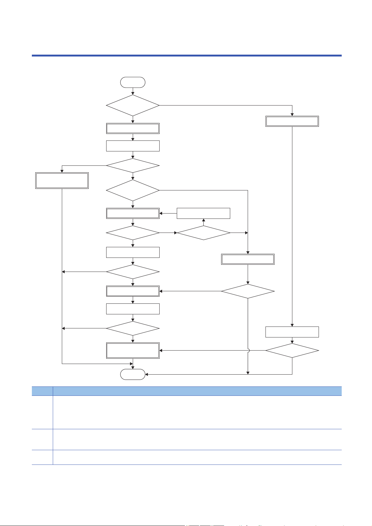
Adjust the servo amplifier with the following procedure.
No. Instructions
(1) Change [Pr. PA08.0 Gain adjustment mode selection] to "0".
(2) This mode can adjust the servo amplifier without driving the servo motor.
(3) Change the mode to the load to motor inertia ratio monitor mode if the adjustment result of the quick tuning has no problem.
2 ADJUSTMENT PROCEDURE
10
Use this mode to set the same setting value in [Pr. PB07 Model control gain] to all axes when performing interpolation such as path control or
tandem drive for a system with 2 axes or more.
Do not use this for other purposes.
Page 43 2 gain adjustment mode 1
Adjust the servo amplifier with this mode when not executing the interpolation control.
Page 12 Quick tuning
Page 12 Quick tuning

No. Instructions
(4) To start the one-touch tuning, push the "Start" button for one-touch tuning on the engineering tool during the positioning operation.
Use this adjustment if the conditions for the quick tuning are not fulfilled. A higher response level than that of the quick tuning can be obtained,
enabling a quicker positioning.
Page 16 One-touch tuning
(5) Set [Pr. PA08.0 Gain adjustment mode selection] to "1" or "2".
Page 37 Auto tuning mode 1
(6) [Pr. PA08.0 Gain adjustment mode selection] is automatically set to "4" (2 gain adjustment mode 2) once the one-touch tuning is complete.
Page 16 One-touch tuning
(7) Set [Pr. PA08.0 Gain adjustment mode selection] to "3".
Use the manual adjustment for fast settling or high accuracy path control.
Page 45 Manual mode
2
2 ADJUSTMENT PROCEDURE
11

3 ADJUSTMENT METHOD
3.1 Quick tuning
To use quick tuning, set [Pr. PA08.0 Gain adjustment mode selection] to "5". When the SON is on, the servo amplifier adjusts
the gain. The characteristic of quick tuning is shown as follows:
• Effective when to reduce the overshoot rather than to shorten the settling time because of the ability to reduce the
overshoot regardless of the machine type or the load size
• Adjustment available without the positioning operation
Restrictions on quick tuning
Quick tuning is not available in the following situations:
• During one-touch tuning
• In torque control
• When using adaptive filter II
Precautions on quick tuning
• Do not use quick tuning in a tandem system.
• Some noise due to the applied vibration torque may occur during quick tuning, but the noise is not an abnormality.
• When the load to motor inertia ratio is more than 100 times, quick tuning cannot adjust the gain appropriately. Adjust the
gain by using an alternative method such as auto tuning.
• When quick tuning is enabled (performed), the time until the servo amplifier actually becomes in the servo-on state after
turning on the servo-on command gets 300 ms longer at a maximum.
• When the torque limit value is less than 30 % of the rated torque, the torque required for quick tuning cannot be generated,
and quick tuning may fail. Set the torque limit value to exceed 30 % of the rated torque for quick tuning.
• If the travel distance in quick tuning exceeds the set value in [Pr. PA34 Quick tuning - Permissible travel distance], the
quick tuning will be stopped.
• [Pr. PB11 Speed differential compensation] will be changed to the initial value if quick tuning is used.
• When friction is 30 % or more of the rated torque, quick tuning may fail. In this case, adjust the gain with one-touch tuning
or auto tuning.
12
3 ADJUSTMENT METHOD
3.1 Quick tuning

Setting method for quick tuning
How to use quick tuning
Servo parameter Name Description
PA08.0 Gain adjustment mode selection Select the gain adjustment mode. The initial value is "1".
0: 2 gain adjustment mode 1 (interpolation mode)
1: Auto tuning mode 1
2: Auto tuning mode 2
3: Manual mode
4: 2 gain adjustment mode 2
5: Quick tuning mode
6: Load to motor inertia ratio monitor mode
PA08.4 Quick tuning - Load to motor
inertia ratio setting
PA08.5 Quick tuning - Execution selection Set when to execute quick tuning. The initial value is "0".
PA34 Quick tuning - Permissible travel
distance
Execute one-touch tuning with the following procedures.
Select the load to motor inertia ratio of the equipment. The initial value is "0".
0: A load to motor inertia ratio of 30 times or less
1: A load to motor inertia ratio of 100 times or less
0: At the initial servo-on after cycling the power (Execute quick tuning at the initial servo-on after
turning on the power)
1: At every servo-on (Execute quick tuning every time the SON is turned on.)
Set the permissible travel distance in quick tuning.
If the travel distance in quick tuning exceeds the setting value, the quick tuning error occurs.
When "0" is set, the permissible travel distance of quick tuning is 1.0 rev (10 mm when using a
linear servo motor).
Setting range: 0 to 100
3
■When executing quick tuning at the initial servo-on after turning on the power
1. Switch to the servo-off status.
2. Set "5" (quick tuning) to [Pr. PA08.0].
3. Set "0" (at the initial servo-on after cycling the power) to [Pr. PA08.5].
4. Check the load to motor inertia ratio.
• When the load to motor inertia ratio is 30 times or less
Set "0" (a load to motor inertia ratio of 30 times or less) to [Pr. PA08.4].
• When the load to motor inertia ratio is over 30 times and 100 times or less, or unknown
Set "1" (a load to motor inertia ratio of 100 times or less) to [Pr. PA08.4].
5. Set the permissible travel distance for quick tuning with [Pr. PA34].
6. Switch to the servo-on status to adjust servo parameters automatically.
Quick tuning will be executed at every initial servo-on after turning on the power thereafter.
7. Set "6" (load to motor inertia ratio monitor mode) to [Pr. PA08.0] to retain the tuning results.
3 ADJUSTMENT METHOD
3.1 Quick tuning
13

■When executing quick tuning at every servo-on
1. Switch to the servo-off status.
2. Set "5" (quick tuning) to [Pr. PA08.0].
3. Set "1" (at every servo-on) to [Pr. PA08.5].
4. Check the load to motor inertia ratio.
• When the load to motor inertia ratio is 30 times or less
Set "0" (a load to motor inertia ratio of 30 times or less) to [Pr. PA08.4].
• When the load to motor inertia ratio is 100 times or less, or unknown
Set "1" (a load to motor inertia ratio of 100 times or less) to [Pr. PA08.4].
5. Set the permissible travel distance for quick tuning with [Pr. PA34].
6. Switch to the servo-on status to adjust servo parameters automatically.
Quick tuning will be executed at every servo-on thereafter.
7. Set "6" (load to motor inertia ratio monitor mode) to [Pr. PA08.0] to retain the tuning results.
How to restore servo parameters before quick tuning
Servo parameter Name Description
PA08.6 Quick tuning - Restore selection Set whether to restore the servo parameter values before quick tuning. The initial value is "0".
0: Disabled
1: Enabled
When [Pr. PA08.6] is set to "1" (Enabled), the following servo parameters return to the values before quick tuning. If quick
tuning has never been performed after power on or software reset, setting [Pr. PA08.6] to "1" only keeps the current servo
parameters.
No. Symbol Name
PB01 FILT Adaptive tuning mode (adaptive filter II)
PB07 PG1 Model control gain
PB08 PG2 Position control gain
PB09 VG2 Speed control gain
PB10 VIC Speed integral compensation
PB11 VDC Speed differential compensation
PB13 NH1 Machine resonance suppression filter 1
PB14 NHQ1 Notch shape selection 1
PB15 NH2 Machine resonance suppression filter 2
PB16 NHQ2 Notch shape selection 2
PB18 LPF Low-pass filter setting
PB23 VFBF Low-pass filter selection
PB50 NH5 Machine resonance suppression filter 5
PB51 NHQ5 Notch shape selection 5
PE41 EOP3 Function selection E-3
14
3 ADJUSTMENT METHOD
3.1 Quick tuning
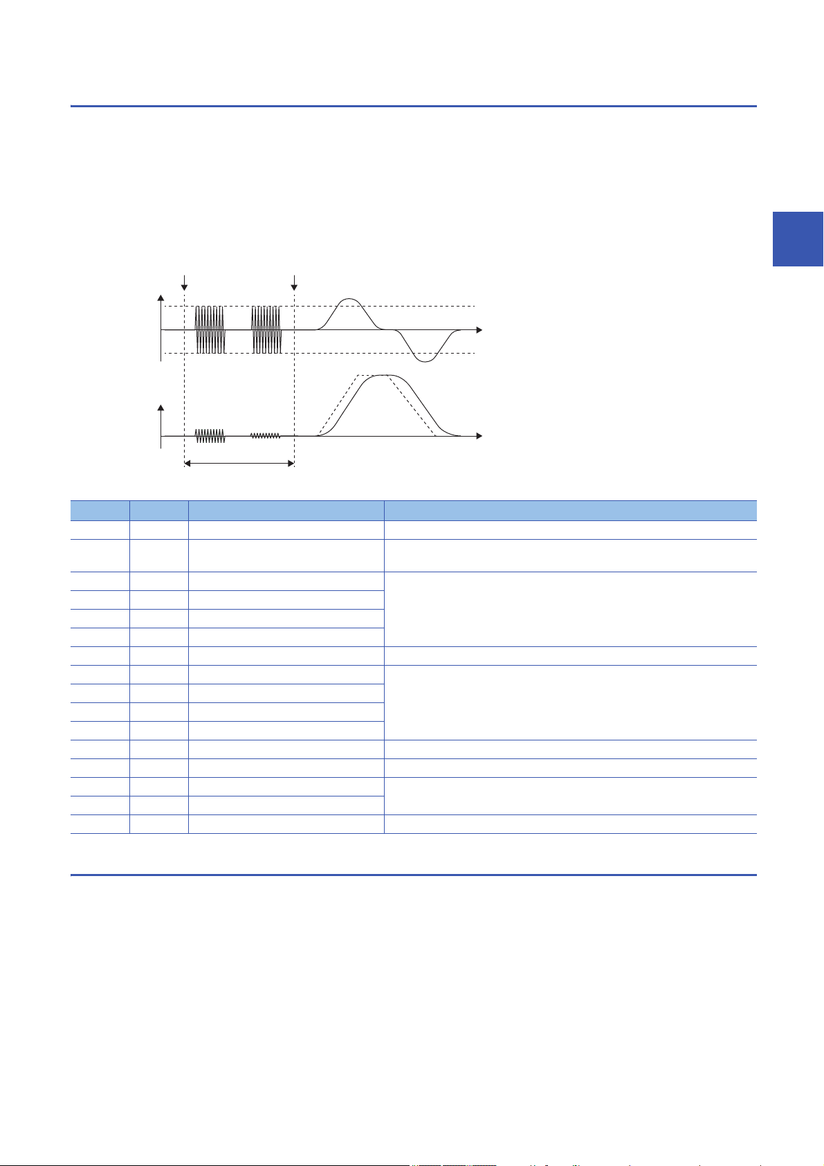
Operation of quick tuning
Start of quick tuning Gain adjustment complete
Torque
60 % of rated
torque
Time
-60 % of rated
torque
Speed
Time
Approx. 300 [ms]
When quick tuning is started, the servo amplifier applies vibration torque instantly, and adjusts each gain and the machine
resonance suppression filter by using the response from that excitation. Vibration torque is applied by 60 % at the maximum
of the rated torque. However, vibration torque is limited by the torque limit value when the torque limit value is less than 60 %
of the rated torque. The adjusting time is approximately 300 [ms]. When the magnetic pole detection is executed, quick tuning
will be started after the magnetic pole detection.
Once gain adjustment by quick tuning is complete, the gain can be changed as in the manual mode. Also, the load to motor
inertia ratio will be always estimated as in the auto tuning mode 1 after the gain adjustment.
The following servo parameters are adjusted automatically in quick tuning.
No. Symbol Name Setting value after gain adjustment
PB01 FILT Adaptive tuning mode (adaptive filter II) Automatic setting
PB06 GD2 Load to motor inertia ratio The setting value is set depending on the response waveform during servo motor
driving after gain adjustment.
PB07 PG1 Model control gain Automatic setting
PB08 PG2 Position control gain
PB09 VG2 Speed control gain
PB10 VIC Speed integral compensation
PB11 VDC Speed differential compensation Initial value
PB13 NH1 Machine resonance suppression filter 1 Automatic setting
PB14 NHQ1 Notch shape selection 1
PB15 NH2 Machine resonance suppression filter 2
PB16 NHQ2 Notch shape selection 2
PB18 LPF Low-pass filter setting Initial value
PB23.1 Low-pass filter selection 1
PB50 NH5 Machine resonance suppression filter 5 Automatic setting
PB51 NHQ5 Notch shape selection 5
PE41 EOP3 Function selection E-3 Initial value
3
Errors in quick tuning
When the following conditions are met, quick tuning may fail:
• When torque is reached to torque limit value during quick tuning
• When the travel distance in quick tuning exceeds the set value in [Pr. PA34 Quick tuning - Permissible travel distance]
When quick tuning fails, the servo parameters before quick tuning will be restored.
3 ADJUSTMENT METHOD
3.1 Quick tuning
15

3.2 One-touch tuning
Precautions
By turning on the one-touch tuning during servo motor operation, the one-touch tuning performs an adjustment in accordance
with the machine characteristic. The one-touch tuning has two methods: the user command method and the amplifier
command method.
User command method
The user command method performs the one-touch tuning by inputting commands from outside the servo amplifier. Although
it is necessary to input commands from the outside of the servo amplifier, the optimum adjustment can be made by taking both
the mechanical characteristics and the commands into accounts.
Amplifier command method
The amplifier command method generates an optimum tuning command inside a servo amplifier and performs the one-touch
tuning by simply inputting travel distance (permissible travel distance) that avoids collision with the machine during servo
motor driving. The one-touch tuning in this method can be performed easier than the user command method, and does not
require to generate commands from the outside of a servo amplifier. However, MR Configurator2 is required for performing
the one-touch tuning in the amplifier command method.
• When the following servo parameters are set in [Pr. PA08.0 Gain adjustment mode selection], [Pr. PB06 Load to motor
inertia ratio/load to motor mass ratio] is estimated at the start of one-touch tuning.
"0" (2 gain adjustment mode 1 (interpolation mode))
"1" (Auto tuning mode 1)
"2" (Auto tuning mode 2)
"4" (2 gain adjustment mode 2)
"6" (Load to motor inertia ratio monitor mode)
Restrictions on one-touch tuning
The one-touch tuning cannot be performed in the following conditions.
Common restrictions on user command method and amplifier command method
• When [Pr. PA21.0 One-touch tuning - Function selection] is "0" (disabled)
• In the torque mode
• When an alarm or a warning which disrupts the motor driving occurs
• In output signal (DO) forced output and motor-less operation
Restrictions on user command method
• The one-touch tuning in the user command method cannot be performed at servo-off.
Restrictions on amplifier command method
• The one-touch tuning in the amplifier command method cannot be started during servo motor driving.
• The one-touch tuning in the amplifier command method cannot be performed when the positioning operation, JOG
operation, program operation, and test operation mode of machine analyzer function are being carried out.
16
3 ADJUSTMENT METHOD
3.2 One-touch tuning

Instructions on one-touch tuning
Instructions on amplifier command method
• Once one-touch tuning is performed, control by commands from a controller will not be available. To enable control from the
controller again, reset the controller, cycle the power of the servo amplifier, or reset software.
• Set the permissible travel distance for not to collide with a machine. In addition, the permissible travel distance may be
exceeded because of an overshoot during one-touch tuning. Therefore, set the permissible travel distance with a margin to
avoid exceeding the range of a limit switch.
• When the manual mode is selected in [Pr. PA08.0 Gain adjustment mode selection], a load to motor inertia ratio is not
estimated. Optimum acceleration/deceleration commands are generated by [Pr. PB06 Load to motor inertia ratio/load to
mass ratio] at the start of the one-touch tuning. When the load to motor inertia ratio is not accurate, optimum acceleration/
deceleration commands may not be generated, causing the tuning to fail.
• When the one-touch tuning is started by using USB communication, if the communication between MR Configurator2 and a
servo amplifier is interrupted during the tuning, both the servo motor and the tuning stop. In addition, the servo parameters
returns to the status at the start of one-touch tuning.
• When the one-touch tuning starts during the velocity mode, the mode is switched to the position mode automatically. As a
result, the tuning result may differ from the results obtained by using the speed command.
One-touch tuning procedure
3
Procedure for one-touch tuning in user command method by MR Configurator2
Perform the one-touch tuning with the following procedure.
1. Start
2. Overshoot permissible level setting
Set the permitted overshoot level for the one-touch tuning in [Pr. PA25 One-touch tuning - Permitted overshoot level].
3. Operation
Rotate a servo motor by a controller. In the user command method, the one-touch tuning cannot be performed during a servo
motor stop.
4. One-touch tuning start, mode selection
On MR Configurator2, select "One-touch tuning" from the tuning tab of MR Configurator2. Select "User command method".
5. Response mode selection
Select the response mode (High mode/Basic mode/Low mode) in the one-touch tuning window of MR Configurator2.
6. One-touch tuning execution
Click “Start” during servo motor driving.
7. One-touch tuning in progress
Gains and filters are adjusted automatically. During the process of the tuning, the progress status is displayed in % on MR
Configurator2.
8. One-touch tuning complete
Once one-touch tuning is complete, the parameters will be set automatically. If tuning did not complete properly, a tuning error
will be displayed.
Page 29 Servo parameters adjusted with one-touch tuning
9. Tuning result check
Check the tuning results.
When the tuning result is not satisfactory, the servo parameters can be returned to the value before the one-touch tuning or
the initial value.
Page 34 Initializing one-touch tuning
10. End
3 ADJUSTMENT METHOD
3.2 One-touch tuning
17
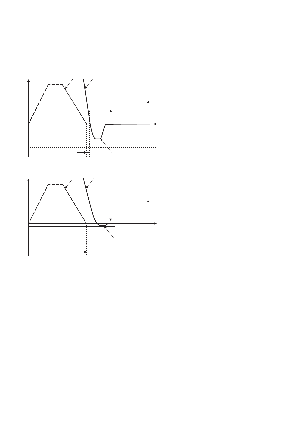
■Overshoot permissible level setting
[Pr. PA14]
[Pr. PA14]
× [Pr. PA25]
Position command frequency
Droop pulses
Reduced settling time
Increased overshoot
[Pr. PA14]
[Pr. PA14]
× [Pr. PA25]
Position command frequency Droop pulses
Reduced overshoot
Increased settling time
Set the permitted overshoot level for the one-touch tuning in [Pr. PA25 One-touch tuning - Permitted overshoot level]. The
one-touch tuning adjusts the settling time to the shortest within the range of the overshoot permissible level. Therefore, when
the value set in [Pr. PA25] is large, reduction of the settling time is prioritized. When the value set in [Pr. PA25] is small, then
reduction of the overshoot is prioritized.
• When the permitted overshoot level is high
• When the permitted overshoot level is low
18
3 ADJUSTMENT METHOD
3.2 One-touch tuning
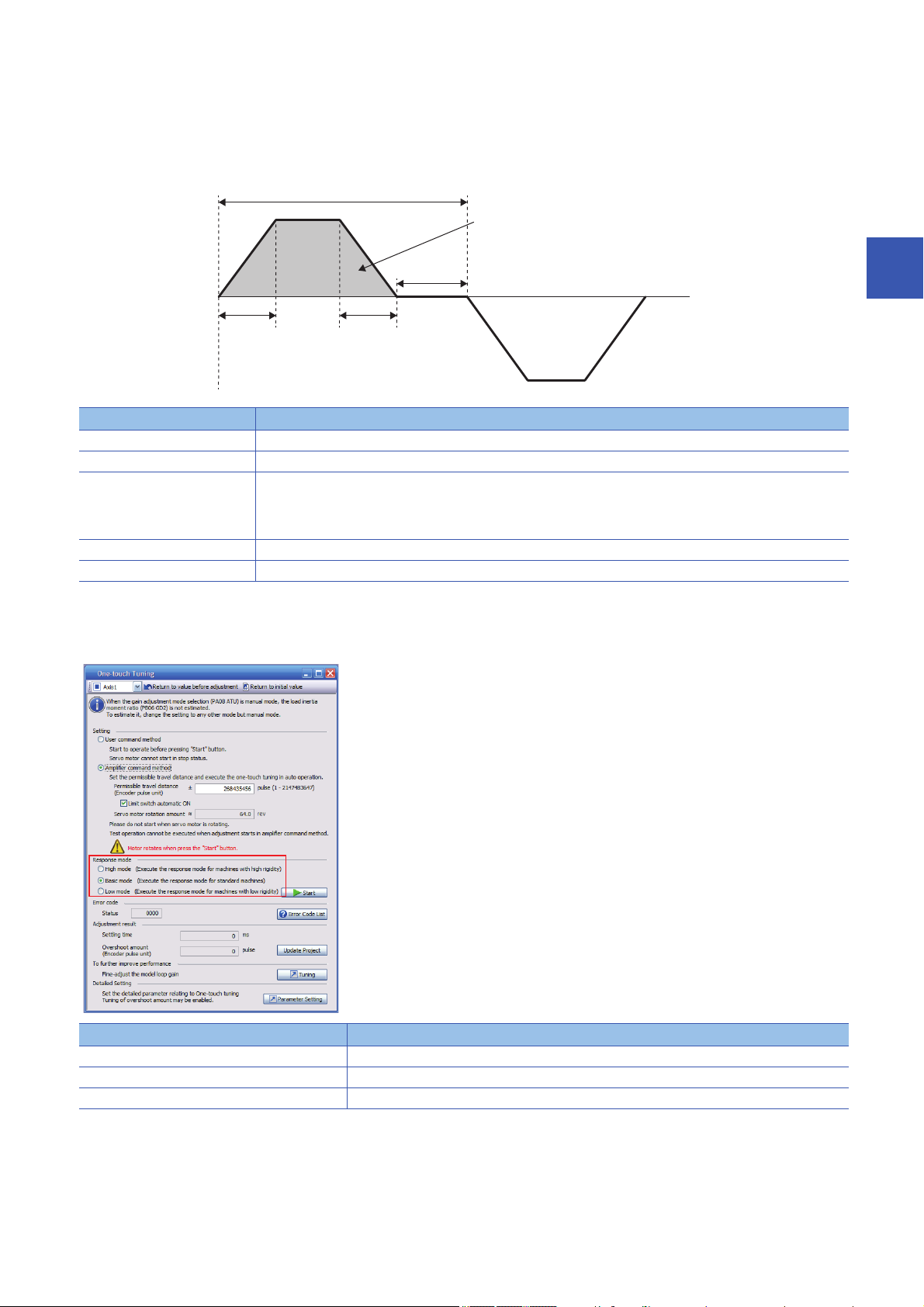
■Operation
0 r/min
One cycle time
Forward rotation
Travel distance
Dwell time
Servo motor
speed
Acceleration
time constant
Deceleration
time constant
Reverse rotation
Inputting commands to the servo amplifier that satisfy the following conditions is recommended. If the one-touch tuning is
performed with commands that do not satisfy the condition are inputted to the servo amplifier, a one-touch tuning error may
occur.
Item Description
Travel distance Set 100 pulses or more in the encoder pulse unit. Setting less than 100 pulses causes the one-touch tuning error "C_04".
Servo motor speed Set 50 r/min (mm/s) or higher. Setting less than 50 r/min may cause the one-touch tuning error "C_05".
Acceleration time constant
Deceleration time constant
Dwell time Set 200 ms or more. If the value is small, the one-touch tuning error "C_04" may occur.
One cycle time Set 30 s or less. Setting over 30 s causes the one-touch tuning error "C_04".
Set the time to reach 2000 r/min (mm/s) to 5 s or less.
Set an acceleration time constant/deceleration time constant so that the acceleration/deceleration torque is 10 % or more
of the rated torque. The estimation accuracy of the load to motor inertia ratio improves as the acceleration/deceleration
torque is larger, and the one-touch tuning result is closer to the optimum value.
3
■Command method and response mode selection
Select the user command method in the one-touch tuning window of MR Configurator2 and then select a response mode from
three modes. If no vibration sound occurs during tuning, perform the one-touch tuning again in the high response mode.
Item Description
High mode This mode is for a high-rigid system.
Basic mode This mode is for a standard system.
Low mode This mode is for a low-rigid system.
3 ADJUSTMENT METHOD
3.2 One-touch tuning
19
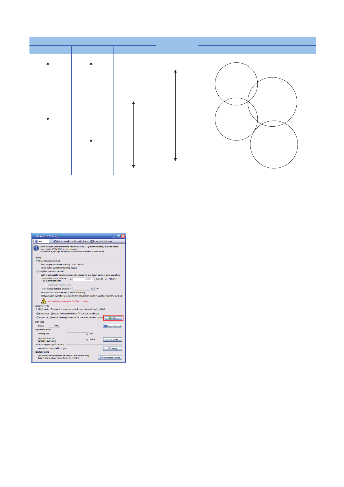
Refer to the following table for selecting a response mode.
Low response
High response
Response mode Responsiveness Machine characteristic
Low mode Basic mode High mode Guidelines for corresponding mode and machinery
Arm robot
General machine tool
Conveyor
Precision working
machine
Inserter
Mounter
Bonder
■One-touch tuning execution
Clicking "Start" after selecting a response mode starts the one-touch tuning in the user command method.
Page 19 Command method and response mode selection
For the one-touch tuning in the user command method, clicking "Start" during a servo motor stop causes "C_02" or "C_04"
shown at the status of the error code. (Refer to the following for the error code.)
Page 31 One-touch tuning error
20
3 ADJUSTMENT METHOD
3.2 One-touch tuning

Procedure of one-touch tuning in the amplifier command method with MR
Configurator2
Perform the one-touch tuning with the following procedure.
1. Start
2. Moving to tuning start position
Move the moving part to the center of the movable range.
3. Overshoot permissible level setting
Set the permitted overshoot level for the one-touch tuning in [Pr. PA25 One-touch tuning - Permitted overshoot level].
4. One-touch tuning start, mode selection
On MR Configurator2, select "One-touch tuning" from the tuning tab of MR Configurator2. Select "Amplifier command
method".
5. Permissible travel distance input
In the one-touch tuning window of MR Configurator2, input a maximum travel distance to move the moving part at one-touch
tuning.
6. Response mode selection
Select the response mode (High mode/Basic mode/Low mode) in the one-touch tuning window of MR Configurator2.
7. One-touch tuning execution
Click the "Start" button to start the one-touch tuning during a servo motor stop. On starting the tuning , the servo motor
reciprocates automatically. Performing the one-touch tuning during a servo motor rotation causes an error. Once performed,
the one-touch tuning in the amplifier command method cannot be controlled by commands from the controller.
8. One-touch tuning in progress
Gains and filters are adjusted automatically. During the process of the tuning, the progress status is displayed in % on MR
Configurator2.
9. One-touch tuning complete
Once one-touch tuning is complete, the parameters will be set automatically. When the tuning is not completed normally, a
tuning error is displayed.
Page 29 Servo parameters adjusted with one-touch tuning
3
10. Tuning result check
Check the tuning results.
When the tuning result is not satisfactory, the servo parameters can be returned to the value before the one-touch tuning or
the initial value. Refer to the following.
Page 34 Initializing one-touch tuning
11. Controller reset, servo amplifier power cycling
After executing the one-touch tuning, to restore the control from the controller, reset the controller or cycle the power of the
servo amplifier.
12. End
■Overshoot permissible level setting
Refer to the following for the settings of overshoot permissible level.
Page 18 Overshoot permissible level setting
3 ADJUSTMENT METHOD
3.2 One-touch tuning
21
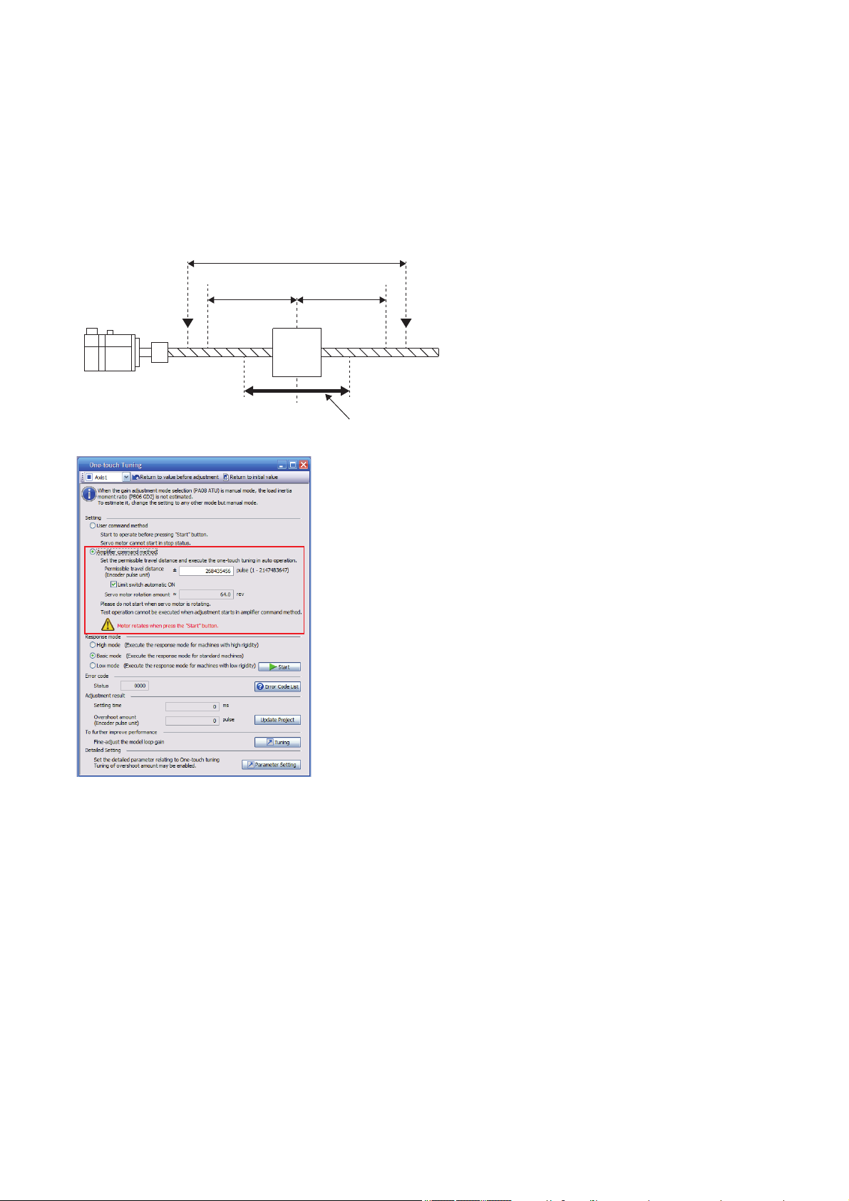
■Mode selection and permissible travel distance input
Movable range
Permissible travel
distance
Permissible travel
distance
Limit switch Limit switch
Moving
part
Servo motor
Starting position
of tuning
Movable range at tuning
Select "Amplifier command method" in the one-touch tuning window of MR Configurator2. Input permissible travel distance of
the amplifier command method. For the fully closed loop control mode, input permissible travel distance in the load-side
resolution unit. For other control modes, input it in the servo motor-side resolution unit. In the amplifier command method, a
servo motor drives in a range between "current value ± permissible travel distance". Input the value of the permissible travel
distance as large as possible within a range that the movable part does not collide against the machine. Inputting a small
permissible travel distance decreases the possibility that the moving part collides against the machine. However, the
estimation accuracy of the load to motor inertia ratio may be lower, resulting in inaccurate tuning.
■Response mode selection
Refer to the following for response mode.
Page 19 Command method and response mode selection
22
3 ADJUSTMENT METHOD
3.2 One-touch tuning
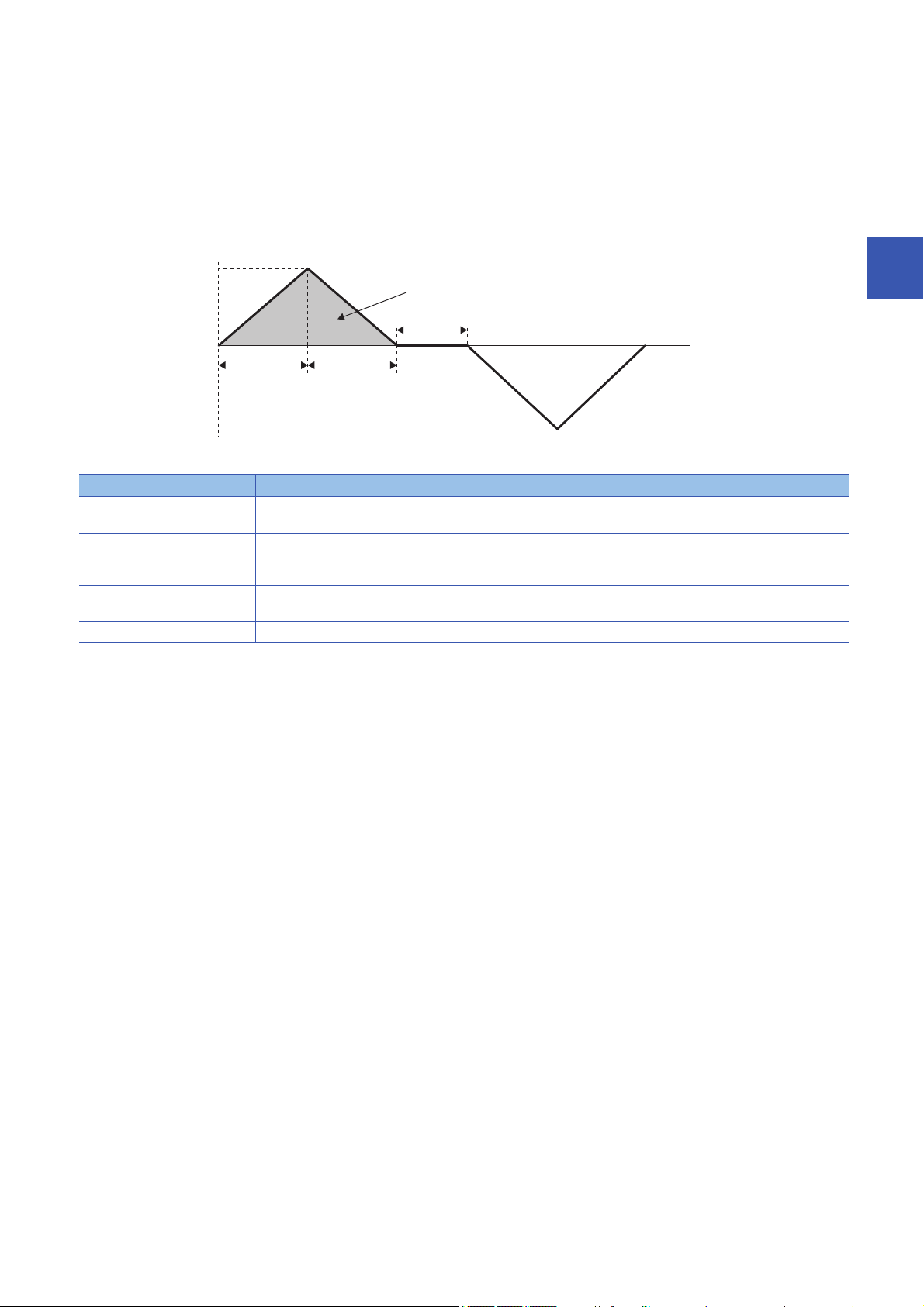
■One-touch tuning execution
0 r/min
Servo motor
speed
*1
Travel distance
*1
Forward rotation
Dwell time
*1
Servo motor
speed
Acceleration time
constant
*1
Deceleration time
constant
*1
Reverse rotation
Clicking "Start" after selecting a response mode starts the one-touch tuning in the amplifier command method.
Page 19 Command method and response mode selection
In servo-off status, clicking "Start" for the one-touch tuning in the amplifier command method, servo-on is automatically
enabled and the one-touch tuning starts. For the one-touch tuning in the amplifier command method, an optimum tuning
command as follows is generated inside the servo amplifier after servo-on. Then the one-touch tuning is performed with the
servo motor reciprocating.
*1 These items are automatically generated in the servo amplifier.
Item Description
Travel distance An optimum travel distance is automatically set in the range not exceeding the user-inputted permissible travel distance
with MR Configurator2.
Servo motor speed [A]: A speed not exceeding 1/2 of the rated speed and the overspeed alarm detection level is automatically set.
[G] [WG]: A speed not exceeding 1/2 of the rated speed and the overspeed alarm detection level ([Pr. PC08]) is
automatically set.
Acceleration time constant
Deceleration time constant
Dwell time A dwell time in which the one-touch tuning error "C004" does not occur will be automatically set.
An acceleration time constant/deceleration time constant is automatically set so as not to exceed 60 % of the rated torque
and the torque limit value set at the start of one-touch tuning in the amplifier command method.
3
3 ADJUSTMENT METHOD
3.2 One-touch tuning
23

Procedure of one-touch tuning via controller [G] [WG]
Perform the one-touch tuning with the following procedure.
1. Start
2. Overshoot permissible level setting
Set the in-position range for one-touch tuning in [Pr. PA25 One-touch tuning - Permitted overshoot level].
3. Operation
Rotate a servo motor by a controller. The one-touch tuning via a controller cannot be performed during a servo motor stop.
4. Response mode setting, one-touch tuning execution
To perform the one-touch tuning, write the value of the response mode (High mode/Basic mode/Low mode) in [One-touch
tuning mode (Obj. 2D50h)].
5. One-touch tuning in progress
Gains and filters are adjusted automatically. During one-touch tuning, the progress is returned to [One-touch tuning Status
(Obj. 2D51h)] in %.
6. One-touch tuning complete
Check whether the one-touch tuning is completed normally with [One-touch tuning mode (Obj. 2D50h)]. Once one-touch
tuning is complete, each parameter will be set automatically. When the tuning is not completed normally, a tuning error is
returned in [One-touch tuning Error Code (Obj. 2D54h)]. Refer to the following.
Page 34 Initializing one-touch tuning
7. Tuning result check
Check the tuning results.
If the tuning result is not satisfactory, the servo parameters can be returned to the value before the one-touch tuning or the
initial value with [One-touch tuning Clear (Obj. 2D53h)]. Refer to the following.
Page 34 Initializing one-touch tuning
8. End
24
3 ADJUSTMENT METHOD
3.2 One-touch tuning

■Object registration
Register the following objects when performing the one-touch tuning.
Index Sub Object Name Data
Type
2D50h 0 VAR One-touch tuning mode U8 rw 0 Setting "1", "2", or "3" starts one-touch
2D51h 0 VAR One-touch tuning Status I8 ro 0 Regardless of whether the one-touch tuning
2D52h 0 VAR One-touch tuning Stop U16 wo 0 Writing "1EA5h" stops one-touch tuning.
2D53h 0 VAR One-touch tuning Clear U16 wo 0 Servo parameters that were changed in the
2D54h 0 VAR One-touch tuning Error
Code
U16 ro 0 The following shows the details of the one-
Access Default Description
tuning. After one-touch tuning is completed,
the setting value automatically changes to
"0".
0: During one-touch tuning stop
1: Basic mode
2: High mode
3: Low mode
is properly completed or not, the setting
value is 100 % at the completion.
Unit: %
one-touch tuning can be restored to the
original status.
0000h: Restores factory setting
0001h: Restores the value before one-touch
tuning
When servo parameters are restored, the
setting value of the restored servo
parameter is stored to the EEP-ROM.
touch tuning error codes.
0000h: Properly completed
C_00h: Tuning canceled
C_01h: Overshoot exceeded
C_02h: Servo OFF during tuning
C_03h: Control mode error
C_04h: Time-out
C_05h: Load to motor inertia ratio
miscalculated
C_06h: Servo amplifier built-in command
start error
C_07h: Servo amplifier built-in command
generation error
C_08h: Stop signal
C_09h: Parameter
C_0Ah: Alarm
C00Fh: One-touch tuning disabled
3
■Overshoot permissible level setting
Refer to the following for the settings of an overshoot permissible level.
Page 18 Overshoot permissible level setting
■Operation
Refer to the following for operation.
Page 19 Operation
■Response mode selection
Refer to the following for response mode.
Page 19 Command method and response mode selection
3 ADJUSTMENT METHOD
3.2 One-touch tuning
25

One touch adjustment procedure with push button [A]
Perform the one-touch tuning with the following procedure.
1. Start
2. Overshoot permissible level setting
Set the in-position range for one-touch tuning in [Pr. PA25 One-touch tuning - Permitted overshoot level].
3. Operation
Rotate a servo motor by a controller. In the user command method, the one-touch tuning cannot be performed during a servo
motor stop.
4. Switching to one-touch tuning mode
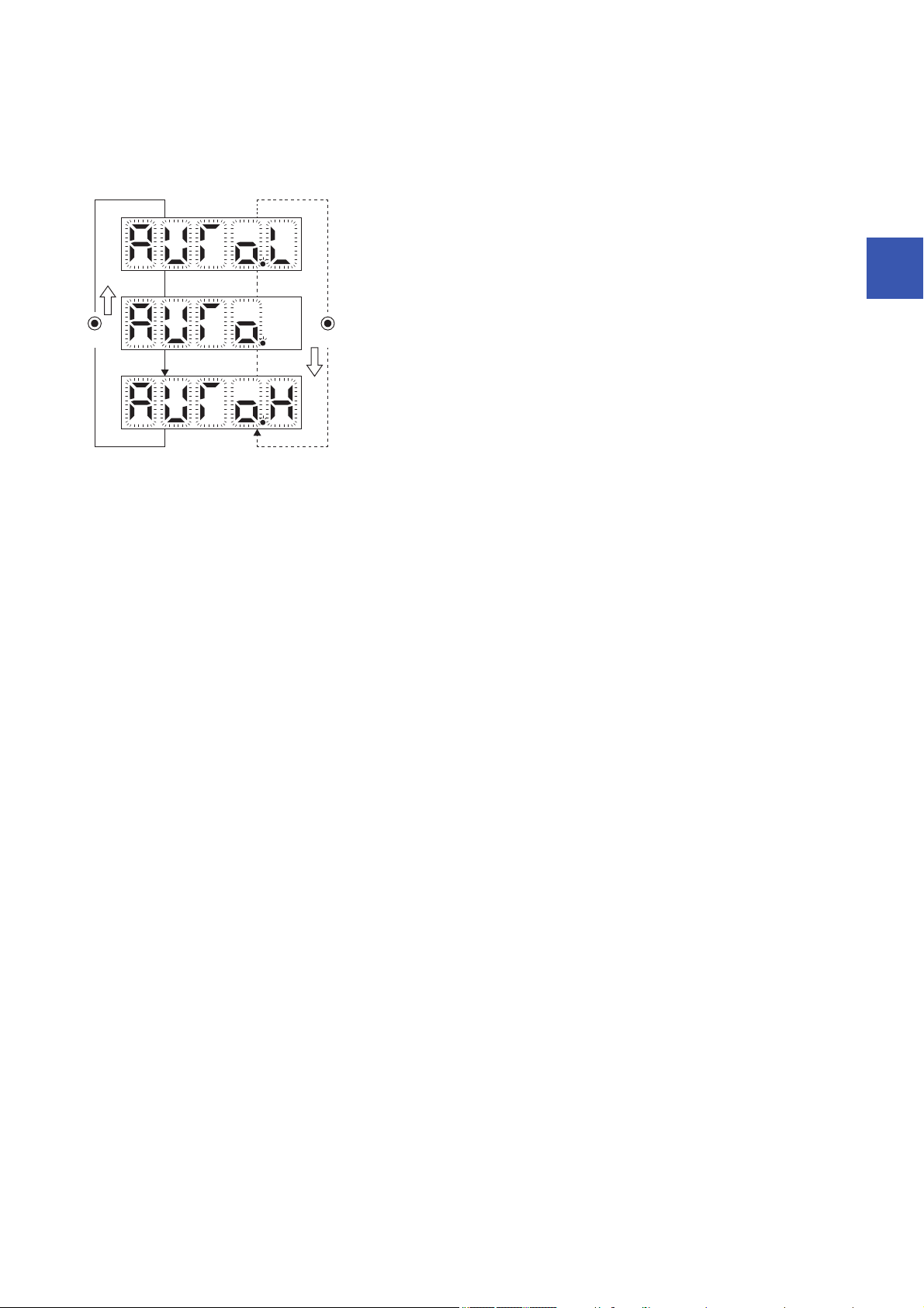
Push "MODE" during motor driving to switch to the initial screen ("AUTO.") of the one-touch tuning. While "AUTO" is being
displayed, push the "SET" button for 2 s or more to switch to the response mode selection ("AUTO.").
By pushing "MODE" and "SET" at the same time for 3 s or more, switching to the response mode selection ("AUTO.") can be
done without going through the initial display of the one-touch tuning ("AUTO").
5. Response mode selection
Push the "UP" or "DOWN" , and select either one of the response mode from "AUTO.H" (High mode), "AUTO." (Basic mode),
and "AUTO.L" (Low mode).
6. One-touch tuning execution
Push "SET" to start the one-touch tuning. Push the "SET" during servo motor driving.
7. One-touch tuning in progress
Gains and filters are adjusted automatically. During the process of tuning, the progress status is displayed in % on the display
(five-digit, seven-segment LED).
8. One-touch tuning complete
Once one-touch tuning is complete, each parameter will be set automatically. When the tuning is not completed normally, a
tuning error is displayed. Refer to the following.
Page 34 Initializing one-touch tuning
9. Tuning result check
Check the tuning results.
When the tuning result is not satisfactory, the servo parameters can be returned to the value before the one-touch tuning or
the initial value.
Page 34 Initializing one-touch tuning
10. End
■Overshoot permissible level setting
Refer to the following for the settings of the overshoot permissible level.
Page 18 Overshoot permissible level setting
■Operation
Refer to the following for operation.
Page 19 Operation
26
3 ADJUSTMENT METHOD
3.2 One-touch tuning
■Response mode selection
DOWN
UP
Response mode selection display
Low mode : This mode is for a low-rigid system.
Basic mode : This mode is for a standard system.
High mode : This mode is for a high-rigid system.
Select a response mode of the one-touch tuning from three modes with the "UP" button or the "DOWN" button. Refer to the
following for guidelines of response mode.
Page 19 Command method and response mode selection
■One-touch tuning execution
After the response mode is selected, pushing "SET" starts one-touch tuning.
Page 19 Command method and response mode selection
3
3 ADJUSTMENT METHOD
3.2 One-touch tuning
27

Progress display during one-touch tuning
On MR Configurator2
In servo-off status, clicking "Start" for one-touch tuning in the amplifier command method, servo-on is automatically enabled
and the one-touch tuning starts. For the one-touch tuning in the amplifier command method, an optimum tuning command is
generated inside the servo amplifier after servo-on. Then the one-touch tuning is performed with the servo motor
reciprocating. After the tuning is completed or canceled, the servo amplifier is automatically switched to the servo-off status.
When the servo-on command has been input from outside, the servo amplifier maintains the servo-on state.
During one-touch tuning, the progress status is displayed in the progress window as follows. One-touch tuning completes
when the progress reaches 100 %.
Completing the one-touch tuning starts the writing of servo parameters to the servo amplifier. Also, the following dialog is
displayed after completing the one-touch tuning. Select whether or not to reflect the tuning result in the project.
After the one-touch tuning is completed, "0000" is displayed in the status of the error code. Settling time and overshoot
amount are displayed in "Adjustment result".
28
3 ADJUSTMENT METHOD
3.2 One-touch tuning

On a controller [G] [WG]
One-touch tuning
in progress
The progress of the one-touch tuning is represented from 0 % to 100 %.
The decimal point moves right to left in rotation during the tuning.
Pushing the "MODE" button during the tuning switches to the status display.
Complete
Once the one-touch tuning is complete, the auto-tuned parameters
by the one-touch tuning will be written to the servo amplifier.
The progress of one-touch tuning can be checked with [One-touch tuning Status (Obj. 2D51h)] during one-touch tuning. When
the progress reaches 100 %, the one-touch tuning is completed and [One-touch tuning mode (Obj. 2D50h)] switches to "0".
With push buttons [A]
The following are displayed during the one-touch tuning.
3
Servo parameters adjusted with one-touch tuning
The following servo parameters are set automatically with the one-touch tuning. Moreover, [Pr. PA08.0 Gain adjustment mode
selection] is set to "4" (2 gain adjustment mode 2) automatically. Other servo parameters are set to an optimum value in
accordance with the setting of [Pr. PA09 Auto tuning response].
Servo parameter Symbol Name
PA08 ATU Auto tuning mode
PA09 RSP Auto tuning response
PA24 AOP4 Function selection A-4
PB01 FILT Adaptive tuning mode (adaptive filter II)
PB02 VRFT Vibration suppression control tuning mode (advanced vibration suppression control II)
PB03 PST Position command - Acceleration/deceleration time constant (position smoothing)
PB06 GD2 Load to motor inertia ratio/load to motor mass ratio
PB07 PG1 Model control gain
PB08 PG2 Position control gain
PB09 VG2 Speed control gain
PB10 VIC Speed integral compensation
PB12 OVA Overshoot amount compensation
PB13 NH1 Machine resonance suppression filter 1
PB14 NHQ1 Notch shape selection 1
PB15 NH2 Machine resonance suppression filter 2
PB16 NHQ2 Notch shape selection 2
PB17 NHF Shaft resonance suppression filter
PB18 LPF Low-pass filter setting
PB19 VRF11 Vibration suppression control 1 - Vibration frequency
PB20 VRF12 Vibration suppression control 1 - Resonance frequency
PB21 VRF13 Vibration suppression control 1 - Vibration frequency damping
PB22 VRF14 Vibration suppression control 1 - Resonance frequency damping
PB23 VFBF Low-pass filter selection
3 ADJUSTMENT METHOD
3.2 One-touch tuning
29

Servo parameter Symbol Name
Stop symbol
Once the one-touch tuning mode is in progress, the one-touch tuning mode can be stopped
by pushing the "SET" button regardless of what is displayed on the screen.
2 s interval
The stop symbol and error code "C 000" (cancel during tuning) will be displayed by turns
with 2 s interval.
After the one-touch tuning is stopped, the servo parameters are restored to the values
at the start of the one-touch tuning.
Error code
Pushing the "SET" button will switch to the initial screen.
Initial screen
When performing the one-touch tuning again, stop the servo motor once.
PB46 NH3 Machine resonance suppression filter 3
PB47 NHQ3 Notch shape selection 3
PB48 NH4 Machine resonance suppression filter 4
PB49 NHQ4 Notch shape selection 4
PB51 NHQ5 Notch shape selection 5
PB52 VRF21 Vibration suppression control 2 - Vibration frequency
PB53 VRF22 Vibration suppression control 2 - Resonance frequency
PB54 VRF23 Vibration suppression control 2 - Vibration frequency damping
PB55 VRF24 Vibration suppression control 2 - Resonance frequency damping
PE41 EOP3 Function selection E-3
One-touch tuning stop method
On MR Configurator2
Clicking the "Stop" button during tuning stops one-touch tuning. If one-touch tuning is stopped, "C000" will be displayed in the
error code status. After the one-touch tuning is stopped, the servo parameters are restored to the values at the start of the
one-touch tuning. When performing the one-touch tuning again, stop the servo motor once. In addition, perform the one-touch
tuning after the moving part is returned to the tuning start position.
On a controller [G] [WG]
Writing "1EA5" in [One-touch tuning Stop (Obj. 2D52h)] during the one-touch tuning stops the tuning. After the one-touch
tuning is stopped, the servo parameters are restored to the values at the start of the one-touch tuning. Moreover when
performing the one-touch tuning again, stop the servo motor once.
With push buttons [A]
30
3 ADJUSTMENT METHOD
3.2 One-touch tuning

One-touch tuning error
On MR Configurator2
If a tuning error occurs during the tuning, the one-touch tuning is stopped. At this time, as the error code is displayed in the
error code status, check the cause of the tuning error. Stop the servo motor before executing one-touch tuning again. In
addition, perform the one-touch tuning after the moving part is returned to the tuning start position.
Display Name Error description Handling example
C000 Tuning canceled The "Stop" button was clicked during one-touch
C_01 Overshoot exceeded The overshoot amount is larger than the value set in
C_02 Servo OFF during tuning The one-touch tuning in the user command method
C_03 Control mode error The one-touch tuning was attempted when the
C_04 Time-out One cycle time during the operation exceeds 30 s. Set one cycle time during the operation (time from the
C_05 Load to motor inertia
ratio miscalculated
C_06 Amplifier command start
error
tuning.
[Pr. PA10 In-position range] and [Pr. PA25 Onetouch tuning - Permitted overshoot level].
was attempted during servo-off.
The servo amplifier was set to the servo-off status
during the one-touch tuning.
torque mode was selected in the control modes.
Control switching from the position mode to the
speed mode was attempted during one-touch tuning.
The command speed is slow. Set the servo motor speed to 100 r/min (mm/s) or higher. An
The dwell time during continuous operation (stop
time between commands) is short.
The estimation of the load to motor inertia ratio at the
one-touch tuning has failed.
The load to motor inertia ratio cannot be estimated
due to the effect of oscillation or others.
One-touch tuning was attempted to start by the
amplifier command method under the following
speed condition.
• Servo motor speed: 20 [r/min] or higher
• In MR-J5W-G, servo motor speed of other axes:
20 [r/min] or higher
Increase the in-position range or the overshoot permissible
level.
Perform the one-touch tuning in the user command method in
servo-on status.
Do not turn the servo off during one-touch tuning.
Select the position mode or velocity mode for the control mode,
and then perform the one-touch tuning without control
switching.
command start to the next command start) to 30 s or less.
error is less likely to occur if the command speed is higher.
Set the dwell time to 200 ms or more.
An error is less likely to occur as the setting time is longer.
Drive the servo motor under the following conditions:
• Time to reach 2000 r/min (mm/s) is the acceleration/
deceleration time constant of 5 s or less.
• Speed is 50 r/min (mm/s) or higher.
• The load to motor inertia ratio to the servo motor is 100 times
or less.
• The acceleration/deceleration torque is 10 % or more of the
rated torque.
Set [Pr. PA08.0 Gain adjustment mode selection] to "3" (manual
mode), and set the correct value of load inertia moment ratio to
[Pr. PB06 Load to motor inertia ratio], then execute the onetouch tuning.
Perform the one-touch tuning in the amplifier command method
when the servo motor is at a stop.
3
3 ADJUSTMENT METHOD
3.2 One-touch tuning
31

Display Name Error description Handling example
C_07 Amplifier command
generation error
C_08 Stop signal LSP and LSN were turned off during the one-touch
C_09 Parameter Servo parameter for manufacturer setting has been
C_0A Alarm The one-touch tuning in the amplifier command
C00F One-touch tuning
disabled
The one-touch tuning (amplifier command) was
performed when the permissible travel distance was
set to 100 [pulse] or less in the encoder pulse unit, or
the servo motor speed was set to less than 50 [r/min]
(for direct drive motors, less than 15 [r/min]) at the
load to motor inertia ratio estimation.
The overspeed alarm detection level is set where the
servo motor speed becomes 50 [r/min] or less (for
direct drive motors, 15 [r/min] or less) at the time of
load to motor inertia ratio estimation.
The torque limit value has been set to 0. Set the torque limit value greater than 0.
tuning of the amplifier command method.
EM2 was turned off during the one-touch tuning in
the amplifier command method.
changed.
method was attempted to start during an alarm or a
warning occurrence.
An alarm or a warning occurred during the one-touch
tuning in the amplifier command method.
[Pr. PA21.0 One-touch tuning function selection] is
set to "0" (disabled).
Execute one-touch tuning in the amplifier command method
after setting a permissible travel distance to be 100 [pulse] or
more in the encoder pulse unit, or setting the distance so that
the servo motor speed to be 50 [r/min] (mm/s) or more (15 [r/
min] or more for direct drive motors) at the load to motor inertia
ratio estimation.
The permissible travel distance required for estimating the load
to motor inertia ratio is two or more rotations as a guide value.
If [Pr. PA08.0 Gain adjustment mode selection] is set to "3"
(manual mode) at the start of the one-touch tuning, the load to
motor inertia ratio estimation is not performed.
If the servo motor speed cannot be set to 50 [r/min] (mm/s) or
more (15 [r/min] or more for direct drive motors) because of the
short permissible travel distance, execute one-touch tuning in
the amplifier command method while auto tuning mode [Pr.
PA08.0] is set to "3" (manual mode) which does not estimate
the load to motor inertia ratio.
When estimating the load to motor inertia ratio, set the
overspeed alarm detection level to 50 [r/min] or more (for direct
drive motors, 15 [r/min] or more).
Review the start position and the permissible travel distance of
the amplifier command method.
After ensuring safety, turn EM2 on.
Restore the servo parameters for manufacturer setting to the
initial values.
Start the one-touch tuning in the amplifier command method
when no alarm or warning occurs.
Prevent an alarm or a warning from occurring during one-touch
tuning in the amplifier command method.
Enable [Pr. PA21.0 One-touch tuning function selection] to "1"
(enabled).
The following table shows the servo parameter status after the one-touch tuning error occurred.
Error code Servo parameter after the one-touch tuning error occurrence
C0 _ _ A servo parameter is returned to the value at the start of the one-touch tuning.
C1 _ _ The following remain as the servo parameters during the one-touch tuning. Other servo parameters return to the values at
the start of the one-touch tuning.
• [Pr. PA08 Auto tuning mode (ATU)]
• [Pr. PA09 Auto tuning response (RSP)]
• [Pr. PB01 Adaptive tuning mode (adaptive filter II) (FILT)]
• [Pr. PB03 Position command acceleration/deceleration time constant (position smoothing) (PST)]
• [Pr. PB06 Load to motor inertia ratio/load to motor mass ratio (GD2)]
• [Pr. PB08 Position control gain (PG2)]
• [Pr. PB09 Speed control gain (VG2)]
• [Pr. PB10 Speed integral compensation (VIC)]
• [Pr. PB13 Machine resonance suppression filter 1 (NH1)]
• [Pr. PB14 Notch shape selection 1 (NHQ1)]
• [Pr. PB15 Machine resonance suppression filter 2 (NH2)]
• [Pr. PB16 Notch shape selection 2 (NHQ2)]
• [Pr. PB17 Shaft resonance suppression filter (NHF)]
• [Pr. PB18 Low-pass filter setting (LPF)]
• [Pr. PB23 Low-pass filter selection (VFBF)]
• [Pr. PB46 Machine resonance suppression filter 3 (NH3)]
• [Pr. PB47 Notch shape selection 3 (NHQ3)]
• [Pr. PB48 Machine resonance suppression filter 4 (NH4)]
• [Pr. PB49 Notch shape selection 4 (NHQ4)]
• [Pr. PB51 Notch shape selection 5 (NHQ5)]
• [Pr. PE41 Function selection E-3 (EOP3)]
If the error code is C1 _ _, [Pr. PB07 Model control gain] returns to the servo parameters at the start of the one-touch tuning. If
the response from the gain after the error code C1 _ _ was outputted is not satisfactory, adjust [Pr. PB07 Model control gain]
manually.
32
3 ADJUSTMENT METHOD
3.2 One-touch tuning

On a controller [G] [WG]
Stop symbol
If an error occurs during the one-touch tuning, the tuning will be forcibly terminated and the stop
symbol and error code (C 001 to C 10F) will be displayed by turns with 2 s interval.
2 s interval
Error code
*1
Pushing the "SET" button will switch to the initial screen.
Initial screen
When performing the one-touch tuning again, stop the servo motor once.
If a tuning error occurs during tuning, one-touch tuning is stopped. At this time, an error code is sent to [One-touch tuning
Error Code (Obj. 2D54h)]. Check the cause of the tuning error. When performing the one-touch tuning again, stop the servo
motor once. In addition, perform the one-touch tuning after the moving part is returned to the tuning start position.
Refer to the following for the causes of one-touch tuning error occurrence, and the servo parameters after the error.
Page 31 On MR Configurator2
With push buttons [A]
If a tuning error occurs during the tuning, the one-touch tuning is stopped. At this time, an error code is sent to the servo
amplifier. Check the cause of the tuning error. When performing the one-touch tuning again, stop the servo motor once. In
addition, perform the one-touch tuning after the moving part is returned to the tuning start position.
Refer to the following for the causes of one-touch tuning error occurrence, and the servo parameters after the error.
Page 31 On MR Configurator2
3
*1 Refer to the following for the causes of one-touch tuning error occurrence, and the servo parameters after the error.
Page 31 On MR Configurator2
3 ADJUSTMENT METHOD
3.2 One-touch tuning
33

Initializing one-touch tuning
Servo parameters to be initialized
The following servo parameters will be initialized to the factory setting in initialization of one-touch tuning.
In addition, [Pr. PA08.0 Gain adjustment mode selection] will be automatically changed to "1" (Auto tuning mode 1).
Servo parameter Symbol Name Remark
PA08 ATU Auto tuning mode [Pr. PA08.0] is set to "1" (Auto tuning mode 1).
PA09 RSP Auto tuning response
PA24 AOP4 Function selection A-4
PB01 FILT Adaptive tuning mode (adaptive filter II)
PB02 VRFT Vibration suppression control tuning mode
PB03 PST Position command - Acceleration/
deceleration time constant (position
smoothing)
PB06 GD2 Load to motor inertia ratio/load to motor
mass ratio
PB07 PG1 Model control gain
PB08 PG2 Position control gain
PB09 VG2 Speed control gain
PB10 VIC Speed integral compensation
PB12 OVA Overshoot amount compensation
PB16 NHQ2 Notch shape selection 2 [Pr. PB16.0 Machine resonance suppression filter 2 selection]
PB17 NHF Shaft resonance suppression filter
PB18 LPF Low-pass filter setting
PB23 VFBF Low-pass filter selection
PB47 NHQ3 Notch shape selection 3 [Pr. PB47.0 Machine resonance suppression filter 3 selection]
PB49 NHQ4 Notch shape selection 4 [Pr. PB49.0 Machine resonance suppression filter 4 selection]
PB51 NHQ5 Notch shape selection 5 [Pr. PB51.0 Machine resonance suppression filter 5 selection]
PE41 EOP3 Function selection E-3 (Robust filter
selection)
is initialized to "0".
is initialized to "0".
is initialized to "0".
is initialized to "0".
34
3 ADJUSTMENT METHOD
3.2 One-touch tuning

On MR Configurator2
Clicking "Return to initial value" in the one-touch tuning window of MR Configurator2 enables to return the servo parameter to
the initial value.
Clicking "Return to value before adjustment" in the one-touch tuning window of MR Configurator2 enables to return the servo
parameter to the value before clicking the start button. The setting value of the returned servo parameter is stored in the non-
volatile memory.
3
Once initialization of one-touch tuning is complete, the following window will be displayed. (for initializing to the initial value)
On a controller [G] [WG]
Writing "0000h" to [One-touch tuning Clear (Obj. 2D53h)] enables to return the servo parameter to the initial value.
Writing "0001h" to [One-touch tuning Clear (Obj. 2D53h)] enables to return the setting value of servo parameter to the value
before one-touch tuning. The setting value of the returned servo parameter is stored in the non-volatile memory.
3 ADJUSTMENT METHOD
3.2 One-touch tuning
35

With push buttons [A]
DOWN
UP
Select clear mode for initialization of one-touch tuning
Auto mode
Clear mode
Back mode
To clear the adjustment results of the one-touch tuning, push the "SET" button.
One-touch tuning clear mode is displayed (for initialization)
The one-touch tuning clear mode is in progress. The clear mode symbol blinks for 3 s.
Once the initialization is complete, the initial screen will be displayed.
Initial screen
In the clear mode, the one-touch tuning result can be rewritten to the factory setting of servo parameter. In the back mode,
the one-touch tuning result can be returned to the value before one-touch tuning. The setting value of the returned servo
parameter is stored in the non-volatile memory.
1. Switch to the initial display "AUTO" of the one-touch tuning with the "MODE".
2. Select the clear mode or back mode with the "UP" or "DOWN".
36
3 ADJUSTMENT METHOD
3.2 One-touch tuning

3.3 Auto tuning mode 1
The servo amplifier has a real-time auto tuning function which estimates the machine characteristic (load to motor inertia ratio)
in real time and automatically sets the optimum gain according to that value. This function allows easier gain adjustment of the
servo amplifier.
In the auto tuning mode 1, the load to motor inertia ratio of a machine is always estimated, and the optimum gain is
automatically set. This mode is the optimum method for adjustment with the response waveform being checked when the load
to motor inertia ratio of a device is unknown.
Restrictions on auto tuning mode 1
All of the following conditions should be satisfied to use auto tuning mode 1.
• The time until the acceleration/deceleration time constant reaches 2000 r/min (mm/s) is 5 s or less.
• The servo motor speed is 50 r/min (mm/s) or higher.
• The load to servo motor (mass of linear servo motor primary-side or direct drive motor) inertia ratio is 100 times or less.
• The acceleration/deceleration torque is 10 % or more of the rated torque.
The Auto tuning may not function properly under operating conditions where sudden disturbance torque is applied during
acceleration/deceleration, or in machines with low rigidity. In such cases, use the auto tuning mode 2 or the manual mode to
adjust the gain.
Instructions on auto tuning mode 1
If sudden disturbance torque is applied during operation, the load to motor inertia ratio may be miscalculated temporarily. In
such a case, set [Pr. PA08.0 Gain adjustment mode selection] to "2" (Auto tuning mode 2), and then set accurate load to
motor inertia ratio in [Pr. PB06 Load to motor inertia ratio/load to motor mass ratio].
When the auto tuning mode 1 is changed to the manual mode, the current control gain and the load to motor inertia ratio
estimation value are saved in the non-volatile memory.
3
3 ADJUSTMENT METHOD
3.3 Auto tuning mode 1
37

Adjustment procedure by auto tuning mode 1
Yes
No
No
Yes
Auto tuning adjustment
Repeated acceleration/deceleration
Is the estimated
value of load to motor
inertia ratio stable?
Are auto tuning
conditions satisfied?
(If the conditions are not satisfied,
it is difficult to estimate
the load to motor
inertia ratio)
Set [Pr. PA08.0 Gain adjustment mode
selection] to "2", and then manually set
[Pr. PB06 Load to motor inertia
ratio/load to motor mass ratio].
Adjust [Pr. PA09 Auto tuning response]
to achieve the desired response without
vibration.
Repeated acceleration/deceleration
Is the performance satisfactory?
End
To 2 gain adjustment mode 2
Not satisfied
Satisfied
The adjustment procedure is as follows.
38
3 ADJUSTMENT METHOD
3.3 Auto tuning mode 1

Responsiveness setting in auto tuning mode 1
Set the response level for the entire servo system by [Pr. PA09]. As the responsiveness setting increases, the trackability to
the command improves and the settling time becomes shorter, though vibration is likely to occur. Therefore, set a value to
obtain the desired response within the vibration-free range.
If the response level cannot be increased up to the desired level because of machine resonance beyond 100 Hz, the filter
tuning mode selection in [Pr. PB01.0] or machine resonance suppression filter in [Pr. PB13] to [Pr. PB16], and [Pr. PB46] to
[Pr. PB51] can be used to suppress machine resonance. Suppressing machine resonance may allow the response level to be
increased. Refer to the following for the settings of the adaptive tuning mode and the machine resonance suppression filter.
Page 50 Machine resonance suppression filter
Page 53 Adaptive filter II
3
3 ADJUSTMENT METHOD
3.3 Auto tuning mode 1
39

Low
response
Middle
response
High
response
[Pr. PA09]
Setting value Machine characteristic
Responsiveness Guideline for machine resonance frequency [Hz]
12.7
23.6
34.9
46.6
510.0
611.3
712.7
814.3
916.1
10 18.1
11 20 .4
12 23.0
13 25.9
14 29.2
15 32.9
16 37.0
17 41.7
18 47.0
19 52.9
20 59.6
21 67.1
22 75.6
23 85.2
24 95.9
25 108.0
26 121.7
27 137.1
28 154.4
29 173.9
30 195.9
31 220.6
32 248.5
33 279.9
34 315.3
35 355.1
36 400.0
37 446.6
38 501.2
39 571.5
40 642.7
40
3 ADJUSTMENT METHOD
3.3 Auto tuning mode 1

Operation of auto tuning mode 1
+
-
+
-
M
Load moment of inertia
Automatic setting
Encoder
Control gain
PG1, PG2,
VG2, VIC
Command
Current
control
Servo motor
Current feedback
Position/speed
feedback
Real-time auto tuning section
Load to motor
inertia ratio
estimation section
Gain table
Speed feedback
[Pr. PB06 Load to motor
inertia ratio/load to
motor mass ratio]
[Pr. PA08.0 Gain
adjustment mode
selection]
The block diagram of the auto tuning mode 1 is shown below.
When a servo motor is accelerated/decelerated, the load to motor inertia ratio estimation section always estimates the load to
motor inertia ratio from the current and speed of the servo motor. The results of estimation are written to [Pr. PB06 Load to
motor inertia ratio/load to motor mass ratio]. These results can be confirmed on the status display screen of the MR
Configurator2.
If the value of the load to motor inertia ratio is known in advance or the estimation has failed, set [Pr. PA08.0 Gain adjustment
mode selection] to "2" (Auto tuning mode 2), and after stopping the estimation of the load inertia moment ratio, set the load to
motor inertia ratio ([Pr. PB06]) manually.
The auto tuning results are saved in the non-volatile memory of the servo amplifier every 10 minutes since power-on. At
power-on, the auto tuning is performed with the value of each control gain saved in the non-volatile memory as an initial value.
The servo parameters that are automatically adjusted in the auto tuning mode 1 are shown in the table below.
Servo parameter Symbol Name
PB06 GD2 Load to motor inertia ratio/load to motor mass ratio
PB07 PG1 Model control gain
PB08 PG2 Position control gain
PB09 VG2 Speed control gain
PB10 VIC Speed integral compensation
3
3.4 Auto tuning mode 2
Use the auto tuning mode 2 when normal gain adjustment cannot be made by the auto tuning mode 1. Since the load to motor
inertia ratio is not estimated in this mode, set a correct value of the load to motor inertia ratio in [Pr. PB06]. This mode is the
optimum adjustment method for adjusting with the response waveform being checked while the load to motor inertia ratio is
known or if gain adjustment by the auto tuning mode 1 cannot be executed properly.
Precautions on auto tuning mode 2
When the auto tuning mode 2 is changed to the manual mode, the current control gains and load to motor inertia ratio
estimation value are saved in the non-volatile memory.
Adjustment procedure by auto tuning mode 2
Refer to the following.
Page 38 Adjustment procedure by auto tuning mode 1
3 ADJUSTMENT METHOD
3.4 Auto tuning mode 2
41

Responsiveness setting in auto tuning mode 2
+
-
+
-
M
Load moment
of inertia
Automatic setting
Encoder
Control gain
PG1, PG2,
VG2, VIC
Command
Current
control
Servo motor
Current feedback
Position/speed feedback
Real-time auto tuning section
Gain table
[Pr. PB06 Load to
motor inertia ratio/load
to motor mass ratio]
[Pr. PA08.0 Gain
adjustment mode
selection]
Refer to the following.
Page 39 Responsiveness setting in auto tuning mode 1
Operation of auto tuning mode 2
The block diagram of the auto tuning mode 2 is shown below.
In the auto tuning mode 2, from the value set for the load inertia moment ratio ([Pr. PB06]) and the responsiveness ([Pr.
PA09]), and based on the internal gain table, the optimum control gain is automatically set.
The auto tuning results are saved in the non-volatile memory of the servo amplifier every 10 minutes since power-on. At
power-on, the auto tuning is performed with the value of each control gain saved in the non-volatile memory as an initial value.
The servo parameters that are automatically adjusted in the auto tuning mode 2 are shown in the table below.
Servo parameter Symbol Name
PB07 PG1 Model control gain
PB08 PG2 Position control gain
PB09 VG2 Speed control gain
PB10 VIC Speed integral compensation
42
3 ADJUSTMENT METHOD
3.4 Auto tuning mode 2

3.5 2 gain adjustment mode 1
Precautions
Position command frequency [pulse/s]
Number of droop pulses [pulse] =
Model control gain setting value
Servo motor speed [r/min]
Position command frequency = × Encoder resolution (number of pulses per servo motor revolution)
60
Use the 2 gain adjustment mode to match the position control gains of each axes when performing the interpolation operation
of servo motors of two or more axes for an X-Y table or the like. In this mode, manually set the model control gain that
determines command trackability. Other servo parameters are set automatically.
For the 2 gain adjustment mode 1, manually set the model control gain that determines command trackability. The mode
constantly estimates the load to motor inertia ratio, and automatically set other servo parameters for optimum gains, in
accordance with the responsiveness of auto tuning.
Adjustment procedure of 2 gain adjustment mode 1
• Set the same value in [Pr. PB07 Model control gain] for the axis used in 2 gain adjustment mode 1 and 2.
Procedure Operation Description
1 Set to the auto tuning mode. Select the auto tuning mode 1.
2 During operation, increase the setting value of auto tuning response ([Pr.
PA09]) and return the setting if vibration occurs.
3 Check the value of the model control gain ([Pr. PB07]) and the load to motor
inertia ratio ([Pr. PB06]).
4 Set [Pr. PA08.0 Gain adjustment mode selection] to "0" (2 gain adjustment
mode 1).
5 When the load to motor inertia ratio is different from the design value, set
[Pr. PA08.0 Gain adjustment mode selection] to "4" (2 gain adjustment
mode 2), then afterwards set the load to motor inertia ratio ([Pr. PB06]).
6 Set the model control gain of all the axes to be interpolated to the same
value. At that time, adjust the model loop gain ([Pr. PB07]) to the setting
value of the smallest axis.
7 During operation, increase the setting value of the auto tuning response
([Pr. PA09]), and return the setting if vibration occurs.
8 As the interpolation characteristics and the rotation status are visually
examined, increase the model loop gain ([Pr. PB07]), and return if an
overshoot occurs.
Adjustment by the auto tuning mode 1
Check the upper setting limits.
Select the 2 gain adjustment mode 1 (interpolation mode).
Check the load to motor inertia ratio
Set the model control gain.
Adjusting servo stability
Adjusting position trackability
3
Servo parameter adjustment method
[Pr. PB07 Model control gain]
This servo parameter determines the response level of the position control loop. Increasing the model loop gain improves
trackability to the position command, but overshoot tends to occur at settling time. Number of droop pulses can be calculated
with the following formula.
Position command frequency differs depending on the operation mode.
■Rotary servo motor and direct drive motor:
■Linear servo motor:
Position command frequency = Speed [mm/s] ÷ Encoder resolution (travel distance per pulse)
3 ADJUSTMENT METHOD
3.5 2 gain adjustment mode 1
43

Operation of 2 gain adjustment mode 1
Precautions
The block diagram of the 2 gain adjustment mode 1 is the same as that of the auto tuning mode 1. Servo parameters adjusted
automatically differ depending on the mode.
The following servo parameters are adjusted automatically with auto tuning in the 2 gain adjustment mode 1.
Servo parameter Symbol Name
PB06 GD2 Load to motor inertia ratio/load to motor mass ratio
PB08 PG2 Position control gain
PB09 VG2 Speed control gain
PB10 VIC Speed integral compensation
3.6 2 gain adjustment mode 2
Use the 2 gain adjustment mode 2 if the one-touch tuning results do not satisfy the required performance or if gain adjustment
cannot be executed properly by the 2 gain adjustment mode 1. Since the load to motor inertia ratio is not estimated in this
mode, set the value of an accurate load to motor inertia ratio in [Pr. PB06]. Once one-touch tuning is complete, [Pr. PA08.0
Gain adjustment mode selection] will be automatically set to "4" (2 gain adjustment mode 2).
Adjustment procedure of 2 gain adjustment mode 2
• Set the same value in [Pr. PB07 Model control gain] for the axis used in 2 gain adjustment mode 1 and 2.
Procedure Operation Description
1 Set load to motor inertia ratio ([Pr. PB06]). Check the load to motor inertia ratio
2 Set the model control gain ([Pr. PB07]) of all the axes to be interpolated to
the same value. At that time, adjust the model loop gain ([Pr. PB07]) to the
setting value of the smallest axis.
3 During operation, increase the setting value of the auto tuning response
([Pr. PA09]), and return the setting if vibration occurs.
4 As the interpolation characteristics and the rotation status are visually
examined, increase the model loop gain ([Pr. PB07]), and return if an
overshoot occurs.
Set the model control gain.
Adjusting servo stability
Adjusting position trackability
Operation of 2 gain adjustment mode 2
The block diagram of the 2 gain adjustment mode 2 is the same as that of the auto tuning mode 2. Servo parameters adjusted
automatically differ depending on the mode.
The following servo parameters are adjusted automatically by the 2 gain adjustment mode 2.
Servo parameter Symbol Name
PB08 PG2 Position control gain
PB09 VG2 Speed control gain
PB10 VIC Speed integral compensation
Refer to the following for the servo parameter adjustment method of [Pr. PB07 Model control gain].
Page 45 Adjustment procedure of velocity mode
Page 47 Adjustment procedure of position mode
44
3 ADJUSTMENT METHOD
3.6 2 gain adjustment mode 2

3.7 Manual mode
Precautions
Command
Servo motor speed
Time
Command
Servo motor speed
Time
When the auto tuning result is not satisfactory, manual adjustment with all of the gain can be performed.
• If machine resonance occurs, [Pr. PB01.0 Filter tuning mode selection] or machine resonance suppression filter in [Pr.
PB13] to [Pr. PB16] and [Pr. PB46] to [Pr. PB51] can be used to suppress machine resonance. Refer to the following.
Page 50 Machine resonance suppression filter
Page 53 Adaptive filter II
Adjustment procedure of velocity mode
Servo parameter
The following servo parameters are used for gain adjustment.
Servo parameter Symbol Name
PB06 GD2 Load to motor inertia ratio/load to motor mass ratio
PB07 PG1 Model control gain
PB09 VG2 Speed control gain
PB10 VIC Speed integral compensation
For the effect of each servo parameter, refer to the following diagram.
Explanation on servo parameter Effect when increasing the responsiveness Operating status when increase in
responsiveness is excessive
[Pr. PB07 Model control gain]
This servo parameter determines the
responsiveness. Increasing the value
improves trackability to a position
command, but the servo motor speed is
likely to be higher than the command.
Command
3
[Pr. PB09 Speed control gain]
This servo parameter determines the
responsiveness of the speed control loop.
Increasing the value improves the
responsiveness to the load disturbance, but
the mechanical vibration is likely to occur.
Command
Servo motor speed
Occurrence of vibration and
unusual noise (high frequency)
Servo motor speed
Time
Time
3 ADJUSTMENT METHOD
3.7 Manual mode
45

Explanation on servo parameter Effect when increasing the responsiveness Operating status when increase in
Command
Servo motor speed
Time
Occurrence of vibration and
unusual noise (low frequency)
Command
Servo motor speed
Time
Speed control gain
Model control gain guideline =
to
(1 + Load to motor inertia ratio)
8
1
4
1
×
Speed control gain
Speed loop response frequency [Hz] =
(1 + Load to motor inertia ratio) × 2π
responsiveness is excessive
[Pr. PB10 Speed integral compensation]
This servo parameter determines the time
constant for proportional integral control of
speed control loop. Decreasing the value
improves the responsiveness. If the
moment of inertia ratio is large or the
mechanical system contains vibratory
element, the mechanical system is liable to
vibrate unless the value is increased to
some degree.
Adjustment procedure
Procedure Operation Description
1 Perform approximate adjustment with the auto tuning. Refer to the following.
Page 37 Auto tuning mode 1
The control gain obtained by the auto tuning is the reference value.
2 Change [Pr. PA08.0 Gain adjustment mode selection] to "3" (Manual mode).
3 Set an estimated value in the load to motor inertia ratio/load to motor mass ratio. (If the estimated
value by auto tuning is correct, setting change is not required.)
4 Set a small value to the model control gain.
Set a large value to the speed integral compensation.
5 Increase the speed control gain within the range where vibration or unusual noise is not generated,
and return slightly if vibration occurs.
6 Decrease the speed integral compensation within the vibration-free range. If vibration occurs,
increase the value until the vibration stops.
7 Increase the model control gain, and return slightly if an overshoot occurs. Increase the model control gain.
8 If the desired responsiveness cannot be achieved because of mechanical system resonance, or
the like which stops the gains to be increased, suppressing the resonance by the adaptive tuning
mode or the machine resonance suppression filter, followed by steps 3 to 7 may increase the
responsiveness.
9 While checking the motor status, fine-adjust each gain. Fine adjustment
Increase the speed control gain.
Decrease the time constant of the speed
integral compensation.
Suppression of machine resonance
Refer to the following.
Page 50 Machine resonance
suppression filter
Page 53 Adaptive filter II
Servo parameter adjustment method
■ [Pr. PB07 Model control gain]
As a guide, this servo parameter can be calculated with the following formula.
■[Pr. PB09 Speed control gain]
The actual response frequency of the speed loop can be calculated with the following formula.
When adjusting [Pr. PB09 Speed control gain], increase the value gradually. Increasing the setting value causes vibration and
resonance. At this time, check the value of [Pr. PB09 Speed control gain]. 70 % to 80 % of the value at which vibration and
resonance occurred should be set as the limit value of [Pr. PB09 Speed control gain] in consideration of such as variations
and margins between devices.
46
3.7 Manual mode
3 ADJUSTMENT METHOD

■[Pr. PB10 Speed integral compensation]
Speed integral compensation setting value [ms]
2000 to 3000
≥
Speed control gain/(1 + Load to motor inertia ratio)
Droop pulses
Command
Time
Effect on reducing the settling time
Droop pulses
Command
Time
Effect on reducing the settling time
Droop pulses
Command
Time
Effect on reducing the settling time
As a guide, this servo parameter can be calculated with the following formula.
If the setting value is less than the calculated value, vibration may occur.
Adjustment procedure of position mode
Servo parameter
The following servo parameters are used for gain adjustment.
Servo parameter Symbol Name
PB06 GD2 Load to motor inertia ratio/load to motor mass ratio
PB07 PG1 Model control gain
PB08 PG2 Position control gain
PB09 VG2 Speed control gain
PB10 VIC Speed integral compensation
For the effect of each servo parameter, refer to the following diagram.
Explanation on servo parameter Effect when increasing the responsiveness Operating status when increase in
responsiveness is excessive
[Pr. PB07 Model control gain]
This servo parameter determines the
responsiveness. Increasing the value
improves trackability to a position
command, but an overshoot is likely to
occur.
Command
Droop pulses
3
[Pr. PB08 Position control gain]
This parameter is set for increasing the
position response to load disturbance.
Increasing the value improves the
responsiveness, but vibration and noise are
likely to occur.
[Pr. PB09 Speed control gain]
This servo parameter determines the
responsiveness of the speed control loop.
Increasing the value improves the
responsiveness to the load disturbance, but
the mechanical vibration is likely to occur.
Occurrence of overshoot
Time
Droop pulses
Command
Time
Occurrence of vibration and unusual noise (low frequency)
Droop pulses
Command
Time
Occurrence of vibration and unusual noise (high frequency)
3 ADJUSTMENT METHOD
3.7 Manual mode
47

Explanation on servo parameter Effect when increasing the responsiveness Operating status when increase in
Droop pulses
Command
Droop pulses
Time
Effect on overshoot
Speed control gain
Model control gain guideline =
to
(1 + Load to motor inertia ratio)
×
8
1
4
1
Position command frequency [pulse/s]
Number of droop pulses [pulse] =
Model control gain setting value
Servo motor speed [r/min]
Position command frequency = × Encoder resolution (number of pulses per servo motor revolution)
60
responsiveness is excessive
[Pr. PB10 Speed integral compensation]
This servo parameter determines the time
constant for proportional integral control of
speed control loop. Decreasing the value
improves the responsiveness. If the
moment of inertia ratio is large or the
mechanical system contains vibratory
element, the mechanical system is liable to
vibrate unless the value is increased to
some degree.
Command
Droop pulses
Occurrence of vibration and unusual noise (low frequency)
Adjustment procedure
Procedure Operation Description
1 Perform approximate adjustment with the auto tuning. Refer to the following.
Page 37 Auto tuning mode 1
The control gain obtained by the auto tuning is the reference value.
2 Change [Pr. PA08.0 Gain adjustment mode selection] to "3" (Manual mode).
3 Set an estimated value in the load to motor inertia ratio/load to motor mass ratio. (If the estimated
value by auto tuning is correct, setting change is not required.)
4 Set a small value to the model control gain and the position control gain. Set a large value to the
speed integral compensation.
5 Increase the speed control gain within the range where vibration or unusual noise is not generated,
and return slightly if vibration occurs.
6 Decrease the speed integral compensation within the vibration-free range. If vibration occurs,
increase the value until the vibration stops.
7 Increase the position control gain, and return slightly if vibration occurs. Increase the position control gain.
8 Increase the model control gain, and return slightly if an overshoot occurs. Increase the model control gain.
9 If the desired responsiveness cannot be achieved because of mechanical system resonance, or
the like which stops the gains to be increased, suppressing the resonance by the adaptive tuning
mode or the machine resonance suppression filter, followed by steps 3 to 8 may increase the
responsiveness.
10 While checking the settling characteristic and the motor status, fine-adjust each gain. Fine adjustment
Increase the speed control gain.
Decrease the time constant of the speed
integral compensation.
Suppression of machine resonance
Refer to the following.
Page 50 Machine resonance
suppression filter
Page 53 Adaptive filter II
Time
Servo parameter adjustment method
■[Pr. PB07 Model control gain]
As a guide, this servo parameter can be calculated with the following formula.
Number of droop pulses at the constant speed can be calculated with the following expression.
Position command frequency differs depending on the operation mode.
• Rotary servo motor and direct drive motor:
• Linear servo motor:
Position command frequency = Speed [mm/s] ÷ Encoder resolution (travel distance per pulse)
48
3 ADJUSTMENT METHOD
3.7 Manual mode

■[Pr. PB08 Position control gain]
Speed control gain
Position control gain guideline =
to
(1 + Load to motor inertia ratio)
8
1
4
1
×
Speed control gain
Speed loop response frequency [Hz] =
(1 + Load to motor inertia ratio) × 2π
Speed integral compensation setting value [ms]
2000 to 3000
≥
Speed control gain/(1 + Load to motor inertia ratio)
As a guide, this servo parameter can be calculated with the following formula.
■[Pr. PB09 Speed control gain]
The actual response frequency of the speed loop can be calculated with the following formula.
When adjusting [Pr. PB09 Speed control gain], increase the value gradually. Increasing the setting value causes vibration and
resonance. At this time, check the value of [Pr. PB09 Speed control gain]. 70 % to 80 % of the value at which vibration and
resonance occurred should be set as the limit value of [Pr. PB09 Speed control gain] in consideration of such as variations
and margins between devices.
■[Pr. PB10 Speed integral compensation]
As a guide, this servo parameter can be calculated with the following formula.
If the setting value is less than the calculated value, vibration may occur. If the droop pulses vibrate during a stop, increasing
the value in [Pr. PB10 Speed integral compensation] is effective.
3
3.8 Load to motor inertia ratio monitor mode
The servo amplifier has a function which estimates the machine characteristic (load to motor inertia ratio) in real time. This
mode does not change the set gains, but estimates the load to motor inertia ratio.
Precautions on load to motor inertia ratio monitor mode
• Only estimation of the load to motor inertia ratio is executed by this mode. Therefore, the estimated load to motor inertia
ratio is not used in controlling by the servo amplifier, and the responsiveness decreases in comparison with the same
setting in the manual mode.
Adjustment procedure of load to motor inertia ratio monitor mode
• This mode enables manual adjustment by all the gains. However, use the gains adjusted by quick tuning as a standard.
Refer to the adjustment procedure of the manual mode when adjusting the gains with this mode.
Page 48 Adjustment procedure
Operation of load to motor inertia ratio monitor mode
• The operation of the load to motor inertia ratio estimation by this mode is the same as that of the auto tuning mode 1.
The servo parameter that is automatically adjusted in this mode is shown in the table below.
Servo parameter Symbol Name
PB06 GD2 Load to motor inertia ratio/load to motor mass ratio
3 ADJUSTMENT METHOD
3.8 Load to motor inertia ratio monitor mode
49

4 VIBRATION SUPPRESSION FUNCTION
Precautions
PWM
M
+
-
[Pr. PB48]
[Pr. PB50]
[Pr. PB17]
[Pr. PB49]
[Pr. PE41]
[Pr. PB46]
[Pr. PB23]
[Pr. PB47]
[Pr. PB18] [Pr. PB13] [Pr. PB15]
Machine
resonance
suppression
filter 3
[Pr. PB23.3] = "0" or
[Pr. PB47.0] = "1"
Speed
control
Command
pulse train
Command
notch filter
Advanced
vibration
suppression
control 2
Low-pass
filter setting
Machine
resonance
suppression
filter 1
Machine
resonance
suppression
filter 2
[Pr. PB23.3] = "1" and
[Pr. PB47.0] = "0"
Shaft
resonance
suppression
filter 2
Load
Machine
resonance
suppression
filter 5
Machine
resonance
suppression
filter 4
Encoder
Robust filter
Shaft
resonance
suppression
filter
Servo motor
Increasing the servo system response level in a mechanical system that has a unique resonance point may cause resonance
(vibration or unusual noise) in the mechanical system at that resonance frequency. By using various type of filters, resonance
of the mechanical system can be suppressed, improving the responsiveness of the servo system.
4.1 Filter setting
The following filters are available with MR-J5 Servo amplifiers.
4.2 Machine resonance suppression filter
If a mechanical system has a unique resonance point, increasing the servo system response level may cause resonance
(vibration or unusual noise) in the mechanical system at that resonance frequency. Using the machine resonance suppression
filter and adaptive tuning can suppress the resonance of the mechanical system. When the mechanical system resonates and
does not meet the required performance, use the machine resonance suppression filter.
The following five machine resonance suppression filters can be set simultaneously and the setting range is between 10 Hz
and 9000 Hz.
Filter Servo parameter Servo parameter that is
reset with the vibration
tough drive function
Machine resonance
suppression filter 1
Machine resonance
suppression filter 2
Machine resonance
suppression filter 3
Machine resonance
suppression filter 4
Machine resonance
suppression filter 5
PB01/PB13/PB14 PB01/PB13 PB01/PB13/PB14 PB01/PB13/PB14
PB15/PB16 PB15/PB16 PB15/PB16 PB15/PB16
PB46/PB47 PB47
PB48/PB49 PB48/PB49
PB50/PB51 PB51 PB50/PB51
Servo parameter
automatically adjusted
with one-touch tuning
Servo parameter
automatically adjusted
with quick tuning
• If the frequency of machine resonance is unknown, decrease the notch frequency from higher to lower. The optimum notch
frequency is set at the point where vibration is minimal.
• By using the machine analyzer in MR Configurator2 to understand the mechanical characteristics, the frequency and
characteristics of the notch can be determined.
50
4 VIBRATION SUPPRESSION FUNCTION
4.1 Filter setting

Machine resonance suppression filter restrictions
• Enabling the machine resonance suppression filter 4 disables the shaft resonance suppression filter. Using the shaft
resonance suppression filter is recommended because it has been adjusted optimally in accordance with the usage
situation. The shaft resonance suppression filter is enabled as a default.
Machine resonance suppression filter precautions
• The machine resonance suppression filter is a delay factor for the servo system. Therefore, the vibration increases if an
incorrect resonance frequency is set or the notch characteristics are too deep or too wide.
• A deeper notch has a higher effect on the machine resonance suppression but increases the phase delay, and this may
cause a higher vibration.
• A wider notch has a higher effect on the machine resonance suppression, but increases the phase delay and vibration.
Machine resonance suppression filter setting method
Set the machine resonance suppression filter with the servo parameters shown below.
Item Servo parameter Remark
Enable/Disable Notch frequency Notch depth, notch width
Machine resonance
suppression filter 1
Machine resonance
suppression filter 2
Machine resonance
suppression filter 3
Machine resonance
suppression filter 4
Machine resonance
suppression filter 5
[Pr. PB01.0 Filter tuning mode
selection]
[Pr. PB16.0 Machine
resonance suppression filter 2
selection]
[Pr. PB47.0 Machine
resonance suppression filter 3
selection]
[Pr. PB49.0 Machine
resonance suppression filter 4
selection]
[Pr. PB51.0 Machine
resonance suppression filter 5
selection]
[Pr. PB13 Machine resonance
suppression filter 1]
[Pr. PB15 Machine resonance
suppression filter 2]
[Pr. PB46 Machine resonance
suppression filter 3]
[Pr. PB48 Machine resonance
suppression filter 4]
[Pr. PB50 Machine resonance
suppression filter 5]
[Pr. PB14.1 Notch depth
selection 1]
[Pr. PB14.2 Notch width
selection 1]
[Pr. PB16.1 Notch depth
selection 2]
[Pr. PB16.2 Notch width
selection 2]
[Pr. PB47.1 Notch depth
selection 3]
[Pr. PB47.2 Notch width
selection 3]
[Pr. PB49.1 Notch depth
selection 4]
[Pr. PB49.2 Notch width
selection 4]
[Pr. PB51.1 Notch depth
selection 5]
[Pr. PB51.2 Notch width
selection 5]
The shaft resonance
suppression filter 2 cannot
be set when the machine
resonance suppression filter
3 is enabled.
The shaft resonance
suppression filter cannot be
set when the machine
resonance suppression filter
4 is enabled.
The machine resonance
suppression filter 5 cannot
be used when the robust
filter is enabled ([Pr. PE41.0
Robust filter selection] is set
to "1" (enabled)).
4
4 VIBRATION SUPPRESSION FUNCTION
4.2 Machine resonance suppression filter
51

Operation of machine resonance suppression filter
Responsiveness of
mechanical system
Machine resonance point
Frequency
Notch characteristics
Notch width
Notch depth
Frequency
Notch frequency
5
0
-5
-10
-15
-20
-25
-30
-35
-40
-45
Notch depth: Slightly shallow (-4 [dB])
Notch depth: Shallow (-8 [dB])
Notch depth: Slightly deep (-14 [dB])
Notch depth: Deep (-40 [dB])
Notch frequency
5
0
-5
-10
-15
-20
-25
-30
-35
-40
-45
Notch width: Standard (α = 2)
Notch width: Slightly wide (α = 3)
Notch width: Wide (α = 4)
Notch width: Wide (α = 5)
Notch frequency
The machine resonance suppression filter is a filter function (notch filter) that decreases the gain of the specific frequency to
suppress the mechanical system resonance. The frequency (notch frequency), the depth, and size at which the gain is
decreased can be set.
With the notch depth and width selections, the characteristics of the machine resonance suppression filter changes as
follows.
52
4 VIBRATION SUPPRESSION FUNCTION
4.2 Machine resonance suppression filter

4.3 Adaptive filter II
Precautions
Response of
mechanical system
Machine resonance point
Frequency
Notch depth
Frequency
Notch frequency
Response of
mechanical system
Machine resonance point
Frequency
Notch depth
Frequency
Notch frequency
Adaptive filter II (adaptive tuning) is a function in which the servo amplifier detects machine resonance for a certain period of
time and sets the filter characteristics automatically to suppress mechanical system vibration. Since the filter characteristics
(frequency and depth) are set automatically, there is no need to be aware of the resonance characteristics of the mechanical
system. When the mechanical characteristics are unknown even at mechanical resonance occurrence, the use of the
adaptive tuning is recommended.
• When machine resonance is large and frequency is low
• When machine resonance is small and frequency is high
4
• The machine resonance frequency which adaptive filter II (adaptive tuning) can respond to is about 100 Hz to 2.25 kHz. As
• When adaptive tuning is executed, machine resonance is detected for a maximum of 10 s and a filter is generated. After
• Adaptive tuning generates an optimum filter with the currently set control gain. If vibration occurs when the response setting
• Adaptive tuning generates a filter with an optimum notch depth for the set control gain. To allow a wider range of the
• Adaptive tuning is ineffective on a mechanical system with complex resonance characteristics.
Restrictions on adaptive tuning
Adaptive tuning cannot be used while quick tuning is in progress.
Precautions for adaptive filter II
• When the adaptive tuning is executed, vibration sound increases as the vibration signal is forcibly added for several
• In the high-accuracy mode, the frequency is estimated more accurately than in the standard mode, but the sound during
for the resonance frequency out of the range, set adaptive filter II manually.
filter generation, the adaptive tuning mode automatically shifts to the manual setting.
is increased, execute adaptive tuning again.
resonance frequency for filtering, increase the notch depth in the manual setting.
seconds.
adjustment is larger.
4 VIBRATION SUPPRESSION FUNCTION
4.3 Adaptive filter II
53

How to set adaptive filter II
Yes
No
No
Yes
Yes
No
Adaptive tuning
Operation
Is the performance satisfactory?
Increase the response level.
Has vibration or unusual
noise occurred?
Tuning in the standard mode Tuning in the high accuracy mode
Execute or re-execute adaptive tuning in
the high accuracy mode. (Set "1" (high
accuracy) to [Pr. PB01.3 Tuning accuracy
selection] and set "1" (automatic setting)
to [Pr. PB01.0 Filter tuning mode
selection].)
Execute or re-execute adaptive tuning in
the standard mode. (Set "0" (standard) to
[Pr. PB01.3 Tuning accuracy selection]
and set "1" (automatic setting) to [Pr.
PB01.0 Filter tuning mode selection].)
Tuning will end after a certain period of
time. ([Pr. PB01.0 Filter tuning mode
selection] becomes "2" or "0".)
If the vibration frequency cannot be
estimated when tuning is executed
during strong vibration or oscillation,
decrease the response setting temporarily
down to the vibration level and execute
tuning again.
Has work-side/load-side vibration
been resolved?
Cause of vibration
The response level has been reached to
the machine limit.
The machine is too complicated to provide
the optimum filter.
Decrease the response level until
vibration or unusual noise is resolved.
Set the filter manually using the machine
analyzer.
Decrease the
response level
until vibration or
unusual noise is
resolved.
End
Select the filter tuning setting method of [Pr. PB01 Adaptive tuning mode (adaptive filter II)].
• [Pr. PB01.0 Filter tuning mode selection]
Setting
value
0 Disabled
1 Automatic setting PB13/PB14
2 Manual setting
Filter tuning mode selection Automatically set servo parameter
• [Pr. PB01.3 Tuning accuracy selection]
0: Standard
1: High accuracy
Adaptive tuning procedure
54
4 VIBRATION SUPPRESSION FUNCTION
4.3 Adaptive filter II

4.4 Shaft resonance suppression filter
Precautions
When a load is mounted to the servo motor shaft, resonance by shaft torsion during servo motor drive generates high
frequency mechanical vibration. The shaft resonance suppression filter suppresses the vibration.
Selecting "Automatic setting" sets the filter automatically based on the servo motor used and the load to motor inertia ratio. If
the resonance frequency is high, disable the setting to increase the responsiveness of the servo amplifier.
• It is recommended that [Pr. PB23.0 Shaft resonance suppression filter selection] and [Pr. PB23.3 Shaft resonance
suppression filter selection 2] be set to (automatic setting) "0" and "1" respectively, as deterioration in performance may
occur if there are changes in the setup of [Pr. PB23.0 Shaft resonance suppression filter selection], [Pr. PB23.3 Shaft
resonance suppression filter 2 selection], and [Pr. PB17.0-1 Shaft resonance suppression filter frequency selection].
Shaft resonance suppression filter restrictions
The shaft resonance suppression filter cannot be set when the machine resonance suppression filter 4 is enabled.
The shaft resonance suppression filter 2 cannot be set when the machine resonance suppression filter 3 is enabled.
Shaft resonance suppression filter setting method
Set [Pr. PB23.0 Shaft resonance suppression filter selection].
Servo parameter Description
PB23.0 Shaft resonance suppression filter selection
0: Automatic setting
1: Manual setting
2: Disable
PB23.3 Shaft resonance suppression filter 2 selection
0: Disabled
1: Automatic setting
4
When [Pr. PB23.0] is set to "0" (automatic setting), [Pr. PB17.0-1] will be set automatically.
When [Pr. PB23.0] is set to "1" (manual setting), [Pr. PB17.0-1] can be set manually. The setting values are as follows.
Setting value Frequency [Hz]
00 Disabled
01 Disabled
02 4500
03 3000
04 2250
05 1800
06 1500
07 1285
08 1125
09 1000
0A 900
0B 818
0C 750
0D 692
0E 642
0F 600
10 562
11 529
12 500
13 473
14 450
15 428
4 VIBRATION SUPPRESSION FUNCTION
4.4 Shaft resonance suppression filter
55

Setting value Frequency [Hz]
16 409
17 391
18 375
19 360
1A 346
1B 333
1C 321
1D 310
1E 300
1F 290
20 Disable
21 Disable
22 Disable
23 Disable
24 Disable
25 Disable
26 Disable
27 Disable
28 4500
29 4000
2A 3600
2B 3272
2C 3000
2D 2769
2E 2571
2F 2400
30 2250
31 2117
32 2000
33 1894
34 1800
35 1714
36 1636
37 1565
38 1500
39 1440
3A 1384
3B 1333
3C 1285
3D 1241
3E 1200
3F 1161
40 1125
41 1090
42 1058
43 1028
44 1000
45 972
46 947
47 923
48
49 878
4A 857
900
56
4 VIBRATION SUPPRESSION FUNCTION
4.4 Shaft resonance suppression filter

Setting value Frequency [Hz]
4B 837
4C 818
4D 800
4E 782
4F 765
50 750
51 734
52 720
53 705
54 692
55 679
56 666
57 654
58 642
59 631
5A 620
5B 610
5C 600
5D 590
5E 580
5F 571
60 562
61 553
62 545
63 537
64 529
65 521
66 514
67 507
68 500
69 493
6A 486
6B 480
6C 473
6D 467
6E 461
6F 455
70 450
71 444
72 439
73 433
74 428
75 423
76 418
77 413
78 409
79 404
7A 400
7B 395
7C 391
7D
7E 382
7F 378
387
4
4 VIBRATION SUPPRESSION FUNCTION
4.4 Shaft resonance suppression filter
57

Setting value Frequency [Hz]
80 375
81 371
82 367
83 363
84 360
85 356
86 352
87 349
88 346
89 342
8A 339
8B 336
8C 333
8D 330
8E 327
8F 324
90 321
91 318
92 315
93 313
94 310
95 307
96 305
97 302
98 300
99 297
9A 295
9B 292
9C 290
9D 288
9E 285
9F 283
58
4 VIBRATION SUPPRESSION FUNCTION
4.4 Shaft resonance suppression filter

4.5 Low-pass filter
Filter frequency ([rad/s]) = × 10
VG2
1 + GD2
When a ball screw or the like is used, resonance of a high frequency may occur as the response level of the servo system is
increased. To prevent this, the low-pass filter has been enabled for a torque command as the initial value. Use automatic
setting as normal setup. To increase the responsiveness, set the filter frequency of the low-pass filter manually.
Low-pass filter setting method
Set [Pr. PB23.1 Low-pass filter selection]. When [Pr. PB23.1 Low-pass filter selection] is set to "1" (manual setting), the filter
frequency can be set through [Pr. PB18 Low-pass filter setting].
Servo parameter Description
PB23.1 Low-pass filter selection
0: Automatic setting
1: Manual setting
2: Disable
Operation of low-pass filter
When [Pr. PB23.1 Low-pass filter selection] is set to "0" (automatic setting), the filter frequency is automatically adjusted to the
value of the following equation.
4
4.6 Robust filter
The robust filter provides both high response and stability to large inertia devices driven by belts and gears, such as printing
and packaging machines, which is difficult to achieve with the conventional control. Greater stability can be achieved by
gradually reducing the torque of the wide frequency range. When the load to motor inertia ratio of a machine is 10 times or
more, use this filter to more increase the response level of the machine.
Robust filter restrictions
Enabling the robust filter disables the machine resonance suppression filter 5.
Robust filter setting method
Set [Pr. PE41.0 Robust filter selection]. The characteristics of the robust filter are calculated automatically from the servo
parameter.
Servo parameter Description
PE41.0 Robust filter selection
0: Disable
1: Enable
4 VIBRATION SUPPRESSION FUNCTION
4.5 Low-pass filter
59

4.7 Advanced vibration suppression control II
Precautions
tt
Position
Position
Servo motor side Servo motor side
Load side
Load side
Vibration suppression control OFF (normal control) Vibration suppression control ON
Use the vibration suppression control to further suppress the load-side vibration of relatively low frequency of around 100 Hz
or less, such as work-side vibration and shaking base. Settling time can be shortened by suppressing the residual vibration.
The residual vibration is suppressed by adjusting the movement of the servo motor side inside the servo amplifier and
performing positioning.
Executing advanced vibration suppression control II estimates the load side vibration frequency automatically, and suppress
load side vibration up to a maximum of two different frequencies. When the vibration suppression control tuning mode is set
as "Automatic setting", the mode shifts to the "Manual setting" after the positioning operation is performed the predetermined
number of times. When the mode is set to the "Manual setting", vibration suppression control 1 can be adjusted with [Pr.
PB19] to [Pr. PB22], and vibration suppression control 2 can be adjusted with [Pr. PB52] to [Pr. PB55].
• The machine resonance frequency supported in the vibration suppression control tuning mode is 1.0 Hz to 100.0 Hz. As for
the vibration out of the range, set advanced vibration suppression control II manually.
• Vibration suppression control tuning sets the optimum servo parameter with the currently set control gain. When the
response setting is increased, set vibration suppression control tuning again.
60
4 VIBRATION SUPPRESSION FUNCTION
4.7 Advanced vibration suppression control II

Advanced vibration suppression control restrictions
• This setting is enabled when [Pr. PA08.0 Gain adjustment mode selection] is set to "2" (Auto tuning mode 2), "3" (Manual
mode), or "4" (2 gain adjustment mode 2).
• When using vibration suppression control 2, it is necessary to set [Pr. PA24.0 Vibration suppression mode] to "1" (3 inertia
mode).
• The value of [Pr. PB07 Model control gain], vibration frequency, and resonance frequency have the following usable range
and recommended range. Calculate it from one of the following two tables.
When calculating the setting value of [Pr. PB19], [Pr. PB20], [Pr. PB52], and [Pr. PB53]
by using [Pr. PB07]
This example shows a case where [Pr. PB 19] < [Pr. PB 52].
Vibration
suppressio
n control
Vibration
suppression
control 1
Vibration
suppression
control 2
Usable range Recommended setting range
[Pr. PB19] > 1/2π × (0.9 × [Pr. PB07])
[Pr. PB20] > 1/2π × (0.9 × [Pr. PB07])
When [Pr. PB19] < [Pr. PB52]
[Pr. PB52] > (5.0 + 0.1 × [Pr. PB07])
[Pr. PB53] > (5.0 + 0.1 × [Pr. PB07])
1.1 < [Pr. PB52]/[Pr. PB19] < 5.5
[Pr. PB07] < 2π (0.3 × [Pr. PB19] + 1/8 × [Pr. PB52])
[Pr. PB19] > 1/2π × (1.5 × [Pr. PB07])
[Pr. PB20] > 1/2π × (1.5 × [Pr. PB07])
When [Pr. PB19] < [Pr. PB52]
[Pr. PB52], [Pr. PB53] > 6.25 Hz
1.1 < [Pr. PB52]/[Pr. PB19] < 4
[Pr. PB07] < 1/3 × (4 × [Pr. PB19] + 2 × [Pr. PB52])
4
When calculating the setting value of [Pr. PB07] by using [Pr. PB19], [Pr. PB20], [Pr.
PB52], and [Pr. PB53]
This example shows a case where [Pr. PB 19] < [Pr. PB 52].
Vibration
suppressio
n control
Vibration
suppression
control 1
Vibration
suppression
control 2
The calculation example is shown in the following table.
Vibration
suppression control
Vibration suppression
control 1
Vibration suppression
control 2
Usable range Recommended setting range
Range that meets all of the following conditions
[Pr. PB07] < 2π × [Pr. PB19]/0.9
[Pr. PB07] < 2π × [Pr. PB20]/0.9
• When [Pr. PB19] < [Pr. PB52]
Range that meets all of the following conditions
[Pr. PB07] < ([Pr. PB52] – 5.0) × 10
[Pr. PB07] < ([Pr. PB53] – 5.0) × 10
1.1 < [Pr. PB52]/[Pr. PB19] < 5.5
[Pr. PB07] < 2π (0.3 × [Pr. PB19] + 1/8 × [Pr. PB52])
• When [Pr. PB52] ≤ [Pr. PB19]
Range that meets all of the following conditions
[Pr. PB07] < ([Pr. PB19] – 5.0) × 10
[Pr. PB07] < ([Pr. PB20] – 5.0) × 10
1.1 < [Pr. PB19]/[Pr. PB52] < 5.5
[Pr. PB07] < 2π (0.3 × [Pr. PB52] + 1/8 × [Pr. PB19])
Range that meets all of the following conditions
[Pr. PB07] < 2π × [Pr. PB19]/1.5
[Pr. PB07] < 2π × [Pr. PB20]/1.5
• When [Pr. PB19] < [Pr. PB52]
Range that meets all of the following conditions
[Pr. PB52], [Pr. PB53] > 6.25 Hz
1.1 < [Pr. PB52]/[Pr. PB19] < 4
[Pr. PB07] < 1/3 × (4 × [Pr. PB19] + 2 × [Pr. PB52])
• When [Pr. PB52] ≤ [Pr. PB19]
Range that meets all of the following conditions
[Pr. PB19], [Pr. PB20] > 6.25 Hz
1.1 < [Pr. PB19]/[Pr. PB52] < 4
[Pr. PB07] < 1/3 × (4 × [Pr. PB52] + 2 × [Pr. PB19])
Servo parameter setting example Usable range Recommended setting range
No. Value
[Pr. PB19]
[Pr. PB20]
[Pr. PB19]
[Pr. PB20]
[Pr. PB52]
[Pr. PB53]
20
20
20
20
30
30
[Pr. PB07] < 139.6 [Pr. PB07] < 83.7
[Pr. PB07] < 61.26 [Pr. PB07] < 46.44
• When [Pr. PB25.0 Model adaptive control selection] is set to "2" (Disabled), the vibration suppression control cannot be
used.
4 VIBRATION SUPPRESSION FUNCTION
4.7 Advanced vibration suppression control II
61

Advanced vibration suppression control precautions
• When changing the servo parameters related to the vibration suppression control, stop the servo motor first. Otherwise, it
will cause an unexpected movement of the servo motor or the other part in the system.
• Vibration suppression control tuning is unable to be estimated normally if the residual vibration at the servo motor side is
small.
Advanced vibration suppression control setting method
Set [Pr. PB02 Vibration suppression control tuning mode (advanced vibration suppression control II)]. When using one
vibration suppression control, set [Pr. PB02.0 Vibration suppression control 1 - Tuning mode selection] to "1" (automatic
setting). When using two vibration suppression controls, set [Pr. PA24 Vibration suppression mode] to "1" (3 inertia mode),
[Pr. PB02.0] to "1" (automatic setting), and [Pr. PB02.1 Vibration suppression control 2 - Tuning mode selection] to "1"
(automatic setting).
Set [Pr. PA24] to "1" (3 inertia mode), [Pr. PB02.0] to "1" (automatic setting), and [Pr. PB02.1] to "1" (automatic setting) as a
standard. If using one vibration suppression control is assessed to be optimal inside the servo amplifier, only vibration
suppression control 1 or vibration suppression control 2 automatically becomes enabled.
• [Pr. PB02.0 Vibration suppression control 1 - Tuning mode selection]
Setting
value
0 Disabled
1 Automatic setting PB19/PB20/PB21/PB22
2 Manual setting
Vibration suppression control 1 - Tuning mode selection Automatically set servo parameter
• [Pr. PB02.1 Vibration suppression control 2 - Tuning mode selection]
Setting
value
0 Disabled
1 Automatic setting PB52/PB53/PB54/PB55
2 Manual setting
Vibration suppression control 2 - Tuning mode selection Automatically set servo parameter
Advanced vibration suppression control adjustment method
• When load-side vibration is not transferred to the servo motor-side, setting the servo motor-side vibration
frequency is not effective. In addition, vibration suppression control tuning may fail to accurately set the
vibration frequency automatically.
• When the anti-resonance frequency and resonance frequency can be checked using the machine analyzer
or external equipment, set different values (do not set the same value) to improve the vibration suppression
performance.
The following is a flowchart of vibration suppression control 1. When using Vibration suppression control 2, set [Pr. PB02.1
Vibration suppression control 2 tuning mode] to "1" (automatic setting), and execute Vibration suppression control tuning.
62
4 VIBRATION SUPPRESSION FUNCTION
4.7 Advanced vibration suppression control II

Vibration suppression control tuning
Operation
Yes
Is the performance satisfactory?
No
Increase the response level.
Has work-side/load-side
vibration increased?
Yes
Stop operation.
Execute or re-execute vibration suppression
control tuning. (Set "1" (automatic setting) to
[Pr. PB02.0 Vibration suppression control 1 Tuning mode selection].)
Resume operation.
Tuning ends automatically after positioning operation is
performed the predetermined number of times.
([Pr. PB02.0] becomes "2" (manual setting) or "0"
(disabled).)
4
No
Has work-side/load-side vibration
been resolved?
Decrease the response level until
work-side/load-side vibration is resolved.
No
Set the vibration suppression control
manually from the vibration waveform of
the machine analyzer or load side.
End
Yes
Cause of vibration
The load-side vibration frequency cannot be estimated
because the load-side vibration has not been transmitted
to the servo motor side.
The model control gain value has been reached to the
response level of the load-side vibration frequency
(vibration suppression control limit).
When adjusting the vibration suppression control manually based on the result of the machine analyzer or the vibration
waveform of the load side, set the following parameters. Set the following servo parameters to meet the applicable and
recommended range. Refer to the following.
Page 61 Advanced vibration suppression control restrictions
Setting item Vibration suppression control 1 Vibration suppression control 2
Vibration suppression control - Vibration frequency [Pr. PB19] [Pr. PB52]
Vibration suppression control - Resonance frequency [Pr. PB20] [Pr. PB53]
Vibration suppression control - Vibration frequency damping [Pr. PB21] [Pr. PB54]
Vibration suppression control - Resonance frequency damping [Pr. PB22] [Pr. PB55]
4 VIBRATION SUPPRESSION FUNCTION
4.7 Advanced vibration suppression control II
63

The servo parameters are set using the following procedure.
1 Hz
-90 degrees
300 Hz
Vibration suppression control 2 -
Vibration frequency
(anti-resonance frequency)
[Pr. PB52]
Vibration suppression control 2 -
Resonance frequency
[Pr. PB53]
Gain
characteristics
Resonance of 300 Hz or more
is not the target of control.
Vibration suppression control 1 -
Resonance frequency
[Pr. PB20]
Vibration suppression control 1 -
Vibration frequency
(anti-resonance frequency)
[Pr. PB19]
Phase
t t
Servo motor-side vibration (droop pulses)
External acceleration pickup signal or others
Position command frequency
Vibration cycle [Hz] Vibration cycle [Hz]
Vibration suppression control -
Vibration frequency
Vibration suppression control -
Resonance frequency
Set the same value.
1. Select "2" (manual setting) in [Pr. PB02.0 Vibration suppression control 1 - Tuning mode selection] or "2" (manual
setting) in [Pr. PB02.1 Vibration suppression control 2 - Tuning mode selection].
2. Set "Vibration suppression control for vibration suppression control" and "Resonance frequency for vibration suppression
control" as follows.
• When a vibration peak can be checked with machine analyzer, using MR Configurator2 or external measuring equipment
If the frequency characteristic of the machine can be measured using MR Configurator2 or external equipment, set the
frequency trough of the gain characteristic to the vibration frequency setting, and the frequency crest as the resonance
frequency setting.
64
• When vibration can be confirmed using a monitor signal or an external sensor
If the time waveform of a monitor and an external sensor can be measured, measure the droop pulses, and set the droop
pulse vibration cycle of the settling time as the vibration and resonance frequency.
4 VIBRATION SUPPRESSION FUNCTION
4.7 Advanced vibration suppression control II

3. Set "Vibration suppression control - Vibration frequency damping setting" and "Vibration suppression control -
Servo motor-side vibration
(droop pulses)
Position command frequency
Servo motor-side vibration
(droop pulses)
Position command frequency
Resonance frequency damping setting".
Regular adjustment of the damping setting is not required. Decrease the damping setting to (1) further enhance the vibration
suppression effect, or (2) to measure the droop pulses when the vibration suppression control is invalid, and sustain the
amplitude of the droop pulses at settling time. If the amplitude of the droop pulses are decreasing quickly, increase the
damping setting. By setting the damping setting appropriately, the effect of vibration suppression is enhanced.
• If the amplitude of the droop pulses is sustained
• If the amplitude of the droop pulses are decreasing quickly
4
4 VIBRATION SUPPRESSION FUNCTION
4.7 Advanced vibration suppression control II
65

4.8 Command notch filter
Precautions
t
Position
Load side
t
Position
Load side
A command notch filter is a filter function that lowers a gain of the specific frequency contained in a position command to
suppress load-side vibration, such as work-side vibration and a base shake. The frequency to decrease the gain and the
notch depth can be set with this function.
• When command notch filter is disabled
• When command notch filter is enabled
The command notch filter has a longer settling time than that of advanced vibration suppression control II, but can easily
suppress vibration. Advanced vibration suppression control II and command notch filter characteristics are shown in the
following table.
Function Command notch filter Advanced vibration suppression
control II
Servo parameter [Pr. PB45] [Pr. PB01]
[Pr. PB19]
[Pr. PB20]
[Pr. PB21]
[Pr. PB22]
[Pr. PB52]
[Pr. PB53]
[Pr. PB54]
[Pr. PB55]
Automatic estimation × ○
Restrictions on [Pr. PB07 Model control gain] × ○
• Using advanced vibration suppression control II and the command notch filter can suppress the load-side vibration of three
different frequencies.
• The frequency of machine vibration that can be supported by the command notch filter is specifically between 1.12 Hz and
2000 Hz. Set a frequency close to the machine vibration frequency and within the range.
• When [Pr. PB45 Command notch filter] is changed during the positioning operation, the changed setting is not reflected.
The setting value is reflected after waiting for the following time once the servo motor stops (after servo-lock).
Setting frequency for command notch filter before the change Waiting time for reflection of the change after servo-lock
4.5 Hz or more Approx. 150 ms
1.12 Hz or more to less than 4.5 Hz Approx. 500 ms
66
4 VIBRATION SUPPRESSION FUNCTION
4.8 Command notch filter

Command notch filter setting method
Set [Pr. PB45 Command notch filter] as shown below. For the setting frequency of the command notch filter, set the closest
value to the load-side vibration frequency [Hz]. Refer to the following for the vibration frequency check method of the load
side.
Page 62 Advanced vibration suppression control adjustment method
• [Pr. PB45.0-1 Command notch filter setting frequency selection]
Setting value Frequency [Hz]
00 Disabled
01 2000
02 1000
03 666
04 500
06 400
07 333
08 285
09 250
0A 222
0B 200
0C 181
0D 166
0F 153
10 142
11 133
12 125
13 117
14 111
15 105
16 100
17 95
19 90
1A 86
1B 83
1C 80
1D 76
1E 74
1F 71
21 66
22 62
23 58
24 55
25 52
26 50
27 47
29 45
2A 43
2B 41
2C 40
2D 38
2E 37
2F 35
30 34.5
31 33.3
4
4 VIBRATION SUPPRESSION FUNCTION
4.8 Command notch filter
67

Setting value Frequency [Hz]
32 31.3
33 29.4
34 27.8
35 26.3
36 25.0
38 23.8
39 22.7
3A 21.7
3B 20.8
3C 20.0
3D 19.2
3E 18.5
3F 17.9
40 17.2
41 16.7
42 15.6
43 14.7
44 13.9
45 13.2
46 12.5
48 11. 9
49 11. 4
4A 10.9
4B 10.4
4C 10
4D 9.6
4E 9.3
4F 8.9
50 8.6
51 8.3
52 7.8
53 7.4
54 6.9
55 6.6
56 6.3
58 6.0
59 5.7
5A 5.4
5B 5.2
5C 5.0
5D 4.8
5E 4.6
5F 4.5
60 4.31
61 4.17
62 3.91
63 3.68
64 3.47
65 3.29
66 3.13
68
69 2.84
6A 2.72
2.98
68
4 VIBRATION SUPPRESSION FUNCTION
4.8 Command notch filter

Setting value Frequency [Hz]
6B 2.60
6C 2.50
6D 2.40
6E 2.31
6F 2.23
71 2.08
72 1.95
73 1.84
74 1.74
75 1.64
76 1.56
78 1.49
79 1.42
7A 1.36
7B 1.30
7C 1.25
7D 1.20
7E 1.16
7F 1.12
• [Pr. PB45.2 Notch depth selection]
Setting value Depth [dB]
0 -40.0
1 -24.1
2 -18.1
3 -14.5
4 -12.0
5 -10.1
6 -8.5
7 -7.2
8 -6.0
9 -5.0
A -4.1
B -3.3
C -2.5
D -1.8
E -1.2
F -0.6
4
4 VIBRATION SUPPRESSION FUNCTION
4.8 Command notch filter
69

4.9 Vibration tough drive
Vibration tough drive function is a function to instantaneously reset the machine resonance suppression filter, and to prevent
vibration when machine resonance occurs due to the oscillation during adjustment and aging of the machine. By using this
function, the equipment continues to operate normally even when an alarm occurs. When continuing operation is required
even with an aging machine, the use of this function is recommended.
Vibration tough drive restrictions
The vibration tough drive function does not detect a vibration of 100 Hz or less.
Vibration tough drive can be used in the following cases.
When [Pr. PA20.1 Vibration tough drive selection] is set to "1" (Machine resonance
suppression filter change mode)
• When machine resonance suppression filter 1 is manually set, and the detected machine resonance frequency is within the
±30 % range of the set value for [Pr. PB13 Machine resonance suppression filter 1]
• When machine resonance suppression filter 2 is enabled, and the detected machine resonance frequency is within the ±30
% range of the set value for [Pr. PB15 Machine resonance suppression filter 2]
When [Pr. PA20.1 Vibration tough drive selection] is set to "2" (Machine resonance
suppression filter automatic setting mode)
• When [Pr. PB01.0 Filter tuning mode selection] is set to "0" (disabled), and machine resonance suppression filter 1 has
been disabled
• When [Pr. PB16.0 Machine resonance suppression filter 2 selection] is set to "0" (disabled), and machine resonance
suppression filter 2 has been disabled
• When machine resonance suppression filter 1 is manually set, and the detected machine resonance frequency is within the
±30 % range of the set value for [Pr. PB13 Machine resonance suppression filter 1]
• When machine resonance suppression filter 2 is enabled, and the detected machine resonance frequency is within the ±30
% range of the set value for [Pr. PB15 Machine resonance suppression filter 2]
Vibration tough drive precautions
• Resetting [Pr. PB13] and [Pr. PB15] by the vibration tough drive function is performed constantly. However, the number of
write times to the non-volatile memory is limited to once per five minutes.
• In vibration tough drive function, [Pr. PB46 Machine resonance suppression filter 3], [Pr. PB48 Machine resonance
suppression filter 4], and [Pr. PB50 Machine resonance suppression filter 5] are not reset.
Vibration tough drive setting method
Setting [Pr. PA20.1 Vibration tough drive selection] to "1" (Machine resonance suppression filter change mode) or "2"
(Machine resonance suppression filter automatic setting mode) causes [Pr. PB13 Machine resonance suppression filter 1]
and [Pr. PB15 Machine resonance suppression filter 1] to be automatically set when the oscillation level set in [Pr. PF23
Vibration tough drive oscillation detection level] is exceeded. This will suppress the vibration of the equipment.
Servo parameter Description
PA20.1 Vibration tough drive selection
0: Disabled
1: Machine resonance suppression filter change mode
2: Machine resonance suppression filter automatic setting mode
When using the vibration tough drive, it is recommended to use "2" (Machine resonance suppression filter automatic setting
mode). When compatibility with MR-J4 is required, use "1" (machine resonance suppression filter change mode).
70
4 VIBRATION SUPPRESSION FUNCTION
4.9 Vibration tough drive

Operation of vibration tough drive
PWM
M
+
-
[Pr. PB48]
[Pr. PB50]
[Pr. PB17]
[Pr. PB49]
[Pr. PE41]
[Pr. PB46]
[Pr. PB23]
[Pr. PB47]
[Pr. PB18] [Pr. PB13] [Pr. PB15]
The servo parameters
are updated according to
the table above.
Vibration tough drive
Machine
resonance
suppression
filter 3
[Pr. PB23.3] = "0" or
[Pr. PB47.0] = "1"
Speed
control
Command
pulse train
Command
notch filter
Advanced
vibration
suppression
control 2
Low-pass
filter setting
Machine
resonance
suppression
filter 1
Machine
resonance
suppression
filter 2
[Pr. PB23.3] = "1" and
[Pr. PB47.0] = "0"
Shaft
resonance
suppression
filter 2
Load
Machine
resonance
suppression
filter 5
Machine
resonance
suppression
filter 4
Encoder
Robust filter
Shaft
resonance
suppression
filter
Servo motor
The function block diagram of the vibration tough drive function is indicated. When the oscillation level exceeds the level set in
[Pr. PF23 Vibration tough drive oscillation detection level], set [Pr. PB13 Machine resonance suppression filter 1] and [Pr.
PB15 Machine resonance suppression filter 2] depending on the detected machine resonance frequency and the machine
resonance suppression filter being used. At this time, [AL. 0F0 Tough drive warning] is outputted for 5 s, and the number of
tough drive operations is incremented once.
[Pr. PA20.1] Machine
resonance
suppression
filter 1
1 Disabled Disabled The vibration tough drive does not operate.
Enabled Disabled [Pr. PB13 Machine resonance suppression filter 1]
Disabled Enabled [Pr. PB15 Machine resonance suppression filter 2]
Enabled Enabled The detected machine resonance frequency are compared with the setting values of [Pr.
2 Disabled Disabled [Pr. PB13 Machine resonance suppression filter 1]
Enabled Disabled If the oscillation cannot be suppressed even when [Pr. PB15 Machine resonance
Disabled Enabled If the oscillation cannot be suppressed even when [Pr. PB13 Machine resonance
Enabled Enabled The detected machine resonance frequency are compared with the setting values of [Pr.
Machine
resonance
suppression
filter 2
Servo parameter that is set with the vibration tough drive function
PB13] and [Pr. PB15], and then the setting value closest to the detected machine resonance
frequency is reset.
If the detected machine resonance frequency is the center value of [Pr. PB13 Machine
resonance suppression filter 1] and [Pr. PB15 Machine resonance suppression filter 2], reset
[Pr. PB13 Machine resonance suppression filter 1].
suppression filter 2] is set, set [Pr. PB13 Machine resonance suppression filter 1] again.
suppression filter 1] is set, reset [Pr. PB15 mechanical resonance suppression filter 2].
PB13] and [Pr. PB15], and then the setting value closest to the detected machine resonance
frequency is reset.
If the detected machine resonance frequency is the center value of [Pr. PB13 Machine
resonance suppression filter 1] and [Pr. PB15 Machine resonance suppression filter 2], reset
[Pr. PB13 Machine resonance suppression filter 1].
4
4 VIBRATION SUPPRESSION FUNCTION
4.9 Vibration tough drive
71

The timing chart of the vibration tough drive is shown as follows:
5 s
ON
OFF
ON
OFF
ON
OFF
[Pr. PF23 Vibration tough drive - Vibrating detection level]
Torque
The machine resonance is detected and the filter is automatically configured.
ALM
(Malfunction)
WNG
(Warning)
MTTR (During tough drive) is not turned on in the vibration tough drive function.
MTTR
(During tough drive)
72
4 VIBRATION SUPPRESSION FUNCTION
4.9 Vibration tough drive

5 GAIN SWITCHING FUNCTION
This function enables the gain switching. The gains can be switched depending on whether the motor is in rotation/stop, or on
the command directions. Using a control command from a controller can also switch the gains during operation. The gain
switching is used when:
• Increasing the gain during the servo-lock is required, but decreasing the gains is also needed to suppress drive noise
during rotation.
• Increasing the gains during settling is needed in order to shorten the stop settling time.
• Since the load to motor inertia ratio varies greatly during a stop (e.g. a large load is placed on a carrier), switch the gains
using a control command from an input device or a controller to ensure the stability of the servo system.
5.1 Restrictions on gain switching [G] [WG]
• When [Pr. PA08.0 Gain adjustment mode selection] is set to a value other than "3" (manual mode), the gain switching
cannot be used.
• Gain switching vibration suppression control ([Pr. PB33] to [Pr. PB36]/[Pr. PB56] to [Pr. PB59]) and [Pr. PB60 Gain
switching - Model control gain] can be used with the input device (CDP) or the Bit 4 (C_CDP) of [Control DI 1 (Obj. 2D01h)].
• Gain switching 2 vibration suppression control ([Pr. PB71] to [Pr. PB74]/[Pr. PB75] to [Pr. PB78]) and [Pr. PB79 Gain
switching 2 - Model control gain] can be used with the input device (CDP2) or with the Bit 4 (C_CDP2) of [Control DI5 (Obj.
2D05h)].
• Gain switching is enabled in the position mode when the direction command is selected for gain switching and gain
switching during a stop is enabled.
• Slight vibration suppression control does not allow switching of the load to motor inertia ratio/load to motor mass ratio, the
model control gain, the position control gain, the speed control gain, and the speed integral compensation.
5.2 Restrictions on gain switching [A]
• When [Pr. PA08.0 Gain adjustment mode selection] is set to a value other than "3" (manual mode), the gain switching
cannot be used.
• Gain switching vibration suppression control ([Pr. PB33] to [Pr. PB36]/[Pr. PB56] to [Pr. PB59]) and [Pr. PB60 Gain
switching - Model control gain] can be used with the input device (CDP).
• Gain switching 2 vibration suppression control ([Pr. PB71] to [Pr. PB74]/[Pr. PB75] to [Pr. PB78]) and [Pr. PB79 Gain
switching 2 - Model control gain] can be used with the input device (CDP2).
• Gain switching is enabled in the position mode when the direction command is selected for gain switching and gain
switching during a stop is enabled.
• Slight vibration suppression control does not allow switching of the load to motor inertia ratio/load to motor mass ratio, the
model control gain, the position control gain, the speed control gain, and the speed integral compensation.
5
5.3 Precautions on gain switching [G] [WG]
• If the gain difference is large at gain switching, and the value in [Pr. PB28 Gain switching time constant] is small, the
machine may operate unexpectedly at gain switching. In this case, increase the value in [Pr. PB28 Gain switching time
constant].
• When the conditions for "Gain switching" and "Gain switching 2" are established at the same time, the servo parameters
after gain switching 2 are set as the actual gain to be used.
5 GAIN SWITCHING FUNCTION
5.1 Restrictions on gain switching [G] [WG]
73

5.4 Precautions on gain switching [A]
• If the gain difference is large at gain switching, and the value in [Pr. PB28 Gain switching time constant] is small, the
machine may operate unexpectedly at gain switching. In this case, increase the value in [Pr. PB28 Gain switching time
constant].
• When the conditions for "Gain switching" and "Gain switching 2" are established at the same time, the servo parameters
after "Gain switching 2" are set as the actual gain to be used.
5.5 Setting method for gain switching
When using the gain switching, set the parameters as follows.
Servo parameters for setting the gain switching condition
Servo parameter Symbol Name Unit Description
PB26 CDP Gain switching function Select the switching condition.
PB27 CDL Gain switching condition [kpulse/s]/
[pulse]/
[r/min]
PB28 CDT Gain switching time constant [ms] Set the filter time constant for the original gain to be switched to the
PB65 CDL2 Gain switching 2 condition [kpulse/s]/
[pulse]/
[r/min]
PB66 CDT2 Gain switching 2 time constant [ms] Set the filter time constant for the gain to be switched to the gain for
Set the condition values to switch the original gain to the gain for
"Gain switching".
gain for "Gain switching".
Set the condition values to switch the gain to the gain for "Gain
switching 2".
The setting value is to be larger than in [Pr. PB27 Gain switching
condition].
When this setting value is "0", the gain is not switched to the gain for
"Gain switching 2".
"Gain switching 2".
74
5 GAIN SWITCHING FUNCTION
5.4 Precautions on gain switching [A]

[Pr. PB26 Gain switching function]
Set the conditions for gain switching. Select the switching condition from the first to fifth digits.
Servo parameter Description
PB26.0 Gain switching selection
PB26.1 Gain switching condition selection
PB26.2 Gain switching time constant disabling condition selection
PB26.4 Gain switching 2 selection
PB26.5 Gain switching selection during a stop
0: Disabled
1: Signal (CDP/C_CDP)
2: Command frequency
3: Droop pulses
4: Servo motor speed
5: Command direction
0: Gain after "Gain switching" is enabled with the value of the gain switching condition or more
1: Gain after "Gain switching" is enabled when the value of the gain switching condition or less
For the combination of [Pr. PB26.0] and [Pr. PB26.1], refer to the following.
Page 75 Combination of [Pr. PB26.0] and [Pr. PB26.1]
0: Switching time constant enabled
1: Time constant at switching enabled
2: Return time constant disabled
When switching the gain to the gain for gain switching 2, input signals with the control command (C_CDP2) from the controller and
with the input device CDP2 (gain switching 2).
0: Disabled
1: Signal (CDP2/C_CDP2)
2: Same condition as [Pr. PB26.0 Gain switching selection]
0: Gain switching 2 during a stop is disabled
1: Gain switching 2 during a stop is enabled
This servo parameter is enabled when [Pr. PB26.0 Gain switching selection] is set to "5" (command direction) and [Pr. PB26.4
Gain switching 2 selection] is set to "2" (the same condition as [Pr. PB26.0]).
In addition, this function is enabled in the position mode.
*1
5
*1 Input the signals with the control command (C_CDP) and the input device CDP (Gain switching) from the controller.
■Combination of [Pr. PB26.0] and [Pr. PB26.1]
[Pr. PB26.1 Gain
switching Condition selection]
0 Gain after "Gain switching" is enabled
1 Gain after "Gain switching" is enabled
[Pr. PB26.0 Gain switching selection]
1 2 3 4 5
Gain after "Gain switching" is enabled with the
with the signal ON
with the signal OFF
condition value or more for gain switching
Gain after "Gain switching" is enabled with the
condition value or less for gain switching
Gain after "Gain switching" is enabled
with the negative direction command
Gain after "Gain switching" is enabled
with the positive direction command
[Pr. PB27 Gain switching condition] and [Pr. PB66 Gain switching 2 condition]
When "2" (Command frequency), "3" (Droop pulses), or "4" (Servo motor speed) is selected in [Pr. PB26.0 Gain switching
selection], set [Pr. PB27] for the level to switch the gain to "Gain switching".
In addition, when "2" (the same condition as [Pr. PB26.0]) is selected in [Pr. PB26.4 Gain switching 2 selection], set the level
for switching the gain to "Gain switching 2" in [Pr. PB66].
The setting unit is shown in the following table.
Gain switching condition Unit
Command frequency [kpulse/s]
Droop pulses [pulse]
Servo motor speed [r/min]
5 GAIN SWITCHING FUNCTION
5.5 Setting method for gain switching
75

[Pr. PB28 Gain switching time constant], [Pr. PB66 Gain switching 2 time constant]
The primary delay filter can be set to each gain in gain switching. If the gain difference is large in gain switching, use these
parameters for such as suppressing shock given to the machine.
Servo parameters that are changeable with the gain switching
Control gain Before gain switching After gain switching After gain switching 2
Servo parameter Symbol Servo parameter Symbol Servo parameter Symbol
Load to motor inertia ratio/load
to motor mass ratio
Model control gain PB07 PG1 PB60 PG1B PB79 PG1C
Position control gain PB08 PG2 PB30 PG2B PB68 PG2C
Speed control gain PB09 VG2 PB31 VG2B PB69 VG2C
Speed integral compensation PB10 VIC PB32 VICB PB70 VICC
Vibration suppression control 1 Vibration frequency
Vibration suppression control 1 Resonance frequency
Vibration suppression control 1 Vibration frequency damping
Vibration suppression control 1 Resonance frequency damping
Vibration suppression control 2 Vibration frequency
Vibration suppression control 2 Resonance frequency
Vibration suppression control 2 Vibration frequency damping
Vibration suppression control 2 Resonance frequency damping
PB06 GD2 PB29 GD2B PB67 GD2C
PB19 VRF11 PB33 VRF1B PB71 VRF1C
PB20 VRF12 PB34 VRF2B PB72 VRF2C
PB21 VRF13 PB35 VRF3B PB73 VRF3C
PB22 VRF14 PB36 VRF4B PB74 VRF4C
PB52 VRF21 PB56 VRF21B PB75 VRF21C
PB53 VRF22 PB57 VRF22B PB76 VRF22C
PB54 VRF23 PB58 VRF23B PB77 VRF23C
PB55 VRF24 PB59 VRF24B PB78 VRF24C
[Pr. PB06] to [Pr. PB10]
These servo parameters are the same as in the ordinary manual adjustment. Switching the gains enables the values to be
switched in load to motor inertia ratio, position control gain, model control gain, speed control gain, and speed integral
compensation.
[Pr. PB19] to [Pr. PB22]/[Pr. PB52] to [Pr. PB55]
These servo parameters are the same as in the ordinary manual adjustment. During a servo motor stop, by switching the gain
with on/off of the input device (CDP) or the control command from the controller, the values are enabled to be switched in the
vibration frequency, resonance frequency, vibration frequency damping setting, and resonance frequency damping setting.
[Pr. PB29 Load to motor inertia ratio/load to motor mass ratio after gain switching], [Pr.
PB67 Load to motor inertia ratio/load to motor mass ratio after gain switching]
Set the load to motor inertia ratio after gain switching. If the load to motor inertia ratio does not change, set the same value as
[Pr. PB06 Load to motor inertia ratio].
[Pr. PB30 Position control gain after gain switching], [Pr. PB68 Gain switching 2 Position control gain]
Set the position control gain after gain switching.
[Pr. PB31 Speed control gain after gain switching], [Pr. PB69 Gain switching 2 - Speed
control gain]
Set the speed control gain after gain switching.
76
5 GAIN SWITCHING FUNCTION
5.5 Setting method for gain switching

[Pr. PB32 Speed integral compensation after gain switching], [Pr. PB70 Gain switching
2 - Speed integral compensation]
Set the speed integral compensation after gain switching.
[Pr. PB60 Model control gain after gain switching], [Pr. PB79 Gain switching 2 - Model
control gain]
The Model control gain after gain switching and the Gain switching 2 - Model control gain can be used only with on/off of the
input device (CDP) and the control command from the controller.
Vibration suppression control after gain switching ([Pr. PB33] to [Pr. PB36]/[Pr. PB56] to
[Pr. PB59]), and Gain switching 2 - Vibration suppression control ([Pr. PB71] to [Pr.
PB79])
Vibration suppression control after gain switching and Gain switching 2 - Vibration suppression control are enabled only with
on/off of the input device (CDP) and the control command from the controller.
Related objects [G] [WG]
Objects in gain switching and gain switching 2
When switching gains with the control command of the controller, the gain switching is enabled by using [Control DI1 (Obj.
2D01)] and [Control DI5 (Obj. 2D05h)]. In addition, by using [Status DO1 (Obj. 2D11)] and [Status DO5 (Obj. 2D15)] the
variable gain status can be obtained.
Index Sub Object Name Data Type Access Default Description
2D01h 0 VAR Control DI1 U16 rw 0 Objects defined by Mitsubishi Electric
Bit 4: C_CDP (Gain switching)
2D05h 0 VAR Control DI5 U16 rw 0 Objects defined by Mitsubishi Electric
Bit 4: C_CDP2 (Gain switching 2)
2D11h 0 VAR Status DO1 U16 r0 0 Objects defined by Mitsubishi Electric
Bit 4: S_CDP (During gain switching)
2D15h 0 VAR Status DO5 U16 ro 0 Objects defined by Mitsubishi Electric
Bit 4: S_CDP2 (During gain switching 2)
5
5 GAIN SWITCHING FUNCTION
5.5 Setting method for gain switching
77

5.6 Examples of gain switching operation
[Pr. PB06]
[Pr. PB08]
[Pr. PB09]
[Pr. PB10]
→ [Pr. PB06] → [Pr. PB29] → [Pr. PB06]
→ [Pr. PB08] → [Pr. PB30]
→ [Pr. PB08]
→ [Pr. PB09] → [Pr. PB31] → [Pr. PB09]
→ [Pr. PB10]
→ [Pr. PB32]
→ [Pr. PB10]
CDL
CDL2
0 r/min
-CDL
-CDL2
63.2 %
CDT
→ [Pr. PB29]
→ [Pr. PB30]
→ [Pr. PB31]
→ [Pr. PB32]
→ [Pr. PB67]
→ [Pr. PB68]
→ [Pr. PB69]
→ [Pr. PB70]
→ [Pr. PB29]
→ [Pr. PB30]
→ [Pr. PB31]
→ [Pr. PB32]
63.2 %
CDT2
→ [Pr. PB67]
→ [Pr. PB68]
→ [Pr. PB69]
→ [Pr. PB70]
→ [Pr. PB29]
→ [Pr. PB30]
→ [Pr. PB31]
→ [Pr. PB32]
Servo motor
speed
Gain after gain switching 2 Gain after gain switching 2
Gain after gain switchingGain after gain switching
Gain before gain switching Gain before gain switching
Gain switching
Load to motor inertia ratio/load
to motor mass ratio
Position control gain
Speed control gain
Speed integral compensation
Gain switching by servo motor speed
The following illustrates an example where [Pr. PB26.0 Gain switching selection] is set to "4" (servo motor speed) and [Pr.
PB26.4 Gain switching 2 selection] is set to "2" (the same condition as [Pr. PB26.0]).
When [Pr. PB26.1 Gain switching condition selection] is set to "0" (Enables the gain
after gain switching when the value set in the conditions for gain switching is reached)
Depending on the values in [Pr. PB27 Gain switching condition] and [Pr. PB65 Gain switching 2 condition], the gain will switch
as follows.
■When [Pr. PB65] ≥ [Pr. PB27]
For the case of [Pr. PB65] ≥ [Pr. PB27], the gain switches to "Gain after gain switching" when the absolute value of the servo
motor speed exceeds the value of [Pr. PB27]. In addition, when the absolute value of the servo motor speed exceeds the
value of [Pr. PB65], the gain switches to "Gain after switching 2".
78
5 GAIN SWITCHING FUNCTION
5.6 Examples of gain switching operation

■When [Pr. PB65] is set to "0"
[Pr. PB06]
[Pr. PB08]
[Pr. PB09]
[Pr. PB10]
→ [Pr. PB06] → [Pr. PB29] → [Pr. PB06]
→ [Pr. PB08] → [Pr. PB30]
→ [Pr. PB08]
→ [Pr. PB09] → [Pr. PB31] → [Pr. PB09]
→ [Pr. PB10]
→ [Pr. PB32]
→ [Pr. PB10]
CDL
0 r/min
-CDL
63.2 %
CDT
→ [Pr. PB29]
→ [Pr. PB30]
→ [Pr. PB31]
→ [Pr. PB32]
Servo motor
speed
Gain after gain switching Gain after gain switching
Gain before gain switching Gain before gain switching
Gain switching
Load to motor inertia ratio/load
to motor mass ratio
Position control gain
Speed control gain
Speed integral compensation
[Pr. PB06]
[Pr. PB08]
[Pr. PB09]
[Pr. PB10]
→ [Pr. PB06] → → [Pr. PB06]
→ [Pr. PB08] →
→ [Pr. PB08]
→ [Pr. PB09] → → [Pr. PB09]
→ [Pr. PB10]
→
→ [Pr. PB10]
CDL2
CDL
0 r/min
-CDL2
-CDL
[Pr. PB67]
[Pr. PB68]
[Pr. PB69]
[Pr. PB70]
[Pr. PB67]
[Pr. PB68]
[Pr. PB69]
[Pr. PB70]
→
→
→
→
63.2 %
CDT2
Servo motor
speed
Gain after gain switching 2 Gain after gain switching 2
Gain before gain switching Gain before gain switching
Gain switching
Load to motor inertia ratio/load
to motor mass ratio
Position control gain
Speed control gain
Speed integral compensation
When [Pr. PB65] is set to "0", the gain does not switch to "Gain after gain switching 2". When the absolute value of the servo
motor speed exceeds the value of [Pr. PB27], the gain switches.
5
■When [Pr. PB65] < [Pr. PB27]
For the case of [Pr. PB65] < [Pr. PB27], the gain does not switch to "Gain after gain switching". When the absolute value of the
servo motor speed exceeds the value of [Pr. PB65], the gain switches to "Gain after gain switching 2". However, the gain does
not switch to "Gain after gain switching" even when the absolute value exceeds the value of [Pr. PB27].
5 GAIN SWITCHING FUNCTION
5.6 Examples of gain switching operation
79

When [Pr. PB26.1 Gain switching condition selection] is set to "1" (Enables the gain
[Pr. PB67]
[Pr. PB68]
[Pr. PB69]
[Pr. PB70]
→ [Pr. PB06]
→ [Pr. PB29] → [Pr. PB06]
→ [Pr. PB08]
→ [Pr. PB30]
→ [Pr. PB08]
→ [Pr. PB09]
→ [Pr. PB31] → [Pr. PB09]
→ [Pr. PB10]
→ [Pr. PB32]
→ [Pr. PB10]
CDL2
CDL
0 r/min
-CDL2
-CDL
63.2 %
CDT2
→ [Pr. PB29]
→ [Pr. PB30]
→ [Pr. PB31]
→ [Pr. PB32]
→ [Pr. PB67]
→ [Pr. PB68]
→ [Pr. PB69]
→ [Pr. PB70]
→ [Pr. PB29]
→ [Pr. PB30]
→ [Pr. PB31]
→ [Pr. PB32]
63.2 %
CDT
→ [Pr. PB67]
→ [Pr. PB68]
→ [Pr. PB69]
→ [Pr. PB70]
→ [Pr. PB29]
→ [Pr. PB30]
→ [Pr. PB31]
→ [Pr. PB32]
Servo motor
speed
Gain after gain switching 2 Gain after gain switching 2
Gain after gain switching Gain after gain switching
Gain before gain switching
Gain before gain switching
Gain switching
Load to motor inertia ratio/load
to motor mass ratio
Position control gain
Speed control gain
Speed integral compensation
after gain switching even when the value set in the conditions for gain switching is not
reached)
Depending on the values in [Pr. PB27 Gain switching condition] and [Pr. PB65 Gain switching 2 condition], the gain will switch
as follows.
■When [Pr. PB65] ≤ [Pr. PB27]
For the case of [Pr. PB65] ≤ [Pr. PB27], the gain switches to "Gain after gain switching 2" when the absolute value of the servo
motor speed is less than the value of [Pr. PB65]. In addition, when the absolute value of the servo motor speed exceeds the
value of [Pr. PB65] and less than the value of [Pr. PB27], the gain switches to "Gain after gain switching". When the absolute
value of the servo motor speed is equal to or more than the value of [Pr. PB27], "Gain before gain switching" is used.
80
5 GAIN SWITCHING FUNCTION
5.6 Examples of gain switching operation

■When [Pr. PB65] is set to "0"
[Pr. PB29]
[Pr. PB30]
[Pr. PB31]
[Pr. PB32]
→ [Pr. PB29] → [Pr. PB06] → [Pr. PB29]
→ [Pr. PB30] → [Pr. PB08]
→ [Pr. PB30]
→ [Pr. PB31] → [Pr. PB09] → [Pr. PB31]
→ [Pr. PB32]
→ [Pr. PB10]
→ [Pr. PB32]
→ [Pr. PB06]
→ [Pr. PB08]
→ [Pr. PB09]
→ [Pr. PB10]
CDL
0 r/min
-CDL
63.2 %
CDT
Servo motor
speed
Gain after gain switchingGain after gain switching
Gain before gain switchingGain before gain switching
Gain switching
Load to motor inertia ratio/load
to motor mass ratio
Position control gain
Speed control gain
Speed integral compensation
[Pr. PB67]
[Pr. PB68]
[Pr. PB69]
[Pr. PB70]
→ [Pr. PB06]
→ [Pr. PB08]
→ [Pr. PB09]
→ [Pr. PB10]
CDL
CDL2
0 r/min
-CDL
63.2 %
-CDL2
CDT2
[Pr. PB06]
[Pr. PB08]
[Pr. PB09]
[Pr. PB10]
→
→
→
→
→
→
→
→
→ [Pr. PB67]
→ [Pr. PB68]
→ [Pr. PB69]
→ [Pr. PB70]
→ [Pr. PB67]
→ [Pr. PB68]
→ [Pr. PB69]
→ [Pr. PB70]
Servo motor
speed
Gain after gain switching 2Gain after gain switching 2
Gain before gain switchingGain before gain switching
Gain switching
Load to motor inertia ratio/load
to motor mass ratio
Position control gain
Speed control gain
Speed integral compensation
When [Pr. PB65] is set to "0", the gain does not switch to "Gain after gain switching 2". When the absolute value of the servo
motor speed is less than the value of [Pr. PB27], the gain switches to "Gain after gain switching".
5
■When [Pr. PB65] > [Pr. PB27]
For the case of [Pr. PB65] > [Pr. PB27], the gain does not switch to "Gain after gain switching". When the absolute value of the
servo motor speed is less than the value of [Pr. PB65], the gain switches to "Gain after gain switching 2". However, the gain
does not switch to "Gain after gain switching" even when the absolute value is less than the value of [Pr. PB27].
5 GAIN SWITCHING FUNCTION
5.6 Examples of gain switching operation
81

Gain switching by signals (CDP/C_CDP/CDP2/C_CDP2)
[Pr. PB06]
[Pr. PB08]
[Pr. PB09]
[Pr. PB10]
→ [Pr. PB06] → → [Pr. PB06]
→ [Pr. PB08] →
→ [Pr. PB08]
→ [Pr. PB09] → → [Pr. PB09]
→ [Pr. PB10]
→
→ [Pr. PB10]
63.2 %
CDT
→ [Pr. PB29]
→ [Pr. PB30]
→ [Pr. PB31]
→ [Pr. PB32]
→ [Pr. PB67]
→ [Pr. PB68]
→ [Pr. PB69]
→ [Pr. PB70]
→ [Pr. PB29]
→ [Pr. PB30]
→ [Pr. PB31]
→ [Pr. PB32]
63.2 %
CDT2
[Pr. PB67]
[Pr. PB68]
[Pr. PB07]
→ [Pr. PB07] →
→ [Pr. PB07]→ [Pr. PB60] → [Pr. PB79] → [Pr. PB60]
[Pr. PB79]
[Pr. PB69]
[Pr. PB70]
63.2 %
ON
OFF
C_CDP2
C_CDP
ON
OFF
[Pr. PB19]
→
→ [Pr. PB19]
→ [Pr. PB33] → [Pr. PB71]
[Pr. PB20]
→
→ [Pr. PB20]
→ [Pr. PB34] → [Pr. PB72]
[Pr. PB21]
→
→ [Pr. PB21]
→ [Pr. PB35] → [Pr. PB73]
[Pr. PB22]
→
→ [Pr. PB22]
→ [Pr. PB36] → [Pr. PB74]
[Pr. PB52]
→
→ [Pr. PB52]
→ [Pr. PB56] → [Pr. PB75]
[Pr. PB53]
→
→ [Pr. PB53]
→ [Pr. PB57] → [Pr. PB76]
[Pr. PB54]
→
→ [Pr. PB54]
→ [Pr. PB58] → [Pr. PB77]
[Pr. PB55]
→
→ [Pr. PB55]
→ [Pr. PB59] → [Pr. PB78]
→ [Pr. PB33]
→ [Pr. PB34]
→ [Pr. PB35]
→ [Pr. PB36]
→ [Pr. PB56]
→ [Pr. PB57]
→ [Pr. PB58]
→ [Pr. PB59]
[Pr. PB71]
[Pr. PB72]
[Pr. PB73]
[Pr. PB74]
[Pr. PB75]
[Pr. PB76]
[Pr. PB77]
[Pr. PB78]
→ [Pr. PB19]
→ [Pr. PB20]
→ [Pr. PB21]
→ [Pr. PB22]
→ [Pr. PB52]
→ [Pr. PB53]
→ [Pr. PB54]
→ [Pr. PB55]
Gain after gain switching 2 Gain after gain switching 2
Gain after gain switching
Gain before gain switching
Gain before gain
switching
Gain switching
Load to motor inertia ratio/load to
motor mass ratio
Model control gain
Position control gain
Speed control gain
Speed integral compensation
Vibration suppression control 1 Vibration frequency
Vibration suppression control 1 Resonance frequency
Vibration suppression control 1 Vibration frequency/damping
coefficient
Vibration suppression control 1 Resonance frequency/damping
coefficient
Vibration suppression control 2 Vibration frequency
Vibration suppression control 2 Resonance frequency
Vibration suppression control 2 Vibration frequency/damping
coefficient
Vibration suppression control 2 Resonance frequency/damping
coefficient
The following illustrates an example where [Pr. PB26.0 Gain switching selection] is set to "1" (Signal (CDP/C_CDP)).
Gain switching by control commands from the controller [G] [WG]
The following shows the timing chart.
82
5 GAIN SWITCHING FUNCTION
5.6 Examples of gain switching operation

Gain switching by control commands or input devices [A]
[Pr. PB06]
[Pr. PB08]
[Pr. PB09]
[Pr. PB10]
→ [Pr. PB06] → → [Pr. PB06]
→ [Pr. PB08]
→
→ [Pr. PB08]
→ [Pr. PB09]
→
→ [Pr. PB09]
→ [Pr. PB10]
→
→ [Pr. PB10]
63.2 %
CDT
→ [Pr. PB29]
→ [Pr. PB30]
→ [Pr. PB31]
→ [Pr. PB32]
→ [Pr. PB67]
→ [Pr. PB68]
→ [Pr. PB69]
→ [Pr. PB70]
→ [Pr. PB29]
→ [Pr. PB30]
→ [Pr. PB31]
→ [Pr. PB32]
63.2 %
CDT2
[Pr. PB67]
[Pr. PB68]
[Pr. PB07]
→ [Pr. PB07] →
→ [Pr. PB07]→ [Pr. PB60] → [Pr. PB79] → [Pr. PB60]
[Pr. PB79]
[Pr. PB69]
[Pr. PB70]
63.2 %
ON
OFF
CDP2
CDP
ON
OFF
[Pr. PB19]
→
→ [Pr. PB19]
→ [Pr. PB33] → [Pr. PB71]
[Pr. PB20]
→
→ [Pr. PB20]
→ [Pr. PB34] → [Pr. PB72]
[Pr. PB21]
→
→ [Pr. PB21]
→ [Pr. PB35] → [Pr. PB73]
[Pr. PB22]
→
→ [Pr. PB22]
→ [Pr. PB36] → [Pr. PB74]
[Pr. PB52]
→
→ [Pr. PB52]
→ [Pr. PB56] → [Pr. PB75]
[Pr. PB53]
→
→ [Pr. PB53]
→ [Pr. PB57] → [Pr. PB76]
[Pr. PB54]
→
→ [Pr. PB54]
→ [Pr. PB58] → [Pr. PB77]
[Pr. PB55]
→
→ [Pr. PB55]
→ [Pr. PB59] → [Pr. PB78]
→ [Pr. PB33]
→ [Pr. PB34]
→ [Pr. PB35]
→ [Pr. PB36]
→ [Pr. PB56]
→ [Pr. PB57]
→ [Pr. PB58]
→ [Pr. PB59]
[Pr. PB71]
[Pr. PB72]
[Pr. PB73]
[Pr. PB74]
[Pr. PB75]
[Pr. PB76]
[Pr. PB77]
[Pr. PB78]
→ [Pr. PB19]
→ [Pr. PB20]
→ [Pr. PB21]
→ [Pr. PB22]
→ [Pr. PB52]
→ [Pr. PB53]
→ [Pr. PB54]
→ [Pr. PB55]
Gain after gain switching 2 Gain after gain switching 2
Gain after gain switching
Gain before gain switching
Gain before gain
switching
Gain switching
Load to motor inertia ratio/load to
motor mass ratio
Model control gain
Position control gain
Speed control gain
Speed integral compensation
Vibration suppression control 1 Vibration frequency
Vibration suppression control 1 Resonance frequency
Vibration suppression control 1 Vibration frequency/damping
coefficient
Vibration suppression control 1 Resonance frequency/damping
coefficient
Vibration suppression control 2 Vibration frequency
Vibration suppression control 2 Resonance frequency
Vibration suppression control 2 Vibration frequency/damping
coefficient
Vibration suppression control 2 Resonance frequency/damping
coefficient
5
5 GAIN SWITCHING FUNCTION
5.6 Examples of gain switching operation
83

Gain switching by command directions
The following illustrates an example where [Pr. PB26.0 Gain switching selection] is set to "5" (command direction) and [Pr.
PB26.4 Gain switching 2 selection] is set to "2" (the same condition as [Pr. PB26.0]).
The gain switches depending on the command direction of a command pulse frequency and a speed command. A positive
direction for the command direction is CCW regardless of the setting in [Pr. PA14 Travel direction selection].
When switching the gain by the command direction, the operation condition varies depending on whether "Gain switching
during a stop" is enabled or disabled. However, "Gain switching during a stop" is enabled only in the position mode. Refer to
the following table for details.
• In the position mode
[Pr. PB26.5 Gain switching
selection during a stop]
0 Before gain switching The current gain value is
1 Before gain switching The current gain value is
*1 If the mode is switched to the velocity mode when "0 and INP is turned on", the "Gain after gain switching 2" is retained even after
switching the mode.
• In velocity mode
[Pr. PB26.5 Gain switching
selection during a stop]
0 Before gain switching The current gain value is
1 Before gain switching The current gain value is
Command pulse frequency
Forward rotation
(CCW) or positive
direction
Speed command
Forward rotation
(CCW) or positive
direction
0 and INP is turned off 0 and INP is turned on Reverse rotation (CW)
retained
retained
0, and ZSP is turned
off
retained
retained
or negative direction
The current gain value is
retained
After gain switching 2
0, and ZSP is turned onReverse rotation (CW)
The current gain value is
retained
The current gain value is
*2
retained
After gain switching
*1
After gain switching
or negative direction
After gain switching
After gain switching
*2 If the mode is switched to the position mode, the gain changes to the "Gain after gain switching 2".
84
5 GAIN SWITCHING FUNCTION
5.6 Examples of gain switching operation

When gain switching 2 during a stop is disabled
[Pr. PB06]
[Pr. PB08]
[Pr. PB09]
[Pr. PB10]
[Pr. PB06]
[Pr. PB08]
[Pr. PB09]
[Pr. PB10]
[Pr. PB29]
[Pr. PB30]
[Pr. PB31]
[Pr. PB32]
CDL
0 kpulse/s
-CDL
63.2 %
63.2 %
CDT
→
→
→
→
→
→
→
→
CDT
Command pulse
frequency
Gain after gain switching
Gain before
gain switching
Gain before gain switching
Gain switching
Load to motor inertia ratio/load
to motor mass ratio
Position control gain
Speed control gain
Speed integral compensation
[Pr. PB06]
[Pr. PB08]
[Pr. PB09]
[Pr. PB10]
[Pr. PB06]
[Pr. PB08]
[Pr. PB09]
[Pr. PB10]
CDL
0 kpulse/s
-CDL
→
→
→
→
63.2 %
CDT2CDT2
63.2 %
CDT2
63.2 %
CDT2
INP
ON
OFF
ON
OFF
→ [Pr. PB67]
→ [Pr. PB68]
→ [Pr. PB69]
→ [Pr. PB70]
→ [Pr. PB06]
→ [Pr. PB08]
→ [Pr. PB09]
→ [Pr. PB10]
→ [Pr. PB67]
→ [Pr. PB68]
→ [Pr. PB69]
→ [Pr. PB70]
→ [Pr. PB29]
→ [Pr. PB30]
→ [Pr. PB31]
→ [Pr. PB32]
63.2 %
Servo-on
command
Command pulse
frequency
Gain after gain switching 2Gain after gain switching 2
Gain after gain switching
Gain before
gain switching
Gain before gain switching
Gain switching
Load to motor inertia ratio/load
to motor mass ratio
Position control gain
Speed control gain
Speed integral compensation
The timing chart of gain switching when the "Gain switching 2 during a stop" is disabled is shown as follows: In the velocity
mode, replace the command pulse frequency with the speed command.
5
When gain switching 2 during a stop is enabled
The timing chart of gain switching when the "Gain switching 2 during a stop" is enabled is shown as follows:
5 GAIN SWITCHING FUNCTION
5.6 Examples of gain switching operation
85

Gain switching by servo motor speed and gain switching 2
CDL
0 r/min
-CDL
63.2 %
CDT
63.2 %
CDT2
63.2 %
C_CDP2
ON
OFF
[Pr. PB06]
[Pr. PB08]
[Pr. PB09]
[Pr. PB10]
→ [Pr. PB06] → → [Pr. PB06]
→ [Pr. PB08] →
→ [Pr. PB08]
→ [Pr. PB09] → → [Pr. PB09]
→ [Pr. PB10]
→
→ [Pr. PB10]
→
→ [Pr. PB30]
→ [Pr. PB31]
→ [Pr. PB32]
→ [Pr. PB67]
→ [Pr. PB68]
→ [Pr. PB69]
→ [Pr. PB70]
[Pr. PB67]
[Pr. PB68]
[Pr. PB07]
→ [Pr. PB07] →
→ [Pr. PB07]→ → [Pr. PB79]
[Pr. PB79]
[Pr. PB69]
[Pr. PB70]
[Pr. PB19]
→
→ [Pr. PB19]
→ → [Pr. PB71]
[Pr. PB20]
→
→ [Pr. PB20]
→ → [Pr. PB72]
[Pr. PB21]
→
→ [Pr. PB21]
→ → [Pr. PB73]
[Pr. PB22]
→
→ [Pr. PB22]
→ → [Pr. PB74]
[Pr. PB52]
→
→ [Pr. PB52]
→ → [Pr. PB75]
[Pr. PB53]
→
→ [Pr. PB53]
→ → [Pr. PB76]
[Pr. PB54]
→
→ [Pr. PB54]
→ → [Pr. PB77]
[Pr. PB55]
→
→ [Pr. PB55]
→ → [Pr. PB78]
[Pr. PB71]
[Pr. PB72]
[Pr. PB73]
[Pr. PB74]
[Pr. PB75]
[Pr. PB76]
[Pr. PB77]
[Pr. PB78]
→ [Pr. PB19]
→ [Pr. PB20]
→ [Pr. PB21]
→ [Pr. PB22]
→ [Pr. PB52]
→ [Pr. PB53]
→ [Pr. PB54]
→ [Pr. PB55]
→ [Pr. PB30]
→ [Pr. PB31]
→ [Pr. PB32]
Servo motor
speed
Gain after gain switching 2 Gain after gain switching 2
Gain after gain switching
Gain before gain
switching
Gain before gain switching
Gain switching
Load to motor inertia ratio/load to
motor mass ratio
Model control gain
Position control gain
Speed control gain
Speed integral compensation
Vibration suppression control 1 Vibration frequency
Vibration suppression control 1 Resonance frequency
Vibration suppression control 1 Vibration frequency/damping
coefficient
Vibration suppression control 1 Resonance frequency/damping
coefficient
Vibration suppression control 2 Vibration frequency
Vibration suppression control 2 Resonance frequency
Vibration suppression control 2 Vibration frequency/damping
coefficient
Vibration suppression control 2 Resonance frequency/damping
coefficient
(C_CDP2) [G] [WG]
The following illustrates an example where [Pr. PB26.0 Gain switching selection] is set to "4" (servo motor speed) and [Pr.
PB26.4 Gain switching 2 selection] is set to "1" (signal (CDP2/C_CDP2)).
In this case, the setting of [Pr. PB65 Gain switching 2 condition] is disabled, and "Gain switching 2" can be enabled/disabled
with the Bit 4 (C_CDP2) of [Control DI 5 (Obj. 2D05h)] or by the input device CDP2 (Gain switching 2). In addition, with the Bit
4 (C_CDP2) of [Control DI 5 (Obj. 2D05h)] or by turning on the input device CDP2 (Gain switching 2), gain switching 2
vibration suppression control ([Pr. PB71] to [Pr. PB74]/[Pr. PB75] to [Pr. PB78]) and [Pr. PB79 Gain switching 2 - Model control
gain] are used.
86
5 GAIN SWITCHING FUNCTION
5.6 Examples of gain switching operation

When "Switching time constant disabled" of "Gain switching time
[Pr. PB06]
[Pr. PB08]
[Pr. PB09]
[Pr. PB10]
→ [Pr. PB06] → [Pr. PB29] → [Pr. PB06]
→ [Pr. PB08] → [Pr. PB30]
→ [Pr. PB08]
→ [Pr. PB09] → [Pr. PB31] → [Pr. PB09]
→ [Pr. PB10]
→ [Pr. PB32]
→ [Pr. PB10]
CDL
CDL2
0 r/min
-CDL
-CDL2
63.2 %
CDT
→ [Pr. PB29]
→ [Pr. PB30]
→ [Pr. PB31]
→ [Pr. PB32]
→ [Pr. PB67]
→ [Pr. PB68]
→ [Pr. PB69]
→ [Pr. PB70]
→ [Pr. PB29]
→ [Pr. PB30]
→ [Pr. PB31]
→ [Pr. PB32]
→ [Pr. PB67]
→ [Pr. PB68]
→ [Pr. PB69]
→ [Pr. PB70]
→ [Pr. PB29]
→ [Pr. PB30]
→ [Pr. PB31]
→ [Pr. PB32]
Servo motor
speed
Gain after gain switching 2 Gain after gain switching 2
Time constant disabled
at gain switching
Switching at 0 ms
Gain after gain switching Gain after gain switching Gain after gain switching
Switching with time constant set in [Pr. PB28]
only when gain switching is OFF (at gain return)
Gain before gain switching Gain before gain switching
Gain switching
Load to motor inertia ratio/load
to motor mass ratio
Position control gain
Speed control gain
Speed integral compensation
[Pr. PB06]
[Pr. PB08]
[Pr. PB09]
[Pr. PB10]
→ [Pr. PB06] → [Pr. PB29] → [Pr. PB06]
→ [Pr. PB08] → [Pr. PB30]
→ [Pr. PB08]
→ [Pr. PB09] → [Pr. PB31] → [Pr. PB09]
→ [Pr. PB10]
→ [Pr. PB32]
→ [Pr. PB10]
CDL
CDL2
0 r/min
-CDL
-CDL2
63.2 %
CDT
→ [Pr. PB29]
→ [Pr. PB30]
→ [Pr. PB31]
→ [Pr. PB32]
→ [Pr. PB67]
→ [Pr. PB68]
→ [Pr. PB69]
→ [Pr. PB70]
→ [Pr. PB29]
→ [Pr. PB30]
→ [Pr. PB31]
→ [Pr. PB32]
63.2 %
CDT2
→ [Pr. PB67]
→ [Pr. PB68]
→ [Pr. PB69]
→ [Pr. PB70]
→ [Pr. PB29]
→ [Pr. PB30]
→ [Pr. PB31]
→ [Pr. PB32]
Servo motor
speed
Gain after gain switching 2 Gain after gain switching 2
Switching with time constant set in [Pr. PB28]
and [Pr. PB65] only when gain switching is ON
(when switching)
Gain after gain switching Gain after gain switchingGain after gain switching
Time constant disabled at gain return
Switching at 0 ms
Gain before gain switching Gain before gain switching
Gain switching
Load to motor inertia ratio/load
to motor mass ratio
Position control gain
Speed control gain
Speed integral compensation
constant disabling condition selection" is selected
The time constant is disabled at gain switching. The time constant becomes enabled at gain return.
The following illustrates the example description where [Pr. PB26.0 Gain switching selection] is set to "4" (Servo motor
speed).
5
When "Return time constant disabled" of "Gain switching time constant disabling condition selection" is selected
The time constant is enabled at gain switching. The time constant becomes disabled at gain return.
The following illustrates the example description where [Pr. PB26.0 Gain switching selection] is set to "4" (Servo motor
speed).
5.6 Examples of gain switching operation
5 GAIN SWITCHING FUNCTION
87

6 SPEED FEED FORWARD CONTROL FUNCTION
Position command frequency [pulse/s] 100 - Feed forward gain [%]
Number of droop pulses [pulse] =
Model control gain setting value
×
100
Droop pulses
[Pr. PB04 Feed forward gain] = 0
[Pr. PB04 Feed forward gain] = 50
[Pr. PB04 Feed forward gain] = 70
This function calculates a speed command required to drive the servo motor based on the position command in the position
mode, and preset the calculated speed command to decrease the droop pulses at a constant speed. This function is
recommended for increasing the path accuracy and shortening the settling time.
6.1 Method for setting the speed feed forward
Setting a value in [Pr. PB04 Feed forward gain] enables the speed feed forward.
The droop pulses at a constant speed decrease in accordance with the value in [Pr. PB04], as shown in the following.
When [Pr. PB04] is set to "100", a large overshoot occurs at acceleration/deceleration although the droop pulses at a constant
speed become "0".
88
6 SPEED FEED FORWARD CONTROL FUNCTION
6.1 Method for setting the speed feed forward

MEMO
6
6 SPEED FEED FORWARD CONTROL FUNCTION
6.1 Method for setting the speed feed forward
89

7 OVERSHOOT SUPPRESSION CONTROL
Servo motor speed at constant speed [r/min]
Dynamic friction torque at servo motor rated speed/Thrust [%] = Torque at constant speed [%]
Servo motor rated speed [r/min]
×
The overshoot suppression control is a function that decreases the overshoot in the positioning to a machine with high friction.
Use this function when the overshoot does not decrease even after adjusting [Pr. PB07 Model control gain].
7.1 Restrictions on the overshoot suppression control
• The overshoot suppression control is enabled in the position mode.
• When [Pr. PB25.0 Model adaptive control selection] is set to "2" (disabled), the overshoot suppression control cannot be
used.
7.2 Settings of the overshoot suppression control
When using the overshoot suppression control, set a dynamic friction torque or thrust to the servo motor rated speed in [Pr.
PB13 Overshoot amount compensation] as the rated torque in percentage unit. When the response level is low, or when the
torque/thrust is limited, the efficiency of the overshoot suppression control may decrease.
Calculate the dynamic friction torque or thrust to the servo motor rated speed from the torque at the constant speed.
90
7 OVERSHOOT SUPPRESSION CONTROL
7.1 Restrictions on the overshoot suppression control

MEMO
7
7 OVERSHOOT SUPPRESSION CONTROL
7.2 Settings of the overshoot suppression control
91

8 SLIGHT VIBRATION SUPPRESSION CONTROL
ON
OFF
Servo motor speed Servo motor speed
Droop pulses
INP range
INP signal
Gain Original gain Gain in slight vibration suppression control Original gain
This function suppresses the variation of the pulses generated at each servo motor stop.
8.1 Restrictions on the slight vibration suppression
control
• The slight vibration suppression control is enabled in the position mode.
• The slight vibration suppression control is enabled when [Pr. PA08.0 Gain adjustment mode] is set to "3" (manual mode).
8.2 Settings of the slight vibration suppression
control
When using the slight vibration suppression control, set the following servo parameters.
Servo parameter Description
PB24.0 Slight vibration suppression control selection
8.3 Operation of slight vibration suppression control
0: Disabled
1: Enabled
The slight vibration suppression control function changes the gain from the rising edge position of INP (In-position) OFF to ON
to suppress the variation of the pulses generated at a servo motor stop. When the slight vibration suppression control is
enabled, the gain is calculated automatically in the servo amplifier. If the droop pulses exceed the in-position range while
driving the servo motor, the gain changes back to the original gain.
92
8 SLIGHT VIBRATION SUPPRESSION CONTROL
8.1 Restrictions on the slight vibration suppression control

MEMO
8
8 SLIGHT VIBRATION SUPPRESSION CONTROL
8.3 Operation of slight vibration suppression control
93

9 UNBALANCED TORQUE OFFSET
(Torque in forward direction feed [%]) + (Torque in reverse direction feed [%])
Unbalanced torque [%] =
2
For a vertical axis, unbalanced torque occurs due to the gravity. Therefore, the vertical axis may fall slightly, immediately after
the servo-on. To prevent the falling of the vertical axis, the unbalanced torque of a machine can be set as an unbalanced
torque offset to cancel the unbalanced torque. For machines where unbalanced torque does not occur, setting the unbalanced
torque offset is unnecessary.
9.1 Setting unbalanced torque offset
Set the unbalanced torque offset with the following procedure.
Automatic setting
1. Parameter setting
Set "1" (automatic setting) to [Pr. PE41.6 Unbalanced torque offset setting selection].
2. Estimating friction
Complete friction estimation for both the forward and reverse rotations.
For the procedure of friction estimation, refer to "Vibration estimation function" in the following manual.
MR-J5 User's Manual (Function)
Once friction estimation is complete for both the forward and reverse rotations, the value of [Pr. PE47 Unbalanced torque
offset] will be set automatically according to the estimated friction value.
Manual setting
1. Parameter setting
Set "0" (manual setting) to [Pr. PE41.6 Unbalanced torque offset setting selection].
2. Measure the torque
Measure the torque in the forward direction feed and reverse direction feed, by using MR Configurator2.
3. Setting an unbalanced torque offset
Calculate unbalanced torque from the measurement result of the torque, and then set the unbalanced torque value in [Pr.
PE47 Unbalanced torque offset].
94
9 UNBALANCED TORQUE OFFSET
9.1 Setting unbalanced torque offset

MEMO
9
9 UNBALANCED TORQUE OFFSET
9.1 Setting unbalanced torque offset
95

10 MODEL ADAPTIVE CONTROL
Achieves a high response and stable control according the ideal model. The two-degrees-of-freedom model adaptive control
enables the response to be set to the command and to the disturbance separately. This function is enabled by default. Refer
to the following for disabling this function.
Page 96 Disabling model adaptive control
10.1 Setting model adaptive control
The characteristics of the model adaptive control is changeable with [Pr. PA24.0 Vibration suppression mode].
For performing path tracking, set "4" (Path tracking mode). This setting improves the path accuracy. Refer to the following for
details.
Page 98 Path tracking model adaptive control
Servo parameter Description
PA24.0 Vibration suppression mode selection
10.2 Disabling model adaptive control
0: Standard mode
1: 3 inertia mode
2: Low response mode
4: Path tracking mode
The servo amplifier has model adaptive control. The servo amplifier with model adaptive control uses a virtual motor model
inside the servo amplifier and drives the servo motor following the output of the motor model. Disabling model adaptive control
means to drive the servo motor with PID control instead.
The following shows the available servo parameters when model adaptive control is disabled.
Servo parameter Symbol Name
PB08 PG2 Position control gain
PB09 VG2 Speed control gain
PB10 VIC Speed integral compensation
Instructions on disabling model adaptive control
• The following functions are not available when model adaptive control is disabled.
Function Servo parameter Explanation
Forced stop deceleration
function
Vibration suppression control 1PB02/PB19/PB20 Vibration suppression control uses model adaptive control. Therefore, vibration suppression control
Vibration suppression control 2PB02/PB52/PB53
Overshoot amount
compensation
PA04 When the forced stop deceleration function is enabled, disabling the model adaptive control triggers
[AL. 037 Parameter error]. The forced stop deceleration function is enabled at the factory setting. Set
[Pr. PA04.3 Forced stop deceleration function selection] to "0" (Forced stop deceleration function
disabled).
cannot be used when model adaptive control is disabled.
PB12 The overshoot amount compensation uses data which are also used by model adaptive control.
Therefore, the overshoot amount compensation is disabled when model adaptive control is disabled.
• Change the servo parameters only when the servo motor is at a stop.
• When setting auto tuning response ([Pr. PA09]), change the setting value one by one to adjust with checking operation
status of the servo motor.
96
10 MODEL ADAPTIVE CONTROL
10.1 Setting model adaptive control

How to disable model adaptive control
When disabling model adaptive control, set [Pr. PB25.0 Model adaptive control selection] to "2" (Disabled (PID control)).
Servo parameter Description
PB25.0 Model adaptive control selection
0: Enabled (model adaptive control)
2: Disabled (PID control)
10
10 MODEL ADAPTIVE CONTROL
10.2 Disabling model adaptive control
97

11 PATH CONTROL FUNCTION
For machines that require a high path accuracy, such as processors, the following functions enables the path accuracy to be
improved.
11.1 Path tracking model adaptive control
Model adaptive control reduces the settling time in positioning control, and path tracking model adaptive control reduces the
overshoot and improves path accuracy. Use this function on machines that require a high path accuracy, such as processors.
In addition, the path-tracking model adaptive control reduces the tracking error in the reciprocating motion.
• When [Pr. PA24.0 Vibration suppression mode selection] is set to a value other than "4"
• When [Pr. PA24.0 Vibration suppression mode selection] is set to "4"
Setting the path tracking model adaptive control
When using the path tracking model adaptive control, set [Pr. PA24.0 Vibration suppression mode selection] to "4" (Path
tracking mode).
Servo parameter Description
PA24.0 Vibration suppression mode selection
0: Standard mode
1: 3 inertia mode
2: Low response mode
4: Path tracking mode
98
11 PATH CONTROL FUNCTION
11.1 Path tracking model adaptive control
 Loading...