

Mitsubishi Electric MR-J4W2, MR-J4W3, MR-J4W2-0303B6 Instruction Manual

General-Purpose AC Servo
SSCNET /H Interface Multi-axis AC Servo
MODEL
MR-J4W2-_B
MR-J4W3-_B
MR-J4W2-0303B6
SERVO AMPLIFIER INSTRUCTION MANUAL
H
Safety Instructions
Please read the instructions carefully before using the equipment.
To use the equipment correctly, do not attempt to install, operate, maintain, or inspect the equipment until
you have read through this Instruction Manual, Installation guide, and appended documents carefully. Do not
use the equipment until you have a full knowledge of the equipment, safety information and instructions.
In this Instruction Manual, the safety instruction levels are classified into "WARNING" and "CAUTION".
WARNING
CAUTION
Note that the CAUTION level may lead to a serious consequence according to conditions.
Please follow the instructions of both levels because they are important to personnel safety.
What must not be done and what must be done are indicated by the following diagrammatic symbols.
Indicates that incorrect handling may cause hazardous conditions,
resulting in death or severe injury.
Indicates that incorrect handling may cause hazardous conditions,
resulting in medium or slight injury to personnel or may cause physical
damage.
Indicates what must not be done. For example, "No Fire" is indicated by .
Indicates what must be done. For example, grounding is indicated by .
In this Instruction Manual, instructions at a lower level than the above, instructions for other functions, and so
on are classified into "POINT".
After reading this Instruction Manual, keep it accessible to the operator.
A - 1
1. To prevent electric shock, note the following
WARNING
Before wiring and inspections, turn off the power and wait for 15 minutes or more until the charge lamp
turns off. Then, confirm that the voltage between P+ and N- is safe with a voltage tester and others.
Otherwise, an electric shock may occur. In addition, when confirming whether the charge lamp is off or
not, always confirm it from the front of the servo amplifier.
Ground the servo amplifier and servo motor securely.
Any person who is involved in wiring and inspection should be fully competent to do the work.
Do not attempt to wire the servo amplifier and servo motor until they have been installed. Otherwise, it
may cause an electric shock.
Do not operate switches with wet hands. Otherwise, it may cause an electric shock.
The cables should not be damaged, stressed, loaded, or pinched. Otherwise, it may cause an electric
shock.
To prevent an electric shock, always connect the protective earth (PE) terminal (marked ) of the servo
amplifier to the protective earth (PE) of the cabinet.
To avoid an electric shock, insulate the connections of the power supply terminals.
2. To prevent fire, note the following
CAUTION
Install the servo amplifier, servo motor, and regenerative resistor on incombustible material. Installing
them directly or close to combustibles will lead to smoke or a fire.
Always connect a magnetic contactor between the power supply and the main circuit power supply (L1,
L2, and L3) of the servo amplifier, in order to configure a circuit that shuts down the power supply on the
side of the servo amplifier’s power supply. If a magnetic contactor is not connected, continuous flow of a
large current may cause smoke or a fire when the servo amplifier malfunctions.
Always connect a molded-case circuit breaker, or a fuse to each servo amplifier between the power
supply and the main circuit power supply (L1, L2, and L3) of the servo amplifier (including converter unit),
in order to configure a circuit that shuts down the power supply on the side of the servo amplifier’s power
supply. If a molded-case circuit breaker or fuse is not connected, continuous flow of a large current may
cause smoke or a fire when the servo amplifier malfunctions.
When using the regenerative resistor, switch power off with the alarm signal. Otherwise, a regenerative
transistor malfunction or the like may overheat the regenerative resistor, causing smoke or a fire.
Provide adequate protection to prevent screws and other conductive matter, oil and other combustible
matter from entering the servo amplifier and servo motor.
3. To prevent injury, note the following
CAUTION
Only the voltage specified in the Instruction Manual should be applied to each terminal. Otherwise, a
burst, damage, etc. may occur.
Connect cables to the correct terminals. Otherwise, a burst, damage, etc. may occur.
Ensure that polarity (+/-) is correct. Otherwise, a burst, damage, etc. may occur.
The servo amplifier heat sink, regenerative resistor, servo motor, etc. may be hot while power is on or for
some time after power-off. Take safety measures, e.g. provide covers, to prevent accidental contact of
hands and parts (cables, etc.) with them.
A - 2
4. Additional instructions
The following instructions should also be fully noted. Incorrect handling may cause a malfunction, injury,
electric shock, fire, etc.
(1) Transportation and installation
CAUTION
Transport the products correctly according to their mass.
Stacking in excess of the specified number of product packages is not allowed.
Install the servo amplifier and the servo motor in a load-bearing place in accordance with the Instruction
Manual.
Do not get on or put heavy load on the equipment.
The equipment must be installed in the specified direction.
Leave specified clearances between the servo amplifier and the cabinet walls or other equipment.
Do not install or operate the servo amplifier and servo motor which have been damaged or have any
parts missing.
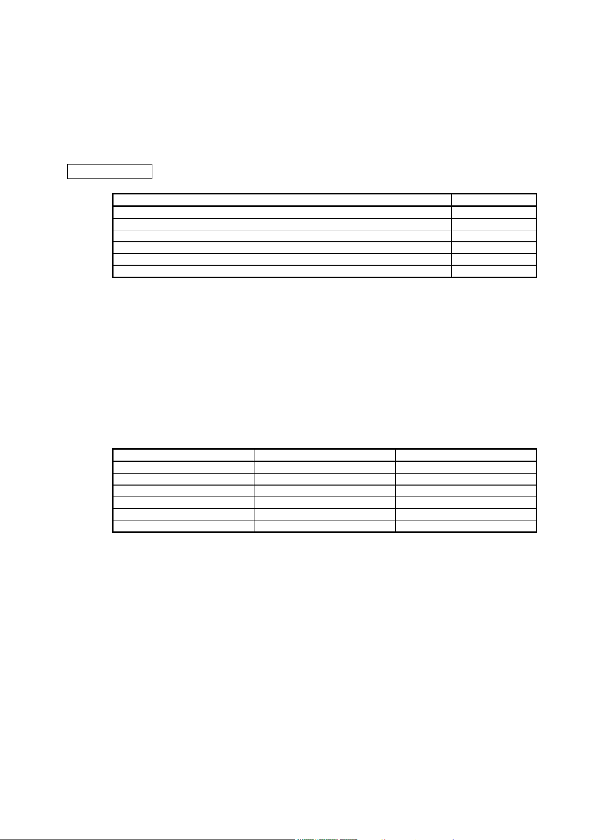
When you keep or use the equipment, please fulfill the following environment.
Item Environment
Ambient
temperature
Storage -20 °C to 65 °C (non-freezing)
Ambient
humidity
Storage
Ambience Indoors (no direct sunlight), free from corrosive gas, flammable gas, oil mist, dust, and dirt
Altitude Max. 1000 m above sea level
Vibration resistance 5.9 m/s2 at 10 Hz to 55 Hz (directions of X, Y, and Z axes)
Do not block the intake and exhaust areas of the servo amplifier. Otherwise, it may cause a malfunction.
Do not drop or strike the servo amplifier and servo motor. Isolate them from all impact loads.
When the equipment has been stored for an extended period of time, contact your local sales office.
When handling the servo amplifier, be careful about the edged parts such as corners of the servo
amplifier.
The servo amplifier must be installed in the metal cabinet.
When fumigants that contain halogen materials such as fluorine, chlorine, bromine, and iodine are used
for disinfecting and protecting wooden packaging from insects, they cause malfunction when entering our
products. Please take necessary precautions to ensure that remaining materials from fumigant do not
enter our products, or treat packaging with methods other than fumigation (heat method). Additionally,
disinfect and protect wood from insects before packing products.
Operation 0 °C to 55 °C (non-freezing)
Operation
90% RH or less (non-condensing)
(2) Wiring
CAUTION
Wire the equipment correctly and securely. Otherwise, the servo motor may operate unexpectedly.
Do not install a power capacitor, surge killer, or radio noise filter (FR-BIF option) on the servo amplifier
output side.
To avoid a malfunction, connect the wires to the correct phase terminals (U, V, and W) of the servo
amplifier and servo motor.
A - 3
CAUTION
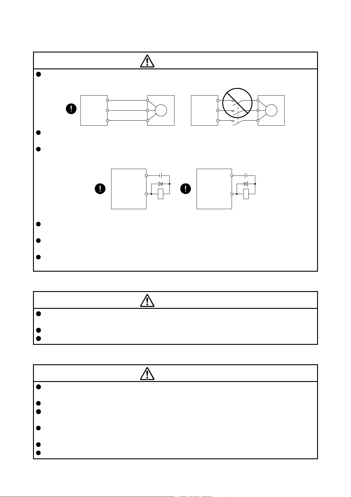
Connect the servo amplifier power output (U, V, and W) to the servo motor power input (U, V, and W)
directly. Do not let a magnetic contactor, etc. intervene. Otherwise, it may cause a malfunction.
Servo amplifier
U
V
W
The connection diagrams in this instruction manual are shown for sink interfaces, unless stated
otherwise.
The surge absorbing diode installed to the DC relay for control output should be fitted in the specified
direction. Otherwise, the emergency stop and other protective circuits may not operate.
Servo amplifier
DOCOM
Servo motor
U
V
W
24 V DC
Servo motorServo amplifier
24 V DC
U
V
W
M
U
M
V
W
Servo amplifier
DOCOM
Control output
signal
For sink output interface
RA
Control output
signal
For source output interface
RA
When the cable is not tightened enough to the terminal block, the cable or terminal block may generate
heat because of the poor contact. Be sure to tighten the cable with specified torque.
Connecting an encoder for different axis to the CN2A, CN2B, or CN2C connector may cause a
malfunction.
Connecting a servo motor for different axis to the CNP3A, CNP3B, or CN3C connector may cause a
malfunction.
(3) Test run and adjustment
CAUTION
Before operation, check the parameter settings. Improper settings may cause some machines to perform
unexpected operation.
Never adjust or change the parameter values extremely as it will make operation unstable.
Do not close to moving parts at servo-on status.
(4) Usage
CAUTION
Provide an external emergency stop circuit to ensure that operation can be stopped and power switched
off immediately.
Do not disassemble, repair, or modify the equipment.
Before resetting an alarm, make sure that the run signal of the servo amplifier is off in order to prevent a
sudden restart. Otherwise, it may cause an accident.
Use a noise filter, etc. to minimize the influence of electromagnetic interference. Electromagnetic
interference may be given to the electronic equipment used near the servo amplifier.
Burning or breaking a servo amplifier may cause a toxic gas. Do not burn or break it.
Use the servo amplifier with the specified servo motor.
A - 4
CAUTION
The electromagnetic brake on the servo motor is designed to hold the motor shaft and should not be
used for ordinary braking.
For such reasons as service life and mechanical structure (e.g. where a ball screw and the servo motor
are coupled via a timing belt), the electromagnetic brake may not hold the motor shaft. To ensure safety,
install a stopper on the machine side.
(5) Corrective actions
CAUTION
When it is assumed that a hazardous condition may occur due to a power failure or product malfunction,
use a servo motor with an electromagnetic brake or external brake to prevent the condition.
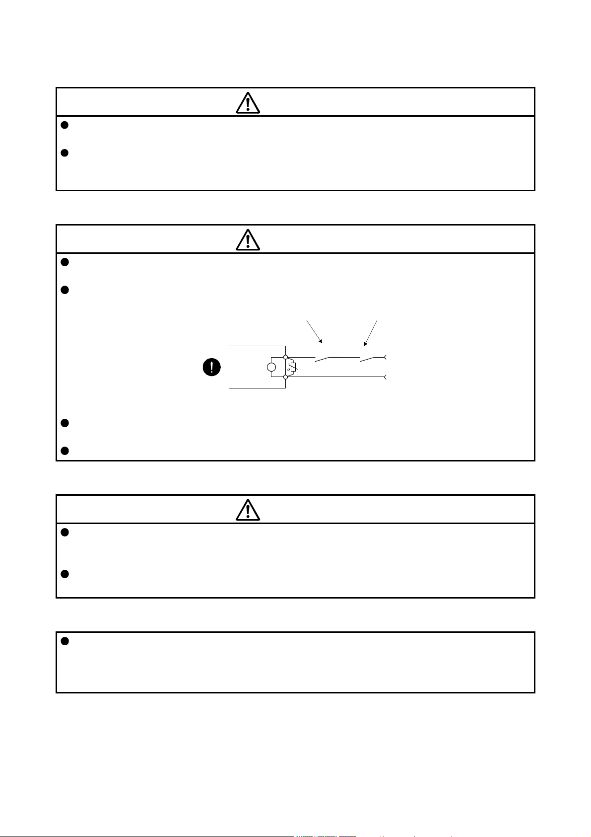
Configure an electromagnetic brake circuit so that it is activated also by an external EMG stop switch.
Contacts must be opened when CALM (AND
malfunction) or MBR (Electromagnetic brake
interlock) turns off.
Contacts must be opened
with the EMG stop switch.
Servo motor
B
Electromagnetic brake
When any alarm has occurred, eliminate its cause, ensure safety, and deactivate the alarm before
restarting operation.
Provide an adequate protection to prevent unexpected restart after an instantaneous power failure.
RA
24 V DC
(6) Maintenance, inspection and parts replacement
CAUTION
With age, the electrolytic capacitor of the servo amplifier will deteriorate. To prevent a secondary
accident due to a malfunction, it is recommend that the electrolytic capacitor be replaced every 10 years
when it is used in general environment. Please contact your local sales office.
When using a servo amplifier whose power has not been turned on for a long time, contact your local
sales office.
(7) General instruction
To illustrate details, the equipment in the diagrams of this Instruction Manual may have been drawn
without covers and safety guards. When the equipment is operated, the covers and safety guards must
be installed as specified. Operation must be performed in accordance with this Specifications and
Instruction Manual.
A - 5

DISPOSAL OF WASTE
Please dispose a servo amplifier, battery (primary battery) and other options according to your local laws and
regulations.
EEP-ROM life
The number of write times to the EEP-ROM, which stores parameter settings, etc., is limited to 100,000. If
the total number of the following operations exceeds 100,000, the servo amplifier may malfunction when the
EEP-ROM reaches the end of its useful life.
Write to the EEP-ROM due to parameter setting changes
Write to the EEP-ROM due to device changes
STO function of the servo amplifier
When using the STO function of the servo amplifier, refer to chapter 13.
For the MR-J3-D05 safety logic unit, refer to appendix 5.
Compliance with global standards
For the compliance with global standards, refer to appendix 4.
A - 6
<<About the manuals>>
You must have this Instruction Manual and the following manuals to use this servo. Ensure to prepare
them to use the servo safely.
When using an MR-J4W2-0303B6, refer to chapter 18.
Relevant manuals
Manual name Manual No.
MELSERVO-J4 SERVO AMPLIFIER INSTRUCTION MANUAL (TROUBLESHOOTING) SH(NA)030109
MELSERVO Servo Motor Instruction Manual (Vol. 3) (Note 1) SH(NA)030113
MELSERVO Linear Servo Motor Instruction Manual (Note 2) SH(NA)030110
MELSERVO Direct Drive Motor Instruction Manual (Note 3) SH(NA)030112
MELSERVO Linear Encoder Instruction Manual (Note 2, 4) SH(NA)030111
EMC Installation Guidelines IB(NA)67310
Note 1. It is necessary for using a rotary servo motor.
2. It is necessary for using a linear servo motor.
3. It is necessary for using a direct drive motor.
4. It is necessary for using a fully closed loop system.
<<Wiring>>
Wires mentioned in this Instruction Manual are selected based on the ambient temperature of 40 °C.
<<U.S. customary units>>
U.S. customary units are not shown in this manual. Convert the values if necessary according to the
following table.
Quantity SI (metric) unit U.S. customary unit
Mass 1 [kg] 2.2046 [lb]
Length 1 [mm] 0.03937 [inch]
Torque 1 [N•m] 141.6 [oz•inch]
Moment of inertia 1 [(× 10-4 kg•m2)] 5.4675 [oz•inch2]
Load (thrust load/axial load) 1 [N] 0.2248 [lbf]
Temperature N [°C] × 9/5 + 32 N [°F]
A - 7

MEMO
A - 8

CONTENTS
1. FUNCTIONS AND CONFIGURATION 1- 1 to 1-14
1.1 Summary ........................................................................................................................................... 1- 1
1.2 Function block diagram ..................................................................................................................... 1- 3
1.3 Servo amplifier standard specifications ............................................................................................ 1- 4
1.3.1 Integrated 2-axis servo amplifier ................................................................................................ 1- 4
1.3.2 Integrated 3-axis servo amplifier ................................................................................................ 1- 6
1.3.3 Combinations of servo amplifiers and servo motors .................................................................. 1- 8
1.4 Function list ....................................................................................................................................... 1- 9
1.5 Model designation ............................................................................................................................ 1-11
1.6 Parts identification ............................................................................................................................ 1-12
1.7 Configuration including auxiliary equipment .................................................................................... 1-13
2. INSTALLATION 2- 1 to 2- 6
2.1 Installation direction and clearances ................................................................................................ 2- 1
2.2 Keep out foreign materials ................................................................................................................ 2- 3
2.3 Encoder cable stress ........................................................................................................................ 2- 3
2.4 SSCNET III cable laying ................................................................................................................... 2- 3
2.5 Inspection items ................................................................................................................................ 2- 5
2.6 Parts having service lives ................................................................................................................. 2- 6
3. SIGNALS AND WIRING 3- 1 to 3-38
3.1 Input power supply circuit ................................................................................................................. 3- 2
3.2 I/O signal connection example .......................................................................................................... 3- 5
3.2.1 For sink I/O interface .................................................................................................................. 3- 5
3.2.2 For source I/O interface ............................................................................................................. 3- 7
3.3 Explanation of power supply system ................................................................................................ 3- 8
3.3.1 Signal explanations .................................................................................................................... 3- 8
3.3.2 Power-on sequence .................................................................................................................. 3-10
3.3.3 Wiring CNP1, CNP2, and CNP3 ............................................................................................... 3-11
3.4 Connectors and pin assignment ...................................................................................................... 3-13
3.5 Signal (device) explanations ............................................................................................................ 3-14
3.5.1 Input device ............................................................................................................................... 3-14
3.5.2 Output device ............................................................................................................................ 3-15
3.5.3 Output signal ............................................................................................................................. 3-18
3.5.4 Power supply ............................................................................................................................. 3-18
3.6 Forced stop deceleration function ................................................................................................... 3-19
3.6.1 Forced stop deceleration function ............................................................................................. 3-19
3.6.2 Base circuit shut-off delay time function ................................................................................... 3-21
3.6.3 Vertical axis freefall prevention function ................................................................................... 3-22
3.6.4 Residual risks of the forced stop function (EM2) ...................................................................... 3-22
3.7 Alarm occurrence timing chart ......................................................................................................... 3-23
3.7.1 When you use the forced stop deceleration function ................................................................ 3-23
3.7.2 When you do not use the forced stop deceleration function ..................................................... 3-25
3.8 Interfaces ......................................................................................................................................... 3-26
3.8.1 Internal connection diagram ...................................................................................................... 3-26
1

3.8.2 Detailed description of interfaces .............................................................................................. 3-27
3.8.3 Source I/O interfaces ................................................................................................................ 3-28
3.9 SSCNET III cable connection .......................................................................................................... 3-29
3.10 Servo motor with an electromagnetic brake .................................................................................. 3-31
3.10.1 Safety precautions .................................................................................................................. 3-31
3.10.2 Timing chart ............................................................................................................................ 3-33
3.11 Grounding ...................................................................................................................................... 3-38
4. STARTUP 4- 1 to 4-20
4.1 Switching power on for the first time ................................................................................................. 4- 2
4.1.1 Startup procedure ...................................................................................................................... 4- 2
4.1.2 Wiring check ............................................................................................................................... 4- 3
4.1.3 Surrounding environment ........................................................................................................... 4- 4
4.2 Startup .............................................................................................................................................. 4- 4
4.3 Switch setting and display of the servo amplifier .............................................................................. 4- 6
4.3.1 Switches ..................................................................................................................................... 4- 6
4.3.2 Scrolling display ........................................................................................................................ 4-11
4.3.3 Status display of an axis ........................................................................................................... 4-12
4.4 Test operation .................................................................................................................................. 4-14
4.5 Test operation mode ........................................................................................................................ 4-14
4.5.1 Test operation mode in MR Configurator2 ................................................................................ 4-15
4.5.2 Motor-less operation in controller .............................................................................................. 4-17
5. PARAMETERS 5- 1 to 5-54
5.1 Parameter list .................................................................................................................................... 5- 2
5.1.1 Basic setting parameters ([Pr. PA_ _ ]) ...................................................................................... 5- 3
5.1.2 Gain/filter setting parameters ([Pr. PB_ _ ]) ............................................................................... 5- 4
5.1.3 Extension setting parameters ([Pr. PC_ _ ]) .............................................................................. 5- 5
5.1.4 I/O setting parameters ([Pr. PD_ _ ]) ......................................................................................... 5- 7
5.1.5 Extension setting 2 parameters ([Pr. PE_ _ ]) ............................................................................ 5- 8
5.1.6 Extension setting 3 parameters ([Pr. PF_ _ ]) ........................................................................... 5-10
5.1.7 Linear servo motor/DD motor setting parameters ([Pr. PL_ _ ]) ............................................... 5-11
5.2 Detailed list of parameters ............................................................................................................... 5-13
5.2.1 Basic setting parameters ([Pr. PA_ _ ]) ..................................................................................... 5-13
5.2.2 Gain/filter setting parameters ([Pr. PB_ _ ]) .............................................................................. 5-23
5.2.3 Extension setting parameters ([Pr. PC_ _ ]) ............................................................................. 5-36
5.2.4 I/O setting parameters ([Pr. PD_ _ ]) ........................................................................................ 5-43
5.2.5 Extension setting 2 parameters ([Pr. PE_ _ ]) ........................................................................... 5-47
5.2.6 Extension setting 3 parameters ([Pr. PF_ _ ]) ........................................................................... 5-49
5.2.7 Linear servo motor/DD motor setting parameters ([Pr. PL_ _ ]) ............................................... 5-51
6. NORMAL GAIN ADJUSTMENT 6- 1 to 6-20
6.1 Different adjustment methods ........................................................................................................... 6- 1
6.1.1 Adjustment on a single servo amplifier ...................................................................................... 6- 1
6.1.2 Adjustment using MR Configurator2 .......................................................................................... 6- 2
6.2 One-touch tuning .............................................................................................................................. 6- 3
6.2.1 One-touch tuning flowchart ........................................................................................................ 6- 3
6.2.2 Display transition and operation procedure of one-touch tuning ............................................... 6- 4
2

6.2.3 Caution for one-touch tuning ...................................................................................................... 6- 9
6.3 Auto tuning ....................................................................................................................................... 6-10
6.3.1 Auto tuning mode ...................................................................................................................... 6-10
6.3.2 Auto tuning mode basis ............................................................................................................. 6-11
6.3.3 Adjustment procedure by auto tuning ....................................................................................... 6-12
6.3.4 Response level setting in auto tuning mode ............................................................................. 6-13
6.4 Manual mode ................................................................................................................................... 6-14
6.5 2 gain adjustment mode .................................................................................................................. 6-17
7. SPECIAL ADJUSTMENT FUNCTIONS 7- 1 to 7-32
7.1 Filter setting ...................................................................................................................................... 7- 1
7.1.1 Machine resonance suppression filter ....................................................................................... 7- 2
7.1.2 Adaptive filter II ........................................................................................................................... 7- 5
7.1.3 Shaft resonance suppression filter ............................................................................................. 7- 7
7.1.4 Low-pass filter ............................................................................................................................ 7- 8
7.1.5 Advanced vibration suppression control II ................................................................................. 7- 8
7.1.6 Command notch filter ................................................................................................................ 7-13
7.2 Gain switching function .................................................................................................................... 7-15
7.2.1 Applications ............................................................................................................................... 7-15
7.2.2 Function block diagram ............................................................................................................. 7-16
7.2.3 Parameter .................................................................................................................................. 7-17
7.2.4 Gain switching procedure ......................................................................................................... 7-20
7.3 Tough drive function ........................................................................................................................ 7-24
7.3.1 Vibration tough drive function.................................................................................................... 7-24
7.3.2 Instantaneous power failure tough drive function ..................................................................... 7-26
7.4 Compliance with SEMI-F47 standard .............................................................................................. 7-29
7.5 Model adaptive control disabled ...................................................................................................... 7-31
8. TROUBLESHOOTING 8- 1 to 8-12
8.1 Explanation for the lists ..................................................................................................................... 8- 1
8.2 Alarm list ........................................................................................................................................... 8- 2
8.3 Warning list ....................................................................................................................................... 8- 8
8.4 Troubleshooting at power on ........................................................................................................... 8-10
9. OUTLINE DRAWINGS 9- 1 to 9- 6
9.1 Servo amplifier .................................................................................................................................. 9- 1
9.2 Connector ......................................................................................................................................... 9- 4
10. CHARACTERISTICS 10- 1 to 10-10
10.1 Overload protection characteristics .............................................................................................. 10- 1
10.2 Power supply capacity and generated loss .................................................................................. 10- 2
10.3 Dynamic brake characteristics ...................................................................................................... 10- 5
10.3.1 Dynamic brake operation ....................................................................................................... 10- 6
10.3.2 Permissible load to motor inertia when the dynamic brake is used ....................................... 10- 8
10.4 Cable bending life ......................................................................................................................... 10- 9
10.5 Inrush currents at power-on of main circuit and control circuit ..................................................... 10- 9
3

11. OPTIONS AND AUXILIARY EQUIPMENT 11- 1 to 11-48
11.1 Cable/connector sets .................................................................................................................... 11- 1
11.1.1 Combinations of cable/connector sets ................................................................................... 11- 2
11.1.2 SSCNET III cable ................................................................................................................... 11- 5
11.1.3 Battery cable/junction battery cable ....................................................................................... 11- 7
11.1.4 MR-D05UDL3M-B STO cable ................................................................................................ 11- 8
11.2 Regenerative options .................................................................................................................... 11- 8
11.2.1 Combination and regenerative power .................................................................................... 11- 8
11.2.2 Selection of regenerative option ............................................................................................ 11- 9
11.2.3 Parameter setting .................................................................................................................. 11-11
11.2.4 Connection of regenerative option ........................................................................................ 11-12
11.2.5 Dimensions ........................................................................................................................... 11-13
11.3 Battery .......................................................................................................................................... 11-14
11.3.1 Selection of battery ............................................................................................................... 11-14
11.3.2 MR-BAT6V1SET-A battery ................................................................................................... 11-15
11.3.3 MR-BT6VCASE battery case ................................................................................................ 11-19
11.3.4 MR-BAT6V1 battery .............................................................................................................. 11-25
11.4 MR Configurator2 ........................................................................................................................ 11-26
11.4.1 Specifications ........................................................................................................................ 11-26
11.4.2 System configuration ............................................................................................................. 11-27
11.4.3 Precautions for using USB communication function ............................................................. 11-28
11.5 Selection example of wires .......................................................................................................... 11-29
11.6 Molded-case circuit breakers, fuses, magnetic contactors ......................................................... 11-31
11.7 Power factor improving AC reactors ............................................................................................ 11-33
11.8 Relays (recommended) ............................................................................................................... 11-34
11.9 Noise reduction techniques ......................................................................................................... 11-34
11.10 Earth-leakage current breaker ................................................................................................... 11-41
11.11 EMC filter (recommended) ................................................................................................
........ 11-44
11.12 Junction terminal block MR-TB26A ........................................................................................... 11-47
12. ABSOLUTE POSITION DETECTION SYSTEM 12- 1 to 12- 4
12.1 Summary ....................................................................................................................................... 12- 1
12.1.1 Features ................................................................................................................................. 12- 1
12.1.2 Structure ................................................................................................................................. 12- 1
12.1.3 Parameter setting ................................................................................................................... 12- 1
12.1.4 Confirmation of absolute position detection data ................................................................... 12- 2
12.2 Battery ........................................................................................................................................... 12- 2
12.2.1 Using MR-BAT6V1SET battery (only for MR-J4W2-0303B6) ............................................... 12- 2
12.2.2 Using MR-BT6VCASE battery case ....................................................................................... 12- 4
13. USING STO FUNCTION 13- 1 to 13-14
13.1 Introduction ................................................................................................................................... 13- 1
13.1.1 Summary ................................................................................................................................ 13- 1
13.1.2 Terms related to safety .......................................................................................................... 13- 1
13.1.3 Cautions ................................................................................................................................. 13- 1
13.1.4 Residual risks of the STO function ......................................................................................... 13- 2
13.1.5 Specifications ......................................................................................................................... 13- 3
13.1.6 Maintenance ........................................................................................................................... 13- 4
4

13.2 STO I/O signal connector (CN8) and signal layouts ..................................................................... 13- 4
13.2.1 Signal layouts ......................................................................................................................... 13- 4
13.2.2 Signal (device) explanations .................................................................................................. 13- 5
13.2.3 How to pull out the STO cable ............................................................................................... 13- 5
13.3 Connection example ..................................................................................................................... 13- 6
13.3.1 Connection example for CN8 connector ................................................................................ 13- 6
13.3.2 External I/O signal connection example using an MR-J3-D05 safety logic unit .................... 13- 7
13.3.3 External I/O signal connection example using an external safety relay unit ......................... 13- 9
13.3.4 External I/O signal connection example using a motion controller ....................................... 13-10
13.4 Detailed description of interfaces ................................................................................................ 13-11
13.4.1 Sink I/O interface ................................................................................................................... 13-11
13.4.2 Source I/O interface .............................................................................................................. 13-12
14. USING A LINEAR SERVO MOTOR 14- 1 to 14-32
14.1 Functions and configuration ......................................................................................................... 14- 1
14.1.1 Summary ................................................................................................................................ 14- 1
14.1.2 Servo system with auxiliary equipment .................................................................................. 14- 2
14.2 Signals and wiring ......................................................................................................................... 14- 3
14.3 Operation and functions ................................................................................................................ 14- 5
14.3.1 Startup .................................................................................................................................... 14- 5
14.3.2 Magnetic pole detection ......................................................................................................... 14- 8
14.3.3 Home position return ............................................................................................................. 14-16
14.3.4 Test operation mode in MR Configurator2 ............................................................................ 14-19
14.3.5 Operation from controller ...................................................................................................... 14-22
14.3.6 Function................................................................................................................................. 14-24
14.3.7 Absolute position detection system ....................................................................................... 14-26
14.4 Characteristics ............................................................................................................................. 14-27
14.4.1 Overload protection characteristics ...................................................................................... 14-27
14.4.2 Power supply capacity and generated loss .......................................................................... 14-28
14.4.3 Dynamic brake characteristics .............................................................................................. 14-30
14.4.4 Permissible load to motor mass ratio when the dynamic brake is used ............................... 14-31
15. USING A DIRECT DRIVE MOTOR 15- 1 to 15-20
15.1 Functions and configuration ......................................................................................................... 15- 1
15.1.1 Summary ................................................................................................................................ 15- 1
15.1.2 Servo system with auxiliary equipment .................................................................................. 15- 2
15.2 Signals and wiring ......................................................................................................................... 15- 3
15.3 Operation and functions ................................................................................................................ 15- 4
15.3.1 Startup procedure .................................................................................................................. 15- 5
15.3.2 Magnetic pole detection ......................................................................................................... 15- 6
15.3.3 Operation from controller ...................................................................................................... 15-14
15.3.4 Function................................................................................................................................. 15-15
15.4 Characteristics ............................................................................................................................. 15-17
15.4.1 Overload protection characteristics ...................................................................................... 15-17
15.4.2 Power supply capacity and generated loss .......................................................................... 15-18
15.4.3 Dynamic brake characteristics .............................................................................................. 15-19
5

16. FULLY CLOSED LOOP SYSTEM 16- 1 to 16-24
16.1 Functions and configuration ......................................................................................................... 16- 1
16.1.1 Function block diagram .......................................................................................................... 16- 1
16.1.2 Selecting procedure of control mode ..................................................................................... 16- 3
16.1.3 System configuration .............................................................................................................. 16- 4
16.2 Load-side encoder ........................................................................................................................ 16- 5
16.2.1 Linear encoder ....................................................................................................................... 16- 5
16.2.2 Rotary encoder ....................................................................................................................... 16- 5
16.2.3 Configuration diagram of encoder cable ................................................................................ 16- 5
16.2.4 MR-J4FCCBL03M branch cable ............................................................................................ 16- 6
16.3 Operation and functions ................................................................................................................ 16- 7
16.3.1 Startup .................................................................................................................................... 16- 7
16.3.2 Home position return ............................................................................................................. 16-14
16.3.3 Operation from controller ...................................................................................................... 16-17
16.3.4 Fully closed loop control error detection functions................................................................ 16-19
16.3.5 Auto tuning function .............................................................................................................. 16-20
16.3.6 Machine analyzer function .................................................................................................... 16-20
16.3.7 Test operation mode ............................................................................................................. 16-20
16.3.8 Absolute position detection system under fully closed loop system ..................................... 16-21
16.3.9 About MR Configurator2 ....................................................................................................... 16-22
17. APPLICATION OF FUNCTIONS 17- 1 to 17-58
17.1 J3 compatibility mode ................................................................................................................... 17- 1
17.1.1 Outline of J3 compatibility mode ............................................................................................ 17- 1
17.1.2 Operation modes supported by J3 compatibility mode .......................................................... 17- 2
17.1.3 J3 compatibility mode supported function list ........................................................................ 17- 2
17.1.4 How to switch J4 mode/J3 compatibility mode ...................................................................... 17- 5
17.1.5 How to use the J3 compatibility mode ................................................................................... 17- 6
17.1.6 Cautions for switching J4 mode/J3 compatibility mode ......................................................... 17- 7
17.1.7 Cautions for the J3 compatibility mode .................................................................................. 17- 7
17.1.8 Change of specifications of "J3 compatibility mode" switching process ................................ 17- 9
17.1.9 J3 extension function ............................................................................................................ 17-12
17.2 Scale measurement function ....................................................................................................... 17-53
17.2.1 Functions and configuration .................................................................................................. 17-53
17.2.2 Scale measurement encoder ................................................................................................ 17-55
17.2.3 How to use scale measurement function .............................................................................. 17-57
18. MR-J4W2-0303B6 SERVO AMPLIFIER 18- 1 to 18-54
18.1 Functions and configuration ......................................................................................................... 18- 1
18.1.1 Summary ................................................................................................................................ 18- 1
18.1.2 Function block diagram .......................................................................................................... 18- 2
18.1 3 Servo amplifier standard specifications ................................................................................. 18- 3
18.1.4 Combinations of servo amplifiers and servo motors .............................................................. 18- 4
18.1.5 Function list ............................................................................................................................ 18- 5
18.1.6 Model definition ...................................................................................................................... 18- 7
18.1.7 Parts identification .................................................................................................................. 18- 8
18.1.8 Configuration including peripheral equipment ....................................................................... 18- 9
18.2 Installation .................................................................................................................................... 18-10
6

18.2.1 Installation direction and clearances ..................................................................................... 18-11
18.2.2 Installation by DIN rail ........................................................................................................... 18-13
18.3 Signals and wiring ........................................................................................................................ 18-15
18.3.1 Input power supply circuit ..................................................................................................... 18-16
18.3.2 Explanation of power supply system ..................................................................................... 18-18
18.3.3 Selection of main circuit power supply/control circuit power supply ..................................... 18-22
18.3.4 Power-on sequence .............................................................................................................. 18-22
18.3.5 I/O Signal Connection Example ............................................................................................ 18-23
18.3.6 Connectors and pin assignment ........................................................................................... 18-26
18.3.7 Signal (device) explanations ................................................................................................. 18-27
18.3.8 Alarm occurrence timing chart .............................................................................................. 18-34
18.3.9 Interfaces .............................................................................................................................. 18-36
18.3.10 Grounding ........................................................................................................................... 18-39
18.4 Startup ......................................................................................................................................... 18-40
18.4.1 Startup procedure ................................................................................................................. 18-41
18.4.2 Troubleshooting when "24V ERROR" lamp turns on ............................................................ 18-42
18.4.3 Wiring check .......................................................................................................................... 18-42
18.4.4 Surrounding environment ...................................................................................................... 18-43
18.5 Switch setting and display of the servo amplifier ......................................................................... 18-44
18.6 Dimensions .................................................................................................................................. 18-45
18.7 Characteristics ............................................................................................................................. 18-46
18.7.1 Overload protection characteristics ...................................................................................... 18-46
18.7.2 Power supply capacity and generated loss .......................................................................... 18-47
18.7.3 Dynamic brake characteristics .............................................................................................. 18-47
18.7.4 Inrush currents at power-on of main circuit and control circuit ............................................. 18-49
18.8 Options and peripheral equipment .............................................................................................. 18-50
18.8.1 Cable/connector sets ............................................................................................................ 18-51
18.8.2 Combinations of cable/connector sets .................................................................................. 18-51
18.8.3 Selection example of wires ................................................................................................... 18-53
18.8.4 Circuit protector ..................................................................................................................... 18-54
APPENDIX App.- 1 to App.-47
App. 1 Auxiliary equipment manufacturer (for reference) ................................................................ App.- 1
App. 2 Handling of AC servo amplifier batteries for the United Nations Recommendations on the
Transport of Dangerous Goods ............................................................................................ App.- 1
App. 3 Symbol for the new EU Battery Directive .............................................................................. App.- 3
App. 4 Compliance with global standards ........................................................................................ App.- 4
App. 5 MR-J3-D05 Safety logic unit ................................................................................................ App.-19
App. 6 EC declaration of conformity ................................................................................................ App.-37
App. 7 How to replace servo amplifier without magnetic pole detection ......................................... App.-39
App. 8 Two-wire type encoder cable for HG-MR/HG-KR ................................................................ App.-40
App. 9 SSCNET III cable (SC-J3BUS_M-C) manufactured by Mitsubishi Electric System &
Service ................................................................................................................................. App.-42
App. 10 CNP_crimping connector ..................................................................................................... App.-42
App. 11 Recommended cable for servo amplifier power supply ....................................................... App.-43
App. 12 Amplifier without dynamic brake .......................................................................................... App.-45
App. 13 Driving on/off of main circuit power supply with DC power supply ...................................... App.-46
7

MEMO
8

1. FUNCTIONS AND CONFIGURATION
1. FUNCTIONS AND CONFIGURATION
POINT
In MELSERVO-J4 series, ultra-small capacity servo amplifiers compatible with
48 V DC and 24 V DC power supplies are available as MR-J4W2-0303B6. Refer
to chapter 18 for details of MR-J4W2-0303B6 servo amplifiers.
1.1 Summary
The MELSERVO-J4 series of multi-axis servo amplifiers inherits the high performance, sophisticated
functions, and usability of the MR-J4-B servo amplifiers, and ensures space saving, reduced wiring, and
energy saving.
The MR-J4W_-B servo amplifier is connected to controllers, including a servo system controller, on the fast
synchronization network, SSCNET III/H. The servo amplifier directly receives a command from a controller to
drive a servo motor.
One MR-J4W_-B servo amplifier can drive two or three servo motors. The footprint of one MR-J4W_-B servo
amplifier is considerably smaller than that of two or three MR-J4-B servo amplifiers. You can install MRJ4W_-B servo amplifiers without clearance between them. This makes your system more compact.
The multi-axis structure enables multiple axes to share the SSCNET III cable, control circuit power supply
cable, and main circuit power supply cable. This ensures reduced wiring.
For the MR-J4W_-B servo amplifier, the parameter settings allows you to use a rotary servo motor, linear
servo motor, and direct drive motor for each axis. The axes can be connected to a rotary servo motor, linear
servo motor, and direct drive motor, which have different capacity. Using a linear servo motor or direct drive
motor simplifies the system, and using the MR-J4W_-B servo amplifier downsizes the equipment, enhances
the equipment performance, and ensures space saving.
Using regenerative energy generated when a servo motor decelerates ensures energy saving.
Depending on the operating conditions, the regenerative option is not required.
As the MR-J4-B servo amplifier, the MR-J4W_-B servo amplifier supports the one-touch tuning and the realtime auto tuning. This enables you to easily adjust the servo gain according to the machine.
The tough drive function and the drive recorder function, which are well-received in the MELSERVO-JN
series, have been improved. The MR-J4W_-B servo amplifier supports the improved functions. Additionally,
the preventive maintenance support function detects an error in the machine parts. This function provides
strong support for the machine maintenance and inspection.
On the SSCNET III/H network, the stations are connected with a maximum distance of 100 m between them.
This allows you to create a large system.
The MR-J4W_-B servo amplifier supports the Safe Torque Off (STO) function. When the MR-J4W_-B servo
amplifier is connected to a SSCNET III/H-compatible servo system controller, in addition to the STO function,
the servo amplifier also supports the Safe Stop 1 (SS1), Safe Stop 2 (SS2), Safe Operating Stop (SOS),
Safely-Limited Speed (SLS), Safe Brake Control (SBC), and Safe Speed Monitor (SSM) functions.
The MR-J4W_-B servo amplifier has a USB communication interface. Therefore, you can connect the servo
amplifier to the personal computer with MR Configurator2 installed to perform the parameter setting, test
operation, gain adjustment, and others.
1 - 1
1. FUNCTIONS AND CONFIGURATION
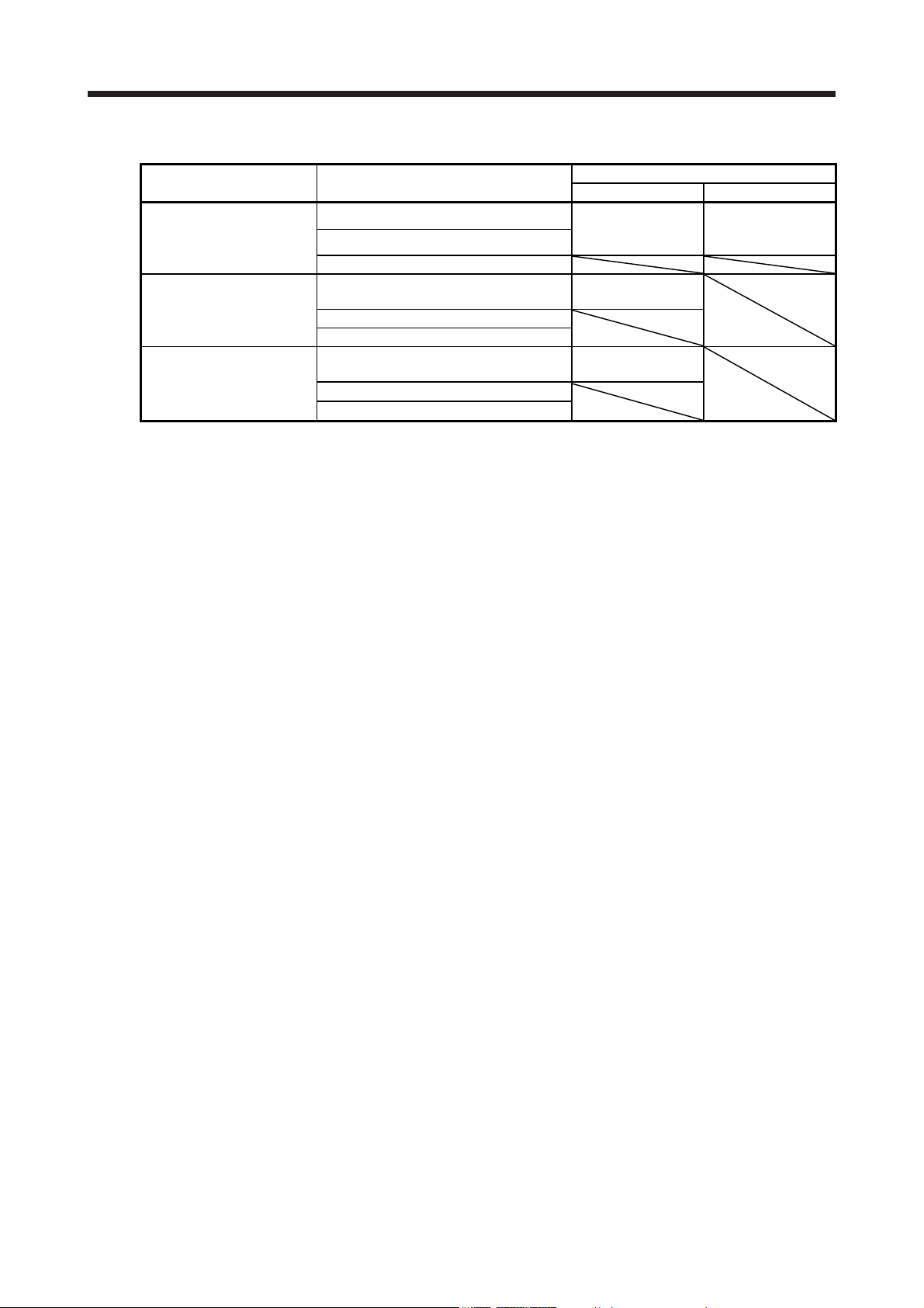
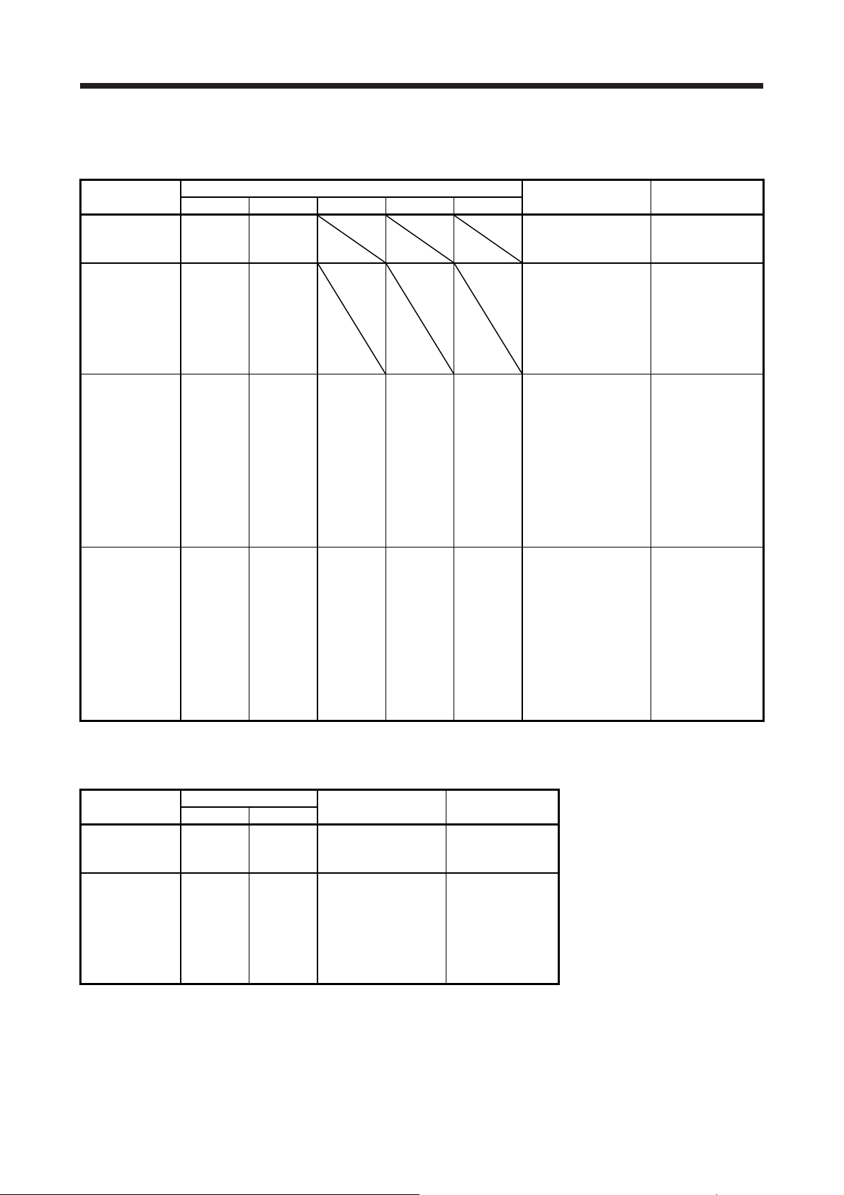
Table 1.1 Connectors to connect from external encoders
Operation mode External encoder communication method
Two-wire type
Linear servo motor system
A/B/Z-phase differential output method
Fully closed loop system
A/B/Z-phase differential output method
Scale measurement function
A/B/Z-phase differential output method
Note 1. The MR-J4THCBL03M branch cable is necessary.
2. The MR-J4FCCBL03M branch cable is necessary.
3. When the communication method of the servo motor encoder is four-wire type and A/B/Z-phase differential output
method, MR-J4W2-_B cannot be used. Use an MR-J4-_B-RJ.
4. This is used with servo amplifiers with software version A3 or later.
5. This is used with servo amplifiers with software version A8 or later.
6. The synchronous encoder Q171ENC-W8 cannot be used due to the four-wire type.
Four-wire type
Two-wire type
Four-wire type (Note 6)
Two-wire type
Four-wire type (Note 6)
Connector
MR-J4W2-_B MR-J4W3-_B
CN2A (Note 1)
CN2B (Note 1)
CN2A (Note 2, 3, 4)
CN2B (Note 2, 3, 4)
CN2A (Note 2, 3, 5)
CN2B (Note 2, 3, 5)
CN2A (Note 1)
CN2B (Note 1)
CN2C (Note 1)
1 - 2
1. FUNCTIONS AND CONFIGURATION
e
r
s
y
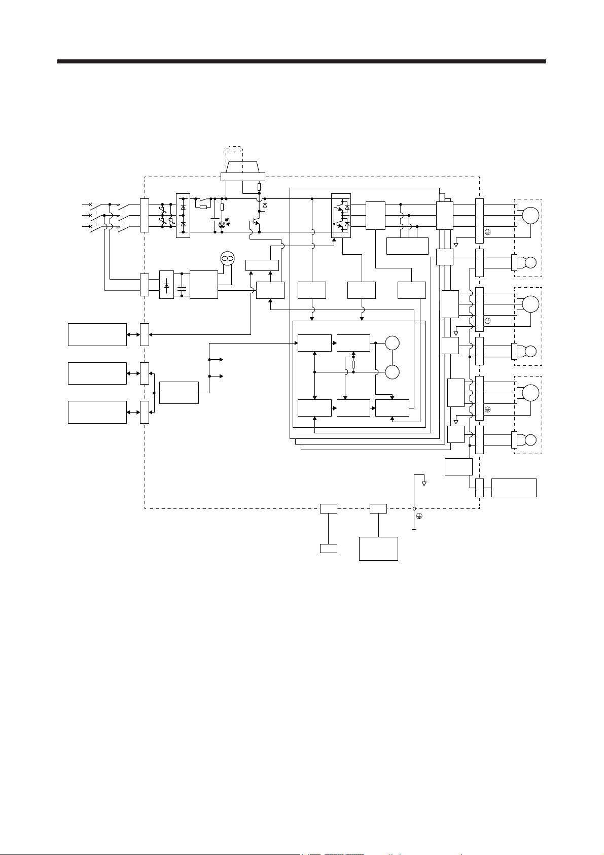
1.2 Function block diagram
The function block diagram of this servo is shown below.
Regenerativ
option
P+ C D
CNP2
Regenerative
+
TR
CHARGE
lamp
Control (B-axis)
Control (C-axis)
Built-in
regenerative
resistor
STO circuit
Base
amplifier
TRM (A)
Overvoltage
Control (A-axis)
Model position
control (A)
Actual position
control (A)
(Note 2)
Powe
uppl
MCCB MC
STO switch
Servo system
controller or
servo amplifier
Servo amplifier
or cap
L1
L2
CNP1
L3
L11
L21
CNP2
CN8CN1ACN1B
U
U U
Diode
stack
I/F
Control
Relay
Cooling fan
(Note 1)
Control
circuit
+
power
supply
Overcurrent
(A)
Model speed
control (A)
Actual speed
control (A)
Current
detector
brake circuit (A)
Virtual
motor
Virtual
encoder
Current
control (A)
Dynamic
Current
detection
(A)
A-axis
output
A-axis
F/B
B-axis
output
B-axis
F/B
C-axis
output
C-axis
A-axis Servo motor
U
V
W
CNP3ACN2ACNP3BCN2BCNP3CCN2C
B-axis Servo motor
U
V
W
C-axis Servo motor
U
V
W
F/B
M
E
M
E
M
E
Step-down
circuit
MR-BT6VCASE
CN4
Battery case +
CN5
USB
Personal
computer
CN3
Digital I/O
control
Battey
(for absolute position
detection system)
Note 1. The MR-J4W2-22B has no cooling fan.
2. For 1-phase 200 V AC to 240 V AC, connect the power supply to L1 and L3. Leave L2 open. For the power supply
specifications, refer to section 1.3.
1 - 3
1. FUNCTIONS AND CONFIGURATION
1.3 Servo amplifier standard specifications
1.3.1 Integrated 2-axis servo amplifier
Model MR-J4W2- 22B 44B 77B 1010B
Rated voltage 3-phase 170 V AC
Output
Main circuit
power supply
input
Voltage/Frequency 1-phase 200 V AC to 240 V AC, 50 Hz/60 Hz
Control circuit
power supply
input
Inrush current [A] Refer to section 10.5.
Interface
power supply
Control method Sine-wave PWM control, current control method
Capacitor
regeneration
Built-in regenerative resistance [W] 20 100
Dynamic brake Built-in
SSCNET III/H command
communication cycle (Note 9)
Communication function USB: Connect a personal computer (MR Configurator2 compatible)
Encoder output pulse Compatible (A/B-phase pulse)
Analog monitor None
Fully closed loop control Compatible (Note 8)
Scale measurement function Compatible (Note 10)
Load-side encoder interface Mitsubishi high-speed serial communication (Note 6)
Protective functions
Rated current
(each axis) [A]
Voltage/Frequency 3-phase or 1-phase 200 V AC to 240 V AC, 50 Hz/60 Hz
Rated current
(Note 11) [A]
Permissible voltage
fluctuation
Permissible
frequency fluctuation
Power supply
capacity
Inrush current [A] Refer to section 10.5.
Rated current [A] 0.4
Permissible voltage
fluctuation
Permissible
frequency fluctuation
Power consumption
Voltage 24 V DC ± 10%
Power supply
capacity
Reusable regenerative
energy (Note 2) [J]
Moment of inertia J
equivalent to the
permissible charging
amount (Note 3)
Mass
equivalent to
the
permissible
charging
amount
(Note 4) [kg]
[× 10
-4
[kVA]
[W]
kg • m2]
LM-H3 3.8 4.7 9.8
LM-K2
LM-U2
Overcurrent shut-off, regenerative overvoltage shut-off, overload shut-off (electronic thermal),
1.5 2.8 5.8 6.0
3-phase 200 V AC to
240 V AC, 50 Hz/60 Hz
2.9 5.2 7.5 9.8
3-phase or 1-phase 170 V AC to 264 V AC
Within ±5%
Refer to section 10.2.
1-phase 170 V AC to 264 V AC
Within ±5%
55
0.35 A (Note 1)
17 21 44
3.45 4.26 8.92
8.5 10.5 22.0
0.222 ms, 0.444 ms, 0.888 ms
servo motor overheat protection, encoder error protection, regenerative error protection,
undervoltage protection, instantaneous power failure protection, overspeed protection, and
error excessive protection
3-phase 170 V AC to
264 V AC
1 - 4
1. FUNCTIONS AND CONFIGURATION
Model MR-J4W2- 22B 44B 77B 1010B
Functional safety STO (IEC/EN 61800-5-2) (Note 7)
Standards certified by
CB
Response
performance
(Note 5) Test pulse
input (STO)
Safety
performance
Compliance
to standards
Structure (IP rating)
Close mounting Possible
Environment
Altitude Max. 1000 m above sea level
Vibration 5.9 m/s2 or less at 10 Hz to 55 Hz (directions of X, Y and Z axes)
Mass [kg] 1.5 2.0
Mean time to
dangerous failure
(MTTFd)
Diagnosis converge
(DC)
Average probability of
dangerous failures
per hour (PFH)
CE marking
UL standard UL 508C
Natural cooling, open
Ambient
temperature
Ambient
humidity
Ambience Indoors (no direct sunlight), free from corrosive gas, flammable gas, oil mist, dust, and dirt
Operation
Storage
Operation
Storage
Note 1. 0.35 A is the value applicable when all I/O signals are used. The current capacity can be decreased by reducing the number of
I/O points.
2. Reusable regenerative energy corresponds to energy generated under the following conditions.
Rotary servo motor: Regenerative energy is generated when the machine, whose moment of inertia is equivalent to the
permissible charging amount, decelerates from the rated speed to stop.
Linear servo motor: Regenerative energy is generated when the machine, whose mass is equivalent to the permissible
charging amount, decelerates from the maximum speed to stop.
Direct drive motor: Regenerative energy is generated when the machine, whose moment of inertia is equivalent to the
permissible charging amount, decelerates from the rated speed to stop.
3. Moment of inertia when the motor decelerates from the rated speed to stop
Moment of inertia for two axes when two motors decelerate simultaneously
Moment of inertia for each axis when multiple motors do not decelerate simultaneously
The values also apply to the direct drive motor.
4. Mass when the machine decelerates from the maximum speed to stop
The primary-side (coil) mass is included.
Mass for two axes when two motors decelerate simultaneously
Mass for each axis when multiple motors do not decelerate simultaneously
5. Test pulse is a signal which instantaneously turns off a signal to the servo amplifier at a constant period for external circuit to
self-diagnose.
6. The load-side encoder is compatible only with two-wire type communication method. Not compatible with pulse train interface
(A/B/Z-phase differential output type).
7. STO is common for all axes.
8. Fully closed loop control is compatible with the servo amplifiers with software version A3 or later.
Check the software version of the servo amplifier using MR Configurator2.
9. The command communication cycle depends on the controller specifications and the number of axes connected.
10. The scale measurement function is available for the MR-J4W2-_B servo amplifiers of software version A8 or later. Check the
software version of the servo amplifier using MR Configurator2.
11. This value is applicable when a 3-phase power supply is used.
EN ISO 13849-1 PL d (category 3), IEC 61508 SIL 2, EN 62061 SIL CL2
8 ms or less (STO input off → energy shut off)
(IP20)
0 °C to 55 °C (non-freezing)
-20 °C to 65 °C (non-freezing)
Test pulse interval: 1 Hz to 25 Hz
Test pulse off time: Up to 1 ms
100 years or longer
Medium (90% to 99%)
1.68 × 10
LVD: EN 61800-5-1
EMC: EN 61800-3
MD: EN ISO 13849-1, EN 61800-5-2, EN 62061
90% RH or less (non-condensing)
-10
[1/h]
Force cooling, open (IP20)
1 - 5
1. FUNCTIONS AND CONFIGURATION
1.3.2 Integrated 3-axis servo amplifier
Model MR-J4W3- 222B 444B
Rated voltage 3-phase 170 V AC
Output
Main circuit
power supply
input
Rated current [A] 0.4
Control circuit
power supply
input
Inrush current [A] Refer to section 10.5.
Interface
power supply
Control method Sine-wave PWM control, current control method
Capacitor
regeneration
Built-in regenerative resistance [W] 30 100
Dynamic brake Built-in
SSCNET III/H command
communication cycle (Note 7)
Communication function USB: Connect a personal computer (MR Configurator2 compatible)
Encoder output pulse Not compatible
Analog monitor None
Fully closed loop control Not compatible
Scale measurement function Not compatible
Protective functions
Rated current
(each axis) [A]
Power supply
/Frequency
Rated current
(Note 9) [A]
Permissible voltage
fluctuation
Permissible
frequency fluctuation
Power supply
capacity [kVA]
Inrush current [A] Refer to section 10.5.
Power supply
/Frequency
Permissible voltage
fluctuation
Permissible
frequency fluctuation
Power consumption
[W]
Voltage/Frequency 24 V DC ± 10%
Power supply
capacity
Reusable regenerative
energy (Note 2) [J]
Moment of inertia J
equivalent to the
permissible charging
amount (Note 3)
Mass
equivalent to
the
permissible
charging
amount
(Note 4) [kg]
-4
[× 10
kg • m2]
LM-H3 4.7 6.7
LM-K2
LM-U2
Overcurrent shut-off, regenerative overvoltage shut-off, overload shut-off (electronic thermal),
servo motor overheat protection, encoder error protection, regenerative error protection,
undervoltage protection, instantaneous power failure protection, overspeed protection, and
1.5 2.8
3-phase or 1-phase 200 V AC to 240 V AC, 50 Hz/60 Hz
4.3 7.8
3-phase or 1-phase 170 V AC to 264 V AC, 50 Hz/60 Hz
Within ±5%
Refer to section 10.2.
1-phase 200 V AC to 240 V AC, 50 Hz/60 Hz
1-phase 170 V AC to 264 V AC
Within ±5%
55
0.45 A (Note 1)
21 30
4.26 6.08
10.5 15.0
0.222 ms (Note 8), 0.444 ms, 0.888 ms
error excessive protection
1 - 6
1. FUNCTIONS AND CONFIGURATION
Model MR-J4W3- 222B 444B
Functional safety STO (IEC/EN 61800-5-2) (Note 6)
Standards certified by
CB
Response
performance
(Note 5) Test pulse
input (STO)
Safety
performance
Compliance
to standards
Structure (IP rating) Force cooling, open (IP20)
Close mounting Possible
Environment
Altitude Max. 1000 m above sea level
Vibration 5.9 m/s2 or less at 10 Hz to 55 Hz (directions of X, Y and Z axes)
Mass [kg] 1.9
Mean time to
dangerous failure
(MTTFd)
Diagnosis converge
(DC)
Average probability of
dangerous failures
per hour (PFH)
CE marking
UL standard UL 508C
Ambient
temperature
Ambient
humidity
Ambience Indoors (no direct sunlight), free from corrosive gas, flammable gas, oil mist, dust, and dirt
Operation
Storage
Operation
Storage
Note 1. 0.45 A is the value applicable when all I/O signals are used. The current capacity can be decreased by reducing the number of
I/O points.
2. Reusable regenerative energy corresponds to energy generated under the following conditions.
Rotary servo motor: Regenerative energy is generated when the machine, whose moment of inertia is equivalent to the
permissible charging amount, decelerates from the rated speed to stop.
Linear servo motor: Regenerative energy is generated when the machine, whose mass is equivalent to the permissible
charging amount, decelerates from the maximum speed to stop.
Direct drive motor: Regenerative energy is generated when the machine, whose moment of inertia is equivalent to the
permissible charging amount, decelerates from the rated speed to stop.
3. Moment of inertia when the machine decelerates from the rated speed to stop
Moment of inertia for three axes when three motors decelerate simultaneously
Moment of inertia for each axis when multiple motors do not decelerate simultaneously
The values also apply to the direct drive motor.
4. Mass when the machine decelerates from the maximum speed to stop
The primary-side (coil) mass is included.
Mass for three axes when three motors decelerate simultaneously
Mass for each axis when multiple motors do not decelerate simultaneously
5. Test pulse is a signal which instantaneously turns off a signal to the servo amplifier at a constant period for external circuit to
self-diagnose.
6. STO is common for all axes.
7. The command communication cycle depends on the controller specifications and the number of axes connected.
8. Servo amplifier with software version A3 or later is compatible with the command communication cycle of 0.222 ms. However,
note that the following functions are not available when 0.222 ms is used: auto tuning (real time, one-touch, and vibration
suppression control), adaptive filter II, vibration tough drive, and power monitoring.
9. This value is applicable when a 3-phase power supply is used.
EN ISO 13849-1 PL d (category 3), IEC 61508 SIL 2, EN 62061 SIL CL2
8 ms or less (STO input off → energy shut off)
Test pulse interval: 1 Hz to 25 Hz
Test pulse off time: Up to 1 ms
100 years or longer
Medium (90% to 99%)
1.68 × 10
LVD: EN 61800-5-1
EMC: EN 61800-3
MD: EN ISO 13849-1, EN 61800-5-2, EN 62061
0 °C to 55 °C (non-freezing)
-20 °C to 65 °C (non-freezing)
90% RH or less (non-condensing)
-10
[1/h]
1 - 7
1. FUNCTIONS AND CONFIGURATION
1.3.3 Combinations of servo amplifiers and servo motors
(1) MR-J4W2-_B servo amplifier
Servo amplifier
MR-J4W2-22B 053
MR-J4W2-44B
MR-J4W2-77B
MR-J4W2-1010B
HG-KR HG-MR HG-SR HG-UR HG-JR
13
23
053
13
23
43
43
73
43
73
Note. The combination is for increasing the maximum torque of HG-JR53 servo motor to 400%.
(2) MR-J4W3-_B servo amplifier
Servo amplifier
MR-J4W3-222B 053
MR-J4W3-444B
Rotary servo motor
HG-KR HG-MR
13
23
053
13
23
43
Rotary servo motor
053
13
23
053
13
23
43
43
73
43
73
053
13
23
053
13
23
43
LM-U2PAB-05M-0SS0
LM-U2PBB-07M-1SS0
LM-H3P2A-07P-BSS0
LM-H3P3A-12P-CSS0
LM-K2P1A-01M-2SS1
LM-U2PAB-05M-0SS0
LM-U2PAD-10M-0SS0
LM-U2PAF-15M-0SS0
LM-U2PBB-07M-1SS0
51
52
51
81
52
102
Linear servo motor
(primary side)
72
72
53
73
53 (Note)
73
103
Direct drive motor
TM-RFM002C20
TM-RFM002C20
TM-RFM004C20
Linear servo motor
LM-U2PAB-05M-0SS0
LM-U2PBB-07M-1SS0
LM-H3P2A-07P-BSS0
LM-H3P3A-12P-CSS0
LM-K2P1A-01M-2SS1
LM-U2PAB-05M-0SS0
LM-U2PAD-10M-0SS0
LM-U2PAF-15M-0SS0
LM-U2PBB-07M-1SS0
LM-H3P2A-07P-BSS0
LM-H3P3A-12P-CSS0
LM-H3P3B-24P-CSS0
LM-H3P3C-36P-CSS0
LM-H3P7A-24P-ASS0
LM-K2P1A-01M-2SS1
LM-K2P2A-02M-1SS1
LM-U2PAD-10M-0SS0
LM-U2PAF-15M-0SS0
LM-U2PBD-15M-1SS0
LM-U2PBF-22M-1SS0
LM-H3P2A-07P-BSS0
LM-H3P3A-12P-CSS0
LM-H3P3B-24P-CSS0
LM-H3P3C-36P-CSS0
LM-H3P7A-24P-ASS0
LM-K2P1A-01M-2SS1
LM-K2P2A-02M-1SS1
LM-U2PAD-10M-0SS0
LM-U2PAF-15M-0SS0
LM-U2PBD-15M-1SS0
LM-U2PBF-22M-1SS0
(primary side)
Direct drive motor
TM-RFM002C20
TM-RFM002C20
TM-RFM004C20
TM-RFM004C20
TM-RFM006C20
TM-RFM006E20
TM-RFM012E20
TM-RFM012G20
TM-RFM040J10
TM-RFM004C20
TM-RFM006C20
TM-RFM006E20
TM-RFM012E20
TM-RFM018E20
TM-RFM012G20
TM-RFM040J10
1 - 8

1. FUNCTIONS AND CONFIGURATION
1.4 Function list
The following table lists the functions of this servo. For details of the functions, refer to the reference field.
Function Description
This realizes a high response and stable control following the ideal model. The
two-degrees-of-freedom-model model adaptive control enables you to set a
Model adaptive control
Position control mode This servo amplifier is used as a position control servo.
Speed control mode This servo amplifier is used as a speed control servo.
Torque control mode This servo amplifier is used as a torque control servo.
High-resolution encoder
Absolute position detection
system
Gain switching function
Advanced vibration
suppression control II
Machine resonance
suppression filter
Shaft resonance suppression
filter
Adaptive filter II
Low-pass filter
Machine analyzer function
Robust filter
Slight vibration suppression
control
Auto tuning
Regenerative option
Alarm history clear Alarm history is cleared. [Pr. PC21]
Output signal selection
(Device settings)
Output signal (DO) forced
output
Test operation mode
MR Configurator2
Linear servo system
Direct drive servo system Direct drive servo system can be configured to drive a direct drive motor. Chapter 15
One-touch tuning
response to the command and response to the disturbance separately.
Additionally, this function can be disabled. Refer to section 7.5 for disabling this
function. This is used by servo amplifiers with software version B4 or later. Check
the software version using MR Configurator2.
High-resolution encoder of 4194304 pulses/rev is used as the encoder of the rotary
servo motor compatible with the MELSERVO-J4 series.
Merely setting a home position once makes home position return unnecessary at
every power-on.
Using an input device or gain switching conditions (including the servo motor
speed) switches gains.
This function suppresses vibration at the arm end or residual vibration of the
machine.
The machine resonance suppression filter is a filter function (notch filter) which
decreases the gain of the specific frequency to suppress the resonance of the
mechanical system.
When a load is mounted to the servo motor shaft, resonance by shaft torsion
during driving may generate a mechanical vibration at high frequency. The shaft
resonance suppression filter suppresses the vibration.
Servo amplifier detects mechanical resonance and sets filter characteristics
automatically to suppress mechanical vibration.
Suppresses high-frequency resonance which occurs as servo system response is
increased.
Analyzes the frequency characteristic of the mechanical system by simply
connecting an MR Configurator2 installed personal computer and servo amplifier.
MR Configurator2 is necessary for this function.
This function provides better disturbance response in case low response level that
load to motor inertia ratio is high for such as roll send axes.
Suppresses vibration of ±1 pulse produced at a servo motor stop.
Automatically adjusts the gain to optimum value if load applied to the servo motor
shaft varies.
Used when the built-in regenerative resistor of the servo amplifier does not have
sufficient regenerative capability for the regenerative power generated.
The pins that output the output devices, including ALM (Malfunction) and INP (Inposition), can be assigned to certain pins of the CN3 connectors.
Output signal can be forced on/off independently of the servo status.
Use this function for output signal wiring check and others.
Jog operation, positioning operation, motor-less operation, DO forced output, and
program operation
MR Configurator2 is necessary for this function.
Using a personal computer, you can perform the parameter setting, test operation,
monitoring, and others.
Linear servo system can be configured using a linear servo motor and liner
encoder.
One click on a certain button on MR Configurator2 adjusts the gains of the servo
amplifier.
MR Configurator2 is necessary for this function.
Detailed
explanation
Chapter 12
Section 7.2
Section 7.1.5
Section 7.1.1
Section 7.1.3
Section 7.1.2
Section 7.1.4
[Pr. PE41]
[Pr. PB24]
Chapter 6
Section 11.2
[Pr. PD07] to
[Pr. PD09]
Section 4.5.1 (1)
(d)
Section 4.5
Section 11.4
Chapter 14
Section 6.2
1 - 9

1. FUNCTIONS AND CONFIGURATION
y
Function Description
Enables to avoid triggering [AL. 10 Undervoltage] using the electrical energy
charged in the capacitor in case that an instantaneous power failure occurs during
SEMI-F47 function (Note)
Tough drive function
Drive recorder function
STO function
Servo amplifier life diagnosis
function
Power monitoring function
Machine diagnostic function
Fully closed loop system
Scale measurement function
J3 compatibility mode
Continuous operation to
torque control mode
Note. For servo system controllers which are available with this, contact your local sales office.
operation. Use a 3-phase for the input power supply of the servo amplifier. Using a
1-phase 200 V AC for the input power supply will not comply with the SEMI-F47
standard.
This function makes the equipment continue operating even under the condition
that an alarm occurs.
The tough drive function includes two types: the vibration tough drive and the
instantaneous power failure tough drive.
This function continuously monitors the servo status and records the status
transition before and after an alarm for a fixed period of time. You can check the
recorded data on the drive recorder window on MR Configurator2 by clicking the
"Graph" button.
However, the drive recorder will not operate on the following conditions.
1. You are using the graph function of MR Configurator2.
2. You are using the machine analyzer function.
3. [Pr. PF21] is set to "-1".
4. The controller is not connected (except the test operation mode).
5. An alarm related to the controller is occurring.
This function is a functional safet
create a safety system for the equipment easily.
You can check the cumulative energization time and the number of on/off times of
the inrush relay. Before the parts of the servo amplifier, including a capacitor and
relay, malfunction, this function is useful for finding out the time for their
replacement.
MR Configurator2 is necessary for this function.
This function calculates the power running and the regenerative power from the
data, including the speed and current, in the servo amplifier. MR Configurator2 can
display the data, including the power consumption. Since the servo amplifier sends
data to a servo system controller, you can analyze the data and display the data on
a display with the SSCNET III/H system.
From the data in the servo amplifier, this function estimates the friction and
vibrational component of the drive system in the equipment and recognizes an
error in the machine parts, including a ball screw and bearing.
MR Configurator2 is necessary for this function.
Fully closed system can be configured using the load-side encoder. (not available
with the MR-J4 3-axis servo amplifiers)
This is used with servo amplifiers with software version A3 or later. Check the
software version using MR Configurator2.
The function transmits position information of a scale measurement encoder to the
controller by connecting the scale measurement encoder in semi closed loop
control.
Used by servo amplifiers with software version A8 or above. (not available with the
MR-J4 3-axis servo amplifiers)
This amplifier has "J3 compatibility mode" which compatible with the previous MRJ3-B series. Refer to section 17.1 for software versions.
This enables to smoothly switch the mode from position control mode/speed
control mode to torque control mode without stopping. This also enables to
decrease load to the machine and high quality molding without rapid changes in
speed or torque. For details of the continuous operation to torque control mode,
refer to the manuals for servo system controllers.
that complies with IEC/EN 61800-5-2. You can
Detailed
explanation
[Pr. PA20]
[Pr. PE25]
Section 7.4
Section 7.3
[Pr. PA23]
Chapter 13
Chapter 16
Section 17.2
Section 17.1
[Pr. PB03]
Servo system
controller
manuals
1 - 10
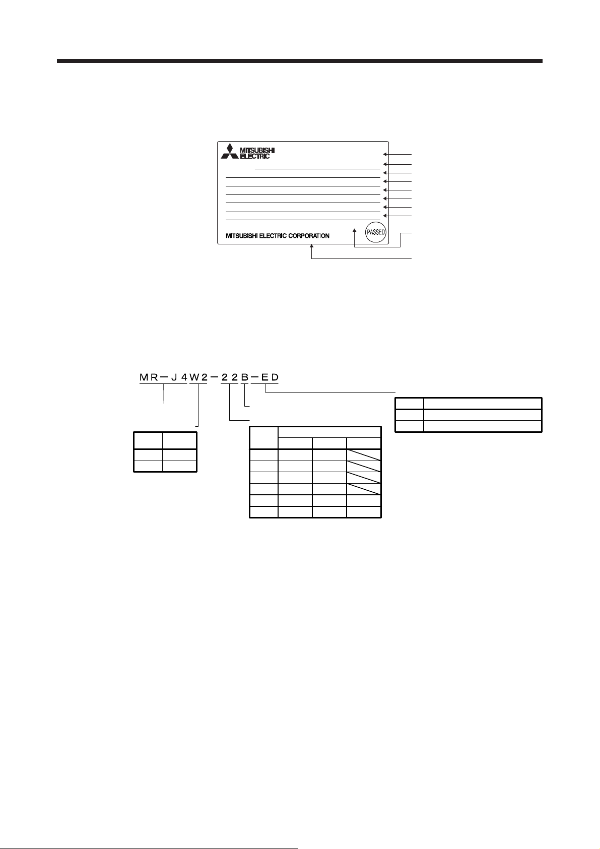
1. FUNCTIONS AND CONFIGURATION
1.5 Model designation
(1) Rating plate
The following shows an example of rating prate for explanation of each item.
AC SERVO
SER.A45001001
MODEL
POWER: 200W×3 (A, B, C)
INPUT: 3AC/AC200-240V 4.3A/7.5A 50/60Hz
OUTPUT: 3PH170V 0-360Hz 1.5A×3 (A, B, C)
STD.: IEC/EN 61800-5-1 MAN.: IB(NA)0300175
Max. Surrounding Air Temp.: 55℃
IP20 (Except for fan finger guard)
TOKYO 100-8310, JAPAN MADE IN JAPAN
Note. Production year and month of the servo amplifier are indicated in a serial number on
MR-J4W3-222B
KCC-REI-MEK-TC300A612G51
the rating plate.
The year and month of manufacture are indicated by the last one digit of the year and
1 to 9, X (10), Y (11), Z (12).
For September 2011, the Serial No. is like, "SERIAL: _ 19 _ _ _ _ _ _".
DATE: 2014-05
(2) Model
The following describes what each block of a model name indicates. Not all combinations of the symbols
are available.
Serial number
Model
Capacity
Applicable power supply
Rated output current
Standard, Manual number
Ambient temperature
IP rating
KC certification number, the year
and month of manufacture
Country of origin
Special specifications
Series
Number of axes
Number
Symbol
W2
W3
of axes
2
3
SSCNETIII/H interface
Rated output
Symbol
22
44
77
1010
222
444
Rated output [kW]
A-axis B-axis C-axis
0.2
0.4
0.75
1
0.2
0.4
0.2
0.4
0.75
1
0.2
0.4
0.2
0.4
Symbol Special specifications
None
-ED
Without a dynamic brake (Note)
Note. Refer to App. 12 for details.
Standard
1 - 11
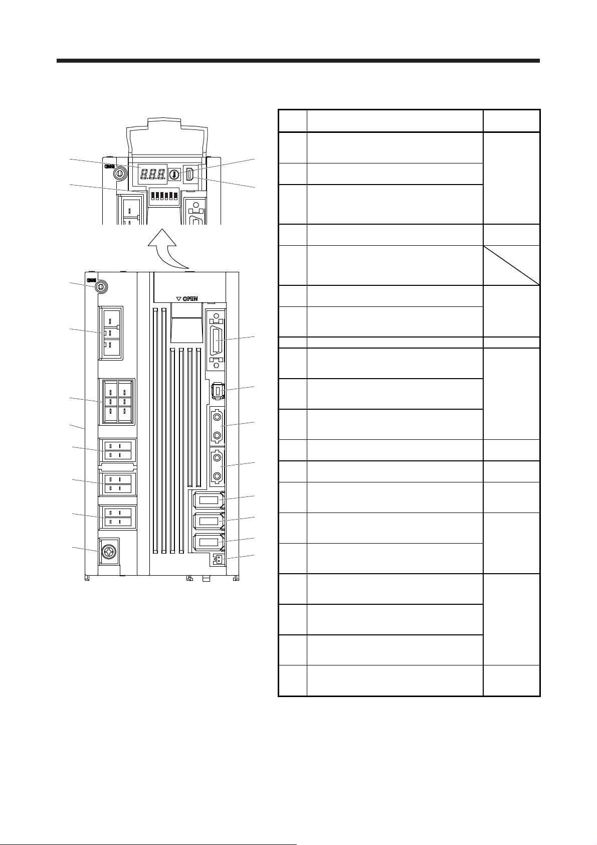
1. FUNCTIONS AND CONFIGURATION
1.6 Parts identification
(1)
(3)
(5)
(6)
(7)
(8)
(9)
(10)
(11)
(12)
Side
view
ON
123456
No. Name/Application
Display
(1)
The 3-digit, seven-segment LED shows the
(2)
(4)
(13)
(14)
(15)
(16)
(17)
(18)
(19)
(20)
Note 1. This figure shows the MR-J4 3-axis servo amplifier.
2. "External encoder" is a term for linear encoder used in the linear
servo status and the alarm number.
Axis selection rotary switch (SW1)
(2)
Used to set the axis No. of servo amplifier.
Control axis setting switch (SW2)
The test operation switch, the control axis
(3)
deactivation setting switch, and the auxiliary
axis number setting switch are available.
USB communication connector (CN5)
(4)
Connect with the personal computer.
Charge lamp
Lit to indicate that the main circuit is charged.
(5)
While this lamp is lit, do not reconnect the
cables.
Main circuit power supply connector (CNP1)
(6)
Connect the input power supply.
Control circuit power supply connector (CNP2)
(7)
Connect the control circuit power supply or
regenerative option.
(8) Rating plate Section 1.5
A-axis servo motor power supply connector
(CNP3A)
(9)
Connect the A-axis servo motor.
B-axis servo motor power supply connector
(CNP3B)
(10)
Connect the B-axis servo motor.
C-axis servo motor power supply connector
(CNP3C) (Note 1)
(11)
Connect the C-axis servo motor.
Protective earth (PE) terminal
(12)
Grounding terminal
I/O signal connector (CN3)
(13)
Used to connect digital I/O signals.
STO input signal connector (CN8)
(14)
Used to connect MR-J3-D05 safety logic unit
and external safety relay.
SSCNET III cable connector (CN1A)
(15)
Used to connect the servo system controller or
the previous axis servo amplifier.
SSCNET III cable connector (CN1B)
(16)
Used to connect the next axis servo amplifier.
For the final axis, put a cap.
A-axis encoder connector (CN2A)
(17)
(Note
Used to connect the A-axis servo motor
2)
encoder or external encoder.
B-axis encoder connector (CN2B)
(18)
(Note
Used to connect the B-axis servo motor
2)
encoder or external encoder.
C-axis encoder connector (CN2C) (Note 1)
(19)
(Note
Used to connect the C-axis servo motor
2)
encoder or linear encoder.
Battery connector (CN4)
(20)
Used to connect the battery unit for absolute
position data backup.
servo system, load-side encoder used in the fully closed loop
system, and scale measurement encoder used with the scale
measurement function in this manual.
Detailed
explanation
Section 4.3
Section 11.4
Section 3.1
Section 3.3
Section 3.1
Section 3.3
Section 3.11
Section 3.2
Section 3.4
Chapter 13
Section 3.2
Section 3.4
Section 3.1
Section 3.3
Section 11.3
Chapter 12
1 - 12
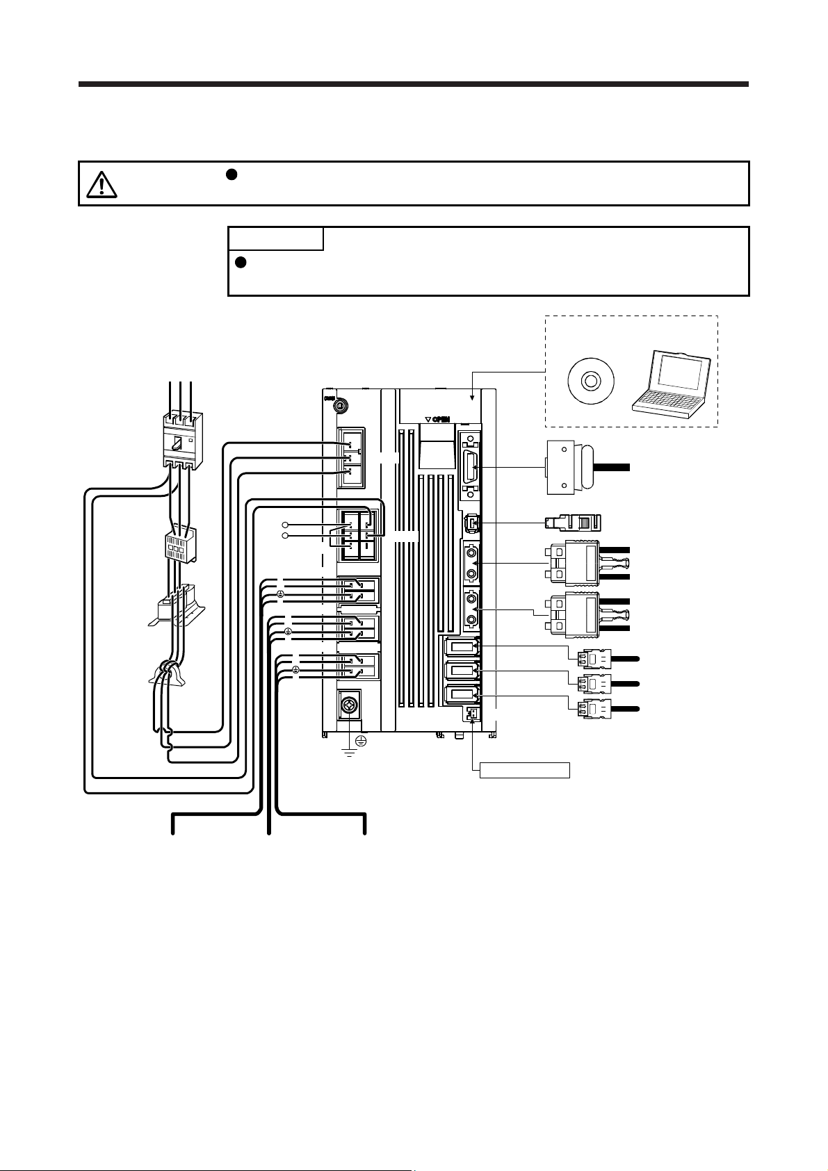
1. FUNCTIONS AND CONFIGURATION
A
1.7 Configuration including auxiliary equipment
CAUTION
Power supply
RS T
Connecting a servo motor for different axis to the CNP3A, CNP3B, or CNP3C
connector may cause a malfunction.
POINT
Equipment other than the servo amplifier and servo motor are optional or
recommended products.
CN5
(under the cover)
MR Configurator2
Personal
computer
Molded-case
circuit breaker
(MCCB) or fuse
Magnetic
contactor
(MC)
Power factor
improving
reactor
(FR-HAL)
Line noise
filter
(FR-BSF01)
L21
L11
L1
L2
L3
P+
C
D (Note 3)
Regenerative
option
CNP3A
U
W
V
CNP3B
U
W
V
CNP3C (Note 1)
U
W
V
CNP1
CNP2
CN3
CN8
CN1A
CN1B
CN2A
CN2B
CN2C (Note 1)
CN4
Battery unit
(Note 2)
I/O signal
Safety relay or
MR-J3-D05 safety logic unit
Servo system
controller or Front axis
servo amplifier CN1B
Rear servo amplifier
CN1A or Cap
A-axis encoder
B-axis encoder
C-axis encoder
A-axis
servo motor
Note 1. For the MR-J4 3-axis servo amplifier
2. The battery unit consists of an MR-BT6VCASE battery case and five MR-BAT6V1 batteries. The battery unit is used in the
absolute position detection system. (Refer to chapter 12.)
3.
lways connect P+ and D. When using the regenerative option, refer to section 11.2.
B-axis
servo motor
C-axis
servo motor
1 - 13
 Loading...