

Mitsubishi MR-J4-10GF, MR-J4-100GF, MR-J4-70GF, MR-J4-20GF, MR-J4-200GF Instruction Manual
...
General-Purpose AC Servo
CC-Link IE Field Network Interface
Servo Amplifier Instruction Manual
(Motion Mode)
-MR-J4-_GF_
-MR-J4-_GF_-RJ

SAFETY PRECAUTIONS
WARNING
Indicates that incorrect handling may cause hazardous conditions, resulting in
death or severe injury.
CAUTION
Indicates that incorrect handling may cause hazardous conditions, resulting in
minor or moderate injury or property damage.
Indicates what must not be done. For example, "No Fire" is indicated by .
Indicates what must be done. For example, grounding is indicated by .
(Please read the instructions carefully before using the equipment.)
To use the equipment correctly, do not attempt to install, operate, maintain, or inspect the equipment until you have read
through this Instruction Manual, Installation guide, and appended documents carefully. Do not use the equipment until you
have a full knowledge of the equipment, safety information and instructions.
In this Instruction Manual, the safety instruction levels are classified into "WARNING" and "CAUTION".
Note that the CAUTION level may lead to a serious consequence according to conditions.
Please follow the instructions of both levels because they are important to personnel safety.
What must not be done and what must be done are indicated by the following diagrammatic symbols.
In this Instruction Manual, instructions at a lower level than the above, instructions for other functions, and so on are classified
into "POINT".
After reading this Instruction Manual, keep it accessible to the operator.
1
[To prevent electric shock, note the following]
WARNING
● Before wiring and inspections, turn off the power and wait for 15 minutes or more until the charge
lamp turns off. Then, confirm that the voltage between P+ and N- is safe with a voltage tester and
others. Otherwise, an electric shock may occur. In addition, when confirming whether the charge lamp
is off or not, always confirm it from the front of the servo amplifier.
● Ground the servo amplifier and servo motor securely.
● Any person who is involved in wiring and inspection should be fully competent to do the work.
● Do not attempt to wire the servo amplifier and servo motor until they have been installed. Otherwise, it
may cause an electric shock.
● Do not operate switches with wet hands. Otherwise, it may cause an electric shock.
● The cables should not be damaged, stressed, loaded, or pinched. Otherwise, it may cause an electric
shock.
● During power-on or operation, do not open the front cover of the servo amplifier. Otherwise, it may
cause an electric shock.
● Do not operate the servo amplifier with the front cover removed. High-voltage terminals and charging
area are exposed and you may get an electric shock.
● Except for wiring and periodic inspection, do not remove the front cover of the servo amplifier even if
the power is off. The servo amplifier is charged and you may get an electric shock.
● To prevent an electric shock, always connect the protective earth (PE) terminal (marked ) of the
servo amplifier to the protective earth (PE) of the cabinet.
● To avoid an electric shock, insulate the connections of the power supply terminals.
[To prevent fire, note the following]
CAUTION
● Install the servo amplifier, servo motor, and regenerative resistor on incombustible material. Installing
them directly or close to combustibles will lead to smoke or a fire.
● Always connect a magnetic contactor between the power supply and the main circuit power supply
(L1/L2/L3) of the servo amplifier, in order to configure a circuit that shuts down the power supply on
the side of the servo amplifier’s power supply. If a magnetic contactor is not connected, continuous
flow of a large current may cause smoke or a fire when the servo amplifier malfunctions.
● Always connect a molded-case circuit breaker, or a fuse to each servo amplifier between the power
supply and the main circuit power supply (L1/L2/L3) of the servo amplifier, in order to configure a
circuit that shuts down the power supply on the side of the servo amplifier’s power supply. If a moldedcase circuit breaker or fuse is not connected, continuous flow of a large current may cause smoke or
a fire when the servo amplifier malfunctions.
● When using the regenerative resistor, switch power off with the alarm signal. Otherwise, a
regenerative transistor malfunction or the like may overheat the regenerative resistor, causing smoke
or a fire.
● Provide adequate protection to prevent screws and other conductive matter, oil and other combustible
matter from entering the servo amplifier and servo motor.
2

[To prevent injury, note the following]
CAUTION
● Only the power/signal specified in the Instruction Manual should be applied to each terminal.
Otherwise, it may cause an electric shock, fire, injury, etc.
● Connect cables to the correct terminals. Otherwise, a burst, damage, etc., may occur.
● Ensure that polarity (+/-) is correct. Otherwise, a burst, damage, etc., may occur.
● The servo amplifier heat sink, regenerative resistor, servo motor, etc., may be hot while the power is
on and for some time after power-off. Take safety measures such as providing covers to avoid
accidentally touching them by hands and parts such as cables.
3
[Additional instructions]
The following instructions should also be fully noted. Incorrect handling may cause a malfunction, injury, electric shock, fire,
etc.
[Transportation and installation]
CAUTION
● Transport the products correctly according to their mass.
● Stacking in excess of the specified number of product packages is not allowed.
● Do not hold the front cover, cables, or connectors when carrying the servo amplifier. Otherwise, it may
drop.
● Install the servo amplifier and the servo motor in a load-bearing place in accordance with the
Instruction Manual.
● Do not get on or put heavy load on the equipment. Otherwise, it may cause injury.
● The equipment must be installed in the specified direction.
● Maintain specified clearances between the servo amplifier and the inner surfaces of a control cabinet
or other equipment.
● Do not install or operate the servo amplifier and servo motor which have been damaged or have any
parts missing.
● Do not block the intake and exhaust areas of the servo amplifier. Otherwise, it may cause a
malfunction.
● Do not drop or apply heavy impact on the servo amplifiers and the servo motors. Otherwise, it may
cause injury, malfunction, etc.
● Do not strike the connector. Otherwise, it may cause a connection failure, malfunction, etc.
● When you keep or use the equipment, please fulfill the following environment.
Item Environment
Ambient
temperature
Ambient
humidity
Vibration resistance
Operation
Storage
Operation
Storage
Ambience
Altitude
Indoors (no direct sunlight), free from corrosive gas, flammable gas, oil mist, dust, and dirt
2000 m or less above sea level (Contact your local sales office for the altitude for options.)
0 °C to 55 °C (non-freezing)
-20 °C to 65 °C (non-freezing)
5 %RH to 90 %RH (non-condensing)
2
, at 10 Hz to 55 Hz (X, Y, Z axes)
5.9 m/s
● When the product has been stored for an extended period of time, contact your local sales office.
● When handling the servo motor, be careful with the sharp edges of the servo motor.
● The servo amplifier must be installed in a metal cabinet.
● When fumigants that contain halogen materials, such as fluorine, chlorine, bromine, and iodine, are
used for disinfecting and protecting wooden packaging from insects, they cause a malfunction when
entering our products. Please take necessary precautions to ensure that remaining materials from
fumigant do not enter our products, or treat packaging with methods other than fumigation, such as
heat treatment. Additionally, disinfect and protect wood from insects before packing the products.
● To prevent a fire or injury in case of an earthquake or other natural disasters, securely install, mount,
and wire the servo motor in accordance with the Instruction Manual.
4
[Wiring]
24 V DC
RA
DOCOM
Control output
signal
Servo amplifier
For sink output interface
24 V DC
RA
DOCOM
Control output
signal
Servo amplifier
For source output interface
CAUTION
● Wire the equipment correctly and securely. Otherwise, the servo motor may operate unexpectedly.
● Make sure to connect the cables and connectors by using the fixing screws and the locking
mechanism. Otherwise, the cables and connectors may be disconnected during operation.
● Do not install a power capacitor, surge killer, or radio noise filter (optional FR-BIF(-H)) on the servo
amplifier output side.
● To avoid a malfunction, connect the wires to the correct phase terminals (U/V/W) of the servo amplifier
and servo motor.
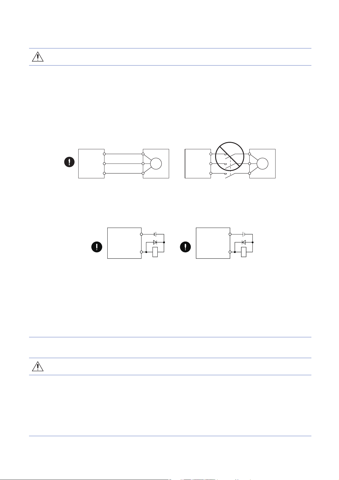
● Connect the servo amplifier power output (U/V/W) to the servo motor power input (U/V/W) directly. Do
not connect a magnetic contactor and others between them. Otherwise, it may cause a malfunction.
Servo amplifier
U
V
W
● The connection diagrams in this Instruction Manual are shown for sink interfaces, unless stated
otherwise.
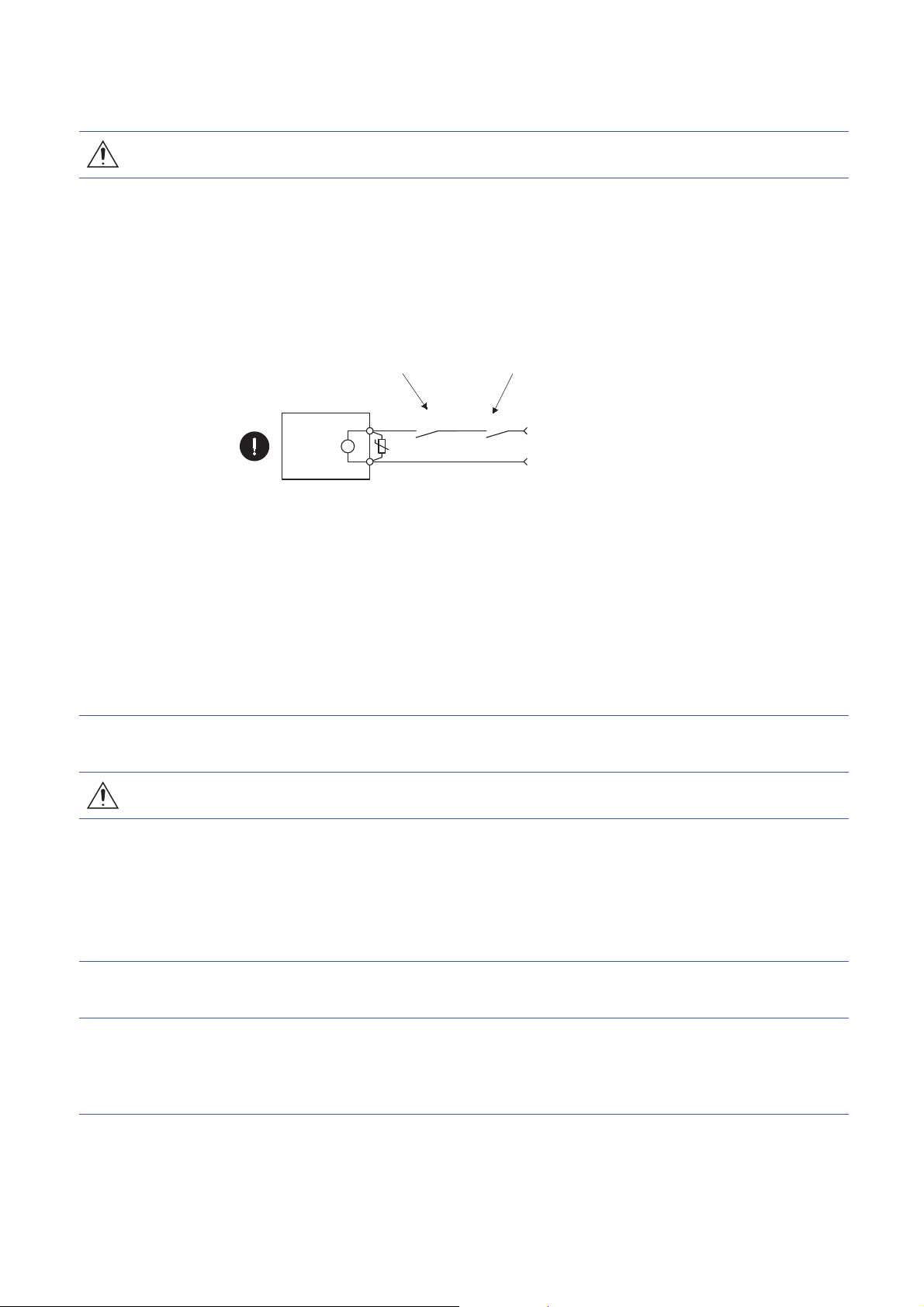
● The surge absorbing diode installed to the DC relay for control output should be fitted in the specified
direction. Otherwise, the converter unit and the drive unit will malfunction and will not output signals,
disabling the emergency stop and other protective circuits.
Servo motor
U
V
W
Servo motorServo amplifier
U
M
V
W
U
V
M
W
● When the wires are not tightened enough to the terminal block, the wires or terminal block may
generate heat because of the poor contact. Be sure to tighten the wires with specified torque.
● Connecting a servo motor of the wrong axis to U, V, W, or CN2 of the servo amplifier may cause a
malfunction.
● Configure a circuit to turn off EM2 or EM1 when the main circuit power supply is turned off to prevent
an unexpected restart of the servo amplifier.
● To prevent malfunction, avoid bundling power lines (input/output) and signal cables together or
running them in parallel to each other. Separate the power lines from the signal cables.
[Test run and adjustment]
CAUTION
● When executing a test run, follow the notice and procedures in this instruction manual. Otherwise, it
may cause a malfunction, damage to the machine, or injury.
● Before operation, check and adjust the parameter settings. Improper settings may cause some
machines to operate unexpectedly.
● Never make a drastic adjustment or change to the parameter values as doing so will make the
operation unstable.
● Do not get close to moving parts during the servo-on status.
5

[Usage]
CAUTION
● Provide an external emergency stop circuit to stop the operation and shut the power off immediately.
● For equipment in which the moving part of the machine may collide against the load side, install a limit
switch or stopper to the end of the moving part. The machine may be damaged due to a collision.
● Do not disassemble, repair, or modify the product. Otherwise, it may cause an electric shock, fire,
injury, etc. Disassembled, repaired, and/or modified products are not covered under warranty.
● Before resetting an alarm, make sure that the run signal of the servo amplifier is off in order to prevent
a sudden restart. Otherwise, it may cause an accident.
● Use a noise filter, etc., to minimize the influence of electromagnetic interference. Electromagnetic
interference may affect the electronic equipment used near the servo amplifier.
● Do not burn or destroy the servo amplifier. Doing so may generate a toxic gas.
● Use the servo amplifier with the specified servo motor.
● Wire options and peripheral equipment, etc. correctly in the specified combination. Otherwise, it may
cause an electric shock, fire, injury, etc.
● The electromagnetic brake on the servo motor is designed to hold the motor shaft and should not be
used for ordinary braking.
● For such reasons as incorrect wiring, service life, and mechanical structure (e.g. where a ball screw
and the servo motor are coupled via a timing belt), the electromagnetic brake may not hold the motor
shaft. To ensure safety, install a stopper on the machine side.
● If the dynamic brake is activated at power-off, alarm occurrence, etc., do not rotate the servo motor by
an external force. Otherwise, it may cause a fire.
6
[Corrective actions]
Servo motor
Electromagnetic brake
B
U
RA
Contacts must be opened with
the emergency stop switch.
Contacts must be opened when ALM
(Malfunction) or MBR (Electromagnetic
brake interlock) turns off.
24 V DC
CAUTION
● Ensure safety by confirming the power off, etc. before performing corrective actions. Otherwise, it may
cause an accident.
● If it is assumed that a power failure, machine stoppage, or product malfunction may result in a
hazardous situation, use a servo motor with an electromagnetic brake or provide an external brake
system for holding purpose to prevent such hazard.
● Configure an electromagnetic brake circuit which is interlocked with an external emergency stop
switch.
● When an alarm occurs, eliminate its cause, ensure safety, and deactivate the alarm to restart
operation.
● If the molded-case circuit breaker or fuse is activated, be sure to remove the cause and secure safety
before switching the power on. If necessary, replace the servo amplifier and recheck the wiring.
Otherwise, it may cause smoke, fire, or an electric shock.
● Provide an adequate protection to prevent unexpected restart after an instantaneous power failure.
● After an earthquake or other natural disasters, ensure safety by checking the conditions of the
installation, mounting, wiring, and equipment before switching the power on to prevent an electric
shock, injury, or fire.
[Maintenance, inspection and parts replacement]
CAUTION
● Make sure that the emergency stop circuit operates properly such that an operation can be stopped
immediately and a power is shut off by the emergency stop switch.
● It is recommended that the servo amplifier be replaced every 10 years when it is used in general
environment.
● When using the servo amplifier that has not been energized for an extended period of time, contact
your local sales office.
[General instruction]
● To illustrate details, the equipment in the diagrams of this Instruction Manual may have been drawn
without covers and safety guards. When the equipment is operated, the covers and safety guards
must be installed as specified. Operation must be performed in accordance with this Instruction
Manual.
7

DISPOSAL OF WASTE
• Please dispose a servo amplifier, battery (primary battery) and other options according to your local laws and regulations.
EEP-ROM LIFE
The number of write times to the EEP-ROM, which stores parameter settings, etc., is limited to 100,000. If the total number of
the following operations exceeds 100,000, the servo amplifier may malfunction when the EEP-ROM reaches the end of its
useful life.
• Write to the EEP-ROM due to parameter setting changes
• Write to the EEP-ROM due to device changes
STO FUNCTION OF THE SERVO AMPLIFIER
When using the STO function of the servo amplifier, refer to the following.
Page 453 USING STO FUNCTION
For the MR-J3-D05 safety logic unit, refer to the following.
Page 586 MR-J3-D05 Safety logic unit
COMPLIANCE WITH GLOBAL STANDARDS
For the compliance with global standards, refer to the following.
Page 572 Compliance with global standards
8

ABOUT THE MANUALS
You must have this Instruction Manual and the following manuals to use this servo. Ensure to prepare them to use the servo
safely.
Relevant manuals
Manual name Manual No.
MELSERVO MR-J4-_GF_(-RJ) Servo Amplifier Instruction Manual (I/O Mode) SH(NA)030221ENG
MELSERVO MR-J4-_GF_(-RJ) Servo Amplifier Instruction Manual (CC-Link IE Field Network Basic) SH(NA)030273ENG
MELSERVO-J4 Servo Amplifier Instruction Manual (Troubleshooting) SH(NA)030109ENG
MELSERVO MR-D30 Instruction Manual
MELSERVO Servo Motor Instruction Manual (Vol. 3)
MELSERVO Linear Servo Motor Instruction Manual
MELSERVO Direct Drive Motor Instruction Manual
MELSERVO Linear Encoder Instruction Manual
MELSERVO EMC Installation Guidelines IB(NA)67310ENG
*1 It is necessary for using an MR-D30 functional safety unit.
*2 It is necessary for using a rotary servo motor.
*3 It is necessary for using a linear servo motor.
*4 It is necessary for using a direct drive motor.
*5 It is necessary for using a fully closed loop system.
*1
*2
*3
*4
*3*5
SH(NA)030132ENG
SH(NA)030113ENG
SH(NA)030110ENG
SH(NA)030112ENG
SH(NA)030111ENG
WIRING
Wires mentioned in this Instruction Manual are selected based on the ambient temperature of 40 .
U.S. CUSTOMARY UNITS
U.S. customary units are not shown in this manual. Convert the values if necessary according to the following table.
Quantity SI (metric) unit U.S. customary unit
Mass 1 [kg] 2.2046 [lb]
Length 1 [mm] 0.03937 [inch]
Torque 1 [N.m] 141.6 [oz.inch]
-4
Moment of inertia 1 [(× 10
Load (thrust load/axial load) 1 [N] 0.2248 [lbf]
Temperature N [] × 9/5 + 32 N []
kg.m2)] 5.4675 [oz.inch2]
9

CONTENTS
SAFETY PRECAUTIONS . . . . . . . . . . . . . . . . . . . . . . . . . . . . . . . . . . . . . . . . . . . . . . . . . . . . . . . . . . . . . . . . . . . .1
DISPOSAL OF WASTE . . . . . . . . . . . . . . . . . . . . . . . . . . . . . . . . . . . . . . . . . . . . . . . . . . . . . . . . . . . . . . . . . . . . . . 8
EEP-ROM LIFE . . . . . . . . . . . . . . . . . . . . . . . . . . . . . . . . . . . . . . . . . . . . . . . . . . . . . . . . . . . . . . . . . . . . . . . . . . . . 8
STO FUNCTION OF THE SERVO AMPLIFIER . . . . . . . . . . . . . . . . . . . . . . . . . . . . . . . . . . . . . . . . . . . . . . . . . . .8
COMPLIANCE WITH GLOBAL STANDARDS . . . . . . . . . . . . . . . . . . . . . . . . . . . . . . . . . . . . . . . . . . . . . . . . . . . . 8
ABOUT THE MANUALS . . . . . . . . . . . . . . . . . . . . . . . . . . . . . . . . . . . . . . . . . . . . . . . . . . . . . . . . . . . . . . . . . . . . .9
WIRING . . . . . . . . . . . . . . . . . . . . . . . . . . . . . . . . . . . . . . . . . . . . . . . . . . . . . . . . . . . . . . . . . . . . . . . . . . . . . . . . . .9
U.S. CUSTOMARY UNITS . . . . . . . . . . . . . . . . . . . . . . . . . . . . . . . . . . . . . . . . . . . . . . . . . . . . . . . . . . . . . . . . . . .9
CHAPTER 1 FUNCTIONS AND CONFIGURATION 18
1.1 Summary . . . . . . . . . . . . . . . . . . . . . . . . . . . . . . . . . . . . . . . . . . . . . . . . . . . . . . . . . . . . . . . . . . . . . . . . . . . . . . 18
1.2 Function block diagram . . . . . . . . . . . . . . . . . . . . . . . . . . . . . . . . . . . . . . . . . . . . . . . . . . . . . . . . . . . . . . . . . . 19
1.3 Servo amplifier standard specifications . . . . . . . . . . . . . . . . . . . . . . . . . . . . . . . . . . . . . . . . . . . . . . . . . . . . . 30
1.4 Combinations of servo amplifiers and servo motors . . . . . . . . . . . . . . . . . . . . . . . . . . . . . . . . . . . . . . . . . . 36
1.5 Function list . . . . . . . . . . . . . . . . . . . . . . . . . . . . . . . . . . . . . . . . . . . . . . . . . . . . . . . . . . . . . . . . . . . . . . . . . . . . 38
1.6 Model designation . . . . . . . . . . . . . . . . . . . . . . . . . . . . . . . . . . . . . . . . . . . . . . . . . . . . . . . . . . . . . . . . . . . . . . . 41
1.7 Structure. . . . . . . . . . . . . . . . . . . . . . . . . . . . . . . . . . . . . . . . . . . . . . . . . . . . . . . . . . . . . . . . . . . . . . . . . . . . . . . 42
Parts identification . . . . . . . . . . . . . . . . . . . . . . . . . . . . . . . . . . . . . . . . . . . . . . . . . . . . . . . . . . . . . . . . . . . . . . . . 42
Removal and reinstallation of the front cover . . . . . . . . . . . . . . . . . . . . . . . . . . . . . . . . . . . . . . . . . . . . . . . . . . . 57
1.8 Configuration including peripheral equipment . . . . . . . . . . . . . . . . . . . . . . . . . . . . . . . . . . . . . . . . . . . . . . . 59
CHAPTER 2 INSTALLATION 76
2.1 Installation direction and clearances . . . . . . . . . . . . . . . . . . . . . . . . . . . . . . . . . . . . . . . . . . . . . . . . . . . . . . . 77
2.2 Keeping out of foreign materials . . . . . . . . . . . . . . . . . . . . . . . . . . . . . . . . . . . . . . . . . . . . . . . . . . . . . . . . . . . 79
2.3 Encoder cable stress . . . . . . . . . . . . . . . . . . . . . . . . . . . . . . . . . . . . . . . . . . . . . . . . . . . . . . . . . . . . . . . . . . . . 79
2.4 Inspection items . . . . . . . . . . . . . . . . . . . . . . . . . . . . . . . . . . . . . . . . . . . . . . . . . . . . . . . . . . . . . . . . . . . . . . . . 79
2.5 Parts having service life . . . . . . . . . . . . . . . . . . . . . . . . . . . . . . . . . . . . . . . . . . . . . . . . . . . . . . . . . . . . . . . . . . 80
2.6 Restrictions when using the servo amplifiers at altitude exceeding 1000 m and up to 2000 m above sea
level. . . . . . . . . . . . . . . . . . . . . . . . . . . . . . . . . . . . . . . . . . . . . . . . . . . . . . . . . . . . . . . . . . . . . . . . . . . . . . . . . . . 81
CHAPTER 3 SIGNALS AND WIRING 82
3.1 Connection example of power circuit . . . . . . . . . . . . . . . . . . . . . . . . . . . . . . . . . . . . . . . . . . . . . . . . . . . . . . . 83
200 V class . . . . . . . . . . . . . . . . . . . . . . . . . . . . . . . . . . . . . . . . . . . . . . . . . . . . . . . . . . . . . . . . . . . . . . . . . . . . . 84
400 V class . . . . . . . . . . . . . . . . . . . . . . . . . . . . . . . . . . . . . . . . . . . . . . . . . . . . . . . . . . . . . . . . . . . . . . . . . . . . . 90
100 V class . . . . . . . . . . . . . . . . . . . . . . . . . . . . . . . . . . . . . . . . . . . . . . . . . . . . . . . . . . . . . . . . . . . . . . . . . . . . . 94
3.2 I/O signal connection example. . . . . . . . . . . . . . . . . . . . . . . . . . . . . . . . . . . . . . . . . . . . . . . . . . . . . . . . . . . . . 95
For sink I/O interface . . . . . . . . . . . . . . . . . . . . . . . . . . . . . . . . . . . . . . . . . . . . . . . . . . . . . . . . . . . . . . . . . . . . . . 95
For source I/O interface . . . . . . . . . . . . . . . . . . . . . . . . . . . . . . . . . . . . . . . . . . . . . . . . . . . . . . . . . . . . . . . . . . . . 97
3.3 Explanation of power supply system . . . . . . . . . . . . . . . . . . . . . . . . . . . . . . . . . . . . . . . . . . . . . . . . . . . . . . . 98
Signal explanations . . . . . . . . . . . . . . . . . . . . . . . . . . . . . . . . . . . . . . . . . . . . . . . . . . . . . . . . . . . . . . . . . . . . . . . 98
Power-on sequence. . . . . . . . . . . . . . . . . . . . . . . . . . . . . . . . . . . . . . . . . . . . . . . . . . . . . . . . . . . . . . . . . . . . . . 100
Wiring CNP1, CNP2, and CNP3 . . . . . . . . . . . . . . . . . . . . . . . . . . . . . . . . . . . . . . . . . . . . . . . . . . . . . . . . . . . . 101
3.4 Connectors and pin assignment . . . . . . . . . . . . . . . . . . . . . . . . . . . . . . . . . . . . . . . . . . . . . . . . . . . . . . . . . . 104
3.5 Signal (device) explanations . . . . . . . . . . . . . . . . . . . . . . . . . . . . . . . . . . . . . . . . . . . . . . . . . . . . . . . . . . . . . 105
Input device . . . . . . . . . . . . . . . . . . . . . . . . . . . . . . . . . . . . . . . . . . . . . . . . . . . . . . . . . . . . . . . . . . . . . . . . . . . . 105
Output device . . . . . . . . . . . . . . . . . . . . . . . . . . . . . . . . . . . . . . . . . . . . . . . . . . . . . . . . . . . . . . . . . . . . . . . . . . 107
Output signal . . . . . . . . . . . . . . . . . . . . . . . . . . . . . . . . . . . . . . . . . . . . . . . . . . . . . . . . . . . . . . . . . . . . . . . . . . . 108
Power supply. . . . . . . . . . . . . . . . . . . . . . . . . . . . . . . . . . . . . . . . . . . . . . . . . . . . . . . . . . . . . . . . . . . . . . . . . . . 108
10

3.6 Forced stop deceleration function. . . . . . . . . . . . . . . . . . . . . . . . . . . . . . . . . . . . . . . . . . . . . . . . . . . . . . . . . 109
Forced stop deceleration function . . . . . . . . . . . . . . . . . . . . . . . . . . . . . . . . . . . . . . . . . . . . . . . . . . . . . . . . . . . 109
Base circuit shut-off delay time function . . . . . . . . . . . . . . . . . . . . . . . . . . . . . . . . . . . . . . . . . . . . . . . . . . . . . . 111
Vertical axis freefall prevention function . . . . . . . . . . . . . . . . . . . . . . . . . . . . . . . . . . . . . . . . . . . . . . . . . . . . . . 112
Residual risks of the forced stop function (EM2) . . . . . . . . . . . . . . . . . . . . . . . . . . . . . . . . . . . . . . . . . . . . . . . . 112
3.7 Alarm occurrence timing chart . . . . . . . . . . . . . . . . . . . . . . . . . . . . . . . . . . . . . . . . . . . . . . . . . . . . . . . . . . . 113
When you use the forced stop deceleration function. . . . . . . . . . . . . . . . . . . . . . . . . . . . . . . . . . . . . . . . . . . . . 113
When you do not use the forced stop deceleration function . . . . . . . . . . . . . . . . . . . . . . . . . . . . . . . . . . . . . . . 114
3.8 Interfaces . . . . . . . . . . . . . . . . . . . . . . . . . . . . . . . . . . . . . . . . . . . . . . . . . . . . . . . . . . . . . . . . . . . . . . . . . . . . . 115
Internal connection diagram . . . . . . . . . . . . . . . . . . . . . . . . . . . . . . . . . . . . . . . . . . . . . . . . . . . . . . . . . . . . . . . 115
Detailed explanation of interfaces . . . . . . . . . . . . . . . . . . . . . . . . . . . . . . . . . . . . . . . . . . . . . . . . . . . . . . . . . . . 116
Source I/O interface. . . . . . . . . . . . . . . . . . . . . . . . . . . . . . . . . . . . . . . . . . . . . . . . . . . . . . . . . . . . . . . . . . . . . . 118
3.9 Servo motor with an electromagnetic brake . . . . . . . . . . . . . . . . . . . . . . . . . . . . . . . . . . . . . . . . . . . . . . . . . 119
Safety precautions. . . . . . . . . . . . . . . . . . . . . . . . . . . . . . . . . . . . . . . . . . . . . . . . . . . . . . . . . . . . . . . . . . . . . . . 119
Timing chart. . . . . . . . . . . . . . . . . . . . . . . . . . . . . . . . . . . . . . . . . . . . . . . . . . . . . . . . . . . . . . . . . . . . . . . . . . . . 120
3.10 Grounding . . . . . . . . . . . . . . . . . . . . . . . . . . . . . . . . . . . . . . . . . . . . . . . . . . . . . . . . . . . . . . . . . . . . . . . . . . . . 126
CHAPTER 4 STARTUP 127
4.1 Switching power on for the first time . . . . . . . . . . . . . . . . . . . . . . . . . . . . . . . . . . . . . . . . . . . . . . . . . . . . . . 127
Startup procedure . . . . . . . . . . . . . . . . . . . . . . . . . . . . . . . . . . . . . . . . . . . . . . . . . . . . . . . . . . . . . . . . . . . . . . . 127
Wiring check . . . . . . . . . . . . . . . . . . . . . . . . . . . . . . . . . . . . . . . . . . . . . . . . . . . . . . . . . . . . . . . . . . . . . . . . . . . 128
Surrounding environment . . . . . . . . . . . . . . . . . . . . . . . . . . . . . . . . . . . . . . . . . . . . . . . . . . . . . . . . . . . . . . . . . 130
Settings of GX Works . . . . . . . . . . . . . . . . . . . . . . . . . . . . . . . . . . . . . . . . . . . . . . . . . . . . . . . . . . . . . . . . . . . . 131
4.2 Startup . . . . . . . . . . . . . . . . . . . . . . . . . . . . . . . . . . . . . . . . . . . . . . . . . . . . . . . . . . . . . . . . . . . . . . . . . . . . . . . 132
4.3 Switch setting and display of the servo amplifier . . . . . . . . . . . . . . . . . . . . . . . . . . . . . . . . . . . . . . . . . . . . 134
Switches . . . . . . . . . . . . . . . . . . . . . . . . . . . . . . . . . . . . . . . . . . . . . . . . . . . . . . . . . . . . . . . . . . . . . . . . . . . . . . 134
Scrolling display. . . . . . . . . . . . . . . . . . . . . . . . . . . . . . . . . . . . . . . . . . . . . . . . . . . . . . . . . . . . . . . . . . . . . . . . . 135
Status display of a station . . . . . . . . . . . . . . . . . . . . . . . . . . . . . . . . . . . . . . . . . . . . . . . . . . . . . . . . . . . . . . . . . 136
CC-Link IE Field status display LED . . . . . . . . . . . . . . . . . . . . . . . . . . . . . . . . . . . . . . . . . . . . . . . . . . . . . . . . . 137
4.4 Test operation . . . . . . . . . . . . . . . . . . . . . . . . . . . . . . . . . . . . . . . . . . . . . . . . . . . . . . . . . . . . . . . . . . . . . . . . . 138
4.5 Test operation mode . . . . . . . . . . . . . . . . . . . . . . . . . . . . . . . . . . . . . . . . . . . . . . . . . . . . . . . . . . . . . . . . . . . . 139
Test operation mode in MR Configurator2 . . . . . . . . . . . . . . . . . . . . . . . . . . . . . . . . . . . . . . . . . . . . . . . . . . . . . 139
Motor-less operation in controller . . . . . . . . . . . . . . . . . . . . . . . . . . . . . . . . . . . . . . . . . . . . . . . . . . . . . . . . . . . 142
4.6 Home position return mode . . . . . . . . . . . . . . . . . . . . . . . . . . . . . . . . . . . . . . . . . . . . . . . . . . . . . . . . . . . . . . 143
Outline of home position return . . . . . . . . . . . . . . . . . . . . . . . . . . . . . . . . . . . . . . . . . . . . . . . . . . . . . . . . . . . . . 143
CiA 402-type homing method . . . . . . . . . . . . . . . . . . . . . . . . . . . . . . . . . . . . . . . . . . . . . . . . . . . . . . . . . . . . . . 147
Operation example of Manufacturer-specific Homing method . . . . . . . . . . . . . . . . . . . . . . . . . . . . . . . . . . . . . 159
CONTENTS
CHAPTER 5 PARAMETERS 168
5.1 Parameter list. . . . . . . . . . . . . . . . . . . . . . . . . . . . . . . . . . . . . . . . . . . . . . . . . . . . . . . . . . . . . . . . . . . . . . . . . . 168
Basic setting parameters ([Pr. PA_ _ ]) . . . . . . . . . . . . . . . . . . . . . . . . . . . . . . . . . . . . . . . . . . . . . . . . . . . . . . . 169
Gain/filter setting parameters ([Pr. PB_ _ ]). . . . . . . . . . . . . . . . . . . . . . . . . . . . . . . . . . . . . . . . . . . . . . . . . . . . 170
Extension setting parameters ([Pr. PC_ _ ]) . . . . . . . . . . . . . . . . . . . . . . . . . . . . . . . . . . . . . . . . . . . . . . . . . . . 172
I/O setting parameters ([Pr. PD_ _ ]) . . . . . . . . . . . . . . . . . . . . . . . . . . . . . . . . . . . . . . . . . . . . . . . . . . . . . . . . . 174
Extension setting 2 parameters ([Pr. PE_ _ ]) . . . . . . . . . . . . . . . . . . . . . . . . . . . . . . . . . . . . . . . . . . . . . . . . . . 175
Extension setting 3 parameters ([Pr. PF_ _ ]) . . . . . . . . . . . . . . . . . . . . . . . . . . . . . . . . . . . . . . . . . . . . . . . . . . 177
Linear servo motor/DD motor setting parameters ([Pr. PL_ _ ]) . . . . . . . . . . . . . . . . . . . . . . . . . . . . . . . . . . . . 179
Positioning control parameters ([Pr. PT_ _ ]). . . . . . . . . . . . . . . . . . . . . . . . . . . . . . . . . . . . . . . . . . . . . . . . . . . 180
Network setting parameters ([Pr. PN_ _]) . . . . . . . . . . . . . . . . . . . . . . . . . . . . . . . . . . . . . . . . . . . . . . . . . . . . . 182
5.2 Detailed list of parameters . . . . . . . . . . . . . . . . . . . . . . . . . . . . . . . . . . . . . . . . . . . . . . . . . . . . . . . . . . . . . . . 183
11

Basic setting parameters ([Pr. PA_ _ ]) . . . . . . . . . . . . . . . . . . . . . . . . . . . . . . . . . . . . . . . . . . . . . . . . . . . . . . . 183
Gain/filter setting parameters ([Pr. PB_ _ ]). . . . . . . . . . . . . . . . . . . . . . . . . . . . . . . . . . . . . . . . . . . . . . . . . . . . 192
Extension setting parameters ([Pr. PC_ _ ]) . . . . . . . . . . . . . . . . . . . . . . . . . . . . . . . . . . . . . . . . . . . . . . . . . . . 202
I/O setting parameters ([Pr. PD_ _ ]) . . . . . . . . . . . . . . . . . . . . . . . . . . . . . . . . . . . . . . . . . . . . . . . . . . . . . . . . . 209
Extension setting 2 parameters ([Pr. PE_ _ ]) . . . . . . . . . . . . . . . . . . . . . . . . . . . . . . . . . . . . . . . . . . . . . . . . . . 212
Extension setting 3 parameters ([Pr. PF_ _ ]) . . . . . . . . . . . . . . . . . . . . . . . . . . . . . . . . . . . . . . . . . . . . . . . . . . 215
Linear servo motor/DD motor setting parameters ([Pr. PL_ _ ]) . . . . . . . . . . . . . . . . . . . . . . . . . . . . . . . . . . . . 218
Positioning control parameters ([Pr. PT_ _ ]). . . . . . . . . . . . . . . . . . . . . . . . . . . . . . . . . . . . . . . . . . . . . . . . . . . 221
Network setting parameters ([Pr. PN_ _ ]) . . . . . . . . . . . . . . . . . . . . . . . . . . . . . . . . . . . . . . . . . . . . . . . . . . . . . 225
5.3 Software limit . . . . . . . . . . . . . . . . . . . . . . . . . . . . . . . . . . . . . . . . . . . . . . . . . . . . . . . . . . . . . . . . . . . . . . . . . . 226
CHAPTER 6 NORMAL GAIN ADJUSTMENT 227
6.1 Different adjustment methods . . . . . . . . . . . . . . . . . . . . . . . . . . . . . . . . . . . . . . . . . . . . . . . . . . . . . . . . . . . . 227
Adjustment on a single servo amplifier . . . . . . . . . . . . . . . . . . . . . . . . . . . . . . . . . . . . . . . . . . . . . . . . . . . . . . . 227
Adjustment using MR Configurator2 . . . . . . . . . . . . . . . . . . . . . . . . . . . . . . . . . . . . . . . . . . . . . . . . . . . . . . . . . 228
6.2 One-touch tuning. . . . . . . . . . . . . . . . . . . . . . . . . . . . . . . . . . . . . . . . . . . . . . . . . . . . . . . . . . . . . . . . . . . . . . . 229
One-touch tuning flowchart . . . . . . . . . . . . . . . . . . . . . . . . . . . . . . . . . . . . . . . . . . . . . . . . . . . . . . . . . . . . . . . . 230
Display transition and operation procedure of one-touch tuning . . . . . . . . . . . . . . . . . . . . . . . . . . . . . . . . . . . . 231
Caution for one-touch tuning . . . . . . . . . . . . . . . . . . . . . . . . . . . . . . . . . . . . . . . . . . . . . . . . . . . . . . . . . . . . . . . 234
One-touch tuning via a network. . . . . . . . . . . . . . . . . . . . . . . . . . . . . . . . . . . . . . . . . . . . . . . . . . . . . . . . . . . . . 235
6.3 Auto tuning . . . . . . . . . . . . . . . . . . . . . . . . . . . . . . . . . . . . . . . . . . . . . . . . . . . . . . . . . . . . . . . . . . . . . . . . . . . 237
Auto tuning mode . . . . . . . . . . . . . . . . . . . . . . . . . . . . . . . . . . . . . . . . . . . . . . . . . . . . . . . . . . . . . . . . . . . . . . . 237
Auto tuning mode basis . . . . . . . . . . . . . . . . . . . . . . . . . . . . . . . . . . . . . . . . . . . . . . . . . . . . . . . . . . . . . . . . . . . 238
Adjustment procedure by auto tuning . . . . . . . . . . . . . . . . . . . . . . . . . . . . . . . . . . . . . . . . . . . . . . . . . . . . . . . . 239
Response level setting in auto tuning mode . . . . . . . . . . . . . . . . . . . . . . . . . . . . . . . . . . . . . . . . . . . . . . . . . . .240
6.4 Manual mode . . . . . . . . . . . . . . . . . . . . . . . . . . . . . . . . . . . . . . . . . . . . . . . . . . . . . . . . . . . . . . . . . . . . . . . . . . 242
6.5 2 gain adjustment mode . . . . . . . . . . . . . . . . . . . . . . . . . . . . . . . . . . . . . . . . . . . . . . . . . . . . . . . . . . . . . . . . . 245
CHAPTER 7 SPECIAL ADJUSTMENT FUNCTIONS 247
7.1 Filter setting . . . . . . . . . . . . . . . . . . . . . . . . . . . . . . . . . . . . . . . . . . . . . . . . . . . . . . . . . . . . . . . . . . . . . . . . . . . 247
Machine resonance suppression filter . . . . . . . . . . . . . . . . . . . . . . . . . . . . . . . . . . . . . . . . . . . . . . . . . . . . . . . . 247
Adaptive filter II . . . . . . . . . . . . . . . . . . . . . . . . . . . . . . . . . . . . . . . . . . . . . . . . . . . . . . . . . . . . . . . . . . . . . . . . . 250
Shaft resonance suppression filter . . . . . . . . . . . . . . . . . . . . . . . . . . . . . . . . . . . . . . . . . . . . . . . . . . . . . . . . . . 252
Low-pass filter . . . . . . . . . . . . . . . . . . . . . . . . . . . . . . . . . . . . . . . . . . . . . . . . . . . . . . . . . . . . . . . . . . . . . . . . . . 253
Advanced vibration suppression control II. . . . . . . . . . . . . . . . . . . . . . . . . . . . . . . . . . . . . . . . . . . . . . . . . . . . . 254
Command notch filter . . . . . . . . . . . . . . . . . . . . . . . . . . . . . . . . . . . . . . . . . . . . . . . . . . . . . . . . . . . . . . . . . . . . 257
7.2 Gain switching function . . . . . . . . . . . . . . . . . . . . . . . . . . . . . . . . . . . . . . . . . . . . . . . . . . . . . . . . . . . . . . . . . 259
Applications . . . . . . . . . . . . . . . . . . . . . . . . . . . . . . . . . . . . . . . . . . . . . . . . . . . . . . . . . . . . . . . . . . . . . . . . . . . . 259
Function block diagram . . . . . . . . . . . . . . . . . . . . . . . . . . . . . . . . . . . . . . . . . . . . . . . . . . . . . . . . . . . . . . . . . . . 260
Parameter . . . . . . . . . . . . . . . . . . . . . . . . . . . . . . . . . . . . . . . . . . . . . . . . . . . . . . . . . . . . . . . . . . . . . . . . . . . . . 261
Gain switching procedure . . . . . . . . . . . . . . . . . . . . . . . . . . . . . . . . . . . . . . . . . . . . . . . . . . . . . . . . . . . . . . . . . 264
7.3 Tough drive function . . . . . . . . . . . . . . . . . . . . . . . . . . . . . . . . . . . . . . . . . . . . . . . . . . . . . . . . . . . . . . . . . . . . 267
Vibration tough drive function . . . . . . . . . . . . . . . . . . . . . . . . . . . . . . . . . . . . . . . . . . . . . . . . . . . . . . . . . . . . . . 267
Instantaneous power failure tough drive function . . . . . . . . . . . . . . . . . . . . . . . . . . . . . . . . . . . . . . . . . . . . . . . 269
7.4 Compliance with SEMI-F47 standard. . . . . . . . . . . . . . . . . . . . . . . . . . . . . . . . . . . . . . . . . . . . . . . . . . . . . . . 273
7.5 Model adaptive control disabled . . . . . . . . . . . . . . . . . . . . . . . . . . . . . . . . . . . . . . . . . . . . . . . . . . . . . . . . . . 275
7.6 Lost motion compensation function . . . . . . . . . . . . . . . . . . . . . . . . . . . . . . . . . . . . . . . . . . . . . . . . . . . . . . . 276
7.7 Super trace control . . . . . . . . . . . . . . . . . . . . . . . . . . . . . . . . . . . . . . . . . . . . . . . . . . . . . . . . . . . . . . . . . . . . . 279
12
CHAPTER 8 TROUBLESHOOTING 280

8.1 Explanation for the lists . . . . . . . . . . . . . . . . . . . . . . . . . . . . . . . . . . . . . . . . . . . . . . . . . . . . . . . . . . . . . . . . . 280
8.2 Alarm list . . . . . . . . . . . . . . . . . . . . . . . . . . . . . . . . . . . . . . . . . . . . . . . . . . . . . . . . . . . . . . . . . . . . . . . . . . . . . 281
8.3 Warning list . . . . . . . . . . . . . . . . . . . . . . . . . . . . . . . . . . . . . . . . . . . . . . . . . . . . . . . . . . . . . . . . . . . . . . . . . . . 289
8.4 Troubleshooting at power on . . . . . . . . . . . . . . . . . . . . . . . . . . . . . . . . . . . . . . . . . . . . . . . . . . . . . . . . . . . . . 291
CHAPTER 9 DIMENSIONS 292
9.1 Servo amplifier. . . . . . . . . . . . . . . . . . . . . . . . . . . . . . . . . . . . . . . . . . . . . . . . . . . . . . . . . . . . . . . . . . . . . . . . . 293
9.2 Connector. . . . . . . . . . . . . . . . . . . . . . . . . . . . . . . . . . . . . . . . . . . . . . . . . . . . . . . . . . . . . . . . . . . . . . . . . . . . . 309
CHAPTER 10 CHARACTERISTICS 311
10.1 Overload protection characteristics . . . . . . . . . . . . . . . . . . . . . . . . . . . . . . . . . . . . . . . . . . . . . . . . . . . . . . . 311
10.2 Power supply capacity and generated loss . . . . . . . . . . . . . . . . . . . . . . . . . . . . . . . . . . . . . . . . . . . . . . . . . 315
10.3 Dynamic brake characteristics. . . . . . . . . . . . . . . . . . . . . . . . . . . . . . . . . . . . . . . . . . . . . . . . . . . . . . . . . . . . 318
Dynamic brake operation. . . . . . . . . . . . . . . . . . . . . . . . . . . . . . . . . . . . . . . . . . . . . . . . . . . . . . . . . . . . . . . . . . 318
Permissible load to motor inertia when the dynamic brake is used. . . . . . . . . . . . . . . . . . . . . . . . . . . . . . . . . .322
10.4 Cable bending life . . . . . . . . . . . . . . . . . . . . . . . . . . . . . . . . . . . . . . . . . . . . . . . . . . . . . . . . . . . . . . . . . . . . . . 324
10.5 Inrush currents at power-on of main circuit and control circuit. . . . . . . . . . . . . . . . . . . . . . . . . . . . . . . . . 325
CHAPTER 11 OPTIONS AND PERIPHERAL EQUIPMENT 327
11.1 Cable/connector sets . . . . . . . . . . . . . . . . . . . . . . . . . . . . . . . . . . . . . . . . . . . . . . . . . . . . . . . . . . . . . . . . . . . 327
Combinations of cable/connector sets. . . . . . . . . . . . . . . . . . . . . . . . . . . . . . . . . . . . . . . . . . . . . . . . . . . . . . . . 328
MR-D05UDL3M-B STO cable . . . . . . . . . . . . . . . . . . . . . . . . . . . . . . . . . . . . . . . . . . . . . . . . . . . . . . . . . . . . . . 332
Battery cable/junction battery cable. . . . . . . . . . . . . . . . . . . . . . . . . . . . . . . . . . . . . . . . . . . . . . . . . . . . . . . . . . 333
Ethernet cable . . . . . . . . . . . . . . . . . . . . . . . . . . . . . . . . . . . . . . . . . . . . . . . . . . . . . . . . . . . . . . . . . . . . . . . . . . 334
11.2 Regenerative options . . . . . . . . . . . . . . . . . . . . . . . . . . . . . . . . . . . . . . . . . . . . . . . . . . . . . . . . . . . . . . . . . . . 335
Combination and regenerative power . . . . . . . . . . . . . . . . . . . . . . . . . . . . . . . . . . . . . . . . . . . . . . . . . . . . . . . . 335
Selection of the regenerative option . . . . . . . . . . . . . . . . . . . . . . . . . . . . . . . . . . . . . . . . . . . . . . . . . . . . . . . . . 337
Parameter setting . . . . . . . . . . . . . . . . . . . . . . . . . . . . . . . . . . . . . . . . . . . . . . . . . . . . . . . . . . . . . . . . . . . . . . . 341
Connection of regenerative option. . . . . . . . . . . . . . . . . . . . . . . . . . . . . . . . . . . . . . . . . . . . . . . . . . . . . . . . . . . 341
Dimensions . . . . . . . . . . . . . . . . . . . . . . . . . . . . . . . . . . . . . . . . . . . . . . . . . . . . . . . . . . . . . . . . . . . . . . . . . . . . 346
11.3 FR-BU2-(H) brake unit . . . . . . . . . . . . . . . . . . . . . . . . . . . . . . . . . . . . . . . . . . . . . . . . . . . . . . . . . . . . . . . . . . . 353
Selection . . . . . . . . . . . . . . . . . . . . . . . . . . . . . . . . . . . . . . . . . . . . . . . . . . . . . . . . . . . . . . . . . . . . . . . . . . . . . . 353
Brake unit parameter setting . . . . . . . . . . . . . . . . . . . . . . . . . . . . . . . . . . . . . . . . . . . . . . . . . . . . . . . . . . . . . . . 354
Connection example . . . . . . . . . . . . . . . . . . . . . . . . . . . . . . . . . . . . . . . . . . . . . . . . . . . . . . . . . . . . . . . . . . . . . 355
Dimensions . . . . . . . . . . . . . . . . . . . . . . . . . . . . . . . . . . . . . . . . . . . . . . . . . . . . . . . . . . . . . . . . . . . . . . . . . . . . 363
11.4 FR-RC-(H) power regeneration converter . . . . . . . . . . . . . . . . . . . . . . . . . . . . . . . . . . . . . . . . . . . . . . . . . . . 366
11.5 FR-CV-(H) power regeneration common converter . . . . . . . . . . . . . . . . . . . . . . . . . . . . . . . . . . . . . . . . . . . 370
Model designation . . . . . . . . . . . . . . . . . . . . . . . . . . . . . . . . . . . . . . . . . . . . . . . . . . . . . . . . . . . . . . . . . . . . . . . 370
Selection . . . . . . . . . . . . . . . . . . . . . . . . . . . . . . . . . . . . . . . . . . . . . . . . . . . . . . . . . . . . . . . . . . . . . . . . . . . . . . 371
11.6 Junction terminal block PS7DW-20V14B-F (recommended) . . . . . . . . . . . . . . . . . . . . . . . . . . . . . . . . . . . . 379
11.7 MR Configurator2 . . . . . . . . . . . . . . . . . . . . . . . . . . . . . . . . . . . . . . . . . . . . . . . . . . . . . . . . . . . . . . . . . . . . . . 381
Specifications . . . . . . . . . . . . . . . . . . . . . . . . . . . . . . . . . . . . . . . . . . . . . . . . . . . . . . . . . . . . . . . . . . . . . . . . . . 381
System requirements. . . . . . . . . . . . . . . . . . . . . . . . . . . . . . . . . . . . . . . . . . . . . . . . . . . . . . . . . . . . . . . . . . . . . 382
Precautions for using USB communication function . . . . . . . . . . . . . . . . . . . . . . . . . . . . . . . . . . . . . . . . . . . . . 383
11.8 Battery . . . . . . . . . . . . . . . . . . . . . . . . . . . . . . . . . . . . . . . . . . . . . . . . . . . . . . . . . . . . . . . . . . . . . . . . . . . . . . . 384
Selection of battery . . . . . . . . . . . . . . . . . . . . . . . . . . . . . . . . . . . . . . . . . . . . . . . . . . . . . . . . . . . . . . . . . . . . . . 384
MR-BAT6V1SET-A battery . . . . . . . . . . . . . . . . . . . . . . . . . . . . . . . . . . . . . . . . . . . . . . . . . . . . . . . . . . . . . . . . 385
MR-BAT6V1BJ battery for junction battery cable . . . . . . . . . . . . . . . . . . . . . . . . . . . . . . . . . . . . . . . . . . . . . . . 389
MR-BT6VCASE battery case . . . . . . . . . . . . . . . . . . . . . . . . . . . . . . . . . . . . . . . . . . . . . . . . . . . . . . . . . . . . . . 393
MR-BAT6V1 battery. . . . . . . . . . . . . . . . . . . . . . . . . . . . . . . . . . . . . . . . . . . . . . . . . . . . . . . . . . . . . . . . . . . . . . 399
CONTENTS
13

11.9 Selection example of wires. . . . . . . . . . . . . . . . . . . . . . . . . . . . . . . . . . . . . . . . . . . . . . . . . . . . . . . . . . . . . . . 400
11.10 Molded-case circuit breakers, fuses, magnetic contactors . . . . . . . . . . . . . . . . . . . . . . . . . . . . . . . . . . . .404
11.11 Power factor improving DC reactors . . . . . . . . . . . . . . . . . . . . . . . . . . . . . . . . . . . . . . . . . . . . . . . . . . . . . . . 407
11.12 Power factor improving AC reactors . . . . . . . . . . . . . . . . . . . . . . . . . . . . . . . . . . . . . . . . . . . . . . . . . . . . . . . 412
11.13 Relay (recommended) . . . . . . . . . . . . . . . . . . . . . . . . . . . . . . . . . . . . . . . . . . . . . . . . . . . . . . . . . . . . . . . . . . . 416
11.14 Noise reduction techniques . . . . . . . . . . . . . . . . . . . . . . . . . . . . . . . . . . . . . . . . . . . . . . . . . . . . . . . . . . . . . . 416
11.15 Earth-leakage current breaker . . . . . . . . . . . . . . . . . . . . . . . . . . . . . . . . . . . . . . . . . . . . . . . . . . . . . . . . . . . . 425
11.16 EMC filter (recommended) . . . . . . . . . . . . . . . . . . . . . . . . . . . . . . . . . . . . . . . . . . . . . . . . . . . . . . . . . . . . . . . 428
11.17 External dynamic brake . . . . . . . . . . . . . . . . . . . . . . . . . . . . . . . . . . . . . . . . . . . . . . . . . . . . . . . . . . . . . . . . . 435
11.18 Panel through attachment (MR-J4ACN15K/MR-J3ACN) . . . . . . . . . . . . . . . . . . . . . . . . . . . . . . . . . . . . . . . 442
CHAPTER 12 ABSOLUTE POSITION DETECTION SYSTEM 447
12.1 Summary . . . . . . . . . . . . . . . . . . . . . . . . . . . . . . . . . . . . . . . . . . . . . . . . . . . . . . . . . . . . . . . . . . . . . . . . . . . . . 447
Features . . . . . . . . . . . . . . . . . . . . . . . . . . . . . . . . . . . . . . . . . . . . . . . . . . . . . . . . . . . . . . . . . . . . . . . . . . . . . . 447
Structure . . . . . . . . . . . . . . . . . . . . . . . . . . . . . . . . . . . . . . . . . . . . . . . . . . . . . . . . . . . . . . . . . . . . . . . . . . . . . . 448
Parameter setting . . . . . . . . . . . . . . . . . . . . . . . . . . . . . . . . . . . . . . . . . . . . . . . . . . . . . . . . . . . . . . . . . . . . . . . 448
Confirmation of absolute position detection data. . . . . . . . . . . . . . . . . . . . . . . . . . . . . . . . . . . . . . . . . . . . . . . . 449
12.2 Battery . . . . . . . . . . . . . . . . . . . . . . . . . . . . . . . . . . . . . . . . . . . . . . . . . . . . . . . . . . . . . . . . . . . . . . . . . . . . . . . 450
Using MR-BAT6V1SET-A battery . . . . . . . . . . . . . . . . . . . . . . . . . . . . . . . . . . . . . . . . . . . . . . . . . . . . . . . . . . . 450
Using MR-BAT6V1BJ battery for junction battery cable . . . . . . . . . . . . . . . . . . . . . . . . . . . . . . . . . . . . . . . . . . 451
Using MR-BT6VCASE battery case . . . . . . . . . . . . . . . . . . . . . . . . . . . . . . . . . . . . . . . . . . . . . . . . . . . . . . . . . 452
CHAPTER 13 USING STO FUNCTION 453
13.1 Introduction . . . . . . . . . . . . . . . . . . . . . . . . . . . . . . . . . . . . . . . . . . . . . . . . . . . . . . . . . . . . . . . . . . . . . . . . . . . 453
Summary . . . . . . . . . . . . . . . . . . . . . . . . . . . . . . . . . . . . . . . . . . . . . . . . . . . . . . . . . . . . . . . . . . . . . . . . . . . . . . 453
Terms related to safety . . . . . . . . . . . . . . . . . . . . . . . . . . . . . . . . . . . . . . . . . . . . . . . . . . . . . . . . . . . . . . . . . . . 453
Cautions . . . . . . . . . . . . . . . . . . . . . . . . . . . . . . . . . . . . . . . . . . . . . . . . . . . . . . . . . . . . . . . . . . . . . . . . . . . . . . 453
Residual risks of the STO function . . . . . . . . . . . . . . . . . . . . . . . . . . . . . . . . . . . . . . . . . . . . . . . . . . . . . . . . . . 454
Specifications . . . . . . . . . . . . . . . . . . . . . . . . . . . . . . . . . . . . . . . . . . . . . . . . . . . . . . . . . . . . . . . . . . . . . . . . . . 454
Maintenance . . . . . . . . . . . . . . . . . . . . . . . . . . . . . . . . . . . . . . . . . . . . . . . . . . . . . . . . . . . . . . . . . . . . . . . . . . . 455
13.2 STO I/O signal connector (CN8) and pin assignment . . . . . . . . . . . . . . . . . . . . . . . . . . . . . . . . . . . . . . . . . 456
Pin assignment . . . . . . . . . . . . . . . . . . . . . . . . . . . . . . . . . . . . . . . . . . . . . . . . . . . . . . . . . . . . . . . . . . . . . . . . . 456
Signal (device) explanations . . . . . . . . . . . . . . . . . . . . . . . . . . . . . . . . . . . . . . . . . . . . . . . . . . . . . . . . . . . . . . . 456
How to pull out the STO cable . . . . . . . . . . . . . . . . . . . . . . . . . . . . . . . . . . . . . . . . . . . . . . . . . . . . . . . . . . . . . . 457
13.3 Connection example . . . . . . . . . . . . . . . . . . . . . . . . . . . . . . . . . . . . . . . . . . . . . . . . . . . . . . . . . . . . . . . . . . . . 458
Connection example for CN8 connector . . . . . . . . . . . . . . . . . . . . . . . . . . . . . . . . . . . . . . . . . . . . . . . . . . . . . . 458
External I/O signal connection example using an MR-J3-D05 safety logic unit . . . . . . . . . . . . . . . . . . . . . . . . 459
External I/O signal connection example using an external safety relay unit . . . . . . . . . . . . . . . . . . . . . . . . . . .462
13.4 Detailed explanation of interfaces . . . . . . . . . . . . . . . . . . . . . . . . . . . . . . . . . . . . . . . . . . . . . . . . . . . . . . . . . 463
Sink I/O interface . . . . . . . . . . . . . . . . . . . . . . . . . . . . . . . . . . . . . . . . . . . . . . . . . . . . . . . . . . . . . . . . . . . . . . . . 463
Source I/O interface. . . . . . . . . . . . . . . . . . . . . . . . . . . . . . . . . . . . . . . . . . . . . . . . . . . . . . . . . . . . . . . . . . . . . . 464
CHAPTER 14 USING A LINEAR SERVO MOTOR 465
14
14.1 Functions and configuration . . . . . . . . . . . . . . . . . . . . . . . . . . . . . . . . . . . . . . . . . . . . . . . . . . . . . . . . . . . . . 465
Summary . . . . . . . . . . . . . . . . . . . . . . . . . . . . . . . . . . . . . . . . . . . . . . . . . . . . . . . . . . . . . . . . . . . . . . . . . . . . . . 465
Configuration including peripheral equipment . . . . . . . . . . . . . . . . . . . . . . . . . . . . . . . . . . . . . . . . . . . . . . . . . . 466
14.2 Signals and wiring . . . . . . . . . . . . . . . . . . . . . . . . . . . . . . . . . . . . . . . . . . . . . . . . . . . . . . . . . . . . . . . . . . . . . . 470
14.3 Operation and functions . . . . . . . . . . . . . . . . . . . . . . . . . . . . . . . . . . . . . . . . . . . . . . . . . . . . . . . . . . . . . . . . . 471
Startup . . . . . . . . . . . . . . . . . . . . . . . . . . . . . . . . . . . . . . . . . . . . . . . . . . . . . . . . . . . . . . . . . . . . . . . . . . . . . . . . 471
Magnetic pole detection. . . . . . . . . . . . . . . . . . . . . . . . . . . . . . . . . . . . . . . . . . . . . . . . . . . . . . . . . . . . . . . . . . . 473

Home position return . . . . . . . . . . . . . . . . . . . . . . . . . . . . . . . . . . . . . . . . . . . . . . . . . . . . . . . . . . . . . . . . . . . . . 481
Test operation mode in MR Configurator2 . . . . . . . . . . . . . . . . . . . . . . . . . . . . . . . . . . . . . . . . . . . . . . . . . . . . . 484
Operation from controller . . . . . . . . . . . . . . . . . . . . . . . . . . . . . . . . . . . . . . . . . . . . . . . . . . . . . . . . . . . . . . . . . . 486
Function. . . . . . . . . . . . . . . . . . . . . . . . . . . . . . . . . . . . . . . . . . . . . . . . . . . . . . . . . . . . . . . . . . . . . . . . . . . . . . . 486
Absolute position detection system . . . . . . . . . . . . . . . . . . . . . . . . . . . . . . . . . . . . . . . . . . . . . . . . . . . . . . . . . . 488
14.4 Characteristics. . . . . . . . . . . . . . . . . . . . . . . . . . . . . . . . . . . . . . . . . . . . . . . . . . . . . . . . . . . . . . . . . . . . . . . . . 489
Overload protection characteristics . . . . . . . . . . . . . . . . . . . . . . . . . . . . . . . . . . . . . . . . . . . . . . . . . . . . . . . . . . 489
Power supply capacity and generated loss . . . . . . . . . . . . . . . . . . . . . . . . . . . . . . . . . . . . . . . . . . . . . . . . . . . . 490
Dynamic brake characteristics. . . . . . . . . . . . . . . . . . . . . . . . . . . . . . . . . . . . . . . . . . . . . . . . . . . . . . . . . . . . . . 491
Permissible load to motor mass ratio when the dynamic brake is used . . . . . . . . . . . . . . . . . . . . . . . . . . . . . . 492
CHAPTER 15 USING A DIRECT DRIVE MOTOR 493
15.1 Functions and configuration . . . . . . . . . . . . . . . . . . . . . . . . . . . . . . . . . . . . . . . . . . . . . . . . . . . . . . . . . . . . . 493
Summary . . . . . . . . . . . . . . . . . . . . . . . . . . . . . . . . . . . . . . . . . . . . . . . . . . . . . . . . . . . . . . . . . . . . . . . . . . . . . . 493
Configuration including peripheral equipment . . . . . . . . . . . . . . . . . . . . . . . . . . . . . . . . . . . . . . . . . . . . . . . . . . 494
15.2 Signals and wiring . . . . . . . . . . . . . . . . . . . . . . . . . . . . . . . . . . . . . . . . . . . . . . . . . . . . . . . . . . . . . . . . . . . . . . 496
15.3 Operation and functions . . . . . . . . . . . . . . . . . . . . . . . . . . . . . . . . . . . . . . . . . . . . . . . . . . . . . . . . . . . . . . . . . 498
Startup procedure . . . . . . . . . . . . . . . . . . . . . . . . . . . . . . . . . . . . . . . . . . . . . . . . . . . . . . . . . . . . . . . . . . . . . . . 498
Magnetic pole detection. . . . . . . . . . . . . . . . . . . . . . . . . . . . . . . . . . . . . . . . . . . . . . . . . . . . . . . . . . . . . . . . . . . 499
Operation from controller . . . . . . . . . . . . . . . . . . . . . . . . . . . . . . . . . . . . . . . . . . . . . . . . . . . . . . . . . . . . . . . . . . 505
Function. . . . . . . . . . . . . . . . . . . . . . . . . . . . . . . . . . . . . . . . . . . . . . . . . . . . . . . . . . . . . . . . . . . . . . . . . . . . . . . 506
15.4 Characteristics. . . . . . . . . . . . . . . . . . . . . . . . . . . . . . . . . . . . . . . . . . . . . . . . . . . . . . . . . . . . . . . . . . . . . . . . . 508
Overload protection characteristics . . . . . . . . . . . . . . . . . . . . . . . . . . . . . . . . . . . . . . . . . . . . . . . . . . . . . . . . . . 508
Power supply capacity and generated loss . . . . . . . . . . . . . . . . . . . . . . . . . . . . . . . . . . . . . . . . . . . . . . . . . . . . 509
Dynamic brake characteristics. . . . . . . . . . . . . . . . . . . . . . . . . . . . . . . . . . . . . . . . . . . . . . . . . . . . . . . . . . . . . . 509
CONTENTS
CHAPTER 16 FULLY CLOSED LOOP SYSTEM 513
16.1 Functions and configuration . . . . . . . . . . . . . . . . . . . . . . . . . . . . . . . . . . . . . . . . . . . . . . . . . . . . . . . . . . . . . 513
Function block diagram . . . . . . . . . . . . . . . . . . . . . . . . . . . . . . . . . . . . . . . . . . . . . . . . . . . . . . . . . . . . . . . . . . . 513
Selecting procedure of control mode. . . . . . . . . . . . . . . . . . . . . . . . . . . . . . . . . . . . . . . . . . . . . . . . . . . . . . . . . 514
System configuration . . . . . . . . . . . . . . . . . . . . . . . . . . . . . . . . . . . . . . . . . . . . . . . . . . . . . . . . . . . . . . . . . . . . . 516
16.2 Load-side encoder. . . . . . . . . . . . . . . . . . . . . . . . . . . . . . . . . . . . . . . . . . . . . . . . . . . . . . . . . . . . . . . . . . . . . . 518
Linear encoder. . . . . . . . . . . . . . . . . . . . . . . . . . . . . . . . . . . . . . . . . . . . . . . . . . . . . . . . . . . . . . . . . . . . . . . . . . 518
Rotary encoder . . . . . . . . . . . . . . . . . . . . . . . . . . . . . . . . . . . . . . . . . . . . . . . . . . . . . . . . . . . . . . . . . . . . . . . . . 518
Configuration diagram of encoder cable . . . . . . . . . . . . . . . . . . . . . . . . . . . . . . . . . . . . . . . . . . . . . . . . . . . . . . 518
MR-J4FCCBL03M branch cable . . . . . . . . . . . . . . . . . . . . . . . . . . . . . . . . . . . . . . . . . . . . . . . . . . . . . . . . . . . . 520
16.3 Operation and functions . . . . . . . . . . . . . . . . . . . . . . . . . . . . . . . . . . . . . . . . . . . . . . . . . . . . . . . . . . . . . . . . . 521
Startup . . . . . . . . . . . . . . . . . . . . . . . . . . . . . . . . . . . . . . . . . . . . . . . . . . . . . . . . . . . . . . . . . . . . . . . . . . . . . . . . 521
Home position return . . . . . . . . . . . . . . . . . . . . . . . . . . . . . . . . . . . . . . . . . . . . . . . . . . . . . . . . . . . . . . . . . . . . . 528
Operation from controller . . . . . . . . . . . . . . . . . . . . . . . . . . . . . . . . . . . . . . . . . . . . . . . . . . . . . . . . . . . . . . . . . . 529
Fully closed loop control error detection functions . . . . . . . . . . . . . . . . . . . . . . . . . . . . . . . . . . . . . . . . . . . . . . 530
Auto tuning function . . . . . . . . . . . . . . . . . . . . . . . . . . . . . . . . . . . . . . . . . . . . . . . . . . . . . . . . . . . . . . . . . . . . . . 531
Machine analyzer function. . . . . . . . . . . . . . . . . . . . . . . . . . . . . . . . . . . . . . . . . . . . . . . . . . . . . . . . . . . . . . . . . 531
Test operation mode . . . . . . . . . . . . . . . . . . . . . . . . . . . . . . . . . . . . . . . . . . . . . . . . . . . . . . . . . . . . . . . . . . . . . 531
Absolute position detection system under fully closed loop system . . . . . . . . . . . . . . . . . . . . . . . . . . . . . . . . . 532
About MR Configurator2 . . . . . . . . . . . . . . . . . . . . . . . . . . . . . . . . . . . . . . . . . . . . . . . . . . . . . . . . . . . . . . . . . . 533
CHAPTER 17 APPLICATION OF FUNCTIONS 535
17.1 Scale measurement function . . . . . . . . . . . . . . . . . . . . . . . . . . . . . . . . . . . . . . . . . . . . . . . . . . . . . . . . . . . . . 535
Functions and configuration . . . . . . . . . . . . . . . . . . . . . . . . . . . . . . . . . . . . . . . . . . . . . . . . . . . . . . . . . . . . . . . 535
15

Scale measurement encoder. . . . . . . . . . . . . . . . . . . . . . . . . . . . . . . . . . . . . . . . . . . . . . . . . . . . . . . . . . . . . . . 538
How to use scale measurement function. . . . . . . . . . . . . . . . . . . . . . . . . . . . . . . . . . . . . . . . . . . . . . . . . . . . . . 541
Controller setting of the scale measurement function . . . . . . . . . . . . . . . . . . . . . . . . . . . . . . . . . . . . . . . . . . . . 543
17.2 Touch probe. . . . . . . . . . . . . . . . . . . . . . . . . . . . . . . . . . . . . . . . . . . . . . . . . . . . . . . . . . . . . . . . . . . . . . . . . . . 544
17.3 Backup/restoration function. . . . . . . . . . . . . . . . . . . . . . . . . . . . . . . . . . . . . . . . . . . . . . . . . . . . . . . . . . . . . . 548
17.4 Parameter object . . . . . . . . . . . . . . . . . . . . . . . . . . . . . . . . . . . . . . . . . . . . . . . . . . . . . . . . . . . . . . . . . . . . . . . 549
Definition of parameter objects . . . . . . . . . . . . . . . . . . . . . . . . . . . . . . . . . . . . . . . . . . . . . . . . . . . . . . . . . . . . . 549
Enabling parameters . . . . . . . . . . . . . . . . . . . . . . . . . . . . . . . . . . . . . . . . . . . . . . . . . . . . . . . . . . . . . . . . . . . . . 550
17.5 Machine diagnosis function . . . . . . . . . . . . . . . . . . . . . . . . . . . . . . . . . . . . . . . . . . . . . . . . . . . . . . . . . . . . . . 551
Function summary . . . . . . . . . . . . . . . . . . . . . . . . . . . . . . . . . . . . . . . . . . . . . . . . . . . . . . . . . . . . . . . . . . . . . . . 551
How to set the function . . . . . . . . . . . . . . . . . . . . . . . . . . . . . . . . . . . . . . . . . . . . . . . . . . . . . . . . . . . . . . . . . . . 551
Friction vibration estimation function . . . . . . . . . . . . . . . . . . . . . . . . . . . . . . . . . . . . . . . . . . . . . . . . . . . . . . . . . 554
Failure prediction function . . . . . . . . . . . . . . . . . . . . . . . . . . . . . . . . . . . . . . . . . . . . . . . . . . . . . . . . . . . . . . . . . 556
APPENDICES 563
Appendix 1 When using the servo amplifier with the DC power supply input . . . . . . . . . . . . . . . . . . . . . . . . . . . 563
Connection example . . . . . . . . . . . . . . . . . . . . . . . . . . . . . . . . . . . . . . . . . . . . . . . . . . . . . . . . . . . . . . . . . . . . . 563
Power supply capacity. . . . . . . . . . . . . . . . . . . . . . . . . . . . . . . . . . . . . . . . . . . . . . . . . . . . . . . . . . . . . . . . . . . . 566
Selection example of wires . . . . . . . . . . . . . . . . . . . . . . . . . . . . . . . . . . . . . . . . . . . . . . . . . . . . . . . . . . . . . . . . 566
Molded-case circuit breakers, fuses, magnetic contactors . . . . . . . . . . . . . . . . . . . . . . . . . . . . . . . . . . . . . . . . 567
Appendix 2 Handling of AC servo amplifier batteries for the United Nations Recommendations on the Transport
of Dangerous Goods . . . . . . . . . . . . . . . . . . . . . . . . . . . . . . . . . . . . . . . . . . . . . . . . . . . . . . . . . . . . . . . 569
Appendix 3 Symbol for the new EU Battery Directive . . . . . . . . . . . . . . . . . . . . . . . . . . . . . . . . . . . . . . . . . . . . . . 571
Appendix 4 Compliance with global standards. . . . . . . . . . . . . . . . . . . . . . . . . . . . . . . . . . . . . . . . . . . . . . . . . . . . 572
Terms related to safety (IEC 61800-5-2 Stop function) . . . . . . . . . . . . . . . . . . . . . . . . . . . . . . . . . . . . . . . . . . .572
About safety. . . . . . . . . . . . . . . . . . . . . . . . . . . . . . . . . . . . . . . . . . . . . . . . . . . . . . . . . . . . . . . . . . . . . . . . . . . . 572
Installation direction and clearances . . . . . . . . . . . . . . . . . . . . . . . . . . . . . . . . . . . . . . . . . . . . . . . . . . . . . . . . . 578
Electrical Installation and configuration diagram . . . . . . . . . . . . . . . . . . . . . . . . . . . . . . . . . . . . . . . . . . . . . . . . 578
Signal. . . . . . . . . . . . . . . . . . . . . . . . . . . . . . . . . . . . . . . . . . . . . . . . . . . . . . . . . . . . . . . . . . . . . . . . . . . . . . . . . 580
Maintenance and service. . . . . . . . . . . . . . . . . . . . . . . . . . . . . . . . . . . . . . . . . . . . . . . . . . . . . . . . . . . . . . . . . . 581
Transportation and storage . . . . . . . . . . . . . . . . . . . . . . . . . . . . . . . . . . . . . . . . . . . . . . . . . . . . . . . . . . . . . . . . 582
Technical data . . . . . . . . . . . . . . . . . . . . . . . . . . . . . . . . . . . . . . . . . . . . . . . . . . . . . . . . . . . . . . . . . . . . . . . . . . 583
Check list for user documentation . . . . . . . . . . . . . . . . . . . . . . . . . . . . . . . . . . . . . . . . . . . . . . . . . . . . . . . . . . . 585
Appendix 5 MR-J3-D05 Safety logic unit . . . . . . . . . . . . . . . . . . . . . . . . . . . . . . . . . . . . . . . . . . . . . . . . . . . . . . . . . 586
Contents of the package . . . . . . . . . . . . . . . . . . . . . . . . . . . . . . . . . . . . . . . . . . . . . . . . . . . . . . . . . . . . . . . . . . 586
Terms related to safety . . . . . . . . . . . . . . . . . . . . . . . . . . . . . . . . . . . . . . . . . . . . . . . . . . . . . . . . . . . . . . . . . . . 586
Cautions . . . . . . . . . . . . . . . . . . . . . . . . . . . . . . . . . . . . . . . . . . . . . . . . . . . . . . . . . . . . . . . . . . . . . . . . . . . . . . 587
Residual risk . . . . . . . . . . . . . . . . . . . . . . . . . . . . . . . . . . . . . . . . . . . . . . . . . . . . . . . . . . . . . . . . . . . . . . . . . . . 587
Block diagram and timing chart . . . . . . . . . . . . . . . . . . . . . . . . . . . . . . . . . . . . . . . . . . . . . . . . . . . . . . . . . . . . . 588
Maintenance and disposal . . . . . . . . . . . . . . . . . . . . . . . . . . . . . . . . . . . . . . . . . . . . . . . . . . . . . . . . . . . . . . . . . 588
Functions and configuration . . . . . . . . . . . . . . . . . . . . . . . . . . . . . . . . . . . . . . . . . . . . . . . . . . . . . . . . . . . . . . . 589
Signal. . . . . . . . . . . . . . . . . . . . . . . . . . . . . . . . . . . . . . . . . . . . . . . . . . . . . . . . . . . . . . . . . . . . . . . . . . . . . . . . . 592
LED display . . . . . . . . . . . . . . . . . . . . . . . . . . . . . . . . . . . . . . . . . . . . . . . . . . . . . . . . . . . . . . . . . . . . . . . . . . . . 598
Rotary switch setting . . . . . . . . . . . . . . . . . . . . . . . . . . . . . . . . . . . . . . . . . . . . . . . . . . . . . . . . . . . . . . . . . . . . . 599
Troubleshooting . . . . . . . . . . . . . . . . . . . . . . . . . . . . . . . . . . . . . . . . . . . . . . . . . . . . . . . . . . . . . . . . . . . . . . . . . 599
Dimensions . . . . . . . . . . . . . . . . . . . . . . . . . . . . . . . . . . . . . . . . . . . . . . . . . . . . . . . . . . . . . . . . . . . . . . . . . . . . 600
Installation . . . . . . . . . . . . . . . . . . . . . . . . . . . . . . . . . . . . . . . . . . . . . . . . . . . . . . . . . . . . . . . . . . . . . . . . . . . . . 601
Combinations of cable/connector . . . . . . . . . . . . . . . . . . . . . . . . . . . . . . . . . . . . . . . . . . . . . . . . . . . . . . . . . . . 601
Appendix 6 EC declaration of conformity . . . . . . . . . . . . . . . . . . . . . . . . . . . . . . . . . . . . . . . . . . . . . . . . . . . . . . . . 602
Appendix 7 How to replace servo amplifier without magnetic pole detection . . . . . . . . . . . . . . . . . . . . . . . . . . . 604
16

Appendix 8 Two-wire type encoder cable for HG-MR/HG-KR . . . . . . . . . . . . . . . . . . . . . . . . . . . . . . . . . . . . . . . . 606
Configuration diagram . . . . . . . . . . . . . . . . . . . . . . . . . . . . . . . . . . . . . . . . . . . . . . . . . . . . . . . . . . . . . . . . . . . . 606
Connector set . . . . . . . . . . . . . . . . . . . . . . . . . . . . . . . . . . . . . . . . . . . . . . . . . . . . . . . . . . . . . . . . . . . . . . . . . . 606
Internal wiring diagram . . . . . . . . . . . . . . . . . . . . . . . . . . . . . . . . . . . . . . . . . . . . . . . . . . . . . . . . . . . . . . . . . . . 607
Appendix 9 Analog monitor . . . . . . . . . . . . . . . . . . . . . . . . . . . . . . . . . . . . . . . . . . . . . . . . . . . . . . . . . . . . . . . . . . . 608
Setting . . . . . . . . . . . . . . . . . . . . . . . . . . . . . . . . . . . . . . . . . . . . . . . . . . . . . . . . . . . . . . . . . . . . . . . . . . . . . . . . 608
Details of the setting . . . . . . . . . . . . . . . . . . . . . . . . . . . . . . . . . . . . . . . . . . . . . . . . . . . . . . . . . . . . . . . . . . . . . 609
Analog monitor block diagram . . . . . . . . . . . . . . . . . . . . . . . . . . . . . . . . . . . . . . . . . . . . . . . . . . . . . . . . . . . . . . 613
Maximum current command (maximum torque) for analog monitor ±8 V . . . . . . . . . . . . . . . . . . . . . . . . . . . . . 614
Appendix 10Special specification . . . . . . . . . . . . . . . . . . . . . . . . . . . . . . . . . . . . . . . . . . . . . . . . . . . . . . . . . . . . . . . 621
Amplifiers without dynamic brake . . . . . . . . . . . . . . . . . . . . . . . . . . . . . . . . . . . . . . . . . . . . . . . . . . . . . . . . . . . 621
Without regenerative resistor. . . . . . . . . . . . . . . . . . . . . . . . . . . . . . . . . . . . . . . . . . . . . . . . . . . . . . . . . . . . . . . 622
Special coating-specification product (IEC 60721-3-3 Class 3C2) . . . . . . . . . . . . . . . . . . . . . . . . . . . . . . . . . . 623
Appendix 11Driving on/off of main circuit power supply with DC power supply . . . . . . . . . . . . . . . . . . . . . . . . . 625
Connection example . . . . . . . . . . . . . . . . . . . . . . . . . . . . . . . . . . . . . . . . . . . . . . . . . . . . . . . . . . . . . . . . . . . . . 625
Magnetic contactor . . . . . . . . . . . . . . . . . . . . . . . . . . . . . . . . . . . . . . . . . . . . . . . . . . . . . . . . . . . . . . . . . . . . . . 626
Appendix 12List of registration objects . . . . . . . . . . . . . . . . . . . . . . . . . . . . . . . . . . . . . . . . . . . . . . . . . . . . . . . . . . 627
Servo cyclic transmission function. . . . . . . . . . . . . . . . . . . . . . . . . . . . . . . . . . . . . . . . . . . . . . . . . . . . . . . . . . . 627
Servo transient transmission function . . . . . . . . . . . . . . . . . . . . . . . . . . . . . . . . . . . . . . . . . . . . . . . . . . . . . . . . 629
Appendix 13Status of general-purpose AC servo products for compliance with the China RoHS directive. . . 632
Appendix 14Encoder output pulse setting method . . . . . . . . . . . . . . . . . . . . . . . . . . . . . . . . . . . . . . . . . . . . . . . . . 635
REVISIONS. . . . . . . . . . . . . . . . . . . . . . . . . . . . . . . . . . . . . . . . . . . . . . . . . . . . . . . . . . . . . . . . . . . . . . . . . . . . .637
WARRANTY . . . . . . . . . . . . . . . . . . . . . . . . . . . . . . . . . . . . . . . . . . . . . . . . . . . . . . . . . . . . . . . . . . . . . . . . . . . .641
TRADEMARKS . . . . . . . . . . . . . . . . . . . . . . . . . . . . . . . . . . . . . . . . . . . . . . . . . . . . . . . . . . . . . . . . . . . . . . . . . .642
CONTENTS
17

1 FUNCTIONS AND CONFIGURATION
1.1 Summary
The Mitsubishi Electric general-purpose AC servo MELSERVO-J4 series have further higher performance and higher
functions compared to the previous MELSERVO-J3 series.
MR-J4-_GF_ servo amplifier can be connected to controllers, such as a simple motion module on CC-Link IE Field Network.
CC-Link IE Field Network is an open network using Ethernet (1000BASE-T), allowing high-speed and large-capacity
communication. A communication speed of 1 Gbps achieves high-speed control of field devices and high-speed
communication between facilities, thus shortening operating cycle.
MELSERVO-J4 series compatible rotary servo motor is equipped with 22-bit (4194304 pulses/rev) high-resolution absolute
encoder. In addition, speed frequency response is increased to 2.5 kHz. Thus, faster and more accurate control is enabled as
compared to MELSERVO-J3 series.
MR-J4-_GF_ servo amplifier operates MELSERVO-J4 series compatible rotary servo motors, linear servo motors, and direct
drive motors as standard.
With one-touch tuning and real-time auto tuning, you can easily adjust the servo gains according to the machine.
The tough drive function and the drive recorder function, which are well-received in the MELSERVO-JN series, have been
improved. The MR-J4 servo amplifier supports the improved functions. Additionally, the preventive maintenance support
function detects an error in the machine parts. This function provides strong support for the machine maintenance and
inspection.
MR-J4-_GF_ servo amplifier supports the Safe Torque Off (STO) function. By combining with optional MR-J3-D05, the servo
amplifier supports Safe stop 1 (SS1) function.
The servo amplifier has a USB communication interface. Therefore, you can connect the servo amplifier to the personal
computer with MR Configurator2 installed to perform the parameter setting, test operation, gain adjustment, and others.
In the MELSERVO-J4 series, servo amplifiers with the CN2L connector are also available as MR-J4-_GF_-RJ.
By using the CN2L connector, an A/B/Z-phase differential output type external encoder can be connected to the servo
amplifier. In a fully closed loop system, a four-wire type external encoder is connectable as well. The following table indicates
the communication method of the external encoder compatible with MR-J4-_GF_ and MR-J4-_GF_-RJ servo amplifiers.
Operation mode External encoder
communication method
Linear servo motor system
Fully closed loop system
Scale measurement function
*5
*5
*5
Two-wire type CN2
Four-wire type
A/B/Z-phase differential output
method
Two-wire type CN2
Four-wire type
A/B/Z-phase differential output
method
Two-wire type CN2
Four-wire type
A/B/Z-phase differential output
method
Connector
MR-J4-_GF_ MR-J4-_GF_-RJ
*1
CN2L
*2*3
*2*3
CN2
CN2L
CN2L
*1
*4
*1 The MR-J4THCBL03M branch cable is necessary.
*2 The MR-J4FCCBL03M branch cable is necessary.
*3 When the communication method of the servo motor encoder is four-wire type, MR-J4-_GF_ cannot be used. Use an MR-J4-_GF_-RJ.
*4 Connect a thermistor to CN2.
*5 This is used with servo amplifiers with software version A1 or later.
18
1 FUNCTIONS AND CONFIGURATION
1.1 Summary

1.2 Function block diagram
The function block diagram of this servo is shown below.
The diagram shows for MR-J4-_GF_-RJ as an example. MR-J4-_GF_ servo amplifier does not have CN2L
connector.
1
1 FUNCTIONS AND CONFIGURATION
1.2 Function block diagram
19
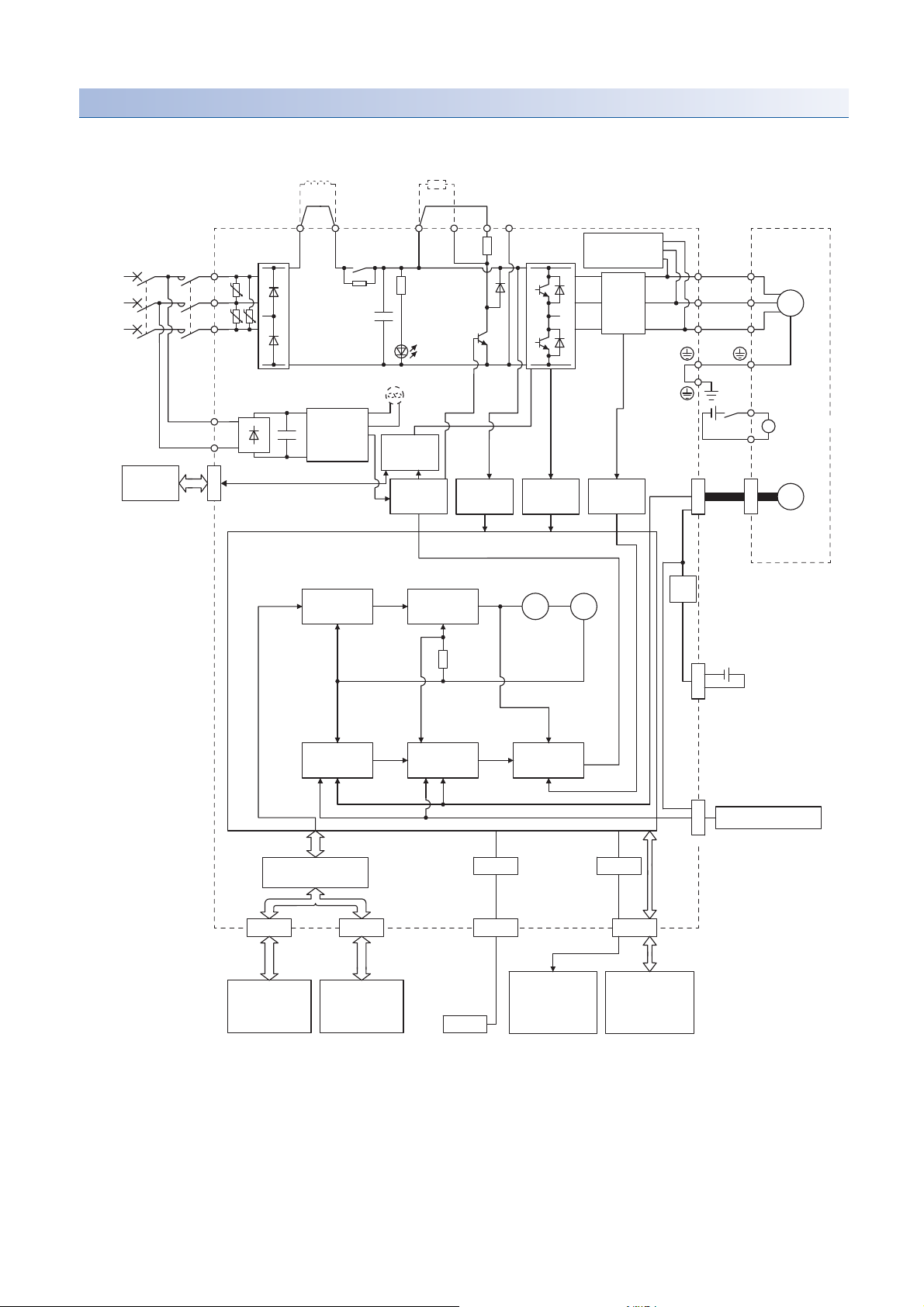
200 V class
Model position
Current
control
Actual
position
control
Actual
speed
control
Virtual
motor
Virtual
encoder
L11
L21
Cooling fan
*3
Encoder
N-CD
L3
L2
L1
Dynamic
brake
circuit
Power factor improving
DC reactor
*6
Current
detection
Overcurrent
protection
Voltage
detection
Power
supply
*2
MCMCCB
Base
amplifier
STO
circuit
CN5
USB
USB
Personal
computer
Controller or
servo amplifier
Controller or
servo amplifier
CN1A
CN1B
D/A
Analog monitor
(2 channels)
Position
command
input
CN3
Servo amplifier
U
V
W
U
V
W
P3
P4
*4
Diode
stack
Relay
P+
+
+
B
RA
24 V DC
B1
B2
Battery
(For absolute position
detection system)
CN4
STO
switch
Model speed Model torque
M
CN2
CN8
Control
circuit
power
supply
Model
position
control
Model
speed
control
I/F Control
Servo motor
CHARGE
lamp
Regenerative
TR
Current
detector
Digital I/O
control
Regenerative
option
UU
U
Stepdown
circuit
Electromagnetic
brake
*1
*5
External encoder
CN2L
■MR-J4-500GF(-RJ) or less
20
1 FUNCTIONS AND CONFIGURATION
1.2 Function block diagram

*1 The built-in regenerative resistor is not provided for MR-J4-10GF(-RJ).
*2 For 1-phase 200 V AC to 240 V AC, connect the power supply to L1 and L3. Leave L2 open. Refer to the following for the power supply
specifications.
Page 30 Servo amplifier standard specifications
*3 Servo amplifiers MR-J4-70GF(-RJ) or more have a cooling fan.
*4 MR-J4 servo amplifier has P3 and P4 in the upstream of the inrush current suppression circuit. They are different from P1 and P2 of MR-
J3 servo amplifiers.
*5 This is for MR-J4-_GF-RJ servo amplifier. MR-J4-_GF servo amplifier does not have CN2L connector.
*6 The power factor improving AC reactor can also be used. In this case, the power factor improving DC reactor cannot be used. When not
using the power factor improving DC reactor, short P3 and P4.
1
1 FUNCTIONS AND CONFIGURATION
1.2 Function block diagram
21
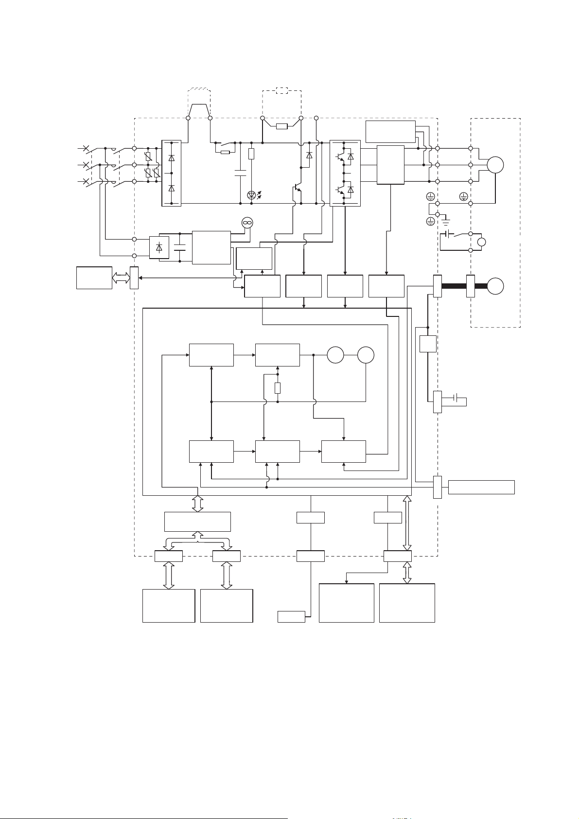
■MR-J4-700GF(-RJ)
L11
L21
Cooling fan
N-C
MCMCCB
STO
circuit
CN5
USB
USB
CN1A
CN1B
D/A
CN3
Servo amplifier
U
V
W
U
V
W
P3
P4
*2
Relay
P+
+
+
B
RA
B1
CN4
M
CN2
CN8
Control
circuit
power
supply
CHARGE
lamp
Regenerative
TR
Regenerative
option
L3
L2
L1
U U
U
Current
detection
Overcurrent
protection
Voltage
detection
Base
amplifier
STO
switch
Servo motor
24 V DC
Encoder
Model position
Current
control
Actual
position
control
Actual
speed
control
Virtual
motor
Virtual
encoder
Position
command
input
Model speed Model torque
Model
position
control
Model
speed
control
Stepdown
circuit
Battery
(For absolute position
detection system)
I/F Control
Personal
computer
Analog monitor
(2 channels)
Digital I/O
control
Diode
stack
CN2L
External encoder
Controller or
servo amplifier
Controller or
servo amplifier
Power factor improving
DC reactor
*4
Power
supply
*1
Electromagnetic
brake
*3
Dynamic
brake
circuit
Current
detector
*1 Refer to the following for the power supply specifications.
Page 30 Servo amplifier standard specifications
*2 MR-J4 servo amplifier has P3 and P4 in the upstream of the inrush current suppression circuit. They are different from P1 and P2 of MR-
J3 servo amplifiers.
*3 This is for MR-J4-_GF-RJ servo amplifier. MR-J4-_GF servo amplifier does not have CN2L connector.
*4 The power factor improving AC reactor can also be used. In this case, the power factor improving DC reactor cannot be used. When not
using the power factor improving DC reactor, short P3 and P4.
1 FUNCTIONS AND CONFIGURATION
22
1.2 Function block diagram

■MR-J4-11KGF(-RJ)/MR-J4-15KGF(-RJ)/MR-J4-22KGF(-RJ)
L11
L21
Encoder
N-C
Power factor improving
DC reactor
*5
MCMCCB
CN5
USB
USB
CN1A
CN1B
D/A
CN3
P3
P4
*2
P+
+
+
B
RA
B1
B2
CN4
M
CN2
CN8
Servo motor
External regenerative
resistor or
regenerative option
L3
L2
L1
U U
U
Thyristor
External
dynamic brake
(optional)
*4*6
U
V
W
U
V
W
Model position
Current
control
Actual
position
control
Actual
speed
control
Virtual
motor
Virtual
encoder
Cooling fan
Current
detection
Overcurrent
protection
Voltage
detection
Power
supply
*1
Base
amplifier
STO
circuit
Personal
computer
Analog monitor
(2 channels)
Position
command
input
Servo amplifier
24 V DC
Battery
(For absolute position
detection system)
STO
switch
Model speed Model torque
Control
circuit
power
supply
Model
position
control
Model
speed
control
I/F Control
CHARGE
lamp
Regenerative
TR
Current
detector
Digital I/O
control
Stepdown
circuit
Electromagnetic
brake
Diode
stack
CN2L
External encoder
Controller or
servo amplifier
Controller or
servo amplifier
*3
1
1 FUNCTIONS AND CONFIGURATION
1.2 Function block diagram
23

*1 Refer to the following for the power supply specifications.
Page 30 Servo amplifier standard specifications
*2 MR-J4 servo amplifier has P3 and P4 in the upstream of the inrush current suppression circuit. They are different from P1 and P2 of MR-
J3 servo amplifiers.
*3 This is for MR-J4-_GF-RJ servo amplifier. MR-J4-_GF servo amplifier does not have CN2L connector.
*4 Use an external dynamic brake for this servo amplifier. Failure to do so will cause an accident because the servo motor does not stop
immediately but coasts at an alarm occurrence for which the servo motor does not decelerate to stop. Ensure the safety in the entire
equipment. For alarms for which the servo motor does not decelerate to stop, refer to the following.
Page 280 TROUBLESHOOTING
*5 The power factor improving AC reactor can also be used. In this case, the power factor improving DC reactor cannot be used. When not
using the power factor improving DC reactor, short P3 and P4.
*6 The external dynamic brake cannot be used for compliance with SEMI-F47 standard. Do not assign DB (Dynamic brake interlock) in [Pr.
PD07] to [Pr. PD09]. Failure to do so will cause the servo amplifier to become servo-off when an instantaneous power failure occurs.
24
1 FUNCTIONS AND CONFIGURATION
1.2 Function block diagram
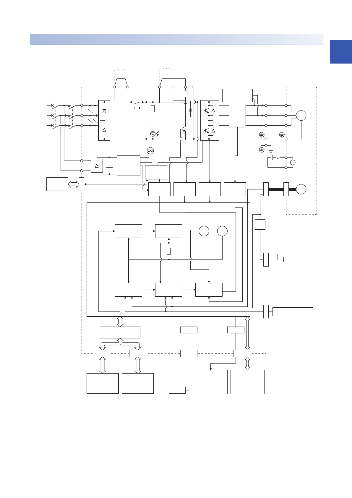
400 V class
Model position
Current
control
Actual
position
control
Actual
speed
control
Virtual
motor
Virtual
encoder
L11
L21
Cooling fan
*2
Encoder
N-CD
L3
L2
L1
Dynamic
brake
circuit
Current
detection
Overcurrent
protection
Voltage
detection
Power
supply
*1
MCMCCB
Base
amplifier
STO
circuit
CN5
USB
USB
Personal
computer
CN1A
CN1B
D/A
Analog monitor
(2 channels)
Position
command
input
CN3
Servo amplifier
U
V
W
U
V
W
P3 P4
*3
Diode
stack
Relay
P+
+
+
B
RA
24 V DC
B1
B2
Battery
(For absolute position
detection system)
CN4
STO
switch
Model speed Model torque
M
CN2
CN8
Control
circuit
power
supply
Model
position
control
Model
speed
control
I/F Control
Servo motor
Charge
lamp
Regenerative
TR
Current
detector
Digital I/O
control
Regenerative
option
U U
U
Stepdown
circuit
Power factor improving
DC reactor
*5
CN2L
External encoder
Controller or
servo amplifier
Controller or
servo amplifier
*4
Electromagnetic
brake
■MR-J4-350GF4(-RJ) or less
1
*1 Refer to the following for the power supply specification.
Page 30 Servo amplifier standard specifications
*2 Servo amplifiers MR-J4-200GF4(-RJ) or more have a cooling fan.
*3 MR-J4 servo amplifier has P3 and P4 in the upstream of the inrush current suppression circuit. They are different from P1 and P2 of MR-
J3 servo amplifiers.
*4 This is for MR-J4-_GF4-RJ servo amplifier. MR-J4-_GF4 servo amplifier does not have CN2L connector.
*5 The power factor improving AC reactor can also be used. In this case, the power factor improving DC reactor cannot be used. When not
using the power factor improving DC reactor, short P3 and P4.
1 FUNCTIONS AND CONFIGURATION
1.2 Function block diagram
25

■MR-J4-500GF4(-RJ)/MR-J4-700GF4(-RJ)
Dynamic
brake
circuit
Current
detector
Virtual
motor
Virtual
encoder
L11
L21
Cooling fan
Encoder
N-C
Current
detection
Overcurrent
protection
Voltage
detection
Power
supply
*1
MCMCCB
Base
amplifier
STO
circuit
CN5
USB
USB
CN1A
CN1B
D/A
Position
command
input
CN3
Servo amplifier
Diode
stack
U
V
W
U
V
W
P3 P4
*2
Relay
P+
+
+
B
RA
24 V DC
B1
B2
Battery
(For absolute position
detection system)
CN4
STO
switch
M
CN2
CN8
Control
circuit
power
supply
Model
position
control
Model
speed
control
Servo motor
Regenerative
option
L3
L2
L1
U U
U
Stepdown
circuit
Power factor improving
DC reactor
*4
Charge
lamp
Regenerative
TR
Electromagnetic
brake
Model position Model speed Model torque
Current
control
Actual
position
control
Actual
speed
control
I/F Control
Personal
computer
Analog monitor
(2 channels)
Digital I/O
control
CN2L
External encoder
Controller or
servo amplifier
Controller or
servo amplifier
*3
*1 Refer to the following for the power supply specification.
Page 30 Servo amplifier standard specifications
*2 MR-J4 servo amplifier has P3 and P4 in the upstream of the inrush current suppression circuit. They are different from P1 and P2 of MR-
J3 servo amplifiers.
*3 This is for MR-J4-_GF4-RJ servo amplifier. MR-J4-_GF4 servo amplifier does not have CN2L connector.
*4 The power factor improving AC reactor can also be used. In this case, the power factor improving DC reactor cannot be used. When not
using the power factor improving DC reactor, short P3 and P4.
1 FUNCTIONS AND CONFIGURATION
26
1.2 Function block diagram
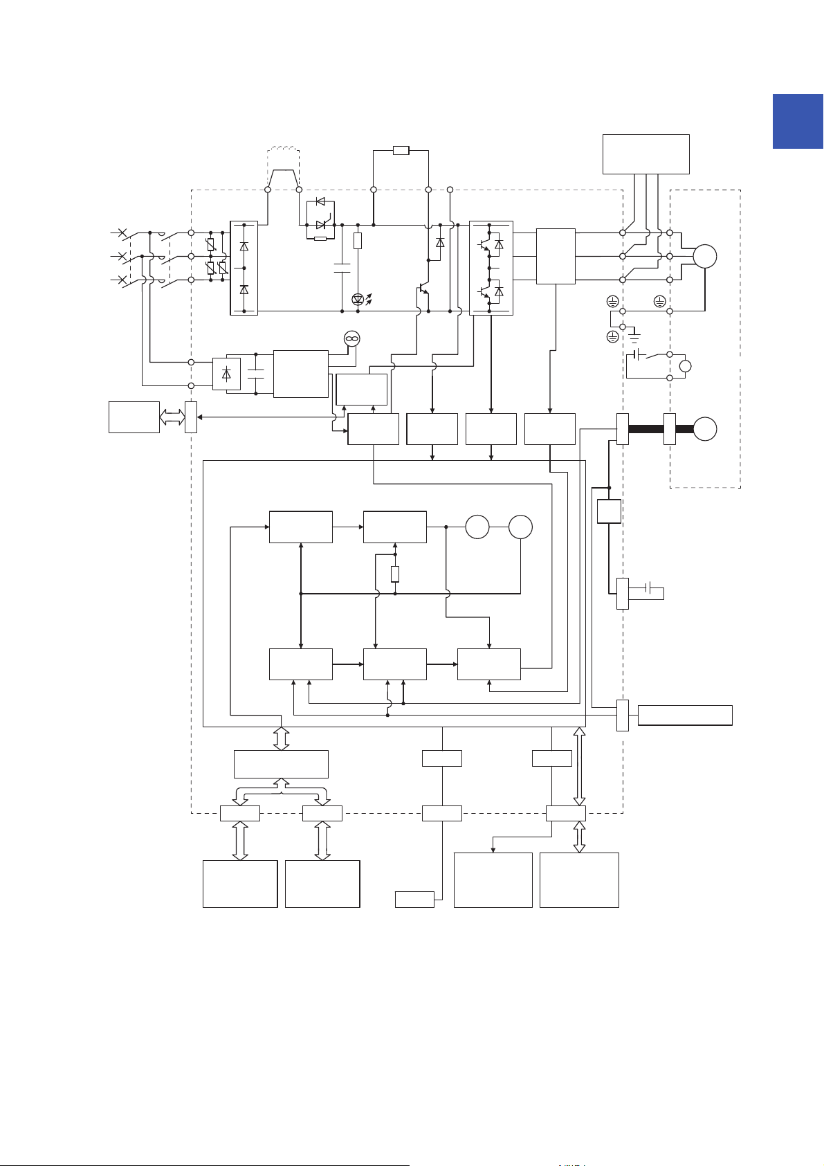
Current
detector
Thyristor
External
dynamic brake
(optional)
*4*6
U
V
W
U
V
W
L3
L2
L1
U U
U
Power factor improving
DC reactor
*4
Charge
lamp
Regenerative
TR
Cooling fan
L11
L21
Encoder
N-C
Power
supply
*1
MCMCCB
CN5
USB
USB
CN1A
CN1B
D/A
CN3
Servo amplifier
Diode
stack
P3 P4
*2
P+
+
+
B
RA
24 V DC
B1
B2
Battery
(For absolute position
detection system)
CN4
M
CN2
CN8
Servo motor
External
regenerative resistor
or
regenerative option
Electromagnetic
brake
STO
switch
Control
circuit
power
supply
Current
detection
Overcurrent
protection
Voltage
detection
Base
amplifier
STO
circuit
Stepdown
circuit
Model position
Current
control
Actual
position
control
Actual
speed
control
Virtual
motor
Virtual
encoder
Position
command
input
Model speed Model torque
Model
position
control
Model
speed
control
Personal
computer
Analog monitor
(2 channels)
Digital I/O
control
I/F Control
CN2L
External encoder
Controller or
servo amplifier
Controller or
servo amplifier
*3
■MR-J4-11KGF4(-RJ)/MR-J4-15KGF4(-RJ)/MR-J4-22KGF4(-RJ)
1
1 FUNCTIONS AND CONFIGURATION
1.2 Function block diagram
27

*1 Refer to the following for the power supply specification.
Page 30 Servo amplifier standard specifications
*2 MR-J4 servo amplifier has P3 and P4 in the upstream of the inrush current suppression circuit. They are different from P1 and P2 of MR-
J3 servo amplifiers.
*3 This is for MR-J4-_GF4-RJ servo amplifier. MR-J4-_GF4 servo amplifier does not have CN2L connector.
*4 Use an external dynamic brake for this servo amplifier. Failure to do so will cause an accident because the servo motor does not stop
immediately but coasts at an alarm occurrence for which the servo motor does not decelerate to stop. Ensure the safety in the entire
equipment. For alarms for which the servo motor does not decelerate to stop, refer to the following.
Page 280 TROUBLESHOOTING
*5 The power factor improving AC reactor can also be used. In this case, the power factor improving DC reactor cannot be used. When not
using the power factor improving DC reactor, short P3 and P4.
*6 The external dynamic brake cannot be used for compliance with SEMI-F47 standard. Do not assign DB (Dynamic brake interlock) in [Pr.
PD07] to [Pr. PD09]. Failure to do so will cause the servo amplifier to become servo-off when an instantaneous power failure occurs.
28
1 FUNCTIONS AND CONFIGURATION
1.2 Function block diagram

100 V class
Model position
Current
control
Actual
position
control
Actual
speed
control
Virtual
motor
Virtual
encoder
L11
L21
Encoder
N-
*1
CD
L2
L1
Dynamic
brake circuit
Current
detection
Overcurrent
protection
Voltage
detection
Power
supply
*2
MCMCCB
Base
amplifier
STO
circuit
Position
command
input
Servo amplifier
U
V
W
U
V
W
Diode stack
Relay
P+
+
+
B
RA
24 V DC
B1
B2
Battery
(For absolute position
detection system)
CN4
STO
switch
Model speed Model torque
M
CN2
CN8
Control
circuit
power
supply
Model
position
control
Model
speed
control
Servo motor
Charge
lamp
Regene-
rative
TR
Current
detector
Regenerative
option
U
Stepdown
circuit
External encoder
+
CN5
USB
USB
Personal
computer
Controller or
servo amplifier
Controller or
servo amplifier
CN1A
CN1B
D/A
Analog monitor
(2 channels)
CN3
I/F Control
Digital I/O
control
*3
CN2L
Electromagnetic
brake
1
*1 The built-in regenerative resistor is not provided for MR-J4-10GF1(-RJ).
*2 Refer to the following for the power supply specifications.
Page 30 Servo amplifier standard specifications
*3 This is for MR-J4-_GF1-RJ servo amplifier. MR-J4-_GF1 servo amplifier does not have CN2L connector.
1 FUNCTIONS AND CONFIGURATION
1.2 Function block diagram
29

1.3 Servo amplifier standard specifications
200 V class
Model: MR-J4-_(-RJ) 10GF 20GF 40GF 60GF 70GF 100GF 200GF 350GF 500GF 700GF 11K GF 15KGF 22KGF
Output Rated voltage 3-phase 170 V AC
Rated current [A] 1.1 1.5 2.8 3.2 5.8 6.0 11.0 17.0 28.0 37.0 68.0 87.0 126.0
Output frequency Less than 590 Hz
Output frequency
accuracy
Main circuit
power supply
input
Control
circuit power
supply input
Interface
power supply
Control method Sine-wave PWM control, current control method
Dynamic brake Built-in External option
CC-Link IE Field communication cycle
*12
Fully closed loop control Compatible
Scale measurement function Compatible
Load-side encoder interface
Communication function USB: connection to a personal computer or others (MR Configurator2-compatible)
Encoder output pulses Compatible (A/B/Z-phase pulse)
Analog monitor Two channels
Protective functions Overcurrent shut-off, regenerative overvoltage shut-off, overload shut-off (electronic thermal), servo motor overheat
Functional safety STO (IEC/EN 61800-5-2)
Voltage/
Frequency
Rated current
Permissible
voltage
fluctuation
Permissible frequency
fluctuation
Power supply capacity
[kVA]
Inrush current [A] Page 325 Inrush currents at power-on of main circuit and control circuit
Voltage/
Frequency
Rated current [A] 0.2 0.3
Permissible
voltage
fluctuation
Permissible frequency
fluctuation
Power consumption [W] 30 45
Inrush current [A] Page 325 Inrush currents at power-on of main circuit and control circuit
Voltage 24 V DC 10%
Current capacity [A] 0.3 (including CN8 connector signals)
At AC
input
At DC
input
*5
At AC
input
At DC
input
At AC
input
At DC
input
At AC
input
At DC
input
*11
0.01%
3-phase or 1-phase 200 V AC to 240 V
AC, 50 Hz/60 Hz
283 V DC to 340 V DC
*8
[A] 0.9 1.5 2.6 3.2 *63.8 5.0 10.5 16.0 21.7 28.9 46.0 64.0 95.0
3-phase or 1-phase 170 V AC to 264 V AC3-phase or 1-
241 V DC to 374 V DC
*8
Within 5%
Page 315 Power supply capacity and generated loss
1-phase 200 V AC to 240 V AC, 50 Hz/60 Hz
283 V DC to 340 V DC
*8
1-phase 170 V AC to 264 V AC
241 V DC to 374 V DC
*8
Within 5%
0.5 ms, 1.0 ms, 2.0 ms, 4.0 ms
*15
*15
Mitsubishi Electric serial interface
protection, encoder error protection, regenerative error protection, undervoltage protection, instantaneous power failure
protection, overspeed protection, error excessive protection, magnetic pole detection protection, and linear servo control
fault protection
3-phase or 1phase 200 V AC
to 240 V AC, 50
Hz/60 Hz
phase 170 V AC
to 264 V AC
*1
3-phase 200 V AC to 240 V AC, 50 Hz/60 Hz
*7
3-phase 170 V AC to 264 V AC
*7
*13*14
30
1 FUNCTIONS AND CONFIGURATION
1.3 Servo amplifier standard specifications

Model: MR-J4-_(-RJ) 10GF 20GF 40GF 60GF 70GF 100GF 200GF 350GF 500GF 700GF 11K GF 15KGF 22KGF
Safety
performance
Compliance
to global
standards
Structure (IP rating) Natural cooling, open (IP20) Force cooling, open (IP20) Force cooling, open (IP20)
Close
mounting
Environment Ambient
Mass [kg] 1.0 1.4 2.1 2.3 4.0 6.2 13.4 13.4 18.2
Standards certified by
*10
CB
Response performance 8 ms or less (STO input off energy shut off)
Test pulse input (STO)
*3
Mean time to
dangerous failure
(MTTFd)
Diagnostic coverage
(DC)
Probability of
dangerous Failure per
Hour (PFH)
CE marking LVD: EN 61800-5-1
UL standard UL 508C
3-phase power supply
*2
input
1-phase power supply
input
temperature
Ambient
humidity
Ambience Indoors (no direct sunlight); no corrosive gas, inflammable gas, oil mist or dust
Altitude 2000 m or less above sea level
Vibration resistance 5.9 m/, at 10 Hz to 55 Hz (directions of X, Y and Z axes)
Operation 0 to 55 (non-freezing)
Storage -20 to 65 (non-freezing)
Operation 5 %RH to 90 %RH (non-condensing)
Storage
EN ISO 13849-1 category 3 PL e, IEC 61508 SIL 3, EN 62061 SIL CL3, and EN 61800-5-2
Test pulse interval: 1 Hz to 25 Hz
Test pulse off time: Up to 1 ms
MTTFd 100 [years] (314a)
DC = Medium, 97.6 [%]
-9
PFH = 6.4 10
EMC: EN 61800-3
MD: EN ISO 13849-1, EN 61800-5-2, EN 62061
Possible Impossible
Possible Impossible
[1/h]
*9
*4
*1 0.3 A is the value applicable when all I/O signals are used. The current capacity can be decreased by reducing the number of I/O points.
*2 When closely mounting the servo amplifier, operate it at an ambient temperature of 0 to 45 or at 75% or smaller effective load ratio.
*3 Test pulse is a signal which instantaneously turns off a signal to the servo amplifier at a constant period for external circuit to self-
diagnose.
*4 Except for the terminal block.
*5 This value is applicable when a 3-phase power supply is used.
*6 The rated current is 2.9 A when the servo amplifier is used with a UL or CSA compliant servo motor.
*7 When using 1-phase 200 V AC to 240 V AC power supply, operate the servo amplifier at 75% or smaller effective load ratio.
*8 The DC power supply input is available only with MR-J4-_GF-RJ servo amplifiers. For the connection example of the power circuit when
a DC input is used, refer to the following.
Page 563 When using the servo amplifier with the DC power supply input
*9 Follow the restrictions below when using the servo amplifiers at altitude exceeding 1000 m and up to 2000 m above sea level.
Page 81 Restrictions when using the servo amplifiers at altitude exceeding 1000 m and up to 2000 m above sea level
*10 The safety level depends on the setting value of [Pr. PF18 STO diagnosis error detection time] and whether STO input diagnosis by
TOFB output is performed or not. For details, refer to the Function column of [Pr. PF18] below.
Page 215 Extension setting 3 parameters ([Pr. PF_ _ ])
*11 The MR-J4-_GF servo amplifier is compatible only with the two-wire type. The MR-J4-_GF-RJ servo amplifier is compatible with the two-
wire type, four-wire type, and A/B/Z-phase differential output method.
Page 18 Summary
*12 The communication cycle depends on the controller specifications and the number of axes connected.
*13 Use an external dynamic brake for this servo amplifier. Failure to do so will cause an accident because the servo motor does not stop
immediately but coasts at emergency stop. Ensure the safety in the entire equipment.
*14 The external dynamic brake cannot be used for compliance with SEMI-F47 standard. Do not assign DB (Dynamic brake interlock) in [Pr.
PD07] to [Pr. PD09]. Doing so will cause the servo amplifier to become servo-off when an instantaneous power failure occurs.
*15 This is used with servo amplifiers with software version A1 or later.
1
1 FUNCTIONS AND CONFIGURATION
1.3 Servo amplifier standard specifications
31

400 V class
Model: MR-J4-_(-RJ) 60GF4 100GF4 200GF4 350GF4 500GF4 700GF4 11 KGF 4 15KGF4 22KGF4
Output Rated voltage 3-phase 323 V AC
Rated current [A] 1.5 2.8 5.4 8.6 14.0 17.0 32.0 41.0 63.0
Output frequency Less than 590 Hz
Output frequency
accuracy
Main circuit
power supply
input
Control circuit
power supply
input
Interface
power supply
Control method Sine-wave PWM control, current control method
Dynamic brake Built-in External option
CC-Link IE Field communication cycle *70.5 ms, 1.0 ms, 2.0 ms, 4.0 ms
Fully closed loop control Compatible
Scale measurement function Compatible
Load-side encoder interface
Communication function USB: connection to a personal computer or others (MR Configurator2-compatible)
Encoder output pulses Compatible (A/B/Z-phase pulse)
Analog monitor Two channels
Protective functions Overcurrent shut-off, regenerative overvoltage shut-off, overload shut-off (electronic thermal), servo motor overheat
Functional safety STO (IEC/EN 61800-5-2)
Safety
performance
Compliance
to global
standards
Close mounting Impossible
Structure (IP rating) Natural cooling, open
Voltage/Frequency 3-phase 380 V AC to 480 V AC, 50 Hz/60 Hz
Rated current [A] 1.4 2.5 5.1 7.9 10.8 14.4 23.1 31.8 47.6
Permissible voltage
fluctuation
Permissible frequency
fluctuation
Power supply capacity
[kVA]
Inrush current [A] Page 325 Inrush currents at power-on of main circuit and control circuit
Voltage/Frequency 1-phase 380 V AC to 480 V AC, 50 Hz/60 Hz
Rated current [A] 0.1 0.2
Permissible voltage
fluctuation
Permissible frequency
fluctuation
Power consumption [W] 30 45
Inrush current [A] Page 325 Inrush currents at power-on of main circuit and control circuit
Voltage 24 V DC 10%
Current capacity [A] 0.3 (including CN8 connector signals)
*6
Standards certified by CB
*5
Response performance 8 ms or less (STO input off energy shut off)
Test pulse input (STO)
Mean time to dangerous
failure (MTTFd)
Diagnostic coverage (DC) DC = Medium, 97.6 [%]
Probability of dangerous
Failure per Hour (PFH)
CE marking LVD: EN 61800-5-1
UL standard UL 508C
0.01%
3-phase 323 V AC to 528 V AC
Within 5%
Page 315 Power supply capacity and generated loss
1-phase 323 V AC to 528 V AC
Within 5%
*1
*8*9
*10
*10
Mitsubishi Electric serial interface
protection, encoder error protection, regenerative error protection, undervoltage protection, instantaneous power
failure protection, overspeed protection, error excessive protection, magnetic pole detection protection, and linear
servo control fault protection
EN ISO 13849-1 category 3 PL e, IEC 61508 SIL 3, EN 62061 SIL CL3, and EN 61800-5-2
*2
Test pulse interval: 1 Hz to 25 Hz
Test pulse off time: Up to 1 ms
MTTFd 100 [years] (314a)
-9
PFH = 6.4 10
EMC: EN 61800-3
MD: EN ISO 13849-1, EN 61800-5-2, EN 62061
(IP20)
[1/h]
Force cooling, open
(IP20)
Force cooling, open (IP20)
*3
32
1 FUNCTIONS AND CONFIGURATION
1.3 Servo amplifier standard specifications

Model: MR-J4-_(-RJ) 60GF4 100GF4 200GF4 350GF4 500GF4 700GF4 11 KGF 4 15KGF4 22KGF4
Environment Ambient
temperature
Ambient
humidity
Ambience Indoors (no direct sunlight); no corrosive gas, inflammable gas, oil mist or dust
Altitude 2000 m or less above sea level
Vibration resistance 5.9 m/, at 10 Hz to 55 Hz (directions of X, Y and Z axes)
Mass [kg] 1.7 2.1 3.6 4.3 6.5 13.4 13.4 18.2
*1 0.3 A is the value applicable when all I/O signals are used. The current capacity can be decreased by reducing the number of I/O points.
*2 Test pulse is a signal which instantaneously turns off a signal to the servo amplifier at a constant period for external circuit to self-
diagnose.
*3 Except for the terminal block.
*4 Follow the restrictions below when using the servo amplifiers at altitude exceeding 1000 m and up to 2000 m above sea level.
Page 81 Restrictions when using the servo amplifiers at altitude exceeding 1000 m and up to 2000 m above sea level
*5 The safety level depends on the setting value of [Pr. PF18 STO diagnosis error detection time] and whether STO input diagnosis by
TOFB output is performed or not. For details, refer to the Function column of [Pr. PF18] below.
Page 215 Extension setting 3 parameters ([Pr. PF_ _ ])
*6 The MR-J4-_GF servo amplifier is compatible only with the two-wire type. The MR-J4-_GF-RJ servo amplifier is compatible with the two-
wire type, four-wire type, and A/B/Z-phase differential output method.
Page 18 Summary
*7 The communication cycle depends on the controller specifications and the number of axes connected.
*8 Use an external dynamic brake for this servo amplifier. Failure to do so will cause an accident because the servo motor does not stop
immediately but coasts at emergency stop. Ensure the safety in the entire equipment.
*9 The external dynamic brake cannot be used for compliance with SEMI-F47 standard. Do not assign DB (Dynamic brake interlock) in [Pr.
PD07] to [Pr. PD09]. Doing so will cause the servo amplifier to become servo-off when an instantaneous power failure occurs.
*10 This is used with servo amplifiers with software version A1 or later.
Operation 0 to 55 (non-freezing)
Storage -20 to 65 (non-freezing)
Operation 5 %RH to 90 %RH (non-condensing)
Storage
*4
1
1 FUNCTIONS AND CONFIGURATION
1.3 Servo amplifier standard specifications
33

100 V class
Model: MR-J4-_(-RJ) 10GF1 20GF1 40GF1
Output Rated voltage 3-phase 170 V AC
Rated current [A] 1.1 1.5 2.8
Output frequency Less than 590 Hz
Main circuit
power supply
input
Control circuit
power supply
input
Interface
power supply
Output frequency
accuracy
Voltage/Frequency 1-phase 100 V AC to 120 V AC, 50 Hz/60 Hz
Rated current [A] 3.0 5.0 9.0
Permissible voltage
fluctuation
Permissible frequency
fluctuation
Power supply capacity
[kVA]
Inrush current [A] Page 325 Inrush currents at power-on of main circuit and control circuit
Voltage/Frequency 1-phase 100 V AC to 120 V AC, 50 Hz/60 Hz
Rated current [A] 0.4
Permissible voltage
fluctuation
Permissible frequency
fluctuation
Power consumption [W] 30
Inrush current [A] Page 325 Inrush currents at power-on of main circuit and control circuit
Voltage DC 24 V 10%
Current capacity [A] 0.3 (including CN8 connector signals)
0.01%
1-phase 85 V AC to 132 V AC
Within 5%
Page 315 Power supply capacity and generated loss
1-phase 85 V AC to 132 V AC
Within 5%
*1
Control method Sine-wave PWM control, current control method
Dynamic brake Built-in
*7
CC-Link IE Field communication cycle
Fully closed loop control Supported
Scale measurement function Supported
Load-side encoder interface
Communication function USB: connection to a personal computer or others (MR Configurator2-compatible)
Encoder output pulses Compatible (A/B/Z-phase pulse)
Analog monitor Two channels
Protective functions Overcurrent shut-off, regenerative overvoltage shut-off, overload shut-off (electronic thermal), servo motor overheat
Functional safety STO (IEC/EN 61800-5-2)
Safety
performance
Compliance
with global
standards
Structure (IP rating) Natural cooling, open (IP20)
Close mounting
Standards certified by CB
*5
Response performance 8 ms or less (STO input off energy shut off)
Test pulse input (STO)
Mean time to dangerous
failure (MTTFd)
Diagnostic coverage (DC) DC = High, 97.6 [%]
Probability of dangerous
Failure per Hour (PFH)
CE marking LVD: EN 61800-5-1
UL standard UL 508C
*2
*6
0.5 ms, 1.0 ms, 2.0 ms, 4.0 ms
Mitsubishi Electric serial interface
protection, encoder error protection, regenerative error protection, undervoltage protection, instantaneous power
failure protection, overspeed protection, error excessive protection, magnetic pole detection protection, and linear
servo control error protection
EN ISO 13849-1 Category 3 PL e, IEC 61508 SIL 3, EN 62061 SIL CL3, and EN 61800-5-2
*3
Test pulse interval: 1 Hz to 25 Hz
Test pulse off time: Up to 1 ms
MTTFd 100 [years] (314a)
-9
PFH = 6.4 10
EMC: EN 61800-3
MD: EN ISO 13849-1, EN 61800-5-2, EN 62061
Possible
[1/h]
34
1 FUNCTIONS AND CONFIGURATION
1.3 Servo amplifier standard specifications

Model: MR-J4-_(-RJ) 10GF1 20GF1 40GF1
Environment Ambient
temperature
Ambient
humidity
Ambience Indoors (no direct sunlight), free from corrosive gas, flammable gas, oil mist, dust, and dirt
Altitude 2000 m or less above sea level
Vibration resistance 5.9 m/, at 10 Hz to 55 Hz (X, Y, Z axes)
Mass [kg] 1.0
*1 0.3 A is the value applicable when all I/O signals are used. The current capacity can be decreased by reducing the number of I/O points.
*2 When closely mounting the servo amplifiers, operate them at the ambient temperature of 0 to 45 or at 75% or smaller effective
load ratio.
*3 Test pulse is a signal which instantaneously turns off a signal to the servo amplifier at a constant period for external circuit to self-
diagnose.
*4 Follow the restrictions below when using this product at altitude exceeding 1000 m and up to 2000 m above sea level.
Page 81 Restrictions when using the servo amplifiers at altitude exceeding 1000 m and up to 2000 m above sea level
*5 The safety level depends on the setting value of [Pr. PF18 STO diagnosis error detection time] and whether STO input diagnosis by
TOFB output is performed or not. For details, refer to the Function column of [Pr. PF18] as follows.
Page 215 Detailed list of parameters
*6 The MR-J4-_GF1 servo amplifier is compatible only with the two-wire type. The MR-J4-_GF1-RJ servo amplifier is compatible with the
two-wire type, four-wire type, and A/B/Z-phase differential output method.
Page 18 Summary
*7 The communication cycle depends on the controller specifications and the number of axes connected.
Operation 0 to 55 (non-freezing)
Storage -20 to 65 (non-freezing)
Operation 5 %RH to 90 %RH (non-condensing)
Storage
*4
1
1 FUNCTIONS AND CONFIGURATION
1.3 Servo amplifier standard specifications
35

1.4 Combinations of servo amplifiers and servo
motors
• When a 1-phase 200 V AC input is used, the maximum torque of 400% cannot be achieved with HG-JR
series servo motor.
• When you use the MR-J4-100GF(-RJ) or MR-J4-200GF(-RJ) with the 1-phase 200 V AC input, contact your
local sales office for the torque characteristics of the HG-UR series and HG-RR series servo motors.
200 V class
Servo amplifier Rotary servo motor Linear servo motor
HG-KR HG-MR HG-SR HG-UR HG-RR HG-JR
MR-J4-10GF(-RJ) 053
13
MR-J4-20GF(-RJ) 23 23 LM-U2PAB-05M-0SS0
MR-J4-40GF(-RJ) 43 43 LM-H3P2A-07P-BSS0
MR-J4-60GF(-RJ) 51
MR-J4-70GF(-RJ) 73 73 72 73 LM-H3P3B-24P-CSS0
MR-J4-100GF(-RJ) 81
MR-J4-200GF(-RJ) 121
MR-J4-350GF(-RJ) 301
MR-J4-500GF(-RJ) 421
MR-J4-700GF(-RJ) 702 503
MR-J4-11KGF(-RJ) 801
MR-J4-15KGF(-RJ) 15K1
053
13
53 LM-U2PBD-15M-1SS0 TM-RFM006C20
52
102
201
152
202
352
502
53
152 103
153
202 203 153
352
502
353
503
103
73
103
153
203
203
353
353
503
601
701M
703
12K1
11K 1M
903
15K1M
(primary side)
LM-U2PBB-07M-1SS0
LM-H3P3A-12P-CSS0
LM-K2P1A-01M-2SS1
LM-U2PAD-10M-0SS0
LM-U2PAF-15M-0SS0
LM-H3P3C-36P-CSS0
LM-H3P7A-24P-ASS0
LM-K2P2A-02M-1SS1
LM-U2PBF-22M-1SS0
*3
TM-RFM018E20
*3
LM-H3P3D-48P-CSS0
*3
LM-H3P7B-48P-ASS0
LM-H3P7C-72P-ASS0
LM-FP2B-06M-1SS0
LM-K2P1C-03M-2SS1
LM-U2P2B-40M-2SS0
*3
LM-H3P7D-96P-ASS0
*3
LM-K2P2C-07M-1SS1
LM-K2P3C-14M-1SS1
LM-U2P2C-60M-2SS0
*3
LM-FP2D-12M-1SS0
LM-FP4B-12M-1SS0
LM-K2P2E-12M-1SS1
LM-K2P3E-24M-1SS1
LM-U2P2D-80M-2SS0
*3
LM-FP2F-18M-1SS0
LM-FP4D-24M-1SS0
LM-FP4F-36M-1SS0
LM-FP4F-48M-1SS0
*1
Direct drive motor
TM-RFM002C20
TM-RG2M002C30
TM-RU2M002C30
TM-RG2M004E30
TM-RU2M004E30
TM-RFM004C20
TM-RG2M004E30
TM-RU2M004E30
TM-RG2M009G30
TM-RU2M009G30
TM-RFM006E20
TM-RFM012E20
TM-RFM012G20
TM-RFM040J10
TM-RFM048G20
TM-RFM072G20
TM-RFM120J10
TM-RFM240J10
*1
*2
*2
*2
*2
*2*4
*2*4
*2
*2
36
1 FUNCTIONS AND CONFIGURATION
1.4 Combinations of servo amplifiers and servo motors

Servo amplifier Rotary servo motor Linear servo motor
HG-KR HG-MR HG-SR HG-UR HG-RR HG-JR
MR-J4-22KGF(-RJ) 20K1
25K1
22K1M
(primary side)
*1
Direct drive motor
*1 This is available with servo amplifiers with software version A1 or later.
*2 This is available with servo amplifiers with software version A5 or later.
*3 This combination increases the maximum torque of the servo motor to 400%.
*4 The combination increases the rated torque and the maximum torque.
400 V class
Servo amplifier Rotary servo motor Linear servo motor (primary side)
HG-SR HG-JR
MR-J4-60GF4(-RJ) 524 534
MR-J4-100GF4(-RJ) 1024 534
MR-J4-200GF4(-RJ) 1524
2024
MR-J4-350GF4(-RJ) 3524 1534
MR-J4-500GF4(-RJ) 5024 3534
MR-J4-700GF4(-RJ) 7024 5034
MR-J4-11KGF4(-RJ) 8014
MR-J4-15KGF4(-RJ) 15K14
MR-J4-22KGF4(-RJ) 20K14
*2
734
1034
*2
734
*2
1034
1534
2034
*2
*2
2034
3534
*2
5034
*2
6014
701M4
7034
12K14
11K 1M4
9034
15K1M4
25K14
22K1M4
*1 This is available with servo amplifiers with software version A1 or later.
*2 The combination is for increasing the maximum torque of the servo motor to 400%.
LM-FP5H-60M-1SS0
*1
1
*1
100 V class
Servo amplifier Rotary servo motor Linear servo motor
HG-KR HG-MR
MR-J4-10GF1(-RJ) 053
13
MR-J4-20GF1(-RJ) 23 23 LM-U2PAB-05M-0SS0
MR-J4-40GF1(-RJ) 43 43 LM-H3P2A-07P-BSS0
053
13
*1 The combination increases the rated torque and the maximum torque.
(primary side)
LM-U2PBB-07M-1SS0
LM-H3P3A-12P-CSS0
LM-K2P1A-01M-2SS1
LM-U2PAD-10M-0SS0
LM-U2PAF-15M-0SS0
1 FUNCTIONS AND CONFIGURATION
1.4 Combinations of servo amplifiers and servo motors
Direct drive motor
TM-RFM002C20
TM-RG2M002C30
TM-RU2M002C30
TM-RG2M004E30
TM-RU2M004E30
TM-RFM004C20
TM-RG2M004E30
TM-RU2M004E30
TM-RG2M009G30
TM-RU2M009G30
*1
*1
37

1.5 Function list
The following table lists the functions of this servo. For details of the functions, refer to each section of the detailed explanation
field.
Function Description Detailed
explanation
Model adaptive control This realizes a high response and stable control following the ideal model. The two-degrees-of-
freedom-model model adaptive control enables you to set a response to the command and
response to the disturbance separately.
Additionally, this function can be disabled. Refer to the following for disabling this function.
Page 275 Model adaptive control disabled
Cyclic synchronous position mode
(CSP)
Cyclic synchronous velocity mode
(CSV)
Cyclic synchronous torque mode
(CST)
Touch probe When the touch probe signal is turned on, the current position is latched. This is used with servo
High-resolution encoder High-resolution encoder of 4194304 pulses/rev is used as the encoder of the rotary servo motor
Absolute position detection system Merely setting a home position once makes home position return unnecessary at every power-on. Page 447
Gain switching function You can switch gains during rotation and during stop, and can use an input device to switch gains
Advanced vibration suppression
control
Machine resonance suppression
filter
Shaft resonance suppression filter When a load is mounted to the servo motor shaft, resonance by shaft torsion during driving may
Adaptive filter Servo amplifier detects mechanical resonance and sets filter characteristics automatically to
Low-pass filter Suppresses high-frequency resonance which occurs as servo system response is increased. Page 253
Machine analyzer function Analyzes the frequency characteristic of the mechanical system by simply connecting a MR
Robust filter This function provides better disturbance response in case low response level that load to motor
Slight vibration suppression control Suppresses vibration of 1 pulse produced at a servo motor stop. [Pr. PB24]
Auto tuning Automatically adjusts the gain to optimum value if load applied to the servo motor shaft varies. Page 237
Brake unit Used when the regenerative option cannot provide enough regenerative power.
Operation is performed in the cyclic synchronous position mode.
Operation is performed in the cyclic synchronous velocity mode.
Operation is performed in the cyclic synchronous torque mode.
amplifiers with software version A1 or later.
compatible with the MELSERVO-J4 series.
during operation.
This function suppresses vibration at the arm end or residual vibration. Page 254
This is a filter function (notch filter) which decreases the gain of the specific frequency to suppress
the resonance of the mechanical system.
generate a mechanical vibration at high frequency. The shaft resonance suppression filter
suppresses the vibration.
suppress mechanical vibration.
Configurator2 installed personal computer and servo amplifier.
MR Configurator2 is necessary for this function.
inertia ratio is high for such as roll send axes.
Can be used for the 5 kW or more servo amplifier.
Page 544
Touch probe
ABSOLUTE
POSITION
DETECTION
SYSTEM
Page 259
Gain switching
function
Advanced
vibration
suppression
control II
Page 247
Machine
resonance
suppression
filter
Page 252
Shaft
resonance
suppression
filter
Page 250
Adaptive filter II
Low-pass filter
[Pr. PE41]
Auto tuning
Page 353
FR-BU2-(H)
brake unit
38
1 FUNCTIONS AND CONFIGURATION
1.5 Function list

Function Description Detailed
explanation
Power regeneration converter Used when the regenerative option cannot provide enough regenerative power.
Can be used for the 5 kW or more servo amplifier.
Regenerative option Used when the built-in regenerative resistor of the servo amplifier does not have sufficient
regenerative capability for the regenerative power generated.
Alarm history clear Alarm history is cleared. [Pr. PC21]
Input signal selection (device
settings)
Output signal selection (device
settings)
Output signal (DO) forced output Output signal can be forced on/off independently of the servo status.
Torque limit Servo motor torque can be limited to any value. [Pr. PA11]
Speed limit Servo motor speed can be limited to any value. [Pr. PT67]
Test operation mode Jog operation, positioning operation, motor-less operation, DO forced output, and program
Analog monitor output Servo status is output in terms of voltage in real time. [Pr. PC09], [Pr.
MR Configurator2 Using a personal computer, you can perform the parameter setting, test operation, monitoring, and
Linear servo system Linear servo system can be configured using a linear servo motor and linear encoder. For the
Direct drive servo system Direct drive servo system can be configured to drive a direct drive motor. For the software version of
Fully closed loop system Fully closed loop system can be configured using the load-side encoder. This is used with servo
One-touch tuning Gain adjustment is performed just by one click on a certain button on MR Configurator2.
SEMI-F47 function Enables to avoid triggering [AL. 10 Undervoltage] using the electrical energy charged in the
Tough drive function This function makes the equipment continue operating even under the condition that an alarm
Drive recorder function This function continuously monitors the servo status and records the status transition before and
The input devices including LSP (Forward rotation stroke end) and LSN (Reverse rotation stroke
end) can be assigned to certain pins of the CN3 connector.
The output devices including MBR (Electromagnetic brake interlock) can be assigned to certain pins
of the CN3 connector.
Use this function for checking output signal wiring, etc.
operation
MR Configurator2 is necessary for this function.
others.
software version of the servo amplifier that is compatible, refer to the following.
Page 36 Combinations of servo amplifiers and servo motors
the servo amplifier that is compatible, refer to the following.
Page 36 Combinations of servo amplifiers and servo motors
amplifiers with software version A1 or later.
Also, the one-touch tuning can be used through network.
capacitor in case that an instantaneous power failure occurs during operation. Use a 3-phase for the
input power supply of the servo amplifier. Using a 1-phase 100 V AC/200 V AC for the input power
supply will not comply with SEMI-F47 standard.
occurs.
The tough drive function includes two types: the vibration tough drive and the instantaneous power
failure tough drive.
after an alarm for a fixed period of time. You can check the recorded data on the drive recorder
window on MR Configurator2 by clicking the "Graph" button.
However, the drive recorder will not operate on the following conditions.
• You are using the graph function of MR Configurator2.
• You are using the machine analyzer function.
• [Pr. PF21] is set to "-1".
• The controller is not connected (except the test operation mode).
• An alarm related to the controller is occurring.
Page 366
FR-RC-(H)
power
regeneration
converter
Page 335
Regenerative
options
[Pr. PD03] to
[Pr. PD05]
[Pr. PD07] to
[Pr. PD09]
Page 140
Output signal
(DO) forced
output
[Pr. PA12]
Page 139
Test operation
mode
PC10]
Page 381
MR
Configurator2
Page 465
USING A
LINEAR
SERVO
MOTOR
Page 493
USING A
DIRECT DRIVE
MOTOR
Page 513
FULLY
CLOSED LOOP
SYSTEM
Page 229
One-touch
tuning
[Pr. PA20]
[Pr. PF25]
Page 273
Compliance
with SEMI-F47
standard
Page 267
Tough drive
function
[Pr. PA23]
1
1 FUNCTIONS AND CONFIGURATION
1.5 Function list
39

Function Description Detailed
explanation
STO function This function is a functional safety that complies with IEC/EN 61800-5-2. You can create a safety
system for the equipment easily.
Servo amplifier life diagnosis
function
Power monitoring function This function calculates the power running energy and the regenerative power from the data in the
Machine diagnosis function From the data in the servo amplifier, this function estimates the friction and vibrational component of
Scale measurement function The function transmits position information of a scale measurement encoder to the controller by
Home position return mode The servo amplifier operates in the home position return mode. Page 143
Lost motion compensation function This function improves the response delay occurred when the machine moving direction is reversed. Page 276
Super trace control This function sets constant and uniform acceleration/deceleration droop pulses to almost 0. Page 279
Backup/restoration function This function is to back up and restore all parameter data and point table data in the servo amplifier
Functional safety unit MR-D30 can be used to expand the safety observation function. This is available with servo
CC-Link IE Field diagnosis "Selected Station Communication Status Monitor" is available. This is available with servo amplifiers
You can check the cumulative energization time and the number of on/off times of the inrush relay.
This function gives an indication of the replacement time for parts of the servo amplifier including a
capacitor and a relay before they malfunction.
MR Configurator2 is necessary for this function.
Also, the servo amplifier life diagnosis function can be used through network.
Page 627 List of registration objects
servo amplifier such as speed and current. Power consumption and others are displayed on MR
Configurator2.
the drive system in the equipment and recognizes an error in the machine parts, including a ball
screw and bearing.
MR Configurator2 is necessary for this function.
Also, the machine diagnosis function can be used through network.
Page 627 List of registration objects
connecting the scale measurement encoder in semi closed loop control. This is used with servo
amplifiers with software version A1 or later.
to GOT using SLMP. This is used with servo amplifiers with software version A1 or later.
amplifiers with software version A3 or later.
with software version A3 or later. "Operation Test", "Information Confirmation/Set", and "Selected
Station Operation" are not available.
Page 453
USING STO
FUNCTION
Page 535
Scale
measurement
function
Home position
return mode
Lost motion
compensation
function
Super trace
control
Page 548
Backup/
restoration
function
40
1 FUNCTIONS AND CONFIGURATION
1.5 Function list

1.6 Model designation
TOKYO 100-8310, JAPAN MADE IN JAPAN
Country of origin
Model
Capacity
Applicable power supply
Rated output current
Standard, Manual number
Ambient temperature
IP rating
KC certification number, The year and month of manufacture
Serial number
IP20
KCC-REI-MEK-TC301A079G51
Max. Surrounding Air Temp.: 55°C
POWER :100W
MR-J4-10GF
AC SERVO
SER.A5X001001
OUTPUT: 3PH170V 0-360Hz 1.1A
MAN.: IB(NA)0300175
INPUT : 3AC/AC200-240V 0.9A/1.5A 50/60Hz
STD.: IEC/EN 61800-5-1
DATE:2015-10
MODEL
Series
Rated output
CC-Link IE Field Network
Special specifications
Symbol Rated output [kW]
10 0.1
20 0.2
40 0.4
Symbol Special specifications
None Standard
MR-J4-_GF_-RJ without a dynamic brake
*2
MR-J4-_GF_-RJ without regenerative resistor
*1
-RJ
Fully closed loop control four-wire type/load-side encoder
A/B/Z-phase input compatible
60 0.6
70
0.75
100
1
200
2
350
3.5
500
5
700
7
11K
11
15K
15
22K
22
-RU
-RZ
MR-J4-_GF_ with a special coating specification (3C2)
*3
-EB
MR-J4-_GF_-RJ with a special coating specification (3C2)
*3
-KS
Power supply
Symbol
Power supply
None
3-phase or 1-phase
200 V AC to 240 V AC
4
3-phase 380 V AC to 480 V AC
1
1-phase 100 V AC to 120 V AC
MR-J4-_GF_ without a dynamic brake
*2
-ED
MR-J4-_GF_ without regenerative resistor
*1
-PX
MR RJJF446-- -0G
Rating plate
The following shows an example of rating plate for explanation of each item.
Model
The following describes what each block of a model name indicates. Not all combinations of the symbols are available.
1
*1 Indicates a servo amplifier of 11 kW to 22 kW that does not use a regenerative resistor as standard accessory.
Page 622 Without regenerative resistor
*2 Dynamic brake which is built in 7 kW or smaller servo amplifiers is removed.
Page 621 Amplifiers without dynamic brake
*3 Type with a specially-coated servo amplifier board (IEC 60721-3-3 Class 3C2).
Page 623 Special coating-specification product (IEC 60721-3-3 Class 3C2)
1 FUNCTIONS AND CONFIGURATION
1.6 Model designation
41

1.7 Structure
1ON2
(6)
(18)
(13)
(10)
(17)
(9)
(5)
(7)
(11)
Bottom
(16)
(15)
(8)
(4)
(14)
Side
(12)
(19)(20)
(1)
(3)
(2)
Inside of the display cover
Parts identification
CAUTION
• When the servo amplifier is used for CC-Link IE Field Network, use the CN1A connector and CN1B connector. Do not connect these connectors to other than
CC-Link IE Field Network. Otherwise, a malfunction may occur.
• When the servo amplifier is used for CC-Link IE Field Network Basic, use the CN1A connector only. Do not connect this connector to other than CC-Link IE
Field Network Basic. Otherwise, a malfunction may occur.
200 V class
■MR-J4-200GF(-RJ) or less
The diagram shows MR-J4-10GF-RJ.
No. Name/Application Detailed explanation
(1) Display
The 3-digit, 7-segment LED shows the servo status and the alarm number.
(2) Station number setting rotary switch (SW2/SW3)
Used to set the station number of the servo amplifier.
(3) Mode select switch (SW1)
(4) USB communication connector (CN5)
(5) I/O signal connector (CN3)
(6) STO input signal connector (CN8)
(7) Ethernet cable connector (CN1A)
(8) Ethernet cable connector (CN1B)
(9)
(10) Battery connector (CN4)
To change mode to the test operation mode, set the switch. (SW1-1)
Used to connect a personal computer.
Used to connect digital I/O signals.
Used to connect the MR-J3-D05 safety logic unit and external safety relay.
Used to connect the controller or the servo amplifier.
Used to connect the controller or the servo amplifier.
*2
Encoder connector (CN2)
Used to connect the servo motor encoder or external encoder. Refer to the following for the
compatible external encoders.
Page 18 Summary
Used to connect the battery for absolute position data backup.
Page 134 Switch setting and display of
the servo amplifier
Page 381 MR Configurator2
Page 95 I/O signal connection
example
Page 104 Connectors and pin
assignment
Page 453 USING STO FUNCTION
Page 586 MR-J3-D05 Safety logic unit
Page 59 Configuration including
peripheral equipment
Page 137 CC-Link IE Field status
display LED
Page 104 Connectors and pin
assignment
"Servo Motor Instruction Manual (Vol. 3)"
Page 450 Battery
42
1 FUNCTIONS AND CONFIGURATION
1.7 Structure

No. Name/Application Detailed explanation
(11) Battery holder
Used to house the battery for absolute position data backup.
(12) Protective earth (PE) terminal Page 83 Connection example of power
(13) Main circuit power connector (CNP1)
(14) Rating plate Page 41 Model designation
(15) Control circuit power connector (CNP2)
(16) Servo motor power output connector (CNP3)
(17) Charge lamp
(18)
(19) Optional unit connector 1 (CN7)
(20) Optional unit connector 2 (CN9)
Used to connect the input power supply.
Used to connect the control circuit power supply and regenerative option.
Used to connect the servo motor.
When the main circuit is charged, this will light up. While this lamp is lit, do not reconnect the cables.
*1*2
External encoder connector (CN2L)
Used to connect the external encoder. Refer to the following for the compatible external encoders.
Page 18 Summary
This connector is used for connection with an optional unit. The connector is attached only on MR-J4_GF_-RJ.
This connector is used for connection with an optional unit. The connector is attached only on MR-J4_GF_-RJ.
Page 384 Battery
circuit
Page 98 Explanation of power supply
system
Page 83 Connection example of power
circuit
Page 98 Explanation of power supply
system
Page 104 Connectors and pin
assignment
"Linear Encoder Instruction Manual"
*1 This is for MR-J4-_GF-RJ servo amplifier. MR-J4-_GF servo amplifier does not have CN2L connector.
*2 "External encoder" is a term for linear encoder used in the linear servo system, load-side encoder used in the fully closed loop system,
and scale measurement encoder used with the scale measurement function in this manual.
1
1 FUNCTIONS AND CONFIGURATION
1.7 Structure
43

■MR-J4-350GF(-RJ)
(1)
(3)
(2)
Side
(4)
(5)
(7)
(6)
The broken line area is the same as
MR-J4-200GF(-RJ) or less.
The diagram shows MR-J4-350GF-RJ.
No. Name/Application Detailed explanation
(1) Main circuit power connector (CNP1)
Connect the input power supply.
(2) Rating plate Page 41 Model designation
(3) Servo motor power output connector (CNP3)
Connect the servo motor.
(4) Control circuit power connector (CNP2)
Connect the control circuit power supply and regenerative option.
(5) Charge lamp
When the main circuit is charged, this will light. While this lamp is lit, do not reconnect the cables.
(6) Protective earth (PE) terminal Page 83 Connection example of power
(7) Battery holder
Install the battery for absolute position data backup.
Page 83 Connection example of power
circuit
Page 98 Explanation of power supply
system
Page 83 Connection example of power
circuit
Page 98 Explanation of power supply
system
circuit
Page 98 Explanation of power supply
system
Page 384 Battery
1 FUNCTIONS AND CONFIGURATION
44
1.7 Structure

■MR-J4-500GF(-RJ)
The broken line area is the same as
MR-J4-200GF(-RJ) or less.
(1)
(3)
*1
(2)
(8)
(4)
Side
(5)
(6)
(7)
The servo amplifier is shown with the front cover open. The front cover cannot be removed.
The diagram shows MR-J4-500GF-RJ.
1
*1 Lines for slots around the battery holder are omitted from the illustration.
No. Name/Application Detailed explanation
(1) Control circuit terminal block (TE2)
Used to connect the control circuit power supply.
(2) Main circuit terminal block (TE1)
Connect the input power supply.
(3) Battery holder
Install the battery for absolute position data backup.
(4) Rating plate Page 41 Model designation
(5) Regenerative option/power factor improving reactor terminal block (TE3)
Used to a connect a regenerative option and a power factor improving DC reactor.
(6) Servo motor power output terminal block (TE4)
Connect the servo motor.
(7) Charge lamp
When the main circuit is charged, this will light. While this lamp is lit, do not reconnect the cables.
Page 83 Connection example of power
circuit
Page 98 Explanation of power supply
system
Page 384 Battery
Page 83 Connection example of power
circuit
Page 98 Explanation of power supply
system
1 FUNCTIONS AND CONFIGURATION
1.7 Structure
45

No. Name/Application Detailed explanation
(1)
(5)
*1
(2)
(4)
(3)
(6)
The broken line area is the same as
MR-J4-200GF(-RJ) or less.
(7)
(8) Protective earth (PE) terminal Page 83 Connection example of power
circuit
Page 98 Explanation of power supply
system
■MR-J4-700GF(-RJ)
The servo amplifier is shown without the front cover. For removal of the front cover, refer to the following.
Page 57 Removal and reinstallation of the front cover
The diagram shows MR-J4-700GF-RJ.
*1 Lines for slots around the battery holder are omitted from the illustration.
No. Name/Application Detailed explanation
(1) Power factor improving reactor terminal block (TE3)
Used to connect a power factor improving DC reactor.
(2) Main circuit terminal block (TE1)
Used to connect the input power supply, regenerative option, and servo motor.
(3) Control circuit terminal block (TE2)
Used to connect the control circuit power supply.
(4) Protective earth (PE) terminal
(5) Battery holder
Install the battery for absolute position data backup.
(6) Rating plate Page 41 Model designation
(7) Charge lamp
When the main circuit is charged, this will light. While this lamp is lit, do not reconnect the cables.
Page 83 Connection example of power
circuit
Page 98 Explanation of power supply
system
Page 384 Battery
1 FUNCTIONS AND CONFIGURATION
46
1.7 Structure

■MR-J4-11KGF(-RJ)/MR-J4-15KGF(-RJ)
The broken line area is the same as
MR-J4-200GF(-RJ) or less.
(1)
(5)
*1
(2)
(4)
(3)
(6)
(7)
The servo amplifier is shown without the front cover. For removal of the front cover, refer to the following.
Page 57 Removal and reinstallation of the front cover
The diagram is for MR-J4-11KGF-RJ and MR-J4-15KGF-RJ.
1
*1 Lines for slots around the battery holder are omitted from the illustration.
No. Name/Application Detailed explanation
(1) Power factor improving reactor terminal block (TE1-2)
Used to connect a power factor improving DC reactor and a regenerative option.
(2) Main circuit terminal block (TE1-1)
Used to connect input power and servo motor.
(3) Control circuit terminal block (TE2)
Used to connect the control circuit power supply.
(4) Protective earth (PE) terminal
(5) Battery holder
Used to house the battery for absolute position data backup.
(6) Rating plate Page 41 Model designation
(7) Charge lamp
When the main circuit is charged, this will light up. While this lamp is lit, do not reconnect the cables.
Page 83 Connection example of power
circuit
Page 98 Explanation of power supply
system
Page 384 Battery
1 FUNCTIONS AND CONFIGURATION
1.7 Structure
47

■MR-J4-22KGF(-RJ)
(7)
(6)
(5)
*1
(2)
(3)
(4)
(1)
The broken line area is the same as
MR-J4-200GF(-RJ) or less.
The servo amplifier is shown without the front cover. For removal of the front cover, refer to the following.
Page 57 Removal and reinstallation of the front cover
The diagram shows MR-J4-22KGF-RJ.
*1 Lines for slots around the battery holder are omitted from the illustration.
No. Name/Application Detailed explanation
(1) Power factor improving reactor terminal block (TE1-2)
Used to connect a power factor improving DC reactor and a regenerative option.
(2) Main circuit terminal block (TE1-1)
Used to connect input power and servo motor.
(3) Control circuit terminal block (TE2)
Used to connect the control circuit power supply.
(4) Protective earth (PE) terminal
(5) Battery holder
Used to house the battery for absolute position data backup.
(6) Rating plate Page 41 Model designation
(7) Charge lamp
When the main circuit is charged, this will light up. While this lamp is lit, do not reconnect the cables.
Page 83 Connection example of power
circuit
Page 98 Explanation of power supply
system
Page 384 Battery
48
1 FUNCTIONS AND CONFIGURATION
1.7 Structure

400 V class
1ON2
(4)
(13)
(15)
(14)
Side
(9)
(17)
(6)
(5)
(7)
(8)
(16)
(19)(20)
(18)
(10)
(11)
Bottom
(12)
Inside of the display cover
(1)
(3)
(2)
■MR-J4-200GF4(-RJ) or less
The diagram shows MR-J4-60GF4-RJ.
No. Name/Application Detailed explanation
(1) Display
The 3-digit, 7-segment LED shows the servo status and the alarm number.
(2) Station number setting rotary switch (SW2/SW3)
Set the station number of the servo amplifier.
(3) Mode select switch (SW1)
(4) USB communication connector (CN5)
(5) I/O signal connector (CN3)
(6) STO input signal connector (CN8)
(7) Ethernet cable connector (CN1A)
(8) Ethernet cable connector (CN1B)
(9)
(10) Battery connector (CN4)
(11) Battery holder
(12) Protective earth (PE) terminal Page 83 Connection example of power
(13) Main circuit power connector (CNP1)
(14) Rating plate Page 41 Model designation
(15) Control circuit power connector (CNP2)
(16) Servo motor power output connector (CNP3)
To change mode to the test operation mode, set the switch. (SW1-1)
Used to connect a personal computer.
Used to connect digital I/O signals.
Used to connect the MR-J3-D05 safety logic unit and external safety relay.
Used to connect the controller or the servo amplifier.
Used to connect the controller or the servo amplifier.
*2
Encoder connector (CN2)
Used to connect the servo motor encoder or external encoder. Refer to the following for the
compatible external encoders.
Page 18 Summary
Used to connect the battery for absolute position data backup.
Used to house the battery for absolute position data backup.
Used to connect the input power supply.
Used to connect the control circuit power supply and regenerative option.
Used to connect the servo motor.
Page 134 Switch setting and display of
the servo amplifier
Page 381 MR Configurator2
Page 95 I/O signal connection
example
Page 104 Connectors and pin
assignment
Page 453 USING STO FUNCTION
Page 586 MR-J3-D05 Safety logic unit
Page 95 I/O signal connection
example
Page 104 Connectors and pin
assignment
Page 104 Connectors and pin
assignment
"Servo Motor Instruction Manual (Vol. 3)"
Page 450 Battery
Page 384 Battery
circuit
Page 98 Explanation of power supply
system
Page 83 Connection example of power
circuit
Page 98 Explanation of power supply
system
1
1 FUNCTIONS AND CONFIGURATION
1.7 Structure
49

No. Name/Application Detailed explanation
(1)
(3)
(2)
Side
(4)
(5)
(6)
(7)
*1
The broken line area is the same as
MR-J4-200GF4(-RJ) or less.
(17) Charge lamp
When the main circuit is charged, this will light up. While this lamp is lit, do not reconnect the cables.
*1*2
(18)
(19) Optional unit connector 1 (CN7)
(20) Optional unit connector 2 (CN9)
External encoder connector (CN2L)
Used to connect the external encoder. Refer to the following for the compatible external encoders.
Page 18 Summary
This connector is used for connection with an optional unit. This connector is attached only on MR-J4_GF_-RJ.
This connector is used for connection with an optional unit. This connector is attached only on MR-J4_GF_-RJ.
Page 104 Connectors and pin
assignment
"Linear Encoder Instruction Manual"
*1 This is for MR-J4-_GF4-RJ servo amplifier. MR-J4-_GF4 servo amplifier does not have CN2L connector.
*2 "External encoder" is a term for linear encoder used in the linear servo system, load-side encoder used in the fully closed loop system,
and scale measurement encoder used with the scale measurement function in this manual.
■MR-J4-350GF4(-RJ)
The diagram shows MR-J4-350GF4-RJ.
*1 Lines for slots around the battery holder are omitted from the illustration.
No. Name/Application Detailed explanation
(1) Main circuit power connector (CNP1)
Connect the input power supply.
(2) Rating plate Page 41 Model designation
(3) Control circuit power connector (CNP2)
Connect the control circuit power supply and regenerative option.
(4) Servo motor power output connector (CNP3)
Connect the servo motor.
(5) Charge lamp
When the main circuit is charged, this will light. While this lamp is lit, do not reconnect the cables.
(6) Protective earth (PE) terminal Page 83 Connection example of power
(7) Battery holder
Install the battery for absolute position data backup.
1 FUNCTIONS AND CONFIGURATION
50
1.7 Structure
Page 83 Connection example of power
circuit
Page 98 Explanation of power supply
system
Page 83 Connection example of power
circuit
Page 98 Explanation of power supply
system
circuit
Page 98 Explanation of power supply
system
Page 384 Battery

■MR-J4-500GF4(-RJ)
(1)
(3)
*1
(2)
(5)
(6)
(7)
The broken line area is the same as
MR-J4-200GF4(-RJ) or less.
(4)
The servo amplifier is shown without the front cover. For removal of the front cover, refer to the following.
Page 57 Removal and reinstallation of the front cover
The diagram shows MR-J4-500GF4-RJ.
1
*1 Lines for slots around the battery holder are omitted from the illustration.
No. Name/Application Detailed explanation
(1) Control circuit terminal block (TE2)
Used to connect the control circuit power supply.
(2) Main circuit terminal block (TE1)
Used to connect the input power supply, regenerative option, and servo motor.
(3) Battery holder
Install the battery for absolute position data backup.
(4) Rating plate Page 41 Model designation
(5) Power factor improving reactor terminal block (TE3)
Used to connect a power factor improving DC reactor.
(6) Charge lamp
When the main circuit is charged, this will light. While this lamp is lit, do not reconnect the cables.
(7) Protective earth (PE) terminal Page 83 Connection example of power
Page 83 Connection example of power
circuit
Page 98 Explanation of power supply
system
Page 384 Battery
Page 83 Connection example of power
circuit
Page 98 Explanation of power supply
system
circuit
Page 98 Explanation of power supply
system
1 FUNCTIONS AND CONFIGURATION
1.7 Structure
51

■MR-J4-700GF4(-RJ)
(1)
(5)
*1
(2)
(4)
(3)
(6)
The broken line area is the same as
MR-J4-200GF4(-RJ) or less.
(7)
The servo amplifier is shown without the front cover. For removal of the front cover, refer to the following.
Page 57 Removal and reinstallation of the front cover
The diagram shows MR-J4-700GF4-RJ.
*1 Lines for slots around the battery holder are omitted from the illustration.
No. Name/Application Detailed explanation
(1) Power factor improving reactor terminal block (TE3)
Used to connect a power factor improving DC reactor.
(2) Main circuit terminal block (TE1)
Used to connect the input power supply, regenerative option, and servo motor.
(3) Control circuit terminal block (TE2)
Used to connect the control circuit power supply.
(4) Protective earth (PE) terminal
(5) Battery holder
Install the battery for absolute position data backup.
(6) Rating plate Page 41 Model designation
(7) Charge lamp
When the main circuit is charged, this will light. While this lamp is lit, do not reconnect the cables.
Page 83 Connection example of power
circuit
Page 98 Explanation of power supply
system
Page 384 Battery
52
1 FUNCTIONS AND CONFIGURATION
1.7 Structure

■MR-J4-11KGF4(-RJ)/MR-J4-15KGF4(-RJ)
The broken line area is the same as
MR-J4-200GF4(-RJ) or less.
(1)
(5)
*1
(2)
(4)
(3)
(6)
(7)
The servo amplifier is shown without the front cover. For removal of the front cover, refer to the following.
Page 57 Removal and reinstallation of the front cover
The diagram is for MR-J4-11KGF4-RJ and MR-J4-15KGF4-RJ.
1
*1 Lines for slots around the battery holder are omitted from the illustration.
No. Name/Application Detailed explanation
(1) Power factor improving reactor terminal block (TE1-2)
Used to connect a power factor improving DC reactor or a regenerative option.
(2) Main circuit terminal block (TE1-1)
Used to connect input power and servo motor.
(3) Control circuit terminal block (TE2)
Used to connect the control circuit power supply.
(4) Protective earth (PE) terminal
(5) Battery holder
Used to house the battery for absolute position data backup.
(6) Rating plate Page 41 Model designation
(7) Charge lamp
When the main circuit is charged, this will light up. While this lamp is lit, do not reconnect the cables.
Page 83 Connection example of power
circuit
Page 98 Explanation of power supply
system
Page 384 Battery
1 FUNCTIONS AND CONFIGURATION
1.7 Structure
53

■MR-J4-22KGF4(-RJ)
(7)
(6)
(5)
*1
(2)
(3)
(4)
(1)
The broken line area is the same as
MR-J4-200GF4(-RJ) or less.
The servo amplifier is shown without the front cover. For removal of the front cover, refer to the following.
Page 57 Removal and reinstallation of the front cover
The diagram shows MR-J4-22KGF4-RJ.
*1 Lines for slots around the battery holder are omitted from the illustration.
No. Name/Application Detailed explanation
(1) Power factor improving reactor terminal block (TE1-2)
Used to connect a power factor improving DC reactor or a regenerative option.
(2) Main circuit terminal block (TE1-1)
Used to connect input power and servo motor.
(3) Control circuit terminal block (TE2)
Used to connect the control circuit power supply.
(4) Protective earth (PE) terminal
(5) Battery holder
Used to house the battery for absolute position data backup.
(6) Rating plate Page 41 Model designation
(7) Charge lamp
When the main circuit is charged, this will light up. While this lamp is lit, do not reconnect the cables.
Page 83 Connection example of power
circuit
Page 98 Explanation of power supply
system
Page 384 Battery
54
1 FUNCTIONS AND CONFIGURATION
1.7 Structure

100 V class
The diagram shows MR-J4-10GF1-RJ.
(19)(20)
(3)
(1)
1ON2
Inside of the display cover
No. Name/Application Detailed explanation
(1) Display
The 3-digit, 7-segment LED shows the servo status and the alarm number.
(2) Station number setting rotary switch (SW2/SW3)
Used to set the station number of the servo amplifier.
(3) Mode select switch (SW1)
To change mode to the test operation mode, set the switch. (SW1-1)
(4) USB communication connector (CN5)
Connect with the personal computer.
(5) I/O signal connector (CN3)
Used to connect digital I/O signals.
(6) STO input signal connector (CN8)
Used to connect the MR-J3-D05 safety logic unit and external safety relay.
(7) Ethernet cable connector (CN1A)
Used to connect the controller or servo amplifier.
(8) Ethernet cable connector (CN1B)
Used to connect the controller or servo amplifier.
*2
Encoder connector (CN2)
(9)
Used to connect the servo motor encoder or external encoder. Refer to the following for the compatible
external encoders.
Page 18 Summary
(10) Battery connector (CN4)
Used to connect the battery for absolute position data backup.
(11) Battery holder
Install the battery for absolute position data backup.
(12) Protective earth (PE) terminal Page 83 Connection example of power
(13) Main circuit power connector (CNP1)
Used to connect to the input power supply.
(14) Rating plate Page 41 Model designation
(15) Control circuit power connector (CNP2)
Used to connect the control circuit power supply and regenerative option.
(16) Servo motor power output connector (CNP3)
Used to connect the servo motor.
(17) Charge lamp
When the main circuit is charged, this will light up. While this lamp is lit, do not reconnect the wires.
(2)
(4)
(6)
(13)
(5)
(15)
(7)
(16)
(8)
(9)
(17)
(18)
(10)
(14)
Side
(11)
Bottom
(12)
Page 134 Switch setting and display of
the servo amplifier
Page 381 MR Configurator2
Page 95 I/O signal connection
example
Page 104 Connectors and pin
assignment
Page 453 USING STO FUNCTION
Page 586 MR-J3-D05 Safety logic unit
Page 59 Configuration including
peripheral equipment
Page 137 CC-Link IE Field status
display LED
Page 104 Connectors and pin
assignment
"Servo Motor Instruction Manual (Vol. 3)"
Page 447 ABSOLUTE POSITION
DETECTION SYSTEM
Page 384 Battery
circuit
Page 98 Explanation of power supply
system
Page 83 Connection example of power
circuit
Page 98 Explanation of power supply
system
1
1 FUNCTIONS AND CONFIGURATION
1.7 Structure
55

No. Name/Application Detailed explanation
*1*
(18)
External encoder connector (CN2L)
2
Used to connect the external encoder. Refer to the following for the compatible external encoders.
Page 18 Summary
(19) Optional unit connector 1 (CN7)
This connector is used for connection with an optional unit. The connector is attached only on MR-J4_GF1_-RJ.
(20) Optional unit connector 2 (CN9)
This connector is used for connection with an optional unit. The connector is attached only on MR-J4_GF1_-RJ.
Page 104 Connectors and pin
assignment
"Linear Encoder Instruction Manual"
*1 This is for MR-J4-_GF1-RJ servo amplifier. MR-J4-_GF1 servo amplifier does not have CN2L connector.
*2 "External encoder" is a term for linear encoder used in the linear servo system, load-side encoder used in the fully closed loop system,
and scale measurement encoder used with the scale measurement function in this manual.
56
1 FUNCTIONS AND CONFIGURATION
1.7 Structure

Removal and reinstallation of the front cover
WARNING
• Before removing or installing the front cover, turn off the power and wait for 15 minutes or more until the charge lamp turns off. Then, confirm that the voltage
between P+ and N- is safe with a voltage tester and others. Otherwise, an electric shock may occur. In addition, when confirming whether the charge lamp is
off or not, always confirm it from the front of the servo amplifier.
The following shows how to remove and reinstall the front cover of MR-J4-700GF(-RJ) to MR-J4-22KGF(-RJ) and MR-J4-
500GF4(-RJ) to MR-J4-22KGF4(-RJ).
The diagram is for MR-J4-700GF-RJ.
Removal of the front cover
A)
1
1) Hold the ends of lower side of the front cover with both hands.
A)
2) Pull up the cover, supporting at point A).
3) Pull out the front cover to remove.
1 FUNCTIONS AND CONFIGURATION
1.7 Structure
57

Reinstallation of the front cover
Front cover
setting tab
Setting tab
A)
A)
1) Insert the front cover setting tabs into the sockets of servo amplifier (2
places).
3) Press the cover against the terminal box until the installing knobs click.
2) Push down the cover, supporting at point A).
58
1 FUNCTIONS AND CONFIGURATION
1.7 Structure

1.8 Configuration including peripheral equipment
CN4
Line noise
filter
(FR-BSF01)
CN5
Regenerative
option
P+
C
L11
L21
P3
P4
Servo motor
Personal
computer
MR Configurator2
CN3
CN8
CN2
CN2L
*4
W
V
U
Magnetic
contactor
*3
L1
L2
L3
*1
(MC)
Power factor
improving DC
reactor
(FR-HEL)
Junction
terminal block
Safety relay or
MR-J3-D05
safety logic unit
Battery
Molded-case
circuit breaker
(MCCB)
RS T
Power supply
*2
D
*5
CN1A
CN1B
Servo system controller or
servo amplifier
Servo system controller or
servo amplifier
CAUTION
• Connecting a servo motor of the wrong axis to U, V, W, or CN2 of the servo amplifier may cause a malfunction.
• The CN1A and CN1B connectors are designed for CC-Link IE Field Network only. Do not connect these connectors to other than CC-Link IE Field Network.
Doing so may cause a malfunction.
• Equipment other than the servo amplifier and servo motor are optional or recommended products.
• When using the MR-J4-_GF-RJ servo amplifier with the DC power supply input, refer to the following.
Page 563 When using the servo amplifier with the DC power supply input
200 V class
■MR-J4-200GF(-RJ) or less
The diagram shows MR-J4-20GF-RJ.
1
1 FUNCTIONS AND CONFIGURATION
1.8 Configuration including peripheral equipment
59

*1 The power factor improving AC reactor can also be used. In this case, the power factor improving DC reactor cannot be used. When not
using the power factor improving DC reactor, short P3 and P4.
*2 For 1-phase 200 V AC to 240 V AC, connect the power supply to L1 and L3. Leave L2 open. Refer to the following for the power supply
specifications.
Page 30 Servo amplifier standard specifications
*3 Depending on the main circuit voltage and operation pattern, bus voltage decreases, and that may cause the forced stop deceleration to
shift to the dynamic brake deceleration. When dynamic brake deceleration is not required, slow the time to turn off the magnetic
contactor.
*4 This is for MR-J4-_GF-RJ servo amplifier. MR-J4-_GF servo amplifier does not have CN2L connector. When using MR-J4-_GF-RJ
servo amplifier in the linear servo system or in the fully closed loop system, connect an external encoder to this connector. Refer to the
following and "Linear Encoder Instruction Manual" for the compatible external encoders.
Page 18 Summary
*5 Always connect between P+ and D terminals. When using the regenerative option, refer to the following.
Page 335 Regenerative options
60
1 FUNCTIONS AND CONFIGURATION
1.8 Configuration including peripheral equipment

■MR-J4-350GF(-RJ)
CN5
P+
C
L11
L21
P3
P4
MR Configurator2
CN3
CN8
CN2
CN2L
*4
W
V
U
L1
L2
L3
CN4
RS T
CN1A
CN1B
Line noise
filter
(FR-BSF01)
Regenerative
option
Servo motor
Personal
computer
Magnetic
contactor
*3
*1
(MC)
Power factor
improving DC
reactor
(FR-HEL)
Junction
terminal
block
Safety relay or
MR-J3-D05
safety logic unit
Battery
Molded-case
circuit breaker
(MCCB)
Power supply
*2
Servo system
controller or
servo amplifier
Servo system
controller or
servo amplifier
D
*5
The diagram shows MR-J4-350GF-RJ.
1
*1 The power factor improving AC reactor can also be used. In this case, the power factor improving DC reactor cannot be used. When not
using the power factor improving DC reactor, short P3 and P4.
*2 Refer to the following for the power supply specifications.
Page 30 Servo amplifier standard specifications
*3 Depending on the main circuit voltage and operation pattern, bus voltage decreases, and that may cause the forced stop deceleration to
*4 This is for MR-J4-_GF-RJ servo amplifier. MR-J4-_GF servo amplifier does not have CN2L connector. When using MR-J4-_GF-RJ
*5 Always connect between P+ and D terminals. When using the regenerative option, refer to the following.
shift to the dynamic brake deceleration. When dynamic brake deceleration is not required, slow the time to turn off the magnetic
contactor.
servo amplifier in the linear servo system or in the fully closed loop system, connect an external encoder to this connector. Refer to the
following and "Linear Encoder Instruction Manual" for the compatible external encoders.
Page 18 Summary
Page 335 Regenerative options
1 FUNCTIONS AND CONFIGURATION
1.8 Configuration including peripheral equipment
61

■MR-J4-500GF(-RJ)
CN5
P+
C
L11
L21
P3
P4
MR Configurator2
CN2
CN2L
*4
W
V
U
L1
L2
L3
CN3
CN4
RS T
D
*5
CN8
CN1A
CN1B
Line noise
filter
(FR-BLF)
Regenerative
option
Servo motor
Personal
computer
Magnetic
contactor
*3
*1
(MC)
Power factor
improving DC
reactor
(FR-HEL)
Junction
terminal block
Safety relay or
MR-J3-D05 safety
logic unit
Battery
Molded-case
circuit breaker
(MCCB)
Power supply
*2
Servo system controller
or servo amplifier
Servo system controller
or servo amplifier
The diagram shows MR-J4-500GF-RJ.
*1 The power factor improving AC reactor can also be used. In this case, the power factor improving DC reactor cannot be used. When not
using the power factor improving DC reactor, short P3 and P4.
*2 Refer to the following for the power supply specifications.
Page 30 Servo amplifier standard specifications
*3 Depending on the main circuit voltage and operation pattern, bus voltage decreases, and that may cause the forced stop deceleration to
shift to the dynamic brake deceleration. When dynamic brake deceleration is not required, slow the time to turn off the magnetic
contactor.
*4 This is for MR-J4-_GF-RJ servo amplifier. MR-J4-_GF servo amplifier does not have CN2L connector. When using MR-J4-_GF-RJ
servo amplifier in the linear servo system or in the fully closed loop system, connect an external encoder to this connector. Refer to the
following and "Linear Encoder Instruction Manual" for the compatible external encoders.
Page 18 Summary
*5 Always connect between P+ and D terminals. When using the regenerative option, refer to the following.
Page 335 Regenerative options
62
1 FUNCTIONS AND CONFIGURATION
1.8 Configuration including peripheral equipment

■MR-J4-700GF(-RJ)
CN5
P+
C
L11
L21
P4
P3
MR Configurator2
CN3
CN2
CN2L
*4
WVU
L3
CN8
L2
L1
CN4
RS T
CN1A
CN1B
Line noise
filter
(FR-BLF)
Regenerative
option
*5
Servo motor
Personal
computer
Magnetic
contactor
*3
*1
(MC)
Power factor
improving DC
reactor
(FR-HEL)
Junction
terminal
block
Safety relay or
MR-J3-D05 safety
logic unit
Battery
Molded-case
circuit breaker
(MCCB)
Power supply
*2
Servo system controller
or servo amplifier
Servo system controller
or servo amplifier
The diagram shows MR-J4-700GF-RJ.
1
*1 The power factor improving AC reactor can also be used. In this case, the power factor improving DC reactor cannot be used. When not
using the power factor improving DC reactor, short P3 and P4.
*2 Refer to the following for the power supply specifications.
Page 30 Servo amplifier standard specifications
*3 Depending on the main circuit voltage and operation pattern, bus voltage decreases, and that may cause the forced stop deceleration to
shift to the dynamic brake deceleration. When dynamic brake deceleration is not required, slow the time to turn off the magnetic
contactor.
*4 This is for MR-J4-_GF-RJ servo amplifier. MR-J4-_GF servo amplifier does not have CN2L connector. When using MR-J4-_GF-RJ
servo amplifier in the linear servo system or in the fully closed loop system, connect an external encoder to this connector. Refer to the
following and "Linear Encoder Instruction Manual" for the compatible external encoders.
Page 18 Summary
*5 When using the regenerative option, refer to the following.
Page 335 Regenerative options
1.8 Configuration including peripheral equipment
1 FUNCTIONS AND CONFIGURATION
63

■MR-J4-11KGF(-RJ)/MR-J4-15KGF(-RJ)
P3
P4
CN5
P+ C
MR Configurator2
CN3
CN2
CN2L
*4
W
V
U
CN4
L11
L21
CN8
CN1A
CN1B
RS T
L1
L3
L2
Line noise
filter
(FR-BLF)
Regenerative
option
*5
Servo motor
Personal
computer
Magnetic
contactor
*3
*1
(MC)
Power factor
improving DC
reactor
(FR-HEL)
Junction
terminal
block
Safety relay or
MR-J3-D05 safety
logic unit
Battery
Molded-case
circuit breaker
(MCCB)
Power supply
*2
Servo system controller
or servo amplifier
Servo system controller
or servo amplifier
The diagram is for MR-J4-11KGF-RJ and MR-J4-15KGF-RJ.
64
1 FUNCTIONS AND CONFIGURATION
1.8 Configuration including peripheral equipment

*1 The power factor improving AC reactor can also be used. In this case, the power factor improving DC reactor cannot be used. When not
using the power factor improving DC reactor, short P3 and P4.
*2 Refer to the following for the power supply specifications.
Page 30 Servo amplifier standard specifications
*3 Depending on the main circuit voltage and operation pattern, bus voltage decreases, and that may cause the forced stop deceleration to
shift to the dynamic brake deceleration. When dynamic brake deceleration is not required, slow the time to turn off the magnetic
contactor.
*4 This is for MR-J4-_GF-RJ servo amplifier. MR-J4-_GF servo amplifier does not have CN2L connector. When using MR-J4-_GF-RJ
servo amplifier in the linear servo system or in the fully closed loop system, connect an external encoder to this connector. Refer to the
following and "Linear Encoder Instruction Manual" for the compatible external encoders.
Page 18 Summary
*5 When using the regenerative option, refer to the following.
Page 335 Regenerative options
1
1 FUNCTIONS AND CONFIGURATION
1.8 Configuration including peripheral equipment
65

■MR-J4-22KGF(-RJ)
MR Configurator2
Line noise
filter
(FR-BLF)
Regenerative
option
*5
Servo motor
Magnetic
contactor
*3
*1
(MC)
Power factor
improving DC
reactor
(FR-HEL)
Junction
terminal
block
Safety relay or
MR-J3-D05 safety
logic unit
Battery
Molded-case
circuit breaker
(MCCB)
Power supply
*2
Servo system controller
or servo amplifier
Servo system controller
or servo amplifier
CN5
L11
L21
MR Configurator2
CN2
CN2L
*4
L1
CN4
RS T
P3
P4
CN3
CN8
L3
P+
C
L2
W
V
U
CN1A
CN1B
Personal
computer
The diagram shows MR-J4-22KGF-RJ.
*1 The power factor improving AC reactor can also be used. In this case, the power factor improving DC reactor cannot be used. When not
*2 Refer to the following for the power supply specifications.
*3 Depending on the main circuit voltage and operation pattern, bus voltage decreases, and that may cause the forced stop deceleration to
using the power factor improving DC reactor, short P3 and P4.
Page 30 Servo amplifier standard specifications
shift to the dynamic brake deceleration. When dynamic brake deceleration is not required, slow the time to turn off the magnetic
contactor.
*4 This is for MR-J4-_GF-RJ servo amplifier. MR-J4-_GF servo amplifier does not have CN2L connector. When using MR-J4-_GF-RJ
servo amplifier in the linear servo system or in the fully closed loop system, connect an external encoder to this connector. Refer to the
following and "Linear Encoder Instruction Manual" for the compatible external encoders.
Page 18 Summary
*5 When using the regenerative option, refer to the following.
Page 335 Regenerative options
1 FUNCTIONS AND CONFIGURATION
66
1.8 Configuration including peripheral equipment

400 V class
CN4
CN5
P+
C
L11
L21
P3
P4
MR Configurator2
CN2
CN2L
*4
W
V
U
L1
L2
L3
CN3
CN8
RS T
CN1A
CN1B
Line noise
filter
(FR-BSF01)
Regenerative
option
Servo motor
Personal
computer
Magnetic
contactor
*3
*1
(MC)
Power factor
improving DC
reactor
(FR-HEL-H)
Junction
terminal
block
Safety relay or
MR-J3-D05 safety
logic unit
Battery
Molded-case
circuit breaker
(MCCB)
Power supply
*2
D
*5
Servo system controller
or servo amplifier
Servo system controller
or servo amplifier
■MR-J4-200GF4(-RJ) or less
The diagram is for MR-J4-60GF4-RJ and MR-J4-100GF4-RJ.
1
*1 The power factor improving AC reactor can also be used. In this case, the power factor improving DC reactor cannot be used. When not
using the power factor improving DC reactor, short P3 and P4.
*2 Refer to the following for the power supply specification.
Page 30 Servo amplifier standard specifications
*3 Depending on the main circuit voltage and operation pattern, bus voltage decreases, and that may cause the forced stop deceleration to
shift to the dynamic brake deceleration. When dynamic brake deceleration is not required, slow the time to turn off the magnetic
contactor.
*4 This is for MR-J4-_GF4-RJ servo amplifier. MR-J4-_GF4 servo amplifier does not have CN2L connector. When using MR-J4-_GF4-RJ
servo amplifier in the linear servo system or in the fully closed loop system, connect an external encoder to this connector. Refer to the
following and "Linear Encoder Instruction Manual" for the compatible external encoders.
Page 18 Summary
*5 Always connect between P+ and D terminals. When using the regenerative option, refer to the following.
Page 335 Regenerative options
1.8 Configuration including peripheral equipment
1 FUNCTIONS AND CONFIGURATION
67

■MR-J4-350GF4(-RJ)
CN5
P+
C
L11
L21
P3
P4
MR Configurator2
CN3
CN8
CN2
W
V
U
L1
L2
L3
CN4
RS T
CN1A
CN1B
CN2L
*4
RS T
Line noise
filter
(FR-BSF01)
Regenerative
option
Servo motor
Personal
computer
Magnetic
contactor
*3
*1
(MC)
Power factor
improving DC
reactor
(FR-HEL-H)
Junction
terminal
block
Safety relay or
MR-J3-D05 safety
logic unit
Battery
Molded-case
circuit breaker
(MCCB)
Power supply
*2
D
*5
Servo system
controller or
servo amplifier
Servo system
controller or
servo amplifier
The diagram shows MR-J4-350GF4-RJ.
68
1 FUNCTIONS AND CONFIGURATION
1.8 Configuration including peripheral equipment

*1 The power factor improving AC reactor can also be used. In this case, the power factor improving DC reactor cannot be used. When not
using the power factor improving DC reactor, short P3 and P4.
*2 Refer to the following for the power supply specification.
Page 30 Servo amplifier standard specifications
*3 Depending on the main circuit voltage and operation pattern, bus voltage decreases, and that may cause the forced stop deceleration to
shift to the dynamic brake deceleration. When dynamic brake deceleration is not required, slow the time to turn off the magnetic
contactor.
*4 This is for MR-J4-_GF4-RJ servo amplifier. MR-J4-_GF4 servo amplifier does not have CN2L connector. When using MR-J4-_GF4-RJ
servo amplifier in the linear servo system or in the fully closed loop system, connect an external encoder to this connector. Refer to the
following and "Linear Encoder Instruction Manual" for the compatible external encoders.
Page 18 Summary
*5 Always connect between P+ and D terminals. When using the regenerative option, refer to the following.
Page 335 Regenerative options
1
1 FUNCTIONS AND CONFIGURATION
1.8 Configuration including peripheral equipment
69

■MR-J4-500GF4(-RJ)
P+ C
L21
L11
W
V
U
L1
L2
L3
P3
P4
CN4
RS T
CN5
MR Configurator2
CN3
CN8
CN1A
CN1B
CN2L
*4
Line noise
filter
(FR-BSF01)
Regenerative
option
*5
Servo motor
Personal
computer
Magnetic
contactor
*3
*1
(MC)
Power factor
improving DC
reactor
(FR-HEL-H)
Junction
terminal
block
Safety relay or
MR-J3-D05
safety logic unit
Battery
Molded-case
circuit breaker
(MCCB)
Power supply
*2
Servo system
controller or
servo amplifier
Servo system
controller or
servo amplifier
The diagram shows MR-J4-500GF4-RJ.
*1 The power factor improving AC reactor can also be used. In this case, the power factor improving DC reactor cannot be used. When not
using the power factor improving DC reactor, short P3 and P4.
*2 Refer to the following for the power supply specification.
Page 30 Servo amplifier standard specifications
*3 Depending on the main circuit voltage and operation pattern, bus voltage decreases, and that may cause the forced stop deceleration to
shift to the dynamic brake deceleration. When dynamic brake deceleration is not required, slow the time to turn off the magnetic
contactor.
*4 This is for MR-J4-_GF4-RJ servo amplifier. MR-J4-_GF4 servo amplifier does not have CN2L connector. When using MR-J4-_GF4-RJ
servo amplifier in the linear servo system or in the fully closed loop system, connect an external encoder to this connector. Refer to the
following and "Linear Encoder Instruction Manual" for the compatible external encoders.
Page 18 Summary
*5 When using the regenerative option, refer to the following.
Page 335 Regenerative options
70
1 FUNCTIONS AND CONFIGURATION
1.8 Configuration including peripheral equipment

■MR-J4-700GF4(-RJ)
CN2L
*4
Line noise
filter
(FR-BLF)
Regenerative
option
*5
Servo motor
Personal
computer
Magnetic
contactor
*3
*1
(MC)
Power factor
improving DC
reactor
(FR-HEL-H)
Junction
terminal
block
Safety relay or
MR-J3-D05 safety
logic unit
Battery
Molded-case
circuit breaker
(MCCB)
Power supply
*2
Servo system controller
or servo amplifier
Servo system controller
or servo amplifier
CN5
MR Configurator2
CN3
CN2
CN8
CN4
CN1A
CN1B
P+
C
L11
L21
P4
P3
WVU
L3
L2
L1
RS T
The diagram shows MR-J4-700GF4-RJ.
1
*1 The power factor improving AC reactor can also be used. In this case, the power factor improving DC reactor cannot be used. When not
using the power factor improving DC reactor, short P3 and P4.
*2 Refer to the following for the power supply specification.
Page 30 Servo amplifier standard specifications
*3 Depending on the main circuit voltage and operation pattern, bus voltage decreases, and that may cause the forced stop deceleration to
shift to the dynamic brake deceleration. When dynamic brake deceleration is not required, slow the time to turn off the magnetic
contactor.
*4 This is for MR-J4-_GF4-RJ servo amplifier. MR-J4-_GF4 servo amplifier does not have CN2L connector. When using MR-J4-_GF4-RJ
servo amplifier in the linear servo system or in the fully closed loop system, connect an external encoder to this connector. Refer to the
following and "Linear Encoder Instruction Manual" for the compatible external encoders.
Page 18 Summary
*5 When using the regenerative option, refer to the following.
Page 335 Regenerative options
1.8 Configuration including peripheral equipment
1 FUNCTIONS AND CONFIGURATION
71

■MR-J4-11KGF4(-RJ)/MR-J4-15KGF4(-RJ)
P3
P4
P+ C
W
V
U
L1
RS T
L3
L11
L21
L2
CN5
CN3
CN2
CN4
CN8
CN1A
CN1B
CN2L
*4
Line noise
filter
(FR-BLF)
Regenerative
option
*5
Servo motor
Personal
computer
Magnetic
contactor
*3
*1
(MC)
Power factor
improving DC
reactor
(FR-HEL-H)
Junction
terminal
block
Safety relay or
MR-J3-D05 safety
logic unit
Battery
Molded-case
circuit breaker
(MCCB)
Power supply
*2
Servo system controller
or servo amplifier
Servo system controller
or servo amplifier
MR Configurator2
CN4
The diagram is for MR-J4-11KGF-RJ and MR-J4-15KGF-RJ.
72
1 FUNCTIONS AND CONFIGURATION
1.8 Configuration including peripheral equipment

*1 The power factor improving AC reactor can also be used. In this case, the power factor improving DC reactor cannot be used. When not
using the power factor improving DC reactor, short P3 and P4.
*2 Refer to the following for the power supply specification.
Page 30 Servo amplifier standard specifications
*3 Depending on the main circuit voltage and operation pattern, bus voltage decreases, and that may cause the forced stop deceleration to
shift to the dynamic brake deceleration. When dynamic brake deceleration is not required, slow the time to turn off the magnetic
contactor.
*4 This is for MR-J4-_GF4-RJ servo amplifier. MR-J4-_GF4 servo amplifier does not have CN2L connector. When using MR-J4-_GF4-RJ
servo amplifier in the linear servo system or in the fully closed loop system, connect an external encoder to this connector. Refer to the
following and "Linear Encoder Instruction Manual" for the compatible external encoders.
Page 18 Summary
*5 When using the regenerative option, refer to the following.
Page 335 Regenerative options
1
1 FUNCTIONS AND CONFIGURATION
1.8 Configuration including peripheral equipment
73

■MR-J4-22KGF4(-RJ)
CN2L
*4
Line noise
filter
(FR-BLF)
Regenerative
option
*5
Servo motor
Personal
computer
Magnetic
contactor
*3
*1
(MC)
Power factor
improving DC
reactor
(FR-HEL-H)
Junction
terminal
block
Safety relay or
MR-J3-D05 safety
logic unit
Battery
Molded-case
circuit breaker
(MCCB)
Power supply
*2
Servo system controller
or servo amplifier
Servo system controller
or servo amplifier
MR Configurator2
CN4
CN5
L11
L21
CN2
L1
CN4
RS T
P3
P4
CN3
CN8
L3
P+
C
L2
W
V
U
CN1A
CN1B
The diagram shows MR-J4-22KGF4-RJ.
*1 The power factor improving AC reactor can also be used. In this case, the power factor improving DC reactor cannot be used. When not
*2 Refer to the following for the power supply specification.
*3 Depending on the main circuit voltage and operation pattern, bus voltage decreases, and that may cause the forced stop deceleration to
using the power factor improving DC reactor, short P3 and P4.
Page 30 Servo amplifier standard specifications
shift to the dynamic brake deceleration. When dynamic brake deceleration is not required, slow the time to turn off the magnetic
contactor.
*4 This is for MR-J4-_GF4-RJ servo amplifier. MR-J4-_GF4 servo amplifier does not have CN2L connector. When using MR-J4-_GF4-RJ
servo amplifier in the linear servo system or in the fully closed loop system, connect an external encoder to this connector. Refer to the
following and "Linear Encoder Instruction Manual" for the compatible external encoders.
Page 18 Summary
*5 When using the regenerative option, refer to the following.
Page 335 Regenerative options
1 FUNCTIONS AND CONFIGURATION
74
1.8 Configuration including peripheral equipment

100 V class
CN4
CN5
MR Configurator2
CN3
CN8
CN2
CN2L
*4
W
V
U
D
*5
CN1A
CN1B
P+
C
L11
L21
L1
L2
*1
RT
*1
Line noise
filter
(FR-BSF01)
Regenerative
option
Servo motor
Personal
computer
Magnetic
contactor
*3
(MC)
Junction
terminal block
Safety relay or
MR-J3-D05
safety logic unit
Battery
Molded-case
circuit breaker
(MCCB)
Power supply
*2
Servo system controller or
servo amplifier
Servo system controller or
servo amplifier
Power factor
improving
AC reactor
(FR-HAL)
The diagram shows MR-J4-20GF1-RJ.
1
*1 The power factor improving DC reactor cannot be used.
*2 For the power supply specifications, refer to the following.
Page 30 Servo amplifier standard specifications
*3 Depending on the main circuit voltage and operation pattern, bus voltage decreases, and that may cause the forced stop deceleration to
*4 When this is used as a fully closed loop system, the external encoder status is returned. Refer to the following and "Linear Encoder
*5 Be sure to connect between P+ and D terminals. When using the regenerative option, refer to the following.
shift to the dynamic brake deceleration. When dynamic brake deceleration is not required, delay the time to turn off the magnetic
contactor.
Instruction Manual" for the compatible external encoders.
Page 18 Summary
Page 335 Regenerative options
1 FUNCTIONS AND CONFIGURATION
1.8 Configuration including peripheral equipment
75

2 INSTALLATION
WARNING
• To prevent electric shock, ground each equipment securely.
CAUTION
• Stacking in excess of the specified number of product packages is not allowed.
• Do not hold the front cover, cables, or connectors when carrying the servo amplifier. Otherwise, it may drop.
• Install the equipment on incombustible material. Installing it directly or close to combustibles will lead to a fire.
• Install the servo amplifier and the servo motor in a load-bearing place in accordance with the Instruction Manual.
• Do not get on or put heavy load on the product. Otherwise, it may cause injury.
• Use the equipment within the specified environment. For the environment, refer to the following. Page 30 Servo amplifier standard specifications
• Provide an adequate protection to prevent screws and other conductive matter, oil and other combustible matter from entering the servo amplifier.
• Do not block the intake and exhaust areas of the servo amplifier. Otherwise, it may cause a malfunction.
• Do not drop or apply heavy impact on the servo amplifiers and the servo motors. Otherwise, it may cause injury, malfunction, etc.
• Do not drop or strike the servo amplifier. Isolate it from all impact loads.
• Do not install or operate the servo amplifier which have been damaged or have any parts missing.
• When the equipment has been stored for an extended period of time, contact your local sales office.
• When handling the servo amplifier, be careful about the edged parts such as corners of the servo amplifier.
• The servo amplifier must be installed in the metal cabinet.
• When fumigants that contain halogen materials such as fluorine, chlorine, bromine, and iodine are used for disinfecting and protecting wooden packaging
from insects, they cause malfunction when entering our products. Please take necessary precautions to ensure that remaining materials from fumigant do
not enter our products, or treat packaging with methods other than fumigation (heat method). Additionally, disinfect and protect wood from insects before
packing products.
76
2 INSTALLATION

2.1 Installation direction and clearances
40 mm or more
10 mm
or more
10 mm
or more
*2
40 mm
or more
*1
Servo amplifier
Cabinet Cabinet
Wiring allowance
80 mm or more
Top
Bottom
CAUTION
• The equipment must be installed in the specified direction. Otherwise, it may cause a malfunction.
• Leave specified clearances between the servo amplifier and the cabinet walls or other equipment. Otherwise, it may cause a malfunction.
Installation clearances of the servo amplifier
■Installation of one servo amplifier
2
*1 For 11 kW to 22 kW servo amplifiers, the clearance between the bottom and ground will be 120 mm or more.
*2 When mounting MR-J4-500GF(-RJ), maintain a minimum clearance of 25 mm on the left side.
2.1 Installation direction and clearances
2 INSTALLATION
77

■Installation of two or more servo amplifiers
Cabinet Cabinet
100 mm or more
10 mm or
more
*2
30 mm
or more
30 mm
or more
40 mm or more
*1
100 mm or more
30 mm
or more
40 mm or more
Leaving clearance Mounting closely
Top
Bottom
1 mm 1 mm
• Close mounting is possible depending on the capacity of the servo amplifier. Refer to the following for
availability of close mounting. Page 30 Servo amplifier standard specifications
• When closely mounting multiple servo amplifiers, the servo amplifier on the right must have a larger depth
than that on the left. Otherwise, the CNP1, CNP2, and CNP3 connectors cannot be removed.
Leave a large clearance between the top of the servo amplifier and the cabinet walls, and install a cooling fan to prevent the
internal temperature of the cabinet from exceeding the environment.
When mounting the servo amplifiers closely, leave a clearance of 1 mm between the adjacent servo amplifiers in
consideration of mounting tolerances. In this case, keep the ambient temperature within 0 to 45 or use the servo
amplifier with 75% or less of the effective load ratio.
*1 For 11 kW to 22 kW servo amplifiers, the clearance between the bottom and ground will be 120 mm or more.
*2 When mounting MR-J4-500GF(-RJ), maintain a minimum clearance of 25 mm between the MR-J4-500GF(-RJ) and a servo amplifier
mounted on the left side.
Others
When using heat generating equipment such as the regenerative option, install them with full consideration of heat generation
so that the servo amplifier is not affected.
Install the servo amplifier on a perpendicular wall in the correct vertical direction.
78
2 INSTALLATION
2.1 Installation direction and clearances

2.2 Keeping out of foreign materials
• When drilling in the cabinet, prevent drill chips and wire fragments from entering the servo amplifier.
• Prevent oil, water, metallic dust, etc. from entering the servo amplifier through openings in the cabinet or a cooling fan
installed on the ceiling.
• When installing the cabinet in a place where toxic gas, dirt and dust exist, conduct an air purge (force clean air into the
cabinet from outside to make the internal pressure higher than the external pressure) to prevent such materials from
entering the cabinet.
2.3 Encoder cable stress
• The way of clamping the cable must be fully examined so that bending stress and cable's own weight stress are not applied
to the cable connection.
• For use in any application where the servo motor moves, fix the cables (encoder, power supply, and brake) with having
some slack from the connector connection part of the servo motor to avoid putting stress on the connector connection part.
Use the optional encoder cable within the bending life range. Use the power supply and brake wiring cables within the
bending life of the cables.
• Avoid any probability that the cable insulator might be cut by sharp chips, rubbed by a machine corner, or stamped by
workers or vehicles.
• For installation on a machine where the servo motor moves, the bending radius should be made as large as possible. Refer
to the following for the bending life. Page 324 Cable bending life
2
2.4 Inspection items
WARNING
• Before starting maintenance and/or inspection, turn off the power and wait for 15 minutes or more until the charge lamp turns off. Then, confirm that the
voltage between P+ and N- is safe with a voltage tester and others. Otherwise, an electric shock may occur. In addition, when confirming whether the charge
lamp is off or not, always confirm it from the front of the servo amplifier.
• To avoid an electric shock, only qualified personnel should attempt inspections. For repair and parts replacement, contact your local sales office.
CAUTION
• Do not perform insulation resistance test on the servo amplifier. Otherwise, it may cause a malfunction.
• Do not disassemble and/or repair the equipment on customer side.
It is recommended that the following points periodically be checked.
• Check for loose terminal block screws. Retighten any loose screws.
• Check the cables and the like for scratches or cracks. Inspect them periodically according to operating conditions
especially when the servo motor is movable.
• Check that the connector is securely connected to the servo amplifier.
• Check that the wires are not coming out from the connector.
• Check for dust accumulation on the servo amplifier.
• Check for unusual noise generated from the servo amplifier.
• Make sure that the emergency stop circuit operates properly such that an operation can be stopped immediately and a
power is shut off by the emergency stop switch.
2 INSTALLATION
2.2 Keeping out of foreign materials
79

2.5 Parts having service life
Service life of the following parts is listed below. However, the service life varies depending on operation and environment. If
any fault is found in the parts, they must be replaced immediately regardless of their service life. For parts replacement,
please contact your local sales office.
Part name Life guideline
Smoothing capacitor 10 years
Relay Number of power-on, forced stop by EM1 (Forced stop 1), and sudden stop command from controller:
100,000 times
Number of on and off for STO: 1,000,000 times
Cooling fan 10,000 hours to 30,000 hours (2 years to 3 years)
Absolute position battery Page 450 Battery
Smoothing capacitor
The characteristic of smoothing capacitor is deteriorated due to ripple currents, etc. The life of the capacitor greatly depends
on ambient temperature and operating conditions. The capacitor will be the end of its life in 10 years of continuous operation
in air-conditioned environment (ambient temperature of 40 °C or less for use at the maximum 1000 m above sea level, 30 °C
or less for over 1000 m to 2000 m).
Relays
Contact faults will occur due to contact wear arisen from switching currents. Relays reach the end of their lives when the
power has been turned on, forced stop by EM1 (Forced stop 1) has occurred, and sudden stop command from controller has
been executed 100,000 times in total, or when the STO has been turned on and off 1,000,000 times while the servo motor is
stopped under servo-off state. However, the lives of relays may depend on the power supply capacity.
Servo amplifier cooling fan
The cooling fan bearings reach the end of their life in 10,000 hours to 30,000 hours. Normally, therefore, the cooling fan must
be replaced in a few years of continuous operation as a guideline. It must also be changed if unusual noise or vibration is
found during inspection.
The life indicates under the yearly average ambient temperature of 40 , free from corrosive gas, flammable gas, oil mist,
dust and dirt.
80
2 INSTALLATION
2.5 Parts having service life

2.6 Restrictions when using the servo amplifiers at
0
20001000
Altitude
95
100
0
Regenerative load ratio
Effective load ratio
[%]
[m]
altitude exceeding 1000 m and up to 2000 m above
sea level
Effective load ratio and regenerative load ratio
Heat dissipation effects decrease in proportion to decreasing air density, and hence use the servo amplifiers with the effective
load ratio and the regenerative load ratio within the following range.
When closely mounting the servo amplifiers, operate them at the ambient temperatures of 0 to 45 or at 75% or smaller
effective load ratio. Page 77 Installation direction and clearances
Input voltage
Generally, withstand voltage decreases as altitude increases; however, there is no restriction on the withstand voltage. Use in
the same manner as in 1000 m or less. Page 30 Servo amplifier standard specifications
2
Parts having service life
■Smoothing capacitor
The capacitor will reach the end of its life in 10 years of continuous operation in air-conditioned environment (30 ambient
temperature or less).
■Relays
There is no restriction. Use in the same manner as in 1000 m or less. Page 80 Parts having service life
■Servo amplifier cooling fan
There is no restriction. Use in the same manner as in 1000 m or less. Page 80 Parts having service life
2 INSTALLATION
2.6 Restrictions when using the servo amplifiers at altitude exceeding 1000 m and up to 2000 m above sea level
81

3 SIGNALS AND WIRING
24 V DC
RA
DOCOM
Control output
signal
Servo amplifier
For sink output interface
24 V DC
RA
DOCOM
Control output
signal
Servo amplifier
For source output interface
U
Servo motor
M
V
W
U
V
W
U
M
V
W
U
V
W
Servo amplifier
Servo motorServo amplifier
WARNING
• Any person who is involved in wiring should be fully competent to do the work.
• Before wiring, turn off the power and wait for 15 minutes or more until the charge lamp turns off. Then, confirm that the voltage between P+ and N- is safe
with a voltage tester and others. Otherwise, an electric shock may occur. In addition, when confirming whether the charge lamp is off or not, always confirm
it from the front of the servo amplifier.
• Ground the servo amplifier and servo motor securely.
• Do not attempt to wire the servo amplifier and servo motor until they have been installed. Otherwise, it may cause an electric shock.
• The cables should not be damaged, stressed, loaded, or pinched. Otherwise, it may cause an electric shock.
• To avoid an electric shock, insulate the connections of the power supply terminals.
CAUTION
• Wire the equipment correctly and securely. Otherwise, the servo motor may operate unexpectedly, resulting in injury.
• Connect cables to the correct terminals. Otherwise, a burst, damage, etc. may occur.
• Ensure that polarity (+/-) is correct. Otherwise, a burst, damage, etc. may occur.
• The surge absorbing diode installed to the DC relay for control output should be fitted in the specified direction. Otherwise, the converter unit and the drive
unit will malfunction and will not output signals, disabling the emergency stop and other protective circuits.
• Use a noise filter, etc. to minimize the influence of electromagnetic interference. Electromagnetic interference may be given to the electronic equipment used
near the servo amplifier.
• Do not install a power capacitor, surge killer or radio noise filter (optional FR-BIF(-H)) with the power line of the servo motor.
• When using the regenerative resistor, switch power off with the alarm signal. Otherwise, a transistor fault or the like may overheat the regenerative resistor,
causing a fire.
• Do not modify the equipment.
• Connect the servo amplifier power output (U/V/W) to the servo motor power input (U/V/W) directly. Do not let a magnetic contactor, etc. intervene. Otherwise,
it may cause a malfunction.
• Connecting a servo motor of the wrong axis to U, V, W, or CN2 of the servo amplifier may cause a malfunction.
• Before wiring, switch operation, etc., eliminate static electricity. Otherwise, it may cause a malfunction.
82
3 SIGNALS AND WIRING

When you use a linear servo motor, replace the following left words to the right words.
Load to motor inertia ratio Load mass
Torque Thrust
3.1 Connection example of power circuit
CAUTION
• Always connect a magnetic contactor between the power supply and the main circuit power supply (L1/L2/L3) of the servo amplifier, in order to configure a
circuit that shuts down the power supply on the side of the servo amplifier’s power supply. If a magnetic contactor is not connected, continuous flow of a large
current may cause a fire when the servo amplifier malfunctions.
• Use ALM (Malfunction) to switch main circuit power supply off. Not doing so may cause a fire when a regenerative transistor malfunctions or the like may
overheat the regenerative resistor.
• Check the servo amplifier model, and then input proper voltage to the servo amplifier power supply. If input voltage exceeds the upper limit, the servo
amplifier will break down.
• The servo amplifier has a built-in surge absorber (varistor) to reduce exogenous noise and to suppress lightning surge. Exogenous noise or lightning surge
deteriorates the varistor characteristics, and the varistor may be damaged. To prevent a fire, use a molded-case circuit breaker or fuse for input power
supply.
• Connecting a servo motor of the wrong axis to U, V, W, or CN2 of the servo amplifier may cause a malfunction.
• The N- terminal is not a neutral point of the power supply. Incorrect wiring will cause a burst, damage, etc.
• Even if alarm has occurred, do not switch off the control circuit power supply. When the control circuit power
supply has been switched off, network communication is interrupted. Therefore, the next servo amplifier
displays "AA" at the indicator and turns into base circuit shut-off. The servo motor stops with starting
dynamic brake.
• EM2 has the same function as EM1 in the torque mode.
• When using the MR-J4-_GF-RJ servo amplifier with the DC power supply input, refer to the following.
Page 563 When using the servo amplifier with the DC power supply input
Configure the wiring so that the main circuit power supply is shut off and the servo-on command turns off after deceleration to
a stop due to an alarm occurring, an enabled servo forced stop, or a sudden stop command from controller. A molded-case
circuit breaker (MCCB) must be used with the input cables of the main circuit power supply.
3
3 SIGNALS AND WIRING
3.1 Connection example of power circuit
83

200 V class
ALM
DOCOM
CN3
RA1
L1
L2
L3
P3
P4
P+
L11
L21
N-
D
C
U
V
W
CNP1
CNP3
*11
CNP2
U
V
W
M
CN2
*11
MC
MC
SK
CN3
EM2
DICOM
CN8
MCCB
24 V DC
*12
MC
*7
*5
24 V DC
*12
Malfunction
*4
3-phase
200 V AC to
240 V AC
Servo amplifier
*1*10
*2
Servo motor
Motor
Encoder
Encoder
cable
*3
*6
Malfunction
*4
RA1
OFF
ON
Emergency stop switch
Forced stop 2
*5
Short-circuit connector
*9
(Packed with the servo amplifier)
Main circuit power supply
*8
For 3-phase 200 V AC to 240 V AC power supply of MR-J4-10GF(-RJ) to MR-J4-350GF(RJ)
*1 Between P3 and P4 is connected by default. When using the power factor improving DC reactor, remove the short bar between P3 and
P4. Additionally, a power factor improving DC reactor and power factor improving AC reactor cannot be used simultaneously.
Page 407 Power factor improving DC reactors
*2 Always connect between P+ and D terminals. (factory-wired) When using the regenerative option, refer to the following.
Page 335 Regenerative options
*3 For the encoder cable, use of the option cable is recommended. For selecting cables, refer to "Servo Motor Instruction Manual (Vol. 3)".
*4 If disabling ALM (Malfunction) output with the parameter, configure up the power supply circuit which switches off the magnetic contactor
after detection of alarm occurrence on the controller side.
*5 This diagram shows sink I/O interface. For source I/O interface, refer to the following.
Page 118 Source I/O interface
*6 For connecting servo motor power wires, refer to "Servo Motor Instruction Manual (Vol. 3)".
*7 Use a magnetic contactor with an operation delay time (interval between current being applied to the coil until closure of contacts) of 80
ms or less. Depending on the main circuit voltage and operation pattern, bus voltage decreases, and that may cause the forced stop
deceleration to shift to the dynamic brake deceleration. When dynamic brake deceleration is not required, slow the time to turn off the
magnetic contactor.
*8 Configure a circuit to turn off EM2 when the main circuit power is turned off to prevent an unexpected restart of the servo amplifier.
*9 When not using the STO function, attach the short-circuit connector came with a servo amplifier.
*10 When wires used for L11 and L21 are thinner than wires used for L1, L2, and L3, use a molded-case circuit breaker.
Page 404 Molded-case circuit breakers, fuses, magnetic contactors
*11 Connecting a servo motor of the wrong axis to U, V, W, or CN2 of the servo amplifier may cause a malfunction.
*12 The illustration of the 24 V DC power supply is divided between input signal and output signal for convenience. However, they can be
configured by one.
84
3 SIGNALS AND WIRING
3.1 Connection example of power circuit

For 1-phase 200 V AC to 240 V AC power supply of MR-J4-10GF(-RJ) to MR-J4-200GF(-
L1
L2
L3
P3
P4
P+
L11
L21
N-
D
C
U
V
W
CNP1
CNP3
*11
CNP2
U
V
W
M
CN2
*11
MC
MC
SK
CN8
MCCB
ALM
DOCOM
CN3
RA1
CN3
EM2
DICOM
MC
*7
*5
24 V DC
*12
Malfunction
*4
1-phase
200 V AC to
240 V AC
*1
*10
*2
Servo motor
Motor
Encoder
Encoder
cable
*3
*6
Malfunction
*4
RA1
OFF
ON
Emergency stop switch
Forced stop 2
*5
Short-circuit connector
*9
(Packed with the servo amplifier)
Main circuit power supply
*8
24 V DC
*12
Servo amplifier
RJ)
3
*1 Between P3 and P4 is connected by default. When using the power factor improving DC reactor, remove the short bar between P3 and
P4. Additionally, a power factor improving DC reactor and power factor improving AC reactor cannot be used simultaneously.
Page 407 Power factor improving DC reactors
*2 Always connect between P+ and D terminals. (factory-wired) When using the regenerative option, refer to the following.
Page 335 Regenerative options
*3 For the encoder cable, use of the option cable is recommended. For selecting cables, refer to "Servo Motor Instruction Manual (Vol. 3)".
*4 If disabling ALM (Malfunction) output with the parameter, configure up the power supply circuit which switches off the magnetic contactor
after detection of alarm occurrence on the controller side.
*5 This diagram shows sink I/O interface. For source I/O interface, refer to the following.
Page 118 Source I/O interface
*6 For connecting servo motor power wires, refer to "Servo Motor Instruction Manual (Vol. 3)".
*7 Use a magnetic contactor with an operation delay time (interval between current being applied to the coil until closure of contacts) of 80
ms or less. Depending on the main circuit voltage and operation pattern, bus voltage decreases, and that may cause the forced stop
deceleration to shift to the dynamic brake deceleration. When dynamic brake deceleration is not required, slow the time to turn off the
magnetic contactor.
*8 Configure a circuit to turn off EM2 when the main circuit power is turned off to prevent an unexpected restart of the servo amplifier.
*9 When not using the STO function, attach the short-circuit connector came with a servo amplifier.
*10 When wires used for L11 and L21 are thinner than wires used for L1, and L3, use a molded-case circuit breaker.
Page 404 Molded-case circuit breakers, fuses, magnetic contactors
*11 Connecting a servo motor of the wrong axis to U, V, W, or CN2 of the servo amplifier may cause a malfunction.
*12 The illustration of the 24 V DC power supply is divided between input signal and output signal for convenience. However, they can be
configured by one.
3 SIGNALS AND WIRING
3.1 Connection example of power circuit
85

MR-J4-500GF(-RJ)
L1
L2
L3
L11
L21
P3
C
N-
P+
P4
U
V
W
U
V
W
CN2
*11
MC
MC
SK
CN8
MCCB
D
ALM
DOCOM
CN3
RA1
CN3
EM2
DICOM
3-phase
200 V AC to
240 V AC
MC
*7
*5
24 V DC
*12
Malfunction
*4
Servo amplifier
*1
*10
*2
Servo motor
M
Motor
Encoder
Encoder
cable
*3
*6
Malfunction
*4
RA1
OFF
ON
Emergency stop switch
Forced stop 2
*5
Short-circuit connector
*9
(Packed with the servo amplifier)
Main circuit power supply
*8
*11
24 V DC
*12
*1 Between P3 and P4 is connected by default. When using the power factor improving DC reactor, remove the short bar between P3 and
P4. Additionally, a power factor improving DC reactor and power factor improving AC reactor cannot be used simultaneously.
Page 407 Power factor improving DC reactors
*2 Always connect between P+ and D terminals. (factory-wired) When using the regenerative option, refer to the following.
Page 335 Regenerative options
*3 For the encoder cable, use of the option cable is recommended. For selecting cables, refer to "Servo Motor Instruction Manual (Vol. 3)".
*4 If disabling ALM (Malfunction) output with the parameter, configure up the power supply circuit which switches off the magnetic contactor
after detection of alarm occurrence on the controller side.
*5 This diagram shows sink I/O interface. For source I/O interface, refer to the following.
Page 118 Source I/O interface
*6 For connecting servo motor power wires, refer to "Servo Motor Instruction Manual (Vol. 3)".
*7 Use a magnetic contactor with an operation delay time (interval between current being applied to the coil until closure of contacts) of 80
ms or less. Depending on the main circuit voltage and operation pattern, bus voltage decreases, and that may cause the forced stop
deceleration to shift to the dynamic brake deceleration. When dynamic brake deceleration is not required, slow the time to turn off the
magnetic contactor.
*8 Configure a circuit to turn off EM2 when the main circuit power is turned off to prevent an unexpected restart of the servo amplifier.
*9 When not using the STO function, attach the short-circuit connector came with a servo amplifier.
*10 When wires used for L11 and L21 are thinner than wires used for L1, L2, and L3, use a molded-case circuit breaker.
Page 404 Molded-case circuit breakers, fuses, magnetic contactors
*11 Connecting a servo motor of the wrong axis to U, V, W, or CN2 of the servo amplifier may cause a malfunction.
*12 The illustration of the 24 V DC power supply is divided between input signal and output signal for convenience. However, they can be
configured by one.
86
3 SIGNALS AND WIRING
3.1 Connection example of power circuit

MR-J4-700GF(-RJ)
C
P+
L11
L21
P3
P4
N-
L1
L2
L3
U
V
W
U
V
W
M
CN2
*11
MC
MC
SK
CN8
MCCB
ALM
DOCOM
CN3
RA1
CN3
EM2
DICOM
Built-in
regenerative
resistor
MC
*7
*5
24 V DC
*12
Malfunction
*4
3-phase
200 V AC to
240 V AC
Servo amplifier
*1
*10
*2
Servo motor
Motor
Encoder
Encoder
cable
*3
*6
Malfunction
*4
RA1
OFF
ON
Emergency stop switch
Forced stop 2
*5
Short-circuit connector
*9
(Packed with the servo amplifier)
Main circuit power supply
*8
*11
24 V DC
*12
3
*1 Between P3 and P4 is connected by default. When using the power factor improving DC reactor, remove the short bar between P3 and
P4. Additionally, a power factor improving DC reactor and power factor improving AC reactor cannot be used simultaneously.
Page 407 Power factor improving DC reactors
*2 When using the regenerative option, refer to the following.
Page 335 Regenerative options
*3 For the encoder cable, use of the option cable is recommended. For selecting cables, refer to "Servo Motor Instruction Manual (Vol. 3)".
*4 If disabling ALM (Malfunction) output with the parameter, configure up the power supply circuit which switches off the magnetic contactor
after detection of alarm occurrence on the controller side.
*5 This diagram shows sink I/O interface. For source I/O interface, refer to the following.
Page 118 Source I/O interface
*6 For connecting servo motor power wires, refer to "Servo Motor Instruction Manual (Vol. 3)".
*7 Use a magnetic contactor with an operation delay time (interval between current being applied to the coil until closure of contacts) of 80
ms or less. Depending on the main circuit voltage and operation pattern, bus voltage decreases, and that may cause the forced stop
deceleration to shift to the dynamic brake deceleration. When dynamic brake deceleration is not required, slow the time to turn off the
magnetic contactor.
*8 Configure a circuit to turn off EM2 when the main circuit power is turned off to prevent an unexpected restart of the servo amplifier.
*9 When not using the STO function, attach the short-circuit connector came with a servo amplifier.
*10 When wires used for L11 and L21 are thinner than wires used for L1, L2, and L3, use a molded-case circuit breaker.
Page 404 Molded-case circuit breakers, fuses, magnetic contactors
*11 Connecting a servo motor of the wrong axis to U, V, W, or CN2 of the servo amplifier may cause a malfunction.
*12 The illustration of the 24 V DC power supply is divided between input signal and output signal for convenience. However, they can be
configured by one.
3.1 Connection example of power circuit
3 SIGNALS AND WIRING
87

MR-J4-11KGF(-RJ)/MR-J4-15KGF(-RJ)/MR-J4-22KGF(-RJ)
C
P+
L11
L21
P3
P4
N-
L1
L2
L3
U
V
W
U
V
W
M
CN2
*11
MC
MC
SK
CN8
MCCB
BU
BV
BW
MCCB
ALM
DOCOM
CN3
RA1
CN3
EM2
DICOM
MC
*7
*5
24 V DC
*12
Malfunction
*4
3-phase
200 V AC
to
240 V AC
Servo amplifier
*1
*10
*2
Servo motor
Motor
Encoder
Encoder
cable
*3
*6
Malfunction
*4
RA1
OFF
ON
Emergency stop switch
Forced stop 2
*5
Short-circuit connector
*9
(Packed with the servo amplifier)
Main circuit power supply
*8
*11
24 V DC
*12
External
dynamic brake
(optional)
*15*16
Cooling fan
power supply
*14
Cooling fan
*13
88
3 SIGNALS AND WIRING
3.1 Connection example of power circuit

*1 Between P3 and P4 is connected by default. When using the power factor improving DC reactor, remove the short bar between P3 and
P4. Additionally, a power factor improving DC reactor and power factor improving AC reactor cannot be used simultaneously.
Page 407 Power factor improving DC reactors
*2 When using the regenerative option, refer to the following.
Page 335 Regenerative options
*3 For the encoder cable, use of the option cable is recommended. For selecting cables, refer to "Servo Motor Instruction Manual (Vol. 3)".
*4 If disabling ALM (Malfunction) output with the parameter, configure up the power supply circuit which switches off the magnetic contactor
after detection of alarm occurrence on the controller side.
*5 This diagram shows sink I/O interface. For source I/O interface, refer to the following.
Page 118 Source I/O interface
*6 For connecting servo motor power wires, refer to "Servo Motor Instruction Manual (Vol. 3)".
*7 Use a magnetic contactor with an operation delay time (interval between current being applied to the coil until closure of contacts) of 80
ms or less. Depending on the main circuit voltage and operation pattern, bus voltage decreases, and that may cause the forced stop
deceleration to shift to the dynamic brake deceleration. When dynamic brake deceleration is not required, slow the time to turn off the
magnetic contactor.
*8 Configure a circuit to turn off EM2 when the main circuit power is turned off to prevent an unexpected restart of the servo amplifier.
*9 When not using the STO function, attach the short-circuit connector came with a servo amplifier.
*10 When wires used for L11 and L21 are thinner than wires used for L1, L2, and L3, use a molded-case circuit breaker.
Page 404 Molded-case circuit breakers, fuses, magnetic contactors
*11 Connecting a servo motor of the wrong axis to U, V, W, or CN2 of the servo amplifier may cause a malfunction.
*12 The illustration of the 24 V DC power supply is divided between input signal and output signal for convenience. However, they can be
configured by one.
*13 For the servo motor with a cooling fan.
*14 For the cooling fan power supply, refer to "Servo Motor Instruction Manual (Vol. 3)".
*15 Use an external dynamic brake for this servo amplifier. Failure to do so will cause an accident because the servo motor does not stop
immediately but coasts at an alarm occurrence for which the servo motor does not decelerate to stop. Ensure the safety in the entire
equipment. For alarms for which the servo motor does not decelerate to stop, refer to the following.
Page 280 TROUBLESHOOTING
For wiring of the external dynamic brake, refer to the following.
Page 435 External dynamic brake
*16 The external dynamic brake cannot be used for compliance with SEMI-F47 standard. Do not assign DB (Dynamic brake interlock) in [Pr.
PD07] to [Pr. PD09]. Failure to do so will cause the servo amplifier to become servo-off when an instantaneous power failure occurs.
3
3 SIGNALS AND WIRING
3.1 Connection example of power circuit
89

400 V class
MC
*7
ALM
DOCOM
CN3
*5
Malfunction *4
RA1
L1
L2
L3
P3
P4
P+
L11
L21
N-
D
C
U
V
W
*1
*10
*2
CNP1
CNP3
*11
CNP2
U
V
W
M
Motor
CN2
*11
*6
Malfunction
*4
RA1
OFF
MC
ON
MC
SK
CN3
Forced stop 2
*5
EM2
DICOM
CN8
Short-circuit connector
*9
(Packed with the servo amplifier)
Main circuit power supply
*8
MCCB
24 V DC
*13
24 V DC
*13
3-phase
380 V AC to
480 V AC
Step-down
transformer
*12
Emergency stop switch
Servo amplifier Servo motor
Encoder
Encoder
cable
*3
MR-J4-60GF4(-RJ) to MR-J4-350GF4(-RJ)
*1 Between P3 and P4 is connected by default. When using the power factor improving DC reactor, remove the short bar between P3 and
P4. Additionally, a power factor improving DC reactor and power factor improving AC reactor cannot be used simultaneously.
Page 407 Power factor improving DC reactors
*2 Always connect between P+ and D terminals. (factory-wired) When using the regenerative option, refer to the following.
Page 335 Regenerative options
*3 For the encoder cable, use of the option cable is recommended. For selecting cables, refer to "Servo Motor Instruction Manual (Vol. 3)".
*4 If disabling ALM (Malfunction) output with the parameter, configure up the power supply circuit which switches off the magnetic contactor
after detection of alarm occurrence on the controller side.
*5 This diagram shows sink I/O interface. For source I/O interface, refer to the following.
Page 118 Source I/O interface
*6 For connecting servo motor power wires, refer to "Servo Motor Instruction Manual (Vol. 3)".
*7 Use a magnetic contactor with an operation delay time (interval between current being applied to the coil until closure of contacts) of 80
ms or less. Depending on the main circuit voltage and operation pattern, bus voltage decreases, and that may cause the forced stop
deceleration to shift to the dynamic brake deceleration. When dynamic brake deceleration is not required, slow the time to turn off the
magnetic contactor.
*8 Configure a circuit to turn off EM2 when the main circuit power is turned off to prevent an unexpected restart of the servo amplifier.
*9 When not using the STO function, attach the short-circuit connector came with a servo amplifier.
*10 When wires used for L11 and L21 are thinner than wires used for L1, L2, and L3, use a molded-case circuit breaker.
Page 404 Molded-case circuit breakers, fuses, magnetic contactors
*11 Connecting a servo motor for different axis to U, V, W, or CN2 of the servo amplifier may cause a malfunction.
*12 Stepdown transformer is required when the coil voltage of the magnetic contactor is 200 V class.
*13 The illustration of the 24 V DC power supply is divided between input signal and output signal for convenience. However, they can be
configured by one.
90
3 SIGNALS AND WIRING
3.1 Connection example of power circuit

MR-J4-500GF4(-RJ)/MR-J4-700GF4(-RJ)
*5
Malfunction
*4
Forced stop 2
*5
C
P+
L11
L21
P3
P4
N-
*1
MC
*7
L1
L2
L3
U
V
W
*2
U
V
W
M
Motor
CN2
*11
*6
Malfunction
*4
RA1
OFF
MC
ON
MC
SK
CN8
MCCB
*10
*11
ALM
DOCOM
CN3
RA1
CN3
EM2
DICOM
24 V DC
*13
24 V DC
*13
Step-down
transformer
*12
3-phase
380 V AC to
480 V AC
Emergency stop switch
Servo amplifier Servo motor
Built-in
regenerative
resistor
Encoder
cable
*3
Encoder
Main circuit power supply
*8
Short-circuit connector
*9
(Packed with the servo amplifier)
3
*1 Between P3 and P4 is connected by default. When using the power factor improving DC reactor, remove the short bar between P3 and
P4. Additionally, a power factor improving DC reactor and power factor improving AC reactor cannot be used simultaneously.
Page 407 Power factor improving DC reactors
*2 When using the regenerative option, refer to the following.
Page 335 Regenerative options
*3 For the encoder cable, use of the option cable is recommended. For selecting cables, refer to "Servo Motor Instruction Manual (Vol. 3)".
*4 If disabling ALM (Malfunction) output with the parameter, configure up the power supply circuit which switches off the magnetic contactor
after detection of alarm occurrence on the controller side.
*5 This diagram shows sink I/O interface. For source I/O interface, refer to the following.
Page 118 Source I/O interface
*6 For connecting servo motor power wires, refer to "Servo Motor Instruction Manual (Vol. 3)".
*7 Use a magnetic contactor with an operation delay time (interval between current being applied to the coil until closure of contacts) of 80
ms or less. Depending on the main circuit voltage and operation pattern, bus voltage decreases, and that may cause the forced stop
deceleration to shift to the dynamic brake deceleration. When dynamic brake deceleration is not required, slow the time to turn off the
magnetic contactor.
*8 Configure a circuit to turn off EM2 when the main circuit power is turned off to prevent an unexpected restart of the servo amplifier.
*9 When not using the STO function, attach the short-circuit connector came with a servo amplifier.
*10 When wires used for L11 and L21 are thinner than wires used for L1, L2, and L3, use a molded-case circuit breaker.
Page 404 Molded-case circuit breakers, fuses, magnetic contactors
*11 Connecting a servo motor for different axis to U, V, W, or CN2 of the servo amplifier may cause a malfunction.
*12 Stepdown transformer is required when the coil voltage of the magnetic contactor is 200 V class.
*13 The illustration of the 24 V DC power supply is divided between input signal and output signal for convenience. However, they can be
configured by one.
3 SIGNALS AND WIRING
3.1 Connection example of power circuit
91

MR-J4-11KGF4(-RJ) to MR-J4-22KGF4(-RJ)
Forced stop 2
*5
C
P+
L11
L21
P3
P4
N-
*1
MC
*7
L1
L2
L3
U
V
W
U
V
W
M
Motor
CN2
*11
*6
Malfunction
*4
RA1
OFF
MC
ON
MC
SK
CN8
MCCB
*10
*11
*13
BU
BV
BW
MCCB
ALM
DOCOM
CN3
RA1
CN3
EM2
DICOM
24 V DC
*15
24 V DC
*15
3-phase
380 V AC
to
480 V AC
Step-down
transformer
*12
*2
Emergency stop switch
Servo amplifier Servo motor
External
dynamic brake
(optional)
*16*17
Cooling fan
power supply
*14
Cooling fan
Encoder
cable
*3
Encoder
Main circuit power supply
*8
Short-circuit connector
*9
(Packed with the servo amplifier)
*5
Malfunction
*4
92
3 SIGNALS AND WIRING
3.1 Connection example of power circuit

*1 Between P3 and P4 is connected by default. When using the power factor improving DC reactor, remove the short bar between P3 and
P4. Additionally, a power factor improving DC reactor and power factor improving AC reactor cannot be used simultaneously.
Page 407 Power factor improving DC reactors
*2 When using the regenerative option, refer to the following.
Page 335 Regenerative options
*3 For the encoder cable, use of the option cable is recommended. For selecting cables, refer to "Servo Motor Instruction Manual (Vol. 3)".
*4 If disabling ALM (Malfunction) output with the parameter, configure up the power supply circuit which switches off the magnetic contactor
after detection of alarm occurrence on the controller side.
*5 This diagram shows sink I/O interface. For source I/O interface, refer to the following.
Page 118 Source I/O interface
*6 For connecting servo motor power wires, refer to "Servo Motor Instruction Manual (Vol. 3)".
*7 Use a magnetic contactor with an operation delay time (interval between current being applied to the coil until closure of contacts) of 80
ms or less. Depending on the main circuit voltage and operation pattern, bus voltage decreases, and that may cause the forced stop
deceleration to shift to the dynamic brake deceleration. When dynamic brake deceleration is not required, slow the time to turn off the
magnetic contactor.
*8 Configure a circuit to turn off EM2 when the main circuit power is turned off to prevent an unexpected restart of the servo amplifier.
*9 When not using the STO function, attach the short-circuit connector came with a servo amplifier.
*10 When wires used for L11 and L21 are thinner than wires used for L1, L2, and L3, use a molded-case circuit breaker.
Page 404 Molded-case circuit breakers, fuses, magnetic contactors
*11 Connecting a servo motor for different axis to U, V, W, or CN2 of the servo amplifier may cause a malfunction.
*12 A step-down transformer is required when the coil voltage of the magnetic contactor is 200 V class.
*13 For the servo motor with a cooling fan.
*14 For the cooling fan power supply, refer to "Servo Motor Instruction Manual (Vol. 3)".
*15 The illustration of the 24 V DC power supply is divided between input signal and output signal for convenience. However, they can be
configured by one.
*16 Use an external dynamic brake for this servo amplifier. Failure to do so will cause an accident because the servo motor does not stop
immediately but coasts at an alarm occurrence for which the servo motor does not decelerate to stop. Ensure the safety in the entire
equipment. For alarms for which the servo motor does not decelerate to stop, refer to the following.
Page 280 TROUBLESHOOTING
For wiring of the external dynamic brake, refer to the following.
Page 435 External dynamic brake
*17 The external dynamic brake cannot be used for compliance with SEMI-F47 standard. Do not assign DB (Dynamic brake interlock) in [Pr.
PD07] to [Pr. PD09]. Failure to do so will cause the servo amplifier to become servo-off when an instantaneous power failure occurs.
3
3 SIGNALS AND WIRING
3.1 Connection example of power circuit
93

100 V class
MC
*7
ALM
DOCOM
CN3
*5
24 V DC
*12
Malfunction
*4
RA1
L1
L2
1-phase
100 V AC
to
120 V AC
Servo amplifier
P+
L11
L21
N-
D
C
U
V
W
*1
*10
*2
CNP1
CNP3
*11
CNP2
Servo motor
U
V
W
M
Motor
Encoder
CN2
*11
Encoder
cable
*3
*6
Malfunction
*4
RA1
OFF
MC
ON
MC
SK
Emergency stop switch
CN3
Forced stop 2
*5
EM2
DICOM
CN8
Short-circuit connector
*9
(Packed with the servo amplifier)
Main circuit power supply
*8
MCCB
24 V DC
*12
Unassigned
Unassigned
Unassigned
*1 The power factor improving DC reactor cannot be used.
*2 Be sure to connect between P+ and D terminals. (factory-wired) When using the regenerative option, refer to the following.
Page 335 Regenerative options
*3 For the encoder cable, use of the option cable is recommended. For selecting cables, refer to "Servo Motor Instruction Manual (Vol. 3)".
*4 If ALM (Malfunction) output is disabled with the parameter, configure the power supply circuit which switches off the magnetic contactor
after detection of alarm occurrence on the controller side.
*5 This diagram shows sink I/O interface. For source I/O interface, refer to the following.
Page 118 Source I/O interface
*6 For connecting servo motor power wires, refer to "Servo Motor Instruction Manual (Vol. 3)".
*7 Use a magnetic contactor with an operation delay time (interval between current being applied to the coil until closure of contacts) of 80
ms or less. Depending on the main circuit voltage and operation pattern, bus voltage decreases, and that may cause the forced stop
deceleration to shift to the dynamic brake deceleration. When dynamic brake deceleration is not required, delay the time to turn off the
magnetic contactor.
*8 Configure a circuit to turn off EM2 when the main circuit power is turned off to prevent an unexpected restart of the servo amplifier.
*9 When not using the STO function, attach the short-circuit connector came with a servo amplifier.
*10 When wires used for L11 and L21 are thinner than wires used for L1 and L2, use a molded-case circuit breaker.
Page 404 Molded-case circuit breakers, fuses, magnetic contactors
*11 Connecting a servo motor of the wrong axis to U, V, W, or CN2 of the servo amplifier may cause a malfunction.
*12 The illustration of the 24 V DC power supply is divided between input signal and output signal for convenience. However, they can be
configured by one.
94
3 SIGNALS AND WIRING
3.1 Connection example of power circuit

3.2 I/O signal connection example
20EM2
2
19
12
LSP
DOG
LSN
Servo amplifier
CN3
*12
*4
Forward rotation stroke end
Reverse rotation stroke end
Proximity dog
*13
Encoder A-phase pulse
(differential line driver)
Encoder B-phase pulse
(differential line driver)
Encoder Z-phase pulse
(differential line driver)
CN3
*12
Electromagnetic brake
interlock
*14
13 MBR
9 INP
15 ALM
6LA
16 LAR
7LB
17 LBR
8LZ
18 LZR
Malfunction
*11
In-position
11 LG
Control common
RA1
RA2
RA3
DOCOM
TPR231
10TPR1
Main circuit
power supply
*8
Personal
computer
CN5
MR Configurator2
*5
+
USB cable
MR-J3USBCBL3M
(option)
24 V DC
*10
Analog monitor 1
± 10 V DC
Analog monitor 2
± 10 V DC
MO1
MO2
4
14
SD
Plate
2 m or less
10 m or less10 m or less
Forced stop 2
*3
24 V DC
*10
*2
*6
CN8
Short-circuit connector
*9
(Packed with the servo amplifier)
Touch probe 1
Touch probe 2
DICOM
5
*7
CN1A
CC-Link IE Field Network
CN1B
CC-Link IE Field Network
CAUTION
• The CN1A and CN1B connectors are designed for CC-Link IE Field Network only. Do not connect these connectors to other than CC-Link IE Field Network.
Doing so may cause a malfunction.
• EM2 has the same function as EM1 in the torque mode.
• When the servo amplifier is used in the motion mode, use the switching hub DT135TX (Mitsubishi Electric
System & Service) to branch a CC-Link IE Field Network.
For sink I/O interface
3
3 SIGNALS AND WIRING
3.2 I/O signal connection example
95

*1 To prevent an electric shock, always connect the protective earth (PE) terminal (marked ) of the servo amplifier to the protective earth
(PE) of the cabinet.
*2 Connect the diode in the correct direction. If it is connected reversely, the servo amplifier will malfunction and will not output signals,
disabling EM2 (Forced stop 2) and other protective circuits.
*3 If the controller does not have forced stop function, always install the forced stop 2 switch (normally closed contact).
*4 When starting operation, always turn on EM2 (Forced stop 2), LSP (Forward rotation stroke end) and LSN (Reverse rotation stroke end).
(Normally closed contact) When FLS (Upper stroke limit) and RLS (Lower stroke limit) are used through a controller, wiring LSP and
LSN is unnecessary. In that case, set [Pr. PD41].
*5 Use SW1DNC MRC2-_.
Page 381 MR Configurator2
*6 You can change devices of these pins with [Pr. PD03], [Pr. PD05], and [Pr. PD06].
*7 The device is available only with MR-J4-_GF_-RJ.
*8 Configure a circuit to turn off EM2 when the main circuit power is turned off to prevent an unexpected restart of the servo amplifier.
*9 When not using the STO function, attach the short-circuit connector came with a servo amplifier.
*10 Supply 24 V DC 10% for interfaces from outside. Set the total current capacity to 300 mA. 300 mA is the value applicable when all I/O
signals are used. The current capacity can be decreased by reducing the number of I/O points. Refer to the following for the current
value necessary for the interface.
Page 116 Digital input interface DI-1
The illustration of the 24 V DC power supply is divided between input signal and output signal for convenience. However, they can be
configured by one.
*11 ALM (Malfunction) turns on in normal alarm-free condition. (Normally closed contact)
*12 The pins with the same signal name are connected in the servo amplifier.
*13 You can change devices of these pins with [Pr. PD07], [Pr. PD08], and [Pr. PD09].
*14 When you use a linear servo motor or direct drive motor, use MBR (Electromagnetic brake interlock) for an external brake mechanism.
96
3 SIGNALS AND WIRING
3.2 I/O signal connection example

For source I/O interface
For notes, refer to the following.
Page 95 For sink I/O interface
Servo amplifier
Main circuit
power supply
Forced stop 2
*4
Forward rotation stroke end
*6
Reverse rotation stroke end
*3
Proximity dog
Touch probe 1
*7
Touch probe 2
Personal
computer
MR Configurator2
*5
*8
24 V DC
*10
USB cable
MR-J3USBCBL3M
(option)
LSP
LSN
DOG
TPR231
DICOM
+
CN3
20EM2
2
12
19
10TPR1
5
CN5
*12
CN3
13 MBR
15 ALM
16 LAR
17 LBR
18 LZR
11 LG
10 m or less10 m or less
*12
DOCOM
9 INP
6LA
7LB
8LZ
MO1
4
24 V DC
*10
*2
Electromagnetic brake
RA1
interlock
RA2
In-position
RA3
Malfunction
Encoder A-phase pulse
(differential line driver)
Encoder B-phase pulse
(differential line driver)
Encoder Z-phase pulse
(differential line driver)
Control common
Analog monitor 1
3
*14
*13
*11
± 10 V DC
MO2
14
Analog monitor 2
± 10 V DC
Short-circuit connector
(Packed with the servo amplifier)
*9
CN8
Plate
SD
2 m or less
CN1A
CN1B
CC-Link IE Field Network
CC-Link IE Field Network
3 SIGNALS AND WIRING
3.2 I/O signal connection example
97

3.3 Explanation of power supply system
Power Servo amplifier
MR-J4-10GF(-R
J) to MR-J4-200
GF(-RJ)
MR-J4-350GF
(-RJ) to MR-J422KGF(-RJ)
MR-J4-60GF4
(-RJ) to MR-J422KGF4(-RJ)
MR-J4-10GF1
(-RJ) to MR-J440GF1(-RJ)
3-phase 200 V AC to
240 V AC, 50 Hz/60 Hz
L1/L2/L3
1-phase 200 V AC to
240 V AC, 50 Hz/60 Hz
L1/L3
3-phase 380 V AC to
480 V AC, 50 Hz/60 Hz
L1/L2/L3
1-phase 100 V AC to
120 V AC, 50 Hz/60 Hz
L1/L2
Power Servo amplifier
MR-J4-10GF(-RJ) to
MR-J4-22KGF(-RJ)
MR-J4-60GF4(-RJ) to
MR-J4-22KGF4(-RJ)
MR-J4-10GF1(-RJ) to
MR-J4-40GF1(-RJ)
1-phase 200 V AC to
240 V AC, 50 Hz/60 Hz
L11/L21
L11/L21
1-phase 380 V AC to
480 V AC, 50 Hz/60 Hz
1-phase 100 V AC to
120 V AC, 50 Hz/60 Hz
L11/L21
Signal explanations
• For the layout of connector and terminal block, refer to the following. Page 292 DIMENSIONS
• When using the MR-J4-_GF-RJ servo amplifier with the DC power supply input, refer to the following.
Page 563 When using the servo amplifier with the DC power supply input
Symbol Connection target
Description
(application)
L1/L2/L3 Main circuit power
supply
P3/P4 Power factor improving
DC reactor
P+/C/D Regenerative option ■200 V class/100 V class
L11/L21 Control circuit power
supply
Supply the following power to L1, L2, and L3. For 1-phase 200 V AC to 240 V AC, connect the power supply to L1
and L3. Leave L2 open.
When not using the power factor improving DC reactor, connect P3 and P4. (factory-wired)
When using the power factor improving DC reactor, disconnect P3 and P4, and connect the power factor improving
DC reactor to P3 and P4.
Page 407 Power factor improving DC reactors
• MR-J4-500GF(-RJ) or less and MR-J4-40GF1(-RJ) or less
When using a servo amplifier built-in regenerative resistor, connect P+ and D. (factory-wired)
When using a regenerative option, disconnect P+ and D, and connect the regenerative option to P+ and C.
• MR-J4-700GF(-RJ) to MR-J4-22KGF(-RJ)
These servo amplifiers do not have D.
When using a servo amplifier built-in regenerative resistor, connect P+ and C. (factory-wired)
When using a regenerative option, disconnect wires of P+ and C for the built-in regenerative resistor. And then
connect wires of the regenerative option to P+ and C.
Page 335 Regenerative options
■400 V class
• MR-J4-350GF4(-RJ) or less
When using a servo amplifier built-in regenerative resistor, connect P+ and D. (factory-wired)
When using a regenerative option, disconnect P+ and D, and connect the regenerative option to P+ and C.
• MR-J4-500GF4(-RJ) to MR-J4-22KGF4(-RJ)
These servo amplifiers do not have D.
When using a servo amplifier built-in regenerative resistor, connect P+ and C. (factory-wired)
When using a regenerative option, disconnect wires of P+ and C for the built-in regenerative resistor. And then
connect wires of the regenerative option to P+ and C.
Page 335 Regenerative options
Supply the following power to L11 and L21.
98
3 SIGNALS AND WIRING
3.3 Explanation of power supply system
 Loading...