

Page 1

FUEL
CONTENTS
MULTIPOINT FUEL INJECTION (MPI) 13A....................................
GASOLINE DIRECT INJECTION (GDI) 13I...................................
13A-1
Page 2

13A-2
MULTIPOINT FUEL
INJECTION (MPI)
CONTENTS
MULTIPOINT FUEL INJECTION (MPI)
<4G6> 3..............................
GENERAL 3...............................
Outline of Changes 3........................
GENERAL INFORMATION 3................
Self-diagnosis Function 3.....................
General Specifications 3.....................
SERVICE SPECIFICATIONS 3..............
TROUBLESHOOTING 4....................
Diagnosis Function 4........................
Fail-safe Function Reference Table 7..........
Inspection Chart for Diagnosis Codes 8.......
Inspection Procedure Classified by Diagnosis
Code 10....................................
Inspection Chart for Trouble Symptoms 45.....
Inspection Procedure for Trouble Symptoms
Data List Reference Table 75.................
Actuator Test Reference Table 80.............
Check at the Engine-ECU Terminals 81.......
Inspection Procedure Using an Analyzer 88....
ON-VEHICLE SERVICE 89.................
Oxygen Sensor Check 89....................
MULTIPOINT FUEL INJECTION (MPI)
<6A1> 91.............................
GENERAL 91..............................
Outline of Changes 91.......................
GENERAL INFORMATION 91...............
Self-diagnosis Function 91....................
General Specifications 91....................
Multipoint Fuel Injection System Diagram 92...
SERVICE SPECIFICATIONS 93.............
TROUBLESHOOTING 94...................
Diagnosis Function 94.......................
Fail-safe Function Reference Table 98.........
Inspection Chart for Diagnosis Codes 99......
Inspection Procedure Classified by Diagnosis
Code 101...................................
Inspection Chart for Trouble Symptoms 145....
46.........................................
Inspection Procedure for Trouble Symptoms
146........................................
Data List Reference Table 176................
Actuator Test Reference Table 183............
Check at the Engine-ECU Terminals 185......
Inspection Procedure Using an Analyzer 192...
ON-VEHICLE SERVICE 193...............
Oxygen Sensor Check 193...................
Page 3
MPI <4G6> -
General/General Information/Service Specifications
13A-3
MULTIPOINT FUEL INJECTION (MPI) <4G6>
GENERAL
OUTLINE OF CHANGES
Due to the changes shown below, the service procedures regarding the different description from the
previous version have been established.
On-board Diagnostics System has been adopted to expand the diagnostic items and to change diagnosis
D
code numbering system.
The engine-ECU has been changed. <Vehicles with M/T>
D
An engine-A/T-ECU has been adopted. <Vehicles with A/T>
D
An ignition failure sensor has been adopted.
D
The injector has been changed.
D
The oxygen sensor has been changed.
D
GENERAL INFORMATION
SELF-DIAGNOSIS FUNCTION
Following functions have been added.
The engine-ECU records the engine operating condition when the diagnosis code is set. This data
D
is called “freeze frame” data. It can be read by using the MUT-II, and can be used in simulation
tests for troubleshooting.
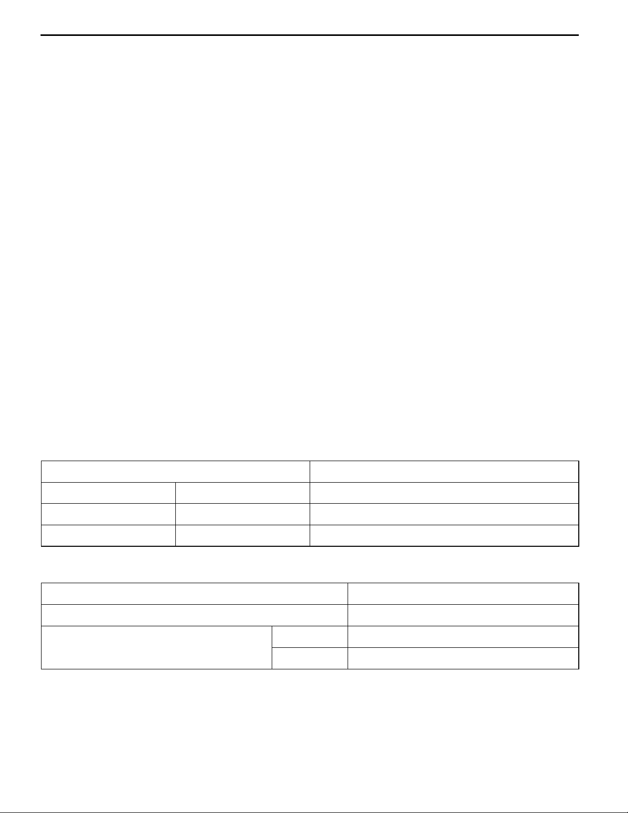
GENERAL SPECIFICATIONS
Items Specifications
Engine-ECU <M/T> Identification model No. E2T67693
Engine-A/T-ECU <A/T> Identification model No. E6T30571
Actuators Injector identification mark CDH240
SERVICE SPECIFICATIONS
Items Standard value
Oxygen sensor output voltage V 0.6 - 1.0
Oxygen sensor heater coil resistance (at 20_C) front 4.5 - 8.0
W
rear 11 - 18
Page 4

13A-4
MPI <4G6> -
TROUBLESHOOTING
DIAGNOSIS FUNCTION
ENGINE WARNING LAMP (CHECK ENGINE LAMP)
If an abnormality occurs in any of the following items related
to the MPI system, the engine warning lamp will illuminate
or flash. If the lamp remains illuminated or if the lamp
illuminates while the engine is running, check the diagnosis
Engine warning lamp
(check engine lamp)
Engine warning lamp inspection items
Code No. Diagnosis item
- Engine-ECU <M/T> or engine-A/T-ECU <A/T>
P0100 Air flow sensor system
P0105 Barometric pressure sensor system
code output.
However, the warning lamp will illuminate as bulb check for
five seconds whenever the ignition switch is turned to the
ON position.
Troubleshooting
P0110 Intake air temperature sensor system
P0115 Engine coolant temperature sensor system
P0120 Throttle position sensor system
P0125 Feedback system
P0130 Oxygen sensor (front) system <sensor 1>
P0135 Oxygen sensor heater (front) system <sensor 1>
P0136 Oxygen sensor (rear) system <sensor 2>
P0141 Oxygen sensor heater (rear) system <sensor 2>
P0170 Abnormal fuel system
P0201 No. 1 injector system
P0202 No. 2 injector system
P0203 No. 3 injector system
P0204 No. 4 injector system
P0300
Ignition coil (power transistor) system
L
P0301 No. 1 cylinder misfire detected
P0302 No. 2 cylinder misfire detected
P0303 No. 3 cylinder misfire detected
P0304 No. 4 cylinder misfire detected
P0335 Crank angle sensor system
P0340 Camshaft position sensor system
Page 5

MPI <4G6> -
MPI <4G6> -
Code No. Diagnosis item
P0403 EGR valve system
P0420 Catalyst malfunction
P0443 Purge control solenoid valve system
P0505 Idle speed control system
P0510 Idle position switch system
P0551 Power steering fluid pressure switch system
NOTE
1. If the engine warning lamp illuminates because of a malfunction of the engine-ECU <M/T> or
engine-A/T-ECU <A/T>, communication between MUT-IIand the engine-ECU <M/T> or engine-A/T-ECU
<A/T> is impossible. In this case, the diagnosis code cannot be read.
2. After the engine-ECU <M/T> or engine-A/T-ECU <A/T> has detected a malfunction, the engine warning
lamp illuminates when the engine is next turned on and the same malfunction is re-detected. However,
for items marked with a “L” in the diagnosis code number column, the engine warning lamp illuminates
only on the first detection of the malfunction.
3. After the engine warning lamp illuminates, it will be switched off under the following conditions.
(1) When the engine-ECU <M/T> or engine-A/T-ECU <A/T> monitored the power train malfunction
three times* and met set condition requirements, it detected no malfunction.
*: In this case, “one time” indicates from engine start to stop.
(2) For misfiring malfunction, when driving conditions (engine speed, engine coolant temperature,
etc.) are similar to those when the malfunction was first recorded.
4. Sensor 1 indicates the sensor mounted at a position closest to the engine, and sensor 2 indicates
the sensor mounted at the position second closest to the engine.
Troubleshooting
Troubleshooting
13A-5
METHOD OF READING AND ERASING DIAGNOSIS
CODES
Refer to GROUP 00 - How to Use Troubleshooting/Inspection
Service Points.
DIAGNOSIS USING DIAGNOSIS 2 MODE
1. Switch the diagnosis mode of the engine control unit
to DIAGNOSIS 2 mode using the MUT-II.
2. Carry out a road test.
3. Take a reading of the diagnosis code and repair the
problem location.
4. Turn the ignition switch to OFF and then back to ON
again.
NOTE
By turning the ignition switch to OFF, the ENGINE-ECU
will switch the diagnosis mode from DIAGNOSIS 2 mode
to DIAGNOSIS 1 mode.
5. Erase the diagnosis codes.
Page 6
13A-6
MPI <4G6> -
INSPECTION USING MUT-IIDATA LIST AND ACTUATOR
TESTING
1. Carry out inspection by means of the data list and the
2. After repairing, re-check using the MUT-IIand check that
3. Erase the diagnosis code memory.
4. Remove the MUT-II, and then start the engine again and
FREEZE FRAME DATA
When the engine-ECU <M/T> or engine-A/T-ECU <A/T>
detects a malfunction and stores a diagnosis code, it also
stores a current status of the engine. This function is called
“Freeze frame data.” By analyzing this “freeze frame” data
with the MUT-II, an effective troubleshooting can be
performed.
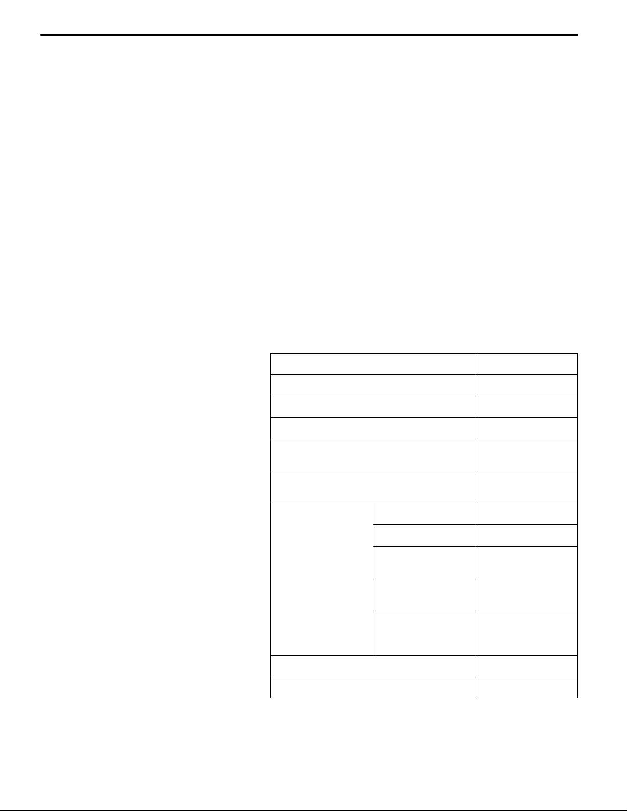
The display items of freeze frame data are shown below.
Troubleshooting
actuator test function. If there is an abnormality, check
and repair the chassis harnesses and components.
the abnormal input and output have returned to normal
as a result of the repairs.
carry out a road test to confirm that the problem has
disappeared.
Display item list
Data item Unit
Engine coolant temperature sensor _C
Engine speed r/min
Vehicle speed km/h
Long-term fuel compensation (long-term
fuel trim)
Short-term fuel compensation (short-term
fuel trim)
Fuel control condi- Open loop OL
tion
Closed loop CL
Open loop owing to
drive condition
Open loop owing to
system malfunction
Closed loop based
on one oxygen sensor
%
%
OL-DRV.
OL-SYS.
CL-H02S
Calculation load value %
Diagnosis code during data recording -
NOTE
If malfunctions have been detected in multiple systems, store
one malfunction only, which has been detected first.
Page 7

MPI <4G6> -
Troubleshooting
13A-7
READINESS TEST STATUS
The engine-ECU <M/T> or engine-A/T-ECU <A/T> monitors
the following main diagnosis items, judges if these items are
in good condition or not, and the stores its history. This
history can be read out by using MUT-II. (If the ECU has
judged a item before, the MUT-IIdisplays “Complete.”)
In addition, if diagnosis codes are erased or the battery
cable is disconnected, this history will also be erased (the
memory will be reset).
Catalyst: P0420
D
Oxygen sensor: P0130
D
Oxygen sensor heater: P0135, P0141
D
FAIL-SAFE FUNCTION REFERENCE TABLE
When the main sensor malfunctions are detected by the diagnosis function, the vehicle is controlled
by means of the pre-set control logic to maintain safe conditions for driving.
Malfunctioning item Control contents during malfunction
Air flow sensor 1. Uses the throttle position sensor signal and engine speed signal (crank angle sensor
signal) to take reading of the basic injector drive time and basic ignition timing from
the pre-set mapping.
2. Fixes the ISC servo in the appointed position so idle control is not performed.
Intake air temperature
sensor
Throttle position sensor (TPS)
Engine coolant temperature sensor
Camshaft position
sensor
Barometric pressure
sensor
Detonation sensor Switches the ignition timing from ignition timing for super petrol to ignition timing for standard
Ignition coil, power
transistor
Oxygen sensor (front) Air/fuel ratio feedback control (closed loop control) is not performed.
Controls as if the intake air temperature is 25_C.
No increase in fuel injection amount during acceleration due to the throttle position sensor
signal.
Controls as if the engine coolant temperature is 80_C.
Injects fuel to all cylinders simultaneously.
(However, after the ignition switch is turned to ON, the No. 1 cylinder top dead centre is not
detected at all.)
Controls as if the barometric pressure is 101 kPa.
petrol.
Cuts off the fuel supply to cylinders with an abnormal ignition.
Oxygen sensor (rear) Performs the feedback control (closed loop control) of the air/fuel ratio by using only the
signal of the oxygen sensor (front) installed on the front of the catalytic converter.
Alternator FR terminal Does not control the output of the alternator according to an electrical load. (works as a
normal alternator)
Misfiring If the detected misfiring causes damage to the catalyst, the misfiring cylinder will be shut
down.
Page 8
13A-8
MPI <4G6> -
Troubleshooting
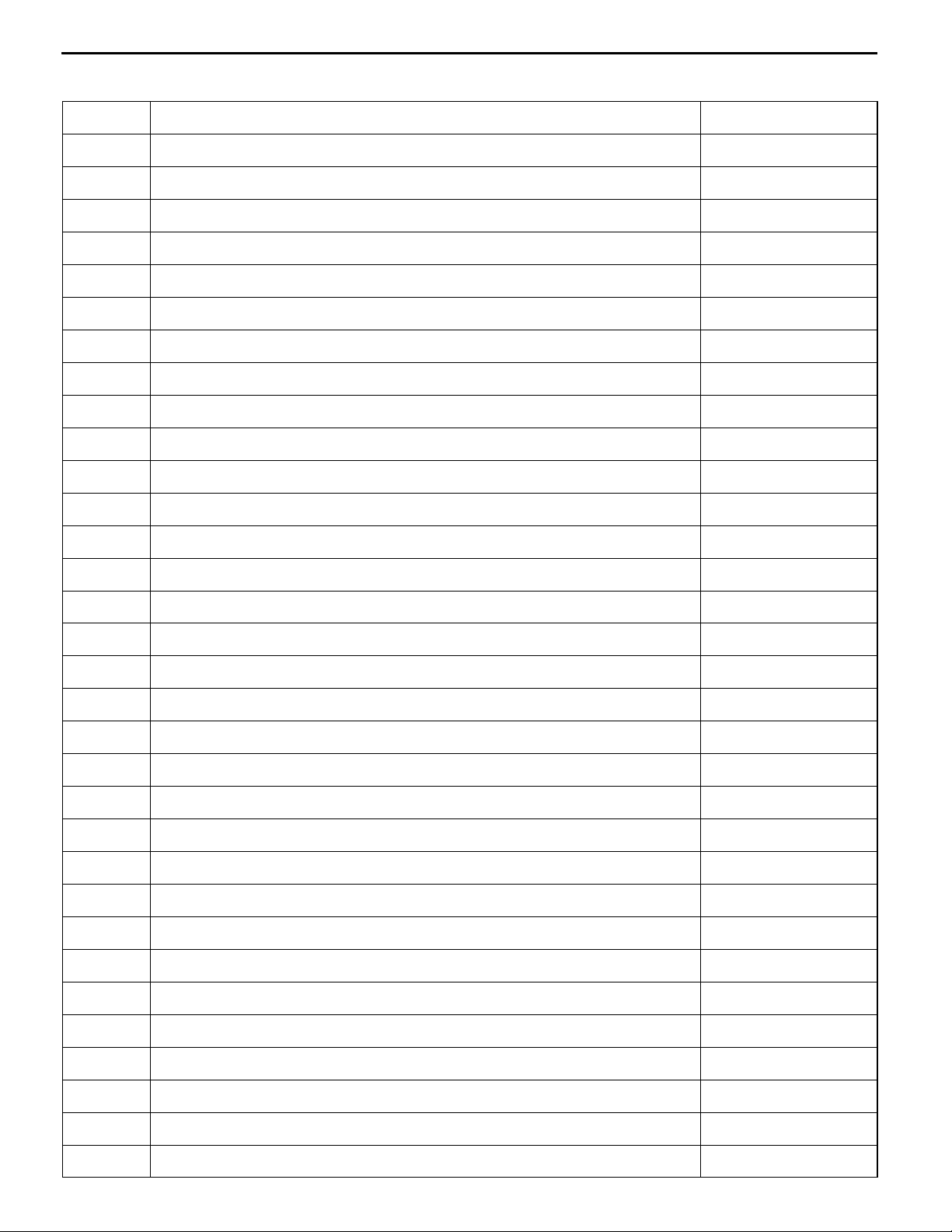
INSPECTION CHART FOR DIAGNOSIS CODES
Code No. Diagnosis item Reference page
P0100 Air flow sensor system 13A-10
P0105 Barometric pressure sensor system 13A-12
P0110 Intake air temperature sensor system 13A-14
P0115 Engine coolant temperature sensor system 13A-16
P0120 Throttle position sensor system 13A-18
P0125 Feedback system 13A-20
P0130 Oxygen sensor (front) system <sensor 1> 13A-21
P0135 Oxygen sensor heater (front) system <sensor 1> 13A-23
P0136 Oxygen sensor (rear) system <sensor 2> 13A-24
P0141 Oxygen sensor heater (rear) system <sensor 2> 13A-26
P0170 Abnormal fuel system 13A-27
P0201 No. 1 injector system 13A-28
P0202 No. 2 injector system 13A-28
P0203 No. 3 injector system 13A-28
P0204 No. 4 injector system 13A-28
P0300
P0301 No. 1 cylinder misfire detected 13A-31
P0302 No. 2 cylinder misfire detected 13A-31
P0303 No. 3 cylinder misfire detected 13A-31
P0304 No. 4 cylinder misfire detected 13A-31
P0325 Detonation sensor system 13A-32
P0335 Crank angle sensor system 13A-32
P0340 Camshaft position sensor system 13A-34
P0403 EGR valve system 13A-36
P0420 Catalyst malfunction 13A-37
Ignition coil (power transistor) system 13A-29
L
P0443 Purge control solenoid valve system 13A-38
P0500 Vehicle speed sensor system 13A-39
P0505 Idle speed control system 13A-39
P0510 Idle position switch system 13A-41
P0551 Power steering fluid pressure switch system 13A-42
P1500 Alternator FR terminal system 13A-43
P1610 Immobilizer system 13A-44
Page 9

MPI <4G6> -
NOTE
1. Do not replace the engine-ECU <M/T> or engine-A/T-ECU <A/T> until a through terminal check reveals
there are no short/open circuit.
2. Check that the engine-ECU <M/T> or engine-A/T-ECU <A/T> earth circuit is normal before checking
for the cause of the problem.
3. After the engine-ECU <M/T> or engine-A/T-ECU <A/T> has detected a malfunction, a diagnosis code
is recorded the next time the engine is started and the same malfunction is re-detected. However,
for items marked with a “L”, the diagnosis code is recorded on the first detection of the malfunction.
4. Sensor 1 indicates the sensor mounted at a position closest to the engine, and sensor 2 indicates
the sensor mounted at the position second closest to the engine.
Troubleshooting
13A-9
Page 10
13A-10
MPI <4G6> -
Troubleshooting
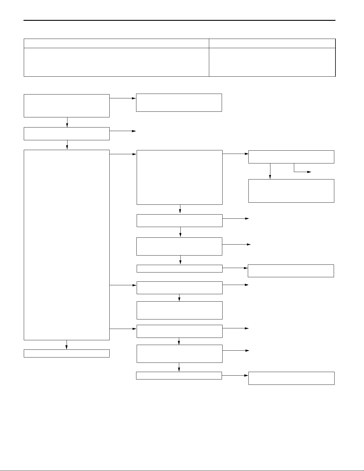
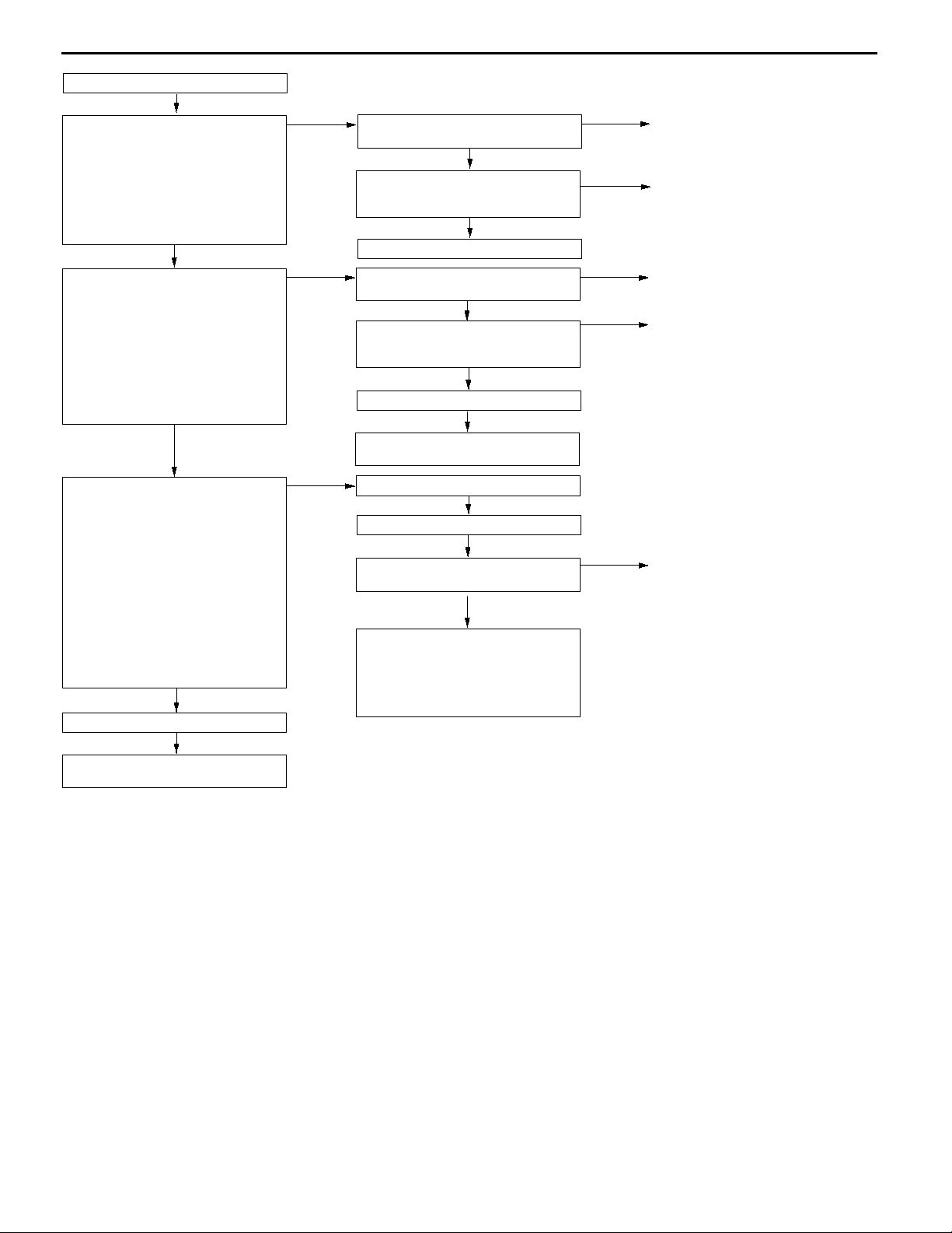
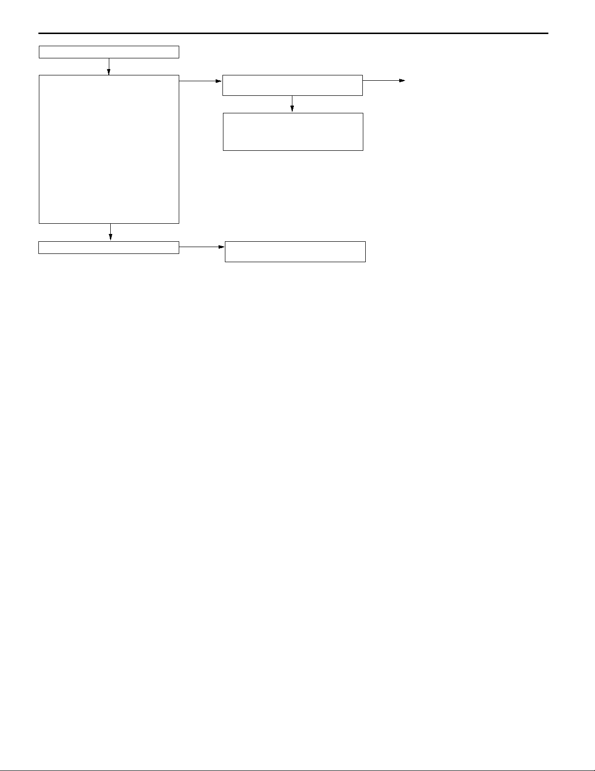
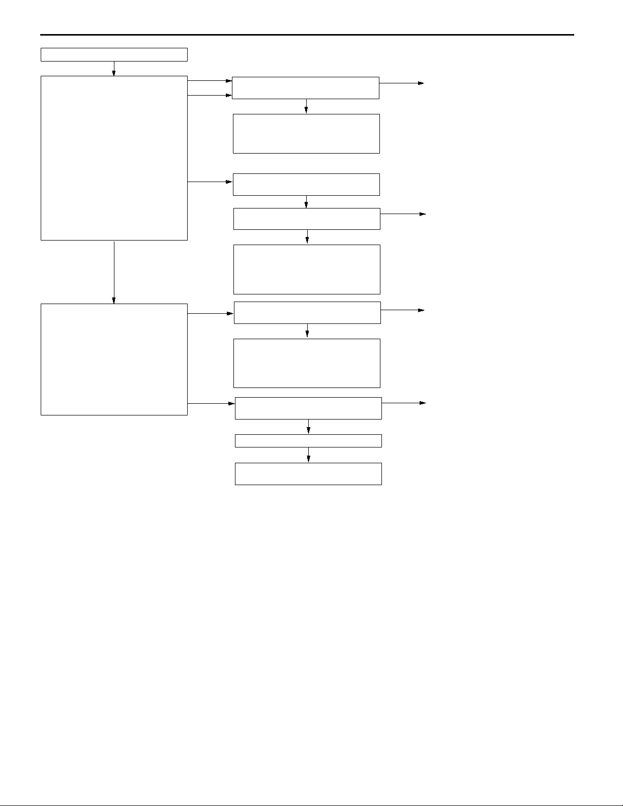
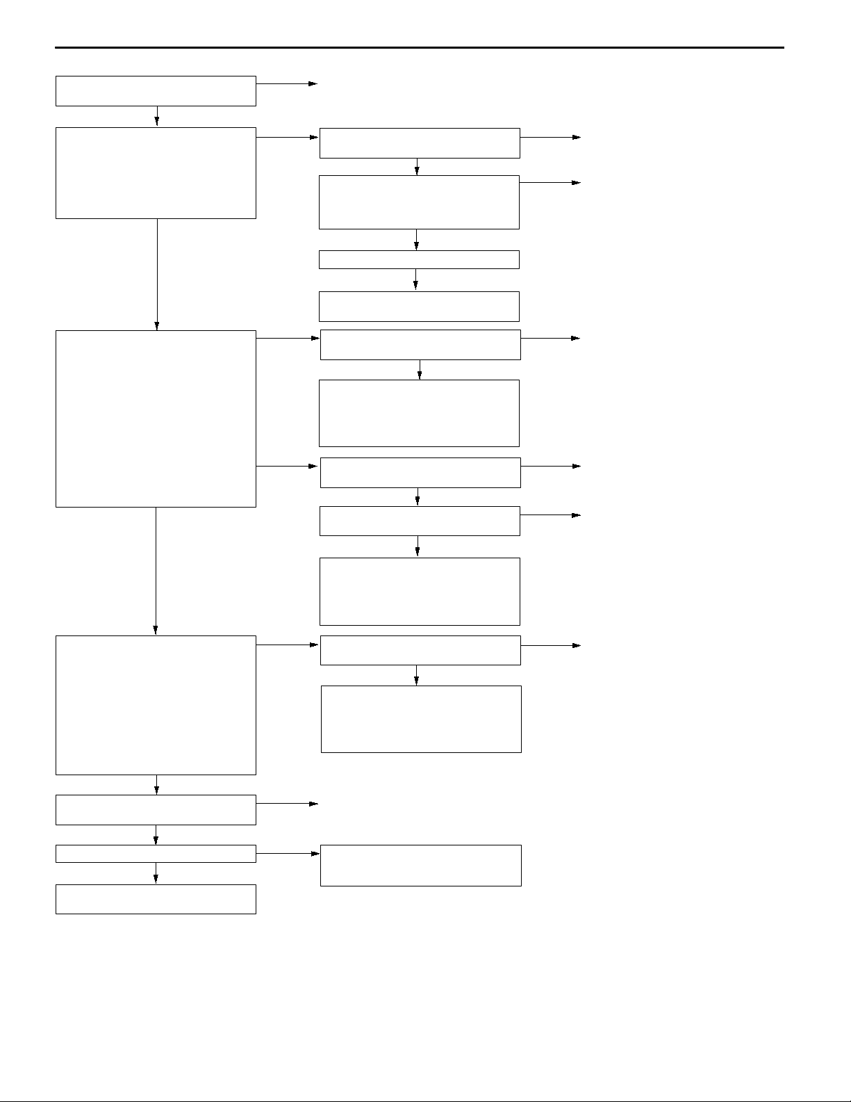
INSPECTION PROCEDURE CLASSIFIED BY DIAGNOSIS CODE
Code No. P0100 Air flow sensor system Probable cause
Range of Check
Engine speed: 500 r/min or more
D
Set Conditions
The sensor output frequency is 3.3 Hz or less for four seconds.
D
Malfunction of air flow sensor
D
Open or short circuit in air flow sensor circuit or
D
loose connector contact
Malfunction of engine-ECU <M/T>
D
Malfunction of engine-A/T-ECU <A/T>
D
MUT-IIData list
12 Air flow sensor (Refer to
P.13A-75, DATA LIST
REFERENCE TABLE.)
NG
Check the following connector:
B-12
OK
Measure at air flow sensor connector
B-12.
Disconnect the connector and
D
measure at the harness side.
(1) Voltage between terminal 3 and
earth (Ignition switch: ON)
OK:
(2) Voltage between terminal 4 and
(3) Resistance between terminal 5
To the next page
4.8 - 5.2 V
earth (Ignition switch: ON)
OK:
System voltage
and earth
OK:
2Wor less
OK
OK
NG
(1) NG
(2) NG
(3) NG
Transient malfunction
(Refer to GROUP 00 - Points to
Note for Intermittent Malfunctions.)
Repair
Measure at engine-ECU connector
C-40 <M/T> or engine-A/T-ECU
connector C-176 <A/T>.
Measure the voltage at the
D
engine-ECU terminal <M/T> or
engine-A/T-ECU terminal <A/T>.
Ignition switch: ON
D
Voltage between terminal 90
D
<M/T>, 65 <A/T> and earth
OK:
4.8 - 5.2 V
NG
Check the following connector:
C-40 <M/T>, C-176 <A/T>
OK
Check the harness between the air
flow sensor and the engine-ECU
<M/T> or engine-A/T-ECU <A/T>.
OK
Check the trouble symptoms.
Check the following connector:
C-31
OK
Check the harness between the air
flow sensor and the engine control
relay, and repair if necessary.
Check the following connectors:
C-40 <M/T>, C-176 <A/T>
OK
Check the harness between the air
flow sensor and the engine-ECU
<M/T> or engine-A/T-ECU <A/T>.
OK
Check the trouble symptoms.
OK
NG
NG
NG
NG
NG
NG
NG
Check the following connector:
C-40 <M/T>, C-176 <A/T>
OK
Check the harness between the air
flow sensor and the engine-ECU
<M/T> or engine-A/T-ECU <A/T>,
and repair if necessary.
Repair
Repair
Replace the engine-ECU <M/T> or
engine-A/T-ECU <A/T>.
Repair
Repair
Repair
Replace the engine-ECU <M/T> or
engine-A/T-ECU <A/T>.
NG
Repair
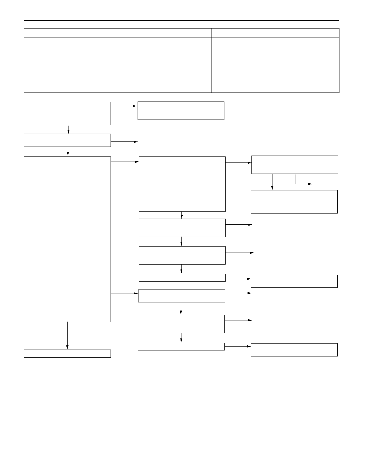
Page 11
From the previous page
OK
Measure at air flow sensor connector
B-12.
Use test harness (MB991709) to
D
connect the connector, and
measure at the pick-up harness.
Ignition switch: ON
D
Voltage between terminal 7 and
D
earth
OK:
7-8V
OK
Measure at air flow sensor connector
B-12.
Use test harness (MB991709) to
D
connect the connector, and
measure at the pick-up harness.
Voltage between terminal 7 and
D
earth
OK:
Engine: Idling
0-1V
Engine speed: 3,000 r/min
6-9V
OK
Measure the output waveform at air
flow sensor connector B-12 (by
using an analyzer).
Use test harness (MB991709) to
D
connect the connector, and
measure at the pick-up harness.
Engine: Idling
D
Voltage between terminal 3 and
D
earth
OK:
Waveforms should be displayed on P.13A-88 (Inspection Procedure Using
an Analyzer) and noise
should not be displayed in
the waveform.
OK
Check the trouble symptoms.
NG
Replace the engine-ECU <M/T> or
engine-A/T-ECU <A/T>.
MPI <4G6> -
NG
NG
NG
Check the following connector:
C-34 <M/T>, C-177 <A/T>
Check the harness between the air
flow sensor and the engine-ECU
<M/T> or engine-A/T-ECU <A/T>.
Replace the air flow sensor.
Check the following connector:
C-34 <M/T>, C-177 <A/T>
Check the harness between the air
flow sensor and the engine-ECU
<M/T> or engine-A/T-ECU <A/T>.
Check the trouble symptoms.
Replace the engine-ECU <M/T> or
engine-A/T-ECU <A/T>.
Replace the air flow sensor.
Check the trouble symptoms.
Check the following connectors:
C-40 <M/T>, C-176 <A/T>, C-31
Check the harnesses between the
air flow sensor and the engine-ECU
<M/T> or engine-A/T-ECU <A/T> and
between the air flow sensor and the
engine control relay, and repair if
necessary.
Troubleshooting
NG
OK
NG
OK
NG
OK
OK
NG
NG
OK
NG
NG
13A-11
Repair
Repair
Repair
Repair
Repair
Page 12
13A-12
MPI <4G6> -
Troubleshooting
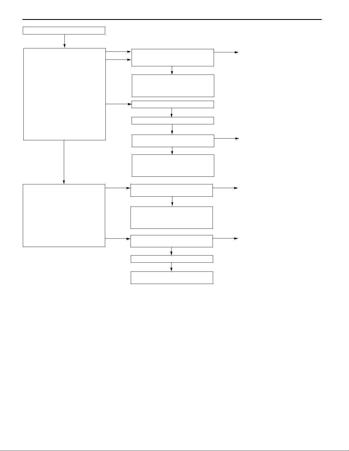
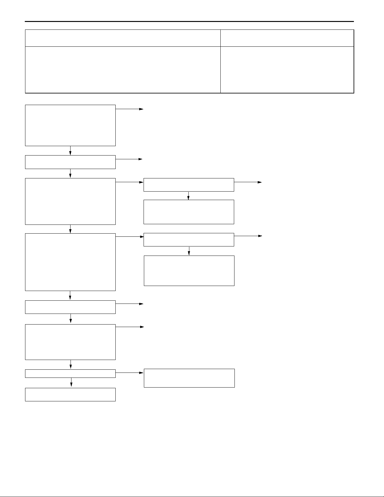
Code No. P0105 Barometric pressure sensor system Probable cause
Range of Check
Two seconds have passed since the ignition switch is turned ON or the
D
engine starting process is completed.
Battery voltage: 8 V or more
D
Set Conditions
The sensor output voltage is 4.5 V or more for four seconds (equivalent to
D
114 kPa of barometric pressure)
or
The sensor output voltage is 0.2 V or less (equivalent to 53 kPa of
D
barometric pressure)
Malfunction of barometric pressure sensor
D
Open or short circuit in barometric pressure
D
sensor circuit or loose connector contact
Malfunction of engine-ECU <M/T>
D
Malfunction of engine-A/T-ECU <A/T>
D
MUT-IIData list
25 Barometric pressure sensor
(Refer to P.13A-75, DATA LIST
REFERENCE TABLE.)
NG
Check the following connector:
B-12
OK
Measure at air flow sensor connector
B-12.
Disconnect the connector and
D
measure at the harness side.
(1) Voltage between terminal 1 and
earth (Ignition switch: ON)
OK:
(2) Resistance between terminal 5
4.8 - 5.2 V
and earth
OK:
2Wor less
OK
NG
(1) NG
(2) NG
Transient malfunction
(Refer to GROUP 00 - Points to
Note for Intermittent Malfunctions.)
Repair
Measure at engine-ECU connector
C-40 <M/T> or engine-A/T-ECU
connector C-176 <A/T>.
Measure the voltage at the
D
engine-ECU terminal <M/T> or
engine-A/T-ECU terminal <A/T>.
Ignition switch: ON
D
Voltage between terminal 81
D
<M/T>, 46 <A/T> and earth
OK:
4.8 - 5.2 V
NG
Check the following connectors:
C-40 <M/T>, C-176 <A/T>, C-47
<RHD>
OK
Check the harness between the air
flow sensor and the engine-ECU
<M/T> or engine-A/T-ECU <A/T>.
OK
Check the trouble symptoms.
Check the following connector:
C-40 <M/T>, C-176<A/T>
OK
NG
NG
NG
NG
OK
Check the following connectors:
C-40 <M/T>, C-176 <A/T>, C-47
<RHD>
OK
Check the harness between the air
flow sensor and the engine-ECU
<M/T> or engine-A/T-ECU <A/T>,
and repair if necessary.
Repair
Repair
Replace the engine-ECU <M/T> or
engine-A/T-ECU <A/T>.
Repair
NG
Repair
To the next page
OK
Check the harness between the air
flow sensor and the engine-ECU
<M/T> or engine-A/T-ECU <A/T>.
OK
Check the trouble symptoms.
NG
NG
Repair
Replace the engine-ECU <M/T> or
engine-A/T-ECU <A/T>.
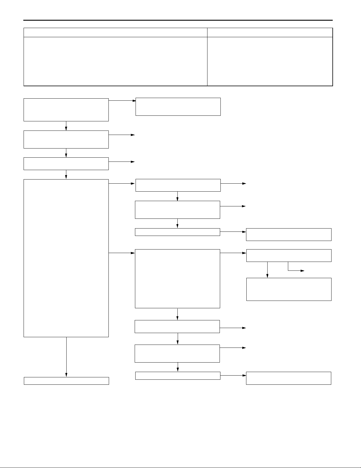
Page 13
From the previous page
OK
Measure at air flow sensor connector
B-12.
Connect connector terminals No.
D
1, No. 2 and No. 5 only by using
test harness (MB991709), and
measure at the pick-up harness.
Ignition switch: ON
D
(1) Voltage between terminal 1 and
earth
OK:
(2) Voltage between terminal 2 and
(3) Voltage between terminal 5 and
4.8 - 5.2 V
earth
OK:
Altitude 0 m: 3.7 - 4.3 V
Altitude 1,200 m:
3.2 - 3.8 V
earth
OK:
0.5 V or less
OK
MPI <4G6> -
(1) NG
(3) NG
(2) NG
Check the following connectors:
C-40 <M/T>, C-176 <A/T>, C-47
<RHD>
Check the harness between the air
flow sensor and the engine-ECU
<M/T> or engine-A/T-ECU <A/T>,
and repair if necessary.
Replace the air flow sensor.
Check the trouble symptoms.
Check the following connector:
C-40 <M/T>, C-176 <A/T>
Check the harness between the air
flow sensor and the engine-ECU
<M/T> or engine-A/T-ECU <A/T>,
and repair if necessary.
Troubleshooting
NG
OK
NG
NG
OK
13A-13
Repair
Repair
Measure at engine-ECU connector
C-40 <M/T> or engine-A/T-ECU
connector C-176 <A/T>.
Measure the voltage at the
D
engine-ECU terminal.
Ignition switch: ON
D
Voltage between terminal 85
D
<M/T>, 55 <A/T> and earth
OK:
Altitude 0 m: 3.7 - 4.3 V
Altitude 1,200 m:
3.2 - 3.8 V
NG
OK
Check the following connector:
C-40 <M/T>, C-176 <A/T>
OK
Check the harness between the air
flow sensor and the engine-ECU
<M/T> or engine-A/T-ECU <A/T>,
and repair if necessary.
Check the following connector:
C-40 <M/T>, C-176 <A/T>
OK
Check the trouble symptoms.
NG
Replace the engine-ECU <M/T> or
engine-A/T-ECU <A/T>.
NG
NG
Repair
Repair
Page 14
13A-14
MPI <4G6> -
Troubleshooting
Code No. P0110 Intake air temperature sensor system Probable cause
Range of Check
Two seconds have passed since the ignition switch is turned ON or the
D
engine starting process is completed.
Set Conditions
The sensor output voltage is 4.6 V or more for four seconds (equivalent to
D
-45_C of intake air temperature)
or
The sensor output voltage is 0.2 V or more for four seconds (equivalent to
D
125_C of intake air temperature)
Malfunction of intake air temperature sensor
D
Open or short circuit in intake air temperature
D
sensor or loose connector contact
Malfunction of engine-ECU <M/T>
D
Malfunction of engine-A/T-ECU <A/T>
D
MUT-IIData list
13 Intake air temperature sensor
OK:
Roughly the same as ambient temperature.
NG
Check the intake air temperature
sensor itself.
(Refer to P.13A-90*.)
OK
Check the following connector:
B-12
OK
Measure at air flow sensor connector
B-12.
Disconnect the connector and
D
measure at the harness side.
(1) Resistance between terminal 5
and earth
OK:
(2) Voltage between terminal 6 and
2Wor less
earth
(Ignition switch: ON)
OK:
4.8 - 5.2 V
OK
NG
NG
(1) NG
(2) NG
Transient malfunction
(Refer to GROUP 00 - Points to
Note for Intermittent Malfunctions.)
Repair
Repair
Check the following connector:
C-40 <M/T>, C-176 <A/T>
OK
Check the harness between the air
flow sensor and the engine-ECU
<M/T> or engine-A/T-ECU <A/T>.
OK
Check the trouble symptoms.
Measure at engine-ECU connector
C-40 <M/T> or engine-A/T-ECU
connector C-176 <A/T>.
Measure the voltage at the
D
engine-ECU terminal <M/T> or
engine-A/T-ECU terminal <A/T>.
Disconnect connector B-12.
D
Ignition switch: ON
D
Voltage between terminal 62
D
<M/T>, 64 <A/T> and earth
OK:
4.8 - 5.2 V
NG
NG
NG
NG
OK
Repair
Repair
Replace the engine-ECU <M/T> or
engine-A/T-ECU <A/T>.
Check the following connector:
C-40 <M/T>, C-176 <A/T>
OK
Check the harness between the air
flow sensor and the engine-ECU
<M/T> or engine-A/T-ECU <A/T>,
and repair if necessary.
NG
Repair
Check the following connector:
C-40 <M/T>, C-176 <A/T>
OK
OK
Check the harness between the air
flow sensor and the engine-ECU
<M/T> or engine-A/T-ECU <A/T>.
OK
Check the trouble symptoms.
To the next page
NG
NG
NG
NOTE:
*: Refer to the ’97 GALANT Workshop Manual (Pub. No. PWDE9611)
Repair
Repair
Replace the engine-ECU <M/T> or
engine-A/T-ECU <A/T>.
Page 15
From the previous page
OK
Measure at air flow sensor connector
B-12.
Use the test harness (MB991709)
D
to connect only terminals 5 and
6, and then measure at the
pick-up harness.
Ignition switch: ON
D
Voltage between terminal 6 and
D
earth
OK:
Ambient temperature 0_C:
3.2 - 3.8 V
Ambient temperature 20_C:
2.3 - 2.9 V
Ambient temperature 40_C:
1.5 - 2.1 V
Ambient temperature 80_C:
0.4 - 1.0 V
OK
Check the trouble symptoms.
MPI <4G6> -
NG
NG
Check the following connector:
C-40 <M/T>, C-176 <A/T>
Check the harness between the air
flow sensor and the engine-ECU
<M/T> or engine-A/T-ECU <A/T>,
and repair if necessary.
Replace the engine-ECU <M/T> or
engine-A/T-ECU <A/T>.
Troubleshooting
NG
OK
13A-15
Repair
Page 16
13A-16
MPI <4G6> -
MPI <4G6> -
Troubleshooting
Troubleshooting
Code No. P0115 Engine coolant temperature sensor
system
Range of Check
Engine: Two seconds after the engine has been started
D
Set Conditions
The sensor output voltage is 4.6 V or more for four seconds (equivalent to
D
-45_C or lower of engine coolant temperature)
or
The sensor output voltage is 0.1 V or less for four seconds (equivalent to
D
140_C or higher of engine coolant temperature)
Range of Check
Engine: After starting
D
Set Conditions
The engine coolant temperature has reduced from over 40_C to less than
D
40_C, and that condition has lasted for five minutes or more.
MUT-IIData list
21 Engine coolant temperature
sensor
OK:
When the engine is cold,
the temperature is roughly
the same as ambient temperature. If warm, it is 80 120_C.
NG
Measure at engine coolant
temperature sensor connector B-33.
Disconnect the connector and
D
measure at the harness side.
Resistance between terminals 1
D
and 2
OK:
At 20_C of engine coolant
temperature: 2.1 - 2.7 k
At 80_C of engine coolant
temperature: 0.26 - 0.36
k
W
OK
OK
NG
W
Transient malfunction
(Refer to GROUP 00 - Points to
Note for Intermittent Malfunctions.)
Replace
Probable cause
Malfunction of engine coolant temperature sensor
D
Open or short circuit in the engine coolant
D
temperature sensor circuit or loose connector
contact
Malfunction of engine-ECU <M/T>
D
Malfunction of engine-A/T-ECU <A/T>
D
Check the following connector:
B-33
OK
To the next page
NG
Repair
Page 17
From the previous page
OK
Measure at engine coolant
temperature sensor connector B-33.
Disconnect the connector and
D
measure at the harness side.
(1) Voltage between terminal 1 and
earth
(Ignition switch: ON)
OK:
(2) Resistance between terminal 2
Measure at engine coolant
temperature sensor connector B-33.
D
D
D
Check the trouble symptoms.
4.8 - 5.2 V
and earth
OK:
2Wor less
OK
Use test harness (MB991658) to
connect the connector, and
measure at the pick-up harness.
Ignition switch: ON
Voltage between terminal 1 and
earth
OK:
At 0_C of engine coolant
temperature: 3.2 - 3.8 V
At 20_C of engine coolant
temperature: 2.3 - 2.9 V
At 40_C of engine coolant
temperature: 1.3 - 1.9 V
At 80_C of engine coolant
temperature: 0.3 - 0.9 V
OK
MPI <4G6> -
(1) NG
(2) NG
NG
NG
Measure at engine-ECU connector
C-40 <M/T> or engine-A/T-ECU
connector C-176 <A/T>.
D
D
D
D
Check the following connector:
C-40 <M/T>, C-176 <A/T>
Check the harness wire between the
engine coolant temperature sensor
and the engine-ECU <M/T> or
engine-A/T-ECU <A/T>.
Check the trouble symptoms.
Check the following connector:
C-40 <M/T>, C-176 <A/T>
Check the harness wire between the
engine coolant temperature sensor
and the engine-ECU <M/T> or
engine-A/T-ECU <A/T>.
Check the trouble symptoms.
Check the following connector:
C-40 <M/T>, C-176 <A/T>
Troubleshooting
Measure the voltage at the
engine-ECU terminal <M/T> or
engine-A/T-ECU terminal <A/T>.
Disconnect connector B-33.
Ignition switch: ON
Voltage between terminal 83
<M/T>, 44 <A/T> and earth
OK:
4.8 - 5.2 V
NG
OK
OK
OK
OK
Check the engine coolant
temperature sensor.
(Refer to P.13A-90*.)
OK
OK
Check the harness wire between the
engine coolant temperature sensor
and the engine-ECU <M/T> or
engine-A/T-ECU <A/T>, and repair if
necessary.
Replace the engine-ECU <M/T> or
engine-A/T-ECU <A/T>.
NG
NG
NG
NG
NG
OK
NG
NG
NG
13A-17
Check the following connector:
C-40 <M/T>, C-176 <A/T>
OK
Check the harness wire between the
engine coolant temperature sensor
and the engine-ECU <M/T> or
engine-A/T-ECU <A/T>, and repair if
necessary.
Repair
Repair
Replace the engine-ECU <M/T> or
engine-A/T-ECU <A/T>.
Repair
Repair
Replace the engine-ECU <M/T> or
engine-A/T-ECU <A/T>.
Repair
Repair
NG
Repair
NOTE:
*: Refer to the ’97 GALANT Workshop Manual (Pub. No. PWDE9611)
Page 18
13A-18
MPI <4G6> -
Troubleshooting
Code No. P0120 Throttle position sensor system Probable cause
Range of Check
Excluding two seconds after the ignition switch is turned ON or immediately
D
after the engine starts.
Set Conditions
When the idle position switch is ON, the sensor output voltage is 2 V or
D
more for 4 seconds
or
The sensor output voltage is 0.2 V or less for 4 seconds
D
Malfunction of throttle position sensor
D
Improper connector contact, open circuit or
D
short-circuited harness wire
Improper “ON” state of idle position switch
D
Short circuit of the idle position switch signal line
D
Malfunction of engine-ECU <M/T>
D
Malfunction of engine-A/T-ECU <A/T>
D
MUT-IIData list
14 Throttle position sensor
(Refer to P.13A-75, DATA LIST
REFERENCE TABLE.)
NG
Check the throttle position sensor.
(Refer to P.13A-91*.)
OK
Check the following connector:
B-07
OK
Measure at throttle position sensor
connector B-07.
Disconnect the connector and
D
measure at the harness side.
(1) Voltage between terminal 1 and
earth
(Ignition switch: ON)
OK:
(2) Resistance between terminal 4
To the next page
4.8 - 5.2 V
and earth
OK:
2Wor less
OK
OK
NG
NG
(1) NG
(2) NG
Transient malfunction
(Refer to GROUP 00 - Points to
Note for Intermittent Malfunctions.)
Replace
Repair
Measure at engine-ECU connector
C-40 <M/T> or engine-A/T-ECU
connector C-176 <A/T>.
Measure the voltage at the
D
engine-ECU <M/T> or
engine-A/T-ECU <A/T> connector
terminals.
Ignition switch: ON
D
Voltage between terminal 81 and
D
earth
OK:
4.8 - 5.2 V
NG
Check the following connector:
C-40 <M/T>, C-176 <A/T>
OK
Check the harness wire between the
throttle position sensor and the
engine-ECU <M/T> or
engine-A/T-ECU <A/T>.
OK
Check the trouble symptoms.
Check the following connector:
C-40 <M/T>, C-176 <A/T>
OK
Check the harness wire between the
throttle position sensor and the
engine-ECU <M/T> or
engine-A/T-ECU <A/T>.
OK
Check the trouble symptoms.
OK
NG
NG
NG
NG
NG
NG
Check the following connector:
C-40 <M/T>, C-176 <A/T>
OK
Check the harness wire between the
throttle position sensor and the
engine-ECU <M/T> or
engine-A/T-ECU <A/T>, and repair if
necessary.
Repair
Repair
Replace the engine-ECU <M/T> or
engine-A/T-ECU <A/T>.
Repair
Repair
Replace the engine-ECU <M/T> or
engine-A/T-ECU <A/T>.
NG
Repair
NOTE:
*: Refer to the ’97 GALANT Workshop Manual (Pub. No. PWDE9611)
Page 19
From the previous page
OK
Measure at throttle position sensor
connector B-07.
Use test harness (MB991536) to
D
connect the connector, and
measure at the pick-up harness.
Ignition switch: ON
D
(1) Voltage between terminal 1 and
earth
OK:
(2) Voltage between terminal 4 and
(3) Voltage between terminal 2 and
Measure at engine-ECU connector
C-40 <M/T> or engine-A/T-ECU
connector C-175 <A/T>.
D
D
D
4.8 - 5.2 V
earth
OK:
0.5 V or less
earth
OK:
Accelerator pedal fully released: 0.3 - 1.0 V
Accelerator pedal fully depressed: 4.5 - 5.5 V
OK
Measure voltage at the
engine-ECU terminal.
Ignition switch: ON
Voltage between terminal 84
<M/T>, 78 <A/T> and earth
OK:
Accelerator pedal fully released: 0.3 - 1.0 V
Accelerator pedal fully depressed: 4.5 - 5.5 V
MPI <4G6> -
(1) NG
(2) NG
(3) NG
NG
OK
Check the following connector:
C-40 <M/T>, C-176 <A/T>
Check the harness wire between the
throttle position sensor and the
engine-ECU <M/T> or
engine-A/T-ECU <A/T>.
Adjust the throttle position sensor.
(Refer to P.13A-81*.)
Check the following connector:
C-40 <M/T>, C-175 <A/T>
Check the harness wire between the
throttle position sensor and the
engine-ECU <M/T> or
engine-A/T-ECU <A/T>, and repair if
necessary.
Check the following connector:
C-40 <M/T>, C-175 <A/T>
Check the harness wire between the
throttle position sensor and the
engine-ECU <M/T> or
engine-A/T-ECU <A/T>, and repair if
necessary.
Check the following connector:
C-40 <M/T>, C-175<A/T>
Check the trouble symptoms.
Replace the engine-ECU <M/T> or
engine-A/T-ECU <A/T>.
Troubleshooting
NG
OK
NG
OK
NG
OK
NG
OK
NG
13A-19
Repair
Repair
Repair
Repair
NOTE:
*: Refer to the ’97 GALANT Workshop Manual (Pub. No. PWDE9611)
Page 20
13A-20
MPI <4G6> -
Troubleshooting
Code No. P0125 Feedback system Probable cause
Range of Check
The engine coolant temperature is approx. 80_C or more.
D
During stoichiometric feedback control
D
The vehicle is not being decelerated.
D
Set Conditions
Oxygen sensor (front) output voltage has been higher or lower than 0.5 V for
D
at least thirty seconds.
Malfunction of oxygen sensor (front)
D
Open or short circuit in the oxygen sensor (front)
D
circuit or loose connector contact
Malfunction of engine-ECU <M/T>
D
Malfunction of engine-A/T-ECU <A/T>
D
Check the following connector:
C-46
OK
Measure at oxygen sensor (front)
connector C-46.
Disconnect the connector and
D
measure at the harness side.
Resistance between terminal 2
D
and earth
OK:
2Wor less
OK
Measure at oxygen sensor (front)
connector C-46.
Measure the voltage at the
D
oxygen sensor (front) terminal
Engine: 2,500 r/min (after
D
warming up)
(1) Voltage between terminal 2 and
earth
OK:
(2) Voltage between terminal 1 and
Measure at engine-ECU connector
C-40 <M/T> or engine-A/T-ECU
connector C-175 <A/T>.
D
D
D
Check the following connector:
C-40 <M/T>, C-175 <A/T>
Check the trouble symptoms.
Replace the engine-ECU <M/T> or
engine-A/T-ECU <A/T>.
0.5 V or less
earth
OK:
0 V and 0.8 V alternate.
OK
Measure the voltage at the
engine-ECU terminal <M/T> or
engine-A/T-ECU terminal <A/T>.
Engine: 2,500 r/min (after
warming up)
Voltage between terminal 76
<M/T>, 71 <A/T> and earth
OK:
0 V and 0.8 V alternate.
OK
OK
NG
NG
NG
(1) NG
(2) NG
NG
NG
OK
Repair
Check the following connector:
C-40 <M/T>, C-176 <A/T>
OK
Check the harness wire between the
oxygen sensor (front) and the
engine-ECU <M/T> or
engine-A/T-ECU <A/T>.
OK
Check the trouble symptoms.
NG
Replace the engine-ECU <M/T> or
engine-A/T-ECU <A/T>.
Check the following connector:
C-40 <M/T>, C-176 <A/T>
OK
Check the harness wire between the
oxygen sensor (front) and the
engine-ECU <M/T> or
engine-A/T-ECU <A/T>, and repair if
necessary.
Check the oxygen sensor (front).
(Refer to P.13A-89.)
OK
Check the following connector:
C-40 <M/T>, C-175 <A/T>
OK
Check the harness wire between the
oxygen sensor (front) and the
engine-ECU <M/T> or
engine-A/T-ECU <A/T>, and repair if
necessary.
Check the following connector:
C-40 <M/T>, C-175 <A/T>
OK
Check the harness wire between the
oxygen sensor (front) and the
engine-ECU <M/T> or
engine-A/T-ECU <A/T>, and repair if
necessary.
Repair
Transient malfunction
(Refer to GROUP 00 - Points to
Note for Intermittent Malfunctions.)
NG
NG
NG
NG
NG
NG
Repair
Repair
Repair
Replace
Repair
Repair
Page 21

MPI <4G6> -
Troubleshooting
13A-21
Code No. P0130 Oxygen sensor (front) system <sensor
1>
Range of Check
Three minutes have been passed since the engine has been started.
D
The engine coolant temperature is approx. 80_C or more.
D
Engine speed is 1,200 r/min or more
D
Driving on a level surface at constant speed.
D
Set Conditions
The oxygen sensor (front) output voltage is 4.5 V or more when the sensor
D
output voltage is 0.2 V or less and a voltage of 5 V is applied to the oxygen
sensor (front) inside the engine-ECU.
Range of Check
Engine speed is 2,800 r/min or less
D
During driving
D
During air/fuel ratio feedback control
D
Set Conditions
The oxygen sensor (front) output frequency is s ix or less per 10 seconds on
D
average.
Probable cause
Malfunction of oxygen sensor (front)
D
Open or short circuit in the oxygen sensor (front)
D
circuit or loose connector contact
Malfunction of engine-ECU <M/T>
D
Malfunction of engine-A/T-ECU <A/T>
D
Page 22
13A-22
MPI <4G6> -
Troubleshooting
Check the following connector:
C-46
OK
Measure at oxygen sensor (front)
connector C-46.
Disconnect the connector and
D
measure at the harness side.
Resistance between terminal 2
D
and earth
OK:
2Wor less
OK
Measure at oxygen sensor (front)
connector C-46.
Measure the voltage at the
D
oxygen sensor (front) terminal.
Engine: 2,500 r/min (after
D
warming up)
(1) Voltage between terminal 2 and
earth
OK:
(2) Voltage between terminal 1 and
Measure at engine-ECU connector
C-40 <M/T> or engine-A/T-ECU
connector C-175 <A/T>.
D
D
D
Check the following connector:
C-40 <M/T>, C-175 <A/T>
Check the trouble symptoms.
Replace the engine-ECU <M/T> or
engine-A/T-ECU <A/T>.
0.5 V or less
earth
OK:
0 V and 0.8 V alternate.
OK
Measure the voltage at the
engine-ECU terminal.
Engine: 2,500 r/min (after
warming up)
Voltage between terminal 76
<M/T>, 71 <A/T> and earth
OK:
0 V and 0.8 V alternate.
OK
OK
NG
NG
NG
(1) NG
(2) NG
NG
NG
OK
Repair
Check the following connector:
C-40 <M/T>, C-176 <A/T>
OK
Check the harness wire between the
oxygen sensor (front) and the
engine-ECU <M/T> or
engine-A/T-ECU <A/T>.
OK
Check the trouble symptoms.
NG
Replace the engine-ECU <M/T> or
engine-A/T-ECU <A/T>.
Check the following connector:
C-40 <M/T>, C-176 <A/T>
OK
Check the harness wire between the
oxygen sensor (front) and the
engine-ECU <M/T> or
engine-A/T-ECU <A/T>, and repair if
necessary.
Check the oxygen sensor (front).
(Refer to P.13A-89.)
OK
Check the following connector:
C-40 <M/T>, C-175 <A/T>
OK
Check the harness wire between the
oxygen sensor (front) and the
engine-ECU <M/T> or
engine-A/T-ECU <A/T>, and repair if
necessary.
Check the following connector:
C-40 <M/T>, C-175 <A/T>
OK
Check the harness wire between the
oxygen sensor (front) and the
engine-ECU <M/T> or
engine-A/T-ECU <A/T>, and repair if
necessary.
Repair
Transient malfunction
(Refer to GROUP 00 - Points to
Note for Intermittent Malfunctions.)
NG
NG
NG
NG
NG
NG
Repair
Repair
Repair
Replace
Repair
Repair
Page 23
MPI <4G6> -
Troubleshooting
13A-23
Code No. P0135 Oxygen sensor heater (front) system
<sensor 1>
Range of Check
The engine coolant temperature is approx. 20_C or more.
D
The oxygen sensor heater (front) remains on.
D
The engine speed is 50 r/min or more.
D
Battery voltage is 11 - 16 V.
D
Set Conditions
The current, which flows through the oxygen sensor heater (front), is 0.2 A
D
or less or 3.5 A or more for six seconds.
Measure at oxygen sensor (front)
connector C-46.
Disconnect the connector and
D
measure at the harness side.
Resistance between terminals 3
D
and 4
OK:
4.5 - 8.0
Check the following connector:
C-46
Measure at oxygen sensor (front)
connector C-46.
Disconnect the connector and
D
measure at the harness side.
Ignition switch: ON
D
Voltage between terminal 3 and
D
earth
OK:
System voltage
Measure at engine-ECU connector
C-38 <M/T> or engine-A/T-ECU
connector C-177 <A/T>.
Measure the voltage at the
D
engine-ECU terminal.
Ignition switch: ON
D
Voltage between terminal 60
D
<M/T>, 3 <A/T> and earth
OK:
System voltage
Check the following connector:
C-38 <M/T>, C-177 <A/T>
Check the harness wires between
the oxygen sensor (front) and the
engine-ECU <M/T> or
engine-A/T-ECU <A/T> and between
the oxygen sensor (front) and the
engine control relay.
Check the trouble symptoms.
Replace the engine-ECU <M/T> or
engine-A/T-ECU <A/T>.
W
OK
OK
OK
OK
OK
OK
NG
NG
NG
NG
NG
NG
NG
OK
Replace
Repair
Check the following connector:
C-31
OK
Check the harness wires between
the oxygen sensor (front) and the
engine control relay, and repair if
necessary.
Check the following connector:
C-38 <M/T>, C-177 <A/T>
OK
Check the harness wire between the
oxygen sensor (front) and the
engine-ECU <M/T> or
engine-A/T-ECU <A/T>, and repair if
necessary.
Repair
Repair
Transient malfunction
(Refer to GROUP 00 - Points to
Note for Intermittent Malfunctions.)
Probable cause
Malfunction of oxygen sensor heater (front)
D
Open or short circuit in the oxygen sensor heater
D
(front) circuit or loose connector contact
Malfunction of engine-ECU <M/T>
D
Malfunction of engine-A/T-ECU <A/T>
D
NG
NG
Repair
Repair
Page 24

13A-24
MPI <4G6> -
Troubleshooting
Code No. P0136 Oxygen sensor (rear) system <sensor
2>
Range of Check
Three minutes have been passed since the engine has been started.
D
The engine coolant temperature is approx. 80_C or more.
D
Engine speed is 1,200 r/min or more
D
Driving on a level surface at constant speed.
D
Set Conditions
The oxygen sensor (rear) output voltage is 4.5 V or more when the sensor
D
output voltage is 0.2 V or less and a voltage of 5 V is applied to the oxygen
sensor (rear) inside the engine-ECU <M/T> or engine-A/T-ECU <A/T>.
Probable cause
Malfunction of oxygen sensor (rear)
D
Open or short circuit in the oxygen sensor (rear)
D
circuit or loose connector contact
Malfunction of engine-ECU <M/T>
D
Malfunction of engine-A/T-ECU <A/T>
D
Page 25
MPI <4G6> -
Troubleshooting
13A-25
Check the following connector:
C-85
OK
Measure at oxygen sensor (rear)
connector C-85.
Disconnect the connector and
D
measure at the harness side.
Resistance between terminal 2
D
and earth
OK:
2Wor less
OK
Measure at oxygen sensor (rear)
connector C-85.
Measure the voltage at the
D
oxygen sensor (rear) terminal.
Engine: 2,500 r/min (after
D
warming up)
(1) Voltage between terminal 2 and
earth
OK:
(2) Voltage between terminal 1 and
Measure at engine-ECU connector
C-40 <M/T> or engine-A/T-ECU
connector C-175 <A/T>.
D
D
D
Check the following connector:
C-40 <M/T>, C-175 <A/T>
Check the trouble symptoms.
Replace the engine-ECU <M/T> or
engine-A/T-ECU <A/T>.
0.5 V or less
earth
OK:
0 V and 0.8 V alternate.
OK
Measure the voltage at the
engine-ECU terminal <M/T> or
engine-A/T-ECU terminal <A/T>.
Engine: 2,500 r/min (after
warming up)
Voltage between terminal 75
<M/T>, 73 <A/T> and earth
OK:
0 V and 0.8 V alternate.
OK
OK
NG
NG
NG
(1) NG
(2) NG
NG
NG
OK
Repair
Check the following connector:
C-40 <M/T>, C-176 <A/T>
OK
Check the harness wire between the
oxygen sensor (rear) and the
engine-ECU <M/T> or
engine-A/T-ECU <A/T>.
OK
Check the trouble symptoms.
NG
Replace the engine-ECU <M/T> or
engine-A/T-ECU <A/T>.
Check the following connector:
C-40 <M/T>, C-176 <A/T>
OK
Check the harness wire between the
oxygen sensor (rear) and the
engine-ECU <M/T> or
engine-A/T-ECU <A/T>, and repair if
necessary.
Check the oxygen sensor (rear).
(Refer to P.13A-90.)
OK
Check the following connectors:
C-40 <M/T>, C-175 <A/T>
OK
Check the harness wire between the
oxygen sensor (rear) and the
engine-ECU <M/T> or
engine-A/T-ECU <A/T>, and repair if
necessary.
Check the following connector:
C-40 <M/T>, C-175 <A/T>
OK
Check the harness wire between the
oxygen sensor (rear) and the
engine-ECU <M/T> or
engine-A/T-ECU <A/T>, and repair if
necessary.
Repair
Transient malfunction
(Refer to GROUP 00 - Points to
Note for Intermittent Malfunctions.)
NG
NG
NG
NG
NG
NG
Repair
Repair
Repair
Replace
Repair
Repair
Page 26
13A-26
MPI <4G6> -
Troubleshooting
Code No. P0141 Oxygen sensor heater (rear) system
<sensor 2>
Range of Check
The engine coolant temperature is approx. 20_C or more.
D
The oxygen sensor heater (rear) remains on.
D
The engine speed is 50 r/min or more.
D
Battery voltage is 11 - 16 V.
D
Set Conditions
The current, which flows through the oxygen sensor heater (rear), is 0.2 A or
D
less or 3.5 A or more for six seconds.
Measure at oxygen sensor (rear)
connector C-85.
Disconnect the connector and
D
measure at the harness side.
Resistance between terminals 3
D
and 4
OK:
11 - 18
Check the following connector:
C-85
Measure at oxygen sensor (rear)
connector C-85.
Disconnect the connector and
D
measure at the harness side.
Ignition switch: ON
D
Voltage between terminal 3 and
D
earth
OK:
System voltage
Measure at engine-ECU connector
C-38 <M/T> or engine-A/T-ECU
connector C-177 <A/T>.
Measure the voltage at the
D
engine-ECU terminal <M/T> or
engine-A/T-ECU terminal <A/T>.
Ignition switch: ON
D
Voltage between terminal 54
D
<M/T>, 26 <A/T> and earth
OK:
System voltage
Check the following connector:
C-38 <M/T>, C-177 <A/T>
Check the harness wires between
the oxygen sensor (rear) and the
engine-ECU <M/T> or
engine-A/T-ECU <A/T> and between
the oxygen sensor (rear) and the
engine control relay.
Check the trouble symptoms.
Replace the engine-ECU <M/T> or
engine-A/T-ECU <A/T>.
W
OK
OK
OK
OK
OK
OK
NG
NG
NG
NG
NG
NG
NG
OK
Replace
Repair
Check the following connector:
C-31
OK
Check the harness wires between
the oxygen sensor (rear) and the
engine control relay, and repair if
necessary.
Check the following connector:
C-38 <M/T>, C-177 <A/T>
OK
Check the harness wire between the
oxygen sensor (rear) and the
engine-ECU <M/T> or
engine-A/T-ECU <A/T>, and repair if
necessary.
Repair
Repair
Transient malfunction
(Refer to GROUP 00 - Points to
Note for Intermittent Malfunctions.)
Probable cause
Malfunction of oxygen sensor heater (rear)
D
Open or short circuit in the oxygen sensor heater
D
(rear) circuit or loose connector contact
Malfunction of engine-ECU <M/T>
D
Malfunction of engine-A/T-ECU <A/T>
D
NG
NG
Repair
Repair
Page 27
MPI <4G6> -
Troubleshooting
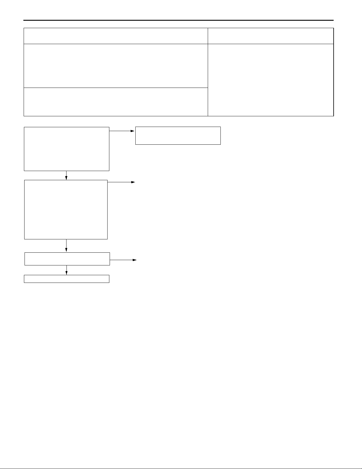
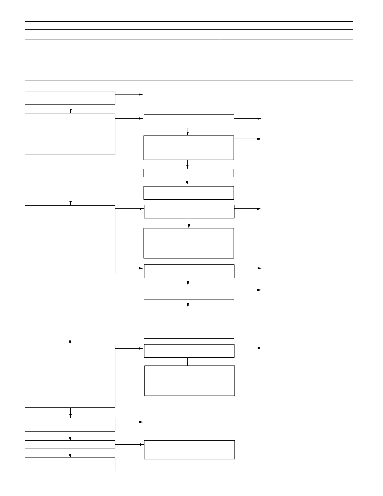
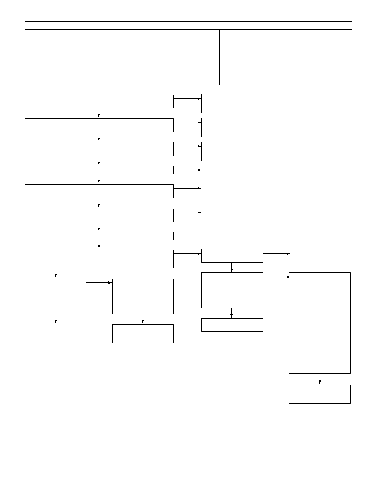
Code No. P0170 Abnormal fuel system Probable cause
Range of Check
Engine: Being learning the air/fuel ratio
D
Set Conditions
Ten seconds or more have been passed while the fuel injection amount
D
compensation value is too low.
or
Ten seconds or more have been passed while the fuel injection amount
D
compensation value is too high.
Incorrect fuel pressure
D
Malfunction of fuel supply system
D
Malfunction of oxygen sensor (front)
D
Malfunction of intake air temperature sensor
D
Malfunction of barometric pressure sensor
D
Malfunction of air flow sensor
D
Malfunction of engine-ECU <M/T>
D
Malfunction of engine-A/T-ECU <A/T>
D
13A-27
MUT-IIData list
13 Intake air temperature sensor (Refer to P.13A-75.)
OK
MUT-IIData list
21 Engine coolant temperature sensor (Refer to P.13A-75.)
OK
MUT-IIData list
25 Barometric pressure sensor (Refer to P.13A-75.)
OK
Check the injector (Refer to P.13A-93*.)
OK
Check the following connectors:
C-34 <M/T>, C-177 <A/T>, B-02, B-03, B-05, B-36
OK
Check the harness wire between the engine-ECU <M/T> or
engine-A/T-ECU <A/T> and the injector connector.
OK
Check the fuel pressure (Refer to P.13A-85*.)
OK
MUT-IIData list
81 Long-term fuel compensation (Refer to P.13A-75.)
Is fuel trim more or less than zero?
D
Less than zero
MUT-IIData list
12 Volume air flow sensor
(Refer to P.13A-75.)
Does the tester indi-
D
cate more than the
standard value?
Yes
Replace the volume air
flow sensor.
No
Check for fuel leaks
D
from injector.
Check for entry of
D
foreign matter (water,
kerosene,etc.) into the
fuel.
OK
Replace the engine-ECU
<M/T> or engine-A/T-ECU
<A/T>.
NG
NG
NG
NG
NG
NG
More than
zero
Check the intake air temperaturesensor system.(Refer to P.13A-14,
INSPECTION PROCEDURE FOR DIAGNOSTIC TROUBLE
CODE P0110.)
Check the engine coolant temperature sensor system. (Refer to
P.13A-16, INSPECTION PROCEDURE FOR DIAGNOSTIC
TROUBLE CODE P0115.)
Check the barometric pressure sensor system. (Refer to P.13A-12,
INSPECTION PROCEDURE FOR DIAGNOSTIC TROUBLE
CODE P0105.)
Replace
Repair
Repair
Check if air was drawn into
the intake system.
OK
MUT-IIData list
12 Volume air flow sensor
(Refer to P.13A-75.)
Does the tester indi-
D
cate less than the
standard value?
Yes
Replace the volume air
flow sensor.
NG
No
Repair
Check for clogging of
D
the injector.
Check for clogging of
D
the fuel filter and fuel
line.
Check the fuel pump
D
(insufficient discharge
rate.)
Check for exhaust
D
leaks (oxygen sensor
installation section,
cracks in exhaust
manifold, cracks in
front pipe, etc.).
Check for entry of
D
foreign matter (water,
kerosene,etc.) into the
fuel.
OK
Replace the engine-ECU
<M/T> or engine-A/T-ECU
<A/T>.
NOTE:
*: Refer to the ’97 GALANT Workshop Manual (Pub. No. PWDE9611)
Page 28
13A-28
MPI <4G6> -
Troubleshooting
Code No. P0201 No. 1 injector system
Code No. P0202 No. 2 injector system
Code No. P0203 No. 3 injector system
Code No. P0204 No. 4 injector system
Range of Check
Engine speed is approx. 50 - 1,000 r/min
D
The throttle position sensor output voltage is 1.15 V or less.
D
Actuator test by MUT-IIis not carried out.
D
Set Conditions
Surge voltage of injector coil is not detected for 4 seconds.
D
MUT-IIActuator Test
01 No. 1 injector
02 No. 2 injector
03 No. 3 injector
04 No. 4 injector
OK:
The idling condition should change
NG
Check the following connectors:
B-02, B-03, B-05, B-36
OK
Check the injector. (Refer to P.13A-93*.)
OK
Measure at the injector connector B-02, B-03, B-05, B-36.
Disconnect the connector, and measure at the harness side.
D
Voltage between 1 and earth (Ignition switch: ON)
D
OK:
System voltage
OK
Check the following connector:
Measure at the engine-ECU connector C-34 <M/T> or engine-A/TECU connector C-177<A/T>.
Disconnect the connector, and measure at the harness side.
D
Voltage between 1, 2, 14, 15 and earth (Ignition switch: ON)
D
<M/T>
Voltagebetween 1,2, 9,24 and earth (Ignition switch: ON)<A/T>
D
OK:
System voltage
Check trouble symptoms.
Use an analyzer to measure the signal waveform at injector
connector B-02, B-03, B-05, B-36.
Use a test harness (MB991348) to connect the connector, and
D
measure at the pick-up harness side.
Engine: Idling
D
The voltage between terminal 2 and earth
D
OK:
A normal waveform should be displayed as described
on P.13A-88 (INSPECTION PROCEDURE USING
AN ANALYZER).
Replace the engine-ECU <M/T> or engine-A/T-ECU <A/T>.
C-34 <M/T>, C-177 <A/T>
OK
OK
NG
NG
OK
NG
NG
NG
NG
NG
OK
Probable cause
Malfunction of the injector
D
Improper connector contact, open circuit or short-cir-
D
cuited harness wire of the injector circuit
Malfunction of engine-ECU <M/T>
D
Malfunction of engine-A/T-ECU <A/T>
D
Intermittent malfunction
(Refer to GROUP 00 - Points to Note for Intermittent Malfunctions.)
Repair
Replace
Check the harness wire between the engine control relay and the
injector connector, and repair if necessary.
Repair
Check the harness wire between the engine-ECU <M/T> or
engine-A/T-ECU <A/T> and the injector connector, and repair if
necessary.
Intermittent malfunction (Refer to GROUP 00 - Points to Note for
Intermittent Malfunctions.)
NOTE:
*: Refer to the ’97 GALANT Workshop Manual (Pub. No. PWDE9611)
Page 29

MPI <4G6> -
Troubleshooting
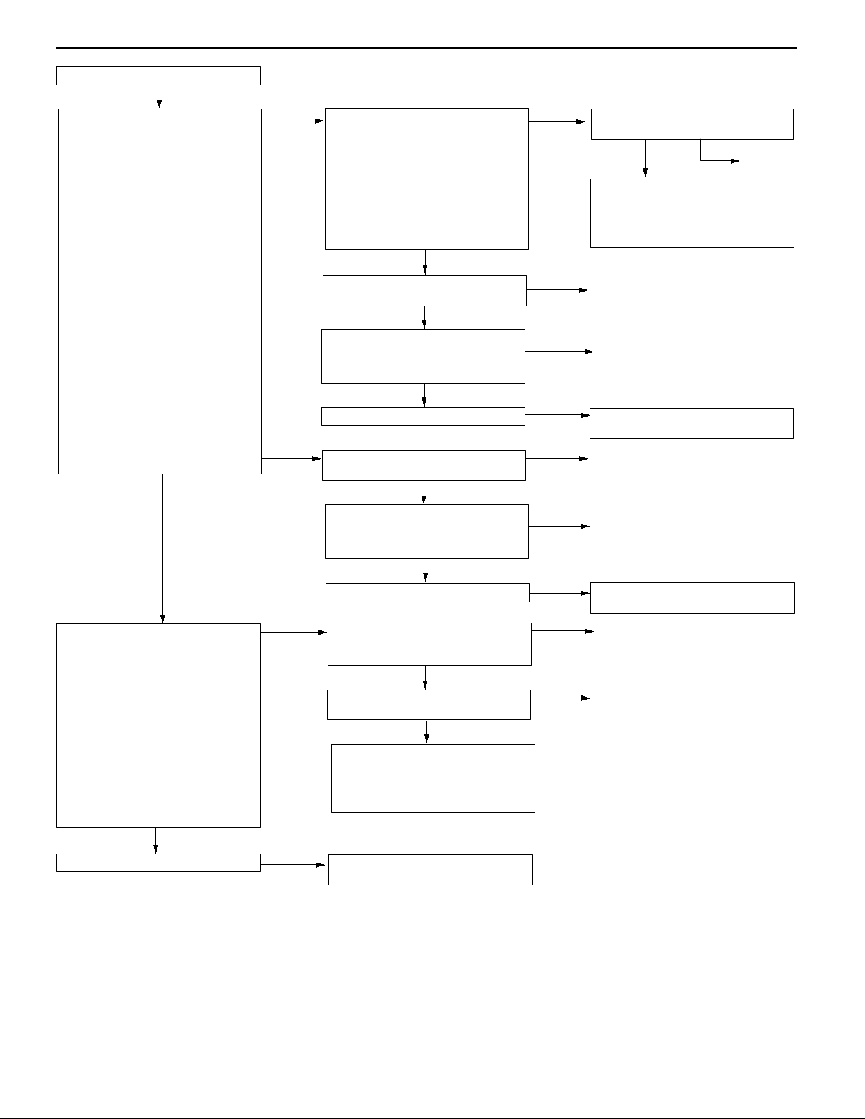
Code No. P0300 Ignition coil (power transistor) system Probable cause
Range of Check
Engine speed is approx. 50 - 4,000 r/min.
D
Engine is not cranking.
D
Set Conditions
The ignition failure sensor does not send a signal about a certain cylinder for
D
four seconds.
Malfunction of the ignition coil
D
Malfunction of the ignition failure sensor
D
Malfunction of spark plug
D
Open or short circuit in the primary ignition circuit
D
or loose connector contact
Malfunction of engine-ECU <M/T>
D
Malfunction of engine-A/T-ECU <A/T>
D
13A-29
Page 30
13A-30
MPI <4G6> -
Troubleshooting
MUT-IIActuator Test
01 No. 1 injector
02 No. 2 injector
03 No. 3 injector
04 No. 4 injector
OK:
The idling condition should
Reference
When the cylinder (defective
cylinder) where idling condition does
not change is detected after
suspending the injector, go to (1)
and inspect the spark plug, the
ignition coil, the connector, and the
harness of the defective cylinder.
(When more than one cylinder are
detected, inspect all of them.)
When all the cylinders are OK, go to
(2).
change.
(2)
(1)
Check the following connectors:
The ignition coil connectors for a
defective cylinder (B-01, B-11).
OK
Check the spark plug and the
ignition coil for a defective cylinder.
(Refer to GROUP 16 - Ignition
System.)
OK
Check the following connector:
C-34 <M/T>, C-177 <A/T>
OK
Check the harness wire between the
engine-ECU <M/T> or
engine-A/T-ECU <A/T> and the
ignition coil connector for defective
cylinder.
OK
Use an analyzer to measure the signal waveform at engine-ECU connector C-34 <M/T>
or engine-A/T-ECU connector C-177 <A/T>.
Engine: Idling
D
The voltage between the ignition coil primary signal terminal for a defective cylinder
D
and earth
OK:
A normal waveform should be displayed as described on P.13A-88* (Inspection
Procedure Using an Analyzer).
OK
Repair the ignition coil assembly for
a defective cylinder and the spark
plug.
NG
NG
NG
NG
Repair
Replace
Repair
Repair
NG
Replace the engine-ECU <M/T> or
engine-A/T-ECU <A/T>.
Use an analyzer to measure the
signal waveform at the ignition failure
sensor connector B-105.
Use test harness (MB991536) to
D
connect the connector, and
measure at the pick-up harness.
Engine: Idling
D
The voltage between terminal 2
D
and earth
OK:
A normal waveform should
be displayed as described
on P.13A-88* (INSPECTION
PROCEDURE USING AN
Reference
When a normal waveform is
displayed, compare it with that of the
ignition coil primary signal at the
engine-ECU terminal <M/T> or
engine-A/T-ECU <A/T> to determine
the cylinder (defective cylinder) with
an abnormal waveform.
®
abnormal, go to (1)
®
abnormal, go to (3)
®
displayed, go to (4).
ANALYZER).
When one or more cylinders are
When all of the cylinders are
When a normal waveform is
(1)
(3)
(4)
Check the following connectors:
C-38 <M/T>, C-176 <A/T>, B-105
OK
Check the harness wires between
the ignition failure sensor and the
engine-ECU <M/T> or
engine-A/T-ECU <A/T>, and between
the ignition failure sensor and earth.
OK
Repair the ignition failure sensor.
Check the trouble symptoms.
Check the trouble symptoms.
NG
Check the spark plug and the
ignition coil for a defective cylinder.
(Refer to GROUP 16 - Ignition
System.)
NG
NG
NG
OK
Repair
Repair
Replace the engine-ECU <M/T> or
engine-A/T-ECU <A/T>.
Intermittent malfunction
(Refer to GROUP 00 - Points to
Note for Intermittent Malfunctions.)
Page 31

MPI <4G6> -
Troubleshooting
13A-31
Code No. P0301 No. 1 cylinder misfire detected
Code No. P0302 No. 2 cylinder misfire detected
Code No. P0303 No. 3 cylinder misfire detected
Code No. P0304 No. 4 cylinder misfire detected
Range of Check
The engine speed is 500 - 4,500 r/min.
D
While the engine is running except deceleration and sudden acceleration.
D
Set Conditions
The number of misfires exceeds a predetermined number per 200 engine
D
revolutions (Misfire has occurred in only one cylinder).
or
The number of misfires exceeds a predetermined number per 100 engine
D
revolutions (Misfire has occurred in only one cylinder).
Check the following connectors:
B-01, B-11
OK
Measure at ignition coil connectors
B-01, B-11.
Disconnect the connector and
D
measure at the harness side.
(1) The voltage between terminal 1
and earth
(Ignition switch: ON)
OK:
(2) The voltage between terminal 3
(3) The resistance between terminal
Check the ignition coil (Refer to
GROUP 16 - Ignition System.)
System voltage
and earth
(Engine: Cranking)
OK:
0.5 - 4.0 V
2 and earth
OK:
2Wor less
OK
NG
(1) NG
(2) NG
(3) NG
Repair
Check the following connectors:
B-105, C-92, C-105, C-131
Check the ignition failure sensor
(Refer to GROUP 16 - Ignition
System.)
Check the harness wire between the
ignition coil and the ignition failure
sensor, and between the ignition
switch and the ignition failure sensor.
Check the following connector:
C-34 <M/T>, C-177 <A/T>
Check the harness wire between the
ignition coil and the engine-ECU
<M/T> or engine-A/T-ECU <A/T>.
Check the trouble symptoms.
Check the harness wire between the
ignition coil and the earth, and repair
if necessary.
OK
OK
OK
OK
Probable cause
Malfunction of the ignition system
D
Abnormal compression
D
Malfunction of injector
D
Malfunction of engine-ECU <M/T>
D
Malfunction of engine-A/T-ECU <A/T>
D
NG
NG
NG
NG
NG
Repair
Replace
Repair
Repair
Replace the engine-ECU <M/T> or
engine-A/T-ECU <A/T>.
Check the spark plugs.
OK
Check the compression pressure.
(Refer to GROUP 11A - On-vehicle
Service.)
OK
Check the trouble symptoms.
NG
Replace the engine-ECU <M/T> or
engine-A/T-ECU <A/T>.
NG
NG
Replace
Repair
Page 32

13A-32
MPI <4G6> -
Troubleshooting
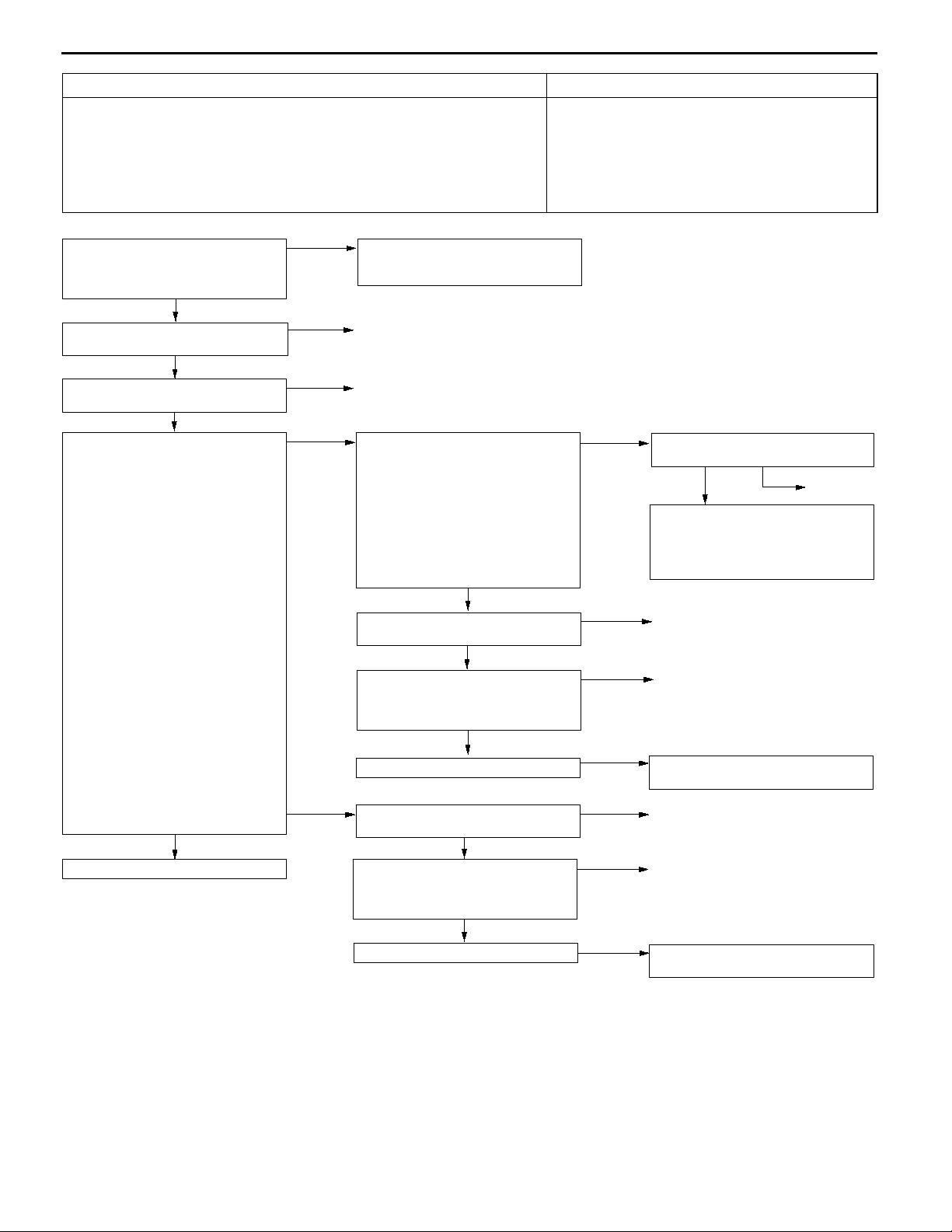
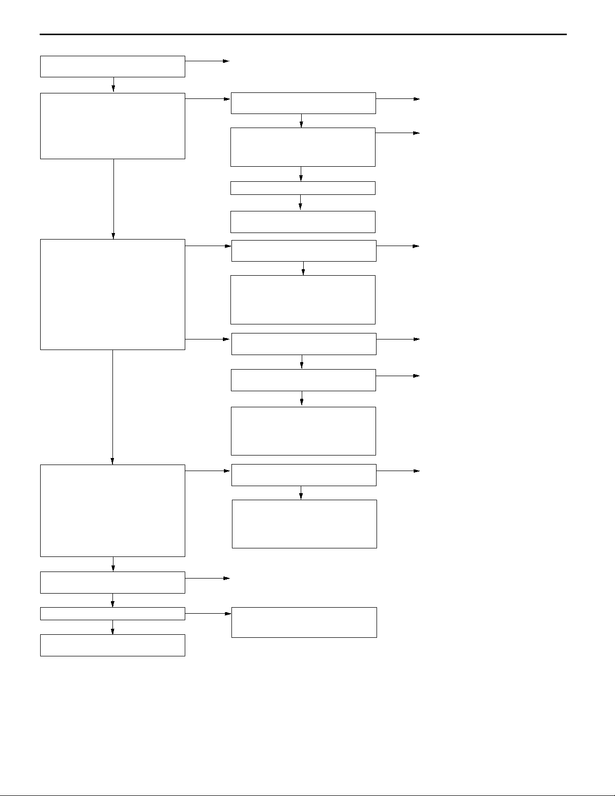
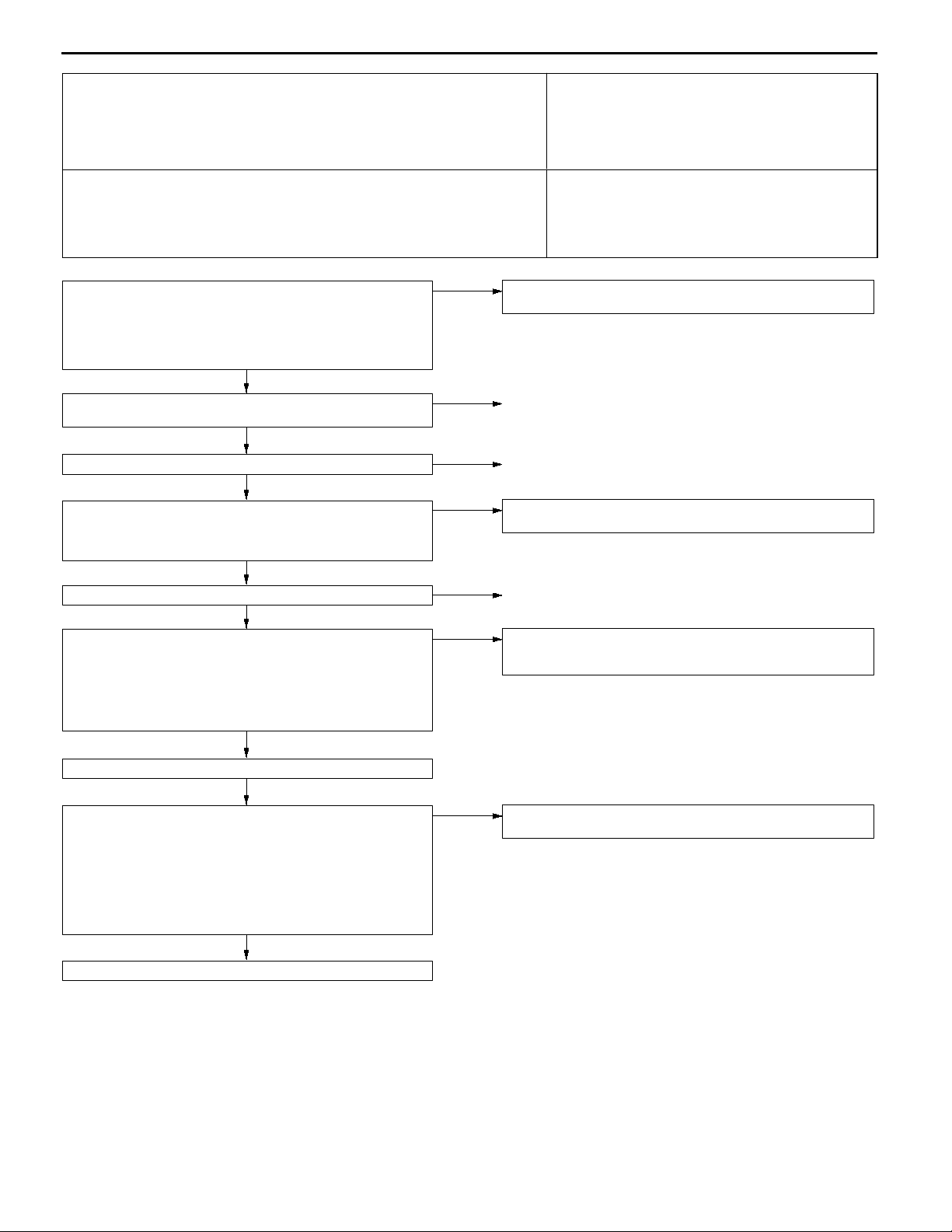
Code No. P0325 Detonation sensor system Probable cause
Range of Check
Engine: Two seconds after the engine has been started
D
Set Conditions
Changes in sensor output voltage (detonation sensor peak voltage per 1/2
D
crankshaft rotation) in 200 consecutive cycles are 0.06 V or less.
Malfunction of the detonation sensor
D
Open or short circuit in the detonation sensor
D
circuit or loose connector contact
Malfunction of engine-ECU <M/T>
D
Malfunction of engine-A/T-ECU <A/T>
D
Check the following connector:
Measure at the detonation sensor connector B-34.
Disconnect the connector and measure at the harness
D
side.
The resistance between terminal 2 and earth
D
OK:
2Wor less
Check the following connector:
Check the harness wire between the detonation sensor and
the engine-ECU <M/T> or engine-A/T-ECU <A/T>.
Check the trouble symptoms.
Replace the detonation sensor.
Check the trouble symptoms.
Replace the engine-ECU <M/T> or engine-A/T-ECU <A/T>.
B-34
OK
OK
C-40 <M/T>, C-175 <A/T>
OK
OK
NG
NG
NG
NG
NG
NG
OK
Repair
Check the harness wire between the detonation sensor and
earth, and repair if necessary.
Repair
Repair
Intermittent malfunction
(Refer to GROUP 00 - Points to Note for Intermittent
Malfunctions.)
Code No. P0335 Crank angle sensor system Probable cause
Range of Check
Engine is cranking
D
Set Conditions
Sensor output voltage does not change for 4 seconds (no pulse signal input).
D
Malfunction of the crank angle sensor.
D
Open or short circuit in the crank angle sensor
D
circuit or loose connector contact.
Malfunction of engine-ECU <M/T>
D
Malfunction of engine-A/T-ECU <A/T>
D
Page 33

MPI <4G6> -
Troubleshooting
13A-33
MUT-IIData list
22 Crank angle sensor
OK:
Refer to P.13A-75, DATA
LIST REFERENCE TABLE.
NG
Check the following connector:
B-77
OK
Measure at the crank angle sensor
connector B-77.
Disconnect the connector and
D
measure at the harness side.
(1) The resistance between terminal
1 and earth
OK:
(2) The voltage between terminal 2
(3) The voltage between terminal 3
2Wor less
and earth
(Ignition switch: ON)
OK:
4.8 - 5.2 V
and earth
(Ignition switch: ON)
OK:
System voltage
OK
OK
NG
(1) NG
(2) NG
(3) NG
Intermittent malfunction
(Refer to GROUP 00 - Points to
Note for Intermittent Malfunctions.)
Repair
Check the harness between the
crank angle sensor and earth, and
repair if necessary.
Measure at engine-ECU connector
C-40 <M/T> or engine-A/T-ECU
connector C-176 <A/T>.
Measure the voltage at the
D
engine-ECU terminal <M/T> or
engine-A/T-ECU terminal <A/T>.
Disconnect the connector B-77
D
Ignition switch: ON
D
The voltage between terminal 89
D
<M/T>, 45 <A/T> and earth
OK:
4.8 - 5.2 V
NG
Check the following connector:
C-40 <M/T>, C-176 <A/T>
OK
Check the harness wire between the
crank angle sensor and the
engine-ECU <M/T> or
engine-A/T-ECU <A/T>.
OK
Check the trouble symptoms.
Check the following connector:
C-31
OK
OK
NG
NG
NG
NG
Check the following connector:
C-40 <M/T>, C-176 <A/T>
OK
Check the harness wire between the
crank angle sensor and the
engine-ECU <M/T> or
engine-A/T-ECU <A/T>, and repair if
necessary.
Repair
Repair
Replace the engine-ECU <M/T> or
engine-A/T-ECU <A/T>.
Repair
NG
Repair
Use an analyzer to measure the
output waveform at the crank angle
sensor connector B-77.
Use the test harness (MB991658)
D
to connect the connector, and
measure at the pick-up harness
side.
Engine: Idling
D
The voltage between terminal 3
D
and earth
OK:
A normal waveform should
be displayed as described
on P.13A-88 (Inspection
Procedure Using an Analyzer). Its maximum value
should be 4.8 V or more,
and its minimum value
should be 0.6 V or less
with no noise in waveform.
OK
Check the trouble symptoms.
NG
Replace the engine-ECU <M/T> or
engine-A/T-ECU <A/T>.
NG
Check the harness wire between the
crank angle sensor and the engine
control relay, and repair if necessary.
Check the crank angle sensor vane.
OK
Replace the crank angle sensor.
Check the trouble symptoms.
NG
Check the following connector:
C-40 <M/T>, C-176 <A/T>
OK
Check the harness wires between
the crank angle sensor and the
engine-ECU <M/T> or
engine-A/T-ECU <A/T>, crank angle
sensor and the engine control relay,
and the crank angle sensor and
earth. Then, repair if necessary.
NG
NG
Replace
Repair
Page 34

13A-34
MPI <4G6> -
Troubleshooting
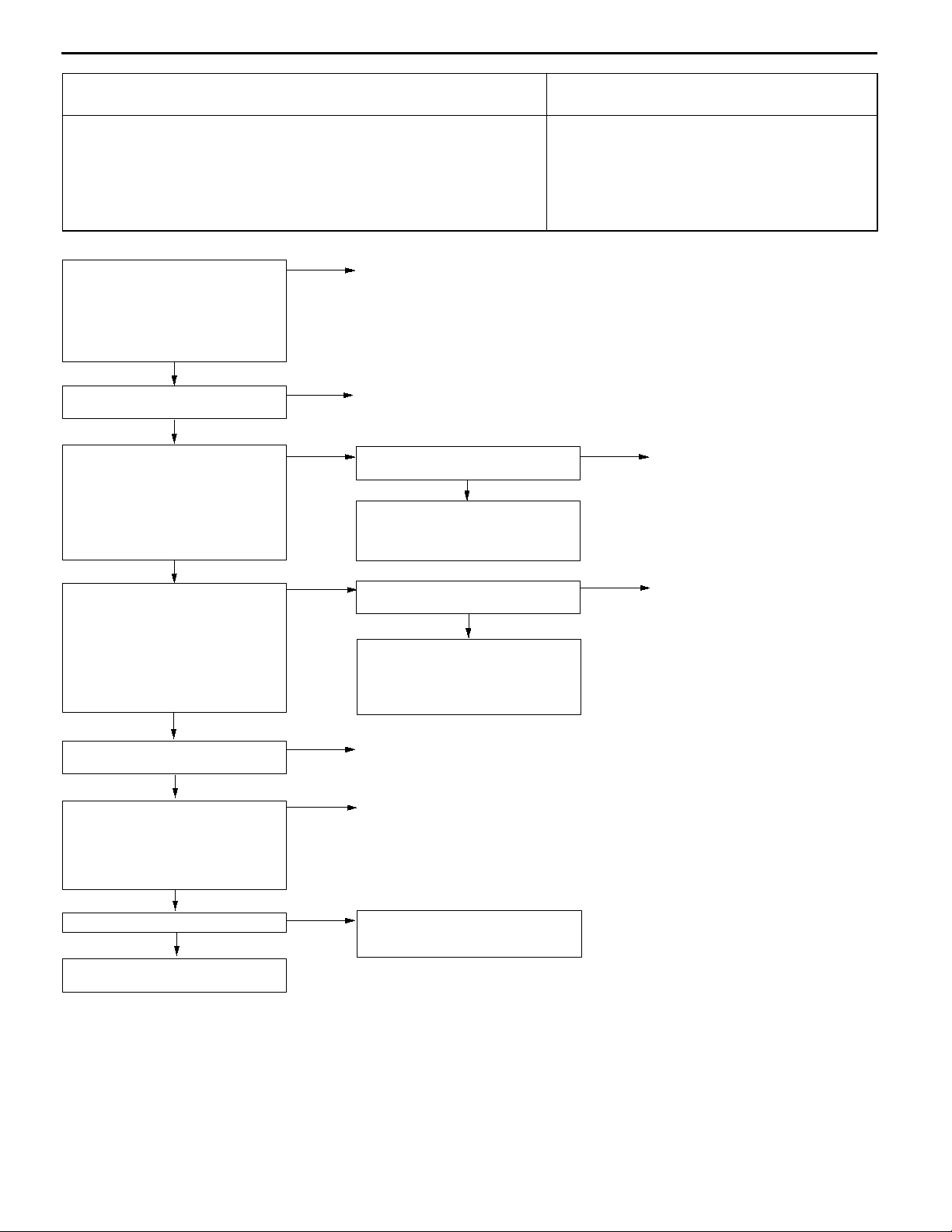
Code No. P0340 Camshaft position sensor system Probable cause
Range of Check
Ignition switch: ON
D
Engine speed: 50 r/min or more
D
Set Conditions
The sensor output voltage does not change for 4 seconds (no pulse signal
D
input).
Malfunction of the camshaft position sensor
D
Open or short circuit in the camshaft position
D
sensor circuit or loose connector contact.
Malfunction of engine-ECU <M/T>
D
Malfunction of engine-A/T-ECU <A/T>
D
Page 35

MPI <4G6> -
Troubleshooting
13A-35
Check the following connector:
B-64
OK
Measure at camshaft position sensor
connector B-64.
Disconnect the connector and
D
measure at the harness side.
(1) The voltage between terminal 3
and earth
(Ignition switch: ON)
OK:
(2) The voltage between terminal 2
(3) The resistance between terminal
Use an analyzer to measure the
output waveform at camshaft position
sensor connector B-64.
D
D
D
Check the trouble symptoms.
Replace the engine-ECU <M/T> or
engine-A/T-ECU <A/T>.
System voltage
and earth
(Ignition switch: ON)
OK:
4.8 - 5.2 V
1 and earth
OK:
2Wor less
OK
Use test harness (MB991709) to
connect the connector, and
measure at the pick-up harness.
Engine: Idling
The voltage between terminal 2
and earth
OK:
A normal waveform should
be displayed as described
on P.13A-88 (Inspection
Procedure Using an Analyzer), its maximum value
should be 4.8 V or more,
and its minimum value
should be 0.6 V or less
with no noise in waveform
OK
NG
.
NG
(1) NG
(2) NG
(3) NG
NG
OK
Repair
Check the following connector:
C-31
OK
Check the harness wire between the
camshaft position sensor connector
and the engine control relay, and
repair if necessary.
Measure at engine-ECU connector
C-40 <M/T> or engine-A/T-ECU
connector C-176 <A/T>.
Measure the voltage at the
D
engine-ECU terminal <M/T> or
engine-A/T-ECU terminal <A/T>.
Disconnect connector B-64.
D
Ignition switch: ON
D
The voltage between terminal 88
D
<M/T>, 56 <A/T> and earth
OK:
4.8 - 5.2 V
NG
Check the following connector:
C-40 <M/T>, C-176 <A/T>
OK
Check the harness wire between the
intermediate connector and the
engine-ECU <M/T> or
engine-A/T-ECU <A/T>.
OK
Check the trouble symptoms.
Check the harness wire between the
camshaft position sensor connector
and earth, and repair if necessary.
Check the camshaft position sensing
cylinder.
Replace the camshaft position
sensor.
OK
Check the trouble symptoms.
NG
Check the following connectors:
B-64, C-31, C-40, C-176
OK
Check the harness wires between the camshaft position sensor connector and the
engine-ECU <M/T> or engine-A/T-ECU <A/T>, the camshaft position sensor connector
and the engine control relay, and the camshaft position sensor connector and earth.
Then, repair if necessary.
Intermittent malfunction
(Refer to GROUP 00 - Points to Note for Intermittent Malfunctions.)
NG
OK
NG
NG
NG
NG
NG
Repair
Check the following connector:
C-40 <M/T>, C-176 <A/T>
OK
Check the harness wire between the
camshaft position sensor connector
and the engine-ECU <M/T> or
engine-A/T-ECU <A/T>, and repair if
necessary.
Repair
Repair
Replace the engine-ECU <M/T> or
engine-A/T-ECU <A/T>.
Replace
Repair
NG
Repair
Page 36

13A-36
MPI <4G6> -
Troubleshooting
Code No. P0403 EGR control solenoid valve system Probable cause
Range of Check
Ignition switch: ON
D
Battery voltage is 10 V or more.
D
Set Conditions
The solenoid coil surge voltage (battery voltage + 2 V) is not detected when
D
the purge control solenoid valve is turned from on to off.
Malfunction of the EGR control solenoid valve
D
Open or short circuit in the EGR control solenoid
D
valve circuit or loose connector contact
Malfunction of engine-ECU <M/T>
D
Malfunction of engine-A/T-ECU <A/T>
D
MUT-IIActuator Test
10 EGR control solenoid valve
OK:
Operating sound can be
heard and the valve vibrates.
NG
Measure at the EGR control solenoid
valve connector B-06.
Disconnect the connector, and
D
measure at the solenoid valve
side.
The resistance between terminals
D
1 and 2
OK:
28 - 36W(at 20_C)
OK
Check the following connector:
B-06
OK
Measure at the EGR control solenoid
valve connector B-06.
Disconnect the connector and
D
measure at the harness side.
Ignition switch: ON
D
The voltage between terminal 1
D
and earth
OK:
System voltage
OK
Measure at engine-ECU connector
C-34 <M/T> or engine-A/T-ECU
connector C-177 <A/T>.
Measure the voltage at the
D
engine-ECU terminal <M/T> or
engine-A/T-ECU terminal <A/T>.
Ignition switch: ON
D
The voltage between terminal 6
D
and earth
OK:
System voltage
OK
Check the following connector:
C-34 <M/T>, C-177 <A/T>
OK
Check the harness wires between
the EGR control solenoid valve and
the engine control relay, and
between the EGR control solenoid
valve and the engine-ECU <M/T> or
engine-A/T-ECU <A/T>.
OK
Check the trouble symptoms.
NG
OK
NG
NG
NG
NG
NG
NG
Intermittent malfunction
(Refer to GROUP 00 - Points to
Note for Intermittent Malfunctions.)
Replace
Repair
Check the following connector:
C-31
NG
Check the harness wire between the
EGR control solenoid valve and the
engine control relay, and repair if
necessary.
Check the following connector:
C-34 <M/T>, C-177 <A/T>
OK
Check the harness wire between the
EGR control solenoid valve and the
engine-ECU <M/T> or
engine-A/T-ECU <A/T>.
OK
Replace the engine-ECU <M/T> or
engine-A/T-ECU <A/T>.
Repair
Repair
NG
NG
NG
Repair
Repair
Repair
Replace the engine-ECU <M/T> or
engine-A/T-ECU <A/T>.
Page 37

MPI <4G6> -
Troubleshooting
Code No. P0420 Catalyst malfunction Probable cause
Range of Check
The engine speed is 3,000 r/min or less.
D
During driving
D
During air/fuel ratio feedback control
D
Set Conditions
The ratio between the oxygen sensor (rear) and the oxygen sensor (front)
D
output frequencies reaches 0.8 per 12 seconds on average.
Malfunction of catalyst
D
Malfunction of the oxygen sensor (front)
D
Malfunction of the oxygen sensor (rear)
D
Malfunction of engine-ECU <M/T>
D
Malfunction of engine-A/T-ECU <A/T>
D
13A-37
Check the exhaust manifold. (Are there any cracks?)
OK
MUT-IIData list
59 Oxygen sensor (rear)
Transmission: 2nd gear <M/T>, L range <A/T>
D
Drive with wide open throttle
D
OK:
600 - 1,000 mV
OK
MUT-IIData list
11 Oxygen sensor (front)
OK:
600 - 1,000 mV when racing suddenly
OK
MUT-IIData list
11 Oxygen sensor (front)
Transmission: 2nd gear <M/T>, L range <A/T>
D
OK:
Changeover between 0 - 400 mV and 600 - 1,000
mV occur 15 times in 10 seconds.
OK
Replace the oxygen sensor (rear).
Check the trouble symptoms.
NG
Replace the catalytic converter.
NG
NG
NG
NG
Repair
Check the oxygen sensor (rear) system <sensor 2>
(Refer to P.13A-24, INSPECTION PROCEDURE FOR
DIAGNOSTIC TROUBLE CODE P0136.)
Check the oxygen sensor (front) system <sensor 1>
(Refer to P.13A-21, INSPECTION PROCEDURE FOR
DIAGNOSTIC TROUBLE CODE P0130.)
Replace the oxygen sensor (front).
Check the trouble symptoms.
NG
Replace the engine-ECU <M/T> or engine-A/T-ECU <A/T>.
Page 38

13A-38
MPI <4G6> -
Troubleshooting
Code No. P0443 Purge control solenoid valve system Probable cause
Range of Check
Ignition switch: ON
D
Battery voltage is 10 V or more.
D
Set Conditions
The solenoid coil surge voltage (battery voltage + 2 V) is not detected when
D
the purge control solenoid valve is turned from on to off.
Malfunction of the purge control solenoid valve
D
Open or short circuit in the purge control solenoid
D
valve circuit or loose connector contact
Malfunction of engine-ECU <M/T>
D
Malfunction of engine-A/T-ECU <A/T>
D
MUT-IIActuator Test
08 Purge control solenoid valve
OK:
Operating sound can be
heard and the valve vibrates.
NG
Measure at the purge control
solenoid valve connector B-04.
Disconnect the connector, and
D
measure at the solenoid valve
side.
The resistance between terminals
D
1 and 2
OK:
28 - 36W(at 20_C)
OK
Check the following connector:
B-04
OK
Measure at the purge control
solenoid valve connector B-04.
Disconnect the connector and
D
measure at the harness side.
Ignition switch: ON
D
The voltage between terminal 2
D
and earth
OK:
System voltage
OK
Measure at engine-ECU connector
C-34 <M/T> or engine-A/T-ECU
connector C-177 <A/T>.
Measure the voltage at the
D
engine-ECU terminal <M/T> or
engine-A/T-ECU terminal <A/T>.
Ignition switch: ON
D
The voltage between terminal 9
D
<M/T>, 34 <A/T> and earth
OK:
System voltage
OK
Check the following connector:
C-34 <M/T>, C-177 <A/T>
OK
Check the harness wires between
the purge control solenoid valve and
the engine control relay, and
between the purge control solenoid
valve and the engine-ECU <M/T> or
engine-A/T-ECU <A/T>.
OK
OK
NG
NG
NG
NG
NG
NG
Intermittent malfunction
(Refer to GROUP 00 - Points to
Note for Intermittent Malfunctions.)
Replace
Repair
Check the following connector:
C-31
NG
Check the harness wire between the
purge control solenoid valve and the
engine control relay, and repair if
necessary.
Check the following connector:
C-34 <M/T>, C-177 <A/T>
OK
Check the harness wire between the
purge control solenoid valve and the
engine-ECU <M/T> or
engine-A/T-ECU <A/T>.
OK
Replace the engine-ECU <M/T> or
engine-A/T-ECU <A/T>.
Repair
Repair
NG
NG
NG
Repair
Repair
Repair
Check the trouble symptoms.
NG
Replace the engine-ECU <M/T> or
engine-A/T-ECU <A/T>.
Page 39

MPI <4G6> -
Troubleshooting
Code No. P0500 Vehicle speed sensor system Probable cause
Range of Check
Engine: Two seconds after the engine was started
D
Idle switch: OFF
D
Engine speed: 2,500 r/min or more
D
During high engine load
D
Set Conditions
The sensor output voltage does not change for 2 seconds (no pulse signal
D
input).
Malfunction of the vehicle speed sensor
D
Open or short circuit in the vehicle speed sensor
D
circuit or loose connector contact
Malfunction of engine-ECU <M/T>
D
Malfunction of engine-A/C-ECU <A/T>
D
13A-39
Does the speedometer operate normally?
Yes
Use an analyzer to measure the output waveform of the
vehicle speed sensor at engine-ECU connector C-40 <M/T> or
engine-A/T-ECU connector C-175 <A/T>.
Driving the vehicle
D
The voltage between terminal 86 <M/T>, 80 <A/T> and
D
earth
OK:
A normal waveform should be displayed as described
in OSCILLOSCOPE INSPECTION PROCEDURE,
and noise should not be displayed in the waveform.
(Refer to GROUP 23 - Troubleshooting.)
OK
Check the following connector:
Check the trouble symptoms.
Replace the engine-ECU <M/T> or engine-A/T-ECU <A/T>.
C-40 <M/T>, C-175 <A/T>
OK
NG
No
NG
NG
Check the vehicle speed sensor
(Refer to GROUP 54 - Combination Meter.)
Check the following connectors:
B-65, B-66, C-40 <M/T>, B-67, C-175 <A/T>, C-47 <LHD>,
C-49 <RHD>
OK
Check the harness wire between vehicle speed sensor
connector and the engine-ECU <M/T> or engine-A/T-ECU
<A/T>, and repair if necessary.
Repair
Code No. P0505 Idle speed control (ISC) system Probable cause
Check Area
Vehicle speed has reached 1.5 km/h at least once.
D
Under the closed loop idle speed control.
D
Judgment Criteria
Actual idle speed has continued to be higher than the target idle speed by
D
300 r/min or more for 10 sec.
Check Area
Vehicle speed has reached 1.5 km/h at least once.
D
During idle speed closed loop control.
D
The highest temperature at the last drive is 45_C or less.
D
Engine coolant temperature is approx. 80_C or more.
D
Battery voltage is 10 V or more.
D
Barometric pressure is 76 kPa or higher.
D
Intake air temperature is - 10_C or more.
D
Judgment Criteria
Actual idle speed has been minimum 200 r/min higher than the target idle
D
speed for ten seconds.
Check Area
During idle speed closed loop control.
D
Engine coolant temperature is about 80_C or higher.
D
Battery voltage is 10 V or higher.
D
Power steering switch is off.
D
Volumetric efficiency is 40 % or lower.
D
Barometric pressure is 76 kPa or higher.
D
Intake air temperature is - 10_C or more.
D
Judgment Criteria
Actual idle speed has been minimum 100 r/min higher than the target idle
D
speed for ten seconds.
Malfunction of idle speed control (ISC) servo
D
Improper connector contact, open circuit or
D
short-circuit harness wire
Malfunction of engine-ECU <M/T>
D
Malfunction of engine-A/C-ECU <A/T>
D
NG
Repair
Page 40

13A-40
MPI <4G6> -
Troubleshooting
MUT-IISelf-Diag code
Is any diagnosis code other than No.
P0505 output?
No
Check intake air hose and intake
manifold for air intake.
OK
Check the throttle body (around the
throttle valve) for contamination.
OK
Check the idle speed control (ISC)
servo. (Refer to P.13C-95*.)
OK
Check the following connector:
B-10
OK
Measure at the idle control servo
connector B-10.
Disconnect the connector, and
D
measure at the harness side.
Ignition switch: ON
D
The voltage between terminal 2
D
and earth
The voltage between terminal 5
D
and earth
OK:
System voltage
OK
Measureat engine-ECU connectorC-34
<M/T> or engine-A/T-ECU connector
C-177 <A/T>.
Use test harness (MB991709) to
D
connecttheconnector,andmeasure
at the pick-up harness side.
The voltage between terminal 4
D
<M/T> or 14 <A/T> and earth
The voltage between terminal 5
D
<M/T> or 15 <A/T> and earth
The voltage between terminal 17
D
<M/T> or 28 <A/T> and earth
The voltage between terminal 18
D
<M/T> or 29 <A/T> and earth
OK:
The voltage changes as follows for three seconds when
the ignition switch is turned
ON.
(When using a circuit tester)
5 V and 8 V alternates
(When using an analyzer)
1 V or lessand system voltage
alternates
OK
To the next page
Yes
NG
NG
NG
NG
NG
NG
RefertoP.13A-8, INSPECTIONCHART
FOR DIAGNOSIS CODES.
Repair
Clean around the throttle valve.
(Refer to P.13C-81*.)
Replace
Repair
Check the following connectors:
C-49 <LHD>, C-31
OK
Check the harness wire between the
engine control relay and the idle speed
control servo, and repair if necessary.
Check the following connector:
C-34 <M/T>, C-177 <A/T>
OK
Check the harness wire between the
idle speed control servo and the engineECU <M/T> or engine-A/T-ECU <A/T>.
OK
Replace the engine-ECU <M/T> or engine-A/T-ECU <A/T>.
NG
NG
Repair
Repair
NOTE:
*: Refer to the ’97 GALANT Workshop Manual (Pub. No. PWDE9611)
Page 41

MPI <4G6> -
From the previous page
OK
Check the following connector:
C-34 <M/T>, C-177 <A/T>
OK
Check the harness wires between
the engine control relay and the idle
speed control servo, and between
the idle speed control servo and the
engine-ECU <M/T> or
engine-A/T-ECU <A/T>.
OK
Check trouble symptoms.
NG
Replace the engine-ECU <M/T> or
engine-A/T-ECU <A/T>.
MPI <4G6> -
NG
NG
OK
Repair
Repair
Intermittent malfunction
(Refer to GROUP 00 - Points to
Note for Intermittent Malfunctions.)
Troubleshooting
Troubleshooting
Code No. P0510 Idle Position Switch System Probable cause
Check Area
Throttle position sensor output voltage is 2.0 V or more.
D
Judgment Criteria
Idle position switch has been turned on.
D
Check Area
Repeat the *1 drive and *2 stop 15 times or more.
D
*1 drive: The vehicle remains under the following conditions for at least two
seconds; engine speed is 1,500 rpm or higher, air flow sensor output
waveform is 100 Hz or higher, and vehicle speed is more than 30 km/h for
two seconds.
*2 stop: The vehicle remains under the following conditions for at least two
seconds; engine speed is 800 rpm or lower, and vehicle speed is less than
1.5 km/h.
Judgment Criteria
Idle position switch remains off.
D
Malfunction of idle position switch
D
Open or shorted idle position switch circuit, or
D
loose connector.
Malfunction of engine-ECU <M/T>
D
Malfunction of engine-A/T-ECU <A/T>
D
13A-41
MUT-IIData list
26 Idle position switch
(Refer to P.13A-75, DATA LIST REFERENCE TABLE.)
NG
Check the idle position switch. (Refer to P.13A-91*.)
OK
Check the following connector:
Measure at the throttle position sensor connector B-07.
Disconnect the connector, and measure at the harness
D
side.
Voltage between 3 and ground (Ignition switch: ON)
D
OK:
4 V or higher
Continuity between 4 and ground
D
OK:
Continuity
OK
Check the following
connector:
Check trouble symptom.
Replace the engine-ECU <M/T> or engine-A/T-ECU <A/T>.
B-07
OK
NG
B-07
OK
Repair
NG
OK
NG
NG
NG
Transient malfunction (Refer to GROUP 00 - Points to Note
for Intermittent Malfunctions.)
Replace the throttle position sensor (TPS).
Repair
Check the following
connectors:
<M/T>, C-175 and
C-176 <A/T>, C-47
<LHD>, C-49 <RHD>
Check trouble symptom.
Check the harness wire between engine-ECU <M/T> or
engine-A/T-ECU <A/T> and throttle position sensor connector.
Replace the engine-ECU
<M/T> or engine-A/TECU <A/T>.
C-40
OK
NG
OK
NG
Repair
NG
Repair
NOTE:
*: Refer to the ’97 GALANT Workshop Manual (Pub. No. PWDE9611)
Page 42

13A-42
MPI <4G6> -
Troubleshooting
Code No. P0551 Power steering fluid pressure switch
system
Check Area
Intake air temperature is - 10_C or higher.
D
Barometric pressure is 76 kPa or higher.
D
Engine coolant temperature is 30_C or more.
D
Repeat the *1 drive and *2 stop ten times or more.
D
*1: Engine speed is 2,500 r/min or higher, volumetric efficiency is 55 % or higher
and vehicle speed is 5 km/h or higher for 4 seconds or more.
*2: Vehicle speed is 1.5 km/h or lower.
Judgment Criteria
Power steering pressure switch remains on.
D
MUT-IIData list
27 Power steering fluid pressure switch
(Refer to P.13A-75, DATA LIST REFERENCE TABLE.)
NG
Check the power steering pressure switch.
(Refer to GROUP 37A - On-vehicle Service.)
OK
Check the following connector:
Measure at the power steering pressure switch connector
B-76.
Disconnect the connector and measure at the harness
D
side.
Voltage between 1 and ground (Ignition switch: ON)
D
OK:
Battery positive voltage
OK
Check the following
connector:
Check trouble symptom.
Replace the engine-ECU <M/T> or engine-A/T-ECU <A/T>.
B-76
OK
OK
NG
B-76
OK
Repair
OK
NG
NG
NG
Transient malfunction (Refer to GROUP 00 - Points to Note
for Intermittent Malfunctions.)
Replace
Repair
Check the following
connector:
C-176 <A/T>
Check trouble symptom.
Check the harness wire
between engine-ECU
<M/T> or engine-ATECU <A/T> and power
steering pressure switch
connector.
Replace the engine-ECU
<M/T> or engine-ATECU <A/T>.
Probable cause
Power steering fluid pressure switch failed.
D
Open or shorted power steering fluid pressure
D
switch circuit or loose connector
Malfunction of the engine-ECU <M/T>
D
Malfunction of the engine-A/C-ECU <A/T>
D
NG
C-36 <M/T>,
OK
NG
NG
OK
Repair
Repair
Page 43

MPI <4G6> -
Troubleshooting
Code No. P1500 Alternator FR terminal system Probable cause
Range of Check
Engine speed: 50 r/min or more
D
Set Conditions
Input voltage from the alternator FR terminal is system voltage for 20
D
seconds.
Open circuit in alternator FR terminal circuit
D
Malfunction of engine-ECU <M/T>
D
Malfunction of engine-A/T-ECU <A/T>
D
13A-43
Check the following connector:
B-38
OK
Measure at alternator connector
B-38.
Use test harness (MB991519) to
D
connect the connector, and
measure at the pick-up harness.
Ignition switch: ON
D
The voltage between terminal 4
D
and earth
OK:
9 - 10 V
OK
Measure at alternator connector
B-38.
Use test harness (MB991519) to
D
connect the connector, and
measure at the pick-up harness.
Engine: Idling (After warming up)
D
Radiator fan: Not operating
D
The voltage between terminal 4
D
and earth
OK:
The voltage drops when
the headlamps are turned
on.
NG
NG
NG
Repair
Measure at engine-ECU connector
C-36 <M/T> or engine-A/T-ECU
connector C-176 <A/T>.
Measure the voltage at the
D
engine-ECU terminal <M/T> or
engine-A/T-ECU terminal <A/T>.
Ignition switch: ON
D
The voltage between terminal 52
D
<M/T>, 54 <A/T> and earth
OK:
9 - 10 V
NG
Check the following connector:
C-36 <M/T>, C-176 <A/T>
OK
Check the harness wire between the
intermediate connector and the
engine-ECU <M/T> or
engine-A/T-ECU <A/T>.
OK
Check the trouble symptoms.
Check the following connectors:
C-36 <M/T>, C-176 <A/T>, B-31
OK
Check the harness wire between the
alternator connector and the
engine-ECU <M/T> or
engine-A/T-ECU <A/T>.
OK
Check the trouble symptoms.
NG
Replace the alternator.
NG
NG
NG
NG
NG
NG
Check the following connectors:
C-36 <M/T>, C-176 <A/T>, B-31
OK
Check the harness wire between the
intermediate connector and the
engine-ECU <M/T> or
engine-A/T-ECU <A/T>, and repair if
necessary.
Repair
Repair
Replace the engine-ECU <M/T> or
engine-A/T-ECU <A/T>.
Replace
Repair
NG
Repair
OK
Check the trouble symptoms.
NG
Replace the engine-ECU <M/T> or
engine-A/T-ECU <A/T>.
OK
Intermittent malfunction
(Refer to GROUP 00 - Points to
Note for Intermittent Malfunctions.)
Page 44

13A-44
MPI <4G6> -
Troubleshooting
Cord No. P1610 Immobilizer system Probable cause
Range of Check
Ignition switch: ON
D
Set Conditions
Improper communication between the engine-ECU <M/T> or engine-A/T-ECU
D
<A/T> and the immobilizer-ECU
Open or short circuit, or loose connector contact
D
Malfunction of the immobilizer-ECU
D
Malfunction of the engine-ECU <M/T>
D
Malfunction of the engine-A/T-ECU <A/T>
D
NOTE
(1) If the registered ignition keys are close each other when starting the engine, radio interference may
cause this code to be displayed.
(2) This code may be displayed when registering the key ID code.
Check the following connectors:
C-38 <M/T>, C-174 <A/T>, C-81,
C-173
OK
Check the harness wire between the
immobilizer-ECU and the engine-ECU
<M/T> or engine-A/T-ECU <A/T>.
OK
Check the trouble symptoms.
NG
Replace the immobilizer-ECU.
NG
NG
Repair
Replace
Check the trouble symptoms.
NG
Replace the engine-ECU <M/T> or
engine-A/T-ECU <A/T>.
Page 45

MPI <4G6> -
Troubleshooting
INSPECTION CHART FOR TROUBLE SYMPTOMS
13A-45
Trouble symptom Inspection
procedure
No.
Communication Communication with all systems is not possible. 1 13A-46
with MUT-IIis
impossible.
Engine warning
lamp and
related parts
Starting No initial combustion (starting impossible) 5 13A-48
Idling stability Unstable idling (Rough idling, hunting) 8 13A-51
(Improper idling)
Idling stability When the engine is cold, it stalls at idling. (Die out) 11 13A-55
(Engine stalls)
Communication with engine-ECU <M/T> or engine-A/T-ECU <A/T>
only is not possible.
The engine warning lamp does not illuminate right after the ignition
switch is turned to the ON position.
The engine warning lamp remains illuminating and never goes out. 4 13A-47
Initial combustion but no complete combustion
(starting impossible)
Long time to start (improper starting) 7 13A-50
Idling speed is high. (Improper idling speed) 9 13A-53
Idling speed is low. (Improper idling speed) 10 13A-54
When the engine becomes hot, it stalls at idling. (Die out) 12 13A-56
2 13A-46
3 13A-47
6 13A-49
Reference
page
The engine stalls when starting the car. (Pass out) 13 13A-58
The engine stalls when decelerating. 14 13A-58
Driving Hesitation, sag or stumble 15 13A-59
The feeling of impact or vibration when accelerating 16 13A-60
The feeling of impact or vibration when decelerating 17 13A-60
Poor acceleration 18 13A-61
Surge 19 13A-63
Knocking 20 13A-64
Dieseling 21 13A-64
Too high CO and HC concentration when idling 22 13A-65
Low alternator output voltage (approx. 12.3 V) 23 13A-66
Idling speed is improper when A/C is operating 24 13A-66
Fans (radiator fan, A/C condenser fan) are inoperative 25 13A-67
Page 46

13A-46
MPI <4G6> -
Troubleshooting
INSPECTION PROCEDURE FOR TROUBLE SYMPTOMS
INSPECTION PROCEDURE 1
Communication with MUT-IIis not possible.
(Communication with all systems is not possible.)
The cause is probably a defect in the power supply system (including earth) for the
diagnosis line.
Measure at the diagnostic connector
(16-pin) C-20.
Voltage between 16 and earth
D
OK:
Battery voltage
OK
Measure at the diagnostic connector
(16-pin) C-20.
Continuity between 4 and earth
D
Continuity between 5 and earth
D
OK:
Continuity
OK
Replace the MUT-II.
NG
NG
Check the following connectors:
LHD: C-14, C-62, C-66
RHD: C-63, C-66, C-132, C-141
OK
Check trouble symptom.
Check the harness wire between the
diagnosticconnector (16-pin) and earth,
and repair if necessary.
INSPECTION PROCEDURE 2
MUT-IIcommunication with engine-ECU <M/T> or
engine-A/T-ECU <A/T> is impossible.
One of the following causes may be suspected.
No power supply to engine-ECU <M/T> or engine-A/T-ECU <A/T>.
D
Defective earth circuit of engine-ECU <M/T> or engine-A/T-ECU <A/T>.
D
Defective engine-ECU <M/T> or engine-A/T-ECU <A/T>.
D
Improper communication line between engine-ECU <M/T> or engine-A/T-ECU
D
<A/T> and MUT-
II
Probable cause
Malfunction of the connector
D
Malfunction of the harness wire
D
NG
NG
Repair
Check the harness wire between the
power supply and diagnostic connector
(16-pin), and repair if necessary.
Probable cause
Malfunction of engine-ECU <M/T> or engine-A/T-ECU
D
<A/T> power supply circuit
Malfunction of engine-ECU <M/T> or engine-A/T-ECU
D
<A/T>
Open circuit between the engine-ECU <M/T> or
D
engine-A/T-ECU <A/T> and diagnosis connector
Check the following connectors:
C-38 <M/T>, C-175 <A/T>, C-49, C-66, C-83
OK
Check trouble symptom.
NG
Check the harness wire between engine-ECU <M/T> or engineA/T-ECU <A/T> and diagnosis connector.
OK
Check the engine-ECU <M/T> or engine-A/T-ECU <A/T> power
supply and earth circuit system. (Refer to P.13A-68, INSPECTION
PROCEDURE 26.)
NG
NG
Repair
Repair
Page 47

INSPECTION PROCEDURE 3
MPI <4G6> -
Troubleshooting
13A-47
The engine warning lamp does not illuminate right after
the ignition switch is turned to the ON position.
Because there is a burnt-out bulb, the engine-ECU <M/T> or engine-A/T-ECU <A/T>
causes the engine warning lamp to illuminate for five seconds immediately after the
ignitionswitchisturnedtoON.Iftheenginewarninglampdoesnotilluminateimmediately
after the ignition switch is turned to ON, one of the malfunctions listed at right has
probably occurred.
MUT-IIData list
16 engine-ECU power supply voltage (Refer to P.13A-75.)
OK
Measure at the engine-ECU connector C-36 <M/T> or the
engine-A/T-ECU connector C-117 <A/T>.
Disconnect the connector, and measure at the harness side.
D
Earth the terminal No. 36 <M/T> or No. 22 <A/T>.
D
OK:
The engine warning lamp illuminates.
NG
Check a burnt-out bulb.
OK
Measure at the combination meter connector D-03.
Disconnect the connector, and measure at the harness side.
D
Voltage between 4 and earth (Ignition switch: ON)
D
OK:
System voltage
OK
Check the following connectors:
C-36 <M/T>, C-177 <A/T>, C-90, D-03
OK
Check trouble symptom.
NG
Replace
NG
OK
NG
NG
NG
Check the engine-ECU <M/T> or engine-A/T-ECU <A/T> power
supply and earth circuit.
(Refer to P.13A-68, INSPECTION PROCEDURE 26.)
Check the following
connector:
C-177 <A/T>
Check trouble symptom.
Replace the engine-ECU <M/T> or engine-A/T-ECU <A/T>.
Check the engine warning lamp power supply circuit, and repair
if necessary.
Repair
Check the harness wire between combination meter and engineECU <M/T> or engine-A/T-ECU <A/T>, and repair if necessary.
Probable cause
Burnt-out bulb
D
Defective warning lamp circuit
D
Malfunction of the engine-ECU <M/T> or
D
engine-A/T-ECU <A/T>
NG
C-36 <M/T>,
OK
NG
Repair
INSPECTION PROCEDURE 4
The engine warning lamp remains illuminating and never
goes out.
In cases such as the above, the cause is probably that the engine-ECU <M/T> or
engine-A/T-ECU <A/T> is detecting a problem in a sensor or actuator, or that one
of the malfunctions listed at right has occurred.
MUT-IISelf-Diag code
Are diagnosis codes displayed?
No
Measure at the combination meter connector D-03.
Disconnect the connector, and measure at the harness side.
D
Disconnect the engine-ECU <M/T> or engine-A/T-ECU <A/T>
D
connector
Continuity between 16 and earth
D
OK:
No continuity
OK
Replace the engine-ECU <M/T> or engine-A/T-ECU <A/T>.
Yes
NG
Probable cause
Short-circuit between the engine warning lamp and
D
engine-ECU <M/T> or engine-A/T-ECU <A/T>
Malfunction of the engine-ECU <M/T> or
D
engine-A/T-ECU <A/T>
Refer to P.13A-8, INSPECTION CHART FOR DIAGNOSIS
CODES.
Check the harness wire between combination meter and engineECU <M/T> or engine-A/T-ECU <A/T> connector, and repair if
necessary.
Page 48

13A-48
INSPECTION PROCEDURE 5
MPI <4G6> -
Troubleshooting
No initial combustion (starting impossible)
In cases such as the above, the cause is probably that a spark plug is defective,
or that the supply of fuel to the combustion chamber is defective.
In addition, foreign materials (water, kerosene, etc.) may be mixed with the fuel.
Check battery voltage when cranking.
OK:
8 V or higher
OK
Is immobilizer-ECU diagnosis code displayed?
No
MUT-IIData list
16 Power supply voltage (Refer to P.13A-75.)
OK
Does the camshaft rotate at the engine cranking?
(When oil filler cap is removed.)
Yes
MUT-IISelf-Diag code
Are diagnosis codes displayed?
No
MUT-IIData list
22 Crank angle sensor
OK:
Cranking speed is displayed
OK
MUT-IIActuator test
07 Fuel pump (Refer to P.13A-80.)
OK
MUT-IIData list
21 Engine coolant temperature sensor (Refer to P.13A-75.)
OK
Can any sound be heard from the injectors when cranking?
Yes
Measure at the ignition coil connectors B-01 and B-11
Connectors connected
D
Check by connecting the timing light to terminal 1 of each
D
connector (Engine: Cranking)
OK:
The timing light flashes.
OK
NG
Yes
NG
No
Yes
No
NG
NG
No
No
Check the battery. (Refer to GROUP 54 - Battery.)
Check the immobilizer.
(Refer to GROUP 54 - Ignition Key and Immobilizer.)
Check the power supply and ignition switch-IG system.
(Refer to P.13A-69, INSPECTION PROCEDURE 27.)
Check timing belt for breakage.
Refer to P.13A-8, INSPECTION CHART FOR DIAGNOSIS
CODES.
Check the crank anglesensor system.(Refer to P.13A-32,INSPECTION PROCEDURE FOR DIAGNOSIS CODE P0335.)
Check the fuel pump system.
(Refer to P.13A-69, INSPECTION PROCEDURE 28.)
Check the engine coolant temperature sensor system.
(RefertoP.13A-16,INSPECTIONPROCEDURE FORDIAGNOSIS
CODE P0115.)
Check the injector system. (Refer to P.13A-28, INSPECTION PROCEDURE FOR DIAGNOSIS CODE P0201, P0202, P0203,P0204.)
Check the ignition circuit system. (Refer to P.13A-72, INSPECTION
PROCEDURE 31.)
Probable cause
Malfunction of the ignition system
D
Malfunction of the fuel pump system
D
Malfunction of the injectors
D
Malfunction of the engine-ECU <M/T> or
D
engine-A/T-ECU <A/T>
Malfunction of the immobilizer system
D
Foreign materials in fuel
D
Check the following items.
Check the ignition coil, spark plugs, spark plug cables.
D
Check if the injectors are clogged.
D
Check if foreign materials (water, alcohol, etc.) got into fuel.
D
Check the compression pressure.
D
Check the immobilizer system.
D
Page 49

INSPECTION PROCEDURE 6
MPI <4G6> -
Troubleshooting
13A-49
Initial combustion but no complete combustion
(starting impossible)
In such cases as the above, the cause is probably that the spark plugs are generating
sparks but the sparks are weak, or the initial mixture for starting is not appropriate.
Check battery voltage when cranking.
OK:
8 V or higher
OK
MUT-IISelf-Diag code
Are diagnosis codes displayed?
No
MUT-IIActuator test
07 Fuel pump (Refer to P.13A-80.)
OK
MUT-IIData list
21 Engine coolant temperature sensor (Refer to P.13A-75.)
OK
MUT-IIData list
18 Ignition switch-ST (Refer to P.13A-75.)
OK
Can any sound be heard from the injectors when cranking?
OK
Is starting good if the engine is cranked with the accelerator pedal
slightly depressed?
No
NG
Yes
NG
NG
NG
NG
Yes
Check the battery. (Refer to GROUP 54 - Battery.)
Refer to P.13A-8, INSPECTION CHARTFOR DIAGNOSIS CODE.
Check the fuel pump system.
(Refer to P.13A-69, INSPECTION PROCEDURE 28.)
Check the engine coolant temperature sensor system.
(RefertoP.13A-16,INSPECTIONPROCEDURE FORDIAGNOSIS
CODE P0115.)
Check the ignition switch-ST system.
(Refer to P.13A-71, INSPECTION PROCEDURE 29.)
Check the injector system. (Refer to P.13A-28, INSPECTION PROCEDURE FOR DIAGNOSIS CODE P0201, P0202, P0203,P0204.)
Check ISC servo for operation sound.
(Refer to P.13A-95*.)
Probable cause
Malfunction of the ignition system
D
Malfunction of the injector system
D
Foreign materials in fuel
D
Poor compression
D
Malfunction of the engine-ECU <M/T> or
D
engine-A/T-ECU <A/T>
NG
OK
Check the ISC servo system. (Refer to P.13A-39,
INSPECTION PROCEDURE FOR DIAGNOSIS
CODE P0505.)
Clean the throttle valve area. (Refer to P.13A-81*.)
D
Check and adjust the fixed SAS. (Refer to P.13A-83*.)
D
Check the ignition timing when cranking.
OK:
Approx. 5_BTDC
OK
Check the following items.
Check the ignition coil, spark plugs, spark plug cables.
D
Check if the injectors are clogged.
D
Check the compression pressure.
D
Check fuel lines for clogging.
D
Check if foreign materials (water, alcohol, etc.) got into fuel.
D
NG
Check that the crank angle sensor is installed properly.
NOTE:
*: Refer to the ’97 GALANT Workshop Manual (Pub. No. PWDE9611)
Page 50

13A-50
INSPECTION PROCEDURE 7
MPI <4G6> -
Troubleshooting
It takes too long time to start. (Incorrect starting)
In cases such as the above, the cause is probably that the spark is weak and ignition
is difficult, the initial mixture for starting is not appropriate, or sufficient compression
pressure is not being obtained.
Check battery voltage when cranking
OK:
8 V or higher
OK
MUT-IISelf-Diag code
Are diagnosis codes displayed?
No
MUT-IIActuator test
07 Fuel pump (Refer to P.13A-80.)
OK
MUT-IIData list
21 Engine coolant temperature sensor (Refer to P.13A-75.)
OK
MUT-IIData list
18 Ignition switch-ST (Refer to P.13A-75.)
OK
Can any sound be heard from the injectors when cranking?
OK
Check the ignition timing when cranking.
OK:
Approx. 5_BTDC
OK
NG
Yes
NG
NG
NG
NG
NG
Check the battery. (Refer to GROUP 54 - Battery.)
Refer to P.13A-8, INSPECTION CHARTFOR DIAGNOSIS CODE.
Check the fuel pump system.
(Refer to P.13A-69, INSPECTION PROCEDURE 28.)
Check the engine coolant temperature sensor system.
(RefertoP.13A-16,INSPECTIONPROCEDURE FORDIAGNOSIS
CODE P0115.)
Check the ignition switch-ST system.
(Refer to P.13A-71, INSPECTION PROCEDURE 29.)
Check the injector system. (Refer to P.13A-28, INSPECTION PROCEDURE FOR DIAGNOSIS CODE P0201, P0202, P0203,P0204.)
Check that the crank angle sensor is installed properly.
Probable cause
Malfunction of the ignition system
D
Malfunction of the injector system
D
Inappropriate gasoline use
D
Poor compression
D
Check the following items.
Check the ignition coil, spark plugs, spark plug cables.
D
Check if the injectors are clogged.
D
Check the compression pressure.
D
Check if foreign materials (water, alcohol, etc.) got into fuel.
D
Page 51

INSPECTION PROCEDURE 8
MPI <4G6> -
Troubleshooting
13A-51
Unstable idling (Rough idling, hunting)
In cases as the above, the cause is probably that the ignition system, air/fuel mixture,
idle speed control (ISC) or compression pressure is defective.
Because the range of possible causes is broad, inspection is narrowed down to simple
items.
Were the battery terminals disconnected?
No
MUT-IISelf-Diag code
Are diagnosis codes displayed?
No
Does idling speed fluctuate excessively?
No
Check the ISC servo for operation sound. (Refer to P.13A-95*.)
OK
Check the injector for operation sound.
OK
MUT-IIData list
26 Idle position switch (Refer to P.13A-75.)
OK
MUT-IIData list
13 Intake air temperature sensor (Refer to P.13A-75.)
OK
MUT-IIData list
25 Barometric pressure sensor (Refer to P.13A-75.)
OK
MUT-IIData list
21 Engine coolant temperature sensor (Refer to P.13A-75.)
OK
MUT-IIActuator test
08 Purge control solenoid valve (Refer to P.13A-80.)
OK
MUT-IIActuator test
10 EGR control solenoid valve (Refer to P.13A-80.)
Yes
Yes
Yes
NG
NG
NG
NG
NG
NG
NG
NG
After warming-up, let the engine run at idling for 10 minutes.
Refer to P.13A-8, INSPECTION CHART FOR DIAGNOSIS
CODES.
Clean the throttle body. (Refer to P.13A-81*.)
Check and adjust the fixed SAS. (Refer to P.13A-83*.)
Check trouble symptom.
Inspect the intake of air into the air intake system
D
D
D
D
Check the ISC system. (Refer to P.13A-39, INSPECTION PROCEDURE FOR DIAGNOSIS CODE P0505.)
Check the injector system. (Refer to P.13A-28, INSPECTION PROCEDURE FOR DIAGNOSIS CODE P0201, P0202, P0203,P0204.)
Check the idleposition switch system. (Refer to P.13A-41, INSPECTION PROCEDURE FOR DIAGNOSIS CODE P0510.)
Checkthe intake air temperature sensor system. (Refer toP.13A-14,
INSPECTION PROCEDURE FOR DIAGNOSIS CODE P0110.)
Check the barometric pressure sensor system. (Refer to P.13A-12,
INSPECTION PROCEDURE FOR DIAGNOSIS CODE P0105.)
Check the engine coolant temperature sensor system.
(RefertoP.13A-16,INSPECTIONPROCEDURE FORDIAGNOSIS
CODE P0115.)
Check the purge control solenoid valve system
(RefertoP.13A-38,INSPECTIONPROCEDURE FORDIAGNOSIS
CODE P0443.)
Check the EGR control solenoid valve system. (Refer to P.13A-36,
INSPECTION PROCEDURE FOR DIAGNOSIS CODE P0403.)
Probable cause
Malfunction of the ignition system
D
Malfunction of air/fuel ratio control system
D
Malfunction of the ISC system
D
Malfunction of the purge control solenoid valve system
D
Malfunction of the EGR solenoid valve system
D
Poor compression
D
Drawing air into exhaust system
D
NG
Broken intake manifold gasket
Broken air intake hose
Broken vacuum hose
Positive crankcase ventilation valve does not operate.
To the next page
NOTE:
*: Refer to the ’97 GALANT Workshop Manual (Pub. No. PWDE9611)
Page 52

13A-52
From the previous page
OK
MUT-IIData list
59 Oxygen sensor (rear)
Transmission: 2nd gear <M/T>, L range <A/T>
D
Driving with throttle widely open
D
OK:
600 - 1,000 mV
OK
MUT-IIData list
11 Oxygen sensor
OK:
600 - 1,000 mV during sudden racing
OK
MUT-IIData list
11 Oxygen sensor
OK:
Changes between 0 - 400 mV and 600 - 1,000 mV
during idling
OK
MUT-IIData list
27 Power steering fluid pressure switch (Refer to P.13A-75.)
OK
MUT-IIData list
28 A/C switch (Refer to P.13A-75.)
OK
MUT-IIData list
29 Inhibitor switch (Refer to P.13A-75.)
OK
MUT-IIData list
45 ISC Servo position (Refer to P.13A-61.)
OK
Check the ignition timing.
(Refer to GROUP 11A - On-vehicle Service.)
OK
MPI <4G6> -
Troubleshooting
NG
NG
NG
NG
NG
NG
NG
NG
Check the oxygen sensor (rear) system. (Refer to P.13A-24, INSPECTION PROCEDURE FOR DIAGNOSIS CODE P0136.)
Check the oxygen sensor (front) system. (Refer to P.13A-21, INSPECTION PROCEDURE FOR DIAGNOSIS CODE P0130.)
Check the fuel pressure.
(Refer to P.13A-85*.)
Check the power steering
fluid pressure switch system. (Refer to P.13A-42,
INSPECTION PROCEDURE FOR DIAGNOSIS
CODE P0551.)
Check the A/C switch and A/C relay system.
(Refer to P.13A-72, INSPECTION PROCEDURE 30.)
Check the ignition switch-ST.
(Refer to P.13A-71, INSPECTION PROCEDURE 29.)
Adjust the basic idle speed. (Refer to P.13A-83*.)
Check that the crank angle sensor is installed properly.
OK
1. Inspect the intake of
air into the air intake
system.
Broken intake
D
manifold gasket
Broken vacuum
D
hose
PCV valve does
D
not operate.
Broken air intake
D
hose
2. Check the injector for
clog.
Check the following items.
Check the ignition coil, spark plugs, spark plug cables.
D
Check the purge control system.
D
Check the EGR control system.
D
Check the compression pressure.
D
Check if foreign materials (water, alcohol, etc.) got into fuel.
D
NOTE:
*: Refer to the ’97 GALANT Workshop Manual (Pub. No. PWDE9611)
Page 53

INSPECTION PROCEDURE 9
MPI <4G6> -
Troubleshooting
13A-53
Idling speed is high. (Improper idling speed)
In such cases as the above, the cause is probably that the intake air volume during
idling is too great.
MUT-IISelf-Diag code
Are diagnosis codes displayed?
No
Check the ISC servo for operation sound. (Refer to P.13A-95*.)
OK
MUT-IIData list
26 Idle position switch (Refer to P.13A-75.)
OK
MUT-IIData list
21 Engine coolant temperature sensor (Refer to P.13A-75.)
OK
MUT-IIData list
28 A/C switch (Refer to P.13A-75.)
OK
Basic idle adjustment (Refer to P.13A-83*.)
Check trouble symptom.
Yes
NG
NG
NG
NG
NG
Refer to P.13A-8, INSPECTION CHART FOR DIAGNOSIS
CODES.
Check the ISC system. (Refer to P.13A-39, INSPECTION PROCEDURE FOR DIAGNOSIS CODE P0505.)
Check the idleposition switch system. (Refer to P.13A-41, INSPECTION PROCEDURE FOR DIAGNOSIS CODE P0510.)
Check the engine coolant temperature sensor system.
(RefertoP.13A-16,INSPECTIONPROCEDURE FORDIAGNOSIS
CODE P0115.)
Check the A/C switch and A/C relay system.
(Refer to P.13A-72, INSPECTION PROCEDURE 30.)
Clean the throttle valve area. (Refer to P.13A-81*.)
Probable cause
Malfunction of the ISC system
D
Malfunction of the throttle body
D
Check and adjust the fixed SAS. (Refer to P.13A-83*.)
NOTE:
*: Refer to the ’97 GALANT Workshop Manual (Pub. No. PWDE9611)
Page 54

13A-54
INSPECTION PROCEDURE 10
MPI <4G6> -
Troubleshooting
Idling speed is low. (Improper idling speed)
In cases such as the above, the cause is probably that the intake air volume during
idling is too small.
MUT-IISelf-Diag code
Are diagnosis codes displayed?
No
Check the ISC servo for operation sound. (Refer to P.13A-95*.)
OK
MUT-IIData list
26 Idle position switch (Refer to P.13A-75.)
OK
MUT-IIData list
21 Engine coolant temperature sensor (Refer to P.13A-75.)
OK
MUT-IIData list
29 Inhibitor switch (Refer to P.13A-75.)
OK
Basic idle adjustment (Refer to P.13A-83*.)
Check trouble symptom.
Yes
NG
NG
NG
NG
NG
Refer to P.13A-8, INSPECTION CHART FOR DIAGNOSIS
CODES.
Check the ISC system. (Refer to P.13A-39, INSPECTION PROCEDURE FOR DIAGNOSIS CODE P0505.)
Check the idleposition switch system. (Refer to P.13A-18, INSPECTION PROCEDURE FOR DIAGNOSIS CODE P0120.)
Check the engine coolant temperature sensor system.
(RefertoP.13A-16,INSPECTIONPROCEDURE FORDIAGNOSIS
CODE P0115.)
Check the ignition switch ST.
(Refer to P.13A-71, INSPECTION PROCEDURE 29.)
Clean the throttle valve area. (Refer to P.13A-81*.)
Probable cause
Malfunction of the ISC system
D
Malfunction of the throttle body
D
Check and adjust the fixed SAS. (Refer to P.13A-83*.)
NOTE:
*: Refer to the ’97 GALANT Workshop Manual (Pub. No. PWDE9611)
Page 55

INSPECTION PROCEDURE 11
MPI <4G6> -
Troubleshooting
13A-55
When the engine is cold, it stalls at idling. (Die out)
Insuch cases as theabove, thecause is probablythattheair/fuelmixture is inappropriate
when the engine is cold, or that the intake air volume is insufficient.
Were the battery terminals disconnected?
No
MUT-IISelf-Diag code
Are diagnosis codes displayed?
No
Does the engine stall right after the accelerator pedal is released?
No
Is engine-idling stable after the warming-up?
Yes
Check the ISC servo for operation sound. (Refer to P.13A-95*.)
OK
Check the injector for operation sound.
OK
MUT-IIData list
26 Idle position switch (Refer to P.13A-75.)
OK
MUT-IIData list
21 Engine coolant temperature sensor (Refer to P.13A-75.)
OK
MUT-IIActuator test
10 EGR control solenoid valve (Refer to P.13A-80.)
OK
Check the fuel pressure. (Refer to P.13A-85*.)
OK
Check the ignition timing.
(Refer to GROUP 11A - On-vehicle Service.)
OK
Yes
Yes
Yes
No
NG
NG
NG
NG
NG
NG
After warming-up, let the engine run at idling for 10 minutes.
Refer to P.13A-8, INSPECTION CHART FOR DIAGNOSIS
CODES.
Clean the throttle valve
area.
(Refer to P.13A-81*.)
Check if the unstable idling (Rough idling, hunting).
(Refer to P.13A-51, INSPECTION PROCEDURE 8.)
Check the ISC system. (Refer to P.13A-39, INSPECTION PROCEDURE FOR DIAGNOSIS CODE P0505.)
Check the injector system. (Refer to P.13A-28, INSPECTION PROCEDURE FOR DIAGNOSIS CODE P0201, P0202, P0203,P0204.)
Check the idleposition switch system. (Refer to P.13A-41, INSPECTION PROCEDURE FOR DIAGNOSIS CODE P0510.)
Check the engine coolant temperature sensor system.
(RefertoP.13A-16,INSPECTIONPROCEDURE FORDIAGNOSIS
CODE P0115.)
Check the EGR control solenoid valve system. (Refer to P.13A-36,
INSPECTION PROCEDURE FOR DIAGNOSIS CODE P0403.)
Check that the crank angle sensor is installed properly.
Probable cause
Malfunction of the ISC system
D
Malfunction of the throttle body
D
Malfunction of the injector system
D
Malfunction of the ignition system
D
Check and adjust the
fixed SAS.
(Refer to P.13A-83*.)
Check the following items.
Check the ignition coil, spark plugs, spark plug cables.
D
Check the compression pressure.
D
Check the engine oil viscosity.
D
NOTE:
*: Refer to the ’97 GALANT Workshop Manual (Pub. No. PWDE9611)
Page 56

13A-56
INSPECTION PROCEDURE 12
MPI <4G6> -
Troubleshooting
When the engine is hot, it stalls at idling. (Die out)
In such cases as the above, the cause is probably that ignition system, air/fuel mixture,
idle speed control (ISC) or compression pressure is defective.
In addition, if the engine suddenly stalls, the cause may also be a defective connector
contact.
Were the battery terminals disconnected?
No
MUT-IISelf-Diag code
Are diagnosis codes displayed?
No
Check the ISC servo for operation sound. (Refer to P.13A-95*.)
OK
Check the injector for operation sound.
OK
Does the engine stall right after the accelerator pedal is released?
No
Does the engine stall easily again?
Yes
Yes
Yes
NG
NG
Yes
No
After warming-up, let the engine run at idling for 10 minutes.
Refer to P.13A-8, INSPECTION CHART FOR DIAGNOSIS
CODES.
Check the ISC system. (Refer to P.13A-39, INSPECTION PROCEDURE FOR DIAGNOSIS CODE P0505.)
Check the injector system. (Refer to P.13A-28, INSPECTION PROCEDURE FOR DIAGNOSIS CODE P0201, P0202, P0203,P0204.)
Clean the throttle valve
area.
(Refer to P.13A-81*.)
While carrying out an intermittent malfunction simulation test (Refer
to GROUP 00 - Points to Note forIntermittent Malfunctions.),check
for sudden changes in the signals shown below.
D
D
D
D
Probable cause
Malfunction of the ignition system
D
Malfunction of air/fuel ratio control system
D
Malfunction of the ISC system
D
Drawing air into intake system
D
Improper connector contact
D
Crank angle sensor signal
Air flow sensor signal
Injector drive signal
Primary and secondary
ignition signal
D
D
Check and adjust the
fixed SAS.
(Refer to P.13A-83*.)
Fuel pump drive signal
Engine-ECU <M/T> or
engine-A/T-ECU <A/T>
power supply voltage
MUT-IIData list
26 Idle position switch (Refer to P.13A-75.)
OK
MUT-IIData list
13 Intake air temperature sensor (Refer to P.13A-75.)
OK
MUT-IIData list
25 Barometric pressure sensor (Refer to P.13A-75.)
OK
MUT-IIData list
21 Engine coolant temperature sensor (Refer to P.13A-75.)
OK
MUT-IIActuator test
10 EGR control solenoid valve (Refer to P.13A-80.)
OK
MUT-IIData list
59 Oxygen sensor (rear)
Transmission: 2nd gear <M/T>, L range <A/T>
D
Driving with throttle widely open
D
OK:
600 - 1,000 mV
To the next page
NG
NG
NG
NG
NG
NG
Check the idleposition switch system. (Refer to P.13A-41, INSPECTION PROCEDURE FOR DIAGNOSIS CODE P0510.)
Checkthe intake air temperature sensor system. (Refer toP.13A-14,
INSPECTION PROCEDURE FOR DIAGNOSIS CODE P0110.)
Check the barometric pressure sensor system. (Refer to P.13A-12,
INSPECTION PROCEDURE FOR DIAGNOSIS CODE P0105.)
Check the engine coolant temperature sensor system.
(RefertoP.13A-16,INSPECTIONPROCEDURE FORDIAGNOSIS
CODE P0115.)
Check the EGR control solenoid valve system. (Refer to P.13A-36,
INSPECTION PROCEDURE FOR DIAGNOSIS CODE P0403.)
Check the oxygen sensor (rear) system. (Refer to P.13A-24, INSPECTION PROCEDURE FOR DIAGNOSIS CODE P0136.)
NOTE:
*: Refer to the ’97 GALANT Workshop Manual (Pub. No. PWDE9611)
Page 57

MPI <4G6> -
From the previous page
OK
MUT-IIData list
11 Oxygen sensor
OK:
Changes between 600 - 1,000 mV during sudden racing
OK
MUT-IIData list
11 Oxygen sensor
OK:
Changes between 0 - 400 mV and 600 - 1,000 mV during
idling
OK
MUT-IIData list
27 Power steering fluid pressure switch (Refer to P.13A-75.)
OK
MUT-IIData list
28 A/C switch (Refer to P.13A-75.)
OK
MUT-IIData list
29 Inhibitor switch (Refer to P.13A-75.)
OK
MUT-IIData list
45 ISC servo position (Refer to P.13A-75.)
OK
Check the ignition timing.
(Refer to GROUP 11A - On-vehicle Service.)
OK
Troubleshooting
NG
NG
NG
NG
NG
NG
NG
Check the oxygen sensor (front) system. (Refer to P.13A-21, INSPECTION PROCEDURE FOR DIAGNOSIS CODE P0130.)
Check the fuel pressure.
(Refer to P.13A-85*.)
Check the power steering
fluid pressure switch system. (Refer to P.13A-42,
INSPECTION PROCEDURE FOR DIAGNOSIS
CODE P0551.)
Check the A/C switch and A/C relay system.
(Refer to P.13A-72, INSPECTION PROCEDURE 30.)
Check the ignition switch-ST.
(Refer to P.13A-71, INSPECTION PROCEDURE 29.)
Adjust the basic idle speed. (Refer to P.13A-83*.)
Check that the crank angle sensor is installed properly.
OK
13A-57
1. Inspect the intake of
air into the air intake
system
Broken intake
D
manifold gasket
Broken vacuum
D
hose
PCV valve does
D
not operate.
Broken air intake
D
hose
2. Check the injector for
clog.
Check the following items.
Check the ignition coil, spark plugs, spark plug cables.
D
Check if the injectors are clogged.
D
Check the compression pressure.
D
Check if foreign materials (water, alcohol, etc.) got into fuel.
D
NOTE:
*: Refer to the ’97 GALANT Workshop Manual (Pub. No. PWDE9611)
Page 58

13A-58
INSPECTION PROCEDURE 13
MPI <4G6> -
Troubleshooting
The engine stalls when starting the car. (Pass out)
In cases such as the above, the cause is probably misfiring due to a weak spark,
or an inappropriate air/fuel mixture when the accelerator pedal is depressed.
MUT-IISelf-Diag code
Are diagnosis codes displayed?
No
MUT-IIActuator test
10 EGR control solenoid valve (Refer to P.13A-80.)
OK
Check the following items.
Check the ignition coil, spark plugs, spark plug cables.
D
Check if air was drawn into the intake system.
D
Broken intake manifold gasket
Broken or disconnected vacuum hose
Improper operation of the PCV valve
Broken air intake hose
Yes
NG
INSPECTION PROCEDURE 14
The engine stalls when decelerating.
In cases such asthe above, thecause isprobably that theintake airvolumeis insufficient
due to a defective idle speed control (ISC) system.
Were the battery terminals disconnected?
No
MUT-IISelf-Diag code
Are diagnosis codes displayed?
No
MUT-IIData list
26 Idle position switch (Refer to P.13A-75.)
OK
MUT-IIData list
14 Throttle position sensor (Refer to P.13A-75.)
OK
MUT-IIData list
45 ISC servo position
Is the idle speed control (ISC) servo position drops to 0 - 2
D
steps when decelerating (engine r/min less than 1,000)?
No
MUT-IIActuator test
10 EGR control solenoid valve (Refer to P.13A-80.)
OK
Yes
Yes
NG
NG
Yes
NG
Probable cause
Drawing air into intake system
D
Malfunction of the ignition system
D
Refer to P.13A-8, INSPECTION CHART FOR DIAGNOSIS
CODES.
Check the EGR control solenoid valve system. (Refer to P.13A-36,
INSPECTION PROCEDURE FOR DIAGNOSIS CODE P0403.)
Probable cause
Malfunction of the ISC system
D
After warming-up, let the engine run at idling for 10 minutes.
Refer to P.13A-8, INSPECTION CHART FOR DIAGNOSIS
CODES.
Check the idleposition switch system. (Refer to P.13A-41, INSPECTION PROCEDURE FOR DIAGNOSIS CODE P0510.)
Check the throttle position sensor system. (Refer to P.13A-18, INSPECTION PROCEDURE FOR DIAGNOSIS CODE P0120.)
Check the vehicle speed sensor system. (Refer to P.13A-39, INSPECTION PROCEDURE FOR DIAGNOSIS CODE P0500.)
Check the EGR control solenoid valve system. (Refer to P.13A-36,
INSPECTION PROCEDURE FOR DIAGNOSIS CODE P0403.)
Check the following items.
Check the ignition coil, spark plugs, spark plug cables.
D
Clean the throttle valve area.
D
Check and adjust the fixed SAS.
D
Page 59

INSPECTION PROCEDURE 15
MPI <4G6> -
Troubleshooting
13A-59
Hesitation, sag or stumble
In cases such as the above, the cause is probably that ignition system, air/fuel mixture
or compression pressure is defective.
MUT-IISelf-Diag code
Are diagnosis codes displayed?
No
Check the injectors for operation sound.
OK
Check the ignition timing.
(Refer to GROUP 11A - On-vehicle Service.)
OK
MUT-IIData list
26 Idle position switch (Refer to P.13A-75.)
OK
MUT-IIData list
13 Intake air temperature sensor (Refer to P.13A-75.)
OK
MUT-IIData list
25 Barometric pressure sensor (Refer to P.13A-75.)
OK
MUT-IIData list
21 Engine coolant temperature sensor (Refer to P.13A-75.)
OK
MUT-IIData list
14 Throttle position sensor (Refer to P.13A-75.)
OK
MUT-IIActuator test
10 EGR control solenoid valve (Refer to P.13A-80.)
OK
MUT-IIData list
59 Oxygen sensor (rear)
Transmission: 2nd gear <M/T>, L range <A/T>
D
Driving with throttle widely open
D
OK
: 600 - 1,000 mV
OK
MUT-IIData list
11 Oxygen sensor
OK:
Changes between 600 - 1,000 mV during sudden racing
Yes
NG
NG
NG
NG
NG
NG
NG
NG
NG
NG
Refer to P.13A-8, INSPECTION CHART FOR DIAGNOSIS
CODES.
Check the injector system. (Refer to P.13A-28, INSPECTION PROCEDURE FOR DIAGNOSIS CODE P0201, P0202, P0203,P0204.)
Check that the crank angle sensor is installed properly.
Check the idle position switch system.
(RefertoP.13A-41,INSPECTIONPROCEDURE FORDIAGNOSIS
CODE P0510.)
Checkthe intake air temperature sensor system. (Refer toP.13A-14,
INSPECTION PROCEDURE FOR DIAGNOSIS CODE P0110.)
Check the barometric pressure sensor system. (Refer to P.13A-12,
INSPECTION PROCEDURE FOR DIAGNOSIS CODE P0105.)
Check the engine coolant temperature sensor system.
(RefertoP.13A-16,INSPECTIONPROCEDURE FORDIAGNOSIS
CODE P0115.)
Check the throttle position sensor system. (Refer to P.13A-18, INSPECTION PROCEDURE FOR DIAGNOSIS CODE P0120.)
Check the EGR control solenoid valve system.
(RefertoP.13A-36,INSPECTIONPROCEDURE FORDIAGNOSIS
CODE P0403.)
Check the oxygen sensor (rear) system. (Refer to P.13A-24, INSPECTION PROCEDURE FOR DIAGNOSIS CODE P0136.)
Check the oxygen sensor (front) system. (Refer to P.13A-21, INSPECTION PROCEDURE FOR DIAGNOSIS CODE P0130.)
Probable cause
Malfunction of the ignition system
D
Malfunction of air/fuel ratio control system
D
Malfunction of the fuel supply system
D
Malfunction of the EGR control solenoid valve system
D
Poor compression
D
To the next page
Page 60

13A-60
From the previous page
OK
MUT-IIData list
11 Oxygen sensor
OK:
Changes between 0 - 400 mV and 600 - 1,000 mV during
idling
OK
Check the fuel pressure. (Refer to P.13A-85*.)
OK
Check the following items.
Check the ignition coil, spark plugs, spark plug cables.
D
Check the EGR control system.
D
Check the compression pressure.
D
Check the fuel filter or fuel line for clogging.
D
MPI <4G6> -
NG
Troubleshooting
Check the fuel pressure.
(Refer to P.13A-85*.)
NOTE:
*: Refer to the ’97 GALANT Workshop Manual (Pub. No. PWDE9611)
INSPECTION PROCEDURE 16
OK
1. Inspect the intake of
air into the air intake
system
Broken intake
D
manifold gasket
Broken vacuum
D
hose
PCV valve does
D
not operate.
Broken air intake
D
hose
2. Check the injector for
clog.
The feeling of impact or vibration when accelerating
In cases such as the above, the cause is probably that there is an ignition leak
accompanying the increase in the spark plug demand voltage during acceleration.
MUT-IISelf-Diag code
Are diagnosis codes displayed?
No
Check the following items.
Check the ignition coil, spark plugs, spark plug cables.
D
Check for occurrence of ignition leak.
D
Yes
INSPECTION PROCEDURE 17
The feeling of impact or vibration when decelerating.
Malfunction of the ISC system is suspected.
MUT-IISelf-Diag code
Are diagnosis codes displayed?
No
Check the ISC servo for operation sound. (Refer to P.13A-95*.)
OK
MUT-IIData list
14 Throttle position sensor (Refer to P.13A-75.)
OK
MUT-IIData list
26 Idle position switch (Refer to P.13A-75.)
OK
Clean the throttle valve area. (Refer to P.13A-81*.)
Yes
NG
NG
NG
Probable cause
Malfunction of the ignition system
D
Refer to P.13A-8, INSPECTION CHART FOR DIAGNOSIS
CODES.
Probable cause
Malfunction of the ISC system
D
Refer to P.13A-8, INSPECTION CHART FOR DIAGNOSIS
CODES.
Check the ISC system. (Refer to P.13A-39, INSPECTION PROCEDURE FOR DIAGNOSIS CODE P0505.)
Check the throttle position sensor system. (Refer to P.13A-18, INSPECTION PROCEDURE FOR DIAGNOSIS CODE P0120.)
Check the idle position switch system.
(RefertoP.13A-41,INSPECTIONPROCEDURE FORDIAGNOSIS
CODE P0510.)
NOTE:
*: Refer to the ’97 GALANT Workshop Manual (Pub. No. PWDE9611)
Page 61

INSPECTION PROCEDURE 18
MPI <4G6> -
Troubleshooting
13A-61
Poor acceleration
Defective ignition system, abnormal air/fuel ratio, poor compression pressure, etc.
are suspected.
MUT-IISelf-Diag code
Are diagnosis codes displayed?
No
Check the injectors for operation sound.
OK
Check the ignition timing.
(Refer to GROUP 11A - On-vehicle Service.)
OK
MUT-IIData list
26 Idle position switch (Refer to P.13A-75.)
OK
MUT-IIData list
13 Intake air temperature sensor (Refer to P.13A-75.)
OK
MUT-IIData list
25 Barometric pressure sensor (Refer to P.13A-75.)
OK
MUT-IIData list
21 Engine coolant temperature sensor (Refer to P.13A-75.)
OK
MUT-IIData list
14 Throttle position sensor (Refer to P.13A-75.)
OK
MUT-IIActuator test
10 EGR control solenoid valve (Refer to P.13A-80.)
OK
MUT-IIData list
59 Oxygen sensor (rear)
Transmission: 2nd gear <M/T>, L range <A/T>
D
Driving with throttle widely open
D
OK:
600 - 1,000 mV
OK
MUT-IIData list
11 Oxygen sensor
OK:
Changes between 600 - 1,000 mV during sudden racing
Yes
NG
NG
NG
NG
NG
NG
NG
NG
NG
NG
Refer to P.13A-8, INSPECTION CHART FOR DIAGNOSIS
CODES.
Check the injector system. (Refer to P.13A-28, INSPECTION PROCEDURE FOR DIAGNOSIS CODE P0201, P0202, P0203,P0204.)
Check that the crank angle sensor is installed properly.
Check the idle position switch system.
(RefertoP.13A-41,INSPECTIONPROCEDURE FORDIAGNOSIS
CODE P0510.)
Checkthe intake air temperature sensor system. (Refer toP.13A-14,
INSPECTION PROCEDURE FOR DIAGNOSIS CODE P0110.)
Check the barometric pressure sensor system. (Refer to P.13A-12,
INSPECTION PROCEDURE FOR DIAGNOSIS CODE P0105.)
Check the engine coolant temperature sensor system.
(RefertoP.13A-16,INSPECTIONPROCEDURE FORDIAGNOSIS
CODE P0115.)
Check the throttle position sensor system. (Refer to P.13A-18, INSPECTION PROCEDURE FOR DIAGNOSIS CODE P0120.)
Check the EGR control solenoid valve system.
(RefertoP.13A-36,INSPECTIONPROCEDURE FORDIAGNOSIS
CODE P0403.)
Check the oxygen sensor (rear) system. (Refer to P.13A-24, INSPECTION PROCEDURE FOR DIAGNOSIS CODE P0136.)
Check the oxygen sensor (front) system. (Refer to P.13A-21, INSPECTION PROCEDURE FOR DIAGNOSIS CODE P0130.)
Probable cause
Malfunction of the ignition system
D
Malfunction of air/fuel ratio control system
D
Malfunction of the fuel supply system
D
Poor compression pressure
D
Clogged exhaust system
D
To the next page
Page 62

13A-62
From the previous page
OK
MUT-IIData list
11 Oxygen sensor
OK:
Changes between 0 - 400 mV and 600 - 1,000 mV during
idling
OK
Check the fuel pressure. (Refer to P.13A-85*.)
OK
Check the following items.
Check the ignition coil, spark plugs, spark plug cables.
D
Check the compression pressure.
D
Check the fuel filter or fuel line for clogging.
D
Broken air intake hose
D
Clogged air cleaner
D
MPI <4G6> -
NG
Troubleshooting
Check the fuel pressure.
(Refer to P.13A-85*.)
NOTE:
*: Refer to the ’97 GALANT Workshop Manual (Pub. No. PWDE9611)
OK
1. Inspect the intake of
air into the air intake
system
Broken intake
D
manifold gasket
Broken vacuum
D
hose
PCV valve does
D
not operate.
Broken air intake
D
hose
2. Check the injector for
clog.
Page 63

INSPECTION PROCEDURE 19
MPI <4G6> -
Troubleshooting
13A-63
Surge
Defective ignition system, abnormal air/fuel ratio, etc. are suspected.
MUT-IISelf-Diag code
Are diagnosis codes displayed?
No
Check the injectors for operation sound.
OK
Check the ignition timing.
(Refer to GROUP 11A - On-vehicle Service.)
OK
MUT-IIData list
26 Idle position switch (Refer to P.13A-75.)
OK
MUT-IIData list
13 Intake air temperature sensor (Refer to P.13A-75.)
OK
MUT-IIData list
25 Barometric pressure sensor (Refer to P.13A-75.)
OK
MUT-IIData list
21 Engine coolant temperature sensor (Refer to P.13A-75.)
OK
MUT-IIData list
14 Throttle position sensor (Refer to P.13A-75.)
OK
MUT-IIActuator test
10 EGR control solenoid valve (Refer to P.13A-80.)
OK
MUT-IIData list
59 Oxygen sensor (rear)
Transmission: 2nd gear <M/T>, L range <A/T>
D
Driving with throttle widely open
D
OK:
600 - 1,000 mV
OK
MUT-IIData list
11 Oxygen sensor
OK:
Changes between 600 - 1,000 mV during sudden racing
OK
MUT-IIData list
11 Oxygen sensor
OK:
Changes between 0 - 400 mV and 600 - 1,000 mV during
idling
OK
Check the fuel pressure. (Refer to P.13A-85*.)
OK
Check the following items.
Check the ignition coil, spark plugs, spark plug cables.
D
Check the EGR control system.
D
Yes
NG
NG
NG
NG
NG
NG
NG
NG
NG
NG
NG
Probable cause
Malfunction of the ignition system
D
Malfunction of air/fuel ratio control system
D
Malfunction of the EGR control solenoid valve system
D
Refer to P.13A-8, INSPECTION CHART FOR DIAGNOSIS
CODES.
Check the injector system. (Refer to P.13A-28, INSPECTION PROCEDURE FOR DIAGNOSIS CODE P0201, P0202, P0203,P0204.)
Check that the crank angle sensor is installed properly.
Check the idleposition switch system. (Refer to P.13A-41, INSPECTION PROCEDURE FOR DIAGNOSIS CODE P0510.)
Checkthe intake air temperature sensor system. (Refer toP.13A-14,
INSPECTION PROCEDURE FOR DIAGNOSIS CODE P0110.)
Check the barometric pressure sensor system. (Refer to P.13A-12,
INSPECTION PROCEDURE FOR DIAGNOSIS CODE P0105.)
Check the engine coolant temperature sensor system.
(RefertoP.13A-16,INSPECTIONPROCEDURE FORDIAGNOSIS
CODE P0115.)
Check the throttle position sensor system. (Refer to P.13A-18, INSPECTION PROCEDURE FOR DIAGNOSIS CODE P0120.)
Check the EGR control solenoid valve system.
(RefertoP.13A-36,INSPECTIONPROCEDURE FORDIAGNOSIS
CODE P0403.)
Check the oxygen sensor (rear) system. (Refer to P.13A-24, INSPECTION PROCEDURE FOR DIAGNOSIS CODE P0136.)
Check the oxygen sensor (front) system. (Refer to P.13A-21, INSPECTION PROCEDURE FOR DIAGNOSIS CODE P0130.)
Check the fuel pressure.
(Refer to P.13A-85*.)
OK
1. Inspect the intake of
air into the air intake
system
Broken intake
D
manifold gasket
Broken vacuum
D
hose
PCV valve does
D
not operate.
Broken air intake
D
hose
2. Check the injector for
clog.
NOTE:
*: Refer to the ’97 GALANT Workshop Manual (Pub. No. PWDE9611)
Page 64

13A-64
INSPECTION PROCEDURE 20
MPI <4G6> -
Troubleshooting
Knocking
In cases as the above, the cause is probably that the detonation control is defective
or the heat value of the spark plug is inappropriate.
MUT-IISelf-Diag code
Are diagnosis codes displayed?
No
Does knocking occur when driving with the sensor disconnected?
At this time, use the MUT-IIto check if the timing is retarded
compared to when the detonation sensor connector is connected.
Yes
Check the following items.
Spark plugs
D
Check if foreign materials (water, alcohol, etc.) got into fuel.
D
Yes
No
INSPECTION PROCEDURE 21
Dieseling
Fuel leakage from injectors is suspected.
Check the injectors for fuel leakage.
Probable cause
Defective detonation sensor
D
Inappropriate heat value of the spark plug
D
Refer to P.13A-8, INSPECTION CHART FOR DIAGNOSIS
CODES.
Check the detonation sensor system. (Refer to P.13A-32, INSPECTION PROCEDURE FOR DIAGNOSIS CODE P0325.)
Probable cause
Fuel leakage from injectors
D
Page 65

INSPECTION PROCEDURE 22
MPI <4G6> -
Troubleshooting
13A-65
Too high CO and HC concentration when idling
Abnormal air/fuel ratio is suspected.
MUT-IISelf-Diag code
Are diagnosis codes displayed?
No
Check the ignition timing.
(Refer to GROUP 11A - On-vehicle Service.)
OK
MUT-IIData list
21 Engine coolant temperature sensor. (Refer to P.13A-75.)
OK
MUT-IIData list
13 Intake air temperature sensor (Refer to P.13A-75.)
OK
MUT-IIData list
25 Barometric pressure sensor (Refer to P.13A-75.)
OK
MUT-IIData list
59 Oxygen sensor (rear)
Transmission: 2nd gear <M/T>, L range <A/T>
D
Driving with throttle widely open
D
OK:
600 - 1,000 mV
OK
MUT-IIData list
11 Oxygen sensor
OK:
600 - 1,000 mV when racing suddenly.
OK
MUT-IIData list
11 Oxygen sensor
OK:
Repeat 0 - 400 mV and 600 - 1,000 mV alternately when
idling.
NG
Check the fuel pressure. (Refer to P.13A-85*.)
OK
Yes
NG
NG
NG
NG
NG
NG
OK
Probable cause
Malfunction of the air/fuel ratio control system
D
Deteriorated catalyst
D
Refer to P.13A-8, INSPECTION CHART FOR DIAGNOSIS
CODES.
Check that the crank angle sensor is installed properly.
Check the engine coolant temperature sensor system.
(RefertoP.13A-16,INSPECTIONPROCEDURE FORDIAGNOSIS
CODE P0115.)
Checkthe intake air temperature sensor system. (Refer toP.13A-14,
INSPECTION PROCEDURE FOR DIAGNOSIS CODE P0110.)
Check the barometric pressure sensor system. (Refer to P.13A-12,
INSPECTION PROCEDURE FOR DIAGNOSIS CODE P0105.)
Check the oxygen sensor (rear) system. (Refer to P.13A-24, INSPECTION PROCEDURE FOR DIAGNOSIS CODE P0136.)
Check the oxygen sensor (front) system. (Refer to P.13A-21, INSPECTION PROCEDURE FOR DIAGNOSIS CODE P0130.)
Replace the oxygen sensor.
Check trouble symptom.
NG
Check the following items.
Check the injectors for operation sound.
D
Check the injectors for fuel leakage.
D
Check the ignition coil, spark plugs, spark plug cables.
D
Check the compression pressure.
D
Check the positive crankcase ventilation system.
D
Check the purge control system.
D
Check the EGR control system.
D
Check the trouble symptom.
NG
Replace the catalytic converter.
NOTE:
*: Refer to the ’97 GALANT Workshop Manual (Pub. No. PWDE9611)
Page 66

13A-66
INSPECTION PROCEDURE 23
MPI <4G6> -
Troubleshooting
Low alternator output voltage (approx. 12.3 V)
The alternator may be defective, or malfunctions, which are listed in the right column,
may be suspected.
Measureat thealternatorconnectorside
B-38.
Connect the connector.
D
(Test harness: MB991519)
Voltage between 1 (black clip) and
D
earth
Engine: at idle
Radiator fan: does not run
Headlamp: OFF®ON
Brake lamp: OFF®ON
Rear defogger switch:
OFF®ON
OK:
Voltages rises by 0.2 - 3.5
V.
OK
Check the alternator. (Refer to GROUP
16 - Charging System.)
NG
Measure at the alternator connector
B-38.
Disconnect the connector, and
D
measure at the harness side.
Disconnect the engine-ECU <M/T>
D
or engine-A/T-ECU <A/T> connector.
Continuity between 1 and earth
D
OK:
No continuity
OK
Check the following connector:
B-38
OK
Check trouble symptom.
NG
Check the harness wire between the
alternator and the engine-ECU <M/T>
or engine-A/T-ECU <A/T> connector.
OK
Replace the engine-ECU <M/T> or engine-A/T-ECU <A/T>.
Probable cause
Malfunction of charging system
D
Short circuit in harness between alternator G terminal
D
and engine-ECU <M/T> or engine-A/T-ECU <A/T>
Malfunction of engine-ECU <M/T> or engine-A/T-ECU
D
<A/T>
NG
NG
NG
Check the following connectors:
C-36 <M/T>, C-177 <A/T>, B-31
OK
Repair
Check trouble symptom.
NG
Repair
Check the harness wire between the
alternator and the engine-ECU <M/T>
or engine-A/T-ECU <A/T> connector,
and repair if necessary.
Repair
NG
INSPECTION PROCEDURE 24
Idling speed is improper when A/C is operating
If the engine-ECU <M/T> or engine-A/T-ECU <A/T> detects that the air
conditioner is on, it activates the idle speed control (ISC) servo to control idle-up
operation.
The A/C-ECU judges if the load caused by air conditioner operation is high or
low, and converts it to voltage signal (high or low voltage) and inputs the signal
to the engine-ECU <M/T> or engine-A/T-ECU <A/T>.
Based on this voltage signal, the engine-ECU <M/T> or engine-A/T-ECU <A/T>
controls the idle-up speed (for high or low load).
Measure at the engine-ECU connector C-34 <M/T> or the engineA/T-ECU connector C-176 <A/T>.
Connect the connector.
D
Voltage between 24 <M/T>, 61 <A/T> and earth (Engine:
D
at idle, outside air temperature: 25_C or more)
OK:
0 - 3 V [When A/C is MAX. COOL condition (when
the load by A/C is high)]
System voltage [When A/C is MAX. HOT condition
(when the load by A/C is low)]
NG
Check the A/C system. (Refer to GROUP 55 - On-vehicle Service.)
OK
Probable cause
Malfunction of the A/C control system
D
Improper connector contact, open circuit or
D
short-circuited harness wire
Malfunction of the engine-ECU <M/T> or
D
engine-A/T-ECU <A/T>
Check the following connector:
C-34 <M/T>, C-176 <A/T>
OK
Check trouble symptom.
NG
Replace the engine-ECU <M/T> or engine-A/T-ECU <A/T>.
NG
Repair
Page 67

INSPECTION PROCEDURE 25
MPI <4G6> -
Troubleshooting
13A-67
Fans (radiator fan, A/C condenser fan) are inoperative
The engine-ECU <M/T> or engine-A/T-ECU <A/T> outputs a duty signal to the
fan controller depending on the engine coolant temperature, vehicle speed, and
air conditioner switch condition.
Based on this signal, the fan controller controls the radiator fan and condenser
fan speeds (The more the average voltage at the terminal approaches 5 V, the
higher the fan speed become.)
Measure at the engine-ECU connector C-34 <M/T> or the
engine-A/T-ECU connector C-177 <A/T>.
Disconnect the connector, and measure at the harness
D
side.
Voltage between 21 <M/T>, 18 <A/T> and earth (Ignition
D
switch: ON)
OK:
4.8 - 5.2 V (Fan rotates at high speed.)
Connect a jumper cable between 21 <M/T>, 18 <A/T> and
D
earth (Ignition switch: ON)
OK:
Fan stops
OK
Check the following
connector:
C-34<M/T>, C-177 <A/T>
OK
Check trouble symptom.
NG
NG
Repair
NG
Check the following
connector:
Check trouble symptom.
Check the harness wire
between the engine-ECU
<M/T> or engineA/T-ECU <A/T> and the
fan controller connector.
Check the radiator fan
andcondenser fan circuit.
(Refer to GROUP 14 Troubleshooting.)
Probable cause
Malfunction of the fan motor relay
D
Malfunction of the fan motor
D
Malfunction of the fan controller
D
Improper connector contact, open circuit or
D
short-circuited harness wire
Malfunction of the engine-ECU <M/T> or
D
engine-A/T-ECU <A/T>
NG
A-22, B-30
OK
NG
NG
OK
Repair
Repair
MUT-IIData list
21 Engine coolant temperature sensor
OK:
After the engine has been warmed up, the engine
coolant temperature during idling is identical to the
MUT-IIreading.
OK
Check the thermostat.
OK
Replace the engine-ECU <M/T> or engine-A/T-ECU <A/T>.
NG
NG
Check the engine coolant temperature sensor system. (Refer to
P.13A-16, INSPECTION PROCEDURE FOR DIAGNOSIS CODE
P0115.)
Replace
Page 68

13A-68
INSPECTION PROCEDURE 26
MPI <4G6> -
Troubleshooting
Engine-ECU <M/T> or engine-A/T-ECU <A/T> power
supply and earth circuit system
The engine-ECU <M/T> or engine-A/T-ECU <A/T> may be defective, or that one
of the malfunctions listed at right has occurred.
Measure at the engine-ECU connectors C-34, C-36, C-40
<M/T> or the engine-A/T-ECU connectors C-175, C-176 <A/T>.
Disconnect the connector and measure at the harness side
D
(1) Voltage between 82 <M/T>, 98 <A/T> and earth (Ignition
switch: ON)
OK:
(2) Voltage between 38 <M/T>, 49 <A/T> and earth
(3) Voltage between 12, 25 <M/T> 41, 47 <A/T> and earth
(4) Continuity between 13, 26 <M/T> 42, 48 <A/T> and earth
(5) Voltage between 80 <M/T>, 66 <A/T> and earth
Check the following
connectors:
<M/T> C-34, C-36,
C-40
<A/T> C-175, C-176
Check trouble symptom.
Replace the engine-ECU <M/T> or engine-A/T-ECU <A/T>
System voltage
OK:
System voltage
(Ignition switch: ON)
OK:
System voltage (when the terminal 38 <M/T>, 49 <A/T>
is earthed)
OK:
Continuity
OK:
System voltage
OK
OK
NG
NG
Repair
(1) NG
(2), (3) NG
(4) NG
(5) NG
Check the following
connectors:
C-92, C-105, C-131
Check trouble symptom.
Check the harness wire
between engine-ECU
<M/T> or engineA/T-ECU <A/T> and
ignition switch
connector.
Check the ignition switch.
(Refer to GROUP 54 - Ignition Switch.)
Check the harness wire between engine-ECU <M/T> or engineA/T-ECU <A/T> and engine control relay connector, and repair
if necessary.
Check the harness wire between engine-ECU <M/T> or engineA/T-ECU <A/T> and earth, and repair if necessary.
Check the following
connectors:
LHD: C-48, C-63, C-66,
C-83, C-132, C-141
RHD: C-14, C-62, C-66,
C-83
Check trouble symptom.
Check the harness wire between engine-ECU <M/T> or
engine-A/T-ECU <A/T> and battery, and repair if necessary.
Probable cause
Improper connector contact, open circuit or
D
short-circuited harness wire in the engine-ECU <M/T>
or engine-A/T-ECU <A/T> power supply circuit.
Open circuit or short-circuited harness wire in the
D
engine-ECU <M/T> or engine-A/T-ECU <A/T> earth
circuit
Malfunction of the engine-ECU <M/T> or
D
engine-A/T-ECU <A/T>
NG
OK
OK
NG
OK
NG
OK
NG
Repair
Repair
Repair
Page 69

INSPECTION PROCEDURE 27
MPI <4G6> -
Troubleshooting
13A-69
Power supply system and ignition switch-IG system
When an ignition switch ON signalis input to the engine-ECU <M/T> or engine-A/T-ECU
<A/T>, the engine-ECU <M/T> or engine-A/T-ECU <A/T> turns the engine control
relay ON. This causes battery voltage to be supplied to the engine-ECU <M/T> or
engine-A/T-ECU <A/T>, injectors and air flow sensor.
Check the engine control relay. (Refer to P.13A-90*.)
OK
Measure at the engine control relay connector C-31.
Disconnect the connector, and measure at the harness side.
D
Voltage between 3, 4 and earth
D
OK:
System voltage
OK
Check the engine-ECU <M/T> or engine-A/T-ECU <A/T> power
supply and earth circuit.
(Refer to P.13A-68, INSPECTION PROCEDURE 26.)
NG
NG
Replace
Probable cause
Malfunction of the ignition switch
D
Malfunction of the engine control relay
D
Improper connector contact, open circuit or
D
short-circuited harness wire
Disconnected engine-ECU <M/T> or engine-A/T-ECU
D
<A/T> earth wire
Malfunction of the engine-ECU <M/T> or
D
engine-A/T-ECU <A/T>
Check the following
connector:
Check trouble symptom.
Check the harness wire between battery and engine control relay
connector, and repair if necessary.
B-30
OK
NG
NOTE:
*: Refer to the ’97 GALANT Workshop Manual (Pub. No. PWDE9611)
INSPECTION PROCEDURE 28
NG
Repair
Fuel pump system
The engine-ECU <M/T> or engine-A/T-ECU <A/T> turns the control relay ON when
the engine is cranking or running, and this supplies power to drive the fuel pump.
Probable cause
Malfunction of the fuel pump relay
D
Malfunction of the fuel pump
D
Improper connector contact, open circuit or
D
short-circuited harness wire
Malfunction of the engine-ECU <M/T> or
D
engine-A/T-ECU <A/T>
Page 70

13A-70
MPI <4G6> -
Troubleshooting
MUT-IIActuator test
07 Fuel pump (Refer to P.13A-80.)
NG
Check the fuel pump relay. (Refer to
P.13A-90*.)
OK
Measure at fuel pump relay connector
C-32.
Disconnect the connector, and
D
measure at the harness side.
Voltage between terminals 3, 4 and
D
earth
(Ignition switch: ON)
OK:
System voltage
OK
Measure at the engine-ECU
connector C-34 <M/T> or the
engine-A/T-ECU connector C-177
<A/T>.
Disconnect the connector, and
D
measure at the harness side.
Voltagebetween terminal 22<M/T>,
D
21 <A/T> and earth (Ignition switch:
ON)
OK:
System voltage
OK
Measure at the engine-ECU
connector C-34 <M/T> or the
engine-A/T-ECU connector C-177
<A/T>.
Disconnect the connector, and
D
measure at the harness side.
Short circuit between terminal 22
D
<M/T>, 21 <A/T> and earth (Ignition
switch: ON)
OK:
The fuel pump operates (its
operation sound can be
heard).
NG
Measure at fuel pump connector E-16.
Disconnect the connector, and
D
measure at the harness side.
(1) Voltage between terminal 1 and
earth
(Ignition switch: ON)
OK:
(2) Continuity between 2 and earth
Check the following connector:
E-16
Check trouble symptom.
System voltage
OK:
Continuity
OK
OK
OK
NG
NG
NG
OK
(1) NG
(2) NG
NG
NG
Normal
Replace
Check the following connectors:
C-92, C-105, C-131
OK
Check trouble symptom.
Check the following connector:
C-32
OK
Check trouble symptom.
Check the following connector:
C-34 <M/T>, C-177 <A/T>
Check trouble symptom.
Check the following connectors:
C-32, C-92, C-122, E-11
Check trouble symptom.
Check the following connector:
E-11
OK
Check trouble symptom.
Repair
Replace the fuel pump.
NG
Repair
OK
OK
NG
Repair
NG
NG
NG
NG
NG
NG
NG
NG
Repair
Check the harness wire between the
fuel pump relay and ignition switch.
OK
Check the ignition switch. (Refer to
GROUP 54 - Ignition Switch andImmobilizer System.)
Check the harness wire between the
fuel pump relay and engine-ECU <M/T>
or engine-A/T-ECU <A/T>, and repair
if necessary.
Repair
Replace the engine-ECU <M/T> or engine-A/T-ECU <A/T>.
Repair
Check the harness wire between the
fuel pump relay and fuel pump, and
repair if necessary.
Check the harness wire between the
fuel pump andearth, and repairif necessary.
NG
Repair
NOTE:
*: Refer to the ’97 GALANT Workshop Manual (Pub. No. PWDE9611)
Page 71

Inspection procedure 29
MPI <4G6> -
Troubleshooting
13A-71
Ignition switch-ST system
The ignition switch-ST outputs a HIGH signal to the engine-ECU <M/T> or
engine-A/T-ECU <A/T> while the engine is cranking.
The engine-ECU <M/T> or engine-A/T-ECU <A/T> uses this signal to carry out
functions such as fuel injection control during starting.
<M/T>
Measure at the engine-ECU connector
C-40.
Disconnect the connector, and
D
measure at the harness side.
Voltage between 71 and earth
D
(Ignition switch: START)
OK:
8 V or more
OK
Check the following connector:
C-40
OK
Check the trouble symptoms.
NG
Replace the engine-ECU.
NG
NG
Check the following connectors:
C-92, C-105
OK
Check the trouble symptoms.
Repair
<A/T>
Check the inhibitor switch
Continuity between 9 and 10 (Refer to GROUP 23 –
D
On-vehicle service.)
OK
Measure at the inhibitor switch connector B-72.
Disconnect the connector, and measure at the harness
D
side.
Voltage between 10 and earth (Ignition switch: START)
D
OK:
System voltage
OK
NG
NG
Probable cause
Malfunction of the ignition switch
D
Malfunction of the inhibitor switch <A/T>
D
Open circuit or short-circuited harness wire of the
D
ignition switch circuit
Malfunction of the engine-ECU <M/T>
D
Malfunction of the engine-A/T-ECU <A/T>
D
NG
NG
Replace
Check the following connectors:
Check the trouble symptoms.
Check the harness wirebetween inhibitorswitch and ignitionswitch.
Repair
Check the harness wire between the
engine-ECU and the ignition switch.
OK
Check the ignition switch.
(Refer to GROUP 54.)
C-92, C-105
OK
NG
OK
NG
Repair
NG
Repair
NG
Repair
Measure at the engine-A/T-ECU connector C-176.
Disconnect the connector, and measure at the harness
D
side.
Voltage between 58 and earth
D
(Selector lever position: P or N)
(Ignition switch: START)
OK:
System voltage
OK
Repair
Check the following connector:
Check the trouble symptoms.
Replace the engine-A/T-ECU.
C-176
OK
NG
NG
NG
Check the ignition switch (Refer to GROUP 54 – Ignition Switch.)
Check the following connector:
Check the trouble symptoms.
Check the harness wire between inhibitor switch and engine-A/TECU, and repair if necessary.
OK
NG
B-72
NG
Repair
Page 72

13A-72
INSPECTION PROCEDURE 30
MPI <4G6> -
Troubleshooting
A/C switch and A/C relay system
When an A/C ON signal is input to the engine-ECU <M/T> or engine-A/T-ECU <A/T>,
the engine-ECU <M/T> or engine-A/T-ECU <A/T> carries out control of the idle speed
control (ISC) servo, and also operates the A/C compressor magnetic clutch.
Check the A/C compressor relay.
(Refer to GROUP 55 - On-vehicle Service.)
OK
Measure at the engine-ECU connectors C-34, C-36 <M/T> or
the engine-A/T-ECU connectors C-175, C-177 <A/T>.
Disconnect the connector, and measure at the harness side.
D
Voltage between 8 <M/T>, 20 <A/T> and earth, and 45 <M/T>,
D
83 <A/T> and earth
(Ignition switch: ON)
OK:
0 - 3 V (A/C switch: OFF)
System voltage (A/C switch: ON)
Short circuit between 8 <M/T>, 20 <A/T> and earth
D
(Ignition switch: ON, A/C switch: ON)
OK:
A/C compressor clutch turns on.
NG
NG
OK
INSPECTION PROCEDURE 31
Probable cause
Malfunction of A/C control system
D
Malfunction of A/C switch
D
Improper connector contact, open circuit or
D
short-circuited harness wire
Malfunction of the engine-ECU <M/T> or
D
engine-A/T-ECU <A/T>
Replace
Check the A/C system. (Refer to GROUP 55 - Troubleshooting.)
Check the following
connectors:
M/T: C-34, C-36
A/T: C-175, C-177
OK
Check trouble symptom.
NG
Replace the engine-ECU <M/T> or engine-A/T-ECU <A/T>.
NG
Replace
Ignition circuit system
The engine-ECU <M/T> or engine-A/T-ECU <A/T> interrupts the ignition coil primary
currentbyturning the power transistor insidethe engine-ECU<M/T> orengine-A/T-ECU
<A/T> ON and OFF.
Probable cause
Malfunction of ignition coil.
D
Malfunction of ignition failure sensor.
D
Improper connector contact, open circuit or
D
short-circuited harness wire
Malfunction of the engine-ECU <M/T> or
D
engine-A/T-ECU <A/T>
Page 73

MPI <4G6> -
Troubleshooting
13A-73
Check the ignition coil. (Refer to
GROUP 16 - Ignition System.)
OK
Check the ignition failure sensor.
(Refer to GROUP 16 - Ignition
System.)
OK
Measure at the ignition failure sensor connector B-105.
Disconnect the connector and measure at the harness side.
D
Voltage between 4 and ground (Ignition switch: ON)
OK:
System voltage
OK
Measure at the ignition coil connectors
B-01, B-11.
Disconnect the connector, and
D
measure at the harness side.
(1) Voltage between 1 and earth
(Ignition switch: ON)
OK:
(2) Voltage between 3 and earth
(3) Continuity between 2 and earth
Check the following connectors:
B-01, B-11
Battery positive voltage
(Engine: Cranking)
OK:
0.5 - 4.0 V
OK:
Continuity
OK
OK
NG
NG
(1) NG
(2) NG
(3) NG
NG
Replace
Replace
Check the following connector:
B-105
Check trouble symptom.
Check the following connector:
C-34 <M/T>, C-177 <A/T>
Check trouble symptom.
Check the harness wire between the
engine-ECU <M/T> engine-A/T-ECU
<A/T> and ignition coil connector.
Replacethe engine-ECU <M/T>engineA/T-ECU <A/T>.
Check the harness wire between the
ignition coil connector and ground,
and repair if necessary.
Repair
NG
Check the following
connectors:
C-92, C-105, C-131
OK
Check trouble symptom.
NG
Check the harness wire
between the ignition failure sensor and ignition
switch connector.
OK
Check the ignition switch. (Refer to GROUP 54 - Ignition Switch.)
NG
OK
NG
NG
OK
NG
NG
OK
NG
NG
Repair
Check the harness wire between the
ignition coil and ignition failure sensor
connector, and repair if necessary.
Repair
Repair
Repair
Repair
Check trouble symptom.
NG
To the next page
Page 74

13A-74
From the previous page
OK
Measure at the ignition failure sensor connector B-105.
Disconnect the connector and measure at the harness side.
D
(1) Voltage between 2 and earth (Ignition switch: ON)
OK:
OK:
4 V or more
Continuity
(2) Continuity between 1 and earth
MPI <4G6> -
Troubleshooting
(1) NG
Check the following
connector:
C-176 <A/T>
Check trouble symptom.
There is an open or short-circuit the ignition signal output harness
of the ignition failure sensor, so check and repair the harness.
C-38 <M/T>,
OK
NG
NG
Repair
OK
Measure at the engine-ECU connector C-38 <M/T> or engine-A/TECU connector C-176 <A/T>.
Measure with the connector connected.
D
Voltage between 58 <M/T>, 43 <A/T> and earth
D
(Engine: Cranking or 3,000 r/min)
OK:
0.3 - 3.0 V
OK
Replace engine-ECU <M/T> or engine-A/T-ECU <A/T>.
(2) NG
NG
Check the harness wire between the ignition failure sensor and
earth, and repair if necessary.
Check the following
connector:
Check trouble symptom.
Check the harness wire
between the engine-ECU
<M/T> or engine-A/TECU <A/T> and the ignition failure sensor connector.
Replace the ignition failure sensor.
B-105
OK
NG
OK
NG
NG
Repair
Repair
Page 75

MPI <4G6> -
Troubleshooting
13A-75
DATA LIST REFERENCE TABLE
Caution
When shifting the select lever to D range, the brakes should be applied so that the vehicle does
not move forward.
NOTE
*1. In a new vehicle [driven approximately 500 km or less], the air flow sensor output frequency is sometimes
10 % higher than the standard frequency.
*2. The idle position switch normally turns off when the voltage of the throttle position sensor is 50 -
100 mV higher than the voltage at the idle position. If the throttle position switch turns back on
after the throttle position sensor voltage has risen by 100 mV and the throttle valve has opened,
the idle position switch and the throttle position sensor need to be adjusted.
*3. The injector drive time represents the time when the cranking speed is at 250 r/min or below when
the power supply voltage is 11 V.
*4. In a new vehicle [driven approximately 500 km or less], the injector drive time is sometimes 10 %
longer than the standard time.
*5. In a new vehicle [driven approximately 500 km or less], the step of the stepper motor is sometimes
30 steps greater than the standard value.
Item
No.
11 Oxygen
12 Air flow sen-
Inspection
item
sensor
(front)
1
sor*
Inspection contents Normal condition Inspection
procedure
No.
Engine: After having
warmed up
Air/fuel mixture is
made leaner when decelerating, and is made
richer when racing.
Engine: After having
warmed up
The oxygen sensor
signal is used to check
signal is used to check
the air/fuel mixture
ratio, and control condition is also checked
by the ECU.
Engine coolant
D
temperature:
80 - 95_C
Lamps, electric
D
cooling fan and all
accessories: OFF
Transmission:
D
Neutral
(A/T: P range)
When at 4,000 r/min,
engine is suddenly
decelerated
When engine is suddenly raced
Engine is idling 400 mV or less
2,500 r/min
Engine is idling 17 - 43 Hz
2,500 r/min 70 - 110 Hz
Engine is raced Frequency in-
200 mV or less Code No.
600 - 1,000 mV
(Changes)
600 - 1,000 mV
(1.0 – 4.0 g/s)
(5.0 – 10.0 g/s)
creases in response to racing
P0130
- -
Reference
page
13A-21
Page 76

13A-76
MPI <4G6> -
Troubleshooting
Item
No.
13 Intake air
14 Throttle Ignition switch: ON Set to idle position 300 - 1,000 mV Code No. 13A-18
16 Power sup-
item
temperature
sensor
position
sensor
ply voltage
Ignition switch: ON or
with engine running
Ignition switch: ON System voltage Procedure
When intake air temperature is - 20_C
When intake air temperature is 0_C
When intake air temperature is 20_C
When intake air temperature is 40_C
When intake air temperature is 80_C
Gradually open Increases in pro-
Open fully 4,500 - 5,500 mV
Normal conditionInspection contentsInspection
-20_C Code No.
0_C
20_C
40_C
80_C
portion to throttle
opening angle
Inspection
procedure
No.
P0110
P0120
No. 26
Reference
page
13A-14
13A-68
18 Cranking
signal
signal
(ignition
switch-ST)
21 Engine cool-
ant temperature sensor
Ignition switch: ON Engine: Stopped OFF Procedure
No. 29
No. 29
Engine: Cranking ON
Ignition switch: ON or
with engine running
When engine coolant temperature is
-20_C
When engine coolant temperature is
0_C
When engine coolant temperature is
20_C
When engine coolant temperature is
40_C
When engine coolant temperature is
80_C
-20_C Code No.
P0115
0_C
20_C
40_C
80_C
13A-71
13A-16
Page 77

MPI <4G6> -
Troubleshooting
13A-77
Item
No.
22 Crank angle
item
sensor
Engine: Cranking
D
Tachometer:
D
Connected
Engine: Idling
D
Idle position
D
switch: ON
Compare the engine
speed readings on
the tachometer and
the MUT-II.
When engine coolant temperature is
-20_C
When engine coolant temperature is
0_C
When engine coolant temperature is
20_C
When engine coolant temperature is
40_C
When engine coolant temperature is
80_C
Normal conditionInspection contentsInspection
Accord Code No.
1,275 - 1,475 rpm
1,225 - 1,425 rpm
1,100 - 1,300 rpm
950 - 1,150 rpm
650 - 850 rpm
Inspection
procedure
No.
P0335
Reference
page
13A-32
24 Vehicle
speed sensor
25 Barometric Ignition switch: ON At altitude of 0 m 101 kPa Code No. 13A-12
pressure
sensor
26 Idle position
switch
27 Power steer-
ing fluid
pressure
switch
28 A/C switch Engine: Idling
Drive at 40 km/h Approximately 40
km/h
At altitude of 600 m 95 kPa
At altitude of 1,200 m 88 kPa
At altitude of 1,800 m 81 kPa
Ignition switch: ON
Check by operating
accelerator pedal repeatedly
Engine: Idling Steering wheel sta-
(when A/C switch is
(when A/C switch is
ON, A/C compressor
should be operating.)
Throttle valve:
Set to idle position
Throttle valve:
Slightly open
tionary
Steering wheel turning
A/C switch: OFF OFF Procedure
A/C switch: ON ON
ON Code No.
2
OFF*
OFF Code No.
ON
Code No.
P0500
P0105
P0510
P0551
No. 30
No. 30
13A-39
13A-41
13A-42
13A-72
29 Inhibitor Ignition switch: ON PorN PorN Procedure 13A-71
switch
<A/T>
D, 2, L or R D, 2, L or R
No. 29
Page 78

13A-78
MPI <4G6> -
Troubleshooting
Item
No.
41 Injectors*
item
Injectors*
3
Engine: Cranking When engine cool-
ant temperature is
0_C (injection is carried out for all cylinders simultaneously)
When engine coolant temperature is
20_C
When engine coolant temperature is
80_C
4
Engine coolant
D
temperature:
80 – 95_C
Lamps, electric
D
cooling fan and all
accessories: OFF
Transmission:
D
Neutral
(A/T: P range)
Engine is idling 1.6 - 2.8 ms
2,500 r/min 1.4 - 2.6 ms
When engine is suddenly raced
Normal conditionInspection contentsInspection
12 - 19 ms - -
26 - 40 ms
6.0 - 9.1 ms
Increases
Inspection
procedure
No.
Reference
page
44 Ignition coils
and power
transistors
45 ISC (step-
per) motor
position*
49 A/C relay Engine: After having
5
Engine: After hav-
D
ing warmed up
Timing lamp is set.
D
(The timing lamp
is set in order to
check actual ignition timing.)
Engine coolant
D
temperature:
80 - 95_C
Lamps, electric
Lamps, electric
D
D
cooling fan and all
accessories: OFF
Transmission:
D
Neutral
(A/T: P range)
Idle position
D
switch: ON
Engine: Idling
D
When A/C switch
D
is ON, A/C compressor should be
operating
warmed up/Engine is
idling
Engine is idling 2-18_BTDC Code No.
P0300
2,500 r/min 18 - 38_BTDC
A/C switch: OFF 2 - 25 STEP - -
A/C switch:
OFF ® ON
A/C switch: OFF
D
Select lever:
D
N range ® D
range
A/C switch: OFF OFF (Compressor
Increases by 10 70 steps
Increases by 5 50 steps
clutch is not operating)
Procedure No.
30
13A-29
13A-72
A/C switch: ON ON (Compressor
clutch is operating)
Page 79

MPI <4G6> -
Troubleshooting
13A-79
Item
No.
59 Oxygen
81 Long-term
82 Short-term
87 Calculation Engine: Warm Engine: Idling 15 - 35 % - -
88 Fuel control Engine: Warm 2,500 r/min Closed loop Code No. 13A-20
A1 Oxygen Engine: After having Idling 0V Code No. 13A-21
item
sensor
(rear)
fuel compensation
fuel compensation
load value
condition
sensor
(sensor 1)
Transmission:
D
2nd gear <M/T>,
L range <A/T>
Drive with throttle
D
widely open
Engine: Warm, 2,500 r/min without any load
(during closed loop)
Engine: Warm, 2,500 r/min without any load
(during closed loop)
warmed up
3,500 r/min 600 - 1,000 mV Code No.
2,500 r/min 15 - 35 %
when engine is suddenly raced
Sudden racing 0.6 - 1.0 V
Normal conditionInspection contentsInspection
-12.5 - 12.5 % Code No.
-30 - 25 % Code No.
Open loop - drive
condition
Inspection
procedure
No.
P0136
P0170
P0170
P0125
P0130
Reference
page
13A-24
13A-27
13A-27
A2 Oxygen
sensor
(sensor 2)
8A Throttle
position
sensor
(Throttle
valve opening angle)
Transmission:
D
2nd gear <M/T>,
L range <A/T>
Drive with throttle
D
widely open
Engine coolant
D
temperature:
80 - 95_C
Ignition switch:
D
ON
(Engine: Stopped)
2,500 r/min 0.4 V or less and
0.6 - 1.0 V alternates
3,500 r/min 0.6 - 1.0 V Code No.
P0136
Release the accelerator pedal.
Depress the accelerator pedal gradually
Depress the accelerator pedal fully.
6 - 20 % Code No.
P0120
Increase in response to pedal
depression
stroke.
80 - 100 %
13A-24
13A-18
Page 80

13A-80
MPI <4G6> -
ACTUATOR TEST REFERENCE TABLE
Troubleshooting
Item
No.
01 Injectors Cut fuel to No.
02 Cut fuel to No.
03 Cut fuel to No.
04 Cut fuel to No.
07 Fuel pump Fuel pump
Inspection
item
Drive contents Inspection contents Normal condition Inspection
1 injector
2 injector
3 injector
4 injector
operates and
fuel is recirculated.
Engine: After having warmed
up/Engine is idling
(Cut the fuel supply to each
injector in turn and check
cylinders which don’t affect
idling.)
Engine:
D
Cranking
Fuel
D
pump:
Forced
driving
Inspect
according
to both
the above
conditions.
Pinch the
return hose
with fingers
to feel the
pulse of the
fuel being
recirculated.
Listen near
the fuel tank
for the
sound of
fuel pump
operation.
procedure
No.
Idling condition
becomes different
(becomes unstable).
Pulse is felt. Procedure
Sound of operation is heard.
Code No.
P0201
Code No.
P0202
Code No.
P0203
Code No.
P0204
No. 28
Reference
page
13A-28
13A-28
13A-28
13A-28
13A-69
08 Purge
control
solenoid
valve
10 EGR con-
trol solenoid valve
17 Basic igni-
tion timing
21 Fan con-
troller
Solenoid valve
turns from
OFF to ON.
Solenoid valve
turns from
OFF to ON.
Set to ignition
timing adjustment mode
Drive the fan
motor
Ignition switch: ON Sound of opera-
tion can be heard
when solenoid
valve is driven.
Ignition switch: ON Sound of opera-
tion can be heard
when solenoid
valve is driven.
Engine: Idling
Timing light is set
Ignition switch: ON Radiator fan and
5_BTDC - -
condenser fan
operate at high
speed
Code No.
P0443
Code No.
P0403
Procedure
No. 25
13A-38
13A-36
13A-67
Page 81

MPI <4G6> -
Troubleshooting
13A-81
Needle-nosed wire probe
CHECK AT THE ENGINE-ECU TERMINALS
TERMINAL VOLTAGE CHECK CHART
1. Connect a needle-nosed wire probe (test harness:
MB991223 or paper clip) to a voltmeter probe.
2. Insert the needle-nosed wire probe into each of the
engine-ECU <M/T> or engine-A/T-ECU <A/T> connector
terminals from the wire side, and measure the voltage
while referring to the check chart.
NOTE
(1) Make the voltage measurement with the engine-ECU
<M/T> or engine-A/T-ECU <A/T> connectors
connected.
(2) You may find it convenient to pull out the engine-ECU
<M/T> or engine-A/T-ECU <A/T> to make it easier
to reach the connector terminals.
(3) The checks can be carried out off the order given
in the chart.
Caution
Short-circuiting the positive (+) probe between a
connector terminal and earth could damage the
vehicle wiring, the sensor, engine-ECU <M/T> or
engine-A/T-ECU <A/T> or all of them. Be careful to
prevent this!
3. If voltmeter shows any division from standard value, check
the corresponding sensor, actuator and related electrical
wiring, then repair or replace.
4. After repair or replacement, recheck with the voltmeter
to confirm that the repair has corrected the problem.
Page 82

13A-82
MPI <4G6> -
Troubleshooting
Engine-ECU <M/T> Connector Terminal
Arrangement
Terminal
No. <M/T>
1 1 No. 1 injector While engine is idling after having From 11 - 14 V, momentarily
14 9 No. 2 injector
2 24 No. 3 injector
15 2 No. 4 injector
4 14 Stepper
17 28 Stepper
Terminal
No. <A/T>
Check item Check condition (Engine condition) Normal condition
warmed up, suddenly depress the
accelerator pedal.
Engine: Soon after the warmed up
motor coil
<A1>
motor coil
<A2>
engine is started
Engine-A/T-ECU <A/T> Connector Terminal
Arrangement
drops slightly
System voltage « 0V
(Changes repeatedly)
5 15 Stepper
motor coil
<B1>
18 29 Stepper
motor coil
<B2>
6 6 EGR control Ignition switch: ON System Voltage
solenoid valve
While engine is idling, suddenly depress
the accelerator pedal.
8 20 A/C relay
9 34 Purge control Ignition switch: ON System voltage
solenoid
valve
10 11 Ignition coil -
No. 1, No. 4
(power transistor)
23 12 Ignition coil -
No. 2, No. 3
(power transistor)
Engine: Idle speed
D
A/C switch: OFF ® ON
D
(A/C compressor is operating)
Running at 3,000 r/min while engine is
warming up after having been started.
Engine r/min: 3,000 r/min 0.3 - 3.0 V
From system voltage,
momentarily drops
System voltage or
momentarily 6 V or more ®
0-3V
0-3V
12 41 Power supply Ignition switch: ON System voltage
25 47
Page 83

MPI <4G6> -
Troubleshooting
13A-83
Terminal
No. <M/T>
19 19 Air flow sen- Engine: Idle speed 0-1V
21 18 Fan control-
22 21 Fuel pump Ignition switch: ON System voltage
24 61 A/C switch 2
No. <A/T>
sor reset
signal
ler
relay
Engine r/min: 3,000 r/min 6-9V
Radiator fan and condenser fan are not
operating
Radiator fan and condenser fan are
operating
Engine: Idle speed 0-3V
Engine: Idling
D
Outside air
D
temperature:
25_C or more
When A/C is MAX.
COOL condition
(when the load by
A/C is high)
(When A/C is
MAX. HOT
condition (when
the load by A/C is
low)
Normal conditionCheck condition (Engine condition)Check itemTerminal
0 - 0.3 V
0.7 V or more
0-3V
System voltage
33 8 Alternator G
terminal
41 54 Alternator FR
terminal
36 22 Engine warn-
ing lamp
37 52 Power steer-
ing fluid
pressure
switch
38 49 Control relay Ignition switch: “LOCK” (OFF) position System voltage
(Power supply)
45 83 A/C switch 1 Engine: Idle speed Turn the A/C
Engine: Warm, idle
D
(radiator fan: OFF)
Headlamp: OFF to ON
D
Rear defogger switch: OFF to ON
D
Brake lamp: ON
D
Engine: Warm, idle
D
(radiator fan: OFF)
Headlamp: OFF to ON
D
Rear defogger switch: OFF to ON
D
Brake lamp: ON
D
Ignition switch:
“LOCK” (OFF) position ® ON
Engine: Idling after
warming up
Ignition switch: ON 0-3V
When steering
wheel is stationary
When steering
wheel is turned
switch OFF
Voltage rises by 0.2 - 3.5 V.
Voltage drops by 0.2 - 3.5 V.
0-3V® 9 - 13 V
(After several seconds have
elapsed)
System voltage
0-3V
0-3V
58 43 Tachometer
signal
Turn the A/C
switch ON (A/C
compressor is
operating)
Engine r/min: 3,000 r/min 0.3 - 3.0 V
System voltage
Page 84

13A-84
MPI <4G6> -
Troubleshooting
Terminal
No. <M/T>
60 3 Oxygen Engine: Idling after warming up 0-3V
54 26 Oxygen Engine: Idling after having warmed up 0-3V
71 58 Ignition
72 64 Intake air
No. <A/T>
sensor (front)
heater
sensor (rear)
heater
switch-ST
temperature
sensor
Engine r/min: 5,000 r/min. System voltage
Engine r/min: 5,000 r/min System voltage
Engine: Cranking 8 V or more
Ignition switch:
ON
When intake air
temperature is
0_C
When intake air
temperature is
20_C
When intake air
temperature is
40_C
When intake air
temperature is
80_C
Normal conditionCheck condition (Engine condition)Check itemTerminal
3.2 - 3.8 V
2.3 - 2.9 V
1.5 - 2.1 V
0.4 - 1.0 V
75 73 Oxygen sen-
sor (rear)
76 71 Oxygen
sensor (front)
80 66 Backup pow-
er supply
81 46 Sensor im-
pressed
voltage
82 98 Ignition
switch-IG
83 44 Engine cool-
ant temperature sensor
Transmission:
D
2nd gear <M/T>, L range <A/T>
Engine r/min: 3,500 r/min or more
D
Driving with the throttle valve
D
widely open
Engine: Running at 2,500 r/min after
warmed up (Check using a digital type
voltmeter)
Ignition switch: “LOCK” (OFF) position System voltage
Ignition switch: ON 4.5 - 5.5 V
Ignition switch: ON System voltage
Ignition switch:
ON
When engine
coolant temperature is 0_C
When engine
coolant temperature is 20_C
0.6 - 1.0 V
0 « 0.8 V
(Changes repeatedly)
3.2 - 3.8 V
2.3 - 2.9 V
When engine
coolant temperature is 40_C
When engine
coolant temperature is 80_C
1.3 - 1.9 V
0.3 - 0.9 V
Page 85

MPI <4G6> -
Troubleshooting
13A-85
Terminal
No. <M/T>
84 78 Throttle
85 55 Barometric
86 80 Vehicle
87 79 Idle position
88 56 Camshaft Engine: Cranking 0.4 - 3.0 V
No. <A/T>
position
sensor
pressure
sensor
speed sensor
switch
position
sensor
Ignition switch:
ON
Ignition switch:
ON
Ignition switch: ON
D
Move the vehicle slowly forward
D
Ignition switch:
ON
Engine: Idle speed 0.5 - 2.0 V
Set throttle valve
to idle position
Fully open throttle
valve
When altitude is 0m3.7 - 4.3 V
When altitude is
1,200 m
Set throttle valve
to idle position
Slightly open
throttle valve
Normal conditionCheck condition (Engine condition)Check itemTerminal
0.3 - 1.0 V
4.5 - 5.5 V
3.2 - 3.8 V
0 « 5V
(Changes repeatedly)
0-1V
4 V or more
89 45 Crank angle Engine: Cranking 0.4 - 4.0 V
sensor
Engine: Idle speed 1.5 - 2.5 V
90 65 Air flow sen- Engine: Idle speed 2.2 - 3.2 V
sor
Engine r/min: 2,500 r/min
CHECK CHART FOR RESISTANCE AND CONTINUITY
BETWEEN TERMINALS
1. Turn the ignition switch to “LOCK” (OFF) position.
2. Disconnect the engine-ECU <M/T> or engine-A/T-ECU
<A/T> connector.
3. Measure the resistance and check for continuity between
the terminals of the engine-ECU <M/T> or
engine-A/T-ECU <A/T> harness-side connector while
referring to the check chart.
NOTE
(1) When measuring resistance and checking continuity,
a harness for checking contact pin pressure should
be used instead of inserting a test probe.
(2) Checking need not be carried out in the order given
in the chart.
Page 86

13A-86
MPI <4G6> -
4. If the ohmmeter shows any deviation from the standard
5. After repair or replacement, recheck with the ohmmeter
Troubleshooting
Caution
If the terminals that should be checked are mistaken,
or if connector terminals are not correctly shorted
to earth, damage may be caused to the vehicle wiring,
sensors, engine-ECU <M/T> or engine-A/T-ECU <A/T>
and/or ohmmeter.
Be careful to prevent this!
value, check the corresponding sensor, actuator and
related electrical wiring, and then repair or replace.
to confirm that the repair or replacement has corrected
the problem.
Engine-ECU <M/T> Harness Side
Connector Terminal Arrangement
Terminal
No.<M/T>
1-12 1-41 No. 1 injector 13 - 16 W (At 20_C)
14 - 12 9-41 No. 2 injector
2-12 24 - 41 No. 3 injector
15 - 12 2-41 No. 4 injector
4-12 14 - 41 Stepper motor coil (A1) 28 - 33 W (At 20_C)
17 - 12 28 - 41 Stepper motor coil (A2)
5-12 15 - 41 Stepper motor coil (B1)
Terminal
No. <A/T>
Inspection item Normal condition (Check condition)
Engine-A/T-ECU <A/T> Harness Side
Connector Terminal Arrangement
18 - 12 29 - 41 Stepper motor coil (B2)
6-12 6-41 EGR control solenoid valve 29 - 35 W (At 20_C)
9-12 34 - 41 Purge control solenoid valve 29 - 35 W (At 20_C)
13 - Body
earth
26 - Body
earth
60 - 12 3-41 Oxygen sensor (front) heater 4.5 - 8.0 W (At 20_C)
54 - 12 26 - 41 Oxygen sensor (rear) heater 11 - 18 W (At 20_C)
42 - Body
earth
48 - Body
earth
Engine-ECU earth <M/T>
Engine-A/T-ECU earth <A/T>
Engine-ECU earth <M/T>
Engine-A/T-ECU earth <A/T>
Continuity (0 W)
Page 87

MPI <4G6> -
Troubleshooting
13A-87
Terminal
No.<M/T>
72 - 92 64 - 57 Intake air temperature sensor 5.3 - 6.7 kW
83 - 92 44 - 57 Engine coolant temperature sensor 5.1 - 6.5 kW
87 - 92 79 - 57 Idle position switch Continuity
No. <A/T>
Normal condition (Check condition)Inspection itemTerminal
(When intake air temperature is 0_C)
2.3 - 3.0 kW
(When intake air temperature is 20_C)
1.0 - 1.5 kW
(When intake air temperature is 40_C)
0.30 - 0.42 kW
(When intake air temperature is 80_C)
(When coolant temperature is 0_C)
2.1 - 2.7 kW
(When coolant temperature is 20_C)
0.9 - 1.3 kW
(When coolant temperature is 40_C)
0.26 - 0.36 kW
(When coolant temperature is 80_C)
(When throttle valve is at idle position)
No continuity
(When throttle valve is slightly open)
Page 88

13A-88
MPI <4G6> -
INSPECTION PROCEDURE USING AN
ANALYZER
On vehicles with A/T, the ECU controls the engine and the
transmission comprehensively (This is called engine-A/TECU). Due to this, the following describe only the inspection
procedures at the engine-A/T-ECU terminals. On vehicles
with M/T, the ECU (engine-ECU) has not been changed, so
the inspection procedures at the ECU terminals are the same
as before.
AIR FLOW SENSOR
Alternate method (Test harness not available)
1. Connect the analyzer special patterns pickup to
CAMSHAFT POSITION SENSOR AND CRANK ANGLE
SENSOR
Alternate method (Test harness not available)
1. Connect the analyzer special patterns pickup to
2. Connect the analyzer special patterns pickup to
Troubleshooting
engine-A/T-ECU terminal 65.
engine-A/T-ECU terminal 56. (When checking the
camshaft position sensor signal wave pattern.)
engine-A/T-ECU terminal 45. (When checking the crank
angle sensor signal wave pattern.)
INJECTOR
Alternate method (Test harness not available)
1. Connect the analyzer special patterns pickup to
engine-A/T-ECU terminal 1. (When checking the No. 1
cylinder.)
2. Connect the analyzer special patterns pickup to
engine-A/T-ECU terminal 9. (When checking the No. 2
cylinder.)
3. Connect the analyzer special patterns pickup to
engine-A/T-ECU terminal 24. (When checking the No.
3 cylinder.)
4. Connect the analyzer special patterns pickup to
engine-A/T-ECU terminal 2. (When checking the No. 4
cylinder.)
IDLE SPEED CONTROL SERVO (STEPPER MOTOR)
Alternate method (Test harness not available)
1. Connect the analyzer special patterns pickup to
engine-A/T-ECU terminal 14, connection terminal 28,
connection terminal 15, and connection terminal 29
respectively.
IGNITION COIL AND POWER TRANSISTOR
Alternate method (Test harness not available)
1. Connect the analyzer special patterns pickup to
engine-A/T-ECU terminal 11 (No. 1 - No. 4), terminal
12 (No. 2 - No. 3) respectively
Page 89

MPI <4G6> -
On-vehicle Service
13A-89
Equipment side
connector
MB991223
Oxygen sensor
(front)
MB991223
ON-VEHICLE SERVICE
OXYGEN SENSOR CHECK
<Oxygen sensor (front)>
1. Disconnect the oxygen sensor connector and connect
the special tool (test harness) to the connector on the
oxygen sensor side.
2. Make sure that there is continuity (4.5 - 8.0Wat 20_C)
between terminal 3 and terminal 4 on the oxygen sensor
connector.
3. If there is no continuity, replace the oxygen sensor.
4. Warm up the engine until engine coolant is 80_C or higher.
5. Use the jumper wire to connect terminal 3 of the oxygen
sensor connector to the battery (+) terminal and terminal
4 to the battery (- ) terminal.
Caution
Be very careful when connecting the jumper wire;
incorrect connection can damage the oxygen sensor.
6. Connect a digital voltage meter between terminal 1 and
terminal 2.
7. While repeatedly racing the engine, measure the oxygen
sensor output voltage.
Standard value:
Engine Oxygen sensor
output voltage
When
racing the
engine
0.6 - 1.0 V If you make the air/fuel ratio
Remarks
rich by racing the engine
repeatedly, a normal oxygen sensor will output a
voltage of 0.6 - 1.0 V.
8. If the sensor is defective, replace the oxygen sensor.
NOTE
For removal and installation of the oxygen sensor, refer
to GROUP 15 - Exhaust Pipe and Main Muffler.
Page 90

13A-90
MPI <4G6> -
On-vehicle Service
Equipment side
connector
MB991223
Oxygen
sensor
(rear)
<Oxygen sensor (rear)>
1. Disconnect the oxygen sensor connector and connect
the special tool (test harness set) to the connector on
the oxygen sensor side.
2. Make sure that there is continuity (11 - 18Wat 20_C)
between terminal 3 and terminal 4 on the oxygen sensor
connector.
3. If there is no continuity, replace the oxygen sensor.
NOTE
(1) If the MUT-IIdoes not display the standard value
although no abnormality is found by the above
mentioned continuity test and harness check, replace
the oxygen sensor (rear).
(2) For removal and installation of the oxygen sensor,
refer to GROUP 15 - Exhaust Pipe and Main Muffler.
Page 91

MPI <6A1> -
General/General Information
13A-91
MULTIPOINT FUEL INJECTION (MPI) <6A1>
GENERAL
OUTLINE OF CHANGES
Due to the changes shown below, the service procedures regarding the different description from the
previous version have been established.
On-board Diagnostics System has been adopted to expand the diagnostic items and to change diagnosis
D
code numbering system.
The engine-ECU has been changed. (from 76-pin connector to 93-pin connector)
D
The oxygen sensor has been changed.
D
GENERAL INFORMATION
SELF-DIAGNOSIS FUNCTION
Following functions have been added.
The engine-ECU records the engine operating condition when the diagnosis code is set. This data
D
is called “freeze frame” data. It can be read by using the MUT-II, and can be used in simulation
tests for troubleshooting.
GENERAL SPECIFICATIONS
Items Specifications
Engine-ECU Identification model No. E6T30473 <Vehicles without TCL>
E6T30474 <Vehicles with TCL>
Page 92

13A-92
MPI <6A1> -
General Information
MULTIPOINT FUEL INJECTION SYSTEM DIAGRAM
L
1 Left bank oxygen sensor (front)
L
2 Right bank oxygen sensor (front)
L
3 Air flow sensor
L
4 Intake air temperature sensor
L
5 Throttle position sensor
L
6 Idle position switch
L
7 Top dead centre sensor
L
8 Crank angle sensor
L
9 Engine coolant temperature sensor
L
10 Barometric pressure sensor
L
11 Left bank oxygen sensor (rear)
L
12 Right bank oxygen sensor (rear)
D
Power supply voltage
D
Vehicle speed sensor
D
A/C switch 1, 2
D
Inhibitor switch
D
Power steering fluid pressure switch
D
Ignition switch-ST
D
Ignition switch-IG
D
Alternator FR terminal
D
A/T-ECU
D
TCL-ECU <TCL>
z
Engine-
ECU
z
6 Vacuum control solenoid valve <TCL>
z
5 Ventilation control solenoid valve <TCL>
1 Injector
z
2 Purge control solenoid valve
z
3 Idle speed control servo
z
4 EGR control solenoid valve
z
5 Ventilation control solenoid valve <TCL>
z
6 Vacuum control solenoid valve <TCL>
D
Fuel pump relay
D
Engine control relay
D
A/C power relay
D
Engine warning lamp
D
Diagnosis signal
D
Ignition coil, power transistor
D
Fan controller
D
Alternator G terminal
D
A/T-ECU
D
TCL-ECU <TCL>
Fuel pressure
regulator
To fuel
tank
L
9
Engine coolant
temperature
sensor
L
2 Right bank
oxygen
sensor
(front)
L
L5,L
6
Throttle position sensor
(with idle position switch)
PCV valve
12 Right bank oxygen
sensor (rear)
Vacuum
tank
Vacuum
actuator
<TCL>
z
1
Injector
L
EGR valve
From fuel pump
z
L
1 Left bank oxygen sensor (front)
L
11 Left bank oxygen
sensor (rear)
Catalytic converter
8 Crank angle sensor
4 EGR control
solenoid valve
z
3 Idle speed
control servo
z
2 Purge control
solenoid valve
Distributor
L
4 Intake air temperature sensor
Air cleaner
L3,L
10
Air flow sensor
(with barometric
pressure sensor)
Canister
L
7 Top dead centre sensor
Air
Page 93

MPI <6A1> -
Service Specifications
SERVICE SPECIFICATIONS
Items Standard value
Oxygen sensor output voltage V 0.6 - 1.0
Oxygen sensor heater coil resistance front (at 20_C) W 4.5 - 8.0
Oxygen sensor heater coil resistance rear (at 20_C) W 11 - 1 8
13A-93
Page 94

13A-94
Engine warning lamp
(check engine lamp)
MPI <6A1> -
Engine warning lamp inspection items
Code No. Diagnosis item
- Engine-ECU
P0100 Air flow sensor system
P0105 Barometric pressure sensor system
Troubleshooting
TROUBLESHOOTING
DIAGNOSIS FUNCTION
ENGINE WARNING LAMP (CHECK ENGINE LAMP)
If an abnormality occurs in any of the following items related
to the MPI system, the engine warning lamp will illuminate
or flash. If the lamp remains illuminated or if the lamp
illuminates while the engine is running, check the diagnosis
code output.
However, the warning lamp will illuminate as bulb check for
five seconds whenever the ignition switch is turned to the
ON position.
P0110 Intake air temperature sensor system
P0115 Engine coolant temperature sensor system
P0120
P0125 Feedback system
P0130 Oxygen sensor (front) system <Bank 1 sensor 1>
P0135 Oxygen sensor heater (front) system <Bank 1 sensor 1>
P0136 Oxygen sensor (rear) system <Bank 1 sensor 2>
P0141 Oxygen sensor heater (rear) system <Bank 1 sensor 2>
P0150 Oxygen sensor (front) <Bank 2 sensor 1>
P0155 Oxygen sensor heater (front) <Bank 2 sensor 1>
P0156 Oxygen sensor (rear) <Bank 2 sensor 2>
P0161 Oxygen sensor heater (rear) <Bank 2 sensor 2>
P0170 Abnormal fuel system (Bank 1)
P0173 Abnormal fuel system (Bank 2)
Throttle position sensor (1st channel) system
L
P0201 No. 1 injector system
P0202 No. 2 injector system
P0203 No. 3 injector system
P0204 No. 4 injector system
P0205 No. 5 injector system
P0206 No. 6 injector system
Page 95

Code No. Diagnosis item
MPI <6A1> -
Troubleshooting
13A-95
P0300
P0301 No. 1 cylinder misfire detected
P0302 No. 2 cylinder misfire detected
P0303 No. 3 cylinder misfire detected
P0304 No. 4 cylinder misfire detected
P0305 No. 5 cylinder misfire detected
P0306 No. 6 cylinder misfire detected
P0335 Crank angle sensor system
P0340 Top dead centre sensor system
P0403 EGR valve system
P0421 Catalyst malfunction (Bank 1)
P0431 Catalyst malfunction (Bank 2)
P0443 Purge control solenoid valve system
P0505 Idle speed control system
Ignition coil (power transistor) system
L
P0510 Idle position switch system
P0551 Power steering fluid pressure switch system
P1101 Vacuum control solenoid valve system
P1102 Ventilation control solenoid valve system
NOTE
1. If the engine warning lamp illuminates because of a malfunction of the engine-ECU, communication
between MUT-IIand the engine-ECU is impossible. In this case, the diagnosis code cannot be read.
2. After the engine-ECU has detected a malfunction, the engine warning lamp illuminates when the
engine is next turned on and the same malfunction is re-detected. However, for items marked with
a“L” in the diagnosis code number column, the engine warning lamp illuminates only on the first
detection of the malfunction.
3. After the engine warning lamp illuminates, it will be switched off under the following conditions.
(1) When the engine-ECU monitored the power train malfunction three times* and met set condition
requirements, it detected no malfunction.
*: In this case, “one time” indicates from engine start to stop.
(2) For misfiring malfunction, when driving conditions (engine speed, engine coolant temperature,
etc.) are similar to those when the malfunction was first recorded.
4. Sensor 1 indicates the sensor mounted at a position closest to the engine, and sensor 2 indicates
the sensor mounted at the position second closest to the engine.
Page 96

13A-96
MPI <6A1> -
METHOD OF READING AND ERASING DIAGNOSIS
CODES
Refer to GROUP 00 - How to Use Troubleshooting/Inspection
Service Points.
DIAGNOSIS USING DIAGNOSIS 2 MODE
1. Switch the diagnosis mode of the engine control unit
2. Carry out a road test.
3. Take a reading of the diagnosis code and repair the
4. Turn the ignition switch to OFF and then back to ON
NOTE
By turning the ignition switch to OFF, the ENGINE-ECU will
switch the diagnosis mode from DIAGNOSIS 2 mode to
DIAGNOSIS 1 mode.
5. Erase the diagnosis codes.
Troubleshooting
to DIAGNOSIS 2 mode using the MUT-II.
problem location.
again.
INSPECTION USING MUT-IIDATA LIST AND ACTUATOR
TESTING
1. Carry out inspection by means of the data list and the
actuator test function. If there is an abnormality, check
and repair the chassis harnesses and components.
2. After repairing, re-check using the MUT-IIand check that
the abnormal input and output have returned to normal
as a result of the repairs.
3. Erase the diagnosis code memory.
4. Remove the MUT-II, and then start the engine again and
carry out a road test to confirm that the problem has
disappeared.
Page 97

MPI <6A1> -
FREEZE FRAME DATA
When the engine-ECU detects a malfunction and stores a
diagnosis code, it also stores a current status of the engine.
This function is called “Freeze frame data.” By analyzing
this “freeze frame” data with the MUT-II, an effective
troubleshooting can be performed.
The display items of freeze frame data are shown below.
Display item list
Data item Unit
Engine coolant temperature sensor _C
Engine speed r/min
Vehicle speed km/h
Troubleshooting
13A-97
Long-term fuel compensation (long-term
fuel trim)
Short-term fuel compensation (short-term
fuel trim)
Fuel control condi- Open loop OL
tion
Closed loop CL
Open loop owing to
drive condition
Open loop owing to
system malfunction
Closed loop based
on one oxygen sensor
Calculation load value %
Diagnosis code during data recording -
%
%
OL-DRV.
OL-SYS.
CL-H02S
NOTE
If malfunctions have been detected in multiple systems, store
one malfunction only, which has been detected first.
READINESS TEST STATUS
The engine-ECU monitors the following main diagnosis items,
judges if these items are in good condition or not, and the
stores its history. This history can be read out by using MUT-II.
(If the ECU has judged a item before, the MUT-IIdisplays
“Complete.”)
In addition, if diagnosis codes are erased or the battery
cable is disconnected, this history will also be erased (the
memory will be reset).
Catalyst: P0421, P0431
D
Oxygen sensor: P0130, P0150
D
Oxygen sensor heater: P0135, P0141, P0155, P0161
D
Page 98

13A-98
MPI <6A1> -
Troubleshooting
FAIL-SAFE FUNCTION REFERENCE TABLE
When the main sensor malfunctions are detected by the diagnosis function, the vehicle is controlled
by means of the pre-set control logic to maintain safe conditions for driving.
Malfunctioning item Control contents during malfunction
Air flow sensor 1. Uses the throttle position sensor signal and engine speed signal (crank angle sensor
signal) to take reading of the basic injector drive time and basic ignition timing from
the pre-set mapping.
2. Fixes the ISC servo in the appointed position so idle control is not performed.
Intake air temperature
sensor
Throttle position sensor (TPS)
Engine coolant temperature sensor
Top dead centre sensor
Barometric pressure
sensor
Detonation sensor Switches the ignition timing from ignition timing for super petrol to ignition timing for standard
Right bank oxygen
sensor (front) and left
bank oxygen sensor
(front)
Right bank oxygen
sensor (rear) and left
bank oxygen sensor
(rear)
Controls as if the intake air temperature is 25_C.
No increase in fuel injection amount during acceleration due to the throttle position sensor
signal.
Controls as if the engine coolant temperature is 80_C.
Injects fuel to all cylinders simultaneously.
(However, after the ignition switch is turned to ON, the No. 1 cylinder top dead centre is not
detected at all.)
Controls as if the barometric pressure is 101 kPa.
petrol.
Air/fuel ratio feedback control (closed loop control) is not performed.
Performs the feedback control (closed loop control) of the air/fuel ratio by using only the
signal of the oxygen sensor (front) installed on the front of the catalytic converter.
Communication wire
with transmission control unit <A/T>
Alternator FR terminal Does not control the output of the alternator according to an electrical load. (works as a
Misfiring If the detected misfiring causes damage to the catalyst, the misfiring cylinder will be shut
Ignition timing is not retarded during transmission gear shifting (overall engine and
transmission control).
normal alternator)
down.
NOTE
When a problem is detected in the vacuum control solenoid valve, ventilation control solenoid valve,
crank angle sensor or any of the above items, traction control is not performed <Vehicles with TCL>.
Page 99

MPI <6A1> -
Troubleshooting
INSPECTION CHART FOR DIAGNOSIS CODES
Code No. Diagnosis item Reference page
P0100 Air flow sensor system 13A-101
P0105 Barometric pressure sensor system 13A-103
P0110 Intake air temperature sensor system 13A-105
P0115 Engine coolant temperature sensor system 13A-106
13A-99
P0120
P0125 Feedback system 13A-110
P0130 Oxygen sensor (front) system <Bank 1 sensor 1> 13A-113
P0135 Oxygen sensor heater (front) system <Bank 1 sensor 1> 13A-115
P0136 Oxygen sensor (rear) system <Bank 1 sensor 2> 13A-116
P0141 Oxygen sensor heater (rear) system <Bank 1 sensor 2> 13A-118
P0150 Oxygen sensor (front) <Bank 2 sensor 1> 13A-119
P0155 Oxygen sensor heater (front) <Bank 2 sensor 1> 13A-121
P0156 Oxygen sensor (rear) <Bank 2 sensor 2> 13A-122
P0161 Oxygen sensor heater (rear) <Bank 2 sensor 2> 13A-124
P0170 Abnormal fuel system (Bank 1) 13A-125
P0173 Abnormal fuel system (Bank 2) 13A-126
P0201 No. 1 injector system 13A-127
P0202 No. 2 injector system 13A-127
Throttle position sensor 1 system 13A-109
L
P0203 No. 3 injector system 13A-127
P0204 No. 4 injector system 13A-127
P0205 No. 5 injector system 13A-127
P0206 No. 6 injector system 13A-127
P0300
P0301 No. 1 cylinder misfire detected 13A-129
P0302 No. 2 cylinder misfire detected 13A-129
P0303 No. 3 cylinder misfire detected 13A-129
P0304 No. 4 cylinder misfire detected 13A-129
P0305 No. 5 cylinder misfire detected 13A-129
P0306 No. 6 cylinder misfire detected 13A-129
P0325 Detonation sensor system 13A-130
P0335 Crank angle sensor system 13A-130
P0340 Top dead centre sensor system 13A-132
Ignition coil (power transistor) system 13A-128
L
Page 100

13A-100
Code No. Reference pageDiagnosis item
P0403 EGR valve system 13A-133
P0421 Catalyst malfunction (Bank 1) 13A-134
P0431 Catalyst malfunction (Bank 2) 13A-135
P0443 Purge control solenoid valve system 13A-136
P0500 Vehicle speed sensor system 13A-137
P0505 Idle speed control system 13A-137
P0510 Idle position switch system 13A-139
P0551 Power steering fluid pressure switch system 13A-140
P1101 Vacuum control solenoid valve system 13A-141
P1102 Ventilation control solenoid valve system 13A-142
P1500 Alternator FR terminal system 13A-143
P1600 Communication wire with A/T-ECU system <A/T> 13A-144
MPI <6A1> -
Troubleshooting
P1610 Immobilizer system 13A-144
NOTE
1. Do not replace the engine-ECU until a through terminal check reveals there are no short/open circuit.
2. Check that the engine-ECU earth circuit is normal before checking for the cause of the problem.
3. After the engine-ECU has detected a malfunction, a diagnosis code is recorded the next time the
engine is started and the same malfunction is re-detected. However, for items marked with a “L”,
the diagnosis code is recorded on the first detection of the malfunction.
4. Sensor 1 indicates the sensor mounted at a position closest to the engine, and sensor 2 indicates
the sensor mounted at the position second closest to the engine.
 Loading...