

Page 1

Industrial Sewing Machine
TECHICAL MANUAL
Attachment for Electronic Pattern Sewing Machine
Pneumatic Type Two Stage Clamp
Model MP-G10-K2
A180E602P01
Page 2
FOR SAFE USE
Before the installation, operation, and inspection for this product, read the “FOR SAFE USE” and the
technical manuals carefully. Also read the other technical manuals, “Sewing Machine Head”, “Control
Unit” and “Operation Panel” describing some instructions, which are not in this manual, and use the
sewing machine properly.
SAFETY INDICATIONS
CAUTION
Indicates that incorrect handling may cause hazardous conditions, resulting
in medium or slight personal injury or physical damage. Note that CAUTION
level may lead to a serious consequence according to the circumstances.
Always follow the instructions of both levels because they are important to
personal safety.
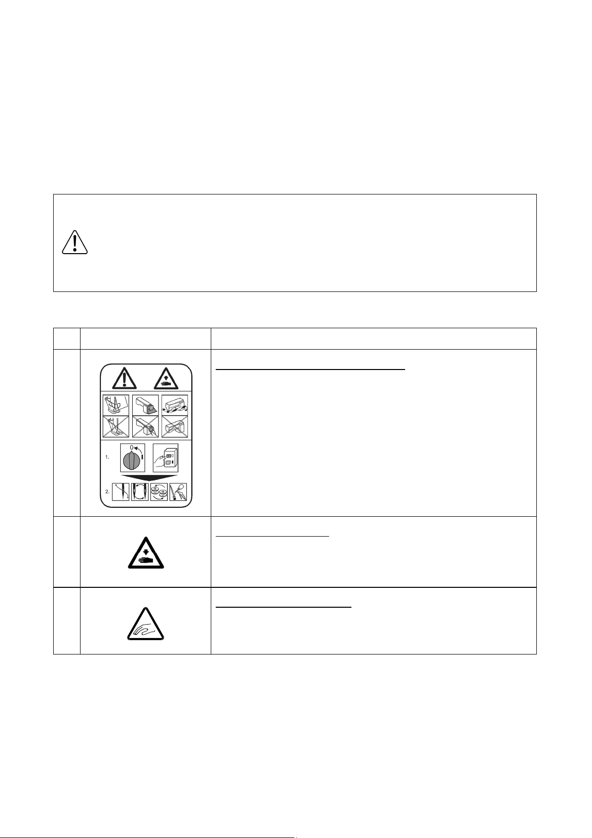
CAUTION INDICATIONS
No. Caution indication Description
1
Precaution for sewing machine operation
Indicates that removing the safety and operating the sewing
machine for some other purposes with power-on are prohibited.
z Please do not operate the sewing machine without
protective equipment such as a needle guard, an eye guard,
a belt cover or the others.
z Please turn off the power switch when threading, changing
a needle and a bobbin, cleaning, and lubricating.
:
2
3
Caution for fingers injury
Indicates a possibility of fingers (hands) injury in a certain
condition.
Caution for squeezing fingers
Indicates a possibility of squeezing fingers in a certain condition.
:
:
Page 3
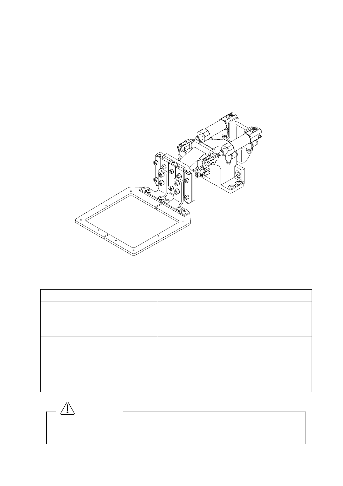
1. Features
The pneumatic type (left/right alternating) two-stage clamp separates the pressing operation into the
left and right sides. As each side can be operated with individual foot switches, this is suitable for
stitching two parts together. Usage methods can be changed to suit the purpose and make setup of the
stitching material more efficient. These methods include setting the left/right clamp operation order or
canceling the operation order and pressing with the side for which the foot switch is ON.
2. Specifications
Name
Applicable model:
Sewing area
Clamp UP position
Pressing operation
Drive source air
pressure
Primary side
Secondary side:
MP-G10-K2 (pneumatic type two stage clamp)
:
: PLK-G1010
: 100 (X) mm X 100 (Y) mm (same as PLK-1010)
: 30 mm
: Use foot switch (2-pedal) normally provided with the
electronic sewing machine and expansion foot
switch (1-pedal)
2
: 0.5 MPa(5 kg/cm
: 0.4 MPa(4 kg/cm
)or more
2
)
Trouble such as operation errors could occur if the secondary pressure is set too high.
Use within the range of 0.4 MPa (4 kg/cm
CAUTION
2
).
- 1 -
Page 4
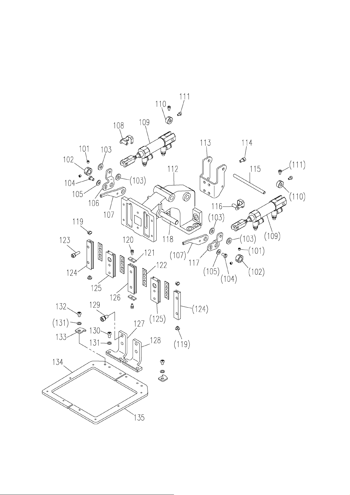
3. Configuration
★ The Fig. numbers in the drawing correspond to the part numbers given in the following explanations.
3.1 Clamp mechanism
- 2 -
Page 5

3.1 Clamp mechanism (Parts list)
Fig 部品コード 数量
No. Parts No.
101 M91055020 ロッカクアナツキトメネジ M4X4 Screw M4X4 4
102 MH10A0352 カラー Collar 2
103 M90519050
104 M91109002 ヒラネジ 11/64(40)X7 Screw 11/64(40)X7 2
105 M90421050 ザガネ 4 Washer 4 2
106 MH10K0950 レバー(S2L) Lever (S2L) 1
107 MH10K1950 レバー(S1) Lever (S1) 2
108 M90538060 ナックルピン(L) Knuckle pin (L) 1
109 ME10P0434 エアシリンダ Air cylinder 2
110 ME10P0352 カラー Collar 2
111 M93004021 ロッカクアナツキボルト M3X5 Socket bolt M3X5 4
112 MH10A0308 オサエダイ Clamp bracket 1
113 MH10K0601 シリンダトリツケイタ Cylinder bracket 1
114 M94002017 セフティソケット M4X8 Safety socket bolt M4X8 4
115 M90555060 ピン Pin 1
ナイロンワッシャ
品 名 Description
Amt. Req.
Nylon washer 4
116 M90548060 ナックルピン(R) Knuckle pin (R) 1
117 MH10K2950 レバー(S2R) Lever (S2R) 1
118 M90822060 ピン Pin 1
119 M90804003 マルヒラネジ 1/8(44)X4 Screw 1/8(44)X4 4
120 M94003017 セフティソケット M3X6 Safety socket bolt M3X6 2
121 MH10A4477 ストッパ Stopper 2
122 M94008070 ローラリテーナ Roller retainer 4
123 M94019017 セフティソケット M4X14 Safety socket bolt M4X14 6
124 MH10A2957 オサエコテイレース Fixed race 2
125 MH10A3957 オサエイドウレース Movable race 2
126 MH10A4957 オサエコテイレース Fixed race 1
127 MH10K0308 オサエトリツケイタ(L) Clamp foot (L) 1
128 MH10K1308 オサエトリツケイタ(R) Clamp foot (R) 1
129 M95005017 セフティソケット M5X10 Safety socket bolt M5X10 4
130 M94005022 ロッカクアナツキボタンボルト M4X8 Bolt M4X8 4
131 M90422050 コザガネ 4 Washer 4 6
132 M94041021 ロッカクアナツキボタンボルト M4X6 Bolt M4X6 2
133 MH10A0196 イチギメイタ Guide plate 2
134 MH10K0105 オサエ(L) Clamp frame (L) 1
135 MH10K1105 オサエ(R) Clamp frame (R) 1
- 3 -
Page 6

3.2 Pneumatic pressure control unit
3.3 Accessories
- 4 -
Page 7

3.2 Pneumatic pressure control unit (Parts list)
Fig 部品コード 数量
No. Parts No.
201 MB61A5601 デンジベントリツケイタ Valve mounting plate 1
202 M91066004 SW-PW プラマイナベネジ M4X25 Screw M4X25 4
203 MB10S0599 デンジベンクミタテ Solenoid valve assy 1
204 M90511050 ザガネ 5 Washer 5 2
205 M95003017 セフティソケット M5X8 Safety socket bolt M5X8 2
206 MB10B0508 セツゾクデンセンクミタテ(A) Cable assy (A) 1
207 MH10K0508 セツゾクデンセンクミタテ(B) Cable assy (B) 1
208 MA30A0964 レジューサ Reducer 4
209 MB10K0567 エアチューブクミタテ(A) Air tube assy (A) 1
210 MB10K1567 エアチューブクミタテ(B) Air tube assy (B) 1
211 MB10K2567 エアチューブクミタテ(C) Air tube assy (C) 1
212 MB10K3567 エアチューブクミタテ(D) Air tube assy (D) 1
213 M91035089 サイレンサ Muffler 2
214 MB20P1567 エアチューブ Air tube 1
215 ME40A0963 フィルタレギュレータ Filter regulator 1
品 名 Description
Amt. Req.
216 MA20A8571 L ガタワンタッチツギテ L-type quick joint 3
3.3 Accessories (Parts list)
Fig 部品コード 数量
No. Parts No.
301 MF06A1620 インシュロックタイ Cord tie 4
302 M94007099 ナイロンクリップ 6 Nylon clip 6 1
303 M91054004 SW-PW プラマイナベネジ M4X8 Screw M4X8 2
304 MB60A1620 ナイロンクリップ 8 Nylon clip 8 1
305 M90409041 マルモクネジ 4.5X20 Wooden screw 4.5X20 2
306 MH10K0691 パッキン Clamp pad 2
307 MH10K1691 パッキン Clamp pad 4
308 ME10P0691 パッキン Pad 1
309 MB10X0742 フタ Cap 1
310 M95018021 ロッカクアナツキボルト M4X8 Bolt M4X8 4
311 M91010089 ロッカクソケット Socket 1
品 名 Description
Amt. Req.
312 MA30A0571 ワンタッチツギテ Quick joint 1
313 MS06A0567 エアチューブ Air tube 1
314 MH10K0FSW フットスイッチ Foot switch 1
- 5 -
Page 8

4. Setup procedures
Always make sure that the power is OFF before starting setting work.
4.1 Installing the clamp drive mechanism
(1) Remove the four screws on the Y axis movement race side fixing the clamp base (Fig. No.112) and
the two screws on the axis support side, and remove the magnetic clamp mechanism mounted as
a standard on the sewing machine.
(2) Using the screws removed above, install this pneumatic clamp mechanism following the above step
in reverse. Make sure that the clamp is not inclined at this time.
(3) If there is no need to reinstall the magnetic clamp mounted as a standard on the sewing machine
after changing to the pneumatic type clamp, it is recommended to remove the drive mechanism
parts in the sewing machine head.
To remove these parts, refer to the part catalog P-246 for the PLK-G1010 sewing machine unit, and
remove the parts including Fig. No. H130 pin E, and Fig. No. H120 presser plate shown in the
catalog. Use the parts Fig.No.308, 309, and 310 enclosed with this attachment as a cover.
4.2 Installing the pneumatic pressure control related parts
CAUTION
(1) The regulator and solenoid valve assembly configured of Fig. No. 201, etc., are fixed to the bottom
of the sewing machine table with the enclosed Fig. No. 305 wood screws (two screws).
(2) Align the piping symbols of the Fig. No. 209, 210, 211 and 212 air tubes (φ4) with ports A to D on
the pneumatic two stage clamp's Fig. No. 109 air cylinder, and insert the tubes.
(3) Pass the air tubes through the notched section on the side of the sewing machine unit's motor cover,
and lead the tubes to the bottom of the table from the square hole on the table.
(4) Align the air tubes led out above with the ports A to D of the solenoid valve installed in step (1), and
insert the tubes.
(5) Bind the air tubes appropriately with the enclosed Fig. No. 301 Cord ties.
4.3 Connecting the switches and cables
(1) Remove the cover for the connector panel on the back of the sewing machine.
(2) Disconnect the cable connected to CON13 (FU) on the solenoid PCB. This cable is not used after
this attachment is mounted. Fix it where it will not obstruct the other electric parts.
(3) Lead out the Fig. No. 206 and 207 cables connected to the solenoid valve from the slot on the back
of the sewing machine table, pass through the cord bushing on the connector panel, and lead in to
the solenoid PCB side.
(4) Insert the Fig. No. 206 cable connector to CON13 (FU) on the PCB from where the cable was
disconnected above.
(5) Insert the Fig. No. 207 cable connector to CON15 (OP1) on the PCB.
(6) Connect the Fig. No. 314 foot switch (1-pedal) cable to the connector (12P) on the head of the
sewing machine. The green lead wire is the grounding wire. Connect this wire to the sewing
machine bed.
This completes the connection of the wiring. Check the connection with the following table, and
(7)
then securely install the cover removed from the connector panel.
- 6 -
Page 9

Signal name Connection
Existing
Input
Fig.No.206
Output
Work holder input 1 CON H - ③ on control unit
( I2 ) (foot switch already connected)
FSW
0V
CON H - ⑥ on control unit
(foot switch already connected)
Work holder input 2 Sewing machine head
( IF ) Connector (12P) -
Sewing machine head
Connector (12P) -
Fig.No.314
A
0V
Sewing machine head solenoid PCB
+24V
CON13 (FU) -
②
Work holder ouput 1 Sewing machine head solenoid PCB
Cable symbol
( O4 ) CON13 (FU) -
①
Sewing machine head solenoid PCB
+24V
CON15 (OP1) -
③
①
②
Red
White
White
Black
White
Black
White
Solenoid
valve
Solenoid
valve
Work holder output 2 Sewing machine head solenoid PCB
Fig.No.207
Cable symbol B
( OC ) CON15 (OP1) -
①
Black
4.4 Installing the system software
If the sewing machine is operated with the magnetic clamp settings, faults could occur.
Always install the setting disk for the pneumatic type clamp.
(1) Installing the System Software
① While holding down the [F] key on the front panel of the control box, turn the machine power ON.
(Keep pushing [F] key until red LED on the front panel is turned on.)
② [Model and language set function] screen is displayed.
③ Press the . Select the on the language set function screen then, press
the .
④ Press the . Select the on the model set function screen then, press
the .
⑤ Press the to determine the settings.
⑥ After [INITIALIZES SET VALUE] message is displayed, press the .
CAUTION
This completes installing the system software. Turn off the power switch once.
- 7 -
Page 10

(2) Points changed in setting details
The settings will be changed as shown below when the above setting desk is installed.
Mode
Clamp FN 2 1 Setting for valid number of clamp
Function
name
G1010K2 G1010 Remarks
Input/output
setting
Input/output
setting
O4 66H 33
O5 66H 33
Set this when changing from the magnetic
clamp to the pneumatic clamp.
Set this when changing from the magnetic
clamp to the pneumatic clamp.
4.5 Setting the clamp priority order
As the default, the left/right work clamp is set to operate randomly when the foot switch is turned ON.
To use this attachment so that the left clamp is lowered and then the right clamp is lowered, change the
settings with the following procedures after installing the system software.
When this method is set, the operation will start with the left clamp, so turn the left clamp foot switch
(2-pedal) [black] side ON. If the right clamp foot switch (1-pedal) is turned ON, neither the left nor right
clamp will operate.
(1) Press the on the standard screen to open the MENU mode.
(2) Press the in the menu icon. The Program Mode [Mode Selection] screen is displayed.
(3) Press the .
(4) The program Mode [Set Selection] is displayed.
(5) Set the clamp priority order. Press the [Priority of clamp mode].
(6) Change the priority order invalid display on the screen to valid , and the press
the .
(7) Press the on the screen.
(8) Then screen return to the [Mode Selection]. Press the .
This completes the setting of the [clamp priority order].
- 8 -
Page 11

5. Operation
5.1 Confirming operation
(1) Turn the sewing machine power switch ON.
(2) Confirm that the left and right work clamps lower when the foot switch (2-pedal) [Black] side and the
expanded foot switch (1-pedal) are turned ON, and rise when the switches are turned ON again.
(3) Lower the left and right work clamps, and press on the operation panel. Return to home will
start.
(4) Next, check that the positional relation of the clamp and needle hole center is at the scale shown in
the drawing. If the positions are deviated, refer to the PLK-G1010 Sewing Machine Head version
instruction manual and adjust the home.
5.2 Stitching test
(1) Select the stitching pattern. (Refer to the PLK-G1010 Sewing Machine Head version instruction
manual.)
(2) Press the [Black] side on the 2-pedal foot switch and the 1-pedal foot switch, and lower the left
and right work clamps. Next, press the [Gray] side on the foot switch to rotate the sewing
machine and start stitching. (Stitching will not start unless the left and right work clamps are
lowered.)
(3) When stitching is completed, the sewing machine will automatically return to home, and the
clamps will rise.
- 9 -
Page 12

MITSUBISHI ELECTRIC CORPORATION
FACTORY AUTOMATION SYSTEM GROUP
2-7-3, Marunouchi Chiyoda-ku Tokyo 100-8310, Japan
Fax : +81-3-3218-6821
New publication, effective SEP.2008
Contents subject to change without notice
 Loading...