

Page 1
MIRAGE
OWNER’S MANUAL
MIRAGE - EN-UK - OA0X13E4
MIRAGE - EN-UK - OA0X13E4
Page 2
Foreword
E09200104601
Thank you for selecting a MIRAGE as your new vehicle.
This owner’s manual will add to your understanding and full enjoyment of
the many fine features of this vehicle.
It contains information prepared to acquaint you with the proper way to operate and maintain your vehicle for the utmost in driving pleasure.
MITSUBISHI MOTORS Europe B.V. reserves the right to make changes in
design and specifications and/or to make additions to or improvements in
this product without obligation to install them on products previously manufactured.
It is an absolute requirement for the driver to strictly observe all laws and regulations concerning vehicles.
This owner’s manual has been written in compliance with such laws and regulations, but some of the contents may become contradictory with later amendment of the laws and regulations.
Please leave this owner’s manual in this vehicle at time of resale. The next
owner will appreciate having access to the information contained in this owner’s manual.
Repairs to your vehicle:
Vehicles in the warranty period:
All warranty repairs must be carried out by a MITSUBISHI MOTORS Authorized Service Point.
Vehicles outside the warranty period:
Where the vehicle is repaired is at the discretion of the owner.
Throughout this owner’s manual the words WARNING and CAUTION ap-
pear.
These serve as reminders to be especially careful. Failure to follow instructions could result in personal injury or damage to your vehicle.
WARNING
indicates a strong possibility of severe personal injury or death if instructions are not followed.
CAUTION
means hazards or unsafe practices that could cause minor personal injury or damage to your vehicle.
You will see another important symbol:
NOTE: gives helpful information.
*: indicates optional equipment.
It may differ according to the sales classification; refer
to the sales catalogue.
Abbreviations used in this owner’s manual:
LHD: Left-Hand Drive
RHD: Right-Hand Drive
M/T: Manual Transmission
CVT: Continuously Variable Transmission
Information for station service
E09300102842
Fuel
Fuel tank capacity 35 litres
Fuel requirements
Unleaded petrol octane number (EN228)
95 RON or higher
Refer to the “General information” section for the fuel selection.
Engine oil Refer to the “Maintenance” section for the selection of engine oil.
Tyre inflation pressure Refer to the “Maintenance” section for the tyre inflation pressure.
© 2012 Mitsubishi Motors Corporation
13
OA0X13E4
BLC-13-001351
Page 3

Table of contents
Overview/Quick guide
General information
Locking and unlocking 1
Seat and seat belts 2
Instruments and controls 3
Starting and driving 4
For pleasant driving 5
For emergencies 6
Vehicle care 7
OA0X13E4
Maintenance 8
Specifications 9
Page 4
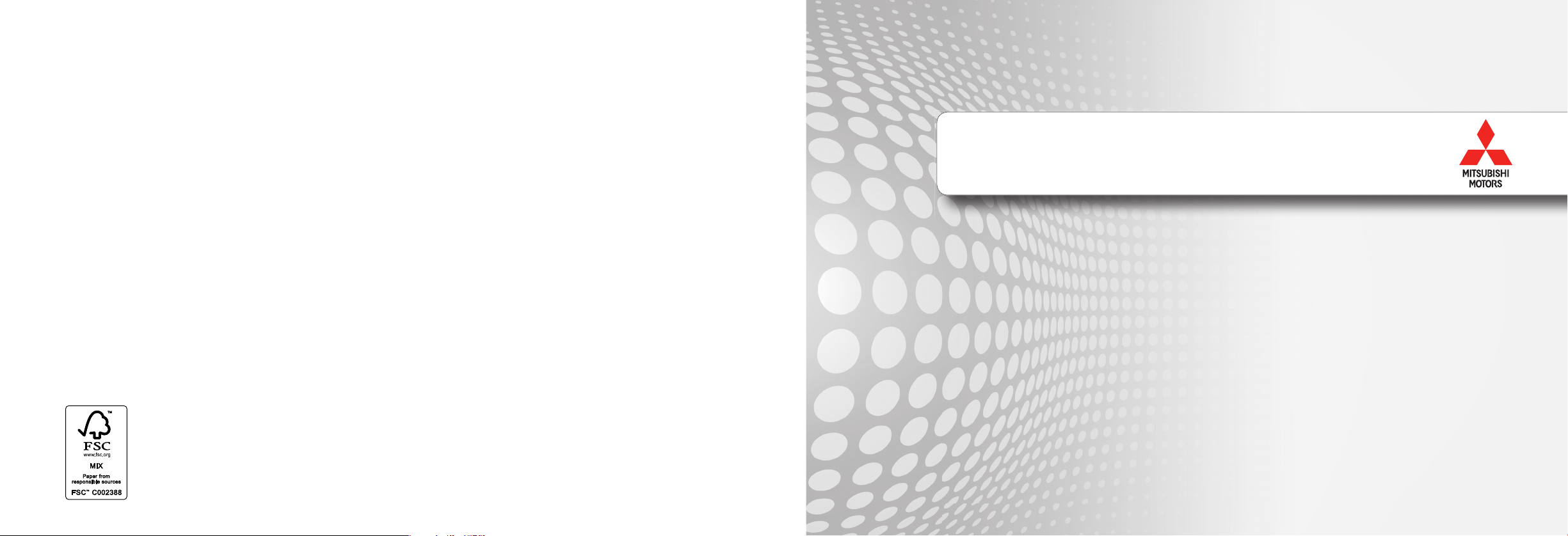
LHD
Overview/Quick guide
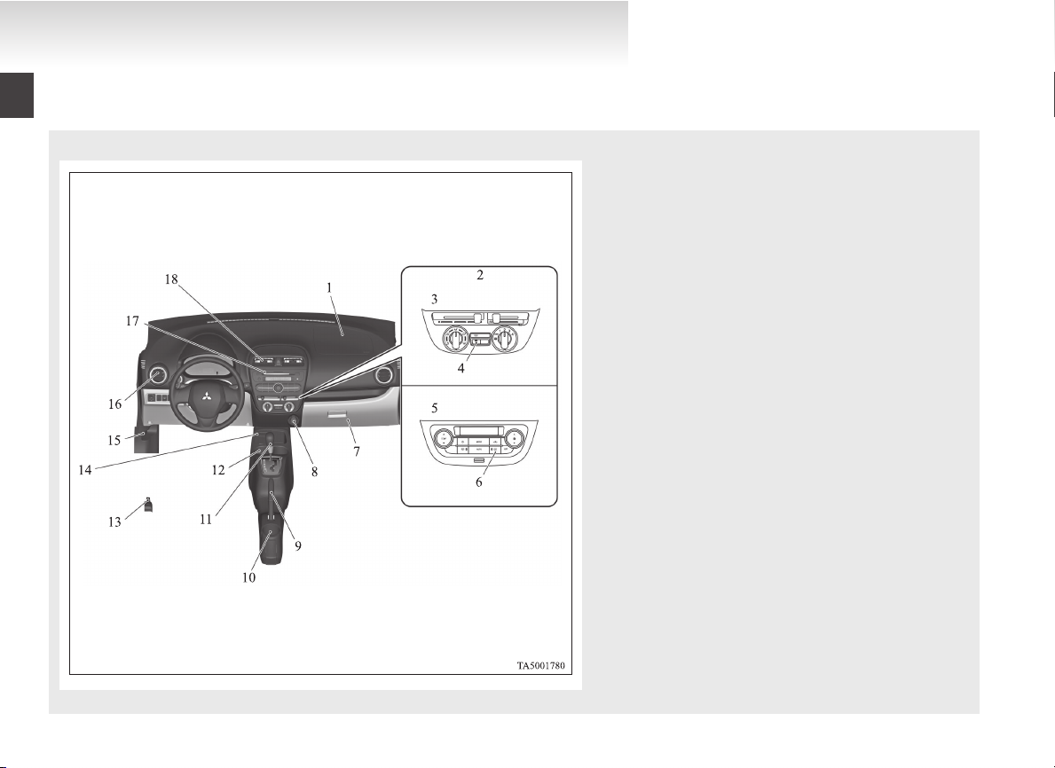
Instruments and controls
1. Instruments p. 3-02
2. Hazard warning flasher switch p. 3-18
3. Windscreen wiper and washer switch p. 3-19
4. Ignition switch* p. 4-08
5. Supplemental restraint system (SRS) -airbag (for driver) p. 2-17
6. Steering wheel height adjustment p. 4-06
7. Auto Stop & Go (AS&G) OFF switch* p. 4-18
8. Headlamp levelling switch p. 3-16
9. Fuse box p. 8-15
10. Electric remote-controlled outside rear-view mirror
11. Engine switch* p. 4-09
12. Combination headlamps and dipper switch p. 3-14
E08500100074
Rear window wiper and washer switch p. 3-22
Horn switch p. 3-24
switch* p. 4-07
Turn-signal lever p. 3-17
Front fog lamp switch* p. 3-18
Rear fog lamp switch p. 3-18
OA0X13E4
Page 5
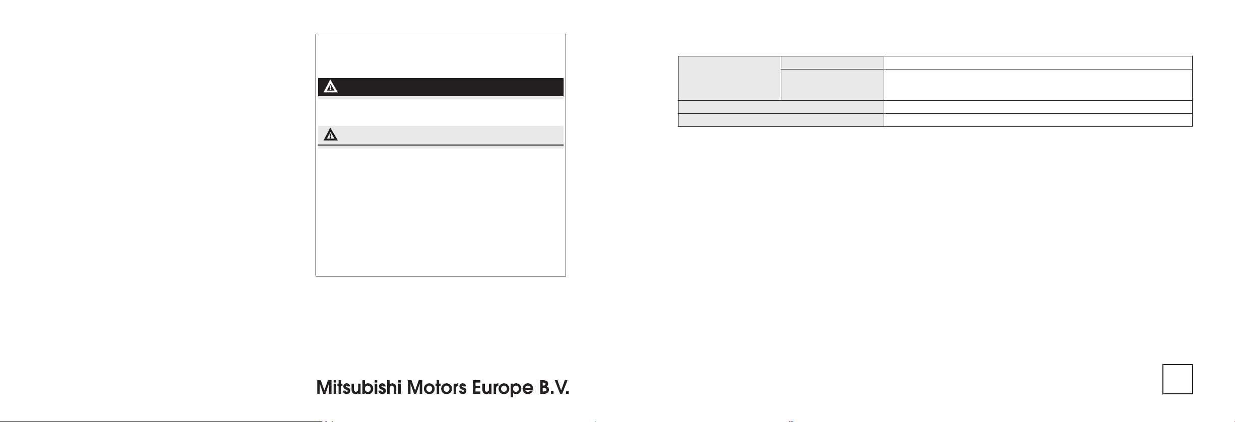
RHD
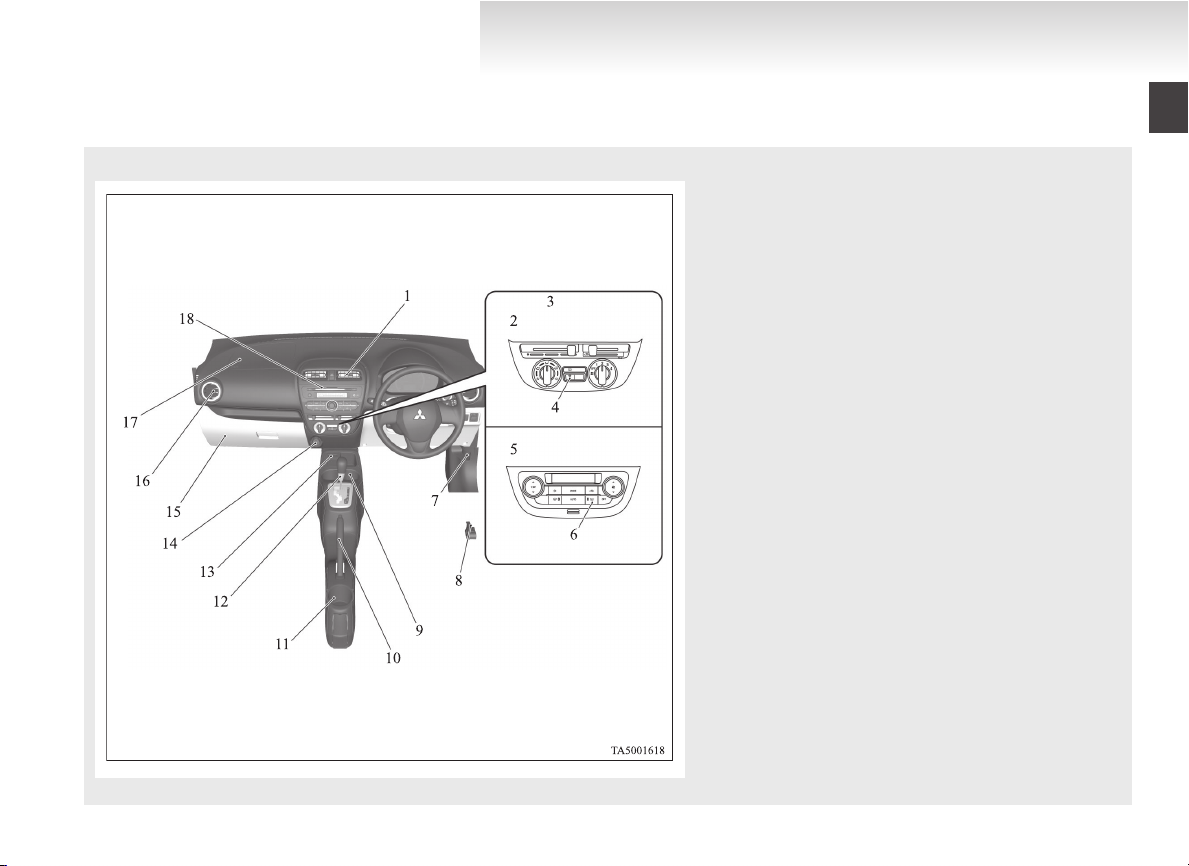
Overview/Quick guide
1. Instruments p. 3-02
2. Windscreen wiper and washer switch p. 3-19
Rear window wiper and washer switch p. 3-22
3. Engine switch* p. 4-09
4. Headlamp levelling switch p. 3-16
5. Electric remote-controlled outside rear-view mirror
switch* p. 4-07
6. Auto Stop & Go (AS&G) OFF switch* p. 4-18
7. Ignition switch* p. 4-08
8. Supplemental restraint system (SRS) -airbag (for driver) p. 2-17
Horn switch p. 3-24
9. Combination headlamps and dipper switch p. 3-14
Turn-signal lever p. 3-17
Front fog lamp switch* p. 3-18
Rear fog lamp switch p. 3-18
10. Hazard warning flasher switch p. 3-18
OA0X13E4
Page 6
LHD
Overview/Quick guide
1. Supplemental restraint system (SRS)-airbag (for front passenger) p. 2-17
2. Heater* p. 5-03
3. Manual air conditioning* p. 5-03
4. Rear window demister switch p. 3-23
5. Automatic air conditioning* p. 5-06
6. Rear window demister switch p. 3-23
7. Glove box p. 5-36
8. Accessory socket p. 5-35
9. Parking brake lever p. 4-04
10. Cup holder (for the rear seat) p. 5-37
11. Gearshift lever* p. 4-19
Selector lever* p. 4-21
12. Cup holder (for the front seat) p. 5-37
13. Fuel tank filler door release lever p. 02
14. Key slot* p. 4-14
15. Bonnet release lever p. 8-04
16. Side ventilators p. 5-02
17. Audio* p. 5-13
MITSUBISHI Multi Entertainment System*
Refer to the separate “MITSUBISHI Multi Entertainment System
owner’s manual”
Digital clock* p. 5-20
18. Centre ventilators p. 5-02
OA0X13E4
Page 7
RHD
Overview/Quick guide
1. Centre ventilators p. 5-02
2. Manual air conditioning* p. 5-03
3. Heater* p. 5-03
4. Rear window demister switch p. 3-23
5. Automatic air conditioning* p. 5-06
6. Rear window demister switch p. 3-23
7. Bonnet release lever p. 8-04
8. Fuel tank filler door release lever p. 02
9. Cup holder (for the front seat) p. 5-37
10. Parking brake lever p. 4-04
11. Cup holder (for the rear seat) p. 5-37
12. Gearshift lever* p. 4-19
Selector lever* p. 4-21
13. Key slot* p. 4-14
14. Accessory socket p. 5-35
15. Glove box p. 5-36
16. Side ventilators p. 5-02
17. Supplemental restraint system (SRS)-airbag (for front passenger) p. 2-17
18. Audio* p. 5-13
MITSUBISHI Multi Entertainment System*
Refer to the separate “MITSUBISHI Multi Entertainment System
owner’s manual”
Digital clock* p. 5-20
OA0X13E4
Page 8

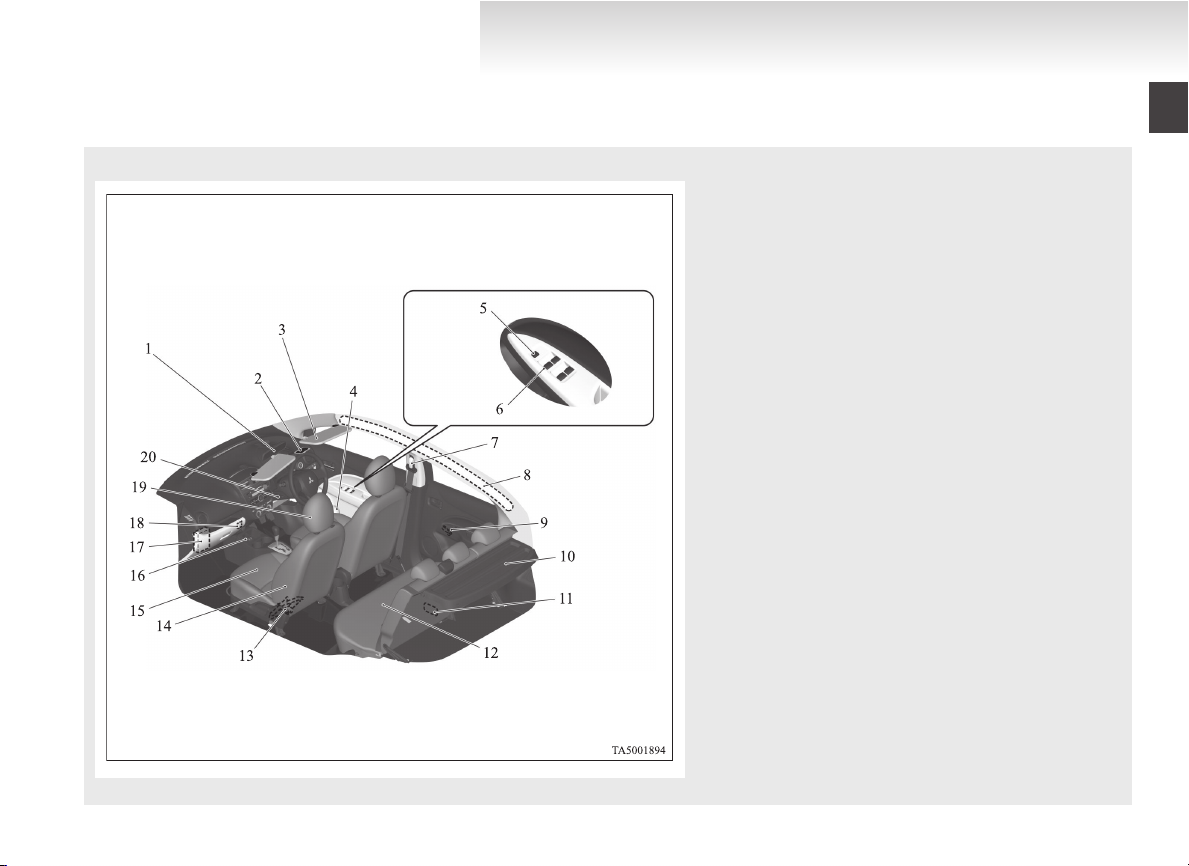
LHD
Overview/Quick guide
Interior
E08500200075
1. Sun visors p. 5-34
Vanity mirror p. 5-34
Card holder p. 5-34
2. Bottle holder p. 5-38
3. Room lamp p. 5-35, 8-21
4. Inside rear-view mirror p. 4-06
5. Head restraints p. 2-04
6. USB input terminal* p. 5-31
7. Heated seat switches* p. 2-03
8. Front seat p. 2-02
9. Supplemental restraint system (SRS) - side airbag (for front
seat) p. 2-23
10. Jack* p. 6-05
11. Rear seat p. 2-03
12. Rear shelf panel* p. 5-38
13. Luggage room lamp* p. 5-36, 8-21
14. Manual window control* p. 1-15
15. Supplemental restraint system (SRS) - curtain airbag p. 2-23
16. Seat belts p. 2-05
Adjustable seat belt anchor* p. 2-07
17. Electric window control switch* p. 1-15
18. Electric window lock switch* p. 1-16
OA0X13E4
Page 9
RHD
Overview/Quick guide
1. Inside rear-view mirror p. 4-06
2. Room lamp p. 5-35, 8-21
3. Sun visors p. 5-34
Vanity mirror p. 5-34
Card holder p. 5-34
4. Bottle holder p. 5-38
5. Electric window lock switch* p. 1-16
6. Electric window control switch* p. 1-15
7. Seat belts p. 2-05
Adjustable seat belt anchor* p. 2-07
8. Supplemental restraint system (SRS) - curtain airbag p. 2-23
9. Manual window control* p. 1-15
10. Rear shelf panel* p. 5-38
11. Luggage room lamp* p. 5-36, 8-21
12. Rear seat p. 2-03
13. Jack* p. 6-05
14. Supplemental restraint system (SRS) - side airbag (for front
seat) p. 2-23
15. Front seat p. 2-02
16. Heated seat switches* p. 2-03
17. Fuse box p. 8-15
18. USB input terminal* p. 5-31
19. Head restraints p. 2-04
20. Steering wheel height adjustment p. 4-06
OA0X13E4
Page 10
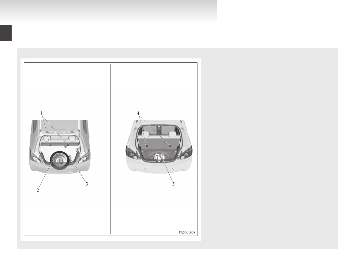
Type 1 Type 2
Overview/Quick guide
Luggage area
E08500300047
1. Tether anchorages for child restraint system p. 2-15
2. Spare wheel p. 6-12
3. Tools p. 6-05
4. Tether anchorages for child restraint system p. 2-15
5. Tools p. 6-05
Tyre repair kit p. 6-06
OA0X13E4
Page 11
Overview/Quick guide
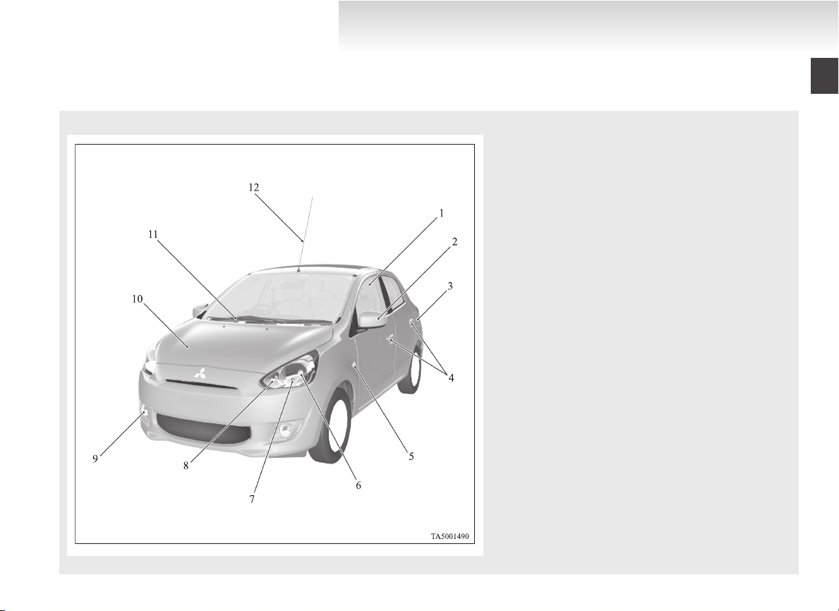
Outside (Front)
E08500400107
1. Electric window control* p. 1-15
2. Outside rear-view mirror p. 4-07
3. Fuel tank filler p. 02
4. Locking and unlocking the doors p. 1-12
Keyless entry system* p. 1-03
Keyless operation system* p. 1-04
5. Side turn-signal lamps p. 3-17, 8-20
6. Headlamps p. 3-14, 8-20, 8-21
7. Position lamps p. 3-14, 8-20, 8-21
8. Front turn-signal lamps p. 3-17, 8-20, 8-21
9. Front fog lamps* p. 3-18, 8-20, 8-22
Daytime running lamps* p. 8-20, 8-22
10. Engine compartment p. 8-02, 9-13
Bonnet p. 8-04
11. Windscreen wiper and washer p. 3-19
12. Antenna p. 5-30
OA0X13E4
Page 12
Overview/Quick guide
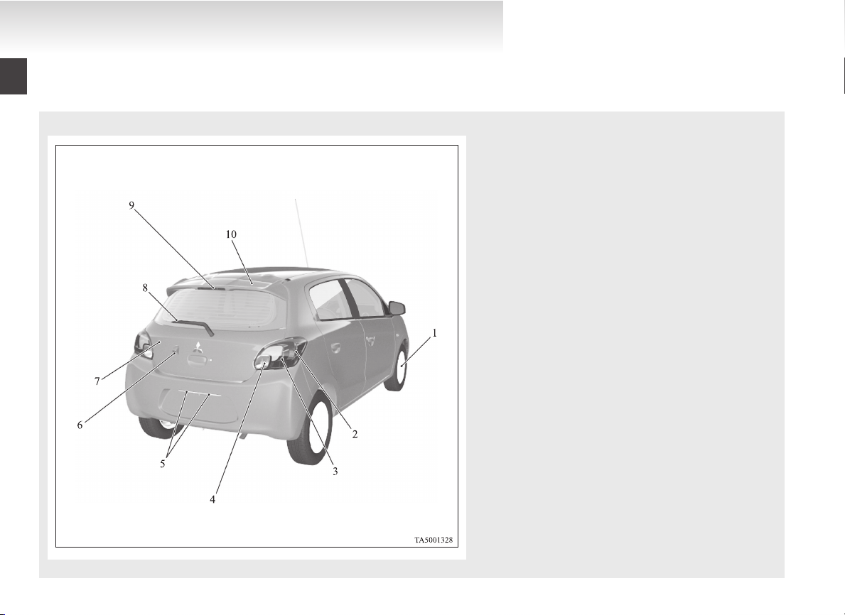
Outside (Rear)
E08500400123
1. Tyre p. 8-09
Tyre inflation pressures p. 8-10
Wheel condition p. 8-11
Tyre rotation p. 8-11
Snow traction device (Tyre chains) p. 8-12
Size of tyres and wheels p. 9-10
2. Stop and tail lamps p. 8-20, 8-23
3. Rear turn-signal lamps p. 3-17, 8-20, 8-23
4. Reversing lamps (passenger’s side) p. 8-20, 8-23
Rear fog lamp (driver’s side) p. 8-20, 8-23
5. Licence plate lamps p. 8-20, 8-24
6. Rear-view camera* p. 4-32
7. Tailgate p. 1-14
8. Rear window wiper and washer p. 3-22
9. High-mounted stop lamp* p. 8-20, 8-24
10. Rear spoiler*
OA0X13E4
Page 13
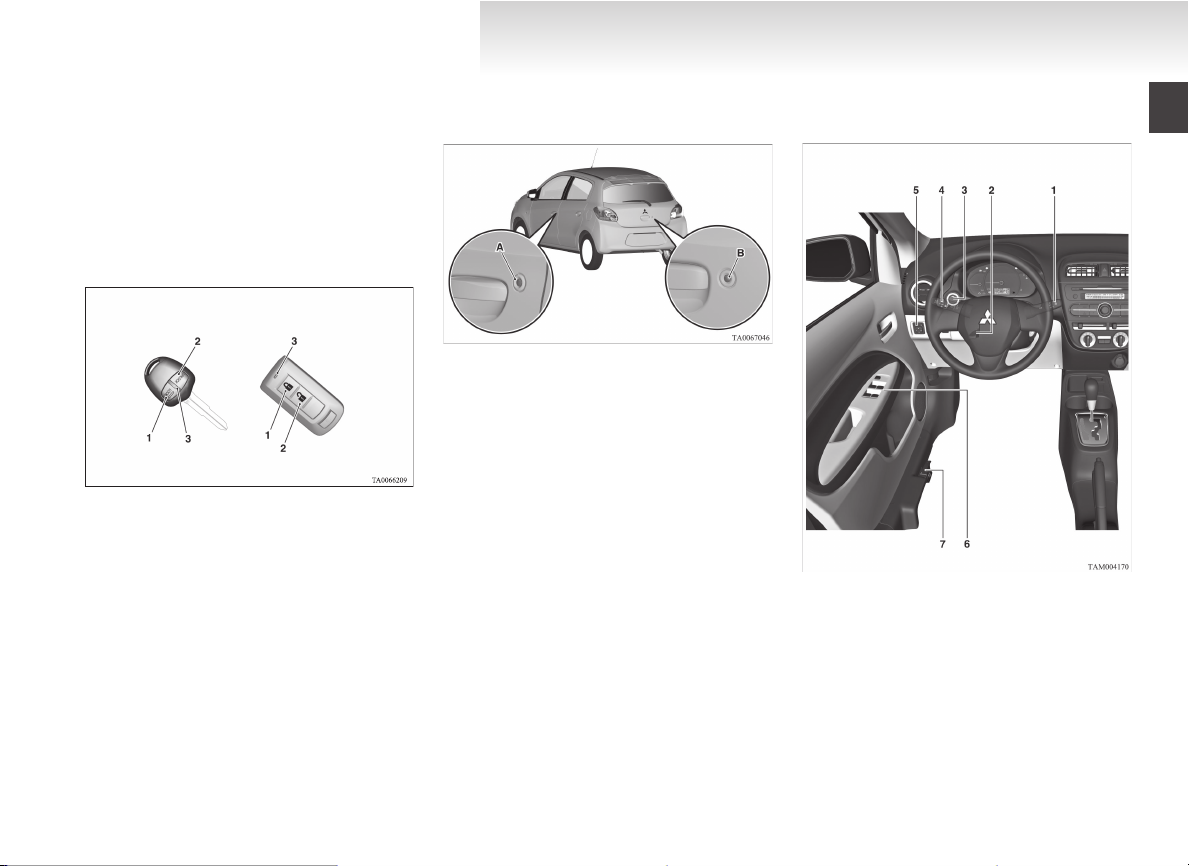
Keyless entry keyKeyless operation key
LHD
Quick guide
Lock and unlock the doors and tailgate
E08500500010
E08500600040
Keyless entry system*
Press the remote control switch, and all doors and
the tailgate will be locked or unlocked as desired.
The remote control switch will operate within approximately 4 m from the vehicle.
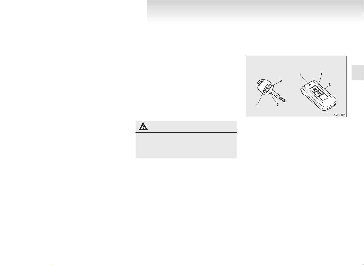
1- LOCK switch
2- UNLOCK switch
3- Indication lamp
Refer to “Keyless entry system*” on page 1-03.
Keyless operation system*
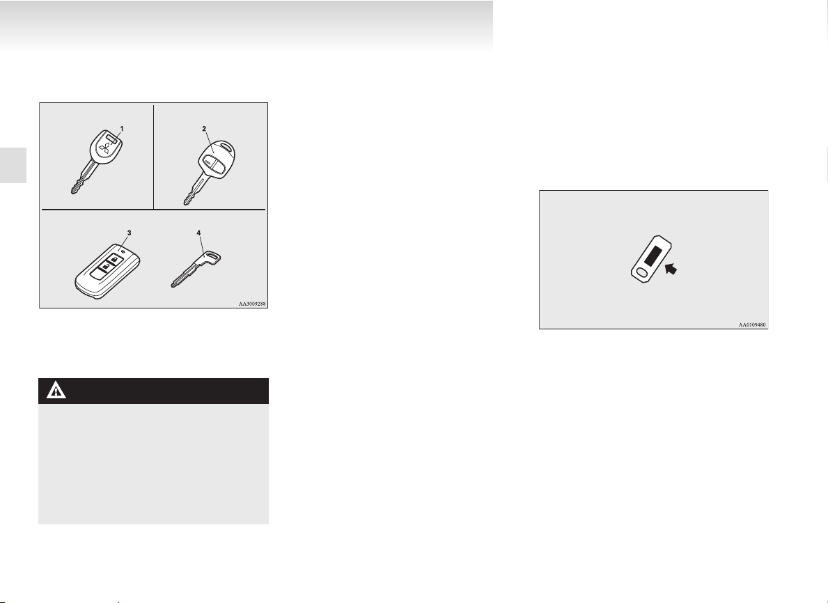
When you are carrying the keyless operation key,
if you press the driver’s door switch (A), or the tailgate switch (B) within the operating range, the
doors and the tailgate are locked/unlocked.
The operating range is approximately 70 cm from
the driver’s door switch and the tailgate switch.
Refer to “Keyless operation system*” on page
1-04.
Overview/Quick guide
Around the driver’s seat
E08500800068
OA0X13E4
Page 14
RHD
LHD
Overview/Quick guide
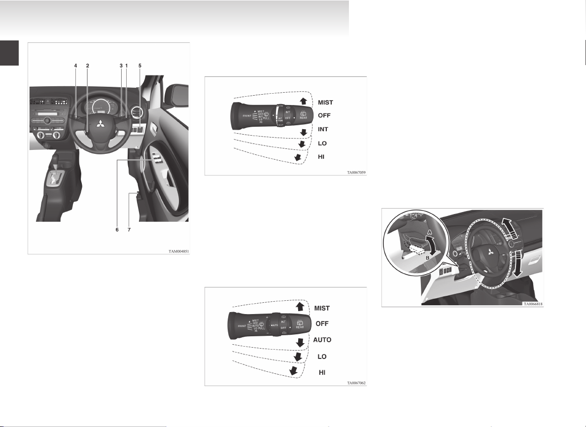
1-Wiper and washer switch
Except for vehicles equipped with rain sensor
MIST- Misting function
The wipers will operate once.
OFF- Off
AUTO- Auto-wiper control
Rain sensor
The wipers will automatically operate depending on the degree of wetness on the windscreen.
LO- Slow
HI- Fast
The washer fluid will be sprayed onto the windscreen by pulling the lever towards you.
Refer “Wiper and washer switch” on page 3-19.
MIST- Misting function
2-Steering wheel height adjustment
The wipers will operate once.
OFF- Off
INT- Intermittent (Speed sensitive)
LO- Slow
HI- Fast
Vehicles with rain sensor
OA0X13E4
Page 15
RHD
A- Locked
B- Release
1. Release the lever while holding the steering
wheel up.
2. Adjust the steering wheel to the desired position.
3. Securely lock the steering wheel by pulling
the lever fully upward.
Refer “Steering wheel height adjustment” on
page 4-06.
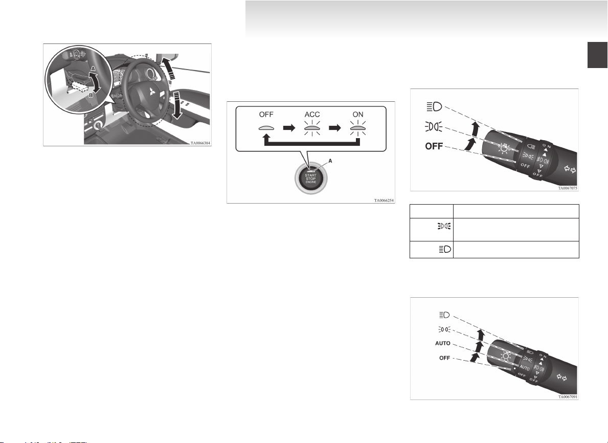
3-Engine switch*
[For vehicles equipped with keyless operation system]
If you are carrying the keyless operation key, you
can start the engine. If you press the engine switch
without depressing the brake pedal (CVT) or the
clutch pedal (M/T), you can change the operation
mode in the order of OFF, ACC, ON, OFF.
OFF- The indication lamp (A) on the en-
gine switch turns off.
ACC- The indication lamp on the engine
switch illuminates orange.
ON- The indication lamp on the engine
switch illuminates green.
Refer “Engine switch” on page 4-09.
Overview/Quick guide
4-Combination headlamps
Type 1
Rotate the switch to turn on the lamps.
OFF All lamps off
Position, tail, licence plate and instrument panel lamps on
Headlamps and other lamps go on
Rotate the switch to turn on the lamps.
Type 2
OA0X13E4
Page 16
Driver’s switch (Type 1)
Driver’s switch (Type 2) Driver’s switch (Type 3)
Overview/Quick guide
OFF All lamps off
AUTO With the ignition switch or the oper-
ation mode is in ON, head-lamps, position, tail, licence plate, and instrument panel lamps turn on and off automatically in accordance with outside light level. All lamps turn off automatically when the ignition switch
is turned to “OFF” position or the operation mode is put in OFF.
Position, tail, licence plate and instrument panel lamps on
Headlamps and other lamps go on
Refer “Combination headlamps and dipper
switch” on page 3-14.
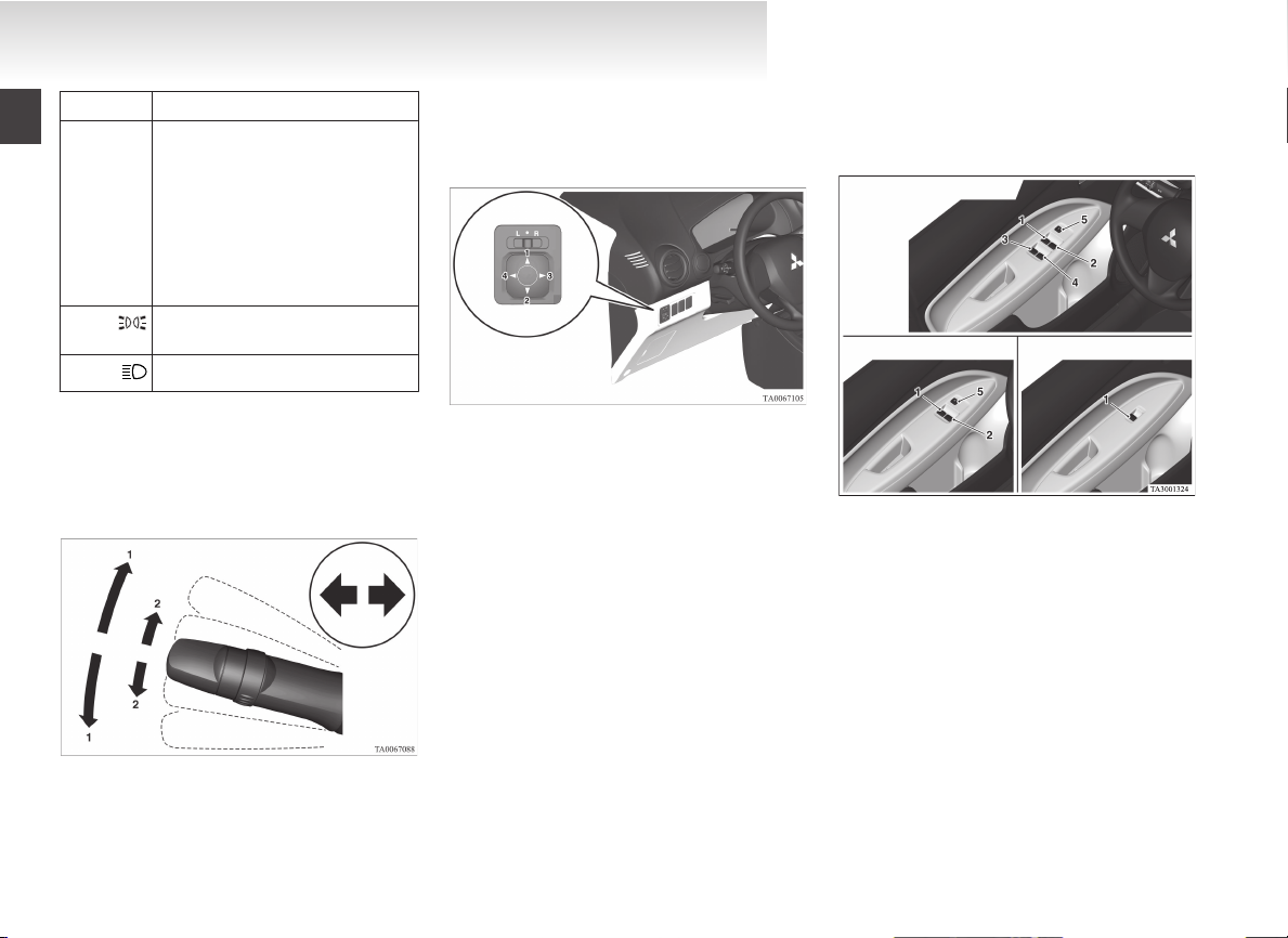
4-Turn-signal lever
The turn-signal lamps flash when the lever is operated
1- Turn-signals
2- Lane-change signals
Refer “Turn-signal lever” on page 3-17.
5-Electric remote-controlled outside rear-view mirrors*
To adjust the mirror position
L- Left outside mirror adjustment
R- Right outside mirror adjustment
1- Up
2- Down
3- Right
4- Left
Refer “Electric remote-controlled outside rearview mirrors” on page 4-07.
6-Electric window control*
Press the switch down for opening the window,
and pull the switch for closing.
1- Driver’s door window
2- Front passenger’s door window
3- Rear left door window
4- Rear right door window
5- Lock switch
Lock switch (Type 1 and 2)
If you press the switch (5), the passenger’s
switches cannot be operated. To cancel, press it
once again.
Refer “Electric window control” on page 1-15.
7-Fuel tank filler door release lever
Open the fuel tank filler door.
OA0X13E4
Page 17
LHD
RHD
The fuel tank filler is located on the rear left side of
your vehicle.
Refer “Filling the fuel tank” on page 02.
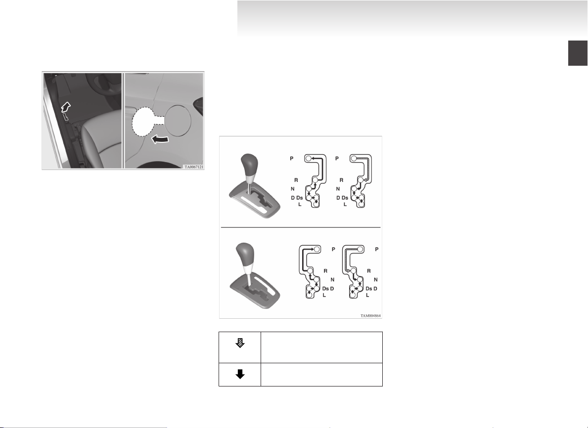
Automatic transmission INVECS-III CVT (Intelligent & Innovative Vehicle Electronic Control System III)*
Selector lever operation
The CVT selects an optimum gear ratio automatically, depending on the speed of the vehicle and
the position of the accelerator pedal.
E08501000054
Overview/Quick guide
Selector lever positions
“P” PARK
This position locks the transmission to prevent the
vehicle from moving. The engine can be started in
this position.
“R” REVERSE
This position is to back up.
“N” NEUTRAL
At this position the transmission is disengaged.
“D” DRIVE
This position is used for most city and highway driving.
“Ds” (DOWNSHIFT & SPORTY DRIVING)
Use when engine braking is needed, or for highpower sport drive.
“L” (LOW)
This position is for driving up very steep hills and
for engine braking at low speeds when driving
down steep hills.
Refer to “Automatic transmission INVECS-III
CVT (Intelligent & Innovative Vehicle Electronic Control System III)” on page 4-21.
While depressing the brake pedal,
move the selector lever through the
gate.
Move the selector lever through the
gate.
OA0X13E4
Page 18
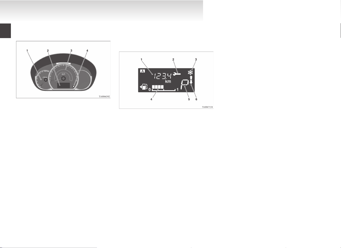
Overview/Quick guide
Instruments
1- Tachometer*
The tachometer indicates the engine speed
(r/min). The tachometer helps you to obtain
more economical driving and also warns you
of excessive engine speeds (Red zone).
2- Multi-information display
3- Speedometer (km/h or mph + km/h)
4- Multi-information display switch
E08501100039
The following information is included on the multiinformation display: odometer, tripmeter, meter illumination control, service reminder, fuel remaining, driving range and average fuel consumption, etc.
1- Information display
2- Service reminder
3- Frozen road warning*
4- Fuel remaining display
5- Selector lever position display*
6- Gearshift indicator*
Refer to “Instruments” on page 3-02.
Multi-information display
Always stop the vehicle in a safe place before operating.
Refer to “Multi-information display” on page
3-02.
OA0X13E4
Page 19
Overview/Quick guide
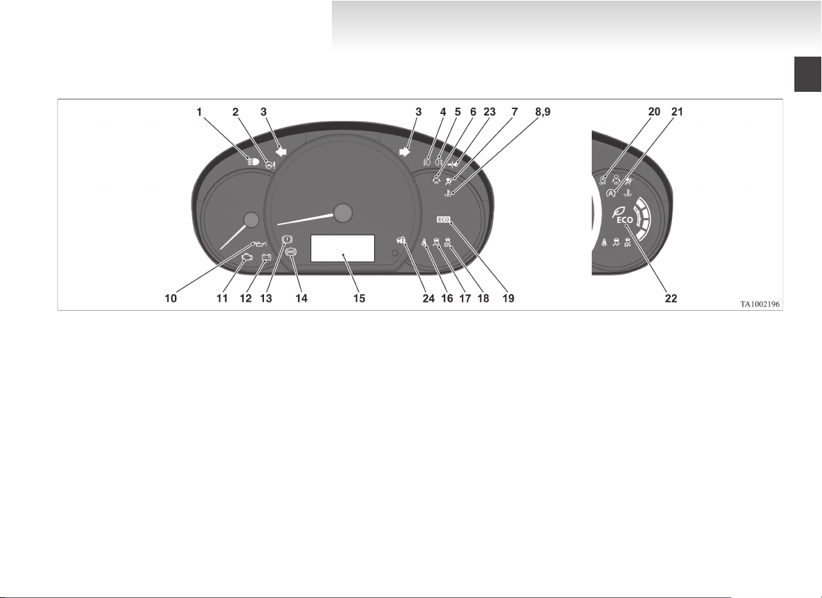
Indication and warning lamps
1-
High-beam indication lamp ® p. 3-11
2-
Electric power steering system (EPS) warning lamp ® p. 4-30
3-
Turn-signal indication lamps/Hazard warning indication lamps ® p. 3-11
4-
Front fog lamp indication lamp* ® p. 3-11
5-
Rear fog lamp indication lamp ® p. 3-11
6-
Door ajar warning lamp ® p. 3-14
7-
Supplement Restraint System (SRS) warning lamp ® p. 2-25
8-
High coolant temperature warning lamp (red) ® p. 3-13
9-
Low coolant temperature indication lamp (green) ® p. 3-11
10-
Oil pressure warning lamp ® p. 3-13
11-
Check engine warning lamp ® p. 3-12
12-
Charge warning lamp ® p. 3-13
13-
Brake warning lamp ® p. 3-12
14-
Anti-lock brake system (ABS) warning lamp ® p. 4-28
15-
Multi-information display ® p. 3-02
16-
Seat belt warning lamp ® p. 2-06
17-
Active Stability Control (ASC) indication lamp ® p. 4-31
18-
Active Stability Control (ASC) OFF indication lamp ® p. 4-31
19-
ECO indication lamp* ® p. 3-11
20-
Auto Stop & Go (AS&G) OFF indication lamp* ® p. 4-18
21-
Auto Stop & Go (AS&G) indication lamp* ® p. 4-15
22-
ECO drive assist* ® p. 3-11
23- For details, refer to “Warning activator” on page 1-09.
(if so equipped)
24- For details, refer to “Warning activator” on page 1-09.
(if so equipped)
E08501300044
OA0X13E4
Page 20

OA0X13E4
Page 21

General information
Fuel selection...................................................................................02
Filling the fuel tank..........................................................................02
Installation of accessories................................................................04
Modification/alterations to the electrical or fuel systems................04
Genuine parts...................................................................................05
Safety and disposal information for used engine oil........................05
Disposal information for used batteries...........................................05
OA0X13E4
Page 22
General information
Fuel selection
Recommended
fuel
Unleaded petrol octane number
(EN228)
95 RON or higher
CAUTION
The use of leaded fuel can result in seri-
l
ous damage to the engine and catalytic
converter. Do not use leaded fuel.
NOTE
Your vehicles have the knock control system
l
so that you can use unleaded petrol 90 RON
as an emergent measure in case unleaded pet-
rol 95 RON or higher is not available on jour-
ney, etc.
In such a case, you don’t need to adjust the
engine specially. In case of using unleaded
petrol 90 RON, the engine performance level
is reduced.
E00200103249
Repeatedly driving short distances at low
l
speeds can cause deposits to form in the fuel
system and engine, resulting in poor starting
and poor acceleration. If these problems occur, you are advised to add a detergent additive to the gasoline when you refuel the vehicle. The additive will remove the deposits,
thereby returning the engine to a normal condition. Be sure to use a MITSUBISHI
MOTORS GENUINE FUEL SYSTEM
CLEANER. Using an unsuitable additive
could make the engine malfunction. For details, please contact a MITSUBISHI
MOTORS Authorized Service Point.
Poor quality petrol can cause problems such
l
as difficult starting, stalling, engine noise
and hesitation. If you experience these problems, try another brand and/or grade of petrol.
If the check engine warning lamp flashes,
have the system checked as soon as possible
at a MITSUBISHI MOTORS Authorized
Service Point.
E10 type petrol
The petrol engines are compatible with the E10
type petrol (containing 10 % ethanol) conforming
to European standards EN 228.
E00203200019
CAUTION
Do not use more than 10 % concentration
l
of ethanol (grain alcohol) by volume.
Use of more than 10 % concentration
may lead to damage to your vehicle fuel
system, engine, engine sensors and exhaust system.
Filling the fuel tank
WARNING
When handling fuel, comply with the safe-
l
ty regulations displayed by garages and
filling stations.
Gasoline is highly flammable and explo-
l
sive. You could be burned or seriously injured when handling it. When refueling
your vehicle, always turn the engine off
and keep away from flames, sparks, and
smoking materials. Always handle fuel in
well-ventilated outdoor areas.
Before removing the fuel cap, be sure to
l
get rid of your body’s static electricity by
touching a metal part of the car or the
fuel pump. Any static electricity on your
body could create a spark that ignites
fuel vapour.
Perform the whole refueling process
l
(opening the fuel tank filler door, removing the fuel cap, etc.) by yourself. Do not
let any other person come near the fuel
tank filler. If you allowed a person to
help you and that person was carrying
static electricity, fuel vapour could be ignited.
Do not move away from the fuel tank fill-
l
er until refueling is finished. If you
moved away and did something else (for
example, sitting on a seat) partway
through the refueling process, you could
pick up a fresh charge of static electricity.
If the tank cap must be replaced, use only
l
a MITSUBISHI MOTORS original part.
E00200202575
02
OA0X13E4
Page 23
Fuel tank capacity
35 litres
Refueling
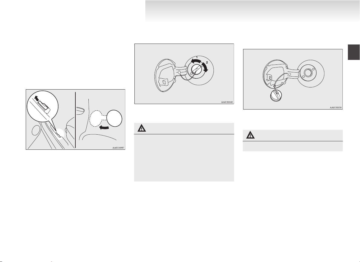
1. Before filling with fuel, stop the engine.
2. The fuel tank filler is located on the rear left
side of your vehicle.
Open the fuel tank filler door by pulling the
release lever located on the side of the driver’s seat.
3. Open the fuel tank filler tube by slowly turning the cap anticlockwise.
A- Remove
B- Close
CAUTION
Since the fuel system may be under pres-
l
sure, remove the fuel tank filler tube cap
slowly. This relieves any pressure or vacuum that might have built up in the fuel
tank. If you hear a hissing sound, wait until it stops before removing the cap. Otherwise, fuel may spray out, injuring you
or others.
General information
4. While filling with fuel, hang the fuel cap
cord on the hook located on the inside of the
fuel tank filler door.
5. Insert the gun in the tank port as far as it goes.
CAUTION
Do not tilt the gun.
l
6. When the gun stops automatically, do not fill
with fuel any more.
7. To close, turn the fuel tank filler tube cap
slowly clockwise until you hear clicking
sounds, then gently push the fuel tank filler
door closed.
OA0X13E4
03
Page 24
General information
Installation of accessories
We recommend you to consult a MITSUBISHI
MOTORS Authorized Service Point.
The installation of accessories, optional
l
parts, etc., should only be carried out within
the limits prescribed by law in your country,
and in accordance with the guidelines and
warnings contained within the documents accompanying this vehicle.
Installing electric components incorrectly
l
could lead to a fire. Please refer to Modification/alteration to the electrical or fuel systems section within this owner’s manual.
Using a cellular phone or radio set inside the
l
vehicle without an external antenna may
cause electrical system interference, which
could lead to unsafe vehicle operation.
Tyres and wheels which do not meet specifi-
l
cations must not be used.
Refer to the “Specifications” section for information regarding wheel and tyre sizes.
When fitting accessories, ensure that maxi-
l
mum gross vehicle weight and maximum
axle weight are not exceeded.
E00200301045
Important points!
Due to large number of accessory and replacement
parts of different manufactures available in the market, it is not possible, not only for MITSUBISHI
MOTORS, but also for a MITSUBISHI MOTORS
Authorized Service Point, to check whether the attachment or installation of such parts affects the
overall safety of your MITSUBISHI-vehicle.
Even when such parts are officially authorized, for
example by a “general operators permit” (an appraisal for the part) or through the execution of the
part in an officially approved manner of construction, or when a single operation permit following
the attachment or installation of such parts, it cannot be deduced from that alone, that the driving safety of your vehicle has not been affected.
Consider also that there basically exists no liability
on the part of the appraiser or the official. Maximum safety can only be ensured with parts recommended, sold and fitted or installed by a
MITSUBISHI MOTORS authorized Service Point
(MITSUBISHI MOTORS GENUINE replacement
parts and MITSUBISHI MOTORS accessories).
The same also pertains to modifications of
MITSUBISHI vehicles with respect to the production specifications. For safety reasons, do not attempt any modifications other than those that follow the recommendations of a MITSUBISHI
MOTORS authorized Service Point.
Modification/alterations to the
electrical or fuel systems
MITSUBISHI MOTORS CORPORATION has always manufactured safe, high quality vehicles. In
order to maintain this safety and quality, it is important that any accessory that is to be fitted, or any
modifications carried out which involve the electrical or fuel systems, should be carried out in accordance with MITSUBISHI guidelines.
E00200400368
CAUTION
If the wires interfere with the vehicle
l
body or improper installation methods
are used (protective fuses not included,
etc.), electronic devices may be adversely
affected, resulting in a fire or other accident.
04
OA0X13E4
Page 25
General information
Genuine parts
MITSUBISHI MOTORS has gone to great lengths
to bring you a superbly crafted automobile offering
the highest quality and dependability.
Use MITSUBISHI MOTORS GENUINE Parts, designed and manufactured to maintain your
MITSUBISHI MOTORS automobile at top performance. MITSUBISHI MOTORS GENUINE
Parts are identified by this mark and are available
at all MITSUBISHI MOTORS Authorized Service
Points.
E00200500499
Safety and disposal information
for used engine oil
E00200600155
WARNING
Prolonged and repeated contact may
l
cause serious skin disorders, including
dermatitis and cancer.
Avoid contact with the skin as far as pos-
l
sible and wash thoroughly after any contact.
Keep used engine oils out of reach of chil-
l
dren.
Protect the environment
It is illegal to pollute drains, water courses and soil.
Use authorized waste collection facilities, including civic amenity sites and garages providing facilities for disposal of used oil and used oil filters. If in
doubt, contact your local authority for advice on disposal.
Disposal information for used
batteries
Your vehicle contains batteries
and/or accumulators.
Do not mix with general household waste.
For proper treatment, recovery
and recycling of used batteries,
please take them to applicable collection points, in accordance
with your national legislation
and the Directives 2006/66/EC.
By disposing of these batteries
correctly, you will help to save
valuable resources and prevent
any potential negative effects on
human health and the environment which could otherwise
arise from inappropriate waste
handling.
E00201300032
OA0X13E4
05
Page 26

OA0X13E4
Page 27

Locking and unlocking
Keys..............................................................................................1-02
Key number tag............................................................................1-02
Electronic immobilizer (Anti-theft starting system).....................1-03
Keyless entry system*..................................................................1-03
Keyless operation system*...........................................................1-04
Doors............................................................................................1-12
Central door locks*.......................................................................1-13
“Child-protection” rear doors.......................................................1-14
Tailgate.........................................................................................1-14
Manual window control*..............................................................1-15
Electric window control*..............................................................1-15
1
OA0X13E4
Page 28
Key Keyless entry key
Keyless operation key
Locking and unlocking
Keys
1
1- Master key
2- Keyless entry key
3- Keyless operation key
4- Emergency key
WARNING
When carrying a remote control key on
l
flights, do not press any switches on the
key while on the plane. If a switch is pressed on the plane, the key emits electromagnetic waves, which could adversely affect
the plane’s flight operation.
When carrying a remote control key in a
bag, be careful that no switches on the
key can be easily pressed by mistake.
E00300102575
NOTE
The key is a precision electronic device with
l
a built-in signal transmitter. Please observe
the following in order to prevent a malfunction.
• Do not leave in a place that is exposed to
direct sunlight, for example on the dashboard.
• Do not disassemble or modify.
• Do not excessively bend the key or subject it to strong impacts.
• Do not expose to water.
• Keep away from magnetic key rings.
• Keep away from audio systems, personal
computers, TVs, and other equipment
that generates a magnetic field.
• Keep away from devices that emit strong
electromagnetic waves, such as cellular
phones, wireless devices and high frequency equipment (including medical devices).
• Do not clean with ultrasonic cleaners or
similar equipment.
• Do not leave the key where it may be exposed to high temperature or high humidity.
The engine is designed so that it will not
l
start if the ID code registered in the immobilizer computer and the key’s ID code do not
match. Refer to the “Electronic immobilizer”
section for details and key usage.
Key number tag
The key number is stamped on the tag as indicated
in the illustration.
Make a record of the key number and store the key
and key number tag in separate places, so that you
can order a key from your MITSUBISHI
MOTORS Authorized Service Point in the event
the original keys are lost.
E00312700024
1-02
OA0X13E4
Page 29
Electronic immobilizer (Anti-
Keyless entry key Keyless operation key
theft starting system)
The electronic immobilizer is designed to significantly reduce the possibility of vehicle theft. The
purpose of the system is to immobilize the vehicle
if an invalid start is attempted. A valid start attempt
can only be achieved by using a key “registered” to
the immobilizer system.
NOTE
[Vehicles without keyless operation system]
l
In the following cases, the vehicle may not
be able to receive the registered ID code
from the registered key and engine may not
start.
• When the key contacts a key ring or other
metallic or magnetic object
• When the key grip contacts metal of another key
• When the key contacts or is close to other
immobilizing keys (including keys of other vehicles)
In cases like these, remove the object or
additional key from the vehicle key. Then
try again to start the engine. If the engine
does not start, we recommend you to contact a MITSUBISHI MOTORS Authorized Service Point.
E00300201999
If you lose one of the master keys, the key-
l
less entry keys or the keyless operation keys,
contact a MITSUBISHI MOTORS Authorized Service Point as soon as possible.
Refer to “Keys” on page 1-02.
To obtain a key, take your vehicle and all remaining keys to a MITSUBISHI MOTORS
Authorized Service Point.
If you need an extra spare key, take your vehicle and all the keys to a MITSUBISHI
MOTORS Authorized Service Point. All the
keys have to be re-registered in the immobilizer computer unit.
For further information, please contact a
MITSUBISHI MOTORS Authorized Service
Point.
CAUTION
Don’t make any alterations or additions
l
to the immobilizer system; alterations or
additions could cause failure of the immobilizer.
Locking and unlocking
Keyless entry system*
Press the remote control switch, and all doors and
the tailgate will be locked or unlocked as desired.
1- LOCK switch
2- UNLOCK switch
3- Indication lamp
E00300302724
To lock
Press the LOCK switch (1). All the doors and the
tailgate will be locked. The turn-signal lamps will
blink once. When they are locked with the room
lamp switch in the middle (•) position, the room
lamp also blink once.
To unlock
Press the UNLOCK switch (2). All the doors and
the tailgate will be unlocked. If the room lamp
switch is in the middle (•) position at this time, the
room lamp will come on for approximately 15 seconds and the turn-signal lamps will blink twice.
1
OA0X13E4
1-03
Page 30

Locking and unlocking
NOTE
For vehicles equipped with the mirror retrac-
l
tor switch, the outside rear-view mirrors automatically retract or extend when all the doors
and the tailgate are locked or unlocked using
the remote control switches of the keyless entry system. Refer to “Starting and driving:
Outside rear-view mirrors” on page 4-07.
If the UNLOCK switch (2) is pressed and no
1
l
door or tailgate is opened within approximately 30 seconds, relocking will automatically
occur.
It is possible to modify functions as follows:
l
For further information, please contact a
MITSUBISHI MOTORS Authorized Service
Point.
• The time from pressing the UNLOCK
• Activating the operation confirmation
• The confirmation function (this indicates
• The number of times the turn-signal
• On vehicles with keyless operation sys-
The keyless entry system does not operate in
l
the following conditions:
• The key is left in the ignition switch. (ex-
switch (2) to the moment of automatic
locking can be changed.
function (blinking of the turn-signal
lamps) only during locking, or only during unlocking.
locking or unlocking of the doors and tailgate with the flash of the turn-signal
lamps) can be deactivated.
lamps are flashed by the confirmation
function can be changed.
tem, the buzzer sound can be activated
when a keyless operation is done.
cept for vehicles with keyless operation
system)
• The operation mode is not in OFF. (vehicles with keyless operation system)
• The door or tailgate is open.
The remote control switch will operate with-
l
in approximately 4 m from the vehicle. However, the operating range of the remote control switch may change if the vehicle is located near a power station, or radio/TV broadcasting station.
If either of the following problems occurs,
l
the battery may be exhausted.
• The remote control switch is operated at
the correct distance from the vehicle, but
the doors and tailgate are not locked/unlocked in response.
• The indication lamp (3) is dim or does
not come on.
For further information, please contact a
MITSUBISHI MOTORS Authorized
Service Point.
If your remote control switch is lost or dam-
l
aged, please contact a MITSUBISHI
MOTORS Authorized Service Point for a replacement remote control switch.
If you wish to add a remote control switch,
l
please contact a MITSUBISHI MOTORS Authorized Service Point.
The following numbers of the remote control
switches are available.
• Keyless entry key: up to 4 keys
• Keyless operation key: up to 4 keys
Keyless operation system*
The keyless operation system allows you to lock
and unlock the doors and tailgate, start the engine
and change the operation mode simply by carrying
the keyless operation key with you.
The keyless operation key can also be used as the
keyless entry system remote control switch.
Refer to “Starting” on page 4-12.
Refer to “Keyless entry system” on page 1-03.
The driver should always carry the keyless operation key. This key is necessary for locking and unlocking the doors and tailgate, starting the engine
and otherwise operating the vehicle, so before locking and leaving the vehicle, be sure to check that
you have the keyless operation key.
E00305600601
WARNING
People with implantable cardiac pacemak-
l
ers or implantable cardiovascular-defibrillators should not go near the exterior
transmitters (A) or the interior transmitters (B). The radio waves used by the keyless operation system could adversely affect implantable cardiac pacemakers or
implantable cardiovascular-defibrillators.
1-04
OA0X13E4
Page 31

WARNING
When using electro-medical devices other
l
than implantable cardiac pacemakers or
implantable cardiovascular-defibrillators, contact the electro-medical device
manufacturer ahead of time to determine
the affects of radio waves on the devices.
Electro-medical device operations could
be affected by radio waves.
You can limit the possible operations of the keyless
operation system. Please consult a MITSUBISHI
MOTORS Authorized Service Point for details.
NOTE
The keyless operation key uses an ultra-weak
l
electromagnetic wave. In the following ca-
ses, the keyless operation system may not operate properly or may be unstable.
• When there is equipment nearby that
emits strong radio waves, such as: a power station, a radio/TV broadcasting station or an airport.
• The keyless operation system is carried together with a communications device
such as a cellular phone or radio set, or
with an electronic device such as a personal computer.
• The keyless operation key is touching or
covered by a metal object.
• A keyless entry system is being used nearby.
• When the keyless operation key battery is
worn out.
• When the keyless operation key is placed
in an area with strong radio waves or noise.
In such cases, use the emergency key.
Refer to “To operate without using the
keyless operation function” on page
1-07.
Because the keyless operation key receives
l
signals in order to communicate with the transmitters in the vehicle, the battery continually
wears down regardless of keyless operation
key use. The battery life is 1 to 3 years, depending on usage conditions. When the battery wears out, have it replaced a
MITSUBISHI MOTORS Authorized Service
Point.
Because the keyless operation key continual-
l
ly receives signals, strong radio wave reception could affect battery wear. Do not leave
the key near a TV, personal computer, or other electronic device.
Locking and unlocking
Operating range of the keyless operation system
If you are carrying the keyless operation key, enter
the operating range of the keyless operation system, and press the driver’s door switch, or the tailgate switch, the ID code for your key is verified.
You can only lock and unlock the doors and tailgate, start the engine and change the operation
mode if the ID codes of your keyless operation key
and the vehicle match.
NOTE
If the keyless operation key battery is wear-
l
ing out or there are strong electromagnetic
waves or noise present, the operating range
may become smaller and operation may become unstable.
E00305700543
1
OA0X13E4
1-05
Page 32

Driver’s door switch
Tailgate switch
Locking and unlocking
Operating range for locking and unlocking the doors and tailgate
The operating range is approximately 70 cm from
the driver’s door switch and the tailgate switch.
1
* : Forward direction
: Operating range
E00306200529
If the keyless operation key is within the op-
l
erating range, even someone not carrying the
key can lock and unlock the doors and tailgate by pressing the driver’s door switch or
the tailgate switch.
Operating range for starting the engine and changing the operation mode
The operating range is the interior of the vehicle.
E00306300272
To operate using the keyless operation function
E00305800977
NOTE
l
l
l
1-06
Locking and unlocking are only possible
when the door or tailgate is operated while
the keyless operation key is being detected.
Operation may not be possible if you are too
close to the front door, door window, or tailgate.
Even if the keyless operation key is within
70 cm of the driver’s door switch or the tailgate switch, if the key is near to the ground
or high up, the system may not operate.
*: Forward direction
Operating range
:
NOTE
Even if it is within the operating range, if the
l
keyless operation key is in a small item holder such as the glove box, on top of the instrument panel, door pocket or in the luggage
compartment, it may be impossible to start
the engine and change the operation mode.
If you are too close to the door or door win-
l
dow, the engine may start even though the
keyless operation key is outside the vehicle.
OA0X13E4
Locking the doors and tailgate
When you are carrying the keyless operation key,
if you press the driver’s door switch (A), or the tailgate switch (B) within the operating range, the
doors and the tailgate are locked.
The turn-signal lamps will blink once and the outer
buzzer will sound once.
Also refer to “Locking and unlocking: Doors, Central door locks, tailgate” on pages 1-12, 1-13 and
1-14.
Page 33

Unlocking the doors and tailgate
When you are carrying the keyless operation key,
if you press the driver’s door switch (A), or the tailgate switch (B) within the operating range, all the
doors and tailgate are unlocked.
If the room lamp switch is in the middle (•) position at this time, the room lamp will turn on for 15
seconds. The turn-signal lamps will blink twice and
the outer buzzer will sound twice.
If the driver’s door switch is pressed and any of the
doors or tailgate is not opened within approximately 30 seconds, relocking will automatically occur.
Refer to “Locking and unlocking: Doors, Central
door locks, tailgate” on pages 1-12, 1-13 and
1-14.
NOTE
The keyless operation function does not oper-
l
ate under the following conditions:
• The keyless operation key is inside the vehicle.
• A door or the tailgate is open or ajar.
• The operation mode is not in OFF.
The time between unlocking and automatic
l
locking can be adjusted. Consult a
MITSUBISHI MOTORS Authorized Service
Point.
Operation confirmation when locking and unlocking
Operation can be confirmed as shown below. However, the room lamp will illuminate only if the
room lamp switch is in the middle (•) position.
When locking: The turn-signal lamps
blink once and the outer buzzer sounds once.
When unlocking: The room lamp illumi-
nates for approximately
15 seconds, the turn-signal lamps blink twice,
and the outer buzzer
sounds twice.
NOTE
Functions can be modified as stated below.
l
For further information, please contact a
MITSUBISHI MOTORS Authorized Service
Point.
• Activating the operation confirmation
function (blinking of the turn-signal
lamps) only during locking, or only during unlocking.
• Disabling the operation confirmation function (blinking of the turn-signal lamps)
and outer buzzer.
• Changing the number of blinks for the operation confirmation function (blinking
of the turn-signal lamps).
Locking and unlocking
To lock/unlock without using the keyless operation function
Emergency key
The emergency key (A) can only be used to lock
and unlock the front passenger’s door. To use the
emergency key, unlock the lock knob (B) and remove it from the keyless operation key (C).
NOTE
Only use the emergency key for emergen-
l
cies. If the keyless operation key battery
wears out, replace it as quickly as possible so
that you can use the keyless operation key.
The emergency key is built in the keyless op-
l
eration key.
After using the emergency key, always re-
l
turn it into the original position.
E00306000165
E00307200467
1
OA0X13E4
1-07
Page 34

Locking and unlocking
Locking and unlocking the front passenger’s door
Turning the emergency key in the forward direction locks the door, and turning it in the rear direction unlocks the door. Also refer to “Locking and
unlocking: Doors” on page 1-12.
1
1- Lock
2- Unlock
1-08
OA0X13E4
Page 35

Locking and unlocking
Warning activator
In order to prevent vehicle theft or the accidental operation of the keyless operation system, the lamp and buzzer are used to alert the driver.
Lamp Buzzer Item Cause Note (Solution)
Blinks Outer buzzer sounds
4 times. Inner buzzer
sounds.
Blinks Outer buzzer sounds
approximately 3 seconds
Blinks Outer buzzer sounds
approximately 3 seconds
Keyless operation
key take-out monitoring system
Key lock-in prevention system
Door ajar prevention
system
When the vehicle is parked with the operation mode in any mode other than OFF, if
you close the door after opening any of the
doors and taking the keyless operation key
out of the vehicle.
When the operation mode is in OFF, if you
close all the doors and the tailgate with the
keyless operation key left in the vehicle and
you try to lock the doors and tailgate by pressing the driver’s switch, or the tailgate switch.
When the operation mode is in OFF, if you
try to lock the doors and tailgate by pressing
the driver’s door switch, or the tailgate
switch with one of the doors or the tailgate
not completely closed.
If you take the keyless operation key
l
out of the vehicle through a window
without opening a door, this system
does not operate.
It is possible to change the setting to
l
make the system operate if you take
the keyless operation key out from the
vehicle through a window without
opening a door. For further information, please contact a MITSUBISHI
MOTORS Authorized Service Point.
Even if you have the keyless operation
l
key within the engine start operating
range, if the key and vehicle ID codes
cannot be matched, for example due to
the ambient environment or electromagnetic conditions, the warning may
be activated.
Make sure you have the keyless operation
key with you before locking the doors. Even
if you leave the keyless operation key inside
the vehicle, it is possible that the doors will
lock depending on the surrounding environment and wireless signal conditions.
E00305900691
1
—
OA0X13E4
1-09
Page 36

Locking and unlocking
Lamp Buzzer Item Cause Note (Solution)
Blinks No sounds Keyless operation
1
Illuminates There is a fault in the keyless operation sys-
Inner buzzer sounds
(intermittent sounds)
Inner buzzer sounds
(continuous sounds)
Blinks Outer buzzer sounds
Illuminates Inner buzzer sounds Steering wheel lock There is a fault in the steering wheel lock sys-
Blinks Outer buzzer sounds
Lamp Buzzer Item Cause Note (Solution)
Illuminates No sounds Immobilizer system There is a fault in the electronic immobilizer
approximately 3 seconds Inner buzzer
sounds approximately 1 minute.
approximately 3 seconds
system
Keyless operation
key reminder
Operation mode OFF
reminder system
The battery in the keyless operation key has
worn out.
tem.
There is a fault in the electrical system.
When the operation mode is in OFF with the
keyless operation key left in the key slot, if
you try to open the driver’s door.
tem.
When the operation mode is in any mode other than OFF with all the doors and the tailgate are closed, if you try to lock by using
the driver’s door switch or the tailgate switch.
(Anti-theft starting system).
Replace the battery as soon as possible at a
MITSUBISHI MOTORS Authorized Service
Point.
If the warning lamp illuminates, please contact a MITSUBISHI MOTORS Authorized
Service Point.
Immediately stop the vehicle in a safe place
and contact a MITSUBISHI MOTORS Authorized Service Point.
Remove the keyless operation key from the
key slot.
Refer to “Starting” on page 4-12.
Refer to “Steering wheel lock” on page
4-11.
Refer to “Operation mode OFF reminder system” on page 4-10.
Put the operation mode in OFF and then start
the engine again. If the warning is not cancelled, contact a MITSUBISHI MOTORS Authorized Service Point.
1-10
OA0X13E4
Page 37

Locking and unlocking
Lamp Buzzer Item Cause Note (Solution)
Blinks Inner buzzer sounds Steering wheel lock Steering wheel does not unlock. Unlock the steering wheel lock following the
procedure of reference page.
Refer to “Steering wheel lock” on page
4-11.
Illuminates No sounds Steering wheel lock is abnormal. Refer to “Steering wheel lock” on page
4-11.
1
OA0X13E4
1-11
Page 38

Locking and unlocking
Doors
E00300402334
To lock or unlock from inside the vehicle
Set the inside lock knob (1) to the locked position,
and close the door (2).
CAUTION
Make sure the doors are closed: driving
l
with doors not completely closed is dan-
1
gerous.
Never leave children in the vehicle unat-
l
tended.
Be careful not to lock the doors while the
l
key is inside the vehicle.
To lock or unlock with the key
1- Lock
2- Unlock
1- Lock
2- Unlock
NOTE
The driver’s door can be opened without us-
l
ing the lock knob by pulling on the inside
door handle.
To lock without using the key
NOTE
The driver’s door cannot be locked using the
l
inside lock knob while the driver’s door is
opened.
Ignition key reminder*
Except for vehicles equipped with the keyless operation system
If the ignition switch is turned off and the driver’s
door is opened with the key in the ignition switch,
the key reminder buzzer will sound intermittently
to remind you to remove the key.
E00300500126
“Forgotten-key-prevention” mechanism*
If the key is in the ignition switch or the operation
mode is other than OFF, when you push the lock
knob forward with the driver’s door open, the lock
knob will automatically return to the unlocked position.
E00300600329
1-12
OA0X13E4
Page 39

Central door locks*
E00300801995
NOTE
Repeated continuous operation between lock
l
and unlock could activate the central door
locking systems built-in protection circuit
and prevent the system from operating. If
this occurs, wait approximately 1 minute before operating the central door lock system.
All of the doors and the tailgate can be locked and
unlocked as described hereafter.
Driver’s door with key (except for vehicles with keyless operation system)
Using the key on the driver’s door locks or unlocks.
Driver’s door with inside lock knob
Using the door lock knob on the driver’s door
locks or unlocks all doors and the tailgate.
1- Lock
2- Unlock
Locking and unlocking
Using the selector lever position (CVT)
On vehicles with the keyless entry system or the
keyless operation system, it is possible to unlock
all of the doors and the tailgate using the selector
lever by placing the selector lever in the “P”
(PARK) position while the ignition switch or the operation mode is in the “ON” position.
1
1- Lock
2- Unlock
NOTE
Be careful not to lock the doors while the
l
key is inside the vehicle when getting off the
vehicle.
OA0X13E4
NOTE
The vehicle is shipped from the factory with
l
a setting established such that the doors and
the tailgate are not unlocked when the selector lever is placed in the “P” (PARK) position with the ignition switch in the “ON” position. If you wish to change the setting such
that the doors are unlocked, please contact a
MITSUBISHI MOTORS Authorized Service
Point.
1-13
Page 40

Locking and unlocking
“Child-protection” rear doors
1
1- Lock
2- Unlock
Child protection helps prevent doors from being
opened accidentally, especially when small children are in the rear seat.
A lever is provided on each rear door.
If the lever is set to the locked position, the rear
door cannot be opened using the inside handle.
To open the rear door while the child protection is
in use, pull the outside door handle.
If the lever is set to the “Unlock” position, the
child protection mechanism does not function.
CAUTION
When driving with a child in the rear
l
seat, please use the child protection to prevent accidental door opening which may
cause an accident.
E00300901039
Tailgate
E00301401275
WARNING
It is dangerous to drive with the tailgate
l
open, since carbon monoxide (CO) gas
can enter the cabin.
You cannot see or smell CO. It can cause
unconsciousness and even death.
When opening and closing the tailgate,
l
make sure that there are no people nearby and be careful not to hit your head or
pinch your hands, neck, etc.
NOTE
Locking/unlocking with the inside lock knob
l
of the driver’s door, the keyless entry system
or the keyless operation function also locks/
unlocks the tailgate.
To open
After unlocking the tailgate, pull the tailgate handle
upward to open.
CAUTION
Make sure there is no one standing near-
l
by when opening the tailgate.
To close
Pull the tailgate grip (A) downward as illustrated.
Gently push the tailgate from the outside with
enough force so that it is completely closed. Always ensure the tailgate is securely closed.
CAUTION
When closing the tailgate, always ensure
l
your or other person’s fingers cannot be
caught by the tailgate.
Before driving, make sure that the tail-
l
gate is securely closed.
If the tailgate opens while driving the vehicle, objects stored in the luggage compartment could fall out onto the road.
1-14
1- Unlock
OA0X13E4
Page 41

Driver’s switch (Type 1)
Drive’s switchr (Type 2)
Locking and unlocking
NOTE
Gas struts (B) are installed to support the tail-
l
gate. To prevent damage or faulty operation,
• Do not hold the gas struts when closing
the tailgate.
• Also, do not push or pull the gas struts.
• Do not attach any plastic material, tape,
etc., to the gas struts.
• Do not tie string, etc., around the gas struts.
• Do not hang any object on the gas struts.
Manual window control*
1- To open
2- To close
E00302100096
Electric window control*
The electric windows can only be operated with the
ignition switch or the operation mode in ON.
Electric window control switch
Each door window opens or closes while the corresponding switch is operated.
E00302200576
E00302301893
1
OA0X13E4
1-15
Page 42

Driver’s switch (Type 3)
Locking and unlocking
1
1- Driver’s door window
2- Front passenger’s door window
3- Rear left door window
4- Rear right door window
5- Lock switch
Before operating the electric window con-
l
trol, make sure that nothing can get trapped (head, hand, finger, etc.).
Never leave the vehicle without removing
l
the key.
Never leave a child (or other person who
l
might not be capable of safe operation of
the electric window control) in the vehicle
alone.
WARNING
If the switch for the driver’s window is fully pressed down/pulled up, the door window automatically
opens/closes completely.
If you want to stop the window movement, operate
the switch lightly in the reverse direction.
Type 2
The driver’s switches can be used to operate front
door windows. Press the switch down to open the
window, and pull up the switch to close it.
If the switch for the driver’s window is fully pressed down, the door window automatically opens completely.
If you want to stop the window movement, operate
the switch lightly in the reverse direction.
Type 3
Press the switch down for opening the window,
and pull up the switch for closing it.
Passenger’s switches*
The passenger’s switches can be used to operate
the corresponding passenger’s door windows.
Press the switch down for opening the window,
and pull up the switch for closing it.
NOTE
Repeated operation with the engine stopped
l
will run down the battery. Operate the window switches only while the engine is running.
The rear door windows only open halfway.
l
Lock switch (Type 1 and 2)
When this switch is operated, the passenger’s
switches cannot be used to open or close the door
windows and the driver’s switch cannot open or
close any door windows other than the driver’s
door window.
To unlock, press it once again.
1- Lock
2- Unlock
E00303101292
Driver’s switches
Type 1
The driver’s switches can be used to operate all
door windows.
A window can be opened or closed by operating
the corresponding switch.
Press the switch down to open the window, and
pull up the switch to close it.
1-16
OA0X13E4
Page 43

Locking and unlocking
WARNING
A child may tamper with the switch at
l
the risk of its hands or head being trapped in the window. When driving with a
child in the vehicle, please press the window lock switch to disable the passenger’s switches.
Timer function
The door windows can be opened or closed for 30
seconds after the engine is stopped.
However, once the driver’s door or the front passenger’s door is opened, the windows cannot be operated.
E00302401041
Safety mechanism (driver’s window of Type 1 only)
If a hand or head is trapped in the closing window,
it will lower automatically.
Nonetheless, make sure that nobody puts their head
or hand out of the window when closing the driver’s door window.
The lowered window will become operational after
a few seconds.
E00302500827
WARNING
If the battery terminals are disconnected
l
or the fuse for electric window is replaced, the safety mechanism will be cancelled.
If a hand or head got trapped, a serious
injury could result.
CAUTION
The safety mechanism is cancelled just be-
l
fore the window is fully closed. This allows the window to close completely.
Therefore be especially careful that no fingers are trapped in the window.
The safety mechanism is deactivated
l
while the switch is pulled up. Therefore
be especially careful that fingers are not
trapped in the door window opening.
NOTE
The safety mechanism can be activated if the
l
driving conditions or other circumstances
cause the driver’s door window to be subjected to a physical shock similar to that caused
by a trapped hand or head.
If the battery terminals are disconnected or
l
the fuse for electric window is replaced, the
safety mechanism will be cancelled and the
door window will not automatically open/
close completely.
If the window is open, repeatedly raise the
driver’s door window switch until the window has been fully closed. Following this, release the switch, raise the switch once again
and hold it in this condition for at least 1 second, then release it. You should now be able
to operate the driver’s door window in the normal fashion.
1
OA0X13E4
1-17
Page 44

OA0X13E4
Page 45

Seat and seat belts
Seat adjustment.............................................................................2-02
Front seat......................................................................................2-02
Rear seat.......................................................................................2-03
Head restraints..............................................................................2-04
Seat belts.......................................................................................2-05
Pregnant women restraint.............................................................2-08
Seat belt pretensioner system and force limiter system................2-08
Child restraint...............................................................................2-09
Seat belt inspection.......................................................................2-17
Supplemental restraint system (SRS) - airbag..............................2-17
2
OA0X13E4
Page 46

Seat and seat belts
Seat adjustment
Adjust the driver’s seat so that you are comfortable
and that you can reach the pedals, steering wheel,
switches etc. while retaining a clear field of vision.
WARNING
Do not attempt to adjust the seat while
l
driving. This can cause loss of vehicle control and result in an accident. After ad-
2
justments are made, ensure the seating is
locked in position by attempting to move
the seat forward and rearward without using the adjusting mechanism.
Do not allow people or children to ride in
l
any area of your vehicle that is not equipped with seats and seat belts, and make
sure that everyone travelling in your vehicle is in a seat and wearing a seat belt, or
in the case of a child is strapped in a child
restraint.
To minimize the risk of personal injury
l
in the event of a collision or sudden braking, the seatbacks should always be in the
almost upright position while the vehicle
is in motion. The protection provided by
the seat belts may be reduced significantly when the seatback is reclined. There is
greater risk that the passenger will slide
under the seat belt, resulting in serious injury, when the seatback is reclined.
E00400300558
CAUTION
Make sure the seat is adjusted by an
l
adult or with adult supervision for correct and safe operation.
Do not place a cushion or the like be-
l
tween your back and the seatback while
driving. The effectiveness of the head restraints will be reduced in the event of an
accident.
When sliding the seats, be careful not to
l
catch your hand or foot.
Front seat
1- To adjust forward or backward
Lift the handle and adjust the seat to the desired position, and release the handle.
2- To recline the seatback
Pull the lever up and then lean backward to
the desired position, and release the lever.
3- To adjust seat cushion height (driver’s side
only)*
Turn the dial and adjust the seat cushion
height to the desired position.
E00400400230
CAUTION
The reclining mechanism of the seatback
l
is spring loaded, causing it to return to
the vertical position when the lock lever
is operated. When using the lever, sit
close to the seatback or hold it with your
hand to control its return motion.
2-02
OA0X13E4
Page 47

Seat and seat belts
Heated seats*
The heated seats can be operated with the ignition
switch or the operation mode is in ON. Operate the
switch as indicated by arrows. The indication lamp
(A) will illuminate while the heater is on.
1 (HI) - Heater high (for quick heating).
2 - Heater off.
3 (LO) - Heater low (to keep the seat warm).
E00401101130
CAUTION
Operate in the high position for quick heat-
l
ing. Once the seat is warm, set the heater
to low to keep it warm. Slight variations
in seat temperature may be felt while using the heated seats. This is caused by the
operation of the heater’s internal thermostat and does not indicate a malfunction.
If the following types of persons use the
l
heated seats, they might become too hot
CAUTION
or receive minor burns (red skin, heat blisters, etc.):
• Children, elderly or ill people
• People with sensitive skin
• Excessively tired people
• People under the influence of alcohol
or sleep inducing medication (cold
medicine, etc.)
Do not place heavy objects on the seat or
l
stick pins, needles, or other pointed objects into it.
Do not use a blanket, cushion, or other ma-
l
terial with high heat insulation properties
on the seat while using the heater; this
might cause the heater element to overheat
Do not use benzine, kerosene, petrol, alco-
l
hol or other organic solvents when cleaning the seats. Doing so could damage not
only the seat cover, but also the heater element.
If water or any other liquid is spilled on
l
the seat, allow it to dry thoroughly before
attempting to use the heater.
Turn the heater off immediately if it ap-
l
pears to be malfunctioning during use.
Rear seat
Folding the seatbacks forward
The passenger and luggage compartments can be
joined by folding the rear seatback forward. This is
useful for carrying long objects.
To fold
1. If your vehicle is equipped with head restraints, place each head restraint in its lowest position. (Refer to “Head restraints” on
page 2-04.)
2. Pull the left or right release bands (A), and
fold the rear seatbacks forward.
3. Store the seat belt plate of the outboard seating position. (Refer to “Rear seat belt storage” on page 2-07.)
To return
1. Confirm that the seat belt plate of the outboard seating position is stored.
E00401300018
E00401600428
2
OA0X13E4
2-03
Page 48

Seat and seat belts
2
2. Raise the seatbacks until it locks securely into place.
Push lightly on the seatbacks to confirm that
it has actually been secured.
Head restraints
WARNING
Driving without the head restraints in
l
place can cause you and your passengers
serious injury or death in an accident. To
reduce the risk of injury in an accident, always make sure the head restraints are installed and properly positioned when the
seat is occupied.
Never place a cushion or similar device
l
on the seatback. This can adversely affect
head restraint performance by increasing
the distance between your head and the
restraint.
When a person sits in the rear seat, pull
l
up the head restraint to a height at which
it locks in position. Be sure to make this
adjustment before starting to drive. Serious injuries could otherwise be suffered
as the result of an impact.
E00403301644
To adjust height
Adjust the head restraint height so that the centre
of the restraint is as close as possible to ear level to
reduce the chances of injury in the event of collision. Any person too tall for the restraint to reach
their seated ear level, should adjust the restraint as
high as possible.
To raise the head restraint, move it upward. To lower the restraint, move it downward while pushing
the height adjusting knob (A) in the direction of the
arrow. After adjustment, push the head restraint
downward and make sure that it is locked.
To remove
Lift the head restraint with the height adjusting
knob (A) pushed in.
To install
Confirm that the head restraint is facing the correct
direction, and then insert it into the seatback while
pressing the height adjusting knob (A) in the direction indicated by the arrow.
2-04
OA0X13E4
Page 49

The head restraint stalk with the adjustment notches (B) must be installed in the hole with the adjusting knob (A).
CAUTION
The shape and size of the head restraint
l
differs according to the seat. Always use
the correct head restraint provided for
the seat and do not install the head restraint in the wrong direction.
Seat and seat belts
Seat belts
To protect you and your passengers in the event of
an accident, it is most important that the seat belts
are worn correctly while driving.
The front seat belt have a pretensioner system.
These belts are used the same way as a conventional seat belt.
Refer to “Seat belt pretensioner system and force
limiter system” on page 2-08.
E00404800883
CAUTION
Confirm that the height adjusting knob
l
(A) is correctly adjusted as shown in the
illustration, and also lift the head restraints to ensure that they do not come
out of the seatback.
OA0X13E4
WARNING
Seat belts should always be worn by ev-
l
ery adult who drives or rides in this vehicle, and by all children who are tall
enough to wear seat belts properly.
Other children should always use proper
child restraint systems.
Always place the shoulder belt over your
l
shoulder and across your chest. Never
put it behind you or under your arm.
One seat belt should be used by only one
l
person. Doing otherwise can be dangerous.
The seat belt will provide its wearer with
l
maximum protection if the recliner seatback is placed in fully upright position.
When the seatback is reclined, there is
greater risk that the passenger will slide
under the belt, especially in a forward impact accident, and may be injured by the
belt or by striking the instrument panel
or seatbacks.
Remove any twists when using the belt.
l
2
2-05
Page 50

Seat and seat belts
WARNING
No modifications or additions should be
l
made by the user which will either prevent the seat belt adjusting devices from
operating to remove slack, or prevent the
seat belt assembly from being adjusted to
remove slack.
Never hold a child in your arms or on
l
your lap when riding in this vehicle, even
if you are wearing your seat belt. To do
2
so risks severe or fatal injury to the child
in a collision or sudden stop.
Always adjust the belt to a snug fit.
l
Always wear the lap portion of the belt
l
over your hips.
3-point type seat belt (with emergency locking mechanism)
This type of belt requires no length adjustment.
Once worn, the belt adjusts itself to the movement
of the wearer, but in the event of a sudden or strong
shock, the belt automatically locks to hold the wearer’s body.
NOTE
You can check if the belt locks by pulling it
l
forward quickly.
E00404901155
NOTE
When the seat belts cannot be pulled out in a
l
locked condition, pull the belts once forcefully and then return them. After that, pull the
belts out slowly once again.
2. Insert the latch plate into the buckle until a
“click” is heard.
WARNING
Never wear the lap portion of the belt
l
across your abdomen. During accidents it
can press sharply against the abdomen
and increase the risk of injury.
The seat belts must not be twisted when
l
worn.
To unfasten
Hold the latch plate and push the button on the buckle.
NOTE
As the belt retracts automatically, keep hold-
l
ing the latch plate while retracting so that the
belt stows slowly. Failure to do this could
damage the vehicle.
Seat belt reminder
E00409800947
To fasten
1. Pull the seat belt out slowly while holding
the latch plate.
2-06
3. Pull the belt slightly to adjust slackness as desired.
OA0X13E4
Page 51

If the ignition switch is turned to the “ON” position
or the operation mode is put in ON while a seat
belt is not fastened, the warning lamp comes on
and the tone sounds for about 6 seconds to remind
the driver and the front passenger to fasten the seat
belt.
If the vehicle is driven with the seat belt still unfastened, the warning lamp will blink and the tone
will sound intermittently until the seat belt is fastened.
To move the anchor, pull the lock knob (A) and
slide the anchor to the desired position. Release the
lock knob to lock the anchor into position.
Seat and seat belts
Rear seat belt storage
When folded the rear seatbacks forward, store the
seat belts as shown in the illustration.
E00405400059
NOTE
If the seat belt subsequently remains unfas-
l
tened, the warning lamp and the tone will issue further warnings each time the vehicle
starts moving from a stop.
For the front passenger seat, the warning func-
l
tion works only while a person is sitting on
the seat.
When luggage is placed on the front passen-
l
ger seat, a sensor in the seat cushion may, depending on the weight and position of the luggage, cause the warning tone to sound and
the warning lamp to come on.
Adjustable seat belt anchor (front seats)*
The seat belt anchor height can be adjusted.
E00405000563
WARNING
When adjusting the seat belt anchor, set
l
it at a position that is sufficiently high so
that the belt will make full contact with
your shoulder but will not touch your neck.
OA0X13E4
2
2-07
Page 52

Seat and seat belts
Pregnant women restraint
E00405600064
WARNING
Seat belts work for everyone, including
l
pregnant women. Pregnant women
should use the available seat belts. This
will reduce the likelihood of injury to
both the woman and the unborn child.
The lap belt should be worn across the
2
thighs and as snug against the hips as possible, but not across the waist. Consult
your doctor if you have any additional
questions or concerns.
Seat belt pretensioner system and
force limiter system
The driver’s seat and front passenger’s seat each
have a seat belt equipped with a pretensioner system.
Pretensioner system
When the ignition switch or the operation mode is
under the following conditions, if there is a frontal
impact severe enough to injure the and/or front passenger, the pretensioner system will retract their respective seat belts instantaneously, thus maximizing the seat belt’s effectiveness.
[Except for vehicles equipped with keyless operation system]
The ignition switch is in the “ON” or “START” position.
[Vehicles equipped with keyless operation system]
The operation mode is in ON.
E00405700166
E00405801249
WARNING
To obtain the best results from your pre-
l
tensioner seat belt, make sure you have adjusted your seat correctly and wear your
seat belt properly.
CAUTION
Installation of audio equipment or re-
l
pairs in the vicinity of the pretensioner
seat belts or floor console must be performed in line with MITSUBISHI
MOTORS guidelines. It is important to
do so because the work could affect the
pretensioner systems.
CAUTION
If you need to scrap the vehicle, please con-
l
sult a MITSUBISHI MOTORS Authorized Service Point. It is important to do
so because unexpected activation of the
pretensioner seat belts could cause injuries.
NOTE
The pretensioner seat belts will be activated
l
if the vehicle suffers a severe frontal impact,
even if the seat belts are not worn.
The pretensioner seat belts are designed to
l
work only once. After the pretensioner seat
belts have been activated, we recommend
you have them replaced by a MITSUBISHI
MOTORS Authorized Service Point.
SRS warning lamp
This warning lamp is shared by the SRS airbags
and the pretensioner seat belts.
Refer to “SRS warning lamp” on page 2-25.
Force limiter system
In the event of a collision, each force limiter system will effectively absorb the load applied to the
seat belt to minimize the impact to the passenger.
E00405900083
E00406000153
2-08
OA0X13E4
Page 53

Child restraint
Front passenger’s airbag ON
When transporting children in your vehicle, some
type of child restraint system should always be
used according to the size of the child. This is required by law in most countries.
The regulations concerning driving with children in
the front seat may differ from country to country.
You are advised to comply with the relevant regulations.
E00406401835
Caution for installing the child restraint on vehicles with a front passenger airbag
The label shown here is attached on vehicles with a
front passenger airbag.
E00406500510
Seat and seat belts
Use rearward facing child restraints in the rear seat
or turn off the front passenger’s airbag ON-OFF
switch. (Refer to “To turn an airbag off” on page
2-19)
When possible, put children in the rear
l
seat. Accident statistics indicate that children of all sizes and ages are safer when
properly restrained in the rear seat rather than in the front seat.
Holding a child in your arms is no substi-
l
tute for a restraint system. Failure to use
a proper restraint system can result in severe or fatal injury to the child.
Each child restraint device or fixing is to
l
be used only by one child.
When attaching a child restraint system
l
to the rear seat, prevent the front seatbacks from touching the child restraint
system.
Otherwise, the child could be seriously injured in the event of hard braking or a collision.
WARNING
WARNING
Extreme Hazard!
l
NEVER use a rearward facing child restraint on a seat protected by an ACTIVE AIRBAG in front of it, DEATH or
SERIOUS INJURY to the CHILD can occur.
OA0X13E4
WARNING
A REARWARD FACING CHILD RE-
l
STRAINT must NOT be used in the front
passenger seat if the front passenger’s airbag has not been deactivated. The force
of an inflating airbag could kill or cause
serious injuries to the child. A rearward
facing child restraint should be used in
the rear seat.
A FORWARD FACING CHILD RE-
l
STRAINT should be used in the rear seat
whenever possible; if it must be used in
the front passenger seat, turn off the
front passenger’s airbag ON-OFF switch.
Failure to do so could kill or cause serious injuries to the child.
2
2-09
Page 54

Seat and seat belts
Infants and small children
When transporting infants and small children in
your vehicle, follow the instruction given below.
2
Instruction:
For small infants, an infant carrier should be
l
used. For small children whose height when
seated allows the shoulder belt to lie in contact with the face or the throat, a child seat
should be used.
The child restraint system should be appropri-
l
ate for the child’s weight and height and properly fit in the vehicle. For a higher degree of
safety: THE CHILD RESTRAINT SYSTEM
SHOULD BE INSTALLED IN THE REAR
SEAT.
E00406600872
Before purchasing a child restraint system,
l
try installing it in the rear seat to make sure
there is a good fit. Because of the location of
the seat belt buckles and the shape of the seat
cushion, it may be difficult to securely install
some manufacturer’s child restraint systems.
If the child restraint system can be pulled forward or to either side easily on the seat cushion after the seat belt has been tightened,
choose another manufacturer’s child restraint
system.
WARNING
When installing a child restraint system,
l
refer to the instructions provided by the
manufacturer of the restraint system. Failure to do so can result in severe or fatal
injury to the child.
After installation, push and pull the child
l
restraint system back and forth, and side
to side, to see that it is properly secured.
If the child restraint system is not installed securely, it may cause injury to the
child or other occupants in the case of accident or sudden stops.
When the child restraint system is not in
l
use, keep your child restraint system secured with the seat belt or remove it from
the vehicle in order to prevent it from being thrown around inside the vehicle during an accident.
have, the child restraint can be attached using one of the following two locations:
• To the lower anchorage in the rear seat,
ONLY if the child restraint has ISOFIX
mountings (See page 2-15).
• To the seat belt (See 2-16).
Older children
Children who have outgrown the child restraint system should be seated in the rear seat and wear combination lap shoulder belt.
The lap portion of the belt should be snug and positioned low on the abdomen so that it is below the
top of the hip-bone. Otherwise, the belt could intrude into the child’s abdomen during an accident
and cause injury.
E00406700310
2-10
NOTE
Depending on the seating position in the vehicle and the child restraint system that you
OA0X13E4
Page 55

Seat and seat belts
Suitability for various ISOFIX positions
Mass group Size class Fixture
Carrycot F ISO/L1 X — —
G ISO/L2 X — —
0 - Up to 10 kg E ISO/R1 X — —
0+ - Up to 13 kg E ISO/R1 IL BABY-SAFE plus: MZ314393
D ISO/R2 IL G 0/1 S (Child restraint system
C ISO/R3 IL
I - 9 to 18 kg D ISO/R2 IL
C ISO/R3 IL
B ISO/F2 IUF — —
B1 ISO/F2X IUF, IL DUO plus: MZ313045 E1-04301133
A ISO/F3 IUF — —
II - 15 to 25 kg X — —
III - 22 to 36 kg X — —
*1
: MITSUBISHI MOTORS Europe B.V. reserves the right to changes without prior announcement.
For further information, please contact a MITSUBISHI MOTORS Authorized Service Point.
Vehicle ISOFIX positions Recommended Child Restraint
Rear (Left side/Right side)
BABY-SAFE ISOFIX BASE:
for East area): MZ314390E
G 0/1 S (Child restraint system
for Central-South area):
MZ314390CS
0/1 S (Child restraint system for
North area): MZ314390N
RWF ISOFIX BASE (Rearward
facing ISOFIX base for ALL
area): MZ314417
*1
System
MZ314394
ECE No.
E1-04301146
E4-04443718
E00411400663
2
OA0X13E4
2-11
Page 56

Seat and seat belts
CAUTION
When installing a child restraint system, remove the head restraint from the seat.
l
Definition of characters the above table:
IUF- Suitable for ISOFIX forward child restraint systems of universal category approved for use in the mass group.
l
IL- Suitable for particular ISOFIX child restraint systems of the categories for “specific vehicles”, “restricted”, or “semi-universal”, approved for this type of
l
vehicle.
X- ISOFIX position not suitable for ISOFIX child restraint systems in this mass group.
l
2
2-12
OA0X13E4
Page 57

Seat and seat belts
Suitability for various seating positions
Seating position Recommended Child Re-
Mass group
Activated airbag
0 - Up to 10 kg X U U X — —
0+ - Up to 13 kg X U, L U, L X BABY-SAFE plus:
I - 9 to 18 kg X U, L U, L X KING plus: MZ314451 E1-04301203
II - 15 to 25 kg X U, L U, L X
III - 22 to 36 kg X U U X
*1
: With front passenger’s airbag deactivated by means of front passenger’s airbag ON-OFF switch
*2
: MITSUBISHI MOTORS Europe B.V. reserves the right to changes without prior announcement.
For further information, please contact a MITSUBISHI MOTORS Authorized Service Point.
Front passenger Rear
Deactivated Air-
*1
bag
Left side/Right side Centre
straint System
MZ314393
DUO plus: MZ313045 E1-04301133
G 0/1 S (Child restraint
system for East area):
MZ314390E
G 0/1 S (Child restraint
system for Central-South
area): MZ314390CS
G 0/1 S (Child restraint
system for North area):
MZ314390N
KID plus: MZ314250 E1-04301169
*2
ECE No.
E1-04301146
E4-03443416
E00406801350
2
CAUTION
When installing a child restraint system, remove the head restraint from the seat.
l
When installing a child restraint system on the front passenger seat, adjust the front seatback angle to 2 steps rearward from the first locking position.
l
OA0X13E4
2-13
Page 58

Seat and seat belts
Key of characters to be inserted in the table above:
U- Suitable for “universal” category restraints approved for use in this mass group.
l
L- Suitable for particular child restraint systems. See the above table of “Recommended Child Restraint Systems”.
l
X- Seat position not suitable for children in this mass group.
l
2
2-14
OA0X13E4
Page 59

Installing a child restraint system to
the lower anchorage (ISOFIX child restraint mountings) and tether anchorage
Lower anchorage location
Your vehicle’s rear seat is fitted with lower anchorages for attaching a child restraint system with ISOFIX mountings.
E00408900882
Tether anchorage locations
There are 2 attachment points located on the back
of the rear seatbacks. These are for securing a child
restraint system tether strap to each of the 2 rear
seating positions in your vehicle.
WARNING
Child restraint anchorages are designed
l
to withstand only those loads imposed by
correctly fitted child restraints. Under no
circumstances are they to be used for
adult seat belts, harnesses, or for attaching other items or equipment to the vehicle.
Child restraint system with ISOFIX mountings
The child restraint system is designed only for
seats that incorporate lower anchorages. Retain the
child restraint system using the lower anchorages.
Seat and seat belts
It is not necessary to retain the child restraint system using the vehicle’s seat belts.
2
A- Child restraint system connectors
Installation:
1. Remove any foreign material in or around
the connectors and ensure the vehicle seat
belt is in its normal storage position.
2. Remove the head restraint from the location
in which you wish to install a child restraint.
Refer to “Head restraints” on page 2-04.
3. Open the gap a little between the seat cushion (A) and the seatback (B) with your hand
to locate the lower anchorages (C).
4. Push the child restraint system’s connectors
(D) into the lower anchorages (C) in accordance with the instructions provided by the
child restraint system’s manufacturer.
OA0X13E4
2-15
Page 60

Seat and seat belts
A- Vehicle seat cushion
2
B- Vehicle seatback
C- Lower anchorage
D- Connector
If your child restraint system requires the use
of a tether strap, fasten the tether strap in accordance with step 5.
5. Latch the top tether strap hook (E) of the
child restraint system to the tether anchorage
bracket (F) and tighten the top tether strap so
it is securely fastened.
6. Push and pull the child restraint system in all
directions to be sure it is firmly secured.
Installing a child restraint system to a 3-point type seat belt (with emergency locking mechanism)
Installation:
1. Put a child restraint system on the seat in
which you wish to install it, and remove the
head restraint from the seat. Refer to “Head
restraints” on page 2-04.
2. When installing a child restraint system in
the front passenger seat, adjust seat slide to
its most rearward position.
3. Route the belt through the child restraint according to the child restraint system manufacturer’s instructions, then insert the latch plate
into the buckle.
4. Remove all slack of a lap belt by pulling the
webbing through the belt’s adjustment feature.
3-point type seat belt requires no length adjustment, remove all slack by using the locking clip.
5. Before putting the child in the restraint, push
and pull the restraint in all directions to be
sure it is secure. Do this before each use.
E00407100702
WARNING
For some types of child restraint, the lock-
l
ing clip (C) should be used to help avoid
personal injury during a collision or sudden manoeuvre.
It must be fitted and used in accordance
with the child restraint manufacturer’s instructions.
The locking clip must be removed when
the child restraint is removed.
2-16
OA0X13E4
Page 61

Seat and seat belts
Seat belt inspection
Check the belts for cuts, worn or frayed web-
l
bing and for cracked or deformed metallic
parts. Replace the belt assembly if it is defective.
A dirty belt should be cleaned with neutral de-
l
tergent in warm water. After rinsing in water,
let it dry in the shade. Do not attempt to
bleach or re-dye the belts because this will affect their characteristics.
E00406300576
WARNING
We recommend you to have all seat belt
l
assemblies including retractors and attaching hardware inspected after any collision. We recommend that seat belt assemblies in use during a collision be replaced unless the collision was minor and
the belts show no damage and continue to
operate properly.
Do not attempt to repair or replace any
l
part of the seat belt assemblies; we recommend you to have this work done by a
MITSUBISHI MOTORS Authorized
Service Point. Incorrect repair or replacement could reduce the effectiveness of the
belts and could result in serious injury in
the event of a collision.
Once the pretensioner has been activated,
l
it cannot be re-used.
It must be replaced together with the retractor.
Supplemental restraint system
(SRS) - airbag
The information written in this Supplemental Restraint System (SRS) section contains important
points concerning the driver front passenger, side
and curtain airbags.
The SRS driver airbag and the SRS front passenger
airbag are designed to supplement the primary protection of the driver and front passenger side seat
belt systems by providing those occupants with protection against head and chest injuries in certain
moderate-to-severe frontal collisions.
The SRS side airbags are designed to supplement
properly worn seat belts and provide the driver and
front passenger with protection against chest injuries in certain moderate-to-severe side impact collisions.
The SRS curtain airbags are designed to supplement properly worn seat belts and provide the driver and passengers on the front seat and rear outboard seat with protection against head injuries in
certain moderate-to-severe side impact collisions.
The SRS is NOT a substitute for the seat belts; for
maximum protection in all types of crashes and accidents, seat belts should ALWAYS be worn by everyone who drives or rides in this vehicle.
E00407202244
How the Supplemental Restraint System works
The SRS includes the following components:
1- Curtain airbag modules
2- Front passenger’s airbag OFF indication lamp
3- Airbag module (Driver)
4- Airbag module (Passenger)
5- Side airbag modules
6- Front passenger’s airbag ON-OFF switch
Only when the ignition switch or the operation
mode is under the following conditions, the airbags
will operate.
[Except for vehicles equipped with keyless operation system]
The ignition switch is in the “ON” or “START” position.
[Vehicles equipped with keyless operation system]
The operation mode is in ON.
E00407301785
2
OA0X13E4
2-17
Page 62

Seat and seat belts
The airbags deployment produces a sudden, loud
noise, and releases some smoke and powder, but
these conditions are not injurious, and do not indicate a fire in the vehicle. People with respiratory
problems may feel some temporary irritation from
chemicals used to produce the deployment; open
the windows after airbag deployment, if safe to do
so.
The airbags deflate very rapidly after deployment,
so there is little danger of obscured vision.
WARNING
Place all infants and small children in the
l
rear seat and properly restrained using
an appropriate child restraint system.
The rear seat is the safest place for infants and children.
2
CAUTION
Airbags inflate at an extremely rapid
l
speed. In certain situations, contact with
inflating airbags can result in abrasions,
light cuts, bruises, and the like.
WARNING
IT IS VERY IMPORTANT TO BE PROP-
l
ERLY SEATED.
A driver or front passenger too close to
the steering wheel or instrument panel
during airbag deployment can be killed
or seriously injured.
Airbags inflate very fast, and with great
force.
If the driver and passengers are not properly seated and restrained, the airbags
may not protect you properly, and could
cause serious or fatal injuries when it inflates.
Do not sit on the edge of the seat, or lean
l
head or chest close to the steering wheel
or instrument panel. Do not put feet or
legs on or against the instrument panel.
2-18
WARNING
Infants and small children should never
l
be unrestrained, stand up against the instrument panel or be held in your arms
or on your lap. They could be seriously injured or killed in a collision, including
when the airbag inflates. They should be
properly seated in the rear seat in an appropriate child restraint system. See the
“Child restraint” section of this owner’s
manual.
OA0X13E4
WARNING
Older children should be seated in the
l
rear seat, properly wearing the seat belt,
with an appropriate booster seat if needed.
Caution for installing the child restraint on vehicles with a front passenger airbag
The label shown here is attached on vehicles with a
front passenger airbag.
E00408800807
Page 63

Seat and seat belts
WARNING
Extreme Hazard!
l
NEVER use a rearward facing child restraint on a seat protected by an ACTIVE AIRBAG in front of it, DEATH or
SERIOUS INJURY to the CHILD can occur.
Front passenger’s airbag ON-OFF switch
The front passenger’s airbag ON-OFF switch can
be used to disable the front passenger’s airbag. If
you have a child restraint system that cannot be fitted to any seat other than the front passenger seat,
be sure to turn OFF the front passenger’s airbag ONOFF switch before using it. (Refer to “To turn an
airbag off” on page 2-19.)
Front passenger’s airbag ON-OFF switch is located
at shown in the illustration.
E00410100399
Front passenger’s airbag OFF indication lamp
The front passenger’s airbag OFF indication lamp
is located at shown in the illustration.
The indication lamp normally comes on when the
ignition switch is turned to the “ON” position or
the operation mode is put in ON, and goes off a
few seconds later.
When the front passenger’s airbag ON-OFF switch
is turned OFF, the indication lamp will stay on to
show that the front passenger’s airbag is not operational.
When the front passenger’s airbag ON-OFF switch
is turned ON, the indication lamp goes off to show
that the front passenger’s airbag is operational.
E00411500198
WARNING
Do not fit any accessory that makes the in-
l
dication lamp impossible to see, and do
not cover the indication lamp with a sticker. You would not be able to verify the status of the front passenger’s airbag system.
To turn an airbag off
WARNING
To reduce risk of serious or fatal injury:
l
• Always remove the key from the ignition switch before operating a front
passenger’s airbag ON-OFF switch.
Failure to do so could adversely affect
the airbag performance.
• Wait at least 60 seconds to operate the
front passenger’s airbag ON-OFF
switch after turning the ignition
switch to the “LOCK” position or putting the operation mode in OFF.
The SRS airbag system is designed to
retain enough voltage to deploy the airbag.
• Always remove the key from the front
passenger’s airbag ON-OFF switch after operating that switch. Failure to
do so could lead to improper position
of the front passenger’s airbag ONOFF switch.
• Do not turn OFF the front passenger’s airbag ON-OFF switch except
when a child restraint system is fitted
to the front passenger seat.
To reduce risk of serious or fatal injury:
l
E00410600495
2
OA0X13E4
2-19
Page 64

Seat and seat belts
WARNING
• If the indication lamp does not come
on when the front passenger’s airbag
ON-OFF switch is turned OFF, do not
fit a child restraint system to the front
passenger seat. We recommend you to
have the system inspected by a
MITSUBISHI MOTORS Authorized
Service Point.
• If the indication lamp remains on
2
To turn an airbag off, follow these steps:
when the front passenger’s airbag ONOFF switch is turned ON, do not allow anyone to sit on the front passenger seat. We recommend you to have
the system inspected by a
MITSUBISHI MOTORS Authorized
Service Point.
1. Insert the key into the front passenger’s airbag ON-OFF switch, and turn it to the
“OFF” position.
2. Remove the key from the key opening of the
front passenger’s airbag ON-OFF switch.
3. Turn the ignition switch to the “ON” position or put the operation mode in ON. The
front passenger’s airbag OFF indication
lamp will stay on.
The front passenger’s airbag is now deactivated
and will not deploy until switched on again.
Driver’s and passenger’s front airbag system
The driver’s airbag is located under the padded cover in the middle of the steering wheel. The front passenger’s airbag is contained in the instrument panel
above the glove box.
E00407400864
The front passenger’s airbag deploys at the same
time as the driver’s airbag, even if the passenger
seat is not occupied.
2-20
OA0X13E4
Page 65

Deployment of front airbags
The front airbags ARE DESIGNED TO DEPLOY when…
The front airbags are designed to deploy when the
vehicle suffers a moderate to severe frontal impact.
A typical condition is shown in the illustration.
E00412500313
Because frontal collisions can easily move you out
of position, it is important to always properly wear
your seat belts. Your seat belts will help keep you
in a safe distance from the steering wheel and instrument panel during the initial stages of airbag deployment. The initial stage of airbag inflation is the
most forceful, and can possibly cause serious or fatal injuries. Moreover, the seat belts in your vehicle
are your primary means of protection in a collision.
The SRS airbags are designed to provide additional
protection. Therefore, for your safety and the safety of all occupants, be sure to always properly wear
your seat belts.
Seat and seat belts
Examples of some typical conditions are shown in
the illustration.
2
1- Head-on collision with a solid wall at a
speed of approximately 25 km/h (16 mph) or
higher
2- Moderate-to-severe frontal impact within the
shaded area between the arrows
The front airbags will deploy if the severity of impact is above the designed threshold level, comparable to an approximately 25 km/h (16 mph) collision when impacting straight into a solid wall that
does not move or deform. If the severity of the impact is below the above threshold level, the front airbags may not deploy. However, this threshold
speed will be considerably higher if the vehicle
strikes an object that absorbs the impact by either
deforming or moving (for example, another stationary vehicle, pole or a guard rail).
The front airbags MAY NOT DEPLOY when…
With certain types of frontal collisions, the vehicle’s body structure is designed to absorb the shock
to help protect the occupants from harm. (The vehicle body’s front area may deform significantly as it
absorbs the impact.) Under such circumstances, the
front airbags may not deploy irrespective of the deformation and damage to the vehicle body.
OA0X13E4
1- Collision with a utility pole, tree or other nar-
row objects
2- Vehicle slides under the rear body of a truck
3- Oblique frontal impacts
Because the front airbags do not protect the occupant in all types of frontal collisions, be sure to always properly wear your seat belts.
2-21
Page 66

Seat and seat belts
The front airbags ARE NOT DESIGNED TO DEPLOY when…
The front airbags are not designed to deploy in conditions where they cannot typically provide protection to the occupant. Such conditions are shown in
the illustration.
2
1- Rear end collisions
2- Side collisions
3- Vehicle rolls onto its side or roof
Because the front airbags do not protect the occupant in all types of collisions, be sure to always properly wear your seat belts.
The front airbags MAY DEPLOY when…
The front airbags may deploy if the bottom of the
vehicle suffers a moderate-to-severe impact (undercarriage damage).
Examples of some typical conditions are shown in
the illustration.
1- Collision with an elevated median/island or
kerb
2- Vehicle travels over a deep hole/pothole
3- Vehicle drives down a steep slope and hits
the ground
Because the front airbags may deploy in certain
types of unexpected impacts as shown in the illustration that can easily move you out of position, it
is important to always properly wear your seat
belts. Your seat belts will help keep you in a safe
distance from the steering wheel and instrument panel during the initial stages of airbag deployment.
The initial stage of airbag inflation is the most forceful and can possibly cause serious or fatal injuries
if you contact it at this stage.
WARNING
Do not attach anything to the steering
l
wheel’s padded cover, such as trim mate-
rial, badges, etc. It might strike and in-
jure an occupant if the airbag inflates.
WARNING
Do not set anything on, or attach any-
l
thing to, the instrument panel above the
glove box. It might strike and injure an occupant if the airbag inflates.
WARNING
Do not attach accessories to, or put them
l
in front of, the windscreen. These objects
could restrict the airbag inflation, or
strike and injure an occupant if the airbags inflate.
Do not put packages, pets or other ob-
l
jects between the airbags and the driver
or front passenger. It could affect airbag
performance, or could cause injury when
the airbag inflates.
Right after the airbag inflation, several
l
airbag system components will be hot. Do
not touch them; you could be burned.
2-22
OA0X13E4
Page 67

WARNING
The airbag system is designed to work on-
l
ly once. Once the airbags have deployed,
they will not work again. They must
promptly be replaced, and we recommend you to have the entire airbag system inspected by a MITSUBISHI
MOTORS Authorized Service Point.
Side airbag system
The side airbags (A) are contained in the driver and
front passenger seatbacks.
The side airbag is designed to inflate only on the
side of the vehicle that is impacted, even with no
passenger in the front seat.
E00407600635
The label shown here is attached to the seatbacks
with a side airbag.
Curtain airbag system
The curtain airbags are contained in the front pillars and roof side rail. The curtain airbag is designed to inflate only on the side of the vehicle that
is impacted, even with no passenger in the front
seat or rear seat.
E00409100676
Seat and seat belts
Deployment of side airbags and curtain airbags
The side airbags and curtain airbags ARE DESIGNED TO DEPLOY when...
The side airbags and curtain airbags are designed
to deploy when the vehicle suffers a moderate-tosevere side impact to the middle of the passenger
compartment.
The typical condition is shown in the illustration.
The seat belts in your vehicle are your primary
means of protection in a collision. The SRS side airbags and curtain airbags are designed to provide additional protection. Therefore, for your safety and
the safety of all occupants, be sure to always properly wear your seat belts.
E00407701503
2
OA0X13E4
2-23
Page 68

Seat and seat belts
The side airbags and curtain airbags MAY NOT DEPLOY when...
With certain types of side collisions, the vehicle’s
body structure is designed to absorb the shock to
help protect the occupants from harm. (The vehicle
body’s side area may deform significantly as it absorbs the impact.) Under such circumstances, the
side airbags and curtain airbags may not deploy irrespective of the deformation and damage to the vehicle body. Examples of some typical conditions
are shown in the illustration.
2
1- Side impacts in an area away from the passen-
ger compartment
2- Motorcycle or other similar small vehicle col-
lides with the side of vehicle
3- Collision with a utility pole, tree or other nar-
row object
4- Oblique side impacts
5- Vehicle rolls onto its side or roof
Because the side airbags and curtain airbags do not
protect the occupant in all types of side collisions,
be sure to always properly wear your seat belts.
The side airbags and curtain airbags ARE NOT DESIGNED TO DEPLOY when…
The side airbags and curtain airbags are not designed to deploy in conditions where they cannot
usually provide protection to the occupant. Typical
conditions are shown in the illustration.
1- Head-on collisions
2- Rear end collisions
Because the side airbags and curtain airbags do not
protect the occupant in all types of collisions, be
sure to always properly wear your seat belts.
WARNING
The side airbags and curtain airbags are
l
designed to supplement the driver and passenger seat belts in certain side impacts.
Seat belts should always be worn properly, and the driver and passenger should
sit well back and upright without leaning
against the window or door.
2-24
OA0X13E4
Page 69

Seat and seat belts
WARNING
The side airbag and curtain airbag inflate
l
with great force. The driver and passenger should not put their arms out of the
window, and should not lean against the
door, in order to reduce the risk of serious or possible fatal injury from the deploying side airbag and curtain airbag.
WARNING
Do not allow any rear seat occupant to
l
hold onto the seatback of either front
seat, in order to reduce risk of injury
from the deploying side airbags. Special
care should be taken with children.
Do not place any objects near or in front
l
of the seatback of either front seat. They
could interfere with proper side airbag inflation, and also could cause injury if
thrown free by side airbag deployment.
WARNING
Do not place stickers, labels or additional
l
trim on the seatback of either front seat.
They could interfere with proper side airbag inflation.
Do not install seat covers on seats with
l
side airbags.
Do not re-cover seats that have side airbags. This could interfere with proper
side airbag inflation.
Do not attach a microphone (A) or any
l
other device or object around the part
where the curtain airbags activate such
as on the windscreen, side door glass,
front and rear pillars and roof side or assist grips. When the curtain airbags inflate, the microphone or other device or
object will be hurled with great force or
the curtain airbags may not activate correctly, resulting in death or serious injury.
WARNING
Never install a rearward facing child re-
l
straint in the front passenger seat. A forward facing child restraint should be
used in the rear seat whenever possible. If
a forward facing child restraint must be
used in the front passenger seat, adjust
the seat to the most rearward position,
and ensure that the child stays in the
child restraint and away from the door.
Do not allow the child to lean against or
l
close to the door even if the child is seated
in a child restraint system.
The child’s head should also not be
leaned against or be close to the area
where the side airbags and curtain airbags are located. It is dangerous if the
side airbags and curtain airbags inflate.
Failure to follow all of these instructions
could lead to serious or fatal injury to the
child.
We recommend work around and on the
l
side airbags and curtain airbags system
to be done by a MITSUBISHI MOTORS
Authorized Service Point.
SRS warning lamp
There is a Supplemental Restraint System (“SRS”)
warning lamp on the instrument panel. The system
checks itself and the lamp tells you if there is a problem. When the ignition key is turned to the “ON”
or “START” position, or the operation mode is put
in ON, the warning lamp should illuminate for several seconds and then should go out. This means
the system is ready.
E00407801650
2
OA0X13E4
2-25
Page 70

Seat and seat belts
In an SRS airbag or pretensioner seat belt is not operating properly, the warning lamp comes on and
stays on.
The SRS warning lamp is shared by the SRS airbag
and the seat belt pretensioner system.
2
WARNING
If any of the following conditions occur,
l
the SRS and/or seat belt pretensioners
are not working properly, and we recommend you to have it inspected by a
MITSUBISHI MOTORS Authorized
Service Point immediately.
• The SRS warning lamp does not illuminate when you start the vehicle.
• The SRS warning lamp does not go
out after several seconds.
• The SRS warning lamp illuminates
while driving.
SRS servicing
WARNING
We recommend any maintenance per-
l
formed on or near the components of the
SRS to be performed by a MITSUBISHI
MOTORS Authorized Service Point.
Improper work on the SRS components
or wiring could result in inadvertent deployment of the airbags, or could render
the SRS inoperative; either situation
could result in serious injury.
Do not modify your steering wheel, seat
l
belt retractor or any other SRS components. For example, replacement of the
steering wheel, or modifications to the
front bumper or body structure can adversely affect SRS performance and lead
to possible injury.
If your vehicle has sustained any damage,
l
we recommend you to have the SRS inspected to ensure it is in proper working
order.
Do not modify your front seats, centre pil-
l
lar and centre console.
It can adversely affect SRS performance
and lead to possible injury.
If you found any tear scratch, crack or
l
damage to the portion where the airbag is
stored, you should have the SRS inspected by a MITSUBISHI MOTORS Authorized Service Point.
E00407901648
NOTE
If your vehicle has to be scrapped, do this in
l
line with local legislation and contact a
MITSUBISHI MOTORS Authorized Service
Point to safely dismantle the airbag system.
2-26
OA0X13E4
Page 71

Instruments and controls
Instruments...................................................................................3-02
Multi-information display.............................................................3-02
Indication and warning lamps.......................................................3-10
Indication lamps...........................................................................3-11
Warning lamps..............................................................................3-12
Combination headlamps and dipper switch..................................3-14
Headlamp levelling switch...........................................................3-16
Turn-signal lever...........................................................................3-17
Hazard warning flasher switch.....................................................3-18
Fog lamp switch............................................................................3-18
Wiper and washer switch..............................................................3-19
Rear window demister switch.......................................................3-23
Horn switch...................................................................................3-24
3
OA0X13E4
Page 72

Instruments and controls
Instruments
3
1- Tachometer*
The tachometer indicates the engine speed
(r/min). The tachometer helps you to obtain
more economical driving and also warns you
of excessive engine speeds (Red zone).
2-
Multi-information display ® p. 3-02
3- Speedometer (km/h or mph + km/h)
4- Multi-information display switch
E00500101453
CAUTION
When driving, watch the tachometer to
l
make sure that the engine speed indica-
tion does not rise into the red zone (exces-
sive engine rpm).
Multi-information display
Always stop the vehicle in a safe place before operating.
The following information is included on the multiinformation display: odometer, tripmeter, meter illumination control, service reminder, fuel remaining, driving range and average fuel consumption, etc.
1-
Information display ® p. 3-03
2-
Service reminder ® p. 3-06
3-
Frozen road warning* ® p. 3-05
4-
Fuel remaining display ® p. 3-06
5-
Selector lever position display* ® p. 4-22
6-
Gearshift indicator* ® p. 4-19
E00519901109
NOTE
When the ignition switch or the operation
l
mode is OFF, the selector lever position display, gearshift indicator, fuel remaining display and frozen road warning are not displayed.
3-02
OA0X13E4
Page 73

Instruments and controls
Information display
Each time you lightly press the multi-information display switch (A), the display switches in the following order.
1-
Odometer ® p. 3-04
2-
Tripmeter ® p. 3-04
3-
Tripmeter ® p. 3-04
4-
Meter illumination control ® p. 3-04
5-
Driving range display ® p. 3-04
NOTE
When the ignition switch or the operation mode is OFF, the driving range display, average fuel consumption display and outside temperature display are not
l
displayed.
While driving, the service reminder is not displayed even if you operate the multi-information display switch.
l
6-
Average fuel consumption display ® p. 3-05
7-
AS&G monitor* ® p. 3-05
8-
Outside temperature display* ® p. 3-05
9-
Service reminder (distance) ® p. 3-06
10-
Service reminder (month) ® p. 3-06
E00528200084
3
OA0X13E4
3-03
Page 74

Bright Dim
Instruments and controls
Odometer
The odometer indicates the distance travelled.
Tripmeter
The tripmeter indicates the distance travelled between two points.
Example usage of tripmeter
It is possible to measure two currently travel-
led distances, from home using tripmeter
and from a particular point on the way using
tripmeter .
To reset the tripmeter
3
To return the display to 0, hold down the multi-information display switch for about 1 second or
more. Only the currently displayed value will be reset.
Example
If tripmeter
will be reset.
is displayed, only tripmeter
NOTE
When disconnecting the battery terminal, the
l
memory of tripmeter and are
cleared, and the display returns to “0”.
and tripmeter
E00527800067
E00527900071
Meter illumination control
Each time you press the multi-information display
switch (2), there is a sound and the brightness of
the instruments changes.
1- Brightness level
2- Multi-information display switch
E00537900045
NOTE
You can adjust to 8 different levels for when
l
the tail lamps are illuminated and 8 for when
they are not.
Each time you reduce two brightness levels,
the segment display of the brightness level decreases one by one.
The brightness level of the instruments is stor-
l
ed when the ignition switch is turned to the
“LOCK” position or the operation mode is
put in OFF.
If you press and hold the switch for longer
l
than about 1 second, the brightness automatically scrolls through its different levels, and
stops scrolling when you release the switch.
Select your desired level of brightness.
If the vehicle is equipped with the automatic
l
lamp control, when the lamp switch is in a position other than the “OFF” position, the meter illumination switches automatically to the
adjusted brightness, depending on the brightness outside the vehicle.
Driving range display
This displays the approximate driving range (how
many more kilometres or miles you can drive).
When the driving range falls below approximately
50 km (30 miles), “---” is displayed.
E00538000014
NOTE
The driving range is determined based on the
l
fuel consumption data. This may vary depending on the driving conditions and habits.
Treat the distance displayed as just a rough
guideline.
When you refuel, the driving range display is
l
updated.
However, if you only add a small amount of
fuel, the correct value will not be displayed.
Fill with a full tank whenever possible.
On rare occasions, the value displayed for
l
the driving range may change if you are
parked on an extremely steep incline. This is
due to the movement of fuel in the tank and
does not indicate a malfunction.
The display setting can be changed to the pre-
l
ferred units (km or miles).
Refer to “Changing the function settings” on
page 3-07.
3-04
OA0X13E4
Page 75

Average fuel consumption display
This displays the average fuel consumption from
the last reset to the present time.
The reset mode conditions for the average fuel consumption display can be switched between “Auto
reset” and “Manual reset”.
For information on how to change the average fuel
consumption display setting, refer to “Changing
the function settings” on page 3-07.
E00531200017
NOTE
The average fuel consumption display can be
l
reset separately in both auto reset mode and
manual reset mode.
“---” is displayed when the average fuel con-
l
sumption cannot be measured.
The initial (default) setting is “Auto reset
l
mode”.
The average fuel consumption depends on
l
the driving condition (road condition, driving
behavior, etc.). The displayed fuel consumption may vary from the actual fuel consumption. Treat the fuel consumption displayed as
just a rough guideline.
The memory of the auto reset mode or man-
l
ual reset mode for the average fuel consumption display is erased if the battery is disconnected.
The display setting can be changed to the pre-
l
ferred units {km/L, L/100 km, mpg}.
Refer to “Changing the function settings” on
page 3-07.
Refer to “Auto Stop & Go (AS&G) system” on
page 4-15.
NOTE
When the ignition switch or the operation
l
mode is ON again, the accumulated time will
be reset.
Outside temperature display*
This shows the temperature outside the vehicle.
E00533500043
NOTE
The display setting can be changed to the pre-
l
ferred units (°C or °F).
Refer to “Changing the function settings” on
page 3-07.
Depending on factors such as the driving con-
l
ditions, the displayed temperature may vary
from the actual outside temperature.
Instruments and controls
Frozen road warning*
If the outside air temperature drops below approx.
3°C (37 °F), the alarm sounds and the outside air
temperature warning symbol (A) flashes for about
10 seconds.
E00533400026
CAUTION
There is a danger the road might be icy,
l
even when this symbol is not flashing, so
please take care when driving.
3
AS&G monitor*
The accumulated time the engine has been stopped
by Auto Stop & Go (AS&G) system is displayed.
E00531100029
OA0X13E4
3-05
Page 76

6 litres or less 3 litres or less
Distance
Month
Instruments and controls
Fuel remaining display
The fuel remaining display indicates the fuel level
in the fuel tank when the ignition switch or the operation mode is ON.
3
1- Full
0- Empty
NOTE
It may take several seconds to stabilise the
l
display after refilling the tank.
If fuel is added with the ignition switch or
l
the operation mode is ON, the fuel gauge
may incorrectly indicate the fuel level.
The fuel lid mark (A) indicates that the fuel
l
tank filler door is located on the left side of
the vehicle.
E00522200545
Fuel remaining warning display
If the remaining fuel level is approximately 6 litres
or less (one segment displayed) when the ignition
switch is turned to the “ON” position or the operation mode is changed to ON, the last segment of
the fuel gauge flashes. If the remaining fuel level is
approximately 3 litres or less (no segments dis-
played), “
” and the bar graph flash.
E00522400723
CAUTION
Do not drive with an extremely low fuel
l
level; running out of fuel could cause damage to the catalytic converter.
NOTE
On inclines or curves, the display may be in-
l
correct due to the movement of fuel in the tank.
Service reminder
Displays the approximate time until the next periodic inspection that MITSUBISHI MOTORS recommends. “---” is displayed when the inspection time
has arrived.
The spanner mark indicates the periodic inspection.
E00522501011
NOTE
Depending on the vehicle specifications, the
l
displayed time until the next periodic inspection may differ from that recommended by
MITSUBISHI MOTORS.
In addition, the display settings for the next
periodic inspection time can be modified.
To modify the display settings, have it adjusted at a MITSUBISHI MOTORS Authorized
Service Point.
For more details, contact a MITSUBISHI
MOTORS Authorized Service Point.
3-06
1. Displays the time until the next periodic inspection.
OA0X13E4
Page 77

NOTE
The distance is shown in units of 100 km
l
(100 miles). The time is shown in units of
months.
2. This informs you that a periodic inspection is
due. Consult a MITSUBISHI MOTORS Authorized Service Point.
3. After your vehicle is inspected at a
MITSUBISHI MOTORS Authorized Service
Point, it displays the time until the next periodic inspection.
To reset
The “---” display can be reset while the ignition
switch or the operation mode is in OFF.
1. When you lightly press the multi-information display switch a few times, the information display switches to the service reminder
display.
2. Press and hold the multi-information display
switch for about 1 second or more to make
the spanner mark start flashing. (If there is
no operation for about 10 seconds with flashing, the display will revert to its original indication.)
3. Lightly press the multi-information display
switch while the icon is flashing to change
the display from “---” to “cLEAr”. After this,
the time until the next periodic inspection
will be displayed.
CAUTION
The customer is responsible for making
l
sure that periodic inspection and maintenance are performed. Inspections and
maintenance must be performed to prevent accidents and malfunctions.
NOTE
“---”display cannot be reset when the igni-
l
tion switch or the operation mode is in ON.
Instruments and controls
When “---” is displayed, after a certain dis-
l
tance and a certain period of time, the display is reset and the time until the next periodic inspection is displayed.
If you accidentally reset the display, consult
l
a MITSUBISHI MOTORS Authorized Service Point.
Changing the function settings
The average fuel consumption reset mode, fuel consumption unit and temperature unit setting can be
modified as desired, when the ignition switch or
the operation mode is ON.
E00522700726
CAUTION
The driver should not operate the display
l
while the vehicle is in motion.
When operating the system, stop the vehi-
l
cle in a safe area.
Changing the reset mode for average fuel consumption
The mode conditions for the average fuel consumption display can be switched between “Auto reset”
and “Manual reset”.
1. When you lightly press the multi-information display switch a few times, the information display switches to the driving range display.
Refer to “Information display” on page 3-03.
E00522901044
3
OA0X13E4
3-07
Page 78

Auto reset mode Manual reset mode
Instruments and controls
2. Each time you press the multi-information display switch for 1 second or more on driving
range display, you can switch reset mode for
average fuel consumption.
(A: Auto reset mode, B: Manual reset mode)
3
Auto reset mode
When the average fuel consumption is being
l
displayed, if you hold down the multi-information display switch, the average fuel consumption displayed at that time are reset.
When the engine switch or the operation
l
mode is in the following conditions, the average fuel consumption display is automatically reset.
[Except for vehicles equipped with keyless
operation system]
The ignition switch is in the “ACC” or
“LOCK” position for about 4 hours or longer.
[For vehicles equipped with keyless operation system]
The operation mode is in ACC or OFF for
about 4 hours or longer.
2. Press and hold the multi-information display
switch for about 5 seconds or more until buzzer sound is heard twice.
3. Press and hold the multi-information display
switch to switch in sequence from “km/L”
→ “L/100 km” → “mpg” → “km/L”.
Manual reset mode
When the average fuel consumption is being
l
displayed, if you hold down the multi-information display switch, the average fuel consumption displayed at that time is reset.
When the following operation is performed,
l
the mode setting is automatically switched
from manual to auto.
[Except for vehicles equipped with keyless
operation system]
Turn the ignition switch from the “ACC” or
“LOCK” position to the “ON” position.
[For vehicles equipped with keyless operation system]
Change the operation mode from ACC or
OFF to ON.
Switching to auto occurs automatically. If
switching to manual mode is done, however,
the data from the last reset is displayed.
3-08
NOTE
The average fuel consumption display can be
l
reset separately for the auto reset mode and
for the manual reset mode.
The memory of the auto reset mode or man-
l
ual reset mode for the average fuel consumption display is erased if the battery is disconnected.
The initial (default) setting is “Auto reset
l
mode”.
Changing the fuel consumption display unit
The display unit for fuel consumption can be switched. The distance and amount units are also switched to match the selected fuel consumption unit.
1. When you lightly press the multi-information display switch a few times, the information display switches to the average fuel consumption display.
Refer to “Information display” on page 3-03.
OA0X13E4
E00523000768
NOTE
The display units for the driving range, the
l
average fuel consumption are switched, but
the units for the indicating needle (speedometer), the odometer, the tripmeter and the service reminder will remain unchanged.
The memory of the unit setting is erased if
l
the battery is disconnected, and it returns automatically to factory setting.
The distance units is also switched in the following
combinations to match the selected fuel consumption unit.
Fuel consumption Distance (driving range)
km/L km
L/100 km km
Page 79

Fuel consumption Distance (driving range)
mpg mile(s)
Changing the temperature unit*
The display unit for outside temperature can be
switched.
1. When you lightly press the multi-information display switch a few times, the information display switches to the outside temperature display.
Refer to “Information display” on page 3-03.
2. Each time you press the multi-information display switch for 1 seconds or more on outside
temperature display, you can switch from °C
to °F or from °F to °C unit of outside temperature display.
E00523100730
NOTE
The temperature unit on air conditioner panel
l
is switched in conjunction with outside temperature display value of the multi information display.
However, “°C” or “°F” are not shown to temperature display of an air conditioner.
Instruments and controls
3
OA0X13E4
3-09
Page 80

Instruments and controls
Indication and warning lamps
E00501502448
3
1-
High-beam indication lamp ® p. 3-11
2-
Electric power steering system (EPS) warning lamp ® p. 4-30
3- Turn-signal indication lamps/Hazard warning indication
lamps ® p. 3-11
4-
Front fog lamp indication lamp* ® p. 3-11
5-
Rear fog lamp indication lamp ® p. 3-11
6-
Door ajar warning lamp ® p. 3-14
7-
Supplement Restraint System (SRS) warning lamp ® p. 2-25
8-
High coolant temperature warning lamp (red) ® p. 3-13
9-
Low coolant temperature indication lamp (green) ® p. 3-11
10-
Oil pressure warning lamp ® p. 3-13
11-
Check engine warning lamp ® p. 3-12
12-
Charge warning lamp ® p. 3-13
13-
Brake warning lamp ® p. 3-12
14-
Anti-lock brake system (ABS) warning lamp ® p. 4-28
15-
Multi-information display ® p. 3-02
16-
Seat belt warning lamp ® p. 2-06
17-
Active Stability Control (ASC) indication lamp ® p. 4-31
18-
Active Stability Control (ASC) OFF indication lamp ® p. 4-31
19-
ECO indication lamp* ® p. 3-11
20-
Auto Stop & Go (AS&G) OFF indication lamp* ® p. 4-18
21-
Auto Stop & Go (AS&G) indication lamp* ® p. 4-15
22-
ECO drive assist* ® p. 3-11
23- For details, refer to “Warning activator” on page 1-09.
(if so equipped)
24- For details, refer to “Warning activator” on page 1-09.
(if so equipped)
3-10
OA0X13E4
Page 81

Indication lamps
ECO drive level
High
Low
E00501600139
Turn-signal indication lamps/ Hazard warning indication lamps
These indication lamps blink in the following situations.
When the turn-signal lever is
l
moved to activate a turn-signal
lamp.
Refer to “Turn-signal lever” on
page 3-17.
When the hazard warning flasher
l
switch is pressed to activate the
hazard warning lamps.
Refer to “Hazard warning flasher
switch” on page 3-18.
When the hazard warning lamps
l
automatically activate due to sudden braking while driving.
Refer to “Emergency stop signal
system” on page 4-28.
High-beam indication lamp
This indication lamp illuminates when
the high-beam is used.
E00501700420
E00501800186
Rear fog lamp indication lamp
This indication lamp illuminates while
the rear fog lamp is on.
E00502000215
Low coolant temperature indication lamp
This indication lamp illuminates in
green when the coolant temperature is
low.
NOTE
When the indication lamp goes
l
out, this should be used as a rough
indication of when the heating
starts working.
ECO indication lamp*
This indication lamp illuminates when
fuel-efficient driving is achieved.
ECO drive assist*
This function displays how fuel-efficiently you are
driving under different driving conditions.
E00502200060
E00529800117
E00531700041
Instruments and controls
The ECO drive assist display will change as follows if you do fuel-efficient driving using the accelerator in a way well matched with the vehicle speed.
3
Front fog lamp indication lamp*
This indication lamp illuminates while
the front fog lamps are on.
E00501900480
OA0X13E4
3-11
Page 82

Instruments and controls
Warning lamps
Brake warning lamp
This lamp illuminates when the ignition
switch is turned to the “ON” position or
the operation mode is put in ON, and
goes off after a few seconds.
Always make sure that the lamp goes off
before driving.
With the ignition switch or the operation
mode in ON, the brake warning lamp illuminates under the following conditions:
When the parking brake lever has
l
3
been engaged.
When the brake fluid level in the
l
reservoir falls to a low level.
When the brake force distribution
l
function is not operating correctly.
With the ignition switch or the operation
mode in ON, a buzzer sounds under the
following condition:
The vehicle speed exceeds 8 km/h
l
(5 mph) with the parking brake applied.
E00502400479
E00502502676
CAUTION
In the situations listed below,
l
brake performance may be compromised or the vehicle may become unstable if brakes are applied suddenly; consequently,
avoid driving at high speeds or
applying the brakes suddenly.
CAUTION
Furthermore, the vehicle
should be brought to a stop in a
safe location and to have it
checked.
• The brake warning lamp
does not illuminate when
the parking brake is applied
or does not turn off when
the parking brake is released.
• The ABS warning lamp and
brake warning lamp illuminate at the same time.
For details, refer to “ABS
warning lamp” on page
4-29.
• The brake warning lamp remains illuminated during
driving.
The vehicle should be brought
l
to a halt in the following manner when brake performance
has deteriorated.
• Depress the brake pedal
harder than usual.
Even if the brake pedal
moves down to the very end
of its possible stroke, keep it
pressed down hard.
CAUTION
• Should the brakes fail, use
engine braking to reduce
your speed and pull the parking brake lever.
Depress the brake pedal to
operate the stop lamp to
alert the vehicles behind you.
Check engine warning lamp
This lamp is a part of an onboard diagnostic system which monitors the emissions, engine control system or CVT control system.
If a problem is detected in one of these
systems, this lamp illuminates or flashes.
Although your vehicle will usually be
drivable and not need towing, we recommend you to have the system checked as
soon as possible.
This lamp will also illuminate when the
ignition switch is turned “ON” or the operation mode is put in ON, and goes off
after the engine has started. If it does not
go off after the engine has started, we recommend you to have the vehicle checked.
E00502601931
3-12
OA0X13E4
Page 83

Instruments and controls
CAUTION
Prolonged driving with this
l
lamp on may cause further damage to the emission control system. It could also affect fuel
economy and drivability.
If the lamp does not illuminate
l
when the ignition switch is
turned to the “ON” position or
the operation mode is put in
ON, we recommend you to
have the system checked.
If the lamp illuminates while
l
the engine is running, avoid
driving at high speeds and have
the system inspected by a
MITSUBISHI MOTORS Authorized Service Point as soon
as possible.
Accelerator pedal and brake
pedal response may be negatively influenced under there conditions.
NOTE
The engine electronic control mod-
l
ule accommodating the onboard diagnostic system has various fault
data (especially about the exhaust
emission) stored.
This data will be erased if a battery cable is disconnected which
will make a rapid diagnosis difficult. Do not disconnect a battery
cable when the check engine warning lamp is ON.
Charge warning lamp
This lamp illuminates when the ignition
switch is turned to the“ON” position or
the operation mode is put in ON, and
goes off after the engine has started.
E00502701280
CAUTION
If it illuminates while the en-
l
gine is running, there is a problem in the charging system. Immediately park your vehicle in
a safe place and we recommend
you to have it checked.
Oil pressure warning lamp
This lamp illuminates when the ignition
switch is turned to the“ON” position or
the operation mode is put in ON, and
goes off after the engine has started. If it
illuminates while the engine is running,
the oil pressure is too low.
Turn the engine off and have it inspected.
E00502800718
CAUTION
This warning lamp does not in-
l
dicate the amount of oil level in
the engine. This must be determined by checking the oil level
on the dipstick, while the engine is switched off.
CAUTION
If this lamp illuminates when
l
the engine oil level is not low,
have it inspected.
If you continue driving with
l
low engine oil level or with this
warning lamp illuminated, engine seizure may occur.
High coolant temperature warning lamp
This lamp illuminates in red if the coolant temperature becomes excessively
high.
E00503000049
CAUTION
If the lamp illuminates during
l
vehicle operation, it indicates
that the engine is possibly overheating. Continued driving
could make the engine fail. Immediately stop the vehicle in a
safe place and take appropriate
action. (Refer to “Engine overheating” on page 6-04.)
3
OA0X13E4
3-13
Page 84

Instruments and controls
3
NOTE
The high coolant temperature
l
warning lamp may illuminate
when the vehicle has been driven
at high speeds or on hilly roads.
This illuminating does not necessarily indicate a problem. It should
stop if you keep the engine running for a while or continue driving the vehicle.
Door ajar warning lamp
This lamp illuminates when a door or
the tailgate is either open or not completely closed.
If the vehicle speed reaches approximately 8 km/h (5 mph) with a door or the tailgate open or incompletely closed, a buzzer sounds 4 times as a warning.
E00503300895
CAUTION
Before moving your vehicle,
l
check that the warning lamp is
OFF.
Combination headlamps and
dipper switch
Headlamps
NOTE
Do not leave the lights on for a long time
l
while the engine is stationary (not running).
A run-down battery could result.
When it rains, or when the vehicle has been
l
washed, the inside of the lens sometimes becomes foggy, but this does not indicate a functional problem.
When the lamp is switched on, the heat will
remove the fog. However, if water gathers inside the lamp, we recommend you to have it
checked.
Type 1
Rotate the switch to turn on the lamps.
E00506002392
OFF All lamps off
Position, tail, licence plate and instrument panel lamps on
Headlamps and other lamps go on
Type 2
Rotate the switch to turn on the lamps.
3-14
OFF All lamps off
OA0X13E4
Page 85

With the ignition switch or the operation mode is in ON, head-lamps, position, tail, licence plate, and instru-
AUTO
ment panel lamps turn on and off automatically in accordance with outside light level. All lamps turn off automatically when the ignition switch
is turned to “OFF” position or the operation mode is put in OFF.
Position, tail, licence plate and instrument panel lamps on
Headlamps and other lamps go on
NOTE
The sensitivity of the automatic on/off con-
l
trol can be adjusted. For further information,
contact a MITSUBISHI MOTORS Authorized Service Point.
When the headlamps are turned off by the au-
l
tomatic on/off control with the ignition
switch in the “ON” position or the operation
mode in ON, the front fog lamps (if so equipped) and rear fog lamps also go off. When
the headlamps are subsequently turned back
on by the automatic on/off control, the front
fog lamps also come on but the rear fog lamp
stays off. If you wish to turn the rear fog
lamp back on, operate the switch again.
Do not cover the sensor (A) for the automat-
l
ic on/off control by affixing a sticker or label
to the windscreen.
If the lamps do not turn on or off with the
l
switch in the “AUTO” position, manually operate the switch and we recommend you to
have your vehicle checked.
Lamps (headlamps, fog lamp, etc.) auto-cutout function
If the following operation is performed while
l
the lamp switch is in the “ ” position, the
lamps will turn off automatically when the
driver’s door is opened.
[Except for vehicles equipped with keyless
operation system]
The ignition switch is turned to the “LOCK”
or “ACC” position, or the key is removed
from the ignition switch.
[For vehicles equipped with keyless operation system]
The operation mode is in OFF or ACC.
Instruments and controls
If the following operation is performed while
l
the lamp switch is in the “ ” position, the
lamps will remain on for about 3 minutes
while the driver’s door is shut and will then
automatically turn off.
[Except for vehicles equipped with keyless
operation system]
The ignition switch is turned to the “LOCK”
or “ACC” position, or the key is removed
from the ignition switch.
[For vehicles equipped with keyless operation system]
The operation mode is in OFF or ACC.
NOTE
The lamp auto-cutout will not function when
l
the lamp switch is in the “ ” position.
The lamp auto-cutout function can also be dis-
l
abled.
For further information, we recommend you
to consult a MITSUBISHI MOTORS Authorized Service Point.
When you want to keep the lamps on:
1. In the following cases, turn the lamp switch
to the “OFF” position.
[Except for vehicles equipped with keyless
operation system]
The ignition switch is in the “LOCK” or
“ACC” position.
[For vehicles equipped with keyless operation system]
The operation mode is in OFF or ACC.
2. Turn on the lamps with the switch in the
” or “ ” position again, then the
“
lamps will remain on.
3
OA0X13E4
3-15
Page 86

Instruments and controls
Lamp monitor buzzer
If the following operation is performed, a buzzer
will sound to remind the driver to turn off the lamps.
[Except for vehicles equipped with keyless operation system]
If the driver’s door is opened when the key is in the
“LOCK” or “ACC” position or removed from the
ignition switch while the lamps are on.
[For vehicles equipped with keyless operation system]
If the driver’s door is opened when the operation
mode is in ACC or OFF while the lamps are on.
In both cases, the buzzer will automatically stop if
3
the auto-cutoff function is activated, the lamp
switch is turned off, or the door is closed.
Daytime running lamp
The daytime running lamps comes on when the engine is running and the lamp switch is in the “OFF”
or “AUTO” position and the tail lamps are off.
E00506100621
E00530600043
Dipper (High/Low beam change)
When the lamp switch is in the “ ” position, the
beam changes from high to low (or low to high)
each time the lever is pulled fully (1). While the highbeam is on, the high-beam indication lamp in the instrument cluster will also illuminate.
Headlamp flasher
The high-beams flash when the lever is pulled slightly (2), and will go off when it is released.
When the high-beam is on, the high-beam indication lamp in the instrument cluster will illuminate.
E00506200329
E00506300199
NOTE
The high-beams can also flash when the
l
lamp switch is OFF.
If you turn the lamps off with the headlamps
l
set to high-beam, the headlamps are automatically returned to their low-beam setting
when the lamp switch is next turned to the
“
” position.
Headlamp levelling switch
The angle of the headlamp beam varies depending
on the load carried by the vehicle.
The headlamp levelling switch can be used to adjust the headlamp illumination distance (when the
lower beam is illuminated) so that the headlamps’
glare does not distract other drivers.
Set the switch according to the following table.
E00506400871
CAUTION
Always perform adjustments before driv-
l
ing.
Do not attempt to adjust while driving, as
it could cause an accident.
NOTE
When adjusting the beam position, first put
l
the dial in the “0” position (the highest beam
position).
3-16
OA0X13E4
Page 87

Vehicle
condi-
tion
Switch
position
•: 1 person
:Full luggage loading
Switch position 0-
Switch position 2-
Switch position 3-
“0” “0” “2” “3” “3”
Driver only/Driver + 1 front passenger
5 passengers (including driver)
5 passengers (including driver) +
Full luggage loading/Driver + full
luggage loading
Turn-signal lever
1- Turn-signals
When making a normal turn, use position
(1). The lever will return automatically when
cornering is completed.
2- Lane-change signals
When moving the lever to (2) slightly to
change a lane, the turn-signal lamps and indication lamp in the instrument cluster will only flash while the lever is operated.
Also, when you move the lever to (2) slightly then release it, the turn-signal lamps and indication lamp in the instrument cluster will
flash 3 times.
NOTE
If the lamp flashes unusually quickly, the
l
bulb in a turn-signal lamp may have burned
out. We recommend you to have the vehicle
inspected.
It is possible to activate the following func-
l
tions.
E00506501648
Instruments and controls
• Flashing of the turn-signal lamps when
the lever is operated with the ignition
switch or the operation mode is in ACC.
• Deactivate the turn-signal lamp 3-flash
function for lane changes
• The time required to operate the lever for
the 3-flash function can be adjusted.
• Changing of the tone of a sounding buzzer as the turn-signal lamps flash.
For further information, we recommend you
to consult a MITSUBISHI MOTORS Authorized Service Point.
3
OA0X13E4
3-17
Page 88

Instruments and controls
Hazard warning flasher switch
Use the hazard warning flasher switch when the vehicle has to be parked on the road for any emergency.
The hazard warning flashers can always be operated, regardless of the ignition switch position or the
operation mode.
Push the switch to turn on the hazard warning flashers, all turn-signal lamps flash continuously.
To turn them off, push the switch again.
3
NOTE
While the hazard warning lamps are blinking
l
due to having manually pushed the switch,
the emergency stop signal system does not operate.
Refer to “Emergency stop signal system” on
page 4-28.
E00506601027
Fog lamp switch
Front fog lamp switch*
The front fog lamps can be operated while the headlamps or tail lamps are on. Turn the knob in the
“ON” direction to turn on the front fog lamps. An
indication lamp in the instrument cluster will also
come on. Turn the knob in the “OFF” direction to
turn off the front fog lamps. The knob will automatically return to its original position when you release it.
E00506700034
E00508300685
NOTE
The front fog lamps are automatically turned
l
off when the headlamps or tail lamps are
turned off. To turn the front fog lamps on
again, turn the knob in the “ON” direction after turning on the headlamps or tail lamps.
Do not use fog lamps except in conditions of
l
fog, otherwise excessive lamp glare may temporarily blind oncoming vehicle drivers.
Rear fog lamp switch
The rear fog lamp can be operated when the headlamps or front fog lamps (if so equipped) turn on.
An indication lamp in the instrument cluster comes
on when the rear fog lamp is turned on.
[Vehicle without front fog lamps]
Turn the knob once in the “ON” direction to turn
on the rear fog lamp. To turn the rear fog lamp off,
turn the knob once in the “OFF” direction. The
knob will automatically return to its original position when you release it.
[Vehicle with front fog lamps]
Turn the knob once in the “ON” direction to turn
on the front fog lamps. Turn the knob once more in
the “ON” direction to turn on the rear fog lamp. To
turn the rear fog lamp off, turn the knob once in the
“OFF” direction. Turn the knob once more in the
“OFF” direction to turn off the front fog lamps.
The knob will automatically return to its original position when you release it.
E00508400569
3-18
OA0X13E4
Page 89

Type 1
Type 2
Instruments and controls
NOTE
The rear fog lamp is automatically turned off
l
when the headlamps or front fog lamps (if so
equipped) are turned off.
To turn the rear fog lamp on again, turn the
l
knob once in the “ON” direction after turning on the headlamps. (Vehicle without front
fog lamps)
To turn the rear fog lamp on again, turn the
l
knob twice in the “ON” direction after turning on the headlamps. (Vehicle with front
fog lamps)
Wiper and washer switch
The windscreen wipers, rear window wiper and
washer can be operated with the ignition switch or
the operation mode in ON or ACC.
If the blades are frozen to the windscreen or rear
window, do not operate the wipers until the ice has
melted and the blades are freed, otherwise the wiper motor may be damaged.
E00507101739
CAUTION
If the washer is used in cold weather, the
l
washer fluid sprayed against the glass
may freeze, which may hinder visibility.
Warm the glass with the defroster or rear
window demister before using the washer.
Windscreen wipers
Except for vehicles equipped with rain sensor
E00516900680
OFF- Off
INT- Intermittent (Speed sensitive)
LO- Slow
HI- Fast
To adjust intermittent intervals
With the lever in the “INT” (speed-sensitive) position, the intermittent intervals can be adjusted by
turning the knob (A).
3
MIST- Misting function
The wipers will operate once.
OA0X13E4
1- Fast
2- Slow
3-19
Page 90

Instruments and controls
NOTE
The speed-sensitive-operation function of the
l
windscreen wipers can be deactivated.
For further information, we recommend you
to consult a MITSUBISHI MOTORS Authorized Service Point.
Misting function
Move the lever in the direction of the arrow and release, to operate the wipers once.
Use this function when you are driving in mist or
drizzle.
Vehicles with rain sensor
E00517000402
Wiper operation under these conditions can scratch
the windscreen and damage the wipers.
3
3-20
MIST- Misting function
The wipers will operate once.
OFF- Off
AUTO- Auto-wiper control
Rain sensor
The wipers will automatically operate
depending on the degree of wetness
on the windscreen.
LO- Slow
HI- Fast
Rain sensor
Can only be used when the ignition switch or the
operation mode is in ON.
If the lever is put in the “AUTO” position, the rain
sensor (A) will detect the extent of rain (or snow,
other moisture, dust, etc.) and the wipers will operate automatically.
Keep the lever in the “OFF” position if the windscreen is dirty and the weather is dry.
OA0X13E4
CAUTION
With the ignition switch or the operation
l
mode in ON and lever in the “AUTO” position, the wipers may automatically operate in the situations described below.
If your hands get trapped, you could suffer injuries or the wipers could malfunction. Be sure to turn the ignition switch to
the “LOCK” position or put the operation mode in OFF, or move lever to the
“OFF” position to deactivate the rain sensor.
• When cleaning the outside surface of
the windscreen, if you touch on top of
the rain sensor.
• When cleaning the outside surface of
the windscreen, if you wipe with a
cloth on top of the rain sensor.
• When using an automatic car wash.
• A physical shock is applied to the windscreen.
Page 91

CAUTION
• A physical shock is applied to the rain
sensor.
NOTE
To protect the rubber parts of the wipers, this
l
operation of the wipers does not take place
when the vehicle is stationary and the ambient temperature is about 0 °C or lower.
Do not cover the sensor by affixing a sticker
l
or label to the windscreen. Also, do not put
any water-repellent coating on the windscreen. The rain sensor would not be able to
detect the extent of rain, and the wipers
might stop working normally.
In the following cases, the rain sensor may
l
be malfunctioning.
For further information, we recommend you
to consult a MITSUBISHI MOTORS Authorized Service Point.
• When the wipers operate at a constant interval despite changes in the extent of rain.
• When the wipers do not operate even
though it is raining.
The wipers may automatically operate when
l
things such as insects or foreign objects are
affixed to the windscreen on top of the rain
sensor or when the windscreen is frozen. Objects affixed to the windscreen will stop the
wipers when the wipers cannot remove them.
To operate the wipers again, move the lever
in the “LO” or “HI” position.
Also, the wipers may operate automatically
due to strong direct sunlight or electromagnetic wave. To stop the wipers, place the lever in the “OFF” position.
Contact a MITSUBISHI MOTORS Author-
l
ized Service Point when replacing the windscreen or reinforcing the glass around the sensor.
To adjust the sensitivity of the rain sensor
With the lever in the “AUTO” (rain sensor) position, it is possible to adjust the sensitivity of the
rain sensor by turning the knob (B).
“+”- Higher sensitivity to rain
“-”- Lower sensitivity to rain
NOTE
It is possible to activate the following func-
l
tions.
• Automatic operation (rain droplet sensitive) can be changed to intermittent operation (vehicle-speed sensitive).
• Automatic operation (rain droplet sensitive) can be changed to intermittent operation (except vehicle-speed sensitive).
For further information, we recommend you
to consult a MITSUBISHI MOTORS Authorized Service Point.
Instruments and controls
Misting function
Move the lever in the direction of the arrow and release, to operate the wipers once.
Use this function when you are driving in mist or
drizzle.
The wipers will operate once if the lever is raised
to the “MIST” position and released when the ignition switch or the operation mode is in the “ON” or
“ACC” position. The wipers will continue to operate while the lever is held in the “MIST” position.
3
OA0X13E4
3-21
Page 92

Instruments and controls
The wipers will operate once if the lever is moved
to the “AUTO” position and the knob (C) is turned
in the “+” direction when the ignition switch is in
the “ON” position or the operation mode is in ON.
3
CAUTION
If the washer is used in cold weather, the
l
washer fluid sprayed against the glass
may freeze resulting in poor visibility.
Heat the glass with the defroster or demister before using the washer.
Rear window wiper and washer
E00507301379
NOTE
On vehicles with CVT, to ensure a clear rear-
l
ward view, the wiper perform several continuous operations when the revers gear is engaged and the switch is in the “INT” position.
Following this continuous operation, the wiper will automatically switch to intermittent operation.
It is possible to modify functions as follows:
l
• Adjustment of the interval for intermittent operation.
• Changing intermittent wiper operation to
continuous wiper operation.
For further information, we recommend you
to consult a MITSUBISHI MOTORS Authorized Service Point.
Windscreen washer
The washer fluid will be sprayed onto the windscreen by pulling the lever towards you.
The wipers operate automatically several times
while the washer fluid is being sprayed.
3-22
E00507201310
INT - The wiper operates continuously
for several seconds then operates
intermittently at intervals of about
every 8 seconds
OFF - Off
- The washer fluid will be sprayed
onto the rear window when the
knob is turned fully in either direction.
The wipers operate automatically
several times while the washer fluid is being sprayed.
OA0X13E4
Precautions to observe when using wipers and washers
If the moving wipers become blocked by ice
l
or other deposits on the glass, the motor may
burn out even if the wiper switch is turned to
OFF. If obstruction occurs, park your vehicle
in a safe place, turn off the engine, and clean
the deposits from the glass so that the wipers
operate smoothly.
Do not use the wipers when the glass is dry.
l
They may scratch the glass surface and the
blades wear out prematurely.
Before using the wipers in cold weather,
l
check that the wiper blades are not frozen onto the glass. The motor may burn out if the
wipers are used with the blades frozen onto
the glass.
Avoid using the washer continuously for
l
more than 20 seconds. Do not operate the
washer when the fluid reservoir is empty.
Otherwise, the motor may burn out.
E00507600128
Page 93

Periodically check the level of washer fluid
Type 1
Type 2
l
in the reservoir and refill if required.
During cold weather, add a recommended
washer solution that will not freeze in the
washer reservoir. Failure to do so could result in loss of washer function and frost damage to the system components.
Rear window demister switch
The rear window demister switch can be operated
when the engine is running.
Push the switch to turn on the rear window demister. It will be turned off automatically in about 20
minutes. To turn off the demister within about 20
minutes, push the switch again.
The indication lamp (A) will illuminate while the
demister is on.
E00507901287
Instruments and controls
NOTE
On vehicles equipped with heated mirrors,
l
when the rear window demister switch is
pressed, the outside rear-view mirrors are defogged or defrosted. Refer to “Heated mirror” on page 4-07.
The demister switch is not to melt snow but
l
to clear mist. Remove snow before use of the
demister switch.
To avoid unnecessary discharge of the bat-
l
tery, do not use the rear window demister during starting of the engine or when the engine
is not running. Turn the demister off immediately after the window is clear.
When cleaning the inside of the rear win-
l
dow, use a soft cloth and wipe gently along
the heater wires, being careful not to damage
the wires.
Do not allow objects to touch the inside of
l
the rear window glass, damaged or broken
wires may result.
3
OA0X13E4
3-23
Page 94

Instruments and controls
Horn switch
Press the steering wheel on or around the “ ” mark.
3
E00508000640
3-24
OA0X13E4
Page 95

Starting and driving
Economical driving.......................................................................4-02
Driving, alcohol and drugs...........................................................4-02
Safe driving techniques................................................................4-03
Running-in recommendations.......................................................4-03
Parking brake................................................................................4-04
Parking..........................................................................................4-05
Steering wheel height adjustment.................................................4-06
Inside rear-view mirror.................................................................4-06
Outside rear-view mirrors.............................................................4-07
Ignition switch*............................................................................4-08
Engine switch*.............................................................................4-09
Steering wheel lock......................................................................4-11
Starting..........................................................................................4-12
Auto Stop & Go (AS&G) system*...............................................4-15
Manual transmission*...................................................................4-19
Automatic transmission INVECS-III CVT (Intelligent
& Innovative Vehicle Electronic Control System III)*............4-21
Braking.........................................................................................4-25
Hill start assist*............................................................................4-26
Brake assist system.......................................................................4-27
Emergency stop signal system......................................................4-28
Anti-lock brake system (ABS).....................................................4-28
Electric power steering system (EPS)..........................................4-30
Active stability control (ASC)......................................................4-30
Rear-view camera*.......................................................................4-32
Cargo loads...................................................................................4-34
Trailer towing (1200 models).......................................................4-35
4
OA0X13E4
Page 96

Starting and driving
Economical driving
For economical driving, there are some technical requirements that have to be met. The prerequisite
for low fuel consumption is a properly adjusted engine. In order to achieve longer life of the vehicle
and the most economical operation, we recommend
you to have the vehicle checked at regular intervals
in accordance with the service standards.
Fuel economy and generation of exhaust gas and
noise are highly influenced by personal driving habits as well as the particular operating conditions.
The following points should be observed in order
to minimize wear of brakes, tyres and engine as
well as to reduce environmental pollution.
Starting
Avoid rapid acceleration and sudden starts; such operation will result in higher fuel consumption.
4
Shifting
Shift only at an appropriate speed and engine
speed. Always use the highest shift position possible.
City traffic
Frequent starting and stopping increases the average fuel consumption. Use roads with smooth traffic flow whenever possible. When driving on congested roads, avoid use of a low shift position at
high engine speeds.
Idling
The vehicle consumes fuel even during idling.
Avoid extended idling whenever possible.
E00600101223
Speed
At higher vehicle speed, more fuel is consumed.
Avoid driving at full speed. Even a slight release of
the accelerator pedal will save a significant amount
of fuel.
Tyre inflation pressure
Check the tyre inflation pressures at regular intervals. Low tyre inflation pressure increases road resistance and fuel consumption. In addition, low
tyre pressures adversely affect tyre wear and driving stability.
Load
Do not drive with unnecessary articles in the luggage compartment. Especially during city driving
where frequent starting and stopping is necessary,
the increased weight of the vehicle will greatly affect fuel consumption. Also avoid driving with unnecessary luggage, etc., on the roof; the increased
air resistance will increase fuel consumption.
Cold engine starting
Starting of a cold engine consumes more fuel.
Unnecessary fuel consumption is also caused by
keeping a hot engine running. After the engine is
started, commence driving as soon as possible.
Air conditioning
The use of the air conditioning will increase the
fuel consumption.
Driving, alcohol and drugs
Driving after drinking alcohol is one of the most frequent causes of accidents.
Your driving ability can be seriously impaired even
with blood alcohol levels far below the legal minimum. If you have been drinking, don’t drive. Ride
with a designated non-drinking driver, call a cab or
a friend, or use public transportation. Drinking coffee or taking a cold shower will not make you sober.
Similarly, prescription and nonprescription drugs affect your alertness, perception and reaction time.
Consult with your doctor or pharmacist before driving while under the influence of any of these medications.
E00600200096
WARNING
NEVER DRINK AND DRIVE.
l
Your perceptions are less accurate, your
reflexes are slower and your judgment is
impaired.
4-02
OA0X13E4
Page 97

Starting and driving
Safe driving techniques
Driving safety and protection against injury cannot
be fully ensured. However, we recommend that
you pay extra attention to the following:
E00600300619
Seat belts
Before starting the vehicle, make sure that you and
your passengers have fastened your seat belts.
Floor mats
WARNING
Keep floor mats clear of the pedals by cor-
l
rectly laying floor mats that are suitable
for the vehicle.
To prevent the floor mats from slipping
out of position, securely retain them using the hook etc.
Note that laying a floor mat over a pedal
or laying one floor mat on top of another
can obstruct pedal operation and lead to
a serious accident.
Carrying children in the vehicle
Never leave your vehicle unattended with the
l
key and children inside the vehicle. Children
may play with the driving controls and this
could lead to an accident.
Make sure that infants and small children are
l
properly restrained in accordance with the
laws and regulations, and for maximum protection in case of an accident.
Prevent children from playing in the luggage
l
compartment. It is quite dangerous to allow
them to play there while the vehicle is moving.
Loading luggage
When loading luggage, be careful not to load
above the height of seats. This is dangerous not only because rearward vision will be obstructed, but
also the luggage may be projected into the passenger compartment under hard braking.
Running-in recommendations
During the running-in period for the first 1,000 km
(620 miles), it is advisable to drive your new vehicle using the following precautions as a guideline
to aid long life as well as future economy and performance.
Do not race the engine at high speeds.
l
Avoid rapid starting, accelerating, braking
l
and prolonged high-speed running.
Keep to the running-in speed limit shown be-
l
low.
Please note that the legal speed limits displayed must be adhered to.
Do not exceed loading limits.
l
Refrain from towing a trailer.
l
E00600402597
Vehicles with M/T
Shift point Speed limit
1st gear
2nd gear
3rd gear
4th gear
5th gear
35 km/h (22 mph)
65 km/h (40 mph)
95 km/h (59 mph)
120 km/h (74 mph)
145 km/h (90 mph)
Vehicles with CVT
Shift point Speed limit
“D” (DRIVE) 100 km/h (62 mph)
4
OA0X13E4
4-03
Page 98

Starting and driving
Parking brake
To park the vehicle, first bring it to a complete
stop, fully apply the parking brake sufficiently to
hold the vehicle.
To apply
4
1- Firmly depress and hold the brake pedal,
then pull the lever up without pushing the button at the end of hand grip.
CAUTION
When you intend to apply the parking
l
brake, firmly press the brake pedal to
bring the vehicle to a complete stop before pulling the parking brake lever. Pulling the parking brake lever with the vehicle moving could make the rear wheels
lock up, thereby making the vehicle unstable. It could also make the parking brake
malfunction.
E00600501751
NOTE
Apply sufficient force to the parking brake
l
lever to hold the vehicle stationary after the
foot brake is released.
If the parking brake does not hold the vehicle
l
stationary after the foot brake is released,
have your vehicle checked immediately.
To release
1- Firmly depress and hold the brake pedal,
then pull the lever up slightly.
2- Push the button at the end of hand grip.
3- Lower the lever fully.
CAUTION
Before driving, be sure that the parking
l
brake is fully released and brake warning
lamp is off.
If you drive without the parking brake
fully released, the warning lamp will illuminate and a buzzer sounds when the vehicle speed exceeds 8 km/h (5 mph).
If a vehicle is driven without releasing the
parking brake, the brake will be overheated, resulting in ineffective braking and
possible brake failure.
If the brake warning lamp does not extin-
l
guish when the parking brake is fully released, the brake system may be abnormal.
Have your vehicle checked immediately.
For details, refer to “Brake warning
lamp” on page 3-12.
4-04
OA0X13E4
Page 99

Starting and driving
Parking
To park the vehicle, fully engage the parking
brake, and then move the gearshift lever to 1st or
“R” (Reverse) position for vehicles with M/T, or
set the selector lever to “P” (PARK) position for vehicles with CVT.
E00600601589
Parking on a hill
To prevent the vehicle from rolling, follow these
procedures:
Parking on a downhill slope
Turn the front wheels towards the kerb and move
the vehicle forward until the kerb side wheel gently
touches the kerb.
Apply the parking brake and place the gearshift lever into the “R” (Reverse) position (M/T) or the selector lever into the “P” (PARK) position (CVT).
If necessary, apply chocks to wheels.
Parking on an uphill slope
Turn the front wheels away from the kerb and
move the vehicle back until the kerb side wheel gently touches the kerb.
Apply the parking brake and place the gearshift lever into the 1st position (M/T) or the selector lever
into the “P” (PARK) position (CVT).
If necessary, apply chocks to wheels.
NOTE
If your vehicle is equipped with CVT, be
l
sure to apply the parking brake before moving the selector lever to the “P” (PARK) position. If you move the selector lever to the
“P” (PARK) position before applying the
parking brake, it may be difficult to disengage the selector lever from the “P” (PARK)
position when next you drive the vehicle, requiring application of a strong force to the selector lever to move from the “P” (PARK) position.
Parking with the engine running
Never leave the engine running while you take a
short sleep/rest. Also, never leave the engine running in a closed or poorly ventilated place.
WARNING
Leaving the engine running risks injury
l
or death from accidentally moving the
gearshift lever (M/T) or the selector lever
(CVT) or the accumulation of toxic exhaust fumes on the passenger compartment.
Where you park
WARNING
Do not park your vehicle in areas where
l
combustible materials such as dry grass
or leaves can come in contact with a hot
exhaust, since a fire could occur.
Do not keep the steering wheel fully turned for a long time
More effort could be required to turn the steering
wheel.
Refer to “Electric power steering system (EPS)” on
page 4-30.
When leaving the vehicle
Always carry the key and lock all doors and the tailgate when leaving the vehicle unattended.
Always try to park your vehicle in a well lit area.
4
OA0X13E4
4-05
Page 100

Starting and driving
Steering wheel height adjustment
1. Release the lever while holding the steering
wheel up.
2. Adjust the steering wheel to the desired position.
3. Securely lock the steering wheel by pulling
the lever fully upward.
4
A- Locked
B- Release
WARNING
Do not attempt to adjust the steering
l
wheel while you are driving the vehicle.
CAUTION
When releasing the lever, hold the steer-
l
ing wheel by hand to prevent it falling to
the lowest position.
E00600700554
Inside rear-view mirror
Adjust the rear-view mirror only after making any
seat adjustments so you have a clear view to the
rear of the vehicle.
E00600800816
WARNING
Do not attempt to adjust the rear-view
l
mirror while driving. This can be dangerous.
Always adjust the mirror before driving.
Adjust the rear-view mirror to maximize the view
through the rear window.
To adjust the vertical mirror position
It is possible to move the mirror up and down to adjust its position.
To adjust the mirror position
It is possible to move the mirror up/down and left/
right to adjust its position.
To reduce the glare
The lever (A) at the bottom of the mirror can be
used to adjust the mirror to reduce the glare from
the headlamps of vehicles behind you during night
driving.
1- Normal
2- Anti-glare
4-06
OA0X13E4
 Loading...