

Page 1

mitsubishi :: Mitsubishi Mirage L4-1468cc 1.5L
SOHC 12 Valve (1996)
Page 2

> Relays and Modules > Relays and Modules - Body and Frame > Power Door Lock Control Module > Component Information > Locations
Power Door Lock Control Module: Locations
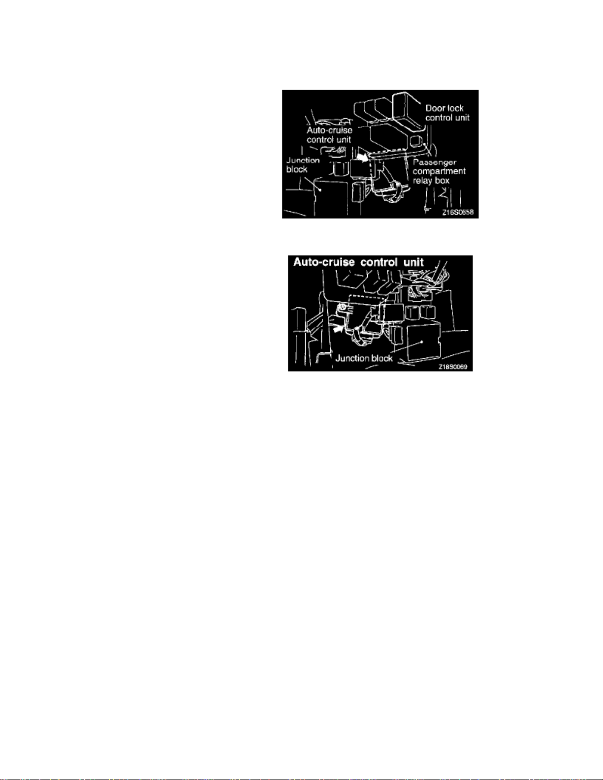
Auto-Cruise And Door Lock Control Unit
Door Lock Control Unit
Page 3

Page 4
> Relays and Modules > Relays and Modules - Body and Frame > Power Door Lock Relay > Component Information > Locations
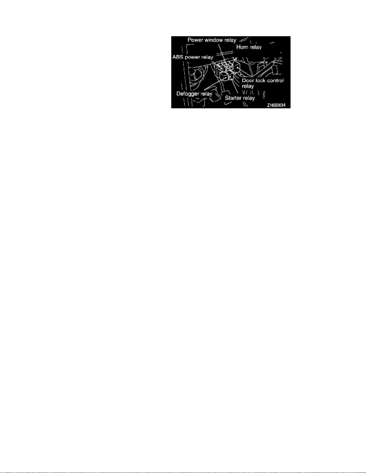
ABS Power, Power Window, Horn, Defogger, Door Lock Control And Starter Relay
Page 5

Page 6

> Relays and Modules > Relays and Modules - Cooling System > Radiator Cooling Fan Motor Relay > Component Information > Locations
Radiator Cooling Fan Motor Relay: Locations
Headlight, Taillight, Radiator Fan Motor And Generator Relay
Radiator Fan Motor Control Or Condenser Fan Motor Relay And Fan Motor Control Relay A/C Compressor Clutch Relay.
Page 7

Page 8

> Relays and Modules > Relays and Modules - Cooling System > Radiator Cooling Fan Motor Relay > Component Information > Locations > Page 14
Radiator Cooling Fan Motor Relay: Testing and Inspection
Fig. 29 Radiator Fan Motor Relay Location
1. Remove relay from engine compartment relay box, .Fig. 29
Page 9

Fig. 30 Radiator Fan Motor Relay Inspection
Fig. 30
2. Check for continuity between terminals with battery (+) and (-) applied intermittently to terminals 1 and 3 respectively, .3. When battery voltage is applied, continuity should exist between terminals 1 and 3 and between terminals 4 and 5; when voltage is removed,
continuity should exist only between terminals 1 and 3.
4. If results are as indicated, relay is satisfactory; if not, a new relay should be installed.
Page 10
> Relays and Modules > Relays and Modules - Cruise Control > Cruise Control Module > Component Information > Locations
Cruise Control Module: Locations
Auto-Cruise And Door Lock Control Unit
Auto Cruise Control Unit
Page 11

Page 12

> Relays and Modules > Relays and Modules - HVAC > Blower Motor Relay > Component Information > Locations
Blower Motor Relay And Turn-Signal And Hazard Flasher Unit
Page 13

Page 14

> Relays and Modules > Relays and Modules - HVAC > Compressor Clutch Relay > Component Information > Locations
Page 15

Page 16

> Relays and Modules > Relays and Modules - HVAC > Compressor Clutch Relay > Component Information > Diagrams > Diagram Information and Instructions
Compressor Clutch Relay: Diagram Information and Instructions
Connector and Ground Indicators
Page 17

> Relays and Modules > Relays and Modules - HVAC > Compressor Clutch Relay > Component Information > Diagrams > Diagram Information and Instructions > Page 28
Mirage L4-1468cc 1.5L SOHC 12 Valve (1996)
Connector/Ground Indications
Connector/Grounding Indications
Page 18
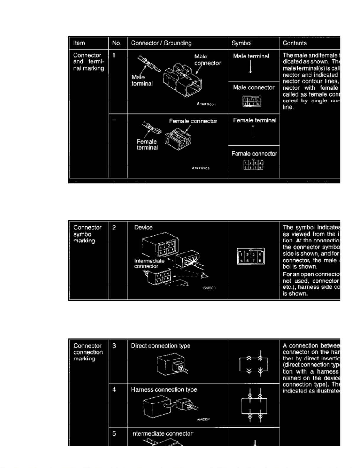
Connector And Terminal Marking
Connector And Terminal Marking
Connector Symbol Marking
Connector Symbol Marking
Page 19

> Relays and Modules > Relays and Modules - HVAC > Compressor Clutch Relay > Component Information > Diagrams > Diagram Information and Instructions > Page 29
Mirage L4-1468cc 1.5L SOHC 12 Valve (1996)
Connector Connection Marking
Connector Connection Marking
Page 20

Grounding Markings
Grounding Markings
How to Read Circuit Diagrams
Page 21

> Relays and Modules > Relays and Modules - HVAC > Compressor Clutch Relay > Component Information > Diagrams > Diagram Information and Instructions > Page 30
Mirage L4-1468cc 1.5L SOHC 12 Valve (1996)
Page 22

How To Read Circuit Diagrams (Part 1 Of 2)
Page 23

> Relays and Modules > Relays and Modules - HVAC > Compressor Clutch Relay > Component Information > Diagrams > Diagram Information and Instructions > Page 31
Mirage L4-1468cc 1.5L SOHC 12 Valve (1996)
Page 24

How To Read Circuit Diagrams (Part 2 Of 2)
Page 25

> Relays and Modules > Relays and Modules - HVAC > Compressor Clutch Relay > Component Information > Diagrams > Diagram Information and Instructions > Page 32
Mirage L4-1468cc 1.5L SOHC 12 Valve (1996)
The circuit of each system from the fuse (or fusible link) to ground is shown. The power supply is shown at the top and the ground at the bottom tofacilitate understanding of how the current flows.
Page 26

How To Read Configuration Diagrams
Page 27

> Relays and Modules > Relays and Modules - HVAC > Compressor Clutch Relay > Component Information > Diagrams > Diagram Information and Instructions > Page 33
Mirage L4-1468cc 1.5L SOHC 12 Valve (1996)
Wire Color Codes
Page 28

Wire Color Codes
If a cable has two colors, the first of the two color code characters indicates the basic color (color of the cable coating) and the second indicates themarking color.
Examples Of Wire Color Codes
Example of Wire Color Code
Page 29

Page 30

> Relays and Modules > Relays and Modules - HVAC > Compressor Clutch Relay > Component Information > Diagrams > Diagram Information and Instructions > Page 34
Page 31

Page 32

> Relays and Modules > Relays and Modules - HVAC > Compressor Clutch Relay > Component Information > Testing and Inspection > Related Diagnostic Procedures
Page 33

Page 34

> Relays and Modules > Relays and Modules - HVAC > Compressor Clutch Relay > Component Information > Testing and Inspection > Related Diagnostic Procedures > Page 37
Compressor Clutch Relay: Testing and InspectionTroubleshooting Hints
If the air compressor magnet clutch is not activated when the air conditioning switch is turned ON during idling, faulty air conditioning control system issuspected.
Page 35

Page 36

> Relays and Modules > Relays and Modules - HVAC > Compressor Clutch Relay > Component Information > Testing and Inspection > Related Diagnostic Procedures > Page 38
Page 37

Page 38

> Relays and Modules > Relays and Modules - HVAC > Condenser Fan Motor Relay, HVAC > Component Information > Locations
Radiator Fan Motor Control Or Condenser Fan Motor Relay And Fan Motor Control Relay A/C Compressor Clutch Relay.
Page 39

Page 40

> Relays and Modules > Relays and Modules - HVAC > Control Module HVAC > Component Information > Locations
Automatic Compressor Control Unit
Page 41

Page 42

> Relays and Modules > Relays and Modules - HVAC > Control Module HVAC > Component Information > Locations > Page 45
Auto Compressor Control Unit HI Signal Output Conditions
Page 43

Page 44

> Relays and Modules > Relays and Modules - HVAC > Control Module HVAC > Component Information > Locations > Page 46
Control Module HVAC: Testing and Inspection
See Cooling Circuit
Page 45

Page 46
> Relays and Modules > Relays and Modules - HVAC > Control Module HVAC > Component Information > Locations > Page 47
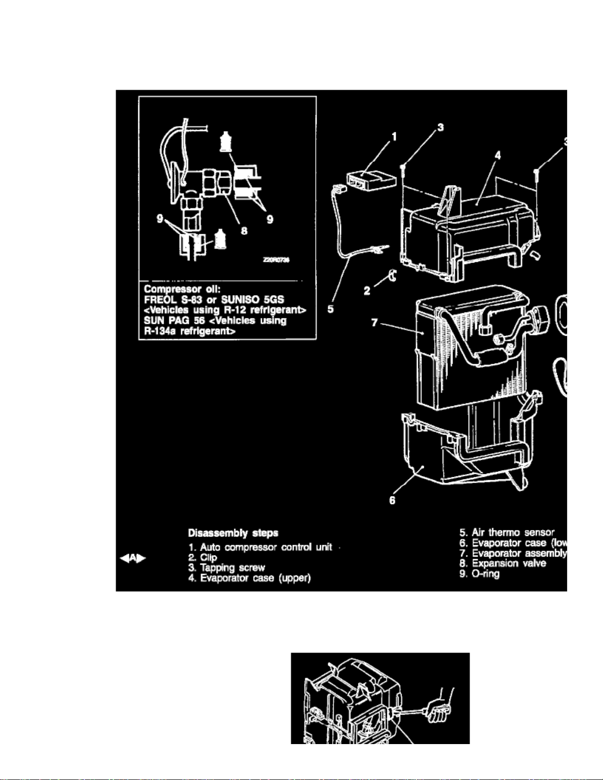
Control Module HVAC: Service and Repair
DISASSEMBLY AND REASSEMBLY
DISASSEMBLY SERVICE POINT
Page 47

CLIPS REMOVAL
Remove the slips with a flat-blade screwdriver covered with a shop towel to prevent damage to case surfaces.
Page 48

> Relays and Modules > Relays and Modules - Lighting and Horns > Headlamp Relay > Component Information > Locations
Headlight, Taillight, Radiator Fan Motor And Generator Relay
Page 49

Page 50

> Relays and Modules > Relays and Modules - Lighting and Horns > Headlamp Relay > Component Information > Locations > Page 52
Conditions For Switch - ON Of Headlight Relay
Page 51

Page 52

> Relays and Modules > Relays and Modules - Lighting and Horns > Headlamp Relay > Component Information > Locations > Page 53
Headlamp Relay: Testing and Inspection
Headlight Relay Continuity Check
Headlight Relay Continuity Check Table
1. Take out the headlight relay from the engine compartment relay box.2. Connect battery to terminal 1 and check continuity between terminals with terminal 3 grounded.
Page 53

Page 54

> Relays and Modules > Relays and Modules - Lighting and Horns > Horn Relay > Component Information > Locations
ABS Valve, ABS Motor And Horn Relay
Page 55

Page 56

> Relays and Modules > Relays and Modules - Lighting and Horns > Horn Relay > Component Information > Locations > Page 57
Horn Relay: Testing and Inspection
Horn Relay Continuity Check
1. Remove the horn relay.
Horn Relay Continuity Check Table
2. Check for continuity between the terminals.
Page 57

Page 58

> Relays and Modules > Relays and Modules - Lighting and Horns > Tail Lamp Relay > Component Information > Locations
Headlight, Taillight, Radiator Fan Motor And Generator Relay
Page 59

Page 60

> Relays and Modules > Relays and Modules - Power and Ground Distribution > Relay Box > Component Information > Locations
Relay Box: Locations
Main relay centers are located behind left-hand side of instrument panel and on right-hand side of engine compartment.
Page 61

Page 62

> Relays and Modules > Relays and Modules - Power and Ground Distribution > Relay Box > Component Information > Diagrams > Diagram Information and Instructions
Relay Box: Diagram Information and Instructions
Connector and Ground Indicators
Page 63

> Relays and Modules > Relays and Modules - Power and Ground Distribution > Relay Box > Component Information > Diagrams > Diagram Information and Instructions >
Page 67
Mirage L4-1468cc 1.5L SOHC 12 Valve (1996)
Connector/Ground Indications
Connector/Grounding Indications
Page 64

Connector And Terminal Marking
Connector And Terminal Marking
Connector Symbol Marking
Connector Symbol Marking
Page 65

> Relays and Modules > Relays and Modules - Power and Ground Distribution > Relay Box > Component Information > Diagrams > Diagram Information and Instructions >
Page 68
Mirage L4-1468cc 1.5L SOHC 12 Valve (1996)
Connector Connection Marking
Connector Connection Marking
Page 66

Grounding Markings
Grounding Markings
How to Read Circuit Diagrams
Page 67

> Relays and Modules > Relays and Modules - Power and Ground Distribution > Relay Box > Component Information > Diagrams > Diagram Information and Instructions >
Page 69
Mirage L4-1468cc 1.5L SOHC 12 Valve (1996)
Page 68

How To Read Circuit Diagrams (Part 1 Of 2)
Page 69

> Relays and Modules > Relays and Modules - Power and Ground Distribution > Relay Box > Component Information > Diagrams > Diagram Information and Instructions >
Page 70
Mirage L4-1468cc 1.5L SOHC 12 Valve (1996)
Page 70

How To Read Circuit Diagrams (Part 2 Of 2)
Page 71

> Relays and Modules > Relays and Modules - Power and Ground Distribution > Relay Box > Component Information > Diagrams > Diagram Information and Instructions >
Page 71
Mirage L4-1468cc 1.5L SOHC 12 Valve (1996)
The circuit of each system from the fuse (or fusible link) to ground is shown. The power supply is shown at the top and the ground at the bottom tofacilitate understanding of how the current flows.
Page 72

How To Read Configuration Diagrams
Page 73

> Relays and Modules > Relays and Modules - Power and Ground Distribution > Relay Box > Component Information > Diagrams > Diagram Information and Instructions >
Page 72
Mirage L4-1468cc 1.5L SOHC 12 Valve (1996)
Wire Color Codes
Page 74

Wire Color Codes
If a cable has two colors, the first of the two color code characters indicates the basic color (color of the cable coating) and the second indicates themarking color.
Examples Of Wire Color Codes
Example of Wire Color Code
Page 75

Page 76

> Relays and Modules > Relays and Modules - Power and Ground Distribution > Relay Box > Component Information > Diagrams > Diagram Information and Instructions > Page 73
Junction Block
Page 77

Page 78

> Relays and Modules > Relays and Modules - Power and Ground Distribution > Relay Box > Component Information > Diagrams > Page 74
Relay Box: Application and ID
Dedicated Fuse 6, 7 (A/C Compressor Clutch Relay Bracket In Engine Compartment)
Multi-Purpose Fuse (Relay Box In Engine Compartment)
Page 79

> Relays and Modules > Relays and Modules - Power and Ground Distribution > Relay Box > Component Information > Diagrams > Page 75
Mirage L4-1468cc 1.5L SOHC 12 Valve (1996)
Page 80

Multi-Purpose Fuse (A/C Compressor Clutch Relay Bracket In Engine Compartment)
Multi-Purpose Fuse (Relay Box In Passenger Compartment)
Page 81

Page 82

> Relays and Modules > Relays and Modules - Powertrain Management > Relays and Modules - Computers and Control Systems > Engine Control Module > Component Information > Technical Service Bulletins > All
Technical Service Bulletins for Engine Control Module: > 03-00-015 > Sep > 03 > Engine Controls - PCM Reprogramming Procedure
Technical Service Bulletin # 03-00-015
Engine Controls - PCM Reprogramming Procedure
No: TSB-03-00-015 DATE: September, 2003MODEL: All models
SUBJECT:REPROGRAMMING WITH THE MUT-III
PURPOSE
This bulletin contains general instructions for reprogramming a vehicle PCM using the MUT-Ill vehicle communication interface (VCI) unit. Beforebeginning reprogramming, you must first transfer the reprogramming data to a PC memory card adapter equipped with a compact flash memory chip.New data is transferred from a DVD to the PC hard drive, then to the PC memory card. After data is in the memory card, it can be downloaded to theVCI, then to the vehicle's PCM (ECU).
The MUT-III is capable of both automatic reprogramming (it automatically selects the appropriate database) and manual reprogramming (you select thedatabase). Automatic reprogramming is recommended for most typical reprogramming situations. If automatic reprogramming is not successful, trymanual reprogramming.
AFFECTED VEHICLES
Page 83

> Relays and Modules > Relays and Modules - Powertrain Management > Relays and Modules - Computers and Control Systems > Engine Control Module > Component
Information > Technical Service Bulletins > All Technical Service Bulletins for Engine Control Module: > 03-00-015 > Sep > 03 > Engine Controls - PCM Reprogramming
Procedure > Page 86
Mirage L4-1468cc 1.5L SOHC 12 Valve (1996)
All models capable of PCM reprogramming, except 1995-99 Eclipse 2.0L non-turbo (For 1995-99 Eclipse 2.0L non-turbo models, use M1T992000-Aand refer to the applicable TSB.)
I. Transferring Reprogramming Data to Memory Card
Page 84

Before beginning reprogramming, you must first transfer new reprogramming data from a DVD to a PC memory card adapter equipped with a compactflash memory chip. The data is transferred from the DVD-ROM to the PC hard drive, then to the PC memory card.
Components
MUT-III personal computerReprogramming database on DVD-ROMMemory card (MB991853)128 MByte Compact Flash (CF) *Memory card adapter (MB991939) PCMCIA *
* Replacement generic memory and adapters can be ordered from SPX/OTC, or purchased locally.
Procedure
1. Start the MUT-III personal computer.
2. Start the MUT-III system.
3. Install the memory card into the card adaptor.
4. Install the card adapter into the PC card slot. (There are two PC card slots. You can use either slot for the card adapter.)
A "Found New Hardware" message displays on the monitor. Wait for the message to disappear.
Page 85

> Relays and Modules > Relays and Modules - Powertrain Management > Relays and Modules - Computers and Control Systems > Engine Control Module > Component
Information > Technical Service Bulletins > All Technical Service Bulletins for Engine Control Module: > 03-00-015 > Sep > 03 > Engine Controls - PCM Reprogramming
Procedure > Page 87
Mirage L4-1468cc 1.5L SOHC 12 Valve (1996)
5. When you receive new reprogramming data, install the reprogramming DVD-ROM into the PC's DVD-ROM drive.
6. Select "Special function".
7. Select "ECU reprogramming".
8. If a "Please update to a new database file" message displays, press the check mark button.
9. A "Please wait!" message displays. When the transfer is complete, the message disappears. Then remove the DVD-ROM from the PC.
10. Select "Memory card transfer". (Do not remove the memory card from the PC.)
11. Select memory card "E:\" and press the check mark button.
Page 86

12. When the message "It transfers data to the memory card. Are you ready?" displays, press the check mark button.
13. A progress monitor displays during data transfer to the memory card.
14. When the message "Transfer is complete" appears, press the check mark button.
To remove the memory card:
15. Double-click the removal icon in the lower right corner of the screen.
16. Select "PCMCIA IDE/ATAPI Controller" . Then press the Stop button.
17. Verify that the correct item is selected, then press the OK button.
When the message "The device can now be safely removed from the system" displays, remove the memory card (press the button next to the PCcard slot).
II. Reprogramming A Vehicle ECU With the Vci
NOTE
After data is in the memory card, it can be downloaded to the VCI, then to the vehicles PCM (ECU). : Whenever the ECU is reprogrammed, areprogramming label (p/n MSSF-024G-00) must be completed and affixed to the vehicle. Refer to the applicable reprogramming TSB for specificinformation that must be entered on the label.
VCI COMPONENTS
Page 87

> Relays and Modules > Relays and Modules - Powertrain Management > Relays and Modules - Computers and Control Systems > Engine Control Module > Component
Information > Technical Service Bulletins > All Technical Service Bulletins for Engine Control Module: > 03-00-015 > Sep > 03 > Engine Controls - PCM Reprogramming
Procedure > Page 88
Mirage L4-1468cc 1.5L SOHC 12 Valve (1996)
Page 88

These components are required:
Page 89

> Relays and Modules > Relays and Modules - Powertrain Management > Relays and Modules - Computers and Control Systems > Engine Control Module > Component
Information > Technical Service Bulletins > All Technical Service Bulletins for Engine Control Module: > 03-00-015 > Sep > 03 > Engine Controls - PCM Reprogramming
Procedure > Page 89
Mirage L4-1468cc 1.5L SOHC 12 Valve (1996)
CONNECTING COMPONENTS
1. Insert the memory card into the PC card adapter. Then install into the VCI main unit.
2. Connect the MUT-III main harness A or B to the VCI main unit.
3. With the ignition switch in the OFF position, connect the MUT-III main harness to the data link connector.
:NOTE
Page 90

For Outlander and 2002-on Montero models, use 12-pin to 13-pin adapter harness MB991855 to connect the main harness to the data linkconnector.
4. Turn the ignition switch to the ON position.
MAIN MENU
Turn the ignition key to ON. When the VCI unit is turned on, the main menu displays:
IMPORTANT
^ When connecting and disconnecting, do not pull on the harness wires. Pull only on the connectors.
^ During reprogramming, the ignition switch must remain ON.
^ Do not disturb the MUT-III main harness during reprogramming. After reprogramming, start the engine to verify operation.
Automatic reprogramming is recommended for most typical reprogramming situations. If automatic reprogramming is not successful, try manualreprogramming.
AUTOMATIC REPROGRAMMING
1. In the VCI main menu. select "Automatic RPG". Then press ENTER.
The available data will display.
2.
Press ENTER. If the PCM requires reprogramming, the MUT-Ill will automatically identify the appropriate database. Press ENTER again totransfer the reprogramming data to the VCI.
a. If the PCM does NOT require reprogramming, this message displays. Press ENTER to return to the main menu.
Page 91

> Relays and Modules > Relays and Modules - Powertrain Management > Relays and Modules - Computers and Control Systems > Engine Control Module > Component
Information > Technical Service Bulletins > All Technical Service Bulletins for Engine Control Module: > 03-00-015 > Sep > 03 > Engine Controls - PCM Reprogramming
Procedure > Page 90
Mirage L4-1468cc 1.5L SOHC 12 Valve (1996)
b. If there is no data for reprogramming this PCM, this message displays and no data is transferred. Press ENTER to return to the main menu.
Page 92

3. A progress monitor displays during data transfer to the VCI internal memory.
4. When data transfer is complete, ECU reprogramming automatically begins.
5. The ECU part number and ROM ID are displayed. Press ENTER to continue with reprogramming.
Page 93

> Relays and Modules > Relays and Modules - Powertrain Management > Relays and Modules - Computers and Control Systems > Engine Control Module > Component
Information > Technical Service Bulletins > All Technical Service Bulletins for Engine Control Module: > 03-00-015 > Sep > 03 > Engine Controls - PCM Reprogramming
Procedure > Page 91
Mirage L4-1468cc 1.5L SOHC 12 Valve (1996)
6.
If the database you selected does not apply to the vehicle's PCM, this message will display. Press ENTER to return to the VCI main menu.Confirm PCM part number and appropriate reprogramming database number.
Page 94

7.
If the PCM has already been reprogrammed with this database, or if the MUT-III main harness is not properly connected to the VCI unit, thismessage displays and reprogramming will not continue.
8. Verify that the harness is connected properly, then press ENTER. The VCI will retry reprogramming.
Page 95

> Relays and Modules > Relays and Modules - Powertrain Management > Relays and Modules - Computers and Control Systems > Engine Control Module > Component
Information > Technical Service Bulletins > All Technical Service Bulletins for Engine Control Module: > 03-00-015 > Sep > 03 > Engine Controls - PCM Reprogramming
Procedure > Page 92
Mirage L4-1468cc 1.5L SOHC 12 Valve (1996)
9. A monitor indicates that reprogramming is in progress.
There are five phases in the reprogramming process. The VCI will continue with the process automatically. Do not press any key.
Step 1: Saves data to the back-up memory.
Page 96

Step 2: Erases data in the ECU.
Step 3: Writes new data in the ECU.
Step 4: Verifies the new data is transferred.
Step 5: Erases diagnosis and back-up memory.
10. The new ECU part number and ROM-ID display.
You must turn the ignition switch to OFF to complete the reprogramming process.
11. Start the engine and disconnect the MUT-III.
MANUAL REPROGRAMMING
1. In the main menu, select "Load RPG file". Then press ENTER.
Page 97

> Relays and Modules > Relays and Modules - Powertrain Management > Relays and Modules - Computers and Control Systems > Engine Control Module > Component
Information > Technical Service Bulletins > All Technical Service Bulletins for Engine Control Module: > 03-00-015 > Sep > 03 > Engine Controls - PCM Reprogramming
Procedure > Page 93
Mirage L4-1468cc 1.5L SOHC 12 Valve (1996)
2. Select the reprogramming database by using the down arrow. Then press ENTER.
Page 98

3. If the correct database is selected, press ENTER. If not, press ESC to cancel and return to the main menu.
4. A progress monitor displays during data transfer to the PC memory card.
5. After the data has been transferred to the PC memory card, this message displays.
6. The ECU part number and ROM ID are displayed. Press ENTER to continue with reprogramming.
Page 99

> Relays and Modules > Relays and Modules - Powertrain Management > Relays and Modules - Computers and Control Systems > Engine Control Module > Component
Information > Technical Service Bulletins > All Technical Service Bulletins for Engine Control Module: > 03-00-015 > Sep > 03 > Engine Controls - PCM Reprogramming
Procedure > Page 94
Mirage L4-1468cc 1.5L SOHC 12 Valve (1996)
Page 100

7. If the database you selected does not apply to the vehicle's PCM, this message will display.
Press ENTER to return to the VCI main menu. Confirm PCM part number and appropriate reprogramming database number.
8. If the PCM has already been reprogrammed with this database, this message displays and reprogramming will not continue.
It is possible that the MUT-III main harness is not properly connected to the VCI unit.
 Loading...