

Page 1

BACKUP
Service Manual
ENGINE
1992
-
1993
FOREWORD
The information contained in this service manual
has been prepared for the professional automotive
technician involved in daily repair operations. Information in this manual is divided into groups by
engine models. Each group is further divided to
address individual components within the group.
These groups contain general information, specification, removal and installation, disassembly and
reassembly procedures for the components. The
first page of each group contains an alphabetical
index to assist in finding the location of the
component. The information, descriptions and specifications were in effect at the time this manual
was released.
GROUP INDEX
Introduction
Engine
4Gl
463
466 <1992>
. . . . . . . . . . . . . . . . . . . . . . . . . . . . . . . . . . . . . . . .
. . . . . . . . . . . . . . . , . . . . . . . . . . . . . . . . . . . . . . . .
. . . . . . . . . . . . . . . . . . . . . . . . . . . .
mm
. . . . . . . . . . . . . . . . . . . . . . . .
mm
This
BACKUP DSM manual IS to be used ONLY as a BACKUP. Please DO NOT REDISTRIBUTE
WHOLE SECTIONS.
a GENUINE DSM MANUAL. It CANNOT BE considered a REPLACEMENT (Unless your original
manual was lost or destroyed.)
Please See
Mitsubishi Motors Co[poration reserves the right to make changes
dew?
or to make addltlons to or improvements in its products
impoang
previously manufactured.
This
BACKUP was sold to you under the fact that you do
README.N
any obligations upon itself to install them on its products
or
READMEHTML
Thank you. G~mm~emymanual@hotma~l.com
VOLUNTARY TECHNICIAN
CERTIFICATION THROUGH
for
additional Information.
WE SUPPORT
National
lnstit~te
AUTOMOTIVE
SERVICE
EXCELLENCE
for
indeed
OWN
WIthout
469
6G7
4G6 <1993>
in
. . . . . . . . . . . . . . . . . . . . . . . . . . . . . . . . . . ...*..
m
. . . . . . . . . . . . . . . . . . . . . . . . . . . . . . . . . . . . . . . .
. . . . . . . . . . . . . . . . . . . . . . . .
CCT
@ qgg2
M&ubi&i Motors Corporation
Printed in Japan
Page 2

Page 3

INTRODUCTION
CONTENTS
:,
ENGINE MODEL TABLE
EXPLANATION OF MANUAL CONTENTS
FORM-IN-PLACE GASKET
Disassembly
Form-In-Place Gasket Application
Surface
Preparation
. . . . . . . . . . . . . . . . . . . . . . . . . . . . . . . . . . . . . . . . . . . . . . . . . . . . . . . .
. . . . . . . . . . . . . . . . . . . . . . . . . . . . . . . . . . . . . . . .
. . . . . . . . . . . . . . . . . ..I................
._......................
. . . . . . . . . . . . . . . . . . . . . . . . . . . . . . . . . . . . . . . . . . . .
4
. . . . . . . .
2
6
6
6
6
SPECIAL TOOL NOTE
TORQUE REFERENCES
. . . . . . . . . . . . . . .
. . . . . . . . . . . . . . . . . . . . . . . . . . . . .
. . . . . . . . . . . . . . . . . . . . . . . . . . . . . . . . ..I.....
1.
:
._
.
5
5
,
‘-:
:
Page 4

2
INTRODUCTION
EXPLANATION OF MANUAL CONTENTS
0
Maintenance and Servicing Procedures
(1) A diagram of the component parts is
provided near the front of each section in
order to give the reader a better under-
standing of the installed condition of
component parts.
(2) The numbers provided within the diagram
indicate the sequence for maintenance
and servicing procedures; the symbol
indicates a non-reusable part; the tighten-
ing torque is provided where applicable.
m
Removal steps:
l Disassembly steps:
0
Installation steps:
l Reassembly steps:
I
The part designation number corresponds
to the number in the illustration to indicate
removal steps.
The part designation number corresponds
to the number in the illustration to indicate
disassembly steps.
Specified in case installation is impossible
in reverse order of removal steps. Omitted if installation is possible in reverse
order of removal steps.
Specified in case reassembly is
ble
in reverse order of disassembly
Omitted if reassembly is possible
verse order of disassembly steps.
ia
im$ossi-
Classification of Major Maintenance/
Service Points
When there are major points relative to maintenance and servicing procedures (such as essential
maintenance and service points, maintenance and
service standard values, information regarding the
use of special tools, etc.), these are arranged
together as major maintenance and service points
and explained in detail.
GAO:
Indicates that there are essential points for
removal or disassembly.
I)A4:
Indicates that there are essential points for
installation or reassembly.
Symbols for Lubrication, Sealants and
Adhesives
Information concerning the locations for
tion and for application of sealants and adhesives
is provided, by using symbols, in the diagram of
component parts, or on the page following the
component parts page, and explained.
lubrica-
&
. . Grease
(multrpurpose grease unless there is
a brand or type specified)
. . . . .
Sealant or adhesive
. . . . .
i
:m
Brake fluid, automatic transmission
fllid
or air conditioning compressor
. . . . . Engine oil or gear oil
I
TSB Revision
Page 5

INTRODUCTION
Indicates the
section title.
3
Denotes non-reusable
This number corresponds to the
number appearing in “Removal
steps”, “Disassembly steps”,
stallation steps” or “Reassembly
steps”
Operating procedures, cautions,
etc. on removal, installation, disassembly and reassembly are described.
“ln-
I
I
TSB Revision
Page 6

4
ENGINE MODEL TABLE - 1992
Engine
Series,
4Gl
4G3
4G6
INTRODUCTION
4G9
6G7
4693
6672
6G72 3.0 (183)
6G72
Turbo
1.8
(1
IO)
3.0(I83)
3.0 (183)
ENGINE MODEL TABLE - 1993
In-line,
6O”V.
SOHC
6O”V.
DOHC
6O“V.
DOHC
SOHC
(per bank)
(per bank)
(per bank)
E$po
LRV
bgmante,
h&ntero,
Diamante, 3000GT
4 3000GT
.K
c:
Truck
4G9
6G7
4664
4G93
6672
6672
6G72
Turbo
.
2.4(146)
1.8 (1
IO)
3.0 (I 83)
3.0 (183)
3.0 (183)
1
TSB Revision
In-line, SOHC
In-line, SOHC
6O”V.
SOHC
(per bank)
6O”V,
DOHC 4
(per bank)
6O”V.
DOHC
(per bank)
4
4
2
4
E$po-LRV.
@age,
Diamante,
Mhtero,
C$mante,
3600GT
Expo LRV
Expo
Truck
3000GT
Page 7

SPECIAL TOOL NOTE
INTRODUCTION
.
1
6
Please refer to the special tool cross reference chart which is located in the service manual at the beginning of
each group, for a cross reference from the MMC special tool number to the special tool number that is
available in your market.
iiS *‘l
*.j,
l”
“...!: ‘/’
TORQUE REFERENCES
General tightening torque is as shown in the following table.
The specific part tightening torque is shown at the beginning of each group.
Flange bolt
Heaid.
i-MC 7
ft.lbS.
Size mm
(dia. x pitch)
5 x 0.8
6x
1.0
8 x 1.25
10x1.25
12x
1.25
14x1.5
Bolt with spring washer
Head mark 4 Head mark 7 Head mark 10 Head mark 4
Nm
ft.lbs. Nm ft.lbs. Nm ft.lbs. Nm ft.lbs. Nm
NEW TIGHTENING METHOD - BY USE OF BOLTS TO BE TIGHTENED IN PLASTIC AREA
A new type of bolts, to be tightened in plastic area, is currently used in
tightening method for the bolts is different from the conventional one. Be sure to observe the
so’me
parts of the engine. The
method
described in the text when tightening the bolts.
Service limits are provided for the bolts. Make sure that the service limits described in the text are strictly
observed.
l Areas where the bolts are in use:
(1) Cylinder head bolts
(2)
Main bearing cap bolts
(3) Connecting rod cap bolts
Remarks:
The bolts in
The bolts in (3) apply to the
l Tightening Method
After tightening the bolts to the specified torque, tighten them another
(1)
and (2) apply to the
4G15, 4G6 <1993>
4G6 <I 993>
and
and
4G93
4693
engines.
engines.
90”
or 180” (twice 90”). The
tightening method varies on different areas. Observe the tightening method described in the text.
TSB Revision
Page 8

INTRODUCTION
FORM-IN-PLACE GASKET
The engine has several areas where the form-in-place gasket
serves its purpose, it is necessary to observe some precautions when applying the gasket. Bead size,
continuity and location are of paramount importance. Too thin a bead could cause leaks. Too thick a bead, on
the other hand, could be squeezed out of location, causing blocking or narrowing of the fluid feed line. To
eliminate the possibility of leaks from a joint, therefore, it is absolutely necessary to apply the gasket evenly
without a break, while observing the correct bead size.
The
FIPG
used in the engine is a room temperature vulcanization (Rn/) type and is supplied in a loo-gram
tube (Part No. MD970389 or
atmospheric air, it is normally used in the metallic flange areas. The FIPG, Part No.
for sealing both engine oil and coolant, while Part No. 997110 can only be used for engine oil sealing.
Disassembly
The parts assembled with the
cases, however, the sealant between the joined surfaces may have to be broken
mallet or similar tool. A flat gasket scraper may be lightly hammered in between the joined surfaces. In this
case, however, care must be taken to prevent damage to the joined surfaces.
MD9971 10).
FIPG
can be easily disassembled without use of a special method. In some
Since the
RTV
(FIPG)
is in use. To ensure that the gasket fully
hardens as it reacts with the moisture in the
MD970389,
bylightly
can be used
striking with a
Surface
Thoroughly remove all substances deposited on the gasket application surfaces, using a gasket scraper or
wire brush. Check to ensure that the surfaces to which the
are no oils, greases and foreign substances deposited on the application surfaces. Do:not forget to remove
the old sealant remaining in the bolt holes.
Form-In-Place Gasket Application
When assembling parts with the FIPG, you must observe some precautions, but the procedure is very simple
as in the case of a conventional precut gasket.
Applied
circumference with a completely continuous bead. The
the
make sure that the gasket is applied to the required area only.
The
when applying the FIPG.
Preparation
FIPG
is to be applied is flat.‘ Make sure that there
5
FIPG
bead should be of the specified size and without breaks. Also be sure
FIPG
can be wiped away unless it is hardened. While
FIPG
is still moist (in less than 15 minutes), mount the parts in position. When the parts are mounted,
FIPG
application procedure may vary on different areas. Observe the procedure described in the text
toencircle
the bolt hole
TSB Revision
Page 9

4G15
CONTENTS
BRACKET
CRANKSHAFT, FLYWHEEL AND
DRIVE PLATE
CYLINDER HEAD AND VALVES
EXHAUST MANIFOLD AND
WATER PUMP
FRONT CASE AND OIL PUMP
FUEL AND EMISSION PARTS
GENERAL INFORMATION
GENERAL SPECIFICATIONS
GENERATOR AND IGNITION SYSTEM
................................................................
........................................................
........................
....................................................
............................
............................
................................
............................
........
53
51
33
28
39
22
14
INTAKE
PISTON AND CONNECTING ROD
ROCKER ARMS AND CAMSHAFT
SEALANT
SERVICE SPECIFICATIONS
SPECIAL TOOLS
THROlTLE
TIMING
2
TORQUE SPECIFICATIONS
5
MANIFOLD
................................................................
BODY
BELT
............................................
....................
....................
................................
....................................................
................................................
........................................................
................................
26
43
30
11
6
12
24
17
10
Page 10

IlA-2
4Gl
ENGINE - General Information
GENERAL INFQRMATION
ENGINE SECTIONAL VIEW
TSB Revision
3
1
EN0086
Page 11

4Gl
ENGINE
-
General Information
TSB Revision
1
Page 12

VA-4
4Gl
ENGINE - General Information
UBRICATION
SYSTEM
0’
t7;
ii
I
P
‘Z
:
ii
OTJ
09
1
TSB Revision
Page 13

4Gl
ENGINE - General Specifications
GENERAL SPECIFICATIONS
Items
We
Number of cylinders
Combustion chamber
Total displacement
Cylinder bore
Piston stroke
Compression ratio
Valve timing
(): Camshaft identification mark
Intake valve
Opens
Closes
Exhaust valve
Opens
Closes
Lubrication system
Oil pump type
Cooling system
Water pump type
EGR valve
Injector type and number
Injector identification No.
Fuel regulated pressure kpa (psi)
Throttle bore mm (in.)
Throttle position sensor
Closed throttle position switch
Y’
1: up to 1992 models
“2:
From 1993 models
.---
cm3 (cu.in.)
mm (in.)
mm (in.)
BTDC
ABDC
BBDC
ATDC
Specifications
In-line OHV, SOHC
4
Pentroof
1,468 (89.58)
75.5 (2.972)
82 (3.228)
9.2
(1 I*’
14”
51” 53”
51” 57”
14”
Pressure feed, full-flow filtration
Trochoid type
Water-cooled forced circulation
Centrifugal impeller type
Single type
Electromagnetic, 4
BDH182
335 (47.6)
46(1.811)
dariable
Contact type, within idle speed control
Movable contact type within throttle position sensor*’
type
(6)**
15”
15”
resistor type
motor”
1
TSB Revision
I
Page 14

1
IA-6
4Gl
ENGINE - Service Specifications
SERVICE SPECIFICATIONS
Items
Cylinder head
Flatness of gasket surface
Grinding limit of gasket surface
t
Total resurfacing depth of both cylinder
head and cylinder block
Overall height
Oversize rework dimensions of valve guide hole
(both intake and exhaust)
0.05
(.002)
0.25(.010)
0.50
(.020)
Oversize rework dimensions of intake valve
seat ring hole (primary)
0.3
(.012)
0.6(.024)
Oversize rework dimensions of intake valve
seat ring hole (secondary)
0.3
(.012)
0.6
(.024)
Oversize rework dimensions of exhaust valve
seat ring hole
0.3
(.012)
0.6
(.024)
Camshaft
Cam height
Intake
Exhaust 39.10 (1.5394)
Journal diameter
3il
clearance
Standard value
d.05 (.0020)
106.9-107.1 (4.209-4.217)
12.05-12.07 (.4744-.4752)
12.25-
12.27
12.50-12.52 (.4921 -.4929)
27.42-27.44(1.0795-1.0803)
27.72-27.74(1.0913-1.0922)
32.43-32.45
32.73-32.75
35.43-35.45(1.3949-1.3957)
35.73-35.75(1.4067-1.4075)
38.78 (1.5268)
45.93-45.94(1.8083-1.8087)
0.06-0.10(.0024-.0039)
(.4823-.4831)
(1.2768-1.2776)
(1.2886-1.2894)
“”
Limit
0.2(.008)
"0.2
3
1
“1
'$
1,
I)
1
1:
!
(.008)
38.28
38.60(1.5197)
mm (in.)
(1.5071)
qockerarm
.D.
3ocker
arm-to-shaft clearance
qockerarmshaft
I.D.
3verall
length
Intake
Exhaust
TSB Revision
18.91
-18.93(.7445-.7453)
0.01
-0.04(.0004-.0016)
18.89-18.90(.7437-.7441)
365(14.37)
346(13.62)
0.1
(.004)
Page 15

Items
Valve
Overall length
Intake
Exhaust
Stem diameter
Intake
Exhaust
Face angle
Thickness of valve head (margin)
Intake
Exhaust
Stem-to-guide clearance
Intake
Exhaust
Valve clearance
Intake
Exhaust
4Gl
ENGINE - Service Specifications
Standard value
100.75 (3.9665)
101.05 (3.9783)
6.57 - 6.58
6.53 - 6.55
(2587 - .2591)
(2571 - .2579)
45” - 45”30’
1 .o
(.039)
1.5
l.059)
0.02 - 0.05
0.05 - 0.09
0.07
0.09
(0008 - .0020)
(.0020 - .0035)
(.0028)
Up to 1992 models
(.0035)
From 1993 models
0.17 (0067)
Limit
0.5
(020)
1 .o (.039)
0.10
(.0039)
0.15
(.OOSS)
mm (in.)
.,_ ..“.. ..“_
.
.
1 t..
,-i
,
-7, ,i ,,- <
i
7/
Valve spring
Free height
Intake
Exhaust
-oad/installed
height
Intake
Exhaust
3ut-of-squareness
halve
guide
3verall
length
Intake
Exhaust
.D.
I.D.
;ervice size
‘Tess-in
lalve
;eat
lalve
temperature
seat
angle
contact width
Gnkage
iervice size
N/mm
(Ibs./in.)
46.1 (1.815)
46.8 (1.843)
230/40
(51/I
.57)
290140
(64/l
.57)
Max. 2”
44 ( 1.732)
49.5 (1.949)
6.60 - 6.62
12.055 - 12.065
0.05
(.002),
(.2598 - .2606)
(4746 - .4750)
0.25
(.Ol).
Room temperature
43”30’ - 44”
0.9 - 1.3
0.3
LO1 2),
(035 - .051)
0.6
(024)
0.50 (02) oversize
oversize
45.1 (1.776)
45.8 (1.803)
4”
0.2
(.008)
. .
\-TSR
Revision
I
Page 16

IIA-8
4Gl
ENGINE - Service Specifications
mm (in.)
Items
Piston
O.D.
Piston-to-cylinder clearance
Service size
Piston ring
End gap
No. 1 ring
No. 2 ring
Oil ring
Ring-to-ring groove clearance
No. 1 ring
No. 2 ring
Service size
Piston pin
O.D.
Press-in load N (psi)
Press-in temperature
Standard value
75.48 - 75.50 (2.9716 - 2.9724)
0.02 - 0.04
0.25
oversize
0.20 - 0.40 l.0079 -
0.20 - 0.35
0.20 - 0.70
0.03 - 0.07
0.02 - 0.06 f.0008 -
0.25
(.Ol),
oversize
18.003 -
5,000 - 15,000 (1 ,102 - 3,307)
Room temperature
(0008 - .0016)
t.01).
0.50
(.02),
(.0079 - .0138)
LOO79 - .0276)
(.0012 - .0028)
0.50
(.02),
18.005 l.7088 -
0.75
.0157)
.0024)
0.75
(.03),
(.03),
.7089)
1
1
.OO
.OO
(.04)
(04)
Limit
0.8
(.031)
0.8
f.031)
1 .o i.039)
0.1
(.004)
0.1 i.004)
Connecting rod
Big end center-to small end center length
Bend
Twist
Big end side clearance
Crankshaft
End play
Journal O.D.
Pin O.D.
Dut-of-roundness and taper of journal and pin
3il
clearance of journal
3il
clearance of pin
Cylinder
Ilatness
Grinding
3verall
block
.D.
of gasket surface
limit of gasket surface
Total resurfacing depth of both cylinder
block and cylinder head
height
130.95-
0.05
0.1
0.10 - 0.25
0.05-0.18 (.0020- .0071)
48 (1.89)
42 (1.65)
0.005 (.0002)
0.02 - 0.05
0.02 - 0.05
75.50 - 75.53 (2.9724 - 2.9736)
0.05 i.002)
255.9 - 256.1
131.05 (5.1555-5.1594)
(.0020)
(.004)
(.0039 - .0098)
(.0008 - .0020)
(.0008 - .0020)
(10.075 - 10.083)
0.4
f.016)
0.3
(.012)
0.1 i.004)
0.1
(.004)
0.1 i.004)
*0.2
(.008)
TSB
Revision
Page 17

Items
Oil
pump
Tip clearance
Side clearance
Body clearance
Drive belt deflection
New belt
Used belt
Injector
Coil resistance
Throttle position sensor
Resistance
Idle speed control motor
Coil resistance
Idle air control motor
Coil resistance
fI?
kR
rc1
0
4Gl
ENGINE - Service Specifications
Standard value
0.03 - 0.08
0.04-0.10(.0016-.0039)
O.lO-0.18(.0039-.0071)
5.5 -7.0
8.0
(.32)
13 - 16
3.5-6.5
5 - 35 at
28 - 33 at
LOOI
(.22 - .28)
at
20°C (68°F)
20°C (68°F)
20°C (68°F)
2 -
.0031)
Limit
0.35
rn:fq,
(in,
i ,I :, i /
.’
(.Orl38)
Idle speed control motor position sensor
Resistance
kfi
4-6
1
TSB Revision
Page 18

1
IA-IO
4Gl
ENGINE - Torque Specifications
TORQUE SPECIFICATIONS
Generator and ignition system
Oil level gauge guide mounting bolt
Water pulley bolt
pump
Generator brace bolt
Generator brace mounting bolt
Generator pivot nut
Crankshaft bolt
Crankshaft pulley bolt
Spark plug
Distributor
Timing belt
Engine support bracket, left
Tensioner bolt
Camshaft sprocket bolt
Fuel and emission parts
Throttle body mounting bolts
Fuel rail mounting bolts
Fuel regulator bolts
pressure
EGR valve (California) mounting bolts
Nm
11
9
14
24
23
85
14
25
12
36
24
70
19
12
9
13
ftlbs.
-
8
7
10
17
17
61
10
18
9
i
ii 26
17
51
14
‘7
9
7
9
Throttle body
Throttle position sensor attaching bolts
Intake manifold
Cable bracket bolt
Engine coolant temperature gauge unit
Engine coolant temperature sensor
Therm0
flater
Thermostat housing bolt and nut
Intake manifold stay bolt
Engine support bracket stay
Intake manifold bolt and nut
Exhaust manifold and water pump
Exhaust manifold cover “A” bolt
Exhaust manifold cover “A” and
Exhaust manifold cover “B” bolt
Exhaust manifold nut
Vater inlet pipe bolt
Vater
Ixygen
switch
outlet fitting bolt
bolt
pump
sensor
“B”
mounting bolt
2.0
14
11
30
8
19
18
22
36
18
30
9
24
18
14
14
45
1.5
11
8
22
6
14
13
16
26
13
22
7
18
13
11
11
33
jocker
arms and camshaft
jocker cover bolt
locker arm shaft bolt
iocker arm lock nut
TSB Revision
1.8
32
15
1.3
24
11
Page 19

461
ENGINE - Torque Specifications / Sealant
Cylinder head and valves
Cylinder head bolt
Front case and oil pump
pan
Oil drain plug
pan
Oil bolt
Oil screen bolt
Oil relief valve plug
Front case bolt
Oil pump cover screw
Piston and connecting rod
Connecting rod cap nut
Crankshaft, flywheel and drive plate
Flywheel and drive plate
Rear plate bolt
Bell housing cover bolt
Oil seal case bolt
Bearing cap bolt
3il switch
pressure
Nm
73
40
7
19
45
I4
IO
20 +
135
11
9
11
53
19
I/4
turns
ft.lbs.‘, I. ‘-,.‘.,;
53
29
5
14
33
11
8
14.5 +
98
8
7
8
38
14
l/4
turns
$8;
_.”.c
Bracket
Exhaust pipe support bracket
Engine support bracket, front
7011
stopper bracket, front
3011
stopper bracket, rear
SEALANT
Items
Therm0
Engine coolant temperature sensor
Engine coolant temperature gauge unit
Oil pan
Oil pressure switch threads
switch
36
60
65
120
Specified sealant
3M
Nut Locking part No. 4171 or equivalent
3M
Nut Locking part No. 4171 or equivalent
3M
ATD Part No. 8660 or equivalent
Mitsubishi Genuine Part No. MD970389 or equivalent
3M ATD Part No. 8660 or equivalent
26
43
47
87
Quantity
As required
As required
As required
As required
As required
TSB Revision
Page 20

1
IA-12
SPECIAL TOOLS
Tool
4Gl
ENGINE - Special Tools
MD99801 1
Crankshaft rear
oil seal installer
Crankshaft front
oil seal installer
MD99871
Camshaft oil seal
3
MD99801 I-01
MD998713-01
Installation of crankshaft rear oil seal
Installation of camshaft oil seal
TSB Revision
Removal of oil pan
ompresslon 0
,.
i
.
.
Page 21

4Gl
ENGINE - Special Tools
Valve stem seal
compressor
Flywheel stopper
1
TSB Revision
Page 22

4Gl
1 IA-14
ENGINE - Generator and Ignition System
GENERATOR AND IGNITION SYSTEM
REMOVAL AND INSTALLATION
*
_,
12 Nm
9
ftJp3.
14 Nm
10 ft.lbs.
Ji
I
24Nr;l
17
ft.lbs.
9Nm
7
23 Nm
” Rm/b=-
I
n
\!
I
85 Nm
81
ft.lbs.
1
TSB Revision
1
Removal steps
1,
Oil level gauge
2. Oil level gauge guide
3. O-ring
+C4
4. Drive belt
5. Water pump pulley
6. Generator brace
7. Generator
(IA!) +B4
8. Crankshaft bolt
9. Special washer
IO. Crankshaft pulley
11. Damper pulley
12. Spark plug cable
13.
Spark
*A4 ‘ll.
;.s;;$butor
.
-
plug
1
EN0325
Page 23

461
ENGINE
-
Generator and Ignition System
REMOVAL SERVICE POINT
OAo
CRANKSHAFT BOLT REMOVAL
(I) Using the special tool, hold the drive plate or flywheel.
(2) Remove the crankshaft bolt.
INSTALLATION SERVICE POINTS
r)A4
DISTRIBUTOR ASSEMBLY INSTALLATlOy
(1) Turn the crankshaft to bring the No. I cylinder piston to the
top dead center on compression stroke.
(2) Align the mating mark on
thedistributor
housing with that
on the coupling key.
/
1
EL004
(3) Install the distributor with the coupling key fitted in the
keyway at the end of the camshaft.
r)64
CRANKSHAFT BOLT INSTALLATION
(I) Using the special tool, hold the drive plate or flywheel.
(2) Install the crankshaft bolt.
1 EN0326
F
#c4
(I) Adjust the belt deflection with the adjusting bolt to the
1
EN029'
1
TSB Revision
DRIVE BELT TENSION ADJUSTMENT
standard value.
Standard value:
New belt
Used belt
5.5 - 7.0 mm
8.0 mm
(.32
in.)
(.22 - .28
in.)
Page 24

4Gl
ENGINE - Generator and Ignition System
6EN059E
(2)
Or using a tension gauge, adjust the tension to the standard
value.
Standard value:
New belt 500
Used belt 400 N (88 Ibs.)
(3) Tighten the lock bolt to the specified torque.
(4) Tighten the nut for pivot bolt to th$ specified torque.
6EN0591
-
700
N (116 -
154
Ibs.)
1
TSB Revision
I
I
Page 25

461
TIMING BELT
REMOVAL AND INSTALLATION
ENGINE - Timing Belt
2bnhll
17
ft.lbs.
d
7
8
I
Removal steps
1. Timing belt upper cover
2. Timing belt lower cover
@I$ eC4
OBO
$I$
3. Timing belt
4. Engine support bracket, left
5. Tensioner spring
+B4
6. Tensioner
7. Crankshaft sprocket
8. Flange
*A4
9. Camshaft sprocket bolt
10. Camshaft sprocket
TSB Revision
1
EN0327
I
Page 26

461
ENGINE
-
Timing Belt
REMOVAL SERVICE POINTS
OAo
TIMING BELT REMOVAL
(1) Mark belt running direction for reference in reinstallation.
(2) Loosen the tensioner bolts and move the tensioner toward
the water pump.
(3) Remove the timing belt.
NOTE
(1)
Water or oil on the belt shortens its life drastically, so
the removed timing belt, sprocket, and tensioner must
be kept free from oil and water. Do not immerse parts in
cleaning solvent.
(2) If there is oil or water on any part, check the front case
oil seal, camshaft oil seal and
4Bo
CRANKSHAFT SPROCKET
~
wfter
pump for leaks.
,
REldOVAL
r-
@o
CAMSHAFT SPROCKET BOLT LOOSENING
INSPECTION
TIMING BELT
Replace belt if any of the following conditions exist.
(1) Hardening of back rubber side is glossy without resilience
and leaves no indent when pressed with fingernail.
Page 27

461
ENGINE - Timing Belt
Peeling
Cracks
Roundededge
Abnormal wear
(Fluffy strand)
Rubber exposed
1
EN024E
8EN006;
Cracks on
(2)
Cracks or
(3)
Cracks on
(4)
(5) Cracks on
(6)
Abnormal wear of belt sides. The sides are normal if they
rubber back
peeling of canvas
rib root
belt sides
are sharp as if cut by a knife.
(7) Abnormal wear on teeth
(8) Missing tooth
Water
pump
Tooth missing
and canvas fiber
MIT308239
/
8EN006
I
01
PO281
INSTALLATION SERVICE
I)A4
CAMSHAFT SPROCKET BOLT TIGHTENING
I)B4
TENSIONER INSTALLATION
(I)
Move the tensioner pulley toward the water pump and
POIFTS
tighten the tensioner mounting bolts.
1 EN0003
TSB Revision
Page 28
11
A-20
4Gl
ENGINE - Timing Belt
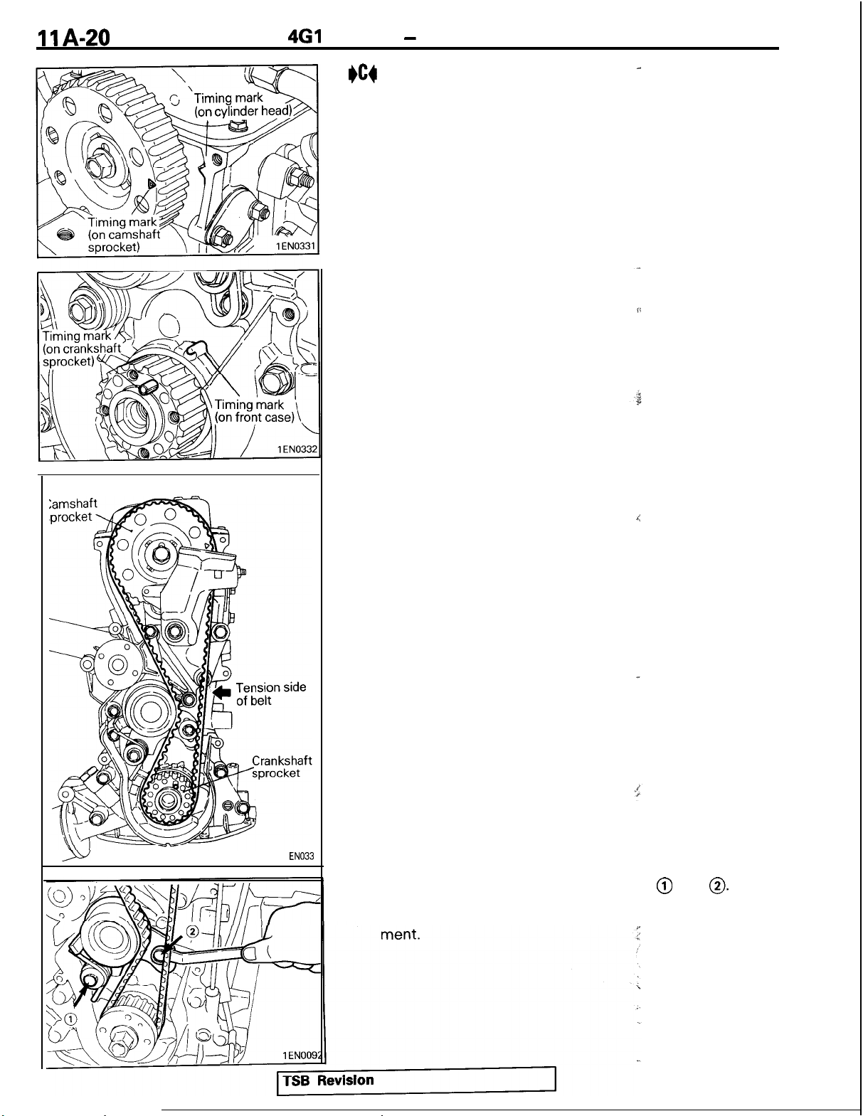
I)cg
TIMING BELT INSTALLATION
(1) Align the timing marks on the camshaft sprocket and the
crankshaft sprocket with their timing marks.
-
1
EN033
(2) Set the timing belt first on crankshaft sprocket and then
keeping the tension side belt tight, set on the camshaft
sprocket.
(3) Loosen the tensioner mounting bolts @ and
(4) Check that the belt completely meshes with the sprocket.
Also check the timing marks on the sprockets for align-
4
0.
Page 29

4Gl
ENGINE - Timina Belt
\
Tensioner slot side
il
1
ENOOOE
(5) Turn the crankshaft clockwise by 3 crankshaft
teeth.
(6) Tighten bolt @ first and then bolt 0. If bolt @ is tightened
first, the tensioner will turn together with the bolt, resulting
in an overtensioned belt.
(7) Check the belt tension. Hold the tensioner and ‘timing belt
together by hand and give the belt a slight thumb pressure
at a point level with tensioner center. Make sure that belt
cog crest comes as deep as about
slot side tensioner bolt head.
l/4
of the width of the
s@Cxket
I
ll4of
bolt head
1
EN025
TSB
Revision
Page 30

461
IIA-22
ENGINE - Fuel and Emission Parts
FUEL AND EMISSION PARTS
REMOVAL AND INSTALLATION
19 Nm
;;
14
ft.lbs.
TSB Revision
Removal steps
1.
Throttle body
2.
Gasket
3. Injectors and fuel rail
4.
eB4 ;.
*A4
*A4
Insulator
Fuw&ressure regulator
7:
Insulator
8. Injector clip
9.
Injector
10.
O-ring
11.
Grommet
12.
Fuel rail
13. EGR valve (For California)
14.
Gasket
1 EN0238
Page 31

461
ENGJNE - Fuel and Emission Parts
INSPECTION
INJECTORS
(1) Using an ohmmeter (circuit tester), test for,
between terminals of injector; the circuit should be closed.
If failure is detected, replace the injector.
Standard value: 13 - 16 Cn [at
6FU192C
EGR VALVE
(1) Check the EGR valve for sticking or carbon deposits.
If such conditions exist, clean or replace the EGR valve.
(2) Connect a hand vacuum pump to the nipple of the EGR
valve and plug the other nipple.
(3) Apply a vacuum of 500 mmHg (19.7
that vacuum is maintained. If there is a leak, replace the
EGR valve.
In addition, check the valve for its opening and closing
6EM038~
motion by applying and removing vacuum.
20°C (68”F)l
in.Hg)
to make sure
‘,.$
::.
:.
‘I’ ,L
cont$u~ty,
1
EN025C
INSTALLATION SERVICE POINTS
#A4
(1) Before installing an injector, the rubber O-ring must be
(2) Install injector top end into the fuel rail. Be
(3) Install injector clip by sliding open ends onto both injector
I)64
(1) Before installing the pressure regulator, the O-ring must be
INJECTORS / INJECTOR
lubricated with a
*drop
of clean engine oil to aid in
CLIP INSTALLATICjbi
installation.
careful
not
damage O-ring during installation.
and fuel rail.
FUEL PRESSURE REGULATOR INSTALLATION
lubricated
a drop of clean engine oil to aid in
yjth
installation.
to
6FUO71,
TSB Revision
Page 32

4Gl
1
M-24
ENGINE - Throttle Body
THROTTLE BODY
DISASSEMBLY AND REASSEMBLY
Up to 1992 models
1
2Nm
1.4 ftlbs.
Disassembly steps
4ArJ bA4 1.
From 1993 models
Throttle position sensor
2.
Idle
speed control motor
3. Throttle valve set screw
4. Throttle body
“p
2Nm
1.4
ft.lbs.
6FU1292
Disassembly steps
8:;
I)A4
I.
Throttle position sensor
2.
Idle arr
control motor
4BO
3. O-ring
4. Throttle body
5. Fixed speed adjusting screw
]
TSB Revision
1 EN0336
Page 33

461
ENGINE - Throttle Bodv
Closed throttle position switch*
Throttle
Throttle position
sensor output
*
From 1993 models
Dosition
Throttle position
sensor connector
DISASSEMBLY
6Ab
THROTTLE POSITION SENSOR AND
CONTROL MOTOR
SERVJCE
POINTS
/ IDLE
IDLE
SPEED
AIR CONTROL IMOTOR
REMOVAL
(1)
DO not disassemble the sensor and motor.
(2)
DO
not immerse in solvent the sensor and motor to clean.
Clean them with shop towel.
aB0
THROlTLE
BODY REMOVAL
(1) Do not remove the throttle valve.
(2) Check if the vacuum port or passage is clogged. Use
compressed air to clean the vacuum passage.
REASSEMBLY SERVICE POINT
/
round
View
P
7FUO535
P
+A4 THROTTLE
POSITION SENSOR INSTALLATION
(1) Check correct installation of the throttle position sensor.
While moving the throttle lever in both open and close
directions, check to see that resistance between terminals
@ and @ or @ and @ changes. If the resistance changes
smoothly, the throttle position sensor has been installed
correctly.
1 EN024S
TSB Revision
Page 34

llA-26
4Gl
ENGINE - Intake Manifold
INTAKE MANIFOLD
REMOVAL AND INSTALLATION
8Nm
Gft.!bs.
14
Nm
IO ft.lbs.
A*
Removal steps
I.
Water hose
eC4
2. Engine coolant temperature gauge unit
eB4
3. Engine coolant temperature sensor
*AiJ
4. Thermoswitch
5. Water outlet fitting
6. Water outlet fitting gasket
7. Thermostat
8. Outer cable bracket
9. Inner cable bracket
10.
Engine hanger
11. Thermostat housing
12. Intake manifold stay
13. Engine support bracket stay (From 1993
models)
14. Intake manifold
15. Intake manifold gasket
18Nm
13
ftlbs.
For
k:E
AIT
-18Nm
13
ft.lbs.
/
. .
[
TSB Revision
I
Page 35

Sealant
Sealant
4Gl
ENGINE
lEN033E
-
Intake Manifold
INSTALLATION SERVICE POINTS
#A4
SEALANT APPLICATION TO
Specified sealant:
3M
Nut Locking Part No. 4171 or equivalent
I)B4
SEALANT APPLICATION TO ENGINE COOLANT
-
TEMPERATURE GAUGE UNIT
Specified sealant:
3M ATD Part No. 8660 or equivalent
THERM0 SWIT&
,-
(” *f ‘; : i’<, ‘* ; *
. .
,,
Sealant
9EN009;
9EN0091
I)c4
SEALANT APPLICATION TO ENGINE COOLANT
TEMPERATURE SENSOR
Specified sealant:
3M
Nut Locking Part No. 4171 or equivalent
1
TSB Revision
Page 36

1
IA-28
461
ENGINE
Exhaust Manifold and Water
-
EXHAUST MANIFOLD AND WATER PUMP
REMOVAL AND INSTALLATION
14
10
Nm
ft.lbs.
Pump*
7
30 Nm
22
ft.lbs.
9Nm’
7 klbs.
1
-
14 Nm
10
ftlbs.
Removal steps
1.
Exhaust manifold cover “A”
2. Oxygen sensor - [1992,1993 (FED)
3. Engine hanger
4. Exhaust manifold
5. Exhaust manifold cover “B”
6. Exhaust manifold gasket
7. Water hose
+A4
8. Water inlet pipe
*AC
9. O-ring
10.
Water pump
11. Water pump gasket
models1
1 EN0339
TSB Revision
Page 37

4Gl
ENGINE - Exhaust Manifold and Water Pump
O-ring
I
Water inlet pipe
Water
pump
6EN0594
INSTALLATION SERVICE POINT
I)A4
WATER PIPE / O-RING INSTALLATION.
(1)
Wet the O-ring (with water) to
Caution
Keep the O-ring free of oil or grease
facilitateFas-6embly.
‘.‘ ) & p
:.
TSB
Revision
Page 38

1 IA-30
461
ENGINE
Rocker Arms and Camshaft
-
ROCKER ARMS AND CAMSHAFT
REMOVAL AND INSTALLATION
1.8Nm
1.3ft.lbs.
‘_
1
I
32
Nm
23
ft.lbs.
TSB Revision
Removal steps
1.
Breather hose
2. PCV hose
3. Rocker cover
4. Rocker cover gasket
)C4
5. Oil seal
6. Rocker arm and rocker arm shaft
eB4
7. Rocker arm and rocker arm shaft
#Bd
8. Rocker arm “D”
9. Wave washer
10. Spacer
11. Rocker arm “C”
12. Rocker arm shaft (exhaust side)
13. Rocker arm “B”
14. Rocker arm spring
15. Rocker arm “A”
16. Rocker arm shaft (intake side)
17. Adjusting screw
18. Nut
+A4
19. Camshaft
1
EN0340
Page 39

461
ENGINE - Rocker Arms and Camshaft
INSPECTION
CAMSHAFT
(1) Measure the cam height.
Standard value:
38.78
39.10 mm
38.28 mm (1.5071 in.)
38.60 mm (1.5197 in.)
1
EN009s
Intake
Exhaust
Limit:
Intake
Exhaust
ROCKER ARM
l
Check the roller surface. If any dents, damage or seizure is
evident, replace the rocker arm.
l
Check rotation of the roller. If it does not rotate smoothty or
if looseness is evident, replace the rocker arm.
l
Check the inside diameter. If damage or seizure is
replace the rocker arm.
l Check the screw end for wear. If considerable wear is
evident, replace the adjusting screw.
mti
(1.5268 ‘in.)
(1.53& Sii.)
qfq/&&l
.:-
_j
*
”
,
evident,
C
Timing belt side
Wave washer
Bolt hole
center
1
EN005:
1 EN0342
INSTALLATION SERVICE POINTS
I)A4
CAMSHAFT INSTALLATION
(1)
Position the dowel pin of the camshaft as shown in the
illustration.
I)B4
(1)
ROCKER ARM AND ROCKER ARM SHAFT
INSTALLATION
install
the rocker arm shaft assembly wnlle
respecuny LIW
illustrated positions.
NOTE
Make sure that the bolt hole center is offset toward the
indicated side with respect to the rocker arm shaft
centerline.
. .
+c4
TSB Revision
OIL SEAL INSTALLATION
Page 40

1
IA-32
4Gl
ENGINE
-
Rocker Arms and Camshaft
Intake 1 Intake 2
/
Exhaust 1
’ /
Exhaust 2
Exhaust 3
Exhaust 4
lEN015t
lEN0122
VALVE CLEARANCE ADJUSTMENT
~
(1) Position the No. 1 cylinder at the top dead center on
compression stroke.
(2) Adjust the valve clearance at the points shown in the
illustration.
(3) Loosen the adjusting screw locknut’.
(4) Using a feeler gauge, adjust the valve clearance by turning
the adjusting screw.
Standard value: on cold engine
Intake
Exhaust
0.07 mm
0.09 mm
0.17 mm
(.0028
(.0035
(.0067
in.) Up to 1992 models
in.) From 1993 models
in.)
(5) While holding the adjusting screw with a screwdriver,
tighten the lock nut.
(6) Rotate clockwise the crankshaft one complete turn (360”
1
degrees).
(7) Adjust the valve clearance at the points shown in the
illustration.
(8) Repeat steps (3) to (5) to adjust the valve clearance of
remaining valves.
Intake 3 Intake 4
-.----
lEN0156
TSB Revision
Page 41

4Gl
ENGINE - Cylinder Head and Valves
CYLINDER HEAD AND VALVES
REMOVAL AND INSTALLATION
2-
73 Nm
53
ft.lbs.
Removal steps
(JAI) #E4
(IBI) #Q
(IBM) bC4
$I$ #A4
@I$ #A4
1. Cylinder head bolt
2. Cylinder head, valve assembly
I)D4
3. Cylinder head gasket
4. Retainer lock
5. Valve spring retainer
#B4
6. Valvespring
7. Intake valve (primary)
8. intake valve (secondary)
9. Retainer lock
10.
Valve spring retainer
+B4
11. Valve spring
12. Exhaust valve
13. Valve stem seal
14. Valve spring seat
15. Valve stem seal
16. Valve spring seat
17. Intake valve guide
18. Exhaust valve guide
19. Intake valve seat (primary)
20.
Intake valve seat (secondary)
21. Exhaust valve seat
22. Cylinder head
1ENOlOl
TSB Revision
Page 42

1 IA-34
461
ENGINE - Cvlinder Head and Valves
REMOVAL SERVICE POINTS
(IAN
CYLINDER HEAD BOLT REMOVAL
OBo
RETAINER LOCK REMOVAL
(1) Store the removed valves, springs and other parts, tagged
to indicate their cylinder No. and location to aid reassembly.
j
$0
(1) Do not reuse removed valve stem seals.
INSPECTION
CYLINDER HEAD
(1) Check the cylinder head gasket
(2) If the service limit is exceeded, correct to meet specifica-
TSB Revision
VALVE STEM SEAL REMOVAL
&$-face
using a straightedge and
Standard value: 0.05 mm
Limit: 0.2 mm
tion.
Grinding limit:
* Total resurfacing depth of
cylinder block
Cylinder head height
106.9
-
(.008
*0.2 mm
107.1 mm (4.209 - 4.217 in.)
thicknessygauge.
(.0020 jn.)
in.)
(.008 ind
bo$
(Specifieatidn
i:
;-
".
.,
for flatness by
>:
cylinder head and
when new):
Page 43

4Gl
ENGINE - Cylinder Head and Valves
VALVE
(1) Check the valve face for correct contact. If incorrect, reface
using valve
refacer.
Valve
should“ma,ke
a uniform contact
with the seat at the center of valve ‘face.
(2) If the margin is smaller than the
ser@cefimit,
replace the
valve.
Standard value:
1.0
6EN054:
Intake
Exhaust
1.5
Limit:
Intake 0.5 mm
Exhaust
1.0
mm
mm
mm
(.039
(.059
(.020
(.039
in.)
in.)
in.)
in.)
VALVE SPRING
(1) Measure the free height of the spring and, if it is smaller
than the limit, replace.
Free
height
Standard value:
Intake
Exhaust
46.1 mm
(1.815
in.)
48.8 mm (1.643 in.)
Limit:
Intake
1
I
EN0264
Exhaust
45.1 mm
45.8 mm
(1.776
(1.803
in.)
in.)
(2) Measure the squareness of the spring and, if the limit is
exceeded, replace.
Standard value: 2” or less
Limit: 4”
Valve
guide
0.9 -1.3 mm 0.9 -1.3 mm
(.035-
,051
in.)
Exhaust
44” 44”
(.035-
Intake
1
EN027!
,051
in.)
T
1
EN01 71
TSB Revision
VALVE GUIDE
(1)
Measure the clearance between the valve guide and the
valve stem. If the limit is exceeded, replace the valve guide
or the valve, or both.
Standard value:
Intake
Exhaust
0.02 - 0.05 mm
0.05 - 0.09 mm
(.OOOS -
JO20 in.)
(.0020 - .0035 in.1
Limit:
Intake
Exhaust
0.10 mm
0.15 mm I.0059 in.)
(.0039
in.)
VALVE SEAT RECONDlTlONlNG PROCEDURE
(1)
Before attempting reconditioning of the valve seat, check
the valve guide-to-valve stem clearance and replace the
valve guide if necessary.
(2) Recondition to the specified seat width and seat angle.
(3) After reconditioning, fit up the valve and valve seat using
lapping compound.
Page 44

1
IA-36
4Gl
ENGINE - Cylinder Head and Valves
0.5 - 1 mm
Oversize I.D.
f.02 - .04
in.)
0.5-
1 mm
(.02 - .04
I
in.)
1
EN0275
VALVE SEAT REPLACEMENT PROCEDURE
(1)
Cut the
valve
seat to be replaced from the inside to thin the
wall thickness. Then, remove the valve seat.
(2) Rebore the valve seat hole in cylinder head to a selected
oversize valve seat diameter.
Seat ring hole diameter: See “Service Specifications”
in page
(3) Before fitting the valve seat, either
up to approximately
using cooling spray, to prevent the
llA-6
250°C (482°F)
&at
the cylinder head
or cool the valve seat
cy%nder
head bore from
galling.
(4) Using valve seat cutter, correct
tie
valve seat to the
specified width and angle. See “VALVE SEAT RECONDITIONING PROCEDURE.”
VALVE GUIDE REPLACEMENT PROCEDURE
(1) Push out the valve guide toward the combustion chamber
side using a press.
(2) Rebore the valve guide hole in the cylinder head to the size
corresponding to the oversize valve guide to be installed.
Caution
Do not install a valve guide of the same size again.
Valve guide hole diameter: See “Service Specifica-
tions” in page
IIA-6
(3) Install the valve guide until it projects 17 mm
1ENOlOf
REASSEMBLY SERVICE POINTS
+A4
(1) Install the valve spring seat.
(2) The special tool must be used to install the valve stem seal.
TSB Revision
(67
in.) from
the cylinder head as illustrated.
NOTE
(1)
The valve guide must be installed from the upper side of
the cylinder head.
(2) Note that the intake and exhaust valve guides differ in
length: 44 mm (1.732 in.) on intake side, 49.5 mm
(1.949 in.) on exhaust side.
(3) After installation of the valve guide, install a new valve
and check that it slides
smoothly.
VALVE STEM SEAL INSTALLATION
Improper installation could result in oil leaking past the valve
guide.
Caution
Do not reuse removed valve stem seal.
;
c
Page 45

Painted end
4Gl
ENGINE - Cylinder Head and Valves
+B4
I
Spring retainer
VALVE SPRING INSTALLATION
(1)
~.s$~~;~
valve spring with the painted end on the rocker
_
Stem seal
Spring seat
6EN043i
I)c4
RETAINER LOCK INSTALLATION
(1) The valve spring, if excessively compressed, causes the
bottom end of retainer to be in contact with, and damage,
the stem seal.
+
+-
Timing belt side
I
Timing belt side
Identification mark
1
FNOlill
lEN0109
TSB
I)D4
(1) Clean both gasket surfaces of cylinder block and cylinder
(2) Do not apply sealant.
(3) Confirm the identification mark on cylinder head gasket.
I)E4
(1)
(2) Repeat the tightening sequence several times, and torque
Revision
CYLINDER HEAD GASKET
INSTALLATlON
head.
The identification mark is stamped on the top surface of the
gasket at its front end.
Identification mark
3Vll: Up to 1992 models
1CG:
From 1993 models
CYLINDER HEAD BOLT INSTALLATION
Using the special tool and a torque wrench, tighten the
bolts in the shown sequence.
the bolts to specification in the final sequence.
Page 46

1 IA-38
461
ENGINE - Cvlinder Head and Valves
TSB Revision
Page 47

4Gl
ENGINE - Front Case and Oil Pump
FRONT CASE AND OIL PUMP
REMOVAL AND INSTALLATION
45 Nm
33
ft.lbs.
I
7
Removal steps
eD4
1. Oil filter
2.
Drain plug
QAI$~C~
@I) +A4
@I) +A4
3. Drain plug gasket
4. Oil pan
5.
Oil screen
6. Oil screen gasket
7.
Relief plug
8.
Gasket
9.
Relief spring
10.
+B4
Relief plunger
11. Oil seal
12.
Front case
13. Front case gasket
14. Oil pump cover
15. Outer rotor
16. Inner rotor
TSB
lEN0165
Revision
Page 48

1
IA-40
4Gl
ENGINE - Front Case and Oil
Puma,
lEN008t
REMOVAL SERVICE POINTS
OAo
OIL PAN REMOVAL
1
(1) Knock the special tool deeply between the oil pan and the
cylinder block.
(2) Hitting the side of the special tool, slide the special tool
along the oil pan to remove it.
OBo
(I)
OUTER ROTOR / INNER ROTOR REMOVAL
Make alignment marks on the outer and inner rotors for
reference in reassembly.
INSPECTION
OIL PUMP
(1)
Check the tip clearance.
Standard value: 0.03 - 0.08 mm
.?
(.00?2 - .0031 in.)
TSB
(2) Check the side clearance.
(3) Check the body clearance.
Revision
Standard value: 0.04 - 0.10 mm
(.0016 - .0039
!
fI
?
?’
Standard value: 0.10 - 0.18 mm I.0039
Limit: 0.35
(.138
in.)
“,
i
:s
P
E
I
-
.0071
in.)
in.)
Page 49

4Gl
ENGINE - Front Case and Oil Pump
INSTALLATION SERVICE POINTS
I)A4
(1) Install the outer rotor in the same direction as before noting
INNER ROTOR / OUTER ROTOR INSTALLATION
the mark put at the time of removal. Apply engine oil to the
entire rotor surface.
I
MD998305 n’
lEN00801
eB4
\
(1) Set the special tool on the crankshaft front end and apply
CRANKSHAFT FRONT OIL SEAL INSTALLATION
engine oil to its outer circumference.
(2) Apply a light coat of engine oil to the oil seal lip and then
slide the oil seal down along the special tool by hand until it
touches the front case. Install the oil seal in the front case
using the other special tool.
TSB Revision
Page 50

4Gl
ENGINE
-
Front Case and Oil
I)c4
OIL PAN INSTALLATION
(1) Scrape clean or wire brush all
Puma
gask{t
surfaces removing all
loose material.
(2) Apply a 4 mm
pan flange.
Specified sealant:
Mitsubishi Genuine Part No.
lent
(16
in.) diameter
beid
of sealant to the oil
.F
1
‘%lD970389
or equiva-
i.
(3) The oil pan should be installed within 15 minutes after the
application of sealant.
4 mm
(.I
based sealant
6 in.) diameter
Groove
portion
Bog,hole
po
+on
t
;
J
I)04
OIL FILTER INSTALLATION
(1) Clean the filter installation surface of the filter bracket.
(2) Apply engine oil to the O-ring of the oil filter.
(3) Screw the oil filter on the bracket until the O-ring contacts
the base. Then tighten one additional turn.
TSB Revision
Page 51

4Gl
ENGINE- Piston and Connecting Rod
PISTON AND CONNECTING ROD
REMOVAL AND INSTALLATION
yl&g
. .
Removal steps
OAo $1 k khecting
3. Connecting rod bearing
*iI4
4. Piston and connecting rod
5. Connecting rod bearing
eC4
6. Piston ring No. 1
eC4
7. Piston ring No. 2
I)B4
8. Oil ring
oBoeA 9. Piston pin
10.
Piston
11. Connecting rod
12. Bolt
rod cap
TSB Revision
-
‘.
1
EN0245
Page 52

IlA-44
4Gl
ENGINE
-
Piston and Connecting Rod
Piston pin setting tool
ylinder No.
MIT21
6941
DENOOM
DISASSEMBLY
OAo
CONNECTING ROD CAP REMOVAL
(1)
Mark the cylinder number on the side of the connecting rod
big end for correct reassembly.
(IBM
PISTON PIN REMOVAL
Item
No.
1
2
3
4
5
6
7
8
9
10
11
,SERVlCE
Part No.
MIT310134
MIT310136
MIT310137
MIT310138
MIT310139
MIT310140
MIT310141
MIT310142
M IT48
143
2 16943
10396
POINT6
Description
Base
Piston Support
Connecting Rod Guide Pin
Connecting Rod Guide Pin
Connecting Rod Guide Pin
Piston Support
Connecting Rod Guide Pin
Piston Support
Press Pin
Stop Screw
Nut
Press pin
$Mgg
h
, Piston pin
Front mark
Connecting rod
de
pin
7EN042E
(2) Select the correct piston support for your
above.) Fit the piston support onto the base. Place the base
on the press support blocks.
(3)
Insert
the press pin through the piston pin hole. Select the
correct connecting rod guide pin. (See above.) Thread the
guide pin onto the threaded portion of the press pin.
(4) Position the piston assembly on the piston support in the
press. With the press pin up as shown in the illustration,
insert the guide pin through the hole in the piston and
through the hole in the piston support.
(5)
Press the piston pin out of the assembly.
IMPORTANT: To avoid piston damage,
l
The piston support must seat squarely against the
piston.
l
Verify that the piston pin will
in the piston support.
(6)
Remove the piston pin from the
qide
f$ess
applrcatron.
9
through the hole
pin.
1
(See
7EN042E
ivision
Page 53

Piston
kg
End gap
5EN0066
6EN0548
INSPECTION
PISTON RING
(1)
Check for side clearance.
If the limit is exceeded, replace the ring or piston, or both.
Standard value:
No. 1
No. 2
Limit: 0.1 mm
0.03 - 0.07 mm (A012 -
0.02 - 0.08 mm
(.004
in.)
(&IO8 - .0024.‘in.)
(2) insert the piston ring into the cylinder bore. Force the ring
down with a piston, the piston crown being in contact with
the ring, to correctly position it at right angles to the cylinder
wall. Then, measure the end gap with a
If the end gap is excessive, replace the piston ring.
Standard value:
No. 1
No. 2
Oil
0.20 - 0.40 mm
0.20 - 0.35 mm
0.20 - 0.70 mm
(.0079 - .0157
(-0079 - .0138
(.0079 - .0276
Limit:
No. 1, No. 2 0.8 mm
Oil
1.0 mm
(.031
(.038
in.)
in.)
.0028 h.)
thickne$s
in.)
in.)
in.)
gauge.
&llT;E;yFT
(1)
Remove oil from crankshaft pin and connecting rod bearing.
PlN
OIL CLEARANCE (PLASTIC GAUGE
(2) Cut the plastic gauge to the same length as the width of
bearing and place it on a crankshaft pin in parallel with its
axis.
(3)
Install the connecting rod cap carefully and tighten the bolts
to specified torque.
(4) Carefully remove the connecting rod cap.
(5) Measure the width of the plastic gauge at its widest part by
using a scale printed on the plastic gauge package.
Standard value: 0.02 - 0.05 mm
Limit: 0.1 mm
(.004
in.)
(.OOOS - AI020
in.)
1
TSB Revision
I
Page 54

11 A-46
4Gl
ENGINE
-
Piston and Connecting Rod
7EN0421
REASSEMBLY SERVICE
I)A4
PISTON PIN INSTALLATION
(I)
Thread the stop screw and lock nut
Fit the correct piston support on the top of the base.
the press pin, threaded end up, into
support until the press pin touches
(2) Using the graduations on the press
POINTS-
asiembly
,’
into the base.
t?re
hole in the piston
e
stop screw.
n,
adjust the stop
Insert
screw to the correct depth of 49 mm (1.93 in.)
(3) Place the base on the press support blocks.
(4) Slide the piston pin over the threaded end of the press pin,
and thread the correct guide pin up against it.
(5) Coat the piston pin with oil, and with the connecting rod
held in position, slide the guide pin through the piston and
the connecting rod.
(6) Press the piston pin through the connecting rod until the
guide pin contacts the stop screw.
(7) Remove the piston assembly from the base. Remove the
guide pin and the press pin from the assembly.
IMPORTANT: Due to production tolerance variations, it
is necessary to visually inspect t@ piston pin depth
after installation to verify that the piston pin is
centered. Adjust if necessary.
‘*
7EN042:
TSB Revision
3
Page 55

4Gl
ENGINE - Piston and Connecting Rod
*6+
OIL RING INSTALLATION
(1)
Fit the oil ring spacer into the piston ring groove.
NOTE
The side rails and spacer may be installed in either direction.
I
1
EN027;
Side rail gap
1
EN026E
7EN045:
(2) Install the upper side rail.
To install the side rail, first fit one end of the rail into the
piston groove, then press the remaining portion into
position by finger. See illustration.
Caution
Do not use piston ring expander when installing the
side rail.
(3) Install the lower side rail in the same procedure as
described in step (2).
(4) Make sure that the side rails move smoothly in either
direction.
I)c4
PISTON RING No. 2 / PISTON RING
iuo.
1 IN-
STALLATION
(1)
Using piston ring expander, fit No. 2 and then No. 1 piston
ring into position.
NOTE
(1) Note the difference in shape between
No.‘l,
and No. 2
piston rings.
(2) Install piston rings No. 1 and No. 2 with their side having
marks facing up (on the piston crown side).
-l
No. 2
and
spa&gap
,
No. 1
I
rinq qap
Identification mark
stamped
1’
Barrel
type
Identification mark stamped
1
L
No. 2
Taper type
1
No.
6EN054!
TSB Revision
EN027t
1
side
I)D4
PISTON AND CONNECTING ROD ASSEMBLY IN-
STALLATION
(1)
Apply engine oil to the piston surface, piston rings, and oil
ring.
(2) Align the gaps of piston rings and oil ring (side rails and
spacer) as shown in the illustration.
Page 56

IlA-48
461
ENGINE
-
Piston and Connecting Rod
Timing belt
c3
side
ront mark
1
EN0247
(3) Rotate crankshaft so that the crank
pi^n
is on the center of
the cylinder bore.
(4) Use suitable thread protectors on
theconnecting
rod bolts
before inserting piston and connecting rod assembly into
the cylinder block.
Care must be taken not to nick the crank pin.
(5) Using a suitable piston ring compressor. tool, install the
piston and connecting rod assembly
I)E4
CONNECTING ROD CAP
(1) Verifying the mark made during
ir#o
the cylinder block.
INST&LLATION
dis$ssembly,
install the
bearing cap to the connecting rod. If the connecting rod is
new with no index mark, make sure
notches come on the same side
th@
the bearing locking
as-,
shown.
e
(2) Make sure that connecting rod big end side clearance
meets the specification.
Standard value: 0.10 - 0.25 mm
Limit: 0.4 mm
(.018
in.)
f.0039 - .00!38
3
in.)
I)F4
(1) Since the connecting rod bolts and nuts are torqued using a
(2) Install the connecting rod cap on the big end of connecting
(3) Before installing the nuts the threads-should be oiled with
(4) Install both nuts on each bolt finger tight, then alternately
(5) Tighten the nuts to 20 Nm (14.5
TSB Revision
CONNECTING ROD CAP NUT
[NSTALLATION
new procedure, they should be examined BEFORE reuse. If
the bolt threads are “necked down” the bolts should be
replaced.
Necking can be checked by running a
I”
&rt
with fingers to the
full length of the bolt’s thread. If the nut does not run down
smoothly the bolt should be replaced.
rod.
engine oil.
torque each nut to assemble the cap properly.
ft.lbs.)
and plus
l/4
(90”)
turn.
t
Page 57

461
ENGINE
-
Crankshaft, Flywheel and Drive Plate
CRANKSHAFT, FLYWHEEL AND DRIVE PLATE
REMOVAL AND INSTALLATION
., 135.Nm
19 Nm
l4 fi*‘bfm
184%
11 Nm
8
ft.lbs.
8
I fL
.Y fths-
Al,
3
\
135Nm
- 6 ft.lbk.
53 Nm
38
1
TSB Revision
I
ft.lbs.
Removal steps
1.
Flywheel bolt
2.
Flywheel
3. Drive plate bolt
4.
Adaptor plate
5.
Drive plate
6.
Adaptor plate
7.
Crankshaft bushing
8. Rear plate
9. Bell housing cover
10. Oil seal case
11.
Oil seal case gasket
*Cl4
12.
Rear oil seal
13. Bearing cap bolt
*C4
14. Bearing cap
#B+
15. Crankshaft bearing, lower
16. Crankshaft
@B4
17. Crankshaft bearing, upper
#A4
18. Oil pressure switch
19. Cylinder block
I
For MIT
1
EN343
Page 58

1
IA-50
461
ENGINE
-
Crankshaft, Flywheel and Drive Plate
INSPECTION
CRANKSHAFT JOURNAL OIL CLEARANCE (PLASTIC
GAUGE METHOD)
(1) Remove oil from the crankshaft journal and the crankshaft
bearing.
(2) Install the crankshaft.
(3) Cut the plastic gauge to the same length as the width of
bearing and place it on the journal in parallel with its axis.
6EN055C
(4) Install the crankshaft bearing cap carefully and tighten the
bolts to the specified torque.
(5) Carefully remove the crankshaft bearing cap.
(6)
Measure the width of the plastic gauge at its widest part by
using a scale printed on the plastic gauge package.
Standard value: 0.02 - 0.05 mm
Limit: 0.1 mm
(.004
in.)
rr,
(.OOOS - .0020
in.)
;
i;
CYLINDER BLOCK
(1)
Using a straightedge and feeler
surface for
warpage.
Make sure
gaugzcheck
thagthe
the block top
surface is free
from gasket chips and other foreignimatters.
Standard value: 0.05 mm
Limit: 0.1 mm
(004
in.)
(.002
in.)
(2) If the distortion is excessive, correct within the allowable
limit or replace.
Grinding limit: 0.2 mm
(.008
in.)
The total resurfacing depth of both cylinder block
and mating cylinder head is 0.2 mm
maximum.
$
(008
in.) at
Cylinder block height (When new)?
Al
B
0
(3) Check cylinder walls for scratches
255.9 - 256.1 mm
(10.075 - lO~iO88
and
seizure. If defects
in.)
are evident, correct (rebore to an oversize) or replace.
(4) Using cylinder gauge, measure the’ cylinder bore and
cylindricity. If worn badly, correct the cylinder to an oversize
and replace the piston and piston rings. Measure at the
points shown in illustration.
i
Standard value:
Cylinder I.D.
75.50
75.53 mm
-
(2.9724 - 2.9736 in.)
Cylindricity: 0.01 mm
(0004
in.) or less
TSB Revisipn
Page 59

4Gl
ENGINE - Crankshaft, Flywheel and Drive Plate
BORING CYLINDER
(1) Oversize pistons to be used should be determined on the
basis of the largest bore cylinder.
Piston size identification
Thrust
direction
6EN055
Size
0.50
0.75
1
.OO
mm
(.02 in.) O.S.
mm
(.03
mm
(.04
in.)
in.)
OS.
OS.
Identification
0.25
0.50
0.75
1 .oo
I-
NOTE
Size mark is stamped on the piston top.
(2) Measure outside diameter of piston to be used. Measure it
in thrust direction as shown.
(3) Based on the measured piston O.D. calculate the boring
finish dimension.
I,:“.
Boring finish dimension = Piston O.D. + (clearance
between piston O.D. and cylinder) - 0.02 mm
(.OOOS
in.)
(honing margin)
(4) Bore all cylinders to the calculated boring finish dimension.
Caution
To prevent distortion that may result from temperature
rise during honing, bore cylinders, in this order: No. 2
to No. 4 to No. 1 to No. 3.
(5) Hone to the final finish dimension [piston O.D. + clearance
between piston O.D. and cylinder.]
(6) Check the clearance between piston and cylinder.
Clearance between piston and cylinder:
0.02 - 0.04 mm
(.OOOS - .0016
in.)
NOTE
When boring cylinders, finish all of four cylinders to the
same oversize, Do not bore only one cylinder to an
oversize.
lwer
Grooveless
bearing
Upper and lower bearings
(for No.
3)
Upper bearing
(for No.
1.2.4.5)
9EN0094
1
EN027
TSB
INSTALLATION SERVICE POINTS
*A+
(1)
+B4
(1)
(2) No. 1, 2, 4 and 5 lower bearings (cap side) are not provided
(3) No. 3 bearings are flanged and provided with no groove.
Revision
SEALANT APPLICATION TO OIL PRESSURE
SWITCH
Coat the threads of switch with sealant before
installirlg
the
switch.
Specified sealant: 3M ATD Part No. 8660 or equivalent
Caution
1. Keep the end of threaded portion clear of sealant.
2. Avoid an overtightening.
CRANKSHAFT BEARING INSTALLATION
No. 1, 2, 4 and 5 upper bearings (cylinder block side) are
provided with oil groove.
with oil groove.
Common bearings are used on the cap side and cylinder
block side.
Page 60

11
A-52
Timing
belt side
401
ENGINE - Crankshaft, Flywheel and Drive
I)c4
INSTALLATION OF BEARING
(1) Install according to the front mark end cap No.
NO174
Cap No.
1
EN017E
Pla$
CAP
Oil seal
Oil seal case
1
EN028C
1
EN027:
(2) After installing the bearing caps, make sure that the
crankshaft turns smoothly and the end play is correct. If the
end play exceeds the limit, replace crankshaft bearings.
Standard value: 0.05 - 0.18 mm
Limit: 0.3 mm
eD4
OIL SEAL INSTALLATION
(.012
in.)
(.0020 - .0071
in.)
TSB Revision
Page 61

4Gl
BRACKET
REMOVAL AND INSTALLATION
65
Nm
47
ft.lbs.
2
60
Nm
44
36
26
ft.1bs.h
Nm
ft.lbs.
1
/--+GFL
yy
ENGINE - Bracket
l.lA-53
Removal steps
1.
Exhaust pipe support bracket
2. Engine support bracket, front
3. Roll stopper bracket, front
4. Roll stopper bracket, rear
120
Nm
67
ftlbs.
‘\
TSB Revision
1
EN0347
I
Page 62

NOTES
Page 63

ENGINE
4637
CONTENTS
BRACKET
CRANKSHAFT, FLYWHEEL AND
DRIVE PLATE
CYLINDER HEAD AND VALVES
EXHAUST MANIFOLD AND
WATER PUMP
FRONT CASE, OIL PUMP AND OIL PAN
FUEL AND EMISSION
GENERAL INFORMATION
GENERAL SPECIFICATIONS
. . . . . . . . . . . . . . . . . . . . . . . . . . . . . . . . . . . . . . . . . . . . . . . . . . . . . . . . . . . .
. .
.._..............._...._..............................
f.......................
. . . . . . . . . . . . . . . . . . . . . . . . . . . . . . . . . . . . . . . . . . . . . . . . . . . .
PARTS
. . . . . . . . . . . . . . . . . . . . . . . . . . . .
. . . . . . . . . . . . . . . . . . . . . . . . . . . . . . . .
. . . . . . . . . . . . . . . . . . . . . . . . . . . .
62
58
39
32
. . . . . . . .
45
26
‘2
5
GENERATOR AND IGNITION SYSTEM
INTAKE
PISTON AND CONNECTING ROD
ROCKER ARMS AND CAMSHAFT
SEALANT
SERVICE SPECIFICATIONS
SPECIAL TOOLS
THROTTLE BODY
TIMING
TORQUE SPEClklCATlONS
MANIFOLD
................................................................
BELT
........................................................
............................................
....................
..........:.........
................................
....................................................
................................................
....................
........
..........
/.
16
30
52
34
12
6
13
28
18
10
Page 64

IIB-2
4G3
ENGINE - General Information
GENERAL INFORMATION
ENGINE SECTIONAL VIEW
1
TSB Revision
3ENOO86
I
Page 65

4G3
ENGINE - General Information
pqJp3
I
\
TSB Revision
3EN0087
Page 66

IIB-4
JBRICATION SYSTEM
4G3
ENGINE - General Information
TSB Revision
3LUOO20
Page 67

4G3
ENGINE
GENERAL SPECIFICATIONS
-
General Specifications
ptgpg
Description
Type
Number of cylinders
Combustion chamber
Total displacement
Cylinder bore
Piston stroke
Compression ratio
Valve timing:
( 1:
camshaft identification mark
Intake valve
Opens
Closes
Exhaust valve
Opens
Closes
Lubrication system
Oil pump type
Cooling system
Water pump type
EGR type
Injector type and number
Injector identification mark
Fuel regulated pressure
Throttle bore
Throttle position sensor
Closed throttle position switch
cm3
mm (in.)
mm (in.)
mm (in.)
(cu. in.)
kPa
(psi)
Specifications
In-line OHV, SOHC
4
Compact type
1.755 (107.10)
80.6 (3.17)
86 (3.39)
9.0
(AR)
20” BTDC
52” ATDC
55” BBDC
17” ATDC
Pressure feed, full-flow filtration
Involute gear type
Water-cooled forced circulation
Centrifugal impeller type
Single type
Electromagnetic 4
N210H
335 (47.6)
50 (1.969)
Variable resistor type
Contact type, within idle speed control motor
““:’:
:
: .///,.’
.
-_
.I-.: :_
I .,
.-
Page 68

IIB-6
4G3
ENGINE - Service Specifications
SERVICE SPECIFICATIONS
Standard
Cylinder head
Flatness of gasket surface
Grinding limit of gasket surface
*
Total resurfacing depth of both cylinder head
and cylinder block
Overall height
Oversize rework dimensions of valve
guide hole
(both intake and exhaust)
0.05
(002)
0.25
(.OlO)
0.50 (020)
Oversize rework dimensions of intake valve
seat ring hole
0.30 (012) 43.30 - 43.33
0.60
(024)
Oversize rework dimensions of exhaust
valve seat ring hole
0.30
(012)
0.60
(.024)
0.05
(.0020)
88.4 - 88.6 (3.480 -
13.05-
13.25 - 12.27
13.50-
43.60-43.63(1.7165-1.7177)
37.30 -37.33 (1.4685 - 1.4697)
37.60 - 37.63 (1.4803 -
13.07
13.52
3.4881
(.5138-.5146)
(5217 - 95224)
(.5315-.5323)
(1.7047 -
1.7059)
1.4815)
i
7
t
mm (in.)
Limit
0.2
(.008)
“0.2 (008)
Camshaft
Cam height 35.91 (1.4138)
Fuel pump driving cam diameter
Journal diameter
Oil clearance
Rocker arm
I.D.
Rocker arm-to-shaft clearance 0.01 - 0.04
Rocker shaft
O.D.
Overall length
Intake
Exhaust
40
(1.57)
33.94 - 33.95 (1.3362 -
0.05 - 0.09
18.91 - 18.93
18.89-
365.5
350.0
(0020 - .0035)
(.0004 - .0016)
18.90
(14.035)
(13.780)
1.3366)
(.7444 - .7453)
(7437 - .7440)
.I
c
_
<
i
35.41 (1.3941)
39.5 (1.555)
0.1
(.004)
1
TSB Revision
1
Page 69

463
ENGINE - Service Specifications
mm (in.)
Standard
Valve
Overall length
Intake
Exhaust
Stem diameter
Intake
Exhaust
Face angle
Thickness of valve
head (margin)
Intake
Exhaust
Stem-to-guide
clearance
Intake 0.03 - 0.06
Exhaust
Valve spring
Free height
Load/installed height
Out-of-squareness
N/mm
(Ibs./in.)
98.2 (3.866)
95.5 (3.760)
7.96-7.98(.313-.314)
7.93 - 7.95
45” - 45”30’
1.2
(.047)
1.5
(.059)
0.05 - 0.09
49.2 (1.937)
31
O/37.3
Max. 2”
(.312 - ,313)
(0012 - .0024)
(.0020 - .0035)
(68/l
.469)
Limit
I
c’:,;
*‘:’ ;, :,i :;
0.7
1 .o
0.10
0.15
48.2 (1.896)
4”
.-y >,-;
(.028)
i.039)
(.0039)
c.qaq$l)
. .
,.
,.
,
Valve guide
Overall length
Intake
Exhaust
I.D.
O.D.
Service size
Press-in temperature
Valve seat
Seat angle
Valve contact width
Sinkage
service
size
44 (1.73)
48 (1.89)
7.2 -7.25
13.06-13.07(.5142-.5146)
0.05
Room temperature
43”30’ - 44”
0.9 - 1.3
0.3
(.2835 - .2854)
(.002),
0.25
(.035 - .051)
(.OlZ),
0.6 (024) oversize
(.Ol),
0.50
(.02)
oversize
0.2
,!
4
(.008)
1
TSB Revision
Page 70

463
ENGINE - Service
SDecifications
mm (in.)
Silent shaft
Journal diameter
Right(front)
(rear)
Left (front)
(rear)
Oil clearance
Right(front)
(rear)
Left
Ifrar$)
r
Piston
O.D.
Piston-to-cylinder clearance
Service size
Piston ring
End gap
No. 1 ring
No. 2 ring
Oil ring
Ring-to-ring groove clearance
No. 1 ring
No. 2 ring
Service size
Standard
38.96 - 38.98 (1.5339 - 1.5346)
35.95 - 35.97 (1.4154 -
18.47 - 18.48
35.95 - 35.97 (I
0.02 - 0.06
0.05 - 0.09
0.02 - 0.05
0.05 - 0.09
80.57 - 80.60 (3.1720 - 3.1732)
0.02 - 0.04
0.25
(.Ol),
0.30-0.45(.0118-.0177)
0.20-
0.35 (.0079 -
0.20 - 0.70
0.05 - 0.09
0.02 - 0.06
0.25
(.Ol),
(.7272 - .7276)
.4154- 1.4161)
(.0008 - .0024)
(.0020 - .0035)
(.0008 - .0020)
(.0020 - .0035)
(.0008 - .0016)
0.50
(.02),
LOO79 - .0276)
(.0020 - .0035)
(.0008 - .0024)
0.50
(.02),
0.75
.0138)
0.75
1.4161)
(.03), 1.OO
(.03), 1.OO
(.04)
(.04)
oversize
oversize
Limit
0.8
(.031)
0.8
(.031)
1 .o(.039)
Piston
pin
O.D.
Press-in load N
Press-in temperature
Connecting rod
Big end center-to small end center length
Bend
Twist
Big end side clearance
(Ibs.)
19.00 - 19.01
5,000 - 15,000 (I, 102 - 3,307)
Room temperature
153.6 - 153.7 (6.047 -
0.05
(.0020)
0.1
(.004)
0.10 - 0.25
(.7480 - .7484)
6.051)
(.0039 - .0098)
0.4
(.OI 6)
TSB Revision
Page 71

463
ENGINE - Service Specifications
Crankshaft
End play
Journal O.D.
Pin O.D.
Out-of-roundness and taper of journal
and pin
Oil clearance of journal
Oil clearance of pin
Journal undersize
0.25
(.OlO)
U.S.
0.50
(.020)
U.S.
0.75
(.030)
U.S.
Pin undersize
0.25
(.OlO)
U.S.
0.50 (020) U.S.
0.75
(.030)
U.S.
Cylinder block
I.D.
Flatness of gasket surface
Grinding limit of gasket surface
*
Total resurfacing depth of both cylinder block
and cylinder
Dverall
height
head
Standard
0.05-0.18(.0020-.0071)
57 (2.24)
45 (1.77)
Within 0.01 (0004)
0.02-0.05 (.0008- .0020)
0.02 - 0.05
56.74 - 56.75 (2.2339 - 2.2342)
56.49 - 56.50 (2.2240 - 2.2244)
56.24-56.25 (2.2142-2.2146)
44.74-44.75(1.7614-1.7618)
44.49 -44.50 (1.7516 - 1.7520)
44.24-44.25 (1.7417 - 1.7421)
80.60 - 80.63 (3.1732 - 3.1744)
0.05
(.002)
285.1
(.0008 - .0020)
-285.3(11.224-11.232)
Limit
0.3
(;012~
:, .’ ,/
* ,‘/~
0.10
(.0039)
0.10
(.0039)
0.
i
(IboT$
*0.2 (068)
.
-.
3il
pump
side
clearance
Drive gear
Driven gear
Irive
belt deflection
Jew belt
Jsed belt
njector
:oil resistance
‘hrottle
position sensor
3esistance kfi
dle
speed control motor
:oil
resistance
dle
speed control motor position sensor
jesistance
CR
IR
kfi
0.08-0.14 (0031 - .0055)
0.06 - 0.12
6.5-8(.26-.31)
8 - 11
I3 -
16 at
3.5-6.5
5 - 35 at
4-6
(0024 - .0047)
(31 - .43)
20°C (68°F)
20°C (68°F)
TSB Revision
Page 72

IIB-10
4G3
ENGINE - Torque Specifications
TORQUE SPECIFICATIONS
Generator and ignition system
pump
Water pulley bolt
Generator brace bolt
Generator brace mounting bolt
Generator pivot nut
Damper pulley bolt
Crankshaft pulley bolt
Spark plug
Distributor mounting nut
Timing belt
Tensioner bolt and nut
pump
Oil sprocket nut
Crankshaft sprocket bolt
Tensioner
Engine support bracket, left
Camshaft sprocket bolt
Fuel and emission parts
Throttle body mounting bolts
Fuel rail mounting bolts
Fuel regulator bolts
EGR valve mounting bolts
“B”
pressure
bolt
Nm
9
I4
19
23
17
17
25
12
26
37
120
19
36
90
19
12
9
22
,
.,:
i
ft.lbs.
7
IO
14
I7
12
12
18
9
19
27
87
I4
26
65
14
9
7
16
Throttle body
Throttle position sensor attaching bolts
Intake manifold
Engine coolant temperature gauge unit
Engine coolant temperature sensor
Water outlet fitting bolt
Intake manifold plenum stay bolt
Intake manifold plenum bolt and nut
Thermostat housing bolt and nut
Intake manifold stay bolt
Intake manifold bolt and nut
Exhaust manifold and water pump
Oil level guide bolt
Exhaust manifold cover “A” bolt
Exhaust manifold cover “A” and “B” mounting bolt
Exhaust manifold cover “B” bolt
Exhaust manifold nut
Water inlet pipe bolt
Water pump bolt
gauge
2.0
11
30
19
18
18
I8
22
18
14
30
9
24
18
14
14
1.4
8
22
14
13
13
I3
16
I3
10
9
22
7
t
17
I3
10
IO
1
TSB Revision
Page 73

Rocker cover bolt
Camshaft bearing cap bolt
Camshaft
Oil pressure gauge unit
Oil filter bracket
Oil pan drain plug
Oil pan bolt
Oil screen nut
Oil pump cover bolt
Oil pump driven gear bolt
Oil relief valve plug
bearin
(M8)
4G3
ENGINE - Torque Specifications
3ear
plate bolt
3ell
housing cover bolt
3il
seal case bolt
3earing
3racket
Exhaust pipe support bracket
3011
3011
Ingine support bracket, right
cap bolt
stopper bracket, front
stopper bracket, rear
53
36
65
120
65
38
26
47
87
47
[
TSB Revision
I
Page 74

IIB-12
SEALANT
4G3
ENGINE - Sealant
Engine coolant temperature sensor
Engine coolant temperature gauge unit
Semi-circular packing
Oil pan
Oil pressure gauge unit
Oil pressure switch
Specified sealant
3M Nut Locking Part No. 4171 or equivalent
3M ATD Part No. 8660 or equivalent
3M ATD Part No. 8660 or equivalent
MITSUBISHI GENUINE Part
MD970389
3M
ATD Part No. 8660 or equivalent
3M
ATD Part No. 8660 or equivalent
or equivalent
~‘Ouantity
ps
required
ps
required
As required
ks
required
As required
%s
required
T
1
TSB Revision
Page 75

SPECIAL TOOLS
463
ENGINE - Special Tools
r00i
ff!f
Number and
tool name
MB990767
Lns”, yo!;
MD9987
MD99801 1
Crankshaft rear
oil seal installer
MD9981
Piston pin setting
tool
MD998280
Silent shaft
bearing installer
@
0
holder
19
28
Supersession
MB990767-01
Use with
MD99801 l-01 Installation of crankshaft rear oil seal
Use with
M B990938-01
MD9981
MD998280-01
Use with
MIT308239
84-01
MIT21
5869
Application
Holdingcamshaft
or
torquing
Removal and Installation of piston pin
Installation of silent shaft bearing front
bolt.
sprocket when loosening
.
MD998282
Silent shaft
bearing puller
MD998283
Silent shaft
bearing puller
MD998285
Crankshaft front
oil seal guide
M
0998286 MD998286-01
Silent shaft
bearing installer
/
MD998304
Crankshaft front
oil seal installer
M D998282-01
Use with MIT304204
M D998283-01
Use with
MD998285-01 Installation of crankshaft front oil seal
M D998304-0
MIT304204
I
Removal of silent shaft bearing front
Removal of silent shaft bearing rear
Installation of silent shaft bearing rear
Installation of crankshaft front oil seal
]
TSB Revision
Page 76

IIB-14
463
ENGINE - Special Tools
Leak-down tester
Air bleed wire
MD998713
Camshaft oil seal
installer
MD998719
Pulley holding
pins (2)
M D998727
Oil pan remover
M D998728
Valve stem seal
installer
M D9987 13-O
M
IT308239
MD998728-01 Installation of valve stem seal
1
Installation of camshaft oil seal
Holding camshaft sprocket when loosening
or torquing bolt
Removal of oil pan
_
1
TSB Revision
I
Page 77

463
ENGINE - Special Tools
Removal of crankshaft sprocket
1
TSB Revision
Page 78

IIB-16
4G3
ENGINE - Generator and Ignition System
GENERATOR AND IGNITION SYSTEM
REMOVAL AND INSTALLATION
-
18
25 Nm
ft.lbs.
14 ilm
10 ft.lbs.
19
14
I
Nm
ft.lbs.
9Nm
7
ftlbs.
@-
17 Nm
12
ft.lbs.
23 Nm
17
ft.lbs.
17’Nm
12
ft.lbs.
7
12 Nm
9
ft.lbs.
Removal steps
+B4 1.
Drive belt
2. Water pump
3.
Generator brace
4.
Generator
5.6.Damper pulley
Adapter
7.
Crankshaft pulley
8. Spark plug cable
9.
Spark plug
10.
Distributor
11.
O-ring
pulley
3EN0212
Page 79

4G3
ENGINE
3EN022~
-
Generator and Ignition System
INSTALLATION SERVICE POINTS
I)Ag
DISTRIBUTOR INSTALLATION
(1)
Turn the crankshaft so that the
center.
(2) Align the distributor housing and gear mating marks.
(3) Install the distributor to the engine while aligning the fine
cut (groove or projection) of the distributor’s installation
flange with the center of the distributor installation stud.
I&.
1 cylinder is at
to;
dead
Crankshaft pulley
Generato
Crankshaft pulley
$F&j
pump
3EN0226
Water pump pulley
6EN059f
I)B4
DRIVE BELT TENSION ADJUSTMENT
(1) Move the generator to give greater tension to the belt so
that the specified deflection is obtained.
Standard value:
New belt: 6.5 - 8 mm
Used belt: 8 -11
i
mm
(.26- .31
(.31- .43
in.)
in.)
Or using a tension gauge, adjust the tension to the standard
value.
Standard value:
New belt: 500 - 700 N (110 - 154
Used belt: 400 N (88
Ibs.)
Ibs.)
(3) Tighten the generator brace bolt.
(4) Tighten the nut for the generator pivot bolt.
L
5
Page 80

IIB-18
4G3
TIMING BELT
REMOVAL AND INSTALLATION
ENGINE - Timing Belt
36Nm l5
26
ft.lbs.
I
13
37
27
Nm
ft.lbs.
12
I I
Removal steps
1. Timing belt front upper cover
(IAO eH4
461) +F4
(I$$ +E4
OEo *II4 11.
(IFI) eC4
SO
(IHO #A4
2. Timing belt front lower cover
3. Timing belt
#G4
4. Tensioner
#G4
5. Tensioner spring
6. Oil pump sprocket
7. Crankshaft bolt
8. Crankshaft sprocket
9. Flange
10.
Tensioner “B”
Timing belt
12. Silent shaft sprocket
*B4
13. Spacer
14. Crankshaft sprocket
15. Engine support bracket, left
16. Camshaft sprocket bolt
17. Camshaft sprocket
18. Timing belt under upper cover
19. Timing belt under lower cover
“6”
“B”
3EN0213
_.
TSB Revision
Page 81

463
ENGINE - Timing Belt
REMOVAL SERVICE POINTS
qA0
TIMING BELT REMOVAL
(1) Mark the belt running direction for reference
tion.
aB0
OIL PUMP SPROCKET REMOVAL
(1) Remove the plug on the left side of the cylinder block.
(2) Insert a Phillips screwdriver [shank diameter 8 mm
to block the left silent shaft.
(3) Remove the nuts.
(4) Remove the oil pump sprocket.
-in reihstalla-
(31
in.)]
@r)
CRANKSHAFT BOLT LOOSENING
(1)
Using the special tool, hold the drive plate or flywheel.
(2) Remove the crankshaft bolt.
I
\t lEN03261
3EN021
(IDO
CRANKSHAFT SPROCKET REMOVAL
(IEI)
TIMING BELT “B” REMOVAL
(1) Mark the belt running direction for reference in reinstalla-
tion.
TSB Revision
1
Page 82

IIB-20
4G3
ENGINE
-
Timing Belt
OF0
OGo
QHo
SILENT SHAFT SPROCKET REMOVAL
CRANKSHAFT SPROCKET
CAMSHAFT SPROCKET BOLT LOOSENING
i
* -,
“B’
REMOVAL
Cracks
&
-
\
000
B
00
INSPECTION
TIMING BELT / TIMING BELT “B”
Replace belt if any of the following
(1) Hardening of back rubber - the ba
8EN006E
(2) Cracks on rubber back
(3) Cracks or peeling of canvas
(4) Cracks on rib root
(5) Cracks on belt sides
1
EN024E
TSB Revision
B
ditions
ide is glossy without
resilience and leaves no indent whe pressed with
nail.
k
4
\
exist.
finger-
Page 83

Rounded edge
/
Abnormal wear
(Fluffy strand)
Rubber exposed
Tooth missing
and canvas
463
8EN0067
ENGINE - Timing Belt
(6)
Abnormal wear of belt
are sharp as if cut by a knife.
(7) Abnormal wear in teeth
(8) Missing tooth
sides.
The sides are normal if they
)’
8EN006E
INSTALLATION SERVICE POINTS
I)A4
CAMSHAFT SPROCKET BOLT
#B4
SPACER INSTALLATION
(1)
Install the spacer with the chamfered end toward the oil
seal.
INSTALLATION,
I)c4 SILENT SHAFT SPROCKET INSTALLATION
1
TSB Revision
Page 84

11
B-22
4G3
ENGINE - Timing Belt
I)04
TIMING BELT “B” INSTALLABON
(1)
Align the timing marks on the crankshaft sprocket “B” and
silent shaft sprocket with the marks on the front case
respectively.
(2) Install the timing belt “B” on the crankshaft sprocket “B”
and silent shaft sprocket. There should be no slack on the
tension side.
(3) Make sure that the relationship between the tensioner
pulley center and the bolt center’ is as shown in the
illustration.
(4) Move the tensioner “B” in the direction of arrow while
lifting with a finger to give a sufficient tension to the tension
side of timing belt. In this condition, tighten the bolt to
secure tensioner “B”. When the bolt is tightened, use care
to prevent the shaft from turning together. If the shaft is
turned together, the belt will be
(5) Check to ensure that the timing marks on the sprockets and
front case are in alignment.
(6) Press with index finger the center of span on the tension
side of timing belt “B”. The belt must deflect 5 to 7 mm
(20
to 28 in.).
I)E4
CRANKSHAFT BOLT TIGHTEifING
(1)
Using the special tool, hold the drive plate or flywheel.
(2) Install the crankshaft bolt.
overtensioned.
c
I
$
TSB Revision
Page 85

Y--l
Screwdriver
463
ENGINE
- Timinn
I)F4
OIL PUMP SPROCKET INSTALLATION
(1)
Insert a Phillips screwdriver [shank diameter 8 mm
Belt
IT&23
through the plug hole on the left side of the cylinder block to
block the left silent shaft.
(2) Install the oil pump sprocket.
(3) Tighten the nuts to the specified torque.
(31
in.)]
6R?”’ ”
3EN0231
3EN017
I)Gg
(1)
TENSIONER / TENSIONER SPRING INSTALLATION
Hook the tensioner spring ends to the water pump body
and tensioner bracket.
(2) Move the tensioner fully toward the water pump and
tighten the nut and bolt.
I)H4
3EN017t
TSB Revision
TIMING BELT INSTALLATION
(I)
Align the timing marks on the camshaft sprocket and
crankshaft sprocket with their timing marks.
Page 86

11
B-24
4G3
ENGINE - Timing Belt
(2) Align the timing mark on the oil pump sprocket with its
mating mark.
(3) Remove the plug on the cylinder block and insert a Phillips
screwdriver [shank diameter 8 mm
hole. If it can be inserted as deep
more, the timing marks are correctly *lioned. If the inserted
depth is only 20 to 25 mm (8 to 1
sprocket one turn and realign the timing marks. Then check
to ensure that the screwdriver can be inserted 60 mm (2.4
in.) or more. Keep the screwdriver inserted until installation
of the timing belt is finished.
(4) Install the timing belt on the crankshaft sprocket, oil pump
sprocket and camshaft sprocket in
be no slack on the tension side.
(.31
in.)] through the
‘8s
60 mm (2.4 in.) or
.Odn.),
turn the oil pump
t&t
order. There should
(5) Loosen the tensioner mounting
(6) Turn the crankshaft clockwise by
sprocket (or crankshaft sprocket).
‘)
Apply force to the tensioner in the direction shown by arrow
(7
@ to make the belt engage completely with each sprocket.
bol)
and nut.
z
!!
:i
45
t\;ivo
teeth of camshaft
TSB Revision
Page 87

4G3
ENGINE - Timing Belt
(8) Tighten the tensioner attaching nut, then tighten ‘the
tensioner attaching bolt.
Caution
If the bolt is tightened first, tensioner turns as the bolt
is tightened, resulting in an excessive belt tension.
(9) Hold the center of the tension side span of the timing belt
(between the camshaft and oil pump sprockets) between
your thumb and index finger as shown. Then, make sure
that the clearance between the belt back surface and cover
is standard value.
Standard value: 12 mm
(.47
in.)
1
TSB Revision
I
Page 88

11
B-26
4G3
ENGINE
FUEL AND EMISSION PARTS
REMOVAL AND INSTALLATION
Fuel and Emission Parts
-
-3
12 Nm
9
ft.lbs.
L
.
‘2
4
I
;
.:
19 Nm
14ftJbs.
22
Nm
16
ft.lbs.
Removal steps
1.
Throttle body assembly
2.
Gasket
3. Injector and fuel rail
#B4
4. Fuel pressure regulator
5.
O-ring
6.
Fuel rail
7.
Insulator
8.
*A4
Insulator
9.
Injector
10.
G-ring
11. Wornmet
3EN0150
TSB Revision
Page 89

4G3
ENGINE
-
Fuel and Emission Parts
Yrm7
6FU192C
6EM038
INSPECTION
INJECTORS
(1) Using an ohmmeter (circuit tester), test for
. .
,. x,r,
con&uity
-’
between terminals of injector; the circuit should be closed.
If failure is detected, replace the injector.
Standard value: 13 - 16 n at
20°C (68°F)
EGR VALVE
(1) Check EGR valve for sticking or carbon deposits.
If such conditions exist clean or replace EGR valve.
(2) Connect a hand vacuum pump to the nipple of EGR valve
and plug the other nipple.
(3) Apply a vacuum of 500 mm Hg (19.7
in.Hg)
to make sure
that vacuum is maintained. If there is a leak, replace the
EGR valve.
In addition, check the valve for its opening and closing
motion by applying and removing vacuum.
INSTALLATION SERVICE POINTS
3EN015;
I)A4
INJECTOR INSTALLATION
(1) Before installing an injector, the rubber O-ring must be
lubricated with. a drop of clean engine oil to aid in
installation.
(2) Install injector top end into the fuel pipe. Be careful not to
damage O-ring during installation.
r)64 FUEL PRESSURE REGULATOR INSTALLATION
(1)
Before installing the pressure regulator, the O-ring must be
lubricated with a drop of clean engine oil to aid in
installation.
0-rinb
6FUO714
TSB Revision
Page 90

11 B-28
THROTTLE BODY
4G3
ENGINE - Throttle Body
DISASSEMBLY AND
REASSEMBLY
Disassembly steps
(I$!
#A4
1. Throttle position sensor
2.
Idle
speed control motor
3. Throttle valve set screw
OBO
4. Throttle body
DISASSEMBLY SERVICE POINTS
(IAI)
(1) Do not disassemble the sensor an8 motor.
(2) Do not immerse in solvent the sensor and motor.
1
TSB Revision
THRO-ITLE
POSITION SENSOR AND IDLE SPEED
CONTROL MOTOR REMOVAL-
Clean them with shop towel.
6FU1292
a:
r
Page 91

Throttle position
sensor
power supply
\
Throttle
sensor output
poskion
Throttle position
sensor connector
P
Ground
/
View
4G3
P
7FU053E
ENGINE - Throttle Bodv
QBo
THROlTLE BODY REMOVAL
(1)
Do not remove the throttle valve
(2) Check if the vacuum port or
compressed air to clean the vacuum passage.
REASSEMBLY SERVICE POINT
I)A4
THROlTLE POSITION SENSOR INSTALLATION
(1)
Check correct installation of the throttle position sensor.
While moving the throttle lever in both open and close
directions, check to see that resistance between terminals
(ij
and @ or @ and @ changes. If resistance changes
smoothly, the throttle position sensor has been installed
correctly.
b&sage
is
clog&~& ‘&e
1
EN024E
TSB Revision
Page 92

11 B-30
463
ENGINE - Intake Manifold
INTAKE MANIFOLD
REMOVAL AND INSTALLATION
18
Nm
13 ftlbs.
1
5
19
Nm
14ft.lbs.
I
18N‘m
13
ft.lbs.
Removal steps
1.
Water hose “A”
2. Water hose “B”
eB4
3. Engine coolant temperature gauge unit
#A4
4. Engine coolant temperature sensor
5. Water outlet fitting
6. Water outlet fitting gasket
7. Thermostat
8. Intake manifold plenum stay
9. Intake manifold plenum
IO.
Intake manifold plenum gasket
11. Intake manifold stay
12. Engine hanger
13. Thermostat housing
14. Intake manifold
15. Intake manifold gasket
22’Nm
16 ftlbs.
3EN0154
TSB Revision
Page 93

463
ENGINE - Intake Manifold
Sealant
ZEN0219
9EN009
INSTALLATION SERVICE
I)A4
SEALANT APPLICATION TO EyGlNE
POlNTS
Coo&ANT
TEMPERATURE SENSOR
Specified sealant:
3M
Nut Locking Part No. 4171 or equivalent
r)64
SEALANT APPLICATION TO ENGINE COOLANT
TEMPERATURE GAUGE UNIT
Specified sealant:
3M
ATD Part No. 8660 or equivalent
TS8
Revision
Page 94

11
B-32
463
ENGINE
-
Exhaust Manifold and Water Pump
EXHAUST MANIFOLD AND WATER PUMP
REMOVAL AND INSTALLATION
30 Nm
14 Nm
10
ft.lbs.
Removal steps
1. Oil level gauge
2. Oil level gauge guide
3.
O-ring
4. Exhaust manifold cover “A”
5.
Engine hanger
6.
Exhaust manifold
7. Exhaust manifold gasket
8. Exhaust manifold cover “B”
#A4
9. Water inlet pipe
10.
O-ring
11.
Water
12. Water pump gasket
14 Nm
10 ft.lbs.
pump
3EN0222
TSB Revision
Page 95

JE
Water!
O-ring
\
inlet pipe
4G3
ENGINE
Water pump
6EN059
-
Exhaust Manifold and Water Pump
1
INSTALLATION SERVICE POINT
I)A4
WATER INLET PIPE INSTALLATION
ring
(1) Wet the
Caution
Keep the O-ring free of oil or grease
(with water) to facilitate assembly.”
0- .
-’
TSB Revision
I
Page 96

IIB-34
4G3
ENGINE - Rocker Arms and Camshaft
ROCKER ARMS AND CAMSHAFT
REMOVAL AND INSTALLATION
20 Nm
14
ft.lbs.
11 Nm
8
ft.lbs. +
/
6
Removal steps
1.
Breather hose
2.
P.C.V. hose
3.
Oil seal
4.
Rocker cover
5.
Gasket
6. Rocker arm and rocker shaft
7. Rear camshaft bearing cap
8.
+E4
*DC 10.
eD4
+D4
#C4
eC4
6Ab MI
’ ’
iA4
Rocker arm
9. Wave washer
Camshaft bearing
11. Rocker shaft spring
12.
Camshaft bearing
13.
Camshaft bearing
14. Right rocker shaft
15. Left rocker shaft
16. Front bearing cap
17. Lash adiuster
il. ~S+;~;tular
cap No.
cap No.
cap No.
packing
4
3
2
TSB Revision
eF4 20:
Camshaft oil seal
3EN0156
Page 97

4G3
ENGINE
-
Rocker Arms and Camshaft:
REMOVAL SERVICE POINT
QAQ
(1)
(2) Remove the lash adjuster holders and the lash adjusters.
ROCKER ARM AND
Mark lash adjusters for installation in the same position.
ROCKkR
’
SHAFT REMOVAL
INSPECTION
CAMSHAFT
(1)
Measure the cam height.
Standard value: 35.91 mm
Limit: 35.41 mm (1.3941 in.)
ROCKER ARM
(1) Visually check the roller and replace if dent, damage,
seizure is evident.
(2) Check roller for smooth rotation. Replace if it is binding or
there is an excessive play.
(3) Check the inside diameter and replace the rocker arm if
damage or seizure is observed.
(j.4138
in.)
or
7ENO06
LASH ADJUSTER LEAK DOWN TEST
Caution
1. The lash adjuster is a precision part. Keep it free from
dust and other foreign matters.
2. Do not disassemble lash adjuster.
3.
When cleaning lash adjuster: use clean diesel fuel only.
TSB Revision
Page 98

11 B-36
463
ENGINE
-
Rocker Arms and Camshaft
(1) Immerse the lash adjuster in cleati diesel fuel.
(2) While lightly pushing down inner steel ball using a small
wire, move the plunger up and
bleed air.
Use of the Retainer facilitates the aitbleeding of the rocker
arm mounted type lash adjuster.
(3) Remove the small wire and press
is hard to be pushed in, the lash ad&ster is normal. If the
plunger can be pushed in all the
adjuster again and test again.
If the plunger is still loose, replace the lash adjuster.
Caution
Upon completion of air bleeding, hold the lash adjuster
upright to prevent inside diesel fuel from spilling.
do9
four or five times to
i
thdplunger.
wayreadily,
”
If the plunger
bleed the lash
6EN057C
Division = 1 mm
‘:.
.:::
.....
..::i:i:i:::.:.:.:
.....
. .
.:.:.:.
....
..........
.....
.
..
.
.
t.04 in.)
7EN043
Apply sealant
(4) After air bleeding, set the lash adjuster on the special tool
(Leak down tester
(5) After the plunger has gone down somewhat 0.2 - 0.5 mm
(.008 (.04
tion.
Standard value: 4
[Diesel fuel at 15 -
INSTALLATION SERVICE POINTS
I)A4
SEMI-CIRCULAR PACKING INSTALLATION
(1) Apply specified sealant to the portions indicated in the
illustration.
Specified sealant:
020 in.), measure time taken
in.). Replace if the measured time is out of specifica-
3M ATD Part No. 8660 or equivalent
MD998440).
20 seconds
20°C
&iii
DEN005:
(59 -
“for
it to go down 1 mm
/
1 mm
68“F)]
(.04
in.)
IOmm
Semi-circular
Cylinder’head ’
-
’
3EN004L
TSB Revision
Page 99

Lash
adjister
4G3
ENGINE - Rocker Arms and Camshaft
#B4
LASH ADJUSTER
(1)
Dip the lash adjuster in clean diesel fuel.
(2) While using a small wire to lightly press the check ball
downward, move the plunger up and down four or five
times to bleed out the air.
6EN0421
(3)
Insert
MD99?443-01
7EN017,
the lash adjuster to the rocker arm, being careful not
to spill the diesel fuel. Then use the special tool to prevent
the lash adjuster from falling while installing the rocker arm
and shaft assembly to the cylinder head.
IiUSTALLATlON
Rocker shaft
for exhaust
Camshaft
for intake
Front mark
/
0
0
i!if
No. 2
No. 3
Cap No.
/
1
6
0
No. 4
3EN019’
Rocker cover
attaching
bolt hole
0
3EN0093
I)c4
ROCKER SHAFT INSTALLATION
(1) Install the rocker shafts with notches up and toward the
front bearing cap.
(2) The overall length of the left (intake) rocker shaft is 356.5
mm (14.04 in.); that of right (exhaust) rocker shaft is 350
mm (13.78 in.).
I)D4 CAMSHAFT BEARING CAP IDENTIFICATION
TSB Revision
Page 100

11
B-38
Wave washer
4G3
ENGINE
Wave washer
-
Rocker Arms and Camshaft
+E4
WAVE WASHER INSTALLATIdN
Install the wave washer in correct ‘direction as shown.
I
3EN0081
eF+
CAMSHAFT OIL SEAL INSTALLATION
1
TSB Revision
 Loading...