

Page 1

C
MIT
SUBIS
C
HI ELECTRI
Mitsubishi MIM series
Industrial Modems
Instructions Manual
Draft
MIM-G01
MIM-A01
Art.-No.: 165584
27 10 2005
Version A
MITSUBISHI ELECTRI
INDUSTRIAL AUTOMATION
Page 2

Page 3

About this Manual
The texts, illustrations, diagrams and examples in this manual are only
intended as aids to help explain the functioning, operation, use and
programming of the Mitsubishi Industrial Modems (MIM).
If you have any questions regarding the installation and operation of the
software described in this manual, please do not hesitate to contact your
sales office or one of your Mitsubishi distribution partners.
You can also obtain information and answers to frequently
asked questions from our Mitsubishi website under
www.mitsubishi-automation.com.
MITSUBISHI ELECTRIC reserves the right to change the specifications of
its products and/or the contents of this manual at any time and without
prior notice.
© 10/2005
Page 4

Page 5

Industrial Modems MIM-A01 and MIM-G0
Version Changes / Additions / Corrections
A 10/2005 pdp-ck First Edition
Instruction Manual
Art-No.: 165584
Mitsubishi Industrial Modem i
Page 6

II MITSUBISHI ELECTRIC
Page 7

Security Advice
Intended Target Audience
This manual is aimed exclusively at suitably qualified electrical engineering specialists that are
familiar with the safety standards required for electrical engineering and automation. The engi
neering, installation, commissioning, maintenance and testing of devices must only be carried
out by qualified electrical technicians. Unless otherwise stated in this manual or other manuals,
any intervention in the hardware and software of products must only be carried out by special
ists.
Proper use
Mitsubishi Industrial Modems are only designed for use in the application fields described in this
manual. Ensure that all the specifications stated in this manual are observed. Unqualified inter
ventions in the hardwareor software, andfailure to observethe warnings statedin this manualor
on the product may lead to serious injury or material damage. No liability is accepted in such
cases and any warranty claims become invalid.
Safety instructions
The safety and accident prevention regulations specified for the application concerned must be
observed during the engineering, installation, maintenance and testing of devices.
This manual contains special instructions that are important for the safe and proper handling of
the device. The warning symbols of the individual instructions have the following meaning:
-
-
-
P
E
DANGER:
Means that there is a danger to the life and health of the user if the relevant safety
measures are not taken.
ATTENTION:
Is a warning of possible damage to the device, software or other material damage if
the relevant safety measures are not taken.
Mitsubishi Industrial Modem III
Page 8

IV MITSUBISHI ELECTRIC
Page 9

Contents
1 Mitsubishi Industrial Modems at a glance
1.1 Mitsubishi Normal Modem GSM (MIM-G01) . . . . . . . . . . . . . . . . . . . . . . . . . . . . . 1-1
1.2 Mitsubishi Super Modem 56k (MIM-A01) . . . . . . . . . . . . . . . . . . . . . . . . . . . . . . . 1-1
2 Equipment Versions
2.1 Modem Typ . . . . . . . . . . . . . . . . . . . . . . . . . . . . . . . . . . . . . . . . . . . . . . . . . . . . . .1-2
2.2 Teleservice via PC . . . . . . . . . . . . . . . . . . . . . . . . . . . . . . . . . . . . . . . . . . . . . . . . .1-2
3 Mounting and Installation
3.1 Normal Modem GSM (MIM-G01) . . . . . . . . . . . . . . . . . . . . . . . . . . . . . . . . . . . . .3-3
3.1.1 Interfaces and Connectors . . . . . . . . . . . . . . . . . . . . . . . . . . . . . . . . . . .3-3
3.1.2 Meaning of the LEDs. . . . . . . . . . . . . . . . . . . . . . . . . . . . . . . . . . . . . . . . 3-4
3.1.3 Connecting the GSM antenna. . . . . . . . . . . . . . . . . . . . . . . . . . . . . . . . .3-5
3.1.4 Inserting the SIM card . . . . . . . . . . . . . . . . . . . . . . . . . . . . . . . . . . . . . . . 3-5
3.2 Super Modem 56k (MIM-A01) . . . . . . . . . . . . . . . . . . . . . . . . . . . . . . . . . . . . . . . .3-7
3.2.1 Interfaces and Connectors . . . . . . . . . . . . . . . . . . . . . . . . . . . . . . . . . . .3-7
3.2.2 Meaning of the LEDs. . . . . . . . . . . . . . . . . . . . . . . . . . . . . . . . . . . . . . . . 3-8
3.2.3 Connection to the Telephone Network . . . . . . . . . . . . . . . . . . . . . . . . . . 3-9
3.2.4 Testing the Telephone Connection . . . . . . . . . . . . . . . . . . . . . . . . . . . . . 3-9
3.2.5 Telephone Exchange System . . . . . . . . . . . . . . . . . . . . . . . . . . . . . . . . .3-9
3.3 Mounting . . . . . . . . . . . . . . . . . . . . . . . . . . . . . . . . . . . . . . . . . . . . . . . . . . . . . . .3-10
4 Power supply
5 Operation
5.1 MIM-G01 . . . . . . . . . . . . . . . . . . . . . . . . . . . . . . . . . . . . . . . . . . . . . . . . . . . . . . . .5-1
5.2 MIM-A01 . . . . . . . . . . . . . . . . . . . . . . . . . . . . . . . . . . . . . . . . . . . . . . . . . . . . . . . .5-1
Mitsubishi Industrial Modem V
Page 10

Contents
6 Configuration
6.1 MIM and Mitsubishi ALPHA XL . . . . . . . . . . . . . . . . . . . . . . . . . . . . . . . . . . . . . . .6-1
6.1.1 Project Settings . . . . . . . . . . . . . . . . . . . . . . . . . . . . . . . . . . . . . . . . . . . .6-1
6.1.2 Function Block SMS send . . . . . . . . . . . . . . . . . . . . . . . . . . . . . . . . . . . . 6-2
6.1.3 PLC Connection . . . . . . . . . . . . . . . . . . . . . . . . . . . . . . . . . . . . . . . . . . .6-4
6.2 MIM and Mitsubishi MELSEC FX . . . . . . . . . . . . . . . . . . . . . . . . . . . . . . . . . . . . . 6-5
6.2.1 MIM-G01 and FX Messenger . . . . . . . . . . . . . . . . . . . . . . . . . . . . . . . . . 6-5
6.2.2 MIM for FX Remote Access . . . . . . . . . . . . . . . . . . . . . . . . . . . . . . . . . . 6-5
6.3 Connection to other Mitsubishi Products. . . . . . . . . . . . . . . . . . . . . . . . . . . . . . . .6-5
6.4 RS 232-Transparent-Mode (TransMode) . . . . . . . . . . . . . . . . . . . . . . . . . . . . . . . . . . 6-6
6.4.1 Time delays during modem transmissions . . . . . . . . . . . . . . . . . . . . . . . 6-6
6.4.2 TransMode Command . . . . . . . . . . . . . . . . . . . . . . . . . . . . . . . . . . . . . . . 6-7
6.4.3 TransMode Login Command . . . . . . . . . . . . . . . . . . . . . . . . . . . . . . . . . .6-7
7 Technical Data
7.1 Dimensions . . . . . . . . . . . . . . . . . . . . . . . . . . . . . . . . . . . . . . . . . . . . . . . . . . . . . .7-3
7.1.1 MIM-G01 . . . . . . . . . . . . . . . . . . . . . . . . . . . . . . . . . . . . . . . . . . . . . . . . .7-3
7.1.2 MIM-A01 . . . . . . . . . . . . . . . . . . . . . . . . . . . . . . . . . . . . . . . . . . . . . . . . .7-4
8 Appendix
8.1 AT Commands MIM-G01 . . . . . . . . . . . . . . . . . . . . . . . . . . . . . . . . . . . . . . . . . . . .8-1
8.1.1 Important AT Commands . . . . . . . . . . . . . . . . . . . . . . . . . . . . . . . . . . . .8-1
8.1.2 Overview of AT-Commands . . . . . . . . . . . . . . . . . . . . . . . . . . . . . . . . . .8-5
8.2 AT Commands MIM-A01 . . . . . . . . . . . . . . . . . . . . . . . . . . . . . . . . . . . . . . . . . . . .8-9
8.2.1 Overview of AT Commands. . . . . . . . . . . . . . . . . . . . . . . . . . . . . . . . . . .8-9
8.2.2 AT Command Descriptions . . . . . . . . . . . . . . . . . . . . . . . . . . . . . . . . . .8-10
8.2.3 Overview of S-Registers . . . . . . . . . . . . . . . . . . . . . . . . . . . . . . . . . . . .8-12
8.2.4 Message Commands . . . . . . . . . . . . . . . . . . . . . . . . . . . . . . . . . . . . . . 8-13
8.2.5 AT+T Send - Sending SMS, E-Mail,
Fax and Express E-Mail Messages. . . . . . . . . . . . . . . . . . . . . . . . . . . . 8-14
8.2.6 Message Commands . . . . . . . . . . . . . . . . . . . . . . . . . . . . . . . . . . . . . . 8-19
8.2.7 Modem Commands. . . . . . . . . . . . . . . . . . . . . . . . . . . . . . . . . . . . . . . .8-21
VI MITSUBISHI ELECTRIC
Page 11

Mitsubishi Industrial Modems at a glance Mitsubishi Normal Modem GSM (MIM-G01)
1 Mitsubishi Industrial Modems at a glance
1.1 Mitsubishi Normal Modem GSM (MIM-G01)
The Mitsubishi Normal Modem GSM is a generic modem for industrial usage, e.g. for remote
maintenance of PLCs. It needs a SIM card and logs on the mobile network like mobile phone.
The Mitsubishi controller Alpha XL can - using this modem and a special functional block – sent
the content ofthe text display as an SMSor e-mail. Thismodem has nomemory for userdata nor
any automatic functions. It may be used for remotely accessing and maintaining the PLC, too.
This manual describes mounting and installation of this modem.
1.2 Mitsubishi Super Modem 56k (MIM-A01)
The Mitsubishi Super Modem 56K for analogue fixed network 11Bit-Industrial-Modem is an
industrial modem with a little memory for user data, providing - besides generic modem func
tions - thecapability to transmittext messages overfixed network controlledby AT command.
-
SMS
쎲
inside of the PSTN network and into the mobile network (carrier dependent)
쎲 Express E-Mail
E-mail without the Internet, but directly via Telephone lines,
e.g. PLCs can exchange data using this way
쎲 E-Mail
send and receive internet-E-Mail (SMTP/POP3)
쎲 Fax
send text messages to fax machines
Command Target Text or data
AT+T SEND = "EMAIL; To:Taskforce@example.com " Tank 17 in house 5 empty!
AT+T SEND = "EXPRESS; To: Taskforce+49-30-123456789" Burner in house 6 defective!
AT+T SEND = "SMS; To: 0177-3456678" Cool storage temperature too high!
AT+T SEND = "FAX; To: 0891-98745561" Air conditioning system fan 17 defective!
AT+T HELP Lists all Tixi message commands
Additionally you can use a Mitsubishi Super Modem 56k for remotely accessing and maintaining
the PLC.
Mitsubishi Industrial Modem 1-1
Page 12
Modem Typ Equipment Versions
2 Equipment Versions
2.1 Modem Typ
Normal Modem GSM Super Modem 56k
Telephone network
Memory
Sending of
Triggered by
Modem functions
Teleservice
Automatically Alarming
Remote switching
Available models
E-Mail (SMS-to-E-Mail-Gateway)
Fax (Fax-to-Fax-Gatewy)
GSM Analogue fixed network/56K
— 30 – 100 kB SRAM
SMS
AT command AT command
Yes Yes
——
——
MIM-G01 MIM-A01
SMS
E-Mail
Fax
Express E-Mail
Tab. 1-1 Mitsubishi Industrial Modems at a glance
The Mitsubishi Normal Modem GSM requires, like any conventional modem, a software in the
PC like a program for dial-up connection or for tje sending and receiving of fax messages. A
Mitsubishi Super Modemhowever sends all data by using simple AT commands.No additionally
software is required in this case.
2.2 Teleservice via PC
A Mitsubishi Industrial Modem (MIM-A01, MIM-G01) can be used to handle the remote mainte
nance of several controllers via a telephone line or via the Internet. Program upand download may be carried out via the Mitsubishi programming software (e.g.
GX IEC Developer), while the connection therefore may be established via the
Mitsubishi programming software
-
2-2 MITSUBISHI ELECTRIC
Page 13
Mounting and Installation Normal Modem GSM (MIM-G01)
3 Mounting and Installation
3.1 Normal Modem GSM (MIM-G01)
The MIM-G01 is a GSM/GPRS mobile modem intended for transmission of data, SMS, e-mail
and fax messages within the900 MHz and 1800 MHz GSM mobile networks and complies tothe
high speed standard of GPRS Class10. It issuitable for DIN-Rail mounting inside control boxes.
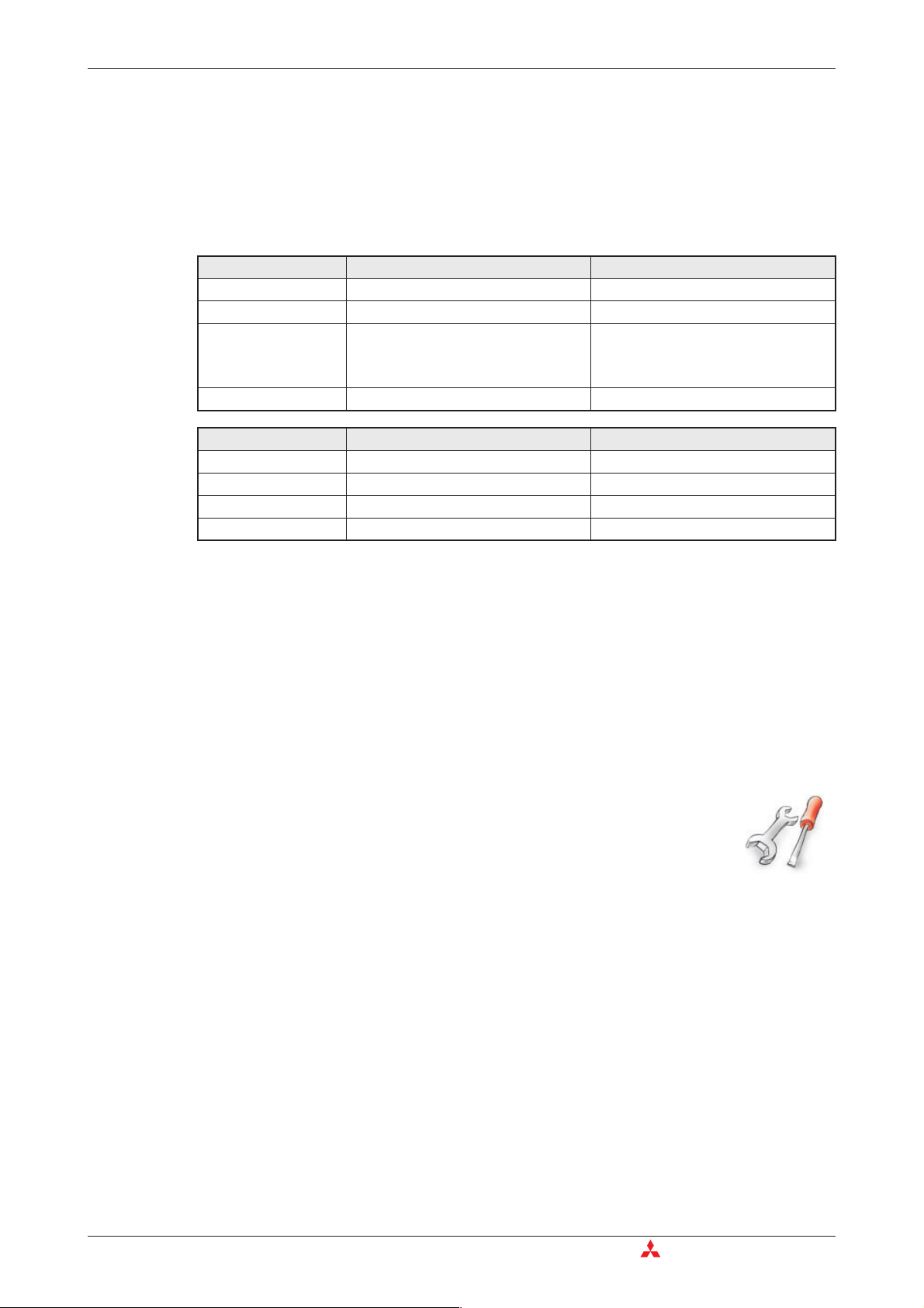
3.1.1 Interfaces and Connectors
us GSM
t
Sta
Fig. 3-1: Overview of all connectors of the Normal Modem GSM
Nr. Description Meaning
Antenna
10...40VDC Power supply (2 screw terminals) and power supply jack
LEDs 2 LEDs (Power and Line)
SIM-Karte Power supply (2 screw terminals)
RS232 Interface 9 pin D-Sub jack
Plug (FME) for Antenna cable (impendance: 50 Ω)
Tab. 3-2: Description of the connectors of the modems
NOTE For connecting the modem to a PC, a 1:1 serial standard cable is to be used. For information
to connect a PLC, refer to the PLC documentation.
Mitsubishi Industrial Modem 3-3
Page 14
Normal Modem GSM (MIM-G01) Mounting and Installation
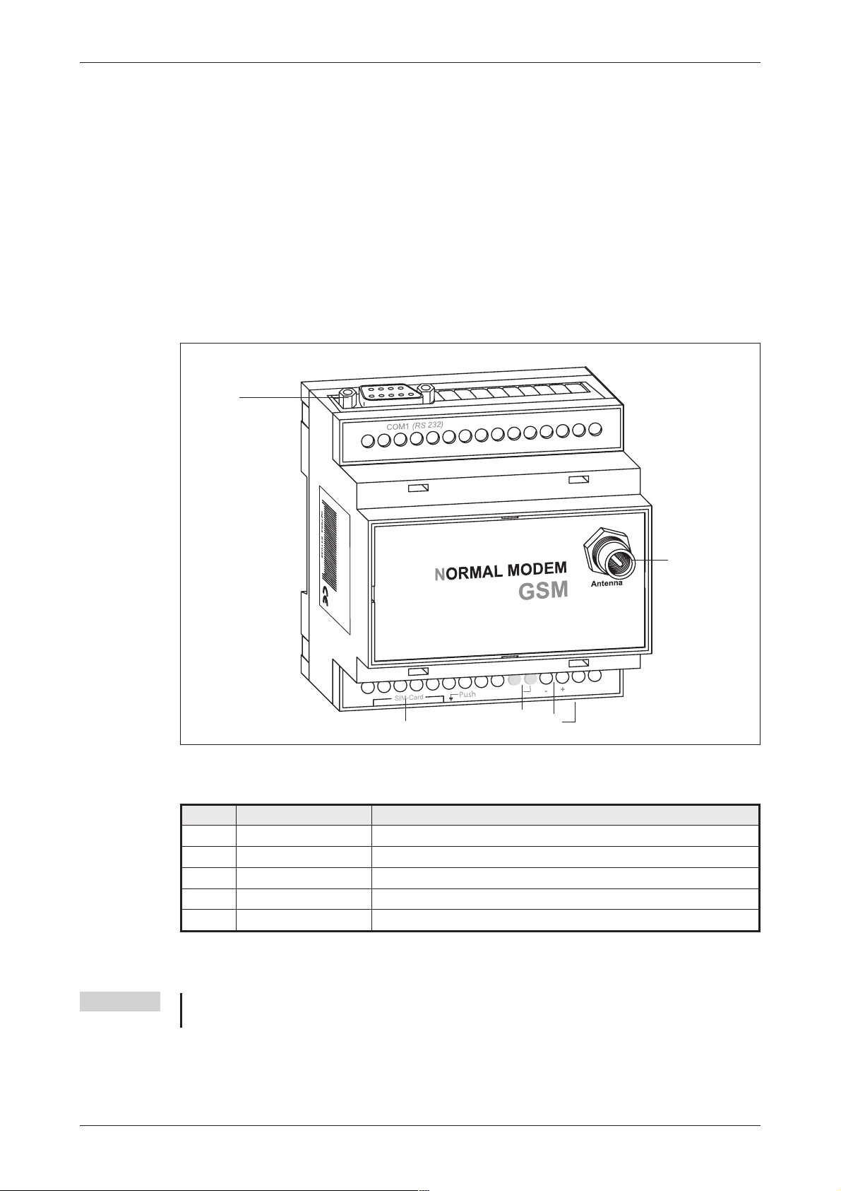
3.1.2 Meaning of the LEDs
The MIM-G01 presents two LEDs, which indicate the devices current operating mode. After the
power supply has been switched on, a self test will be executed. The end of this test is indicated
by a acoustic signal (short beep). After the test, thedevice tries to make a connection to the GSM
network. The green LED will flash slowly when the log in was successful.
COM1 (RS 232)
N
ORMAL MODEM
GSM
Antenna
Power
10...40 V DC
SIM-Card Push
Status GSM
-+
SIM-Card Push
Power
Status GSM
10...40 V DC
Fig. 3-2: LEDs on the MIM-G01
LED Status Meaning
Power
(yellow)
Off Device is switched off (power supply disabled
On Device is switched on(power supply enabled)
On Device is not logged onto the GSM network
Status GSM
(green)
Slowly flashing Device is logged onto the GSM network
Rapidly flashing
Device is logged onto the GSM network, and active connection is
established
Tab. 3-3: Two LEDs are used to show the state of the modem
-+
3-4 MITSUBISHI ELECTRIC
Page 15
Mounting and Installation Normal Modem GSM (MIM-G01)
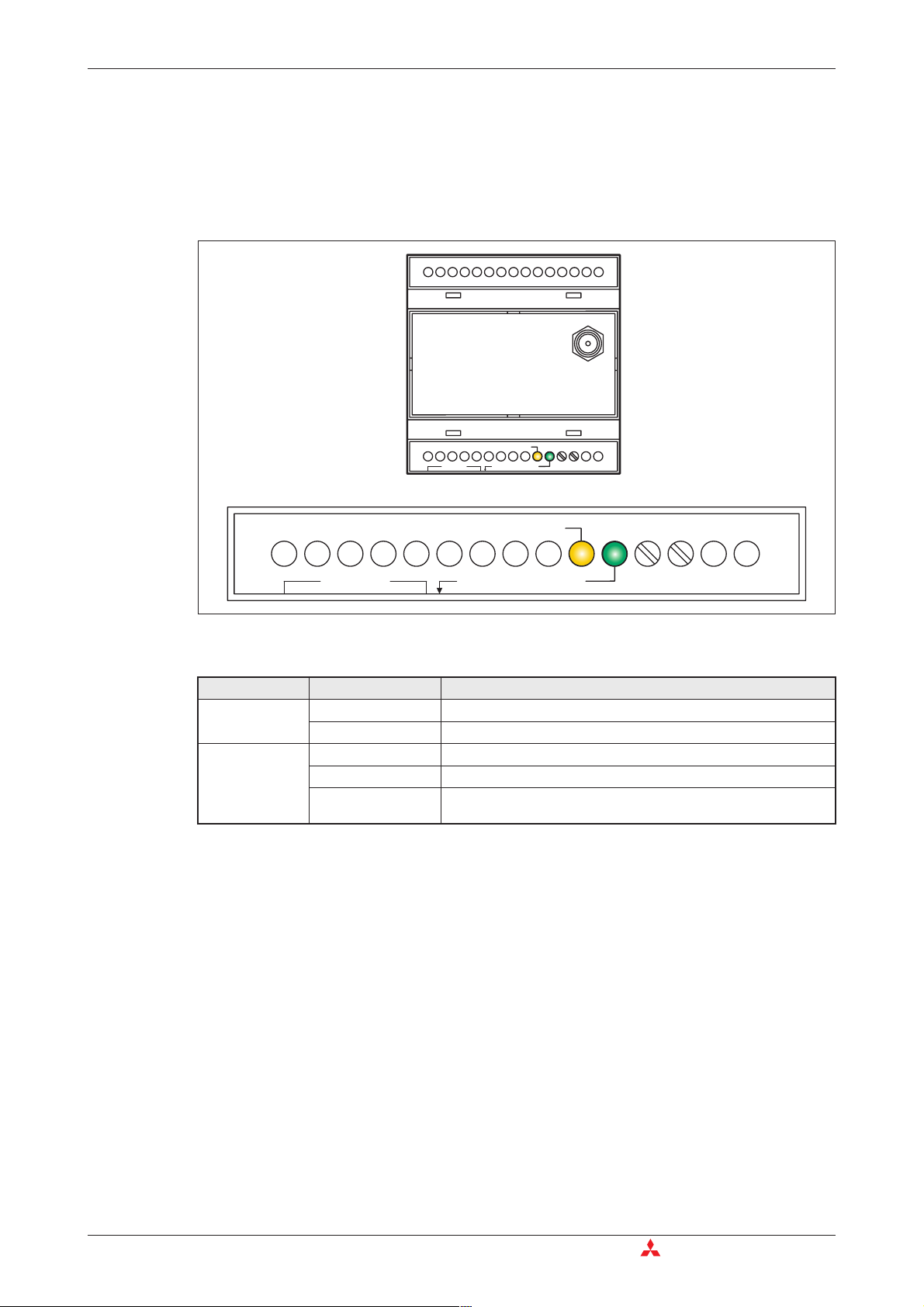
3.1.3 Connecting the GSM antenna
First of allfind a suitable location for mountingthe GSM antenna outside of thecontrol cabinet.
Screw the antenna plug into the antenna socket on the front of the modem.
Fig. 3-4:
When fitting the antenna plug ensure
that it is seated correctly. It should be
possible to turn the threaded nut easily.
usGSM
t
Sta
NOTES Standard GSM antennas with an FME plug can be used. The GSM antenna is not supplied
with the modem and can be ordered separately.
If the length of the antenna cable is not sufficient for your requirements you can use a suit
able extension cable purchased as an accessory from a GSM outlet. Take into account the
attenuation of these cables that will reduce the antenna gainand observethe relevant specifications of the manufacturer.
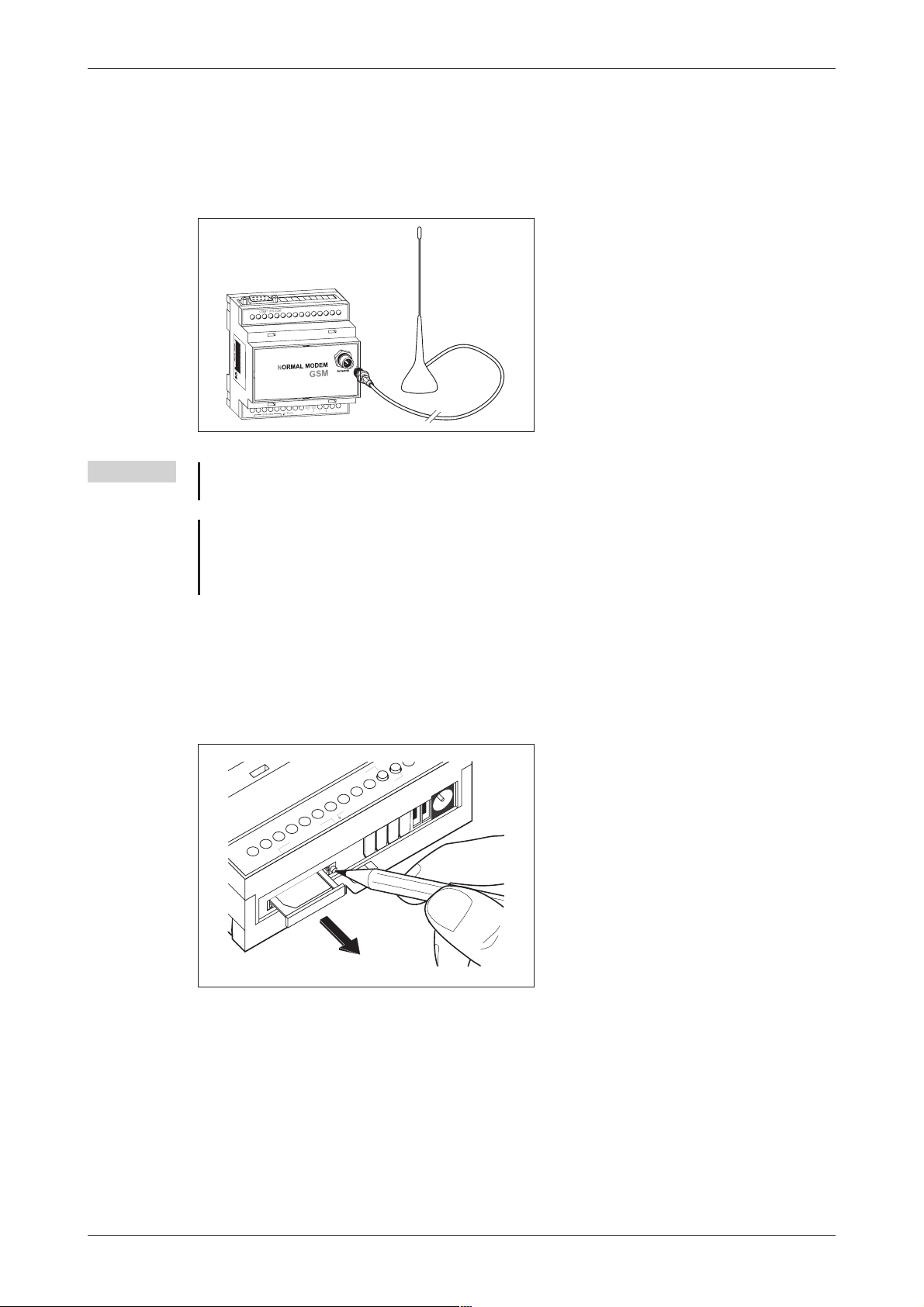
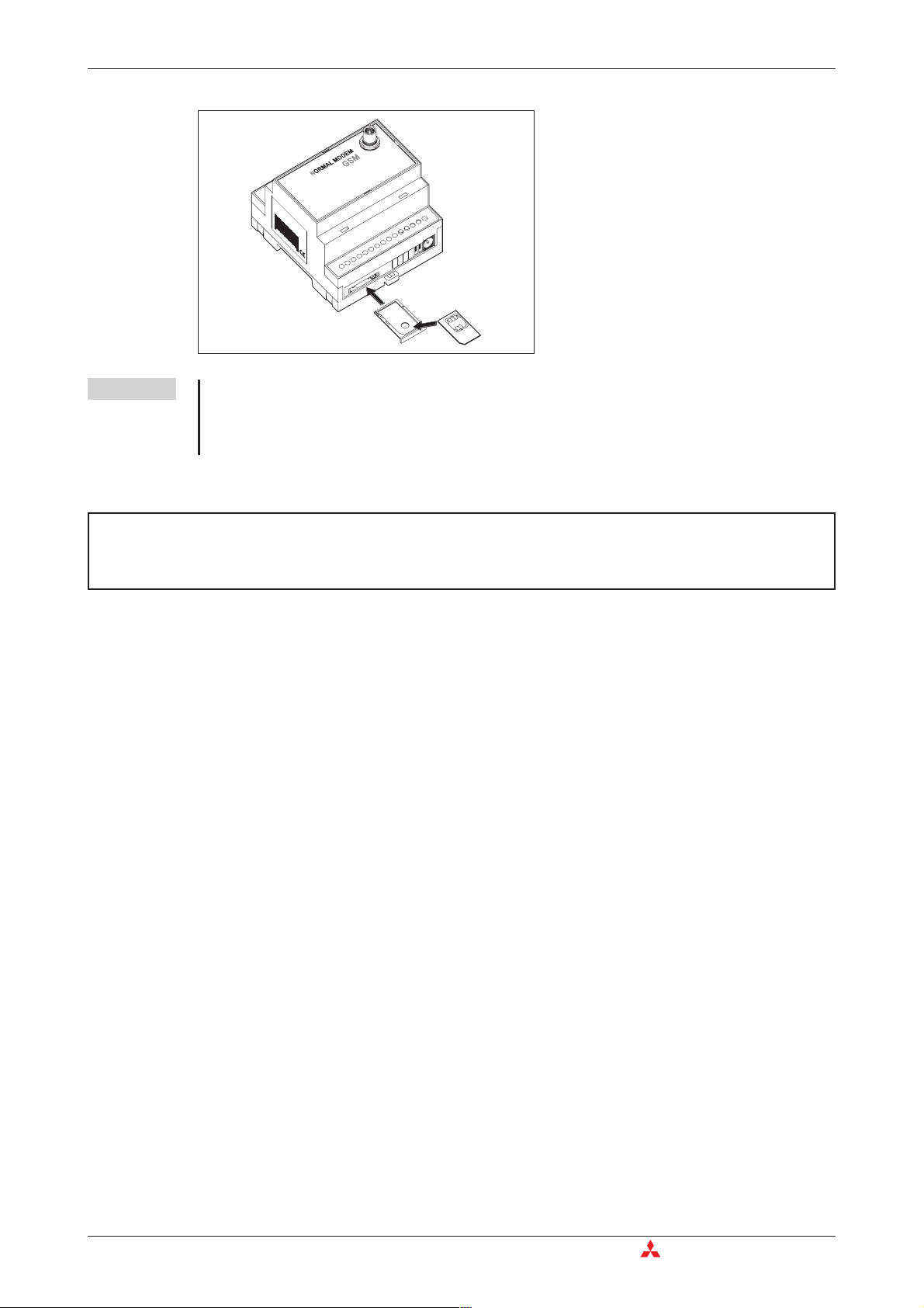
3.1.4 Inserting the SIM card
The SIM card of an mobile phone provider is necessary for the use of a GSM Modem.
To insert the SIM card in the modem, open the SIM card holder on the Mitsubishi Alarm Modem
by pressing the small button on the right of the holder with a pen or a pointed object.
Power
Status GSM
h
Pus
SIM-Card
-
-
Fig. 3-3:
Push down the button until the card
holder is released
You can now carefully pull out the card holder and insert your SIM card. Then push the SIM card
holder back into the modem until it snaps into position.
Mitsubishi Industrial Modem 3-5
Page 16
Normal Modem GSM (MIM-G01) Mounting and Installation
Fig. 3-5:
Insert the SIM card with the contact side
Antenna
facing upwards and ensure that the card
is seated correctly in the recess.
Then push the SIM card holder back into
the modem until it snaps into position.
027954 541034
10...40V DC
+
-
Power
StatusGSM
h
Pus
SIM-Card
SIM-Card
NOTE If you plan to dial into your PLC via GSM, you will possibly need a SIM card and account with
data service enabled. However, in some cases the modem may be capable of accepting
data calls ona voice number after using the AT+CICB=0command.Fordetailed information,
contact your mobile service provider.
E
ATTENTION:
The SIM card should only be removed when the modem is in power-off state.
The SIM card may become unusable if this warning is not observed.
3-6 MITSUBISHI ELECTRIC
Page 17
Mounting and Installation Super Modem 56k (MIM-A01)
3.2 Super Modem 56k (MIM-A01)
The MIM-A01 is a PSTN modem intended for transmission of data, SMS, e-mail and fax mes
sages by analog telephone networks and complies to the high speed standard of V.90 and 56k.
It is suitable for DIN-Rail mounting inside control boxes.
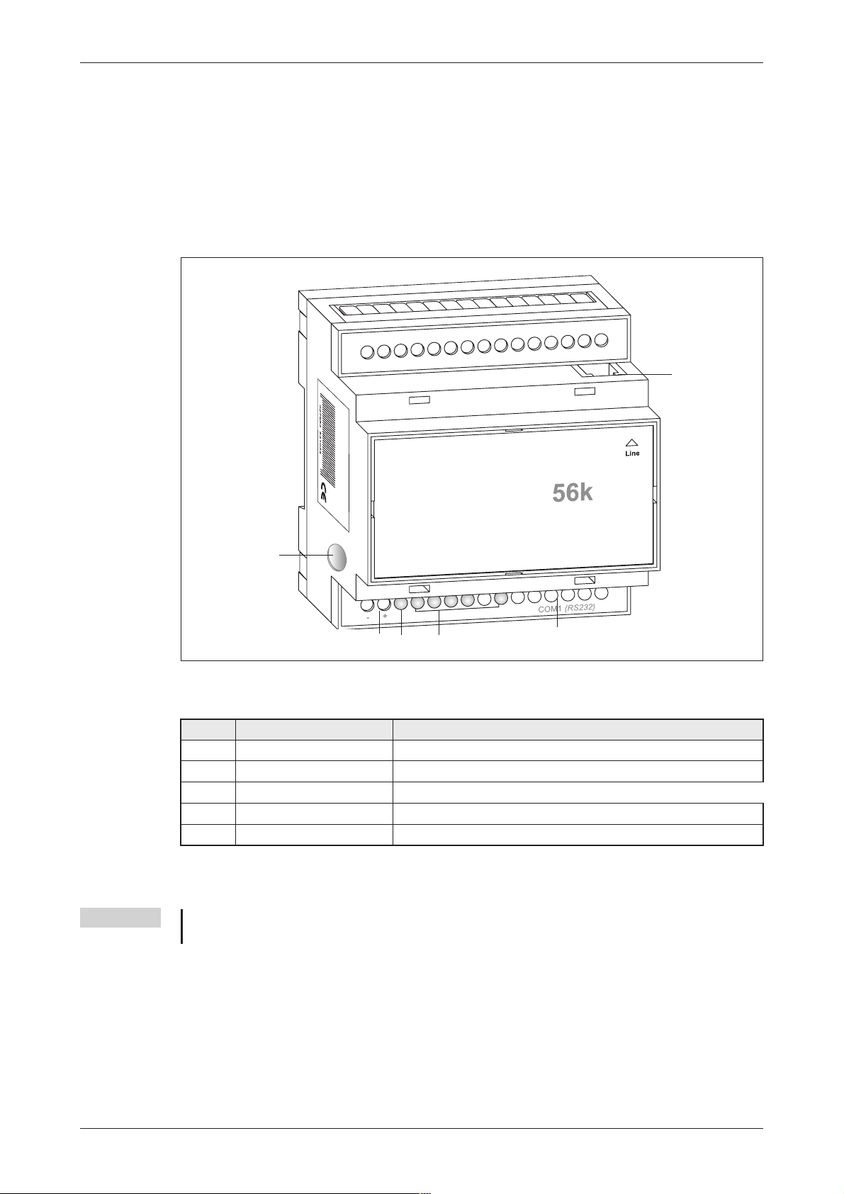
3.2.1 Interfaces and Connectors
SUPER M
DEM
O
-
Line
Power
Fig. 3-6: Overview of all connectors of the Super Modems 56k
Nr. Description Meaning
Line Telephone jack RJ11
10...30VDC Power supply (2 screw terminals) and power supply jack
Service Button
LEDs LEDs (Power, Mail in, Line, Mail out und Modem Mode)
RS232 Interface 9pin D-Sub jack
Tab. 3-4: Description of the connectors of the Modems
NOTE For connecting the modem to a PC, a 1:1 serial standard cable is to be used.For information
to connect a PLC, refer to the PLC documentation.
Mitsubishi Industrial Modem 3-7
Page 18
Super Modem 56k (MIM-A01) Mounting and Installation
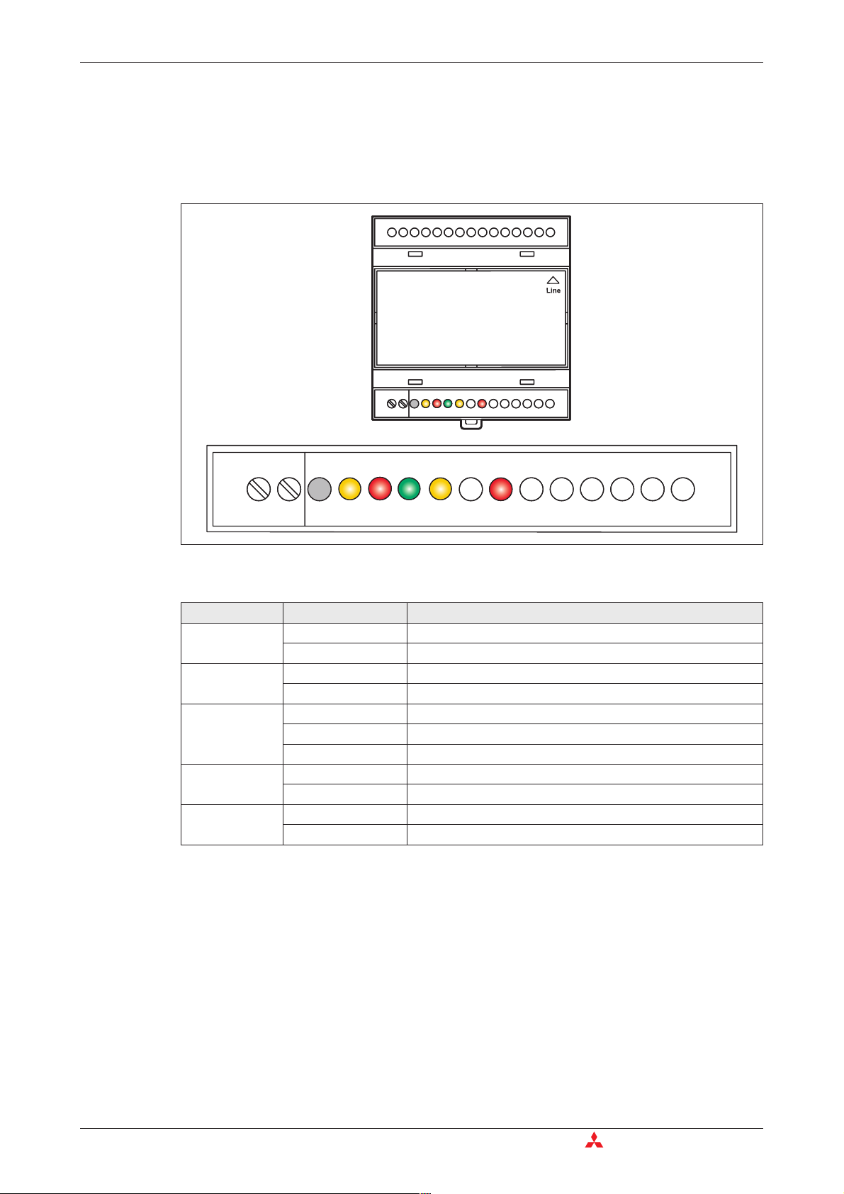
3.2.2 Meaning of the LEDs
The MIM-A01 got five LEDs, which display the modems operating status. Afterthe power supply
has been switched on, a self test will be executed. The end of this test is indicated by a acoustic
signal (short beep).
SUPER MODEM
SUPER MODEM
Service
Service
DC 10...30V
DC 10...30V
-+
-+
Power
Mail in
Mail in
Line
Line
56k
56k
Mail out Modem Mode
Mail out Modem Mode
COM1
COM1
(RS232)
(RS232)
Mail out Modem Mode
DC 10...30V
DC 10...30V
-+
-+
Service
Service
Power
Mail in
Mail in
Mail out Modem Mode
Line
Line
COM1
COM1
Fig. 3-7: LEDs on the MIM-A01
LED Status Meaning
Power
(yellow)
Mail in
(red)
Off No power supply, device switched off
On Power supply active, device switched on
Off No received message in memory
On Received message in memory
Off No telephone connection active
Line
(green)
Flashes Telephone connection becomes established
On Telephone connection successfully established
Mail out
(yellow)
Modem Mode
(red)
Off No outgoing messages in memory
On Outgoing messages in memory
Off Device is in Message Mode
On Device is in Modem Mode
Tab. 3-5: Five LEDs are used to show the state of the modem
(RS232)
(RS232)
3-8 MITSUBISHI ELECTRIC
Page 19

Mounting and Installation Super Modem 56k (MIM-A01)
3.2.3 Connection to the Telephone Network
Connection to telephone network (PSTN) is established via the included telephone cable and
the "Line" jack of the MAM.
1-b2
2-W
3-a
4-b
123456
5-E
6-a2
Fig. 3-8
The Mitsubishi Super
Modem 56k supports the
a/b leads (3 and 4).
To get access to your Mitsubishi Super Modem 56k, the telephone number of the connection
used must be known.
3.2.4 Testing the Telephone Connection
In order to check the telephone number of the connection used, plug an usual telephone into the
appropriate socket and dial the number by another telephone, or from a mobile. If the telephone
at the appropriate socket rings, the number is correct.
In order tocheck if thetelephone connection supports the CLIP feature,dial from theappropriate
connection to another telephone. If the calling number is shown atthe called party end, the CLIP
feature is supported.
If calls were successful in both directions, you can connect your Mitsubishi Super Modem. The
modem is now ready to be called and receive messages.
3.2.5 Telephone Exchange System
When connecting to a telephone exchange (PABX), take care if an outside line prefix is necessary.
Mitsubishi Industrial Modem 3-9
Page 20

Mounting Mounting and Installation
3.3 Mounting
Mount the modem by pushing or snap fitting it onto a DIN rail (top-hat rail 35 mm).
Fig. 3-9:
Pull out the black tab on the device using
a screwdriver and so the device can
snap fit to the DIN rail. You can remove
thedevicefromtherailinthesameway.
Ensure that the retaining mechanism of
the modem snaps cleanly and securely
into the DIN rail.
Fig. 3-10:
Modem mounted on the DIN rail
027954541034
Antenna
10...40V DC
+
-
Power
StatusGSM
Push
SIM-Card
E
P
ATTENTION
쎲
The device must only be used in rooms that are dry and clean. Protect the devi-
:
ce from humidity, water splashes or heat.
쎲
Do not subject the device to severe vibration.
DANGER:
쎲
The device must not be used in environments containing flammable gases,
fumes or dust.
3-10 MITSUBISHI ELECTRIC
Page 21

Power supply
4 Power supply
After all installation steps are completed, switch on the power supply to the Mitsubishi Alarm
Modem. The modem got two power supply connectors: Two screw terminals and a power sup
ply jack (pin diameter 2,1 mm, inner diameter 6 mm).
ATTENTION:
Power U = 10 – 40V DC! for Mitsubishi Normal Modem (MIM-G01)
E
NOTE In order to avoid the interference from power supply units or other interference sources,
Power U = 10 – 30V DC! for Mitsubishi Super Modem (MIM-A01)
Ensure the correct polarity of the power supply terminals.
DC cables should not be installed in the direct vicinity of AC cables.
-
P
DANGER:
쎲
Use leads with sufficient diameter only.
쎲
Do not use flexible leads with soldered tips.
쎲
Watch the polarity and the specification of the power supply.
(MIM-G01=10 – 40VDC, max. 0.7 A, Power supply jack: pin = positive)
(MIM-A01=10 – 30VDC, max. 0.7 A, Power supply jack: pin = positive)
쎲
In order to avoid damages, fasten the terminal screws with a torque momentum
of 0.5 ... 0.6Nm.
쎲
When using the power supply jack, make sure the plug got an
pin diameter of 2.1mm and inner diameter of 6mm.
쎲
Wiring must be done with power off only.
Mitsubishi Industrial Modem 4-1
Page 22

MIM-G01 Operation
5 Operation
If you have followed the steps in the chapters 3 and 4, your modem is ready for operation.
5.1 MIM-G01
The MIM-G01 presents two LEDs, which indicate the devices current operating mode. After the
power supply has been switched on, a self test will be executed. The end of this test is indicated
by a acoustic signal (short beep). After the test, thedevice tries to make a connection to the GSM
network. The green LED will flash slowly when the log in was successful..
5.2 MIM-A01
The MIM-A01 presents five LEDs, which indicate the devices current operating mode. After the
power supply has been switched on, a self test will be executed. The end of this test is indicated
by a acoustic signal (short beep).
Mail in
DC 10...30V
DC 10...30V
-+
-+
Service
Service
Mail in
Power
Fig. 5-1: LEDs on MIM-A01
Power
(yellow)
Mail in
(red)
Line
(green)
SUPER MODEM
SUPER MODEM
Mail out Modem Mode
Mail out Modem Mode
Mail in
Mail in
Service
Service
DC 10...30V
DC 10...30V
-+
-+
Power
Line
Line
Mail out Modem Mode
Mail out Modem Mode
Line
Line
Mail out
(yellow)
Flashes
56k
56k
COM1
(RS232)
COM1
(RS232)
Modem Mode
(red)
COM1
(RS232)
COM1
(RS232)
Starting self test
Testing LEDs
Testing memory
Modem is fully operational
Duration: approx. 12 sec
Tab. 5-1: LEDs during the self-test
5-1 MITSUBISHI ELECTRIC
Page 23

Configuration MIM and Mitsubishi ALPHA XL
6 Configuration
6.1 MIM and Mitsubishi ALPHA XL
Configuration of the Industrial Modems is done via the Mitsubishi Alpha Programming Software
(SW0D5-ALVLS-EUL). Detailed information on selecting the modem and setting parameters is to
be found within the Mitsubishi Alpha XL manuals at
Alpha XL - Communication Manual Art. No. 146564
Alpha Software - Software Manual Art. No. 126017
This AT init string is to be used when connecting an "Alpha XL" to the "MIM-G01":
ATE0S0=2&S0;+IFC=0,0;+CMEE=1;+IPR=9600;+CICB=0;&W
This AT init string is to be used when connecting an "Alpha XL" to the "MIM-A01":
ATE0S0=2Q1+D0\Q0\J0&W
The following chapters will show the most important settings.
http://www.mitsubishi-automation.com
6.1.1 Project Settings
Load the PLC project into the Alpha Programming Software and adjust some basic settings.
Therefore, in the menu bar click
Options > GSM and serial communication
In the area Modem, select either GSM (for MIM-G01) or Modem (MIM-A01) and choose the
name of the modem in use from the list provided on the right (see figure above).
Fig. 6-1:
GSM and serial communication
NOTE If this modem type is not present within the list, you may add it by yourself; detailed informa
tion on that is to be found within chapter 6.1.3.
If you use a MIM-A01 Modem, click on OK to exit configuration.
If you use a MIM-G01 Modem, enter the SIM PIN into the appropriate input field and enable the
„Remote Access“ checkbox, in case you want to remotely access the PLC. The Data format
should be 8bits, no parityand 1 stop bit (8N1) witha speed of9600 baud. Clickon OK toexit con
figuration.
Mitsubishi Industrial Modem 6-1
-
-
Page 24

MIM and Mitsubishi ALPHA XL Configuration
6.1.2 Function Block SMS send
For sending SMS, add a function block GSM/SMS is to be added to your PLC project.
(Detailed information is to be found within the Alpha XL Communication manual.)
Double-click the GSM function block in order to configure it.
In the window that opens, click Setting and enter these data:
Fig. 6-3:
GSM SMS (Short Message Service)
Now enter the following data:
Fig. 6-2:
SMS Setting
SMS Service Center:
Enter the SMSC number within the upper field; this number may be obtained from your service
provider. If you want to send e-mail as well, enterthe e-mail gateway number of your service pro
vider, too.
-
6-2 MITSUBISHI ELECTRIC
Page 25

Configuration MIM and Mitsubishi ALPHA XL
Recipient:
Enter several recipients with name and number here. Enable the Mobile Phone button for SMS
and Gateway for e-mail.
Click on OK to return to the previous menu. Select one of the recipients here.
Fig. 6-4:
GSM SMS (Short Message Service)
NOTE
If you selected Gateway instead of Mobile Phone, you may enter an e-mail address for this
user. Note that the appropriate number must be provided at the Gateway entry field with
SMS preferences.
Click on OK to finish the configuration of the GSM function block.
Mitsubishi Industrial Modem 6-3
Page 26

MIM and Mitsubishi ALPHA XL Configuration
6.1.3 PLC Connection
Connect the RS232 jack to the ALPHA XL, using the GSM-CAB. If done so, plug the power
supply into the appropriate terminal.
NOTE Make sure the SIM card is inserted correctly and power on both the devices.In case the PIN
is set correctly, the MIM-G01 will connect to the PLC and logs onto the GSM network.
The Modem is now ready to send messages. As soon as a GSM feature of the PLC project is
activated, the Modem dials into the SMSC provided and sends the display content as SMS.
(Detailed information is to be found within the Mitsubishi Communication manual.)
In case the modem type does not exist in the selection list of the GSM and serial communica
tion of the SW0D5-ALVLS-EUL software, it must be added manually.
Therefore select New as modem type. Then click on Initialize Modem... and within the next
dialog, enter this string for modem init:
MIM-G01
ATE0S0=2&S0;+IFC=0,0;+CMEE=1;+IPR=9600;+CICB=0;&W
MIM-A01
ATE0S0=2Q1+D0\Q0\J0&W
Fig. 6-5:
Initialisation of a GSM Modem
NOTE The entered initialize command may not be displayed in full length in the input area.
-
Click on OKto return tothe previous dialogueand continue configuration,as described in6.1.1.
6-4 MITSUBISHI ELECTRIC
Page 27

Configuration MIM and Mitsubishi MELSEC FX
6.2 MIM and Mitsubishi MELSEC FX
The modem may be operated along with MELSEC FX in two ways: As GSM modem for "FX
Messenger" or as modem for FX remote access.
6.2.1 MIM-G01 and FX Messenger
In order to connect the MIM-G01 to a FX1S Messenger, the modem must be initialized with the
following init string, which sets the handshake mode (no handshake will be executed) and the
transmission speed (19200 bps).
MIM-G01
AT+IFC=0,0;+IPR=19200;&W
The modem is to be connected to the RS232-BD of the FX Messenger via standard RS232
cable. Detailed information on configuring the FX messenger is to be found in the FX Messenger
Manual.
6.2.2 MIM for FX Remote Access
Detailed information on correct modem selection and the necessary parameters are to be found
within the Mitsubishi Manuals at http://www.mitsubishi-automation.com
GX IEC Developer – Reference Manua Art. No. 043596
FX Communications User Manual Art. No. 070143
GX Developer – Operating Manual Art. No. 160262
When using FX along with MIM-G01, we do recommend this init string:
AT+WRST=1,"024:03";+IPR=9600;+IFC=0,0;+ICF=5,1;E1V1Q1S0=2&W
The init string recommended for using the FX along with the MIM-A01, is as follows:
AT%C0"H0E0Q1V1S0=2&D0+K0&W+TFORMAT="7E1";+TBAOD="9600"
6.3 Connection to other Mitsubishi Products
The Industrie-Modems may be used along with the A and Q series of Mitsubishi PLCs, as well as
for accessing E-Terminals.
Detailed information on correct modem selection and the necessary parameters are to be found
within the Mitsubishi Manuals at
E-Terminal manuals at
http://www.e-terminals.com.
http://www.mitsubishi-automation.com
as well as well as in the
Mitsubishi Industrial Modem 6-5
Page 28

RS 232-Transparent-Mode (TransMode) Configuration
6.4 RS 232-Transparent-Mode (TransMode)
The section is only valid for the Mitsubishi Super Modem (MIM-A01).
The TransMode allows the remote control of a control unit (PLC) or another RS-232 device via a
Mitsubishi Super Modem as if you weresitting near thedevice and connected locally via RS 232.
All commands that you can give to this device via the local RS 232 interface can also be issued
via TransMode from any telephone connection or via GSM modem.
Dial-in access can be password-protected.
An application of the TransMode command, for example, would be the control and configuration
of a technicalsystem that isconnected to theMitsubishi Super Modemvia an RS232 interface.
To use the TransMode, do the following:
햲
Configure the Mitsubishi Super Modem using the TransMode command
햳
Connect your Mitsubishi Super Modem to the device you want to control remotely.
To do so youwill need anull modem cable (usually plug-plug),for example, the "Blue Adapter".
햴
Test the remote dial-in with a Mitsubishi Super Modem or another modem using a
terminal program (dial-in of the Mitsubishi Super Modem).
햵
The Login command for the selected Mitsubishi Super Modem must be entered
within 5 seconds
nected to both modems.
햶
Control your remote device.
All data that you send from the PC to the local modem is transmitted over the telephone line to
the Mitsubishi Super Modem AT and from this modem to the connected device via RS 232.
You can operate the connected device as if you were directly sitting in front of it.
햷
Close the connection by
– hanging up by the caller modem
– optional timeout in the Mitsubishi Super Modem when no
more data is coming (default: 75 seconds)
of the modem connecting (see section 6.4.3). The RS 232 is then con
-
6.4.1 Time delays during modem transmissions
A remote connection and data conversion in both modems lead to delays in the runtime of data
from PC to the control unit in comparison to a direct local connection via an RS 232 cable. Some
configuration programs for control units expect a response within a few milliseconds. Errors can
occur in these programs. Ask the manufacturer of these programs and control units how the
timeout for thecommunication with the control unit canbe increased to,for example, 500ms.
6-6 MITSUBISHI ELECTRIC
Page 29

Configuration RS 232-Transparent-Mode (TransMode)
6.4.2 TransMode Command
AT+T SEND="TransMode; ..."
AT+T SEND="TransMode; Enabled:Enabled;Password: Password; Format: Format;
Handshake:Handshake; Keep:timeout; Baudrate: RS232Speed;
Com:Port"
Switches the RS 232 to a connected device during dial-in from the outside
so that the device can be controlled remotely.
Enabled
Password
format
handshake
timeout
RS232Speed
Port
Example:
AT+T SEND="TransMode; Password:sesam; Format:8N1; Handshake:None;
Keep:20; Baudrate:9600; Enabled:On; Com:MB"
When a call is being received, the Tixi modem connects the RS 232 to the connected device.
All data is now transmitted in both directions as if the devices were connected directly.
Sets theTransMode to active (On) or inactive (Off).
Access password
This protects your Mitsubishi Super Modem AT from unauthorized dial-in
and thus protects the connected control unit from being used by unauthori
zed persons.
When no password isindicated (default: empty) andAT+T Answer="On",
anything can be selected.
Data format of the RS232 interface.
Notation: DatabitsParityStopbits. Default: 8N1.
Handshake protocol for the RS 232.
Values: None, RTSCTS, XONXOFF
Idle timeout - Sets how long the connection remains available in case no
more data is transmitted.
The default value is 75 seconds.
A value of 0 switches this function off, that is, the Mitsubishi Super Modem
will not end the connection even if no more data is coming
Data speed on the RS 232
between the Mitsubishi Super Modem and device connected to it.
Default value: 115,200 Baud.
Remote interface to connect to.
The Mitsubishi Super Modem is configured for the TransMode:
-
6.4.3 TransMode Login Command
To use the TransMode of the Mitsubishi Super Modem, these prerequisites must be met
쎲
The Mitsubishi Super Modem must be connected to a working telephone connection.That
means you must be able to call it. (check first using a telephone)
쎲
Call answering on the Mitsubishi Super Modem must be activated
(AT+T Answer="On").
쎲
The Mitsubishi Super Modem must first be configured using the TransMode command.
For access to a PLC connected to a Mitsubishi Super Modem a log in to the Mitsubishi Super
Mode via a modem connection is required. Use a Mitsubishi Super Modem or any other modem
for this purpose.
Send the login command for the TransMode command at the latest five seconds after CON
NECTING.
There are two possibilities for the login command, which are described as follows.
-
Mitsubishi Industrial Modem 6-7
Page 30

RS 232-Transparent-Mode (TransMode) Configuration
Login without parameters
[password] Login with password
[ ] Login without password
Login with password and parameters
[password; Format:format; Handshake:handshake; Keep:timeout; Baudrate:
RS232Speed]
For a description of the parameters, see Section 6.4.2
The configuration of the Mitsubishi Super Modem should be done locally during set-up, tested
and only then approved for remote dial-in.
The remote modification of the parameters overwrites the previously configured – and tested parameters
The remote modification of the parameters should only be used if it is absolutely necessary.
It can also be used to exclude possible local modifications.
6-8 MITSUBISHI ELECTRIC
Page 31

Technical Data
7 Technical Data
Main Features
Features MIM-G01 MIM-A01
Fax Via Fax-to-Fax-Gateway Send text messages to fax machines
SMS
E-Mail Via SMS-to-E-Mail-Gateway Send and receive E-Mail (SMTP/POP3)
Express-E-Mail —
Remote Control —
Tab. 7-1: Main Features
System Architecture
Send and receive SMS
(GSM and GPRS Mode)
Send and receive SMS
Send and receive E-Mail via secure tele
phone connection, with immediate
delivery and without internet
Remotely control your PLC via a telephone
connection
-
Features MIM-G01 MIM-A01
CPU — 32 Bit RISC-processor
Program Memory — Max 1 MB Flash-ROM
Data Memory — 30...100 kB SRAM
Tab. 7-2: System Architecture
Telephone- /GSM Network
Features MIM-G01 MIM-A01
Network GSM/GPRS, Dual Band, 900/1800 MHz Analog telephone line jack (a/b interface), RJ11
GPRS- Features
GSM Features
Antenna Jack
Data Transmission
Fax Transmission
Error Correction/
Data Compression
GPRS multi slot Class 10, GPRS mobile
station Class B, Coding Schemes CS1, 2,
3, 4, complies to SMG31bis
Call Forwarding, Call Barring, Multiparty, Call
Waiting, Call Hold, Calling Line Identity, Advice
of Charge, USSD, Close User Group
FME (male), Coaxial, Impedance 50 Ω,
Rec.Freq. 925...960 MHz
1805...1880 MHz
SendingFreq. 880...915 MHz
1710...1785 MHz
Capacity 2 W at 900 MHz
1 W at 1800 MHz
300 – 14,4 kbps async., transparent / not
transparent, ITU-T (V.21, V.22, V.22bis,
V.26ter, V.32, V.34, V110)
Fax Group 3 / Class 1 and 2.
2400 bps – 14,4 kbps ITU-T (V.17, V.29, V.27ter)
Data Compression: MNP2, V.42bis
MNP", V.42bis V.42 / MNP 2-4, V.42bis / MNP5
—
—
—
300bps - 56kbps
ITU-T (V.90, V.34+, V.32bis, V.32, V.22bis,
V.22, V.21), Bell 212A, Bell103
Fax Group 3 / Class 1
2400bps - 14,4kbps, ITU-T
(V.17, V.29, V.27ter, V.21 ch2)
Tab. 7-3: Telephone- /GSM Network
Mitsubishi Industrial Modem 7-1
Page 32

Technical Data
Firmware
Features MIM-G01 MIM-A01
Operating System —
File System —
Commercial RTOS (real-time multitasking
operating system) with C++ abstraction
layer
Commercial DOS-compliant flash file sys
tem with C++ abstraction layer
Tab. 7-4: Firmware
General Data
Features MIM-G01 MIM-A01
Power Supply 10...40VDC, max. 0.7A (2-pin screw termi
nal 2.5mm²) and jack (pin diameter =
2.1mm, inner diameter = 6mm)
LED Signals Power and Status GSM Power, Mail in, Line, Mail out, Modem
Controls — Service-Button
Allowed Temperature Operation: 0...+50°C, Storage: -30...+70°C
Allowed Humidity 5...95% relative humidity, non-condensing
Protection Level IP20
Soiling Protection 2
RS 232 RS 232 nach ITU-T V24, V28, Hardware Handshake
Baudrate: 300 – 115.200 bps, 300 – 115.200 bps wiht Autobauding
9-pin D-Sub Jack (female)
Signal line Pin Signal line Pin
TX CT103 3 DSR CT107 6
RX CT104 2 DTR CT108-2 4
RTS CT105 7 DCD CT109 1
CTS CT106 8 RI CT125 9
GND CT102 5
Conformity Standards: , EN55022 (9:2003),
EN55024 (10:2003) EN301489-1/7 (2000 GSM)
EN60950
3GPP TS 51.010-1 (9:2002, v5.0.0.0)
GCF-CC (10:2002, v3.8.1)
Extra Features Software upgrade,
Voice and DTMF Capable
Case/Mounting DIN-Rail 35mm (EN50022), vertically or horizontally
Dimensions Width: 88mm x Height: 58mm x Depth: 91mm (without antenna connection)
Weight 190 g 180 g
10...30VDC, max 0.7A, screw terminals
-
2
2.5mm
(pin diameter = 2.1mm,
inner diameter = 6mm)
Mode
Standards: , EN55022 (9:2003),
EN55024 (10:2003)
EN60950
R&TTE policy TS 103021
Software upgrade,
Voice and DTMF Capable
and power supply jack
-
Tab. 7-5: General Data
7-2 MITSUBISHI ELECTRIC
Page 33

Technical Data Dimensions
7.1 Dimensions
7.1.1 MIM-G01
88
RS 232
N
ORMAL MODEM
GSM
Antenna
SIM-Card Push
91
Push
Power
Status GSM
10...40 V DC
71
58 13
NORMAL MODEM GSM
with 1x Rs232
4 027954
541034
10 - 40VDC, max. 0.7 A
-+
4
6
4,3
Fig. 7-1: Dimensions
Mitsubishi Industrial Modem 7-3
Page 34

Dimensions Technical Data
7.1.2 MIM-A01
88
SUPER MODEM
56k
DC 10...30V
-+
91
Service
Power
Mail in
Line
4 027954
541034
Mail out
Modem Mode
58
10 - 30VDC, max. 0.7 A
SUPER MODEM 56k
with 1x RS232
COM1
(RS232)
46
4,3
Fig. 7-2: Dimensions
7-4 MITSUBISHI ELECTRIC
Page 35

Appendix AT Commands MIM-G01
8 Appendix
8.1 AT Commands MIM-G01
This chapter describes the most important MIM-G01 AT modem commands. Detailed informa
tion on these may be obtained from
8.1.1 Important AT Commands
+CPIN – PIN
This command requests the PIN status and enters the PIN/PUK.
Command Possible answers
AT+CPIN? +CPIN: READY PIN OK or not necessary
AT+CPIN=<pin>
Note: enter PIN
AT+CPIN=<puk>,<pin>
Note: enter PUK and new PIN
Tab. 8-1: +CPIN – PIN
Defined parameters:
<pin> 4...8 digit PIN <puk> 8 digit PUK
-
www.mitsubishi-automation.de.
+CPIN: SIM PIN PIN required
+CPIN: SIM PUK PUK1 required
+CPIN: SIM PIN2 PIN2 required
+CPIN: SIM PUK2 PUK2 required
+CME ERROR: <err> SIM error
OK
OK
+CSQ – Signal Quality
This Command requests the signal quality.
Command Possible answers
AT+CSQ +CSQ: <rssi>,<ber>
OK
Note: <rssi> and <ber> see below
Tab. 8-2: +CSQ – Signal Quality
Defined parameters:
<rssi> : <ber> :
0: -113 dBm or less 0…7: RXQUAL value
1: -111 dBm 99: unknown or not recognizable
30: -109 ... -53 dBm
31: -51dBm or more
99: unknown or not recognizable
Mitsubishi Industrial Modem 8-1
Page 36

AT Commands MIM-G01 Appendix
+CNUM – Own Number
This Command sets the own number (MSISDN) of the SIM card for any service.
Command Possible answers
AT+CNUM
Note: request MSISDNs
+CNUM : <alpha1>, <number1>, <type1> <CR><LF>
+CNUM : <alpha2>, <number2>, <type2>....
Tab. 8-3: +CNUM – Own Number
Defined parameters:
<alphax> name for the number <numberx>
<numberx> number in format determined by <typex>
<typex> type of adresse-byte in integer format
Example:
+CNUM :"Phone", "0612345678",129
+CNUM :"Fax", "0687654321",129
+CSCA – SMS Center Number
This Command requests or changes the SMSC number saved on the SIM card.
Command Possible answers
AT+CSCA?
Note: request SMSC number
AT+CSCA="<number>"
Note: save Service Center number
+CMS ERROR: 330
Note: service center unknown
+CMS <number>
Note: number of SMSC
OK
Tab. 8-4: +CSCA – SMS Center Number
Defined parameters:
<number> SMSC number
+IPR – Baudrate
This Command sets baudrate of serial interface.
Command Possible answers
AT+IPR? +IPR: <rate>
OK
AT+IPR=<rate>
Note: disable autobauding and set given
baudrate.
OK
Tab. 8-5: +IPR – Baudrate
Defined parameters:
<rate> Data rate in bps (0 = Autobauding)
8-2 MITSUBISHI ELECTRIC
Page 37

Appendix AT Commands MIM-G01
+ICF–DataFormat
This Command sets data format of serial interface.
Command Possible answers
AT+ICF? +ICF: <format>,<parity>
OK
Note: current values
AT+ICF=<format>,<parity> OK
Tab. 8-6: +ICF–DataFormat
Defined parameters:
<format> <parity> <format> <parity>
1: 8 Data 2 Stop 0: Odd 4: 7 Data 2 Stop 3: Space
2: 8 Data 1 Parity 1 Stop 1: Even 5: 7 Data 1 Parity 1 Stop 4: None
3: 8 Data 1 Stop 2: Mark 6: 7 Data 1 Stop
If <format> is 1, 3, 4 or 6, <parity> will be ignored
+IFC – Flow Control
This Command determines flow control on serial interface.
Command Possible answers
AT+IFC? +IFF: <DCE_by_DTE>,<DTE_by_DCE>
OK
Note: current values
AT+IFC=<DCE_by_DTE>,<DTE_by_DCE> OK
Tab. 8-7: +IFC – Flow Control
Defined parameters:
< DCE_by_DTE > < DTE_by_DCE >
0: none 0: none
2: RTS 2: CTS
Mitsubishi Industrial Modem 8-3
Page 38

AT Commands MIM-G01 Appendix
+COPS – GSM Network
This command requests accessible networks and sets the GSM home network.
Command Possible answers
AT+COPS?
Note: request current network
AT+COPS=?
Note: request list of available networks
AT+COPS=0
Note: logon to the home network
AT+COPS=<mode>,<format>,<oper>
Note: set network
+COPS: <mode>,<format>,<oper>
OK
+COPS: (<stat>,"long <oper>","short <oper>","numeric <oper>")
OK
OK
Note: successful
OK
Note: successful
Tab. 8-8: +COPS – GSM Network
Defined parameters:
<mode> <format>:
0: automatic (standard) Format of <oper> parameters
1: manual 0: long alphanumeric format
2: logoff; device is logged off until 1: short alphanumeric format
<mode>=0 or 1 is selected. 2: numeric format (standard) and <stat>
3: writes <format> (for output with AT+COPS?) Status of <oper>
4: manual / automatic (<oper> required)
<stat> <oper>: Service Provider ID
0: unknown long alphanumeric format: 16 chars
1: available short alphanumeric format: 8 chars
2: active numeric format (standard) and <stat>: 5 chars
+CMGS – Send SMS
The Command sends SMS.
Command Possible answers
AT+CMGS= <da><CR>
text entry<Strg-Z / ESC >
+CMGS: <mr>
OK
Note: transmitted ok
Tab. 8-9: +CMGS – Send SMS
For sending the message, <Strg-Z> (ASCII 26) must be entered. The text may contain any cha
racter except <Strg-Z> and <ESC> (ASCII 27).
Defined parameters:
<da>: <mr>:
Recipient number message reference number, (will be counted up automatically)
(Ring buffer, 0-255)
-
8-4 MITSUBISHI ELECTRIC
Page 39

Appendix AT Commands MIM-G01
8.1.2 Overview of AT-Commands
Service Commands
Command Description
+CLIR Calling Line Identification (Transmission of the phone number)
+CLIP Calling Line Identification (Display of the phone number of the caller)
+COLP Connected Line Identification
+CAOC Advice Of Charge
+CACM Accumulated Call Meter
+CAMM Accumulated Call Meter Maximum
+CPUC Price Per Unit and Currency Table
+CHLD Supplementary Services
+CLCC List Current Calls
+CSSN Service Notifications
+CUSD Supplementary Service Data
+CCUG Closed User Group
Tab. 8-10: Service Commands
V24-V35 Commands
Command Description
+IPR Fixed DTE Rate
+ICF DTE-DCE Character Framing
+IFC DTE-DCE Local Flow Control
&C Set DCD Signal
&D Set DTR Signal
&S Set DSR Signal
O Back to Online Mode
Q Result Code Suppression
V DCE Response Format
Z Default Configuration
&W Save Configuration
&T Auto-Tests
E Echo
&F Restore Factory Settings
&V Display Configuration
I Request Identification Information
A/ Repeat Last Command
Tab. 8-11: V24-V35 Commands
Mitsubishi Industrial Modem 8-5
Page 40

AT Commands MIM-G01 Appendix
Dial Commands
Command Description
D Dial command
H Hang-up Command
A Answer a Call
+CEER Extended Error Report
+VTD, +VTS DTMF Signals
ATDL Redial Last Telephone Number
AT%Dn Automatic Dialing with DTR
ATSO Automatic Answer
+CICB Incoming Call Bearer
Tab. 8-12: Dial Commands
General Commands
Command Description
+CGMI Manufacturer Identification
+CGMM Request Model Identification
+CGMR Request Revision Identification
+CGSN Product Serial Number
+CSCS Select TE Character Set
+CIMI Request IMSI
+CCID Card Identification
+GCAP Capabilities List
+CPOF Power Off
+CFUN Set Phone Functionality
+CPAS Phone Activity Status
+CMEE Report Mobile Equipment Errors
+CKPD Keypad Control
+CCLK Clock management
+CALA Alarm management
Tab. 8-13: General Commands
Network
Command Description
+CSQ Signal Quality
+COPS Operator Selection
+CREG Network Registration
+WOPN Read Operator Name
+CPOL Preferred Operator List
Tab. 8-14: Network
Security
Command Description
+CPIN Enter PIN
+CPIN2 Enter PIN2
+CPINC PIN Remaining Attempt Number
+CLCK Facility Lock
+CPWD Change Password
Tab. 8-15: Security
8-6 MITSUBISHI ELECTRIC
Page 41

Appendix AT Commands MIM-G01
Phonebook
Command Description
+CPBS Select Phone Book Memory
+CPBR Read Phone Book Entries
+CPBF Find Phone Book Entries
+CPBW White Phone Book Entry
+CPBP Phone Book Phone Search
+CPBN Move Action in Phone Book
+CNUM Subscriber Number
+WAIP Avoid Phone Book Init
Tab. 8-16: Phonebook
SMS Commands
Command Description
+CSMS Select Message Service
+CNMA New Message Acknowledgement
+CPMS Preferred Message Storage
+CMGF Preferred Message Format
+CSAS Save Settings
+CRES Restore Settings
+CSDH Show Text Mode parameters
+CNMI New Message Indication
+CMGR Read Message
+CMGL List Message
+CMGS Send Message
+CMGW Write Message to Memory
+CMSS Send Message from Storage
+CSMP Set Text Mode Parameters
+CMGD Delete Message
+CSCA Service Center Address
+CSCB Select Cell Broadcast Message
+WCBM Cell Broadcast Message IDs
+WMSC Message Status Modification
+WMGO Message Overwriting
Tab. 8-17: SMS Commands
Data Commands
Command Description
+CBST Bearer Type Selection
+FCLASS Select Mode
+CR Service Reporting Control
+CRC Cellular Result Codes
+ILRR DTE-DCE Local Rate Reporting
+CRLP Radio Link Protocol Parameters
+DOPT Others Radio Link Parameters
%C Select Data Compression
+DS V42 bis Data Compression
+DR V42 bis Data Compression Report
\N Select Data Error Correcting Mode
Tab. 8-18: Data Commands
Mitsubishi Industrial Modem 8-7
Page 42

AT Commands MIM-G01 Appendix
Fax Commands CLASS1
Command Description
+FTM Transmit Speed
+FRM Receive Speed
+FTH HDLC Transmit Speed
+FRH HDLC Receive Speed
+FTS Stop Transmission and Wait
+FRS Receive Silence
Tab. 8-19: Fax Commands CLASS1
Fax Commands CLASS2
Command Description
+FDT Transmit Data
+FDR Receice Data
+FET Transmit Page Punctuation
+FPTS Page Transfer Status Parameters
+FK Terminate Session
+FBOR Page Transfer Bit Order
+FBUF Buffer Size Report
+FCQ Copy Quality Checking
+FCR Capability to Receive
+FDIS Current Sessions Parameters
+FDCC DCE Capabilities Parameters
+FLID Local ID String
+FPHCTO Page Transfer Timeout Parameter
Tab. 8-20: Fax Commands CLASS2
Special AT Commands
Command Description
+CCED Cell Environment Description
+CCED Automatic RxLev Indication
+WIND General Indications
+ADC Analog Digital Converter
+CMER Mobile Equipment Event Reporting
+WLPR Read Language Preference
+WLPW Write Language Preference
+WIOR Read GPIO Value
+WIOW Write GPIO Value
+WAC Abort Command
+WTONE Play Tone
+WDTMF Play DTMF Tone
+WDWL Wavecom Downloading
+WVR Wavecom Voice Rate
+WDR Data Rate
+WHWV Hardware Version
+WDOP Date Of Production
+WSVG Wavecom Select Voice Gain
+WSTR Wavecom Status Request
+WSCAN Wavecom Scan
+WRIM Ring Indicator Mode
+W32K Power saving mode
Tab. 8-21: Special AT Commands
8-8 MITSUBISHI ELECTRIC
Page 43

Appendix AT Commands MIM-A01
8.2 AT Commands MIM-A01
8.2.1 Overview of AT Commands
Commands can be entered alone or in strings, and they must be preceded - except the A/ com
mand - by the character sequence AT (or at) and ended with the content of theS3 register, which
usually is <CR/LF>. For example:
ATX1<CRLF>
ATQ0<CRLF>
The maximum length of a command line is 80 characters. If more commands are issued, the
modem responds with an error message. The commands can be sent with or without spaces
between commands and in upper-case or lower-case letters.The following commands produce
the same results:
ATX1QODP12345<CRLF>
At X1 Q0 Dp 12345<CRLF>
Use the Backspace key to delete errors.
In this summary and the following descriptions, the preceding AT sequence is not listed.
Command Description
A Answer mode
A/ Repeat last command
B Select ITU-T or Bell
D Dial command
E Command mode echo
H Switch hook control
I Identification/checksum option
L Speaker volume control
M Speaker control
N Select data rate handshake
O Go online
P Select pulse dialing
Q Result code display control
S Select an S register
T Select tone dialing
+TFORMAT Data format at the serial interface
+TBAUD Baud rate of the serial interface
V Result code form
W Response code data rate
X Result code type
Z Recall stored profile
+++ Escape Sequence to return temporarily to Command mode
&C DCD (data carrier detect) option
&D DTR (data terminal ready) option
&F Load factory defaults
&G Guard tone option (1200 bps and 2400 bps only)
&K Select serial port flow control
&P Dial pulse ratio
&S DSR (data set ready) option
&U Disable Trellis coding
&V View active and stored profiles
&W Store active profile
&Y Select stored profile on power-up
-
Tab. 8-22: Overview of AT Commands (1)
Mitsubishi Industrial Modem 8-9
Page 44

AT Commands MIM-A01 Appendix
Command Description
&Z Store telephone number (up to 30 digits) to location 'n' (0-3)
%E Auto-retrain control
%G Rate renegotiation
-C Generate data mode calling tone
+ES Error control selection
+MS Modulation selection
*NC CallerID settings
+VCID Country code setting
@D Accept a new firmware image to flash
Tab. 8-23: Overview of AT Commands (2)
8.2.2 AT Command Descriptions
This chapter describes the most important AT commands of the modem. The values marked
with an asterisk (*) are the default values.
+TFORMAT - Sets the data format
Sets the data format of the serial interface.
+TFORMAT="Dataformat"
Dataformat:
DatabitsParityStopbits
Databits: 8, 7
Parity: N (none), O (odd), E (even), X (auto-detection, default)
Stopbits: 1, 2
+TBAUD - Set the baudrate
Sets the baud rate of the serial interface.
+TBAUD="Baudrate"
Baudrate:
AUTO (default), 300, 1200, 2400, 4800, 9600, 19200, 38400, 57600, 115200,
230400
&K - Select Serial Port Flow Control
This command specifies the DTE-to-modem flow control. Software flow control uses the charac
ters XOFF (13h) and XON (11h) to stop and start data transmission, respectively, both to and
from the DTE. Bidirectional hardware flow control uses RTS/CTS to stop and start data from the
modem
&K0 Disables flow control
&K3* Bi-directional hardware flow control - RTS/CTS
&K4 XON/XOFF software flow control
&D - DTR (Data Terminal Ready) Option
-
This command controls how the modem responds to DTR. After toggling DTR, the host should
wait 200 ms before modifying the UART registers or sending a new command to the modem.
This is done because the modem does not send an ‘OK’ message to indicate it has performed
the requested function.
&D0 The modem ignores DTR.
&D1 The modem switches from data to command mode when an on-to-off transitionof DTR occurs.
&D2* An on-to-off transition of DTR causes the modem to go on-hook (hang up). While DTR
is off, auto-answer is disabled.
&D3 An on-to-off transition of DTRreinitializes the modem. The reinitializeprocedure performs the
same function as a power-up reset, except that the UART registers are not reconfigured.
8-10 MITSUBISHI ELECTRIC
Page 45

Appendix AT Commands MIM-A01
D - Dial Command
This command causes the modem to immediately go off-hook as an originating modem and dial
a telephone number with corresponding dial modifiers. Dialmodifiers are parameters that define
how the modem should dial the telephone number.
Dial Modifiers
0-9 Dialling Digits
A, B, C, D, *, # Tone Dial Characters
P Pulse Dial: configures the modem to use pulse dialling to dial a telephone number.
R Reverse Originate Mode: places the modem in answer mode.
This modifier should be the last character in the Dialling string (for example,
ATDT 12345678R). After dialling the telephone number, the modem goes
into data modem answer mode instead of originate mode.
S = n Dial NVRAM Telephone Number: causes the modem to dial a telephone
number previously stored in the NVRAM with the AT&Zn=x command.
T Tone Dial: configures the modem to use DTMF tones to dial a telephone number.
W Wait for Dial Tone: causes the modem to look for dial tone for a specified
amount of time. If dial tone or the amount of time specified by the S6
register times out, the modem processes the next command in the dial
string. If a busy signal is detected, the modem responds to the DTE with a
busy response code and then enters off-line command mode.
<space> - ( ) Ignored by Modem: these four characters are ignored by the modem.
Spaces also may be included in the dial string to separate area codes and
numbers.
L Dials the last number used for dialling.
E - Command Mode Echo
This command selects whether the modem echoes AT commands back to the host in either
online or off-line command mode.
E0 Echo disabled
E1* Echo enabled
H - Switch Hook Control
This command controls the telephone line relay (OHREL*) and causes the modem to either
hang up or pick up the telephone line. The H command can be issued only after the escape
sequence has been entered.
H0* Hang up telephone line (go on-hook)
H1 Pick up telephone line (go off-hook)
Q - Result Code Display Control
This command selects whether the modem sends result codes to the DTE.
Q0* Result codes enabled
Q1 Result codes disabled
X - Result Code Type
This command determines which modem result codes are enabled. Additionally, this command
specifies whether busy and dial tone detection are enabled or disabled.
X3 Result codes 0-5, 7, 10 and above enabled. Busy detect enabled and dial tone detect
disabled
X4* Result codes 0-7, 10 and above enabled. Busy and dial tone detect enabled.
Mitsubishi Industrial Modem 8-11
Page 46

AT Commands MIM-A01 Appendix
&W - Store Active Profile
This command causes the modem to store a subset of the active profile command and S-regis
ter configurations into the NVRAM user profile ‘n’.
&W0* Store in user profile 0
&W1 Store in user profile 1
+VCID - Caller ID Settings
The +VCID=n command controls the reporting and presentation of data associated with the Cal
ler ID services.
+VCID0 don’t display CallerID
+VCID1 display CallerID
Additional and detailed information on AT commands are to be found within the Mitsubishi
manuals at
www.mitsubishi-automation.de.
8.2.3 Overview of S-Registers
The modem holds S registers, which allow to check and store the active configuration. Some
S-registers are stored in non-volatile memory (NVRAM), which can be interrogated with Z, &Y,
and &W commands. The values of most S-registers can be modified using AT commands.
Register Function Default Range
S0 No. of rings to auto-answer on 0 0–255
S1 Ring count 0 0–255
S2 Escape character 43 0–127
S3 Carriage Return Character 13 0–127
S4 Line feed character 10 0–127
S5 Backspace character 8 0–32, 127
S6 Wait before dialing 2 2–255
S7 Wait for carrier 60 0–100
S8 Pause time for dial modifier 2 0–255
S9 Carrier recovery time 6 1–255
S10 Lost carrier hang up delay 14 0–255
S12 Guard Time 50 0–255
S14
S21 Bit-mapped options (serial interface) 48 —
S22 Bit-mapped options (speaker, modem responses) 118 —
S23 Bit-mappedoptions (interface speed, parity, guard tone) none —
S25 Detect DTR change 5 0–255
S33 Sleep mode timer 0 0–90
S37 Maximum line speed attempted 0 0–35
Bit-mapped options (echo, modem responses,
tone/pulse dialing)
-
-
138 —
Tab. 8-24: Overview of S-Registers
8-12 MITSUBISHI ELECTRIC
Page 47

Appendix AT Commands MIM-A01
8.2.4 Message Commands
In Message Mode, you can send this extended command set to the modem.
If you use this command in Modem Mode, an error will occur.
Overview of the Commands
Overview of the Commands
AT+T Send="All; ..." sets general send parameters
AT+T Send="SMS; ..." sends an SMS message (depending on device)
AT+T Send="Fax; ..." sends a fax (depending on device)
AT+T Send="EMail; ..." sends an Internet e-mail
AT+T Send="POP3; ..." retrieves Internet e-mail from provider
AT+T Send="Express; ..." sends an Express E-Mail
Control and Configuration
AT+T Send? displays the current configuration
AT+T List displays a list of the messages received
AT+T Read displays received messages
AT+T Delete deletes received messages
AT+T Time sets the system time
AT+T Time? displays the system time
AT+T Echo switches the local echo on or off
AT+T Verbose switches comprehensive feedback on or off
AT+T Speaker sets the sound level of the modem speaker
AT+T Answer switches the call receipt on or off
AT+T Erase resets the modem (factory default)
AT+T Redial sets the number of redial attempts (default=0)
AT+T RedialDelay defines the delay time between redial attempts (default=90)
AT+T DialRules defines dial method and dial tone detection
AT+T Mode switches between modem mode and Message Mode
AT+T Help displays an overview of the extended commands
AT+T Format defines data format on serial interface
Remote Dial-In
AT+T Send="TransMode; ." Remote dial-in to a Tiximodem and transparent mode via the
RS 232 connection to the connected control unit
Mitsubishi Industrial Modem 8-13
Page 48

AT Commands MIM-A01 Appendix
8.2.5 AT+T Send - Sending SMS, E-Mail, Fax and Express E-Mail Messages
Setting General Message Parameters
AT+T Send="All;..."
AT+T Send="ALL; DialPrefix:nnn; ModemName:Name; ModemNumber:number End:char"
This command sets the parameters that are common to all types of messages;
no message is sent.
No message text can be entered after this command!
nnn:
Name:
Number:
Char:
Example:
Enter the external call prefix "0", the modem name "John Doe Inc, modem 2" and
the telephone number "+44-20-1234567":
AT+T Send = "All; DialPrefix:0; ModemName: John Doe Inc, modem 2;
Getting an Outside Line Prefix
If you are using the modem on a system where a prefixis needed to get an outside line, en
ter it here. Enter characters which can be dialled (0-9,*,#, comma) only.
If no prefix is needed to get an outside line, you can leave out this parameter.
When sending fax messages, this name is used in the header of the
fax sent and as sender ID when sending Express E-Mails.
A maximum of 16 alphanumeric characters is allowed.
Number of the telephone line to which your Tixi modem is connected.
This number must be entered in international format: +49-30-1234567.
This number is used in theheaders of fax messages andis listed asthe sender for Express
E-Mails.
Defines the character that closes the message and starts sending. (default:
<STRG>+<Z>)
ModemNumber: +44-20-1234567"
-
Sending a Fax
AT+T Send="Fax;..."
AT+T Send="Fax; Dial: number"
>SubjectText
>MessageText line#1
>MessageText line#n
><CTRL>+<Z>
This command sends a text message as fax or sets the parameters.
When you have closed the command line with <CR/LF>, the modem displays a prompt (>) where
you can specify the subject line you want in your fax message. The message text is entered in sub
sequent lines. To close this message, press the keys <CTRL>+<Z>.
If you skip the message text, the parameters are saved for later use until replaced by new parameters.
Number:
SubjectText:
MessageText line#1...n:
Example:
AT+T Send="Fax; Dial: 40578747"
>Hello Paul
>This is the important message sent by fax.
>
>See you.
><CTRL>+<Z>
Short modem reply:
OK
The recipients fax number.
Enter characters which can be dialled (0-9,*,#, comma) only.
This is the first line of the message text. It forms the subject line
of the fax message.
Other lines of the message text.
Each line is entered at the promptcharacter displayed by the mo
dem and closed by <CR/LF>. During sending the modem does
an automatic line break after 75 characters by itself. The messa
ge text must not contain umlauts.
-
-
-
8-14 MITSUBISHI ELECTRIC
Page 49

Appendix AT Commands MIM-A01
Sending an SMS Message
AT+T Send="SMS;..."
AT+T Send="SMS; To: recipient; ServiceCentreNumber: SCNumber; Type: Protocol"
>MessageText
><CTRL>+<Z>
This command sends an SMS message or sets the parameters.
When you close the command line by pressing <ENTER> (<CR/LF>), the modem displays a prompt
(>) where you enter the message text on one line.
To end and send the message, press <ENTER> and then<CTRL>+<Z>.
If you skip the message text, the parameters are saved for later use until replaced by new parameters.
SCNumber:
Recipient:
Protocol:
If not indicated otherwise, the protocol supported by thehost of the recipient call numberis automatically
used. (Germany only)
MessageText:
Example:
a) The send command configures all necessary parameters and an SMS message is sent:
AT+T Send="SMS; To:071365776; ServiceCentreNumber:0193010"
>The message text follows here.
><CTRL>+<Z>
Comprehensive modem reply:
+T Send: sending message
* StartTime: 2001/10/30,09:42:13
* EndTime: 2001/10/30,09:42:26
* SMSC Time: 2001/10/30,09:42:48
OK
b) The send command uses the configured parameters (incl. receiver number) and an
SMS message is sent:
AT+T Send="SMS;"
>The message text follows here.
><CTRL>+<Z>
Short modem reply:
OK
The relevant SMS service centre number.
This parameter must also be set when receiving SMS messages because inco
ming SMS calls are recognized using this number.
Enter characters which can be dialled (0-9,*,#, comma) only.
Number of person receiving the SMS message - in most cases a mobile phone
number.
Protocol of the relevant SMS service centre. Valid values are:
D1_TAP Sending SMS via D1-SMSC (for example, D1 mobile phone)
D2_UCP Sending SMS via D2-SMSC (for example, D2 mobile phone)
Mobilkom_A_TAP Sending SMS via Mobilcom Austria (A1)
PSTN Sending SMS Messages via PSTN-SMSC
At the prompt, enter the SMS text and finish by pressing ENTER.
A maximum of 160 characters may be used for the text of an SMS, including
<CR/LF>. Enter the SMS text as consecutive text in one line. The message text
must not contain umlauts.(The <CR/LF> character is created by pressing the
ENTER key)
-
Mitsubishi Industrial Modem 8-15
Page 50

AT Commands MIM-A01 Appendix
Sending an Express E-Mail
AT+T Send="Express;..."
AT+T Send="Express; To: Recipient; Dial: Number;From: Sender"
>Subject
>MessageText line#1
>MessageText line#n
><CTRL>+<Z>
This command sends an Express E-Mail or sets the parameters.
When you have closed the command line with <CR/LF>, the modem displays a prompt (>) where
you can specify the subject line you want in your e-mail. The actual message text is entered in the
subsequent lines. To close this message, press <CTRL>+<Z>.
If you skip the message text, the parameters are saved for later use until replaced by new parameters.
Number:
Recipient:
Sender:
Subject:
MessageText line#n
Example:
The send command configures all necessary parameters and sends an Express E-Mail:
AT+T Send="Express; Dial: 1234567; From: JOHN+44-20-7654321;
To: PAUL+44-20-1234567"
>Hello Paul,
>The fan in room 123 in house 12 is not working.
>
>Regards, John.
><CTRL>+<Z>
Short modem reply:
OK
This is the number that must be dialled to connect to the recipient
Enter the number exactly as it is to be dialled, includingall country or area
codes.
Leave out the external call prefix that was indicated in the general para
meters.
Express E-Mail address of the recipient, for example,
PAUL+49-30-1234567.
This is inserted in the To: field in the header of the Express E-Mail.
Express E-Mail address of the sender, for example,
OTTO+49-30-7654321.
This is inserted in the From: field in the header of the Express E-Mail.
Subject line of the message.
This is always generated from the first line that is entered after the
prompt.
Other lines of the message text.
Each line is entered at the prompt displayed by the Tixi modem and closed by <CR/LF>.
During sending the modem does an automatic line break after 75 characters by itself. The message text must not contain umlauts
-
8-16 MITSUBISHI ELECTRIC
Page 51

Appendix AT Commands MIM-A01
Sending Internet E-Mail (SMTP)
AT+T Send="Email;..."
AT+T Send="Email; To: Recipient; Dial: Number;From: Sender; Flags:flag
PPPUser: User; PPPPassword: Password; SMTPMailServer: SMTPServer"
>Subject
>MessageText line#1
>MessageText line#n
><CTRL>+<Z>
This command sends an Internet e-mail or sets the parameters.
After closing the command line using <CR/LF>, your Tixi modem displays a prompt (>) where you
can specify the subject line.
The actual message text is entered in the subsequent lines.
To close this message, press <CTRL>+<Z>.
If you skip the message text, the parameters are saved for later use until replaced by new parameters.
Number:
Sender:
Recipient:
flag:
User:
Password:
SMTPServer:
Subject:
MessageText line#1...n:
Example:
An Internet e-mail is sent:
AT+T Send="EMail; Dial: 0191011; From: user@example.com;
To: info@example.net;
PPPUser: 00012345678445566; PPPPassword: Rose;
SMTPMailServer: smtp.t-online.de"
>Hello Paul,
>This is the important message sent by e-mail.
><CTRL>+<Z>
Short modem reply:
OK
Dialup number of the Internet service provider.
Enter characters which can be dialled (0-9,*,#, comma) only.
Internal e-mail address of the message sender, for example,
paul@example.com.
This address is usedfor the From: field of the outgoing message.
Internet e-mail address of the message recipient, recipient
otto@example.net. This address is used for the To: field of the
outgoing message.
Enter “PbS“ here if POP-before-SMTP is to be used.
(otherwise you can omit the parameter.)
PPP user name to dial into the Internet service provider.
PPP password.
Name or address of the SMTP server that isto send the message,
for example, mail.provider.com.
Subject line of the e-mail.
This is alwaysgenerated from thefirst line that is entered after the
prompt.
Other lines of the e-mail text.
Each line is entered at the prompt character displayed by the modem and closed by <ENTER>. The message text must not contain umlauts.
Mitsubishi Industrial Modem 8-17
Page 52

AT Commands MIM-A01 Appendix
Retrieving Internet E-Mail (POP3)
AT+T Send="POP3;..."
AT+T Send="POP3; Dial: Number;PPPUser: ISP user;PPPPassword: ISP-PW; Flags:Flag;
Username: Mailbox; Password: MailPW; POP3MailServer: POP3server“
>START
><CTRL>+<Z>
This command tests the specified mailbox (POP3) and starts retrieving email, if necessary.
Each fully downloaded message is deleted from the POP3 server.
If e-mails are stored in the memory of the modem, the red Mail-in LED on the modem lights up.
IMPORTANT!
Number:
ISP user:
ISP-PW:
Flag:
Mailbox:
MailPW:
POP3serve:
Example:
The mailbox Smith (password: John) is retrieved from the mail server mail.provider.com.
For PPP login, the user name JSmith and password Petsname are used:
AT+T Send = “POP3; Dial: 2345678; PPPUser: JSmith; PPPPassword: Petsname;
>START
><CTRL>+<Z>
Modem reply:
OK
* DetectedMails: Number1 Number of messages detected in the mailbox
* DetectedSize: Size1 Size of detected messages
* ReceivedMails: Number2 Number of received messages
* ReceivedSize: Size2 Size of messages received
Since the configuration parameters are only necessary when you first configuration and are optional
after this, you can start continuous mail retrieval with the following short command:
AT+T Send = "POP3"
><CTRL>+<Z>
Because this is a send command, a prompt also appears here after you enter the
command. To start retrieving e-mail, press ENTER followed by CTRL+Z.
If you press ESC the parameters are saved but no POP3 query will be executed.
Access number of the Internet service provider.
Enter characters which can be dialled (0-9,*,#, comma) only.
PPP user name to dial into the Internet provider.
PPP password.
If you indicate “d”, the messageswill not bedeleted by theserver after theyare retrieved.
User name of the mailbox (POP3) for logging into the mail server.
Mailbox password.
Host name or IP address of the POP3 mail server that holds the message, for exam
ple, mail.example.com.
Username: Smith; Password: John;
POP3MailServer: mail.example.com”
-
8-18 MITSUBISHI ELECTRIC
Page 53

Appendix AT Commands MIM-A01
8.2.6 Message Commands
AT+TList - Displaying Received Messages
AT+T List = "type"
Displays a list of all received messages of the indicated message type.
Type:
ALL
SMS
Express
EMail
Response:
+Tlist=Entry#1, type#1, time#1
+Tlist=Entry#2, type#2, time#2
...
+Tlist=Entry#n,type#n,time#n
OK
Entry#n:
Type#n:
Time#n:
Example:
AT+T List="ALL"
Modem reply:
+T List=11,SMS,2001/10/7,12:05:55
+T List=12,SMS,2001/10/7,12:10:16
+T List=21,Express,2001/10/7,12:22:27
OK
The type of the messages to be displayed. The following types are sup
ported:
All messages
SMS (mobile and PSTN).
Express E-Mail
Internet e-mail.
Number of the entry.
The corresponding message can be referenced with this number
to read it out or delete it.
Message type of the nth entry in the list.
Time stamp of the corresponding message. It is generated by the Modem
when the message has been received completely.
Show all received messages.
-
AT+T List="SMS"
All received SMS messages are shown.
Modem reply:
+T List=11,SMS,2001/10/7,12:05:55
+T List=12,SMS,2001/10/7,12:10:16
OK
AT+T Delete - Deleting a Stored Message
AT+T Delete=Number.
Deletes the message with the indicated number from the memory of the modem.
Number:
Example:
A message with the number 11 will be deleted:
AT+T Delete=11
Modem reply:
OK
Number of the message to be deleted.
This number can be determined through the List command. To delete
the first stored message (that is the oldest), enter a 0 (zero) as the
number.
Mitsubishi Industrial Modem 8-19
Page 54

AT Commands MIM-A01 Appendix
AT+T Read - Reading a Stored Message
AT+T Read=Number..
Lists the message with the indicated ID from the memory of the modem.
The message is not deleted and can be read as often as you want.
Number:
Response:
Short response
+T Read= number, type, time
*message
OK
(AT+T Verbose="Off"):
Comprehensive response
+T Read: Number, type, time
“ParameterList”
*message
OK
Message:
ParameterList:
Number:
Type:
Time:
Example:
An SMS message with the number 11 is read out:
AT+T Read = 11
Modem reply:
+T Read: 11, SMS, 2001/10/07,12:05:55
“From:071346768422; TimeStamp:2001/10/07,12:05:37"
*That is a message from Hans!
OK
Number of the message to be read. This number can be determined using
the List command. To read the first stored message (that is the oldest),
enter a 0 (zero).
(AT+T Verbose="On"):
Text of the message.
Each text line of the stored message begins with *
Additional Parameters - depending on message type.
Number of the message to be read.
SMS, Express E-Mail or Internet e-mail
Time stamp of the message
is set after successful receipt from the Tixi AT Modem.
8-20 MITSUBISHI ELECTRIC
Page 55

Appendix AT Commands MIM-A01
8.2.7 Modem Commands
AT+T Answer - Setting the Response Behaviour
AT+T Answer="OnOff"
Switches the modem’s call answering on or off. This is necessary to receive messages.
OnOff:
On
Off
Example:
Switch off the call answering
AT+T Answer="Off"
Modem reply:
OK
AT+T Answer?
Displays the active answer setting.
AT+T Answer?
Modem reply:
+T Answer: "On"
OK
Call answering on (default)
Call answering off
AT+T Time - Setting the System Time
AT+T Time="time"
Sets the system time for the modem which is used for internal time stamp, date fields for SMTP messages and fax headers. The internal system time must be set for all modems:
- after initial connection
- after time changes (normal/summer time)
- when using in other countries/time zones
- after disconnecting from power supply, or power loss
Check the time from the controlling application as needed and set, if necessary.
Zeit:
Example:
The system time of the modem is set at 24.1.2003, 12:16:00 CET:
AT+T Time="2003/01/24, 12:16:00, +0100"
Modem reply:
OK
Format of the system time to be set:
YYY/MM/DD, hh:mm:ss, time zone
YYYY:
MM:
DD:
hh:
mm:
ss:
Time
zone:
year (1980....2036)
month (01...12)
day (01..31)
hour (00..23)
minute (00...59)
second (00...59)
Time zone in which the modem is located.
The value gives the difference from GMT
with this syntax: +/-HHMM (for example, +0100 for CET).
Mitsubishi Industrial Modem 8-21
Page 56

AT Commands MIM-A01 Appendix
Reading the Current System Time
AT+T Time?
Displays the system time of the modem
AT+T Time?
Modem reply:
+T Time: 2003/1/24,12:17:00,+0100
OK
AT+T Echo - Switching the Echo On or Off
AT+T Echo="OnOff"
Switches the echo for keyboard input on or off.
OnOff:
On
Off
Example:
AT+T Echo="On"
Modem reply:
OK
Echo switched on (default)
Echo switched off
AT+T Echo?
Displays the active echo setting.
AT+T Echo?
Modem reply:
+T Echo: "On"
OK
AT+T Verbose - Switching Comprehensive Responses On or Off
AT+T Verbose="OnOff"
Switches the comprehensive responses of the modem on or off.
OnOff:
On
Off
Example:
AT+T Verbose="On"
Modem reply:
OK
Switch on comprehensive responses (default)
Switch off comprehensive responses
AT+T Verbose?
Displays the active response setting.
AT+T Echo?
Modem reply:
+T Verbose: "On"
OK
8-22 MITSUBISHI ELECTRIC
Page 57

Appendix AT Commands MIM-A01
AT+T Mode - Activating Modem Mode or Message Mode
AT+T Mode="Mode"
Sets the operating mode of the modem.
ModemMode:
MessageMode:
Mode:
Example:
AT+T Mode="MessageMode"
Modem reply:OK(the Modem Mode LED turns off)
The modem works like a “normal” modem.
The standard Hayes AT commands are applicable.
The Message Mode commands are not applicable.
The red Modem Mode LED lights up.
The automatic functions of the Tixi AT Modem are activated and
effective.This mode must be activated,
otherwise the message commands described here may not be
used!
The standard Hayes AT commands are not applicable.
The Modem Mode LED is switched off.
ModemMode (default)
MessageMode
activates Message Mode.
Use also:
AT+T Mode?
AT+T Mode=?
and
shows the current mode
shows the possible modes
AT+T Help - Showing a Command Overview
AT+T Help
Gives an overview of the instruction set of the Mitsubishi Super Modem.
In this way you can access the most important information at any time when working with the Tixi
modem even when the manual is not available
AT+T Erase - Resetting the Modem
AT+T Erase
Use this command to reset the modem. The modem is reset, all user-defined settings are deleted
and the device returns to its factory default settings.
AT+T Red ial
AT+T Redial
Sets the number of automatic redial attempts.
Redials 0...9 (default=0)
Example:
AT+T Redial="3"
Modem reply:
OK
AT+T Redial?
Displays the configured number of automatic redials.
AT+T Redial?
Modem reply:
+T Redial:"3"
OK
Mitsubishi Industrial Modem 8-23
Page 58

AT Commands MIM-A01 Appendix
AT+T RedialDelay
AT+T RedialDelay
Sets the time to wait between redial attempts.
Delay 60...600 delay in seconds (default=90)
Example:
AT+T RedialDelay="120"
Modem reply: OK
AT+T RedialDelay?
Displays the time to wait between redials.
AT+T RedialDelay?
Modem reply:
+T RedialDelay:"90"
OK
AT+T DialRules - Dial Method, Dial Tone Detection
AT+T DialRules="DialMethod,DialTone"
Defines dial method and dial tone detection rules.
DialMethod:
Tone: Tone dialing (MFV) (default)
Pulse: Pulse dialing IWV
DialTone:
NoWaitForDialTone: device doesn’t wait for a dial tone (ATX3)
WaitForDialTone: device does wait for a dial tone (ATX4)
Example:
AT+T DialRules="Tone,NoWaitForDialTone"
Modem reply: OK
AT+T DialRules?
Shows settings of dial method and dial tone detection.
AT+T DialRules?
Modem reply:
+T DialRules: “Tone,NoWaitForDialTone”
OK
8-24 MITSUBISHI ELECTRIC
Page 59

Appendix AT Commands MIM-A01
AT+ T Speaker - Adjusting the Modem Speaker Volume
AT+T Speaker="Volume"
Sets the volume level of the modem speaker.
Volume:
Volume
Min
Middle
Max
Example:
AT+T Speaker="Middle"
Modem reply: OK
switches the speaker off
low volume level (default)
medium volume level
maximum volume level
AT+T Speaker?
Displays the speaker settings.
AT+T Speaker?
Modem reply:
+T Speaker: "Off"
OK
Mitsubishi Industrial Modem 8-25
Page 60

Index
Index
A
Antenna
cable· · · · · · · · · · · · · · · · · · · · · 3-5
connecting · · · · · · · · · · · · · · · · · 3-5
connection · · · · · · · · · · · · · · · · · 3-3
AT Commands
MIM G01 · · · · · · · · · · · · · · · · · · 8-1
MIM-A01 · · · · · · · · · · · · · · · · · · 8-9
C
Configuration
ALPHA XL · · · · · · · · · · · · · · · · · · 6-1
MELSEC FX · · · · · · · · · · · · · · · · 6-5
Conformity· · · · · · · · · · · · · · · · · · · · 7-2
Connectors
MIM-A01 · · · · · · · · · · · · · · · · · · 3-7
MIM-G01 · · · · · · · · · · · · · · · · · · 3-3
D
Dimensions
MIM A01· · · · · · · · · · · · · · · · · · · 7-4
MIM G01 · · · · · · · · · · · · · · · · · · 7-3
F
FX Messenger · · · · · · · · · · · · · · · · · 6-5
FX Remote Access · · · · · · · · · · · · · · · 6-5
G
GSM antenna · · · · · · · · · · · · · · · · · · 3-5
GSM Features· · · · · · · · · · · · · · · · · · 7-1
I
Inserting the SIM card · · · · · · · · · · · · · 3-5
Installation
MIM A01· · · · · · · · · · · · · · · · · · · 3-7
MIM G01 · · · · · · · · · · · · · · · · · · 3-3
L
LEDs
MIM A01 · · · · · · · · · · · · · · · · 3-8,5-1
MIM G01 · · · · · · · · · · · · · · · · · · 3-4
Line · · · · · · · · · · · · · · · · · · · · · · · 3-7
M
Meaning of LEDs
MIM-A01 · · · · · · · · · · · · · · · · · · 3-8
MIM-G01 · · · · · · · · · · · · · · · · · · 3-4
Modem Typ · · · · · · · · · · · · · · · · · · · 1-2
Mounting DIN rail · · · · · · · · · · · · · · · 3-10
N
Normal Modem GSM · · · · · · · · · · · · · · 1-1
O
Overview
AT-Commands MIM G01 · · · · · · · · · · 8-5
MIM A01· · · · · · · · · · · · · · · · · · · 8-9
P
PLC Connection· · · · · · · · · · · · · · · · · 6-4
Polarity of the power supply · · · · · · · · · · 4-1
Power supply · · · · · · · · · · · · · · · · · · 4-1
Project Settings · · · · · · · · · · · · · · · · · 6-1
Protection Level · · · · · · · · · · · · · · · · · 7-2
R
RS 232 · · · · · · · · · · · · · · · · · · · · · 7-2
S
Screw terminals
MIM A01· · · · · · · · · · · · · · · · · · · 3-7
MIM G01 · · · · · · · · · · · · · · · · · · 3-3
Selftest · · · · · · · · · · · · · · · · · · · · · 5-1
Send SMS · · · · · · · · · · · · · · · · · · · · 6-2
Service Button · · · · · · · · · · · · · · · · · 3-7
SIM card · · · · · · · · · · · · · · · · · · · · · 3-5
Super Modem 56k · · · · · · · · · · · · · · · 1-1
T
Technical Data · · · · · · · · · · · · · · · · · 7-1
Telephone Network
Connection · · · · · · · · · · · · · · · · · 3-9
Exchange System· · · · · · · · · · · · · · 3-9
Testing the Telephone Connection · · · · · 3-9
Teleservice via PC · · · · · · · · · · · · · · · 1-2
Temperature· · · · · · · · · · · · · · · · · · · 7-2
Transparent Mode
Login Command · · · · · · · · · · · · · · 6-7
Time delays during · · · · · · · · · · · · · 6-6
TransMode Command · · · · · · · · · · · 6-7
W
Weight · · · · · · · · · · · · · · · · · · · · · · 7-2
i Mitsubishi Industrial Modem
Page 61

Page 62

MIT
SUBIS
C
C
HI ELECTRI
HEADQUARTERS
MITSUBISHI ELECTRIC EUROPE
EUROPE B.V.
German Branch
Gothaer Straße 8
D-40880 Ratingen
Phone: +49 (0) 2102 / 486-0
Fax: +49 (0) 2102 / 486-1120
e mail: megfamail@meg.mee.com
MITSUBISHI ELECTRIC FRANCE
EUROPE B.V.
French Branch
25, Boulevard des Bouvets
F-92741 Nanterre Cedex
Phone:+33155685568
Fax:+33155685685
e mail: factory.automation@fra.mee.com
MITSUBISHI ELECTRIC IRELAND
EUROPE B.V.
Irish Branch
Westgate Business Park, Ballymount
IRL-Dublin 24
Phone: +353 (0) 1 / 419 88 00
Fax: +353 (0) 1 / 419 88 90
e mail: sales.info@meir.mee.com
MITSUBISHI ELECTRIC ITALY
EUROPE B.V.
Italian Branch
Via Paracelso 12
I-20041 Agrate Brianza (MI)
Phone: +39 039 6053 1
Fax: +39 039 6053 312
e ma il: factory.automation@it.mee.com
MITSUBISHI ELECTRIC SPAIN
EUROPE B.V.
Spanish Branch
Carretera de Rubí 76-80
E-08190 Sant Cugat del Vallés
Phone:+3493/5653160
Fax:+3493/5891579
e mail: industrial@sp.mee.com
MITSUBISHI ELECTRIC UK
EUROPE B.V.
UK Branch
Travellers Lane
GB-Hatfield Herts. AL10 8 XB
Phone: +44 (0) 1707 / 27 61 00
Fax: +44 (0) 1707 / 27 86 95
e mail: automation@meuk.mee.com
MITSUBISHI ELECTRIC JAPAN
CORPORATION
Office Tower “Z” 14 F
8-12,1 chome, Harumi Chuo-Ku
Tokyo 104-6212
Phone: +81 3 6221 6060
Fax: +81 3 6221 6075
MITSUBISHI ELECTRIC USA
AUTOMATION
500 Corporate Woods Parkway
Vernon Hills, IL 60061
Phone: +1 847 / 478 21 00
Fax: +1 847 / 478 22 83
MIDDLE EAST
REPRESENTATIVES
Ilan & Gavish Ltd. ISRAEL
Automation Service
24 Shenkar St., Kiryat Arie
IL-49001 Petah-Tiqva
Phone: +972 (0) 3 / 922 18 24
Fax: +972 (0) 3 / 924 07 61
e mail: iandg@internet-zahav.net
TEXEL Electronics Ltd. ISRAEL
Box 6272
IL-42160 Netanya
Phone: +972 (0) 9 / 863 08 91
Fax: +972 (0) 9 / 885 24 30
e mail: texel_me@netvision.net.il
EUROPEAN REPRESENTATIVES
GEVA AUSTRIA
Wiener Straße 89
AT-2500 Baden
Phone: +43 (0) 2252 / 85 55 20
Fax: +43 (0) 2252 / 488 60
e mail: office@geva.at
TEHNIKON BELARUS
Oktjabrskaya 16/5, Ap 704
BY-220030 Minsk
Phone: +375 (0)17 / 210 4626
Fax: +375 (0)17 / 210 4626
e mail: tehnikon@belsonet.net
Koning & Hartman B.V. BELGIUM
Researchpark Zellik, Pontbeeklaan 43
BE-1731 Brussels
Phone: +32 (0)2 / 467 17 44
Fax: +32 (0)2 / 467 17 48
e mail: info@koningenhartman.com
TELECON CO. BULGARIA
Andrej Ljapchev Lbvd. Pb 21 4
BG-1756 Sofia
Phone:+359(0)2/9744058
Fax:+359(0)2/9744061
e mail: —
AutoCont CZECH REPUBLIC
Control Systems s.r.o.
Nemocnicni 12
CZ-702 00 Ostrava 2
Phone: +420 59 / 6152 111
Fax: +420 59 / 6152 562
e mail: consys@autocont.cz
louis poulsen DENMARK
industri & automation
Geminivej 32
DK-2670 Greve
Phone:+45(0)70/101535
Fax:+45(0)43/959591
e mail: lpia@lpmail.com
UTU Elektrotehnika AS ESTONIA
Pärnu mnt.160i
EE-11317 Tallinn
Phone:+372(0)6/517280
Fax:+372(0)6/517288
e mail: utu@utu.ee
Beijer Electronics OY FINLAND
Ansatie 6a
FIN-01740 Vantaa
Phone: +358 (0) 9 / 886 77 500
Fax: +358 (0) 9 / 886 77 555
e mail: info@beijer.fi
UTECO A.B.E.E. GREECE
5, Mavrogenous Str.
GR-18542 Piraeus
Phone: +302 (0) 10 / 42 10 050
Fax: +302 (0) 10 / 42 12 033
e mail: sales@uteco.gr
Meltrade Ltd. HUNGARY
Fertõ Utca 14.
HU-1107 Budapest
Phone: +36 (0)1 / 431-9726
Fax: +36 (0)1 / 431-9727
e mail: office@meltrade.hu
SIA POWEL LATVIA
Lienes iela 28
LV-1009 Riga
Phone: +371 784 / 22 80
Fax: +371 784 / 22 81
e mail: utu@utu.lv
EUROPEAN REPRESENTATIVES
UAB UTU POWEL LITHUANIA
Savanoriu pr. 187
LT-2053 Vilnius
Phone: +370 (0) 52323-101
Fax: +370 (0) 52322-980
e mail: powel@utu.lt
INTEHSIS SRL MOLDOVA
Cuza-Voda 36/1-81
MD-2061 Chisinau
Phone: +373 (0)2 / 562 263
Fax: +373 (0)2 / 562 263
e mail: intehsis@mdl.net
Koning & Hartman B.V. NETHERLANDS
Haarlerbergweg 21-23
NL-1101 AK Amsterdam
Phone: +31 (0)20 / 587 76 00
Fax: +31 (0)20 / 587 76 05
e mail: info@koningenhartman.com
Beijer Electronics A/S NORWAY
Teglverksveien 1
N-3002 Drammen
Phone:+47(0)32/243000
Fax:+47(0)32/848577
e mail: info@beijer.no
MPL Technology Sp. z o.o. POLAND
ul. Sliczna 36
PL-31-444 Kraków
Phone: +48 (0) 12 / 632 28 85
Fax: +48 (0) 12 / 632 47 82
e mail: krakow@mpl.pl
Sirius Trading & Services srl ROMANIA
Str. Biharia No. 67-77
RO-013981 Bucuresti 1
Phone: +40 (0) 21 / 201 1146
Fax: +40 (0) 21 / 201 1148
e mail: sirius@siriustrading.ro
INEA SR d.o.o. SERBIA AND MONTENEGRO
Karadjordjeva 12/260
SCG-113000 Smederevo
Phone: +381 (0)26/ 617 - 163
Fax: +381 (0)26/ 617 - 163
e mail: inea_sr@verat.net
AutoCont Control s.r.o. SLOVAKIA
Radlinského 47
SK-02601 Dolný Kubín
Phone: +421 435868 210
Fax: +421 435868 210
e mail: info@autocontcontrol.sk
INEA d.o.o. SLOVENIA
Stegne 11
SI-1000 Ljubljana
Phone: +386 (0) 1-513 8100
Fax: +386 (0) 1-513 8170
e mail: inea@inea.si
Beijer Electronics AB SWEDEN
Box 426
S-20124 Malmö
Phone:+46(0)40/358600
Fax:+46(0)40/358602
e mail: info@beijer.se
ECONOTEC AG SWITZERLAND
Postfach 282
CH-8309 Nürensdorf
Phone: +41 (0) 1 / 838 48 11
Fax: +41 (0) 1 / 838 48 12
e mail: info@econotec.ch
GTS TURKEY
DarülacezeCad.No.43Kat.2
TR-80270 Okmeydani-Istanbul
Phone: +90 (0) 212 / 320 1640
Fax: +90 (0) 212 / 320 1649
e mail: gts@turk.net
CSC Automation Ltd. UKRAINE
15, M. Raskova St., Fl. 10, Office 1010
UA-02002 Kiev
Phone: +380 (0) 44 / 494 3355
Fax: +380 (0) 44 / 494 3366
e mail: csc-a@csc-a.kiev.ua
EURASIAN REPRESENTATIVES
Kazpromautomatics Ltd. KAZ AKHSTAN
2, Scladskaya Str.
KAZ-470046 Karaganda
Phone: +7 3212 50 11 50
Fax: +7 3212 50 11 50
e mail: info@kpakz.com
Avtomatika Sever Ltd. RUSSIA
Lva Tolstogo Str. 7, Off. 311
RU-197376 St Petersburg
Phone: +7 812 1183 238
Fax: +7 812 1183 239
e mail: as@avtsev.spb.ru
Consys
Promyshlennaya St. 42 RUSSIA
RU-198099 St Petersburg
Phone: +7 812 325 3653
Fax: +7 812 147 2055
e mail: consys@consys.spb.ru
Electrotechnical RUSSIA
Systems Siberia
Shetinkina St. 33, Office 116
RU-630088 Novosibirsk
Phone: +7 3832 / 119598
Fax: +7 3832 / 119598
e mail: info@eltechsystems.ru
Elektrostyle RUSSIA
Poslannikov Per., 9, Str.1
RU-107005 Moscow
Phone: +7 095 542 4323
Fax: +7 095 956 7526
e mail: info@estl.ru
Elektrostyle RUSSIA
Krasnij Prospekt 220-1, Office No. 312
RU-630049 Novosibirsk
Phone: +7 3832 / 106618
Fax: +7 3832 / 106626
e mail: info@estl.ru
ICOS RUSSIA
Industrial Computer Systems Zao
Ryazanskij Prospekt, 8A, Off. 100
RU-109428 Moscow
Phone: +7 095 232 0207
Fax: +7 095 232 0327
e mail: mail@icos.ru
NPP Uralelektra RUSSIA
Sverdlova 11A
RU-620027 Ekaterinburg
Phone: +7 34 32 / 532745
Fax: +7 34 32 / 532745
e mail: elektra@etel.ru
STC Drive Technique RUSSIA
Poslannikov Per., 9, Str.1
RU-107005 Moscow
Phone: +7 095 790 7210
Fax: +7 095 790 7212
e mail: info@privod.ru
AFRICAN REPRESENTATIVE
CBI Ltd. SOUTH AFRICA
Private Bag 2016
ZA-1600 Isando
Phone: +27 (0) 11/ 928 2000
Fax: +27 (0) 11/ 392 2354
e mail: cbi@cbi.co.za
MITSUBISHI ELECTRI
INDUSTRIAL AUTOMATION
Gothaer Straße 8 Phone: +49 2102 486-7800 Fax: +49 2102 486-4069 www.mitsubishi-automation.de
D-40880 Ratingen Hotline: +49 1805 000-765 megfa-mail@meg.mee.com www.mitsubishi-automation.com
 Loading...