

Mitsubishi Electric SUZ-M-VA, MXZ-F-VF, MFZ-KT25VG-E1, MFZ-KT35VG-E1, MFZ-KT60VG-E1 Service Manual
...Page 1
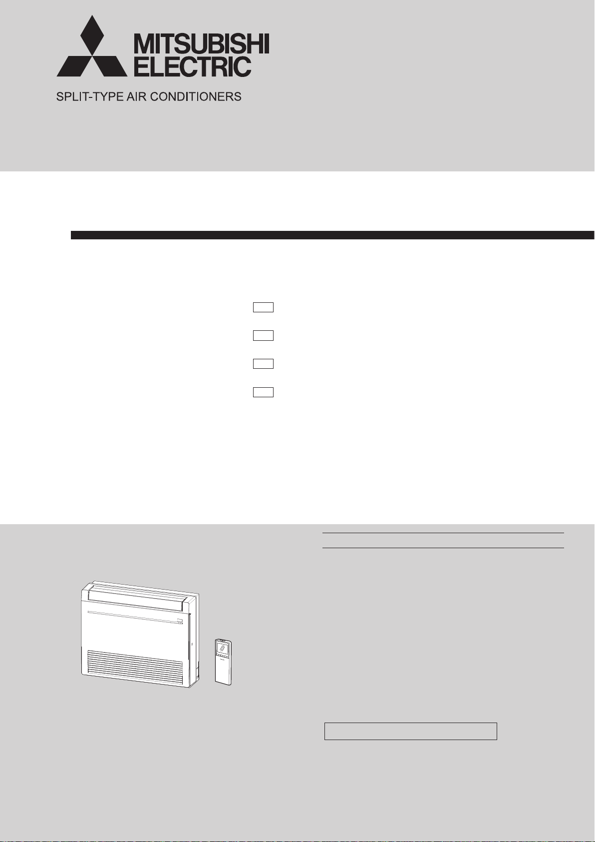
INDOOR UNIT
SERVICE MANUAL
Models
E1
MFZ-KT25VG
MFZ-KT35VG
MFZ-KT50VG
MFZ-KT60VG
-
E1
-
E1
-
E1
-
No. OBH843
MFZ-KT25VG
MFZ-KT35VG
MFZ-KT50VG
MFZ-KT60VG
Outdoor unit service manual
SUZ-M•VA Series (OCH684)
F
MXZ-
CONTENTS
1. TECHNICAL CHANGES ··································· 2
2. SAFETY PRECAUTION ···································· 3
3. PART NAMES AND FUNCTIONS ···················· 7
4. SPECIFICATION ··············································· 8
5. NOISE CRITERIA CURVES ······························ 9
6. OUTLINES AND DIMENSIONS ·······················11
7. WIRING DIAGRAM ·········································· 12
8. REFRIGERANT SYSTEM DIAGRAM ············· 13
9. SERVICE FUNCTIONS ··································· 15
10. MICROPROCESSOR CONTROL ···················· 17
11. TROUBLESHOOTING ····································· 25
12. DISASSEMBLY INSTRUCTIONS ··················· 37
PARTS CATALOG (OBB843)
•VF Series (OBH790)
Page 2

Use the specied refrigerant only
OBH843
Never use any refrigerant other than that specified.
Doing so may cause a burst, an explosion, or fire when the unit is being used, serviced, or disposed of.
Correct refrigerant is specified in the manuals and on the spec labels provided with our products.
We will not be held responsible for mechanical failure, system malfunction, unit breakdown or accidents caused by
failure to follow the instructions.
<Preparation before the repair service>
Prepare the proper tools.
Prepare the proper protectors.
Provide adequate ventilation.
After stopping the operation of the air conditioner, turn off the power-supply breaker and remove the power plug.
Discharge the capacitor before the work involving the electric parts.
<Precautions during the repair service>
Do not perform the work involving the electric parts with wet hands.
Do not pour water into the electric parts.
Do not touch the refrigerant.
Do not touch the hot or cold areas in the refrigeration cycle.
When the repair or the inspection of the circuit needs to be done without turning off the power, exercise great caution not to
touch the live parts.
1
TECHNICAL CHANGES
MFZ-KT25VGMFZ-KT35VGMFZ-KT50VGMFZ-KT60VG-
1. New model
E1
E1
E1
E1
2
Page 3

2
OBH843
SAFETY PRECAUTION
2-1. CAUTIONS RELATED TO NEW REFRIGERANT
Cautions for units utilizing refrigerant R32/R410A
WARNING
1. Warning for service
(1) In case of reconnecting the refrigerant pipes after detaching, make the flared part of pipe re-fabricated.
(2) This unit should be installed in rooms which exceed the floor space specified in outdoor unit installation manual. Refer to
outdoor unit installation manual.
(3) Refrigerant pipes connection shall be accessible for maintenance purposes.
(4) Do not use low temperature solder alloy in case of brazing the refrigerant pipes.
(5) Do not use means to accelerate the defrosting process or to clean, other than those recommended by the manufacturer.
(6) The appliance shall be stored in a room without continuously operating ignition sources (for example: open flames, an
operating gas appliance or an operating electric heater).
(7) Do not pierce or burn.
(8) Be aware that refrigerants may not contain an odour.
(9) Pipe-work shall be protected from physical damage.
(
10
) The installation of pipe-work shall be kept to a minimum.
(
11
) Compliance with national gas regulations shall be observed.
(
12
) Keep any required ventilation openings clear of obstruction.
(
13
) Servicing shall be performed only as recommended by the manufacturer.
(
14
) The appliance shall be stored in a well-ventilated area where the room size corresponds to the room area as specified for
operation.
(
15
) Maintenance, service and repair operations shall be performed by authorized technician with required qualification.
2. Cautions for unit using R32 refrigerant
Basic work procedures are the same as those for conventional units using refrigerant R410A. However, pay careful
attention to the following points.
(1) Information on servicing
(1-1) Checks on the Area
Prior to beginning work on systems containing flammable refrigerants, safety checks are necessary to ensure that the
risk of ignition is minimized.
For repair to the refrigerating systems, (1-3) to (1-7) shall be completed prior to conducting work on the systems.
(1-2) Work Procedure
Work shall be undertaken under a controlled procedure so as to minimize the risk of a flammable gas or vapor being
present while the work is being performed.
(1-3) General Work Area
All maintenance staff and others working in the local area shall be instructed on the nature of work being carried out.
Work in confined spaces shall be avoided. The area around the workspace shall be sectioned off. Ensure that the conditions within the area have been made safe by control of flammable material.
(1-4) Checking for Presence of Refrigerant
The area shall be checked with an appropriate refrigerant detector prior to and during work, to ensure the technician is
aware of potentially toxic or flammable atmospheres. Ensure that the leak detection equipment being used is suitable
for use with all applicable refrigerants, i.e. non-sparking, adequately sealed or intrinsically safe.
(1-5) Presence of Fire Extinguisher
If any hot work is to be conducted on the refrigeration equipment or any associated parts, appropriate fire extinguishing
equipment shall be available to hand.
Have a dry powder or CO2 fire extinguisher adjacent to the charging area.
(1-6) No Ignition Sources
No person carrying out work in relation to a refrigeration system which involves exposing any pipe work shall use any
sources of ignition in such a manner that it may lead to the risk of fire or explosion. All possible ignition sources, including cigarette smoking, should be kept sufficiently far away from the site of installation, repairing, removing and disposal,
during which refrigerant can possibly be released to the surrounding space. Prior to work taking place, the area around
the equipment is to be surveyed to make sure that there are no flammable hazards or ignition risks. “No Smoking” signs
shall be displayed.
(1-7) Ventilated Area
Ensure that the area is in the open or that it is adequately ventilated before breaking into the system or conducting any
hot work. A degree of ventilation shall continue during the period that the work is carried out. The ventilation should
safely disperse any released refrigerant and preferably expel it externally into the atmosphere.
3
Page 4

(1-8) Checks on the Refrigeration Equipment
OBH843
Where electrical components are being changed, they shall be fit for the purpose and to the correct specification. At all
times the manufacturer’s maintenance and service guidelines shall be followed. If in doubt, consult the manufacturer’s
technical department for assistance.
The following checks shall be applied to installations using flammable refrigerants:
The charge size is in accordance with the room size within which the refrigerant containing parts are installed.
•
The ventilation machinery and outlets are operating adequately and are not obstructed.
•
Marking to the equipment continues to be visible and legible. Markings and signs that are illegible shall be corrected.
•
Refrigeration pipe or components are installed in a position where they are unlikely to be exposed to any substance
•
which may corrode refrigerant containing components, unless the components are constructed of materials which are
inherently resistant to being corroded or are suitably protected against being corroded.
(1-9) Checks on Electrical Devices
Repair and maintenance to electrical components shall include initial safety checks and component inspection procedures. If a fault exists that could compromise safety, then no electrical supply shall be connected to the circuit until it is
satisfactorily dealt with. If the fault cannot be corrected immediately but it is necessary to continue operation, an adequate temporary solution shall be used. This shall be reported to the owner of the equipment so all parties are advised.
Initial safety checks shall include that:
capacitors are discharged: this shall be done in a safe manner to avoid possibility of sparking;
•
no live electrical components and wiring are exposed while charging, recovering or purging the system;
•
there is continuity of earth bonding
•
(2) Repairs to Sealed Components
(2-1) During repairs to sealed components, all electrical supplies shall be disconnected from the equipment being worked
upon prior to any removal of sealed covers, etc. If it is absolutely necessary to have an electrical supply to equipment
during servicing, then a permanently operating form of leak detection shall be located at the most critical point to warn
of a potentially hazardous situation.
(2-2) Particular attention shall be paid to the following to ensure that by working on electrical components, the casing is not
altered in such a way that the level of protection is affected. This shall include damage to cables, excessive number of
connections, terminals not made to original specification, damage to seals, incorrect fitting of glands, etc.
Ensure that the apparatus is mounted securely.
Ensure that seals or sealing materials have not degraded to the point that they no longer serve the purpose of preventing the ingress of flammable atmospheres.
Replacement parts shall be in accordance with the manufacturer’s specifications.
(3) Repair to intrinsically Safe Components
Do not apply any permanent inductive or capacitance loads to the circuit without ensuring that this will not exceed the
permissible voltage and current permitted for the equipment in use.
Intrinsically safe components are the only types that can be worked on while live in the presence of a flammable atmosphere. The test apparatus shall be at the correct rating.
Replace components only with parts specified by the manufacturer. Other parts may result in the ignition of refrigerant in
the atmosphere from a leak.
(4) Cabling
Check that cabling will not be subject to wear, corrosion, excessive pressure, vibration, sharp edges or any other adverse
environmental effects. The check shall also take into account the effects of aging or continual vibration from sources such
as compressors or fans.
(5) Detection of Flammable Refrigerants
Under no circumstances shall potential sources of ignition be used in the searching for or detection of refrigerant leaks.
A halide torch (or any other detector using a naked flame) shall not be used.
(6) Leak Detection Methods
Electronic leak detectors may be used to detect refrigerant leaks but, in the case of flammable refrigerants, the sensitivity
may not be adequate, or may need re-calibration. (Detection equipment shall be calibrated in a refrigerant-free area.)
Ensure that the detector is not a potential source of ignition and is suitable for the refrigerant used. Leak detection equipment shall be set at a percentage of the LFL of the refrigerant and shall be calibrated to the refrigerant employed, and the
appropriate percentage of gas (25% maximum) is confirmed.
Leak detection fluids are suitable for use with most refrigerants but the use of detergents containing chlorine shall be
avoided as the chlorine may react with the refrigerant and corrode the copper pipe-work.
If a leak is suspected, all naked flames shall be removed/extinguished.
If a leakage of refrigerant is found which requires brazing, all of the refrigerant shall be recovered from the system, or
isolated (by means of shut off valves) in a part of the system remote from the leak. For appliances containing flammable
refrigerants, oxygen free nitrogen (OFN) shall then be purged through the system both before and during the brazing process.
4
Page 5

(7) Removal and Evacuation
OBH843
When breaking into the refrigerant circuit to make repairs – or for any other purpose conventional procedures shall be
used. However, for flammable refrigerants it is important that best practice is followed since flammability is a consideration. The following procedure shall be adhered to:
• remove refrigerant
• purge the circuit with inert gas
• evacuate
• purge again with inert gas
• open the circuit by cutting or brazing.
The refrigerant charge shall be recovered into the correct recovery cylinders. For appliances containing flammable refrigerants, the system shall be “flushed” with OFN to render the unit safe. This process may need to be repeated several
times.
Compressed air or oxygen shall not be used for purging refrigerant systems.
For appliances containing flammable refrigerants, flushing shall be achieved by breaking the vacuum in the system with
OFN and continuing to fill until the working pressure is achieved, then venting to atmosphere, and finally pulling down to
a vacuum. This process shall be repeated until no refrigerant is within the system. When the final OFN charge is used,
the system shall be vented down to atmospheric pressure to enable work to take place. This operation is absolutely vital
if brazing operations on the pipe-work are to take place.
Ensure that the outlet for the vacuum pump is not close to any ignition sources and that ventilation is available.
(8) Charging Procedures
In addition to conventional charging procedures, the following requirements shall be followed:
Ensure that contamination of different refrigerants does not occur when using charging equipment. Hoses or lines
•
shall be as short as possible to minimize the amount of refrigerant contained in them.
Cylinders shall be kept upright.
•
Ensure that the refrigeration system is earthed prior to charging the system with refrigerant.
•
Label the system when charging is complete (if not already).
•
Extreme care shall be taken not to overfill the refrigeration system.
•
Prior to recharging the system, it shall be pressure-tested with the appropriate purging gas. The system shall be leak-
tested on completion of charging but prior to commissioning. A follow up leak test shall be carried out prior to leaving the
site.
(9) Decommissioning
Before carrying out this procedure, it is essential that the technician is completely familiar with the equipment and all its
detail. It is recommended good practice that all refrigerants are recovered safely. Prior to the task being carried out, an
oil and refrigerant sample shall be taken in case analysis is required prior to re-use of reclaimed refrigerant. It is essential
that electrical power is available before the task is commenced.
a) Become familiar with the equipment and its operation.
b) Isolate system electrically.
c) Before attempting the procedure, ensure that:
• mechanical handling equipment is available, if required, for handling refrigerant cylinders;
• all personal protective equipment is available and being used correctly;
• the recovery process is supervised at all times by a competent person;
• recovery equipment and cylinders conform to the appropriate standards.
d) Pump down refrigerant system, if possible.
e) If a vacuum is not possible, make a manifold so that refrigerant can be removed from various parts of the system.
f) Make sure that cylinder is situated on the scales before recovery takes place.
g) Start the recovery machine and operate in accordance with manufacturer ’s instructions.
h) Do not overfill cylinders. (No more than 80 % volume liquid charge).
i) Do not exceed the maximum working pressure of the cylinder, even temporarily.
j) When the cylinders have been filled correctly and the process completed, make sure that the cylinders and the equip-
ment are removed from site promptly and all isolation valves on the equipment are closed off.
k) Recovered refrigerant shall not be charged into another refrigeration system unless it has been cleaned and checked.
5
Page 6

(10) Labelling
OBH843
Equipment shall be labelled stating that it has been de-commissioned and emptied of refrigerant. The label shall be
dated and signed. For appliances containing flammable refrigerants, ensure that there are labels on the equipment stating the equipment contains flammable refrigerant.
(11) Recovery
When removing refrigerant from a system, either for servicing or decommissioning, it is recommended good practice
that all refrigerants are removed safely. When transferring refrigerant into cylinders, ensure that only appropriate refrigerant recovery cylinders are employed. Ensure that the correct number of cylinders for holding the total system charge
are available. All cylinders to be used are designated for the recovered refrigerant and labelled for that refrigerant (i.e.
special cylinders for the recovery of refrigerant). Cylinders shall be complete with pressure-relief valve and associated
shut-off valves in good working order. Empty recovery cylinders are evacuated and, if possible, cooled before recovery
occurs.
The recovery equipment shall be in good working order with a set of instructions concerning the equipment that is at
hand and shall be suitable for the recovery of all appropriate refrigerants including, when applicable, flammable refrigerants. In addition, a set of calibrated weighing scales shall be available and in good working order. Hoses shall be complete with leak-free disconnect couplings and in good condition. Before using the recovery machine, check that it is in
satisfactory working order, has been properly maintained and that any associated electrical components are sealed to
prevent ignition in the event of a refrigerant release. Consult manufacturer if in doubt.
The recovered refrigerant shall be returned to the refrigerant supplier in the correct recovery cylinder, and the relevant
waste transfer note arranged. Do not mix refrigerants in recovery units and especially not in cylinders. If compressors or
compressor oils are to be removed, ensure that they have been evacuated to an acceptable level to make certain that
flammable refrigerant does not remain within the lubricant. The evacuation process shall be carried out prior to returning
the compressor to the suppliers. Only electric heating to the compressor body shall be employed to accelerate this process. When oil is drained from a system, it shall be carried out safely.
6
Page 7
3
OBH843
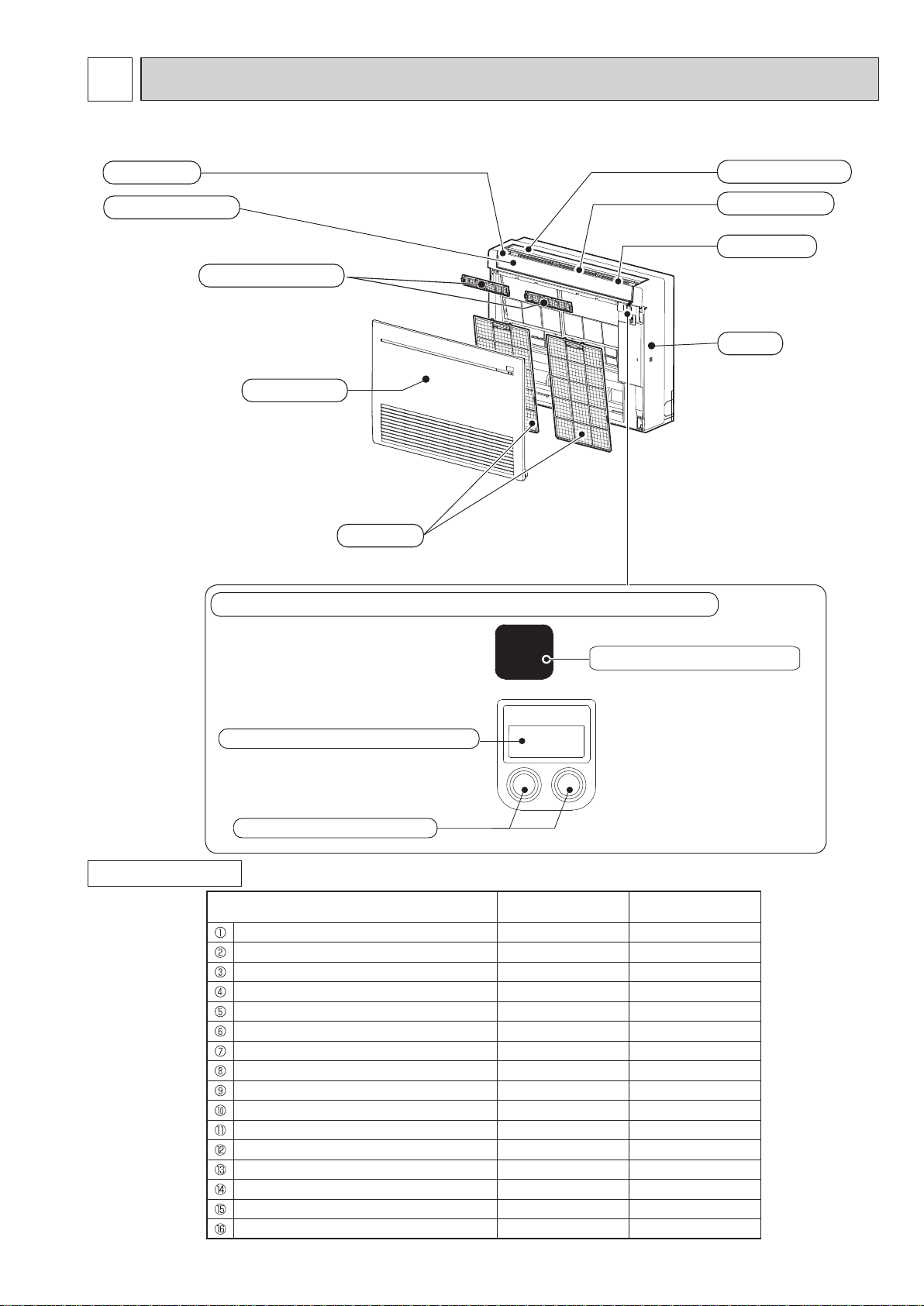
PART NAMES AND FUNCTIONS
MFZ-KT25VG MFZ-KT35VG MFZ-KT50VG MFZ-KT60VG
Air outlet
Multi-flow vane
Air cleaning filter
Horizontal vane
Vertical vane
Fan guard
Panel
Front panel
Air filter
Display and operation section (When the front panel is opened)
ACCESSORIES
E.O
SW
Emergency operation switch
Remote control receiving section
Operation indicator lamp
Model MFZ-KT25/35/50VG MFZ-KT60VG
Remote controller holder 1 1
Fixing screw for 1 3.5 x 16 mm (Black) 2 2
Pipe cover 1 1
Band 2 2
Battery (AAA) for remote controller 2 2
Indoor unit mounting bracket 1 1
Fixing screw for 6 4 x 25 mm 5 5
Wood screw for the indoor unit xation 4 4
Washer of 8 4 4
Felt tape (Used for left or left-rear piping) 1 1
Wireless remote controller 1 1
Air cleaning lter 2 2
Breaker tag 1 1
Breaker notice 1 1
Joint pipe
Pipe cover for joint pipe
7
-
-
1
1
Page 8
4
OBH843
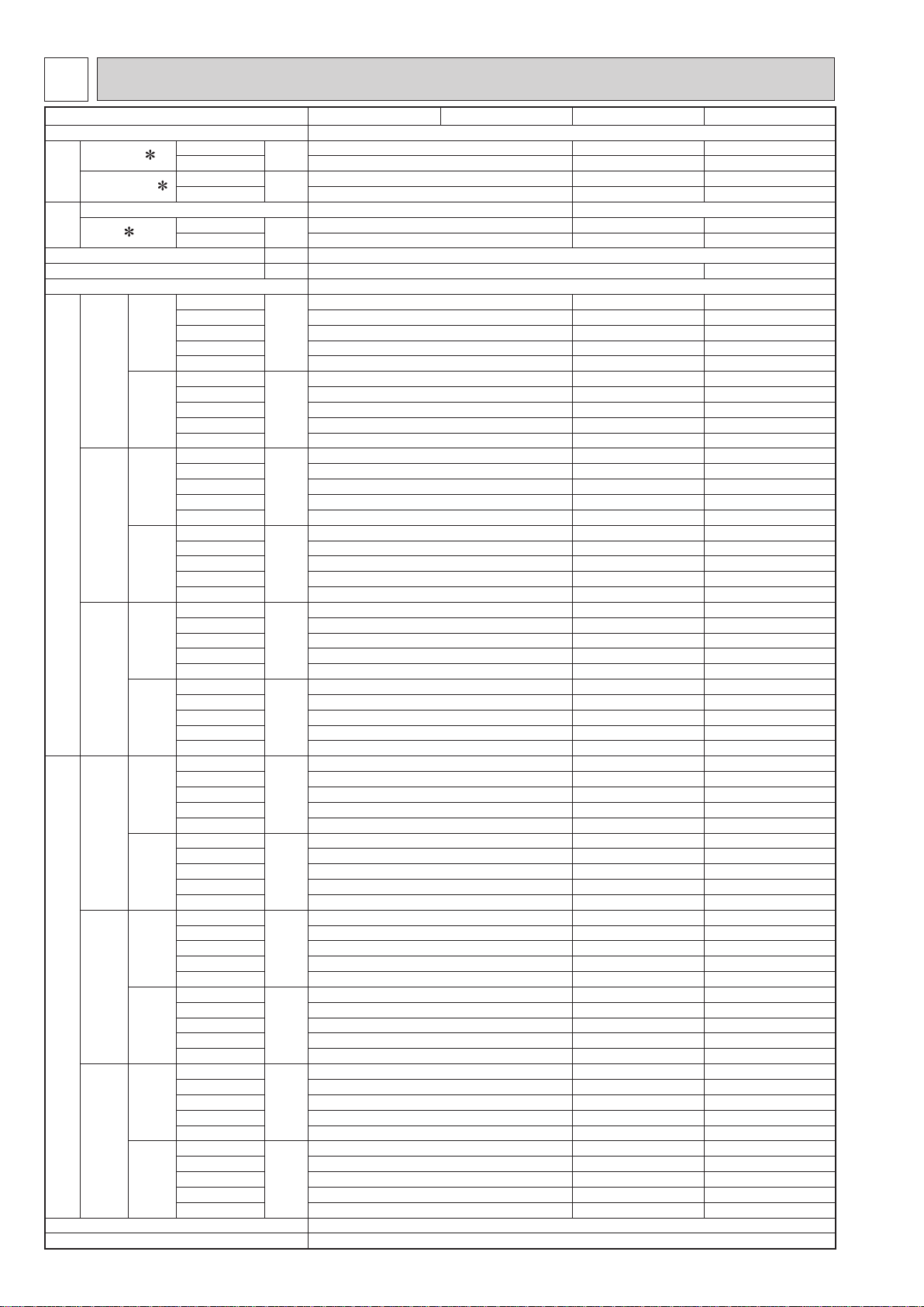
SPECIFICATION
Indoor model
Power supply Single phase 230 V, 50 Hz
Power input 1
Running current 1
Electrical
data
Model RC0J30-Q# RC0J40-P#
Current
Fan
motor
Dimensions W × H × D mm 750 × 600 × 215
Weight kg 14.5 15
Air direction 1 FLOW: 4, 2 FLOW: 4
Special remarks (Single)
Special remarks (Multi)
Fan speed regulator 5
Remote controller model SG191
1
Airow
Sound level
Fan speed
Airow
Sound level
Fan speed
Cooling
Heating 24 52 59
Cooling
Heating 0.20 0.45 0.49
Cooling
Heating 0.17 0.43 0.46
Super High
High 468 624 738
Med. 390 516 576
Cooling
Low 288 402 480
Silent 234 336 336
Super High
High 438 696 750
Med. 336 564 582
Heating
Low 240 462 462
Silent 210 360 360
Super High
High 37 42 46
Med. 31 37 40
Cooling
Low 24 32 36
Silent 19 28 28
Super High
High 37 44 47
Med. 30 40 41
Heating
Low 23 35 35
Silent 19 29 29
Super High
High 900 970 1120
Med. 770 820 900
Cooling
Low 610 670 770
Silent 520 580 580
Super High
High 850 1060 1130
Med. 690 890 910
Heating
Low 530 750 750
Silent 480 610 610
Super High
High 468 624 738
Med. 390 516 576
Cooling
Low 288 402 480
Silent 252 336 336
Super High
High 468 696 750
Med. 378 564 582
Heating
Low 294 462 462
Silent 252 360 360
Super High
High 38 42 46
Med. 33 37 40
Cooling
Low 28 32 36
Silent 23 28 28
Super High
High 39 44 47
Med. 34 40 41
Heating
Low 28 35 35
Silent 24 29 29
Super High
High 900 970 1120
Med. 770 820 900
Cooling
Low 610 670 770
Silent 550 580 580
Super High
High 900 1060 1130
Med. 750 890 910
Heating
Low 620 750 750
Silent 550 610 610
W
A
A
3
m
3
m
dB(A)
dB(A)
rpm
rpm
3
m
3
m
dB(A)
dB(A)
rpm
rpm
/h
/h
/h
/h
MFZ-KT25VG MFZ-KT35VG MFZ-KT50VG MFZ-KT60VG
20 37 63
0.17 0.34 0.55
0.14 0.32 0.52
534 738 900
582 840 876
41 48 53
44 49 51
1000 1120 1330
1080 1250 1300
540 738 900
582 840 876
43 48 53
44 49 51
1010 1120 1330
1080 1250 1300
8
Page 9
NOTE: Test conditions are based on ISO 5151.
OCTAVE BAND SOUND PRESSURE LEVEL, dB re 0.0002 MICRO BAR
OCTAVE BAND SOUND PRESSURE LEVEL, dB re 0.0002 MICRO BAR
OBH843
Cooling: Indoor Dry-bulb temperature 27°C Wet-bulb temperature 19°C
Outdoor Dry-bulb temperature 35°C
Heating: Indoor Dry-bulb temperature 20°C
Outdoor Dry-bulb temperature 7°C Wet-bulb temperature 6°C
1 Measured under rated operating frequency.
Specifications and rating conditions of main electric parts
Model
Item
Fuse (F11) T3.15AL250V
Horizontal vane motor (Front) (MV1) 12 V DC 250 Ω
Horizontal vane motor (Back) (MV2) 12 V DC 250 Ω
Multi-ow vane motor (MV3) 12 V DC 350 Ω
Terminal block (TB) 3P
Varistor (NR11) S10K300E2K1
MFZ-KT25VG MFZ-KT35VG MFZ-KT50VG MFZ-KT60VG
5
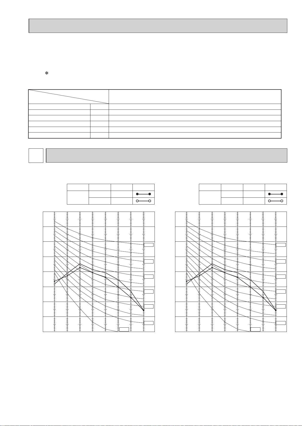
NOISE CRITERIA CURVES
MFZ-KT25VG MFZ-KT35VG
FAN SPEED
Super High
80
70
60
50
40
30
20
FUNCTION
COOLING
HEATING
SPL(dB(A))
41
44
LINE
NC-70
NC-60
NC-50
NC-40
NC-30
80
70
60
50
40
30
20
FAN SPEED
Super High
FUNCTION
COOLING
HEATING
SPL(dB(A))
41
44
LINE
NC-70
NC-60
NC-50
NC-40
NC-30
10
0
63 125 250 500 1000 2000 4000 8000
BAND CENTER FREQUENCIES, Hz
NC-10
NC-20
10
NC-20
0
63 125 250 500 1000 2000 4000 8000
BAND CENTER FREQUENCIES, Hz
NC-10
9
Page 10
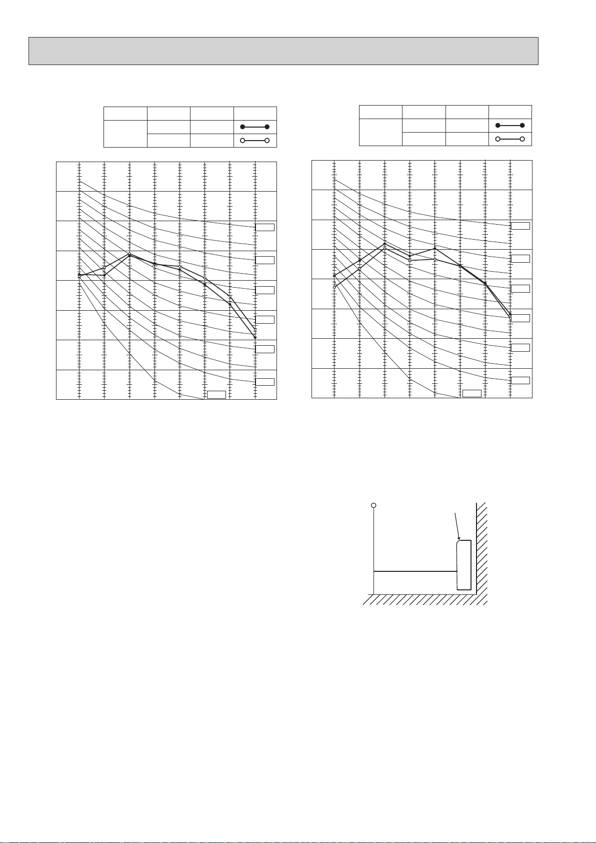
OCTAVE BAND SOUND PRESSURE LEVEL, dB re 0.0002 MICRO BAR
MFZ-KT50VG
OCTAVE BAND SOUND PRESSURE LEVEL, dB re 0.0002 MICRO BAR
OBH843
MFZ-KT60VG
FAN SPEED
Super High
80
70
60
50
40
30
20
10
0
63 125 250 500 1000 2000 4000 8000
BAND CENTER FREQUENCIES, Hz
FUNCTION
COOLING
HEATING
SPL(dB(A))
48
49
NC-10
LINE
NC-70
NC-60
NC-50
NC-40
NC-30
NC-20
FAN SPEED
Super High
80
70
60
50
40
30
20
10
0
63 125 250 500 1000 2000 4000 8000
BAND CENTER FREQUENCIES, Hz
FUNCTION
COOLING
HEATING
SPL(dB(A))
LINE
53
51
NC-70
NC-60
NC-50
NC-40
NC-30
NC-20
NC-10
Test conditions
Cooling : Dry-bulb temperature 27 °C Wet-bulb temperature 19 °C
Heating : Dry-bulb temperature 20 °C
MICROPHONE
INDOOR UNIT
1m
WALL
1m
10
Page 11
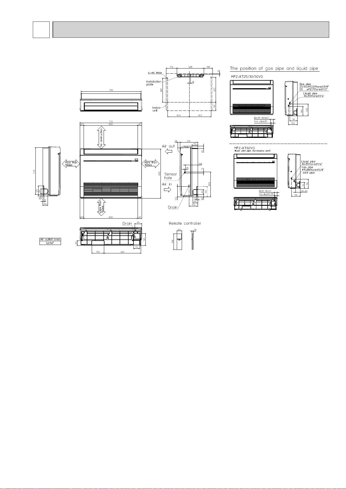
6
OBH843
OUTLINES AND DIMENSIONS
MFZ-KT25VG MFZ-KT35VG MFZ-KT50VG MFZ-KT60VG
Unit: mm
11
Page 12
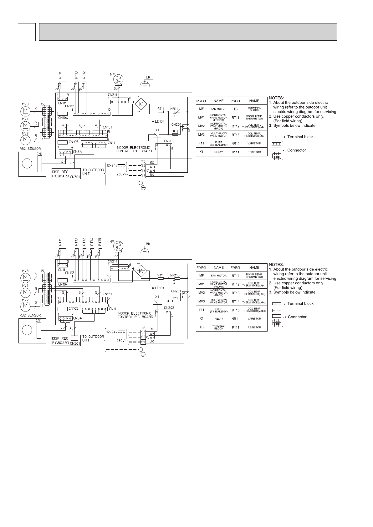
7
OBH843
MFZ-KT25VG MFZ-KT35VG MFZ-KT50VG
WIRING DIAGRAM
MFZ-KT60VG
12
Page 13
8
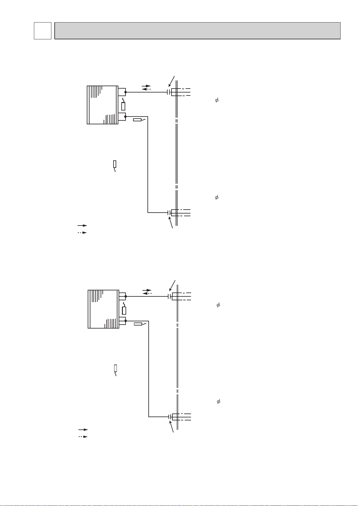
OBH843
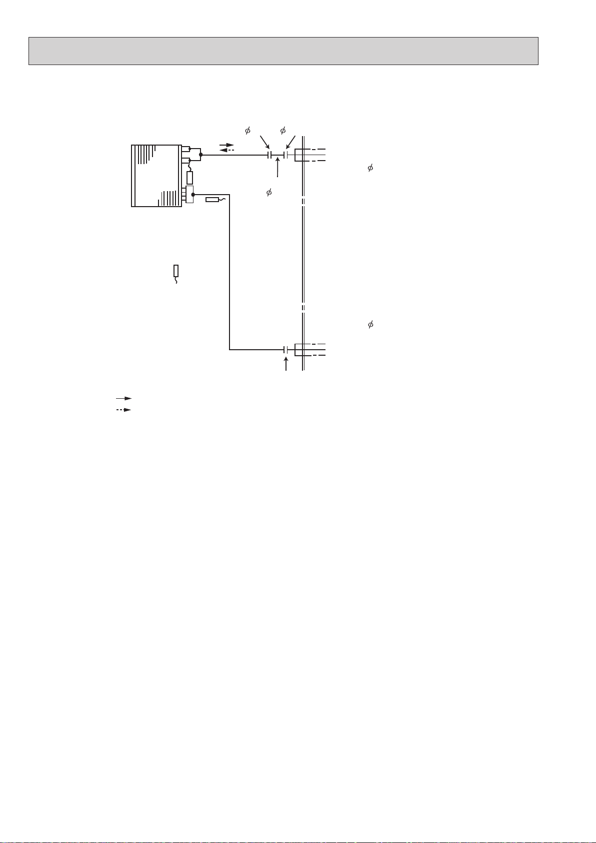
REFRIGERANT SYSTEM DIAGRAM
MFZ-KT25VG MFZ-KT35VG
Indoor
heat
exchanger
Indoor coil
thermistor
RT13 (sub)
Room temperature
thermistor
RT11
Refrigerant flow in cooling
Refrigerant flow in heating
Indoor coil
thermistor
RT12 (main)
Distributor
Unit: mm
Flared connection
Refrigerant pipe 9.52
(with heat insulator)
Refrigerant pipe 6.35
(with heat insulator)
Flared connection
MFZ-KT50VG
Indoor
heat
exchanger
Room temperature
thermistor
RT11
Refrigerant flow in cooling
Refrigerant flow in heating
Indoor coil
thermistor
RT12 (main)
Distributor
Indoor coil
thermistor
RT13 (sub)
Flared connection
Refrigerant pipe 12.7
(with heat insulator)
Refrigerant pipe 6.35
(with heat insulator)
Flared connection
13
Page 14
MFZ-KT60VG
OBH843
Unit: mm
Flared connection
( 12.7) ( 15.88)
Indoor
heat
exchanger
Room temperature
thermistor
RT11
Refrigerant flow in cooling
Refrigerant flow in heating
Indoor coil
thermistor
RT12 (main)
Distributor
Indoor coil
thermistor
RT14, RT15
(main)
RT13 (sub)
Joint pipe
( 12.7)
Flared connection
Refrigerant pipe 15.88
(with heat insulator)
Refrigerant pipe 6.35
(with heat insulator)
14
Page 15

9
Indoor electronic
OBH843
SERVICE FUNCTIONS
MFZ-KT25VG MFZ-KT35VG MFZ-KT50VG MFZ-KT60VG
9-1. TIMER SHORT MODE
For service, the following set time can be shortened by bridging the timer short mode point on the electronic control P.C.
•
board. (Refer to 11-7.)
The set time for the ON/OFF timer can be reduced to 1 second for each minute.
•
After the breaker is turned on, the time for starting the compressor, which normally takes 3 minutes, can be reduced to 1
•
minute. Restarting the compressor, which takes 3 minutes, cannot be reduced.
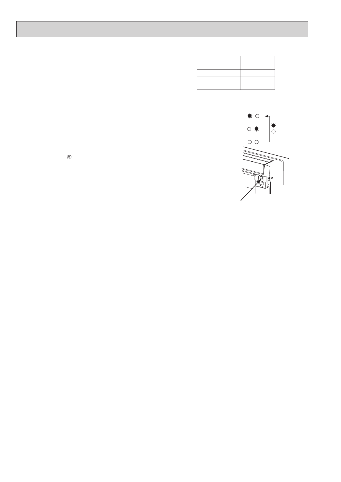
9-2. HOW TO SET REMOTE CONTROLLER EXCLUSIVELY FOR A PARTICULAR INDOOR UNIT
A maximum of 4 indoor units with wireless remote controllers can be used in a room.
To operate the indoor units individually with each remote controller, assign a number to each remote controller according
to the number of the indoor unit.
This setting can be set only when all the following conditions are met:
• The remote controller is powered OFF.
• Weekly timer is not set.
• Weekly timer is not being edited.
1. How to modify the electronic control P.C. board
Turn OFF the power supply before modification. To assign a number to each indoor unit , cut off “JR05” and “JR06” on the
electronic control P.C. board as shown in Table 1. (Refer to 11-7.)
Table 1
JR05
Unit No. 1
Unit No. 2
Unit No. 3
Unit No. 4
2. How to set the remote controller
(1) Hold down
(2) Press
Each press of
(3) Press
After the setting, turn ON the power supply and with the remote controller headed towards the indoor unit, press the
STOP/OPERATE (OFF/ON) button. If 1 or 2 beeps is heard from the indoor unit, the setting is completed correctly.
The remote controller that first sends a signal to an indoor unit will be regarded as the remote controller for the indoor
unit.
Once they are set, the indoor unit will only receive the signal from the assigned remote controller afterwards.
button again and assign a number to each remote controller.
button to complete the pairing setting.
No modification
Cut off JR05
No modification
Cut off JR05
button on the remote controller for 2 seconds to enter the pairing mode.
button advances the number in the following order: 1 → 2 → 3 → 4.
JR06
No modification
No modification
Cut off JR06
Cut off JR06
VARISTOR (NR11)
R111
CN211
control P.C. Board
Fuse (F11)
JR05
JR06
CN151
15
Page 16

9-3. AUTO RESTART FUNCTION
OBH843
When the indoor unit is controlled with the remote controller, the operation mode, the set temperature, and the fan speed
are memorized by the indoor electronic control P.C. board. “AUTO RESTART FUNCTION” automatically starts operation
in the same mode just before the shutoff of the main power.
Operation
If the main power has been cut, the operation settings remain.
After the power is restored, the unit restarts automatically according to the memory.
(However, it takes at least 3 minutes
for the compressor to start running.)
How to disable “AUTO RESTART FUNCTION”
Turn off the main power for the unit.
Cut the Jumper wire to JR77 on the indoor electronic control P.C. board. (Refer to 11-7.)
CN201 F11
L101
JR77
CN211
CN111
C111
CN104
T111
CN105
CN123
NOTE:
• The operation settings are memorized when 10 seconds have passed after the indoor unit was operated with the remote
controller.
• If main power is turned OFF or a power failure occurs while AUTO START/STOP timer is active, the timer setting is can-
celled.
• If the unit has been off with the remote controller before power failure, the auto restart function does not work as the
power button of the remote controller is off.
• To prevent breaker OFF due to the rush of starting current, systematize other home appliance not to turn ON at the
same time.
• When some air conditioners are connected to the same supply system, if they are operated before power failure, the
starting current of all the compressors may flow simultaneously at restart.
Therefore, the special counter measures are required to prevent the main voltage-drop or the rush of the starting cur-
rent by adding to the system that allows the units to start one by one.
1616
Page 17

10
OBH843
MICROPROCESSOR CONTROL
MFZ-KT25VG MFZ-KT35VG MFZ-KT50VG MFZ-KT60VG
WIRELESS REMOTE CONTROLLER
Signal transmitting section
Distance of signal :
About 6 m
Beep(s) is (are) heard from
the indoor unit when the
signal is received.
OPERATION SELECT button
ECONO COOL button
Operation display section
AMPM AMPM
TEMPERATURE buttons
i-save button
STOP/OPERATE
(OFF/ON) button
Indication of
remote controller
model is on back
FAN SPEED CONTROL button
VANE CONTROL button
TIME, TIMER set buttons
FORWARD button
BACKWARD button
WEEKLY TIMER
set buttons
RESET button
CLOCK button
Lid
Slide the lid down
to open the remote
controller. Slide it down
further to get to the
weekly timer buttons.
NOTE: Last setting will be stored after the unit is turned OFF with the remote controller. Indoor unit receives the signal of the
remote controller with beeps.
INDOOR UNIT DISPLAY SECTION
Operation Indicator lamp
The operation indicator at the right side of the indoor unit indicates the operation state.
•The following indication applies regardless of shape of the indication.
Indication Operation state Room temperature
The unit is operating to
reach the set temperature
The room temperature is
approaching the set temperature
Standby mode (only during
multi system operation)
10-1. COOL ( ) OPERATION
(1) Press STOP/OPERATE (OFF/ON) button.
OPERATION INDICATOR lamp of the indoor unit turns on with a beep tone.
(2) Select COOL mode with OPERATION SELECT button.
(3) Press TEMPERATURE buttons TEMP
1. Coil frost prevention
The compressor operational frequency is controlled by the temperature of the indoor heat exchanger to prevent the coil
from frosting.
When the temperature of indoor heat exchanger becomes too low, the coil frost prevention mode works.
The indoor fan operates at the set speed and the compressor stops. This mode continues until the temperature of indoor
heat exchanger rises.
2. Low outside temperature operation
When the outside temperature is lower, low outside temperature operation starts, and the outdoor fan slows or stops.
3. Indoor fan speed control
When the thermostat turns OFF, the indoor fan operates at the setting fan speed.
About 2°C or more
away from set temperature
About 1 to 2°C from
set temperature
Lit
Blinking
Not lit
—
or button to select the set temperature. The setting range is 16 - 31°C.
17
Page 18

10-2. DRY ( ) OPERATION
OBH843
(1) Press STOP/OPERATE (OFF/ON) button.
OPERATION INDICATOR lamp of the indoor unit turns on with a beep tone.
(2) Select DRY mode with OPERATION SELECT button.
(3) The set temperature is determined from the initial room temperature.
1. Coil frost prevention
Coil frost prevention works the same way as that in COOL mode. (10-1.1.)
2. Low outside temperature operation
Low outside temperature operation works the same way as that in COOL mode. (10-1.2.)
3. Indoor fan speed control
Indoor fan speed control works the same way as that in COOL mode. (10-1.3.)
However in AUTO setting, the fan speed changes.
10-3. FAN ( ) OPERATION
(1) Press STOP/OPERATE (OFF/ON) button.
OPERATION INDICATOR lamp of the indoor unit turns on with a beep tone.
(2) Select FAN mode with OPERATION SELECT button.
(3) Select the desired fan speed. When AUTO, it becomes Low.
Only indoor fan operates.
Outdoor unit does not operate.
NOTE: Temperature cannot be set during FAN mode.
10-4. HEAT ( ) OPERATION
(1) Press STOP/OPERATE (OFF/ON) button.
OPERATION INDICATOR lamp of the indoor unit turns on with a beep tone.
(2) Select HEAT mode with OPERATION SELECT button.
(3) Press TEMPERATURE buttons TEMP
1. Cold air prevention control
When the compressor is not operating or is starting, and the temperature of indoor heat exchanger and/or the room temperature is low or when defrosting is being done, the indoor fan will stop or rotate in Very Low speed.
2. High pressure protection
The compressor operational frequency is controlled by the temperature of the indoor heat exchanger to prevent the condensing pressure from increasing excessively.
When the temperature of indoor heat exchanger becomes too high, the high pressure protection works.
This mode continues until the temperature of indoor heat exchanger falls.
3. Defrosting
Defrosting starts when the temperature of outdoor heat exchanger becomes too low.
The compressor stops once, the indoor/outdoor fans stop, the 4-way valve reverses, and the compressor re-starts.
This mode continues until the temperature of outdoor heat exchanger rises or the fixed time passes.
or button to select the set temperature. The setting range is 16 - 31°C.
10-5. AUTO CHANGE OVER ··· AUTO MODE OPERATION
Once set temperature is set, unit operation is switched automatically between COOL and HEAT operation.
1. Mode selection
(1) Initial mode
At first indoor unit operates only indoor fan with outdoor unit OFF for 3 minutes to detect present room temperature.
Following the conditions below, operation mode is selected.
If the room temperature thermistor RT11 reads more than set temperature, COOL mode is selected.
If the room temperature thermistor RT11 reads set temperature or less, HEAT mode is selected.
(2) Mode change
In case of the following conditions the operation mode is changed.
COOL mode changes to HEAT mode when 15 minuets have passed with the room temperature 2 degrees below the
set temperature.
HEAT mode changes to COOL mode when 15 minuets have passed with the room temperature 2 degrees below the
set temperature.
In the other cases than the above conditions, the present operation mode is continued.
NOTE 1: Mode selection is performed when multi standby (refer to NOTE 2) is released and the unit starts operation
with ON-timer.
NOTE 2: If 2 or more indoor units are operating in multi system, there might be a case that the indoor unit, which is
operating in AUTO (
of standby.
NOTE 3: At the beginning of AUTO mode, the airflow direction and the fan speed are set to AUTO and the air outlet
selection is set to 2 FLOW.
), cannot change over the other operating mode (COOL ↔ HEAT) and becomes a state
18
Page 19

10-6. AUTO VANE OPERATION
OBH843
1. Horizontal vane (Horizontal vane/Multi-flow vane)
(1) Vane motor drive
These models are equipped with a stepping motors for the horizontal vanes. The rotating direction, speed, and angle
of the motor are controlled by pulse signals (approximately 12 V) transmitted from indoor microprocessor.
(2) The horizontal vane angle and mode change as follows by pressing VANE CONTROL (
(AUTO) (2) (3) (4)(1) (SWING)
(3) Positioning
The vane presses the vane stopper once to confirm the standard position and then moves to the set angle.
Confirming of standard position is performed in case of follows.
(a) The power supply turns on.
(b) The operation starts or finishes (including timer operation).
(c) The test run starts.
(d) The multi-standby starts or finishes.
(e) Every time the vane has swung more than the specified numbers of times.
( f) The horizontal vane automatically moves in certain intervals to determine its position, and then it returns to set
position.
(g) The vane operates for the dew prevention.
(4) Air outlet selection
The air outlet(s) can be selected by pressing to VANE CONTROL (
When 2 FLOW is selected, air blows from the top and the front of the unit. When 1 FLOW is selected, air blows only
from the top of the unit.
) button.
) button.
(2 FLOW) (1 FLOW)
The multi-flow vane is automatically set to the appropriate position.
In HEAT, the multi-flow vane automatically changes its position according to the indoor fan speed.
Even if 2 FLOW is selected, air will blow only from the top of the unit in the following conditions:
• During COOL/DRY: The room temperature is close to set temperature.
The air conditioner has operated for 0.5 to 1 hour.
• During HEAT: The airflow temperature is low. (During defrosting operation, start of operation, etc.)
NOTE:
Movement at the start of the 2 FLOW operation
• COOL/DRY, HEAT: It takes 0.5 to 1 minute to start the 2 FLOW operation.
• HEAT: When cold air blows out from the air outlet, the multi-flow vane may stop moving for up to 10 minutes to
make and blow out warm air.
19
Page 20

(5) VANE AUTO (
OBH843
In VANE AUTO mode, the microprocessor automatically determines the vane angle to make the optimum room temperature distribution.
In COOL, DRY and FAN operation
2 FLOW: Vane angle is fixed to position 2.
1 FLOW: Vane angle is fixed to position 1. 1 FLOW: Vane angle is fixed to position 3.
(6) STOP (operation OFF) and ON TIMER standby
In the following cases, the horizontal vane returns to the closed position.
(a) When STOP/OPERATE (OFF/ON) button is pressed (POWER OFF).
(b) When the operation is stopped by the emergency operation.
(c) When ON TIMER is ON standby.
(7) Dew prevention
During COOL or DRY operation with the vane angle at Angle 3 or 4 when the compressor cumulative operation time
exceeds 1 hour, the vane angle automatically changes to Angle 1 for dew prevention.
(8) SWING (
By selecting SWING mode with VANE CONTROL button, the horizontal vanes swing vertically.
The remote controller displays " ". SWING mode is cancelled when VANE CONTROL button is pressed once again.
(9) Cold air prevention in HEAT operation
The horizontal vane position is set to Upward.
(
10
) ECONO COOL ( ) operation (ECONOmical operation)
When ECONO COOL button is pressed in COOL mode, set temperature is automatically set 2°C higher by the
microprocessor. However, the temperature on the LCD screen on the remote controller is not changed. Also the
horizontal vane swings in various cycle.
SWING operation makes you feel cooler than set temperature. So, even though the set temperature is higher, the
air conditioner can keep comfort. As a result, energy can be saved.
To cancel this operation, select a different mode or press one of the following buttons in ECONO COOL operation:
ECONO COOL, VANE CONTROL button.
) mode
In HEAT operation
2 FLOW: Vane angle is fixed to position 2.
) mode
20
Page 21

10-7. TIMER OPERATION
OBH843
1. How to set the time
(1) Check that the current time is set correctly.
NOTE: Timer operation will not work without setting the current time. Initially “0:00” blinks at the current time display
of TIME MONITOR, so set the current time correctly with CLOCK button.
How to set the current time
(a) Press the CLOCK button.
(b) Press the TIME SET buttons (
• Each time FORWARD button (
button (
• Pressing those buttons longer, the set time increases/decreases by 10 minutes.
(c) Press the CLOCK set button.
(2) Press STOP/OPERATE (OFF/ON) button to start the air conditioner.
(3) Set the time of timer.
ON timer setting
(a) Press ON TIMER button(
(b) Set the time of the timer using TIME SET buttons (
OFF timer setting
(a) Press OFF TIMER button (
(b) Set the time of the timer using TIME SET buttons (
Each time FORWARD button ( ) is pressed, the set time increases by 10 minutes: each time BACKWARD but-
ton (
2. To release the timer
To release ON timer, press ON TIMER button (
To release OFF timer, press OFF TIMER button(
TIMER is cancelled and the display of set time disappears.
) is pressed, the set time decreases by 1 minute.
) is pressed, the set time decreases by 10 minutes.
and ) to set the current time.
) is pressed, the set time increases by 1 minute, and each time BACKWARD
) during operation.
) during operation.
).
).
and ).
and ).
PROGRAM TIMER
• OFF timer and ON timer can be used in combination. The set time that is reached first will operate first.
” and “ ” display shows the order of OFF timer and ON timer operation.
• “
(Example 1) The current time is 8:00 PM.
The unit turns off at 11:00 PM, and on at 6:00 AM.
NOTE: If the main power is turned OFF or a power failure occurs while ON/OFF timer is active, the timer setting is can-
celled. As these models are equipped with an auto restart function, the air conditioner starts operating with timer
cancelled when power is restored.
(Example 2) The current time is 11:00 AM.
The unit turns on at 5:00 PM, and off at 9:00 PM.
21
Page 22
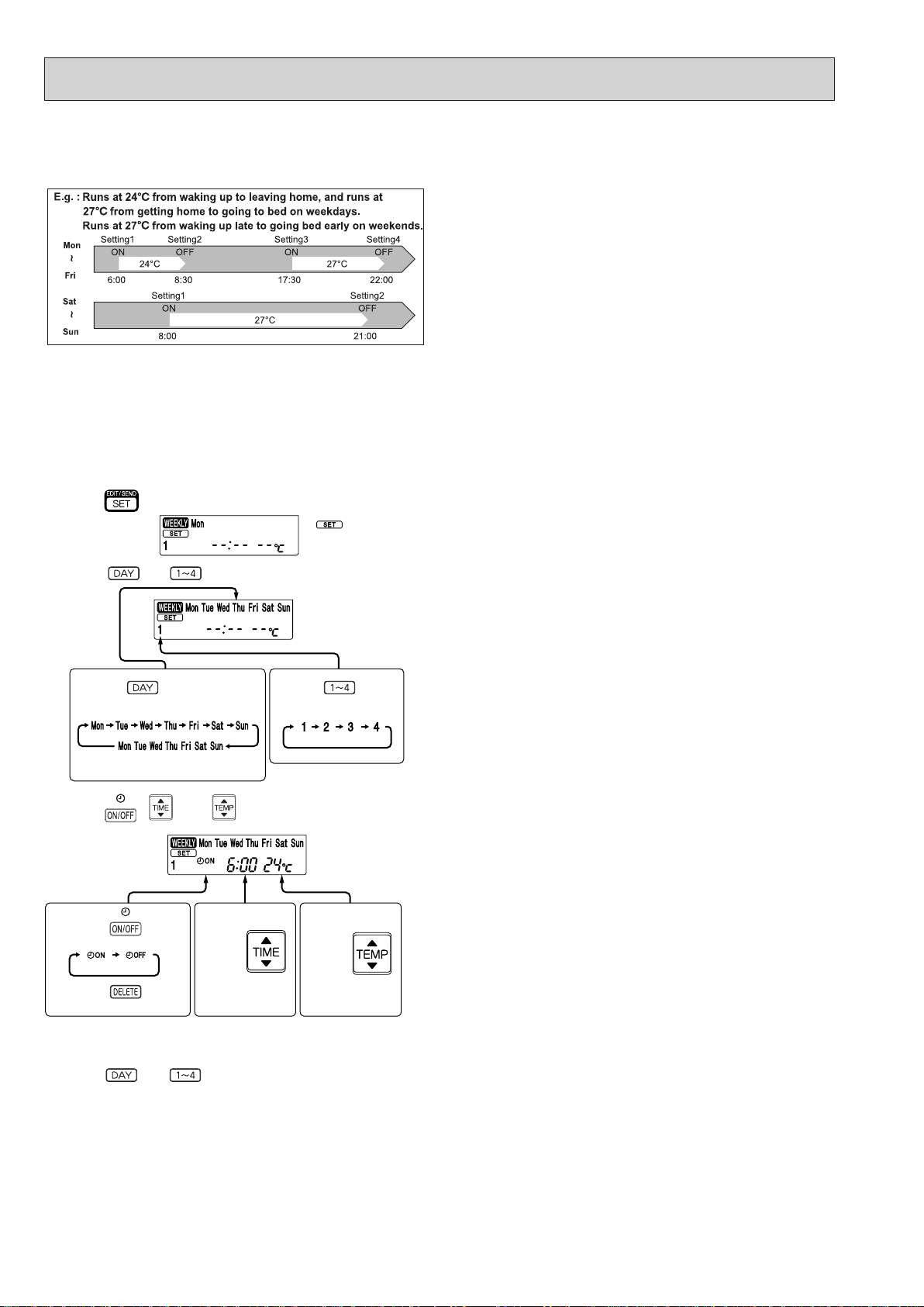
10-8. WEEKLY TIMER OPERATION
OBH843
• A maximum of 4 ON or OFF timers can be set for individual days of the week.
• A maximum of 28 ON or OFF timers can be set for a week.
NOTE:
• The simple ON/OFF timer setting is available while the weekly timer is on. In this case, the ON/OFF timer has priority over the
weekly timer; the weekly timer operation will start again after the simple ON/OFF timer is complete.
• When the weekly timer is set, temperature cannot be set to 10°C.
• The weekly timer operation and i-save operation cannot be used together.
1. How to set the weekly timer
* Make sure that the current time and day are set correctly.
(1) Press button to enter the weekly timer setting mode.
*
blinks.
(2) Press
and buttons to select setting day and number.
E.g. : [Mon Tue ... Sun]
and [1] are selected.
Pressing selects the day of
the week to be set.
* All days can be selected.
Pressing selects
the setting number.
(3) Press , , and buttons to set ON/OFF, time, and temperature.
E.g. : [ON], [6:00]
and [24°C] are
selected.
Pressing
selects ON/OFF timer.
Pressing
deletes timer setting.
* Hold down the button to change the time quickly.
* The temperature can be set between 16 °C and 31 °C at weekly timer.
Pressing
adjusts the time.
Pressing
adjusts the temperature.
Press and buttons to continue setting the timer for other days and/or numbers.
22
Page 23

(4) Press
OBH843
NOTE:
• Press
indoor unit for 3 seconds.
button to complete and transmit the weekly timer setting.
button to transmit the setting information of weekly timer to the indoor unit. Point the remote controller toward the
* which was blink-
ing goes out, and the
current time will be
displayed.
• When setting the timer for more than one day of the week or one number,
setting. Press
• Press
timer settings. Point the remote controller toward the indoor unit.
(5) Press button to turn the weekly timer ON. ( lights.)
•When the weekly timer is ON, the day of the week whose timer setting is complete, will light.
Press
NOTE:
The saved settings will not be cleared when the weekly timer is turned OFF.
button to enter the weekly timer setting mode, and press and hold button for 5 seconds to erase all weekly
button again to turn the weekly timer OFF. ( goes out.)
button once after all the settings are complete. All the weekly timer settings will be saved.
button does not have to be pressed per each
2. Checking weekly timer setting
(1) Press button to enter the weekly timer setting mode.
*
(2) Press
(3) Press
blinks.
or buttons to view the setting of the particular day or number.
button to exit the weekly timer setting.
10-9. i-save ( ) OPERATION
1. How to set i-save operation
(1) Press STOP/OPERATE (OFF/ON) button.
(2) Select COOL or HEAT mode.
(3) Press i-save button.
(4) Set the temperature, fan speed, airow direction, and 2 FLOW/1 FLOW for i-save operation.
NOTE:
• i-save operation cannot be selected during DRY, FAN or AUTO mode operation.
• The setting range of HEAT mode i-save operation is 10°C and 16 - 31°C.
• 2 groups of setting can be saved. (One for COOL, one for HEAT)
• i-save operation and the weekly timer operation cannot be used together.
2. How to cancel operation
• Press i-save button again.
• i-save operation can also be cancelled by pressing OPERATION SELECT button to change the operation mode.
The same setting is selected from the next time by simply pressing i-save button.
23
Page 24
10-10. EMERGENCY/TEST OPERATION
OBH843
In the case of test run operation or emergency operation, use
EMERGENCY OPERATION switch on the right side of the indoor unit.
Emergency operation is available when the remote controller is missing or has failed, or when the batteries in the remote controller are
running down. The unit will start and OPERATION INDICATOR lamp
will light up.
The first 30 minutes of operation is the test run operation. This operation is for servicing. The indoor fan runs at High speed and the temperature control does not work. In COOL MODE, the air outlet selection is set to 2 FLOW during the test run operation.
After 30 minutes of test run operation, the system shifts to
EMERGENCY COOL/HEAT MODE with a set temperature of 24°C.
The fan speed shifts to Medium.
The coil frost prevention works even in the test run or the emergency
operation.
In the test run or emergency operation, the horizontal vane operates
in VANE AUTO (
Emergency operation continues until EMERGENCY OPERATION
switch is pressed once or twice or the unit receives any signal from
the remote controller. In the latter case, normal operation will start.
NOTE: Do not press EMERGENCY OPERATION switch during nor-
mal operation.
) mode.
Operation mode COOL/HEAT
Set temperature 24°C
Fan speed Medium
Horizontal vane Auto
Air outlet 2 FLOW
The operation mode is indicated by the Operation
Indicator lamp as following
Operation Indicator lamp
EMERGENCY COOL
EMERGENCY HEAT
STOP
Emergency
operation switch
(E.O. SW)
↓
↓
Lit
Not lit
10-11. 3-MINUTE TIME DELAY OPERATION
When the system turns OFF, compressor will not restart for 3 minutes as 3-minute time delay function operates to protect
compressor from overload.
24
Page 25
11
<Incorrect>
<Correct>
OBH843
TROUBLESHOOTING
MFZ-KT25VG MFZ-KT35VG MFZ-KT50VG MFZ-KT60VG
11-1. CAUTIONS ON TROUBLESHOOTING
1. Before troubleshooting, check the following
1) Check the power supply voltage.
2) Check the indoor/outdoor connecting wire for miswiring.
2. Take care of the following during servicing
1) Before servicing the air conditioner, be sure to turn OFF the main unit first with the remote controller, and then after
confirming the horizontal vane is closed, turn OFF the breaker.
2) Be sure to turn OFF the power supply before removing the front panel, the cabinet, the top panel, and the P.C. board.
3) When removing the P.C. board, hold the edge of the board with care NOT to apply stress on the components.
4) When connecting or disconnecting the connectors, hold the connector housing. DO NOT pull the lead wires.
Lead wiring
3. Troubleshooting procedure
1) Check if the OPERATION INDICATOR lamp on the indoor unit is blinking ON and OFF to indicate an abnormality.
To make sure, check how many times the OPERATION INDICATOR lamp is blinking ON and OFF before starting
service work.
2) Before servicing, check that the connector and terminal are connected properly.
3) When the electronic control P.C. board seems to be defective, check the copper foil pattern for disconnection and the
components for bursting and discoloration.
4) When troubleshooting, Refer to 11-2, 11-3 and 11-4.
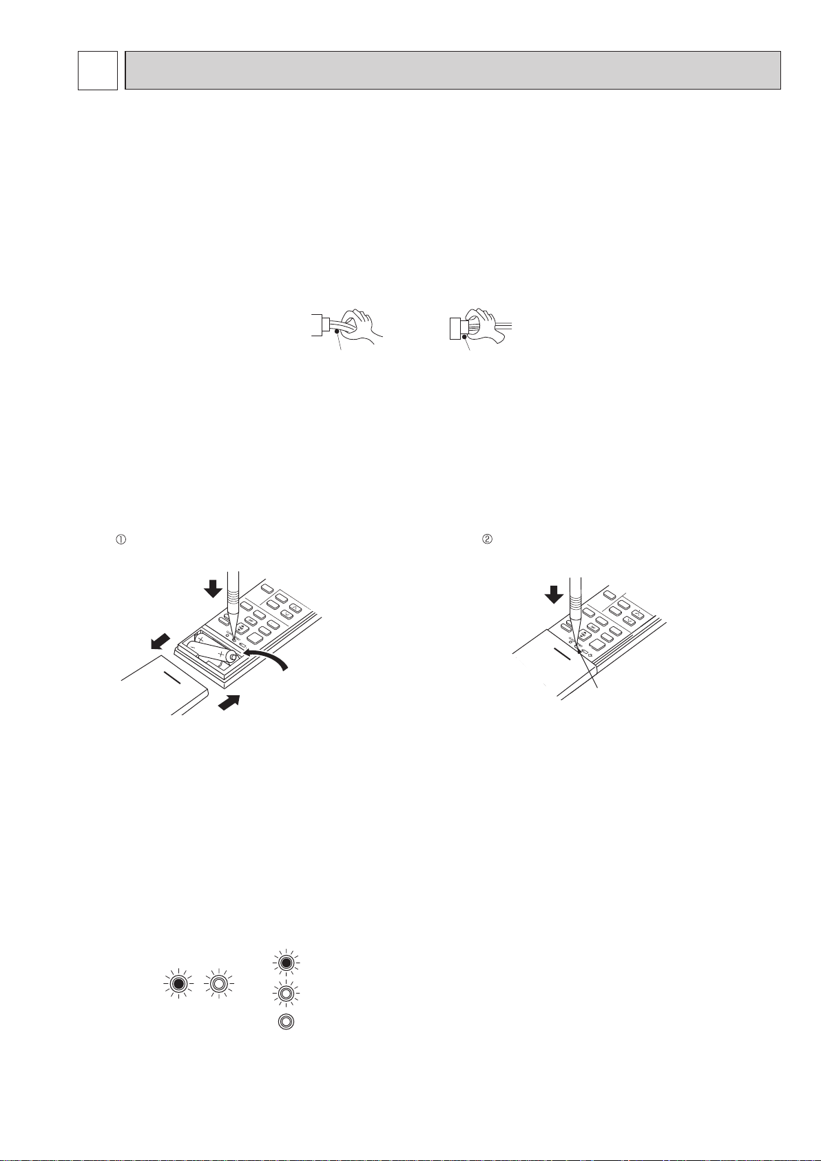
4. How to replace batteries
Weak batteries may cause the remote controller malfunction.
In this case, replace the batteries to operate the remote controller normally.
Remove the front lid and insert batteries.
Then reattach the front lid.
Insert the negative pole of the
batteries first. Check if the polarity
of the batteries is correct.
NOTE: 1. If RESET button is not pressed, the remote controller may not operate correctly.
2. This remote controller has a circuit to automatically reset the microprocessor when batteries are replaced.
This function is equipped to prevent the microprocessor from malfunctioning due to the voltage drop caused by
the battery replacement.
3. Do not use the leaking batteries.
5. Description of multi system air conditioner
INDOOR UNIT: MFZ-KT·VG OUTDOOR UNIT: MXZ series
The multi system outdoor unit can be connected to 2 or more indoor units.
•
The units do not operate and the operation indicator lamp blinks as shown in the figure below when the total capacity of the
indoor units exceeds the capacity of the outdoor unit. Do not connect the indoor units beyond the outdoor unit capacity.
• When operating the 2 or more indoor units connected to a multi system outdoor unit, set all the indoor units to the
same operation mode. If the COOL and the HEAT modes are selected for those indoor units, the indoor unit which has
started operation first has a priority. The other indoor units set to the different operation mode later do not start operation and the operation indicator lamp blinks as shown in the figure below.
Connector housing
Press RESET button with a thin instrument, and
then use the remote controller.
RESET button
OPERATIONINDICATOR
When the indoor units start operation while the defrosting of the outdoor unit is being performed, it takes a few minutes (up
•
to 10 minutes) to blow out warm air.
In HEAT operation, even though the indoor unit is not running, the room may get warm or the sound of refrigerant flow-
•
ing may be heard. This is not a malfunction. They happen because the refrigerant is continuously flowing inside the
unit.
Lit
(Green)
Blinking
Not lit
(Green)
25
Page 26

11-2. FAILURE MODE RECALL FUNCTION
OBH843
Outline of the function
This air conditioner can memorize the abnormal condition which has occurred once.
Even though OPERATION INDICATOR lamp indication listed on the troubleshooting check table (11-4.) disappears, the
memorized failure details can be recalled.
This mode is very useful when the unit needs to be repaired for the abnormality which does not recur.
1. Flow chart of failure mode recall function for the indoor/outdoor unit
Operational procedure
Setting up the failure mode recall function
Judgment of indoor/outdoor abnormality
Releasing the failure mode recall function
The cause of abnormality cannot be found because the abnormality does not recur.
Turn ON the power supply.
<Preparation of the remote controller>
While pressing OPERATION SELECT (MODE) button and TEMP
remote controller at the same time, press RESET button.
First, release RESET button.
Hold down the other 2 buttons for another 3 seconds. Make sure that the indicators on
the LCD screen shown in the right gure are all displayed. Then release the buttons.
Press STOP/OPERATE (OFF/ON) button of the remote controller (the set temperature
is displayed) with the remote controller headed towards the indoor unit.
Does the left lamp of the OPERATION INDICATOR lamp on
the indoor unit blink at the interval of 0.5 seconds?
Blinks: Either indoor or outdoor unit is abnormal. Beep is emit-
ted at the same timing as the blinking of the left lamp of
the OPERATION INDICATOR lamp.
Before blinking, does the left lamp of the OPERATION INDICATOR lamp stay ON for 3 seconds?
When it stays ON for 3 seconds (without beep):
The outdoor unit is abnormal.
The indoor unit is abnormal.
Check the blinking pattern, and identify the abnormal point by referring to the
table of indoor unit failure mode recall function. (Refer to indoor unit service
manual.)
Make sure to check at least 2 consecutive blinking cycles.
Release the failure mode recall function by the following procedures.
Turn OFF the power supply and turn it ON again.
Press RESET button of the remote controller.
button on the
1
1. Regardless of normal or abnormal condition,
a short beep is emitted once the signal is
received.
No
(OFF)
Yes
(Blinks)
No
2
2
AMPM AMPM
Indoor unit is normal.
But the outdoor unit might be abnormal because there are some abnormalities
that cannot be recalled with this way.
Check if the outdoor unit is abnormal according to the detailed outdoor unit
failure mode recall function. (Refer to 11-2.2)
NOTE: It takes up to 1 minute to indicate the outdoor unit abnormality.
Even if the OPERATION INDICATOR lamp is not lit, keep
checking at least 1 minute or longer.
Yes
The outdoor unit is abnormal.
Check the blinking pattern, and identify the abnormal point by referring to
the outdoor unit failure mode table.
Make sure to check at least 2 consecutive blinking cycles.
3
Repair the failure parts.
Deleting the memorized abnormal condition
NOTE: 1. Make sure to release the failure mode recall function after it is set up, otherwise the unit cannot operate properly.
2. If the abnormal condition is not deleted from the memory, the last abnormal condition is kept memorized.
After repairing the unit, recall the failure mode again according to "Setting up the failure mode recall
function" mentioned above.
Press STOP/OPERATE (OFF/ON) button of the remote controller (the set temperature is displayed)
with the remote controller headed towards the indoor unit.
Press EMERGENCY OPERATION switch so that the memorized abnormal condition is deleted. 4
Release the failure mode recall function according to "Releasing the failure mode recall function"
mentioned above.
2. Blinking pattern when the indoor unit is abnormal:
2.5-second OFF
Blinking at 0.5second interval
2.5-second OFF
Blinking at 0.5second interval
ON
OFF
Repeated cycle Repeated cycle
Beeps
3.Blinking pattern when the outdoor unit is abnormal:
2.5-second OFF 3-second ON
Blinking at 0.5second interval
Beeps
Repeated cycle
2.5-second OFF 3-second ON
ON
OFF
No beep Beeps
Repeated cycle
No beep Beeps
Repeated cycle
26
4 The information regarding whether the connected
outdoor unit is a low-standby-power model or a nonlow-standby-power model will also be initialized.
(Default= compatible with a low-standby-power model)
Beeps
Blinking at 0.5second interval
Repeated cycle
Page 27

2. Table of indoor unit failure mode recall function
OBH843
NOTE: Blinking patterns of this mode differs from the ones of Troubleshooting check table (10-4.).
Left lamp of
OPERATION
INDICATOR lamp
Not lit –Normal –
1-time blink
every 0.5-second
2-time blink
2.5-second OFF
3-time blink
2.5-second OFF
11-time blink
2.5-second OFF
12-time blink
2.5-second OFF
13-time blink
2.5-second OFF
Right lamp of
OPERATION
INDICATOR lamp
Not lit
Not lit
Not lit
Not lit
Not lit
Not lit
Not lit
Abnormal point
(Failure mode)
Room temperature
thermistor
Indoor coil thermistor
(Main 1, 2 and sub)
Serial signal error
Indoor fan motor (Upper)
Indoor control system
Indoor coil thermistor
(Main 3)
The room temperature thermistor
short or open circuit is detected every 8
seconds during operation.
The indoor coil thermistor short or
open circuit is detected every 8 seconds
during operation.
The serial signal from the outdoor unit is
not received for a maximum of 6 minutes.
The rotational frequency feedback
signal is not emitted during 12-second the
indoor fan operation.
It cannot properly read data in the
nonvolatile memory of the indoor electronic
control P.C. board.
The indoor coil thermistor short or
open circuit is detected every 8 seconds
during operation.
Condition
Remedy
Refer to the characteristics of the room
temperature thermistor (11-7.).
Refer to the characteristic of the main
indoor coil thermistors 1 and 2 and the
sub indoor coil thermistor (11-7.).
Refer to 11-6. "How to check miswiring
and serial signal error".
Refer to 11-6 "Check of indoor
fan motor.
Replace the indoor electronic control
P.C. board.
Refer to the characteristic of the main
indoor coil thermistor 3 (11-7.).
27
Page 28

11-3. INSTRUCTION OF TROUBLESHOOTING
OBH843
Start
Indoor unit
operates.
Outdoor unit
does not
operate.
Outdoor unit
operates only
in T est Run
operation.
Check room
temperature
thermistor.
Refer to 11-7.
"Test point
diagram and
voltage".
Left lamp
Blink ON and
OFF at
0.5-second
intervals
Cause:
Indoor/
Outdoor unit
• Miswiring
or trouble
of serial signal
Outdoor unit
does not
operate
even in
Test Run
operation.
Refer to
"How to check
inverter/
compressor".
lamp
Left
2-time blink
Cause:
Indoor unit
• Trouble of
room temp erature/
indoor coil
thermistor
Indoor unit operates.
Outdoor unit does
not operate normally.
Unit does
not operate
normal
operation in
COOL or
HEAT mode.
Refer to
"Check of
R.V. coil".
Left
lamp
3-time blink
Cause:
Indoor unit
• Trouble of
indoor fan
motor
Left lamp
4-time blink
Cause:
Indoor unit
• Trouble of
indoor unit
control
system
Indoor unit does
not receive
the signal from
remote controller.
Indoor unit
operates, when
EMERGENCY
OPERATION
switch is pressed.
Refer to 11-6.
"Check of
remote controller,
display receiver
P.C. board and
indoor control
P.C. board".
Left lamp
5-time blink
Cause:
Outdoor unit
• Outdoor
power
system
abnormality
OPERATION INDICATOR
lamp on the indoor unit is
blinking ON and OFF.
Indoor unit
does not operate,
when
EMERGENCY
OPERATION
switch is pressed.
1. Check indoor / outdoor
connecting wire.
(Check if the power
is supplied to the
indoor unit.)
2. Refer to 11-6.
"Check of indoor
electronic control
P.C. board and indoor
fan motor".
Left lamp
6-time blink
Cause:
Outdoor unit
• Trouble of
thermistor
in outdoor
unit
Left lamp
7-time blink
Cause:
Outdoor unit
• Trouble of
outdoor
control
system
If blinking of OPERATION
INDICATOR lamp cannot be
checked, it can be checked with
failure mode recall function.
"Test Run operation" means the
operation within 30 minutes after
EMERGENCY OPERATION switch
is pressed.
Refer to outdoor unit service manual.
Left lamp
14-time blink
or more
Cause:
Outdoor unit
• Other
abnormality
Left lamp blinks
3 times, then
right lamp
lights on.
Cause:
Indoor unit
• Refrigerant
leakage
(Sensor detection)
Left lamp blinks
2 times, then
right lamp
lights on.
Cause:
Indoor unit
• Refrigerant
sensor
Refer to 11-6.
"How to
check the
miswiring
and serial
signal error
(when
outdoor unit
does not
work)".
Check room
temperature
thermistor
and indoor
coil thermistor.
Refer to 11-7.
"Test point
diagram and
voltage".
Refer to 11-6.
"Check of
indoor fan
motor".
Replace the
indoor
electronic
control
P.C. board.
Refer to
"How to check
the inverter/
compressor".
Refer to
"Check of
outdoor
thermistors".
28
Replace the
inverter P.C.
board or
the outdoor
electronic
control P.C.
board.
Check
"Flow chart of
the detailed
outdoor unit
failure mode
recall function."
•
Turn off the
power after
FAN operation
is finished.
(FAN operation
continues for 3
hours.)
•
Check the indoor
unit to detect the
part where re frigerant leaks.
•
Repair the part
where refrigerant
leaks.
•
Turn on the
power again.
•
Replace the re frigerant sensor
if the problem is
not fixed.
Connect the
connector of the
refrigerant sensor
properly.
Replace the
refrigerant sensor.
Page 29

11-4. TROUBLESHOOTING CHECK TABLE
Not lit
OBH843
Before taking measures, make sure that the symptom reappears for accurate troubleshooting.
When the indoor unit has started operation and detected an abnormality of the following condition (the first detection after the
power ON), the indoor fan motor turns OFF and OPERATION INDICATOR lamp blinks.
OPERATION INDICATOR
Abnormal
No.
point
Left lamp blinks.
Miswiring
1
or serial
signal
Indoor coil
thermistor
2
Room
temperature
thermistor
Indoor fan
3
motor
Indoor
4
control
system
Outdoor
5
power
system
Outdoor
6
thermistors
Outdoor
control
7
system
Other
abnormali
8
ty
Outdoor
control
9
system
Refrigerant
leakage
10
(Sensor
detection)
Refrigerant
11
sensor
0.5-second ON
0.5-second OFF
Left lamp blinks.
2-time blink
2.5-second OFF
Left lamp blinks.
3-time blink
2.5-second OFF
Left lamp blinks.
4-time blink
Left lamp blinks.
5-time blink
Left lamp blinks.
6-time blink
Left lamp blinks.
7-time blink
Left lamp blinks.
14-time blink or more
2.5-second OFF
Left lamp lights up
Left lamp blinks 3 times, then
right lamp lights on.
Left lamp
Right lamp
Left lamp blinks 2 times, then
right lamp lights on.
Left lamp
Right lamp
NOTE: The indoor unit may have been connected to a non-low-standby-power model outdoor unit. To use a low-standby-power
model, clear the error history by referring to “Deleting the memorized abnormal condition” described in 11-2.1. When
the error history is being cleared, the connection information also will be initialized. The indoor unit will be compatible
with a low-standby-power model after initialization. If the operation indicator lamp continues to blink as shown in No.1
after the procedure, refer to 11-6.
Lit
Blinking
Operation indicator lamp
2.5-second OFF
2.5-second OFF
2.5-second OFF
2.5-second OFF
3.0-second OFF
3.0-second ON
3.0-second OFF
3.0-second ON
Symptom
Indoor unit and
outdoor unit do
not operate.
Indoor unit and
outdoor unit do
not operate.
Indoor unit and
outdoor unit do
not operate.
Indoor unit and
outdoor unit do
not operate.
Indoor unit and
outdoor unit do
not operate.
Indoor unit and
outdoor unit do
not operate.
Indoor unit and
outdoor unit do
not operate.
Indoor unit and
outdoor unit do
not operate.
Outdoor unit
does not
operate.
•FAN operation
starts, and the
air blows
upward from
the horizontal
vane.
•It cannot be
controlled by
the remote
controller.
•Indoor unit and
outdoor unit
do not
operate.
The serial signal from the outdoor unit is not
received for a maximum of 6 minutes.
The indoor unit is connected to a
low-standby-power model after once connected
to a non-low-standby-power model.
The indoor coil or the room temperature
thermistor is short or open circuit.
The rotational frequency feedback signal is not
emitted during the indoor fan operation.
It cannot properly read data in the nonvolatile
memory of the indoor electronic control P.C.
board.
It consecutively occurs 3 times that the
compressor stops for overcurrent protection or
startup failure protection within 1 minute after
startup.
The outdoor thermistors short or open circuit
during the compressor operation.
It cannot properly read data in the nonvolatile
memory of the inverter P.C. board or the
outdoor electronic control P.C. board.
An abnormality other than above mentioned is
detected.
It cannot properly read data in the nonvolatile
memory of the inverter P.C. board or the
outdoor electronic control P.C. board.
Refrigerant leaks from the piping or the heat
exchanger in the indoor unit.
The following items are used around the
indoor unit.
• Spray (LP gas including Freon, and whose
main ingredient is propane and butane)
• Aerosol insecticide (including ethanol)
• Air spray painting (including dichloromethane)
• Charcoal (charcoal fire)
• Chemicals (such as ethanol)
The refrigerant sensor mounted on the indoor
unit does not work .
The refrigerant sensor is not connected
properly or the wire is broken.
Condition
“How to check miswiring and serial error”.
29
Remedy
• Refer to 11-6. "How to check
miswiring and serial signal
error".
• Refer to NOTE.
• Refer to the characteristics of
indoor coil thermistor, and the
room temperature thermistor
on 11-7.
• Refer to 11-6. "Check of
indoor fan motor".
• Replace the indoor electronic
control P.C. board.
• Refer to "Check of inverter/
compressor".
• Refer to the outdoor unit
service manual.
• Check the stop valve.
• Refer to "Check of outdoor
thermistor".
• Refer to the outdoor unit
service manual.
• Replace the inverter P.C.
board or the outdoor electronic
control P.C. board.
Refer to the outdoor unit
service manual.
• Check the stop valve.
• Check the 4-way valve.
• Check the abnormality in
detail using the failure mode
recall function.
Refer to the outdoor unit
service manual.
• Check the blinking pattern of
the LED on the inverter P.C.
board or the outdoor electronic
control P.C. board.
Turn off the power after FAN
•
operation is finished. (FAN
operation continues for 3
hours.)
Check the indoor unit to detect
•
the part where refrigerant leaks.
Repair the part where
•
refrigerant leaks.
Turn on the power again.
•
Replace the refrigerant sensor
•
if the problem is not fixed.
Connect the connector of the
refrigerant sensor properly.
Replace the refrigerant sensor.
Page 30

OPERATION INDICATOR
OBH843
Lit
Blinking
Not lit
Abnormal
No.
1
point
MXZ type
Operation
mode
setting
Right lamp blink
2.5-second OFF
SymptomOperation indicator lamp Condition
Outdoor unit
operates but
indoor unit
does not
operate.
When the operation mode of the each indoor
unit is differently set to COOL (includes DRY)
and HEAT at the same time, the operation
mode of the indoor unit that has operated
first has the priority.
11-5. TROUBLE JUDGEMENT CRITERIA OF MAIN PARTS
MFZ-KT25VG MFZ-KT35VG MFZ-KT50VG MFZ-KT60VG
Part name FigureCheck method and criteria
Room temperature
thermistor (RT11)
Indoor coil thermistor
(RT12 (MAIN 1), RT13 (SUB)
RT14 (MAIN 2), RT15 (MAIN 3))
Measure the resistance with a tester.
Refer to 11-7. "Test point diagram and voltage", "Indoor electronic control
P.C. board", for the chart of thermistor.
Remedy
•
Select the same operation mode
for all the units.
Refer to the outdoor unit
service manual.
Indoor fan motor (MF)
Horizontal vane motor
(MV1) FRONT
Horizontal vane motor
(MV2) BACK
Multi-flow vane motor
(MV3)
Check 11-6. “Check of indoor fan motor” and “Check of indoor
electronic control P.C. board and indoor fan motor”.
Measure the resistance between the terminals with a tester.
(Part temperature: 10°C ~ 30°C)
Color of the lead wire
BRN-other one (250 Ω)
Normal
219 Ω ~ 273 Ω
Measure the resistance between the terminals with a tester.
(Part temperature: 10°C ~ 30°C)
Color of the lead wire
BRN-other one (250 Ω)
Normal
219 Ω ~ 273 Ω
Measure the resistance between the terminals with a tester.
(Part temperature: 10°C ~ 30°C)
Color of the lead wire
BRN-other one (350 Ω)
Normal
306 Ω ~ 382 Ω
RED
YLW
BRN
ROTOR
ORN
GRN
30
Page 31

11-6. TROUBLESHOOTING FLOW
CN211
Fuse (F11)
VARISTOR (NR11)
Indoor electronic
control P.C. Board
CN151
R111
OBH843
A Check of indoor fan motor
The indoor fan motor error has occurred, and the indoor fan does not operate.
Turn OFF the power supply.
Is there any foreign matter that interferes
the rotation of the line ow fan?
Yes
Remove the foreign matter and
adjust the line ow fan.
Is there 325 V DC
between CN211 (+)
and (–) ?
No
Yes
No
Pay enough attention to the high voltage on the fan motor connector.
Turn ON the power supply, wait 5 seconds or more, and then press
EMERGENCY OPERATION switch.
Measure the supply voltage as follows within 12 seconds after EMERGENCY OPERATION switch is pressed.
If more than 12 seconds passes, turn OFF the power supply and turn it
ON again, then measure the voltage.
<Indoor electronic control P.C. board>
1. Measure the voltage between CN211 (+) and (–).
2. Measure the voltage between CN211
If more than 12 seconds passes after EMERGENCY OPERATION switch
is pressed, the voltage measured at 2. above goes 0 V DC although the
indoor P.C. board is normal.
Does the voltage between CN211
(+) and (–) on the indoor electronic
control P.C. board rise to the range of
2 to 6 V DC within 12 seconds after
EMERGENCY OPERATION switch is
pressed?
No
Yes
(+) and (–).
Replace the indoor fan motor.
Replace the indoor
electronic control P.C. board.
The indoor fan motor error has occurred, and the indoor fan repeats "12-second ON and 30-second OFF" 3 times, and then stops.
Measure the voltage between CN211
(+) and (–) while the fan motor is
rotating.
Is it unchanged holding 0
or 15 V DC?
Yes
(Unchanged)
Replace the indoor fan motor.
No
(Changed)
Replace the indoor
electronic control P.C.
board.
31
Page 32

Check of remote controller, display receiver P.C. board and indoor control P.C. board
OBH843
B
Check if the remote controller is exclusive for this air conditioner.
Press STOP/OPERATE (OFF/ON)
button on the remote controller.
Is LCD display on the remote
controller visible?
Yes
Remove the batteries, then set them
back and press RESET button.
(Refer to 11-1.4.)
Check if the unit operates with the
remote controller.
No
(Not clear)
Replace the batteries. (Refer to 10-1.4.)
1 Look at the image of the signal transmitting section of
the remote controller through the monitor of a digital
camera or a camera phone. It is normal if the LED of
the signal transmitting section lights up when the STOP/
OPERATE (OFF/ON) button on the remote control-
ler is pressed. However, it may be difcult to see the
illuminated LED of the signal transmitting section with a
smartphone camera.
2 If the inverter uorescent light is turned on when the
room is cool, the unit may have difculty receiving the
signal from the remote controller or may not be able to
operate with it; if the inverter uorescent light is turned
on when the room is warm, the unit may be able to
operate with the remote controller.
Does the unit operate with the
remote controller?
Yes
OK
No
Assign a number of remote controller.
(Refer to 9-2.)
Check if the unit operates with the
remote controller.
Does the unit operate with
the remote controller ?
Yes
OK
Measure the voltage between display receiver P.C. board connector CN301 (+) and (-)
when the remote controller button is pressed.
Is the voltage approximately 4 V DC - 5 V DC?
Replace the display receiver P.C. board.
No
Turn ON a radio to AM and press
STOP/OPERATE (OFF/ON) button
on the remote controller. 1
Is noise heard from radio?
Yes
Are there any uorescent lights
of inverter or rapid-start type
within the range of 1 m?
No
No
2
Yes
Replace the indoor electronic
control P.C. board.
Replace the remote controller.
No
• Reinstall the unit away from lights.
• Attach a lter on receiving part.
Yes
32
Page 33

C
Indoor electronic
OBH843
Check of indoor electronic control P.C. board and indoor fan motor
Turn OFF the power supply.
Remove indoor fan motor connector CN211
and vane motor connector CN151 from the
indoor electronic control P.C. board and turn
ON the power supply.
Does the unit operate with the remote
controller?
Does OPERATION INDICATOR lamp light
up by pressing EMERGENCY OPERATION
switch?
Turn OFF the power supply.
Check both “parts side” and “pattern
side” of the indoor electronic control
P.C. board visually.
No
Measure the resistance of indoor fan
motor.
Refer to 11-5.
Measure the resistance of the vane
motor coil.
Yes
Refer to 11-5.
Replace the varistor (NR11)
and fuse (F11). 3
Yes
Is the varistor (NR11)
burnt and the fuse (F11)
blown?
Be sure to check both the fuse
and the varistor in any case.
Is the fuse (F11) blown
only?
Yes
Measure the resistance between
CN211
(+) and (-) of indoor fan
motor connector. 1, 2
No
No
Short circuit:
Replace the indoor fan motor.
Short circuit:
Replace the vane motor and the indoor
electronic control P.C. board.
1. The fan motor connector's lead wire is red,
whereas
2. Connect "+" of the tester to fan motor connector's
lead wire, and “-” to lead wire, otherwise the
resistance cannot be measured properly.
3. Please replace the fuse after removing the indoor
electronic control P.C. board from the electrical box.
is black.
VARISTOR (NR11)
R111
CN211
Measure the resistance of resistor (R111) on the indoor electronic
control P.C. board.
control P.C. Board
Fuse (F11)
CN151
Is the resistance 1MΩ or more?
Yes
Replace the fuse (F11).
Replace the indoor electronic control P.C. board.
3
Is the resistance of
resistor (R111) approxi-
mately 4 Ω?
Replace the fuse (F11) and the
indoor fan motor. 3
No
No
Yes
Replace the indoor
electronic control P.C.
board and the indoor fan
motor.
33
Page 34

D
OBH843
How to check miswiring and serial signal error
Turn OFF the power supply.
Is there rated voltage of
230 V AC in the power
supply?
Yes
Turn ON the power supply.
Is there 230 V AC between
outdoor terminal block S1 and
S2?
Yes
Press EMERGENCY OPERATION switch once.
Does the left lamp of OPERATION INDICATOR
lamp light up? <Confirmation of the power
supply to the indoor unit>
Yes
Is the serial signal error indicated 6 minutes later?
Yes
No
No
Check the power
supply.
Check the wiring.
No
Is there any miswiring,
poor contact, or wire
disconnection of the
No
indoor/outdoor
connecting wire?
No
Yes
Correct them.
· Turn OFF inverter-controlled lighting equipment.
· Turn OFF the power supply and then turn it ON again.
· Press EMERGENCY OPERATION switch.
Is the serial
signal error
indicated 6
minutes later?
Yes
Turn OFF the power supply.
Check once again if the indoor/outdoor
connecting wire is not wrongly connected.
Short-circuit the outdoor terminal block S2
and S3.
1
No
· Reinstall either the unit or the light away
from each other.
· Attach a filter on receiving section of the indoor unit.
1. Miswiring may damage indoor electronic control
P.C. board during operation.
Be sure to confirm the wiring is correct before the
operation starts.
As for outdoor unit, refer to outdoor unit service manual.
34
Page 35

E
OBH843
Electromagnetic noise enters into TV sets or radios
Is the unit earthed?
Yes
Is the distance between the antennas
and the indoor unit within 3 m, or is the
distance between the antennas and the
outdoor unit within 3 m?
No
Is the distance between the TV sets or
radios and the indoor unit within 1 m, or
is the distance between the TV sets or
radios and the outdoor unit within 3 m?
No
Are the antennas damaged?
Is the coaxial cable damaged?
Is there any poor contact in the antenna wiring?
No
Is the indoor/outdoor connecting wire
of the air conditioner and the wiring of
the antennas close?
No
No
Yes
Yes
Yes
Yes
Earth the unit.
Extend the distance between the antennas and
the indoor unit, and/or the antennas and the
outdoor unit.
Extend the distance between the TV sets and/
or radios and the indoor unit, or the TV sets or
radios and the outdoor unit.
Replace or repair the antenna.
Replace or repair the coaxial cable.
Extend the distance between the indoor/outdoor
connecting wire of the air conditioner and the wiring of the antennas.
Even if all of the above conditions are fullled, the electromagnetic noise may enter, depending on the electric eld strength
or the installation condition (combination of specic conditions such as antennas or wiring).
Check the following before asking for service.
1. Devices affected by the electromagnetic noise
TV sets, radios (FM/AM broadcast, shortwave)
2. Channel, frequency, broadcast station affected by the electromagnetic noise
3. Channel, frequency, broadcast station unaffected by the electromagnetic noise
4. Layout of:
indoor/outdoor unit of the air conditioner, indoor/outdoor wiring, earth wire, antennas, wiring from antennas, receiver
5. Electric eld intensity of the broadcast station affected by the electromagnetic noise
6. Presence or absence of amplier such as booster
7. Operation condition of air conditioner when the electromagnetic noise enters in
1) Turn OFF the power supply once, and then turn ON the power supply. In this situation, check for the electromagnetic
noise.
2) Within 3 minutes after turning ON the power supply, press STOP/OPERATE (OFF/ON) button on the remote controller
for power ON, and check for the electromagnetic noise.
3) After a short time (3 minutes later after turning ON), the outdoor unit starts running. During operation, check for the
electromagnetic noise.
4) Press STOP/OPERATE (OFF/ON) button on the remote controller for power OFF, when the outdoor unit stops but the
indoor/outdoor communication still runs on. In this situation, check for the electromagnetic noise.
35
Page 36

11-7. TEST POINT DIAGRAM AND VOLTAGE
OBH843
MFZ-KT25VG MFZ-KT35VG MFZ-KT50VG MFZ-KT60VG
Indoor electronic control P.C. board
Varistor
(NR11)
Power supply (CN201)
input 230 V AC
Resistor
(R111)
Indoor fan motor
(CN211)
(+)0 or 15 V DC
(+)3-6 V DC
15 V DC
(–) GND (high-
voltage DC)
325 V DC
5 V DC
Timer short mode
point (2 points)
(Refer to 8-1.)
GND
Room temperature
thermistor RT11
(CN111)
FUSE (F11)
T3.15AL250V
Serial signal
input (CN202)
JR05
JR06
To disable "Auto
restart function",
cut the Jumper
wire to JR77.
(Refer to 9-3.)
12 V DC
Connect to display
receiver P.C. board
(CN1J1)
R32 sensor (CNSA)
Modification
)
point for
individual
operation
(Refer to 9-2.)
Indoor coil thermistor (CN112)
Indoor coil thermistor RT15 (MAIN 3)
Indoor coil thermistor RT14 (MAIN 2)
Indoor coil thermistor RT12 (MAIN 1)
Indoor coil thermistor RT13 (SUB)
Display receiver P.C. board
Emergency operation
switch (E. O. SW) (SW301)
Connect to indoor electronic control P.C. board
(CN301)
Vane motor (CN151)
Horizontal
vane back
Horizontal
vane front
Multi-ow vane Connector cable
(CN104)
-
-
36
Indoor coil thermistor [RT12,RT14,RT15 (MAIN), RT13 (SUB)]
Room temperature thermistor (RT11)
Resistance (kΩ)
Temperature (°C)
Page 37
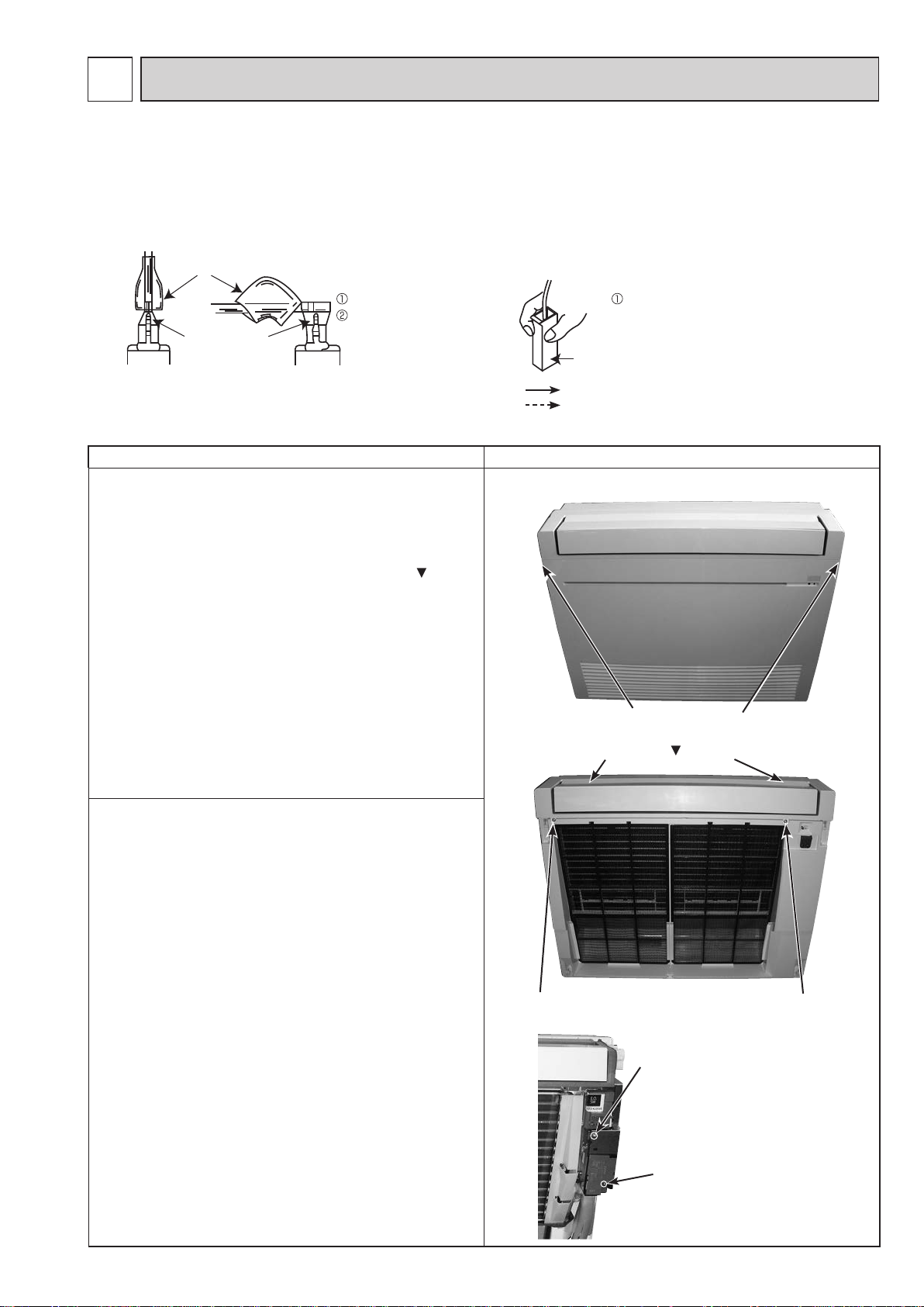
12
OBH843
DISASSEMBLY INSTRUCTIONS
<Detaching method of the terminal with locking mechanism>
The terminal which has the locking mechanism can be detached as shown below.
There are following 2 types of the terminal with locking mechanism.
The terminal without locking mechanism can be detached by pulling it out.
Check the shape of the terminal before detaching.
(1) Slide the sleeve and check if there is a locking lever or not. (2) The terminal with the connector shown below
Sleeve
locking mechanism.
Slide the sleeve.
Pull the terminal while
Locking lever
pushing the locking
lever.
12-1. MFZ-KT25VG MFZ-KT35VG
MFZ-KT50VG MFZ-KT60VG
NOTE: Turn OFF the power supply before disassembly.
OPERATING PROCEDURE PHOTOS/FIGURES
1. Removing the panel
(1) Push down the tabs on the both sides of the unit.
(2) Open the front panel toward you and pull it out
upwards.
(3) Remove the screws of the panel.
(4) Open the horizontal vane (back) and push the
on the top of the panel, and pull the panel toward you.
(5) Lift up the panel and remove it from the unit.
marks
Hold the sleeve, and
pull out the terminal
slowly.
Connector
: Indicates the visible parts in the photos/figures.
: Indicates the invisible parts in the photos/figures.
Photo 1
Tabs of the unit
Photo 2
Push the
marks.
2. Removing the electrical box
(1) Remove the panel. (Refer to section 1.)
(2) Remove the screw of the V.A. clamp cover and
remove the V.A. clamp cover.
(3) Remove the screw of the electrical cover and remove
the electrical cover.
(4) Remove the earth wire connected to the indoor heat
exchanger. (Photo 4)
(5) Remove the screw of the electrical box. (Photo 5)
(6) Disconnect the following connectors on the electronic
control P.C. board.
• Fan motor connector < CN211> (Photo 5)
•
Indoor coil thermistor connector < CN112>
(7) Rotate the display receiver P.C. board holder to the
right side and disconnect the vane motor relay con-
nector. (Photo 6)
(8) Disengage the electrical box from the upper catch
and pull out the electrical box from the box.
(Photo 5)
Screw of the panel
Photo 3
37
Screw of the panel
Screw of the
electrical cover
Screw of the
V.A. clamp cover
Page 38

OPERATING PROCEDURE PHOTOS/FIGURES
OBH843
3. Removing the electronic control P.C. board and
the display receiver P.C. board
(1) Remove the panel. (Refer to section 1.)
(2) Remove the electrical box. (Refer to section 2.)
(3) Remove the earth wire connected to the electronic
control P.C. board.
(4) Disconnect all the connectors on the electronic con-
trol P.C. board.
(5) Pull out the electronic control P.C. board from the
electrical box.
(6) Disengage the catches on the lead guide.
(7) Disengage the display receiver P.C. board holder
from the catch on the electrical box.
(8) Open the display receiver P.C. board holder and pull
out the display receiver P.C. board.
Attaching the connectors
Run the lead wires with the connectors as they were
before the disassembly.
4. Removing the nozzle assembly
(1) Remove the panel. (Refer to section 1.)
(2) Rotate the display receiver P.C. board holder to the
right side and disconnect the vane motor relay con-
nector.
(3) Remove the fixed screws on the both sides of the
nozzle.
(4) Disengage the catches on the nozzle from the box.
(5) Hold the both sides of the nozzle. Rotate the nozzle
toward you around the right and left ribs to remove it.
Photo 4
Photo 5
Earth wire connect to
the heat exchanger
Earth wire
connect to the
indoor electronic
control P.C. board
Indoor coil
thermistor
connector (CN112)
Display receiver
P.C. board
connector (CN1J1)
Photo 7
Photo 8
Catches on the display
receiver P.C. board holder
Catches on
the lead guide
Lamp cover
Display receiver
P.C. board
Vane motor
Connector (CN151)
R32 sensor
(CNSA)
Screw of the
electrical box
Fan motor
connector (CN211)
Photo 6
Vane motor relay
connector
Catch on the display receiver P.C.
board holder and
the electrical box
Display receiver
P.C. board
38
Page 39

How to remove the multi-flow
OBH843
vane and the horizontal vanes
Unit body
(1) Removing the horizontal vane (front/back)
Horizontal vane (back)
Horizontal vane (front)
(1)-1. See the figure below and push to open the indicated
places on the horizontal vanes (between front and back)
with your fingers s
positioned on the back of the horizontal vanes.
(vane shafts on each horizontal vane)
o that you can access 4 vane shafts
Va
ne shafts
Multi-flow vane
(2) Removing the multi-flow vane
(2)-1.Open the horizontal vanes (front and back) by following (1)-1.
Make sure that 3 vane shafts are on the back of the multi-flow vane.
Vane shafts
Multi-flow vane
Top down view from the back of the unit
(1)-2. Insert a tool such as a precision screwdriver
in the opening on the vane shaft and lift the catch
of the vane sha
rom the rib on the horizontal vane. Slide the vane shaft
f
in arrow 2 direction and separate it from the unit body.
ft in arrow 1 direction to detach it
Unit body
Vane shaft
Opening
Rib
Catch
Horizontal vane
(1)-3. Remove the axial rods on the both ends of the
horizontal vane from the unit body.
(2)-2. Insert a tool such as a precision screwdriver in the gap
b
etween multi-flow vane and the vane shaft and lift the catch
of the vane shaft in the arrow 1 direction to detach it from the rib
on the multi-flow vane. Slide the vane shaft in arrow 2 direction
and separate it from the unit body.
Catch
Rib
Multi-flow vane
(2)-3. Remove the axial rod on the one end of the multi-flow
vane from the unit body.
Vane shaft
Unit body
39
Page 40

OPERATING PROCEDURE PHOTOS/FIGURES
OBH843
5. Removing the horizontal vane motor
(1) Remove the panel. (Refer to section 1.)
(2) Remove the screws of the horizontal vane motor sup-
port and pull out the horizontal vane motor support
from the nozzle.
(3) Remove the screws of the horizontal vane motors.
(4) Remove the horizontal vane motors from the horizon-
tal vane motor support.
(5) Disconnect the connectors from the horizontal vane
motor.
Installing the horizontal vane motor
Connect the connectors to the horizontal vane motors
by referring to the colors, red and white, noted on the
vane motor support.
6. Removing the multi-flow vane motor unit
(1) Remove the panel. (Refer to section 1.)
(2) Disconnect the connector from the multi-flow vane
motor unit.
(3) Remove the screws of the multi-flow vane motor unit
and pull out the multi-flow vane motor unit from the
nozzle.
Photo 9
Screws of the nozzle
Catches
Water cover
Photo 10
Catch Catch
Photo 11
Screws of the horizontal
vane motors
Photo 12
Screws of the horizontal
vane motor support
Rib
Screws of the multi-flow vane motor unit
Rib
40
Page 41

OPERATING PROCEDURE PHOTOS/FIGURES
OBH843
7. Removing the line flow fan and the indoor fan
motor
(1) Remove the panel. (Refer to section 1.)
(2) Remove the electrical box. (Refer to section 2.)
(3) Remove the nozzle. (Refer to section 4.)
(4) Disengage the water cover from the catches. (Photo 9)
(5) Remove the screws fixing the motor bed.
(6) Loosen the screw fixing the line flow fan.
(7) Remove the motor bed together with the indoor fan
motor and the motor band.
(8) Disengage the catches on the motor band and remove
the motor band, and pull out the indoor fan motor.
(9) Remove the screws fixing the both sides of the heat
exchanger.
(
10
) Disengage the catch on the right side on the heat
exchanger.
(
11
) Lift the heat exchanger, and pull out the line flow fan
upward.
Photo 16
Photo 13
Screw of the line flow fan
Photo 14
Screws of the motor bed
Photo 17
Screw of the
heat exchanger
Catches of the
heat exchanger
Photo 15
Screws of the
heat exchanger
41
Page 42

OPERATING PROCEDURE PHOTOS/FIGURES
OBH843
8. Removing the R32 sensor
(1) Remove the panel. (Refer to section 1.)
(2) Loosen the screw of the R32 sensor plate, and take
the R32 sensor plate.
(3) Cut the band fixing the lead wire.
(4) Disengage the R32 sensor cover from the R32 sensor
plate.
(5) Disengage the catches to open the R32 sensor cover.
(6) Take the R32 sensor, then disconnect the lead wire.
Photo 20
R32 sensor plate
Band fixing
the lead wire
Photo 18
Screw of the
R32 sensor plate
Photo 21
R32 sensor
Photo 19
R32 sensor cover
R32 sensor plate
Catch
42
Page 43

OBH843
43
Page 44

HEAD OFFICE: TOKYO BUILDING, 2-7-3, MARUNOUCHI, CHIYODA-KU, TOKYO 100-8310, JAPAN
Copyright 2019 MITSUBISHI ELECTRIC CORPORATION
Published: Jun. 2019. No. OBH843
Made in Japan
Specifications are subject to change without notice.
 Loading...