

Mitsubishi Electric MFZ-KA50VA, MFZ-KA35VA, MFZ-KA25VA INSTALLATION MANUAL
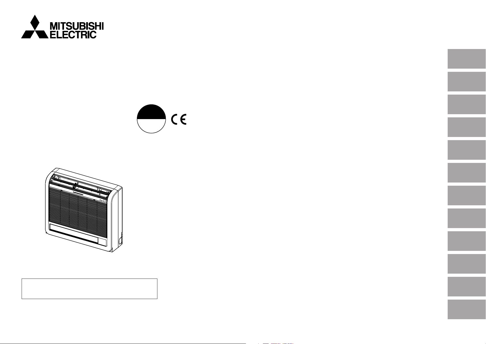
Floor Type Air-Conditioner
HFC
utilized
R410A
English
CONTENTS
MFZ-KA25VA
MFZ-KA35VA
MFZ-KA50VA
[FLARE CONNECTION TYPE]
INSTALLATION MANUAL
1. THE FOLLOWING SHOULD ALWAYS BE OBSERVED FOR
SAFETY ........................................................................................... 2
2. INSTALLATION DIAGRAM & ACCESSORIES ................................ 2
3. SELECTING THE INSTALLATION LOCATION ................................ 3
4. INDOOR UNIT INSTALLATION ....................................................... 4
5. INDOOR/OUTDOOR UNIT CONNECTION FINISHING AND
TEST RUN ....................................................................................... 9
6. FOR MOVEMENT AND MAINTENANCE...................................... 11
Deutsch
Français
Nederlands
Español
Italiano
∂ППЛУИО¿
Português
Dansk
• This manual only describes the installation of indoor unit.
When installing the outdoor unit, refer to the installation manual
of outdoor unit.
FOR INSTALLER
Svenska
Türkçe
Русский
1. THE FOLLOWING SHOULD ALWAYS BE OBSERVED FOR
SAFETY
•
Please provide an exclusive circuit for the air conditioner and do not connect other electrical appliances to it.
• Be sure to read “THE FOLLOWING SHOULD ALWAYS BE OBSERVED FOR SAFETY” before installing
the air conditioner.
• Be sure to observe the cautions specified here as they include important items related to safety.
• The indications and meanings are as follows.
Warning: Could lead to death, serious injury, etc.
Caution: Could lead to serious injury in particular environments when operated incorrectly.
• After reading this manual, be sure to keep it together with the instruction manual in a handy place on
the customer’s site.
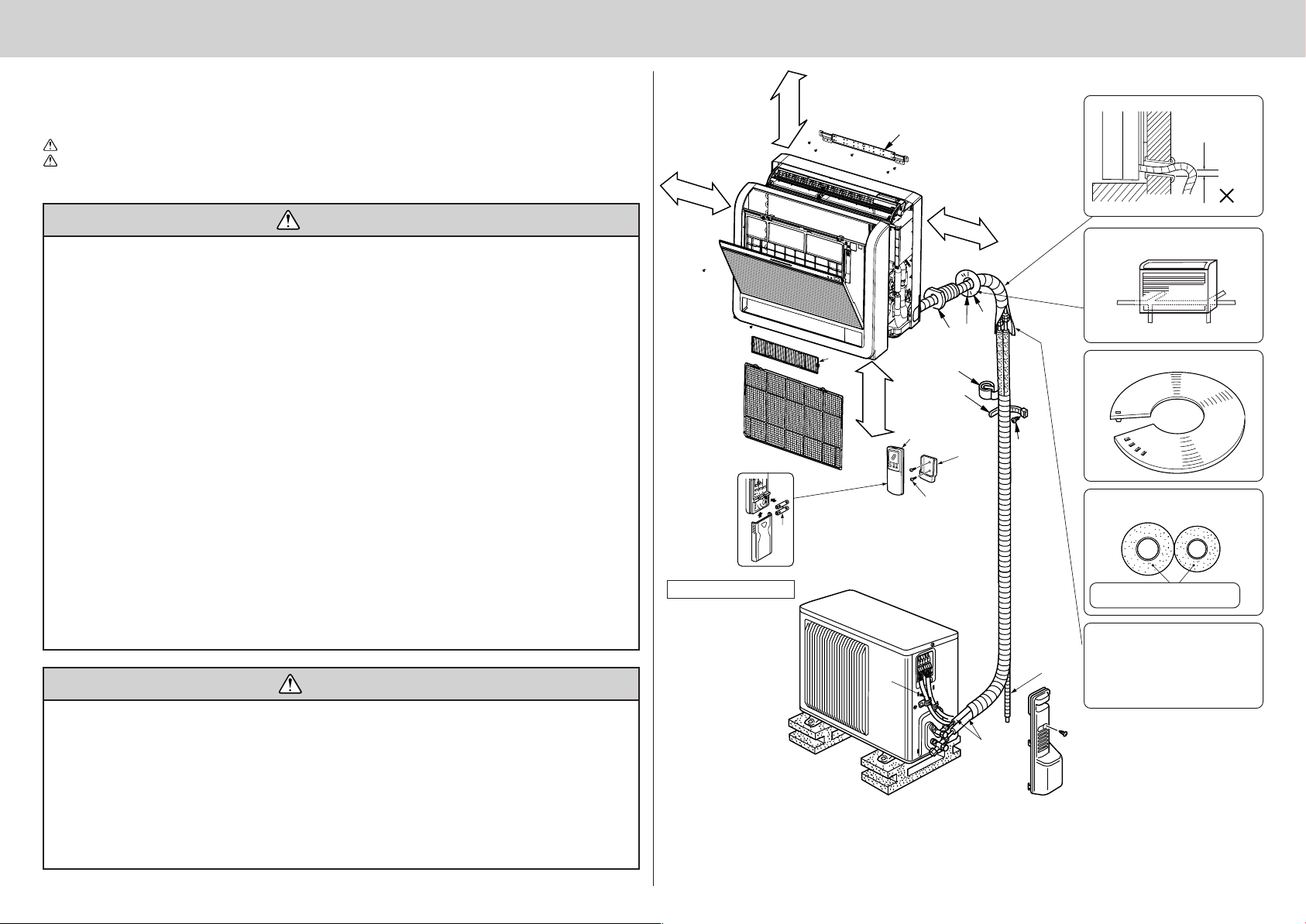
2. INSTALLATION DIAGRAM & ACCESSORIES
100 mm or more
100 mm or more
7
Be careful the
drain hose is not
raised.
Warning
■ Do not install it by yourself (customer).
Incomplete installation could cause injury due to
fire, electric shock, the unit falling or leakage of
water. Consult the dealer from whom you purchased the unit or special installer.
■ Install the unit securely in a place which can
bear the weight of the unit.
When installed in an insufficient strong place, the
unit could fall causing injury.
■ Use the specified wires to connect the indoor
and outdoor units securely and attach the
wires firmly to the terminal block connecting
sections so the stress of the wires is not applied to the sections.
Incomplete connecting and fixing could cause a fire.
■ Do not use intermediate connection of the
power cord or the extension cord and do not
connect many devices to one AC outlet.
It could cause a fire or an electric shock due to
defective contact, defective insulation, exceeding
the permissible current, etc.
■ Check that the refrigerant gas does not leak
after installation has completed.
If refrigerant gas leaks indoors, and comes into
contact with the fire of a fan heater, space heater,
stove, etc., harmful substances will be generated.
■ Perform the installation securely referring to
the installation manual.
Incomplete installation could cause a personal
injury due to fire, electric shock, the unit falling or
leakage of water.
Caution
■ Earth the unit.
Do not connect the earth to a gas pipe, water
pipe, lightning rod or telephone earth. Defective
earthing could cause an electric shock.
■ Do not install the unit in a place where an inflammable gas leaks.
If gas leak and accumulate in the area surrounding the unit, it could cause an explosion.
■ Install an earth leakage breaker depending on
the installation place (Where it is humid).
If an earth leakage breaker is not installed, it could
cause an electric shock.
■ Perform electrical work according to the installation manual and be sure to use an exclusive circuit.
If the capacity of the power circuit is insufficient
or there is incomplete electrical work, it could
result in a fire or an electric shock.
■ Attach the electrical part cover to the indoor
unit and the service panel to the outdoor unit
securely.
If the electrical part cover in the indoor unit and/
or the service panel in the outdoor unit are not
attached securely, it could result in a fire or an
electric shock due to dust, water, etc.
■ Be sure to use the part provided or specified
parts for the installation work.
The use of defective parts could cause an injury
or leakage of water due to a fire, an electric shock,
the unit falling, etc.
■ Be sure to cut off the main power in case of
setting up the indoor electronic control P.C.
board or wiring works.
It could cause an electric shock.
■ The appliance shall be installed in accordance
with national wiring regulations.
■ When installing or relocating the unit, make
sure that no substance other than the specified refrigerant (R410A) enters the refrigerant
circuit.
Any presence of foreign substance such as air
can cause abnormal pressure rise or an explosion.
■ Perform the drainage/piping work securely
according to the installation manual.
If there is a defect in the drainage/piping work,
water could drop from the unit and household
goods could be wet and damaged.
■ Fasten a flare nut with a torque wrench as
specified in this manual.
When fastened too tight, a flare nut may broken
after a long period and cause a leakage of refrigerant.
SUZ-KA25/35 VA (H)
100 mm or more
D
H
C
C
150 mm or below
from the floor
6
A
G
E
B
2
3
F
I
B
Piping can be directed towards rear,
right, downward, left or left-rear
directions.
Left
Left-Downward
Separate the 2 connecting pipes and apply insulation individually.
8 mm thickness thermal insulation plastic
When the piping is to be attached to a
wall containing metals (tin plated) or
metal netting, use a chemically treated
wooden piece 20 mm or thicker between
the wall and the piping or wrap 7 to 8
turns of insulation vinyl tape around the
piping.
Left-rear
Lock the catch.
Rear
Downward
2
3. SELECTING THE INSTALLATION LOCATION
ACCESSORIES
Check the following parts before installation.
<Indoor unit>
1 Drain hose 1
2 Remote controller holder 1
3 Fixing screw for 2 3.5 × 16 mm (Black) 2
4 Pipe cover 1
5 Band 2
6 Battery (AAA) for remote controller 2
7 Indoor unit mounting bracket 1
8 Fixing screw for 7 4 × 25 mm 5
9 Wood screw for the indoor unit fixation 4
0 Washer of 9 4
A Felt tape (Used for left or left-rear piping) 1
B Wireless remote controller 1
C Air cleaning filter 1
PART TO BE PROVIDED AT YOUR SIDE
Optional extension pipe
Indoor/outdoor unit connecting wire
A
(4-core 1.5 mm
B Extension pipe 1
C Wall hole sleeve 1
D Wall hole cover 1
Pipe fixing band
E
(The quantity depends on the pipe length.)
Fixing screw for E 4 × 20 mm (The quantity
F
depends on the pipe length.)
G Piping tape 1
H Putty 1
Drain hose (or soft PVC. hose, 15 mm inner dia.
I
or hard PVC pipe VP16)
J Refrigeration oil 1
2
)
FLARED CONNECTIONS
• This unit has flared connections on both indoor and outdoor sides.
• Refrigerant pipes are used to connect the indoor and outdoor units as shown in the figure below.
• Insulate both refrigerant and drain piping completely to prevent condensation.
PIPING PREPARATION
1 Table below shows the specifications of pipes commercially available.
Pipe Outside diameter Insulation thickness Insulation material
For liquid 6.35 mm 8 mm
For gas
KA25/35 9.52 mm 8 mm
KA50 12.7 mm 8 mm
Heat resisting foam plastic
0.045 specific gravity
1
2 to 5
2 to 5
1 or 2
3-1 INDOOR UNIT
• Where airflow is not blocked.
• Where cool air spreads over the entire room.
• Maximum refrigerant piping length between indoor unit and outdoor unit is 20 m (for 25/35) 30 m (for 50) and
the difference of height of both units is 12 m (for 25/35) 15 m (for 50).
• Rigid wall without vibration.
• Where it is not exposed to direct sunshine.
• Where easily drained.
• At a distance 1 m or more away from your TV and radio. Operation of the air conditioner may interfere with
radio or TV reception in areas where reception is weak. An amplifier may be required for the affected device.
• In a place as far away as possible from fluorescent and incandescent lights (so the infrared remote control
can operate the air conditioner normally).
• Where the air filter can be removed and replaced easily.
3-2 WIRELESS REMOTE CONTROLLER MOUNTING
• Place of mounting
- Where it is easy to operate and easily visible.
- Where children cannot touch.
• Mounting
Select a position about 1.2 m above the floor, check that signals from the controller are surely received by
the indoor unit from that position (‘beep’ or ‘beep-beep’ receiving tone sounds), attach remote controller
holder 3 to a pillar or wall, then set the wireless remote controller 6.
In rooms where inverter type fluorescent lamps are used, the signal from the wireless remote controller may
not be received.
• Use a copper pipe or a copper-alloy seamless pipe with a thickness of 0.8 mm (for ø6.35 and ø9.52) or 1.0
mm (for ø12.7). Never use any pipe with a thickness less than 0.8 mm (for ø6.35 and ø9.52) or 1.0 mm (for
ø12.7), as the pressure resistance is insufficient.
2 Ensure that the 2 refrigerant pipes are well insulated to prevent condensation.
3 Refrigerant pipe bending radius must be 100 mm or more.
Caution:
Be sure to use the insulation of specified thickness. Excessive thickness may cause incorrect installation of the indoor unit and lack of thickness may cause dew drippage.
3
4. INDOOR UNIT INSTALLATION
674
333
363
210
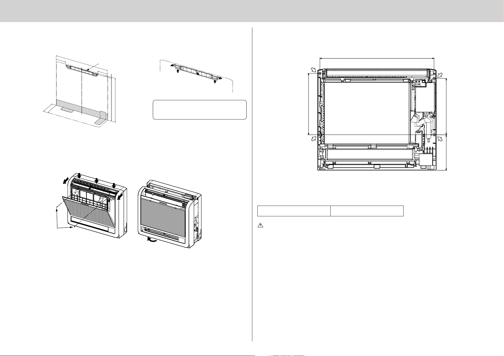
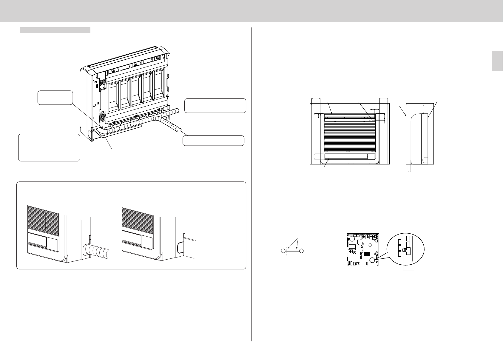
4-1 INDOOR UNIT MOUNTING BRACKET INSTALLATION
• Install the bracket firmly to the wall structure (stud, etc.).
• Use a level to install the mounting bracket horizontally.
• Install the indoor unit 150 mm or below from the floor.
131
200
(700)
Indoor unit mounting bracket 7
131
14
586
(600)
To prevent the indoor unit mounting bracket 7 from vibrating slightly, be sure to fasten the bracket at the holes
indicated by b. In addition, fasten the bracket at the holes
indicated by f if possible.
4-2 INDOOR UNIT PREPARATION
• Press the 2 positions indicated by the arrows e and open the front grille.
• Open the front grille and remove the two screws.
• Open the horizontal vane for the upper air outlet, push the top of the front panel in three locations, and then
pull the top of the grille away from the indoor unit.
• Lift up the front grille to remove it.
4-3 INDOOR UNIT INSTALLATION
• Hook the top of the indoor unit on the indoor unit mounting bracket 7.
• Use the included wood screws 9 and washer 0, and fasten the indoor unit at 2 locations(e) each at the top
and the middle of the unit.
4-4 CONNECTING WIRE SPECIFICATIONS
• Use special room air conditioning circuit.
Screws
Indoor/outdoor unit connecting Cable 4-core 1.5 mm2, in conformity
wire Specification with Design 245 IEC 57.
Warning:
Never cut the indoor and outdoor unit connecting wire and connect it to other wires. It may cause a fire.
4
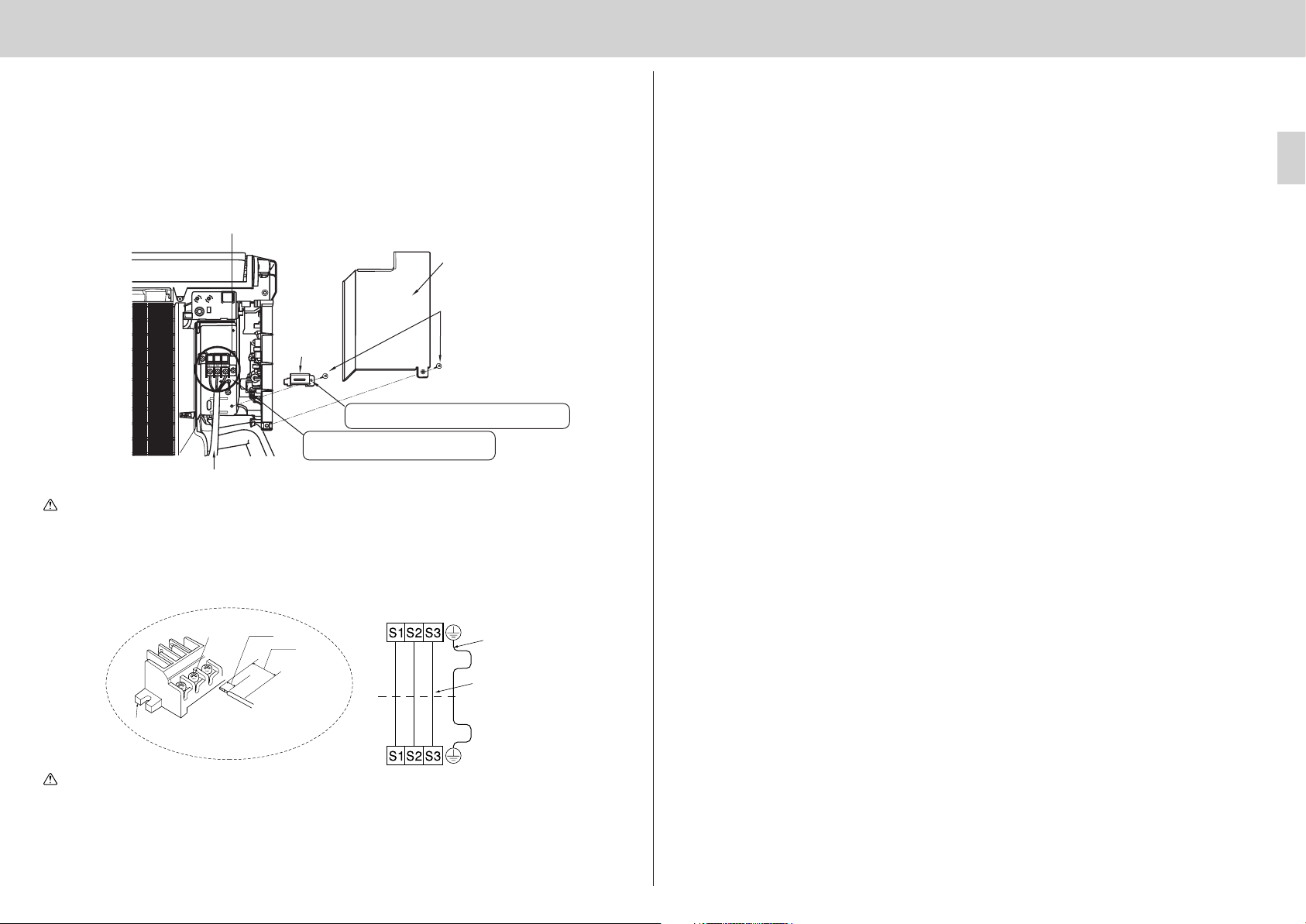
4-5 INDOOR AND OUTDOOR CONNECTING WIRE CONNECTION
You can connect indoor/outdoor lead wire without removing the front panel.
1 Open the front panel.
2 Remove two screws holding the cabinet, then remove the cabinet.
3 Remove one screw holding the electrical cover, then remove the cover.
4 Remove one screw holding the cord clamp, then remove the clamp.
5 Pass the indoor/outdoor unit connecting wire and fix the wire to the terminal block.
6 Secure the indoor/outdoor unit connecting wire and the earth wire with the cord clamp.
7 Re-install the fixture and electrical cover securely.
Indoor
terminal block
ELECTRICAL COVER
4-6 AUTO RESTART FUNCTION
• These models are equipped with an auto restart function. If you do not want to use this function, please
consult the service representative because the setting of the unit needs to be changed.
• When the indoor unit is controlled with the remote controller, the operation mode, the set temperature, and
the fan speed are memorized by the indoor electronic control P.C. board. The auto restart function sets to
work the moment the power has restored after power failure, then, the unit will restart automatically. If the unit
is operated in “AUTO” mode before power failure, the operation mode (COOL, DRY or HEAT) is not stored in
the memory. When the main power is turned on, the unit decides the operation mode by the initial room
temperature at restart and starts operation again.
Operation
1 If the main power has been cut, the operation settings remain.
2 When three minutes have passed after power was restored, the unit will restart automatically according to
the memory.
Fixing screw
Cord clamp
Never fail to hook the right claw on the VA clamp to
secure indoor/outdoor unit connecting wire A.
Securely push the wire into the terminal block
until no part of its core is appeared.
Indoor/outdoor unit connecting wire A
Warning:
• Use the indoor/outdoor unit connecting wire that meets the Standards to connect the indoor and
outdoor units and fix the wire to the terminal block securely so that no external force is conveyed to
the connecting section of the terminal block. Incomplete connection or fixing of the wire could result
in a fire.
• Attach the cord clamp securely. If it is attached incorrectly, it could result in a fire or an electric shock
due to dust, water, etc.
Indoor terminal block
Earth wire
(green/yellow)
Indoor/outdoor unit
connecting wire A
4-core 1.5 mm
2
Terminal block
Loosen terminal
screw.
Lead wire
15 mm
35 mm
Notes:
• The operation settings are memorized when 10 seconds have passed after the remote controller was operated.
• If the main power is turned off or a power failure occurs while AUTO START/STOP timer is active, the timer
setting is cancelled. As these models are equipped with an auto restart function, the air conditioner starts
operating with timer cancelled at the same time that power is restored.
• If the unit has been off with the remote controller before power failure, the auto restart function does not work
as the power button of the remote controller is off.
• To prevent breaker off due to the rush of starting current, systematize other home appliances not to turn on
at the same time.
Caution:
<Connection details>
Outdoor terminal block
• Be careful not to make mis-wiring.
• Firmly tighten the terminal screws to prevent them from loosening.
• After tightening, pull the wires lightly to confirm that they do not move.
• If the connecting wire is incorrectly connected to the terminal block, the unit does not operate normally.
• If an earth is incorrect, it may cause an electric shock.
• Make earth wire a little longer than the others. (more than 55 mm)
5
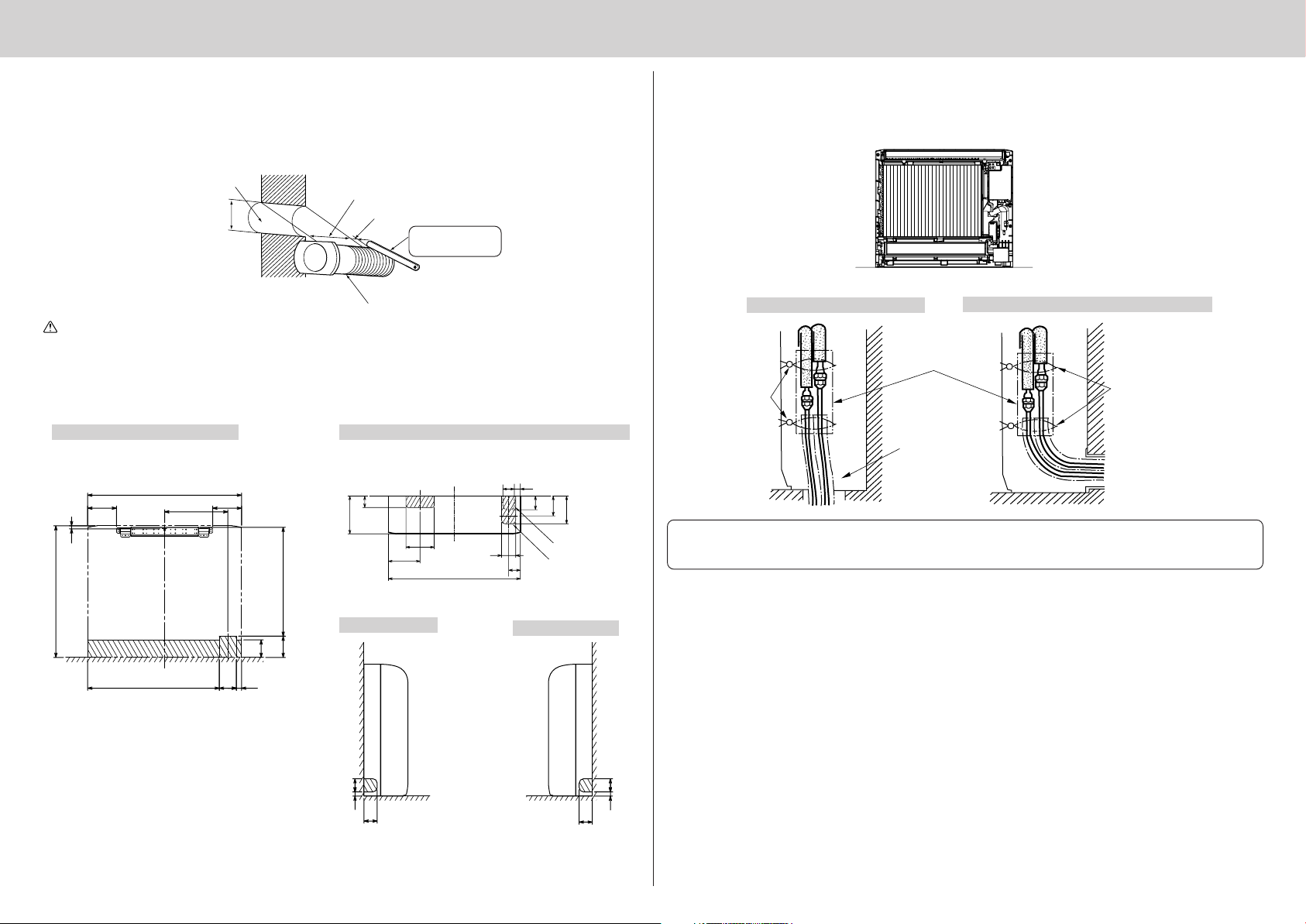
4-7 MAKING HOLES IN THE WALL AND FLOOR
MAKING HOLES
1 Make ø65 mm holes (ø75 mm for KA50) that are approximately 5–7 mm deep and angled slightly downward
outward from the room.
2 Insert the wall hole sleeves C into the holes.
4-8 PIPING INSTALLATION
CONNECTING PIPE INSTALLATION
• Install the connecting pipes so that the piping can move slightly to the front, back, left, and right.
Wall hole
65 mm dia.
(ø75 mm for KA50)
(Indoor side)
(Wall hole cross section)
Wall thickness
One scale
Wall hole sleeve C
Cut with 1 extra
scale length.
Caution:
Be sure to use the wall hole sleeves
CC
C. Otherwise, the indoor/outdoor unit connecting wires may con-
CC
tact a metal object in the wall or, in the case of hollow walls, small rodents may gnaw on the wires,
resulting in a very dangerous situation.
DETERMINING HOLE POSITIONS
• The areas where the piping can be routed are indicated with oblique lines in the figure.
FOR REAR OR LEFT-REAR PIPING
(The following figure is a front view of the indoor
unit installation location.)
131
14
600
700
288
131
80
496
97
FOR RIGHT DOWNWARD OR LEFT DOWNWARD PIPING
(The following figure is a view of the bottom of the indoor
unit from above.)
61
31
60
200
150
168
700
FOR LEFT PIPING
73
75
62
FOR RIGHT PIPING
105
147
When the unit is
installed on the wall.
When the unit is
installed on the floor.
FOR RIGHT DOWNWARD PIPING
Pipe covers 4
Bands 5
Remove the cover.
FOR PIPING OTHER THAN RIGHT DOWNWARD
Bands 5
• Be sure to insulate the connecting pipes and place them near the rear of the indoor unit so that they do not
contact the front panel.
• Be careful not to crush the connecting pipes when bending them.
599
2378
SEALING THE HOLES
• Use putty or a caulking compound to seal the holes.
60
19
60
19 60
60
6
FOR LEFT OR LEFT-REAR PIPING
Bundle the connecting pipes and drain hose together, and then wrap them in felt tape B.
Make sure that the
drain hose is not
routed upward.
Start wrapping the piping tape D
around the pipes and hose 10 mm
inside the indoor unit.
4-9 EMBEDDING THE INDOOR UNIT IN A WALL
• When installing a grating, use a grating with narrow upper and lower horizontal bars so that the airflow from
the upper and lower air outlets does not contact the bars. If the horizontal bars will block the lower air outlet,
use a stand, etc., to adjust the height of the indoor unit. If the upper or lower air outlet is blocked, the air
conditioner will not be able to cool or warm the room well.
• Do not block the receiver with the grating. Otherwise, the grating will interfere with the remote controller
signal and significantly reduce the distance and area (angle) from which the signals can be received.
• Use a grating with vertical bars, etc., that has at least 75% open area. If the grating has horizontal bars or if
the open area is less than 75%, performance could be reduced.
• When the indoor unit is embedded in a wall (built-in), the time it takes for the room temperature to reach the
set temperature will increase.
100 or more
52
Upper air outlet
Receiver
100 or more
6026
6514
Grating
100 or
more
Indoor unit
Wrap the felt tape B tightly around
the pipes and hose starting near
where the pipes and hose are routed
from the indoor unit. (The overlap
width of the felt tape B should not be
more than 1/2 of the tape width.)
Felt tape B
Fasten the end of the felt tape B with
a bandage stopper.
Cut and use the lower side panels on the left and right sides of the indoor unit as shown below.
Smooth the cut edges of the side panels so that they will not damage the insulation coating.
• For left or right piping
• Installing flush against a wall with molding
Molding
Cut the lower side panels to match the height of the molding.
475
65
Lower air outlet
35 or more
EMBEDDED INDOOR UNIT SETTING (MUST BE PERFORMED)
• When embedding the indoor unit in a wall, restrict the movement of the horizontal vane for the upper air outlet
so that it only operates horizontally.
• If this setting is not performed, heat will build up in the wall and the room will not be cooled or warmed
properly.
• Cut the wires on the left and right sides of JR24 using a pair of nippers, etc., as shown below.
Cut
Cut the wires on both ends.
Control board
JRFBL
JR24
Cut the JR24 wires.
7
2
3
3
3
3
3
3
3
2
2
2
4
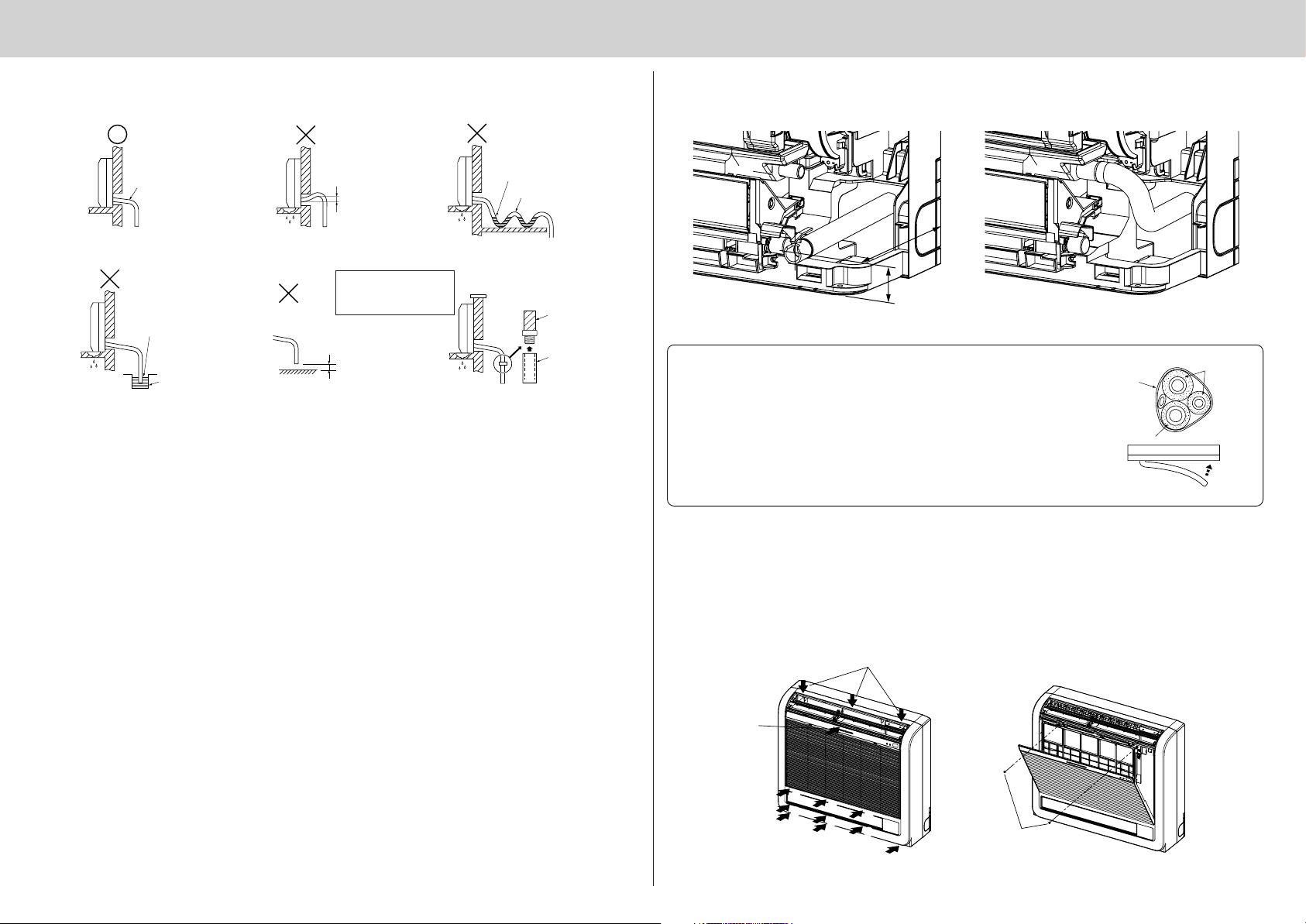
4-10 DRAIN PIPING
• Be sure to route the drain piping slightly downward so that the drain water flows easily. (Fig. 1)
Do not route the drain piping as shown in Fig. 2 to 5.
• When routing the drain piping, make sure that the drain hose 1 is routed as shown. (Fig. 7)
• Insert the drain hose all the way to the base of the drain pan. (Fig. 8)
Make sure that the drain hose is securely caught on the projection in the hole in the drain pan.
Sloping
downward
No upward
slope
Accumulated
drain water
Air
Fig. 1 Fig. 2 Fig. 3
If the drain hose is routed
indoors, be sure to wrap it
End of drain
hose is
immersed in
water.
Fig. 4
Drainage
channel
in commercially-available
insulation.
50 mm or
less from
ground
Fig. 5
Fig. 6
Drain hose
Flexible PVC
hose (inner
diameter: 15 mm)
or rigid PVC pipe
(VP-16)
• If the drain hose is too short, refer to Fig. 6 to extend the length of the hose.
• If the indoor unit is installed in a high location such as a high-rise apartment, strong winds may cause the
drain water to flow back through the drain hose and leak from the unit. If necessary, contact your nearest
Mitsubishi Electric representative for the optional parts to prevent this problem.
• If the drain hose is routed indoors, be sure to wrap it in commercially-available insulation.
• If embedding the piping in a wall, remove the lower side panels on the left and right sides of the indoor unit
when connecting the drain hose.
• Do not connect the drain piping directly to a septic tank, sewage tank, etc., where ammonia gases or hydrogen sulfide are produced.
• If there is slack in the drain hose or the end of the drain hose is raised up, the drain water may not flow
smoothly and some drain water may collect in the hose. This can lead to a strange sound (burbling) being
produced during strong winds or when a ventilation fan, etc., is used in a residence that is well-sealed. If
necessary, contact your nearest Mitsubishi Electric representative for the optional parts to prevent this problem.
200
50
Fig. 7 Fig. 8
• Route the drain hose diagonally below the connecting pipes.
• Make sure that the drain hose is not routed upward and that there are no
waves in the hose.
Piping tape
Refrigerant
piping
• Do not pull the drain hose, and then wrap tape around it.
• Route the piping so that it does not project past the rear of the indoor unit.
(Refer to the figure to the right.)
Drain hose
Piping bent
outward
Push
4-11 FRONT PANEL INSTALLATION
1 Open the horizontal vane for the upper air outlet.
2 Fit the front panel onto the indoor unit from the front, and then push the upper and lower areas that are
marked with arrows.
3 Push the areas below the upper air outlet and the areas above and below the lower air outlet that are marked
with arrows.
4 After installing the front panel, install the 2 screws below the upper air outlet.
8
 Loading...