

Page 1

General-Purpose AC Servo
MELSERVO-J4 Servo amplifier
INSTRUCTION MANUAL TROUBLE SHOOTING
Page 2
Safety Instructions
Please read the instructions carefully before using the equipment.
To use the equipment correctly, do not attempt to install, operate, maintain, or inspect the equipment until
you have read through this Instruction Manual, Installation guide, and appended documents carefully. Do not
use the equipment until you have a full knowledge of the equipment, safety information and instructions.
In this Instruction Manual, the safety instruction levels are classified into "WARNING" and "CAUTION".
WARNING
CAUTION
Note that the CAUTION level may lead to a serious consequence according to conditions.
Please follow the instructions of both levels because they are important to personnel safety.
What must not be done and what must be done are indicated by the following diagrammatic symbols.
Indicates that incorrect handling may cause hazardous conditions,
resulting in death or severe injury.
Indicates that incorrect handling may cause hazardous conditions,
resulting in medium or slight injury to personnel or may cause physical
damage.
Indicates what must not be done. For example, "No Fire" is indicated by .
Indicates what must be done. For example, grounding is indicated by .
In this Instruction Manual, instructions at a lower level than the above, instructions for other functions, and so
on are classified into "POINT".
After reading this Instruction Manual, keep it accessible to the operator.
A - 1
Page 3
1. To prevent electric shock, note the following
WARNING
Before wiring or inspection, turn off the power and wait for 15 minutes or more until the charge lamp
turns off. Then, confirm that the voltage between P+ and N- is safe with a voltage tester and others.
Otherwise, an electric shock may occur. In addition, when confirming whether the charge la mp is off or
not, always confirm it from the front of the servo amplifier.
Do not operate switches with wet hands. Otherwise, it may cause an electric shock.
2. To prevent fire, note the following
CAUTION
When you use a MR-J4 multi-axis servo amplifier, connecting an encoder for different axis to the CN2A,
CN2B, or CN2C connector may cause a fire.
3. To prevent injury, note the following
CAUTION
The servo amplifier heat sink, regenerative resistor, servo motor, etc. may be hot while power is on or for
some time after power-off. Take safety measures, e.g. provide covers, to prevent accidental contact of
hands and parts (cables, etc.) with them.
4. Additional instructions
The following instructions should also be fully noted. Incorrect handling may cause a malfunction, injury,
electric shock, etc.
(1) Wiring
CAUTION
Wire the equipment correctly and securely. Otherwise, the servo motor may operate unexpectedly.
To avoid a malfunction, connect the wires to the correct phase terminals (U, V, and W) of the servo
amplifier and servo motor.
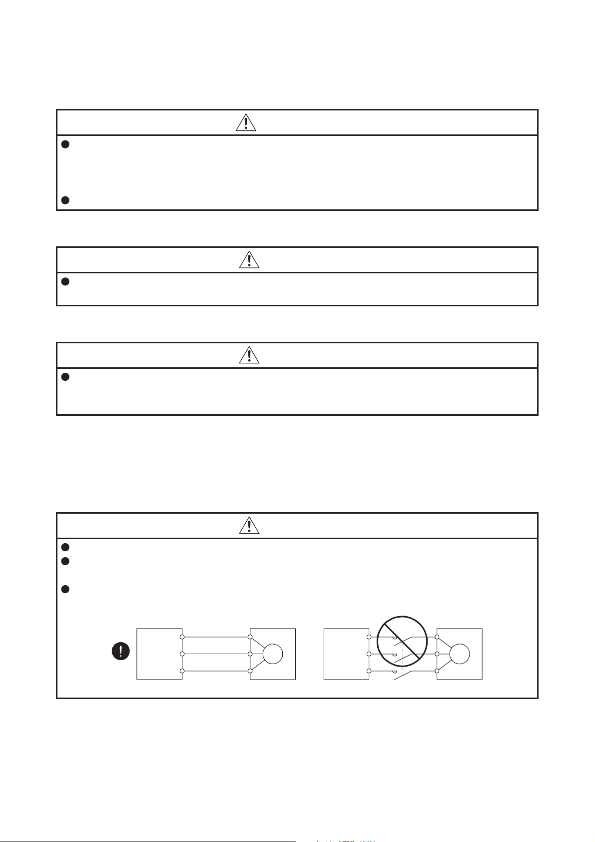
Connect the servo amplifier power output (U, V, and W) to the servo motor power input (U, V, and W)
directly. Do not let a magnetic contactor, etc. intervene. Otherwise, it may cause a malfunction.
Servo amplifier
U
V
W
Servo motor
U
V
W
Servo motorServo amplifier
U
M
V
W
U
V
M
W
A - 2
Page 4
(2) Usage
CAUTION
Before resetting an alarm, make sure that the run signal of the servo amplifier is off in order to prevent a
sudden restart. Otherwise, it may cause an accident.
Use the servo amplifier with the specified servo motor.
(3) Corrective actions
CAUTION
When it is assumed that a hazardous condition may occur due to a power failure or product malfunction,
use a servo motor with an electromagnetic brake or external brake to prevent the condition.
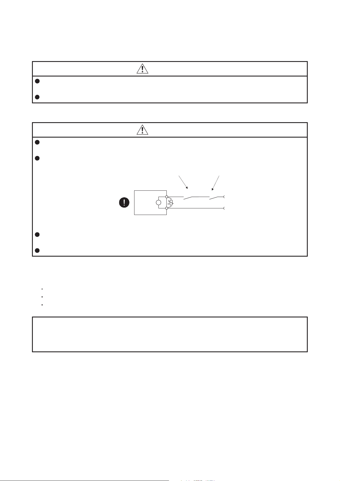
Configure an electromagnetic brake circuit so that it is activated also by an external EMG stop switch.
Contacts must be opened when CALM (Common
malfunction) or MBR (Electromagnetic brake
interlock) turns off.
Contacts must be opened
with the EMG stop switch.
Servo motor
B
Electromagnetic brake
When any alarm has occurred, eliminate its cause, ensure safety, and deactivate the alarm before
restarting operation.
Provide an adequate protection to prevent unexpected restart after an instantaneous power failure.
<<About the manual>>
This Instruction Manual covers the following models.
MR-J4-_A
MR-J4-_B
MR-J4W_-_B
The symbols in the target column mean as follows.
MR-J4-_A: [A]
MR-J4-_B: [B]
MR-J4W_-_B: [WB]
RA
24 V DC
A - 3
Page 5

MEMO
A - 4
Page 6

CONTENTS
1. TROUBLESHOOTING 1- 1 to 1-54
1.1 Alarm and warning list........................................................................................................................ 1- 1
1.2 Remedies for alarms..........................................................................................................................1- 5
1.3 Remedies for warnings.....................................................................................................................1-44
APPENDIX App.- 1 to App.- 1
App. 1 Detection points of [AL. 25], [AL. 92], and [AL. 9F].................................................................App.- 1
1
Page 7

MEMO
2
Page 8
1. TROUBLESHOOTING
1. TROUBLESHOOTING
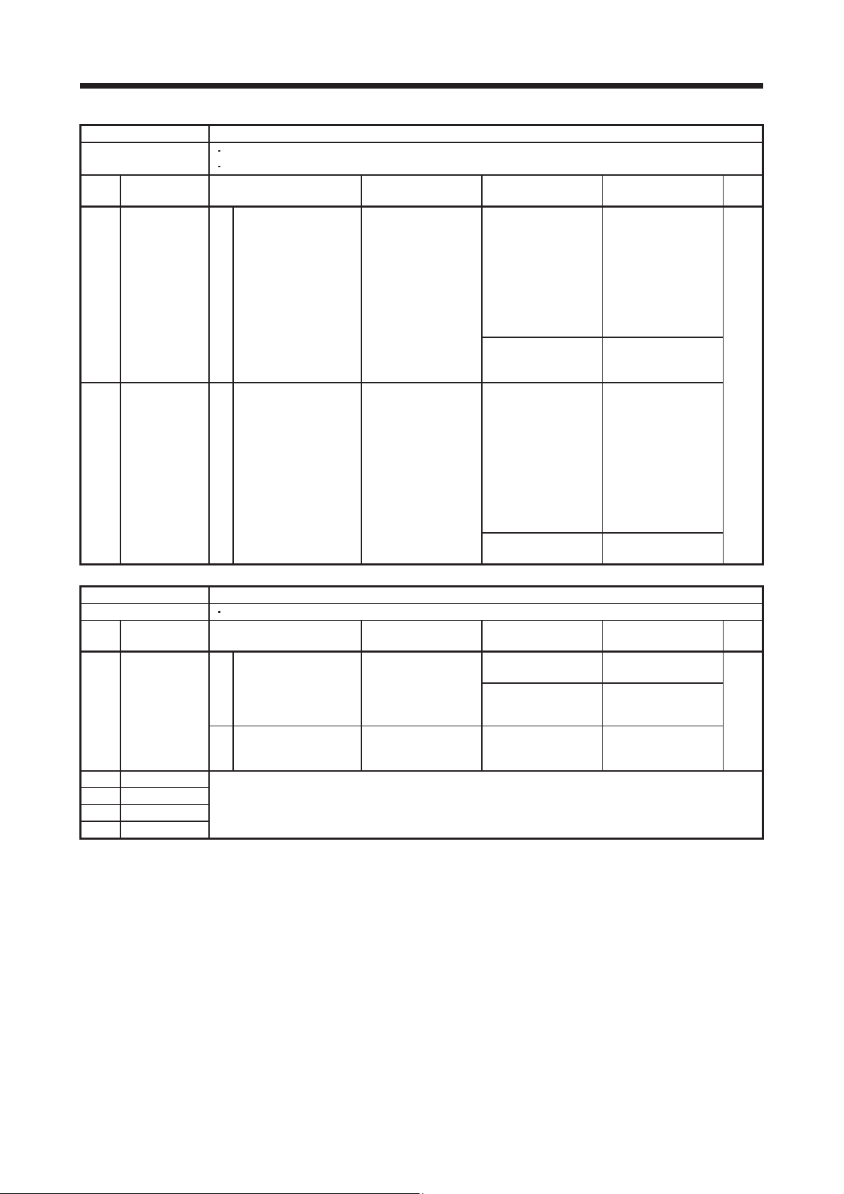
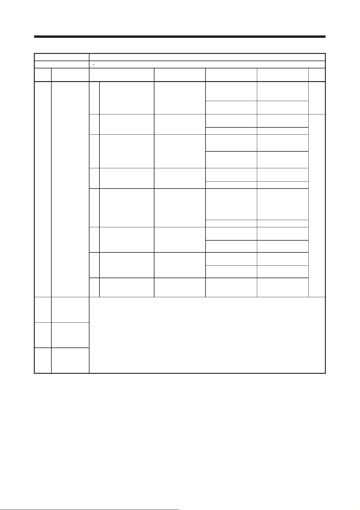
1.1 Alarm and warning list When an error occurs during operation, the corresponding alarm or warning is displayed. If any alarm or
warning has occurred, refer to section 1.2 and take the appropriate action. When an alarm occurs, ALM
(Malfunction) will turn off.
No. Name
Alarm
10 Undervoltage 10.1 Voltage drop in the control power
10.2 Voltage drop in the main circuit power
11 Switch setting error 11.1 Axis number setting error
11.2 Disabling control axis setting error
12 Memory error 1 (RAM) 12.1 RAM error 1
12.2 RAM error 2
12.3 RAM error 3
12.4 RAM error 4
12.5 RAM error 5
13 Clock error 13.1 Clock error 1
13.2 Clock error 2
14 Control process error 14.1 Control process error 1
14.2 Control process error 2
14.3 Control process error 3
14.4 Control process error 4
14.5 Control process error 5
14.6 Control process error 6
14.7 Control process error 7
14.8 Control process error 8
14.9 Control process error 9
14.A Control process error 10
15 Memory error 2 (EEP-ROM) 15.1 EEP-ROM error at power on
15.2 EEP-ROM error during operation
16 16.1 Encoder initial communication - Receive data error 1
16.3 Encoder initial communication - Receive data error 3
16.5 Encoder initial communication - Transmission data error 1
16.6 Encoder initial communication - Transmission data error 2
16.7 Encoder initial communication - Transmission data error 3
16.A Encoder initial communication - Process error 1
16.B Encoder initial communication - Process error 2
16.C Encoder initial communication - Process error 3
16.D Encoder initial communication - Process error 4
16.E Encoder initial communication - Process error 5
16.F Encoder initial communication - Process error 6
17 Board error 17.1 Board error 1
17.3 Board error 2
17.4 Board error 3
17.5 Board error 4
17.6 Board error 5
19 Memory error 3 (Flash-ROM) 19.1 Flash-ROM error 1
19.2 Flash-ROM error 2
1A Servo motor combination error 1A.1 Servo motor combination error
1A.2 Servo motor control mode combination error
1E Encoder initial communication
1F Encoder initial communication
Encoder initial communication
error 1
error 2
error 3
Detail
display
16.2 Encoder initial communication - Receive data error 2
1E.1 Encoder malfunction
1F.1 Incompatible encoder
Detail name
1 - 1
Page 9
1. TROUBLESHOOTING
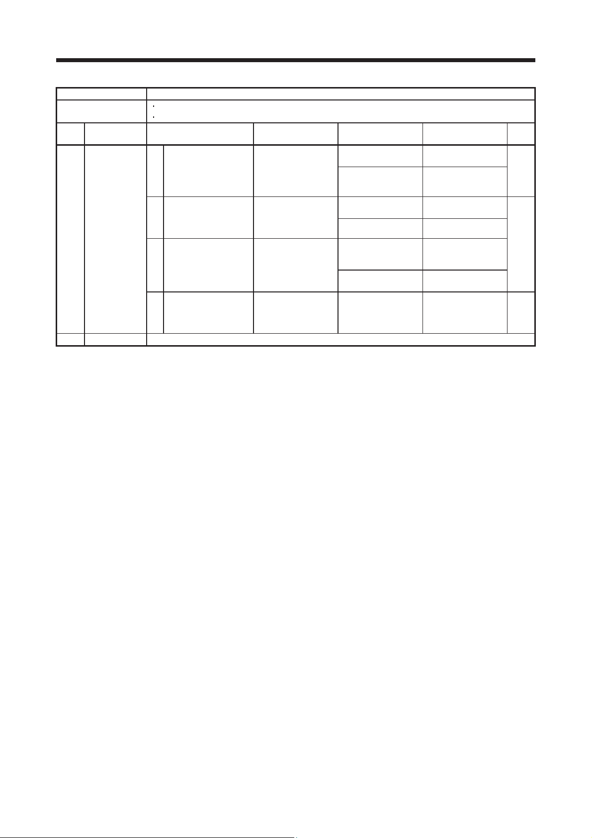
No. Name
Alarm
20 20.1 Encoder normal communication - Receive data error 1
Encoder normal communication
error 1
20.3 Encoder normal communication - Receive data error 3
20.5 Encoder normal communication - Transmission data error 1
20.6 Encoder normal communication - Transmission data error 2
20.7 Encoder normal communication - Transmission data error 3
20.9 Encoder normal communication - Receive data error 4
20.A Encoder normal communication - Receive data error 5
21 21.1 Encoder data error 1
21.3 Encoder data waveform error
21.4 Encoder non-signal error
21.5 Encoder hardware error 1
21.6 Encoder hardware error 2
21.9 Encoder data error 2
24 Main circuit error 24.1 Ground fault detected by hardware detection circuit
24.2 Ground fault detected by software detection function
25 Absolute position erased 25.1 Servo motor encoder - Absolute position erased
27 27.1 Magnetic pole detection - Abnormal termination
27.3 Magnetic pole detection - Limit switch error
27.4 Magnetic pole detection - Estimated error
27.5 Magnetic pole detection - Position deviation error
27.6 Magnetic pole detection - Speed deviation error
27.7 Magnetic pole detection - Current error
28 Linear encoder error 2 28.1 Linear encoder - Environment error
2A Linear encoder error 1 2A.1 Linear encoder error 1-1
2A.2 Linear encoder error 1-2
2A.3 Linear encoder error 1-3
2A.4 Linear encoder error 1-4
2A.5 Linear encoder error 1-5
2A.6 Linear encoder error 1-6
2A.7 Linear encoder error 1-7
2A.8 Linear encoder error 1-8
2B Encoder counter error 2B.1 Encoder counter error 1
2B.2 Encoder counter error 2
30 Regenerative error 30.1 Regeneration heat error
30.2 Regeneration signal error
30.3 Regeneration feedback signal error
31 Overspeed 31.1 Abnormal motor speed
32 Overcurrent 32.1 Overcurrent detected at hardware detection circuit (during operation)
32.2 Overcurrent detected at software detection function (during operation)
32.3 Overcurrent detected at hardware detection circuit (during a stop)
32.4 Overcurrent detected at software detection function (during a stop)
33 Overvoltage 33.1 Main circuit voltage error
34 SSCNET receive error 1 34.1 SSCNET receive data error
34.2 SSCNET connector connection error
34.3 SSCNET communication data error
34.4 Hardware error signal detection
35 Command frequency error 35.1 Command frequency error
36 SSCNET receive error 2 36.1 Continuous communication data error
37 Parameter error 37.1 Parameter setting range error
37.2 Parameter combination error
3A Inrush current suppression circuit
3E Operation mode error 3E.1 Operation mode error
Encoder normal communication
error 2
Initial magnetic pole detection
error
error
Detail
display
20.2 Encoder normal communication - Receive data error 2
21.2 Encoder data update error
27.2 Magnetic pole detection - Time out error
3A.1 Inrush current suppression circuit error
Detail name
1 - 2
Page 10
1. TROUBLESHOOTING
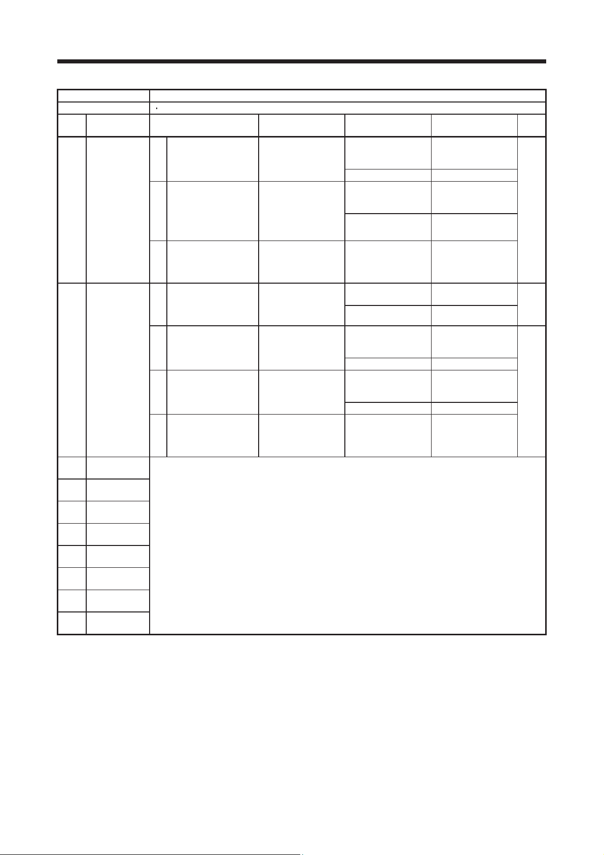
No. Name
Alarm
42 Servo control error 42.1 Servo control error by position deviation
42.2 Servo control error by speed deviation
42.3 Servo control error by torque/thrust deviation
45 Main circuit device overheat 45.1 Main circuit device overheat error
46 Servo motor overheat 46.1 Abnormal temperature of servo motor 1
46.2 Abnormal temperature of servo motor 2
46.3 Thermistor disconnected
46.5 Abnormal temperature of servo motor 3
46.6 Abnormal temperature of servo motor 4
47 Cooling fan error 47.1 Cooling fan stop error
47.2 Cooling fan speed reduction error
50 Overload 1 50.1 Thermal overload error 1 during operation
50.2 Thermal overload error 2 during operation
50.3 Thermal overload error 4 during operation
50.4 Thermal overload error 1 during a stop
50.5 Thermal overload error 2 during a stop
50.6 Thermal overload error 4 during a stop
51 Overload 2 51.1 Thermal overload error 3 during operation
51.2 Thermal overload error 3 during a stop
52 Error excessive 52.1 Excess droop pulse 1
52.3 Excess droop pulse 2
52.4 Error excessive during 0 torque limit
52.5 Excess droop pulse 3
54 Oscillation detection 54.1 Oscillation detection error
56 Forced stop error 56.2 Over speed during forced stop
56.3 Estimated distance over during forced stop
63 STO timing error 63.1 STO1 off
63.2 STO2 off
8A USB communication time-out error 8A.1 USB communication time-out error
8E USB communication error 8E.1 USB communication receive error
8E.2 USB communication checksum error
8E.3 USB communication character error
8E.4 USB communication command error
8E.5 USB communication data number error
888/
88888
Watchdog 88._/
Detail
display
8888._
Detail name
Watchdog
1 - 3
Page 11
1. TROUBLESHOOTING
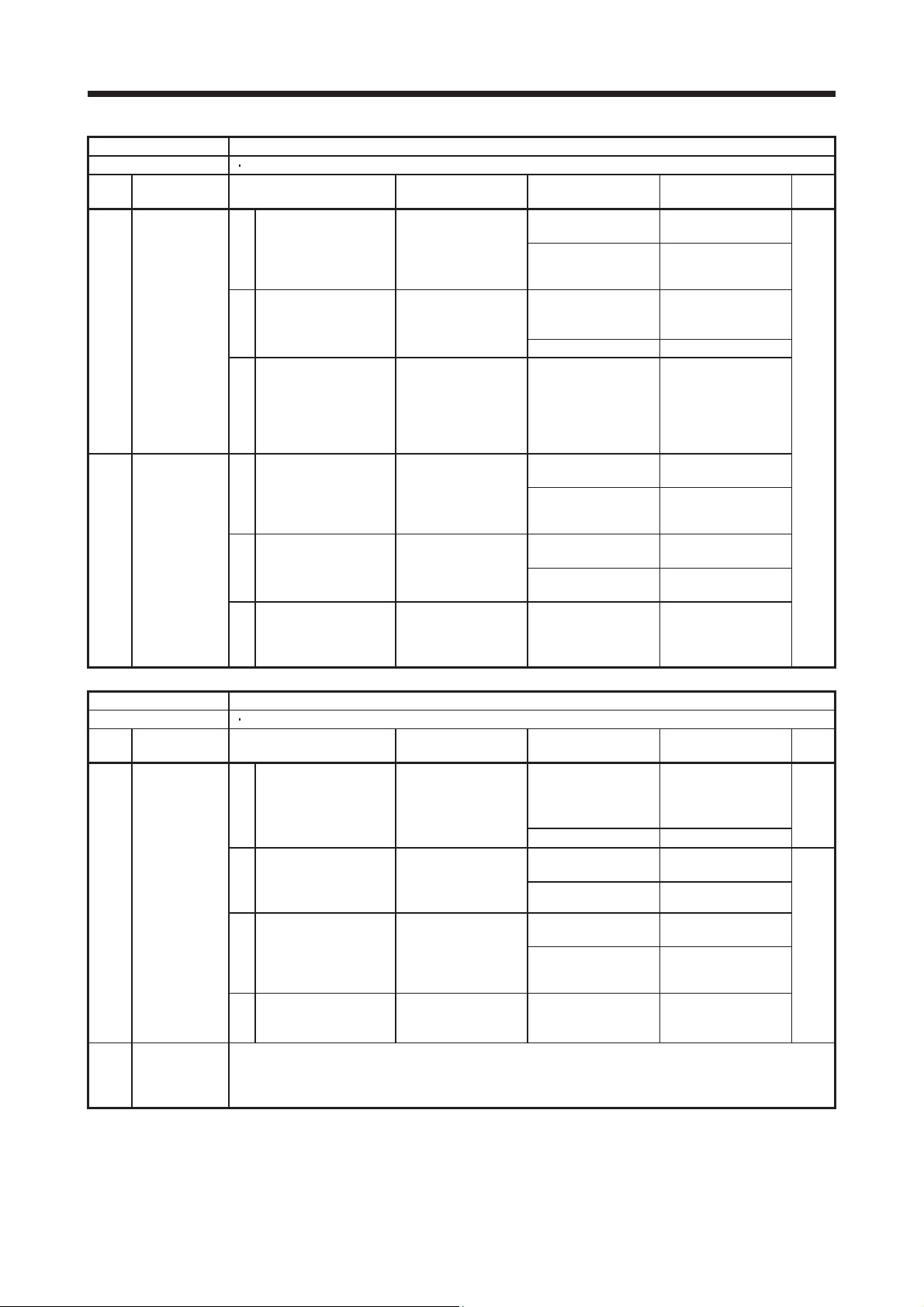
No. Name
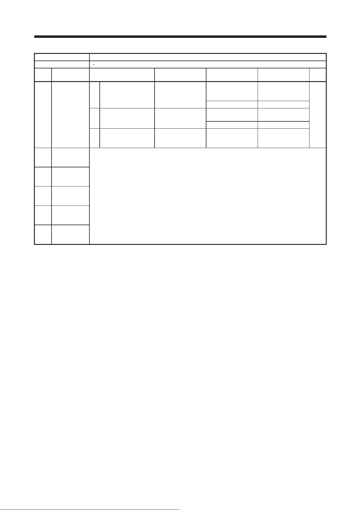
Warning
91 Servo amplifier overheat warning 91.1 Main circuit device overheat warning
92 92.1 Encoder battery cable disconnection warning
Battery cable disconnection
warning
95 STO warning 95.1 STO1 off detection
95.2 STO2 off detection
96 Home position setting warning 96.1 In-position warning at home positioning
96.2 Command input warning at home positioning
96.3 Servo off warning at home positioning
99 Stroke limit warning 99.1 Forward rotation stroke end off
99.2 Reverse rotation stroke end off
9F Battery warning 9F.1 Low battery
9F.2 Battery degradation warning
E0 Excessive regeneration warning E0.1 Excessive regeneration warning
E1 Overload warning 1 E1.1 Thermal overload warning 1 during operation
E1.2 Thermal overload warning 2 during operation
E1.3 Thermal overload warning 3 during operation
E1.4 Thermal overload warning 4 during operation
E1.5 Thermal overload error 1 during a stop
E1.6 Thermal overload error 2 during a stop
E1.7 Thermal overload error 3 during a stop
E1.8 Thermal overload error 4 during a stop
E2 Servo motor overheat warning E2.1 Servo motor temperature warning
E3 Absolute position counter warning E3.1 Multi-revolution counter travel distance excess warning
E3.2 Encoder absolute positioning counter warning
E3.5 Absolute position counter warning
E4 Parameter warning E4.1 Parameter setting range error warning
E5 ABS time-out warning E5.1 Time-out during ABS data transfer
E5.2 ABSM off during ABS data transfer
E5.3 SON off during ABS data transfer
E6 Servo forced stop warning E6.1 Forced stop warning
E7 Controller forced stop warning E7.1 Controller forced stop warning
E8 Cooling fan speed reduction
warning
E9 Main circuit off warning E9.1 Servo-on signal on during main circuit off
E9.2 Bus voltage drop during low speed operation
E9.3 Ready-on signal on during main circuit off
EA ABS servo-on warning EA.1 ABS servo-on warning
EB The other axis error warning EB.1 The other axis error warning
EC Overload warning 2 EC.1 Overload warning 2
ED Output watt excess warning ED.1 Output watt excess warning
F0 Tough drive warning F0.1 Instantaneous power failure tough drive warning
F0.3 Vibration tough drive warning
F2 Drive recorder - Miswriting warning F2.1 Drive recorder - Area writing time-out warning
F2.2 Drive recorder - Data miswriting warning
F3 Oscillation detection warning F3.1 Oscillation detection warning
Detail
display
92.3 Battery degradation
E8.1 Decreased cooling fan speed warning
Detail name
1 - 4
Page 12
1. TROUBLESHOOTING
1.2 Remedies for alarms When any alarm has occurred, eliminate its cause, ensure safety, and deactivate
the alarm before restarting operation. Otherwise, it may cause injury.
CAUTION
If [AL. 25 Absolute position erased] occurs, always make home position setting
again. Otherwise, it may cause an unexpected operation.
As soon as an alarm occurs, make the Servo-off status and interrupt the main
circuit power.
POINT
When any of the following alarms has occurred, do not cycle the power
repeatedly to restart. Doing so will cause a malfunction of the servo amplifier
and the servo motor. Remove its cause and allow about 30 minutes for cooling
before resuming the operation.
[AL. 30 Regenerative error] • [AL. 45 Main circuit device overheat]
[AL. 46 Servo motor overheat] • [AL. 50 Overload 1]
[AL. 51 Overload 2]
Remove the cause of the alarm in accordance with this section. Use MR Configurator2 to refer to a factor of
alarm occurrence.
1 - 5
Page 13

1. TROUBLESHOOTING
Alarm No.: 10 Name: Undervoltage
Alarm content
Displ
10.1 Voltage drop in
10.2 Voltage drop in
Detail name Cause Check method Check result Action
ay
the control
power
(2) The voltage of the
the main circuit
power
It is connected. Check (2).
(2) The voltage of the main
(3) The alarm has
The voltage is 200 V
(4) The servo amplifier is
The voltage of the control circuit power supply has dropped.
The voltage of the main circuit power supply has dropped.
The connection of the
(1) Check the control
control circuit power
supply connector
(CNP2) has a failure.
control circuit power
supply is low.
(3) An instantaneous
power failure has
occurred for longer
time than the specified
time. The time will be
60 ms when [Pr. PA20]
is "_ 0 _ _". The time
will be the value set in
[Pr. PF25] when [Pr.
PA20] is "_ 1 _ _".
(1) The main circuit power
supply connector
(CNP1) was
disconnected.
circuit power supply is
low.
occurred during
acceleration.
malfunctioning.
circuit power supply
connector.
Check if the voltage
of the control circuit
power supply is lower
than 160 V AC.
Check if the power
has a problem.
Check the main
circuit power supply
connector.
Check if the voltage
of the main circuit
power supply is lower
than 160 V AC.
Check that the bus
voltage during
acceleration is 200 V
DC or more.
Check the bus
voltage value.
It has a failure. Connect it correctly.
It has no failure. Check (2).
The voltage is lower
than 160 V AC.
The voltage is higher
than 160 V AC.
It has a problem. Review the power.
It is disconnected. Connect it correctly.
The voltage is lower
than 160 V AC.
The voltage is higher
than 160 V AC.
The voltage is less
than 200 V DC.
DC or more.
The voltage of the
main circuit power
supply is 160 V AC or
more, and the bus
voltage is less than
200 V DC.
Review the voltage of
the control circuit
power supply.
Check (3).
Increase the voltage
of the main circuit
power supply.
Check (3).
Increase the
acceleration time
constant. Or increase
the power supply
capacity.
Check (4).
Replace the servo
amplifier.
Targe
t
[A]
[B]
[WB]
1 - 6
Page 14
1. TROUBLESHOOTING
Alarm No.: 11 Name: Switch setting error
Alarm content
Displ
11.1 Axis number
11.2 Disabling
The setting is other
Detail name Cause Check method Check result Action
ay
setting error
Both of the auxiliary
control axis
setting error
The setting of the axis selection rotary switch or auxiliary axis number setting switch is incorrect.
The setting of the disabling control axis switch is incorrect.
(1) The setting of the Axis
No. is incorrect.
(1) The setting of the
disabling control axis
switch is incorrect.
Check the settings of
the auxiliary axis
number setting switch
(SW2) and axis
selection rotary switch
(SW1).
Check the setting of
the disabling control
axis switch.
When both of the
auxiliary axis number
setting switches are
on, check the axis
selection rotary switch
if "E" is selected for
MR-J4W2, ("E" or "F"
is selected for MRJ4W2).
axis number setting
switches are off.
Check if the setting is
as follows.
1) Only A-axis is
disabled.
2) Only B-axis is
disabled.
3) A-axis and B-axis
are disabled.
4) A-axis and C-axis
are disabled.
than above.
Set the axis No.
correctly.
Replace the servo
amplifier.
Set it correctly.
Replace the servo
amplifier.
Targe
t
[WB]
Alarm No.: 12 Name: Memory error 1 (RAM)
Alarm content A part (RAM) in the servo amplifier is failure.
Displ
12.1 RAM error 1 (1) A part in the servo
12.2 RAM error 2 Check it with the check method for [AL. 12.1].
12.3 RAM error 3
12.4 RAM error 4
12.5 RAM error 5
Detail name Cause Check method Check result Action
ay
Disconnect the cables
amplifier is failure.
(2) Something near the
device caused it.
except the control
circuit power supply,
and then check the
repeatability.
Check the power
supply for noise.
It is repeatable. Replace the servo
amplifier.
It is not repeatable. Check (2).
It has a failure. Take
countermeasures
against its cause.
Targe
t
[A]
[B]
[WB]
1 - 7
Page 15
1. TROUBLESHOOTING
Alarm No.: 13 Name: Clock error
Alarm content
Displ
13.1 Clock error 1 (1) A part in the servo
13.2 Clock error 2 Check it with the check method for [AL. 13.1].
Detail name Cause Check method Check result Action
ay
(2) It occurs. Replace the
(3) The servo amplifier of
It is not
(4) Something near the
A part in the servo amplifier is failure.
A clock error transmitted from the controller occurred.
Disconnect the cables
amplifier is failure.
A clock error
transmitted from the
controller occurred.
the next axis is
malfunctioning.
device caused it.
except the control
circuit power supply,
and then check the
repeatability.
Check if the error
occurs when you
connect the amplifier
to the controller.
Check if the servo
amplifier of the next
axis is malfunctioning.
Check the power
supply for noise.
Check if the
connector is shorted.
It is repeatable. Replace the servo
amplifier.
It is not repeatable. Check (2).
controller.
It does not occur. Check (3).
It is malfunctioning. Replace the servo
amplifier of the next
axis.
Check (4).
malfunctioning.
It has a failure. Take
countermeasures
against its cause.
Targe
t
[A]
[B]
[WB]
[B]
[WB]
[A]
[B]
[WB]
1 - 8
Page 16
1. TROUBLESHOOTING
Alarm No.: 14 Name: Control process error
Alarm content The process did not complete within the specified time.
Displ
14.1 Control
Detail name Cause Check method Check result Action
ay
(1) The parameter setting
process error 1
It is correct. Check (2).
(2) Something near the
is incorrect.
device caused it.
Check if the
parameter setting is
incorrect.
Check the power
supply for noise.
Check if the
connector is shorted.
It is incorrect. Set it correctly.
It has a failure. Take
countermeasures
against its cause.
It has no failure. Check (3).
Targe
t
[A]
[B]
[WB]
(3) The servo amplifier is
malfunctioning.
14.2 Control
process error 2
(2) The parameter setting
It is correct. Check (3).
(3) Something near the
(4) The servo amplifier is
14.3 Control
process error 3
14.4 Control
process error 4
14.5 Control
process error 5
14.6 Control
process error 6
14.7 Control
process error 7
14.8 Control
process error 8
14.9 Control
process error 9
14.A Control process
error 10
A synchronous signal
(1) It is repeatable. Replace the servo
error transmitted from
the controller occurred.
is incorrect.
device caused it.
malfunctioning.
Check it with the check method for [AL. 14.1].
Replace the servo
amplifier, and then
check the
repeatability.
Replace the
controller, and then
check the
repeatability.
Check if the
parameter setting is
incorrect.
Check the power
supply for noise.
Check if the
connector is shorted.
Replace the servo
amplifier, and then
check the
repeatability.
It is not repeatable. Replace the servo
amplifier.
amplifier.
It is not repeatable. Check (2).
It is incorrect. Set it correctly.
It has a failure. Take
countermeasures
against its cause.
It has no failure. Check (4).
It is not repeatable. Replace the servo
amplifier.
[B]
[WB]
[A]
[B]
[WB]
1 - 9
Page 17
1. TROUBLESHOOTING
Alarm No.: 15 Name: Memory error 2 (EEP-ROM)
Alarm content A part (EEP-ROM) in the servo amplifier is failure.
Displ
15.1 EEP-ROM error
15.2 EEP-ROM error
Detail name Cause Check method Check result Action
ay
EEP-ROM is
(1) It is repeatable. Replace the servo
at power on
(2) Something near the
(3) The number of write
during operation
(2) It takes an hour or
(3) Something near the
malfunctioning at power
on.
device caused it.
times exceeded
100,000.
EEP-ROM is
(1) It occurs. Replace the servo
malfunctioning during
normal operation.
A write error occurred
while tuning results was
processed.
device caused it.
Disconnect the cables
except the control
circuit power supply,
and then check the
repeatability.
Check the power
supply for noise.
Check if the connector
is shorted.
Check if parameters
has been used very
frequently.
Check if the error
occurs when you
change parameters
during normal
operation.
Check if the alarm
occurs after an hour
from power on.
Check the power
supply for noise.
Check if the connector
is shorted.
It is not repeatable. Check (2).
It has a failure. Take
It has no failure. Check (3).
It has a failure. Replace the servo
It does not occur. Check (2).
more.
It takes less than an
hour.
It has a failure. Take
amplifier.
countermeasures
against its cause.
amplifier. Change the
process to use
parameters less
frequently after
replacement.
amplifier.
Replace the servo
amplifier.
Check (3).
countermeasures
against its cause.
Targe
t
[A]
[B]
[WB]
Alarm No.: 16 Name: Encoder initial communication error 1
Alarm content Communication error occurred between encoder and servo amplifier.
Displ
16.1 Encoder initial
16.2 Encoder initial
Detail name Cause Check method Check result Action
ay
(1) An encoder cable is
communication
- Receive data
error 1
(2) The servo amplifier is
(3) An encoder is
(4) Something near the
communication
- Receive data
error 2
malfunctioning.
malfunctioning.
malfunctioning.
device caused it.
Check it with the check method for [AL. 16.1].
Check if the encoder
cable is disconnected
or shorted.
Replace the servo
amplifier, and then
check the
repeatability.
Replace the servo
motor or linear
encoder, and then
check the
repeatability.
Check the noise,
ambient temperature,
vibration, etc.
It has a failure. Replace or repair the
It has no failure. Check (2).
It is not repeatable. Replace the servo
It is repeatable. Check (3).
It is not repeatable. Replace the servo
It is repeatable. Check (4).
It has a failure. Take
cable.
amplifier.
motor.
countermeasures
against its cause.
Targe
t
[A]
[B]
[WB]
1 - 10
Page 18
1. TROUBLESHOOTING
Alarm No.: 16 Name: Encoder initial communication error 1
Alarm content Communication error occurred between encoder and servo amplifier.
Displ
16.3 (1) Check the setting of
16.5 Encoder initial
16.6 Encoder initial
16.7 Encoder initial
Detail name Cause Check method Check result Action
ay
Encoder initial
communication Receive data
error 3
(2) An encoder cable was
(3) The setting is
(4) An encoder cable is
(5) The voltage of the
It has no failure. Check (6).
(6) The servo amplifier is
(7) An encoder is
(8) Something near the
communication Transmission
data error 1
communication Transmission
data error 2
communication Transmission
data error 3
An axis not used is not
set as disabled-axis.
disconnected.
The parameter setting
of two-wire type/fourwire type is incorrect.
Type A: [Pr. PC22]
Type B: [Pr. PC04]
malfunctioning.
control circuit power
supply has been
unstable.
malfunctioning.
malfunctioning.
device caused it.
Check it with the check method for [AL. 16.1].
the disabling control
axis switch (SW2).
It is set as disabled-
Check if the encoder
cable is connected
correctly.
Check the parameter
setting.
Check if the encoder
cable is disconnected
or shorted.
Check the voltage of
the control circuit
power supply.
Replace the servo
amplifier, and then
check the
repeatability.
Replace the servo
motor, and then
check the
repeatability.
Check the noise,
ambient temperature,
vibration, etc.
It is not set as
disabled-axis.
axis.
It is not connected. Connect it correctly.
It is connected. Check (3).
incorrect.
The setting is correct. Check (4).
It has a failure. Replace or repair the
It has no failure. Check (5).
The control circuit
power supply has
been an
instantaneous power
failure.
It is not repeatable. Replace the servo
It is repeatable. Check (7).
It is not repeatable. Replace the servo
It is repeatable. Check (8).
It has a failure. Take
Set it as disabled-
axis.
Check (2).
Set it correctly.
cable.
Review the power
and related parts.
amplifier.
motor.
countermeasures
against its cause.
Targe
t
[WB]
[A]
[B]
[WB]
1 - 11
Page 19
1. TROUBLESHOOTING
Alarm No.: 16 Name: Encoder initial communication error 1
Alarm content Communication error occurred between encoder and servo amplifier.
Displ
16.A Encoder initial
16.B Encoder initial
16.C Encoder initial
16.D Encoder initial
16.E Encoder initial
16.F Encoder initial
Detail name Cause Check method Check result Action
ay
(1) The servo amplifier is
communication Process error 1
(2) An encoder is
(3) Something near the
communication Process error 2
communication Process error 3
communication Process error 4
communication Process error 5
communication Process error 6
malfunctioning.
malfunctioning.
device caused it.
Check it with the check method for [AL. 16.A].
Replace the servo
amplifier, and then
check the
repeatability.
Replace the servo
motor, and then check
the repeatability.
Check the noise,
ambient temperature,
vibration, etc.
It is not repeatable. Replace the servo
It is repeatable. Check (2).
It is not repeatable. Replace the servo
It is repeatable. Check (3).
It has a failure. Take
amplifier.
motor.
countermeasures
against its cause.
Targe
t
[A]
[B]
[WB]
1 - 12
Page 20

1. TROUBLESHOOTING
Alarm No.: 17 Name: Board error
Alarm content A part in the servo amplifier is malfunctioning.
Displ
17.1 Board error 1 (1) A current detection
17.3 Board error 2 Check it with the check method for [AL. 17.1]".
17.4 Board error 3 (1) It is repeatable. Replace the servo
17.5 Board error 4 (1) It is repeatable. Replace the servo
17.6 Board error 5 (1) It is repeatable. Replace the servo
Detail name Cause Check method Check result Action
ay
circuit is
malfunctioning.
(2) Something near the
device caused it.
The servo amplifier
recognition signal was
not read properly.
(2) Something near the
device caused it.
The setting value of the
rotary switch (SW1)
was not read properly.
(2) Something near the
device caused it.
The setting value of the
DIP switches (SW2)
was not read properly.
(2) Something near the
device caused it.
Check if the alarm
occurs during the
servo-on status.
Check the noise,
ambient temperature,
etc.
Disconnect the cables
except the control
circuit power supply,
and then check the
repeatability.
Check the noise,
ambient temperature,
etc.
Disconnect the cables
except the control
circuit power supply,
and then check the
repeatability.
Check the noise,
ambient temperature,
etc.
Disconnect the cables
except the control
circuit power supply,
and then check the
repeatability.
Check the noise,
ambient temperature,
etc.
It occurs. Replace the servo
It does not occur. Check (2).
It has a failure. Take
It is not repeatable. Check (2).
It has a failure. Take
It is not repeatable. Check (2).
It has a failure. Take
It is not repeatable. Check (2).
It has a failure. Take
amplifier.
countermeasures
against its cause.
amplifier.
countermeasures
against its cause.
amplifier.
countermeasures
against its cause.
amplifier.
countermeasures
against its cause.
Targe
t
[A]
[B]
[WB]
[B]
[WB]
1 - 13
Page 21

1. TROUBLESHOOTING
Alarm No.: 19 Name: Memory error 3 (Flash-ROM)
Alarm content A part (Flash-ROM) in the servo amplifier is failure.
Displ
19.1 Flash-ROM
19.2 Flash-ROM
Alarm No.: 1A Name: Servo motor combination error
Displ
1A.1 Servo motor
1A.2 Servo motor
Detail name Cause Check method Check result Action
ay
(1) The Flash-ROM is
error 1
(2) Something near the
error 2
Alarm content The combination of servo amplifier and servo motor is incorrect.
Detail name Cause Check method Check result Action
ay
combination
error
(2) The setting of [Pr.
(3) An encoder is
control mode
combination
error
malfunctioning.
device caused it.
Check it with the check method for [AL. 19.1].
The servo amplifier and
(1) The combination is
the servo motor was
connected incorrectly.
PA01] is not
correspondingto the
connected servo motor.
malfunctioning.
(1) The setting of [Pr.
PA01] is not
correspondingto the
connected servo motor.
Disconnect the cables
except the control
circuit power supply,
and then check the
repeatability.
Check the noise,
ambient temperature,
etc.
Check the model
name ofthe servo
motor and
correspondingservo
amplifier.
Check the [Pr. PA01]
setting.
Rotary servo motor:
"_ _ 0 _"
Linear servo motor: "_
_ 4 _"
Direct drive motor: "_
_ 6 _"
Replace the servo
motor, and then
check the
repeatability.
Check the [Pr. PA01]
setting.
Rotary servo motor:
"_ _ 0 _"
Linear servo motor: "_
_ 4 _"
Direct drive motor: "_
_ 6 _"
It is repeatable. Replace the servo
amplifier.
It is not repeatable. Check (2).
It has a failure. Take
countermeasures
against its cause.
Use them in the
incorrect.
The combination is
correct.
The combination is
incorrect.
The combination is
correct.
It is not repeatable. Replace the servo
The combination is
incorrect.
correct combination.
Check (2).
Set [Pr. PA01]
correctly.
Check (3).
motor.
Set [Pr. PA01]
correctly.
Targe
t
[A]
[B]
[WB]
Targe
t
[A]
[B]
[WB]
[B]
[WB]
[A]
[B]
[WB]
[B]
[WB]
Alarm No.: 1E Name: Encoder initial communication error 2
Alarm content An encoder is malfunctioning.
Displ
1E.1 Encoder
Detail name Cause Check method Check result Action
ay
(1) An encoder is
malfunction
(2) Something near the
malfunctioning.
device caused it.
Replace the servo
motor, and then
check the
repeatability.
Check the noise,
ambient temperature,
vibration, etc.
1 - 14
It is not repeatable. Replace the servo
motor.
It is repeatable. Check (2).
It has a failure. Take
countermeasures
against its cause.
Targe
t
[A]
[B]
[WB]
Page 22

1. TROUBLESHOOTING
Alarm No.: 1F Name: Encoder initial communication error 3
Alarm content The connected encoder is not compatible with the servo amplifier.
Displ
1F.1 Incompatible
Detail name Cause Check method Check result Action
ay
(1) A servo motor or linear
encoder
It is compatible with
(2) The software version of
It is supported. Check (3).
(3) An encoder is
encoder, which is not
compatible with the
servo amplifier, was
connected.
the servo amplifier
does not support the
servo motor or linear
encoder.
malfunctioning.
Check the model the
servo motor/linear
encoder.
Check if the software
version supportsthe
servo motor/linear
encoder.
Replace the servo
motor or linear
encoder, and then
check the
repeatability.
It is not compatible
with the servo
amplifier.
the servo amplifier.
It is not supported. Replace the servo
It is not repeatable. Replace the servo
It is repeatable. Replace the servo
Replace it with a
compatible one.
Check (2).
amplifier to one which
software version
supports the servo
motor/linear encoder.
motor or linear
encoder.
amplifier.
Targe
t
[A]
[B]
[WB]
1 - 15
Page 23

1. TROUBLESHOOTING
Alarm No.: 20 Name: Encoder normal communication error 1
Alarm content Communication error occurred between encoder and servo amplifier.
Displ
20.1 (1) An encoder cable is
20.2 Encoder normal
20.3 Encoder normal
20.5 Encoder normal
20.6 Encoder normal
20.7 Encoder normal
20.9 Encoder normal
20.A Encoder normal
Detail name Cause Check method Check result Action
ay
Encoder normal
communication
- Receive data
error 1
(2) The servo amplifier is
(3) An encoder is
(4) Something near the
communication
- Receive data
error 2
communication
- Receive data
error 3
communication
- Transmission
data error 1
communication
- Transmission
data error 2
communication
- Transmission
data error 3
communication
- Receive data
error 4
communication
- Receive data
error 5
malfunctioning.
malfunctioning.
malfunctioning.
device caused it.
Check it with the check method for [AL. 20.1].
Check if the encoder
cable is disconnected
or shorted.
Replace the servo
amplifier, and then
check the
repeatability.
Replace the servo
motor or linear
encoder, and then
check the
repeatability.
Check the noise,
ambient temperature,
vibration, etc.
It has a failure. Repair or replace the
It has no failure. Check (2).
It is not repeatable. Replace the servo
It is repeatable. Check (3).
It is not repeatable. Replace the servo
It is repeatable. Check (4).
It has a failure. Take
cable.
amplifier.
motor or linear
encoder.
countermeasures
against its cause.
Targe
t
[A]
[B]
[WB]
1 - 16
Page 24

1. TROUBLESHOOTING
Alarm No.: 21 Name: Encoder normal communication error 2
Alarm content The encoder detected an error signal.
Displ
21.1 Encoder data
21.2 Encoder data
21.3 Encoder data
21.4 Encoder non-
21.5 Encoder
21.6 Encoder
21.9 Encoder data
Detail name Cause Check method Check result Action
ay
(1) The encoder detected
error 1
It is repeatable. Check (2).
(2) An encoder is
(3) Something near the
update error
(2) Something near the
waveform error
signal error
(2) Something near the
hardware error
1
hardware error
2
error 2
a high
speed/acceleration rate
due to an oscillation or
other factors.
malfunctioning.
device caused it.
(1) An encoder is
malfunctioning.
device caused it.
Check it with the check method for for [AL. 21.2].
A signal of the linear
(1) It has a failure. Review the wiring. [B]
encoder has not been
inputted.
device caused it.
Check it with the check method for [AL. 21.2].
Check it with the check method for [AL. 21.1].
Decrease the loop
gain, and then check
the repeatability.
Replace the servo
motor, and then
check the
repeatability.
Check the noise,
ambient temperature,
vibration, etc.
Replace the servo
motor, and then
check the
repeatability.
Check the noise,
ambient temperature,
etc.
Check if the linear
encoder cable is
wired correctly.
Check the noise,
ambient temperature,
etc.
It is not repeatable. Use the encoder with
low loop gain.
It is not repeatable. Replace the servo
motor.
It is repeatable. Check (3).
It has a failure. Take
countermeasures
against its cause.
It is not repeatable. Replace the servo
motor.
It is repeatable. Check (2).
It has a failure. Take
countermeasures
against its cause.
It has no failure. Check (2).
It has a failure. Take
countermeasures
against its cause.
Targe
t
[A]
[B]
[WB]
[WB]
1 - 17
Page 25

1. TROUBLESHOOTING
Alarm No.: 24 Name: Main circuit error
Alarm content
Displ
24.1 (1) The servo amplifier is
24.2 Ground fault
Detail name Cause Check method Check result Action
ay
Ground fault
detected by
hardware
detection circuit
(2) A ground fault or short
(3) A ground fault occurred
(4) They are in contact. Correct the wiring.
(5) Something near the
detected by
software
detection
function
A ground fault occurred on the servo motor power lines.
A ground fault occurred at the servo motor.
Disconnect the servo
malfunctioning.
occurred at the servo
motor power cable.
at the servo motor.
The main circuit power
supply cable and servo
motor power cable
were shorted.
device caused it.
Check it with the check method for [AL. 24.1].
motor power cables
(U, V, and W) and
check if the alarm
occurs.
Check if only the
servo motor power
cable is shorted.
Disconnect the servo
motor power cables
on motor side, and
check insulation of
the motor (between
U, V, W, and
Shut off the power,
and check if the main
circuit power supply
cable and servo
motor power cable
are in contact.
Check the noise,
ambient temperature,
etc.
).
It occurs. Replace the servo
amplifier.
It does not occur. Check (2).
It is shorted. Replace the servo
motor power cable.
It is not shorted. Check (3).
It is shorted. Replace the servo
motor.
It is not shorted. Check (4).
They are not in
contact.
It has a failure. Take
Check (5).
countermeasures
against its cause.
Targe
t
[A]
[B]
[WB]
1 - 18
Page 26

1. TROUBLESHOOTING
Alarm No.: 25 Name: Absolute position erased
Alarm content
Displ
25.1 Servo motor
Detail name Cause Check method Check result Action
ay
encoder Absolute
position erased
This is not the first
(2) The battery was
It was not removed. Check (3).
(3) It is less than DC 3.0 V.Replace the battery.
(4) The voltage drop of the
It is used. Check (5).
(5) A battery cable is
It has no failure. Check (6).
(6) There is a loose
(7) It is not connected. Connect the absolute
(8) The servo amplifier is
(9) An encoder is
Absolute position data in error
Power was switched on for the first time in the absolute position detection system.
(1) Power was switched on
for the first time in the
absolute position
detection system.
removed (replaced)
when the control circuit
power supply was off.
The battery voltage is
low. The battery is
consumed.
battery cable is large.
malfunctioning.
connection of the
encoder cable on the
servo motor side.
The absolute position
storage unit was not
connected for using a
direct drive motor.
malfunctioning.
malfunctioning.
Check if this is the
first time in the
absolute position
detection system.
Check if the battery
was removed
(changed) when the
control circuit power
supply was off.
Check the battery
voltage with a tester.
Check if a
recommended wire is
used.
Check for the loose
connection with a
tester.
Check for the loose
connection with a
tester. Measure the
voltage on the servo
motor side.
Check if the absolute
position storage unit
is connected
correctly.
Replace the servo
amplifier, and then
check the
repeatability.
Replace the servo
motor, and then
check the
repeatability.
This is the first time. Check that the battery
time.
It was removed. Check that the battery
It is DC 3.0 V or
more.
It is not used. Use a recommended
It has a failure. Replace the battery
It has a failure. Repair or replace the
It has no failure. Check (7).
It is connected. Check (8).
It is not repeatable. Replace the servo
It is repeatable. Check (9).
It is not repeatable. Replace the servo
is mounted, and
make home position
return.
Check (2).
is mounted, and
make home position
return.
Check (4).
wire.
cable.
encoder cable.
position storage unit
correctly.
amplifier.
motor.
Targe
t
[A]
[B]
[WB]
[B]
[WB]
[A]
[B]
[WB]
1 - 19
Page 27

1. TROUBLESHOOTING
Alarm No.: 27 Name: Initial magnetic pole detection error
Alarm content The initial magnetic pole detection was not completed properly.
Displ
27.1 (1) A moving part collided
27.2 Magnetic pole
27.3
27.4
27.5
27.6
27.7
Detail name Cause Check method Check result Action
ay
Magnetic pole
detection Abnormal
termination
(2) The wiring of the servo
(3) The setting is
(5) The magnetic pole
Check if the travel
detection Time out error
It has no failure. Check (2).
(2) The magnetic pole
Magnetic pole
detection Limit switch
error
Magnetic pole
detection Estimated error
Magnetic pole
detection Position
deviation error
Magnetic pole
detection Speed
deviation error
Magnetic pole
detection Current error
against the machine.
It did not collided. Check (2).
motor power cable is
incorrect.
The linear encoder
resolution setting
differs from the setting
value.
The direction of
(4) The mounting
mounting linear
encoder is incorrect.
detection voltage level
is small.
(1) Only one of the limit
switches of FLS/RLS is
on.
detection voltage level
is small.
(1) Both of the limit
switches of FLS/RLS
are on during the
magnetic pole
detection.
Check it with the check method for [AL. 27.1].
Check if it collided. It collided. Move the start
position of the
magnetic pole
detection.
Check if the wiring of
the servo motor
power cable is
correct.
Check the setting of
[Pr. PL02] and [Pr.
PL03].
Check polarities of
the linear encoder
and the linear servo
motor.
Check if the travel
distance during the
magnetic pole
detection is too short
(for a position
detection method).
distance during the
magnetic pole
detection is too long
or if a vibration is
occurring (for a
minute position
detection method).
Check the limit
switches.
Check if the travel
distance during the
magnetic pole
detection is too short
(for a position
detection method).
Check the limit
switches.
It has a failure. Correct the wiring.
It has no failure. Check (3).
Set it correctly.
incorrect.
The setting is correct. Check (4).
Mount it correctly.
direction is incorrect.
The mounting
direction is correct.
It is too short. Increase it with the
The travel distance is
too long or a vibration
is occurring.
It has a failure. Remove the cause.
It is too short. Increase it with the
Both of them are off. Turn on the limit
Check (5).
[Pr. PL09] setting.
Review the [Pr. PL17]
setting.
Move the start
position of the
magnetic pole
detection.
[Pr. PL09] setting.
switches.
Targe
t
[B]
[WB]
1 - 20
Page 28

1. TROUBLESHOOTING
Alarm No.: 28 Name: Linear encoder error 2
Alarm content Working environment of linear encoder is not normal.
Displ
28.1 Linear encoder
Alarm No.: 2A Name: Linear encoder error 1
Displ
2A.1 Linear encoder
2A.2 Linear encoder
2A.3 Linear encoder
2A.4 Linear encoder
2A.5 Linear encoder
2A.6 Linear encoder
2A.7 Linear encoder
2A.8 Linear encoder
Detail name Cause Check method Check result Action
ay
(1) The ambient
- Environment
error
It is within
(2) The signal level of the
Alarm content
Detail name Cause Check method Check result Action
ay
error 1-1
(2) Something near the
(3) An alarm of the linear
error 1-2
error 1-3
error 1-4
error 1-5
error 1-6
error 1-7
error 1-8
temperature of the
linear encoder is out of
specifications.
linear encoder has
dropped.
An error of the linear encoder was detected. (The details differ depending on the linear encoder
manufacturer.)
Mounting condition of
(1) It is not repeatable. Use the equipment at
the linear encoder and
head is failure.
device caused it.
encoder was detected.
Check it with the check method for [AL. 2A.1].
Check the ambient
temperature of the
linear encoder.
Check the mounting
condition of the linear
encoder.
Adjust the positions of
the scale and head,
and then check the
repeatability.
Check the noise,
ambient temperature,
vibration, etc.
Check the content of
the alarm detail list of
the Linear Encoder
Instruction Manual.
It is out of
specifications.
specifications.
It has a failure. Correct the mounting
It is repeatable. Check (2).
It has a failure. Take
It has no failure. Check (3).
Remove its cause
described in the
instruction manual.
Lower the
temperature. Contact
the linear encoder
manufacturer.
Check (2).
method of the linear
encoder.
the adjusted position.
countermeasures
against its cause.
Contact each encoder
manufacturer for how
to deal with it.
Targe
t
[B]
[WB]
Targe
t
[B]
[WB]
1 - 21
Page 29

1. TROUBLESHOOTING
Alarm No.: 2B Name: Encoder counter error
Alarm content Data which encoder created is failure.
Displ
2B.1 Encoder
2B.2 Encoder
Alarm No.: 30 Name: Regenerative error
Displ
30.1 Regeneration
30.2 Regeneration
30.3 (1) A detection circuit of
Detail name Cause Check method Check result Action
ay
(1) An encoder cable is
counter error 1
(2) Something near the
(3) An encoder is
counter error 2
Alarm content
Detail name Cause Check method Check result Action
ay
heat error
(2) It is not connected
(3) Power supply voltage
It is less than 240 V
(4) The regenerative load
signal error
Regeneration
feedback signal
error
(2) Something near the
malfunctioning.
device caused it.
malfunctioning.
Check it with the check method for [AL. 2B.1].
Permissible regenerative power of the built-in regenerative resistor or regenerative option is exceeded.
A regenerative transistor in the servo amplifier is malfunctioning.
The setting of the
(1) The setting value is
regenerative resistor
(regenerative option) is
incorrect.
The regenerative
resistor (regenerative
option) is not
connected.
high.
ratio has been over
100%.
(1) A detection circuit of
the servo amplifier is
malfunctioning.
the servo amplifier is
malfunctioning.
device caused it.
Check if the encoder
cable is disconnected
or shorted.
Check the noise,
ambient temperature,
vibration, etc.
Replace the direct
drive motor, and then
check the
repeatability.
Check the
regenerative resistor
(regenerative option)
and [Pr. PA02]
setting.
Check if the
regenerative resistor
(regenerative option)
is connected
correctly.
Check the input
power supply voltage.
Check the
regenerative load
ratio when alarm
occurs.
Check if the
regenerative resistor
(regenerative option)
is overheating.
Remove the
regenerative option or
built-in regenerative
resistor and then
check if the alarm
occur at power on.
Check the noise,
ground fault, ambient
temperature, etc.
It has a failure. Repair or replace the
It has no failure. Check (2).
It has a failure. Take
It has no failure. Check (3).
It is not repeatable. Replace the direct
incorrect.
It is set correctly. Check (2).
correctly.
It is connected
correctly.
It is 240 V AC or
more.
AC.
It is 100% or more. Reduce the frequency
It is overheating
abnormally.
The alarm occurs. Replace the servo
The alarm does not
occur.
It has a failure. Take
cable.
countermeasures
against its cause.
drive motor.
Set it correctly.
Connect it correctly.
Check (3).
Reduce the power
supply voltage.
Check (4).
of positioning.
Reduce the load. Use
a regenerative option
if not being using.
Review the
regenerative option
capacity.
Replace the servo
amplifier.
amplifier.
Check (2).
countermeasures
against its cause.
Targe
t
[B]
[WB]
Targe
t
[A]
[B]
[WB]
1 - 22
Page 30

1. TROUBLESHOOTING
Alarm No.: 31 Name: Overspeed
Alarm content
Displ
31.1 (1) The command pulse
Detail name Cause Check method Check result Action
ay
Abnormal
motor speed
(2) The command from the
(3) A larger speed
(4) The servo motor was at
(5) The servo system is
It is not oscillating. Check (6).
(6) The velocity waveform
(8) The encoder or liner
The servo motor seed has exceeded the permissible instantaneous speed.
The linear servo motor seed has exceeded the permissible instantaneous speed.
Check the command
frequency is high.
The command pulse
controller is excessive.
command than the
overspeed alarm level
was inputted.
the maximum torque
(maximum thrust) at
the time of
acceleration.
unstable and
oscillating.
has overshot.
(7) The connection
destination of the
encoder cable is
incorrect.
encoder is
malfunctioning.
pulse frequency.
Check if the
command from the
controller is over the
permissible speed.
Check that the actual
motor speed is higher
than the setting value
of [Pr. PC08
Overspeed alarm
detection level].
Check if the torque
(thrust) at the time of
acceleration is the
maximum torque
(maximum thrust).
Check if the servo
motor is oscillating.
Check if it is
overshooting because
the acceleration time
constant is too short.
Check the connection
destinations of CN2A,
CN2B, and CN2C.
Check if the alarm is
occurring during less
than permissible
instantaneous speed.
The command pulse
frequency is high.
frequency is low.
It is over the
permissible speed.
It is less than the
permissible speed.
The motor speed is
higher than the
overspeed alarm
detection level.
The motor speed is
lower than the
overspeed alarm
level.
It is the maximum
torque (maximum
thrust).
It is less than the
maximum torque
(maximum thrust).
It is oscillating. Adjust the servo gain.
It is overshooting. Increase the
It is not overshooting. Check (7).
It is not correct. Wire it correctly. [WB]
It is correct. Check (8).
It is occurring during
less than permissible
instantaneous speed.
Check operation
pattern.
Check (3).
Check operation
pattern.
Check (3).
Review the [Pr. PC08]
setting.
Check (4).
Increase the
acceleration/decelerat
ion time constant. Or
reduce the load.
Check (5).
Or reduce the load.
acceleration/decelerat
ion time constant.
Replace the servo
motor or linear
encoder.
Targe
t
[A]
[B]
[WB]
[A]
[B]
[WB]
[A]
[B]
[WB]
1 - 23
Page 31

1. TROUBLESHOOTING
Alarm No.: 32 Name: Overcurrent
Alarm content Current that flew is higher than the permissible current of the servo amplifier.
Displ
32.1 (1) The servo amplifier is
Detail name Cause Check method Check result Action
ay
Overcurrent
detected at
hardware
detection circuit
(during
operation)
(2) A ground fault or short
It is not shorted. Check (3).
(3) The servo motor is
(4) The dynamic brake is
(5) It is not correct. Wire it correctly. [WB]
(6) Something near the
malfunctioning.
occurred at the servo
motor power cable.
malfunctioning.
malfunctioning.
The connection
destination of the
encoder cable is
incorrect.
device caused it.
Disconnect the servo
motor power cables
(U, V, and W) and
check if the alarm
occurs.
Check if only the
servo motor power
cable is shorted.
Disconnect the servo
motor power cables
on motor side, and
check insulation of
the motor (between
U, V, W, and
Check if the error
occurs when you turn
on the servo-on
command.
Check the connection
destinations of CN2A,
CN2B, and CN2C.
Check the noise,
ambient temperature,
etc.
It occurs. Replace the servo
amplifier.
It does not occur. Check (2).
It is shorted. Replace the servo
motor power cable.
A ground fault is
occurring.
A ground fault is not
occurring.
).
It occurs. Replace the servo
It does not occur. Check (5).
It is correct. Check (6).
It has a failure. Take
Replace the servo
motor.
Check (4).
amplifier.
countermeasures
against its cause.
Targe
t
[A]
[B]
[WB]
[A]
[B]
[WB]
1 - 24
Page 32

1. TROUBLESHOOTING
Alarm No.: 32 Name: Overcurrent
Alarm content Current that flew is higher than the permissible current of the servo amplifier.
Displ
32.2 (1) The servo gain is high. Check if an oscillation
32.3 Overcurrent
32.4 Overcurrent
Detail name Cause Check method Check result Action
ay
Overcurrent
detected at
software
detection
function (during
operation)
(2) The servo amplifier is
(3) A ground fault or short
It is not shorted. Check (4).
(4) The servo motor is
(5) It is not correct. Connect it correctly. [WB]
(6) Something near the
detected at
hardware
detection circuit
(during a stop)
detected at
software
detection
function (during
a stop)
An oscillation is not
malfunctioning.
occurred at the servo
motor power cable.
malfunctioning.
The connection
destination of the
encoder cable is
incorrect.
device caused it.
Check it with the check method for [AL. 32.1].
Check it with the check method for [AL. 32.2].
is occurring.
Disconnect the servo
motor power cables
(U, V, and W) and
check if the alarm
occurs.
Check if only the
servo motor power
cable is shorted.
Disconnect the servo
motor power cables
on motor side, and
check insulation of
the motor (between
U, V, W, and
Check the connection
destinations of CN2A,
CN2B, and CN2C.
Check the noise,
ambient temperature,
etc.
An oscillation is
occurring.
occurring.
It occurs. Replace the servo
It does not occur. Check (3).
It is shorted. Replace the servo
A ground fault is
occurring.
A ground fault is not
occurring.
).
It is correct. Check (6).
It has a failure. Take
Reduce the speed
loop gain ([Pr. PB09]).
Check (2).
amplifier.
motor power cable.
Replace the servo
motor.
Check (5).
countermeasures
against its cause.
Targe
t
[A]
[B]
[WB]
[A]
[B]
[WB]
1 - 25
Page 33

1. TROUBLESHOOTING
Alarm No.: 33 Name: Overvoltage
Alarm content The value of the bus voltage exceeded 400 V DC.
Displ
33.1 Main circuit
Detail name Cause Check method Check result Action
ay
The setting of the
(1) The setting value is
voltage error
(2) It is not connected
(3) Wire breakage of built-
The resistance is
It is repeatable. Check (5).
(5) Power supply voltage
It is 264 V AC or less. Check (6).
(6) Something near the
regenerative resistor
(regenerative option) is
incorrect.
The regenerative
resistor (regenerative
option) is not
connected.
in regenerative resistor
or regenerative option
(4) The regeneration
capacity is insufficient.
high.
device caused it.
Check the
regenerative resistor
(regenerative option)
and [Pr. PA02]
setting.
Check if the
regenerative resistor
(regenerative option)
is connected
correctly.
Measure the
resistance of the builtin regenerative
resistor or
regenerative option.
Set a larger
deceleration time
constant, and then
check the
repeatability.
Check the input
voltage.
Check the noise,
ambient temperature,
etc.
incorrect.
It is set correctly. Check (2).
correctly.
It is connected
correctly.
The resistance is
abnormal.
normal.
It is not repeatable. When using a built-in
It is over 264 V AC. Reduce the input
It has a failure. Take
Set it correctly.
Connect it correctly.
Check (3).
When using a built-in
regenerative resistor,
replace the servo
amplifier. When using
a regenerative option,
replace the
regenerative option.
Check (4).
regenerative resistor,
use a regenerative
option. When using a
regenerative option,
use a larger capacity
one.
voltage.
countermeasures
against its cause.
Targe
t
[A]
[B]
[WB]
1 - 26
Page 34

1. TROUBLESHOOTING
Alarm No.: 34 Name: SSCNET receive error 1
Alarm content An error occurred in SSCNET III/H communication. (continuous communication error with 3.5 ms interval)
Displ
34.1 SSCNET
34.2 SSCNET
34.3 SSCNET
34.4 Hardware error
Detail name Cause Check method Check result Action
ay
(1) The SSCNET III cable
receive data
error
It is connected. Check (2).
(2) The surface at the end
It is repeatable. Check (3).
(3) The SSCNET III cable
It has no failure. Check (4).
(4) It is used. They are in
(5) The servo amplifier is
(6) It is not repeatable. Replace the servo
(7) The controller is
(8) Something near the
connector
connection
error
communication
data error
signal detection
is disconnected.
of SSCNET III cable
got dirty.
is broken or severed.
A vinyl tape is stacked
tothe SSCNET III
cable. Or a wire
insulator containing
migrating plasticizer is
adhered to the cable.
malfunctioning.
The previous or next
axis servo amplifier of
the alarm occurred is
malfunctioning.
malfunctioning.
device caused it.
Check it with the check method for [AL. 34.1].
Check the SSCNET
III cable connection.
Wipe off the dirt from
the cable tip, and
then check the
repeatability.
Check if the SSCNET
III cable is
malfunctioning.
Check if a vinyl tape
is used. Check if the
cable is contacting
with other cables.
Replace the servo
amplifier, and then
check the
repeatability.
Replace the previous
and next servo
amplifier of the alarm
occurred axis, and
then check the
repeatability.
Replace the
controller, and then
check the
repeatability.
Check the noise,
ambient temperature,
etc.
It is disconnected. Turn off the control
circuit power supply
of the servo amplifier,
and then connect the
SSCNET III cable.
It is not repeatable. Take measure to
keepthe cable tip
clean.
It has a failure. Replace the SSCNET
III cable.
Take
contact.
It is not used. They
are not in contact.
It is not repeatable. Replace the servo
It is repeatable. Check (6).
It is repeatable. Check (7).
It is not repeatable. Replace the
It is repeatable. Check (8).
It has a failure. Take
countermeasures
against its cause.
Check (5).
amplifier.
amplifier.
controller.
countermeasures
against its cause.
Targe
t
[B]
[WB]
1 - 27
Page 35

1. TROUBLESHOOTING
Alarm No.: 35 Name: Command frequency error
Alarm content Input pulse frequency of command pulse is too high.
Displ
35.1 Command
Detail name Cause Check method Check result Action
ay
(1) The command pulse
frequency error
The command pulse
(2) The command from the
(3) The controller is
(4) Something near the
frequency is high.
controller is excessive.
malfunctioning.
device caused it.
Check the command
pulse frequency.
Check if the
command from the
controller is over the
permissible speed.
Replace the
controller, and then
check the
repeatability.
Check the noise,
ambient temperature,
etc.
The command pulse
frequency is high.
frequency is low.
It is over the
permissible speed.
It is less than the
permissible speed.
It is not repeatable. Replace the
It is repeatable. Check (4).
It has a failure. Take
Check operation
pattern.
Check (4).
Check operation
pattern.
Check (3).
controller.
countermeasures
against its cause.
Targe
t
[A]
[B]
[WB]
[A]
[B]
[WB]
1 - 28
Page 36

1. TROUBLESHOOTING
Alarm No.: 36 Name: SSCNET receive error 2
Alarm content
Displ
36.1 Continuous
Detail name Cause Check method Check result Action
ay
communication
data error
It is connected. Check (2).
(2) The surface at the end
It is repeatable. Check (3).
(3) It has a failure. Replace the SSCNET
(4) It is used. They are in
(5) The servo amplifier is
(6) It is not repeatable. Replace the servo
(7) The controller is
(8) Something near the
An error occurred in SSCNET III/H communication. (intermittent communication error with about 70 ms
interval)
(1) The SSCNET III cable
is disconnected.
of SSCNET III cable
got dirty.
The SSCNET III cable
is broken or severed.
A vinyl tape is stacked
tothe SSCNET III
cable. Or a wire
insulator containing
migrating plasticizer is
adhered to the cable.
malfunctioning.
The previous or next
axis servo amplifier of
the alarm occurred is
malfunctioning.
malfunctioning.
device caused it.
Check the SSCNET
III cable connection.
Wipe off the dirt from
the cable tip, and
then check the
repeatability.
Check if the SSCNET
III cable is
malfunctioning.
Check if a vinyl tape
is used. Check if the
cable is contacting
with other cables.
Replace the servo
amplifier, and then
check the
repeatability.
Replace the previous
and next servo
amplifier of the alarm
occurred axis, and
then check the
repeatability.
Replace the
controller, and then
check the
repeatability.
Check the noise,
ambient temperature,
etc.
It is disconnected. Turn off the control
circuit power supply
of the servo amplifier,
and then connect the
SSCNET III cable.
It is not repeatable. Take measure to
keepthe cable tip
clean.
III cable.
It has no failure. Check (4).
Take
contact.
It is not used. They
are not in contact.
It is not repeatable. Replace the servo
It is repeatable. Check (6).
It is repeatable. Check (7).
It is not repeatable. Replace the
It is repeatable. Check (8).
It has a failure. Take
countermeasures
against its cause.
Check (5).
amplifier.
amplifier.
controller.
countermeasures
against its cause.
Targe
t
[B]
[WB]
1 - 29
Page 37

1. TROUBLESHOOTING
Alarm No.: 37 Name: Parameter error
Alarm content Parameter setting is incorrect.
Displ
37.1 Parameter
37.2 Parameter
Detail name Cause Check method Check result Action
ay
(1) A parameter was set
setting range
error
It is out of setting
(2) The parameter setting
combination
error
Check the parameter
out of setting range.
has changed due to a
servo amplifier
malfunction.
(1) A parameter setting
contradicts another.
Check the parameter
error No. and setting
value.
Check the parameter
error No. and setting
value of the servo
parameter of the
controller.
Replace the servo
amplifier, and then
check the
repeatability.
Check the parameter
error No. and setting
value.
error No. and setting
value of the servo
parameter of the
controller.
It is out of setting
range.
It is within the setting
range.
range.
It is within the setting
range.
It is not repeatable. Replace the servo
A setting value is
incorrect.
A setting value is
incorrect.
Set it within the
range.
Check (2).
Set it within the
range.
Check (2).
amplifier.
Correct the setting
value.
Correct the setting
value.
Targe
t
[A]
[B]
[WB]
[A]
[B]
[WB]
[A]
[B]
[WB]
Alarm No.: 3A Name: Inrush current suppression circuit error
Alarm content The inrush current suppression circuit error was detected.
Displ
3A.1 Inrush current
Alarm No.: 3E Name: Operation mode error
Displ
3E.1 Operation
Detail name Cause Check method Check result Action
ay
(1) Inrush current
suppression
circuit error
Alarm content The operation mode setting was changed.
Detail name Cause Check method Check result Action
ay
mode error
(2) The [Pr. PA01] setting
suppressor circuit
faulty.
(1) The MR-J4 servo
amplifier used in J3
compatibility mode was
connected to the other
SSCNET III/H
controller. Or a MR-J4
servo amplifier which
was connected another
SSCNET III/H
controller was
connected to the
SSCNET III controller.
value was changed.
Replace the servo
amplifier, and then
check the
repeatability.
Check if the
connection was
changed to like these.
Check if [Pr. PA01]
was changed.
It is not repeatable. Replace the servo
amplifier.
It is changed. Initialize the servo
amplifier with the
built-in application
software "MR-J4(W)B mode selection" of
MR Configurator2,
and then connect the
amplifier to the
controller.
It is changed. Set [Pr. PA01]
correctly.
Targe
t
[A]
[B]
[WB]
Targe
t
[B]
[WB]
1 - 30
Page 38

1. TROUBLESHOOTING
Alarm No.: 42 Name: Servo control error
Alarm content A servo control error occurred.
Displ
42.1 (1) The setting is
42.2 (1) The setting is
Detail name Cause Check method Check result Action
ay
Servo control
error by
position
deviation
(3) The connection of the
The wiring is correct. Check (4).
(4) The initial magnetic
(5) The position deviation
Servo control
error by speed
deviation
(3) The connection of the
The wiring is correct. Check (4).
(4) The initial magnetic
(5) The speed deviation
The linear encoder
resolution setting
differs from the setting
value.
The direction of
(2) The mounting
mounting linear
encoder is incorrect.
servo motor is
incorrect.
pole detection was not
executed.
exceeded the detection
level.
The linear encoder
resolution setting
differs from the setting
value.
The direction of
(2) The mounting
mounting linear
encoder is incorrect.
servo motor is
incorrect.
pole detection was not
executed.
exceeded the detection
level.
Check the setting of
[Pr. PL02] and [Pr.
PL03].
Check polarities of
the linear encoder
and the linear servo
motor.
Check the wiring. The wiring is
Execute the magnetic
pole detection, and
then check the
repeatability.
Check the value of
droop pulses.
Check the setting of
[Pr. PL02] and [Pr.
PL03].
Check polarities of
the linear encoder
and the linear servo
motor.
Check the wiring. The wiring is
Execute the magnetic
pole detection, and
then check the
repeatability.
Calculate the
deviation between the
speed command and
actual speed.
incorrect.
The setting is correct. Check (2).
direction is incorrect.
The mounting
direction is correct.
incorrect.
It is not repeatable. Execute the magnetic
It is repeatable. Check (5).
The deviation is large. Review the operation
incorrect.
The setting is correct. Check (2).
direction is incorrect.
The mounting
direction is correct.
incorrect.
It is not repeatable. Execute the magnetic
It is repeatable. Check (5).
The deviation is large. Review the operation
Set it correctly. [B]
Mount it correctly.
Check (3).
Connect it correctly.
pole detection.
status. Review the
[Pr. PL05] setting
depending on
circumstances.
Set it correctly.
Mount it correctly.
Check (3).
Connect it correctly.
pole detection.
status. Review the
[Pr. PL06] setting
depending on
circumstances.
Targe
t
[WB]
1 - 31
Page 39

1. TROUBLESHOOTING
Alarm No.: 42 Name: Servo control error
Alarm content A servo control error occurred.
Displ
42.3 (1) The setting is
Detail name Cause Check method Check result Action
ay
Servo control
error by
torque/thrust
deviation
(3) The connection of the
The wiring is correct. Check (4).
(4) The initial magnetic
(5) The torque deviation
The linear encoder
resolution setting
differs from the setting
value.
The direction of
(2) The mounting
mounting linear
encoder is incorrect.
servo motor is
incorrect.
pole detection was not
executed.
exceeded the detection
level.
Check the setting of
[Pr. PL02] and [Pr.
PL03].
Check polarities of
the linear encoder
and the linear servo
motor.
Check the wiring. The wiring is
Execute the magnetic
pole detection, and
then check the
repeatability.
Calculate the
deviation between the
current command and
torque.
incorrect.
The setting is correct. Check (2).
direction is incorrect.
The mounting
direction is correct.
incorrect.
It is not repeatable. Execute the magnetic
It is repeatable. Check (5).
The deviation is large. Review the operation
Set it correctly. [B]
Mount it correctly.
Check (3).
Connect it correctly.
pole detection.
status. Review the
[Pr. PL07] setting
depending on
circumstances.
Targe
t
[WB]
1 - 32
Page 40

1. TROUBLESHOOTING
Alarm No.: 45 Name: Main circuit device overheat
Alarm content Inside of the servo amplifier overheated.
Displ
45.1 Main circuit
Detail name Cause Check method Check result Action
ay
(1) Ambient temperature
device
overheat error
It is less than 55 ˚C. Check (2).
(2) The close mounting is
It is within
(3) It occurred. Check operation
(4) It is not repeatable. Clean it periodically.
(5) The servo amplifier is
has exceeded 55 ˚C.
out of specifications.
Turning on and off were
repeated under the
overload status.
A cooling fan, heat
sink, or openings is
clogged with foreign
matter.
malfunctioning.
Check the ambient
temperature.
Check the
specifications of close
mounting.
Check if the overload
status occurred many
times.
Clean the cooling fan,
heat sink, or
openings, and then
check the
repeatability.
Replace the servo
amplifier, and then
check the
repeatability.
It is over 55 ˚C. Lower the ambient
temperature.
It is out of
specifications.
specifications.
It did not occur. Check (4).
It is repeatable. Check (5).
It is not repeatable. Replace the servo
Use within the range
of specifications.
Check (3).
pattern.
amplifier.
Targe
t
[A]
[B]
[WB]
1 - 33
Page 41

1. TROUBLESHOOTING
Alarm No.: 46 Name: Servo motor overheat
Alarm content The servo motor overheated.
Displ
46.1 Abnormal
46.2 Abnormal
46.3 Thermistor
(2) The thermistor wire is
46.5 Abnormal
46.6 Abnormal
Detail name Cause Check method Check result Action
ay
(1) Ambient temperature of
temperature of
servo motor 1
It is less than 40 ˚C. Check (2).
(2) Servo motor is
The effective load
(3) The thermal sensor in
temperature of
servo motor 2
(2) The linear servo motor
(3) The thermal sensor in
disconnected
temperature of
servo motor 3
temperature of
servo motor 4
the servo motor has
exceeded 40 ˚C.
overloaded.
the encoder is
malfunctioning.
Ambient temperature of
(1) It is over 40 ˚C. Lower the ambient
the linear servo motor
or direct drive motor
has exceeded 40 ˚C.
or direct drive motor
has been under
overload status.
the encoder is
malfunctioning.
(1) A thermistor wire is not
connected.
disconnected.
Check it with the check method for [AL. 46.1].
(1) A current was applied
to the servo amplifier in
excess of its
continuous output
current.
Check the ambient
temperature of the
servo motor.
Check the effective
load ratio.
Check the servo
motor temperature
when the alarm
occurs.
Check the ambient
temperature of the
linear servo motor or
direct drive motor.
Check the effective
load ratio.
Check the servo
motor temperature
when the alarm
occurs.
Check the thermistor
wire.
Check the thermistor
wire.
Check the effective
load ratio.
It is over 40 ˚C. Lower the ambient
temperature.
The effective load
ratio is large.
ratio is small.
The servo motor
temperature is low.
It is less than 40 ˚C. Check (2).
The effective load
ratio is large.
The servo motor
temperature is low.
It is not connected. Connect it correctly.
It is connected. Check (2).
It is disconnected. Repair the lead wire.
It is not disconnected. Replace the servo
The effective load
ratio is high.
Reduce the load or
review the operation
pattern.
Check (3).
Replace the servo
motor.
temperature.
Reduce the load or
review the operation
pattern.
Replace the servo
motor.
motor.
Reduce the load or
review the operation
pattern. Or use a
larger capacity motor.
Targe
t
[A]
[B]
[WB]
[B]
[WB]
[A]
[B]
[WB]
1 - 34
Page 42

1. TROUBLESHOOTING
Alarm No.: 47 Name: Cooling fan error
Alarm content
Displ
47.1 Cooling fan
47.2 (1) Foreign matter was
Detail name Cause Check method Check result Action
ay
stop error
(2) Cooling fan life expired. Check if the cooling
Cooling fan
speed
reduction error
(2) Cooling fan life expired. Check the cooling fan
The speed of the servo amplifier cooling fan decreased.
Or the fan speed decreased to the alarm occurrence level or less.
(1) Foreign matter was
caught in the cooling
fan.
caught in the cooling
fan.
Check if a foreign
matter is caught in
the cooling fan.
fan is stopping.
Check if a foreign
matter is caught in
the cooling fan.
speed.
Something has been
caught.
Nothing has been
caught.
It is stopping. Replace the servo
Something has been
caught.
Nothing has been
caught.
The fan speed is less
than the alarm
occurrence level.
Remove the foreign
matter.
Check (2).
amplifier.
Remove the foreign
matter.
Check (2).
Replace the servo
amplifier.
Targe
t
[A]
[B]
[WB]
1 - 35
Page 43

1. TROUBLESHOOTING
Alarm No.: 50 Name: Overload 1
Alarm content Load exceeded overload protection characteristic of servo amplifier.
Displ
50.1 Thermal
50.2 Thermal
50.3 Thermal
Detail name Cause Check method Check result Action
ay
(1) The servo motor power
overload error
1 during
operation
It is not disconnected. Check (2).
(2) The connection of the
It is correct. Check (3).
(3) It is not released. Release the
(4) A current was applied
The effective load
(5) It is not correct. Connect it correctly. [WB]
(6) The servo system is
It is not resonating. Check (7).
(7) The servo amplifier is
(8) The encoder or liner
overload error
2 during
operation
overload error
4 during
operation
cable was
disconnected.
servo motor is
incorrect.
The electromagnetic
brake has not released.
(The electromagnetic
brake has been
activated.)
to the servo amplifier in
excess of its
continuous output
current.
The connection
destination of the
encoder cable is
incorrect.
unstable and
resonating.
malfunctioning.
encoder is
malfunctioning.
Check it with the check method for [AL. 50.1].
Check the servo
motor power cable.
Check the wiring of U,
V, and W.
Check if the
electromagnetic
brake is released
during operation.
Check the effective
load ratio.
Check the connection
destinations of CN2A,
CN2B, and CN2C.
Check if it is
resonating.
Replace the servo
amplifier, and then
check the
repeatability.
Replace the servo
motor or linear
encoder, and then
check the
repeatability.
It is disconnected. Repair or replace the
servo motor power
cable.
It is incorrect. Connect it correctly.
electromagnetic
brake.
It is released. Check (4).
The effective load
ratio is high.
ratio is small.
It is correct. Check (6).
It is resonating. Adjust gains.
It is not repeatable. Replace the servo
It is repeatable. Check (8).
It is not repeatable. Replace the servo
Reduce the load. Or
use a larger capacity
motor.
Check (5).
amplifier.
motor or linear
encoder.
Targe
t
[A]
[B]
[WB
[A]
[B]
[WB]
1 - 36
Page 44

1. TROUBLESHOOTING
Alarm No.: 50 Name: Overload 1
Alarm content Load exceeded overload protection characteristic of servo amplifier.
Displ
50.4 Thermal
50.5 Thermal
50.6 Thermal
Detail name Cause Check method Check result Action
ay
(1) A moving part collided
overload error
1 during a stop
It did not collide. Check (2).
(2) The servo motor power
It is not disconnected. Check (3).
(3) Hunting occurs during
The hunting is not
(4) It is not released. Release the
(5) A current was applied
The effective load
(6) It is not correct. Connect it correctly. [WB]
(7) The servo system is
It is not resonating. Check (8).
(8) The servo amplifier is
(9) The encoder or liner
overload error
2 during a stop
overload error
4 during a stop
against the machine.
cable was
disconnected.
servo-lock.
The electromagnetic
brake has not released.
(The electromagnetic
brake has been
activated.)
to the servo amplifier in
excess of its
continuous output
current.
The connection
destination of the
encoder cable is
incorrect.
unstable and
resonating.
malfunctioning.
encoder is
malfunctioning.
Check it with the check method for [AL. 50.4].
Check if it collided. It collided. Check operation
pattern.
Check the servo
motor power cable.
Check if the hunting
is occurring.
Check if the
electromagnetic
brake is released.
Check the effective
load ratio.
Check the connection
destinations of CN2A,
CN2B, and CN2C.
Check if it is
resonating.
Replace the servo
amplifier, and then
check the
repeatability.
Replace the servo
motor or linear
encoder, and then
check the
repeatability.
It is disconnected. Repair or replace the
servo motor power
cable.
The hunting is
occurring.
occurring.
It is released. Check (5).
The effective load
ratio is high.
ratio is small.
It is correct. Check (7).
It is resonating. Adjust gains.
It is not repeatable. Replace the servo
It is repeatable. Check (9).
It is not repeatable. Replace the servo
Adjust gains.
Check (4).
electromagnetic
brake.
Reduce the load. Or
use a larger capacity
motor.
Check (6).
amplifier.
motor or linear
encoder.
Targe
t
[A]
[B]
[WB]
[A]
[B]
[WB]
1 - 37
Page 45

1. TROUBLESHOOTING
Alarm No.: 51 Name: Overload 2
Alarm content Maximum output current flowed continuously due to machine collision or the like.
Displ
51.1 Thermal
51.2 Thermal
Detail name Cause Check method Check result Action
ay
(1) The servo motor power
overload error
3 during
operation
It is not disconnected. Check (2).
(2) The connection of the
It is correct. Check (3).
(3) The connection of the
(4) The torque is
The torque is not
(5) The servo amplifier is
(6) An encoder is
overload error
3 during a stop
It did not collide. Refer to (2).
(2) The servo motor power
(3) The connection of the
(4) The connection of the
(5) The torque is
(6) The servo amplifier is
(7) An encoder is
cable was
disconnected.
servo motor is
incorrect.
encoder cable is
incorrect.
insufficient.
malfunctioning.
malfunctioning.
(1) A moving part collided
against the machine.
cable was
disconnected.
servo motor is
incorrect.
encoder cable is
incorrect.
saturated.
malfunctioning.
malfunctioning.
Check the servo
motor power cable.
Check the wiring of U,
V, and W.
Check if the encoder
cable is connected
correctly.
Check the peak load
ratio.
Replace the servo
amplifier, and then
check the
repeatability.
Replace the servo
motor, and then
check the
repeatability.
Check if it collided. It collided. Check operation
Check it with the check method for [AL. 50.1].
It is disconnected. Repair or replace the
servo motor power
cable.
It is incorrect. Connect it correctly.
It is incorrect. Connect it correctly.
It is correct. Check (4).
The torque is
saturated.
saturated.
It is not repeatable. Replace the servo
It is repeatable. Check (6).
It is not repeatable. Replace the servo
Reduce the load or
review the operation
pattern. Or use a
larger capacity motor.
Check (5).
amplifier.
motor.
pattern.
Targe
t
[A]
[B]
[WB]
1 - 38
Page 46

1. TROUBLESHOOTING
Alarm No.: 52 Name: Error excessive
Alarm content Droop pulses have exceeded the alarm occurrence level.
Displ
52.1 Excess droop
52.3 Excess droop
52.4 Error excessive
52.5 Excess droop
Detail name Cause Check method Check result Action
ay
(1) The servo motor power
pulse 1
It is not disconnected. Check (2).
(2) The connection of the
It is correct. Check (3).
(3) The connection of the
(4) The torque limit has
(5) A moving part collided
It did not collide. Check (6).
(6) The torque is
The torque is not
(7) Power supply voltage
The bus voltage is
(9) The position loop gain
It is repeatable. Check (10).
(10) Servo motor shaft was
It is not rotated by
(11) An encoder is
pulse 2
during 0 torque
limit
pulse 3
cable was
disconnected.
servo motor is
incorrect.
encoder cable is
incorrect.
been enabled.
against the machine.
insufficient.
dropped.
(8) Acceleration/decelerati
on time constant is too
short.
is small.
rotated by external
force.
malfunctioning.
Check it with the check method for [AL. 52.1].
(1) The torque limit has
been 0.
Check it with the check method for [AL. 52.1].
Check the servo
motor power cable.
Check the wiring of U,
V, and W.
Check if the encoder
cable is connected
correctly.
Check if the limiting
torque is in progress.
Check if it collided. It collided. Check operation
Check the peak load
ratio.
Check the bus
voltage value.
Set a longer
deceleration time
constant, and then
check the
repeatability.
Increase the position
loop gain, and then
check the
repeatability.
Measure the actual
position under the
servo-lock status.
Replace the servo
motor, and then
check the
repeatability.
Check the torque limit
value.
It is disconnected. Repair or replace the
servo motor power
cable.
It is incorrect. Connect it correctly.
It is incorrect. Connect it correctly.
It is correct. Check (4).
The limiting torque is
in progress.
The limiting torque is
not in progress.
The torque is
saturated.
saturated.
The bus voltage is
low.
high.
It is not repeatable. Increase the
It is repeatable. Check (9).
It is not repeatable. Increase the position
It is rotated by
external force.
external force.
It is not repeatable. Replace the servo
The torque limit has
been 0.
Increase the torque
limit value.
Check (5).
pattern.
Reduce the load or
review the operation
pattern. Or use a
larger capacity motor.
Check (7).
Check thepower
supply voltage and
power supply
capacity.
Check (8).
acceleration/decelerat
ion time constant.
loop gain ([Pr. PB08]).
Review the machine.
Check (11).
motor.
Do not input a
command while the
torque limit value is 0.
Targe
t
[A]
[B]
[WB]
[A]
[B]
[WB]
1 - 39
Page 47

1. TROUBLESHOOTING
Alarm No.: 54 Name: Oscillation detection
Alarm content An oscillation of the servo motor was detected.
Displ
54.1 Oscillation
Detail name Cause Check method Check result Action
ay
(1) The servo system is
detection error
The torque ripple is
(3) The encoder or liner
unstable and
oscillating.
(2) The resonance
frequency has changed
due to deterioration.
encoder is
malfunctioning.
Check if the servo
motor is oscillating.
Check the torque
ripple with MR
Configurator2.
Measure the
resonance frequency
of the equipment and
compare it with the
setting value of the
machine resonance
suppression filter.
Replace the servo
motor or linear
encoder, and then
check the
repeatability.
The torque ripple is
vibrating.
not vibrating.
The resonance
frequency of the
equipment is different
from the filter setting
value.
The resonance
frequency of the
equipment is the
same as the filter
setting value.
It is not repeatable. Replace the servo
Adjust the servo gain
with the auto tuning.
Set the machine
resonance
suppression filter.
Check (2).
Change the setting
value of the machine
resonance
suppression filter.
Check (3).
motor or linear
encoder.
Targe
t
[A]
[B]
[WB]
1 - 40
Page 48

1. TROUBLESHOOTING
Alarm No.: 56 Name: Forced stop error
Alarm content The servo motor does not decelerate normally during forced stop deceleration.
Displ
56.2 Over speed
56.3 Estimated
Detail name Cause Check method Check result Action
ay
The forced stop
(1) It is not repeatable. Adjust the
during forced
stop
(2) The torque limit has
(3) The servo system is
(4) The encoder or liner
distance over
during forced
stop
(2) The torque limit has
(3) The encoder or liner
deceleration time
constant value is short.
Type A: [Pr. PC51]
Type B: [Pr. PC24]
been enabled.
unstable and
oscillating.
encoder is
malfunctioning.
The forced stop
(1) It is not repeatable. Adjust the
deceleration time
constant value is short.
Type A: [Pr. PC51]
Type B: [Pr. PC24]
been enabled.
encoder is
malfunctioning.
Increase the
parameter setting
value, and then check
the repeatability.
Check if the limiting
torque is in progress.
Check if the servo
motor is oscillating.
Check the torque
ripple with MR
Configurator2.
Replace the servo
motor or linear
encoder, and then
check the
repeatability.
Increase the
parameter setting
value, and then check
the repeatability.
Check if the limiting
torque is in progress.
Replace the servo
motor or linear
encoder, and then
check the
repeatability.
It is repeatable. Check (2).
The limiting torque is
in progress.
The limiting torque is
not in progress.
The torque ripple is
vibrating.
The torque ripple is
not vibrating.
It is not repeatable. Replace the servo
It is repeatable. Check (2).
The limiting torque is
in progress.
The limiting torque is
not in progress.
It is not repeatable. Replace the servo
deceleration time
constant.
Review the torque
limit value.
Check (3).
Adjust the servo gain.
Set the machine
resonance
suppression filter.
Check (4).
motor or linear
encoder.
deceleration time
constant.
Review the torque
limit value.
Check (3).
motor or linear
encoder.
Targe
t
[A]
[B]
[WB]
1 - 41
Page 49

1. TROUBLESHOOTING
Alarm No.: 63 Name: STO timing error
Alarm content STO was activated during motor driving.
Displ
63.1 STO1 off (1) STO1 was turned off
63.2 STO2 off (1) STO2 was turned off
Detail name Cause Check method Check result Action
ay
under the following
speed conditions.
1) Servo motor speed:
50 r/min or more
2) Linear servo motor
speed: 50 mm/s or
more
3) Direct drive motor
speed: 5 r/min or
more
under the following
speed conditions.
1) Servo motor speed:
50 r/min or more
2) Linear servo motor
speed: 50 mm/s or
more
3) Direct drive motor
speed: 5 r/min or
more
Targe
t
Check if STO1 is off. It is off. Turn on STO1. [A]
[B]
[WB]
Check if STO2 is off. It is off. Turn on STO2.
Alarm No.: 8A Name: USB communication time-out error/serial communication time-out error
Alarm content
Displ
8A.1 (1) Communication
Detail name Cause Check method Check result Action
ay
USB
communication
time-out
error/serial
communication
time-out error
(3) The servo amplifier is
Communication between the servo amplifier and a personal computer stopped for the specified time or
longer.
commands have not
been transmitted.
(2) A USB cable is
disconnected.
malfunctioning.
Check if a command
was transmitted from
the personal
computer.
Replace the USB
cable, and then check
the repeatability.
Replace the servo
amplifier, and then
check the
repeatability.
It was not transmitted. Transmit a command.
It was transmitted. Check (2).
It is not repeatable. Replace the USB
It is repeatable. Check (3).
It is not repeatable. Replace the servo
Targe
t
[A]
[B]
[WB]
cable.
amplifier.
1 - 42
Page 50

1. TROUBLESHOOTING
Alarm No.: 8E Name: USB communication error/serial communication error
Alarm content The USB communication error occurred between servo amplifier and a personal computer.
Displ
8E.1 (1) A USB cable is
8E.2 USB
8E.3 (1) The transmitted
8E.4 (1) The transmitted
8E.5 (1) The transmitted data
Detail name Cause Check method Check result Action
ay
USB
communication
receive error
(2) It is incorrect. Review the settings.
(3) The servo amplifier is
communication
checksum error
USB
communication
character error
(3) The setting of the
USB
communication
command error
(3) The setting of the
USB
communication
data number
error
(3) The setting of the
malfunctioning.
The setting of the
personal computer is
incorrect.
malfunctioning.
(1) The setting of the
personal computer is
incorrect.
character is out of
specifications.
(2) The communication
protocol is failure.
personal computer is
incorrect.
command is out of
specifications.
(2) The communication
protocol is failure.
personal computer is
incorrect.
number is out of
specifications.
The transmitted data
(2) The communication
protocol is failure.
personal computer is
incorrect.
Check the USB cable,
and then check the
repeatability.
Check the setting of
the personal
computer.
Replace the servo
amplifier, and then
check the
repeatability.
Check the setting of
the personal
computer.
Check the character
code at the time of
transmission.
Check if transmission
data conforms the
communication
protocol.
Check the setting of
the personal
computer.
Check the command
at the time of
transmission.
Check if transmission
data conforms the
communication
protocol.
Check the setting of
the personal
computer.
Check the data
number at the time of
transmission.
Check if transmission
data conforms the
communication
protocol.
Check the setting of
the personal
computer.
It is not repeatable. Replace the USB
cable.
It is repeatable. Check (2).
It is correct. Check (3).
It is not repeatable. Replace the servo
amplifier.
It is incorrect. Review the settings.
The transmitted
character is out of
specifications.
The transmitted
character is within
specifications.
It is not conforming. Modify the
It is conforming. Check (3).
It is incorrect. Review the settings.
The transmitted
command is out of
specifications.
The transmitted
command is within
specifications.
It is not conforming. Modify the
It is conforming. Check (3).
It is incorrect. Review the settings.
The transmitted data
number is out of
specifications.
number is within
specifications.
It is not conforming. Modify the
It is conforming. Check (3).
It is incorrect. Review the settings.
Correct the
transmission data.
Check (2).
transmission data
according to the
communication
protocol.
Correct the
transmission data.
Check (2).
transmission data
according to the
communication
protocol.
Correct the
transmission data.
Check (2).
transmission data
according to the
communication
protocol.
Targe
t
[A]
[B]
[WB]
1 - 43
Page 51

1. TROUBLESHOOTING
Alarm No.: 88888 Name: Watchdog
Alarm content A part such as CPU is malfunctioning.
Displ
88._/
8888._
1.3 Remedies for warnings
Detail name Cause Check method Check result Action
ay
Watchdog (1) A part in the servo
amplifier is failure.
Replace the servo
amplifier, and then
check the
repeatability.
It is not repeatable. Replace the servo
amplifier.
Targe
t
[A]
[B]
[WB]
CAUTION
setting again. Otherwise, it may cause an unexpected operation.
POINT
When any of the following alarms has occurred, do not cycle the power of the
servo amplifier repeatedly to restart. Doing so will cause a malfunction of the
servo amplifier and the servo motor. If the power of the servo amplifier is
switched off/on during the alarms, allow more than 30 minutes for cooling before
resuming operation.
[AL. 91 Servo amplifier overheat warning]
[AL. E0 Excessive regeneration warning]
[AL. E1 Overload warning 1]
[AL. E2 Servo motor overheat warning]
[AL. EC Overload warning 2]
If [AL. E6], [AL. E7], [AL. E9], [AL. EA], or [AL. EB] occurs, the servo-off status is established. If any other
warning occurs, operation can be continued but an alarm may take place or proper operation may not be
performed.
Remove the cause of warning according to this section. Use MR Configurator2 to refer to a factor of warning
occurrence.
If [AL. E3 Absolute position counter warning] occurs, always make home position
Alarm No.: 91 Name: Servo amplifier overheat warning
Alarm content The temperature inside of the servo amplifier reached a warning level.
Displ
91.1 Main circuit
Detail name Cause Check method Check result Action
ay
(1) Ambient temperature of
device
overheat
warning
It is less than 55 ˚C. Check (2).
(2) The close mounting is
the servo amplifier has
exceeded 55 ˚C.
out of specifications.
Check the ambient
temperature.
Check the
specifications of close
mounting.
It is over 55 ˚C. Lower the ambient
temperature.
It is out of
specifications.
Use within the range
of specifications.
1 - 44
Targe
t
[A]
[B]
[WB]
Page 52

1. TROUBLESHOOTING
Alarm No.: 92 Name: Battery cable disconnection warning
Alarm content Absolute position detection system battery voltage is low.
Displ
92.1 Encoder
92.3 Battery
Alarm No.: 95 Name: STO warning
Displ
95.1 STO1 off
95.2 STO2 off
Detail name Cause Check method Check result Action
ay
(1) Battery cable is
battery cable
disconnection
warning
It has no failure. Check (2).
(2) Check the battery
(3) An encoder cable was
degradation
Alarm content The STC signal turned off while the servo motor is stopped.
Detail name Cause Check method Check result Action
ay
detection
detection
disconnected.
The battery voltage is
low. The battery is
consumed.
disconnected.
(1) The battery has
deteriorated.
(1) STO1 was turned off
under the following
speed conditions.
1) Servo motor speed:
50 r/min or less
2) Linear servo motor
speed: 50 mm/s or
less
3) Direct drive motor
speed: 5 r/min or
less
(1) STO2 was turned off
under the following
speed conditions.
1) Servo motor speed:
50 r/min or less
2) Linear servo motor
speed: 50 mm/s or
less
3) Direct drive motor
speed: 5 r/min or
less
Check if the battery
cable is
malfunctioning.
voltage with a tester.
Check if the encoder
cable is
disconnected.
Replace the battery,
and then check the
repeatability.
Check if STO1 is off. It is off. Turn on STO1. [A]
Check if STO2 is off. It is off. Turn on STO2.
It has a failure. Replace or repair the
cable.
It is less than DC 3.1 V.Replace the battery.
It is DC 3.1 V or
more.
It is disconnected. Replace or repair the
It is not repeatable. Replace the battery.
Check (3).
cable.
Targe
t
[A]
[B]
[WB]
Targe
t
[B]
[WB]
1 - 45
Page 53

1. TROUBLESHOOTING
Alarm No.: 96 Name: Home position setting warning
Alarm content Home position setting could not be made.
Displ
96.1 In-position
96.2 Command
96.3 Servo off
Detail name Cause Check method Check result Action
ay
(1) INP (In-position) did not
warning at
home
positioning
input warning
at home
positioning
A command is not
(2) Creep speed is high. Decrease the creep
warning at
home
positioning
turn on within the
specified time during
home positioning.
(1) A command has
already inputted at the
time of home
positioning.
(1) A home positioning
was executed during
servo-off.
Check the droop
pulses during home
positioning.
Check if a command
is inputted at home
positioning.
speed, and then
check the
repeatability.
Check if the status is
servo-off at home
positioning.
It is In-position range
or more.
A command is
inputted.
inputted.
It is not repeatable. Reduce the creep
It is servo-off. Turn to servo-on, and
Adjust gains to set
droop pulses within
the In-position range.
Remove the cause of
droop pulse
occurrence.
Set it after home
positioning.
Check (2).
speed.
then execute the
home positioning.
Targe
t
[A]
[B]
[WB]
[A]
Alarm No.: 99 Name: Stroke limit warning
Alarm content The stroke limit signal is off.
Displ
99.1 (1) It is not connected. Connect it correctly. [A]
99.2 (1) It is not connected. Connect it correctly.
Detail name Cause Check method Check result Action
ay
Forward
rotation stroke
end off
(2) The forward rotation
Reverse
rotation stroke
end off
(2) The reverse rotation
The forward rotation
stroke limit switch has
not connected.
stroke limit was
exceeded during
driving.
The reverse rotation
stroke limit switch has
not connected.
stroke limit was
exceeded during
driving.
Check if the limit
switch is connected
correctly.
Check if the forward
rotation stroke limit
switch turned off.
Check if the limit
switch is connected
correctly.
Check if the reverse
rotation stroke limit
switch turned off.
It is connected. Check (2).
It turned off. Check operation
It is connected. Check (2).
It turned off. Check operation
pattern.
pattern.
Targe
t
1 - 46
Page 54

1. TROUBLESHOOTING
Alarm No.: 9F Name: Battery warning
Alarm content Absolute position detection system battery voltage is low.
Displ
9F.1 Low battery (1) The battery voltage is
9F.2 Battery
Alarm No.: E0 Name: Excessive regeneration warning
Displ
E0.1 Excessive
Detail name Cause Check method Check result Action
ay
Check the battery
low. The battery is
consumed.
(1) The absolute position
degradation
warning
Alarm content
Detail name Cause Check method Check result Action
ay
regeneration
warning
storage unit has not
connected.
There is a possibility that regenerative power may exceed permissible regenerative power of built-in
regenerative resistor or regenerative option.
(1) The regenerative power
exceeded 85% of the
permissible
regenerative power of
the built-in regenerative
resistor or regenerative
option.
voltage with a tester.
Check if the absolute
position storage unit
is connected
correctly.
Check the effective
load ratio.
Targe
It is less than DC 4.9 V.Replace the battery. [A]
[B]
[WB]
It is not connected. Connect it correctly. [B]
[WB]
Targe
It is 85% or more. Reduce the frequency
of positioning.
Increase the
deceleration time
constant.
Reduce the load.
Use a regenerative
option if not being
using.
[A]
[B]
[WB]
t
t
1 - 47
Page 55

1. TROUBLESHOOTING
Alarm No.: E1 Name: Overload 1
Alarm content [AL.50 Overload 1] or [AL.51 Overload 2] may occur.
Displ
E1.1 Thermal
E1.2 Thermal
E1.3 Thermal
E1.4 Thermal
E1.5 Thermal
E1.6 Thermal
E1.7 Thermal
E1.8 Thermal
Detail name Cause Check method Check result Action
ay
overload
warning 1
during
operation
overload
warning 2
during
operation
overload
warning 3
during
operation
overload
warning 4
during
operation
overload error
1 during a stop
overload error
2 during a stop
overload error
3 during a stop
overload error
4 during a stop
(1) The load was over 85%
to the alarm level of
[AL. 50.1 Thermal
overload error 1 during
operation].
(1) The load was over 85%
to the alarm level of
[AL. 50.2 Thermal
overload error 2 during
operation].
(1) The load was over 85%
to the alarm level of
[AL. 51.1 Thermal
overload error 3 during
operation].
(1) The load was over 85%
to the alarm level of
[AL. 50.3 Thermal
overload error 4 during
operation].
(1) The load was over 85%
to the alarm level of
[AL. 50.4 Thermal
overload error 1 during
a stop].
(1) The load was over 85%
to the alarm level of
[AL. 50.5 Thermal
overload error 2 during
a stop].
(1) The load was over 85%
to the alarm level of
[AL. 51.2 Thermal
overload error 3 during
operation].
(1) The load was over 85%
to the alarm level of
[AL. 50.6 Thermal
overload error 4 during
a stop].
Check it with the check method for [AL. 50.1]. [A]
Check it with the check method for [AL. 50.2].
Check it with the check method for [AL. 51.1].
Check it with the check method for [AL. 50.3].
Check it with the check method for [AL. 50.4].
Check it with the check method for [AL. 50.5].
Check it with the check method for [AL. 51.2].
Check it with the check method for [AL. 50.6].
Targe
t
[B]
[WB]
Alarm No.: E2 Name: Servo motor overheat warning
Alarm content [AL. 46.2 Abnormal temperature of servo motor 2] may occur.
Displ
E2.1 Servo motor
Detail name Cause Check method Check result Action
ay
temperature
warning
(1) The temperature of the
linear servo motor or
direct drive motor
reached 85% of the
occurrence level of [AL.
46.2 Abnormal
temperature of servo
motor 2].
Check it with the check method for [AL. 46.2]. [B]
1 - 48
Targe
t
[WB]
Page 56

1. TROUBLESHOOTING
Alarm No.: E3 Name: Absolute position counter warning
Alarm content
Displ
E3.1 Multi-revolution
E3.2 (1) Something near the
E3.5 Absolute
Detail name Cause Check method Check result Action
ay
counter travel
distance
excess warning
Encoder
absolute
positioning
counter
warning
(2) An encoder is
position
counter
warning
The multi-revolution counter value of the absolute position encoder exceeded the maximum range.
Absolute position encoder pulses are faulty.
(1) The travel distance
from the home position
exceeded 32768
rotation in the absolute
position system.
device caused it.
It has no failure. Check (2).
malfunctioning.
Check it with the check method for [AL. E3.2].
Check the value of
the multi-revolution
counter.
Check the noise,
ambient temperature,
etc.
Replace the servo
motor, and then
check the
repeatability.
It is over 32768
rotation.
It has a failure. Take
It is not repeatable. Replace the servo
Review operation
range. Execute the
home position return
again.
countermeasures
against its cause.
motor.
Targe
t
[A]
[A]
[B]
[WB]
Alarm No.: E4 Name: Parameter warning
Alarm content Out of the setting range was attempted to write during parameter writing.
Displ
E4.1 Parameter
Alarm No.: E5 Name: ABS time-out warning
Displ
E5.1 Time-out
E5.2 ABSM off
E5.3 SON off during
Detail name Cause Check method Check result Action
ay
(1) Parameter value set
setting range
error warning
Alarm content
Detail name Cause Check method Check result Action
ay
during ABS
data transfer
It has no failure. Check (2).
(2) A ladder program of the
during ABS
data transfer
ABS data
transfer
from servo system
controller is outside
setting range.
A response from the programmable controller was over 5 s at the absolute position erased data transfer.
ABSM (ABS transfer mode) turned off during the absolute position erased data transfer.
SON (Servo-on), RES (Reset), or EM2/EM1 (Forced stop) turned off during the absolute position erased
data transfer.
(1) The wiring of I/O
signals is incorrect.
programmable
controller is incorrect.
Check it with the check method for [AL. E5.1].
Check the parameter
setting value set with
the servo system
controller.
Check if the I/O signal
wire is disconnected
or connected loosely.
Check the ladder
program.
It is out of setting
range.
It has a failure. Repair or replace the
The ladder program is
incorrect.
Set it within the
range.
I/O signal wire.
Modify the program.
Targe
t
[B]
[WB]
Targe
t
[A]
1 - 49
Page 57

1. TROUBLESHOOTING
Alarm No.: E6 Name: Servo forced stop warning
Alarm content EM2/EM1 (Forced stop) turned off.
Displ
E6.1 Forced stop
Alarm No.: E7 Name: Controller forced stop warning
Displ
E7.1 Controller
Detail name Cause Check method Check result Action
ay
(1) EM2/EM1 (Forced
warning
It is on. Check (2).
(2) An external 24 V DC
(3) The servo amplifier is
Alarm content The forced stop signal of the servo system controller was enabled.
Detail name Cause Check method Check result Action
ay
forced stop
warning
stop) turned off.
power supply have not
inputted.
malfunctioning.
(1) The forced stop signal
of the servo system
controller was inputted.
Check the status of
EM2/EM1.
Check if the external
24 V DC power
supply is inputted.
Replace the servo
amplifier, and then
check the
repeatability.
Check if the servo
system controller is a
forced stop status.
It is off. Ensure safety and
turn on EM2/EM1
(Forced stop).
It is not inputted. Input the 24 V DC
power supply.
It is inputted. Check (3).
It is not repeatable. Replace the servo
amplifier.
It is the forced stop
status.
Ensure safety and
cancel the forced stop
signal of the
controller.
Targe
t
[A]
[B]
[WB]
Targe
t
[B]
[WB]
Alarm No.: E8 Name: Cooling fan speed reduction warning
Alarm content The cooling fan speed decreased to the warning occurrence level or less.
Displ
E8.1 Decreased
Detail name Cause Check method Check result Action
ay
Foreign matter caught
(1) Check if a foreign
cooling fan
speed warning
(2) Cooling fan life expired. Check the total of
in the cooling fan and
the speed was
decreased.
matter is caught in
the cooling fan.
power on time of the
servo amplifier.
Something has been
caught.
Nothing has been
caught.
It exceed the cooling
fan life.
Remove the foreign
matter.
Check (2).
Replace the servo
amplifier.
Targe
t
[A]
[B]
[WB]
1 - 50
Page 58

1. TROUBLESHOOTING
Alarm No.: E9 Name: Main circuit off warning
Alarm content
Displ
E9.1
E9.2 Bus voltage
E9.3 Ready-on
Detail name Cause Check method Check result Action
ay
Servo-on signal
on during main
circuit off
(2) The main circuit power
It has no failure. Check (3).
(3) The bus voltage is less
drop during low
speed
operation
signal on
during main
circuit off
The servo-on command was inputted with main circuit power supply off.
The bus voltage dropped during the linear servo motor driving under 50 m/s.
(1) The main circuit power
supply is off.
supply connector was
disconnected.
than 215 V DC.
(1) The bus voltage
dropped during the
linear servo motor
driving under 50 m/s.
Check it with the check method for [AL. E9.1]. [B]
Check if the main
circuit power supply is
inputted.
Check the main
circuit power supply
connector.
Check the bus
voltage.
Check the bus
voltage.
It is not inputted. Turn on the main
circuit power.
It is inputted. Check (2).
It is disconnected. Connect it correctly.
It is less than 215 V
DC.
It is less than 200 V
DC.
Review the wiring.
Check the power
supply capacity.
Review the power
supply capacity.
Increase the
acceleration time
constant.
Targe
t
[A]
[B]
[WB]
[WB]
Alarm No.: EA Name: ABS servo-on warning
Alarm content The servo-on was not executed within 1 s after ABSM (ABS transfer mode) was turned on.
Displ
EA.1 ABS servo-on
Detail name Cause Check method Check result Action
ay
(1) The wiring of I/O
warning
It has no failure. Check (2).
(2) A ladder program of the
signals is incorrect.
programmable
controller is incorrect.
Check if the I/O signal
wire is disconnected
or connected loosely.
Check the ladder
program.
It has a failure. Repair or replace the
I/O signal wire.
The ladder program is
incorrect.
Modify the program.
Targe
t
[A]
1 - 51
Page 59

1. TROUBLESHOOTING
Alarm No.: EB Name: The other axis error warning
An alarm, which stops all axes, such as [AL. 24 Main circuit error] or [AL. 32 Overcurrent] occurred in other
Alarm content
Displ
EB.1 The other axis
Alarm No.: EC Name: Overload 2
Displ
EC.1 Overload
Detail name Cause Check method Check result Action
ay
error warning
It did not occur. Check (2).
(2) [AL. 32] occurred at
It did not occur. Check (3).
(3) "All alarms" was set for
Alarm content
Detail name Cause Check method Check result Action
ay
warning 2
axis.
"All alarms" was set for alarm occurrence.
(1) [AL. 24] occurred at
other axis.
other axis.
alarm occurrence.
Operation, in which a current exceeding the rating flew intensively in any of the U, V, and W phases of the
servo motor, was repeated.
(1) The load is too large or
thecapacity is not
enough.
Check if [AL. 24] is
occurring at other
axis.
Check if [AL. 32] is
occurring at other
axis.
Check the [Pr. PF02]
setting.
Check the effective
load ratio.
It is occurring. Eliminate the cause
of [AL. 24] on the
other axis side.
It is occurring. Eliminate the cause
of [AL. 32] on the
other axis side.
"All alarms" is
selected.
The effective load
ratio is high.
Remove the cause of
the occurring alarm at
other axis.
Reduce the load.
Replace the servo
motor with the one of
larger capacity.
Targe
t
[WB]
Targe
t
[A]
[B]
[WB]
Alarm No.: ED Name: Output watt excess warning
Alarm content
Displ
ED.1 Output watt
Detail name Cause Check method Check result Action
ay
excess warning
The status, in which the output wattage (speed × torque) of the servo motor exceeded the rated output,
continued steadily.
(1) The status, in which the
output wattage (speed
× torque or thrust) of
the servo motor
exceeded 150% of the
rated output
(continuous thrust),
continued steadily.
Check the servo
motor speed and
torque, or check the
motor speed and
thrust.
The output wattage is
150% of rating.
Reduce the servo
motor speed. Reduce
the load.
Targe
t
[A]
[B]
[WB]
1 - 52
Page 60

1. TROUBLESHOOTING
Alarm No.: F0 Name: Tough drive warning
Alarm content Tough drive function was activated.
Displ
F0.1 Instantaneous
F0.3 Vibration tough
Alarm No.: F2 Name: Drive recorder - Miswriting warning
Displ
F2.1 Drive recorder -
F2.2 Drive recorder -
Detail name Cause Check method Check result Action
ay
(1) The voltage of the
power failure
tough drive
warning
drive warning
Alarm content A waveform measured by the drive recorder function was not recorded.
Detail name Cause Check method Check result Action
ay
Area writing
time-out
warning
Data miswriting
warning
control circuit power
supply has dropped.
(1) The setting value of the
machine resonance
suppression filter was
changed due to a
machine resonance.
(1) The Flash-ROM is
malfunctioning.
(1) Data were not written to
the drive recorder area.
Check it with the check method for alarm No. "10.1".
Check if it was
changed frequently.
Disconnect the cables
except the control
circuit power supply,
and then check the
repeatability.
Check if the records
have all written.
It was changed
frequently.
It is repeatable. Replace the servo
They have all written. Delete the records in
Set the machine
resonance
suppression filter.
Check the machine
status if screws are
loose or the like.
amplifier.
the drive recorder
window of MR
Configurator2.
Targe
t
[A]
[B]
[WB]
Targe
t
[A]
[B]
[WB]
Alarm No.: F3 Name: Oscillation detection warning
Alarm content [AL. 54 Oscillation detection] may occur.
Displ
F3.1 Oscillation
Detail name Cause Check method Check result Action
ay
Check it with the check method for [AL. 54.1]. [A]
detection
warning
Targe
t
[B]
[WB]
1 - 53
Page 61

1. TROUBLESHOOTING
MEMO
1 - 54
Page 62

APPENDIX
r
r
r
r
App. 1 Detection points of [AL. 25], [AL. 92], and [AL. 9F]
The following diagram shows detection points of [AL. 25 Absolute position erased], [AL. 92 Battery cable
disconnection warning], and [AL. 9F Battery warning].
(1) MR-J4-_A or MR-J4-_B
Servo amplifie
Servo motor encode
(2) MR-J4W_-_B
MR-BAT6V1SET
Battery
MR-BAT6V1
MR-BT6VCASE
Battery case
MR-BAT6V1
× 5
[AL.9F]
Detection point
CN4 CN2
[AL.9F]
Detection point
CN4
Step-down
circuit
Servo amplifie
Step-down
circuit
CN2A/
CN2B/
CN2C
[AL.25][AL.92]
Detection point
Position/speed
detection circuit
Servo motor encode
[AL.25]㸪[AL.92]
Detection point
Position/speed
detection circuit
App. - 1
Page 63

REVISIONS
*The manual number is given on the bottom left of the back cover.
Print Data *Manual Number Revision
Mar. 2012 SH(NA)030109-A First edition
This manual confers no industrial property rights or any rights of any other kind, nor does it confer any patent licenses.
Mitsubishi Electric Corporation cannot be held responsible for any problems involving industrial property rights which
may occur as a result of using the contents noted in this manual.
2012 MITSUBISHI ELECTRIC CORPORATION
¤
Page 64

Country/Region
Sales office
Tel/Fax
USA
Germany
Italy
China
Taiwan
Korea
Singapore
Mitsubishi Electric Automation Inc.
500 Corporate Woods Parkway, Vernon Hills, IL 60061, USA
Mitsubishi Electric Europe B.V. German Branch
Gothaer Strasse 8, D-40880 Ratingen, Germany
Mitsubishi Electric Europe B.V. Italian Branch
Viale Colleoni 7
1-20041 Agrate Brianza (Milano), Italy
Mitsubishi Electric Automation (China) Ltd.
4F Zhi Fu Plazz, No. 80 Xin Chang Road
Shanghai 200003, China
Setsuyo Enterprise Co., Ltd.
6F, No.105 Wu-Kung 3rd Rd, Wu-Ku Hsiang, Taipei Hsine, Taiwan
Mitsubishi Electric Automation Korea Co., Ltd.
3F, 1480-6, Gayang-dong, Gangseo-gu, Seoul
157-200, Korea
Mitsubishi Electric Asia Pte, Ltd.
307 Alexandra Road #05-01/02,
Mitsubishi Electric Building Singapore 159943
Tel : 1-847-478-2100
Fax : 1-847-478-0327
Tel : 49-2102-486-0
Fax : 49-2102-486-1120
Tel : 39-39-60531
Fax : 39-39-6053312
Tel : 86-21-6120-0808
Fax : 86-21-6121-2444
Tel : 886-2-2299-2499
Fax : 886-2-2299-2509
Tel : 82-2-3660-9552
Fax : 82-2-3664-8372
Tel : 65-6470-2460
Fax : 65-6476-7439
Page 65

Warranty
1. Warranty period and co vera ge
We will repair any failure or defect hereinafter referred to as "failure" in our FA equipment hereinafter referred to as the "Product" arisen
during warranty period at no charge due to causes for which we are responsible through the distributor from which you purchased the
Product or our service provider. However, we will charge the actual cost of dispatching our engineer for an on-site repair work on
request by customer in Japan or overseas countries. We are not responsible for any on-site readjustment and/or trial run that may be
required after a defective unit are repaired or replaced.
[Term]
The term of warranty for Produ c t is twe lv e (12) mon th s after your pur c hase or del iv ery of t he Pro duc t to a plac e des ign ated by you or
eighteen (18) months from the date of manufacture whichever comes first (“Warranty Period”). Warranty period for repaired Product
cannot exceed beyond the original warranty period before any repair work.
[Limitations]
(1) You are requested to conduct an initial failure diagnosis by yourself, as a general rule.
It can also be carried out by us or our service company upon your request and the actual cost will be charged. However, it will not be
charged if we are responsible for the cause of the failure.
(2) This limited warranty applies on ly when the cond ition, method, enviro nme nt, et c. of use are in comp lian ce with the te rms an d
conditions and instructions that are set forth in the instruction manual and user manual for the Product and the caution label affixed to
the Product.
(3) Even during the term of warranty, the repair cost will be charged on you in the following cases;
(i) a failure caused by your improper storing or handling, carelessness or negligence, etc., and a failure caused by your hardware
or software problem
(ii) a failure caused by any alteration, etc. to the Product made on your side without our approval
(iii) a failure which may be regarded as avoidable, if your equipment in which the Product is incorporated is equipped with a safety
device required by applicable laws and has any function or structure considered to be indispensable according to a common
sense in the industry
(iv) a failure which may be regarded as avoidable if consumable parts designated in the instruction manual, etc. are duly
maintained and repla ced
(v) any replacement of consumable parts (battery, fan, smoothing capacitor, etc.)
(vi) a failure caused by external factors such as inevitable accidents, including without limitation fire and abnormal fluctuation of
voltage, and acts of God, including without limitation earthquake, lightning and natural disasters
(vii) a failure generated by an unforeseeable cause with a scientific technology that was not available at the time of the shipment of
the Product from our company
(viii) any other failures which we are not responsible for or which you acknowledge we are not responsible for
2. Term of warranty after the stop of production
(1) We may accept the repair at charge for another seven (7) years after the production of the product is discontinued. The
announcement of the stop of production for each model can be seen in our Sales and Service, etc.
(2) Please note that the Product (including its spare parts) cannot be ordered after its stop of production.
3. Service in overseas countries
Our regional FA Center in overseas countries will accept the repair work of the Product. However, the terms and conditions of the
repair work may differ depending on each FA Center. Please ask your local FA center for details.
4. Exclusion of responsibility for compensation against loss of opportunity, secondary loss, etc.
Whether under or after the term of warranty, we assume no responsibility for any damages arisen from causes for which we are not
responsible, any losses of opportunity and/or profit incurred by you due to a failure of the Product, any damages, secondary damages
or compensation for accidents arisen under a specific circumstance that are foreseen or unforeseen by our company, any damages to
products other than the Product, and also compensation for any replacement work, readjustment, start-up test run of local machines
and the Product and any other operations conducted by you.
5. Change of Product specifications
Specifications listed in our catalogs, manuals or technical documents may be changed without notice.
6. Application and use of the Product
(1) For the use of our General-Purpose AC Servo, its applications should be those that may not result in a serious damage even if any
failure or malfunction oc cur s in Gener a l-Pu rpo se AC Ser vo, an d a backu p or fail- safe fu nct ion shou ld oper ate on an ex ter nal system
to General-Purpose AC Ser v o w hen any f a ilure o r malfunction occurs.
(2) Our General-Purpose AC Servo is designed and manufactured as a general purpose product for use at general industries.
Therefore, applications substantially influential on the public interest for such as atomic power plants and other power plants of
electric power companies, and also which require a special quality assurance system, including applications for railway companies
and government or public offices are not recommended, and we assume no responsibility for any failure caused by these applications
when used
In addition, applications which may be substantially influential to human lives or properties for such as airlines, medical treatments,
railway service, incineration and fuel systems, man-operated material handling equipment, entertainment machines, safety machines,
etc. are not recommended, and we assume no responsibility for any failure caused by these applications when used.
We will review the acceptability of the abovementioned applications, if you agree not to require a specific quality for a specific
application. Please contact us for consultation.
SH(NA)030109-A
Page 66

MODEL
MR-J4 INSTRUCTIONMANUAL
(TROUBLESHOOTING)
MODEL
CODE
This Instruction Manual uses recycled paper.
SH (NA) 030109-A (1203) MEE Printed in Japan Specifications subject to change without notice.
1CW808
HEAD OFFICE : TOKYO BLDG MARUNOUCHI TOKYO 100-8310
 Loading...