

Page 1

Page 2

Page 3

SAFETY PRECAUTIONS
(Read these precautions before using this product.)
Before using this product, please read this manual and the relevant manuals carefully and pay full attention
to safety to handle the product correctly.
In this manual, the safety precautions are classified into two levels: " WARNING" and " CAUTION".
WARNING
CAUTION
Under some circumstances, failure to observe the precautions given under " CAUTION" may lead to
serious consequences.
Observe the precautions of both levels because they are important for personal and system safety.
Make sure that the end users read this manual and then keep the manual in a safe place for future
reference.
Indicates that incorrect handling may cause hazardous conditions,
resulting in death or severe injury.
Indicates that incorrect handling may cause hazardous conditions,
resulting in minor or moderate injury or property damage.
1
Page 4

[Design Precautions]
WARNING
● For the operating status of each station after a communication failure, refer to relevant manuals for
each network. Incorrect output or malfunction due to a communication failure may result in an
accident.
● To prevent the malfunction of the programmable controller system due to harmful e-mails, take
preventive measures (such as antivirus measures) so that the mail server for this module does not
receive harmful e-mails.
● To maintain the safety of the programmable controller system against unauthorized access from
external devices via the Internet, take appropriate measures.
● When connecting a peripheral with the CPU module or connecting an external device, such as a
personal computer, with an intelligent function module to modify data of a running programmable
controller, configure an interlock circuit in the program to ensure that the entire system will always
operate safely. For other forms of control (such as program modification or operating status change)
of a running programmable controller, read the relevant manuals carefully and ensure that the
operation is safe before proceeding. Especially, when a remote programmable controller is controlled
by an external device, immediate action cannot be taken if a problem occurs in the programmable
controller due to a communication failure. To prevent this, configure an interlock circuit in the program,
and determine corrective actions to be taken between the external device and CPU module in case of
a communication failure.
● Do not write any data to the "system area" of the buffer memory in the intelligent function module.
Also, do not use any "use prohibited" signal as an output signal from the CPU module to the intelligent
function module. Doing so may cause malfunction of the programmable controller system.
[Design Precautions]
CAUTION
● Do not install the control lines or communication cables together with the main circuit lines or power
cables. Keep a distance of 100mm or more between them. Failure to do so may result in malfunction
due to noise.
● When changing the operating status of the CPU module (such as remote RUN/STOP) from the
external device, select "Always wait for OPEN (Communication possible at STOP time)" for the "Initial
timing" setting in the network parameter. The communication line will be closed when "Do not wait for
OPEN (Communications impossible at STOP time)" is selected and the remote STOP is executed
from the external device. Consequently, the CPU module cannot reopen the communication line, and
the external device cannot execute the remote RUN.
2
Page 5

[Installation Precautions]
CAUTION
● Use the programmable controller in an environment that meets the general specifications in the Safety
Guidelines included with the MELSEC-L series CPU module. Failure to do so may result in electric
shock, fire, malfunction, or damage to or deterioration of the product.
● To interconnect modules, engage the respective connectors and securely lock the module joint levers
until they click. Incorrect interconnection may cause malfunction, failure, or drop of the module.
● Shut off the external power supply (all phases) used in the system before mounting or removing a
module. Failure to do so may result in damage to the product.
● Do not directly touch any conductive parts and electronic components of the module. Doing so can
cause malfunction or failure of the module.
[Wiring Instructions]
CAUTION
● When connecting a cable with connector to the module, connect the connector part to the module
securely.
● Place the cables in a duct or clamp them. If not, dangling cable may swing or inadvertently be pulled,
resulting in damage to the module or cables or malfunction due to poor contact.
● When disconnecting the communication and power cables from the module, do not pull the cables by
hand. For the cable with connector, hold the connector part of the cable. Pulling the cable connected
to the module may result in malfunction or damage to the module or cable.
● Prevent foreign matter such as dust or wire chips from entering the module. Such foreign matter can
cause a fire, failure, or malfunction.
● A protective film is attached to the top of the module to prevent foreign matter, such as wire chips,
from entering the module during wiring. Do not remove the film during wiring. Remove it for heat
dissipation before system operation.
3
Page 6

[Setup and Maintenance Precautions]
WARNING
● Shut off the external power supply (all phases) used in the system before cleaning the module. Failure
to do so may result in electric shock.
[Setup and Maintenance Precautions]
CAUTION
● Do not disassemble or modify the module. Doing so may cause failure, malfunction, injury, or a fire.
● Shut off the external power supply (all phases) used in the system before connecting or disconnecting
a module. Failure to do so may cause the module to fail or malfunction.
● After the first use of the product (module and display unit), the number of connections/disconnections
is limited to 50 times (in accordance with IEC 61131-2). Exceeding the limit may cause malfunction.
● Before handling the module, touch a conducting object such as a grounded metal to discharge the
static electricity from the human body. Failure to do so may cause the module to fail or malfunction.
[Operating Precautions]
CAUTION
● When changing data and operating status, and modifying program of the running programmable
controller from a personal computer connected to an intelligent function module, read relevant
manuals carefully and ensure the safety before operation. Incorrect change or modification may
cause system malfunction, damage to the machines, or accidents.
[Disposal Precautions]
CAUTION
● When disposing of this product, treat it as industrial waste.
4
Page 7

CONDITIONS OF USE FOR THE PRODUCT
(1) Mitsubishi programmable controller ("the PRODUCT") shall be used in conditions;
i) where any problem, fault or failure occurring in the PRODUCT, if any, shall not lead to any major
or serious accident; and
ii) where the backup and fail-safe function are systematically or automatically provided outside of
the PRODUCT for the case of any problem, fault or failure occurring in the PRODUCT.
(2) The PRODUCT has been designed and manufactured for the purpose of being used in general
industries.
MITSUBISHI SHALL HAVE NO RESPONSIBILITY OR LIABILITY (INCLUDING, BUT NOT
LIMITED TO ANY AND ALL RESPONSIBILITY OR LIABILITY BASED ON CONTRACT,
WARRANTY, TORT, PRODUCT LIABILITY) FOR ANY INJURY OR DEATH TO PERSONS OR
LOSS OR DAMAGE TO PROPERTY CAUSED BY the PRODUCT THAT ARE OPERATED OR
USED IN APPLICATION NOT INTENDED OR EXCLUDED BY INSTRUCTIONS, PRECAUTIONS,
OR WARNING CONTAINED IN MITSUBISHI'S USER, INSTRUCTION AND/OR SAFETY
MANUALS, TECHNICAL BULLETINS AND GUIDELINES FOR the PRODUCT.
("Prohibited Application")
Prohibited Applications include, but not limited to, the use of the PRODUCT in;
• Nuclear Power Plants and any other power plants operated by Power companies, and/or any
other cases in which the public could be affected if any problem or fault occurs in the PRODUCT.
• Railway companies or Public service purposes, and/or any other cases in which establishment of
a special quality assurance system is required by the Purchaser or End User.
• Aircraft or Aerospace, Medical applications, Train equipment, transport equipment such as
Elevator and Escalator, Incineration and Fuel devices, Vehicles, Manned transportation,
Equipment for Recreation and Amusement, and Safety devices, handling of Nuclear or
Hazardous Materials or Chemicals, Mining and Drilling, and/or other applications where there is a
significant risk of injury to the public or property.
Notwithstanding the above, restrictions Mitsubishi may in its sole discretion, authorize use of the
PRODUCT in one or more of the Prohibited Applications, provided that the usage of the PRODUCT
is limited only for the specific applications agreed to by Mitsubishi and provided further that no
special quality assurance or fail-safe, redundant or other safety features which exceed the general
specifications of the PRODUCTs are required. For details, please contact the Mitsubishi
representative in your region.
5
Page 8

INTRODUCTION
Remark
Thank you for purchasing the Mitsubishi MELSEC-L series programmable controllers. This manual describes the
operating procedure, system configuration, parameter settings, functions, programming, and troubleshooting of the
LJ71E71-100 Ethernet interface module (hereafter referred to as E71).
Before using this product, please read this manual and the relevant manuals carefully and develop familiarity with the
functions and performance of the MELSEC-L series programmable controller to handle the product correctly.
When applying the program examples introduced in this manual to the actual system, ensure the applicability and
confirm that it will not cause system control problems.
Please make sure that the end users read this manual.
Unless otherwise specified, this manual describes the program examples in which the I/O numbers of X/Y00 to X/Y1F are
assigned for an E71.
For I/O number assignment, refer to the following.
MELSEC-L CPU Module User's Manual (Function Explanation, Program Fundamentals)
COMPLIANCE WITH EMC AND LOW VOLTAGE
DIRECTIVES
(1) Method of ensuring compliance
To ensure that Mitsubishi programmable controllers maintain EMC and Low Voltage Directives when incorporated
into other machinery or equipment, certain measures may be necessary. Please refer to one of the following
manuals.
• MELSEC-L CPU Module User's Manual (Hardware Design, Maintenance and Inspection)
• Safety Guidelines (This manual is included with the CPU module.)
The CE mark on the side of the programmable controller indicates compliance with EMC and Low Voltage
Directives.
(2) Additional measures
To ensure that this product maintains EMC and Low Voltage Directives, please refer to one of the manuals listed
under (1).
6
Page 9

RELEVANT MANUALS
The manuals related to this product are listed below. Please place an order as needed.
(1) E71 (relevant) manuals
Manual name
<manual number, model code>
MELSEC-Q/L Ethernet Interface Module User's
Manual (Application)
<SH-080010, 13JL89>
MELSEC-Q/L Ethernet Interface Module User's
Manual (Web function)
<SH-080180, 13JR40>
MELSEC-Q/L MELSEC Communication Protocol
Reference Manual
<SH-080008, 13JF89>
(2) CPU module user's manuals
Manual name
<manual number, model code>
MELSEC-L CPU Module User's Manual (Hardware
Design, Maintenance and Inspection)
<SH-080890ENG, 13JZ36>
MELSEC-L CPU Module User's Manual (Function
Explanation, Program Fundamentals)
<SH-080889ENG, 13JZ35>
Description
The e-mail function, CPU module monitoring function, communications over CCLink IE Controller Network, CC-Link IE Field Network, MELSECNET/H, or
MELSECNET/10, communications using data link instructions, and file transfer
function (FTP server) of the E71
The Web function of the E71
Communication methods and control procedures through the MC protocol used for
data communications between a connected device and a CPU module using the
C24/E71
Description
Specifications of the CPU modules, power supply modules, display unit, branch
module, extension module, SD memory cards, and batteries, information on how
to establish a system, maintenance and inspection, and troubleshooting
Functions, programming methods, and devices of the CPU module
(3) Operating manual
Manual name
<manual number, model code>
GX Works2 Version 1 Operating Manual (Common)
<SH-080779ENG, 13JU63>
Description
System configuration, parameter settings, and online operations (common to
Simple project and Structured project) of GX Works2
7
Page 10

CONTENTS
CONTENTS
SAFETY PRECAUTIONS . . . . . . . . . . . . . . . . . . . . . . . . . . . . . . . . . . . . . . . . . . . . . . . . . . . . . . . . . . . . . 1
CONDITIONS OF USE FOR THE PRODUCT . . . . . . . . . . . . . . . . . . . . . . . . . . . . . . . . . . . . . . . . . . . . . 5
INTRODUCTION . . . . . . . . . . . . . . . . . . . . . . . . . . . . . . . . . . . . . . . . . . . . . . . . . . . . . . . . . . . . . . . . . . . . 6
COMPLIANCE WITH EMC AND LOW VOLTAGE DIRECTIVES . . . . . . . . . . . . . . . . . . . . . . . . . . . . . . . 6
RELEVANT MANUALS . . . . . . . . . . . . . . . . . . . . . . . . . . . . . . . . . . . . . . . . . . . . . . . . . . . . . . . . . . . . . . . 7
MANUAL PAGE ORGANIZATION . . . . . . . . . . . . . . . . . . . . . . . . . . . . . . . . . . . . . . . . . . . . . . . . . . . . . . 13
TERM. . . . . . . . . . . . . . . . . . . . . . . . . . . . . . . . . . . . . . . . . . . . . . . . . . . . . . . . . . . . . . . . . . . . . . . . . . . . 16
PACKING LIST . . . . . . . . . . . . . . . . . . . . . . . . . . . . . . . . . . . . . . . . . . . . . . . . . . . . . . . . . . . . . . . . . . . . 18
CHAPTER 1 FEATURES 19
CHAPTER 2 PART NAMES 24
CHAPTER 3 SPECIFICATIONS 26
3.1 General Specifications . . . . . . . . . . . . . . . . . . . . . . . . . . . . . . . . . . . . . . . . . . . . . . . . . . . . . . . 26
3.2 Performance Specifications . . . . . . . . . . . . . . . . . . . . . . . . . . . . . . . . . . . . . . . . . . . . . . . . . . . 26
3.3 Function List . . . . . . . . . . . . . . . . . . . . . . . . . . . . . . . . . . . . . . . . . . . . . . . . . . . . . . . . . . . . . . . 28
3.3.1 Function list . . . . . . . . . . . . . . . . . . . . . . . . . . . . . . . . . . . . . . . . . . . . . . . . . . . . . . . . . . . . . . 28
3.3.2 Use with other functions. . . . . . . . . . . . . . . . . . . . . . . . . . . . . . . . . . . . . . . . . . . . . . . . . . . . . 29
3.4 List of I/O Signals . . . . . . . . . . . . . . . . . . . . . . . . . . . . . . . . . . . . . . . . . . . . . . . . . . . . . . . . . . .30
3.5 Buffer Memory . . . . . . . . . . . . . . . . . . . . . . . . . . . . . . . . . . . . . . . . . . . . . . . . . . . . . . . . . . . . . 32
3.5.1 Configuration of the buffer memory . . . . . . . . . . . . . . . . . . . . . . . . . . . . . . . . . . . . . . . . . . . . 32
3.5.2 List of buffer memory addresses . . . . . . . . . . . . . . . . . . . . . . . . . . . . . . . . . . . . . . . . . . . . . . 33
CHAPTER 4 PROCEDURES BEFORE OPERATION 54
CHAPTER 5 SYSTEM CONFIGURATION 56
5.1 Overall System Configuration . . . . . . . . . . . . . . . . . . . . . . . . . . . . . . . . . . . . . . . . . . . . . . . . . . 56
5.2 Network Components . . . . . . . . . . . . . . . . . . . . . . . . . . . . . . . . . . . . . . . . . . . . . . . . . . . . . . . .57
5.3 Applicable Systems . . . . . . . . . . . . . . . . . . . . . . . . . . . . . . . . . . . . . . . . . . . . . . . . . . . . . . . . . 58
CHAPTER 6 INSTALLATION AND WIRING 59
6.1 Installation. . . . . . . . . . . . . . . . . . . . . . . . . . . . . . . . . . . . . . . . . . . . . . . . . . . . . . . . . . . . . . . . .59
6.2 Wiring . . . . . . . . . . . . . . . . . . . . . . . . . . . . . . . . . . . . . . . . . . . . . . . . . . . . . . . . . . . . . . . . . . . . 60
CHAPTER 7 COMMUNICATION PROCEDURE 62
7.1 Setting Parameters Required for Communications . . . . . . . . . . . . . . . . . . . . . . . . . . . . . . . . . 63
7.1.1 Parameter list . . . . . . . . . . . . . . . . . . . . . . . . . . . . . . . . . . . . . . . . . . . . . . . . . . . . . . . . . . . . . 63
7.1.2 Basic setting. . . . . . . . . . . . . . . . . . . . . . . . . . . . . . . . . . . . . . . . . . . . . . . . . . . . . . . . . . . . . . 64
7.1.3 Ethernet Operation Setting. . . . . . . . . . . . . . . . . . . . . . . . . . . . . . . . . . . . . . . . . . . . . . . . . . . 65
7.1.4 Open Setting . . . . . . . . . . . . . . . . . . . . . . . . . . . . . . . . . . . . . . . . . . . . . . . . . . . . . . . . . . . . . 67
7.2 TCP/IP Communications . . . . . . . . . . . . . . . . . . . . . . . . . . . . . . . . . . . . . . . . . . . . . . . . . . . . . 70
7.2.1 Establishing a connection . . . . . . . . . . . . . . . . . . . . . . . . . . . . . . . . . . . . . . . . . . . . . . . . . . . 70
7.2.2 Communication process. . . . . . . . . . . . . . . . . . . . . . . . . . . . . . . . . . . . . . . . . . . . . . . . . . . . . 71
7.2.3 Active open procedure . . . . . . . . . . . . . . . . . . . . . . . . . . . . . . . . . . . . . . . . . . . . . . . . . . . . . . 73
8
Page 11

7.2.4 Passive open procedure . . . . . . . . . . . . . . . . . . . . . . . . . . . . . . . . . . . . . . . . . . . . . . . . . . . . 75
7.3 UDP/IP Communications . . . . . . . . . . . . . . . . . . . . . . . . . . . . . . . . . . . . . . . . . . . . . . . . . . . . . 78
7.3.1 Communication process. . . . . . . . . . . . . . . . . . . . . . . . . . . . . . . . . . . . . . . . . . . . . . . . . . . . . 78
7.3.2 Open procedure . . . . . . . . . . . . . . . . . . . . . . . . . . . . . . . . . . . . . . . . . . . . . . . . . . . . . . . . . . . 79
CHAPTER 8 CONNECTING MELSOFT PRODUCTS AND A GOT 81
8.1 Applications . . . . . . . . . . . . . . . . . . . . . . . . . . . . . . . . . . . . . . . . . . . . . . . . . . . . . . . . . . . . . . . 81
8.2 Data Communication Procedure. . . . . . . . . . . . . . . . . . . . . . . . . . . . . . . . . . . . . . . . . . . . . . . . 82
CHAPTER 9 MC PROTOCOL COMMUNICATIONS 84
9.1 Applications . . . . . . . . . . . . . . . . . . . . . . . . . . . . . . . . . . . . . . . . . . . . . . . . . . . . . . . . . . . . . . . 84
9.2 Communication Structure . . . . . . . . . . . . . . . . . . . . . . . . . . . . . . . . . . . . . . . . . . . . . . . . . . . . . 85
9.3 Data Communication Procedure. . . . . . . . . . . . . . . . . . . . . . . . . . . . . . . . . . . . . . . . . . . . . . . . 85
9.4 Parameter Setting. . . . . . . . . . . . . . . . . . . . . . . . . . . . . . . . . . . . . . . . . . . . . . . . . . . . . . . . . . . 86
CHAPTER 10 COMMUNICATIONS USING A FIXED BUFFER 87
10.1 Applications . . . . . . . . . . . . . . . . . . . . . . . . . . . . . . . . . . . . . . . . . . . . . . . . . . . . . . . . . . . . . . . 87
10.1.1 Differences between the "Procedure Exist" and "No Procedure" control methods . . . . . . . . 87
10.2 Communication Structure . . . . . . . . . . . . . . . . . . . . . . . . . . . . . . . . . . . . . . . . . . . . . . . . . . . . . 88
10.3 Data Sending Procedure . . . . . . . . . . . . . . . . . . . . . . . . . . . . . . . . . . . . . . . . . . . . . . . . . . . . . 90
10.4 Data Receiving Procedure . . . . . . . . . . . . . . . . . . . . . . . . . . . . . . . . . . . . . . . . . . . . . . . . . . . .92
10.4.1 Data receiving using the main program (BUFRCV instruction) . . . . . . . . . . . . . . . . . . . . . . . 92
10.4.2 Data receiving using an interrupt program (BUFRCVS instruction) . . . . . . . . . . . . . . . . . . . . 95
10.5 Parameter Setting. . . . . . . . . . . . . . . . . . . . . . . . . . . . . . . . . . . . . . . . . . . . . . . . . . . . . . . . . . . 97
10.5.1 Parameter setting when using an interrupt program . . . . . . . . . . . . . . . . . . . . . . . . . . . . . . . 98
10.6 Data Format . . . . . . . . . . . . . . . . . . . . . . . . . . . . . . . . . . . . . . . . . . . . . . . . . . . . . . . . . . . . . .100
10.6.1 Header . . . . . . . . . . . . . . . . . . . . . . . . . . . . . . . . . . . . . . . . . . . . . . . . . . . . . . . . . . . . . . . . . 100
10.6.2 Application data . . . . . . . . . . . . . . . . . . . . . . . . . . . . . . . . . . . . . . . . . . . . . . . . . . . . . . . . . . 100
10.7 Pairing Open. . . . . . . . . . . . . . . . . . . . . . . . . . . . . . . . . . . . . . . . . . . . . . . . . . . . . . . . . . . . . .105
10.7.1 Applications . . . . . . . . . . . . . . . . . . . . . . . . . . . . . . . . . . . . . . . . . . . . . . . . . . . . . . . . . . . . . 105
10.7.2 Parameter setting. . . . . . . . . . . . . . . . . . . . . . . . . . . . . . . . . . . . . . . . . . . . . . . . . . . . . . . . . 106
10.8 Broadcast Communications . . . . . . . . . . . . . . . . . . . . . . . . . . . . . . . . . . . . . . . . . . . . . . . . . .107
10.8.1 Sending/receiving procedures . . . . . . . . . . . . . . . . . . . . . . . . . . . . . . . . . . . . . . . . . . . . . . . 107
10.8.2 Parameter setting. . . . . . . . . . . . . . . . . . . . . . . . . . . . . . . . . . . . . . . . . . . . . . . . . . . . . . . . . 109
10.8.3 Precautions . . . . . . . . . . . . . . . . . . . . . . . . . . . . . . . . . . . . . . . . . . . . . . . . . . . . . . . . . . . . . 111
10.9 Example of Communications Using a Fixed Buffer . . . . . . . . . . . . . . . . . . . . . . . . . . . . . . . .112
10.9.1 System configuration . . . . . . . . . . . . . . . . . . . . . . . . . . . . . . . . . . . . . . . . . . . . . . . . . . . . . . 112
10.9.2 Parameter setting. . . . . . . . . . . . . . . . . . . . . . . . . . . . . . . . . . . . . . . . . . . . . . . . . . . . . . . . . 112
10.9.3 Program . . . . . . . . . . . . . . . . . . . . . . . . . . . . . . . . . . . . . . . . . . . . . . . . . . . . . . . . . . . . . . . . 115
CHAPTER 11 COMMUNICATIONS USING A RANDOM ACCESS BUFFER 120
11.1 Applications . . . . . . . . . . . . . . . . . . . . . . . . . . . . . . . . . . . . . . . . . . . . . . . . . . . . . . . . . . . . . .120
11.2 Communication Structure . . . . . . . . . . . . . . . . . . . . . . . . . . . . . . . . . . . . . . . . . . . . . . . . . . . . 121
11.2.1 How data is read from a connected device . . . . . . . . . . . . . . . . . . . . . . . . . . . . . . . . . . . . . 122
9
Page 12

11.2.2 How a connected device writes data . . . . . . . . . . . . . . . . . . . . . . . . . . . . . . . . . . . . . . . . . . 122
11.3 Parameter Setting. . . . . . . . . . . . . . . . . . . . . . . . . . . . . . . . . . . . . . . . . . . . . . . . . . . . . . . . . .123
11.4 Data Format . . . . . . . . . . . . . . . . . . . . . . . . . . . . . . . . . . . . . . . . . . . . . . . . . . . . . . . . . . . . . .124
11.4.1 Header . . . . . . . . . . . . . . . . . . . . . . . . . . . . . . . . . . . . . . . . . . . . . . . . . . . . . . . . . . . . . . . . . 124
11.4.2 Application data . . . . . . . . . . . . . . . . . . . . . . . . . . . . . . . . . . . . . . . . . . . . . . . . . . . . . . . . . . 125
11.4.3 Examples of command and response formats. . . . . . . . . . . . . . . . . . . . . . . . . . . . . . . . . . . 129
11.5 Precautions when Creating Programs . . . . . . . . . . . . . . . . . . . . . . . . . . . . . . . . . . . . . . . . . .133
11.6 Physical and Logical Addresses of a Random Access Buffer . . . . . . . . . . . . . . . . . . . . . . . .133
11.7 Example of Communications Using a Random Access Buffer . . . . . . . . . . . . . . . . . . . . . . . .134
CHAPTER 12 OTHER FUNCTIONS 135
12.1 Router Relay Function . . . . . . . . . . . . . . . . . . . . . . . . . . . . . . . . . . . . . . . . . . . . . . . . . . . . . . 135
12.1.1 Applications . . . . . . . . . . . . . . . . . . . . . . . . . . . . . . . . . . . . . . . . . . . . . . . . . . . . . . . . . . . . . 135
12.1.2 Parameter settings . . . . . . . . . . . . . . . . . . . . . . . . . . . . . . . . . . . . . . . . . . . . . . . . . . . . . . . . 135
12.2 Communications Using an Auto-open UDP Port . . . . . . . . . . . . . . . . . . . . . . . . . . . . . . . . . .139
12.2.1 Application . . . . . . . . . . . . . . . . . . . . . . . . . . . . . . . . . . . . . . . . . . . . . . . . . . . . . . . . . . . . . . 139
12.3 Remote Password . . . . . . . . . . . . . . . . . . . . . . . . . . . . . . . . . . . . . . . . . . . . . . . . . . . . . . . . .140
12.3.1 Application . . . . . . . . . . . . . . . . . . . . . . . . . . . . . . . . . . . . . . . . . . . . . . . . . . . . . . . . . . . . . . 140
12.3.2 Remote password setting processes (unlock and lock processes) . . . . . . . . . . . . . . . . . . . 141
12.3.3 Remote password check procedure. . . . . . . . . . . . . . . . . . . . . . . . . . . . . . . . . . . . . . . . . . . 142
12.3.4 Differences in functions according to the remote password check status (enabled/disabled)
. . . . . . . . . . . . . . . . . . . . . . . . . . . . . . . . . . . . . . . . . . . . . . . . . . . . . . . . . . . . 145
12.3.5 Precautions . . . . . . . . . . . . . . . . . . . . . . . . . . . . . . . . . . . . . . . . . . . . . . . . . . . . . . . . . . . . . 146
12.3.6 Parameter settings . . . . . . . . . . . . . . . . . . . . . . . . . . . . . . . . . . . . . . . . . . . . . . . . . . . . . . . . 148
12.4 Hub Connection Status Monitor Function . . . . . . . . . . . . . . . . . . . . . . . . . . . . . . . . . . . . . . . .150
12.5 IP Address in Use Detection Function . . . . . . . . . . . . . . . . . . . . . . . . . . . . . . . . . . . . . . . . . .151
12.6 Alive Check Function . . . . . . . . . . . . . . . . . . . . . . . . . . . . . . . . . . . . . . . . . . . . . . . . . . . . . . .153
CHAPTER 13 DEDICATED INSTRUCTIONS 155
13.1 List of Dedicated Instructions . . . . . . . . . . . . . . . . . . . . . . . . . . . . . . . . . . . . . . . . . . . . . . . . .155
13.2 Parameter Settings for Using Dedicated Instructions . . . . . . . . . . . . . . . . . . . . . . . . . . . . . . .156
13.2.1 When using data link instructions. . . . . . . . . . . . . . . . . . . . . . . . . . . . . . . . . . . . . . . . . . . . . 156
13.3 Precautions for Dedicated Instructions . . . . . . . . . . . . . . . . . . . . . . . . . . . . . . . . . . . . . . . . . .156
13.4 Organization of the Dedicated Instruction Sections . . . . . . . . . . . . . . . . . . . . . . . . . . . . . . . .157
13.5 ZP.OPEN . . . . . . . . . . . . . . . . . . . . . . . . . . . . . . . . . . . . . . . . . . . . . . . . . . . . . . . . . . . . . . . .158
13.6 ZP.CLOSE . . . . . . . . . . . . . . . . . . . . . . . . . . . . . . . . . . . . . . . . . . . . . . . . . . . . . . . . . . . . . . .162
13.7 ZP.BUFSND . . . . . . . . . . . . . . . . . . . . . . . . . . . . . . . . . . . . . . . . . . . . . . . . . . . . . . . . . . . . . .165
13.8 ZP.BUFRCV . . . . . . . . . . . . . . . . . . . . . . . . . . . . . . . . . . . . . . . . . . . . . . . . . . . . . . . . . . . . . .169
13.9 Z.BUFRCVS . . . . . . . . . . . . . . . . . . . . . . . . . . . . . . . . . . . . . . . . . . . . . . . . . . . . . . . . . . . . . .173
13.10 ZP.ERRCLR . . . . . . . . . . . . . . . . . . . . . . . . . . . . . . . . . . . . . . . . . . . . . . . . . . . . . . . . . . . . . .175
13.11 ZP.ERRRD. . . . . . . . . . . . . . . . . . . . . . . . . . . . . . . . . . . . . . . . . . . . . . . . . . . . . . . . . . . . . . .179
13.12 ZP.UINI . . . . . . . . . . . . . . . . . . . . . . . . . . . . . . . . . . . . . . . . . . . . . . . . . . . . . . . . . . . . . . . . .182
10
Page 13

CHAPTER 14 TROUBLESHOOTING 189
14.1 Before Troubleshooting . . . . . . . . . . . . . . . . . . . . . . . . . . . . . . . . . . . . . . . . . . . . . . . . . . . . .189
14.2 Troubleshooting Procedure . . . . . . . . . . . . . . . . . . . . . . . . . . . . . . . . . . . . . . . . . . . . . . . . . .189
14.3 Checking with the Module Error Collection Function . . . . . . . . . . . . . . . . . . . . . . . . . . . . . . .190
14.4 Checking the LEDs . . . . . . . . . . . . . . . . . . . . . . . . . . . . . . . . . . . . . . . . . . . . . . . . . . . . . . . . .191
14.4.1 If the RUN LED turns off . . . . . . . . . . . . . . . . . . . . . . . . . . . . . . . . . . . . . . . . . . . . . . . . . . . 191
14.4.2 If the ERR. LED or COM.ERR. LED turns on . . . . . . . . . . . . . . . . . . . . . . . . . . . . . . . . . . . 191
14.4.3 If the SD/RD LED does not flash when data is sent. . . . . . . . . . . . . . . . . . . . . . . . . . . . . . . 192
14.5 Checking with a Display Unit . . . . . . . . . . . . . . . . . . . . . . . . . . . . . . . . . . . . . . . . . . . . . . . . . 193
14.6 Troubleshooting by Symptom . . . . . . . . . . . . . . . . . . . . . . . . . . . . . . . . . . . . . . . . . . . . . . . . .194
14.6.1 Communications cannot be performed with the connected device. . . . . . . . . . . . . . . . . . . . 194
14.6.2 The E71 frequently fails to receive a message sent from the connected device. . . . . . . . . 195
14.6.3 A dedicated instruction is not completed.. . . . . . . . . . . . . . . . . . . . . . . . . . . . . . . . . . . . . . . 195
14.6.4 MC protocol communications cannot be performed. . . . . . . . . . . . . . . . . . . . . . . . . . . . . . . 196
14.6.5 Data cannot be sent with communications using a fixed buffer.. . . . . . . . . . . . . . . . . . . . . . 197
14.6.6 Data cannot be received with communications using a fixed buffer. . . . . . . . . . . . . . . . . . . 198
14.6.7 Communications using a random access buffer cannot be performed. . . . . . . . . . . . . . . . . 199
14.6.8 An e-mail cannot be sent. . . . . . . . . . . . . . . . . . . . . . . . . . . . . . . . . . . . . . . . . . . . . . . . . . . 200
14.6.9 An e-mail cannot be received. . . . . . . . . . . . . . . . . . . . . . . . . . . . . . . . . . . . . . . . . . . . . . . . 201
14.6.10 Communications using data link instructions cannot be performed. . . . . . . . . . . . . . . . . . . 202
14.7 Error Code List . . . . . . . . . . . . . . . . . . . . . . . . . . . . . . . . . . . . . . . . . . . . . . . . . . . . . . . . . . . .203
14.7.1 End codes returned to a connected device during data communications . . . . . . . . . . . . . . 210
14.7.2 Abnormal codes returned during communications using an A-compatible 1E frame. . . . . . 213
14.7.3 Error codes stored in the buffer memory . . . . . . . . . . . . . . . . . . . . . . . . . . . . . . . . . . . . . . . 214
14.8 Ethernet Diagnostics. . . . . . . . . . . . . . . . . . . . . . . . . . . . . . . . . . . . . . . . . . . . . . . . . . . . . . . .237
14.9 Checking the Status of the E71 with the System Monitor . . . . . . . . . . . . . . . . . . . . . . . . . . . .238
14.10 How to Turn Off the COM.ERR. LED . . . . . . . . . . . . . . . . . . . . . . . . . . . . . . . . . . . . . . . . . . .240
APPENDICES 241
Appendix 1 Processing Time . . . . . . . . . . . . . . . . . . . . . . . . . . . . . . . . . . . . . . . . . . . . . . . . . . . . . .241
Appendix 2 Port Numbers Used for the E71 . . . . . . . . . . . . . . . . . . . . . . . . . . . . . . . . . . . . . . . . . .245
Appendix 3 Initial Process . . . . . . . . . . . . . . . . . . . . . . . . . . . . . . . . . . . . . . . . . . . . . . . . . . . . . . . .246
Appendix 3.1 Setting the initial process. . . . . . . . . . . . . . . . . . . . . . . . . . . . . . . . . . . . . . 246
Appendix 3.2 Reinitialization process . . . . . . . . . . . . . . . . . . . . . . . . . . . . . . . . . . . . . . . 250
Appendix 4 Line Status Check . . . . . . . . . . . . . . . . . . . . . . . . . . . . . . . . . . . . . . . . . . . . . . . . . . . . .256
Appendix 4.1 PING test . . . . . . . . . . . . . . . . . . . . . . . . . . . . . . . . . . . . . . . . . . . . . . . . 256
Appendix 4.2 Loopback test . . . . . . . . . . . . . . . . . . . . . . . . . . . . . . . . . . . . . . . . . . . . . 261
Appendix 5 Self-Diagnostic Tests. . . . . . . . . . . . . . . . . . . . . . . . . . . . . . . . . . . . . . . . . . . . . . . . . . .265
Appendix 5.1 Self-loopback test . . . . . . . . . . . . . . . . . . . . . . . . . . . . . . . . . . . . . . . . . . 265
Appendix 5.2 Hardware test (H/W Test). . . . . . . . . . . . . . . . . . . . . . . . . . . . . . . . . . . . . . 266
Appendix 6 Differences from Ethernet Modules of Other Series . . . . . . . . . . . . . . . . . . . . . . . . . . .267
Appendix 6.1 Differences from a built-in Ethernet port LCPU. . . . . . . . . . . . . . . . . . . . . . . . 267
Appendix 6.2 Differences from Q series modules . . . . . . . . . . . . . . . . . . . . . . . . . . . . . . . 267
Appendix 6.3 Differences from QnA/A series modules . . . . . . . . . . . . . . . . . . . . . . . . . . . . 267
11
Page 14

Appendix 7 Sample Program on the Connected Device Side . . . . . . . . . . . . . . . . . . . . . . . . . . . . .271
Appendix 7.1 When Visual C++®.NET is used . . . . . . . . . . . . . . . . . . . . . . . . . . . . . . . . . 273
Appendix 7.2 When Visual Basic®.NET is used . . . . . . . . . . . . . . . . . . . . . . . . . . . . . . . . 282
Appendix 8 Checking the Serial Number, Function Version, and MAC address . . . . . . . . . . . . . . .291
Appendix 9 External Dimension Diagram . . . . . . . . . . . . . . . . . . . . . . . . . . . . . . . . . . . . . . . . . . . .292
Appendix 10ASCII Code List. . . . . . . . . . . . . . . . . . . . . . . . . . . . . . . . . . . . . . . . . . . . . . . . . . . . . . .293
INDEX 294
REVISIONS . . . . . . . . . . . . . . . . . . . . . . . . . . . . . . . . . . . . . . . . . . . . . . . . . . . . . . . . . . . . . . . . . . . . . . 296
WARRANTY . . . . . . . . . . . . . . . . . . . . . . . . . . . . . . . . . . . . . . . . . . . . . . . . . . . . . . . . . . . . . . . . . . . . . 297
12
Page 15

MANUAL PAGE ORGANIZATION
The section of
the current page is shown.
The chapter of
the current page is shown.
"" is used for window
names and items.
[ ] is used for items
in the menu bar and
the project window.
shows operating
procedures.
shows reference
manuals.
shows notes that
requires attention.
shows mouse
operations.
*1
shows
reference pages.
shows setting or
operating examples.
Ex.
shows useful
information.
In this manual, pages are organized and the symbols are used as shown below.
The following illustration is for explanation purpose only, and should not be referred to as an actual documentation.
*1 The mouse operation example is provided below.
Menu bar
Ex.
A window selected in the view selection area is displayed.
Ex.
View selection area
[Online] [Write to PLC...]
Select [Online] on the menu bar,
and then select [Write to PLC...].
Project window
[PLC Parameter]
Select [Project] from the view selection
area to open the Project window.
In the Project window, expand [Parameter] and
select [PLC Parameter].
[Parameter]
13
Page 16

Pages describing instructions are organized as shown below.
Descriptions
of setting data
and data type
Instruction
name
Structure of the instruction
in the ladder mode
A device with is
applicable to
the instruction.
Execution condition of the instruction
Setting side
User: A device value is set by the user.
System: A device value is set
by the CPU module.
Word device.Bit No.
The following illustration is for explanation purpose only, and should not be referred to as an actual documentation.
• Instructions can be executed under the following conditions.
Any time During on On the rising edge During off On the falling edge
No symbol
• The following devices can be used.
Internal device
*1
Bit
X, Y, M, L, F, V, B T, ST, C, D, W R, ZR K, H $
*1 For bit data, a bit-specified word device can be used. For example, is used for the bit
specification of a word device. (The bit number is specified in hexadecimal.)
For example, the bit 10 of D0 is specified by . However, bit specification cannot be used for timer (T), retentive
timer (ST), and counter (C).
Word K, H $
File register
D0.A
Constant
14
Page 17

For details on each device, refer to the following.
User's manual (function explanation, program fundamentals) for the CPU module used
The following data types can be used.
Data type Description
Bit Bit data or the start number of bit data
BIN 16-bit 16-bit binary data or the start number of word device
BIN 32-bit 32-bit binary data or the start number of double-word device
BCD 4-digit Four-digit binary-coded decimal data
BCD 8-digit Eight-digit binary-coded decimal data
Real number Floating-point data
Character string Character string data
Device name Device name data
15
Page 18

TERM
Unless otherwise specified, this manual uses the following terms.
Term Description
ARP
BUFRCV The abbreviation for ZP.BUFRCV
BUFRCVS The abbreviation for Z.BUFRCVS
BUFSND The abbreviation for ZP.BUFSND
CLOSE The abbreviation for ZP.CLOSE
C24 Another term for the L series serial communication module
DNS
ERRCLR The abbreviation for ZP.ERRCLR
ERRRD The abbreviation for ZP.ERRRD
E71 Another term for the LJ71E71-100
E71-connected station The abbreviation for the station where the E71 is connected
FTP
GX Developer
GX Works2
HTTP
ICMP
IP The abbreviation for Internet Protocol
MAC address
MC protocol
MELSECNET/H The abbreviation for a MELSECNET/H network system
MELSECNET/H remote I/O station A generic term for the QJ72LP25-25, QJ72LP25G, and QJ72BR15
MELSECNET/10 The abbreviation for a MELSECNET/10 network system
MRECV The abbreviation for ZP.MRECV
MSEND The abbreviation for ZP.MSEND
MX Component The abbreviation for MX Component (SW0D5C-ACT-E or later)
OPEN The abbreviation for ZP.OPEN
POP3
READ The abbreviation for JP.READ and GP.READ
RECV The abbreviation for JP.RECV and GP.RECV
RECVS The abbreviation for Z.RECVS
REQ The abbreviation for J.REQ, JP.REQ, G.REQ, and GP.REQ
SEND The abbreviation for JP.SEND and GP.SEND
SMTP
SREAD The abbreviation for JP.SREAD and GP.SREAD
SWRITE The abbreviation for JP.SWRITE and GP.SWRITE
The abbreviation for Address Resolution Protocol. This protocol is used to obtain the MAC address
of Ethernet from an IP address.
The abbreviation for Domain Name System. This system is mainly used to convert host names on
the Internet or domain names used for e-mails to IP addresses.
The abbreviation for File Transfer Protocol. This protocol is used to transfer data files over a
network.
The product name of the software package for the MELSEC programmable controllers
The abbreviation for Hyper Text Transfer Protocol. This protocol is used to send and receive
content, such as HTML files, between a Web browser and a Web server.
The abbreviation for Internet Control Message Protocol. This protocol is used to exchange
messages of errors in an IP network or other information related to an Ethernet network.
A unique identifier assigned to each external device on a network. This address is also known as
an Ethernet hardware address.
The abbreviation for MELSEC Communication Protocol. This protocol is used to access MC
protocol supporting modules, such as the C24 and E71, or programmable controllers connected to
MC protocol supporting modules from external devices.
The abbreviation for Post Office Protocol Ver.3. This protocol is used to transfer e-mails from a
mail server to a local computer.
The abbreviation for Simple Mail Transfer Protocol. This protocol is used to transfer e-mails over
the Internet.
16
Page 19

Term Description
UINI The abbreviation for ZP.UINI
WRITE The abbreviation for JP.WRITE and GP.WRITE
ZNRD The abbreviation for J.ZNRD and JP.ZNRD
ZNWR The abbreviation for J.ZNWR and JP.ZNWR
Intelligent function module
Subnet mask
Device A device (X, Y, M, D, or others) in a CPU module
Buffer memory
Buffer memory address
Programming tool Another term for GX Works2
Dedicated Instruction An instruction that simplifies programming for using functions of intelligent function modules
A module that has functions other than an input or output, such as an A/D converter module and
D/A converter module
A number used to logically divide one network into multiple subnetworks and manage them easily.
The following Ethernet network systems can be configured:
• A small-scale Ethernet network system in which multiple network devices are connected
• A medium- or large-scale network system in which multiple small-scale network systems are
connected via routers or other network communication devices
A memory in an intelligent function module, where data (such as setting values and monitoring
values) exchanged with a CPU module are stored
An address that indicates the storage location of data assigned to the buffer memory in an
intelligent function module
17
Page 20

PACKING LIST
The following items are included in the package of this product. Before use, check that all the items are included.
LJ71E71-100
LJ71E71-100 Before Using the Product
18
Page 21

CHAPTER 1 FEATURES
Another stationOwn station Connected device Connected device Web server
Programming tool
Internet
Connected device Connected device
CHAPTER 1 FEATURES
An Ethernet module (hereafter abbreviated as E71) is an interface module on the programmable controller side for
connecting a programmable controller system to the host system, such as a personal computer and a workstation,
over Ethernet. The module can collect and modify programmable controller data, monitor and control CPU operating
status, and exchange data in TCP/IP or UDP/IP.
1
The E71 has the following basic functions.
• Connection with MELSOFT products and a GOT
• Collection and modification of CPU module data from connected devices (MC protocol communications)
• Exchange of data with connected devices (communications using a fixed buffer and random access buffer)
• Prevention of unauthorized access through a remote password
• E-mail sending/receiving (e-mail function)
• Data sending/receiving using the Web function
19
Page 22

(1) Connection with MELSOFT products and a GOT
In Ethernet, a programming tool can create programming of a programmable controller and monitor a
programmable controller (MELSOFT connection), and the GOT can monitor and test a programmable controller.
Remote operations making full use of the Ethernet capability, long-distance connectivity and high-speed
communications, are achieved.
Programming tool
E71
GOT
(2) Collection and modification of CPU module data from connected devices (MC
protocol communications)
The MC protocol enables connected devices to access MC protocol supporting modules over Ethernet. The E71
can communicate with a personal computer and HMI (Human Machine Interface) as long as the connected
devices can receive/send messages in the MC protocol control procedure. By using a separately sold
communication support tool (MX Component), a communication program for the host system can be created
without considering detailed protocols (communication procedures). ( Page 84, CHAPTER 9)
Response
Command
E71
Connected device
20
Page 23

CHAPTER 1 FEATURES
(3) Exchange of data with connected devices (communications using a fixed
buffer and random access buffer)
(a) Communications using a fixed buffer
Up to 1K-word data can be exchanged among programmable controllers or between a programmable
controller and the host system. While MC protocol communications are passive, communications using a fixed
buffer are an active protocol. If an error occurs in equipment or certain conditions are met, the programmable
controller can send data to the host system. Using an interrupt program allows the CPU module to quickly read
received data. ( Page 87, CHAPTER 10)
Send/receive
Another station
Own station
(b) Communications using a random access buffer
Up to 6K-word data can be communicated. This buffer is useful when the data size is too large for
communications using a fixed buffer (capacity: 1K word). ( Page 120, CHAPTER 11)
Send/receive
Connected device
1
Read/write
E71
Connected device
Read/write
Connected device
(4) Prevention of unauthorized access through a remote password
This function prevents unauthorized remote access to the CPU module. The E71 checks an entered remote
password in data communications from a connected device using remote password-protected connection.
( Page 140, Section 12.3)
21
Page 24

(5) E-mail sending/receiving (e-mail function)
E71
Connected device
Mail server Mail server
Internet
Sending/receiving e-mail
This function sends and receives e-mails to and from a connected device in a remote location via the Internet.
For details, refer to the following.
MELSEC-Q/L Ethernet Interface Module User's Manual (Application)
(a) E-mail sending/receiving through the CPU module
The following data can be sent and received using the MSEND/MRECV instructions.
• The CPU module can receive/send up to 6K-word data from/to a personal computer or other E71 modules
as an e-mail attachment.
• The CPU module can send up to 960-word data to a personal computer or portable terminal as the main
text of an e-mail.
(b) E-mail sending using the programmable controller CPU monitoring function
Notification conditions (CPU module status or device values) that have been set using parameters are regularly
monitored. When the conditions are met, up to 960-word data can be sent by either of the following data
formats.
• Attachment
•Main text
22
Page 25

CHAPTER 1 FEATURES
(6) Data sending/receiving using the Web function
The system administrator can monitor a CPU module in a remote location via the Internet using a Web browser.
For details, refer to the following.
MELSEC-Q/L Ethernet Interface Module User's Manual (Web function)
HTTP
MC protocol
header
(command message)
HTTP
E71
MC protocol
(response message)
HTTP
header
Web server
HTML
ASP
Communication
library
Connected device
Web browser
Display of
requests/
results
1
23
Page 26
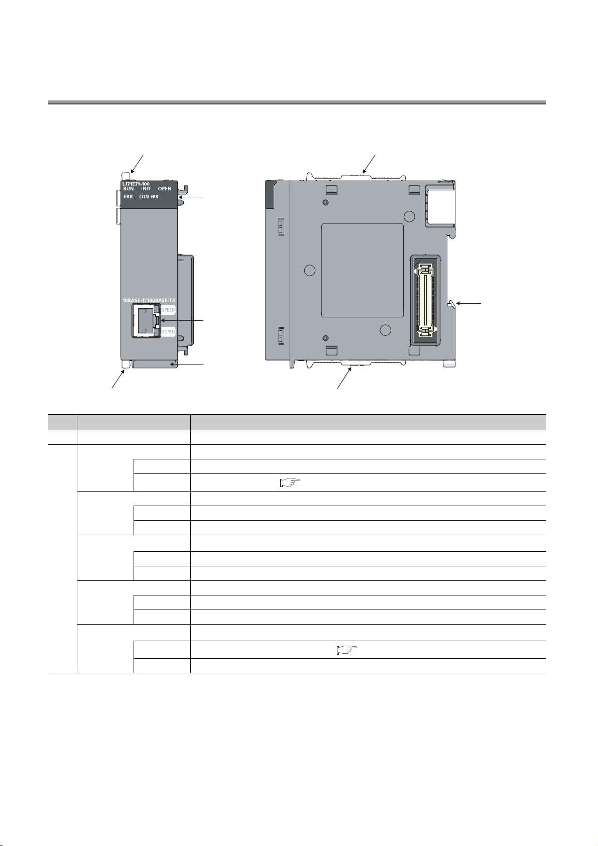
CHAPTER 2 PART NAMES
2)
3)
4)
1) 1)
1)
1)
5)
This chapter describes the E71 parts.
No. Name Application
1) Module joint lever A lever to fix modules
RUN Indicates operating status.
ON In normal operation
OFF
INIT. Indicates initial process status.
ON Normal completion
OFF Not processed
*1
OPEN
2)
ERR. Indicates hardware failure status.
COM.ERR.
ON An open process normally completed (connection open)
OFF An open process normally completed (no connection)
ON A hardware failure has occurred.
OFF Normal
*2
ON
OFF Normal communications in progress
An error has occurred. ( Page 191, Section 14.4.1)
Indicates open process status.
Indicates whether a communication failure has occurred.
A communication failure has occurred. ( Page 191, Section 14.4.2)
24
Page 27

No. Name Application
SPEED Indicates a transmission speed.
ON 100Mbps
OFF 10Mbps or a cable not connected
SD/RD Indicates data communication status.
3)
10BASE-T/100BASE-TX
communication connector
(RJ45)
4) Serial number display A display indicating the serial number printed on the rating plate
5) DIN rail hook A hook to install the module on a DIN rail
*1 The OPEN LED turns on and off depending on the open status of user connections 1 to 16. (The open status of the
*2 If the COM.ERR. LED is on, it does not turn off even if the error cause is eliminated. For how to turn off the LED, refer to
ON Data communications in progress
OFF
system connections (e.g. automatic open UDP port) is not included.)
"How to Turn Off the COM.ERR. LED". ( Page 240, Section 14.10)
Data not sent or not received ( Page 192, Section 14.4.3)
A connector to connect an E71 to the 10BASE-T or 100BASE-TX network (An E71 judges whether
to connect to the 10BASE-T or 100BASE-TX network based on the hub.)
CHAPTER 2 PART NAMES
2
25
Page 28

CHAPTER 3 SPECIFICATIONS
This chapter describes the performance specifications, functions, CPU module I/O signals, and buffer memory areas
of an E71.
3.1 General Specifications
For the general specifications of an E71, refer to the following.
"Safety Guidelines", the manual included with the CPU module
3.2 Performance Specifications
The following table lists the performance specifications of an E71.
Specifications
Item
100BASE-TX 10BASE-T
Data transmission speed 100Mbps 10Mbps
Interface RJ45 (AUTO MDI/MDI-X)
Transmission
specifications
Sending/receiving
data storage
memory
Number of occupied I/O points 32 points (I/O assignment: Intelligent 32 points)
Internal current consumption (5VDC) 0.60A
External dimensions 95 (H) × 28.5 (W) × 90 (D) [mm]
Weight 0.18kg
Communication mode Full-duplex/Half-duplex Half-duplex
Transmission method Base band
Maximum segment length
Maximum number of
cascade connections
Number of simultaneous
open connections
Fixed buffer 1k word × 16
Random access buffer 6k words × 1
E-mail
Attachment 6k words × 1
Main text 960k words × 1
Cascade connection (maximum of 2
100m (length between a hub and a node)
2
levels*
)
16 connections (Connections usable on a program)
LJ71E71-100
*1
Cascade connection (maximum of 4
levels*2)
26
Page 29

Transmission
specifications
sending/receiving
data
*1 For the maximum segment length (a length between hubs), consult with the manufacturer of the switching hub used.
*2 This applies when a repeater hub is used. For the number of levels that can be constructed when a switching hub is
*3 If divided files are received, only the first file is received and the remaining files are discarded.
*4 If an e-mail is sent from a connected device to the programmable controller side, specify the encoding method
CHAPTER 3 SPECIFICATIONS
Specifications
Item
LJ71E71-100
100BASE-TX 10BASE-T
Data size
Data transfer method
Subject Us-ASCII format or ISO-2022-JP (Base64)
Attachment format MIME format
MIME Version 1.0
Data of attachment format
Division of attachment
When sending (encode)
When receiving (decode)
Encryption None
Compression None
Communications with a mail
server
Operation check mailer
used, consult with the manufacturer of the switching hub used.
(Base64/7 bits/8 bits/Quoted Printable) of the attachment.
Attachment 6k words × 1
Main text 960k words × 1
When sending: Send either a file as attachment or main text (select one).
When receiving: Receive a file as attachment.
Can be selected from binary, ASCII, and CSV.
File name: XXXX.bin (binary), XXXX.asc (ASCII), XXXX.csv (CSV)
(CSV: Comma Separated Value)
Cannot be divided (Only one file can be sent/received.)
Subject: Base64/7 bits
Main text: 7 bits
Attachment: Base64
Subject: (Does not decode)
Main text: (Cannot be received)
Attached file: Base64/7 bits/8 bits/Quoted Printable
SMTP (sending server) Port number = 25,
POP3 (receiving server) Port number = 110
Microsoft
®
Corporation Microsoft Office Outlook 2003
3
*3
*4
3.2 Performance Specifications
27
Page 30

3.3 Function List
This section lists the E71 functions.
3.3.1 Function list
The following table lists the functions of the E71.
(1) Basic functions
The following table lists the basic E71 functions explained in this manual.
Function Description Reference
Connecting with MELSOFT products and a
GOT
MC protocol communications
Procedure exists
No procedure
Communications
using a fixed buffer
Communications using a random access
buffer
Router relay function
Communications using an auto-open UDP
port
Remote password Unauthorized remote access to a CPU module is prevented. Page 140, Section 12.3
Hub connection status monitor function
IP address in use detection function
Alive check function
Module error collection function
Pairing open
Broadcast
communications
An E71 can be connected with MELSOFT products, such as a
programming tool and MX Component, and a GOT.
CPU module data can be read/written from/to connected
devices. Access to files can be also performed.
Any data is sent/received between a CPU module and
connected devices using the fixed buffer of an E71.
Paring receiving/sending connections enables data
communications with two connections by performing the open
process for one port.
Broadcast communications are enabled with all E71connected stations in the same Ethernet network that is
connected to the E71 when “No Procedure” communications
using a fixed buffer are performed using UDP/IP.
Data is read/written from multiple connected devices to the
random access buffer of an E71.
Data communications are performed through a router and a
gateway. This function is not the function where an E71
operates as a router.
Communications are enabled without the open/close
processes after an E71-connected station is started up.
The current connection status and transmission speed of an
E71 and a hub and the number of times that the E71 detected
disconnection can be checked.
If different stations in the same network use the same IP
address, the address in use can be detected.
Whether a connected device is normally operating after a
connection is established (open process) can be checked.
An error that has occurred in an E71 can be stored in the CPU
module as error history.
The history data can be stored on a memory with the backup
power feature; therefore, error details are held even if the
CPU module is reset or the system is powered off.
Page 81, CHAPTER 8
Page 84, CHAPTER 9
Page 87, CHAPTER 10
Page 105, Section 10.7
Page 107, Section 10.8
Page 120, CHAPTER 11
Page 135, Section 12.1
Page 139, Section 12.2
Page 150, Section 12.4
Page 151, Section 12.5
Page 153, Section 12.6
Page 190, Section 14.3
28
Page 31

(2) Special functions
The following special functions are also available. For the functions, refer to the following.
MELSEC-Q/L Ethernet Interface Module User's Manual (Application)
Function Description
E-mail function
CC-Link IE Controller Network, CC-Link IE Field
Network, MELSECNET/H, MELSECNET/10 relay
communications
Communications using data link instructions
File transfer (FTP server) function
CHAPTER 3 SPECIFICATIONS
Data are sent/received using an e-mail.
• Data sent/received by a CPU module
• Data sent using the programmable controller CPU monitoring function
(automatic notification function)
Data are communicated over multiple network systems where Ethernet and other
networks exist together or network systems that relay multiple Ethernet networks.
Data of a CPU module in other stations can be read/written over Ethernet using
data link instructions.
Data can be read/written in files from connected devices using an exclusive FTP
command.
3
(3) Web function
This function allows data to be read/written from/to a remote CPU module over the Internet using a Web browser.
For the function, refer to the following.
MELSEC-Q/L Ethernet Interface Module User's Manual (Web function)
3.3.2 Use with other functions
The following table lists the relationships between functions that can be used together.
: Available, ×: Not available or this function does not correspond to the functions in the "Communication function" column.
CC-Link IE Controller
open
×
Communications
using an
auto-open UDP
port
*1
Remote
password
Broadcast
communications
3
*1 *
3 *4
*
Network, CC-Link IE
Communication
function
MC protocol
communications
Communications
using a fixed buffer
Communications
using a random
access buffer
E-mail function × × × × × × × ×
Communications
using data link
instructions
File transfer (FTP
server) function
Web function × × × × ×
Field Network,
MELSECNET/H,
MELSECNET/10 relay
communications
*1 *2
××
××××
×××× ××
Router
relay
function
Alive
check
function
Pairing
×× × ×
Communication
method
TCP/IP UDP/IP
3.3 Function List
3.3.2 Use with other functions
*1 These functions cannot be used with an A-compatible 1E frame.
*2 The auto-open UDP port is excluded.
*3 These functions can be used only for UDP/IP communication.
*4 These functions cannot be used for communications using a fixed buffer in the "Procedure Exist" control method.
29
Page 32

3.4 List of I/O Signals
The following table lists the I/O signals for an E71. The I/O signal assignment of when the start I/O number of an E71 is
0000 is listed below.
Device
number
X0
X1
X2
X3
X4
X5
X6
X7
X8
X9
XA
XB
XC
XD
XE
XF
X10
X11
Signal name
For fixed buffer communication of connection No.1 (ON:
Sending normal completion or reception completion,
OFF: -)
For fixed buffer communication of connection No.1 (ON:
Detection of sending error or reception error, OFF: -)
For fixed buffer communication of connection No.2 (ON:
Sending normal completion or reception completion,
OFF: -)
For fixed buffer communication of connection No.2 (ON:
Detection of sending error or reception error, OFF: -)
For fixed buffer communication of connection No.3 (ON:
Sending normal completion or reception completion,
OFF: -)
For fixed buffer communication of connection No.3 (ON:
Detection of sending error or reception error, OFF: -)
For fixed buffer communication of connection No.4 (ON:
Sending normal completion or reception completion,
OFF: -)
For fixed buffer communication of connection No.4 (ON:
Detection of sending error or reception error, OFF: -)
For fixed buffer communication of connection No.5 (ON:
Sending normal completion or reception completion,
OFF: -)
For fixed buffer communication of connection No.5 (ON:
Detection of sending error or reception error, OFF: -)
For fixed buffer communication of connection No.6 (ON:
Sending normal completion or reception completion,
OFF: -)
For fixed buffer communication of connection No.6 (ON:
Detection of sending error or reception error, OFF: -)
For fixed buffer communication of connection No.7 (ON:
Sending normal completion or reception completion,
OFF: -)
For fixed buffer communication of connection No.7 (ON:
Detection of sending error or reception error, OFF: -)
For fixed buffer communication of connection No.8 (ON:
Sending normal completion or reception completion,
OFF: -)
For fixed buffer communication of connection No.8 (ON:
Detection of sending error or reception error, OFF: -)
Open completed for connection No.1
(ON: Open completion signal, OFF: -)
Open completed for connection No.2
(ON: Open completion signal, OFF: -)
Device
number
Y0
Y1
Y2
Y3
Y4
Y5
Y6
Y7
Y8
Y9
YA
YB
YC
YD
YE
YF
Y10 Use prohibited
Y11 Use prohibited
Connection No.1 (ON: At sending request or reception
complete confirmation signal, OFF: -)
Connection No.2 (ON: At sending request or reception
complete confirmation signal, OFF: -)
Connection No.3 (ON: At sending request or reception
complete confirmation signal, OFF: -)
Connection No.4 (ON: At sending request or reception
complete confirmation signal, OFF: -)
Connection No.5 (ON: At sending request or reception
complete confirmation signal, OFF: -)
Connection No.6 (ON: At sending request or reception
complete confirmation signal, OFF: -)
Connection No.7 (ON: At sending request or reception
complete confirmation signal, OFF: -)
Connection No.8 (ON: At sending request or reception
complete confirmation signal, OFF: -)
Connection No.1
(ON: Open request, OFF: -)
Connection No.2
(ON: Open request, OFF: -)
Connection No.3
(ON: Open request, OFF: -)
Connection No.4
(ON: Open request, OFF: -)
Connection No.5
(ON: Open request, OFF: -)
Connection No.6
(ON
: Open request, OFF: -)
Connection No.7
(ON: Open request, OFF: -)
Connection No.8
(ON: Open request, OFF: -)
Signal name
30
Page 33

CHAPTER 3 SPECIFICATIONS
Remark
Device
number
X12
X13
X14
X15
X16
X17
X18
X19
X1A
X1B Use prohibited Y1B Use prohibited
X1C
X1D Use prohibited Y1D Use prohibited
X1E Use prohibited Y1E Use prohibited
X1F
Open completed for connection No.3
(ON: Open completion signal, OFF: -)
Open completed for connection No.4
(ON: Open completion signal, OFF: -)
Open completed for connection No.5
(ON: Open completion signal, OFF: -)
Open completed for connection No.6
(ON: Open completion signal, OFF: -)
Open completed for connection No.7
(ON: Open completion signal, OFF: -)
Open completed for connection No.8
(ON: Open completion signal, OFF: -)
Open abnormal detection signal
(ON: At off request, OFF: -)
Open abnormal detection signal
(ON: Normal completion, OFF: -)
Open abnormal detection signal
(ON: Abnormal end, OFF: -)
COM.ERR. LED lit confirmation
(ON: lit, OFF: off)
Watchdog timer error detection
(ON: Watchdog timer error, OFF: -)
Signal name
Device
number
Y12 Use prohibited
Y13 Use prohibited
Y14 Use prohibited
Y15 Use prohibited
Y16 Use prohibited
Y17
Y18 Use prohibited
Y19
Y1A Use prohibited
Y1C Use prohibited
Y1F Use prohibited
COM.ERR. LED Off request
(ON: At off request, OFF: -)
Initial request signal
(ON: At request, OFF: -)
Signal name
3
3.4 List of I/O Signals
Do not use any use prohibited signal as an I/O signal to the CPU module. Doing so may cause malfunction of the
programmable controller system.
The I/O signals listed in this section are mainly applied when QnA series module programs are used. For the L series, the
I/O signals for intelligent function modules are turned on and off with dedicated instructions. When QnA series module
programs are used, it is recommended to replace the signals with the dedicated instructions described in the section that
describes the corresponding functions.
31
Page 34

3.5 Buffer Memory
This section describes the E71 buffer memory.
3.5.1 Configuration of the buffer memory
This section describes a buffer memory configuration.
(1) Buffer memory address configuration
A buffer memory area consists of 16 bits per address.
b9b15 b14 b13 b12 b11 b10 b8 b7 b6 b5 b4 b3 b2 b1 b0
(2) Buffer memory area configuration
Buffer memory consists of user areas and system areas.
(a) User areas
A user area is an area where a user writes or reads data. A user area consists of a parameter area for the initial
process and data communications, an area for data communications, and an area to store communication
status and communication error data. Data communications may take long if user areas are used continually;
therefore, use them only when needed.
(b) System areas
A system area is an area used by a system.
Do not write any data to the "system area". Doing so may cause malfunction of the programmable controller system.
32
Page 35

3.5.2 List of buffer memory addresses
The following table lists the buffer memory addresses of an E71.
CHAPTER 3 SPECIFICATIONS
Address
Decimal
(Hexadecimal)
0 and 1
and 1H)
(0
H
2 and 3
and 3H)
(2
H
4
)
(4
H
5 to 10
to AH)
(5
H
11
)
(B
H
12
)
(C
H
13
)
(D
H
14
(E
)
H
15
)
(F
H
16
)
(10
H
17
)
(11
H
18
(12
)
H
19
)
(13
H
Application Name
Own station E71 IP address
System area - -
Special function settings
Router relay function (b5, b4)
• 00: Do not use
•01: Use
Conversion system setting for CC-Link IE Controller
Network, CC-Link IE Field Network, MELSECNET/H,
MELSECNET/10 relay function (b7, b6)
• 00: Automatic response system
• 01: IP address computation system
• 10: Table exchange system
• 11: Use-together system
FTP function setting (b9, b8)
• 00: Do not use
•01: Use
Bits other than those described above are reserved for
system use.
Initial process
parameter
setting area
System area - -
TCP ULP timer value
(Setting time = setting value × 500 ms)
TCP zero window timer value
(Setting time = setting value × 500 ms)
TCP resend timer value
(Setting time = setting value × 500 ms)
TCP end timer value
(Setting time = setting value × 500 ms)
IP assembly timer value
Monitoring
timer
(Setting time = setting value × 500 ms)
Response monitoring timer value
(Setting time = setting value × 500 ms)
Destination existence confirmation starting
interval timer value
(Setting time = setting value × 500 ms)
Destination existence confirmation interval
timer value
(Setting time = setting value × 500 ms)
Destination existence confirmation
resending time
Initial
value
C00001FE
0100
3C
(60)
14
(20)
14
(20)
28
(40)
(10)
3C
(60)
4B0
(1200)
14
(20)
Programming
tool setting
applicability
H
H
H
H
H
H
A
H
H
H
H
3
H
(3)
3
3.5 Buffer Memory
3.5.2 List of buffer memory addresses
33
Page 36

Address
Decimal
(Hexadecimal)
20
)
(14
H
21 to 29
to 1DH)
(15
H
30
(1E
)
H
31
(1F
)
H
Application Name
Initial process
parameter
setting area
Initial process
parameter
setting area (For
reinitialization)
Auto-open UDP port number
System area - -
TCP Maximum Segment Transmission setting area
: Enable TCP Maximum Segment Size Option
•0
H
transmission
: Disable TCP Maximum Segment Size Option
• 8000
H
transmission
Re-initialization makes the set value effective.
Communication condition setting (Ethernet Operation
Setting) area
Communication data code setting (b1)
• 0: Binary Code
• 1: ASCII Code
TCP existence confirmation setting (b4)
• 0: Use the Ping
• 1: Use the KeepAlive
Send frame setting (b5)
• 0: Ethernet
• 1: IEEE 802.3
Setting of write enable/disable at RUN time (b6)
• 0: Disable
• 1: Enable
Initial timing setting (b8)
• 0: Do not wait for OPEN (Communications impossible at
STOP time)
• 1: Always wait for OPEN (Communication possible at
STOP time)
Reinitialization specification (b15)
• 0: Reinitialization process complete (reset by the system)
• 1: Reinitialization process request (set by the user)
Initial
value
1388
8000
Programming
tool setting
applicability
H
H
0
H
×
×
34
Bits other than those described above are reserved for
system use.
Page 37

CHAPTER 3 SPECIFICATIONS
Address
Decimal
(Hexadecimal)
32
)
(20
H
33
)
(21
H
34
)
(22
H
35
)
(23
H
36
)
(24
H
37
)
(25
H
38
)
(26
H
39
)
(27
H
Application Name
Connection No.1
Usage of fixed buffer (b0)
• 0: For sending, or communications
using a fixed buffer are not performed
• 1: For receiving
Destination existence confirmation (b1)
• 0: No confirm
• 1: Confirm
Pairing open (b7)
• 0: Disable
•1: Enable
Communication method (protocol) (b8)
• 0: TCP/IP
• 1: UDP/IP
Communications using a fixed buffer (b9)
• 0: Procedure exists
• 1: No procedure
Open system (b15, b14)
Communication
parameter
setting area
Connection
usage setting
area
• 00: Active open or UDP/IP
• 10: Unpassive open
• 11: Fullpassive open
Bits other than those described above are
reserved for system use.
Connection No.2 (The bit configuration is the same as Connection No.1.)
Connection No.3 (The bit configuration is the same as Connection No.1.)
Connection No.4 (The bit configuration is the same as Connection No.1.)
Connection No.5 (The bit configuration is the same as Connection No.1.)
Connection No.6 (The bit configuration is the same as Connection No.1.)
Connection No.7 (The bit configuration is the same as Connection No.1.)
Connection No.8 (The bit configuration is the same as Connection No.1.)
Initial
value
Programming
tool setting
applicability
0
H
3
3.5 Buffer Memory
3.5.2 List of buffer memory addresses
35
Page 38

Address
Decimal
(Hexadecimal)
40
)
(28
H
41 and 42
and 2AH)
(29
H
43
)
(2B
H
44 to 46
to 2EH)
(2C
H
47 to 53
to 35H)
(2F
H
54 to 60
to 3CH)
(36
H
61 to 67
to 43H)
(3D
H
68 to 74
to 4AH)
(44
H
75 to 81
to 51H)
(4B
H
82 to 88
to 58H)
(52
H
89 to 95
to 5FH)
(59
H
96 to 102
to 66H)
(60
H
103 and 104
and 68H)
(67
H
105
)
(69
H
106 and 107
and 6BH)
(6A
H
108 to 110
to 6EH)
(6C
H
111 t o 11 5
to 73H)
(6F
H
116
)
(74
H
117
)
(75
H
118
(76
)
H
119
(77
)
H
Application Name
Connection
No.1
Connection No.2 (The bit configuration is the same as Connection No.1.)
Communication
Communication
parameter
setting area
Communication
status storage
area
address setting
area
System area - -
System area - -
Area for the
initial process
Connection No.3 (The bit configuration is the same as Connection No.1.)
Connection No.4 (The bit configuration is the same as Connection No.1.)
Connection No.5 (The bit configuration is the same as Connection No.1.)
Connection No.6 (The bit configuration is the same as Connection No.1.)
Connection No.7 (The bit configuration is the same as Connection No.1.)
Connection No.8 (The bit configuration is the same as Connection No.1.)
Initial error code
Own station IP address
Own station MAC address
System area - -
Auto-open UDP port number
System area - -
Station number (b0 to b7)
Network number of the own station (b8 to
b15)
Own station group number
Own station port No.
Destination IP address
Destination Port No.
Destination MAC address
Initial
value
0
0
0
FFFFFFFFF
FFF
0
0
0
0
0
0
Programming
tool setting
applicability
H
H
H
H
H
H
H
H
H
H
×
×
×
×
×
×
×
36
Page 39

CHAPTER 3 SPECIFICATIONS
Address
Decimal
(Hexadecimal)
120
)
(78
H
121 and 122
and 7AH)
(79
H
123
)
(7B
H
124
)
(7C
H
125
)
(7D
H
126
)
(7E
H
127
)
(7F
H
128
)
(80
H
129
)
(81
H
130 to 139
to 8BH)
(82
H
140 to 149
to 95H)
(8C
H
150 to 159
to 9FH)
(96
H
160 to 169
to A9H)
(A0
H
170 to 179
to B3H)
(AA
H
180 to 189
to BDH)
(B4
H
190 to 199
to C7H)
(BE
H
Application Name
Connection
No.1
Communication
status storage
area
Connection
information
area
Connection No.2 (The bit configuration is the same as Connection No.1.)
Connection No.3 (The bit configuration is the same as Connection No.1.)
Connection No.4 (The bit configuration is the same as Connection No.1.)
Connection No.5 (The bit configuration is the same as Connection No.1.)
Connection No.6 (The bit configuration is the same as Connection No.1.)
Connection No.7 (The bit configuration is the same as Connection No.1.)
Connection No.8 (The bit configuration is the same as Connection No.1.)
Own station port No.
Destination IP address
Destination Port No.
Open error code
Fixed buffer sending error
code
Connection end code
Fixed buffer communication
time (Maximum value)
Fixed buffer communication
time (Minimum value)
Fixed buffer communication
time (Current value)
Initial
value
Programming
tool setting
applicability
0
H
0
H
0
H
0
H
0
H
0
H
0
H
0
H
0
H
×
×
×
3
×
×
×
×
×
×
3.5 Buffer Memory
3.5.2 List of buffer memory addresses
37
Page 40

Address
Decimal
(Hexadecimal)
200
)
(C8
H
Application Name
LED on/off status (Stores the on/off status
of the LEDs on the front of the Ethernet
module)
INIT. LED (b0)
•0: OFF
• 1: ON (initial process completed)
OPEN LED (b1)
•0: OFF
• 1: ON (connection open processing
completed)
ERR. LED (b3)
•0: OFF
• 1: ON (hardware failure)
COM.ERR. LED (b4)
•0: OFF
• 1: ON (communication error)
Initial
value
Programming
tool setting
applicability
0
H
×
201
(C9
202
(CA
Communication
status storage
area
)
H
)
H
Area for
module status
Bits other than those described above are
reserved for system use.
Hub connection status area
Communication mode (b9)
• 0: Half duplex
• 1: Full duplex
Hub connection status (b10)
• 0: Hub not connected/disconnected
• 1: Hub connected
Data transmission speed (b15, b14)
• 00: Operating at 10BASE-T
• 01: Operating at 100BASE-TX
Bits other than those described above are
reserved for system use.
Switch status (operational mode setting)
Communication data code setting
•0: Online
• 1: Offline
• 2: Self-loopback test
• 3: Hardware test
0
H
0
H
×
38
Page 41

CHAPTER 3 SPECIFICATIONS
Address
Decimal
(Hexadecimal)
203
)
(CB
H
Application Name
Status of settings with a programming tool
Communication data code setting (b1)
• 0: Communications in a binary code
• 1: Communications in an ASCII code
Initial/open method setting (b2)
• 0: No parameter setting (start up
according to the program)
• 1: Parameter setting (start up according
to the parameters)
TCP Existence confirmation setting (b4)
• 0: Use the Ping
• 1: Use the KeepAlive
Send frame setting (b5)
Module status
area
Communication
status storage
area
• 0: Ethernet
• 1: IEEE 802.3
Setting of write enable/disable at RUN
time (b6)
• 0: Disable
•1: Enable
Initial timing setting (b8)
• 0: Do not wait for OPEN
(Communications impossible at STOP
time)
• 1: Always wait for OPEN
(Communication possible at STOP time)
Initial
value
Programming
tool setting
applicability
0
H
3
204
(CC
205
(CD
206
(CE
207
(CF
208
(D0
209
(D1
210 to 223
to DFH)
(D2
H
224 to 226
(E0
to E2H)
H
227
(E3
228
(E4
Bits other than those described above are
reserved for system use.
)
H
)
H
)
H
Area for
sending/
)
H
receiving
instructions
)
H
)
H
System area - -
RECV instruction execution request
0
H
System area - -
0
H
0
H
Data link
instruction
execution
result
ZNRD instruction
System area - -
ZNWR instruction
×
×
×
3.5 Buffer Memory
3.5.2 List of buffer memory addresses
System area - -
System area - -
)
H
)
H
Error log area
Number of errors
Error log write pointer
0
H
0
H
×
×
39
Page 42

Address
Decimal
(Hexadecimal)
229
)
(E5
H
230
)
(E6
H
231
)
(E7
H
232
)
(E8
H
233
)
(E9
H
234 and 235
and EBH)
(EA
H
236
)
(EC
H
237
)
(ED
H
238 to 246
to F6H)
(EE
H
247 to 255
to FFH)
(F7
H
256 to 264
to 108H)
(100
H
265 to 273
to 111H)
(109
H
274 to 282
to 11AH)
(112
H
283 to 291
to 123H)
(11B
H
292 to 300
to 12CH)
(124
H
301 to 309
to 135H)
(12D
H
310 to 318
to 13EH)
(136
H
319 to 327
to 147H)
(13F
H
328 to 336
to 150H)
(148
H
337 to 345
to 159H)
(151
H
346 to 354
to 162H)
(15A
H
355 to 363
to 16BH)
(163
H
364 to 372
to 174H)
(16C
H
Application Name
Error log
block 1
Error log block 2 (The bit configuration is the same as Error log block 1.)
Error log block 3 (The bit configuration is the same as Error log block 1.)
Error log block 4 (The bit configuration is the same as Error log block 1.)
Error log area
Error log block
area
Error log block 5 (The bit configuration is the same as Error log block 1.)
Error log block 6 (The bit configuration is the same as Error log block 1.)
Error log block 7 (The bit configuration is the same as Error log block 1.)
Error log block 8 (The bit configuration is the same as Error log block 1.)
Error log block 9 (The bit configuration is the same as Error log block 1.)
Error log block 10 (The bit configuration is the same as Error log block 1.)
Error log block 11 (The bit configuration is the same as Error log block 1.)
Error log block 12 (The bit configuration is the same as Error log block 1.)
Error log block 13 (The bit configuration is the same as Error log block 1.)
Error log block 14 (The bit configuration is the same as Error log block 1.)
Error log block 15 (The bit configuration is the same as Error log block 1.)
Error log block 16 (The bit configuration is the same as Error log block 1.)
Initial
value
Error code/end code
Subheader
Command code
Connection No.
Own station port No.
Destination IP address
Destination Port No.
Programming
tool setting
applicability
0
H
0
H
0
H
0
H
0
H
0
H
0
H
System area - -
×
×
×
×
×
×
×
40
Page 43

CHAPTER 3 SPECIFICATIONS
Address
Decimal
(Hexadecimal)
373 to 375
to 177H)
(175
H
376 and 377
and 179H)
(178
H
378 and 379
(17A
and 17BH)
H
380 and 381
(17C
and 17DH)
H
382 to 407
to 197H)
(17E
H
408 and 409
and 199H)
(198
H
410 and 411
(19A
and 19BH)
H
412 and 413
(19C
and 19DH)
H
414 and 415
(19E
and 19FH)
H
416 and 417
(1A0
and 1A1H)
H
418 and 419
and 1A3H)
(1A2
H
420 and 421
and 1A5H)
(1A4
H
422 to 439
to 1B7H)
(1A6
H
440 and 441
and 1B9H)
(1B8
H
442 and 443
(1BA
and 1BBH)
H
444 and 445
(1BC
and 1BDH)
H
446 to 471
to 1D7H)
(1BE
H
472 and 473
and 1D9H)
(1D8
H
474 and 475
(1DA
and 1DBH)
H
476 and 477
(1DC
and 1DDH)
H
478 to 481
to 1E1H)
(1DE
H
Programming
tool setting
applicability
Application Name
Initial
value
System area --
Received IP packet count
0
H
×
Received IP packet count
discarded due to sumcheck
IP
error
Sent IP packet total count
0
H
0
H
×
×
System area - -
Received ICMP packet
count
0
H
×
Received ICMP packet
count discarded due to sum
0
H
×
check error
Sent ICMP packet total
count
0
H
×
Echo request total count of
Error log area
Status for each
protocol
ICMP
received
ICMP packets
Echo reply total count of
sent ICMP packets
Echo request total count of
sent ICMP packets
Echo reply total count of
received ICMP packets
0
H
0
H
0
H
0
H
×
×
×
×
System area - -
Received TCP packet count
0
H
×
Received TCP packet count
TCP
discarded due to sum check
error
Sent TCP packet total count
0
H
0
H
×
×
System area - -
Received UDP packet count
0
H
×
Received UDP packet count
UDP
discarded
due to sum check error
Sent UDP packet total count
0
H
0
H
×
×
System area - -
3
3.5 Buffer Memory
3.5.2 List of buffer memory addresses
41
Page 44

Address
Decimal
(Hexadecimal)
482 to 511
to 1FFH)
(1E2
H
512 and 513
and 201H)
(200
H
514 and 515
and 203H)
(202
H
516
)
(204
H
517 and 518
and 206H)
(205
H
519 and 520
and 208H)
(207
H
521 to 524
to 20CH)
(209
H
525 to 528
to 210H)
(20D
H
529 to 532
to 214H)
(211
H
533 to 536
to 218H)
(215
H
537 to 540
to 21CH)
(219
H
541 to 544
to 220H)
(21D
H
545 to 548
to 224H)
(221
H
549
)
(225
H
Application Name
Error log area
Router relay
parameter
setting area
Status for each
protocol
System area - -
Sub-net mask
Default router IP address
Number of registered routers
Sub-net address
Router 1
Router IP address
Router 2 (The bit configuration is the same as Router 1.)
Router 3 (The bit configuration is the same as Router 1.)
Router 4 (The bit configuration is the same as Router 1.)
Router 5 (The bit configuration is the same as Router 1.)
Router 6 (The bit configuration is the same as Router 1.)
Router 7 (The bit configuration is the same as Router 1.)
Router 8 (The bit configuration is the same as Router 1.)
System area - -
Initial
value
Programming
tool setting
applicability
0
H
0
H
0
H
0
H
0
H
42
Page 45

CHAPTER 3 SPECIFICATIONS
Address
Decimal
Application Name
(Hexadecimal)
550 and 551
and 227H)
(226
H
552
)
(228
H
553 and 554
and 22AH)
(229
H
555 and 556
and 22CH)
(22B
H
557 and 558
and 22EH)
(22D
H
559 to 564
to 234H)
(22F
H
Station No.
<-> IP
information
setting area
to to
931 to 936
to 3A8H)
(3A3
H
937 and 938
and 3AAH)
(3A9
H
939 to 943
to 3AFH)
(3AB
H
944 to 949
to 3B5H)
(3B0
H
950 to 953
to 3B9H)
(3B6
H
954
(3BA
)
H
FTP setting area
955
)
(3BB
H
956 to 1663
to 67FH)
(3BC
H
System area - -
Number of conversion table data
Communication request
destination/source stations network
Conversion
information
No.1
number and station number
External station Ethernet module IP
address
System area - -
Conversion information No.2
(The bit configuration is the same as Conversion information No.1.)
Conversion information No.64
(The bit configuration is the same as Conversion information No.1.)
Subnet mask pattern for CC-Link IE Controller Network, CCLink IE Field Network, MELSECNET/H, and
MELSECNET/10 routing
System area - -
FTP login name "LJ71E71"
Password "LJ71E71"
Command input monitoring timer
Programmable controller CPU monitoring timer
System area - -
Initial
value
708
Programming
tool setting
applicability
0
H
0
H
0
H
0
H
H
A
H
3
3.5 Buffer Memory
3.5.2 List of buffer memory addresses
43
Page 46

Address
Decimal
(Hexadecimal)
1664
)
(680
H
1665 to 2687
to A7FH)
(681
H
2688 to 3711
to E7FH)
(A80
H
3712 to 4735
to 127FH)
(E80
H
4736 to 5759
to 167FH)
(1280
H
5760 to 6783
to 1A7FH)
(1680
H
6784 to 7807
to 1E7FH)
(1A80
H
7808 to 8831
to 227FH)
(1E80
H
8832 to 9855
to 267FH)
(2280
H
9856 to 16383
to 3FFFH)
(2680
H
16384 to 20479
to 4FFFH)
(4000
H
Application Name
Data length
Fixed buffer data
Fixed buffer data
area
Shared area for
random access
buffers and
e-mail buffers
Fixed buffer
No.1
Fixed buffer No.2 (The bit configuration is the same as Fixed buffer No.1.)
Fixed buffer No.3 (The bit configuration is the same as Fixed buffer No.1.)
Fixed buffer No.4 (The bit configuration is the same as Fixed buffer No.1.)
Fixed buffer No.5 (The bit configuration is the same as Fixed buffer No.1.)
Fixed buffer No.6 (The bit configuration is the same as Fixed buffer No.1.)
Fixed buffer No.7 (The bit configuration is the same as Fixed buffer No.1.)
Fixed buffer No.8 (The bit configuration is the same as Fixed buffer No.1.)
Shared area for random access buffers and e-mail buffers
System area - -
Initial
value
Programming
tool setting
applicability
0
H
0
H
0
H
×
×
×
44
Page 47

CHAPTER 3 SPECIFICATIONS
Address
Decimal
(Hexadecimal)
20480
)
(5000
H
20481
)
(5001
H
20482
)
(5002
H
20483 and 20484
and 5004H)
(5003
H
20485
)
(5005
H
20486
)
(5006
H
20487
(5007
)
H
Application Name
Open completion signal
• 0: Open incomplete
• 1: Open completed
Connection No.1 (b0)
Connection No.2 (b1)
Connection No.16 (b15)
Connection
status storage
area
System port
information area
Connection
status
information
area
Fixed buffer
information
area
Remote
password
status storage
area
Remote
password
status storage
area
System area - -
Open request signal
• 0: No open request
• 1: Open being requested
Connection No.1 (b0)
Connection No.2 (b1)
to
Connection No.16 (b15)
System area - -
Fixed buffer reception status signal
• 0: Data not received
• 1: Data being received
Connection No.1 (b0)
Connection No.2 (b1)
to
Connection No.16 (b15)
Remote password status
• 0: Unlock status/no remote password
setting
• 1: Lock status
Connection No.1 (b0)
Connection No.2 (b1)
to
Connection No.16 (b15)
Remote password status
• 0: Unlock status/no remote password
setting
• 1: Lock status
• Auto-open UDP port (b0)
• MELSOFT application transmission port
(UDP) (b1)
• MELSOFT application transmission port
(TCP) (b2)
• FTP transmission port (b3)
to
Initial
value
Programming
tool setting
applicability
0
H
0
H
0
H
0
H
0
H
×
3
×
×
3.5 Buffer Memory
3.5.2 List of buffer memory addresses
×
×
45
Page 48

Address
Decimal
(Hexadecimal)
20488
)
(5008
H
20489 to 20591
to 506FH)
(5009
H
20592
(5070
)
H
20593
)
(5071
H
20594
(5072
)
H
20595
(5073
)
H
20596
)
(5074
H
20597
)
(5075
H
20598
)
(5076
H
20599 to 20603
to 507BH)
(5077
H
20604 to 20608
to 5080H)
(507C
H
20609 to 20613
to 5085H)
(5081
H
20614 to 20618
to 508AH)
(5086
H
20619 to 20623
to 508FH)
(508B
H
20624 to 20628
to 5094H)
(5090
H
Application Name
System port use prohibited designation
• 0: Use allowed
• 1: Use prohibited
• Auto-open UDP port (b0)
• MELSOFT application transmission port
(UDP) (b1)
• MELSOFT application transmission port
(TCP) (b2)
System area - -
Remote password mismatch notification
accumulated count designation (For user
open port)
• 0: No designation
• 1 or higher: Notification accumulated
count
Remote password mismatch notification
accumulated count designation (For autoopen UDP port, MELSOFT application
transmission port (TCP/ UDP) and FTP
transmission port)
• 0: No designation
• 1 or higher: Notification accumulated
count
Connection
No.1
Connection No.2 (The bit configuration is the same as Connection No.1.)
Connection No.3 (The bit configuration is the same as Connection No.1.)
Connection No.4 (The bit configuration is the same as Connection No.1.)
Connection No.5 (The bit configuration is the same as Connection No.1.)
Connection No.6 (The bit configuration is the same as Connection No.1.)
Connection No.7 (The bit configuration is the same as Connection No.1.)
System port
information area
Monitoring area
System port
use prohibited
designation
area
Remote
password
function
monitoring area
Accumulated count of
unlock process normal
completion
Accumulated count of
unlock process abnormal
end
Accumulated count of lock
process normal completion
Accumulated count of lock
process abnormal end
Accumulated count of lock
process based on close
Initial
value
Programming
tool setting
applicability
0
H
1
H
2
H
0
H
0
H
0
H
0
H
0
H
×
×
×
×
×
×
×
×
46
Page 49

CHAPTER 3 SPECIFICATIONS
Address
Decimal
(Hexadecimal)
20629 to 20633
to 5099H)
(5095
H
20634 to 20638
to 509EH)
(509A
H
20639 to 20643
to 50A3H)
(509F
H
20644 to 20648
to 50A8H)
(50A4
H
20649 to 20653
to 50ADH)
(50A9
H
20654 to 20658
to 50B2H)
(50AE
H
20659 to 20663
to 50B7H)
(50B3
H
20664 to 20668
to 50BCH)
(50B8
H
20669 to 20673
to 50C1H)
(50BD
H
20674 to 20678
to 50C6H)
(50C2
H
20679 to 20683
to 50CBH)
(50C7
H
20684 to 20688
to 50D0H)
(50CC
H
20689 to 20693
to 50D5H)
(50D1
H
Application Name
Connection No.8 (The bit configuration is the same as Connection No.1.)
Connection No.9 (The bit configuration is the same as Connection No.1.)
Connection No.10 (The bit configuration is the same as Connection No.1.)
Connection No.11 (The bit configuration is the same as Connection No.1.)
Connection No.12 (The bit configuration is the same as Connection No.1.)
Connection No.13 (The bit configuration is the same as Connection No.1.)
Connection No.14 (The bit configuration is the same as Connection No.1.)
Connection No.15 (The bit configuration is the same as Connection No.1.)
Connection No.16 (The bit configuration is the same as Connection No.1.)
Auto-open UDP port
(The bit configuration is the same as Connection No.1.)
MELSOFT application transmission port (UDP)
(The bit configuration is the same as Connection No.1.)
MELSOFT application transmission port (TCP)
(The bit configuration is the same as Connection No.1.)
FTP transmission port
(The bit configuration is the same as Connection No.1.)
Monitoring area
Remote
password
function
monitoring area
Initial
value
Programming
tool setting
applicability
3
3.5 Buffer Memory
3.5.2 List of buffer memory addresses
47
Page 50

Address
Decimal
(Hexadecimal)
20694 to 20736
to 5100H)
(50D6
H
20737
)
(5101
H
20738
)
(5102
H
20739
)
(5103
H
20740
)
(5104
H
20741
)
(5105
H
20742
)
(5106
H
20743
)
(5107
H
20744
)
(5108
H
20745 and 20746
and 510AH)
(5109
H
20747 to 20750
to 510EH)
(510B
H
20751 to 20757
to 5115H)
(510F
H
20758 to 20764
to 511CH)
(5116
H
20765 to 20771
to 5123H)
(511D
H
20772 to 20778
to 512AH)
(5124
H
20779 to 20785
to 5131H)
(512B
H
20786 to 20792
to 5138H)
(5132
H
20793 to 20799
to 513FH)
(5139
H
20800 to 20806
to 5146H)
(5140
H
20807 to 20813
to 514DH)
(5147
H
20814 to 20820
to 5154H)
(514E
H
20821 to 20827
to 515BH)
(5155
H
20828 to 20834
to 5162H)
(515C
H
Application Name
System area - -
Error log pointer
Log counter
(HTTP response code 100 to 199)
Log counter
(HTTP response code 200 to 299)
Log counter
(HTTP response code 300 to 399)
Log counter
(HTTP response code 400 to 499)
Log counter
(HTTP response code 500 to 599)
System area - -
HTTP response code
HTTP status
storage area
Error log block
1
Error log block 2 (The bit configuration is the same as Error log block 1.)
Error log block 3 (The bit configuration is the same as Error log block 1.)
Error log block 4 (The bit configuration is the same as Error log block 1.)
Error log block 5 (The bit configuration is the same as Error log block 1.)
Error log block 6 (The bit configuration is the same as Error log block 1.)
Error log block 7 (The bit configuration is the same as Error log block 1.)
Error log block 8 (The bit configuration is the same as Error log block 1.)
Error log block 9 (The bit configuration is the same as Error log block 1.)
Error log block 10 (The bit configuration is the same as Error log block 1.)
Error log block 11 (The bit configuration is the same as Error log block 1.)
Error log block 12 (The bit configuration is the same as Error log block 1.)
Error log block 13 (The bit configuration is the same as Error log block 1.)
Destination IP address
Error time
Initial
value
Programming
tool setting
applicability
0
H
0
H
0
H
0
H
0
H
0
H
0
H
0
H
0
H
×
×
×
×
×
×
×
×
×
48
Page 51

CHAPTER 3 SPECIFICATIONS
Address
Decimal
(Hexadecimal)
20835 to 20841
to 5169H)
(5163
H
20842 to 20848
to 5170H)
(516A
H
20849 to 20855
to 5177H)
(5171
H
20856 to 20994
to 5202H)
(5178
H
20995
(5203
)
H
20996 to 21119
(5204
to 527FH)
H
21120
(5280
)
H
21121 to 21123
to 5283H)
(5281
H
21124 to 21126
(5284
to 5286H)
H
21127 to 22559
(5287
to 581FH)
H
Application Name
Error log block 14 (The bit configuration is the same as Error log block 1.)
HTTP status
storage area
Use prohibited System area - -
Disconnection
detection storage
area
System area --
IP address
status storage
area
System area --
Error log block 15 (The bit configuration is the same as Error log block 1.)
Error log block 16 (The bit configuration is the same as Error log block 1.)
Disconnection detection count
Same IP address detection flag
• 0: Unique IP addresses
• 1: Same IP address for multiple stations
The MAC address of the station that has been already
connected to the network (The address is stored in the
station with the same IP address.)
The MAC address of the station with the IP address used for
another station (The address is stored in the station that has
been already connected to the network.)
Initial
value
FFFFFFFFF
FFFFFFFFF
Programming
tool setting
applicability
0
H
0×
FFF
H
FFF
H
×
×
×
3
3.5 Buffer Memory
3.5.2 List of buffer memory addresses
49
Page 52

Address
Decimal
(Hexadecimal)
22560
)
(5820
H
22561 and 22562
and 5822H)
(5821
H
22563
)
(5823
H
22564
)
(5824
H
22565
)
(5825
H
22566
)
(5826
H
22567
)
(5827
H
22568
)
(5828
H
22569
)
(5829
H
22570 to 22579
to 5833H)
(582A
H
22580 to 22589
to 583DH)
(5834
H
22590 to 22599
to 5847H)
(583E
H
22600 to 22609
to 5851H)
(5848
H
22610 to 22619
to 585BH)
(5852
H
22620 to 22629
to 5865H)
(585C
H
22630 to 22639
to 586FH)
(5866
H
Application Name
Connection
No.9
Communication
status storage
area
Connection
information
area
Connection No.10 (The bit configuration is the same as Connection No.9.)
Connection No.11 (The bit configuration is the same as Connection No.9.)
Connection No.12 (The bit configuration is the same as Connection No.9.)
Connection No.13 (The bit configuration is the same as Connection No.9.)
Connection No.14 (The bit configuration is the same as Connection No.9.)
Connection No.15 (The bit configuration is the same as Connection No.9.)
Connection No.16 (The bit configuration is the same as Connection No.9.)
Own station port No.
Destination IP address
Destination Port No.
Open error code
Fixed buffer sending error
code
Connection end code
Fixed buffer communication
time (Maximum value)
Fixed buffer communication
time (Minimum value)
Fixed buffer communication
time (Current value)
Initial
value
Programming
tool setting
applicability
0
H
0
H
0
H
0
H
0
H
0
H
0
H
0
H
0
H
×
×
×
×
×
×
×
×
×
50
Page 53

CHAPTER 3 SPECIFICATIONS
Address
Decimal
(Hexadecimal)
22640
)
(5870
H
22641
)
(5871
H
22642
)
(5872
H
22643
)
(5873
H
22644
)
(5874
H
22645
)
(5875
H
22646
)
(5876
H
22647
)
(5877
H
22648
)
(5878
H
22649
)
(5879
H
22650
)
(587A
H
22651 to 22658
to 5882H)
(587B
H
22659 to 22662
to 5886H)
(5883
H
22663 to 22692
to 58A4H)
(5887
H
Application Name
Number of mails remaining on the server
Dedicated instruction normal completion
count
Dedicated instruction abnormal end count
Normal receiving count
Attached file receiving count
Server inquiry count
E-mail status
storage area
Receive
Server communication error count
Error log write count
Receiving error log write pointer
Error log
block 1
Error code
Command code
From
Date
Subject
Initial
value
Programming
tool setting
applicability
0
H
0
H
0
H
0
H
0
H
0
H
0
H
0
H
0
H
0
H
0
H
0
H
0
H
0
H
×
×
×
3
×
×
×
×
×
×
×
×
×
3.5 Buffer Memory
3.5.2 List of buffer memory addresses
×
×
51
Page 54

Address
Decimal
(Hexadecimal)
22693 to 22736
to 58D0H)
(58A5
H
22737 to 22780
to 58FCH)
(58D1
H
22781 to 22824
to 5928H)
(58FD
H
22825 to 22868
to 5954H)
(5929
H
22869 to 22912
to 5980H)
(5955
H
22913 to 22956
to 59ACH)
(5981
H
22957 to 23000
to 59D8H)
(59AD
H
23001 to 23044
to 5A04H)
(59D9
H
23045 to 23088
to 5A30H)
(5A05
H
23089 to 23132
to 5A5CH)
(5A31
H
23133 to 23176
to 5A88H)
(5A5D
H
23177 to 23220
to 5AB4H)
(5A89
H
23221 to 23264
to 5AE0H)
(5AB5
H
23265 to 23308
to 5B0CH)
(5AE1
H
23309 to 23352
to 5B38H)
(5B0D
H
23353
)
(5B39
H
23354
)
(5B3A
H
23355
)
(5B3B
H
23356
)
(5B3C
H
23357
)
(5B3D
H
23358
)
(5B3E
H
23359
)
(5B3F
H
23360
)
(5B40
H
Application Name
Error log block 2 (The bit configuration is the same as Error log block 1.)
Error log block 3 (The bit configuration is the same as Error log block 1.)
Error log block 4 (The bit configuration is the same as Error log block 1.)
Error log block 5 (The bit configuration is the same as Error log block 1.)
Error log block 6 (The bit configuration is the same as Error log block 1.)
Error log block 7 (The bit configuration is the same as Error log block 1.)
Error log block 8 (The bit configuration is the same as Error log block 1.)
Receive
E-mail status
storage area
Send
Error log block 9 (The bit configuration is the same as Error log block 1.)
Error log block 10 (The bit configuration is the same as Error log block 1.)
Error log block 11 (The bit configuration is the same as Error log block 1.)
Error log block 12 (The bit configuration is the same as Error log block 1.)
Error log block 13 (The bit configuration is the same as Error log block 1.)
Error log block 14 (The bit configuration is the same as Error log block 1.)
Error log block 15 (The bit configuration is the same as Error log block 1.)
Error log block 16 (The bit configuration is the same as Error log block 1.)
Dedicated instruction normal completion
count
Dedicated instruction abnormal end count
Number of mails normally completed
Attached file sending count
Sending to the server count
Number of mails abnormally completed
Error log write count
Sending error log write pointer
Initial
value
Programming
tool setting
applicability
0
H
0
H
0
H
0
H
0
H
0
H
0
H
0
H
×
×
×
×
×
×
×
×
52
Page 55

CHAPTER 3 SPECIFICATIONS
Address
Decimal
(Hexadecimal)
23361
)
(5B41
H
23362
)
(5B42
H
23363 to 23370
to 5B4AH)
(5B43
H
23371 to 23374
to 5B4EH)
(5B4B
H
23375 to 23404
to 5B6CH)
(5B4F
H
23405 to 23448
to 5B98H)
(5B6D
H
23449 to 23492
to 5BC4H)
(5B99
H
23493 to 23536
to 5BF0H)
(5BC5
H
23537 to 23580
to 5C1CH)
(5BF1
H
23581 to 23624
to 5C48H)
(5C1D
H
23625 to 23668
to 5C74H)
(5C49
H
23669 to 23712
to 5CA0H)
(5C75
H
23713 to 24575
to 5FFFH)
(5CA1
H
24576
)
(6000
H
24577 to 25599
to 63FFH)
(6001
H
25600 to 26623
to 67FFH)
(6400
H
26624 to 27647
to 6BFFH)
(6800
H
27648 to 28671
to 6FFFH)
(6C00
H
28672 to 29695
to 73FFH)
(7000
H
29696 to 30719
to 77FFH)
(7400
H
30720 to 31743
to 7BFFH)
(7800
H
31744 to 32767
to 7FFFH)
(7C00
H
Application Name
Error log
block 1
Error log block 2 (The bit configuration is the same as Error log block 1.)
E-mail status
storage area
Fixed buffer data
area
Send
Error log block 3 (The bit configuration is the same as Error log block 1.)
Error log block 4 (The bit configuration is the same as Error log block 1.)
Error log block 5 (The bit configuration is the same as Error log block 1.)
Error log block 6 (The bit configuration is the same as Error log block 1.)
Error log block 7 (The bit configuration is the same as Error log block 1.)
Error log block 8 (The bit configuration is the same as Error log block 1.)
System area - -
Fixed buffer
No.9
Data length
Fixed buffer data
Fixed buffer No.10 (The bit configuration is the same as Fixed buffer No.9.)
Fixed buffer No.11 (The bit configuration is the same as Fixed buffer No.9.)
Fixed buffer No.12 (The bit configuration is the same as Fixed buffer No.9.)
Fixed buffer No.13 (The bit configuration is the same as Fixed buffer No.9.)
Fixed buffer No.14 (The bit configuration is the same as Fixed buffer No.9.)
Fixed buffer No.15 (The bit configuration is the same as Fixed buffer No.9.)
Fixed buffer No.16 (The bit configuration is the same as Fixed buffer No.9.)
Error code
Command code
To
Date
Subject
Initial
value
Programming
tool setting
applicability
0
H
0
H
0
H
0
H
0
H
0
H
0
H
×
×
×
3
×
×
3.5 Buffer Memory
3.5.2 List of buffer memory addresses
×
×
53
Page 56

Restarting the CPU module
Reflect the parameter settings by turning off and on the CPU
module or resetting the CPU module.
Setting parameters
Set the following parameters, which are required to start up
the E71, from the programming tool.
Basic setting
Ethernet operation setting
Network diagnostics
Check that the cables are connected properly or that
communications are performed properly with the set
parameters. (PING test, loopback test)
Checkbox
Design the system configuration of the E71.
System consideration
Installation
Connect the E71.
Wiring
Connect an Ethernet cable to the E71.
Continued to COMMUNICATION PROCEDURE
Page 24, CHAPTER 2,
Page 59, Section 6.1
Page 57, Section 5.2,
Page 60, Section 6.2
Page 64, Section 7.1.2,
Page 65, Section 7.1.3
MELSEC-L CPU Module User's Manual
(Hardware Design, Maintenance and
Inspection)
Page 256, Appendix 4
Page 62, CHAPTER 7
Page 26, CHAPTER 3,
Page 56, CHAPTER 5
CHAPTER 4 PROCEDURES BEFORE OPERATION
This chapter describes how to connect an E71 to Ethernet. For how to communicate with connected devices after the
E71 is connected, refer to the communication procedure. ( Page 62, CHAPTER 7)
54
Page 57

Memo
CHAPTER 4 PROCEDURES BEFORE OPERATION
4
55
Page 58

CHAPTER 5 SYSTEM CONFIGURATION
Power supply module CPU module
Display unit
(optional)
I/O modules
or
intelligent function modules END coverE71
5.1 Overall System Configuration
The following is a system configuration example of when using an E71.
56
Page 59

5.2 Network Components
Remark
This section describes the devices used for Ethernet.
CHAPTER 5 SYSTEM CONFIGURATION
E71
Hub
An E71 determines whether to use 100BASE-TX or 10BASE-T and the full-duplex or half-duplex transmission mode
according to the hub. For connection to a hub without the automatic negotiation function, set the half-duplex mode on the
hub side.
Connected device
(1) 100BASE-TX connection
To configure a system for 100BASE-TX connection, use devices that meet the IEEE 802.3 100 BASE-TX
standards.
Configuration device Description
Shielded twisted pair
cable (STP)
Connector RJ45 connector -
Hub 100Mbps hub
*1 This applies when a repeater hub is used. For the number of levels that can be constructed when a switching hub is
*2 Data can be communicated with an E71 (between LJ71E71-100 modules). In addition, an E71 can be directly connected
*2
used, consult with the manufacturer of the switching hub used.
to a GOT.
Straight cable A Category 5 or higher straight cable is usable.
Cross cable A Category 5 or 5e cross cable is usable.
Up to two levels of cascade connection can be configured.
5
5.2 Network Components
*1
During high-speed communications (100Mbps) using 100BASE-TX connection, a communication error may occur due to
high-frequency noise from devices other than a programmable controller in a given installation environment. The following
lists countermeasures to be taken on the E71 side to avoid high-frequency noise influence.
• Wiring connection
• Do not bundle the cable with the main circuit or power cable or do not place it near those lines.
• Put the cable in a duct.
• Communication method
• Use TCP/IP for data communications with connected devices.
• Increase the number of retries of communications if needed.
• 10Mbps communications
• Use a 10Mbps hub for the E71 and set the data transmission speed to 10Mbps.
• Change the transmission speed of the E71 to 10Mbps using the UINI instruction. ( Page 182,
Section 13.12)
Consult a network specialist for required devices.
57
Page 60

(2) 10BASE-T connection
Remark
To configure a system for 10BASE-T connection, use devices that meet the IEEE 802.3 10BASE-T standards.
Configuration device Description
Unshielded twisted
pair cable (UTP) or
shielded twisted pair
cable (STP)
Connector RJ45 connector -
Hub 10Mbps hub
*1 This applies when a repeater hub is used. For the number of levels that can be constructed when a switching hub is
*2 Data can be communicated with an E71 (between LJ71E71-100 modules). In addition, an E71 can be directly connected
Consult a network specialist for required devices.
*2
used, consult with the manufacturer of the switching hub used.
to a GOT.
Straight cable
Cross cable
5.3 Applicable Systems
A Category 3, 4, or 5 straight cable or cross cable is usable.
Up to four levels of cascade connection can be configured.
*1
This section describes MELSEC-L series systems that include an E71.
(1) Applicable CPU modules and the number of connectable modules
An E71 can be connected to an LCPU with an serial number (first five digits) of 14112 or later.
For the number of connectable modules, refer to the following.
MELSEC-L CPU Module User's Manual (Hardware Design, Maintenance and Inspection)
(2) Applicable software
GX Works2 is required for setting and diagnosing an E71. GX Developer cannot be used.
Software Version
GX Works2 1.95Z or later
58
Page 61

CHAPTER 6 INSTALLATION AND WIRING
CHAPTER 6 INSTALLATION AND WIRING
This chapter describes installation and wiring of the E71.
6.1 Installation
This section describes installation of the E71.
(1) Installation method
For the module installation environment and position, refer to the following.
MELSEC-L CPU Module User's Manual (Hardware Design, Maintenance and Inspection)
(2) Handling precautions
Do not drop or apply strong shock to the E71 case since it is made from resin.
6
6.1 Installation
59
Page 62

6.2 Wiring
This section describes Ethernet cable wiring and wiring precautions. For a network configuration and cables and hubs
used, refer to "SYSTEM CONFIGURATION". ( Page 56, CHAPTER 5)
(1) Ethernet cable connection
The following is how to connect and disconnect an Ethernet cable.
(a) Connecting the cable
1. Power off the E71 and the connected device.
2. Push the Ethernet cable connector into the E71 until
it clicks. Pay attention to the connector's direction.
3. Power on the E71 and the connected device.
(b) Disconnecting the cable
1. Power off the system.
2. Press the latch down and unplug the Ethernet cable.
60
Page 63

CHAPTER 6 INSTALLATION AND WIRING
(2) Precautions
This section describes wiring precautions.
(a) Handling
Place the Ethernet cable in a duct or clamp them. If not, dangling cable may swing or inadvertently be pulled,
resulting in damage to the module or cables or malfunction due to poor contact.
Do not touch the core of the cable-side or module-side connector, and protect it from dirt or dust. If oil from your
hand, dirt or dust is attached to the core, it can increase transmission loss, arising a problem in data link.
Check the following:
• Is any Ethernet cable disconnected?
• Is any Ethernet cable shorted?
• Are the connectors securely connected?
(b) Broken cable latch
Do not use Ethernet cables with broken latches. Doing so may cause the cable to unplug or malfunction.
(c) Connecting and disconnecting the Ethernet cable
Hold the connector part when connecting and disconnecting the Ethernet cable. Pulling a cable connected to
the module may damage the module or cable or result in malfunction due to poor contact.
(d) Maximum station-to-station distance (maximum cable length)
The maximum station-to-station distance is 100m. However, the distance may be shorter depending on the
operating environment of the cable. For details, contact your cable manufacturer.
(e) Bend radius
The bend radius of the Ethernet cable is limited. For details, see the specifications of the Ethernet cable to be
used.
6
6.2 Wiring
61
Page 64

CHAPTER 7 COMMUNICATION PROCEDURE
Page 63, Section 7.1,
Parameter setting of each function
MELSEC-L CPU Module User's Manual
(Hardware Design, Maintenance and
Inspection)
Page 70, Section 7.2,
Page 78, Section 7.3
Page 70, Section 7.2,
Page 78, Section 7.3
Page 54, CHAPTER 4
This chapter describes the procedure for communicating with connected devices after the E71 is connected to
Ethernet. For the procedure for connecting the E71 to Ethernet, refer to "PROCEDURES BEFORE OPERATION".
Continued from PROCEDURES BEFORE OPERATION
Parameter settings
Set the parameters (excluding the basic setting and Ethernet operation
setting) if necessary.
Starting the CPU module
Reflect the parameter settings by turning off and on the CPU module or
resetting the CPU module.
Initial process
The initial process of the E71 is automatically performed.
Open process
The open process is to establish a connection with a connected device.
Data communications using
each function
Close process
The close process is to disconnect (cancel) the connection with the
connected device established by the open process.
62
Page 65

CHAPTER 7 COMMUNICATION PROCEDURE
7.1 Setting Parameters Required for Communications
This section describes how to set parameters to communicate between the E71 and connected devices.
7.1.1 Parameter list
The following table lists parameters set through a programming tool.
Item Description Reference
Network Type
Start I/O No.
Network
Parameter
Remote
Password
Basic setting
Operation Setting
Initial Setting Set a data communication timer value. Page 246, Appendix 3.1
Open Setting Configure connection settings.
Router Relay Parameter
Station No. <-> IP Information
FTP Parameters
E-mail Setting
Interrupt Settings
Routing Parameters
Valid Module During Other Station
Access
Remote Password
Network No.
Group No.
Station No.
Mode
Configure settings to use the E71 as a network
module.
Configure the settings, such as an IP address, to
connect the E71 to Ethernet.
Configure settings to communicate with connected
devices on Ethernet via a router and a gateway.
Configure settings (e.g. network number and
station number) to communicate with other network
modules.
Configure the settings of the file transfer (FTP)
function.
Configure the settings of the e-mail function and the
automatic notification function.
Set the control number (SI) on the E71 side to
request an interrupt to the CPU module.
Set the communication path to communicate with a
station having a different network number.
Select a relay module when an access request with
no network number specified is issued from
another station.
Select the connection protected by a remote
password.
Page 64, Section 7.1.2
Page 65, Section 7.1.3
Page 67, Section 7.1.4,
Parameter setting of each
function
MELSEC-Q/L Ethernet
Interface Module User's
Manual (Application)
Page 98, Section 10.5.1
MELSEC-Q/L Ethernet
Interface Module User's
Manual (Application)
Page 140, Section 12.3
7
7.1 Setting Parameters Required for Communications
7.1.1 Parameter list
-
63
Page 66

7.1.2 Basic setting
Set items, such as a network number and station number.
Project window [Parameter] [Network Parameter] [Ethernet/CC IE Field] Select "Ethernet"
under "Network Type".
Item Description Setting range
Network Type Select "Ethernet". -
Start I/O No. Set the start I/O number of the E71 in units of 16 points.
Network No. Set the network number of the E71. 1 to 239
Group No. Set the group number of the E71. 0 to 32
Station No. Set the station number of the E71. 1 to 64
Mode Select the operation mode of the E71.
Within the number of I/O points of the
CPU module
•Online
•Offline
• Self-Loopback Test
• H/W Test
64
Page 67

7.1.3 Ethernet Operation Setting
Configure the settings, such as an IP address, to connect the E71 to Ethernet.
Project window [Parameter] [Network Parameter] [Ethernet/CC IE Field] Select "Ethernet"
under "Network Type". button
CHAPTER 7 COMMUNICATION PROCEDURE
Item Description Setting range
Communication Data Code Select the communication data code for the connected device.
Initial Timing Refer to (1) in this section.
Input Format Select the IP address input format.
IP Address
Setting
Send Frame Setting
Enable Online Change
TCP Existence Confirmation
Setting
IP Address
*1 The IEEE802.3 frame format can be used only when the connected device is compatible with the frame. Generally,
using the Ethernet frame is recommended.
Set the IP address of the own station. Make sure that the E71 on the
own station and the connected device to be communicated with have
the same class and subnet address. Consult with the network
administrator for the IP address setting.
Select the frame of the Ethernet header for the data link layer to be
sent by the E71.
An E71 receives data from the connected device both with the
Ethernet frame and the IEEE802.3 frame.
Select whether to enable connected devices to write data in MC
protocol communications while the CPU module is in RUN.
Select an alive check method in TCP/IP communications.
• Binary Code
• ASCII Code
• Do not wait for OPEN
(Communications impossible at
STOP time)
• Always wait for OPEN
(Communication possible at
STOP time)
•DEC
•HEX
•DEC:
0.0.0.1 to 255.255.255.254
•HEX
00.00.00.01 to FF.FF.FF.FE
• Ethernet(V2.0)
• IEEE802.3
• Selected: Enable
• Not selected: Disable
• Use the KeepAlive
• Use the Ping
*1
7
7.1 Setting Parameters Required for Communications
7.1.3 Ethernet Operation Setting
65
Page 68

(1) Initial Timing
This setting configures the open timing of the connection where "TCP" (Passive open) or "UDP" has been
selected under "Open System" in the open setting. ( Page 67, Section 7.1.4)
(a) Do not wait for OPEN (Communications impossible at STOP time)
Connections are opened or closed using a program. Communications cannot be performed while the switch on
the CPU module is set to STOP.
(b) Always wait for OPEN (Communication possible at STOP time)
Connections always wait for the open status according to the "Open System" parameter. (This eliminates the
need to open/close connections using a program.*1) Communications can be performed while the switch on the
CPU module is set to STOP.
*1 If the program of the CPU module on the own station closes a connection, the station does not enter the OPEN request
wait status after the connection is disconnected.
When remotely controlling the CPU module from a connected device, select "Always wait for OPEN (Communication
possible at STOP time)". If "Do not wait for OPEN (Communications impossible at STOP time)" is selected, the
communication line is closed during remote STOP. After the line is closed, the line cannot be reopened on the CPU module
side, and remote RUN cannot be performed from the connected device.
66
Page 69

7.1.4 Open Setting
Configure settings to open connections for data communications with connected devices.
Project window [Parameter] [Network Parameter] [Ethernet/CC IE Field] Select "Ethernet"
under "Network Type". button
CHAPTER 7 COMMUNICATION PROCEDURE
Item Description Setting range
IP Address/Port No. Input
Format
Protocol
Open System
Fixed Buffer
Fixed Buffer Communication
Procedure
Pairing Open
Existence Confirmation
Select the input format for the IP address and port number.
Select the communication protocol for the connected device.
( Page 70, Section 7.2, Page 78, Section 7.3)
Set this item when "TCP" is selected under "Protocol".
( Page 71, Section 7.2.2, Page 73, Section 7.2.3, Page 75, Section
7.2.4)
For communications using a fixed buffer, select whether to use the buffer
for sending or for receiving in a connection to the connected device. When
not performing communications using a fixed buffer, select "Send".
( Page 87, CHAPTER 10)
Select a communication method for communications using a fixed buffer.
( Page 87, CHAPTER 10)
Configure the pairing open setting for communications using a fixed
buffer.
( Page 105, Section 10.7)
Select whether to use the alive check function. ( Page 153, Section
12.6)
•DEC
•HEX
•TCP
•UDP
•Active
• Unpassive
• Fullpassive
• MELSOFT Connection
• Send
• Receive
•Procedure Exist
• No Procedure
• Disable
• Enable
• No Confirm
• Confirm
7
7.1 Setting Parameters Required for Communications
7.1.4 Open Setting
*1
67
Page 70

Item Description Setting range
Host Station Port No. Set the E71 connection port numbers.
Destination IP Address Set the IP address of the connected device.
Destination Port No. Set port numbers for connections of connected devices.
*1 An E71 is always waiting for an open request from a connected device (communications can be performed during
STOP), regardless of the initial timing setting in the Ethernet operation setting. ( Page 65, Section 7.1.3)
*2 Do not enter 5000 (1388
) to 5002 (138AH). ( Page 245, Appendix 2)
H
•DEC:
1025 to 4999, 5003 to
*2
65534
• HEX:
to 1387H, 138BH to
401
H
*2
FFFE
H
•DEC:
0.0.0.0 to 255.255.255.255
• HEX:
00.00.00.00 to FF.FF.FF.FF
•DEC:
1025 to 65535
• HEX:
to FFFF
401
H
H
68
Page 71

● Note the following points when setting port numbers.
E71
Connected device
Connected device
E71 Connected device
E71 Connected device
E71 Connected device
Connection status Description
Connected device
CHAPTER 7 COMMUNICATION PROCEDURE
: Can be set, ×: Cannot be set
Communication
protocol
TCP/IP UDP/IP
E71
Connected device
When connecting multiple connected devices, set multiple
own station port numbers.
When connecting multiple connected devices, set a single
own station port number. (However, connections need to be
opened by the number of connections.)
This setting cannot be configured when the own station is
Unpassive.
When connecting multiple ports on a connected device, set
multiple port numbers of the E71.
When connecting multiple ports on a connected device, set
a single port number of the E71. (However, connections
need to be opened by the number of connections.)
This setting cannot be configured when the own station is
Unpassive.
When connecting the same port on a connected device, set
multiple port numbers of the E71. (However, connections
need to be opened by the number of connections.)
×
7
×
7.1 Setting Parameters Required for Communications
7.1.4 Open Setting
E71 Connected device
● Consult with the network administrator for setting the port numbers of the E71 and the connected device and the IP
address of the connected device.
Multiple ports can be set for the same port on a connected
device and on the E71 only when paring open has been set.
69
Page 72

7.2 TCP/IP Communications
Ex.
This section describes TCP/IP communications.
7.2.1 Establishing a connection
TCP/IP communications require establishing connections between communication devices. When the server-side
device is in standby status after performing a Passive open process, a connection is established after the client-side
device issues an open request (Active open process) to the server and a response is received.
In TCP/IP communications, the system establishes a connection and checks whether each data has arrived at the
recipient normally, thereby ensuring data reliability. Compared to UDP/IP communications, however, TCP/IP places a
greater load on the line.
When the E71 is in Passive open status
Server
E71
Passive open
(passive)
Open request
Response
Connection
Client
Connected device
Active open
(active)
70
Page 73

CHAPTER 7 COMMUNICATION PROCEDURE
7.2.2 Communication process
This section describes the process from establishing a connection to terminating communications.
After the server performs
Passive open, it will wait
for an open request from
the client.
Server
E71
Passive open
Connection established
Receive process
Data sending
Open request
Response
Data sending
Response
Data sending
Response
Client
Connected device
Active open
Connection established
Data sending
The client receives the response
to the data.
The client receives data and sends
back the response to the data.
Receive process
When the client sends
Active open request and
the server accepts it,
the connection is
established between
the client and the server.
The client requests data
sending and sends data.
7
7.2 TCP/IP Communications
7.2.2 Communication process
Close request
Close request
Response
Close request
Response
Close process
The packet to stop communications is
exchanged then the connection is
disconnected.
ClosedClosed
71
Page 74

● The corresponding bit of Open completion signal (address: 5000H) automatically turns off and the communication line is
closed in the following situations:
• A timeout has occurred in the alive check function. ( Page 153, Section 12.6)
• An E71 has received a close request and the ABORT (RST) instruction from a connected device.
• An E71 has received Alive open request from a connected device again with open completed in TCP.
After an E71 sends an ACK to a connected device, the E71 closes the connection when receiving the RST
command from the connected device. If the E71 with a different IP address or port number receives Active open
request from the connected device again, the E71 only sends the RST command. (It does not close the
connection.)
• A timeout has occurred upon transmission in TCP.
● After the connected device sends a close request to the E71, wait for 500ms or more before performing an open process
again.
72
Page 75

CHAPTER 7 COMMUNICATION PROCEDURE
Ex.
3
4
6
7
5
2
1
Open status
Open allowed status
(closed)
Closed status
Initial normal completion
signal X19
OPEN instruction
OPEN instruction
completion device
OPEN instruction
completion device + 1
CLOSE instruction
completion device
CLOSE instruction
completion device + 1
Open completion signal
(address: 5000
H)
Power-on
Parameter communication
completed
1 scan
1 scan
FIN
SYN
SYN + ACK
FIN + ACK
CLOSE instruction
Open abnormal detection
signal X18
Open request signal
(address: 5002
H)
ACK
ACK
Abnormally ended
Abnormally
ended
Abnormally ended
7.2.3 Active open procedure
Active open is a connection method that performs an active open process on a connected device in Passive open wait
status. The procedure that the E71 performs an Active open process is as follows. For the OPEN/CLOSE instructions,
refer to "DEDICATED INSTRUCTIONS". ( Page 155, CHAPTER 13)
Open/close processes for the connection number 1
73
7
7.2 TCP/IP Communications
7.2.3 Active open procedure
Page 76

After parameter communications, check that the initial process of the E71 is normally completed.
1
2
3
4
5
6
7
(Initial normal completion signal (X19): ON)
Start the open process using the OPEN instruction. (Open request signal (address: 5002H (b0)): ON)
The E71 performs the open process. (The E71 sends an open request (SYN) to the connected device.)
When the open process is normally completed, data communications are enabled.
*1
Start a close process using the CLOSE instruction. (Open request signal: OFF)
The E71 performs the close process. (The E71 sends a close request (FIN) to the connected device.)
When the close process is normally completed, data communications terminate.
*1 If the E71 sends an SYN and the connected device returns a RST, Open abnormal detection signal (X18) turns on
immediately and the open process terminates. (Open abnormal end)
*2 If an ACK and a FIN are not returned within the time specified by the TCP end timer value, the E71 forcibly closes the
connection (sends a RST). (Close abnormal end)
*2
74
Page 77

CHAPTER 7 COMMUNICATION PROCEDURE
1
2
3
4
7.2.4 Passive open procedure
The E71 has the following two connection methods for Passive open.
• Unpassive: Performs a passive open process on connections for all devices connected to the network,
regardless of the IP address and port number of the destination device.
• Fullpassive: Performs a passive open process on connections for the connected device specified by the IP
address and port number.
Under the Passive open method, the open/close processes are performed using the procedures described below,
according to the Ethernet operation setting.
(1) When "Always wait for OPEN (Communication possible at STOP time)" is
selected for the Ethernet operation setting
As the E71 is set to always wait for open, a connection is established when an Active open is requested from the
connected device. This eliminates the need for open/close processing programs on the E71 side.
Parameter
communication
Power-on
Open status
Open allowed status (closed)
(Active open acceptance enabled)
completed
1
*1
7
Closed status
Initial normal completion
Open completion signal
Open request signal
signal X19
(address: 5000
(address: 5002
4
H)
H)
SYN + ACK FIN + ACK
3
FIN
SYN
2
ACK
ACK
After parameter communications, check that the initial process of the E71 is normally completed.
(Initial normal completion signal (X19): ON)
After the initial process is normally completed, the connection enters open enable status and the E71 waits for an
open request from the connected device.
The E71 starts the open process upon receiving the open request (SYN) from the connected device. When the
open process is normally completed, Open completion signal (address: 5000
(b0)) turns on and data
H
communications are enabled.
The E71 starts the close process upon receiving the close request (FIN) from the connected device. When the
close process is completed, Open completion signal (address: 5000
(b0)) turns off and data communications are
H
disabled.
After the internal process of the E71 is completed, the connection returns to the OPEN request wait status.
*1 An open request (SYN) received after the normal completion of an initial process and before the E71 is in the OPEN
request wait status will cause an error, and the E71 sends a connection forced close (RST).
7.2 TCP/IP Communications
7.2.4 Passive open procedure
75
Page 78

When the open/close processes are performed from the E71 side using a dedicated instruction, even if "Always wait for
Ex.
OPEN" has been selected for the Ethernet operation setting, the connection will not return to the open acceptance enable
status after the close process is completed.
(2) When "Do not wait for OPEN (Communications impossible at STOP time)" is
selected for the Ethernet operation setting
Executing the OPEN/CLOSE instructions is required on the E71 to make the E71 enter open/close wait status
before receiving an open/close request from the connected device. When the open process is normally
completed, data sending and receiving are enabled. For the OPEN/CLOSE instructions, refer to "DEDICATED
INSTRUCTIONS". ( Page 155, CHAPTER 13)
Open/close processes for the connection number 1
Parameter
communication
Power-on
Open status
Open allowed status (closed)
(Active open acceptance enabled)
Closed status
completed
1
*1
Initial normal completion
signal X19
OPEN instruction
OPEN instruction
completion device
OPEN instruction
completion device + 1
Open abnormal detection
signal X18
CLOSE instruction
CLOSE instruction
completion device
CLOSE instruction
completion device + 1
Open completion signal
(address: 5000
Open request signal
(address: 5002
2
1 scan
Abnormally
ended
Abnormally ended
5
1 scan
Abnormally
ended
H)
H)
SYN + ACK FIN + ACK
3
4
FINACKSYN
ACK
76
Page 79

CHAPTER 7 COMMUNICATION PROCEDURE
3
After parameter communications, check that the initial process of the E71 is normally completed.
1
(Initial normal completion signal (X19): ON)
Start the open process using the OPEN instruction. (Open request signal (address: 5002H (b0)): ON)
2
The E71 starts the open process upon receiving the open request (SYN) from the connected device. When
the open process is normally completed, Open completion signal (address: 5000H (b0)) turns on and data
communications are enabled.
The E71 starts the close process upon receiving the close request (FIN) from the connected device. When the
4
close process is completed, Open completion signal (address: 5000
(b0)) turns off and data communications
H
are disabled.
Start the close process using the CLOSE instruction. (Open request signal: OFF)
5
*1 An open request (SYN) received after the normal completion of an initial process and before the E71 is in the OPEN
request wait status will cause an error, and the E71 sends a connection forced close (RST).
● Change connection settings before executing the OPEN instruction.
● Once an open process is performed, an open request cannot be canceled before the open process is completed.
Perform a close process (Execute the CLOSE instruction.) after the open process is completed.
7
7.2 TCP/IP Communications
7.2.4 Passive open procedure
77
Page 80

7.3 UDP/IP Communications
Connected device
E71
Server
Client
Open
Open
Receive process (reading)
Data sending request
Data sending
The client opens
the port.
The client specifies
the destination and
sends data to it.
CloseClose
Receive process (reading)
Data sending
Data sending request
The server requests
data reception and
reads the received data.
The client performs
the close process.
This section describes UDP/IP communications. In UDP/IP communications, the system does not establish a
connection and does not check whether each data has arrived at the destination normally, thereby reducing the load
on the line. However, UDP/IP communications do not guarantee data reliability as the TCP/IP communications do.
7.3.1 Communication process
Unlike TCP/IP communications, UDP/IP communications do not require connections to be established with connected
devices.
78
● If a timeout has occurred in the alive check function, the corresponding bit of Open completion signal (address: 5000H)
● After the connected device sends a close request to the E71, wait for 500ms or more before performing an open process
automatically turns off and the communication line is closed.
again.
Page 81

CHAPTER 7 COMMUNICATION PROCEDURE
7.3.2 Open procedure
The open/close processes are performed by the procedures described below, according to the Ethernet operation
setting.
(1) When "Always wait for OPEN (Communication possible at STOP time)" is
selected for the Ethernet operation setting
After the E71-connected station is started up, the connection in UDP/IP communications automatically opens and
data sending/receiving are enabled. Creating open/close processing programs is not required.
When open/close processes are performed from the E71 side using a dedicated instruction with "Always wait for OPEN
(Communication possible at STOP time)" set in the Ethernet operation setting, all open/close processes with the subsequent
connected devices must be performed in a program.
7
7.3 UDP/IP Communications
7.3.2 Open procedure
79
Page 82

(2) When "Do not wait for OPEN (Communications impossible at STOP time)" is
Ex.
1
2
5
3 4 6 7
Open status
Open allowed status (closed)
Closed status
Initial normal completion
signal X19
OPEN instruction
OPEN instruction
completion device
OPEN instruction
completion device + 1
CLOSE instruction
CLOSE instruction
completion device
CLOSE instruction
completion device + 1
Open completion signal
(address: 5000
H)
Open request signal
(address: 5002
H)
Internal process Internal process
1 scan
1 scan
Power-on
Parameter
communication
completed
Abnormally ended
Abnormally
ended
1
2
3
4
5
6
7
selected for the Ethernet operation setting
Executing the OPEN/CLOSE instructions is required on the E71 to make the E71 enter open/close wait status
open/close wait status before receiving an open/close request from the connected device. When the open
process is normally completed, data sending and receiving are enabled. For the OPEN/CLOSE instructions, refer
to "DEDICATED INSTRUCTIONS". ( Page 155, CHAPTER 13)
Open/close processes for the connection number 1
After parameter communications, check that the initial process of the E71 is normally completed.
(Initial normal completion signal (X19): ON)
Start the open process using the OPEN instruction. (Open request signal (address: 5002
The E71 performs the open process. (Internal process only)
Data communications are enabled when the open process is normally completed.
(b0)): ON)
H
Start the close process using the CLOSE instruction. (Open request signal: OFF)
The E71 performs the close process. (Internal process only)
When the close process is normally completed, data communications terminate.
80
Page 83

CHAPTER 8 CONNECTING MELSOFT PRODUCTS AND A GOT
E71
Programming tool
GOT
CHAPTER 8 CONNECTING MELSOFT PRODUCTS
AND A GOT
This chapter describes the connection of the E71 with MELSOFT products (such as a programming tool and MX
Component) and the GOT.
8.1 Applications
This section describes applications according to a connection type.
(1) Programming and monitoring over Ethernet
In Ethernet, a programming tool can create programming of a programmable controller and monitor a
programmable controller (MELSOFT connection), and the GOT can monitor and test a programmable controller.
Remote operations making full use of the Ethernet capability, long-distance connectivity and high-speed
communications, are achieved.
(2) Connecting multiple products
Multiple MELSOFT products and GOTs can be connected using MELSOFT application communication ports.
The connection used in the connection with MELSOFT products is only for data communications with the MELSOFT
products and cannot be used for data communications with connected devices other than MELSOFT products.
(a) Connection using the TCP/IP communications
The E71 can connect to up to 17 MELSOFT products using one dedicated system connection and 16 user
connections. GOTs cannot be connected using the TCP/IP communications. (Use the UDP/IP
communications.)
(b) Connection using the UDP/IP communications
The E71 can connect a MELSOFT product and a GOT using one dedicated system connection.
8
8.1 Applications
81
Page 84

8.2 Data Communication Procedure
Ex.
• Only one product is connected in the TCP/IP
communications.
• The network is running in the UDP/IP
communications.
This section describes the data communication procedure in the MELSOFT connection.
Connecting the E71 and a personal computer (programming tool)
1. Write the parameter settings ( Page 67, Section
7.1.4) in the CPU module. Configure connections by
the number of connected products in the open
setting only when connecting multiple MELSOFT
products. In the following cases, the open setting is
unnecessary.
2. Set the connection target in the programming tool.
Connection destination window [Connection1]
82
3. Select "Ethernet Board" under "PC side I/F" and
double-click the item. The window shown to left
appears.
On the window, enter the network number and station
number of the personal computer, not of the E71.
Determine the network number and station number of
the personal computer as follows:
The network number must be the same as that of the
E71.
The station number must be different from that of the
E71 on the same network.
Page 85

CHAPTER 8 CONNECTING MELSOFT PRODUCTS AND A GOT
4. Select "Ethernet Module" under "PLC side I/F" and
double-click the item. The window shown to left
appears. Set the station number and the IP address
according to the network parameters.
5. Set "Other Station Setting" and "Network
Communication Route" when required.
6. A Passive open process is performed on all the
MELSOFT products connected to the network. (The
E71 will wait for an Active open request to itself.)
8.2 Data Communication Procedure
8
83
Page 86

CHAPTER 9 MC PROTOCOL COMMUNICATIONS
Using MC protocol communications, connected devices that can send and receive data in accordance with the MC
protocol can access a CPU module. Because an E71 processes and sends/receives data based on commands from
connected devices, no programs for data communications are required on the programmable controller side.
For MC protocol communications, refer to the following.
MELSEC-Q/L MELSEC Communication Protocol Reference Manual
9.1 Applications
Applications of MC protocol communications are as follows.
(1) Data read/write
Data can be read/written from/to a CPU module device and intelligent function module buffer memory. This
allows a connected device to monitor the CPU module operation, perform data analysis, and manage production
control.
(2) File read/ write
Files such as a program and parameter stored in a CPU module can be read/written. This allows a connected
device to manage CPU module files and switch execution programs.
(3) Remote control of a CPU module
The remote operation allows a connected device to remotely operate a CPU module.
(4) Turning off the COM.ERR. LED
The COM.ERR. LED on an E71 can be turned off from a connected device.
(5) Remote password lock/unlock
A remote password can be locked/unlocked from a connected device.
(6) Access to a programmable controller in other stations over other networks
In a system containing CC-Link IE Controller Network, CC-Link IE Field Network, MELSECNET/H,
MELSECNET/10, and Ethernet, access to a programmable controller in other stations can be performed over
each network from a connected device.
84
Page 87

CHAPTER 9 MC PROTOCOL COMMUNICATIONS
Connected device
Ethernet
E71
Server
Client
Header
Text (command)
Command message
Application data
Subheader
Header
Text (command)
Response message
Application data
Subheader
9.2 Communication Structure
When a connected device sends a message to an E71 in the MC protocol message format, the E71 performs the
process according to the message. During communications, a CPU module including the E71 operates as a server,
and the connected device (a personal computer or other terminals) operates as a client. Based on the command
message received from the client, the server (the E71) automatically sends an appropriate response message.
9
The frames that can be used with an E71 are as follows.
•4E frame
• QnA-compatible 3E frame
• A-compatible 1E frame
9.3 Data Communication Procedure
The following is a data communication procedure for MC protocol communications.
1. Set the parameters. ( Page 86, Section 9.4)
2. Perform the open process and establish a connection between the E71 and the connected device.
( Page 70, Section 7.2, Page 78, Section 7.3)
3. Once the connection is established, the connected device sends an MC protocol message.
4. The connection is closed after the communications are completed.
In the cases described below, an E71 performs a remote password check when the connected device accesses the
programmable controller. If communications cannot be performed, unlock the remote password. ( Page 141, Section
12.3.2)
• When a remote password has been set in the CPU module
• When the connection for data communications with the connected device is to be subjected to the remote
password check
9.2 Communication Structure
85
Page 88

9.4 Parameter Setting
Set the following parameters for MC protocol communications.
• Basic setting ( Page 64, Section 7.1.2)
• Ethernet operation setting ( Page 65, Section 7.1.3)
• Open setting ( Page 67, Section 7.1.4)
Item Description Setting range
Fixed Buffer Communication
Procedure
Select the communication method for communications using a fixed buffer. For
MC protocol communications, select "Procedure Exist".
Procedure Exist
86
Page 89

CHAPTER 10 COMMUNICATIONS USING A FIXED BUFFER
CHAPTER 10 COMMUNICATIONS USING A FIXED
BUFFER
This chapter describes communications using a fixed buffer.
10.1 Applications
In communications using a fixed buffer, a programmable controller can actively send data; therefore, data can be sent
from the programmable controller to the host system when an error occurs in machine equipment or some other
conditions are satisfied. A maximum of 1K word of data can be sent or received between programmable controllers or
between a programmable controller and the host system.
10
10.1.1 Differences between the "Procedure Exist" and "No
Procedure" control methods
There are two control methods for communications using a fixed buffer; "Procedure Exist" control method and "No
Procedure" control method. This section describes the differences between the "Procedure Exist" and "No Procedure"
control methods.
Item
Message format Data is sent/received in a fixed data format.
A response to data receiving A response to data receiving is sent. A response to data receiving is not sent.
Data code
Data length specified using a
dedicated instruction
Amount of application data per
communication
A connection with a connected device is dedicated for "No Procedure" communications using a fixed buffer. MC protocol
communications and "Procedure Exist" communications using a fixed buffer and random access buffer cannot be performed
at the same time as "No Procedure" communications using a fixed buffer.
Communications can be performed using a
binary code or ASCII code.
Specified by the number of words. Specified by the number of bytes.
Maximum of 1017 words Maximum of 2046 bytes
Procedure Exist No Procedure
Difference
Data is sent/received in the message format of the
connected device.
Communications are performed using only a binary
code.
10.1 Applications
10.1.1 Differences between the "Procedure Exist" and "No Procedure" control methods
87
Page 90

10.2 Communication Structure
Connected device
E71
BUFSND instruction
BUFRCV instruction
No.1
No.2
No.3
No.4
No.16
Fixed buffer
CPU module
Connected device 1
Connected device 8
Connected device 28
Fixed buffer No.16
Fixed buffer No.2
Fixed buffer No.3
Fixed buffer No.1
To send data to the connected device 28
To receive data from the connected device 1
To receive data from the connected device 8
To send data to the connected device 1
This section describes the structure of communications using a fixed buffer.
(1) Data flow
In communications using a fixed buffer, data is sent/received using dedicated instructions.
• Sending data: BUFSND instruction
• Receiving data: BUFRCV instruction or BUFRCVS instruction
When the "Procedure Exist" control method is used, the CPU module and the connected device communicate on
a 1:1 basis. The CPU module sends/receives data to/from the connected device while handshaking with the
connected device.
When the "No Procedure" control method is used, the CPU module sends/receives data to/from the connected
device in a non-procedural manner.
88
(2) Connected devices where data communications can be performed
Data communications can be performed with the following connected devices.
• Devices in Ethernet where an E71 is connected
• Devices connected with the router relay function
When using each fixed buffer (numbers 1 to 16) as shown in the figure below, set the destination devices and
usage conditions (e.g. for sending/receiving and "Procedure Exist"/"No Procedure") in the open setting to fix a
connected device to each buffer.
Note the following points when changing connected devices.
• During TCP/IP communications, a connected device can be changed only when the connection with the
connected device is not established (when Open completion signal is off).
• During UDP/IP communications, a connected device can be changed regardless of the status of connection
with the connected device.
Page 91

CHAPTER 10 COMMUNICATIONS USING A FIXED BUFFER
● When changing connected devices, do not use the pairing open or alive check function.
● When "No Procedure" is selected for a connection, the connection is dedicated to "No Procedure" communications using
a fixed buffer after the open process is completed. When "Procedure Exist" is selected for a connection, the following
data communications can be performed after the open process is completed.
• MC protocol communications
• Communications using a fixed buffer using the "Procedure Exist" control method
• Communications using a random access buffer
(3) Processes during data sending/receiving
(a) When data is sent
When a CPU module executes the BUFSND instruction, the E71 sends data of the applicable fixed buffer
number n to the connected device that is specified in Communication address setting area (addresses: 28
5F
) corresponding to the fixed buffer number n.
H
(b) When data is received
An E71 processes the data that is received from the connected device set in the communication address
setting area corresponding to the fixed buffer number n.
In addition, when an E71 stores the received data in the corresponding fixed buffer in the receive process, it
updates the IP address and destination port number of the connected device in Connection information area
(addresses: 78
to C7H and 5820H to 586FH) corresponding to the fixed buffer number n.
H
If data is received from a connected device not set in the connection information area of the buffer memory, an
E71 ignores the received data.
*1
10
to
H
*1 With the TCP/IP Unpassive open, data is sent to or received from a connected device stored in the connection
information area of the buffer memory.
When received data is stored in the corresponding fixed buffer in the receive process of broadcast communications, an E71
updates the destination IP address and port number in Connection information area (address: 78
586F
) corresponding to the fixed buffer number n.
H
to C7H and 5820H to
H
10.2 Communication Structure
89
Page 92

10.3 Data Sending Procedure
1
2
3
4
5
6
This section describes how an E71 sends data to the connected device.
(1) Procedure exists
The following is the data send process performed in the fixed buffer number 1 area for the connection number 1.
Initial process Open process Sending data
Initial normal completion
Open completion signal
(address: 5000
BUFSND instruction
BUFSND instruction
BUFSND instruction
completion device + 1
signal X19
H [b0])
completion device
1
2
Sending data
4
Receiving a response
3
ACK
(TCP only)
5
6
1 scan
ACK
(TCP only)
Response
Confirm the normal completion of the initial process. (Initial normal completion signal (X19): ON)
Establish a connection between the E71 and the connected device and confirm the normal completion of the
open process of the connection number 1.
Execute the BUFSND instruction. (The data is sent.)
The send data in the fixed buffer number 1 is sent to the connected device by the send data length.
When the connected device receives the data from the E71, the connected device sends a response to the E71.
When the E71 receives the response from the connected device, the E71 stops sending data. If a response is not
sent within the response monitoring timer value, a data send error occurs.
*1
After the data send process abnormally ends, execute the BUFSND instruction again to repeat the send process.
*1 Refer to the section describing the initial setting when adjusting the monitoring timer value. ( Page 246, Appendix
3.1)
● The items configured in the open setting become enabled when Open completion signal of an E71 is started up.
● Do not send data (command) before data communications are completed (or a response is received) in response to the
previous data (command).
● When an E71 communicates data with multiple connected devices, data can be sent sequentially; however, switching the
connected devices before sending/receiving data is recommended to prevent communication problems. When a
connection opened using the UDP/IP protocol is used, change the setting values in the communication address setting
area before sending or receiving data to switch the connected devices.
90
Page 93

CHAPTER 10 COMMUNICATIONS USING A FIXED BUFFER
1
2
3
4
5
(2) No procedure
The following is the data send process performed in the fixed buffer number 1 area for the connection number 1.
Initial process Open process
Initial normal completion
signal X19
Open completion signal
(address: 5000H [b0])
BUFSND instruction
BUFSND instruction
completion device
BUFSND instruction
completion device + 1
Sending data
1
2
3
5
1 scan
ACK
(TCP only)
Sending data
4
10
Confirm the normal completion of the initial process. (Initial normal completion signal (X19): ON)
Establish a connection between the E71 and the connected device and confirm the normal completion of the
open process of the connection number 1.
Execute the BUFSND instruction. (The data is sent.)
The send data in the fixed buffer number 1 is sent to the connected device by the send data length.
The E71 stops sending data. After the data send process abnormally ends, execute the BUFSND instruction
again to repeat the send process.
During UDP/IP communications, when the internal process of an E71 is normally completed, the data send process ends
even if the communication line between a CPU module and the connected device is not connected due to cable
disconnection or other causes. It is recommended to set an original communication procedure to send/receive data.
10.3 Data Sending Procedure
91
Page 94

10.4 Data Receiving Procedure
1
234
5
6
This section describes how an E71 receives data from the connected device. The following methods for receiving data
are offered:
• Data receiving using the main program (BUFRCV instruction)
• Data receiving using an interrupt program (BUFRCVS instruction)
10.4.1 Data receiving using the main program (BUFRCV instruction)
A receive process in the main program is performed using the BUFRCV instruction.
(1) Procedure exists
The following is the data receive process performed in the fixed buffer number 1 area for the connection number
1.
Initial process Receiving data
Initial normal completion
Open completion signal
(address: 5000
BUFRCV instruction
BUFRCV instruction
BUFRCV instruction
completion device + 1
Fixed buffer reception status signal
(Address: 5005
signal X19
H [b0])
completion device
H [b0])
Open process
1
2
ACK
(TCP only)
Receiving data
3
Sending a response
4
6
1 scan
ACK
(TCP only)
Response
5
Confirm the normal completion of the initial process. (Initial normal completion signal (X19): ON)
Establish a connection between the E71 and the connected device and confirm the normal completion of the
open process of the connection number 1.
Receive data from the destination.
• Fixed buffer reception status signal (address: 5005
(b0)): ON
H
Execute the BUFRCV instruction to read the receive data length and receive data from the fixed buffer number 1.
• Fixed buffer reception status signal (address: 5005
(b0)): OFF
H
When the receive data length and the receive data are completely read out, a response is sent to the destination.
End the receive process. If the data receive process is abnormally ended, execute the BUFRCV instruction again
to repeat the receive process.
92
Page 95

CHAPTER 10 COMMUNICATIONS USING A FIXED BUFFER
1
2
3
4
5
● The items configured in the open setting become enabled when Open completion signal of an E71 is started up.
● When the buffer memory area that stores Fixed buffer reception status signal is turned off and on, execute the BUFRCV
instruction.
● When abnormal data is received, Fixed buffer reception status signal does not turn on. In addition, data is not stored in
the fixed buffer number 1 area.
(2) No procedure
The following is the receive process performed in the fixed buffer number 1 area for the connection number 1.
10
Initial process Open process
Initial normal completion
Open completion signal
(address: 5000
BUFRCV instruction
BUFRCV instruction
BUFRCV instruction
completion device + 1
Fixed buffer reception status signal
(Address: 5005H [b0])
signal X19
H [b0])
completion device
Receiving data
1
2
4
5
1 scan
10.4 Data Receiving Procedure
10.4.1 Data receiving using the main program (BUFRCV instruction)
ACK
(TCP only)
Receiving data
3
Confirm the normal completion of the initial process. (Initial normal completion signal (X19): ON)
Establish a connection between the E71 and the connected device and confirm the normal completion of the
open process of the connection number 1.
Receive data from the connected device.
• Fixed buffer reception status signal (address: 5005
(b0)): ON
H
Execute the BUFRCV instruction to read the receive data length and receive data from the fixed buffer number 1.
• Fixed buffer reception status signal (address: 5005
(b0)): OFF
H
End the receive process. If the data receive process is abnormally ended, execute the BUFRCV instruction again
to repeat the receive process.
93
Page 96

● The items configured in the open setting become enabled when Open completion signal of an E71 is started up.
● When the buffer memory area that stores Fixed buffer reception status signal is turned off and on, execute the BUFRCV
instruction.
● When abnormal data is received, Fixed buffer reception status signal does not turn on. In addition, data is not stored in
the fixed buffer number 1 area.
94
Page 97

CHAPTER 10 COMMUNICATIONS USING A FIXED BUFFER
1
2
4
3 5
6
Initial
process
Open
process Receiving data
Initial normal completion
signal X19
Open completion signal
(address: 5000
H [b1])
Sending a response
In interrupt process
ACK
(TCP only)
ACK
(TCP only)
Cycle Cycle
Scan
END
process
Scan Scan
Program
END
process
BUFRCVS instruction
Receiving data
Response
Interrupt process
12345
6
10.4.2 Data receiving using an interrupt program (BUFRCVS
instruction)
A receive process in an interrupt program is performed using the BUFRCVS instruction. An interrupt program is started
up when data is received from a connected device, and receive data for a CPU module can be read.
The following settings are required to use an interrupt program: ( Page 98, Section 10.5.1)
• Interrupt pointer setting
• Interrupt settings
(1) Procedure exists
The following is the receive process performed in the fixed buffer number 2 area for the connection number 2.
10
Confirm the normal completion of the initial process. (Initial normal completion signal (X19): ON)
Establish a connection between the E71 and the connected device and confirm the normal completion of the
open process of the connection number 2.
Receive data from the destination.
• Fixed buffer reception status signal (address: 5005
• Request the CPU module to start up the interrupt program.
(b1)): ON
H
The interrupt program starts up. Execute the BUFRCVS instruction to read the receive data length and receive
data from the fixed buffer number 2.
When the receive data length and the receive data are completely read out, a response is sent to the
destination.
*1
End the interrupt program to restart the main program.
*1 If the data receive process is abnormally ended, the E71 does not return a response.
95
10.4 Data Receiving Procedure
10.4.2 Data receiving using an interrupt program (BUFRCVS instruction)
Page 98

(2) No procedure
1
2
4
3
5
Initial
process
Open
process Receiving data
Initial normal completion
signal X19
Open completion signal
(address: 5000
H [b1])
In interrupt process
ACK
(TCP only)
Cycle Cycle
Scan
END
process
Scan Scan
Program
END
process
BUFRCVS instruction
Receiving data
Interrupt process
1
2
3
4
5
The following is the receive process performed in the fixed buffer number 1 area for the connection number 1.
Confirm the normal completion of the initial process. (Initial normal completion signal (X19): ON)
Establish a connection between the E71 and the connected device and confirm the normal completion of the
open process of the connection number 1.
Receive data from the destination.
• Request the CPU module to start up the interrupt program.
The interrupt program starts up. Execute the BUFRCVS instruction to read the receive data length and receive
data from the fixed buffer number 1.
End the interrupt program to restart the main program.
96
Page 99

10.5 Parameter Setting
Set the following parameters to perform communications using a fixed buffer.
• Basic setting ( Page 64, Section 7.1.2)
• Ethernet operation setting ( Page 65, Section 7.1.3)
• Open setting ( Page 67, Section 7.1.4)
CHAPTER 10 COMMUNICATIONS USING A FIXED BUFFER
10
Item Description Setting range
Fixed Buffer
Fixed Buffer Communication
Procedure
Pairing Open
Existence Confirmation
Select whether to use the fixed buffer for connection with the connected
device for sending or receiving.
Select the communication method for communications using a fixed buffer.
Select whether to disable or enable the pairing open for communications using
a fixed buffer. ( Page 105, Section 10.7)
Select whether or not to use the alive check function. ( Page 153,
Section 12.6)
Select "No Confirm" to send data by broadcast communications during "No
Procedure" communications using a fixed buffer.
• Send
• Receive
• Procedure Exist
• No Procedure
• Disable
• Enable
• No Confirm
• Confirm
10.5 Parameter Setting
97
Page 100

10.5.1 Parameter setting when using an interrupt program
Configure the parameter setting on a programming tool to start up an interrupt program.
E71
Connection No.1
Connection No.2
Connection No.16
Setting
of (2)
(1) Interrupt pointer setting
The following is a setting example.
Project window [Parameter] [PLC Parameter] [PLC System] button
Control
number
interrupt
(SI) No.
0
to
15
Setting
of (1)
Interrupt
pointer
(Ixx)
50
to
255
CPU module
<Program>
Ixx
Z.BUFRCVS
PLC Side
Intelligent Module
Side
98
Item Description Setting range
Interrupt Pointer Start No.
Interrupt Pointer Count Set the number of interrupt pointers used in a program. 1 to 16
Start I/O No. Set the start I/O number of an E71.
Start SI No.
Set the start number of the interrupt pointer used in a
program.
Among maximum 16 interrupt (SI) numbers (control numbers
on the Ethernet module side) to be set in the interrupt
program, set the smallest numbers 0 to 15.
50 to 255
to 0FE0
0000
H
0 to 15
H
 Loading...