


I
M'TSuB'SH'
Programmable
Controller
MELSEC
F2
SERIES
INSTRUCTION MANUAL
I
F2-60MR
0
This manual provides technical information and guidance on the installation and
rise
of
the Mitsubishi
Fz
series Programmable Controller and
its
extension unit.
e
Users should ensure that the
detail
of
this manual
is
studied and understood
before attempting
to
install or use the units.
0
Information concerning the programming
of
the system, using the programmer
unit,
is
covered
in
a separate manual.
MWSUBISHI
ELECTRIC
CORPORATION
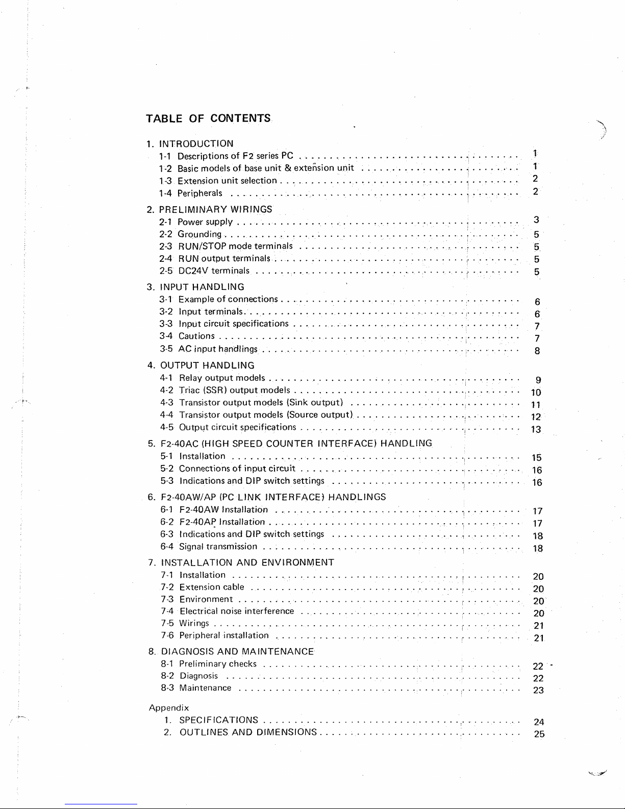
TABLE
1.
2. PRELIMINARY WIRINGS
3. INPUT HANDLING
4. OUTPUT HANDLING
5.
6. F2-.(IOAW/AP
7. LNSTALLATION AND ENVIRONMENT
8.
QF
CONTENTS
INTRODUCTION
F2
series
PC
1-1 Descriptions of
1-2 Basic models
1-3
Extension unit selection
1-4 Peripherals
2-1
Powersupply..
2-2
Grounding..
2-3
RUN/STOP mode terminals
2-4 RUN output terminals
2-5 DC24V terminals
3-1 Example
3-2 Input terminals..
3-3 Input circuit specifications
3-4
Cautions.
3-5
AC input handlings
4-1 Relay output models
4-2 Triac
4-3 Transistor output models {Sink output)
4-4 Transistor output models (Source output)
4-5 Output circuit specifications
F2-40AC
5-1
5-2
5-3 Indications and
6-1
6-2
6-3
6-4
7-1 Installation
7-2 Extension cable
7-3 Environment
7-4
7-5
7-6 Peripheral installation 21
DIAGNOSIS AND MAfNTENANCE
8-1
8-2
8-3 Maintenance
(HIGH
Installation
Connections
F2-40AW
F2-40AP Installation
Indications and DIP switch settings
Signal transmission
Electrical noise interference
Wirings..
Preliminary checks 22
Diagnosis
of
base unit & extension unit
......................................
............................................
....................................
..................................
of
connections.
............................................
.................................................
..........................................
(SSR)
output models
SPEED
COUNTER INTERFACE) HANDLfNG
.....................................
of
input circuit
DIP
switch settings
(PC
LINK INTERFACE) HANDLINGS
Instidlation
..........................................
.....................................
..................................
..................................
.....................................
..........................................
................................................
................................................
.....................................
...........................
.......................................
l........
.:.
.......
...........................
........
1
.........................................
........
.......................................
......................................
..........................................
...........................
.I.
........
.............................
-t*
.................
- * -
.....................................
*!
- * - * -
.....................................
................................
..........................................
.....................................
.....................
.........
.......
i..
.........
........
....................................
.........................................
-.;.
-;.
........
- * -
- -
....
-
1
1
2
2
3
5
5
5
5
6
6
7
7
8
9
10
11
*
12
13
15
16
16
17
17
18
18
20
20
20
20
21
-
22
23
Appendix
1.
SPEC
IF
2.
OUTLINES
ICATIONS
AND DIMENSIONS..
...........................................
...............................
24
25

I,
I
1-1
1-2
DESCRlPTlONS
OF
F2
SERtES
PC
The Mitsubishi
F2
series
of
programma bte controllers and auxiliary equipments are higher version
models
to
the F series and are ideal
for
small industrial process controt requirements and machines.
The
1/0
capacity
is
120 points max. per unit,
but
240
11'0s
can be covered by tinkage operation.
A separate ranges the
G
series and K series are available for larger and more complex application
requirements.
BASfC
MODELS
OF
BASE
UNIT
&
EXTENSION
UNfT
Nomenclatures
of
Base
&
Extension
Unit
Model
Fz
-
a
D
..
D
Ct
111
It
II
ir
Expl.
F2
-
40
M
R
-
E
S
I
It
tI
indicates the number
of
inputs/outputs 40 or
60
indicates type
of
the unit
indicates type
of
output
R:
Relay,
S:
SSR,
T:
Transistor
specifies power supply voltage rating
M:
Base
Unit or
E:
Extension Unit
N/A
.......
U&
u
L......
E
. . .
.
.
,
,
D
.
. . . . .
.
indicates type
N/A
_......
s
AI
.......
A2
.......
ss
. . .
. . .
.
. . .. . ..
100/1
IOVAC 200/220VAC
1
10/1
ZOVAC 220/240VAC
110/220VAC, 220/240VAC
24V DC
3f
input/output connections
24VDC sink input and sink output
24VDC source input and sink output
100/120VAC source input and sink output
220/240VAC source input and sink
output
24VDC source input and source output
-1-

I
F2-20H
G
P-80
FZ
F-ROM-1
F
-20P-CAB
F2 -40AC
F2 -40AW
F2-40AP
13
EXTENSION UNIT SELECTION
Program Loader
Graphic programmer
EP-ROM cassette
Remote cable
Adaptor (High speed counter input interface)
Adaptor (Wire
I
ink operation interface)
Adaptor (Optical fiber link operation interface)
I
The F2-40M
has
wo
extension ports and F2-60M has three extension ports where extension units
are connected. According to the requirements
of
t/O
numbers and other additional functions, select
the units within following applicable models;
Output:
16
Input:
4
Output:
6
).
"
12,
"
8
"
24,
*'
16
*'
24,
"
16
Output:
24
r'
36,
"
24
4
point
Analog
timer
unit
Positioning
counter module
14
PERIPHERALS
According to different function requirements far the peripheral equipments, wide range
of
periph-
erats are provided
as
follows;
1
F-2OP-E
I
Handy programmer
I
F2
-20P-E
(High function)
F-20MW
1
ROM
writer
t
?I
?I
1
GP-80ROW
I
"
"
(High function)
I
Above peripherals can
afso
be used for
the F series
PC
except F2-40AC, F2-40AW and F24OAP.
.-2-

Example
(-U
of
Type)
sink DC
input
model
(F2-40/6000,
RUN
-
F2-40/60cfU-U)
Example
1
2-1
of
source
?0/120VAC
POWER
DC
or
SUPPLY
Power supply voltage
input model
...............
(F2-40/60CICl-ES)
R
IJN
AC 110/120V
type models)
ACI 10/120V +IO%
model)
Power consumption
DC
24V
output capacity
j
(External power source) (Exctude the power
.................
..........
less
than 24VA (F2-40),
0.1A
or
AC
220/240V
or
AC 220/240V +IO%
less
(F2-40DC input model),
to
non-voltage contacts)
I1
zigz
50/60Hz
50/60Hz
than 40VA (F2-60)
0.2A
(F2-60DC input
(-4,
-ES
(-UL
model)
I
type
-3-

Example
of
sink
DC
input
model(F2-40/60C1lJ-D)
RUN
Earth
-
POWER
24VDC
/L
f-b
7
I
I
r'
I
A
m
m
Ah
TI
I
ri
7
*
Ensure that the input
[=I
terminal
is
connected to the power
@
terminal
as
illustrated above.
Example
of
source
DC
input model
(F2-40/60DCI-DS)
*
Ensure that the input
1-
terminal
is
connected to the power,
0
terminal
as
iltustrated
above.
POWER
SUPPLY
Power
supply
voltage
. . . . . . .
24VDCk8V
-4-

(1)
Connect a power supply cable of the correct rating to the base unit and extension unit (if used)
as
illustrated. Supply voltages should be
as
specified.
supply switch which can be used when the ROM cassette
(2) The power consumption of the base unit
is
less
than 25VA to F2-40 and 40VA to
however, this does not include the power consumption of any external load.
(3) The power must be switched off when the ROM
cassette
from the unit.
to
(4) The, power supply
the extension (if used) shall be connected to same
base unit.
..
-
GROUNDING
2-2
(1)
The unit must be grounded
as
illustrated. The extension unit
same line of base unit.
(2) Resistance should be
less
than
100G.
(3) Grounding must not be shared with any high power equipment such
RUN/STOP MODE TERMINALS
2-3
I
i
is
ommended to provide, power
j
F2-60
loaded on the base unit or unloaded
(if
ON/OFF
used)
also
as
a
motor system.
switch,for the
be grounded with
These terminals should
button)
as
illustrated.
The RUN mode
system).
When the STOP mode
are turned off and timers, plus the 128 of
and
64
of
the auxiliary relays,
battery support.
When the 'STOP' switch
external facilities be provided in
AC
input models,
TERMINALS
2-4
in case of
RUN
OUTPUT
(1
)
A relay contact
normal run mode, but
etc
ference,
(2)
This facifity
It
is
(3) Output load of the relay
performed through an extra relay.
be
connected to key switches or other suitable control devices
is
used when the programmabie controller
is
used (or there
state
is
on,
all
case
see
section
L-dor
is
provided between these two terminals inside. The contact
is
switched off
is
switched off in STOP mode.
is
a
power failure of
192
auxiliary relays are reset. However,
relays and some special auxiliary relays are maintained by
outputs will be
of
emergencies
'OFF'.
to
3-5.
U
if
CPU
error might be caused from electrical nqise inter-
is
running a program (controlling
more
than 20m/sec.), aflioutputs
However
it
support and back up
used to make an emergency stop circuit or warning circuit.
is
less
than 35VA. For loads over the rated limit, operation should be
ail
counters
is
recommended that
this
facility.
is
switched on
(push
a
at
2-5
DC24V
TERMINALS
In case
of
the sink input models, input devices
terminals and the
24+
imity switches or photo sensors.
In case
of
the source input models, non-voltage contact devices are powered from the
terminals and the 24V terminals have extra power capacity for
specified.
If the extension unit
unit. The
Any
COM
external power must not be supplied to
is
terminals
of
non-voltage contacts are powered from input
terminals provide DC24V power for input sensor devices such
the
input sensor devices
as
prox-
24V
as
used, connect the DC24V terminals between the base unit and extension
are
also
connected in the same manner.
these
terminafs.
-5-
!
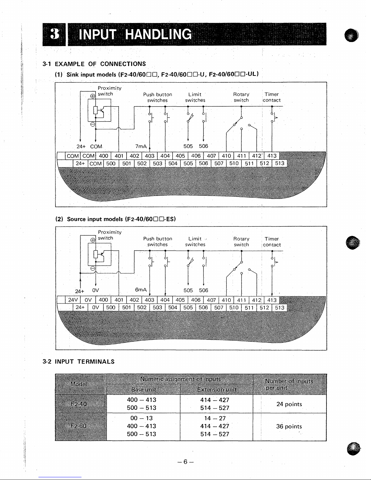
3-1
EXAMPLE
OF
CONNECTIONS
(1)
Sink input modefs (F2-40/60170, F2-40/6OOO-U, F2-40/6OUO-UL)
Proxi mi ty
K
24+
Push button Limit Rotary Timer
switches switches switch contact
(2)
Source input modefs ~FZ-~O/~OCICI-ES)
Proximity
Push button Limit
I
switches switches
6mA
505
506
24+
ov
Rotary Timer
switch contact
3-2
lNPU1
TERMINALS
-6-

3-3
INPUT CIRCUIT SPECIFICATIONS
Operation
current
__ ~
1
OC24V Input DC24V Input
(Sink input)
DC4mA Min.
OFF-'ON DC4mA Min.
I
I
Response
time
lnpuf
Input circuit
OFF-'ON Approx.
l0m.sec
Approx. 10m.sec
ON-+OFF
Approx. 5m.sec Approx. 5rnsec
DC24V
=k
4V
DC24V 5 4V
(Self-supply) (Self-supply)
Rated input voltage
I
I
I I
I
Insulation Photocoupler insulation
lnout
AC2mA Max. AC2mA Max.
Approx. 15m sec
Approx.
8m
sec
Approx.
t5m
sec
Approx.
8m
sec
I
Indication
1
LED turns ON when input
is
activated.
3-4
CAUTlONS
(I)
Connect input control devices,
e.g.
limit switches, push butto&, to the input terminations
as
specified.
(2) In case of sink input models, non-voltage contact devices are powered from the input terminals
and the 24V terminal points can be used to power external transistors such
as
proximity
switches.
The
capacity of 24V
DC
source
is
rated by
0.1
Amp
(F2-40)
and 0.2 Amp
(FZ-60)
from 24V
terminal in addition to each 7mA from
all
input terminals.
(3)
In case of source input modefs, non-voltage contact devices are powered from the 24V termi-
nals and the current rating
at
each input terminal
is
24VDC, 6mA. The control devices should
be specified accordingly.
The 24V terminal points can also be used to power externaf transistors such
as
proximity
switches.
Totaf
of
0.1
Amp (F2-40) and 0.2 Amp
(F2-60)
current by two 24V terminals can be used for
such transistors in addition to each
6mA
suppty to
all
input terminals.
If further more power
is
requested, use an externaf power source of
16
to
36V DC.
The
OV
terminals
are
used for negatives of 24V
DC
source.
(4)
If
transistor circuits, such
as
proximity switches, are connected to input terminals and have
a
parallel or series resistance, their parallel should be more than
10OKL-l
and their series resistance
less
than
1
KO2.
(5)
Three common terminals
are
connected internally and are common. However, thte base and
extension unit commons are not linked unless connected together externalfy
as
detailed in
other section.
The common terminal
is
also used for
a
negative
of
24V
DC
source.
(6)
For the sake of convenience and appearance and to avoid damage of failure, input wires should
be bound or cabled together.
It:
is
recommended
that
input wires are not longer than 20 meters for the general use, However,
the tength can be longer but depends upon the conditions of the noise environment and voltage
drop.
-7-

3-5
AC
INPUT
HANDLINGS
(F2-40/60OO-C1A1,
A2)
When
no
contacr
input
devises such
as
proximity
switches
or
photo
sensors are connected
to
input
terminals, be aware that the leakage current may activate the
input
signal
incorrectly.
Where the leakage current
is
more than
2mA,
it
may prove necessary
to
provide additional
bleeder resister
or
CR
circuit (ex.
0.5yF
+
IOOSt),
otherwise use
input
devices
with
tow
leakage
current
less
than
2mA.
Run
stop
switch switch Limit switch
1
IO/
I20V
-
(Example:
F2-40MR-UAi
1

4-1
RELAY
OUTPUT
MODELS
(FZ-40/6OO
R,
-0U)
4
4
points
corn mo
4
4
points
n
common
points
common
points
common
\-\/u-
4
points
common
4 points
common common
4 points
4
points
common
points
common common
4
points
4
Connect external load devices e.g. contactors, pilot lamps, solenoid (electromagnetic) valves, etc.,
to
output terminations of the base unit and extension unit
As
shown in the above figure, four common terminals are provided for the output terminations.
As
these commons are not linked and cover each four
types
of
block
share one type
power can
be
used as shown in the above exampte as far as the output terminals
of
power.
(if
output
used).
terminals
in
their block, different
in
t
a
-9-

0
Normal open relay contacts are connected internally
to
the output terminals
on
the base and
extension units, The ratings
of
the contacts are
2A
at
24V
DC,
110/120V AC, 220/240V
AC.
These ratings apply
for
resistive loads
(COS
(6
=
1
.O).
The durability data of output relay
is
stated in other section
(4-5).
0
Each internai contact
is
protected by a residual current circuit. When the contact is closed,
its
current leakage will normally be less than 1 .lmA
at
220V
AC
or 0.55mA at
21OV
AC.
However,
it
is possible that this might have
some
effect on external loads.
Where the external current demand
is
very low,
it
may prove necessary
to
provide additional
parallel resistance because
of
the influence
of
leakage (see section
4-5).
e
When using the controller in a direct current circuit,
it
is recommende'd
to
connect a free whee!
diode in paratlel
to
the inductive load.
@
4-2
TRIAC
(SSR)
OUTPUT
MODELES
(F2-40/60cIS,
-DU)
1'09"
1
44
0
I
4 4
1
1
4 4
2
I
44 3
r:2
I
444 f 44 5 f 4 4 6 I 447
1
54
0
1
54
t
1
54
2
I
5 43
IC,??
I
5441 5451 546 1 547
I
2
4
points
4
points
common common
4
points
common
4
points
common
4
points
4
points
4
points
4
points
4
points
4
points
common
common
common
common common common
-
10-

I
Connect external load devices e.g. contactors, pilot lamps, sotenoid (electromagnetic)
to output terminations of the base unit and extension unit (if used).
As
As these commons are not linked and cover each four output terminals in their block, different
types of power can be used
block share one type
The load limitation of the triac
collective output load should no exceed
24OV.
For inductance loads, the rated coil of magnetic contactors
12OV
be required. For lamp loads above
Each triac
residual current circuit. With the triac
2.2mA
It
4-3
TRANSfSTOR
shown in the above figure, common terminals are provided
as
of
power.
shown in the above example
(SSR)
outputs
8A
across
is
1A
for each individual output, but the total
all
16
as
outputs
sl-tould
or 100VA
at
AC
is
not possible to operate triac output card
at
AC 220/240V. If the coil toad
(SSR)
inside the
220V. However,
OUTPUT
MODELS
is
over these limits, then an externa1)relay
IOOW,
unit
will withstand moderate surge currents, and
it
is
(F2-40/60CIT,
an external relay will atso be required.
'off'
current leakage
possible that this might have some effect on external loads.
on
DC
toads.
-17)
is
SINK
for
far
as
at
AC
be within 50VA
less
than 1.2mA
OUTPUT
valves,
the output terminations.
the output terminals in
110/120V or
at
is
protqcted bv
at
AC 120V or
TYPE
AC
AC
etc.,
220/
110/
will
a
a
I
i
?
1
DC24V 0 14301 431
/4321433143414351436f437[53015311532[5331534i
2A
d
t
P
b
4
535[536[5371
DC24V
0
I
DC24VO 31 33 35 37 431 433 435 437 531 533 535 537 DC24VO
40 42 44 46 440 442 444 446 540 542 544 546
DC24VO
41
43 45 47 441 443 445 447
541
543 545 547
DC24V
@

0
Connect external load devices
e.g.
contactors, pilot lamps, solenoid (electromagnetic)
valves,
etc.,
0
The load limitation
of
the transistor outputs
is
1A
for
each individual ouiput, but the collective
output toad should not exceed
2A
per 4 points
at
DC
24V.
8
Due to surge current limitations lamp loads should be within 3W.
0
When other load are connected to a output termination in addition to lamp load, the totaf collec-
tive
output load should be
as
specified with reference to following table.
to output terminations
of
the base unit and extension unit.
i
\
2w
6W
1w
I
16W
I
I
0
24W
I
0
The external DC power supply should be
DC
24V
+15%/-30%.
0
2A
rated back-up fuses or protectors are recommended per each four outputs
'to
prevent damage
to the circuit boards
of
the PC in the event of a short circuit fault in one of the external circuits.
4-4
TRANSISTOR OUTPUT
MODELS
(F2-40/600T-ESS)
SOURCE OUTPUT
TYPE
1
130 I 32 I34 136 1 14301432143414361 15301532153415361
I
1
I
DC24VO 41 43 45 47 441 443
445
447 541 543 545 547
DC24VQ
-
12
-

Connect external load devices e.g. contactors, pilot lamps, solenoid (electromagnetic)
to output terminations of the base unit and extension unit (if used).
The
load
limitation
output load should not exceed
Due to surge current limitations lamp loads should be within
When other load are connected
tive
output load should be
of
the transistor outputs
2A
per 4 points
to
a
output termination in addition to lamp load, the total collec-
as
specified with reference to following table.
is
at
1A
DC
for
each individual output, but
24V.
3W.
2w
1w
0
The
external
2A rated back-up fuses or protectors are recommended per each four outputs to prevent damage
to the circuit boards of the
4-5
OUTPUT CIRCUIT SPECIFICATIONS
~~
Output circuit
DC
power supply
Relay Output
should
PC
in the event
6W
16W
24W
be
DC
24V
of
a
Triac Output
i
+I
5%/-30%.
short circuit fault in one
Transistor Output
(Sink output)
of
the external ,circuits.
Transistor Output
(Source output)
External power source
Rated output current
(Resistance load)
Lamp load
Rush
current
Leakage current
Min. Load
(Inductive load)
Response
time
Circuit insulation
Indications
Less
than 250VAC
I30VDC
2AIpoint
Detailed below
tOOW
1OAICycle
0.55mA111 OVAC
l.lmAl220VAC
0.2VAlllOAC
0.8VAl220VAC
Approx. 5m.sec
Approx l0m.sec
Relay
insulation
LED
(When relay
is
activated)
coil
80-240VAC
tA1point but 2A
4
points toral
per
50VA
(1
loll
1
OOVA (220/240VAC)
lOOW
1 OAICycle
1 .lmAIllOVAC
2.2mA1220VAC
0.4VAIl TOVA
1.6VAl220VAC
Less than 1m.sec
1Om.szc Max.
Photo-triac
LED (When triac is
activated)
20VAC)
+?O%
24vDc-30%
IA/point but 2A
per
4
points total
24W (24VDC)
3W (Detailed in
Section
4-3)
BAllOms
-
Less than 1m.sec
Less than 1 msec
Photo-coupler
LED (When photo-
coupler is activated)
+lo%
24VDC-30F
tA/point but 2A
4
points total
per
24W (24VDC)
3W (Detailed in
Section 4-4)
SA11
Oms
-
I
Less than Irn.sec
Less than 1m.sec
Phot ocoupler
LED (When photo-
coupler is activated)
!
-13-

The basic
unit
and extension
unit
have the output power ratings indicated in the above table. For
loads over the rated maximum limits shown, operation should be perforhed through
an
extra
relay, capable of handling the load. Loads under the minimum limits shown
will
need
an
additional
surge absorber circuit (approx.
O.1pF
+
1OOSt)
to prevent incorrect operation due
to
leakage currents
ftowing
in
the output circuits.
Less than
35VA
Less than
80VA
Less than
120VA
on
I
Back-up fuses or circuit protectors are recommended on output circuits to prevent damage to the
circuit boards of the
PC
in
the event
of
a short circuit fault
in
an
external output circuit.
Inductive
toad
of
Relay
Output
Appticabte toads to the output relays are subject to the frequency
of
operations. According to our
life test data, followings are given for
a
reference
of
the relay durability level;
UP
to
3,000,000
UP
to
1,000,000
up
to
200,000
I

--
5-1
I
NSTAL
LATI
ON
'ER
1)
Connect a connector
PC.
the
2)
Fit the hooks in
the
PC.
3)
Slide the plastic cover upward ,to remove
the cover.
4) Connect the input wires to the terminals
and adjust the
DIP
of
the F2-4OAC to
the
installation holes
switch.
of
I
-
15-

3
5-2
CONNECTIONS
OF
INPUT CIRCUIT
Example
of
proximity
switch
lt---ll---
Proximity
switch
Pulse:
2KMz
Max
(ON:
0.25ms,
OFF:
0.25ms)
5-3
INDICATIONS AND DIP-SWITCH SETTINGS
Terminals
LED
indications:
1
.......
Mode selection tM470)
2
.......
Up/down selection (M471)
3
.......
Start (M472)
4
.......
input signal
DIP switch
setthgs:
SWI
.......
Switch
ON
only when 5VDC
is
used for input device.
SW2
.......
Switch
ON
only when 12VDC
is
used for input device.
SW3
.......
Switch
ON
only when 24VDC
is
used for input device.
SW4
.......
Switch
ON
only when input filter
is
required.
-16-
"_
..........
.....
...
.....
.............
yl_
..,...
.-,--
,~-..,"
I

6-1
FZ-4OAW
(WIRE
LINK) INSTALLATION
Attach the
Connect two
sealing twist are connected
The cable length shall be less than
suppty cables
6-2
FZQOAP (OPTICAL
unit
units
to
Fz-40 A
the
PC
in
with
a twist-pair cable as illustrated (SA
W
the same manner
to
the earth terminals
10
or
other such electrical apparatus
FIBER
Optical
connectors
LINK) INSTALLATION
/
as
the F2-40AC (Section5-1).
of
the
meters (approx.
to
avoid electrical noise interference.
Optical
to
SA,
SB
PCs.
35
feet) and keep away
F2-40A
to
SB),
W
and
from
both
ends
of
high voltage
Attach the
Connect
The cable length shall be less than
The optical fiber cables and opticaf connectors are
specifications and
unit
two
to
units
the PC
with
supply
in
the same manner as the F2-40AC (Section
optical plastic fiber cables as illustrated
50
meters (approx.
shall be inquired
to
Mitsubishi agent.
160
not
feet).
included
-17-
5-1
).
(R
to
T,
T
to
R).
in
the attachment. The material

6-3
INDICATIONS
AND
DIP-SWITCH
SETTINGS
6-4
(Expt. F2-40AW)
LED indicatigns:
1
.......
Power supply
2
.......
Linkage
RUN
3
.......
Signal transmission
4
.......
Transmission error
DIP
switch settings:
SW1
.......
Switch
OFF
at any time.
SW2
.......
Switch
ON
at any time.
SW3
.......
Since
two
PC
units must be identified
for
the signal handlings mentioned
in
the next
section
64,
the
SW3
makes identifications
of
both
PCs
as follows:
ON
.......
Side A PC (Master)
OFF
.....
Side
B
PC
(Slave)
SW4
.......
Switch
ON
to
transmit
32
points
of
signals
or
switch
OFF
to
transmit
16
points
of
signals.
SIGNAL TRANSMSSION
For the linkage operations
of
two
PCs,
certain auxiliary retays are shared
with
both
PCs
and the
signal transmissions are as follows:
(I
)
32
Points Transmission
Side
B
(Slave)
PC
Side
A
(Master)
PC
I
Receiving
Side
B
PC
can activate the auxiliary relays
M100-Ml37
subjectively and Side
A
PC
receives the
data
to
share
with
the contacts
in
the program.
On
other hand auxijiary relays
M140-MI77
are
activated
by
Side
A
PC
and the data is shared
by
Side
B
PC
with
the contacts.
(Auxiliary reiay
M100-M137
cannot
be
activated
by
Side
A
PC
and
M140--177
cannot be
activated
by
Side
B
PC.)

j
I
Receiving
1
In
Side
Ref.
1)
2)
Side B (Slave)
M140-Ml57
the same manner
B
PC
and M140-157
Linkage operation
expected to
It
takes approx. 7.2m.sec
time
of
receive
signal transmission
PC
as
32
point transmission, auxiliary relays
is
activated by Side
of
32/?6
from another
I
16
points
A
PC.
points
for
is
is
also availabte. But the auxiliary relays
PC
must not be activated for the coit.
the signal transmission between the
7.2m;sec
plus
a
execution time
Side
A
(Master)
M100-Ml17
PCs.
of
the
PC.
PC
are activated by
of
which data
Maximum delay
is
I
i
I
i
i
i
I
~
!
I
-19-

7-'!
INSTALLATION
Screw
4-M4
Screw
4-M5
F2-40:
F2-60:
Screw
hole
pitch
240(9.45)
335(
I
3.19)
h-
d-3.N
eo!
2s
..
..
UU-
mm
(inch)
The base unit and extension unit can be mounted with suitable screws direct
by using the four corner holes provided.
DIN
raii mounting kit
Do
not attempt to install the equipment on the floor surface or ceiling
is
available for
F2-40
models.
rise.
Do
not fail to install the equipment
in
case
unit through
boards of the
7-2
EXTENSION CABLE
(1)
Extension cables of
of
mounting the unit on the wall surface, beware
the
ventilation opening etc. Conductive trashes may cause damage to the circuit
PC
or
operation faiiure,
0.6
meter (1.97
on
the wall surface.
feet)
length
(2) The extension cables used to connect the basic unit and
a
400,
distance
500
are marked to each extensi,on port, and the ports
rate from any other cables or wires by
(3)
l/O
assignment numbers e,g.
00,
with same npmber shall be connected between the base unit and extension unit,
Labels of
00,
400
and
500
are attached to the base unit for the usage
F-20E.
7-3
ENV!RONMENT
of
are
attached in the
an
of
30mm
to
any flat surface
to
avoid temperature
conductive Trashes falling into the
F2-40E
and
F2-60E
unit.
extension unit should be kept sepa-
(1.2
inch)
at
least.
of
F-4T,
F-1OER or
White the
F
series
PC
is
suitable for most industrial sitcztions,
hostile environments associated with extremes of damp, dust, temperature, corrosive
or mechanical impact. The unit should not be installed in
to rise to above
50°C
(122'F) and a space of some 50mm
unit for heat dissipation.
7-4
ELECTRICAL
NOISE
1NTERFERENCE
To avoid electrical noise interference from some external apparatus, the unit should not be installed
near high voltage supply cables or other such electrical apparatus. Input and output wires must be
kept separate and away from any power supply cables or high voltage cables.
it
should not be used in excessively
gases,
vibration
a
situation where <he temperature
(2
inches) shoutd be allowed around the
-
20
-
is
likely

7-5
WIRINGS
led together
(2)
It
is
recommended that input and output wires are not fonger than
general use. However the length can be longer but depends upon the conditions
environment and voltage drop.
(3)
DC
cable and
(4)
External emergency stop circuit or interlocks for dangerous contactor such
AC
cable should not be bound together.
shall be provided in addition to the
(5)
If
internal power fuse should be cut
may not recover the unit.
7-6
PERIPHERAL INSTALLATION
(1
}
The power must be switched
(2) When F2-20P-E or F-20P-E
the programme must be
nd appearance and to avoi
as
well
as
output wires.
PC
sequence.
in
a
event
off
when the
is
plugged on the
MONITOR
mode.
ROM
PC
20
meters
of
wrong voltage supply, the fuse replacement
cassette
during the
is
loaded or unloaded.
PC
power
is
ON.
(65
feet) for the
of
the noise
as
forward/reverse
The slide switch
I
i
1
of
-21
,
,
-

,
INARY
ope
CHECKS
the unit,
it
is
advisable to carry out
the following checks:
a.
That the power and ground leads are properly con-
nected.
b. That input and output leads
and not entangled.
load according to
c.
that output loads and input contacts are within the
specification
(It
is
is
input and output assignment.)
I
imits detailed earlier.
are
property connected
worthwhile numbering each
d. That program/monitor mode on the programming
panel and RUN/STOP mode on the base unit are
properly
e.
That the extension cable
f.
Programmes can be checked and monitored by using
set.
is
properly connected.
the facility available on the programming panet for
this purpose.
8-2
DIAGNOSIS
r
Power
jndi$Or
supply
RUN
indicator
Battery vot
i
CPU.
PROG. ERROR
indicator
I
tage indicator
ERROR
I
The base unit's
(1
1
Power Supply t ndication
LED
is
under apparent power, open the fuse cover and check the fuse. If the
LEDs
illumination indicates that the power
the unit may be faulty.
(2)
Run indication,
ff the run
unit
(3)
Battery
is
faulty.
LED
is
in 'run' mode then (assuming
tf the battery
ry relay
(4)
Program Error tndication
CPU
I
)
M76
is
ERROR
Programming errofs
Timer or counter without constant
a.
b. Grammatic error in a program
c,
Circuit error in a program
2)
Battery voltage drop
3}
Sum-check error, which may be caused by nois? interference or conductive debris falling
into the unit.
In this
case,
ty of conductive debris, and try to operate again
enable the following conditions to be checked:
is
'on'. If the
.
is
not illuminated when the programming panel
all
wiring connections
LED
iltuminates, replace the battery immediately. At same time, a special auxitia-
turned
LED
ON.
flickers when following errors are caused:
LED
fails to illuminate when the unit
PC
will
not recover,
is
turned to 'monitor' and the
to
be correct),
it
is
likely the unit
K
check the program, battery voltage indication, electrical noise source or posibili-
after
the power reset.
'
22
-

(5)
CPU Error Indication
CPU
ERROR
LED
is
turned
ON
in
following case:
1) CPU execution error
is
caused
by
noise interference or conductive trashes fallen
2)
ROM
cassette
is
toaded or unloaded when the PC power
is
turned
ON.
3)
Watchdog timer error
is
caused if program execution time
is
more than
0.1
second.
unit.
into the
a.
In this case, turn the
PC
power
OFF
and switch
ON
again
(power reset).
If
the
PC
operation
is
recovered, check the electrical noise source or possibility of conductive trashes.
b. If the CPU
ERROR
LED
flickers after power reset, check the pragram error in the same
manner
as
former item (Section
8-2(4)).
c. If the CPU ERROR
LED
is
still
turned
ON,
check the program execution time.
In case of failure of the input
LEDs
to illuminate, check the
ON/OFF
status in the program
with programmer, and check whether input switching device works properly. Beware following
possibilities
:
(6)
input Indications
a.
If current rating of input device
is
too large, contact error may be caused.
b. When the bleed resister for external
LED
indication
is
provided in parallel to the input
device, the
PC
input may be turned
ON
incorrectly because
of
the leakage current.
c. The
PC
may not accept
the
input signal which
is
shorten than PC execution time.
(7)
Output fndication
If outputs fail to function, beware following cases might be caused:
a.
In
case
the very low current device
is
connected to the relay output or triac output
PC
models, the output device may be activated incorrectly because of the
PC
leakage current.
b. The short circuit and large current load may cause the damage of the
PC
relay contact or
damage
of
triac and transistor device in the PC, which cause output failure.
8-3
MAINTENANCE
(1)
Periodical Check
The
PC
does not contain wasting component except a lithium battery and output relays.
The battery life
is
approx. 5 years
(1
year warranty) and relay life
is
subjected to the frequency
of operations and current
level
(see
the section of output handling).
The battery
is
replaced in the manner stated below.
The units installation should be checked to ensure that
it
has not been contaminated by dust or
other contaminations, also that
all
terminal connections are
stilt
tight.
The unit should not be installed in
a
situation where
the
temperature
is
likely
to
rise
to above
5OoC
(122°F).
(2)
Battery Renewat
a.
The program
RAM
memory and a part of software functions are backed by a non-chargeable
lithium battery, of which discharge life
is
more than five years
(1
year warranty). When the
battery voftage runs tow,
LED
indicator
on
the base unit
is
itfuminated. However, regardless
of
its
condition,
it
is
recommended that the battery be replaced every five years.
b.
To
renew the battery, remove a pannel cover
of
the base unit and renew the battery within
30
seconds, while an inside capacitor supports the memories.
-23-

f
1
!
>
I
i
i
1
I
Power-failure compensation
Ambient temperature
Storage temperature
Ambient humidity
Vi bration resistance
fa
tion resistance
In su
Insulation withstand voltage
CPU
Memory
Method
Program language
Instructions
Program capacity
Execution speed
Memory
CPU
Self-d iagnostics
Battery
DC24V+8V
:
FZ-40: 25VA, FZ-60: 40VA
:
20m.sec.
:
0-55OC (32- 13loF)
:
-15-65OC
:
85%
(no condensation)
:
10 - 55H42,0.5rnm (Max. 2G1
:
5MCl (5OOVDC)
:
1500VAC, 1 minu.
:
Stored program, Repeated arithmetic
:
Relay and logic sym bok
:
Sequenciat instructions
Step-ladder instructions
Functional instructions
:
1000 steps
:
Average 7p.sec/step
:
C-MOS RAM standard, EP-ROM option
:
p.p
8031
:
Sum-check, watch-dog timer, battery voltage,
(-D, - DS
(5-
149OF)
Type)
:
:
:
35
2:
i
-rota'
power supply voltage, etc.
:
Lithium battery
57
~~
__
~
Functional
Number
Number
of
of
output
input
Input sensor power
Timers
Counters (backed by battery)
Auxiliary relays
No
battery back-up
Backed by battery
State
JM
P/EJP
:
F2-40 (Base unit): 24 points (W/RUN, STOP inputs)
(Base
F2-60
F2-40 (Base unit): 16 points
F2-60
:
F2-40 (Base unit): 24VDC 0.25A total (All inputs turned OFF)
~2-60
:
0.1
-
-
0.01
:
1
-
999:
:
128 points (M100- M277)
:
64
points (M300 - M377)
:
40 points (M600 - M647)
:
64 points (M700 - M777)
unit): 36 points (W/RUN, STOP inputs)
(Base
unit):
(W/RUN
24
points (W/RUN contact)
contact)
(Base unit): 24VDC 0.43A total (ditto)
999
sec.
timer: 24 points
99.9
sec. timer: 8 points (3 digits)
32
points Up/down available
-
24
-
(3
digits)

OUTLINES
AND
DIMENSIONS
I
Fz-60M
BASE
UNIT
mm
(inch)
350 (13.78)
d
..
..
~
7-
I
-M3.5
screw terminals
I
F2-40M BASE
UNIT
I
110
(4.33)
(o.43)
-+I--
,
-I-,,
i,
(0.197)
Weight
2.7
kg
(5.95
Ibs}
FZ-60E
EXTENSION
UNIT
350
113.78)
110
(4.33)
335
(13.19)
,
-25-
3

J
Y992D02801
C
(ROD)
The specifications and designs
are
subject to change without notice.
--
 Loading...