

Page 1

Mitsubishi Industrial Robot
CR750-Q/CR751-Q series controller
iQ Platform Supporting
Extended Function Instruction Manual
CRnQ-700 series controller
BFP-A8787-F
Page 2

Page 3

All teaching work must be carried out by an operator who has received special
Always read the following precautions and the separate "Safety
Manual" before starting use of the robot to learn the required
measures to be taken.
Safety Precautions
CAUTION
CAUTION
WARNING
CAUTION
DANGER
CAUTION
CAUTION
CAUTION
training. (This also applies to maintenance work with the power source turned
ON.)
Enforcement of safety training
For teaching work, prepare a work plan related to the methods and procedures
of operating the robot, and to the measures to be taken when an error occurs
or when restarting. Carry out work following this plan. (This also applies to
maintenance work with the power source turned ON.)
Preparation of work plan
Prepare a device that allows operation to be stopped immediately during
teaching work. (This also applies to maintenance work with the power source
turned ON.)
Setting of emergency stop switch
During teaching work, place a sign indicating that teaching work is in progress
on the start switch, etc. (This also applies to maintenance work with the power
source turned ON.)
Indication of teaching work in progress
Provide a fence or enclosure during operation to prevent contact of the
operator and robot.
Installation of safety fence
Establish a set signaling method to the related operators for starting work, and
follow this method.
Signaling of operation start
As a principle turn the power OFF during maintenance work. Place a sign
indicating that maintenance work is in progress on the start switch, etc.
Indication of maintenance work in progress
Before starting work, inspect the robot, emergency stop switch and other
related devices, etc., and confirm that there are no errors.
Inspection before starting work
Page 4

The points of the precautions given in the separate "Safety Manual" are given below.
DANGER
CAUTION
CAUTION
CAUTION
CAUTION
CAUTION
CAUTION
WARNING
WARNING
CAUTION
WARNING
CAUTION
CAUTION
CAUTION
CAUTION
Refer to the actual "Safety Manual" for details.
When automatic operation of the robot is performed using multiple control
devices (GOT, programmable controller, push-button switch), the interlocking of
operation rights of the devices, etc. must be designed by the customer.
Use the robot within the environment given in the specifications. Failure to do
so could lead to a drop or reliability or faults. (Temperature, humidity,
atmosphere, noise environment, etc.)
Transport the robot with the designated transportation posture. Transporting
the robot in a non-designated posture could lead to personal injuries or faults
from dropping.
Always use the robot installed on a secure table. Use in an instable posture
could lead to positional deviation and vibration.
Wire the cable as far away from noise sources as possible. If placed near a noise
source, positional deviation or malfunction could occur.
Do not apply excessive force on the connector or excessively bend the cable.
Failure to observe this could lead to contact defects or wire breakage.
Make sure that the workpiece weight, including the hand, does not exceed the
rated load or tolerable torque. Exceeding these values could lead to alarms or
faults.
Securely install the hand and tool, and securely grasp the workpiece. Failure to
observe this could lead to personal injuries or damage if the object comes off or
flies off during operation.
Securely ground the robot and controller. Failure to observe this could lead to
malfunctioning by noise or to electric shock accidents.
Indicate the operation state during robot operation. Failure to indicate the state
could lead to operators approaching the robot or to incorrect operation.
When carrying out teaching work in the robot's movement range, always secure
the priority right for the robot control. Failure to observe this could lead to
personal injuries or damage if the robot is started with external commands.
Keep the jog speed as low as possible, and always watch the robot. Failure to do
so could lead to interference with the workpiece or peripheral devices.
After editing the program, always confirm the operation with step operation
before starting automatic operation. Failure to do so could lead to interference
with peripheral devices because of programming mistakes, etc.
Make sure that if the safety fence entrance door is opened during automatic
operation, the door is locked or that the robot will automatically stop. Failure to
do so could lead to personal injuries.
Never carry out modifications based on personal judgments, or use nondesignated maintenance parts.
Failure to observe this could lead to faults or failures.
Page 5

When the robot arm has to be moved by hand from an external area, do not
WARNING
CAUTION
CAUTION
DANGER
DANGER
DANGER
DANGER
DANGER
CAUTION
place hands or fingers in the openings. Failure to observe this could lead to
hands or fingers catching depending on the posture.
Do not stop the robot or apply emergency stop by turning the robot controller's
main power OFF. If the robot controller main power is turned OFF during
automatic operation, the robot accuracy could be adversely affected. Moreover,
it may interfere with the peripheral device by drop or move by inertia of the arm.
Do not turn off the main power to the robot controller while rewriting the
internal information of the robot controller such as the program or parameters.
If the main power to the robot controller is turned off while in automatic
operation or rewriting the program or parameters, the internal information of the
robot controller may be damaged.
Do not connect the Handy GOT when using the GOT direct connection function
of this product. Failure to observe this may result in property damage or bodily
injury because the Handy GOT can automatically operate the robot regardless
of whether the operation rights are enabled or not.
Do not connect the Handy GOT to a programmable controller when using an iQ
Platform compatible product with the CR7xx-Q controller. Failure to observe
this may result in property damage or bodily injury because the Handy GOT can
automatically operate the robot regardless of whether the operation rights are
enabled or not.
Do not remove the SSCNET III cable while power is supplied to the multiple
CPU system or the servo amplifier. Do not look directly at light emitted from
the tip of SSCNET III connectors or SSCNET III cables of the Motion CPU or
the servo amplifier. Eye discomfort may be felt if exposed to the light.
(Reference: SSCNET III employs a Class 1 or equivalent light source as
specified in JIS C 6802 and IEC60825-1 (domestic standards in Japan).)
Do not remove the SSCNET III cable while power is supplied to the controller.
Do not look directly at light emitted from the tip of SSCNET III connectors or
SSCNET III cables. Eye discomfort may be felt if exposed to the light.
(Reference: SSCNET III employs a Class 1 or equivalent light source as
specified in JIS C 6802 and IEC60825-1 (domestic standards in Japan).)
Attach the cap to the SSCNET III connector after disconnecting the SSCNET
III cable. If the cap is not attached, dirt or dust may adhere to the connector
pins, resulting in deterioration connector properties, and leading to malfunction.
Make sure there are no mistakes in the wiring. Connecting differently to the way
specified in the manual can result in errors, such as the emergency stop not
being released. In order to prevent errors occurring, please be sure to check
that all functions (such as the teaching box emergency stop, customer emer
gency stop, and door switch) are working properly after the wiring setup is com
pleted.
-
-
Page 6

Use the network equipments (personal computer, USB hub, LAN hub, etc)
CAUTION
confirmed by manufacturer. The thing unsuitable for the FA environment
(related with conformity, temperature or noise) exists in the equipments
connected to USB. When using network equipment, measures against the noise,
such as measures against EMI and the addition of the ferrite core, may be
necessary. Please fully confirm the operation by customer. Guarantee and
maintenance of the equipment on the market (usual office automation
equipment) cannot be performed.
Page 7

*CR751-D or CR751-Q controller
CAUTION
PE terminal
Grounding screw
Controller
ACIN connector
AC200V AC200V
Primary
Secondary
PE terminal
Grounding screw
123 123
ACIN connector
ACIN connector
Note 2)
Note 1) Crimping swage is recommended for connecting the attachment ACIN connector (soldering is also possible)
Recommendation compression tools: 234171-1(Tyco Electronics)
Note 2) The earth leakage breaker is the customer preparation. Always use the cover below.
Recommendation: For single primary power supply .........NV30FAU-2P-10A-AC100-240V-30mA, (Cover: TCS-05FA2)
For three primary power supply .......... NV30FAU-3P-10A-AC100-240V-30mA, (Cover: TCS-05FA3)
Note 3) If necessary, as shown in the figure, connects the noise filter between ACIN terminal blocks and primary power supply.
(Recommended noise filter: SUP-EL20-ER6 *OKAYA ELECTRIC INDUSTRIES)
Controller
<4> LINE/LOAD
<3> LINE/LOAD
<1> LINE/LOAD
<2> LINE/LOAD
Noise filter
Label
ACIN connector or
power cable
(Attachment)
Note 1)
For three phaseFor single phase
Three phase Single phase
Earth leak
-
age breaker
(NV)
Note 3)
* The controller is an
example.
Notes of the basic component are shown.
Please install the earth leakage breaker in the primary side supply power supply
of the controller of CR751-D or CR751-Q because of leakage protection.
1) Please prepare the following: Leakage current breaker (with the terminal cover), cable for connecting the
primary power supply (AWG #14 (2mm
2
or above).
(3.5mm
The secondary power cable (with the ACIN connector) for single phase or three phase power is supplied with
the product to match the specifications. When you build a cable suitable for your environment using the ACIN
connector and the ACIN terminal supplied, prepare a secondary power cable (AWG #14 (2mm
2) Confirm that the primary power matches the specifications.
3) Confirm that the primary power is OFF and that the earth leakage breaker power switch is OFF.
4) Connect the secondary power cable.
a) When using the supplied power cable with the ACIN connector
Refer to the figure above and connect the cable from the secondary side of the earth leakage breaker.
b) When building a power cable using the ACIN connector and the ACIN terminals supplied
Connect the ACIN terminals with the secondary power cable (prepared by customers), and insert the ACIN
terminals to the ACIN connector pins with the following numbers. Crimping caulking is recommended to
connect the ACIN terminals.
For single phase: 1 and 3
For three phase: 1, 2, and 3
Refer to the figure above and connect the cable from the secondary side of the earth leakage breaker.
5) Connect this ACIN connector to the ACIN connector on the front of the controller.
6) Connect the grounding cable to the PE terminal. (M4 screw)
7) Connect the primary power cable to the primary side terminal of the earth leakage breaker.
2
or above), cables to ground the primary power supply (AWG #12
2
) or above).
Page 8

Revision history
Date of print Specifications No. Details of revisions
2009-12-04 BFP-A8787-* • First edition created.
2012-03-05 BFP-A8787-A • CR750-Q/CR751-Q series controller were added.
2012-12-05 BFP-A8787-B • The statement about trademark registration was added.
2014-08-06 BFP-A8787-C • The cover and corporate logo mark of this manual was changed.
• The statement about trademark registration was modified.
2014-12-16 BFP-A8787-D • Correction of errors in a timing chart was corrected.
2015-03-10 BFP-A8787-E • The new function of software version R3p was added.
2017-05-10 BFP-A8787-F • Contact information of the authorized representative was updated.
• Correction of errors in “(3) Hand control image” was corrected.
• The corporate logo mark of illustrations in this manual was changed.
Long-precision integer number and single-precision real number can be used
for reading/writing of numeric value variables.
Page 9

*Introduction
• No part of this manual may be reproduced by any means or in any form, without prior consent
from Mitsubishi.
• The contents of this manual are subject to change without notice.
• The specifications values are based on Mitsubishi standard testing methods.
• The information contained in this document has been written to be accurate as much as possi-
ble. Please interpret that items not described in this document "cannot be performed." or "alarm
may occur".
Please contact your nearest dealer if you find any doubtful, wrong or skipped point.
•This specifications is original.
• Microsoft, Windows, Windows XP, Windows Vista, Windows 7, Windows 8, Windows 8.1 are
either registered trademarks or trademarks of Microsoft Corporation in the United States and/or
other countries.
• Windows®XP, Windows Vista®, Windows® 7, Windows® 8, Windows® 8.1 are either product
names of Microsoft Corporation in the United States.
• Ethernet is registered trademarks or trademarks of Xerox Corporation in the United States.
• All other company names and production names in this document are the trademarks or regis-
tered trademarks of their respective owners.
Copyright(C) 2009-2017 MITSUBISHI ELECTRIC CORPORATION
Thank you for buying the industrial robot MELFA manufactured by Mitsubishi Electric.
This document provides the instructions for iQ Platform supporting extended functions. Our
extended functions allows the sequencer easily to monitor the robot through shared memory
between sequencer and robot, set up data, and operate the robot without a program (sequencer
direct performance). This document provides the detailed description of data configuration of shared
memory, monitoring, and operating procedures.
Please carefully read and fully understand this document before making use of the extended functions.
Target controller of this document
This document supports the robot controller below:
• CR750-Q/CR751-Q series controller: ... Ver. R3 or later
• CRnQ-700 series controller: ................. Ver. N8 or later
Robot language MELFA BASIC V or later
Page 10

Contents
Page
1 Overview ......................................................................................................................................... 1-1
1.1 Shared Memory Extended Function List ................................................................................... 1-1
1.2 Features .................................................................................................................................... 1-2
1.3 Shared Memory Configuration .................................................................................................. 1-4
1.3.1 Memory Configuration for Valid/Invalid Extended Function ................................................ 1-4
1.3.2 Memory Map of Extended Function Area ........................................................................... 1-5
2 Preparation for Using Extended Function ....................................................................................... 2-6
2.1 Operation flow ........................................................................................................................... 2-6
2.1.1 Set up Sequencer's Multiple CPUs ..................................................................................... 2-7
2.1.2 Set up Robot's Multiple CPUs ............................................................................................. 2-8
2.1.3 Set up Parameter for Selecting Shared Memory Extended Function ................................. 2-9
2.1.4 Check Robot Language Setting ........................................................................................ 2-10
2.1.5 Allocation Example of Shared Memory ............................................................................. 2-11
(1) Multiple CPU Configuration with One Sequencer plus One Robot ................................ 2-11
(2) Multiple CPU Configuration with One Sequencer plus Three Robots ............................ 2-13
3 Monitor Robot Information ............................................................................................................ 3-17
3.1 Operation Flow ........................................................................................................................ 3-18
3.1.1 Select Monitoring Items .................................................................................................... 3-19
3.1.2 Select Target Mecha ......................................................................................................... 3-19
3.1.3 Timing Chart ..................................................................................................................... 3-20
3.1.4 Sample Ladder ................................................................................................................. 3-21
3.2 Monitoring Item ....................................................................................................................... 3-23
3.2.1 Monitor Operation Control Setting Values ........................................................................ 3-23
3.2.2 Monitor Activities ............................................................................................................... 3-25
3.2.3 Monitor Current and Aimed Positions ............................................................................... 3-26
3.2.4 Monitor Position and Joint Information ............................................................................. 3-28
(1) Select Position and Joint Data ....................................................................................... 3-28
(2) Position and Joint Data .................................................................................................. 3-30
3.2.5 Monitor Maintenance Information ..................................................................................... 3-33
4 Reads/Writes Robot's Variables ................................................................................................... 4-34
4.1 Function Description ............................................................................................................... 4-34
4.2 Operation Flow ........................................................................................................................ 4-34
4.3 How to Operate Variables ....................................................................................................... 4-35
4.3.1 Data List ............................................................................................................................ 4-35
(1) Sequencer output data ................................................................................................... 4-35
(2) Robot output data ........................................................................................................... 4-36
(3) Completion status ........................................................................................................... 4-37
(4) Data description ............................................................................................................. 4-37
4.3.2 Timing Chart ..................................................................................................................... 4-39
4.3.3 Sample Ladder ................................................................................................................. 4-40
5 Read Current Line of Robot Program ........................................................................................... 5-42
5.1 Function Description ............................................................................................................... 5-42
5.2 Operation flow ......................................................................................................................... 5-42
5.3 How to Operate Program ........................................................................................................ 5-43
5.3.1 Data List ............................................................................................................................ 5-43
5.3.2 Timing Chart ..................................................................................................................... 5-47
5.3.3 Sample Ladder ................................................................................................................. 5-48
6 Set up Robot's Maintenance ..................................................................................................
6.1 Function Description ............................................................................................................... 6-50
6.2 Operation flow ......................................................................................................................... 6-50
6.3 How to Operate Maintenance ................................................................................................. 6-51
....... 6-50
i
Page 11

Contents
Page
6.3.1 Data List ............................................................................................................................ 6-51
6.3.2 Timing Chart ..................................................................................................................... 6-53
6.3.3 Sample Ladder ................................................................................................................. 6-54
7 Read Robot Information ................................................................................................................ 7-56
7.1 Function Description ............................................................................................................... 7-56
7.2 Operation flow ......................................................................................................................... 7-56
7.3 How to Operate Robot Information ......................................................................................... 7-57
7.3.1 Data List ............................................................................................................................ 7-57
7.3.2 Timing Chart ..................................................................................................................... 7-60
7.3.3 Sample Ladder ................................................................................................................. 7-61
8 Perform Sequencer Direct ............................................................................................................ 8-63
8.1 Sequencer Direct Performance Function ................................................................................ 8-63
8.2 Operation flow ......................................................................................................................... 8-64
8.2.1 Parameter Setting ............................................................................................................. 8-65
8.2.2 Teaching ........................................................................................................................... 8-66
(1) Position Data .................................................................................................................. 8-66
(2) Position Teaching in Position Box (R32TB) ................................................................... 8-67
8.2.3 Prepare to Perform Sequencer Direct .............................................................................. 8-71
8.3 How to Operate Sequencer Direct .......................................................................................... 8-72
8.3.1 Operation Command ........................................................................................................ 8-72
(1) Sequencer output ................................................................................................................................................... 8-72
(2) Robot output .............................................................................................................................................................. 8-74
(3) Data description ............................................................................................................. 8-74
8.3.2 Timing Chart for Performing Operation Command ........................................................... 8-81
(1) Perform Operation (Normal Operation) .......................................................................... 8-81
(2) Operation Command Is Impracticable: ........................................................................... 8-82
(3) Suspend/Resume Operation .......................................................................................... 8-83
(4) Support on Occurrence of Error ..................................................................................... 8-84
(5) Suspension when Robot's External Operation Authority Gets Invalid ............................ 8-85
(6) Cancel Based on Command Request OFF Signal ......................................................... 8-86
8.3.3 Sample Ladder for Performing Operation Command ....................................................... 8-87
8.3.4 Control Robot Hand .......................................................................................................... 8-89
(2) Mapping hand signal with parameter HANDTYPE ......................................................... 8-90
(3) Hand control image ........................................................................................................ 8-91
8.3.5 Timing Chart for Robot Hand Control ............................................................................... 8-93
8.3.6 Sample Ladder for Robot Hand Control ........................................................................... 8-98
8.4 Samples ................................................................................................................................ 8-100
8.4.1 Robot Program ............................................................................................................... 8-100
8.4.2 Sample Ladder Program ................................................................................................. 8-101
8.4.3 Sample Operation Setting in GOT Screen ...................................................................... 8-109
8.5 Precautions for Sequencer Direct Performance ................................................................... 8-113
8.5.1 Requirements ................................................................................................................. 8-113
8.5.2 Running together with Program ...................................................................................... 8-113
8.5.3 Prohibit Program Startup with always Running Program ................................................ 8-113
8.5.4 Robot Language Setting ................................................................................................. 8-113
8.5.5 Operation Panel Display ................................................................................................. 8-114
9 Shared Memory Extended Function Relevant Parameter .......................................................... 9-115
9.1 Parameter of Selecting Shared Memory Extended Function ................................................ 9-115
9.2 Function Definition Parameter .............................................................................................. 9-117
10 Extended Function Relevant Error List ................................................................................... 10-118
ii
Page 12

1Overview
Note)
Note) The figure is the DU-700 series drive unit. The DU750-Q/DU751-Q series drive unit is also the same.
Monitor information
Operate robot
Instruct robot operation
Instruct robot operation
Sequence program
Shared
memory
1 Overview
These specifications describe the functions (sequencer direct performances) which extend the shared
memory in CR750-Q/CR751-Q series and CRnQ-700 series robot controller, exchange various robot information between sequencer and robot through the extended shared memory, and operate the robot without a
robot program.
Note: These shared memory extended functions only support MELFA-BASIC V or later. They do not support
MELFA-BASIC IV.
(For more information, refer to Page 10, "2.1.4 Check Robot Language Setting")
Sequencer direct performance does not support mecha 2 and 3 for multiple mecha. It supports additional axis.
1.1 Shared Memory Extended Function List
These shared memory extended functions are largely classified into monitoring and operation functions.
Monitoring function periodically updates and outputs the data in shared memory on the robot. Operation
function outputs a request from the sequencer to the robot as needed and exchanges the data. Shared
memory extended functions also provide a direct performance function to directly operate the robot.
No Item Description
1 Monitor-
ing function
2 Monitor activities Monitors the robot's activities (current
3 Monitor current and
4 Monitor general position
Monitor operation control setting values
aimed positions
and joint information
Monitors the setting values relating to
operation control command and operation control.
speed, arrival factor to the aimed position, etc.)
Monitors current and aimed positions of
robot.
Monitors various position type data (orientation at collision, etc.) and joint type
data (current value, load factor, etc.)
5 Monitor maintenance
information
Monitors the maintenance information
(battery and grease remaining times).
I/F btwn
Robots
Motoring output
(Robot side periodically updates
the data in
shared memory)
Update Cycle
7.1msec
7.1msec
7.1msec
It may differ according to each item.
Refer to Page 28,
"3.2.4 Monitor Position and Joint Information".
Depending on the
parameter MFINTVL
1-1Shared Memory Extended Function List
Page 13

1Overview
No Item Description
6 Operation
function
7 Read program's current
8 Set up maintenance Resets the servomotor information.
9 Read error information Reads detailed error information (pro-
10 Read product information Reads the robot's product information
11 Perform sequencer direct Operates the robot from the sequencer
Read/write variables Reads/ writes variables used in the
robot's program.
line
Reads currently performing line of the
robot program on a per line basis (up to
128 characters).
gram name, occurred line, etc.)
(model name, version, and serial number).
through shared memory
I/F btwn
Robots
Request reply
method
(The robot side
answers by the
output request of
the sequencer,
and delivers the
data on the
shared memory)
Update Cycle
Responds within 1s
(It may vary according to the load status
of robot control)
1.2 Features
(1) Fulfilling functions to monitor and operate robot from GOT. Advances T/B and PC-less solution.
→ Various functions can be performed by reading/ writing the data in shared memory from GOT.
● Allows you to check activities, position information, and setting values of operation control command and
thereby analyze the operation in case of debugging or problem. (Monitoring current and aimed positions,
activities, and operation control setting values)
● Allows you to read and write the contents of program and variables and thereby change the robot's oper-
ation in case of debugging or problem.
● Allows you to check and set up maintenance status.
● Allows you to check error's detailed content. (Reading error information)
● Allows you to display and check various information in the robot (product, servo information, etc.)
(2) Controls peripheral devices and system according to the robot activities with the sequencer
The sequencer allows you to monitor the data in shared memory and responsively control the peripheral
device connected to the sequencer according to the monitored value.
● Allows you to control the peripheral devices by monitoring the robot's activities (current speed, arrival fac-
tor to the aimed position, etc.)
● Allows you to generate an alarm to the system and report to the upper side by monitoring the mainte-
nance and servomotor information (load factor, etc.)
(3) Analyzes the data and performs the quality control by logging the robot information through sequencer
Allows you to analyze the system data and perform the products' quality control by sending the logged robot
information in shared memory to the sequencer and upper device connected to the sequencer.
● Allows you to control the system's operating situation by logging error information.
● Allows you to perform the quality control of product assembly by logging servo monitor information (cur-
rent value, etc.)
Features 1-2
Page 14

1Overview
(4) Allows to operate the robot without learning robot language (sequencer direct performance)
● Allows to operate the robot without knowing robot language.
Allows you to operate the robot by writing predetermined setting value into the specified address in
shared memory. Therefore, this function can be fulfilled regardless of sequencer language (ladder, ST
language, SFC, etc.)
● Allows you to select either joint or linear interpolation. Also, allows you to adequately specify the robot
operations such as override, acceleration and deceleration, tool setting.
Command Action
Operation control
Definition command
Hand command
Mov Move for joint interpolation
Mvs Move for linear interpolation
Ovrd Specify the overall speed
Spd Specify the linear interpolation speed
Accel Specify the acceleration and deceleration speed
Tool Specify the tool data
Hopen/Hclose
Open/close a hand
● Allows you to operate the robot with a sense, which is familiar to the sequencer programmer, to move a
positioning unit.
● Allows you to control the system operations only with sequencer.
Makes the program management easy so that a sequencer programmer can support for the change of
system specification and the problem.
● Allows you to control the system settings only with the sequencer in the GOT screen.
A sequencer programmer can support for the change of system specification and the problem so that the
program management gets so easy.
1-3Features
Page 15

1Overview
Robot input area
(Sequencer output area)
0
511
0
511
0
511
512
1023
User area
User area
0
511
User area
User area
Extended
function area
・
・
・
Robot output area
(Sequencer input area)
0.5K
words
extended
Total 1K
word used
512
1023
Extended
function area
0.5K
words
extended
Total 1K
words used
Sequencer shared memory address (per word)
* Above notation is an offset address from the beginning
・
・
・
Sequencer shared memory address (per word)
* Above notation is an offset address from the beginning
Robot input area
(Sequencer output area)
Robot output area
(Sequencer input area)
Sequencer shared memory address (per word)
* Above notation is an offset address from the beginning.
Sequencer shared memory address (per word)
* Above notation is an offset address from the beginning.
1.3 Shared Memory Configuration
Here, describes the shared memory configuration among multiple CPUs.
1.3.1 Memory Configuration for Valid/Invalid Extended Function
To use the shared memory extended functions, enable the shared memory extended functions with the
parameter "IQMEM".
After enabling the shared memory extended functions, the shared memory is used by extending the robot I/
O area by 0.5 K word.
Extended Function Invalid
Extended Function Valid
Note) Only the user area can be referred to by robot program, signal monitor, and dedicated I/O signal allo-
cation. They cannot refer to the extended function area.
Shared Memory Configuration 1-4
Page 16

1Overview
1.3.2 Memory Map of Extended Function Area
The table below lists the memory map of extended function area in the shared memory among multiple
CPUs.
* As the sequencer address may differ according to each CPU device, the sequencer address is described
in the offset address from start address.
* When not otherwise specified, the values are stored in binary format.
(1) Robot input (sequencer output) area (2) Robot output (sequencer input) area
Shared
Memory Addr
Sequencer
Description
Addr
512 Common setting area of extended function 512 Common setting area of extended function
Sequencer direct performance area Sequencer direct performance area
600 600
Shared
Memory Addr
Sequencer
Addr
Description
Common area of operation function
Read/write variables
Reading area of program's current line
Reset area of servo monitor information
Reading area of information
700 Common area of operation function 700
Reading/ writing/ teaching area of variables
Common area of monitoring function
Reading area of program's current line Monitoring area of operation control setting
values
800 800
Monitoring area of activities
Reset area of servo monitor information
Reading area of error and product information
Common area of monitoring function
Monitoring area of general position and joint
information
(Reserved: Future extended area)
900 900 Monitoring area of general position and joint
Monitoring area of current and aimed posi-
tions
information
1000 1000
1023 1023
1024 1024
1-5Shared Memory Configuration
Monitoring area of maintenance information
(Reserved)
Page 17

2 Preparation for Using Extended Function
…
…
…
● Sets up sequencer's parameter (multiple CPU setting).
For robot CPU, allocate 1K word of free user area in high-speed
communication area of multiple CPUs to robot's I/O area.
(Refer to Page 7, "2.1.1 Set up Sequencer's Multiple CPUs")
● Sets up multiple CPUs' parameters.
(Refer to Page 8, "2.1.2 Set up Robot's Multiple CPUs")
● Sets up parameter IQMEM.
1) To enable the extended function, set bit 0 to one.
2) To enable the sequencer direct performance, set bit 1 to one.
(Refer to Page 9, "2.1.3 Set up Parameter for Selecting Shared
Memory Extended Function")
● Set robot language to "MELFA BASIC V."
(Refer to Page 10, "2.1.4 Check Robot Language Setting")
"3Monitor Robot Information"
"4Reads/Writes Robot's Variables"
"5Read Current Line of Robot Program"
"6Set up Robot's Maintenance"
"7Read Robot Information"
"8Perform Sequencer Direct"
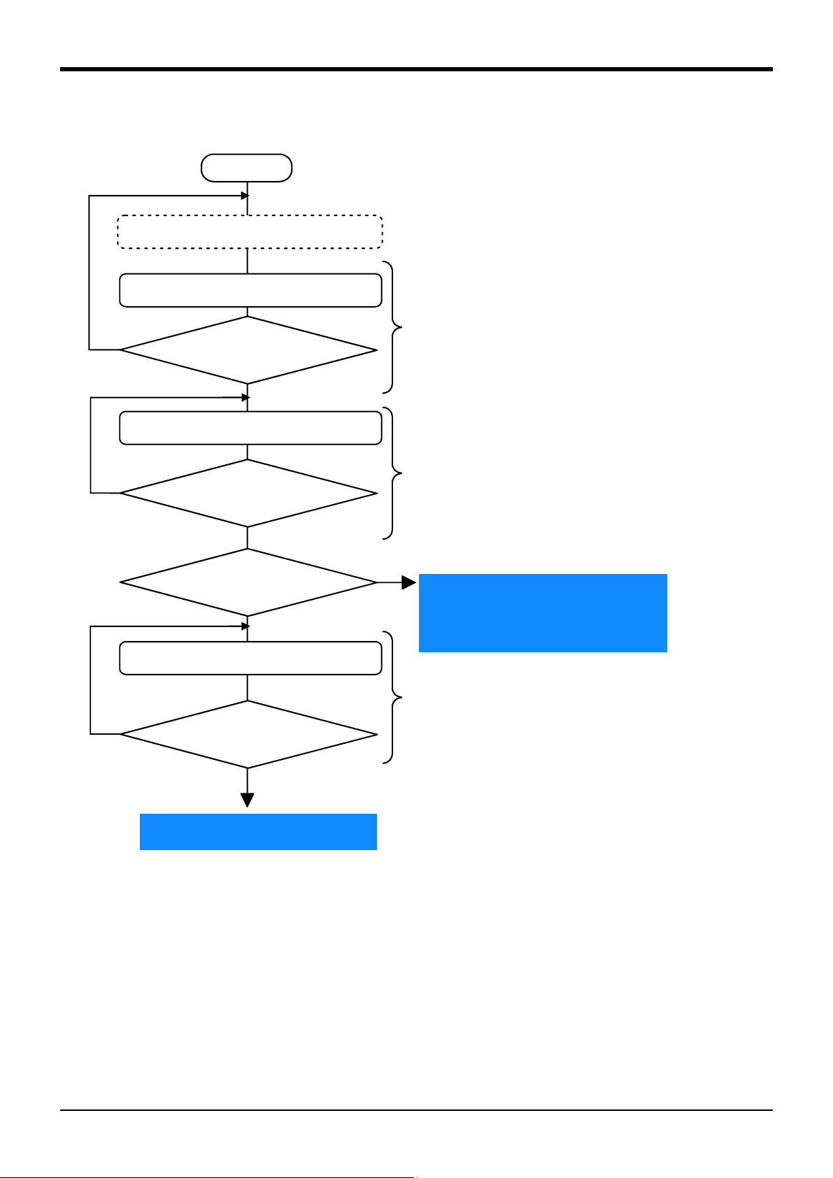
Set up sequencer's multiple CPUs
Start
Reset sequencer
Reset sequencer
Did the sequencer
successfully restart?
Carry out the functions described in
chapters 3 to 8
● Carry out the reset operation of sequencer or reset the sequencer
by turning ON the power.
2.1 Operation flow
2Preparation for Using Extended Function
Operation flow 2-6
Page 18

2Preparation for Using Extended Function
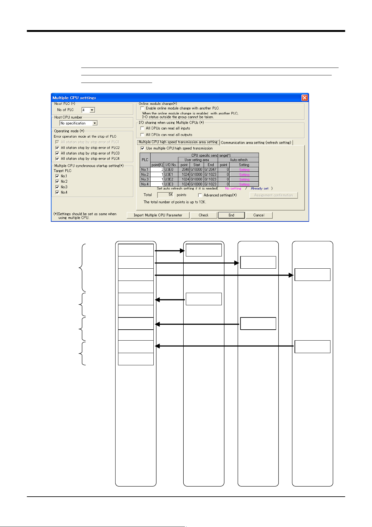
2.1.1 Set up Sequencer's Multiple CPUs
Here, sets up the multiple CPU setting as a sequencer's PC parameter. Also refer to the description of
sequencer link I/O functions described in Supplement volume "Instruction Manual, Detailed Description of
Functions and Operations."
GX-Developer multiple CPU setting screen (three robots. The shared memory extended functions are valid
in all robots)
Setting Item Description Setting Value
CPU quantity Set up the quantity of CPU units used in multiple CPU
system.
Synchronous startup
among multiple CPUs
High-speed communication area setting among
multiple CPUs
Automatic refresh setting Set up this when the device data is automatically
Set up this to synchronize the startup times of CPU
units in multiple CPU system.
* Because the robot CPU takes a dozen second for
startup, select the synchronize startup
Set up this when the data is transferred by using the
high-speed communication area
CPUs.
The necessary area for robot is as follows:
Shared memory extended functions are valid:
Robot input area: 1.0K
Robot output area: 1.0K
Shared memory extended functions are invalid:
Robot input area: 0.5K
Robot output area: 0.5K
refreshed by using the high-speed communication area
among multiple CPUs.
* Robot CPU is not supported. Always set this to zero.
Note1)
among multiple
Note1) For information about multiple CPUs and high-speed communication area among multiple CPUs, refer to the QCPU
manual (QCPU User Manual, Multiple CPU System).
Note2) Because the area is set up in 1K unit, allocate 1K even in case of 0.5K.
2 - 4
Required for check
<Shared memory extended functions are valid:>
Device #1: Sum of the size (1K) of the data to be
sent to the robot and the size of the data to be
sent to other devices
Robot device: Set 1K for it
Other devices: Set its own transmission size
<Shared memory extended functions are invalid:>
Device #1: Sum of the size (0.5K) of the data to be
sent to the robot and the size of the data to be
sent to other devices
Robot device: Set 1K for it
Other devices: Set its own transmission size
Note 2: Because the area is set up in 1K unit, allocate 1K even in case of 0.5K.
Robot device: Set zero point for it
Other devices: To use automatic refresh function,
set its score and target device
Note2)
2-7Operation flow
Page 19
2Preparation for Using Extended Function
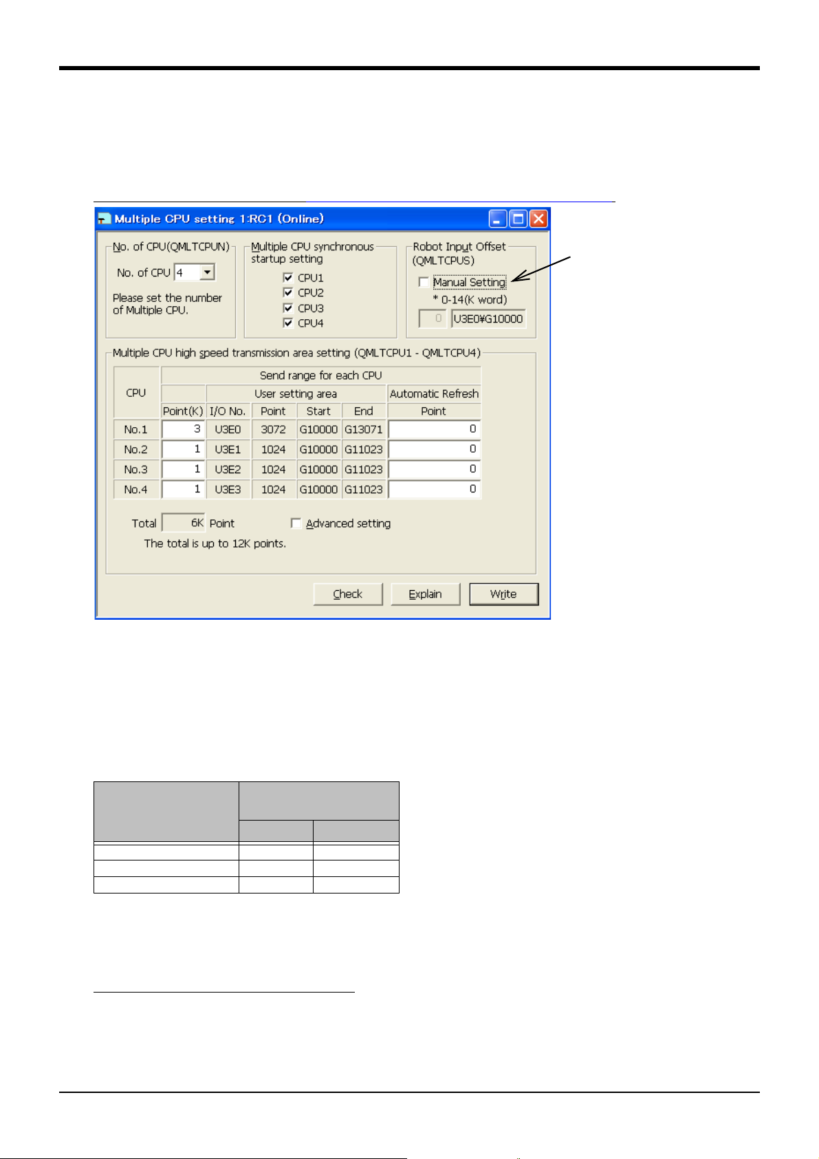
RT-ToolBox2 multiple CPU setting screen (three robots. Shared memory extended functions are valid in
all robots)
The multiple CPU input
offset parameter
"QMLTCPUS" can also
be set.
About input offset parameter (QMLTCPUS)
Sets up the offset of robot's input signals in multiple CPUs in 1K word unit.
For example, when QMLTCPUS is set to one, the start address of robot's input area is an address
(U3E0\G11024) offset by 1K word from the start address of transmission area of device #1 (sequencer).
When QMLTCPUS is set to -1 (initial value), the start address of robot's input area is as listed in the table
above.
2.1.2 Set up Robot's Multiple CPUs
Here, sets up the multiple CPUs as a robot's parameter. In the description below, parameter setting screen
of RT ToolBox 2 illustrates this setting. This can also be set up by specifying the parameter name in the
teaching box's parameter setting screen.
Set the same value as specified in
Page 7, "2.1.1 Set up Sequencer's Multiple CPUs".
[Start address of robot input offset]
The Table 2-1 lists the start addresses of robot input area in the robot's initial setting (multiple CPU input off-
set parameter "QMLTCPUS" is set to "-1") (The start address changes according to whether the shared
memory extended functions are enabled or not).
Table 2-1:Start address of robot input area when the multiple CPU input offset parameter is initial value
Shared Memory Extended
Device No
Device #2 (robot 1) 0K 0K
Device #3 (robot 2) 0.5K 1.0K
Device #4 (robot 3) 1.0K 2.0K
Functions
Invalid Valid
The start address of robot's input area may differ, when the valid/invalid setting for shared memory extended
function may differ in other devices or when a unit other than robot is installed. In these cases, set up the
multiple CPU input offset parameter (QMLTCPUS).
For setting example, refer to Page 11, "2.1.5 Allocation Example of Shared Memory".
Operation flow 2-8
Page 20

2Preparation for Using Extended Function
Set both bits 0, 1 of
parameter IQMEM to 1
External program
variable
External program
variable for
sequencer direct
performance
(For instructing
robot location)
Sequencer direct performance is
valid
Sequencer direct performance is
invalid
:
Extend external
program variable
Set either bit 0, 1 of
parameter IQMEM to 0
Extend and delete
external program
variable
External program
variable
System state
variable
System state
variable
Set both bits 0, 1 of
parameter IQMEM to 1
Set either bit 0, 1 of
parameter IQMEM to 0
+
System state
variable for
sequencer direct
performance
Extend system state
variable
Extend and delete
system state
variable
Robot controller's internal memory
+
CAUTION
2.1.3 Set up Parameter for Selecting Shared Memory Extended Function
The parameter "IQMEM" for selecting the shared memory extended function is 16bit data. Set the bit 0 to
one to use the extended functions (monitoring, operation functions). Set the bit 1 to one to use the
sequencer direct performance function. Both bits can be set to one.
For information on how to set up a parameter, refer to Supplement volume "Instruction Manual, Detailed
Description of Functions and Operations."
Array Qty
Character
Qty
ger
Description Factory Default
Set validity (1)/ invalidity (0) for the function.
Sets each bit by allocating a function to each bit.
0000000000000000 bit2-15: Not used
|+- bit0: Use the shared memory
extended function
+-- bit1: Sequencer direct
performance function
0000000000000000
Parameter
Select shared
memory extended
function
Parameter
Name
IQMEM 1 digit inte-
To use the shared memory extended functions and sequencer direct performance functions, set each bit as
follows:
Bit 1 Bit 0
Use the shared memory extended function 0 1
Use the sequencer direct performance function 1 1
When using the sequencer direct performance function, robot's internal memory is extended as follows:
:
2-9Operation flow
When the sequencer direct performance function is valid, external program variable
and system state variable areas are extended in the robot controller (extended variables). When the function gets invalid, the extended variable area is cleared. Consequently, after the sequencer direct performance function was enabled once, the
robot location was taught, and the data was set, when the parameter is turned back,
be aware that the previous teaching and setting data will disappear.
Page 21

2Preparation for Using Extended Function
CAUTION
2.1.4 Check Robot Language Setting
The shared memory extended functions can be carried out only when the robot language is set to MELFABASIC V.
Check the value of robot language setting parameter "RLNG".
To use the shared memory extended function, set the parameter "RLNG" to 2.
For information on how to set up a parameter, refer to Supplement volume "Instruction Manual, Detailed
Description of Functions and Operations."
Parameter
Robot language RLNG 1 digit inte-
Parameter
Name
Array Qty
Character
Qty
ger
Description Factory Default
Select the robot language to be used:
2: MELFA-BASIC V
1: MELFA-BASIC IV
2
The robot controller's factory default is MELFA-BASIC V. But, when you have selected MELFA-BASIC IV, an
error "L3994" or "L3996" occurs on controller startup.
When the robot language setting is changed from MELFA-BASIC V to MELFABASIC IV, the extended variable area is cleared. Consequently, be aware that the
teaching and setting data for shared memory extended function/ sequencer direct
performance function will disappear.
Operation flow 2-10
Page 22
2Preparation for Using Extended Function
Transmission
area of Device #1
(for Device #2)
(sequencer)
Transmission
area of Device
#1, 3K word
(1K x 3)
Transmission
area of Device
#2, 1K word
Extended Function: Valid
Robot input
Robot output
Transmission
area of Device #2
U3E0\G10000
U3E1\G10000
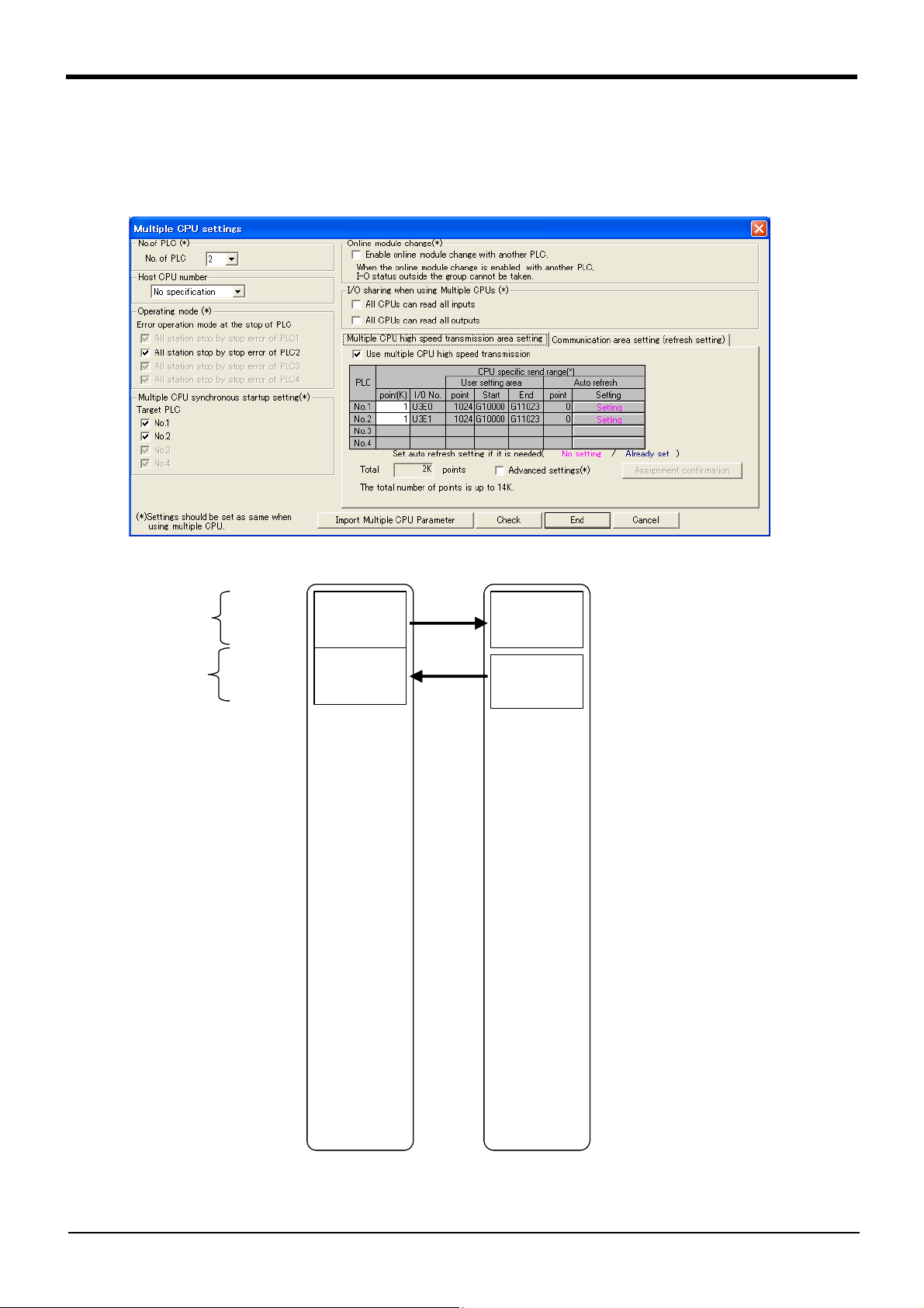
2.1.5 Allocation Example of Shared Memory
(1) Multiple CPU Configuration with One Sequencer plus One Robot
1) Case 1: Robot: Extended function is enabled, input offset parameter is initial value
The robot uses each 1K word for I/O.
Device #1
Device #2 (robot 1)
2-11Operation flow
Page 23
2Preparation for Using Extended Function
Transmission
area of Device #1
Device #1
(sequencer)
Transmission
area of Device
#1, 2K word
(0.5K x 4)
(Empty)
Transmission
area of Device
#2, 1K word
(0.5K x 2)
Transmission
area of Device #2
(Empty)
Robot input
Robot output
Device #2 (robot 1)
Extended Function: Invalid
U3E0¥G10000
U3E1¥G10000
U3E0¥G10512
U3E1¥G10512
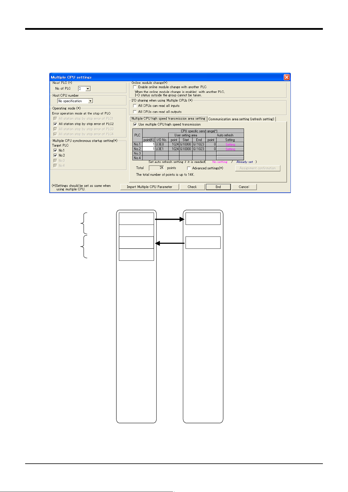
2) Case 2: Robot: Extended function is disabled, input offset parameter is initial value
The robot uses each 0.5K word for I/O.
As the transmission score is set yet in 1K word unit, the transmission score setting is as follows:
Operation flow 2-12
Page 24
2Preparation for Using Extended Function
Transmission
area of Device #1
(for Device #2)
Device #1
(sequencer)
Transmission
area of Device
#1, 3K word
(1K x 3)
Transmission
area of Device
#2, 1K word
Device #2 (robot 1)
Extended Function:
Vali d
Device #3 (robot 2)
Extended Function:
Val id
Device #4 (robot 3)
Extended Function:
Vali d
Transmission
area of Device #1
(for Device #3)
Transmission
area of Device #1
(for Device #4)
Transmission
area of Device
#3, 1K word
Transmission
area of Device
#4, 1K word
Robot input
Robot output
Robot input
Robot output
Robot input
Robot output
Transmission
area of Device #3
Transmission
area of Device #4
Transmission
area of Device #2
U3E0\G10000
U3E0\G11024
U3E0\G12048
U3E1\G10000
U3E2\G10000
U3E3\G10000
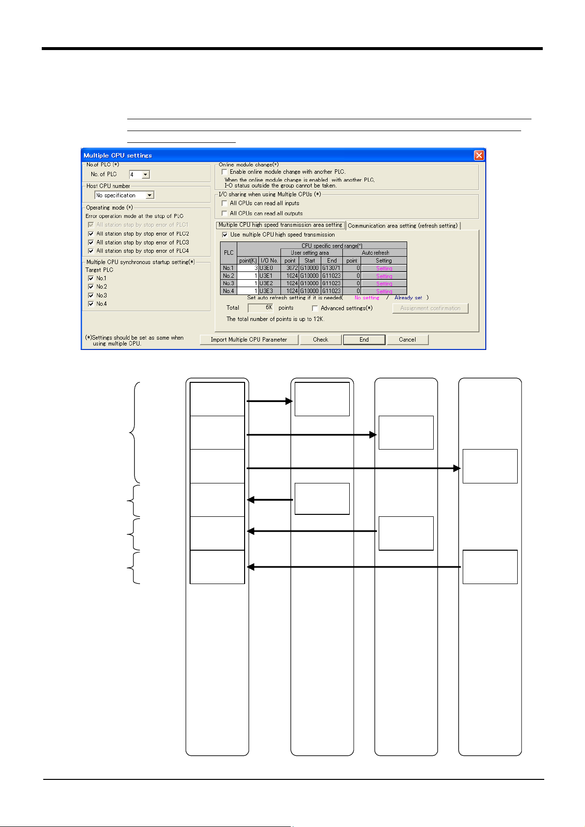
(2) Multiple CPU Configuration with One Sequencer plus Three Robots
1) Case 1: All robots: Extended function is enabled, input offset parameter is initial value
All robots use each 1K word for I/O.
The beginning of robot 2 input area starts at 1.0K offset from the beginning of shared memory
address, and the beginning of robot 3 input area starts at 2.0K offset from the beginning of
shared memory address.
2-13Operation flow
Page 25
2Preparation for Using Extended Function
Transmission area of Device #1
(for Device #2)
Device #1
(sequencer)
Transmission area of Device #1
(for Device #3)
Transmission area of Device #1
(for Device #4)
Transmission
area of Device
#1, 2K word
(0.5K x 4)
(Empty)
Transmission
area of Device
#2, 1K word
(0.5K x 2)
Transmission area
of Device #2
(Empty)
Transmission area
of Device #3
(Empty)
Transmission area
of Device #4
(Empty)
Transmission
area of Device
#3, 1K word
(0.5K x 2)
Transmission
area of Device
#4, 1K word
(0.5K x 2)
Robot input
Robot output
Robot input
Robot output
Robot input
Robot output
Device #2 (robot 1)
Extended Function:
Invalid
Device #3 (robot 2)
Extended Function:
Invalid
Device #4 (robot 3)
Extended Function:
Invalid
U3E0\G10000
U3E0\G10512
U3E0\G11024
U3E1\G10000
U3E2\G10000
U3E3\G10000
2) Case 2: All robots: Extended function is disabled, input offset parameter is initial value
All robots use each 0.5K word for I/O.
The beginning of robot 2 input area starts at 0.5K offset from the beginning of shared memory
address, and the beginning of robot 3 input area starts at 1.0K offset from the beginning of
shared memory address.
The setting is in 1K word unit as follows:
Operation flow 2-14
Page 26

2Preparation for Using Extended Function
Device #1
(sequencer)
Transmission
area of Device
#1, 2K word
(0.5K x 2, 1K x1)
Transmission
area of Device
#2, 1K word
Device #2 (robot 1)
Extended
Function: Invalid
Device #3 (robot 2)
Extended
Function: Invalid
Device #4 (robot 3)
Extended
Function: Valid
Transmission area of Device #1
(for Device #4)
Transmission
area of Device #4
Transmission
area of Device
#4, 1K word
Robot input
Robot output
Transmission area of Device #1
(for Device #2)
Robot input
Transmission
(Empty)
Robot output
Transmission area of Device #1
(for Device #3)
Transmission
(Empty)
Transmission
area of Device
#3, 1K word
Robot output
Robot input
U3E0\G10000
U3E0\G10512
U3E0\G11024
U3E1\G10000
U3E2\G10000
U3E3\G10000
Input offset parameter of
robot 3 is changed
3) Case 3: Robots 1, 2: Extended function is disabled, Robot 3: Extended function is enabled (#1)
By default, the robot 3 input area starts at 2.0K offset from the beginning of shared memory
(By default, the extended function of robots 1, 2 is also assumed to be enabled, similar to
robot 3). Therefore, the multiple CPU input offset parameter (QMLTCPUS) of robot 3 should
be set to "1."
area of Device #2
area of Device #3
2-15Operation flow
Page 27

2Preparation for Using Extended Function
Device #1
(sequencer)
Transmission
area of Device
#1, 3K word
(1K x 3)
Transmission
area of Device
#2, 1K word
Device #2 (robot 1)
Extended Function:
Invalid
Device #3 (robot 2)
Extended Function:
Invalid
Device #4 (robot 3)
Extended Function:
Val id
Transmission area of Device #1
(for Device #4)
Transmission
area of Device #4
Transmission
area of Device
#4, 1K word
Robot input
Robot output
Transmission area of Device #1
(for Device #2)
(Empty)
Robot input
Transmission
(Empty)
Robot output
Transmission area of Device #1
(for Device #3)
(Empty)
Transmission
(Empty)
Transmission
area of Device
#3, 1K word
Robot output
Robot input
U3E0\G10000
U3E0\G11024
U3E0\G12048
U3E1\G10000
U3E2\G10000
U3E3\G10000
Input offset parameter of
robot 2 is changed
4) Case 4: Robots 1, 2: Extended function is disabled, Robot 3: Extended function is enabled (#2)
This example allocates 1K area in advance so that the allocation is not changed even when
the extended function is enabled in the future, while the extended function was disabled and
the extended area was not allocated.
Empty area of 0.5K is kept at the back of each transmission area of robot 1 (for robots 2, 3).
By default, the robot 2 input area starts at 0.5K offset from the beginning of shared memory
(By default, the extended function of robots 1 is also assumed to be disabled, similar to robot
2). Therefore, the multiple CPU input offset parameter (QMLTCPUS) of robot 2 should be set
to "1".
area of Device #2
area of Device #3
Operation flow 2-16
Page 28

3Monitor Robot Information
3 Monitor Robot Information
The Table 3-1 lists the robot information monitored from sequencer.
Setting values are also monitored during performing sequencer direct.
Table 3-1:Monitoring item list
No Item Description I/F betw Robots
1 Monitor operation
control setting values
2 Monitor activities Monitors the robot's activities (current
3 Monitor current
and aimed positions
4 Monitor position
and joint information
5 Monitor mainte-
nance information
Monitors the setting values relating to
operation control command and operation control
speed, arrival factor to the aimed position, etc.)
Monitors current and aimed positions of
robot
Monitors various position type data (orientation at collision, etc.) and joint type
data (current value, load factor, etc.)
Monitors the maintenance information
(battery and grease remaining times)
Monitoring output
(Robot side periodically updates
the data in
shared memory
Update
Cycle
7.1msec
7.1msec
7.1msec
Differ according to items
Depending
on the
parameter
MFINTVL
Mecha No
Setting
○
(necessary)
○
○
○
○
Section
No
"3.2.1"
"3.2.2"
"3.2.3"
"3.2.4"
"3.2.5"
3-17
Page 29
3.1 Operation Flow
…
Refer to Page 6, "2 Preparation for Using Extended Function".
Select items to be monitored from the sequencer.
The robot outputs the signal "Function performing" of the monitoring function.
(Refer to Page 19, "3.1.1 Select Monitoring Items")
Select the mecha number from the sequencer.
The robot outputs the "Mecha No" of monitoring target.
(Refer to Page 19, "3.1.2 Select Target Mecha")
Select the position and joint data from the sequencer.
The robot outputs the "Position and joint data No" of monitoring
target.
(Refer to Page 28, "(1) Select Position and Joint Data")
Start
Prepare for Using Extended Function
Select monitoring items
Is the function selected by
the robot side?
Select mecha
Is the mecha selected by
the robot side?
Whether to monitor posi-
tion and joint information?
Select position and joint data
Is the data selected by the
robot side?
No
Yes
No
Yes
No
No
Yes
Yes
Monitoring starts
• Monitor operation control setting values
• Monitor activities
• Monitor current and aimed positions
• Monitor maintenance information
Monitoring starts
• Monitor position and joint information
3Monitor Robot Information
Operation Flow 3-18
Page 30

3Monitor Robot Information
3.1.1 Select Monitoring Items
Here, selects the monitoring functions output by the robot from the sequencer.
Only the data specified by items (set to "1") selected with each bit can be monitored. For more information
on each monitoring data, refer to Page 23, "3.2 Monitoring Item" and after.
(1) Sequencer output data
a) Word data
Sequencer Addr
(offset)
Function selection [Allocated to each bit, 0: invalid, 1: valid]
bit15 0
0000000000000000
|||||||+--bit0: (Reserved)
||||||+---bit1: (Reserved)
512
|||||+----bit2: Monitor operation control settings
||||+-----bit3: Monitor activities
|||+------bit4: Monitor current and aimed positions
||+-------bit5: Monitor position and joint information
|+--------bit6: Monitor maintenance information
+---------bit7: (Reserved)
Description Remarks
(2) Robot output data
a) Word data
Sequencer Addr
(offset)
Function performing [allocated to each bit, 0: invalid, 1: valid]
bit15 0
0000000000000000
|||||||+--bit0: (Reserved)
||||||+---bit1: (Reserved)
512
|||||+----bit2: Monitor operation control settings
||||+-----bit3: Monitor activities
|||+------bit4: Monitor current and aimed positions
||+-------bit5: Monitor position and joint information
|+--------bit6: Monitor maintenance information
+---------bit7: (Reserved)
Description Remarks
3.1.2 Select Target Mecha
Here, selects the target mecha number of monitoring data output by the robot from the sequencer.
The robot outputs the data with selected mecha number. The number (1 to 3) is selectable for mecha numbers. When the number other than 1 - 3 is specified, the data is initialized (zeros are put in the whole target
area)
(1) Sequencer output data
a) Word data
Sequencer Addr
(offset)
841 Specify a mecha number [1 - 3]
Description Remarks
(2) Robot output data
a) Word data
Sequencer Addr
(offset)
3-19Operation Flow
Description Remarks
731 Mecha number [1 - 3]
Page 31

3.1.3 Timing Chart
(1) (2) (3) (4) (5) (6) (7)
Sequencer
Specify mecha
No
Mecha No
Data for monitoring
current and
aimed positions
2
Mecha 1's
value
Mecha 2's
value
Data for monitoring
maintenance
information
Mecha 2's
value
Mecha 1's
value
The data is updated periodically while outputting
setting values (monitoring output)
Select function, bit 4
(Monitor current and
aimed positions)
Select function, bit 6
information)
Performing function, bit 4
(Monitor current and
aimed positions)
Performing function, bit 6
(Monitor maintenance
information)
value
value
Sequencer Robot
CAUTION
Robot
3Monitor Robot Information
(Monitor maintenance
1 2
1
Mecha 1's
0
1
1 0
Mecha 1's
Fig.3-1:Timing chart for selecting monitoring items and target mecha
(1) When the sequencer sets the target bit of "Select function" to "ON", the robot sets the target bit of
(2) When the sequencer sets "Specify mecha number" to one, the robot starts to update mecha 1's data.
(3) When the target bit of "Select function" is set to "ON" while the sequencer sets "Specify mecha num-
(4) When the sequencer changes "Specify mecha number", the robot outputs the data of specified
(5) When the sequencer sets "Mecha number" to other than 1 - 3, the robot clears the output data.
(6) When the sequencer re-sets "Mecha number", the robot outputs the data of target mecha.
(7) When the sequencer sets the target bit of "Select function" to "OFF", the robot sets the target bit of
"Performing function" to "ON" to start the monitoring output of target item. Here, when "Specify
mecha number" is other than 1 - 3, the robot waits to update the data.
ber", the robot starts to update the data of target item while at the same time the robot sets the target
bit of "Performing function" to "ON".
mecha.
"Performing function" to "OFF" to initialize the output data.
The synchronization of data in shared memory is guaranteed on a per 32bit (2
word) basis. But, the synchronization in the unit more than this bit cannot be guaranteed. Therefore, be aware that the position type and joint type data is guaranteed for
each axis, the data is not guaranteed as a whole.
Operation Flow 3-20
Page 32

3Monitor Robot Information
3.1.4 Sample Ladder
Here, shows the sample ladder to retrieve current and aimed positions and maintenance information into
the internal device by specifying the monitoring item and mecha number.
[Target function]
Select monitoring items (monitoring current and aimed positions, monitoring data of maintenance infor-
mation) and mecha
[Target robot]
The target robot is robot 2 of multiple CPUs (robot's multiple CPU input offset parameter is initial value)
[Description]
When the device with desired function to be monitored is set to "ON" of monitoring request (M14) for cur-
rent and aimed positions, monitoring request (M15) for maintenance information, and device of selecting
mechas 1 - 3 (M21 - M23), target data is output to the internal device for monitoring.
The data of current and aimed positions is stored in D1000 - D1071.
The data of maintenance information is stored in D1100 - D1133.
Example:
To output the current and aimed positions data of mecha 1, set M14 and M21 to "ON" (M22 and M23 are
"OFF") to output the monitoring data to D1000 to D1071.
To output the maintenance information data of mecha 1, set M16 and M21 to "ON" (M22 and M23 are
"OFF") to output the monitoring data to D1100 to D1133.
[Device details]
M14: Request to monitor the current and aimed positions
M16: Request to monitor the maintenance information
M21: Selects mecha 1
M22: Selects mecha 2
M23: Selects mecha 3
M34: Monitoring the current and aimed positions
M36: Monitoring the maintenance information
M41: Mecha 1 selected
M42: Mecha 2 selected
M43: Mecha 3 selected
D1000 - D1071: Stores the current and aimed positions data from the robot
D1100 - D1133: Stores the monitoring data of maintenance information from the robot
3-21Operation Flow
Page 33

[Ladder]
3Monitor Robot Information
Operation Flow 3-22
Page 34

3Monitor Robot Information
3.2 Monitoring Item
3.2.1 Monitor Operation Control Setting Values
Here, periodically outputs the robot's operation control commands and the setting values for operation control to the shared memory.
(1) Monitoring data list
Sequencer Addr
(Offset)
777
778 ColLvl setting value Collision detection level, J1 axis [%: 1 - 500]
779 Collision detection level, J2 axis [%: 1 - 500]
780 Collision detection level, J3 axis [%: 1 - 500]
781 Collision detection level, J4 axis [%: 1 - 500]
782 Collision detection level, J5 axis [%: 1 - 500]
783 Collision detection level, J6 axis [%: 1 - 500]
784 (Reserved)
785 (Reserved)
794
795
796
797
798
799
800
801
802 (Reserved)
803 (Reserved)
804
Description
ColChk setting value Collision detection setting [0: Invalid/ 1: Valid (error
occurred)/ 2: Valid (error not occurred)
CMP Pos/Tool/Jnt setting values
CmpG setting value
MvTune/Prec setting values
Compliance coordinate type
[0: Invalid/ 1: Perpendicular/ 2: Tool/ 3: Joint]
Specify a compliance coordinate type [Specify target
axis with bit]
[Setting values to specify compliance axis of CMP
Pos/Tool/Jnt setting values]
The values below are set by setting up bit:
bit7 0
00000000
|||||||+---bit0:J1/X axis
||||||+----bit1:J2/Y axis
|||||+-----bit2:J3/Z axis
||||+------bit3:J4/A axis
|||+-------bit4:J5/B axis
||+--------bit5:J6/C axis
|+---------bit6:(Reserved)
+----------bit7:(Reserved)
Compliance J1/X axis gain [10
Compliance J2/Y axis gain [10
Compliance J3/Z axis gain [10
Compliance J4/A axis gain [10
Compliance J5/B axis gain [10
Compliance J6/C axis gain [10
Operation characteristic [1: Standard/ 2: Highspeed/ 3: Track preferred/ 4: Vibration restricted]
-2
: 1 - 100]
-2
: 1 - 100]
-2
: 1 - 100]
-2
: 1 - 100]
-2
: 1 - 100]
-2
: 1 - 100]
Supported
State
Var iable
Update
Cycle
7.1msec
3-23Monitoring Item
Page 35

3Monitor Robot Information
<Precautions>
● When the target mecha does not exist, outputs the data zero.
● The value below is output as ColChk:
- When multiple mechas are in use or when the element 1 of parameter COL is zero (collision detection
unavailable),
→ zero is output
- Otherwise (collision detection available):
When being in operation (including step feed, position jump operation, and sequencer direct performance),
→ the initial value is the value of element 2 of parameter COL, and then the output value is the
value changed by ColChk command.
When not being in operation (including suspension and jog operation),
→ it is set to the value of element 3 of parameter COL.
● The value below is output as ColLvl:
- When multiple mechas are in use or when the element 1 of parameter COL is zero (collision detection
unavailable) and
being in operation,
→ the initial value is the value of parameter COLLVL, and then the output value is the value
changed by ColLvl command.
When not being in operation,
→ it is the value during automatic operation is held when being in suspension, and it is the value
of parameter COLLVL when being stopped.
- Otherwise (collision detection available),
When being in operation,
→ the initial value is the value of parameter COLLVL, and then the output value is the value
changed by ColLvl command.
When not being in operation,
→ it is the value of parameter COLLVLJG.
● CMP Pos/Tool/Jnt setting values are set to zero when mechas 2, 3 are selected during using multiple
mechas.
(User mecha cannot use compliance)
Monitoring Item 3-24
Page 36

3Monitor Robot Information
3.2.2 Monitor Activities
Here, periodically outputs the robot's activities (current speed, arrival factor to the aimed position, etc.) to
the shared memory.
(1) Monitoring data list
Sequencer
Addr
Description
(offset)
810
Current instruction speed [10
811
812
Current distance remained [10
813
814
Distance between instructed and feedback positions [10
815
816 Arrival factor [%] to the current aimed position M_Ratio
Current acceleration and deceleration state
817
[0: Stopped/ 1: Accelerated/ 2: Constant speed/ 3: Decelerated]
818
Collision detection [1: Collided/ 0: Otherwise]
Going over the limit during performing compliance
819
[1: Almost go over the limit/ 0: Does not go over the limit]
820 Deviance amount between instructed and actual positions during performing
821
compliance [10
-4
mm]
-4
mm/s]
-4
mm]
Note1)
-4
mm]
Note1) Robot state variable (M_ColSts) is "1" for about 7.1ms between collision detection and servo OFF. But, the data
"1" is output to the shared memory for 1sec after the collision is detected.
Supported
State Variable
M_RSpd
M_RDst
M_Fbd
M_AclSts
M_ColSts
M_CmpLmt
M_CmpDst
Update
Cycle
7.1msec
<Precautions>
● When the target mecha does not exist, outputs the data zero.
● When the data is dependent on a slot and the slot does not exist which has the control of target mecha,
outputs the data zero. The data dependent on a slot is as follows:
• Current distance remained (M_RDst)
• Arrival factor to the current aimed position (M_Ratio)
• Current acceleration and deceleration state (M_ActSts)
3-25Monitoring Item
Page 37

3Monitor Robot Information
3.2.3 Monitor Current and Aimed Positions
Here, periodically outputs robot's current and aimed positions to the shared memory.
(1) Monitoring data list
Sequencer
Addr
(offset)
830
831
832
833
834
835
836
837
838
839
Current position (perpendicular)
840
841
842
843
844
845
846
847
848
849
850
851
852
853
854
855
856
857
858
859
Aimed position (perpendicular)
860
861
862
863
864
865
866
867
868
869
Description
X coordinate value [10-4mm/10-4deg]
Y coordinate value [10-4mm/10-4deg]
Z coordinate value [10-4mm/10-4deg]
A coordinate value [10-4mm/10-4deg]
B coordinate value [10-4mm/10-4deg]
C coordinate value [10-4mm/10-4deg]
L1 coordinate value [10-4mm/10-4deg]
L2 coordinate value [10-4mm/10-4deg]
Structure flag
Multi-turn data
Update
Cycle
7.1msec
Monitoring Item 3-26
Page 38

3Monitor Robot Information
Sequencer
Addr
(offset)
870
871
872
873
874
875
876
877
Current position (joint)
878
879
880
881
882
883
884
885
886
887
888
889
890
891
892
893
Aimed position (joint)
894
895
896
897
898
899
900
901
Description
J1 coordinate value [10-4mm/10-4deg]
J2 coordinate value [10-4mm/10-4deg]
J3 coordinate value [10-4mm/10-4deg]
J4 coordinate value [10-4mm/10-4deg]
J5 coordinate value [10-4mm/10-4deg]
J6 coordinate value [10-4mm/10-4deg]
J7 coordinate value [10-4mm/10-4deg]
J8 coordinate value [10-4mm/10-4deg]
J1 coordinate value [10-4mm/10-4deg]
J2 coordinate value [10-4mm/10-4deg]
J3 coordinate value [10-4mm/10-4deg]
J4 coordinate value [10-4mm/10-4deg]
J5 coordinate value [10-4mm/10-4deg]
J6 coordinate value [10-4mm/10-4deg]
J7 coordinate value [10-4mm/10-4deg]
J8 coordinate value [10-4mm/10-4deg]
Update
Cycle
<Precautions>
• When the target mecha and axis do not exist, outputs the data zero.
• When the origin is not established, outputs zero for the both perpendicular and joint components of current
position.
(2) Data description
[Perpendicular data]
• The unit is 10
-4
mm or 10-4deg.
• Only lower one word is used for the structure flag. Upper one word is a reserved area.
[Joint data]
-4
• The unit is 10
mm or 10-4deg.
3-27Monitoring Item
Page 39

3Monitor Robot Information
3.2.4 Monitor Position and Joint Information
Here, periodically outputs the robot's various position type and joint type data to the shared memory.
sequencer selects the data output by the robot. The area exists for one pieces of position type data and
The
three pieces of joint type data and the data output for monitoring can be individually set by the sequencer.
(1) Select Position and Joint Data
In the sequencer, set up the number for position and joint data output by the robot.
The robot outputs the monitoring data corresponding to the selected data number.
The area exists for one pieces of position type data and three pieces of joint type data and the data can be
individually set.
When the sequencer specifies the data with the number which is out of range, the robot sets all monitoring
data to zero.
(1) Data list
a) Sequencer output
Sequencer
Addr
(offset)
Position data selection [1 - 4]
1: (Reserved)
2: (Reserved)
850
3: (Reserved)
4: Direction at the time of collision
Joint data selection-1 [1 - 13]
1: (Reserved)
2: (Reserved)
3: Difference between estimated and actual torques when detecting a collision
4: (Reserved)
5: Current instruction
6: Maximum current instruction 1
851
7: Maximum current instruction 2
8: Current feedback
9: Allowable current instruction, minus side
10: Allowable current instruction, plus side
11: Effective current
12: Axis load level
13: Maximum axis load level
Joint data selection-2 [1 - 13]
852
For setting values, refer to 851 above.
Joint data selection-3 [1 - 13]
853
For setting values, refer to 851 above.
Description
b) Robot output
Sequencer
Addr
(offset)
906 Position data number [1 - 4]
907 Joint data number-1 [1 - 13]
908 Joint data number-2 [1 - 13]
909 Joint data number-3 [1 - 13]
Description
Monitoring Item 3-28
Page 40

3Monitor Robot Information
(1) (2) (3) (4)
Sequencer
Joint data
number-1
Joint data
number-1
Joint data
number-1
5
Robot
12: Axis load
level
5: Current
5
The data is updated periodically while
outputting setting values (monitoring output)
1: Current
Sequencer Robot
(2) Timing chart
5
instruction
12
12
0
0
5
instruction
Fig.3-2:Joint data output, Timing chart
(1) When the sequencer selects "Joint data selection-1," the robot outputs the target data to "Joint data-
1" area.
(2) When the sequencer changes "Joint data selection-1," the robot outputs the changed target data to
"Joint data-1" area.
(3) When the sequencer selects the data out of valid range for "Joint data selection-1," the robot clears
"Joint data-1" (set all components to zero) and outputs zero for "Joint number-1."
(4) When the sequencer reselects "Joint data selection-1", the robot outputs the target data to "Joint
data-1" area.
* The same applies to Joint data-2, 3 and position data.
3-29Monitoring Item
Page 41

(2) Position and Joint Data
(1) Data list
b) Robot output
Sequencer
Addr
(offset)
910
911
912
913
914
915
916
917
Position data [1 - 4]
918
1: (Reserved)
919
2: (Reserved)
920
3: (Reserved)
921
4: Direction at the time of collision
922
923
924
925
926
927
928
929
930
931
Joint data-1 [1 - 13]
932
1: (Reserved)
933
2: (Reserved)
934
3: Difference between estimated and actual torques when
935
4: (Reserved)
936
5: Current instruction
937
6: Maximum current instruction 1
938
7: Maximum current instruction 2
939
8: Current feedback
9: Allowable current instruction, minus side
940
10: Allowable current instruction, plus side
941
11: Effective current
942
12: Axis load level
943
13: Maximum axis load level
944
945
946
947
948
949
950
951
952
953
Joint data-2 [1 - 13]
* The data is similar to Joint data-1.
954
955
956
957
958
959
960
961
detecting a collision
3Monitor Robot Information
Description
X coordinate value
Y coordinate value
Z coordinate value
A coordinate value
B coordinate value
C coordinate value
L1 coordinate value
L2 coordinate value
Structure flag
Multi-turn data
J1 coordinate value
J2 coordinate value
J3 coordinate value
J4 coordinate value
J5 coordinate value
J6 coordinate value
J7 coordinate value
J8 coordinate value
J1 coordinate value
J2 coordinate value
J3 coordinate value
J4 coordinate value
J5 coordinate value
J6 coordinate value
J7 coordinate value
J8 coordinate value
Monitoring Item 3-30
Page 42

3Monitor Robot Information
Sequencer
Addr
Description
(offset)
962
963
964
965
966
967
968
969
Joint data-3 [1 - 13]
* The data is similar to Joint data-1
970
971
972
973
974
975
976
977
<Precautions>
• When the target mecha and axis do not exist, outputs the data zero.
J1 coordinate value
J2 coordinate value
J3 coordinate value
J4 coordinate value
J5 coordinate value
J6 coordinate value
J7 coordinate value
J8 coordinate value
3-31Monitoring Item
Page 43

3Monitor Robot Information
(2) Data description
The table below lists the content of each data item.
Supported
Item Description Setting Value (unit)
Divides the direction at
4: Direction at the time of
collision
Position data
3: Difference between
estimated and actual
torques when detect-
ing a collision
5: Current instruction Outputs the current instruction value.
6: Maximum current
instruction 1
7: Maximum current
instruction 2
8: Current feedback
9: Allowable current
instruction, minus side
Joint data
10: Allowable current
instruction, plus side
11: Effective current
Note1)
Note1)
Robot's direction when the collision is
detected
Maximum difference value between estimated and actual torques when detecting a
collision is valid
Outputs the maximum current instruction
value after power-up. Reset when the robot
power supply is shut off.
Outputs the maximum current instruction
value for past 2sec.
Outputs the current value generated in the
servo motor.
Outputs the maximum allowable value
(minus side) of the current generated in the
servo motor. * The value may vary according
to jog and automatic operations.
Outputs the maximum allowable value (plus
side) of the current generated in the servo
motor. * The value may vary according to jog
and automatic operations.
Outputs the effective value of current feedback.
the time of collision to
components X, Y, Z.
Specify the value with
the proportion when the
[10-3%]
[10-3Arms]
[10-3Arms]
[10-3Arms]
[10-3Arms]
[10-3Arms]
[10-3Arms]
[10-3Arms]
Outputs the motor's load level. The bigger this value, the heavier the load on
12: Axis load level
13: Maximum axis load
level
the motor.
Roughly it should be 80% or less.
* It takes a few minutes until the value will
stable.
Outputs the maximum value of axis load
level after power-up. Reset when the power
supply is shut off.
[10-3%]
[10-3%]
Note1) Because the collision detection function is unavailable during using multiple mechas, outputs zero.
State
Var iable
P_ColDir 7.1msec
J_Colmxl 7.1msec
Update
cycle
57msec
1.8sec
1.8sec
7.1msec
7.1msec
7.1msec
57msec
1.8sec
1.8sec
Monitoring Item 3-32
Page 44

3Monitor Robot Information
3.2.5 Monitor Maintenance Information
Here, periodically outputs the robot’s scheduled maintenance data (battery, grease, and belt remaining
times) to the shared memory.
(1) Monitoring data list
Sequencer
Addr
(offset)
980
Battery remaining time [Hr]
981
982
Grease remaining time - J1 axis [Hr]
983
984
Grease remaining time - J2 axis [Hr]
985
986
Grease remaining time - J3 axis [Hr]
987
988
Grease remaining time - J4 axis [Hr]
989
990
Grease remaining time - J5 axis [Hr]
991
992
Grease remaining time - J6 axis [Hr]
993
994
Grease remaining time - J7 axis [Hr]
995
996
Grease remaining time - J8 axis [Hr]
997
998
Belt remaining time - J1 axis [Hr]
999
1000
Belt remaining time - J2 axis [Hr]
1001
1002
Belt remaining time - J3 axis [Hr]
1003
1004
Belt remaining time - J4 axis [Hr]
1005
1006
Belt remaining time - J5 axis [Hr]
1007
1008
Belt remaining time - J6 axis [Hr]
1009
1010
Belt remaining time - J7 axis [Hr]
1011
1012
Belt remaining time - J8 axis [Hr]
1013
Description Update Cycle
Updated at scheduled interval set up
in the second element of parameter
"MFINTVL"
<Precautions>
● When the target mecha does not exist, outputs all the data with zero.
● When the target mecha exists but the maintenance schedule is not supported, outputs all the data with "-
1".
● When the target axis is not updated by the maintenance schedule, outputs the data "-1".
(2) Data description
[Battery remaining time]: Outputs the remaining time until the battery exchange.
[Grease remaining time]: Outputs the remaining time until the grease-up of each axis.
[Belt remaining time]: Outputs the remaining time until the belt exchange of each axis.
3-33Monitoring Item
Page 45

4Reads/Writes Robot's Variables
CAUTION
Prepare for Using Extended Function
Is variable operation necessary?
Star t
Ye s
No
Refer to "2. Preparation for Using Extended Function."
···
Carry out variable operation (read/ write)
Refer to "4.3 How to Operate Variables."
Refer to Page 6, "2 Preparation for Using Extended Function".
Refer to Page 35, "4.3 How to Operate Variables".
4 Reads/Writes Robot's Variables
4.1 Function Description
(1) Function list
The table below lists the variable operations performed from the sequencer:
Table 4-1:Variable operation function list
No Item Description
1 Read numeric variable Reads variable content by specifying slot number and variable name.
2 Write numeric variable
3 Read position variable Reads variable content by specifying slot number and variable name.
4 Write position variable
5 Read joint variable Reads variable content by specifying slot number and variable name.
6 Write joint variable
Rewrites variable content by specifying slot number, variable name, and variable content.
Rewrites variable content by specifying slot number, variable name, and variable content.
Rewrites variable content by specifying slot number, variable name, and variable content.
(2) Functional requirements
Always available when a program is selected for robot's target slot and the target variable exists.
When the target is external variable, the variable operation is possible by specifying zero for a slot number,
even when a program is not selected.
Robot's
response time
Answered within
1sec (it may vary
according to the
robot control's
load state)
Be careful fully to change variable value.
The robot's location and behavior may be changed by changing the variable value,
thereby interfering with surrounding devices. Because it is especially dangerous
when the robot is in operation, sufficiently check the value to be changed.
4.2 Operation Flow
···
Function Description 4-34
Page 46

4Reads/Writes Robot's Variables
4.3 How to Operate Variables
Here, in the sequencer, operates the robot's variables (read/ write variables) by specifying function number,
slot number, variable name, and variable data.
Function number setting allows you to select work type (read/ write variable) and variable type (numeric/
position/ joint variables) and specify a variable name (designation of ASCII character).
* Long-precision integer number and single-precision real number can be used for reading/writing of
numeric value variables since software version R3p.
4.3.1 Data List
Sequencer output data
(1)
1) Word data
Setting values when specifying ASCII character
Sequencer
Addr
Item
(offset)
701
(Reserved)
702
Function No
703 Slot No Slot number [0, 1 to the value of parameter TASKMAX]
704
705
Program
706
707
708
709
710
712
713
714
715
716
717
718
719
720 Y coor-
721
722 Z coor-
723
724 A coor-
725
726 B coor-
727
728 C coor-
729
730
731
732
733
734
735
736 Multi-
737
name
(Not used)
711
Variable
name
Variable
data
Note1) This number can be used since software version R3p.
Numeric Var
(Integer)
Position Var Joint Var
Read Write Read Write Read Write Read Write Read Write
101 102 104 105 107 108 111 112 121 122
Integer
(Not
used)
(Not
used)
(Not
used)
for variable and program names
Setting Value for Specifying ASCII Character
Numeric Var
(Long-precision
integer number
(Reserved)
(Not used)
Variable name [ASCII data, up to 16 characters]
X coor-
dinate
value
dinate
value
dinate
value
dinate
value
dinate
value
dinate
value
L1 coor-
dinate
value
L2 coor-
dinate
value
Struc-
ture flag
turn
data
(Not
used)
J1 coor-
dinate
value
J2 coor-
dinate
value
J3 coor-
dinate
value
J4 coor-
dinate
value
J5 coor-
dinate
value
J6 coor-
dinate
value
J7 coor-
dinate
value
J8 coor-
dinate
value
(Not
used)
precision
(Not
used)
Note1)
Long-
integer
number
value
(Not
used)
Numeric Var
(Single-precision real
)
number
(Not
used)
Note1)
)
Single-
precision
real number value
(Not
used)
4-35How to Operate Variables
Page 47

2) Bit signal
Sequencer Address
Addr (offset) Bit position
700 0 Request for variable operation
(2) Robot output data
1) Word data
Setting values when specifying ASCII character
Sequencer
Addr
Item
(offset)
Completion
551
552
553 Slot No Slot number [0, 1 to the value of parameter TASKMAX]
554
555
556
557
558
559
560
561
562
563
564
565
566
567
568
569
570
571
572
573
574
575
576
577
578
579
580
581
582
583
584
585
586
587
status
Function No
Program
name
Variable
name
Variable
data
Note1) This number can be used since software version R3p.
Numeric Var
(Integer)
Position Var Joint Var
Read Write Read Write Read Write Read Write Read Write
101 102 104 105 107 108 111 112 121 122
(Not
used)
Integer
used)
X coordinate value
Y coordinate value
Z coordinate value
A coordinate value
B coordinate value
(Not
C coordinate value
L1 coordinate
L2 coordinate
Structure flag
Multi-turn data
4Reads/Writes Robot's Variables
Description
for variable and program names
Setting Value for Specifying ASCII Character
Numeric Var
(Long-precision
integer number
Completion status [1: OK/ other than 1: NG]
Program name, ASCII data, up to 12 characters]
Variable name [ASCII data, up to 16 characters]
value
value
J1 coordinate
value
J2 coordinate
value
J3 coordinate
value
J4 coordinate
value
J5 coordinate
value
J6 coordinate
value
J7 coordinate
value
J8 coordinate
value
(Not
used)
used)
Long-precision inte-
ger number value
(Not
used)
(Not
Note1)
(Not
used)
Numeric Var
(Single-precision real
)
Single-precision
real number value
used)
number
(Not
Note1)
)
(Not
used)
How to Operate Variables 4-36
Page 48

4Reads/Writes Robot's Variables
2) Bit signal
Sequencer Address
Addr (offset) Bit position
550 0 Variable operation completed
(3) Completion status
The values below are established as completion status:
Setting
Val ue
1 Successfully completed
2
3 Program not selected for the target slot
4 Target variable does not exist
5 (Reserved)
6 Not the formal variable data (at the time of writing variable)
7 Target variable not writable (at the time of writing variable)
8
10 NG because of a factor other than 2 to 8
Specified data (function number, slot number, variable number, element number, or external variable specification)
out of range
Target variable value out of range at the time of reading variable: Not in the range between -32768 and 32767 (at the
time of reading numeric variable)
Description
Description
(4) Data description
[Function No]
Select the target function.
Function number setting allows you to select work type (read/ write variable) and variable type (numeric/
position/ joint variables) and specify a variable name (designation of ASCII character).
[Slot number]
Select the target slot.
In general, specify a value between 1 and the value of parameter TASKMAX (factory default: 8). In case
of external variable, "0" can be specified.
[Program name]
Program name is displayed in ASCII character.
● Specifying ASCII character
• Specify ASCII program name in 6 words area (12 characters).
• To specify ASCII characters, specify all 12 characters or string data including terminating code.
However, leading and ending blank characters (space) are ignored.
• When target is an external variable and zero is specified for slot number, the program name becomes
NULL.
[Variable name]
To specify a variable name, specify ASCII characters.
● Specifying ASCII character
• Specify the variable name (including leading character) in the 8 words area (16 characters, robot specification).
• To specify ASCII characters, specify all 16 characters or string data including terminating code.
However, leading and ending whitespace characters (space) are ignored.
• The character underscore (_) used in array and external variable is also available, and array or external
variable can be specified.
4-37How to Operate Variables
Page 49

4Reads/Writes Robot's Variables
“A”(41H)
U3E0¥G10010
U3E0¥G10011
U3E0¥G10012
・・・・・・・・・
・・・・・・・・・・
“1”(31H)
“2”(32H) “0”(30H)
(0H)
“3”(33H)
Shared memory addr
Specify zero as a terminating code
byte of start address
<ASCII data setting example>
• Set up the data in order from low to high byte of start address.
• Specify zero as a terminating code.
(Be compliant with the character input specification of the sequencer)
"1A023"
b15
b8 b7
Set up the data in order from Low to High
<Available character>
Available characters are compliant with robot specification. (Refer to the table below.)
Category Available Characters
Alphabetic
character
Figure 0 1 2 3 4 5 6 7 8 9
Symbol
White space Whitespace character
Note1) Only the alphabetic characters are available at the beginning of variable name. A figure is available for
Note2) Parentheses "()" for specifying an array are available.
Note3) Available for second and after characters. The variable whose second character is underscore '_' is an
A B C D E F G H I J K L M N O P Q R S T U V W X Y Z
a b c d e f g h i j k l m n o p q r s t u v w x y z
" ' & ( ) * + - . , / : ; = < > ? [ \ ] ^ { } ~ | ! # $ %
'_' (underscore)
second and after characters.
external variable.
Program
Name
○○
×○
○
××
×
××
Variable
Name
Note1)
Note2)
Note3)
b0
[Variable data: numeric variable (Integer)]
• One word is prepared for a numeric variable and only an integer can be specified.
• Therefore, its range is between -32768 and 32767, and digits after decimal point are discarded.
[Variable data: numeric variable (Long-precision integer number)]
• Two words are prepared for a numeric variable and only an integer can be specified.
• Therefore, its range is between -2147483648 and 2147483647, and digits after decimal point are discarded.
[Variable data: position, joint, and numeric (Single-precision real number) variables]
• The unit is 10
-4
mm or 10-4deg.
However, the number of significant figures for position and joint variable data output from the robot is
dependent on the parameter PRGDPNTM (digits after decimal point: factory default is 2 or 3 digits (it may
vary according to the robot model)), and the portion less than the significant figures is rounded off.
For example, when PRGDPNTM is two, to round off 1.2345 gives 12300 and to round off 6.7890 gives
67900.
• Only lower one word is used for the structure flag of position variable, and upper one word is a reserved
area.
• When a variable in undefined state (a variable exists but its data is empty) is read, zero is set to the undefined portion of data.
• Because each component value is handled as a single-precision floating type real number in the robot, the
number of significant figures is about 7 digits.
(The value which can be expressed with 24bit when expressed in binary number is about 7 digits when
expressed in decimal number).
How to Operate Variables 4-38
Page 50

4Reads/Writes Robot's Variables
(1) (2) (3) (4)
Sequencer
Robot
Function No
Slot No
Variable Name
Request for variable
operation
Variable operation
completed
(Variable data)
Function No
Slot No
Program name
Variable Name
Variable data
Completion status
Sequencer Robot
• When the data is successfully written into a variable, the variable data in the robot after the writing is read
again and sent.
Therefore, even when writing into a position or joint variable is successfully ended, the data specified by
the sequencer may be different from the data to be sent by the robot. The robot's posture data or the number of significant figures of data's digits after decimal point may differ.
4.3.2 Timing Chart
Fig.4-1:Variable operation timing chart
(1) The sequencer sets up "Function number", "Slot number", "Variable name", and "Variable data" (only
for writing variable) and turns ON "Request for variable operation".
(2) When the robot receives "Request for variable operation ON", the robot operates the variable based
on received data. When "Function number", "Slot number", "Variable name", "Variable data", and
"Completion status" are specified after the operation, the robot turns ON "Variable operation completed".
When the operation cannot be carried out, the robot specifies a number indicating NG and turns ON
"Variable operation completed".
(3) When "Variable operation completed ON" is received, the sequencer turns OFF "Request for variable
operation".
(4) When received "Request for variable operation OFF", the robot turns OFF "Variable operation com-
4-39How to Operate Variables
pleted" and clears the data.
Page 51

4Reads/Writes Robot's Variables
4.3.3 Sample Ladder
Here, describes a ladder example which reads the data by specifying a position variable name.
[Target function]
Reads position variable (designation of ASCII character)
[Target robot]
The target robot is robot 2 of multiple CPUs (robot's multiple CPU input offset parameter is initial value)
[Description]
Turn ON the position variable read trigger (M100) to read the data of position variable P200 in slot 1.
The read position variable data is stored in D118 and after.
When the read handling is completed, M104 is turned ON. In this case, successful completion turns
M102 ON and abnormal completion turns M103 ON.
When M104 is turned ON, turn OFF the position variable read trigger (M100).
[Device details]
D10 - D17: Specify variable name
M100: Position variable read trigger
M101: Position variable successfully received
M102: Position variable reception OK completed
M103: Position variable reception NG completed
M104: Reading position variable completed
D101: Received data from the robot (completion status)
D102: Received data from the robot (function number)
D103: Received data from the robot (slot number)
D104 - D109: Received data from the robot (program name)
D110 - D117: Received data from the robot (variable name)
D118 - D137: Received data from the robot (position variable data)
How to Operate Variables 4-40
Page 52

4Reads/Writes Robot's Variables
[Ladder]
4-41How to Operate Variables
Page 53

5Read Current Line of Robot Program
CAUTION
Prepare for Using Extended Function
Is program operation necessary?
Star t
Yes
No
Carry out program operation (read)
Refer to "2. Preparation for Using Extended Function." ···
Refer to "5.3 How to Operate Program." ···
Refer to Page 6, "2 Preparation for Using Extended Function".
Refer to Page 43, "5.3 How to Operate Program".
5 Read Current Line of Robot Program
5.1 Function Description
(1) Function list
The Table 5-1 lists the program operations performed from the sequencer.
Table 5-1:Program operation function list
No Item Description
Read program's cur-
1
rent line
Reads currently performing robot program (one line, 128 charac-
ters) by specifying a slot number.
Practicable when a program is selected for robot's slot.
(2) Program data
The program data is as follows:
• The data is one line of program (up to 128 characters) in ASCII.
• When the data is less than 128 characters, terminating code 0 (NULL) is added at the end of string.
• Shift JIS codes are used for kanji character (similar to GOT specification).
Robot's Response
Responds within 1s
(it may vary according to the robot control's load state)
Time
When a program line can be longer than 128 characters, the data after 128th character cannot be read.
Consequently, when the program whose line is longer than 128 characters is read
and the data is written as-is into the robot, be careful that the data which exceeds
128 characters will be deleted.
5.2 Operation flow
Function Description 5-42
Page 54

5Read Current Line of Robot Program
5.3 How to Operate Program
Here, in the sequencer, operates the robot program by specifying function number, slot number, program
name, and program data.
Setting function number to '103' allows you to select a work type (read current line) and specify a program
name (designation of ASCII character).
5.3.1 Data List
(1) Sequencer output data
1) Word data
Setting Value for Specifying ASCII
Sequencer
Addr
(offset)
740 (Reserved) (Reserved)
741 Function No 103
742 Slot No
743
744
745
746
747
748
749 Line No (Not used)
750 (Reserved) (Reserved)
751
752
Item
[1 to the value of parameter TASKMAX]
Program name (Not used)
·
·
·
Character
Program
Read current line
Slot number
Program data (Not used)
813
814
2) Bit signal
Sequencer Address
Addr (offset)
700 1 Request for program operation
Bit
position
5-43How to Operate Program
Description
Page 55

(2) Robot output data
1) Word data
Sequencer
Addr
(offset)
590 Completion status Completion status [1: OK/ other than 1: NG]
591 Function No 103
592 Slot No
593
594
595
596
597
598
599 Line No Line No [1 - 32767]
600
601
602
·
·
·
5Read Current Line of Robot Program
Setting Value for Specifying ASCII
Character
Item
[1 to the value of parameter TASKMAX]
Program name Program name, ASCII data, up to 12 characters
Number of pro-
gram characters
Number of program characters
Program
Read current line
Slot number
663
664
2) Bit signal
Sequencer Address
Addr (offset)
550 1 Program operation completed
Program data
Bit
position
Program to be read
[ASCII data, up to 128 characters]
* Shift JIS code for kanji
Description
How to Operate Program 5-44
Page 56

5Read Current Line of Robot Program
(3) Completion status
The values below are established as completion status:
Setting
Val ue
1 Successfully completed
2 Specified data (function number, slot number, program number) out of range
3 Program not selected for the target slot
4 (Reserved)
5 (Reserved)
6 (Reserved)
7 (Reserved)
10 NG because of a factor other than 2 to 7
(4) Data description
[Function No]
Selects the target function.
Function number setting allows you to select a work type (read current line) and specify a program name
(designation of ASCII character).
[Slot number]
Select the target slot. Specify a value (factory default: 8) in the range between 1 and the value of param-
eter TASKMAX.
Description
[Program name]
ASCII characters of the output program name.
• Specifying ASCII character
• Specify ASCII program name in 6 words area (12 characters).
• To specify ASCII characters, specify all 12 characters or string data including terminating code. However, leading and ending whitespace characters (space) are ignored.
For information about ASCII data, available characters, refer to Page 37, "(4) Data description".
[Line No]
The line number of the read line is output.
When a program is selected but program is in abeyance (program is not running), the line number of first
line is output.
5-45How to Operate Program
Page 57

5Read Current Line of Robot Program
MOV P1 ' Move to the aimed position <CR>
PHOSEI=PBASE*INV(PTOOL)*PDATA ' Calculate······································· correction calculation <CR>
Example 1: A line is less than 128 characters:
Specify the number of characters from the leading to the final character (exclusive of
terminting character)
25
Number of program characters
Example 2: A line is more than 128 characters:
Specify the number of characters from the leading to the final character (exclusive of
terminting character)
132
Number of program characters
Stored in program data area (25 characters + terminating code (0))
Stored in program data area (128 characters)
[Number of program characters]
Outputs the number of characters of target line in the target program.
Count and specify the number of characters from the leading to final character (exclusive of line feed/ terminating characters) including comment line (exclusive of line number).
When the target line is longer than 128 characters, up to 128 characters are read as a program data, but
the number of counted characters is set as-is as the number of program characters.
When writing into a program, the number of characters of written line is set.
[Program data]
• The data is in ASCII format and up to 128 characters of program content are stored.
• Shift JIS codes are used for kanji.
• Line number is excluded from the program data.
How to Operate Program 5-46
Page 58

5Read Current Line of Robot Program
(1) (2) (3) (4)
Sequencer Robot
Function No
Slot No
(Program name)
(Line No)
Request for program
operation
Program operation
completed
(Program data)
Function No
Slot No
Program name
Line No
Program data
Completion status
Sequencer Robot
5.3.2 Timing Chart
Fig.5-1:Program operation timing chart
(1) The sequencer sets up necessary data of "Function number", "Slot number", "Program name", "Line
number", and "Program data" and turns ON "Request for program operation".
(2) When the robot receives "Request for program operation ON", the robot operates the program based
on received data. When "Function number", "Slot number", "Program name", "Program data", and
"Completion status" are specified after the operation, the robot turns ON "Program operation completed".
When the operation cannot be carried out, the robot specifies a number indicating NG and turns ON
"Program operation completed".
(3) When "Program operation completed ON" is received, the sequencer turns OFF "Request for pro-
gram operation".
(4) When received "Request for program operation OFF", the robot turns OFF "Program operation com-
pleted" and clears the data.
5-47How to Operate Program
Page 59

5Read Current Line of Robot Program
5.3.3 Sample Ladder
Here, describes a ladder example which reads the current line of a program performed by the robot.
[Target function]
Reads program's current line (designation of ASCII character)
[Target robot]
The target robot is robot 2 of multiple CPUs (robot's multiple CPU input offset parameter is initial value)
[Description]
Turn ON the program read trigger (M110) to read the program data of current line in slot 1.
The read program data is stored in D210 and after.
When the read handling is completed, M114 is turned ON. In this case, successful completion turns M112
ON and abnormal completion turns M113 ON.
When M114 is turned ON, turn OFF the program read trigger (M110).
[Device details]
M110: Program read trigger
M111: Program successfully received
M112: Program reception OK completed
M113: Program reception NG completed
M114: Reading program completed
D200: Received data from the robot (completion status)
D201: Received data from the robot (function number)
D202: Received data from the robot (slot number)
D203 - D208: Received data from the robot (program name)
D209: Received data from the robot (line number)
D210 - D273: Received data from the robot (program data)
How to Operate Program 5-48
Page 60

5Read Current Line of Robot Program
[Ladder]
5-49How to Operate Program
Page 61

6Set up Robot's Maintenance
Prepare for Using Extended Function
Is program operation necessary?
Start
Yes
No
Carry out maintenance setting operation
Refer to "2. Preparation for Using Extended Function."
···
Refer to "6.3 How to Operate Maintenance."
···
Refer to Page 6, "2 Preparation for Using Extended Function".
Refer to Page 51, "6.3 How to Operate Maintenance".
6 Set up Robot's Maintenance
6.1 Function Description
(1) Function list
The Table 6-1 lists the maintenance setting performed from the sequencer.
Table 6-1:Maintenance setting function list
No Item Description
Reset maximum ser-
1
vomotor value
Resets the servo monitor's maximum values (current value, load factor, etc.)
stored by robot to zero.
(2) Functional requirements
Always practicable.
6.2 Operation flow
Robot's
Response Time
Responds within 1s
(it may vary
according to the
robot control's load
state)
Function Description 6-50
Page 62

6Set up Robot's Maintenance
6.3 How to Operate Maintenance
Here, in the sequencer, operates the maintenance setting by specifying function number and setting data
corresponding to the function.
Function number setting allows you to select function items.
6.3.1 Data List
(1) Sequencer output data
1) Word data
Setting Value
Sequencer
Addr (offset)
820 (Reserved) (Reserved)
821 Function No 6
822 Mecha No Mecha No[1-3]
823
824
825
826
827
828
Item
Reset Servo Monitor's Maximum/Minimum
Val ues
Mecha No (Not used)
2) Bit signal
Sequencer Address
Addr (offset)
700 2 Request for maintenance setting
(2) Robot output data
1) Word data
Sequencer
Addr (offset)
670
671 Function No 6
672 Mecha No Mecha No[1-3]
673
674
675
676
677
678
2) Bit signal
Sequencer Address
Addr (offset)
550 2 Maintenance setting completed
Addr
(offset)
Setting Value
Item
Reset Servo Monitor's Maximum/Minimum Values
Completion sta-
tus
Mecha No (Not used)
Completion status [1: OK/ other than 1: NG]
Addr
(offset)
Description
Description
6-51How to Operate Maintenance
Page 63

6Set up Robot's Maintenance
(3) Completion status
The values below are established as completion status:
Setting
Value
1 Successfully completed
2
3 (Not used)
4 No target function (the function specified by target mecha does not exist)
10 NG because of a factor other than 2 to 4
Specified "Function number" and "Mecha number" are out of range (including the case that the target mecha
does not exist).
Description
(4) Data description
[Function No]
Selects the target function.
[Mecha No]
Select the target mecha. Specify a mecha in the range of mechas 1 - 3.
How to Operate Maintenance 6-52
Page 64

6Set up Robot's Maintenance
(1) (2) (3) (4)
Seque Robot
Function No
maintenance setting
completed
Function No
status
Sequencer Robot
6.3.2 Timing Chart
(Setting data)
Request for
Maintenance setting
Completion
(Setting data)
Fig.6-1:Maintenance function timing chart
(1) The sequencer sets up necessary data of "Function number" and "Setting data" and turns ON
"Request for maintenance setting."
(2) When the robot received "Request for maintenance setting ON," the robot operates the maintenance
setting based on received data. When "Function number", "Setting data", and "Completion status"
are specified after the operation, the robot turns ON "Maintenance setting completed."
When the operation cannot be carried out, the robot specifies a number indicating NG and turns ON
"Maintenance setting completed."
(3) When "Maintenance setting completed ON" is received, the sequencer turns OFF "Request for main-
tenance setting.”
(4) When "Request for maintenance setting OFF" is received, the robot turns OFF "Maintenance setting
completed" and clears the data.
6-53How to Operate Maintenance
Page 65

6Set up Robot's Maintenance
6.3.3 Sample Ladder
Here, describes a ladder example which resets the servo data's maximum values (current value, load factor)
stored in the robot.
[Target function]
Reset the maximum servo monitor value
[Target robot]
The target robot is robot 2 of multiple CPUs (robot's multiple CPU input offset parameter is initial value)
[Description]
Turn ON the maintenance setting read trigger (M120) to reset the maximum servo monitor values.
Output data from the robot is stored in D302 and after.
When the reset handling is completed, M124 is turned ON. In this case, successful completion turns
M122 ON and abnormal completion turns M123 ON.
When M124 is turned ON, turn OFF the maintenance setting read trigger (M120).
[Device details]
M120: Maximum servo monitor value reset trigger
M121: Maximum servo monitor value successfully reset
M122: Maximum servo monitor value reset OK completed
M123: Maximum servo monitor value reset NG completed
M124: Maximum servo monitor value reset completed
D300: Received data from the robot (completion status)
D301: Received data from the robot (function number)
D302: Received data from the robot (mecha number)
How to Operate Maintenance 6-54
Page 66

6Set up Robot's Maintenance
[Ladder]
6-55How to Operate Maintenance
Page 67

7Read Robot Information
Prepare for using extended function
Is reading robot information
necessary?
Start
Yes
No
Read robot information
Refer to "2. Preparation for Using Extended Function."
・・・
Refer to "7.3 How to Robot Information."
・・・
Refer to Page 6, "2 Preparation for Using Extended Function".
Refer to Page 57, "7.3 How to Operate Robot Information".
7 Read Robot Information
7.1 Function Description
(1) Function list
The Table 7-1 lists the robot information reading performed from the sequencer.
Table 7-1:Robot information reading function list
No Item Description
Reads the detailed error information generated in the robot.
1 Read error information
2 Read product information Read the robot's product information.
When multiple errors occur, three information can be read at the same
time, and the information to be read can be changed by specifying the
start number.
(2) Functional requirements
Always practicable.
7.2 Operation flow
Robot's
Response Time
Responds within 1s
(it may vary
according to the
robot control's load
state)
Function Description 7-56
Page 68

7Read Robot Information
7.3 How to Operate Robot Information
Here, reads the robot information from the sequencer by specifying function number and setting data.
Function number allows you to select the robot information to be read.
7.3.1 Data List
(1) Sequencer output data
1) Word data
Setting Value
Sequencer
Addr (offset)
830 (Reserved) (Reserved)
831 Function No 3 4
832 Setting No Start number [1 -] (Not used)
2) Bit signal
Sequencer Address
Addr (offset)
700 3 Request for reading information
Addr
(offset)
Item
Read Error
Information
Read Product
Information
Description
7-57How to Operate Robot Information
Page 69

(2) Robot output data
1) Word data
Sequencer
Addr (offset)
680 Completion status Completion status [1: OK/ other than 1: NG]
681 Function No 3 4
682
683
684 Information 1 (error No)
685
686
687
688
689
690
691
692
693
694
695
697
698
699
700
701
702
703
704
705
706
707
708
709
711
712
713
714
715
716
717
718
719
720
721
722
723
725
Item
Read data
Setting Value
Read Error
Information
Start number [1 -] (Not used)
Number of errors
occurred
Information 1
(error occurred program
name)
[ASCII data, up to 12
characters]
Information 1
(occurred line No)
Information 1
(detailed error No)
Information 1
(occurred slot No)
(Reserved)696
Information 2 (error No)
Information 2
(error occurred program
name)
[ASCII data, up to 12
characters]
Information 2
(occurred line No)
Information 2
(detailed error No)
Information 2
(occurred slot No)
(Reserved)710
Information 3 (error No)
Information 3
(error occurred program
name)
[ASCII data, up to 12
characters]
Information 3
(occurred line No)
Information 3
(detailed error No)
Information 3
(occurred slot No)
(Reserved)724
Read Product
Information
Robot type name
[ASCII data, up to 20
characters]
Controller version
[ASCII data, up to 6
characters]
Controller serial No
[ASCII data, up to 16
characters]
Robot serial No
[ASCII data, up to 16
characters]
(Not used)
7Read Robot Information
How to Operate Robot Information 7-58
Page 70

7Read Robot Information
2) Bit signal
Sequencer Address
Addr (offset)
Addr
(offset)
550 3 Reading information completed
(3) Completion status
The values below are established as completion status:
Setting
Val ue
1 Successfully completed
2 Specified "Function number" out of range
3 Specified "Setting data" out of range
10 NG because of a factor other than 2 and 3
(4) Data description
[Function No]
Selects the target function.
Description
Description
[Start No of read data]
Specify the information's start number to be read.
The robot reads and stores three pieces of information from the specified number in the shared memory.
Specify 1: Reads first to third pieces of registered information.
Specify 2: Reads second to fourth pieces of registered information.
Specify 3: Reads third to fifth pieces of registered information.
Of information 1 - 3, the information with small number is a new error.
When the target information with the specified number does not exist, the robot sets all read data to zero.
7-59How to Operate Robot Information
Page 71

7.3.2 Timing Chart
(1) (2) (3) (4)
(Start No)
information
completed
status
(Start No)
Sequencer Robot
7Read Robot Information
Sequencer
Robot
Function No
Request for reading
Reading information
Completion
Function No
Read data
Fig.7-1:Information reading timing chart
(1) The sequencer sets up necessary data of "Function number" and "Start number" and turns ON
"Request for reading information."
(2) When "Request for reading information ON" is received, the robot specifies requested "Read data"
and "Completion status" and turns ON "Reading information completed."
When the operation cannot be carried out, the robot specifies a number indicating NG and turns ON
"Reading information completed."
(3) When "Reading information completed" is received, the sequencer turns OFF "Request for reading
information."
(4) When "Request for reading information OFF" is received, the sequencer turns OFF "Reading infor-
mation completed."
How to Operate Robot Information 7-60
Page 72

7Read Robot Information
7.3.3 Sample Ladder
Here, describes a ladder example which reads the detailed error information occurred in the robot.
[Target function]
Read error information
[Target robot]
The target robot is robot 2 of multiple CPUs (robot's multiple CPU input offset parameter is initial value)
[Description]
Turn ON the error information read trigger (M130) to read the robot error information (first thee pieces of
information from start).
The read error information is stored in D403 and after.
When the read handling is completed, M134 is turned ON. In this case, successful completion turns
M132 ON and abnormal completion turns M133 ON.
When M134 is turned ON, turn OFF the error information read trigger (M130).
[Device details]
M130: Error information read trigger
M131: Error information received successfully
M132: Error information reception OK completed
M133: Error information reception NG completed
M134: Reading error information completed
D400: Received data from the robot (completion status)
D401: Received data from the robot (function number)
D402: Received data from the robot (start number)
D403 - D445: Received data from the robot (error information)
7-61How to Operate Robot Information
Page 73

[Ladder]
7Read Robot Information
How to Operate Robot Information 7-62
Page 74

8Perform Sequencer Direct
シーケンスプログラム
動作指示データ
専用入出力信号
入力
出力
コマンド条件
状態データ
シーケンサ設定
ポジション(3 点)
速度
共有メモリ
シーケンサ
ロボット状態
(共有メモリ拡
張機能)
ロボット
信号制御
命令実行
ポジションデータ
1~999
要求信号
動作完了信号
動作中信号
動作中データ
加速度
・
・
・
現在位置
5000
5102
X:***
Y:***
・
・
FL2:***
5101
X:***
Y:***
・
・
FL2:***
5100
X:***
Y:***
・
・
FL2:***
(2) Open/close hand
(1) Perform an operation
(Mov, Mvs, ,..)
(3) Set up the detailed operation
(speed, acceleration and
deceleration, etc.)
(6) Sequencer setting
position data (three)
(4) Robot can prepare up to 999
pieces of position data
Sequencer
Sequence program
Shared memory
Dedicated I/O signal
Input Output
Request
signal
Completion signal
Working signal
Working data
Robot
Current
Position 5000
(5) Enabled to specify
current position
Signal
control
Perform
instruction
Position data
Instruction data
Command condition
Speed
Accele
Sequencer setting
position (three)
State data
Robot state
(shared
memory
extended
function)
8 Perform Sequencer Direct
8.1 Sequencer Direct Performance Function
The sequencer direct performance function directly operates the robot by using the extended shared memory.
The performance function is composed of robot operation, hand open/close, working speed/ acceleration
setting, position data management, etc.
The figure below shows the data flow between sequencer and robot when performing the sequencer direct.
(1) The sequencer specifies a command (instruction) to directly operate the robot (sequencer direct per-
formance).
(2) The sequencer controls a hand (dedicated I/O signal control).
(3) The sequencer specifies the command conditions and speed, acceleration, tool setting, etc. for the
sequencer direct performance.
(4) The sequencer prepares up to 999 pieces of position data for sequencer direct performance in the
robot controller.(Teaching data does not occupy all the memory area of the sequencer device.)
(5) The sequencer can move the robot relatively with reference to robot's current position.
(6) The sequencer moves the robot to the position by specifying the position data.
2-63Sequencer Direct Performance Function
Page 75

8Perform Sequencer Direct
Set up parameters
(refer to "8.2.1. Set up parameter")
Start
End
* In general, parameter setting and teaching are carried
out only once on startup.
They are not necessary for operation after the startup.
Start teaching
(Refer to "8.2.2. Teaching.")
Prepare to perform sequencer direct
(Refer to "8.2.3. Prepare to perform sequencer direct.")
Is parameter setting completed?
No
Ye s
Is teaching completed?
No
Ye s
Perform sequencer direct
Run operation command
Control hands
● Set up multiple CPUs for sequencer and robot CPUs.
operation.
…
● Teach robot's working position.
next sequencer direct performance and perform the
sequencer direct.
…
● 8.3.1. Operation command
● 8.3.3. Control robot hands
…
(Refer to Page 65, "8.2.1 Parameter Setting")
(Refer to Page 66, "8.2.2 Teaching")
(Refer to Page 71, "8.2.3 Prepare to Perform Sequencer Direct")
● "8.3.1Operation Command"
● "8.3.4Control Robot Hand"
8.2 Operation flow
The figure below shows the operation flow when performing the sequencer direct.
When already established, carry out the next teaching
When teaching was already established, prepare the
Operation flow 2-64
Page 76

8Perform Sequencer Direct
Set up robot's parameters
Set up sequencer's multiple CPUs
Reset sequencer
Is the sequencer successfully restarted?
Star t
Ye s
No
● Sets up multiple CPUs' parameters.
(Refer to "2.1.2. Set up robot's multiple CPUs.")
● Sets up parameter IQMEM
1) To enable the extended function, set bit 0 to one.
2) To enable the sequencer direct performance, set bit 1 to one.
(Refer to "2.1.3. Set up parameters for selecting shared
memory extended function.")
● Set robot language to "MELFA BASIC V."
(Refer to "2.1.4. Check robot language setting.")
● Sets up the sequencer's parameters (multiple CPU setting).
For robot CPU, allocate 1k words of free user area in high-speed
communication area of multiple CPUs to robot's I/O area.
(Refer to "2.1.1. Set up sequencer's multiple CPUs.")
● Carry out the reset operation of sequencer or reset the sequencer
by turning ON the power.
…
…
…
End
(Refer to Page 7, "2.1.1 Set up Sequencer's Multiple CPUs")
(Refer to Page 8, "2.1.2 Set up Robot's Multiple CPUs")
(Refer to Page 9, "2.1.3 Set up Parameter for Selecting Shared Mem-
ory Extended Function")
(Refer to Page 10, "2.1.4 Check Robot Language Setting")
8.2.1 Parameter Setting
For information on how to set up parameters, refer to Page 6, "2 Preparation for Using Extended Function".
2-65Operation flow
Page 77

8Perform Sequencer Direct
8.2.2 Teaching
Here, teaches the position data for performing the robot's sequencer direct.
(1) Position Data
The position data handled in the sequencer direct performance shall be position type data only. The joint
type data is not handled.
The table below lists the available positions:
Position No Score Description Remarks
1 - 999 999 Position type data in robot controller
5000 1 Robot's current position State variable P_Curr is sup-
5100 - 5102 3 Position type data specified by the sequencer in the shared
memory
● How to use positions 5100 - 5102
Use these positions when performing sequencer direct with the position data created in the sequencer.
Sequencer direct can be performed by storing the position data created in the sequencer in the position
type data area (5100 - 5102) in the sequencer shared memory and specifying the position number 5100
- 5102.
ported
● Specifying the tool data
Before teaching, specify the tool data. The tool data specifies the control point of hand or tool mounted
on the robot. For more information, refer to Page 78, "(8) Tool data setting"
Note that when tool data is specified or changed after teaching, previous teaching data will be unavailable. (When you try to move the robot to previous teaching position before setting or changing of tool
data, the robot moves to the wrong position.)
Operation flow 2-66
Page 78

8Perform Sequencer Direct
[6]: ENHANCED
[FUNCTION] [FUNCTION]
*
<MENU>
1.FILE/EDIT 2.RUN
3.PARAM. 4.ORIGIN/BRK
5.SET/INIT.
6.ENHANCED
CLOSE
123
[F4]: CLOSE
"6. ENHANCED" is displayed under conditions below:
a) Connected to the following robot controller:
CRnQ-700 series controller.................. Ver. N8 or later
CR750-Q/CR751-Q series controller.... Ver. R3 or later
* "6. ENHANCED " is not displayed before Ver. N8/R3
b) T/Bver.1.3 or later
Moves to the "1. SQ DIRECT" screen under conditions below:
a) Connected to the following robot controller.
CRnQ-700 series controller...................Ver. N8 or later
CR750-Q/CR751-Q series controller ....Ver. R3 or later
b) Sequencer direct performance function is valid
Both bits 1, 0 of parameter (IQMEM) for selecting the
shared memory extended function are "1"
c) In robot controller's MANUAL mode
d) T/B is valid
Invalid T/B operation
(Moves to the menu screen
after saving the data)
[1]: SQ DIRECT
<ENHANCED>
1.SQ DIRECT 2.WORK COORD.
CLOSE
123
[F1]: MOVE: Robot moves to a position
[F2]: TEACH
[F1]: YES
[F2]: NO
<SQ DIRECT>
POSITION 1
RECORD CURRENT POSITION.
OK?
123
Yes
⇒
No
<SQ DIRECT> JNT 100% POS.1
X: +0.00 A: +0.00
Y: +0.00 B: +0.00
Z: +0.00 C: +0.00
L1: +0.00 L2: +0.00
FL1:00000000 FL2:00000000
Prev
123
TEACH
MOVE
⇒
Next
<SQ DIRECT> JNT 100% POS.1
X: +0.00 A: +0.00
Y: +0.00 B: +0.00
Z: +0.00 C: +0.00
L1: +0.00 L2: +0.00
FL1:00000000 FL2:00000000
123
NUMBER
⇒
CLOSE
<SQ DIRECT>
POSITION NUMBER ( )
123
⇒
CLOSE
[F3]: Prev. Displays previous data (from 1 to 999, 998, ...1)
[F4]: Next. Displays next data (from 1 to 2, ...999, 1)
[F2]: NUMBER
No.
[EXE]
[F4]: CLOSE
Error
Occurred
* When an error occurs while displaying the teach confirmation screen, the screen returns to the SQ DIRECT teach
screen by resetting the error.
JOG
key
JOG
key
HAND
key
HAND
key
MONITOR
key
MONITOR
key
Error screen Jog screen Hand screen Monitoring screen
Error
Occurred
[F4]: CLOSE
(2) Position Teaching in Position Box (R32TB)
1) Screen change
2-67Operation flow
Page 79

2) Description of screens
<MENU>
1.FILE/EDIT 2.RUN
3.PARAM. 4.ORIGIN/BRK
5.SET/INIT.
6.ENHANCED
CLOSE
123
<ENHANCED>
1.SQ DIRECT 2.WORK COORD.
CLOSE
123
<SEQUENCER DIRECT>
THIS CONTROLLER DOES NOT PROVIDE
SQ DIRECT.
123
⇒CLOSE
<SEQUENCER DIRECT>
THE SQ DIRECT IS DISABLE NOW.
IT CAN BE ENABLED, IF YOU SET UP
THE "IQMEM" PARAMETER.
123
⇒CLOSE
Warning screen is displayed when above condition
"a)" is not met
Warning screen is displayed when above condition
"b)" is not met
2-1) Menu screen
"6. ENHANCED" is displayed as a menu item. It is always possible to move to the ENHANCED
menu screen.
2-2) ENHANCED function menu screen
["1. SQ DIRECT" display]
Although the sequencer direct function is valid or not, "1. SQ DIRECT " is displayed.
8Perform Sequencer Direct
[Selecting "1. SQ DIRECT "]
When "1. SQ DIRECT " is selected, the sequencer direct teach screen is displayed.
<Condition>
All the conditions below should be met:
a) Connected to the following robot controller
CRnQ-700 series controller .............Ver. N8 or later
CR750-Q/CR751 series controller ...Ver. R3 or later
b) Sequencer direct performance function is valid
Both bits 1, 0 of parameter (IQMEM) for selecting the shared memory extended function
are "1"
c) In robot controller's MANUAL mode
d) T/B is valid
<Action when screen change is impossible>
When above conditions a, b are not met, the warning screen below is displayed.
● When [F4] (CLOSE) is selected or [RESET] key is pushed, comes back to the
ENHANCED menu screen.
●When an error occurs, changes to the error screen. The screen returns to the ENHANCED
menu screen by resetting the error.
● Push [JOG] key to change to the JOG screen. Push [JOG] key again to change to the
ENHANCED menu screen.
● Push [HAND] key to change to the hand screen. Push [HAND] key again to change to the
ENHANCED menu screen.
● Push [MONITOR] key to change to the monitoring screen. Push [MONITOR] key again to
change to the ENHANCED menu screen.
Operation flow 2-68
Page 80

8Perform Sequencer Direct
<SQ DIRECT> JNT 100% POS.1
X: +0.00 A: +0.00
Y: +0.00 B: +0.00
Z: +0.00 C: +0.00
L1: +0.00 L2: +0.00
FL1:00000000 FL2:00000000
123
NUMBER
⇒
CLOSE
<SQ DIRECT> JNT 100% POS.1
X: +0.00 A: +0.00
Y: +0.00 B: +0.00
Z: +0.00 C: +0.00
L1: +0.00 L2: +0.00
FL1:00000000 FL2:00000000
Prev
123
TEACH
MOVE
⇒
Next
<SQ DIRECT>
POSITION 1
RECORD CURRENT POSITION.
OK?
123
Yes
⇒
No
<SQ DIRECT> JNT 100% POS.1
X: +0.00 A: +0.00
Y: +0.00 B: +0.00
Z: +0.00 C: +0.00
L1: +0.00 L2: +0.00
FL1:00000000 FL2:00000000
Prev
123
TEACH
MOVE
⇒
Next
● Disable T/B to change to the ENHANCED menu screen.
When the warning screen above is displayed while an error occurs, push [RESET] key to
reset the error and then change to the ENHANCED menu screen.
When the conditions "c)", "d)" above are not met while the conditions "a)", "b)" above are met,
the buttons are grayed out. The warning screen is not displayed.
2-3) SQ DIRECT teach screen
For information on teaching operation, refer to the description about position edit screen
in "Instruction Manual, Detailed Description of Functions and Operations."
[Position check]
The robot moves to the displayed position while pushing [F1] (MOVE) key.
<Condition>
All the conditions below should be met:
a) In robot controller's MANUAL mode
b) T/B is valid
c) T/B enabled switch (3-positioned switch) is turned ON (intermediate position)
d) Servo is turned ON
[Teaching position]
Push [F2] (TEACH) key to display the confirmation screen below.
Push [F1] (Yes) key in the confirmation screen to teach you that current position is at the dis-
played position and come back to the screen.
Push [F4] (No) key to come back to the screen without teaching.
[Teaching position]
Teaching in the SQ DIRECT teach screen always sets up current position for mecha 1.
Even when mecha 2 or 3 is selected by T/B, it sets up current position for mecha 1.
[MDI (Manual Data Input) registration/ modification of position]
A position can be registered by directly inputting numeric value to each axis's component of
position data.
Push arrow key to move the cursor to the data to be modified, input numeric value, and push
[EXE] key.
2-69Operation flow
Page 81

8Perform Sequencer Direct
<SQ DIRECT>
POSITION NUMBER ( )
123
⇒
CLOSE
[Changing position display]
(a) Forward/ backward feed
Each time [F3] (Prev) or [F4] (Next) key is pushed, displayed position is changed.
The display changes as follows:
[F3] (Prev): From 1 to 999, 998, 997, ..., 1
[F4] (Next): From 1 to 2, 3, ..., 999, 1
(b) Call number
Push [FUNCTION] key, change the function key allocation, and push [F2] (NUMBER) key
to display the position number input screen below.
Input a position number and push [EXE] key to come back to the screen and display the target position.
When a number other than 1 to 999 is entered, the [EXE] key gets unavailable.
Push [F4] (CLOSE) key to come back to the previous screen.
[Displaying menu screen]
Push [FUNCTION] key, change the function key allocation, and push [F4] (CLOSE) key to
come back to the ENHANCED menu screen.
[Handling when T/B became invalid]
When T/B became invalid while displaying the sequencer direct teach screen (including the
teach confirmation and position number input screens), saves the position data and comes
back to the ENHANCED menu screen.
[Handling when entered into AUTOMATIC mode]
When changed to AUTOMATIC mode while displaying the sequencer direct teach screen
(including the teach confirmation and position number input screens), an error "H5000 TB
Enable key is ON " occurs and an error screen appears. The screen comes back to the previous screen by resetting the error.
Operation flow 2-70
Page 82

8Perform Sequencer Direct
Prepare to perform
Is it in robot automatic mode?
(ATTOPMD or ATEXTMD robot output ON)
Ye s
No
Get operation authority (IOENA robot input
Is operation authority gotten successfully?
(IOENA robot output ON)
Ye s
No
Is servo ON?
(SRVON robot output ON)
Ye s
(1) Get operation authority
(4) Servo ON
No
Servo ON (SRVON robot input ON)
Is program available?
(SLOTINIT robot output ON)
Ye s
(3) Check program is available
Change the MODE switch to "AUTOMATIC" on the robot operation panel
…
End
No
Reset program (SLOTINIT robot input ON)
H or L error occurred?
(HLVLERR, LLVLERR robot
output ON)
No
(2) Check error
Ye s
Reset error (ERRRESET robot input ON)
Perform sequencer direct
Are Requirements met?
Ye s
Refer to "8.5.1. Requirements."
…
No
r
f
Functions and Operations."
Refer to Page 113, "8.5.1 Requirements".
8.2.3 Prepare to Perform Sequencer Direct
For information on input/ output signals, refe
to "Instruction Manual, Detailed Description o
(1) In the sequencer, get the robot's external operation authority.
1) Change the MODE switch to "AUTOMATIC" on the robot operation panel.
2) Turn ON the sequencer's operation authority signal (IOENA).
3) Wait until the robot successfully gets the operation authority (robot's operation authority (IOENA) signal is ON).
(2) In the sequencer, check that H or L level error is not occurring in the robot.
Check the robot's error state (robot's HLVLERR and LLVLERR signals OFF). When either one is turned
ON, turn ON sequencer's ERRRESET signal to reset the error.
(3) In the sequencer, check that robot's program is available (program is not running).
Check the robot's program availability (robot's SLOTINIT signal ON). When it is not turned ON, turn ON
sequencer's SLOTINIT signal to reset the error.
(4) In the sequencer, turn ON the robot's servo.
Check the robot's servo ON (robot's SRVON signal ON). When it is not turned ON, turn ON sequencer's
SRVON signal and wait until the robot turns ON the servo.
2-71Operation flow
* The order of steps (1) to (4) are not necessarily the same as above. But, in the sequencer, to reset a pro-
gram and turn ON the servo, it is necessary to get external operation authority.
Page 83

8Perform Sequencer Direct
8.3 How to Operate Sequencer Direct
Here, describes the robot's operation commands and how to control hand.
To issue an operation instruction to the robot, set up the command data (command number + auxiliary data)
and command condition data and turn ON the command request signal. The robot runs according to the
specified command. Control the hand by turning ON/OFF the hand output signal.
8.3.1 Operation Command
Memory map of sequencer direct performance area corresponding to the robot operation commands is as
follows:
(1) Sequencer output
Sequencer
Output
Addr (offset)
Command request signal
Bit allocation
520
Bit signal
521 (Reserved)
522
523 (Reserved)
Command data
524 Command No
525 Command data 1
526 Command data 2
527 (Reserved)
528 (Reserved)
529 (Reserved)
530
531 Acceleration rate [%: 1 - 100, 0] 100% when zero
532 Deceleration rate [%: 1 - 100, 0] 100% when zero
533 (Reserved)
534 (Reserved)
535 Speed setting [mm/s: 1 - 10000, 0]
Command condition data
536
537
538 Tool setting [0: Current tool/ 1- 4: Tool number]
bit15 0
0000000000000000
+- bit0: Command request
(Reserved)
Override [%: 1 - 100, 0] 100% when zero
Shortcut/roundabout specification
[0: Initial value/ 1: Opposite of initial value]
Auxiliary operation specification
[0: Equivalent rotation/1: Orthogonal triaxis/2: Singularity pass]
Description Remarks
When either 0 or 10000, it operates at
maximum speed.
<Joint interpolation>
0: Roundabout (teaching posture)
1: Shortcut
<Linear/ circular interpolation>
0: Shortcut /1: Roundabout
Valid for linear/ circular interpolation
539 - 639 (Reserved)
How to Operate Sequencer Direct 2-72
Page 84

8Perform Sequencer Direct
Sequencer
Output
Addr (offset)
640
641
642
643
644
645
646
647
648
649
Position data 1
650
651
652
653
654
655
656
657
658
659
660
661
662
663
664
665
666
667
668
669
Position data 2
670
671
672
673
674
675
676
677
678
679
680
681
682
683
684
685
686
687
688
689
Position data 3
690
691
692
693
694
695
696
697
698
699
(5100)
(5101)
(5102)
Description Remarks
X coordinate value [10-4mm/10-4deg]
Y coordinate value [10-4mm/10-4deg]
Z coordinate value [10-4mm/10-4deg]
A coordinate value [10-4mm/10-4deg]
B coordinate value [10-4mm/10-4deg]
C coordinate value [10-4mm/10-4deg]
L1 coordinate value [10-4mm/10-4deg]
L2 coordinate value [10-4mm/10-4deg]
Structure flag
Multi-turn data
2-73How to Operate Sequencer Direct
Page 85

(2) Robot output
Sequencer
Input
Addr (offset)
520
521 (Reserved)
522
523 (Reserved)
524 Command No
525 Command data 1
526 Command data 2
527 - 549 (Reserved)
Bit signal
Command data
8Perform Sequencer Direct
Description Remarks
Command completion signal
bit15 0
0000000000000000
|+- bit0: Completed
+-- bit1: Working
Completion status [1: OK/ other than 1: NG]
(3) Data description
[Command data]
● Command number (524), command data 1 (525), command data 2 (526)
Instruction data (sequencer output 524 - 526) to the robot for sequencer direct performance and returned
data from the robot (robot output 524 - 526). The setting values according to the instructed operations
are as follows:
Joint
interpolation
Linear
interpolation
Action
Moves to the specified position.
Specify the Z direction tool distance
to move by specified distance away
to the Z axis direction in the tool
coordinate system.
Moves the robot to the position with
coordinate value of the destination
position added by the coordinate of
the approach coordinate position.
Symbol
Note1)
Mov
MovA
Mvs
MvsA
Command NoCommand
data 1
1 Destination
Position No
2 Destination
position number
11 Destination
position number
12 Destination
position number
Command
data 2
Z direction tool
distance
-1
[10
mm]
Approach coordinate position
number
Z direction tool
distance
-1
[10
mm]
Approach coordinate position
number
When the setting
value of data 2 is set
to zero, moves to the
specified position.
When the setting
value of data 2 is set
to zero, moves to the
specified position.
Remarks
Note1) These symbols MovA, MvsA are different from the robot language. They are used for description below.
How to Operate Sequencer Direct 2-74
Page 86

8Perform Sequencer Direct
● Completion status (sequencer input 522)
When the sequencer direct is successfully performed or when the sequencer direct cannot be received,
the completion status is set.
The values below are established as completion status:
Setting
Val ue
1 Successfully completed
2 External operation authority invalid The command cannot be received
3 H or L level error is occurring
4 Program is not available (program running)
5 Not robot servo ON
6 Stop signal inputting
7 Returning to retracting point
8 Remote Jog working
Variable not extended
(For more information, refer to Page 115, "9.1 Parameter of Selecting
9
Shared Memory Extended Function")
10 Origin not set
11 Command number out of range
12 Command data 1 out of range
13 Command data 2 out of range
Operating condition data out of range
14
20 Sequencer direct impracticable because of other causes
30 Sequencer direct performance suspended Command suspended
(Only the available operating conditions for the target operation are
checked)
Description Remarks
[Command condition data] (sequencer output 530 - 538)
The table below lists the data specified as command condition data:
Name Description Setup range
Override Specify the speed rate [%] of robot operation
Acceleration rate Specify the acceleration rate [%] of robot
Deceleration rate Specify the deceleration rate [%] of robot
Speed setting Specify the speed [mm/s] of robot's linear
Shortcut/roundabout specifica-
Note1)
tion
Auxiliary operation specification
Tool setting Sets the tool number.
[1 - 100, 0]
operation
[1 - 100, 0]
operation
interpolation
Specify the robot's shortcut/roundabout
[0: Initial value/ 1: Opposite of initial value]
<Joint interpolation>
0: Roundabout (teaching posture) /1: Shortcut
<Linear interpolation>
0: Shortcut /1: Roundabout
Auxiliary specification for robot's linear interpolation
Tool data (MEXTL 1 - 4) with specified number is used as the current tool data and is
set to parameter MEXTL.
Note1) Shortcut/roundabout specification value
When the shortcut/roundabout specification value is zero, it specifies the initial value (without Type
specification) of the robot program commands (Mov, Mvs). When it is one, it specifies reverse initial value.
They are different from the value set up by Type specification of robot program command.
1 - 100, 0
(100% when zero)
1 - 100, 0
(100% when zero)
1 - 100, 0
(100% when zero)
1 - 10000, 0
(When either 0 or
10000, it operates at
maximum speed)
Refer to the left Joint interpola-
0: Equivalent rotation
1: Orthogonal triaxis
2: Singularity pass
0: Current tool
1 - 4: Tool number
Operation for
Initial Value (0)
100% Ovrd
100& Accel
100%
Maximum speed Spd
tion
→ Roundabout
Linear interpolation
→ Shortcut
Equivalent rotation
Current tool M_Tool
Corresponding
Command
MELFA-BASIC
Type specification of operation
command
2-75How to Operate Sequencer Direct
Page 87

8Perform Sequencer Direct
Start
Move
End
Distance A
Start
Move
End
Distance A
[Position data 1 - 3] (sequencer output 640 - 699)
Used during setting up the position data in the sequencer when performing the sequencer direct.
-4
The unit is 10
mm or 10-4deg.
Only lower one word is used for the structure flag of position variable, and upper one word is a reserved
area.
[Command/ command condition description]
(1) Joint interpolation: Mov, MovA
Evenly interpolate the robot's each axis difference between joint angles of start and end
positions. Therefore, end's track draws a
smooth arc.
MovA moves the robot to the position with coordinate values of the destination position added
by the coordinate values of the approach coordinate position.
For example, when Z value of approach coordinate position is the distance A shown in the figure right below, joint interpolates to position A
over the aimed position.
(2) Linear interpolation movement: Mvs, MvsA
Linear interpolation moves the robot so that the
track of control points from robot's start to the
end becomes a straight line.
The hand's posture changes evenly from the
start to the end.
MvsA moves the robot to the position with coordinate values of the destination position added
by the coordinate values of the approach coordinate position.
For example, when Z value of approach coordinate position is the distance A shown in the figure right above, linear interpolates to position A
over the aimed position.
(3) Override: Ovrd
Specify the speed of robot operation with the value between 1 and 100%.
(4) Acceleration/ deceleration rate: Accel
Specify the acceleration and deceleration in rate (%) during robot operation.
Specify the acceleration/deceleration rate with the value between 1 and 100% with reference to the
acceleration and deceleration time set up for robot in advance. The initial value is 100% (maximum
acceleration and deceleration) for both acceleration and deceleration. Adjust the acceleration/deceleration rate according to the robot activity.
How to Operate Sequencer Direct 2-76
Page 88

8Perform Sequencer Direct
現在位置の姿勢(45度)
目的位置の姿勢(-45度)
近回り動作
遠回り動作
ティーチング姿勢へ移動
移動距離が180度未満とな
る
方向へ移動します
移動距離が180度以上
とな
る
方向へ移動します
ティーチング姿勢(多回転データ)
の位置へ移動します
→結果的に近回り/遠回り
どちらのケースもあります
Posture of current position (45°)
Shortcut operation
Roundabout operation
Move to teaching
posture
Posture of aimed position (-45°)
Moves to the direction
which the move distance is less than
180 deg.
Moves to the direction
which the move distance is 180 deg
or more.
Moves to the position
of teaching posture
(multi-turn data)
→ Results in both cases of shortcut
and roundabout.
(5) Speed: Spd
Specify the speed of the end when the robot moves for linear interpolation. The unit is mm/s.
This value does not impact on the joint interpolation command.
When zero or 10000mm/s is specified as the speed, the robot is in the maximum speed control
mode.
The maximum speed control mode allows you to reduce the takt time by adjusting the motor speed of
robot's each axis while keeping linear track. Consequently, linear speed may change.
Actual linear speed is a value specified by override command multiplied by a speed specified by this
speed setting command.
Example: When override = 50% and speed setting = 300mm/s, actual linear speed = 0.5 x 300 =
150mm/s
(6) Shortcut/roundabout specification
There are three types of hand rotation direction below when performing a move command:
a) Shortcut specification
b) Roundabout specification
c) Move to teaching posture (Roundabout joint interpolation)
2-77How to Operate Sequencer Direct
Page 89

(7) Auxiliary operation specification
Singularity of vertical 6-axis robot
1) Posture A
2) Posture B
Flag switch
posture
3) Posture C
Center of flange
Zm
Ym
Xm
Zt
Yt
Xt
Tool data
Mechanical interface coordinate system
Tool coordinate system
Tool position
Specify the hand posture control type during linear interpolation.
a) Equivalent rotation: Evenly interpolates from start pos-
ture (A, B, C) to the posture (A, B,
C) at aimed position.
b) Orthogonal triaxis: Interpolates with joint angle (J4,
J5, J6) instead of hand posture (A,
B, C). Evenly interpolates from
start posture (J4, J5, J6) to the
posture (J4, J5, J6) at aimed position.
Effective when passing by near a
singularity.
c) Singularity pass: Specification to pass by a singular-
ity specific to six axes robot (singularity posture is posture B
shown in the right figure (2)).
Restricted by some positions and
postures.
For more information on the operation, refer to "Instruction Manual,
Detailed Description of Functions
and Operations".
8Perform Sequencer Direct
(8) Tool data setting
Select the tool data (1 - 4) set up by parameters in advance.
The tool data indicates the end (grip point) of hand and is specified by shift amount from the center of
robot flange and rotation angle.
How to Operate Sequencer Direct 2-78
Page 90

8Perform Sequencer Direct
Xm
Ym
Zm
Mechanical interface
coordinate system
Xt
Yt
Zt
Xt
Yt
Zt
(1) Move offset
When shifted by 100mm
to Zm direction,
(X, Y, Z) = (0, 0, 100)
(3) Rotate -90 deg
around Y axis
(A, B, C) = (0, -90, 0)
Tool data: (X,Y,Z,A,B,C) = (0,0,100,0,-90,0)
[How to decide tool data]
The tool data has the same components as the position data.
X, Y, Z: Shift amount. Moving amount from the center of flange to the tool position. (Unit is mm)
A, B, C: Rotation angles of coordinate axes. (Unit is deg)
A: Rotation angle around X axis
B: Rotation angle around Y axis
C: Rotation angle around Z axis
To decide each data, move the mechanical interface coordinate system at the center of flange in
order of (1) shift amount, (2) Z axis rotation, (3) Y axis rotation, (4) X axis rotation to accord with the
aimed tool coordinate system. In this case, the move amounts (1) - (4) (rotation amounts) indicates
the tool data.
Based on the example shown in the figure above, the figure below shows the steps to decide each
data. In this example, because steps 2 and 4 of steps (1) - (4) are not necessary, the steps 2 and 4
are omitted.
2-79How to Operate Sequencer Direct
Page 91

8Perform Sequencer Direct
(1) Mechanical interface coordinate system is
shifted as a whole:
Tool data: (0,0,100,0,0,0)
Xm
Ym
Zm
Xt
Yt
Zt
Xm
Ym
Zm
Xt
Yt
Zt
100mm
Ym
Zm
Xm
Yt
Zt
Xt
100mm
Shifted
Ym
Zm
Xm
Yt
Zt
Xt
Yt
Zt
Xt
B=-90deg
A=90deg
Xt
Yt
Zt
Ym
Zm
Xm
Yt
Zt
Xt
Yt
Zt
Xt
B=-90deg
Yt
Zt
Xt
A=45deg
(2) Zt direction becomes perpendicular to
mechanical interface coordinate system:
Tool data: (0,0,100,0,-90,0)
Ym
Zm
Xm
Yt
Zt
Xt
Yt
Zt
Xt
B=-90deg
100mm
100mm
Shifted
100mm
Shifted
100mm
Shifted
(3) Hand is tilted by 45deg to the Zm axis of
mechanical interface coordinate system:
Tool data: (0,0,100,45,-90,0)
(4) Hand is tilted by 90deg to the Zm axis of
mechanical interface coordinate system:
Tool data: (0,0,100,90,-90,0)
Xm
Ym
Zm
Xt
Yt
Zt
100mm
Xm
Ym
Zm
Xt
Yt
Zt
100mm
[Tool data setting example]
A sample hand attachment and sample tool data setting in the coordinate system are shown below:
How to Operate Sequencer Direct 2-80
Page 92

8Perform Sequencer Direct
(1) (2) (3) (4) (5)
Sequencer
Robot
completed
Robot operation
MOV operation
Command
running
condition data
Override, acceleration, deceleration, speed, ...
Command data
- Command No
- Command data 1
1, 100, 0
Completion status
1
- Command No
- Command data 1
- Command data 2
1, 100, 0
Robot's arrival point when operation command is completed
"Command completed" signal for performing an operation command is turned ON when the robot
arrived at the aimed position (encoder feedback position is not checked).
Therefore, when performing operations continuously, the robot may perform next operation before
arriving at the aimed position. In order to avoid this situation, make sure that the sequencer takes a
delay time before carrying out next operation after sequencer direct was completed.
8.3.2 Timing Chart for Performing Operation Command (1) Perform Operation (Normal Operation)
The sequencer operates the robot by setting the data for command number and command data 1, 2.
When the command condition data is set to zero, the robot runs based on the default setting.
The robot runs based on the instructed setting by setting value for condition data.
- Command data 2
Command
Command request
Command
Command data
(1) The sequencer sets up "Command data" and "Condition data" and sends "Command request ON".
(2) When "Command request ON" is received, the robot imports "Command data" and "Condition data".
When the imported data is formal and sequencer direct is practicable, the robot sets up "Command
data" (returned data), sends "Command running ON", and carries out the instructed robot operation.
(3) When the robot successfully completed the operation, the robot sends "Command running OFF", sets
"Completion status" to one, and sends "Command completed ON".
(4) When the sequencer received "Command completed ON", the sequencer imports "Completion sta-
tus" and sends "Command request OFF".
(5) When the robot received "Command request OFF", the robot clears "Completion status" and "Com-
mand data" to zero and sends "Command completed OFF".
2-81How to Operate Sequencer Direct
Page 93

8Perform Sequencer Direct
(1) (2) (3) (4)
1, 100, 0
Sequencer
Robot
Command
completed
Robot operation
Command running
Command
condition data
Override, acceleration, deceleration, speed, ...
Command data
- Command No
- Command data 1
- Command data 2
1, 100, 0
Completion status
Other than 1
Command data
- Command No
- Command data 1
- Command data 2
(2) Operation Command Is Impracticable:
When the command data instructed by the sequencer is not formal or when the robot is out of work, the
robot stores a number indicating an impracticable reason in "Completion status" against "Command
request" from the sequencer and then returns "Command completed".
Command request
(1) The sequencer sets up "Command data" and "Condition data" and sends "Command request ON."
(2) When "Command request ON from OFF" is received, the robot imports "Command data" and "Condi-
(3) When the sequencer receives "Command completed ON", the sequencer imports "Completion sta-
tion data." When the imported data is not official or when the robot is impracticable of sequencer
direct, the robot sets "Command data" (returned data) and "Completion status" to other than one,
and sends "Command completed ON."
tus" and sends "Command request OFF".
(4) When the robot receives "Command request OFF", the robot clears "Completion status" and "Com-
mand data" and sends "Command completed OFF".
How to Operate Sequencer Direct 2-82
Page 94

8Perform Sequencer Direct
(1) (2) (3) (4) (5)
Sequencer
Robot
Command
condition data
Override, acceleration, deceleration,
Command data
- Command No
- Command data 1
- Command data 2
Command request
1, 100, 0
Command data
- Command No
- Command data 1
- Command data 2
1, 100, 0
MOV
operation
MOV operation
Command
running
Command
completed
Completion status
30
Stop
Restart
Override, acceleration, d eceleration,
1, 100, 0
1, 100, 0
(3) Suspend/Resume Operation
When the robot stops due to the robot's stop operation or stop input while performing the sequencer direct,
the operation is suspended and the command is also suspended (Completion status = 30, suspended).
To resume after suspension, set up "Command data" and "Condition data" again and send "Command
request" signal again.
Robot operation
<Suspension handling>
(1) When the robot stops while performing the sequencer direct, the robot sends "Command running
OFF", sets "Completion status" to 30 (suspended), and sends "Command completed ON".
(2) When the sequencer receives "Command completed ON", the sequencer imports "Completion sta-
tus" and sends "Command request OFF".
(3) When the robot receives "Command request OFF", the robot clears "Completion status" and "Com-
mand data" to zero and sends "Command completed OFF".
<Resume handling>
(4) When a resume operation is carried out in the sequencer, the sequencer sets up "Command data"
2-83How to Operate Sequencer Direct
and "Condition data" and sends "Command request ON".
(5) When "Command request ON" from OFF is received, the robot imports "Command data" and "Condi-
tion data", sets up "Command data" (returned data), sends "Command running ON", and carries out
the instructed robot operation.
Page 95

8Perform Sequencer Direct
(1) (2) (3) (4) (5) (6)
Sequencer
Robot
Command
condition data
Override, acc eler ation, deceleration,
Command data
- Command No
- Command data 1
- Command data 2
Command request
1, 100, 0
Command data
- Command No
- Command data 1
- Command data 2
1, 100, 0
MOV operation
MOV operation
Command running
Command
completed
Completion status
30
Restart
Override, acc eleration, deceler ation,
1, 100, 0
1, 100, 0
H/L level error
occurred
(ERRRESET)
Error reset
occurred
(H LVL ER R/LLVLER R)
(4) Support on Occurrence of Error
When H or L level error occurs while performing the sequencer direct, the operation is suspended.
To resume after suspension, reset the error, re-set up "Command", "Command data", and "Condition data",
and send "Command request" signal again (I/F for suspension and resume is the same as Page 83, "(3)
Suspend/Resume Operation").
Error reset
H/L level error
Robot operation
<Handling on error occurrence>
(1) When H or L level error occurs in the robot while performing the sequencer direct, the operation is
(2) When the sequencer receives "Command completed ON", the sequencer imports "Completion sta-
(3) When the robot receives "Command request OFF", the robot clears "Completion status" and "Com-
<Error reset handling>
(4) Error reset operation clears the robot error.
<Resume handling>
(5) When a resume operation is carried out in the sequencer, the sequencer sets up "Command data"
(6) When "Command request ON" from OFF is received, the robot imports "Command data" and "Condi-
suspended. The robot sends "Command running OFF", sets "Completion status" to 30 (suspended),
and sends "Command completed ON".
tus" and sends "Command request OFF".
mand data" to zero and sends "Command completed OFF".
and "Condition data" and sends "Command request ON".
tion data", sets up "Command data" (returned data), sends "Command running ON", and carries out
the instructed robot operation.
How to Operate Sequencer Direct 2-84
Page 96

8Perform Sequencer Direct
(1) (2) (3)
Sequencer
Robot
Command
completed
Robot operation
MOV operation
Command running
Command
condition data
Override, acceleration, deceleration,
Command data
- Command No
- Command data 1
- Command data 2
Command request
1, 100, 0
Completion status
Command data
- Command No
- Command data 1
- Command data 2
1, 100, 0
MODE switch
AUTO to MANUAL
Operation authority
(IOENA)
Operation authority
(IOENA)
1
30
(5) Suspension when Robot's External Operation Authority Gets Invalid
When the robot's external operation authority gets invalid while performing the sequencer direct (robot's
dedicated signal - operation authority output (IOENA) is turned OFF), the operation is suspended.
The conditions which make the robot's external operation authority invalid are as follows:
1) The MODE switch is changed from AUTOMATIC to MANUAL on the robot operation panel
(robot is turned servo OFF)
2) The sequencer set the robot's operation authority signal (IOENA) to "OFF"
(1) When the robot's external operation authority gets invalid while performing the sequencer direct, the
robot stops, sends "Command running OFF", sets "Completion status" to 30 (suspended), and
sends "Command completed ON".
(2) When the sequencer receives "Command completed ON", the sequencer imports "Completion sta-
tus" and sends "Command request OFF".
(3) When the robot receives "Command request OFF", the robot clears "Completion status" and "Com-
mand data" to zero and sends "Command completed OFF".
2-85How to Operate Sequencer Direct
Page 97

8Perform Sequencer Direct
(1) (2)
Sequencer
Robot
Command
completed
MOV operation
Command
running
Command
condition data
Override, acceleration, deceleration, speed, ...
Command data
- Command No
- Command data 1
- Command data 2
Command request
1, 100, 0
Completion status
Command data
- Command No
- Command data 1
- Command data 2
1, 100, 0
Cancel
(6) Cancel Based on Command Request OFF Signal
When sequencer's "Command request" is turned OFF while performing the sequencer direct, the robot'
operation can be terminated halfway (the robot slows down and stops in the same manner as stop input).
Robot
(1) When the sequencer wants to terminate the robot operation halfway while performing the sequencer
(2) When the robot receives "Command request OFF", the robot stops, clears "Command data" to zero
direct, the sequencer sends "Command request OFF".
and sends "Command running OFF".
How to Operate Sequencer Direct 2-86
Page 98

8Perform Sequencer Direct
8.3.3 Sample Ladder for Performing Operation Command
Here, describes a ladder program example which runs an operation command of sequencer direct performance function.
[Target function]
Runs an operation command of sequencer direct performance function (moves to position 1 with joint
interpolation (command number: 1))
[Target robot]
The target robot is robot 2 of multiple CPUs (robot's multiple CPU input offset parameter is initial value)
[Description]
Turn ON the sequencer direct performance trigger (M150) to run an operation command.
Operation result (completion status) is stored in D20.
When the operation is completed, M151 is turned ON. In this case, successful completion turns M152
ON, halfway suspension turns M153 ON, and abnormal completion turns M154 ON.
When M151 is turned ON, turn OFF the sequencer direct performance trigger (M150).
[Device details]
M150: Sequencer direct performance trigger
M151: Sequencer direct performed
M152: Sequencer direct performed successfully
M153: Sequencer direct performed suspendedly
M154: Sequencer direct performed abnormally
D20: Received data from the robot (completion status)
Precautions
To run an operation command, put the sequencer and robot in the state below in advance.
(For more information, refer to Page 71, "8.2.3 Prepare to Perform Sequencer Direct")
• The sequencer has gotten the robot's external operation authority.
• The robot is not in H or L level error state.
• The robot can select a program.
• The robot's servo is turned ON.
2-87How to Operate Sequencer Direct
Page 99

[Ladder]
8Perform Sequencer Direct
How to Operate Sequencer Direct 2-88
Page 100

8Perform Sequencer Direct
8.3.4 Control Robot Hand
Dedicated I/O signals allows you to control a robot hand.
Controls the hand by allocating an I/O signal number for hand control according to the parameters listed in
the table below.
The condition to control the robot hand through external signal is "T/B invalid"
(1) Dedicated I/O parameters for hand control
Parameter
Name
HANDENA Input Hand control per-
HANDOUT Input Hand output con-
Note1) Hand type
Factory default setting assumes that a hand of double solenoidal type is used. To use a single solenoidal type or
to control the hand through general-purpose signals, change the parameter (HANDTYPE) as follows:
Category Name Function
Permits (ON)/ prohibits (OFF) the robot hand control
mission input
Output Hand control per-
mission output
trol signal
through external signal.
Note: The robot can control a hand during automatic operation. For security purposes, make sure to interlock the
robot and external equipment such as a sequencer.
Outputs the permission (ON)/ prohibition (OFF) of the
robot hand control through external signal.
When the hand control permission input signal is turned
ON while T/B is invalid, it gets permitted (ON).
Sets up external input signal range for robot hand control.
The specified external input signals are mapped in
order to the hand signals established by the param-
eter HANDTYPE.
Element 1: Start number of hand output control signal
Element 2: End number of hand output control signal
Note1)
Signal
Level
Level -1,
Edge -1,-1
Factory
Default
Signal No
-1
Table 8-1:Factory default parameter setting
Parameter Name Initial value
HANDTYPE D900, D902, D904, D906, , , ,
The values from left to right corresponds to the hand numbers 1, 2, ... The initial values are as follows:
Hand 1: Accesses the signal numbers 900, 901
Hand 2: Accesses the signal numbers 902, 903
Hand 3: Accesses the signal numbers 904, 905
Hand 4: Accesses the signal numbers 906, 907
<How to set up>
To use double solenoidal type, specify the number by attaching 'D' at the beginning of signal number.
For double solenoidal type, the hands 1 - 4 are available.
To use single solenoidal type, specify the number by attaching 'S' at the beginning of signal number.
For single solenoidal type, the hands 1 - 8 are available.
Example:
(1) To allocate two general-purpose signal numbers beginning with #10 to the hands of double solenoidal
type:
HANDTYPE=D10, D12, , , , ,
(2) To allocate three general-purpose signal numbers beginning with #10 to the hands of single solenoi-
dal type:
HANDTYPE=S10, S11, S12, , , , ,
(3) To allocate general-purpose signal #10 to the hand 1 of double solenoidal type, #12 to the hand 2 of
single solenoidal type:
HANDTYPE=D10, S12, , , , ,
2-89How to Operate Sequencer Direct
 Loading...